Embed Size (px)
Citation preview
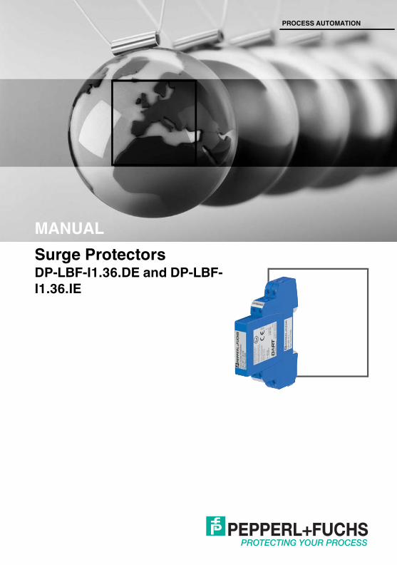
Surge ProtectorsDP-LBF-I1.36.DE and DP-LBF-I1.36.IE
PROCESS AUTOMATION
MANUAL

With regard to the supply of products, the current issue of the following document is applicable: The General Terms of Delivery for Products and Services of the Electrical Industry, published by the
Central Association of the Electrical Industry (Zentralverband Elektrotechnik und Elektroindustrie (ZVEI) e.V.) in its most recent version as well as the supplementary clause: "Expanded reservation
of proprietorship"
Surge Protectors
Surge ProtectorsContents
2012
-11
3
1 Safety................................................................................... 41.1 Validity ..........................................................................................................41.2 Symbols used ...............................................................................................41.3 System Operator and Personnel ...................................................................41.4 Pertinent Laws, Standards, Directives, and further Documentation ...............51.5 Delivery, Transport and Storage ....................................................................51.6 Marking.........................................................................................................51.7 Intended Use ................................................................................................61.8 Mounting and Installation in Hazardous Areas ..............................................61.9 Housing ........................................................................................................71.10 Repair and Maintenance...............................................................................71.11 Disposal ........................................................................................................7
2 Product Specifications....................................................... 82.1 Overview and Application .............................................................................82.2 Component Overview ...................................................................................82.3 Technical Data ............................................................................................122.4 Dimensions.................................................................................................14
3 Installation and Commissioning ..................................... 153.1 Mounting.....................................................................................................153.2 Connection .................................................................................................163.3 Shielding and Grounding the Cable Shield .................................................17
4 Dismounting the Surge Protector ................................... 18
Surge Protectors
Surge ProtectorsSafety
Surge Protectors
2012
-11
1 Safety1.1 Validity
Specific processes and instructions in this document require special precautions to guarantee the safety of the operating personnel.
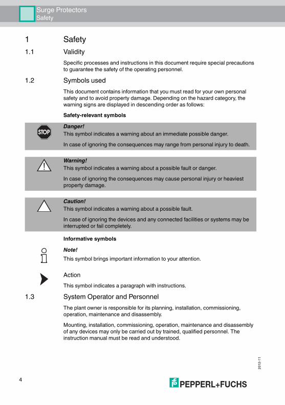
1.2 Symbols usedThis document contains information that you must read for your own personal safety and to avoid property damage. Depending on the hazard category, the warning signs are displayed in descending order as follows:Safety-relevant symbols
Informative symbols
ActionThis symbol indicates a paragraph with instructions.
1.3 System Operator and PersonnelThe plant owner is responsible for its planning, installation, commissioning, operation, maintenance and disassembly.Mounting, installation, commissioning, operation, maintenance and disassembly of any devices may only be carried out by trained, qualified personnel. The instruction manual must be read and understood.
Danger!This symbol indicates a warning about an immediate possible danger.In case of ignoring the consequences may range from personal injury to death.
Warning!This symbol indicates a warning about a possible fault or danger.In case of ignoring the consequences may cause personal injury or heaviest property damage.
Caution!This symbol indicates a warning about a possible fault.In case of ignoring the devices and any connected facilities or systems may be interrupted or fail completely.
Note!This symbol brings important information to your attention.
4
Surge ProtectorsSafety
2012
-11
1.4 Pertinent Laws, Standards, Directives, and further DocumentationLaws, standards, or directives applicable to the intended use must be observed. In relation to hazardous areas, Directive 1999/92/EC must be observed.The corresponding data sheets, declarations of conformity, EC Type-examination certificates, certificates and Control Drawings if applicable (see data sheet) are an integral part of this document. You can find this information under www.pepperl-fuchs.com.Due to constant revisions, documentation is subject to permanent change. Please refer only to the most up-to-date version, which can be found under www.pepperl-fuchs.com.
1.5 Delivery, Transport and StorageCheck the packaging and contents for damage. Check if you have received every item and if the items received are the ones you ordered.Keep the original packaging. Always store and transport the device in the original packaging.Always store the device in a clean and dry environment. The permitted storage temperature (see data sheet) must be considered.
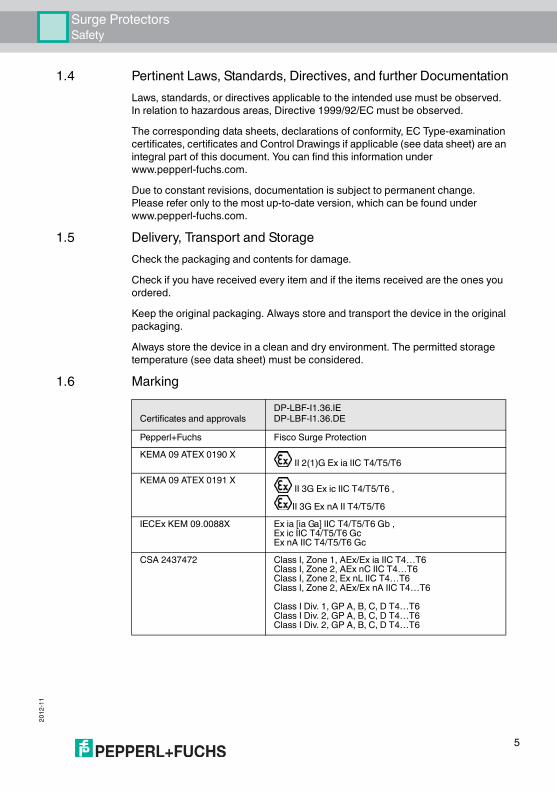
1.6 Marking
Certificates and approvalsDP-LBF-I1.36.IEDP-LBF-I1.36.DE
Pepperl+Fuchs Fisco Surge ProtectionKEMA 09 ATEX 0190 X
II 2(1)G Ex ia IIC T4/T5/T6KEMA 09 ATEX 0191 X
II 3G Ex ic IIC T4/T5/T6 ,II 3G Ex nA II T4/T5/T6
IECEx KEM 09.0088X Ex ia [ia Ga] IIC T4/T5/T6 Gb ,Ex ic IIC T4/T5/T6 Gc Ex nA IIC T4/T5/T6 Gc
CSA 2437472 Class I, Zone 1, AEx/Ex ia IIC T4…T6Class I, Zone 2, AEx nC IIC T4…T6Class I, Zone 2, Ex nL IIC T4…T6Class I, Zone 2, AEx/Ex nA IIC T4…T6Class I Div. 1, GP A, B, C, D T4…T6Class I Div. 2, GP A, B, C, D T4…T6Class I Div. 2, GP A, B, C, D T4…T6
5
Surge ProtectorsSafety
2012
-11
1.7 Intended UseThe modular FieldConnex® Surge Protectors protect fieldbus equipment safely from damages caused by surge voltages or lightning strikes.The surge protectors are designed for use in the fieldbus communication system according to IEC 61158-2 as Foundation Fieldbus and PROFIBUS PA.Both versions DP-LBF-I1.36.DE and DP-LBF-I1.36.IE are suitable for mounting in Zone 1 or Zone 2. The associated apparatus circuit may be led into Zone 0 if the intrinsically safe fieldbus power circuit is certified accordingly. It can also be used in intrinsically safe fieldbus installations in accordance with the FISCO and Entity model, as well as in DART fieldbus systems by Pepperl+Fuchs. The surge protectors are mountable on a DIN mounting rail only. For use in hazardous areas Class I Div 1, Class I Zone 1, Class I Div 2, and Class 1 Zone 2 refer to installation drawing 116-0361.
1.8 Mounting and Installation in Hazardous AreasThe surge protectors may be used in intrinsically safe fieldbus systems according to the FISCO or Entity concept. The surge protector itself may be installed in hazardous area Zone 2 and Zone 1, Gas Groups IIC, IIB, IIA.Connection between a surge protector and earth must have a minimum core cross section of 4 mm2. If the fieldbus cable of a surge protector leads into Zone 0, the cable length must be limited to 1 meter. If led into Zone 0, the fieldbus cable must be protected against interferences caused by lightning. The shield of the fieldbus cable must not lead into Zone 0 if it is not safely earthed like an equipotential bonding conductor according to IEC 60079-14.All separation distances between two adjacent intrinsically safe circuits need to be observed in accordance with IEC/EN 60079-14.All separation distances between two adjacent intrinsically safe circuits need to be observed in accordance with IEC/EN 60079-14.The lines connected to the surge protector must be shielded or covered by a metal coating or be passed within a metal pipe.The dielectric strength of at least 500 V of the intrinsically safe circuit of the device is limited only by the overvoltage protection. The terminals 5, 6, 7, and 8 are considered to be connected to earth.The device has to be installed into a metal housing, or into a housing that is certified for this kind of use.When the device is used in a fieldbus system according to FISCO, the power supply must have infallible galvanic isolation and may not be connected to earth. Alternatively the power supply must be infallibly connected to the potential equalizing system within the hazardous area.For use in the types of protection Ex nA IIC T4 ... T6 and Ex nA IIC T4 ... T6 Gc the device must be installed in an enclosure see chapter 1.9.
6
Surge ProtectorsSafety
2012
-11
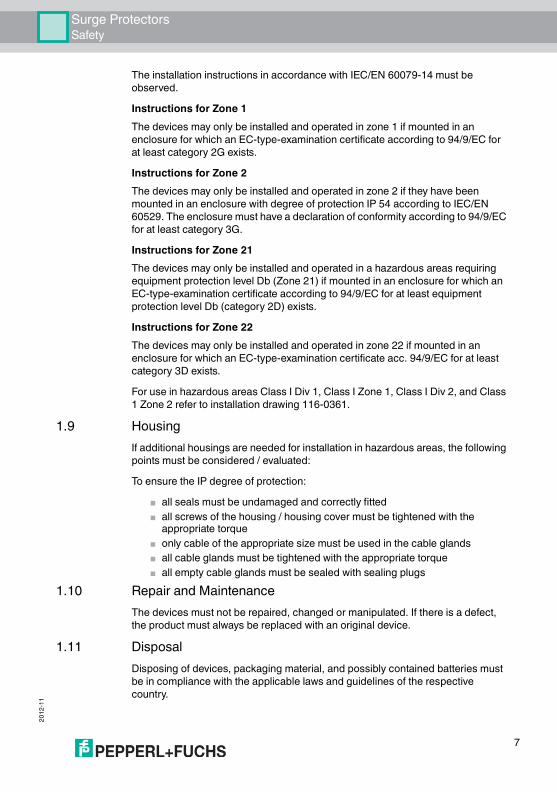
The installation instructions in accordance with IEC/EN 60079-14 must be observed.Instructions for Zone 1The devices may only be installed and operated in zone 1 if mounted in an enclosure for which an EC-type-examination certificate according to 94/9/EC for at least category 2G exists.Instructions for Zone 2The devices may only be installed and operated in zone 2 if they have been mounted in an enclosure with degree of protection IP 54 according to IEC/EN 60529. The enclosure must have a declaration of conformity according to 94/9/EC for at least category 3G.Instructions for Zone 21The devices may only be installed and operated in a hazardous areas requiring equipment protection level Db (Zone 21) if mounted in an enclosure for which an EC-type-examination certificate according to 94/9/EC for at least equipment protection level Db (category 2D) exists.Instructions for Zone 22The devices may only be installed and operated in zone 22 if mounted in an enclosure for which an EC-type-examination certificate acc. 94/9/EC for at least category 3D exists.For use in hazardous areas Class I Div 1, Class I Zone 1, Class I Div 2, and Class 1 Zone 2 refer to installation drawing 116-0361.
1.9 HousingIf additional housings are needed for installation in hazardous areas, the following points must be considered / evaluated:To ensure the IP degree of protection:
■ all seals must be undamaged and correctly fitted■ all screws of the housing / housing cover must be tightened with the
appropriate torque■ only cable of the appropriate size must be used in the cable glands■ all cable glands must be tightened with the appropriate torque■ all empty cable glands must be sealed with sealing plugs
1.10 Repair and MaintenanceThe devices must not be repaired, changed or manipulated. If there is a defect, the product must always be replaced with an original device.
1.11 DisposalDisposing of devices, packaging material, and possibly contained batteries must be in compliance with the applicable laws and guidelines of the respective country.
7
Surge ProtectorsProduct Specifications
Surge Protectors
2012
-11
2 Product Specifications2.1 Overview and Application
The FieldConnex® Surge Protector protects fieldbus components and control units from damage caused by voltage surges and lightning strikes. Voltages between the fieldbus leads 'plus' and 'minus', and between either lead and ground are limited safely. The surge protector is designed for use in fieldbus communication topologies according to IEC 61158-2. It conforms to IEC 60079: FISCO and Entity concepts and is DART-enabled.The surge protector allows the coordinated use in an EMC-oriented Lightning Protection Zones Concept in accordance with IEC 61312-1. The protective effect is adapted to the EMC interference immunity (conducted high energy interference impulses) for fieldbus measuring, control, and equipment.
The FieldConnex® Surge Protector consists of a base part and a protection module. It can be configured according to the maintenance concept of the plant with choices of modules as shown in the following table:
Base parts and protection modules are separately available. The two grounding methods support all cable shield grounding concepts used in fieldbus applications today.
2.2 Component OverviewThe modular surge protector DP-LBF-I1* always consists of two parts:
■ Base part■ Protection module
The two protection modules may be combined with two different base parts with or without communication interruption while the protection module is removed.
Type Code Module Type Comment ApplicationOn removal of protection module …
DB-LBF-I1 Base … communication continues
Replacement of the protection module during operation
DB-LBF-I1.I Base … communication interrupts
Replacement of the protection module only offline
Connection of shield to earth ...
DP-LBF-I1.36.DE Protection ... direct For double-sided grounding
DP-LBF-I1.36.IE Protection ... via gas discharge tube
For single-point grounding
Table 2.1 FieldConnex® Surge Protector Components and Attributes
8
Surge ProtectorsProduct Specifications
2012
-11
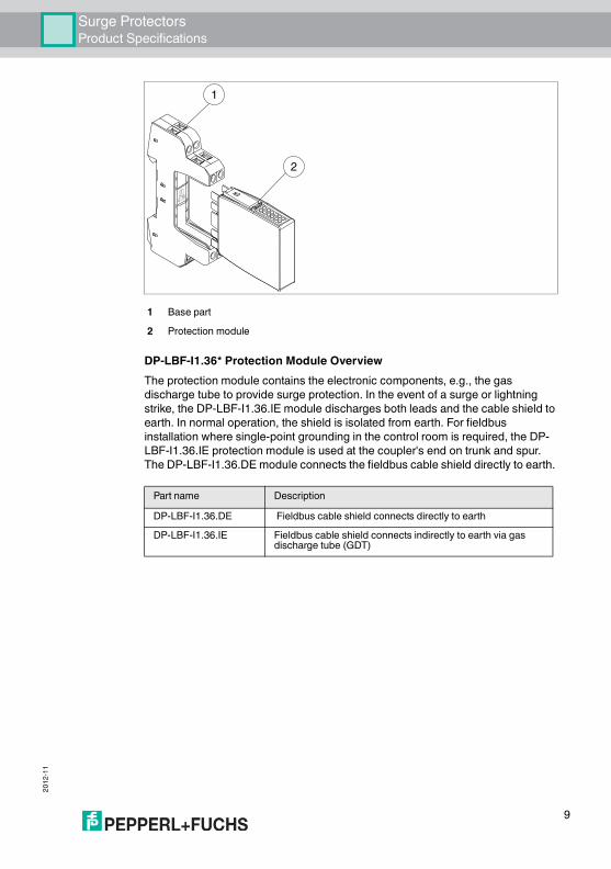
DP-LBF-I1.36* Protection Module OverviewThe protection module contains the electronic components, e.g., the gas discharge tube to provide surge protection. In the event of a surge or lightning strike, the DP-LBF-I1.36.IE module discharges both leads and the cable shield to earth. In normal operation, the shield is isolated from earth. For fieldbus installation where single-point grounding in the control room is required, the DP-LBF-I1.36.IE protection module is used at the coupler's end on trunk and spur. The DP-LBF-I1.36.DE module connects the fieldbus cable shield directly to earth.
1 Base part2 Protection module
Part name DescriptionDP-LBF-I1.36.DE Fieldbus cable shield connects directly to earthDP-LBF-I1.36.IE Fieldbus cable shield connects indirectly to earth via gas
discharge tube (GDT)
1
2
9
Surge ProtectorsProduct Specifications
2012
-11
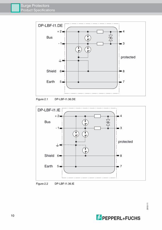
Figure 2.1 DP-LBF-I1.36.DE
Figure 2.2 DP-LBF-I1.36.IE
protected
+ 2
- 1
4
3
6 8
5 7
Bus
Shield
Earth
DP-LBF-I1.DE
protected
+ 2
- 1
4
3
6 8
5 7
Bus
Shield
Earth
DP-LBF-I1.IE
10

Surge ProtectorsProduct Specifications
2012
-11
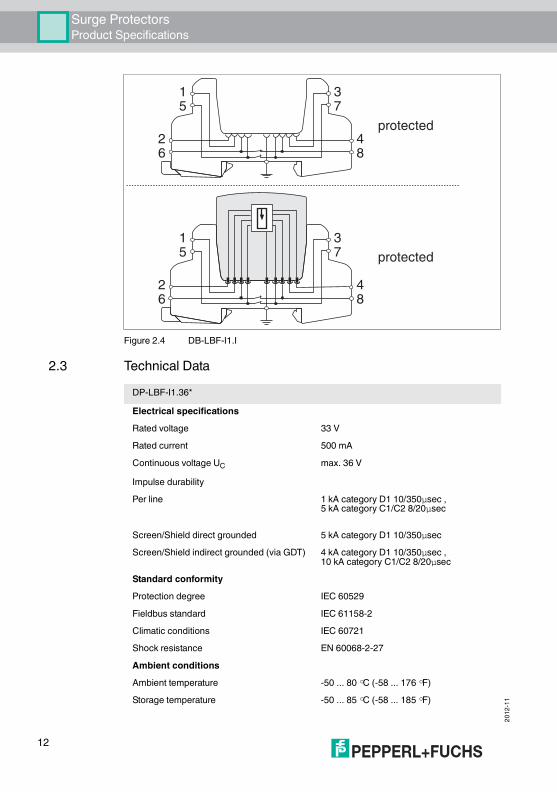
DB-LBF-I1* Base Part OverviewThe DB-LBF-I1* base parts serve as mechanical support for the DP-LBF-I1.36* protection modules. Electronic modules lead surge currents through the base parts to the DIN rail. Provided the DIN rail is installed isolated from earth, a dedicated terminal allows to connect the earth via an external wire to the base module. The DB-LBF-I1 version keeps the communication with the signal lines up while the electronic module is removed from the base module. The DB-LBF-I1.I version interrupts communication with the signal lines when the electronic module is removed.
Figure 2.3 DB-LBF-I1
Part name DescriptionDB-LBF.I1 Base part without signal interruption during removal of the protection
module.DB-LBF.I1.I Base part with signal interruption during removal of the protection
module.
protected
protected26
48
15
37
26
48
15
37
11
Surge ProtectorsProduct Specifications
2012
-11
Figure 2.4 DB-LBF-I1.I
2.3 Technical Data
protected
protected26
48
15
37
26
48
15
37
DP-LBF-I1.36*Electrical specificationsRated voltage 33 VRated current 500 mAContinuous voltage UC max. 36 VImpulse durabilityPer line 1 kA category D1 10/350µsec ,
5 kA category C1/C2 8/20µsec
Screen/Shield direct grounded 5 kA category D1 10/350µsecScreen/Shield indirect grounded (via GDT) 4 kA category D1 10/350µsec ,
10 kA category C1/C2 8/20µsecStandard conformityProtection degree IEC 60529Fieldbus standard IEC 61158-2Climatic conditions IEC 60721Shock resistance EN 60068-2-27Ambient conditionsAmbient temperature -50 ... 80 °C (-58 ... 176 °F)Storage temperature -50 ... 85 °C (-58 ... 185 °F)
12
Surge ProtectorsProduct Specifications
2012
-11
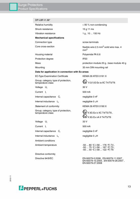
Relative humidity 95 % non-condensingShock resistance 15 g 11 msVibration resistance 1 g , 10 ... 150 HzMechanical specificationsConnection type screw terminalsCore cross-section flexible wire 2.5 mm2 solid wire max. 4
mm2
Housing material Polyamide PA 6.6Protection degree IP20Mass protection module 20 g , base module 40 gMounting 35 mm DIN mounting railData for application in connection with Ex-areasEC-Type Examination Certificate KEMA 09 ATEX 0191 XGroup, category, type of protection, temperature class II 2(1)G Ex ia IIC T4/T5/T6Voltage Ui 30 VCurrent Ii 500 mAInternal capacitance Ci negligible 0 nFInternal inductance Li negligible 0 µHStatement of conformity KEMA 09 ATEX 0190 XGroup, category, type of protection, temperature class II 3G Ex ic IIC T4/T5/T6 ,
II 3G Ex nA II T4/T5/T6Voltage Ui 33 VCurrent Ii 500 mAInternal capacitance Ci negligible 0 nFInternal inductance Li negligible 0 µHAmbient conditionsAmbient temperature -50 ... 80 °C (-58 ... 176 °F) T4 ,
-50 ... 75 °C (-58 ... 167 °F) T5 ,-50 ... 50 °C (-58 ... 122 °F) T6
Directive conformityDirective 94/9/EC EN 60079-0:2006 , EN 60079-11:2007 ,
EN 60079-15:2005 , EN 60079-26:2007 , EN 60079-27:2008
DP-LBF-I1.36*
13
Surge ProtectorsProduct Specifications
2012
-11
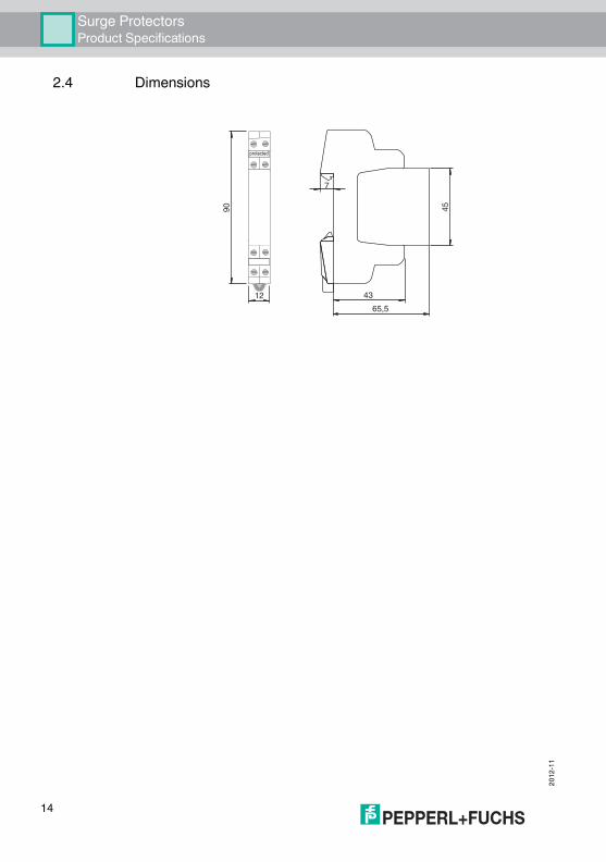
2.4 Dimensions
43
7
45
12
90
65,5
14

Surge ProtectorsInstallation and Commissioning
2012
-11
Surge Protectors
3 Installation and Commissioning3.1 Mounting
Mounting the Base Part on a DIN RailThe surge protectors are to be mounted on a 35 mm Din rail compliant with DIN EN 60715.1. Place the base part on the DIN rail2. Gently press the base part to the DIN rail until it is locked in place
Warning!Electrostatic chargeElectrostatic charged surfaces may cause an ignition spark.Clean surfaces with a damp cloth to prevent electrostatic charge.
min. 4 mm2 / min. AWG
15
Surge ProtectorsInstallation and Commissioning
2012
-11
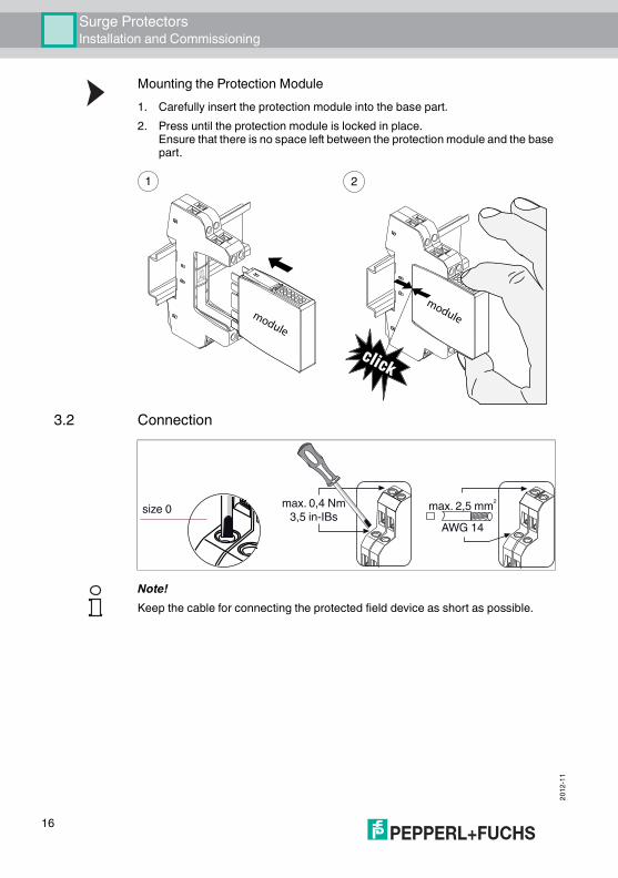
Mounting the Protection Module1. Carefully insert the protection module into the base part.2. Press until the protection module is locked in place.
Ensure that there is no space left between the protection module and the base part.
3.2 Connection
module
1 2
click
module
max. 0,4 Nm3,5 in-IBssize 0 max. 2,5 mm2
AWG 14
Note!Keep the cable for connecting the protected field device as short as possible.
16
Surge ProtectorsInstallation and Commissioning
2012
-11
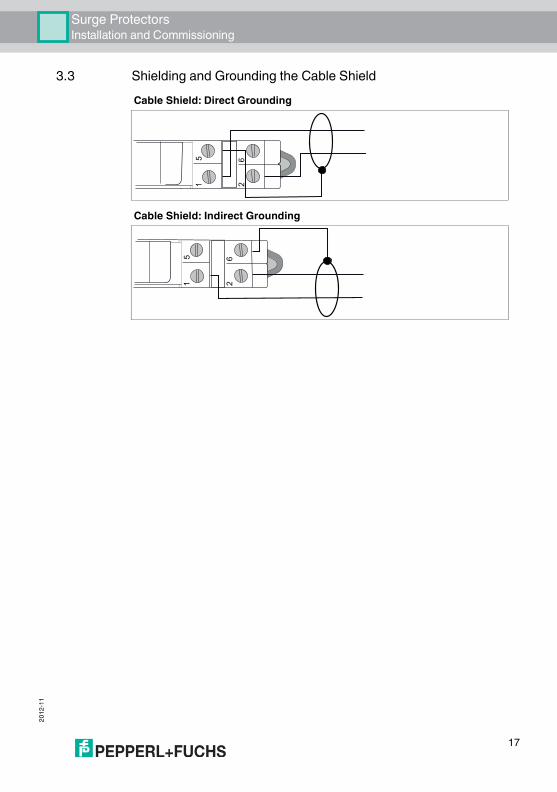
3.3 Shielding and Grounding the Cable ShieldCable Shield: Direct Grounding
Cable Shield: Indirect Grounding1 2
5 6
1 2
5 6
17
2012
-11
18
Surge ProtectorsDismounting the Surge Protector
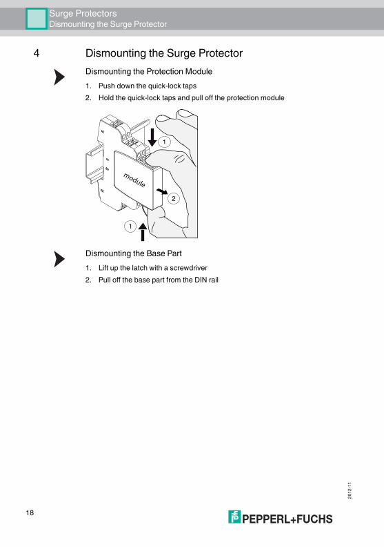
4 Dismounting the Surge ProtectorDismounting the Protection Module1. Push down the quick-lock taps2. Hold the quick-lock taps and pull off the protection module
Dismounting the Base Part1. Lift up the latch with a screwdriver 2. Pull off the base part from the DIN rail
module
1
1
2
Surge Protectors

Subject to modificationsCopyright PEPPERL+FUCHS • Printed in Germany
www.pepperl-fuchs.com
PROCESS AUTOMATION – PROTECTING YOUR PROCESS
Worldwide HeadquartersPepperl+Fuchs GmbH68307 Mannheim · GermanyTel. +49 621 776-0E-mail: [email protected]
For the Pepperl+Fuchs representative closest to you check www.pepperl-fuchs.com/contact
TDOCT-2096_ENG11/2012