Embed Size (px)
Citation preview
8/20/2019 MANUAL SERVICIO EKG BURDICK EK10.pdf
http://slidepdf.com/reader/full/manual-servicio-ekg-burdick-ek10pdf 1/39
/-\
n
$crvtGc
nn
anu
al

8/20/2019 MANUAL SERVICIO EKG BURDICK EK10.pdf
http://slidepdf.com/reader/full/manual-servicio-ekg-burdick-ek10pdf 2/39
Service
Manual
t\
{/
,l
CONTENTS
GENERAL
INFORMATION
PAC
Basic
System
Description
..............
Block
Diagram..............
Soecifications...............
SERVICE
Safety
and
Service
Cautions
.......................5
Tools and Test
Equipment.......,.....
............
5
Printhead
Disable.......
............
5
Automatic
Shutdown
Disable
..............,.....
5
Setup
for
24OV 50/60H2
.....,.............
...,.,.. .5
SAFETY
AND PERFORMANCE
CHECKS
Chassis
Leakage.....
.................6
Patient
Leakage
..................,....6
Printhead
Dot
Test......
..............6
Printhead Protection
Test............
............. ..6
1
1.1
1.2
LJ
2
2.1
2.2
¿.J
2.4
2.4
3
3.1
3.2
3.3
J.+
-
3
)
I
8/20/2019 MANUAL SERVICIO EKG BURDICK EK10.pdf
http://slidepdf.com/reader/full/manual-servicio-ekg-burdick-ek10pdf 3/39
EK
1
0
Et
e c
trocardiog
rap,
h
THEORY
OF OPERATION
I
8.1
8,2
QA
ó.b
8.7
SCHEMATICS
AND
COMPONENT
DIAGRAM
Power
Supply
Circuit
Schematic..
.............28
lnput
Circuit
Schematic
..........28
I
nput
Circuit Schematic
(continued)
.......................28
Logic Circuit Schematic
.........28
Logic Circuit Schematic
(continued)
.........28
EK10
PCB
Component
Diagram
(prior
to
Rev.
D).......
.....,..............28
EK10
PCB
Component
Diagram
(Rev,
D
and
after)...
.....................28

8/20/2019 MANUAL SERVICIO EKG BURDICK EK10.pdf
http://slidepdf.com/reader/full/manual-servicio-ekg-burdick-ek10pdf 4/39
Seruice
Manual
I
h
I
t
,1
I
I
a
I
Fl
1
GENERAL
INFORMATION
1.1 BASIC
SYSTEM
DESCRIPTION
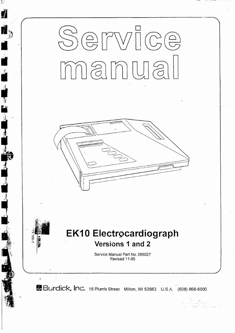
The
EK10
is
a
single channel electrocardio-
graph
which
uses a thermal
array
wr¡t¡ng
sys-
tem to
standard
electrocardiograms.
An
optional
nicad
battery allows the
EK10
to
oper-
ate
independently of the
AC
power
line for
about
an
hour
(long
enough to acquire approxi-
mately 50
ECGs)
before recharging
is neces-
'sary.
A
single
pr¡nted
circuit board
assembly,
the
EK10
PCB,
contains the
main circuitry
for
the
system.
The 12.5V
nicad
battery
provides
power
when
an
AC
power
source
is not con-
nected, This battery is recharged whenever the
EK'10
is
plugged
into
an
AC
line
and the power
switch
is
ON.
A logic
switch allows
the battery
to
charge continuously, even
when the
rest
of
the circuitry
is inactive.
Overcharge
protection
is
built-in.
ECG data signals
are
acquired,
amplified,
fil-
tered, and digitized before
being
processed
further
by the
system. A microprocessor han-
dles control functions. Operator
prompts
and
menus
appear
on a 2-line
by
2O-character
liq-
uid
crystaldisplay.
User
inputs
are
provided
by
means
of a
membrane
switch
keypad.
ECG
recordings
are
printed
by
the
writer
assembly,
whích consísts of a
48mm
thermal array
print-
head
and a
DC motor.

8/20/2019 MANUAL SERVICIO EKG BURDICK EK10.pdf
http://slidepdf.com/reader/full/manual-servicio-ekg-burdick-ek10pdf 5/39
EK
1
0
El
e ctrocardi
og
rap
h
1.3
SPECIFICATIONS
Dimensions:
Weight:
Power Requirements:
Mains voltage
fuses:
Battery
fuse:
Operating
tem
perature:
Storage
temperature:
Relative
humidity:
Frequency
response:
Input impedance:
Electrode offset
tolerance:
A/D
conversion:
Signal output
(version
2
only):
11" x
13"x
$3/16"
9lbs.
including
optional battery
110-120
I
220-240VAC
50/60H2
standard, 30VA
2.SVdc
nickel-cadmium
battery
(optional)
110-120V 2 x 0.3A slow blow,
3AG
220-240V,2
x
160mA
time
lag,
type
T
110-120V 24
slow
blow
3AG
220-240V,24 time
lag,
type
T
10"C
to
40'C
-34'C
to
70"C
15%
to
90%
non-condensing
meets
or exceeds AAMI standard (unfiltered)
.04H2 to
30H2,
-3dB (filtered)
greater
than
50M
ohm
*300mV
B
bits
1V
out
per
1mV
input,
r10%
gain
connector,
9-oin
D-subminiature

8/20/2019 MANUAL SERVICIO EKG BURDICK EK10.pdf
http://slidepdf.com/reader/full/manual-servicio-ekg-burdick-ek10pdf 6/39
Service
Manual
t
t
p
t
t
i
I
;-
I
t
t
h
0
2 SERVICE
2.1
SAFETY AND
SERVICE
CAUTIONS
CAUTION
-
Power
line
voltage
is
present
on
the
EKl0
PCB.
Main voltage
can be
encountered
at
the fuse,
power
switch, and
power
transformer.
Always
ensure that
the
unit
¡s
unplugged
whenever
you
are disas-
sembling
it.
The
EK|0
uses
CMOS
integrated
circuits
and caution
must
be
taken
dur¡ng
mainte-
nance
procedures
to
prevent
damage
which
can be
caused by static
electr¡city.
An
anti-static
work
surface
is
recommend-
ed.
Use
only Burdick-approved
thermal
ECG
recording paper.
Wax-coated or
blush-coat-
ed
paper
will
damage
the
printhead.
2.2
TOOLS AND
TEST
EQUIPMENT
The
EK.l0 requires only
standard
electronics
tools
for
maintenance
to
the board
level.
The
following
is
a
list
of suggested test equipment.
Note:
the
printhead
can
be
re-enabled
onl'¡
by
turning the
unit
OFF
and
then
ON
again.
3.
Return
to
the
main menu by selecting
RTNI.
2.4
AUTOMATIC
SHUT
DOWN DISABLE
The
EK10
automatically shuts down
(returns
to
standby)
after 15
minutes if
no
keys
are
pressed.
For
convenience during
repair
ses-
sions, this
feature
can
be
disabled as
follows:
1.
From
the
main menu,
press
front
panel
ke-vs
V4
and
V6
simultaneouslv
to enter the Test
&
Setup
Menu.
2.
Press
the
V4 key
and
the
EK.l0
v¡ill
display
a
message indicating
that the
15 minute
shut
down
is
disabled,
Note:
the automatic
shut
down can
be
re-
enabled only by turning the
unit
()FF
and
then
ON again.
3.
Return
to the
main menu
by
selecting
RTN.
2.5
SETUP FOR
24OV
5O/6OHZ
The
EK10
can
be
configured
easíly
for
opera-
tion at 240V
50/60H2 according
to the
following

8/20/2019 MANUAL SERVICIO EKG BURDICK EK10.pdf
http://slidepdf.com/reader/full/manual-servicio-ekg-burdick-ek10pdf 7/39
EK
1
0 Ele ctroc ardi
og
ra
p
h
3
SAFETY
AND
PERFOR.
MANCE CHECKS
NOTE
-
Leakage
tests
should be
conducted
with
a high
quality
meter
or
safety
analyzer
capable
of testing to
AAMI specifications.
lnappropriate meters can
produce
erro-
neous leakage
readings.
Leakage
tests
should be performed
at a
non-conductive
work
station.
WARNING
-
Use
caut¡on
when
conducting
/hese
fesfs.
The meter
must
be
suitably
insulated
and
capable
of
withstanding
the
power
line voltage.
3.1
CHASSIS LEAKAGE
1. Turn
the EK10
rear
panel power
switch ON.
2.
Connect
a
leakage meter
between the
rear
panel
chassis
ground
iack
and
power
line
ground.
Ensure that
leakage
current
is less
than
1@pA.
3.
Open
ground
line
and ensure
leakage
cur-
6.
With
reversed
polarity,
open ground
line
and
ensure
leakaoe
current
is less
than
2AuA.
3.3
PRINTHEAD
DOT
TEST
This
test can be used to determine
if
all the
indi-
vidual
printhead
dots
are
functioning
properly.
1.
From
the
main menu, press front panel
keys
V4
and
V6
simultaneously to enter
the
Test
& Setuo
Menu.
2.
3.
Press
the
Lead
I
key
to
initiate
test.
The writer
will
a
diagonal
line,
which
should
be
inspected
for
continuity,
Fading
at the top
or
bottom of
the
page
indicates
that the
printhead
is
mis-aligned.
Individua,
dots
or
groups
of
dots
which
do
not
indicate
a
problem
with
the
printhead
con-
trol circuitry
or the
printhead
itself.
Always
ensure that
the
pi'inthead
and
paper
path
are
kept
free
of
dirt or
other
foreign mater¡al.
For
additional
information,
refer
to
section
6
Maintenance.
Return
to
the
main menu
by selecting
RTN.

8/20/2019 MANUAL SERVICIO EKG BURDICK EK10.pdf
http://slidepdf.com/reader/full/manual-servicio-ekg-burdick-ek10pdf 8/39
Service Manual
l¿
IT
lr
F
T
lr
F
lr
4 PROBLEM
SOLVING
4.1
TROUBLESHOOTING
Past
experience
has
shown
that
a
large
per
centage
of
service
calls
are
due to
poor
ECG
technique and
broken
cables.
Before
disassem-
bling
the electrocardiograph,
ensure
that
tech-
nique
and
faulty
cables
are
eliminated
as
the
source
of
the
problem.
Refer
to
the Operator's
Manual for additional
information,
8/20/2019 MANUAL SERVICIO EKG BURDICK EK10.pdf
http://slidepdf.com/reader/full/manual-servicio-ekg-burdick-ek10pdf 9/39
EK
|
0
Ele ctrocard
i
og
rap
h
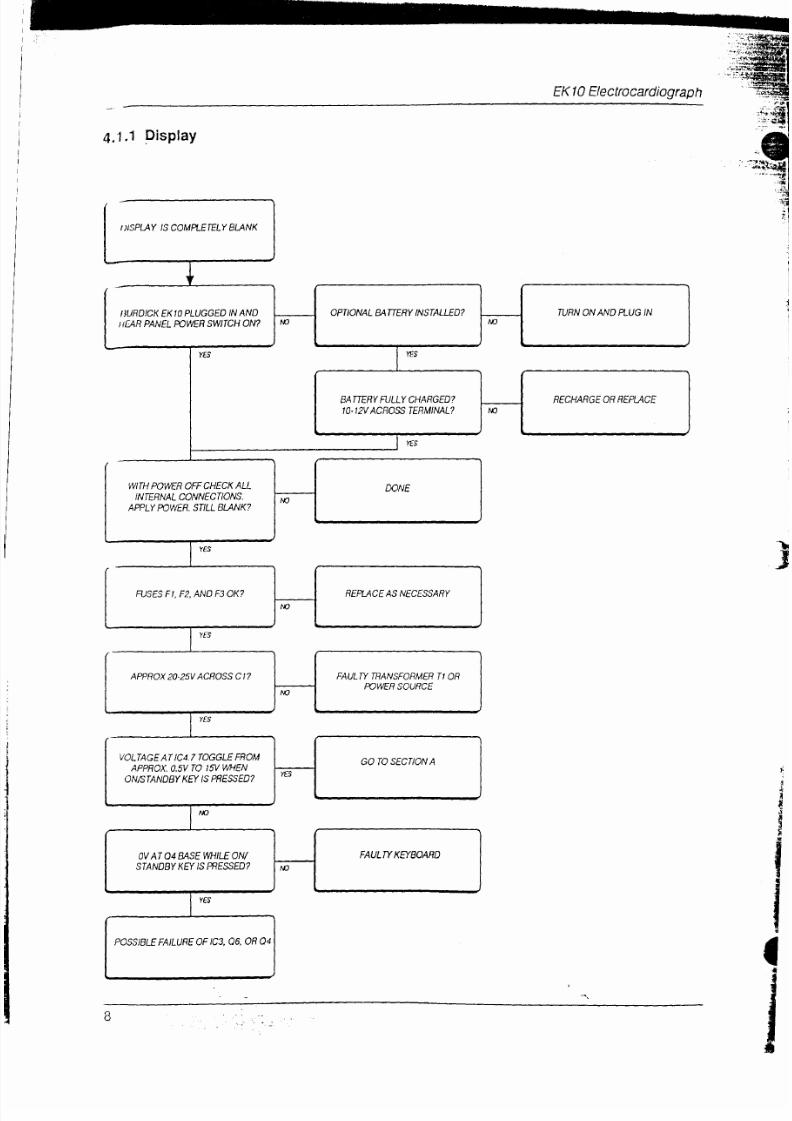
4.1.1
Display
I )I
SPLAY
IS
COMPLETELY
BLr''NK
I)UNDDK EK\O
PLUCGED
IN AND
IIFAR
PANEL
rcWEB
SWI|CH
ON?
WTH
POWER
OFF
CHECK
ALL
INTERNAL
CONNECTIONS.
APPLY
rcWER.
STILLBUNK?
O PT O NAL B,{TTERY
N S
TAUE
D? TURN
ON
AND PI-UG IN
EATTEEY FULLY CHARGED?
1 O.
I
2V
ACROSS TERMINAL?
RECHARGE
OR
REPUCE
8/20/2019 MANUAL SERVICIO EKG BURDICK EK10.pdf
http://slidepdf.com/reader/full/manual-servicio-ekg-burdick-ek10pdf 10/39
Service
Manual
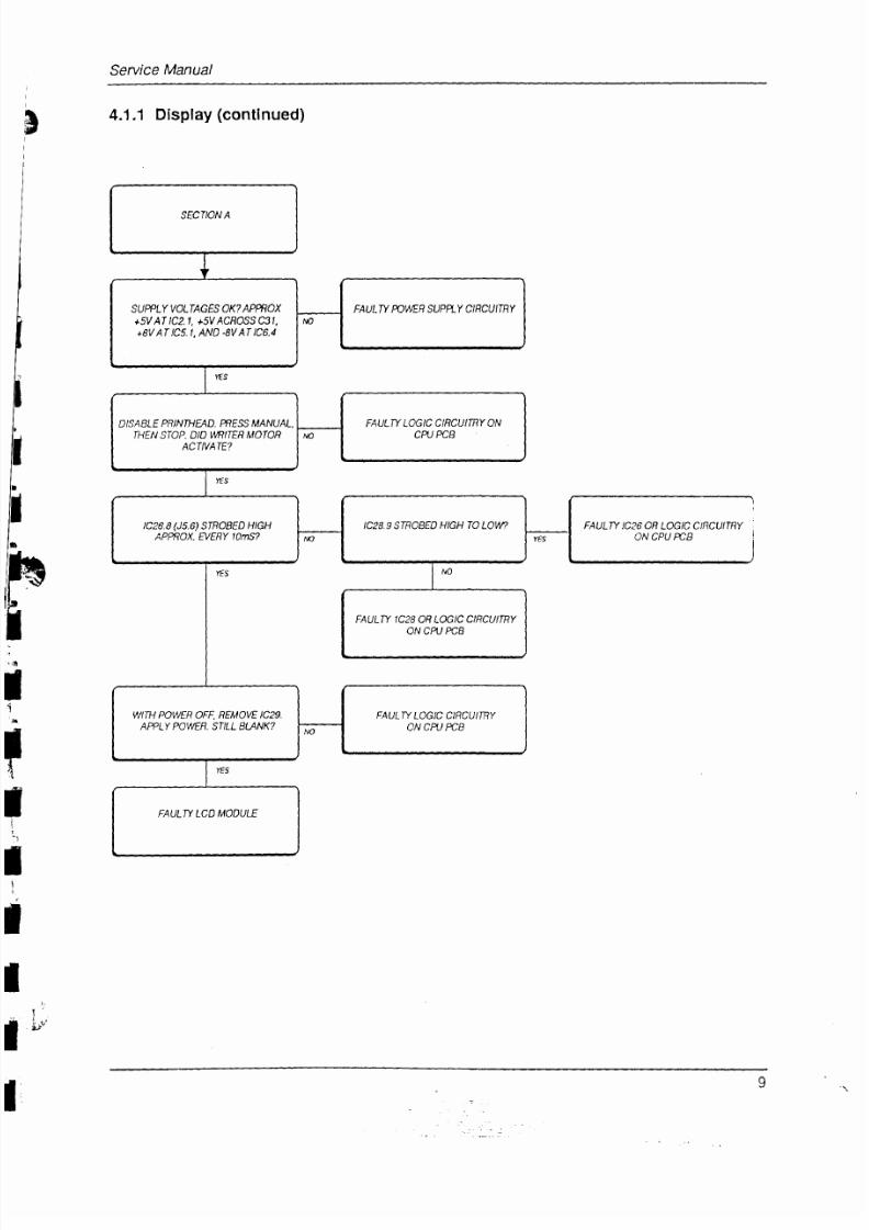
4.1.1
Display
(cont¡nued)
SUPPLY VOLTAGES OK?
APNOX
+5V
Af
1C2.1,
+5V
ACBOSS C3l,
+8V
AÍ
lCí.l.
AND-8V
Af
D6.4
FAULW
rcVEB
SUPftY CINCUÍRY
FAULTY LOGIC
CIRCUINY ON
CN
PCB
DISABLE
PRINTHFAD.
ffiESS
MANUAL,
ÍHEN
STAP.
DID WITER
MOTOR
ACTMATE?
tc26.e
us.6)
snoBED
HtGH
APnOX.
NERY
t)rns?
tc28.s snoBEo
H|GH To
LOW? FAULTY IC26
AB
LOGIC
CIRCUITRY
ON
CPU
rcB
8/20/2019 MANUAL SERVICIO EKG BURDICK EK10.pdf
http://slidepdf.com/reader/full/manual-servicio-ekg-burdick-ek10pdf 11/39
EK 1
0
El
e
ctrocardiog
rap
h
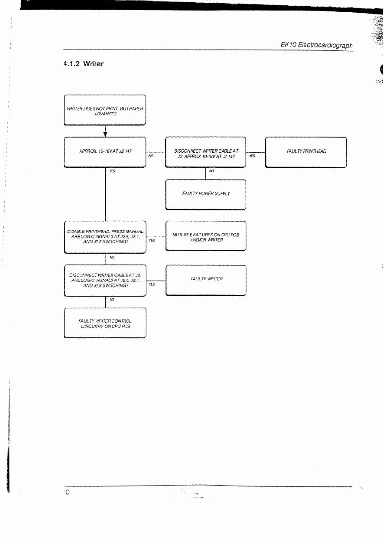
4.1.2
Writer
(
,;i:
WRITER
DOES
NOT PfrNT,
BUÍ PAPEB
ADVANCES
AP%OX.
t0.t6V
AT
J2.14? DISCONNECI WRITER
CABLE
Af
J2.
APffiOX
t0-t6v AT J2.14?
FAULIY
PRINTHEAO
FAULTY POWER
SUWLY
DISABLE
PRIN'|HEAD. PRESS
MANUAL
ARE
LAGIC
SIGNALS
AT J2.6,
J2.1,
AND J2.8 SWJTCHING?
MUTLIftE FAILURES
ON CPU
rcB
AND,OR WNITER

8/20/2019 MANUAL SERVICIO EKG BURDICK EK10.pdf
http://slidepdf.com/reader/full/manual-servicio-ekg-burdick-ek10pdf 12/39
EKl0 Electrocardiograph
ji*;
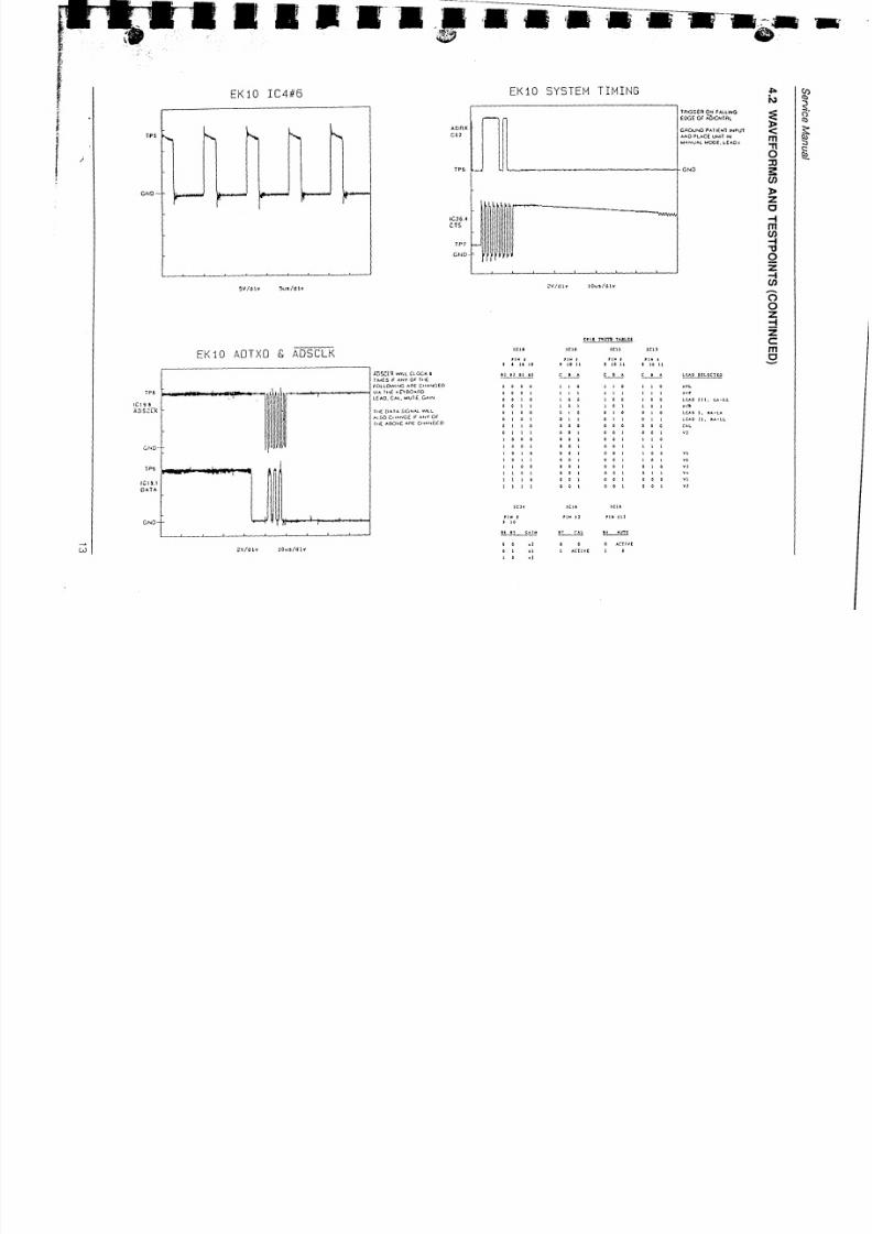
4.2
WAVEFORMS
AND
TESTPOINTS
q
lt
trJ
O
c)
:tr
F
CU
.q
O
ul
trJ
o
O
Z
N
O
\7,
LlJ
vO
FO
Ül
8/20/2019 MANUAL SERVICIO EKG BURDICK EK10.pdf
http://slidepdf.com/reader/full/manual-servicio-ekg-burdick-ek10pdf 13/39
ü3¡p
{
EKlO
SYSTEM
TIMING
EKlO
IC4#6
EKIO
ADTXO &
ADSCLK
¡r l a
nm
tuL ¡
.
rc¡o ¡c¡t
¡ct¡
tt¡
,
t¡N
I
tlr
I
r l0 t¡ t ¡0 lI t ¡0 r¡
c_L_^
c
I
^
Átgll
wrL
crocx a
livfS
rt
AñY
OF
lxÉ
fó tOwlf¡c
^A€
Cx^NCEO
vr^ TrrE
rEYBO^nD
L(
^o.
c^r.
sv¡ É, 6^r¡
frf
D^J^
S|oI^L
sLL
^{
SO C¡
¡^¡rof
rf
^trY
OF
Ilrt AOOVC
^t¡[
C,r^rcfO
2v/d\v
lou /ólv
rR6G€R
ON
F^TTWG
ÉoG€
oÉ
^b,cHlRL
6ROUñO
F^lr€fl
tñPurf
uO PUCE
UN¡l
¡{
u^ru^L @€.
t€aO
¡
La¡0
StLtc¡to
¡
t\,
€
m
ft
o
I
=
z
(]
{
m
@
{
lt
o
z
{
@
c)
o
z
{
z
c
m
g
c¡a
I
¡
¡t rt
n]
al
l r0
0oo¡¡0¡¡01r0^vt
001¡¡t¡l¡¡¡¡^ef
0t0¡00¡00tooLao¡¡¡.u- L
0
¡
| ¡
0 ¡
I
0
I I o
¡
A\a
I
O 0 0 r
0
0 I 0 o
I
0 tuo ¡, u-LA
I
O I 0 I
¡
O I t O
¡ ¡
lE¡O
l¡.
ú- t
¡ ¡
0 o 0 0 0
o o
o 0
0
c^L
I I I
0
o |
0
0
¡ o
0 ¡
v¡
0000 ¡oatt¡o
0ol oot0ol¡¡t
o
¡
o 0 0
¡
0 o I ¡ 0 0
vl
NO
TP9
tcr 9.r
O
ATA
¡00
l0¡
¡¡l
t ¡o
¡l tt
c^t¡
00¡
001
00¡0¡0
o0l 0¡¡
00¡000
001
001
11
c^L
t¡
x6
0
o
0
^cflvl
I
AC¡¡V¡ ¡
0
¡cll
rlN
t¡¡
0
0
¡l
I
rl
?Y /ólY
tolt/d11
I.
U)
(D
3.
o
(D
r
8/20/2019 MANUAL SERVICIO EKG BURDICK EK10.pdf
http://slidepdf.com/reader/full/manual-servicio-ekg-burdick-ek10pdf 14/39
EK
1
0
El
e
ctrocardiog
raph
J¿
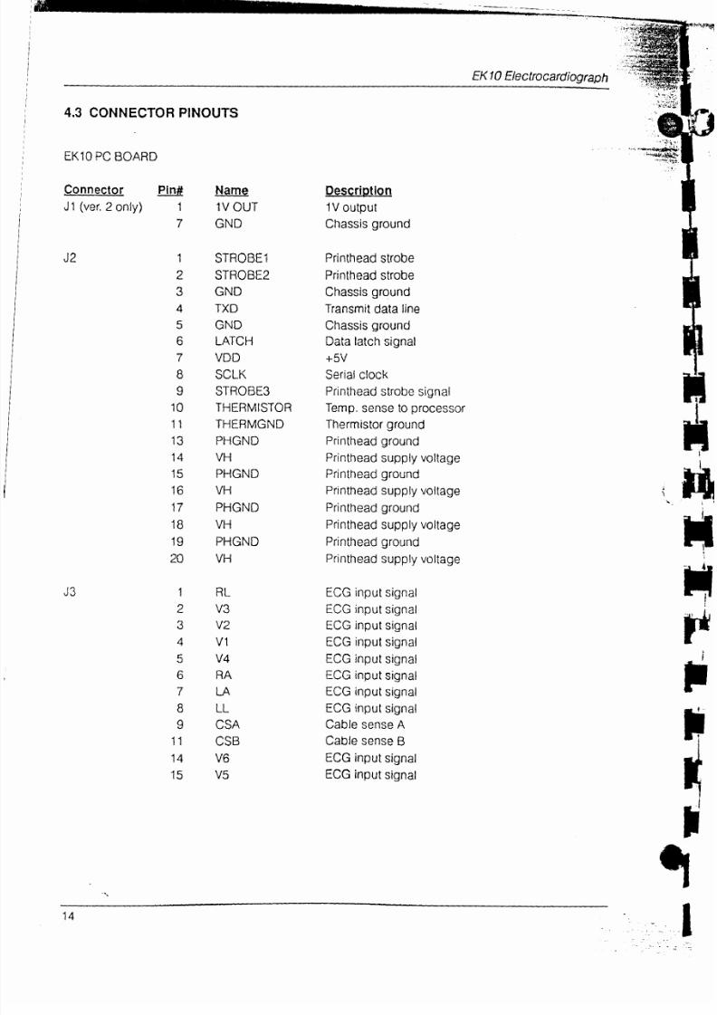
4.3
CONNECTOR
PINOUTS
EKIO PC
BOARD
Connector Pln#
J1
(ver.
2
only)
1
7
DescripJlon
'1V
output
Chassis
ground
Printhead strobe
Printhead
strobe
Chassis
ground
Transmit
data
line
Chassis
ground
Data latch
signal
+5V
Serial
clock
Printhead
strobe
signal
Temp.
sense
to
processor
Thermistor
ground
Printhead
ground
Pri nthead
supply
voltage
Pr¡nthead
ground
Printhead
supply voltage
1
I
¿
4
7
T
B
o
10
11
IJ
.A
t+
to
Name
1V
OUT
GND
STROBEl
STROBE2
GND
TXD
GND
LATCH
VDD
¡ULÑ
STROBE3
THERMISTOR
THERMGND
PHGND
VH
PHGND
VH
8/20/2019 MANUAL SERVICIO EKG BURDICK EK10.pdf
http://slidepdf.com/reader/full/manual-servicio-ekg-burdick-ek10pdf 15/39
Service
Manual
I
a
f
t
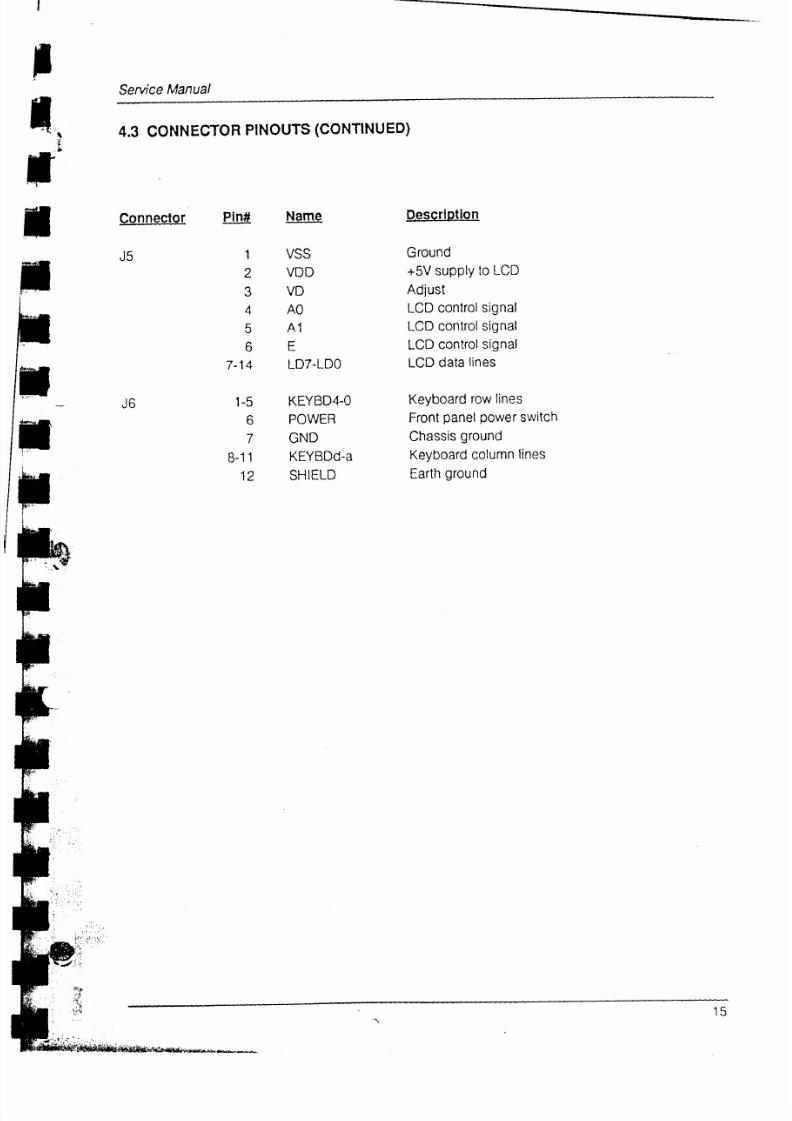
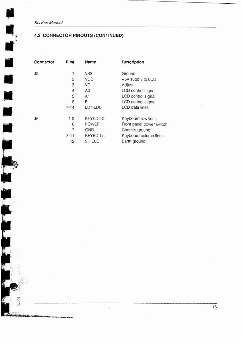
4.3 CONNECTOR
PINOUTS
(CONTINUED)
\
f
Connector
Name-
VDD
VD
AO
A1
E
LDT.LDO
KEYBD4-O
POWER
GND
KEYBDd.a
SHIELD
J6
Pln#
1
z
A
6
6
a aA
.tc
l-J
6
ó-ll
t¿
Descrlotion
Ground
+5V
supply
to
LCD
Adiust
LCD control
signal
LCD control
signal
LCD
control
sígnal
LCD
data
lines
Keyboard
row lines
Front
panel power switch
Chassis
ground
Keyboard
column
lines
Earth
ground
8/20/2019 MANUAL SERVICIO EKG BURDICK EK10.pdf
http://slidepdf.com/reader/full/manual-servicio-ekg-burdick-ek10pdf 16/39
EK
1
0 Ele ctroc
ardi
og rap
h
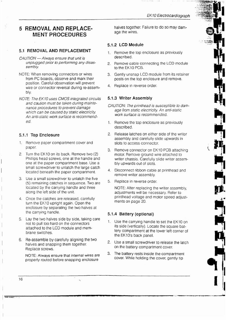
5
REMOVAL
AND
REPLACE.
MENT
PROCEDURES
5.1
BEMOVAL AND REPLACEMENT
CAUTION
-
Always
ensure that
unit
is
unplugged
prior
to
performing
any disas-
sembly.
NOTE:
When
removing connectors or
wires
from
PC
boards, observe and
mark their
position.
Careful
observation
will
prevent
wire
or connector
reversal durino re-assem-
bly.
NOTE:The EK10
uses
CMOS
integrated circuits
and
cautton
must
be
taken
during
mainte-
nance
procedures
to
prevent
damage
which
can
be caused by
stat¡c electricity.
An anti-static
work
surface
is
recommend-
ed.
5.1.1
Top Enclosure
1,
Remove
paper
compartment cover
and
uducr,
2.
Turn
the EKlO
on
its
back.
Remove
two
(2)
halves
together.
Failure
to
do
so
may
dam-
age
the
wires.
5.1.2
LCD
Module
1.
Remove the
top enclosure
as
previously
described.
2.
Remove cable
connecting
the
LCD module
to
the
EK10
PCB.
3.
Gently
unsnap
LCD
module
from
its retainer
posts
on the top enclosure and
remove.
4.
Replace
in reverse
order.
5.1.3
Writer Assembly
CAUTION:The
printhead
is
susceptible
to
dam-
age
from
static
electr¡city.
An
ant¡-stat¡c
work
surface
is
recommended.
1.
Remove
the
top
enclosure as
previously
described.
2.
Release
latches on
either side
of
the
writer
assembly and
carefully slide
upwards
in
slots
to
access
connector.
3.
Remove
connector on
EKlO
PCB
atlaching
motor.
Remove
ground
wire
attached to
hr
el
\Fh
8/20/2019 MANUAL SERVICIO EKG BURDICK EK10.pdf
http://slidepdf.com/reader/full/manual-servicio-ekg-burdick-ek10pdf 17/39
Service
Manual
4.3
CONNECTOR
PTNOUTS
(CONTTNUED)
Connector
Name
v55
VDD
VD
AO
A1
E
LD7-LDO
KEYBD4.O
POWER
GND
KEYBDd-a
SHIELD
J6
Pln#
1
¿
3
4
5
o
a 1t
,- l$
1-5
6
7
B-1
1
12
D.escription
Ground
+5V
supply
to
LCD
Adjust
LCD control
signal
LCD
control
signal
LCD control
signal
LCD
data
l¡nes
Keyboard row lines
Front
panel
power
switch
Chassis ground
Keyboard
column
lines
Earth
ground

8/20/2019 MANUAL SERVICIO EKG BURDICK EK10.pdf
http://slidepdf.com/reader/full/manual-servicio-ekg-burdick-ek10pdf 18/39
the unit
so
the
weight
of
the
battery causes
lhe
cover to
drop out
of
place.
Use
a
long-nose
pliers
to
disconnect
the
battery terminal connector
from
the
PC
board. CAUTION:
Pullon
the
connector,
not
the
wires themselves.
5.
Replace in reverse order.
NOTE:
Ensure
that
battery
terminalwires
are
properly routed in the compartment
cover.
The wires
are
damaged
easily
if
they
become
trapped
between
the cover
and
main
assembly,
5.1.5
EK10
PCB
1.
Remove
the
battery
as
previously
described.
2.
Remove
the top
enclosure
as
previously
described.
3.
Remove
the
writer
assembly
as
prevíously
described.
4.
Unplug
connector
on
EK10
PCB
attaching
LCD module.
Lift
the
EK10
PCB
up
and out of
bottom
enclosure.
Replace in
reverse
order.
NOTE:After
replacing
the
EK10 PCB,
adjustments will be necessary.
Refer to
printhead
voltage
and motor
speed
adjustments
on
page
20
5.1.6
Battery
Fuse
The
battery
fuse is
located
on
the
EK10 PCB.
Refer
to
the
previous
instructions for
EK10 PCB
removal.
lf replacement
is necessary,
use
only a
fuse
of
the
same type and
rating.
5.1.7 Power Llne
Fuses
The
oower
line
fuses are accessible from
the
bottom
of the
EK10.
lf
reolacement
is
neces-
sary, use
only
a fuse of the
same type and
rat-
ing.
1.
Ensure
that the
unit
is
unplugged.
2.
Turn
the
EK10
on
its
back
and
locate
the
fuse
access cover
at
the corner of
unit.
o.
7.

8/20/2019 MANUAL SERVICIO EKG BURDICK EK10.pdf
http://slidepdf.com/reader/full/manual-servicio-ekg-burdick-ek10pdf 19/39
EKl
0
Electroca
rdiograph
l'.
5,2 EXPLODED
VIEW
007514
|j-Lead
Patient Cable
007958
Thermal
ECG
PaPer
(150ft.)
C47262
Pwer
Cord
833007
Line Fuse
833098 Line Fuse
(odd
voltage)
8330'f 4
gattery
Fuse
862276
Paper
Spool
862330
Top
Enclosure
w/membrane
switch
862302
LCO Module
AssemblY
8625'f
2
Paper
ComPartment
Cover
862282
Thrust
Eearlng
862269
Platen
Roller
862332
Paper
Drive AssemblY
I
n
;
8/20/2019 MANUAL SERVICIO EKG BURDICK EK10.pdf
http://slidepdf.com/reader/full/manual-servicio-ekg-burdick-ek10pdf 20/39
Seruice
Manual
r
lr
ir
Ir
n
ffl
:):/
6
MAINTENANCE
6.1 PREVENTIVE
MAINTENANCE
The
purpose
of
preventive
maintenance
is
to
eliminate
future
problerns
as
much as
possible
and to
keep
the
equipment
in
good
operating
condition.
This ensures
safe
and satisfactory
ECG
recordings.
THE FOLLOWING
PREVENTIVE
MAINTE-
NANCE CHECKS
SHOULD
BE
CARRIED
OUT
AT
LEAST ONCE
A
YEAR:
.
Visual insoection
.
Cleaning
.
Check
power
cord
.
Check
patient
cable
.
Check
leakage currents
Simple
maintenance routines, normally
per-
formed
darly
or
weekly
by
the
user,
are
described
in the
Operating
lnstructions.
In
the
event
of a malfunction,
refer
the
repair
to
an
authorized
Burdick
Service
Representative.
6.1.1
Msual
Inspection
.
Soft,
lint-free
cloth
.
Polishing cloth
.
Distilled
water
.
Mild detergent
solution
.
Soft
brush
Disconnect
the
AC
power
cord
before
attempt-
ing
any
cleaning. Clean
the
housing
with
a
damo cloth.
Do
not
use
abrasive cleaners
or
polishes.
Wipe
dry
with
a soft,
clean cloth.
Also,
wipe the
paper
compartment.
CAUTION:Avoid putt¡ng any liquids such
as
alcohol
or
solvents
directly
onto
the unit.
Contamination
from
liquids
may
result
in
severe
electrical
damage.
6.1.3 Power
Cable
Check the
power
cord
and appliance
inlet for
any
visible
signs
of deterioration,
loose
connec-
tions, or burn
damage.
6.1.4 Patient
Cable
Check
the
patient
cable
and
input connector
for
any
visible
signs
of damage
or
loose
connec-
tions.
Disconnect the
patient
cable
from
the
unit
and inspect
it for short
circuits, broken
wires, or
8/20/2019 MANUAL SERVICIO EKG BURDICK EK10.pdf
http://slidepdf.com/reader/full/manual-servicio-ekg-burdick-ek10pdf 21/39
EK
1
0 El
e
ctrocardiog
raph
will
provide
approximately
one
hour of
continu-
ous
service
(about
50
ECG recordings
in
AUTO
mode).
Approximately
15
hours are
required to
fully
recharge
the
battery.
NOTE:
The
EK10
can be
operated under
AC
power
without affecting
the charge
time.
However, if
the
battery becomes
completely
discharged, the
unit
will
not operate
even
under
AC
power.
About once every
6
months, the
EK10 should
be
allowed to
run
on battery
power
until
the
low
battery
indicator
(LB)
is
displayed on
the
main
menu.
Then recharge the
unit.
This
ensures
that
the
battery
will
operate
at full
capac¡ty.
Under
normal
circumstances,
the
battery's
life
expectancy
is
3
-
5
years.
6.4
PRINTHEAD VOLTAGE
ADJUSTMENT
lf
a
message indicating
high
or
low
printhead
resistance
is
displayed
when
the
EK10
is first
powered
up,
the
printhead
voltage
needs
adjustment.
Since
individual
printheads
vary in
resistance,
this
adjustment also
is
necessary
',vhenever
the EKlO
PCB
or
printhead
has been
lf necessary,
adiust
R109
until the
dis-
played
value
matches the
value
indicated
on the printhead. A
hole in
the battery
com-
..
partment
is
provided
for
access
to
R109.
To
terminate
the
adjustment
procedure,
press
STOP.
Return to the
main
menu
by
selecting
RTN.
6.5 PAPER
SPEED
ADJUSTMENT
This adlustrnent
should
be
performed
after
repair
or
replacement
of
the
EK10
PCB
or
writer
assembly.
lt
allows the
paper
speed to
be
adiusted
for
both
25mmis
and
50mm/s.
From the
main menu,
press
front
panel
keys
V4
and
VO
simultaneouslv
to enter the
Test
&
Setup
Menu.
Select
SPD
to
display
the
Speed Adjust
Menu.
From
this
menu.
select
either
25mm/s or S0mmis.
The writer
will
a
contlnuous strip of
cal-
ibration lines
until the STOP
key
is
pressed.
At
25mm/s the
marks
should
be Smm apart,
with
25mm
between the
large
tic
marks. At
SOmmis they should be
1Omm
apart,
with
+-
1.
2.
4.

8/20/2019 MANUAL SERVICIO EKG BURDICK EK10.pdf
http://slidepdf.com/reader/full/manual-servicio-ekg-burdick-ek10pdf 22/39
Service
Manual
6.6
ADJUSTMENT
LOCATIONS
The
following
adjustments
can be
accessed
írom the battery compartrnent:
A
-
50mm/s speed
adiustment
(R122)
B
-
25mm/s speed
adjustment
(R121)
C
-
Printhead
voltage
adjustment
(F109)
Also. refer
to
sections
8.6
and
8.7 EK10 PCB
Component
Diagram
for
the
location
of these
comDonents.
i'"L
r
II
ie
l Fi,
.i-
lrl
t,
lü
ll'
.t
.
It'
1,,
lr
r
|r
lf
AB
@@
8/20/2019 MANUAL SERVICIO EKG BURDICK EK10.pdf
http://slidepdf.com/reader/full/manual-servicio-ekg-burdick-ek10pdf 23/39
EK
1
0
El
e
ctrocardiog
rap
h
7 THEORY
OF OPERATION
7.1 EKl
O
PCB
Allof
the circuitry
for
the EK10
Electrocardio-
graph
is
contained
on a single
printed
circuit
board, the
EK.l0
PCB.
For
the
purpose
of
dis-
cussion,
the
circuitry
on this
board
can
be
iden-
tified as
follows:
power
supply,
amplifier,
micro-
processor, keyboard interface, motor
control,
orinthead
control,
and
LCD
¡nterface.
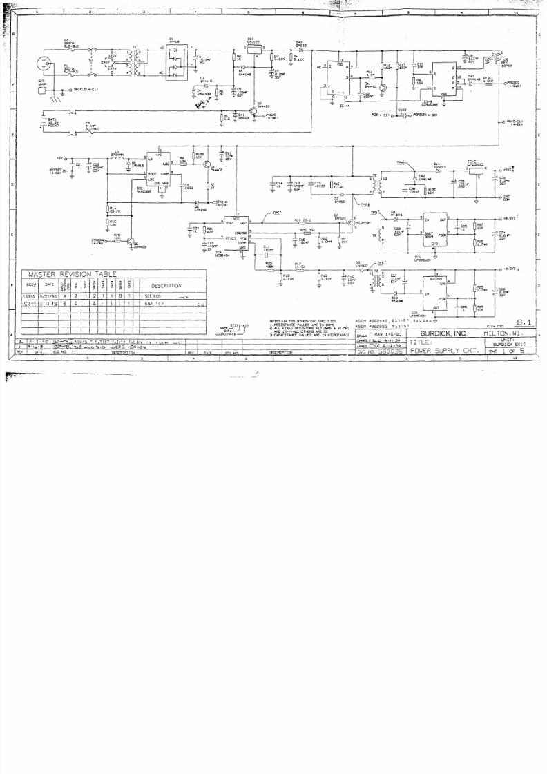
7.1.1
Power
Supply
The
EK.l0 can be
operated
at
line
voltages
of
120VAC
or
24OVAC. Jumpers
select
the
appro-
priate
setting.
The
line
voltage is applied
to
transformer
T1
through fuses
F1
andF2
and
the
rear
panel
power
switch,
S1.
An inductor
filters
electromagnetic
¡nterference
that
is radiated
from
the
power
line. The
transformer
secondary
provides
17VAC
to
rectifier
D1
,
The
rectifier
and
C1
produce
an unregulated
23V at
the
input
of
lC1,
a
voltage
regulator.
R2
provides
a current
path
for
D3
and
D4,
which together
form
a
13.6V reference.
CG
provides
ripple
filtering for
R10
debounce the
circuit.
Once the logic switch
is
on, power is
available
to
ail
the circuits at the
drain
of
Q6.
The logic
switch
can be turned off
by
pressing
the
front
panel power
ON/OFF switch
again, or by
the
PWRDWN signal
from
the
microprocessor.
In
either
case,
Q4
is turned off
again.
This
causes
the
output
of
lc3 at
pin
13
to
return
to
a
high
condition,
turn¡ng
off
the
logic
switch
Q6.
The
+5V power supply
is
generated 6y
lCZ,
which
has
an
internal
oscillator
that
produces
a
+SVDC
output through
DB,
L1
,
and
C22.
R14
and
R'f
5
provide
the
under
voltage
sensor
input.
When
the
output
falls
below
4.4V
Q3
turns
on
to
produce
the
strobe
inhibit
signal,
STRINH.
This
signal
prevents
strobe
pulses
from
enabling
the
printhead,
lf
a strobe
error
is
detected,
the
STRERR signal
turns
on
Q5
to
force the strobe
inhibit.
The
isolated
power
supplies
are
generated
from
lC4, a
pulse
width
modulator.
lts
output
voltage
varies with
the
input
and
load
to
produce
unreg-
ulated
voltages for
three
isolated regulators:
lCs,
lC6,
and
1C45. The logic
supply
voltage is
applied to
lC4
at
pin
7
and to
the isolation
transformer
T2
at
pin
5. R24
and C'l9 determine
T
I
I

8/20/2019 MANUAL SERVICIO EKG BURDICK EK10.pdf
http://slidepdf.com/reader/full/manual-servicio-ekg-burdick-ek10pdf 24/39
:|,
n
rt
r
n
n
ü:;
aod
R27 determine
the
output
voltage.
C24
and
C25
provide
filtering
for
the
+8.5V isolated
sup-
ply. The -8.5V
isolated
supply
is
the
same
as
the
+8.5V
supply except
that
the
ground
and
output
pins
are
reversed
to
yield
a
negative
voltage.
7.1.2
Amplifier
Since
the
input
circu¡try
for each
patient
lead
is
the
same, only
one input is
described
¡n
detail.
The
RA input
is
current
limited by
resistor
R30
and applied
to butfer amplifier
lC7-D.
Diodes
D14
and
D15
protect
against
high
voltage
defibrillator
pulses.
Diodes D1
2
and
D13 are
connected
to each of
the
lead
protection
diodes
and
províde
a current
path
to
the
isolated
ground.
Capacitor
C33
filters out
high
frequen-
cies on the
input
signal.
After
being
buffered,
the limb lead signals pass through a
lead
weighting
resistor network,
RN1,
and
are
applied to
the
lead
select
multiplexers
lClO and
|C11.
The
chest
lead
signals
are
muitiplexed
by
tc12.
lC9-B
detects
when
a
S-lead
patient
cable
is
attached
to
the
input
connector.
The
cable
pro-
vides
continuity
between CSA ancj CSB
to
associated components
are
not
present
on
boards
prior
to
Rev.
D.)
lC34
is
the gain select
multiplexer. The x2,
x1,
andxl12
gain
selections
are
developed
across
a
resistor
divider
network
consisting
of
R94,
R96,
and
R97.
Signals
85
and BG
determine
which
input
signal
at
lC34 will
be
passed
to
the
offset amplifier,
|C16. Signal
87
causes
a
cali-
bration
pulse
by turning
on
Q9.
This
results in
a
1mV input
at
the
lead
select
multiplexel
IC1
1
.
lC'17
is an B-bit
serial analog
to
digital convert-
er.
The
CS
signal
enables the
converter to clock
data
out
to the
isolation
network. This network
provides
the
means
to
interface non-isolated
microprocessor
circuitry
to the
isolated
amplifi-
er.
Signals
are sent
across the
isolation
barrier
with
the aid
of
a
modulator clock.
The isolated
modulator
clock signal,
ISOCLK,
runs at 6MHz
and
is
under control
from
the
microprocessor.
ISOCLK
provides
the
modulat-
ing
signal
to
lC24-8,
which
drives
transformer
TB.
The
output
from TB
is
sensed
by
lC22-C,
which
provides
the
demodulating
clock
for
lC22-A,lC22-8,
and
lC22-D.
The
signal
is
also
sent through
lC21-A
to
serve
as the
modulating
clock
for
the outout
from
1C17. lC21-A
drives
the
output through
T3. This
output
is
sensed
by

8/20/2019 MANUAL SERVICIO EKG BURDICK EK10.pdf
http://slidepdf.com/reader/full/manual-servicio-ekg-burdick-ek10pdf 25/39
i
i
i
:
l
EKl 0
Electrocardiograph
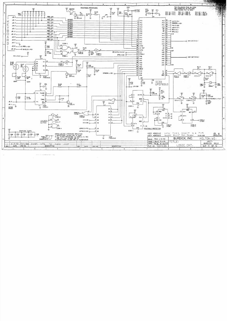
7.1.3
Microprocessor
lC33 is
a
NEC7B310
microprocessor
which
has
4
analog to digital
converters,
3
timers,
DMA circuitry,
serial l/O,
and
peripheral
interface
ports
built
in.
The
microprocessor
controls
the timing
of data
acquis-
ition, handles
input from the front
panel
keyboard, and
sends
the
appropriate output to the
LCD and
thermal
printhead.
A
thermister
provides
temperature
information
to
the
microprocessor,
which can
shut
down
the system
if
the
printhead becomes too warm.
The
system
clock
originates
from
Y1,
a 12MHz
crystal.
The
signal
is
buffered by
lC39 and
lC41
before
being
applied
to
the microprocessor.
lC29
is
the
system
ROM, which contains the operating
pro-
granr
for the microprocessor. lC30
provides
tempor-
ary RAM
storage
for data and
processor
commands.
lC31
latches address
lines A0-A7 when the ALE
signal
from the
microprocessor is
applied at pin
11.
lC2B
produces
an
enable
signal
for the
liquid
crystal
display
when
the
appropriate
address
is
presented
on
lines A13-A15.
7.1.4
Keyboard Interface
Pull-up
resistors in
RN3
provide
+5V
to the keyboard.
before
being
applied
to
pin
3 of
1C37.
A high
from
P37
causes
the motor to stop. Q12
is
the
motor current
driver,
which
is
driven
by the output at
pin
6 of
1C37.
R101
provides
short
cicuit
protection.
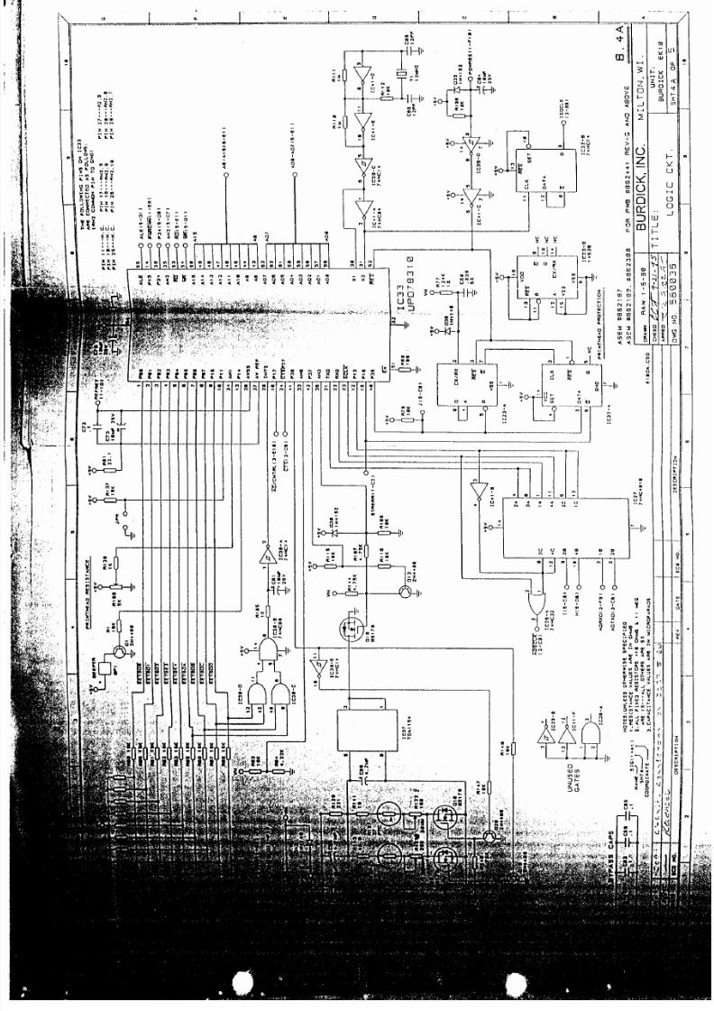
7.1.5a Motor Control
(Revision
G)
The
paper
drive can
run
at either 2Smm/sec or
50mm/
sec.
Field
effecttransistors
Q17
and
Q16
selecteither
the
25mm/sec
potentiometer R121 or the S0mm/sec
potentiometer
R122,lf
the S0mm/sec
speed
is select-
ed,
the
50MM/25MM signalfrom
the microprocessor
is
high.
lC39-E
inverts
this
signal so that
the base
of
Q20
is
driven
low
and
the base of
Q19
is driven high.
This
in
turn
causes
the
gate
of
Q16
to
go
high
and the
base
of
Q17
to
go
low.
The
50mmlsec
potentiometer,
R'122, is
thereby
selected.
lf the
2Smm/sec
speed
is
selected,
the
50MM/25MM
signalgoes
low and the
opposite action takes
place
resulting in
Q17
turning
off and
Q17
turning
on which selects the 2Smm/sec
potentiometer,
R121.
lC37
provides
the
constant
speed
control.
The
micro-
processor
(1C33)
turns
the
motor
on
and off
via
the
PAUSE/RUN
signalfrom
its P37
line. To
turn
the mo-
tor on,
the
signal is brought low
and inverted by
Q13
before being applied to
the
gate
of
Q18.
When the
T
F
I
T
q

8/20/2019 MANUAL SERVICIO EKG BURDICK EK10.pdf
http://slidepdf.com/reader/full/manual-servicio-ekg-burdick-ek10pdf 26/39
l#+.¡.1;
¡1&r+9,
r:'
lri.rl.:.i.i
r'l
l¡i;.¡1.1:'
detector
circuitry,
which
is
comprised
of lC23
and
1C32.
The
falling
edge
of
the
strobe triggers
one-shot
lC23 and
is
the D input for
flip flop
1C32.
lf the strobe
pulse
is less
than 2.0ms,
pín
2 of
lC32
is high when
pin
7 of lC23
returns
high, and
the
output
at
pin
6
of
lC32
remains
low.
lf
the strobe
pulse
is
longer than
2.0ms,
pin
2 of
lC32
is
low when
lC23 times out.
This
causes
pin
6
of
lC32
to
go
high,
sending the STRERR
signal
to
P16 of the
microprocessor
and
to
the strobe
inhibit circuitry.
A
reset signal
is applied at
pin
1 of
lC32 during power up
to ensure
that
the
printhead
is
not
strobed
during
this
time.
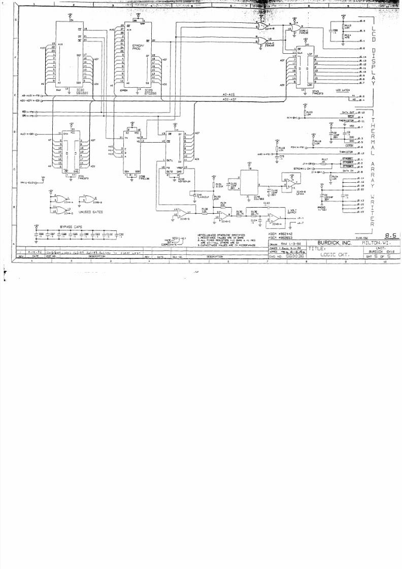
7.1.7 LCD
Interface
1C26, 1C43, and
lC44
provide
the
interface between
the
microprocessor
and the
liquid crystal
display.
The
A1
address
line to the
LCD is
high for read
operations
and
low
for write
operations. The A0
address
line high
for data and low for
the instruction
mode.
The
LDO-
LD7
data lines
interface
with lC43
during
a write.
During
a
write
operation,
the output at lC44-8,
pin
4,
is high.
This signal
causes
data to be clocked
into
1C43.
When the
output
from lC44-B
returns low,
pin
B
of
lC26-C
goes
low
to
latch
the
data
into
the
LCD.
The liquid crystal
display
has
an
internal
controller
-'jNF&MF-''"

8/20/2019 MANUAL SERVICIO EKG BURDICK EK10.pdf
http://slidepdf.com/reader/full/manual-servicio-ekg-burdick-ek10pdf 27/39
EK
1 0
ElectrocardiograPn
I
t
t
I
I
d
I
I
I
r-------l
II
t
|
,\*
|
I
::
I
I
5;
I
t1
:+
l-
'.

8/20/2019 MANUAL SERVICIO EKG BURDICK EK10.pdf
http://slidepdf.com/reader/full/manual-servicio-ekg-burdick-ek10pdf 28/39
Service
Manuat
7.1.10
EK10
PCB Block
Dlagram
é
8b
Eü

8/20/2019 MANUAL SERVICIO EKG BURDICK EK10.pdf
http://slidepdf.com/reader/full/manual-servicio-ekg-burdick-ek10pdf 29/39
8 SCHEMATICS
AND
COMPONENT
DIAGRAMS
8.1 POWER
SUPPLY
CIRCUIT
SCHEMATIC
8.2 INPUT C¡RCUIT
SCHEMAT¡C
8.2A
INPUT C¡RCUIT SCHEMATIC
(Rev.
D
and
after)
8.3
INPUT CIRCUIT
SCHEMATIC
(continued)
8.4
LOGIC
CIRCU¡T
SCHEMATIC
(Rev.
F
and
below)
8.4A
LOGIC CIRCUIT
SCHEMATIC
(Rev.
G
and
after)
..'-iffi
.,,'l*.ffiH
8.5
8.6
LOGIC
CIRCUIT SCHEMATIC
(continued)
,
K10 PCB
COMPONENT
DIAGRAM
(prior
to
Rev.
D)
'
a1:
I
I
I
I
I
I
8/20/2019 MANUAL SERVICIO EKG BURDICK EK10.pdf
http://slidepdf.com/reader/full/manual-servicio-ekg-burdick-ek10pdf 30/39
I---1.;
-
g^Tt
-
1e.5v
-
ñICAI]
n-
t8
,-_í"__F_3
¡q[.:i*J-:
-i
e+ov
)d
T\
30cra
¡ teCV
1
s.¡-1c
i
J
-
-t
D.0
sFs03
5.1rK
E
lF11€
'1'e.¿€
?s
'l'roor
RI
S.
r1K
li,
lN+148
--iG-
'C+
.
lfJS¿13
, LF:
¡-
t
llF6
|¿<
I
tcF
¿5v
.T\
I
l-o
FR:ñr.-c8l
cs
r00f
T
,) ¡5t)
.G
Iq
R +
1l+¡4€
fi
ers
v
¡K
I
10K
t0K
Fé
L.7
X
I
I
I
t_
=¿.d
l
r*
I
I
:._
lcH
R13
;
-8'5r'I
.¡
I*.
T.
BURDIC I1ILTON,
UI
.
i
I
I
i
I
I
1.7s
T
_1
¡lFzs
ll cK
I
D10
AY¿O'
I€fES¡ I}LE.SS
OT¡€A 'ISE SF€ClFI:
l.F€S¡sTacE
v^u-€s
^,R€
IN Ors
¿.^-L FfxED R6S¡SIORS
> C
*t6
e
.1
fÉtr
^Re
tz---^U- of]-€es ¡rlÉ SZ
3. C-p^C¡iaG
VILES
^E
Iil
ñlCtCFR,'is
8.7
Igl
1-^1
t
N^.€J
I I
94f.J
I
CÍUOIT¡^E
-'
ASE'1
cÉsfRrPf
s¡
C4
al+400
.L?
ii]ol-e *
01
sRso
3
MASTIR
RTVIS
ON
TABLT
gtut
OATE
a6l
órt
fE
DESCRIPTION
1
5013
9
/2" /s5
?
1
2
I
0
1
4V
rs0{q
\
,
l0 -{si
B
z
L
I
SLt
Lco
RAU L-5-30
TITLI:
I
suaüi&'ex:c
FOWER
SUPPLY CKT.
rG
i\o. 540C36
t5l
5ñt uri
Dr3-3t
^nE
Msa
'Ji:]ffi

8/20/2019 MANUAL SERVICIO EKG BURDICK EK10.pdf
http://slidepdf.com/reader/full/manual-servicio-ekg-burdick-ek10pdf 31/39
+0s E
[LtIa-e€Fs
s^l _-s
R+5
FSo
5. EK
13<
+
o.lt
o.tt
t
I
I
I
I
l
I
t
c36
¿r0PF
u
tI
ti
tl
ti
f
-J
-'
.11
rr
I
I
;
I
I
_l
tcra
7
+Er7
':¡
l
TL-oA40¡
G
r33<
o. rtl
'R3a
Delt
R+3
3|]{
+
@{rPo_
€$
,l
rh
I
il
x
rl
ü
R+t
Á
csa
al
I
+
5
LE^ C^A-E
L€TECfCR
.€]SVI
o
R40
¿cK
ICl3-a\
7+CA?
7
i
,
f€fES, L¡r€sS
CrTl€ilf
S€ SP€CIíIA
.G:sTAcE
V¡LI'ES
^'1€
N *rs
a,aI F¡xE
FÉsISfcFs
> c
ctst€
&
<1
fe
^FÉ
\Z---^LL
CrTr€FS M€
5Z
3.C^P^C¡T^¡€E
V4_Lt5
^ÁÉ
¡N
ñIC'CFAAA¡S
AsEfl
r86e++a
,
gr3t91
.
StLioo
R+a
a1
lM =
F
F--____?_€.s.svr
,48
f-"**o
*ir
J'
rT:P
V
:.v
v
,
gtl
r
ol ErcE.csu
L
rrulN
RA'J
L-5-90
EURDICK,
INC.
¡ILTON,
wI
TITLtr
'
INPUT
CKT.
UNIT¡
Éux ls s
Dr.rG
No.
56 0 0 35
E
clJTFÍ
I
f
lRt
|3.
T
I
r:z
FSS
+s3<
O
OJTRJT
I
5A
I
85l 3-F3
)
''''
s¡cl
t-^ ,
Ne€J
I
I
gíf.¿
)
fmINAfEJ
0rf-f¡ a¡t
t
i15l

8/20/2019 MANUAL SERVICIO EKG BURDICK EK10.pdf
http://slidepdf.com/reader/full/manual-servicio-ekg-burdick-ek10pdf 32/39
¿Cf,
r
65
r
3-rt ro_:g
srfJ'F3r^,ii
I'a
9
i5r
l-tr(
z
,./"'
o.c.
BtoctI¡6
c^r^ctfor
g'
Crg
't
r
g
afé
qtÁcú t
ñr
2¡
f.
ar
'LO6'CJ
432
o¡
5
2
ñ..8€
A55
2At
C^L
PULSÉ
GEÑ F^IOñ
'lutJ
Ol.
zdr.te
LOw. @
2
3,¡rt
u
Á15
lcl5
-^
,.HCa2
¡ct a
7.HCa73
cc¡lFcL
L^fcx
^s€v
8862i42
,
gbl
rz-t
,
3gz-t"o
AsEv
aa62653
,
6ál
r¿q
(NOrE:
rHlS
SHE€T IS ÉOR
rE624'
I REV-O ANO
LATÉF )
oa
QA
t4Hcr
¡.
L
c4l
- u
r¡
,.
[-
tl
;ll;tl
?,1
---.{
:
6l
I
;tl
;l
-'i
I
I
IC6
?
I
I
E
N
T
t\
P
U
T
-&
áv :
F36
FlÉ
1 l
s
CH
r1l
r
z
I'
I.."
"T
2.a"t
*
lr
5
LÉ^O
C^6L€
0Éf€CiOñ
r{+r5z
5 6(
I -^r
I
N^ÉJ
t I
sxft-
)
cco8ot¡^f€
J
ti
ñOt€5:UNLE5S
OrH€¡rl5E SFECIF aO
r.REs Sf^rCE
v^LU€s
^A€
¡N
CB6
:.^ L Élx€o
AÉs¡stcAs
,fa
oM
<r
<6
^ñE
rz---^LL
Oft€RS
^ñE
5t
l.c^P^c¡r¡{cE
vaLu€s
^Áé
JN
,¡cñoF^F¡OS
a
.2A
€
l sa. cso
BURDICK,
lNC.
MILroN. wI
AUFO¡CK ÉKIg
I
ILtr:
INPUÍ CKT
a).r-)
iJ3i¿1 165(11
lro -o
^sLts
-:-
owG No.
564436
s¡i
2A
oe

8/20/2019 MANUAL SERVICIO EKG BURDICK EK10.pdf
http://slidepdf.com/reader/full/manual-servicio-ekg-burdick-ek10pdf 33/39
PRIMn<^o
REslsT^¡(:
TI-€ FCI.LOJ¡¡G
PI}6
O.¡
rc='
^.RÉ
CI$€CTA
^S
FO-LOtiSl
Ifo€
@if(N
P¡Ñ
TO
B¡DI
F81
t0.Í
8.
PtN
?7---8.9
8/20/2019 MANUAL SERVICIO EKG BURDICK EK10.pdf
http://slidepdf.com/reader/full/manual-servicio-ekg-burdick-ek10pdf 34/39
F¡€
t 00K
10K
I off
-tr-,
PIil
e3---S€,A
P¡N
eS---ñ€.7
f**
| /
..6.+
G.3
s
G.2
¡
.5.1
B
.t.rl
O
.8.10
A
..E.s
R
.'.a
-l
pc
o
Pta
P04
4eaa
PC7
Pr0
l:J
All
-l
l Pl+
ALE
A\e
F
tñ
At5
A13
Alz
^11
Ar0
N)7
^¡6
^ts
AIl+
A.c:l
^12
All
^¡0
^Lgts-01,
ERS:ñ|
t-ÉB)
P34
{
s-Ett
l
a€t 5-c7 t
úrs-€r r
ñ(s-Drl
A1S
D
*'z
*-1
|
*."
.-----€r
ffii
-Esl
|
..6.
a
,
---{
grra_-ot
-Fa }
vlrf
r-€t0
)
R
00
1 . S(
RÉ
t0K
F84
+.á<
15¡err
AVSS
AV
fdF
¡NTA
P36
NO
A^¡3
FD(}
Pt3
Pt6
€-^1s{5-É
)
^-D0-^ltt
5-€r
)
\,,1{
I
allD@
R 106
10K
)Q,
Rt07
10K
ill
p:s
IC+r
-A
7
+'c0+ 7 +CL+
'-l
L*
I5*-T
tñ+r5¿
lc+L-c
7
IC39-D
2
,'r'
1 off
-La
8.4
c8+
IC+ -S
=
+c
3e
4
te7
7
+€,10L6
DAIA
UNUSED
7L<J+
I
=
RIMF€A.O PFOTÉEi:O¡
ASaY
'86e++¿
Asɡ1
'86e553
ñITES¡
t¡.r-ESS
OfF€ryIS€
SF€af F E
,R€SISTA\C¿
v^Lt-ES
^FE
fN o+ts
a.Al. FI)€D RESISÍCFS
>10
CFi€
&
¿1
f€6
^É.
t'/.---a-L
ofl€Rs
aFE
s¿
3.C*^CIT^JG
VILES
AF€ IN
N¡CRCFAR^¡S
IC33
UPDZ831
O
I
Lñrot+
.^
PATE€
-Ae
fmc¡
OJT
VDD
6
d13-rc
o
i 9*
1^
auu
l-11
rc
juo
I
lvssl
el
r +538
BURDICK,
INC.
HILTON.
wI
tuw
RAW
1-5-30
TITLf
'
LOGIC
CKT.
UNIf¡
BURDICK
EKlO
¡:t
t^
^:
s'-
DUG
NO. 560O
8/20/2019 MANUAL SERVICIO EKG BURDICK EK10.pdf
http://slidepdf.com/reader/full/manual-servicio-ekg-burdick-ek10pdf 35/39
:.i itlr'1
;r.:.r
j.
-.r-
'-':',i1:,
8/20/2019 MANUAL SERVICIO EKG BURDICK EK10.pdf
http://slidepdf.com/reader/full/manual-servicio-ekg-burdick-ek10pdf 36/39
.8.3
.8.
r
L
C
D
1i
D
I
S
r-
L
Y
.E. t3
.É,
r?
-8.
10
,t.9
.8,8
)
IC+3
7.+873
Lr¡
L^TOi
n#rsToR
I
L
R11/
-STGT*"2.
r
^8-A1Sf
+-FS I
ADo -^ 7 f
+-ES
)
f}€F-ilsrcR_.a.
1r I
Q
="co
H
í-_---T-_F
ñ IÉ¡ t-
.Á/
'T.
i-¡¡rc
-l-
. 1
n
Y te |
C\¡Il
T1
nRlls
+
I
N,.¿.s
lf
U
toK
esrr.-rarc--i-----S*.e.s
A
^¡€
(
+-F8 )
7+€r38
- cea
J-ca I"o
I.=
*cs
-Lca-¡
lc,,¿
Icso
.t
¿
ñITES¡ tl.r-ESS
OnGvIsÉ
SP€CIFIED
1.RÉs¡5'^¡€
vatlEs
Af,É
lN
Or€
?. -L ÉIX6
RÉS¡sTCFS
>:0
c}{"6 &
<
r€G
^É
t),,---N-L
Crffgs
^F€
SZ
3,C¡P^Cri{€€
V&ES ¡AÉ
iN tsICRF^-RAIIS
10f
6r
A
Y
lA
R
I
T
E
R
rjl-\s
i:i__.¿:,*."
=
u¡lu=eu b^
|
r>
QYpaqq
.rtrc
=
S¡C{
1
-^1
|
NA€J
I f
gÍr¿
)
LIGD¡N^TE
J
I
8.5
SHTSoFS
i
r
;-=T
rcao
=
L5l¿¿J
E
o-K
l¡7
IT
¡
tl
DO
iI
l
tL_
-Do
f,uw
RAu
1-3-e0
|
BURDICK,
lNC.
TILTON,WI.
TITLE:
LCCTC CKT.
Dlrc
¡ro.
560 036
aTE
|
ÉCúv r€.
I
D€SCAIPTIO{

8/20/2019 MANUAL SERVICIO EKG BURDICK EK10.pdf
http://slidepdf.com/reader/full/manual-servicio-ekg-burdick-ek10pdf 37/39
I
t*
"
rr-J..r..r.r.,,.
-l
.¡q]lillatÉrt+lt*tt¡li¿lt*l
I
vri$l4mk[{fll{t,t¡l
, L
}il:T::"i
In
Mffiffi#_Cp
Éqtuitr*'1
_.+q'"...l [] []"[]ll
[ltl
ktr--qr-Br,rrfiEtifll
*,s
t'#
lil''l{'1.]
llrl
tll_L
HFll$
-?
ffitl
ür¡lm
ll
:__l
ILX
{ lLl ill
t'
'l]*[]ltr
[1[{,.ffiHm-
HeF?ti'
trtrrt
't{ü$$(
Nffi
I
..,-,-

8/20/2019 MANUAL SERVICIO EKG BURDICK EK10.pdf
http://slidepdf.com/reader/full/manual-servicio-ekg-burdick-ek10pdf 38/39
:HKEO
I
TITLE:
owG
No. I
(FEV-O
& AAOVE)

8/20/2019 MANUAL SERVICIO EKG BURDICK EK10.pdf
http://slidepdf.com/reader/full/manual-servicio-ekg-burdick-ek10pdf 39/39
ÍU.flr-:.-n
f-f
-vffitl
1..¡¡tffir--'ll
xl
A-FñElFE.___,nl
| |
i i
v^:;:ii;;|i-jjj-1
r-rr.- | |
I
i
Ci Car+r?ñ-
r-"--l,.;¡
l.....ñ
l1
l^
il
L-j-
-
rw-: