Embed Size (px)
Citation preview

Level 1 and 2 Service Manual6809511A13-O
MOTORAZR2 V8
GSM 850/900/1800/1900 MHz EDGE, GPRS

MOTOROLA and the Stylized M Logo are registered in the US Patent & Trademark Office. All other product or service names are the property of their respective owners.
The Bluetooth trademarks are owned by their proprietor and used by Motorola, Inc. under license.© Motorola, Inc. 2007.All rights reserved.
Mobile Devices Business,Sawgrass International Concourse789 International ParkwayRoom S2C Sunrise, FL 33325-6220
6809515A95-O July 18, 2007 3
Level 1 and 2 Service Manual Contents
ContentsIntroduction . . . . . . . . . . . . . . . . . . . . . . . . . . . . . . . . . . . . . . . . . . . . . . . . . . . . . . . . . . . . . . . . . . . . . . . . . . . . . . . . . 5
Product Identification . . . . . . . . . . . . . . . . . . . . . . . . . . . . . . . . . . . . . . . . . . . . . . . . . . . . . . . . . . . . . . . . . . . 5Product Names . . . . . . . . . . . . . . . . . . . . . . . . . . . . . . . . . . . . . . . . . . . . . . . . . . . . . . . . . . . . . . . . . . . . . . . . 5Product Changes . . . . . . . . . . . . . . . . . . . . . . . . . . . . . . . . . . . . . . . . . . . . . . . . . . . . . . . . . . . . . . . . . . . . . . . 5Regulatory Agency Compliance . . . . . . . . . . . . . . . . . . . . . . . . . . . . . . . . . . . . . . . . . . . . . . . . . . . . . . . . . . . 5Computer Program Copyrights . . . . . . . . . . . . . . . . . . . . . . . . . . . . . . . . . . . . . . . . . . . . . . . . . . . . . . . . . . . 6About This Service Manual . . . . . . . . . . . . . . . . . . . . . . . . . . . . . . . . . . . . . . . . . . . . . . . . . . . . . . . . . . . . . . 6Warranty Service Policy . . . . . . . . . . . . . . . . . . . . . . . . . . . . . . . . . . . . . . . . . . . . . . . . . . . . . . . . . . . . . . . . . 7Parts Replacement . . . . . . . . . . . . . . . . . . . . . . . . . . . . . . . . . . . . . . . . . . . . . . . . . . . . . . . . . . . . . . . . . . . . . 7
Specifications . . . . . . . . . . . . . . . . . . . . . . . . . . . . . . . . . . . . . . . . . . . . . . . . . . . . . . . . . . . . . . . . . . . . . . . . . . . . . . 9Product Overview . . . . . . . . . . . . . . . . . . . . . . . . . . . . . . . . . . . . . . . . . . . . . . . . . . . . . . . . . . . . . . . . . . . . . . . . . . . 11
Features . . . . . . . . . . . . . . . . . . . . . . . . . . . . . . . . . . . . . . . . . . . . . . . . . . . . . . . . . . . . . . . . . . . . . . . . . . . . . 11General Operation . . . . . . . . . . . . . . . . . . . . . . . . . . . . . . . . . . . . . . . . . . . . . . . . . . . . . . . . . . . . . . . . . . . . . . . . . . . 15
Controls, Indicators, and Input / Output (I/O) Connections . . . . . . . . . . . . . . . . . . . . . . . . . . . . . . . . . . . . 15Battery Function . . . . . . . . . . . . . . . . . . . . . . . . . . . . . . . . . . . . . . . . . . . . . . . . . . . . . . . . . . . . . . . . . . . . . . 19Operation . . . . . . . . . . . . . . . . . . . . . . . . . . . . . . . . . . . . . . . . . . . . . . . . . . . . . . . . . . . . . . . . . . . . . . . . . . . . 19
Tools and Test Equipment . . . . . . . . . . . . . . . . . . . . . . . . . . . . . . . . . . . . . . . . . . . . . . . . . . . . . . . . . . . . . . . . . . . . 21Disassembly . . . . . . . . . . . . . . . . . . . . . . . . . . . . . . . . . . . . . . . . . . . . . . . . . . . . . . . . . . . . . . . . . . . . . . . . . . . . . . . . 22
Removing and Replacing the Battery Cover and Battery . . . . . . . . . . . . . . . . . . . . . . . . . . . . . . . . . . . . . 22Removing and Replacing the Subscriber Identity Module (SIM) . . . . . . . . . . . . . . . . . . . . . . . . . . . . . . . . 24Removing and Replacing the Rear Housing . . . . . . . . . . . . . . . . . . . . . . . . . . . . . . . . . . . . . . . . . . . . . . . . 25Removing and Replacing the Transceiver Board Assembly . . . . . . . . . . . . . . . . . . . . . . . . . . . . . . . . . . . . 34Removing and Replacing the Antenna . . . . . . . . . . . . . . . . . . . . . . . . . . . . . . . . . . . . . . . . . . . . . . . . . . . . 37Removing and Replacing the Keypad . . . . . . . . . . . . . . . . . . . . . . . . . . . . . . . . . . . . . . . . . . . . . . . . . . . . . 39Removing and Replacing the Flip Assembly . . . . . . . . . . . . . . . . . . . . . . . . . . . . . . . . . . . . . . . . . . . . . . . . 46
Subscriber Identity Module (SIM) and Identification . . . . . . . . . . . . . . . . . . . . . . . . . . . . . . . . . . . . . . . . . . . . . . . 77SIM Card . . . . . . . . . . . . . . . . . . . . . . . . . . . . . . . . . . . . . . . . . . . . . . . . . . . . . . . . . . . . . . . . . . . . . . . . . . . . 77Personality Transfer . . . . . . . . . . . . . . . . . . . . . . . . . . . . . . . . . . . . . . . . . . . . . . . . . . . . . . . . . . . . . . . . . . . 77Identification . . . . . . . . . . . . . . . . . . . . . . . . . . . . . . . . . . . . . . . . . . . . . . . . . . . . . . . . . . . . . . . . . . . . . . . . . 77
Troubleshooting . . . . . . . . . . . . . . . . . . . . . . . . . . . . . . . . . . . . . . . . . . . . . . . . . . . . . . . . . . . . . . . . . . . . . . . . . . . . 79Manual Test Mode . . . . . . . . . . . . . . . . . . . . . . . . . . . . . . . . . . . . . . . . . . . . . . . . . . . . . . . . . . . . . . . . . . . . 79Manual Test Mode Commands . . . . . . . . . . . . . . . . . . . . . . . . . . . . . . . . . . . . . . . . . . . . . . . . . . . . . . . . . . . 79Troubleshooting Chart . . . . . . . . . . . . . . . . . . . . . . . . . . . . . . . . . . . . . . . . . . . . . . . . . . . . . . . . . . . . . . . . . 81Programming: Software Upgrade and Flexing . . . . . . . . . . . . . . . . . . . . . . . . . . . . . . . . . . . . . . . . . . . . . . 83Part Numbers . . . . . . . . . . . . . . . . . . . . . . . . . . . . . . . . . . . . . . . . . . . . . . . . . . . . . . . . . . . . . . . . . . . . . . . . 83Exploded View Diagram . . . . . . . . . . . . . . . . . . . . . . . . . . . . . . . . . . . . . . . . . . . . . . . . . . . . . . . . . . . . . . . . 84Exploded View Parts List . . . . . . . . . . . . . . . . . . . . . . . . . . . . . . . . . . . . . . . . . . . . . . . . . . . . . . . . . . . . . . . 86Accessories . . . . . . . . . . . . . . . . . . . . . . . . . . . . . . . . . . . . . . . . . . . . . . . . . . . . . . . . . . . . . . . . . . . . . . . . . . . 89
1 and 2ContentsMOTORAZR 2 V86809515A95-O

4 July 18, 2007 6809515A95-O
Contents MOTORAZR 2 V8
6809515A95-O July 18, 2007 5
Level 1 and 2 Service Manual Introduction
IntroductionMotorola® Inc. maintains a worldwide organization that is dedicated to provide responsive, full-service customer support. Motorola products are serviced by an international network of company-operated product-care centers as well as authorized independent service firms.
Available on a contract basis, Motorola Inc. offers comprehensive maintenance and installation programs that allow customers to meet requirements for reliable, continuous communications.
To learn more about the wide range of Motorola service programs, contact your local Motorola products representative or the nearest Customer Service Manager.
Product IdentificationMotorola products are identified by the model number on a label usually located under the battery. Use the entire model number when inquiring about the product. Numbers are also assigned to chassis and kits. Use these numbers when requesting information or ordering replacement parts.
Product NamesProduct names are listed on the front cover. Product names are subject to change without notice. Some product names, as well as some frequency bands, are available only in certain markets.
Product ChangesWhen electrical, mechanical or production changes are incorporated into Motorola products, a revision letter is assigned to the chassis or kit affected, for example; -A, -B, or -C, and so on.
The chassis or kit number, complete with revision number, is imprinted during production. The revision letter is an integral part of the chassis or kit number and is also listed on schematic diagrams and printed-circuit board layouts.
Regulatory Agency ComplianceThis device complies with Part 15 of the FCC Rules. Operation is subject to the following conditions:• This device may not cause any harmful interference• This device must accept interference received, including interference that may
cause undesired operation
This class B device also complies with all requirements of the Canadian Interference-Causing Equipment Regulations (ICES-003).
Cet appareil numérique de la classe B respecte toutes les exigences du Règlement sur le matériel brouilleur du Canada.
1 and 2MOTORAZR 2 V86809515A95-O
6 July 18, 2007 6809515A95-O
Introduction MOTORAZR 2 V8
Computer Program CopyrightsThe Motorola products described in this manual may include Motorola computer programs stored in semiconductor memories or other media that are copyrighted with all rights reserved worldwide to Motorola. Laws in the United States and other countries preserve for Motorola, Inc. certain exclusive rights to the copyrighted computer programs, including the exclusive right to copy, reproduce, modify, decompile, disassemble, and reverse-engineer the Motorola computer programs in any manner or form without Motorola's prior written consent. Furthermore, the purchase of Motorola products shall not be deemed to grant either directly or by implication, estoppel, or otherwise, any license or rights under the copyrights, patents, or patent applications of Motorola, except for a nonexclusive license to use the Motorola product and the Motorola computer programs with the Motorola product.
About This Service ManualUse of this manual assures proper installation, operation, and maintenance of Motorola products and equipment. It contains all service information required for the equipment described and is current as of the printing date. Refer questions about this manual to the nearest Customer Service Manager.
Audience
This manual aids service personnel in testing and repairing V8 telephones. Service personnel should be familiar with electronic assembly, testing, and troubleshooting methods, and with the operation and use of associated test equipment.
Scope
This manual provides basic information relating to V8 telephones, and also provides procedures and processes for repairing the phones at Level 1 and 2 service centers including:• Unit swap out• Repairing of mechanical faults• Basic modular troubleshooting• Testing and verification of unit functionality• Initiate warranty claims and send faulty modules to Level 3 or 4 repair
centers
6809515A95-O July 18, 2007 7
Level 1 and 2 Service Manual Introduction
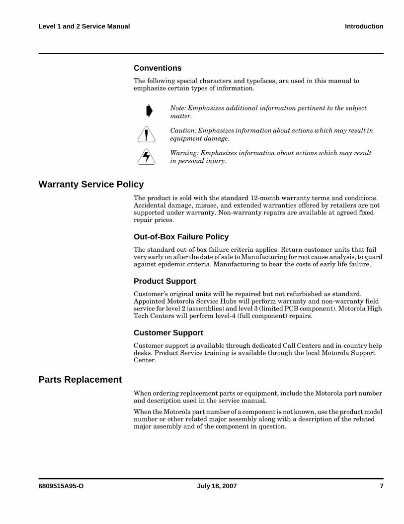
Conventions
The following special characters and typefaces, are used in this manual to emphasize certain types of information.
Warranty Service PolicyThe product is sold with the standard 12-month warranty terms and conditions. Accidental damage, misuse, and extended warranties offered by retailers are not supported under warranty. Non-warranty repairs are available at agreed fixed repair prices.
Out-of-Box Failure Policy
The standard out-of-box failure criteria applies. Return customer units that fail very early on after the date of sale to Manufacturing for root cause analysis, to guard against epidemic criteria. Manufacturing to bear the costs of early life failure.
Product Support
Customer’s original units will be repaired but not refurbished as standard. Appointed Motorola Service Hubs will perform warranty and non-warranty field service for level 2 (assemblies) and level 3 (limited PCB component). Motorola High Tech Centers will perform level-4 (full component) repairs.
Customer Support
Customer support is available through dedicated Call Centers and in-country help desks. Product Service training is available through the local Motorola Support Center.
Parts ReplacementWhen ordering replacement parts or equipment, include the Motorola part number and description used in the service manual.
When the Motorola part number of a component is not known, use the product model number or other related major assembly along with a description of the related major assembly and of the component in question.
➧ Note: Emphasizes additional information pertinent to the subject matter.
G Caution: Emphasizes information about actions which may result in equipment damage.
E Warning: Emphasizes information about actions which may result in personal injury.
8 July 18, 2007 6809515A95-O
Introduction MOTORAZR 2 V8
Replacement Parts Service Division (RPSD)
Order replacement parts, test equipment, and manuals from RPSD.
U.S.A. Outside U.S.A.
Phone: 800-422-4210 Phone: 847-538-8023
FAX: 800-622-6210 FAX: 847-576-3023
Website: http://businessonline.motorola.com
EMEA
Phone: +49 461 803 1404
Website: http://emeaonline.motorola.com
Asia
Phone: +65 648 62995
Website: http://asiaonline.motorola.com
6809515A95-O July 18, 2007 9
Level 1 and 2 Service Manual Specifications
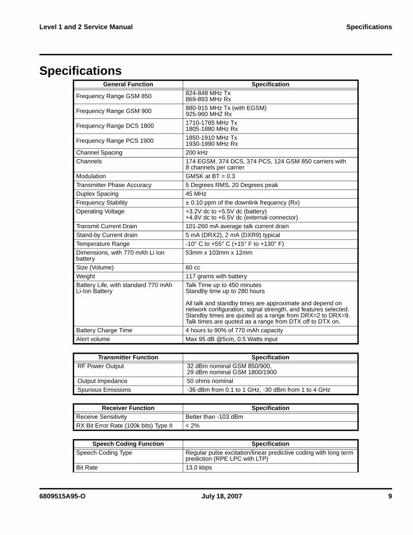
Specifications General Function Specification
Frequency Range GSM 850 824-848 MHz Tx869-893 MHz Rx
Frequency Range GSM 900 880-915 MHz Tx (with EGSM)925-960 MHZ Rx
Frequency Range DCS 1800 1710-1785 MHz Tx1805-1880 MHz Rx
Frequency Range PCS 1900 1850-1910 MHz Tx1930-1990 MHz Rx
Channel Spacing 200 kHzChannels 174 EGSM, 374 DCS, 374 PCS, 124 GSM 850 carriers with
8 channels per carrier
Modulation GMSK at BT = 0.3
Transmitter Phase Accuracy 5 Degrees RMS, 20 Degrees peakDuplex Spacing 45 MHz
Frequency Stability ± 0.10 ppm of the downlink frequency (Rx)
Operating Voltage +3.2V dc to +5.5V dc (battery)+4.8V dc to +6.5V dc (external connector)
Transmit Current Drain 101-260 mA average talk current drain
Stand-by Current drain 5 mA (DRX2), 2 mA (DXR9) typical
Temperature Range -10° C to +55° C (+15° F to +130° F)Dimensions, with 770 mAh Li Ion battery
53mm x 103mm x 12mm
Size (Volume) 60 cc
Weight 117 grams with batteryBattery Life, with standard 770 mAh Li-Ion Battery
Talk Time up to 450 minutesStandby time up to 280 hours
All talk and standby times are approximate and depend on network configuration, signal strength, and features selected. Standby times are quoted as a range from DRX=2 to DRX=9. Talk times are quoted as a range from DTX off to DTX on.
Battery Charge Time 4 hours to 90% of 770 mAh capacity
Alert volume Max 95 dB @5cm, 0.5 Watts input
Transmitter Function SpecificationRF Power Output 32 dBm nominal GSM 850/900,
29 dBm nominal GSM 1800/1900
Output Impedance 50 ohms nominal
Spurious Emissions -36 dBm from 0.1 to 1 GHz, -30 dBm from 1 to 4 GHz
Receiver Function SpecificationReceive Sensitivity Better than -103 dBm
RX Bit Error Rate (100k bits) Type II < 2%
Speech Coding Function SpecificationSpeech Coding Type Regular pulse excitation/linear predictive coding with long term
prediction (RPE LPC with LTP)
Bit Rate 13.0 kbps
10 July 18, 2007 6809515A95-O
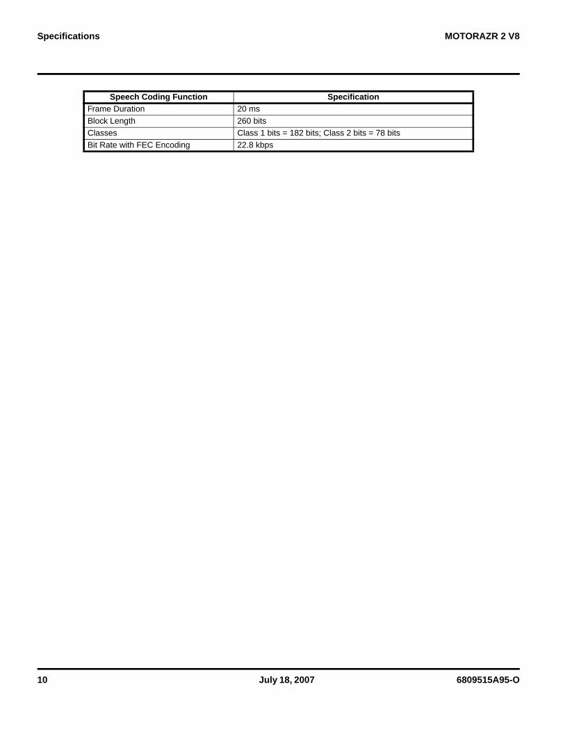
Specifications MOTORAZR 2 V8
Frame Duration 20 ms
Block Length 260 bits
Classes Class 1 bits = 182 bits; Class 2 bits = 78 bits
Bit Rate with FEC Encoding 22.8 kbps
Speech Coding Function Specification
6809515A95-O July 18, 2007 11
Level 1 and 2 Service Manual Product Overview
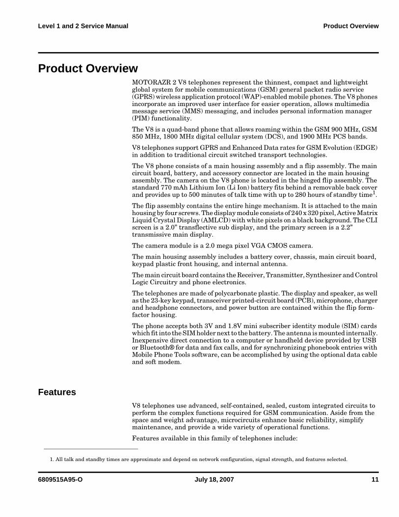
Product OverviewMOTORAZR 2 V8 telephones represent the thinnest, compact and lightweight global system for mobile communications (GSM) general packet radio service (GPRS) wireless application protocol (WAP)-enabled mobile phones. The V8 phones incorporate an improved user interface for easier operation, allows multimedia message service (MMS) messaging, and includes personal information manager (PIM) functionality.
The V8 is a quad-band phone that allows roaming within the GSM 900 MHz, GSM 850 MHz, 1800 MHz digital cellular system (DCS), and 1900 MHz PCS bands.
V8 telephones support GPRS and Enhanced Data rates for GSM Evolution (EDGE) in addition to traditional circuit switched transport technologies.
The V8 phone consists of a main housing assembly and a flip assembly. The main circuit board, battery, and accessory connector are located in the main housing assembly. The camera on the V8 phone is located in the hinged flip assembly. The standard 770 mAh Lithium Ion (Li Ion) battery fits behind a removable back cover and provides up to 500 minutes of talk time with up to 280 hours of standby time1.
The flip assembly contains the entire hinge mechanism. It is attached to the main housing by four screws. The display module consists of 240 x 320 pixel, Active Matrix Liquid Crystal Display (AMLCD) with white pixels on a black background. The CLI screen is a 2.0” transflective sub display, and the primary screen is a 2.2” transmissive main display.
The camera module is a 2.0 mega pixel VGA CMOS camera.
The main housing assembly includes a battery cover, chassis, main circuit board, keypad plastic front housing, and internal antenna.
The main circuit board contains the Receiver, Transmitter, Synthesizer and Control Logic Circuitry and phone electronics.
The telephones are made of polycarbonate plastic. The display and speaker, as well as the 23-key keypad, transceiver printed-circuit board (PCB), microphone, charger and headphone connectors, and power button are contained within the flip form-factor housing.
The phone accepts both 3V and 1.8V mini subscriber identity module (SIM) cards which fit into the SIM holder next to the battery. The antenna is mounted internally. Inexpensive direct connection to a computer or handheld device provided by USB or Bluetooth® for data and fax calls, and for synchronizing phonebook entries with Mobile Phone Tools software, can be accomplished by using the optional data cable and soft modem.
FeaturesV8 telephones use advanced, self-contained, sealed, custom integrated circuits to perform the complex functions required for GSM communication. Aside from the space and weight advantage, microcircuits enhance basic reliability, simplify maintenance, and provide a wide variety of operational functions.
Features available in this family of telephones include:
1. All talk and standby times are approximate and depend on network configuration, signal strength, and features selected.
12 July 18, 2007 6809515A95-O
Product Overview MOTORAZR 2 V8
• 240 x 320 262K TFT Main Display (2.2"), external display (2.0")• 2.0 megapixel VGA CMOS Camera (1600 x 1200 pixels)• Polyphonic Speaker• Messaging: SMS, MMS, WV• Audio CODECs: Windows WMA plus Janus DRM, MP3, AAC, AAC+, eAAC+,
WAV• Video: Capture/Playback, h.263, MPEG4 3GPP• Connectivity: Bluetooth® Class 2, USB-2.0 HS, Mobile Phone Tools, Over the
Air Sync (OTA)• Up to 512MB or 2GB on board memory
6809515A95-O July 18, 2007 13
Level 1 and 2 Service Manual Product Overview
Speaker Dependent Voice Activation and Voice Note Recording
Voice tags can be used for voice dialing up to 20 phone numbers in the phone book and for creating up to 5 voice shortcuts for menu items. The phone must be “trained” by the voice tag being read into the phone’s memory twice before it is recognized.
You can add voice tags to the phone’s memory using the usual name addition methods (i.e., via the phone book menu structure or with the shortcut editor).
V8 telephones also include a voice recorder that allows up to 2 minutes of personal messages to be recorded. This feature has a complete set of record, playback, and management tools that make it easy to store and maintain a list of personal memos.
Wireless Access Protocol (WAP) 1.1 Compliancy
In the WAP environment, access to the Internet is initiated in wireless markup language (WML), which is derived from hypertext markup language (HTML). The request is passed to a WAP gateway that retrieves the information from the server in standard HTML (subsequently filtered to WML) or directly in WML if available. The information is then passed to the mobile subscriber via the mobile network.
The V8 microbrowser can be configured for baud, idle timeout, line type, phone number, and connection type.
SIM Application ToolkitTM - Class 2
SIM Application Toolkit is a value-added service delivery mechanism that allows GSM operators to customize the services they offer their customers, from the occasional user who requests sports news and traffic alerts, to a high call time business user who receives stock alerts and checks flight times. Operators can now create their own value-added services menu quickly and easily in the phone. The customized menu will appear as the first menu and may be updated over-the-air with new services when customers request them.
➧ You cannot place or receive calls while adding voice tags to the phone’s memory.
➧ Because the GSM standard does not provide the option to store voice tags onto the SIM card, voice tags are added to the phone’s memory.
➧ Bitmap image data will download as text. If the image is larger than the screen, only part of the image will display.
➧ When the user receives a call while in browser mode, the browser will pause and allow the user to resume after completing the call.
14 July 18, 2007 6809515A95-O
Product Overview MOTORAZR 2 V8
Simplified Text Entry
There are three different ways to enter text using the phone keypad:• iTAP™ predictive text entry. Press a key to generate a character and a
dynamic dictionary uses this to build and display a set of word or name options. The iTAP™ feature may not be available on the phone in all lan-guages.
• Tap. Press a key to generate a character.• Numeric. The keypad produces numeric characters only. For some text areas
this is the only method available; for example, phone numbers.
Caller Line Identification
Upon receipt of a call, the calling party’s phone number is compared to the phone book. If the number matches a phone book entry, that name will be displayed. If there is no phone book entry, the incoming phone number will be displayed. In the event that no caller identification information is available, the Incoming Call message is displayed.
Other Features
Detailed descriptions of these and other V8 features can be found in the user’s guide.
➧ User must subscribe to a caller line identification service through their service provider.
6809515A95-O July 18, 2007 15
Level 1 and 2 Service Manual General Operation
General Operation
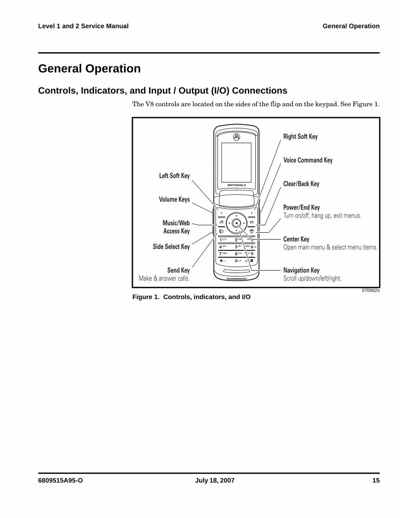
Controls, Indicators, and Input / Output (I/O) ConnectionsThe V8 controls are located on the sides of the flip and on the keypad. See Figure 1.
070062o
Figure 1. Controls, indicators, and I/O
Center KeyOpen main menu & select menu items.
Navigation KeyScroll up/down/left/right.
Voice Command Key
Clear/Back Key
Power/End KeyTurn on/off, hang up, exit menus.
Right Soft Key
Music/WebAccess Key
Volume Keys
Send KeyMake & answer calls.
Left Soft Key
Side Select Key
16 July 18, 2007 6809515A95-O
General Operation MOTORAZR 2 V8
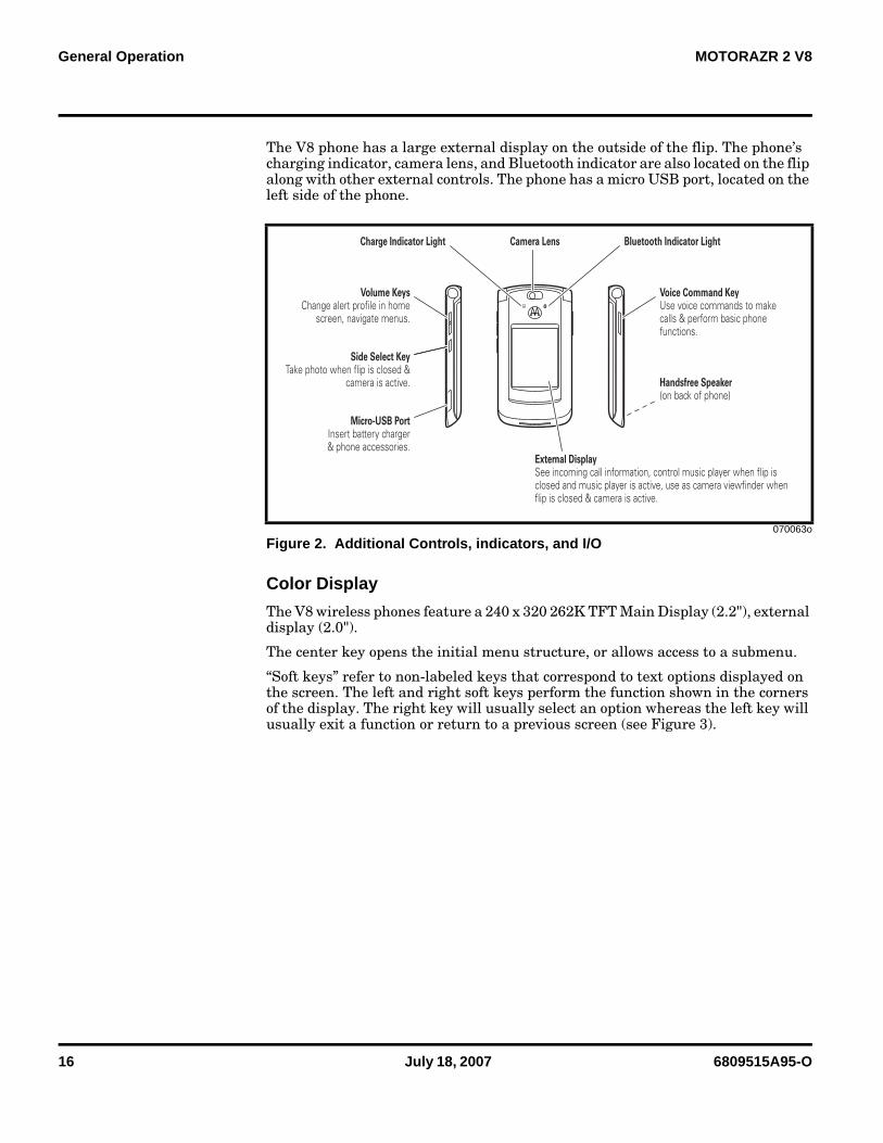
The V8 phone has a large external display on the outside of the flip. The phone’s charging indicator, camera lens, and Bluetooth indicator are also located on the flip along with other external controls. The phone has a micro USB port, located on the left side of the phone.
Color Display
The V8 wireless phones feature a 240 x 320 262K TFT Main Display (2.2"), external display (2.0").
The center key opens the initial menu structure, or allows access to a submenu.
“Soft keys” refer to non-labeled keys that correspond to text options displayed on the screen. The left and right soft keys perform the function shown in the corners of the display. The right key will usually select an option whereas the left key will usually exit a function or return to a previous screen (see Figure 3).
070063o
Figure 2. Additional Controls, indicators, and I/O
Volume KeysChange alert profile in home
screen, navigate menus.
Side Select KeyTake photo when flip is closed &
camera is active.
Camera Lens
External DisplaySee incoming call information, control music player when flip is closed and music player is active, use as camera viewfinder when flip is closed & camera is active.
Handsfree Speaker(on back of phone)
Micro-USB PortInsert battery charger& phone accessories.
Voice Command KeyUse voice commands to make calls & perform basic phone functions.
Charge Indicator Light Bluetooth Indicator Light
6809515A95-O July 18, 2007 17
Level 1 and 2 Service Manual General Operation
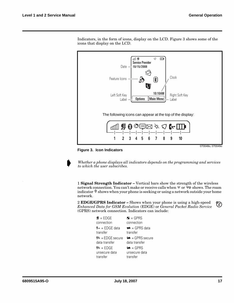
Indicators, in the form of icons, display on the LCD. Figure 3 shows some of the icons that display on the LCD.
1
1 Signal Strength Indicator – Vertical bars show the strength of the wireless network connection. You can’t make or receive calls when 0 or / shows. The roam indicator 1 shows when your phone is seeking or using a network outside your home network.
2 EDGE/GPRS Indicator – Shows when your phone is using a high-speed Enhanced Data for GSM Evolution (EDGE) or General Packet Radio Service (GPRS) network connection. Indicators can include:
070048o, 070049o
Figure 3. Icon Indicators
➧ Whether a phone displays all indicators depends on the programming and services to which the user subscribes.
, = EDGE connection
> = GPRS connection
5 = EDGE data transfer
< = GPRS data transfer
4 = EDGE secure data transfer
8 = GPRS secure data transfer
6 = EDGE unsecure data transfer
9 = GPRS unsecure data transfer
2 1061 3 984 5 7
Date
Clock
Left Soft Key Label
Right Soft Key Label
Service Provider10/15/2008
10:10AM
Options Main Menu
Feature Icons
The following icons can appear at the top of the display:
18 July 18, 2007 6809515A95-O
General Operation MOTORAZR 2 V8
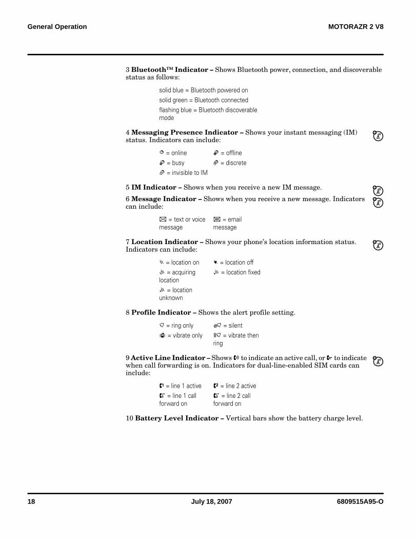
3 Bluetooth™ Indicator – Shows Bluetooth power, connection, and discoverable status as follows:
4 Messaging Presence Indicator – Shows your instant messaging (IM) status. Indicators can include:
5 IM Indicator – Shows when you receive a new IM message.
6 Message Indicator – Shows when you receive a new message. Indicators can include:
7 Location Indicator – Shows your phone’s location information status. Indicators can include:
8 Profile Indicator – Shows the alert profile setting.
9 Active Line Indicator – Shows X to indicate an active call, or Y to indicate when call forwarding is on. Indicators for dual-line-enabled SIM cards can include:
10 Battery Level Indicator – Vertical bars show the battery charge level.
solid blue = Bluetooth powered onsolid green = Bluetooth connectedflashing blue = Bluetooth discoverable mode
B = online E = offlineC = busy F = discreteD = invisible to IM
] = text or voice message
[ = email message
J = location on K = location offL = acquiring location
M = location fixed
I = location unknown
) = ring only O = silentS = vibrate only ( = vibrate then
ring
V = line 1 active W = line 2 activeZ = line 1 call forward on
a = line 2 call forward on
6809515A95-O July 18, 2007 19
Level 1 and 2 Service Manual General Operation
Battery Function
Battery Gauge
The telephone displays a battery level indicator icon in the idle screen to indicate the battery charge level. The gauge shows four levels: 100%, 66%, 33%, and Low Battery.
Battery Removal
Removing the battery causes the device to immediately shut down and any pending work (for example, partially entered phone book entries or outgoing messages) is lost.
OperationFor detailed operating instructions, refer to the appropriate User’s Guide.
➧ To ensure proper memory retention, turn OFF the phone before removing the battery.
G If the battery is removed while receiving a message, the message will be lost.

20 July 18, 2007 6809515A95-O
General Operation MOTORAZR 2 V8
6809515A95-O July 18, 2007 21
Level 1 and 2 Service Manual Tools and Test Equipment
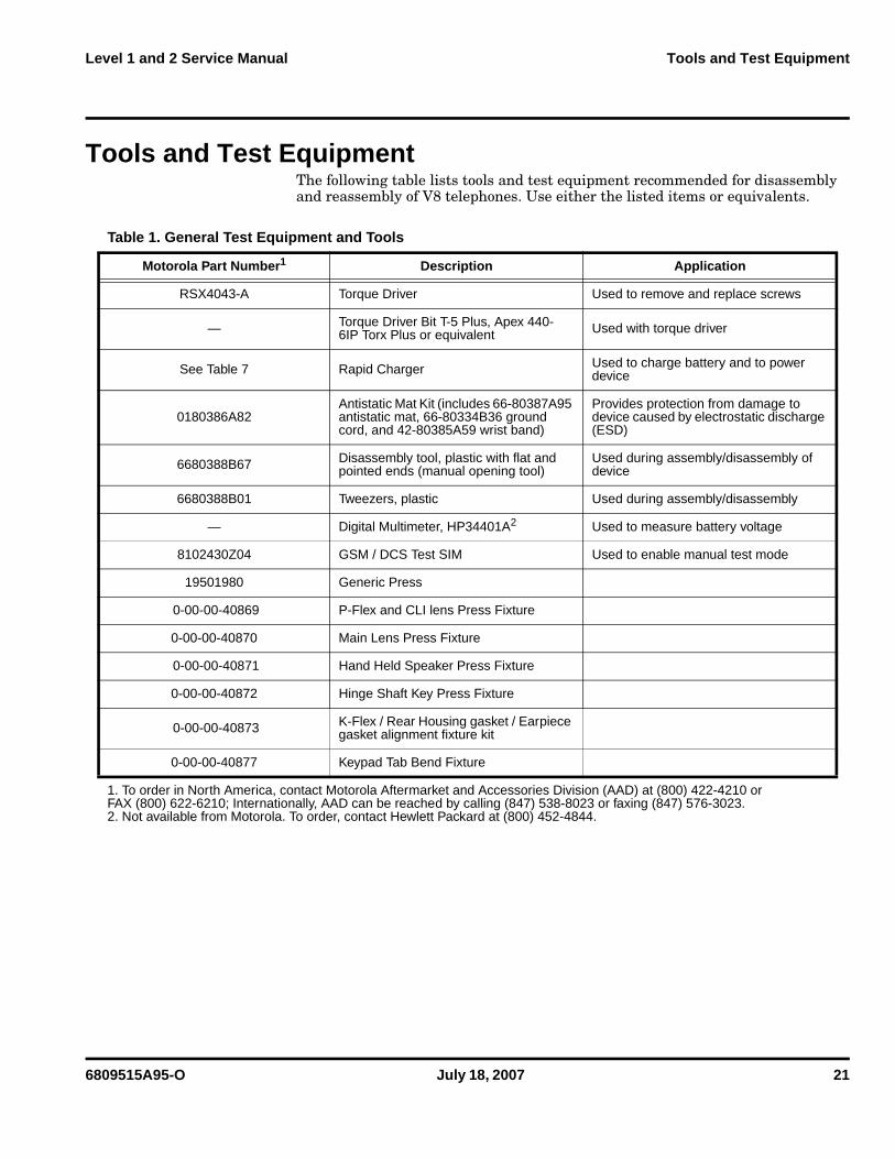
Tools and Test EquipmentThe following table lists tools and test equipment recommended for disassembly and reassembly of V8 telephones. Use either the listed items or equivalents.
Table 1. General Test Equipment and Tools
Motorola Part Number1 Description Application
RSX4043-A Torque Driver Used to remove and replace screws
— Torque Driver Bit T-5 Plus, Apex 440-6IP Torx Plus or equivalent Used with torque driver
See Table 7 Rapid Charger Used to charge battery and to power device
0180386A82Antistatic Mat Kit (includes 66-80387A95 antistatic mat, 66-80334B36 ground cord, and 42-80385A59 wrist band)
Provides protection from damage to device caused by electrostatic discharge (ESD)
6680388B67 Disassembly tool, plastic with flat and pointed ends (manual opening tool)
Used during assembly/disassembly of device
6680388B01 Tweezers, plastic Used during assembly/disassembly
— Digital Multimeter, HP34401A2 Used to measure battery voltage
8102430Z04 GSM / DCS Test SIM Used to enable manual test mode
19501980 Generic Press
0-00-00-40869 P-Flex and CLI lens Press Fixture
0-00-00-40870 Main Lens Press Fixture
0-00-00-40871 Hand Held Speaker Press Fixture
0-00-00-40872 Hinge Shaft Key Press Fixture
0-00-00-40873 K-Flex / Rear Housing gasket / Earpiece gasket alignment fixture kit
0-00-00-40877 Keypad Tab Bend Fixture
1. To order in North America, contact Motorola Aftermarket and Accessories Division (AAD) at (800) 422-4210 or FAX (800) 622-6210; Internationally, AAD can be reached by calling (847) 538-8023 or faxing (847) 576-3023.2. Not available from Motorola. To order, contact Hewlett Packard at (800) 452-4844.
1 and 2V86809515A95-O
22 July 18, 2007 6809515A95-O
Disassembly V8
DisassemblyThe procedures in this section provide instructions for the disassembly of V8 telephones. Tools and equipment used for the phone are listed in Table 1, preceding.
Removing and Replacing the Battery Cover and Battery
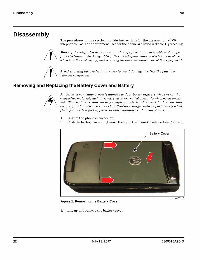
1. Ensure the phone is turned off.2. Push the battery cover up (toward the top of the phone) to release (see Figure 1).
3. Lift up and remove the battery cover.
G Many of the integrated devices used in this equipment are vulnerable to damage from electrostatic discharge (ESD). Ensure adequate static protection is in place when handling, shipping, and servicing the internal components of this equipment.
G Avoid stressing the plastic in any way to avoid damage to either the plastic or internal components.
EAll batteries can cause property damage and/or bodily injury, such as burns if a conductive material, such as jewelry, keys, or beaded chains touch exposed termi-nals. The conductive material may complete an electrical circuit (short circuit) and become quite hot. Exercise care in handling any charged battery, particularly when placing it inside a pocket, purse, or other container with metal objects.
v470113
Figure 1. Removing the Battery Cover
Battery Cover
6809515A95-O July 18, 2007 23
Level 1 and 2 Service Manual Disassembly
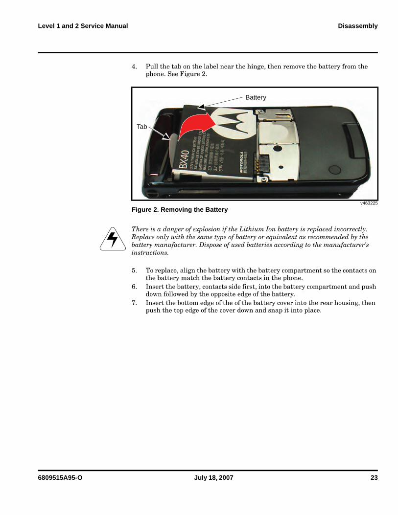
4. Pull the tab on the label near the hinge, then remove the battery from the phone. See Figure 2.
5. To replace, align the battery with the battery compartment so the contacts on the battery match the battery contacts in the phone.
6. Insert the battery, contacts side first, into the battery compartment and push down followed by the opposite edge of the battery.
7. Insert the bottom edge of the of the battery cover into the rear housing, then push the top edge of the cover down and snap it into place.
v463225
Figure 2. Removing the Battery
EThere is a danger of explosion if the Lithium Ion battery is replaced incorrectly. Replace only with the same type of battery or equivalent as recommended by the battery manufacturer. Dispose of used batteries according to the manufacturer’s instructions.
Battery
Tab
24 July 18, 2007 6809515A95-O
Disassembly V8
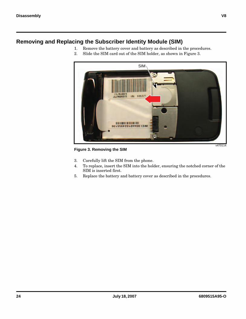
Removing and Replacing the Subscriber Identity Module (SIM)1. Remove the battery cover and battery as described in the procedures.2. Slide the SIM card out of the SIM holder, as shown in Figure 3.
3. Carefully lift the SIM from the phone.4. To replace, insert the SIM into the holder, ensuring the notched corner of the
SIM is inserted first.5. Replace the battery and battery cover as described in the procedures.
v470114
Figure 3. Removing the SIM
SIM
6809515A95-O July 18, 2007 25
Level 1 and 2 Service Manual Disassembly
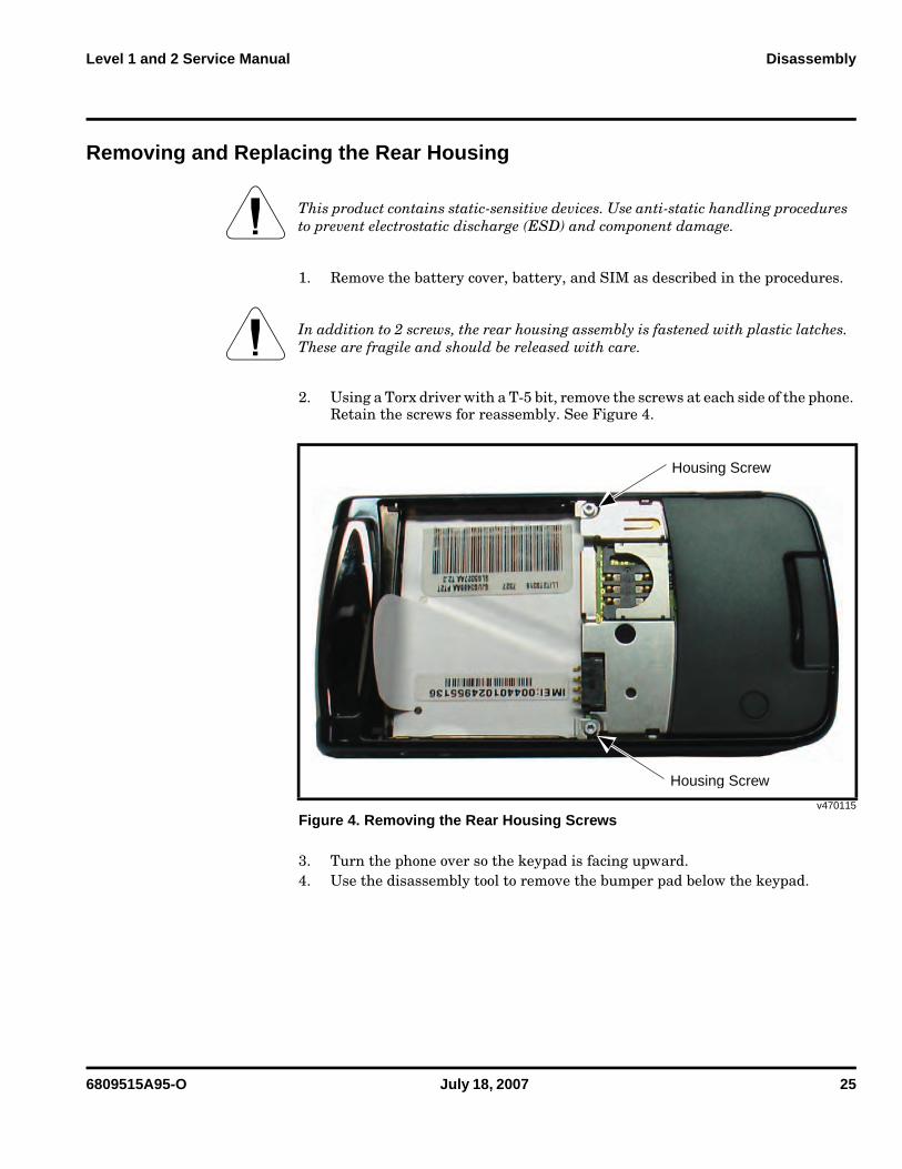
Removing and Replacing the Rear Housing
1. Remove the battery cover, battery, and SIM as described in the procedures.
2. Using a Torx driver with a T-5 bit, remove the screws at each side of the phone. Retain the screws for reassembly. See Figure 4.
3. Turn the phone over so the keypad is facing upward.4. Use the disassembly tool to remove the bumper pad below the keypad.
G This product contains static-sensitive devices. Use anti-static handling procedures to prevent electrostatic discharge (ESD) and component damage.
G In addition to 2 screws, the rear housing assembly is fastened with plastic latches. These are fragile and should be released with care.
v470115
Figure 4. Removing the Rear Housing Screws
Housing Screw
Housing Screw
26 July 18, 2007 6809515A95-O
Disassembly V8
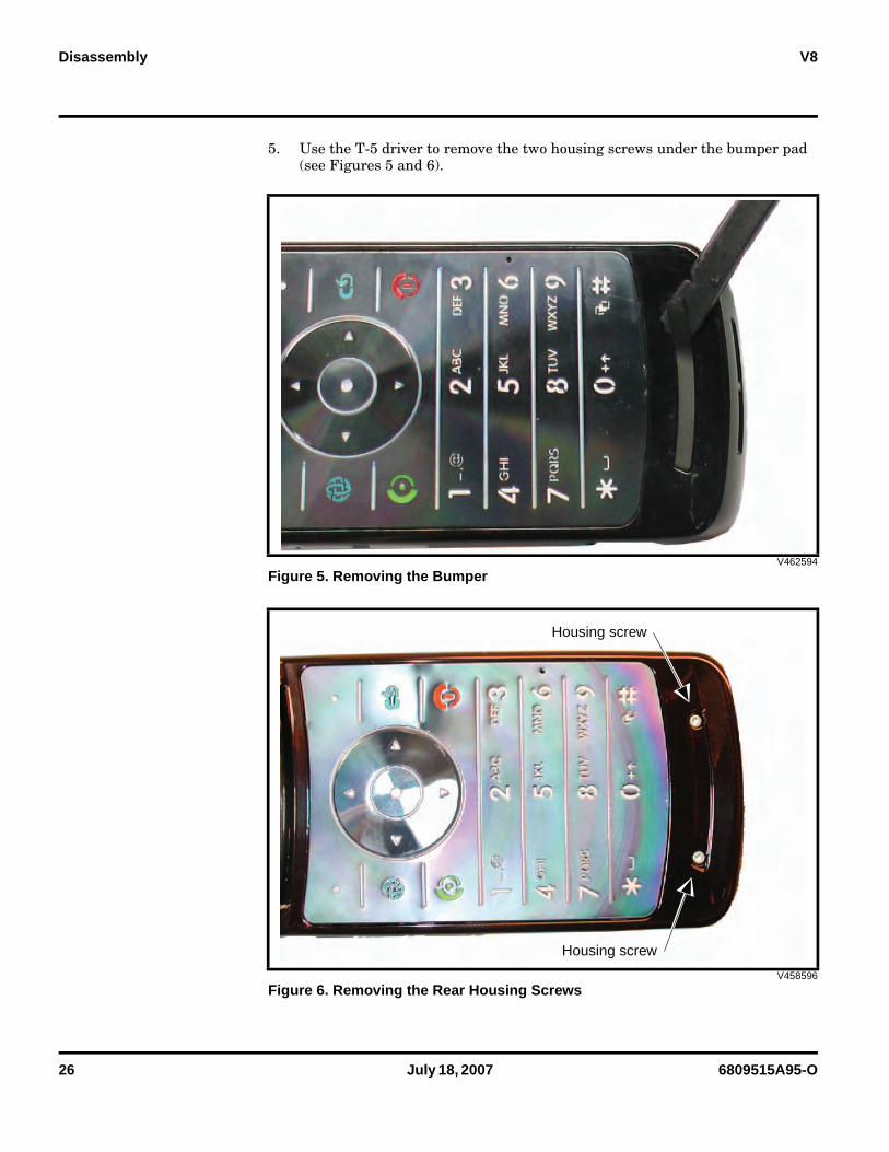
5. Use the T-5 driver to remove the two housing screws under the bumper pad (see Figures 5 and 6).
V462594
Figure 5. Removing the Bumper
V458596
Figure 6. Removing the Rear Housing Screws
Housing screw
Housing screw
6809515A95-O July 18, 2007 27
Level 1 and 2 Service Manual Disassembly
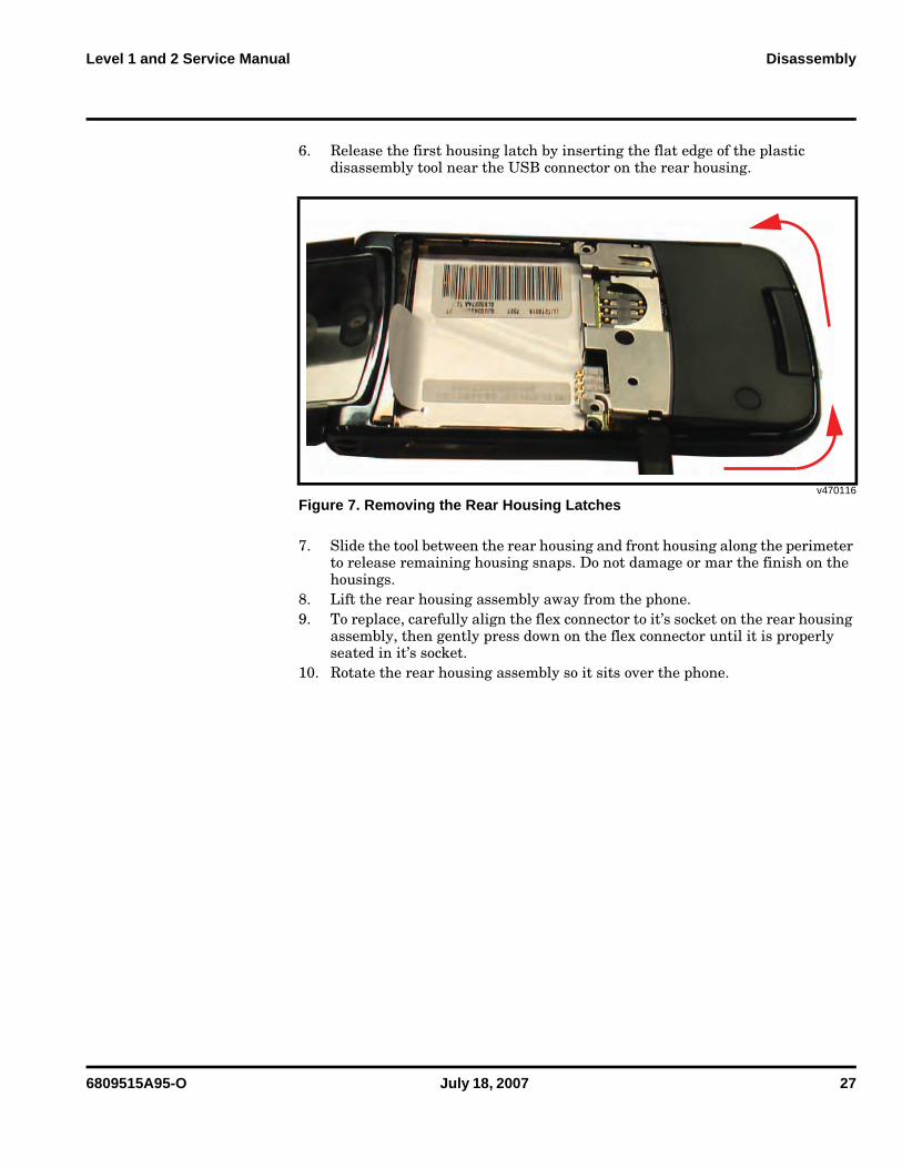
6. Release the first housing latch by inserting the flat edge of the plastic disassembly tool near the USB connector on the rear housing.
7. Slide the tool between the rear housing and front housing along the perimeter to release remaining housing snaps. Do not damage or mar the finish on the housings.
8. Lift the rear housing assembly away from the phone.9. To replace, carefully align the flex connector to it’s socket on the rear housing
assembly, then gently press down on the flex connector until it is properly seated in it’s socket.
10. Rotate the rear housing assembly so it sits over the phone.
v470116
Figure 7. Removing the Rear Housing Latches
28 July 18, 2007 6809515A95-O
Disassembly V8
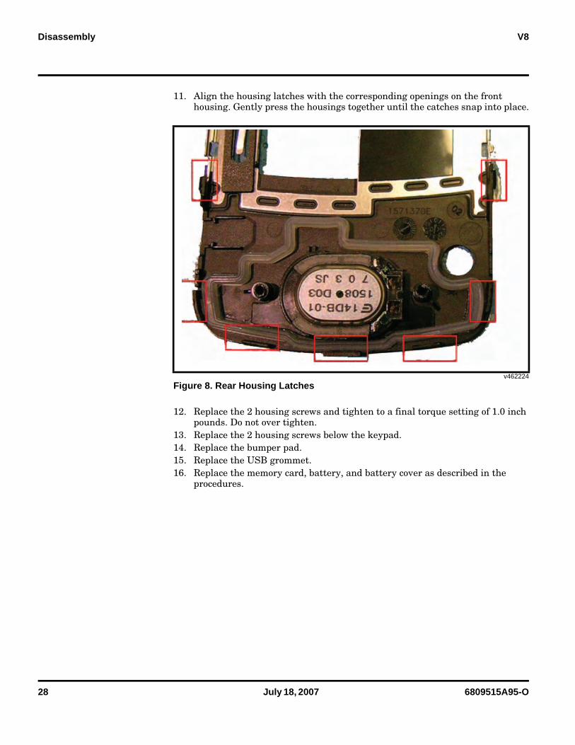
11. Align the housing latches with the corresponding openings on the front housing. Gently press the housings together until the catches snap into place.
12. Replace the 2 housing screws and tighten to a final torque setting of 1.0 inch pounds. Do not over tighten.
13. Replace the 2 housing screws below the keypad.14. Replace the bumper pad.15. Replace the USB grommet.16. Replace the memory card, battery, and battery cover as described in the
procedures.
v462224
Figure 8. Rear Housing Latches
6809515A95-O July 18, 2007 29
Level 1 and 2 Service Manual Disassembly
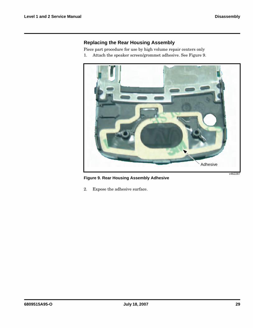
Replacing the Rear Housing Assembly Piece part procedure for use by high volume repair centers only1. Attach the speaker screen/grommet adhesive. See Figure 9.
2. Expose the adhesive surface.
v462287
Figure 9. Rear Housing Assembly Adhesive
Adhesive
30 July 18, 2007 6809515A95-O
Disassembly V8
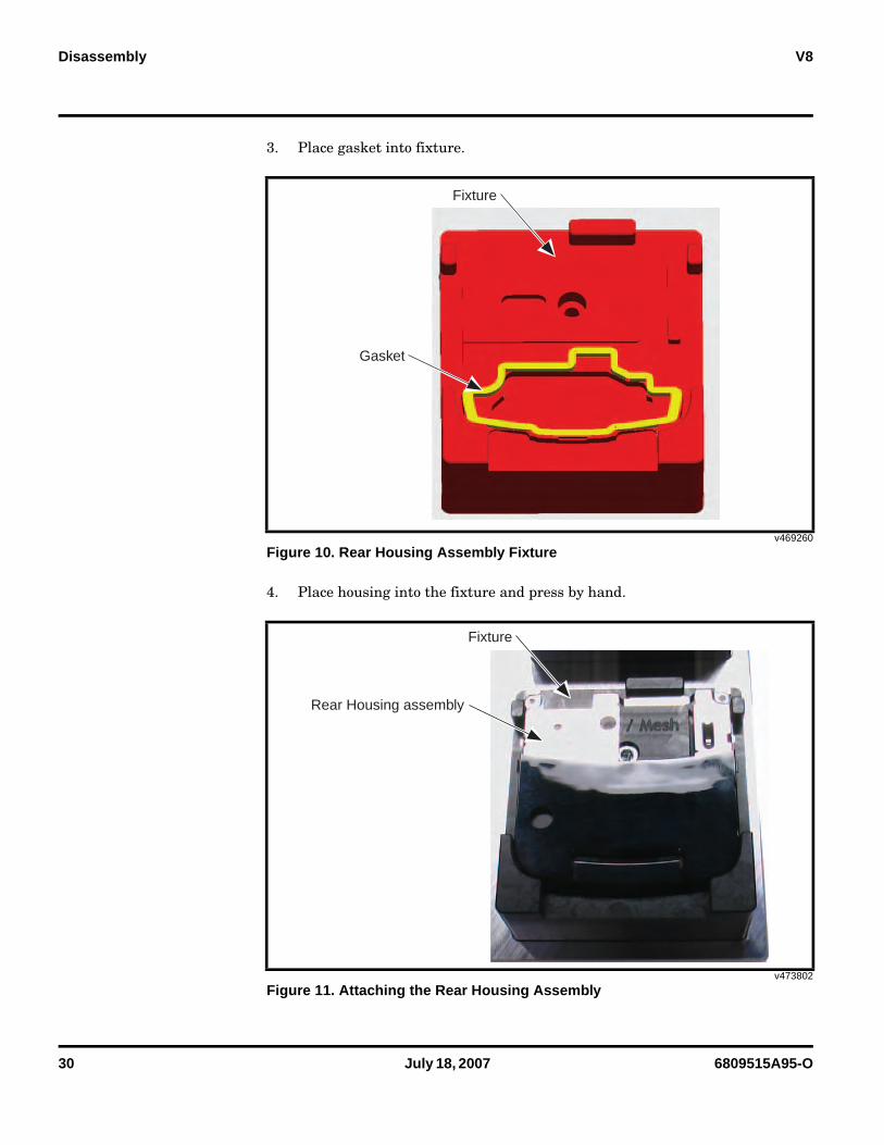
3. Place gasket into fixture.
4. Place housing into the fixture and press by hand.
v469260
Figure 10. Rear Housing Assembly Fixture
v473802
Figure 11. Attaching the Rear Housing Assembly
Fixture
Gasket
Fixture
Rear Housing assembly
6809515A95-O July 18, 2007 31
Level 1 and 2 Service Manual Disassembly
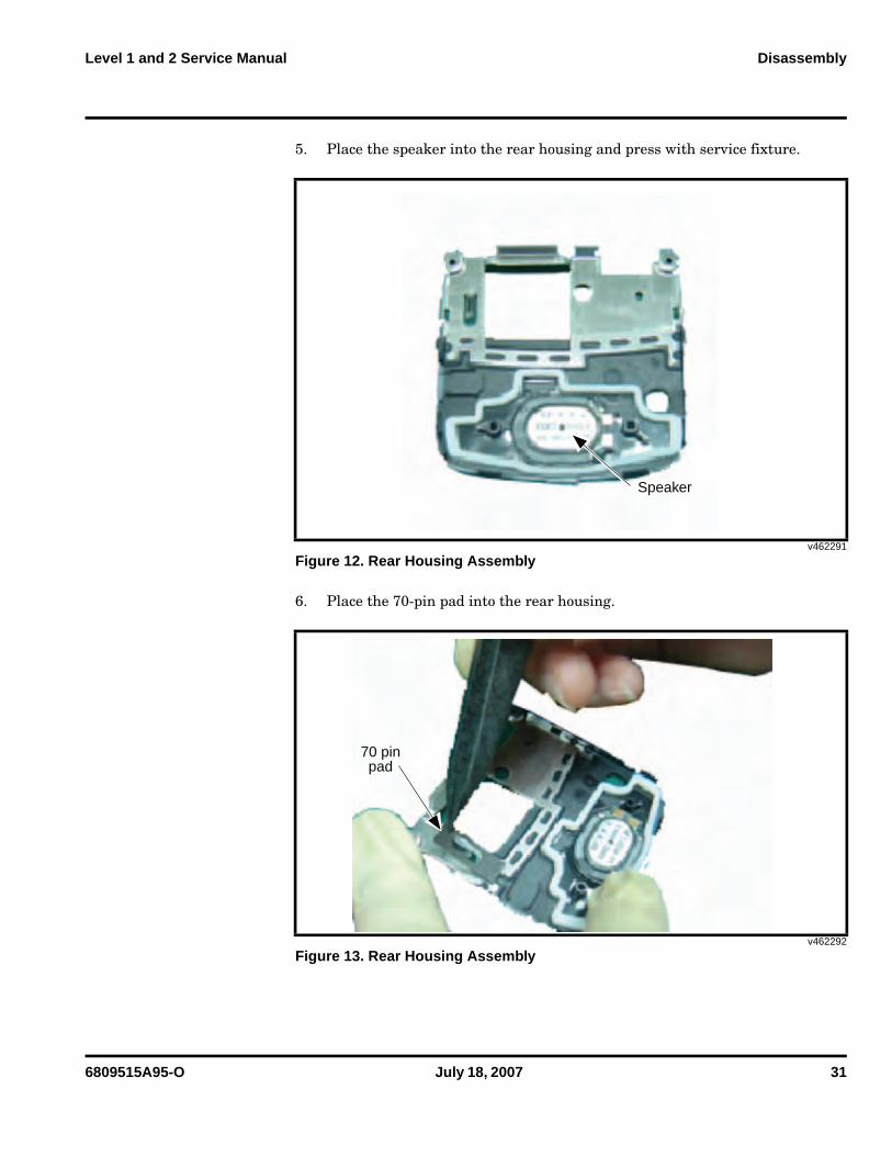
5. Place the speaker into the rear housing and press with service fixture.
6. Place the 70-pin pad into the rear housing.
v462291
Figure 12. Rear Housing Assembly
v462292
Figure 13. Rear Housing Assembly
Speaker
70 pinpad
32 July 18, 2007 6809515A95-O
Disassembly V8
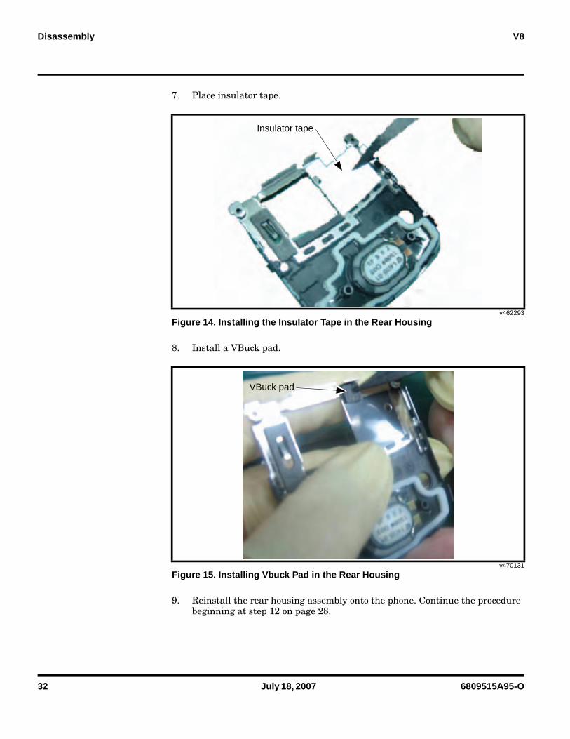
7. Place insulator tape.
8. Install a VBuck pad.
9. Reinstall the rear housing assembly onto the phone. Continue the procedure beginning at step 12 on page 28.
v462293
Figure 14. Installing the Insulator Tape in the Rear Housing
v470131
Figure 15. Installing Vbuck Pad in the Rear Housing
Insulator tape
VBuck pad
6809515A95-O July 18, 2007 33
Level 1 and 2 Service Manual Disassembly
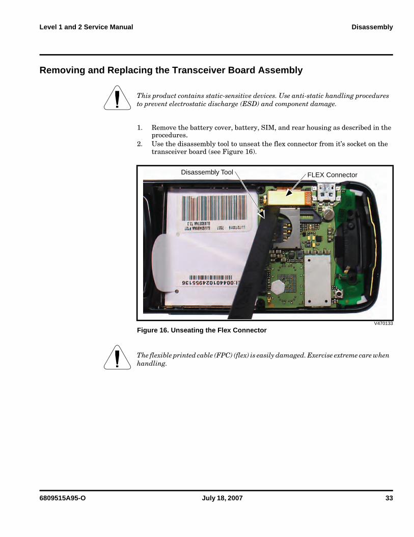
Removing and Replacing the Transceiver Board Assembly
1. Remove the battery cover, battery, SIM, and rear housing as described in the procedures.
2. Use the disassembly tool to unseat the flex connector from it’s socket on the transceiver board (see Figure 16).
G This product contains static-sensitive devices. Use anti-static handling procedures to prevent electrostatic discharge (ESD) and component damage.
V470133
Figure 16. Unseating the Flex Connector
G The flexible printed cable (FPC) (flex) is easily damaged. Exercise extreme care when handling.
Disassembly Tool FLEX Connector
34 July 18, 2007 6809515A95-O
Disassembly V8
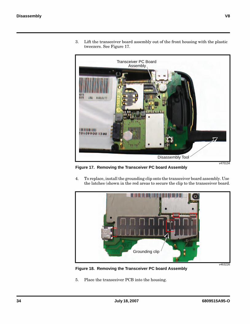
3. Lift the transceiver board assembly out of the front housing with the plastic tweezers. See Figure 17.
4. To replace, install the grounding clip onto the transceiver board assembly. Use the latches (shown in the red areas to secure the clip to the transceiver board.
5. Place the transceiver PCB into the housing.
v470134
Figure 17. Removing the Transceiver PC board Assembly
v463226
Figure 18. Removing the Transceiver PC board Assembly
Transceiver PC Board Assembly
Disassembly Tool
Grounding clip
6809515A95-O July 18, 2007 35
Level 1 and 2 Service Manual Disassembly
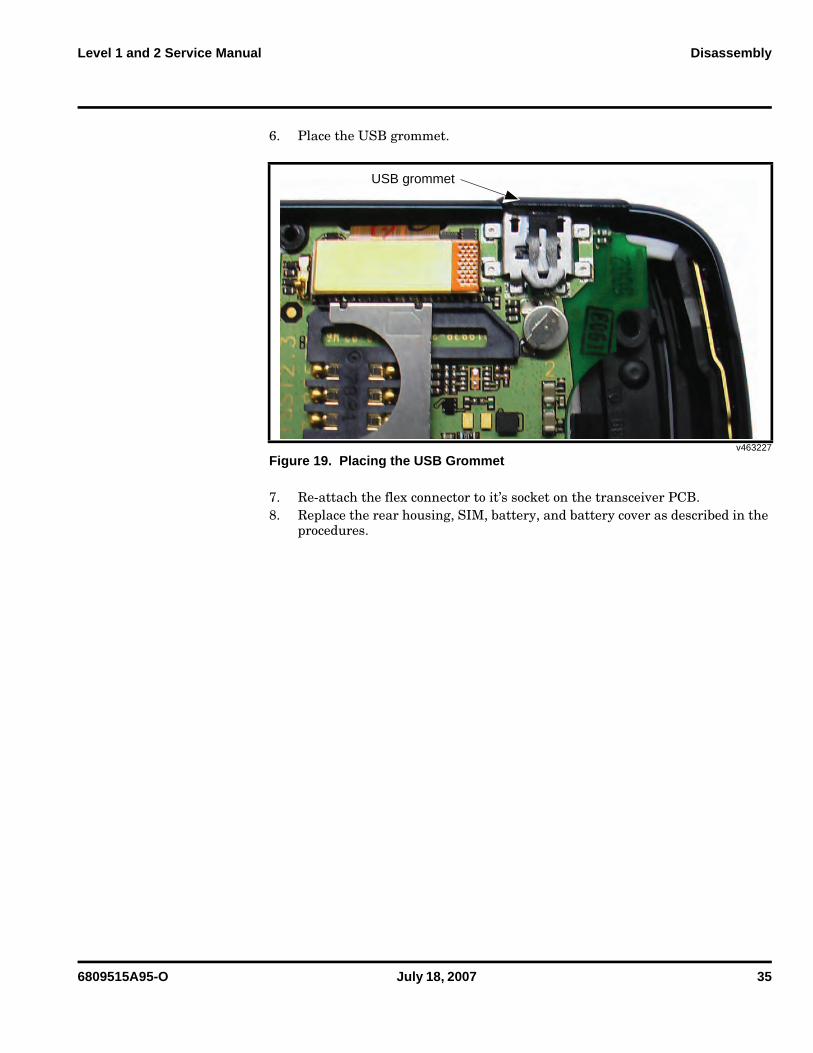
6. Place the USB grommet.
7. Re-attach the flex connector to it’s socket on the transceiver PCB.8. Replace the rear housing, SIM, battery, and battery cover as described in the
procedures.
v463227
Figure 19. Placing the USB Grommet
USB grommet
36 July 18, 2007 6809515A95-O
Disassembly V8
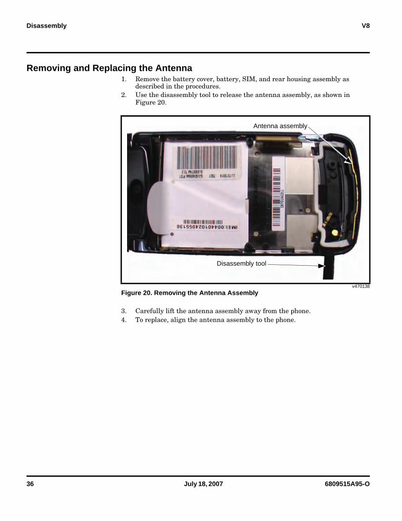
Removing and Replacing the Antenna1. Remove the battery cover, battery, SIM, and rear housing assembly as
described in the procedures.2. Use the disassembly tool to release the antenna assembly, as shown in
Figure 20.
3. Carefully lift the antenna assembly away from the phone.4. To replace, align the antenna assembly to the phone.
v470138
Figure 20. Removing the Antenna Assembly
Disassembly tool
Antenna assembly
6809515A95-O July 18, 2007 37
Level 1 and 2 Service Manual Disassembly
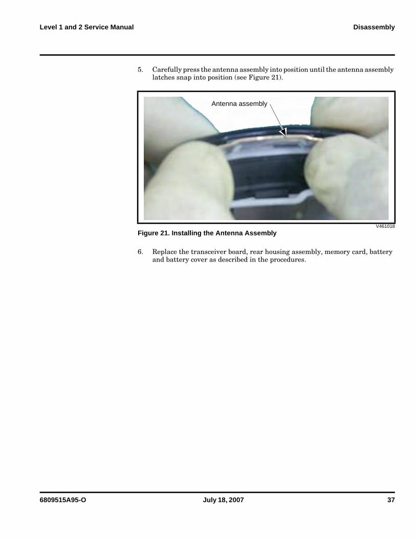
5. Carefully press the antenna assembly into position until the antenna assembly latches snap into position (see Figure 21).
6. Replace the transceiver board, rear housing assembly, memory card, battery and battery cover as described in the procedures.
V461018
Figure 21. Installing the Antenna Assembly
Antenna assembly
38 July 18, 2007 6809515A95-O
Disassembly V8
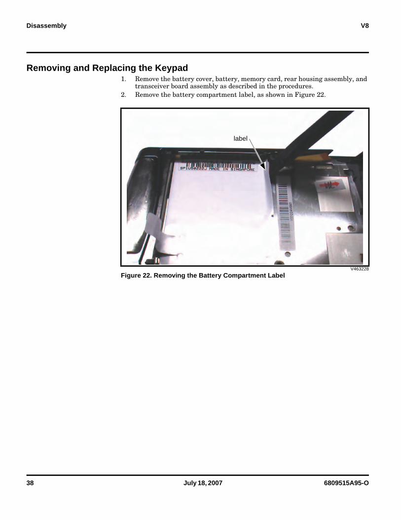
Removing and Replacing the Keypad1. Remove the battery cover, battery, memory card, rear housing assembly, and
transceiver board assembly as described in the procedures.2. Remove the battery compartment label, as shown in Figure 22.
V463228
Figure 22. Removing the Battery Compartment Label
label
6809515A95-O July 18, 2007 39
Level 1 and 2 Service Manual Disassembly
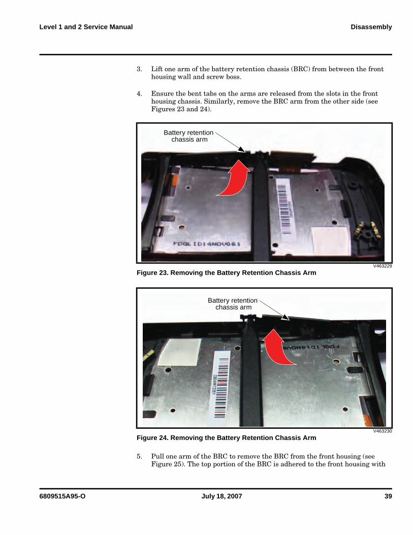
3. Lift one arm of the battery retention chassis (BRC) from between the front housing wall and screw boss.
4. Ensure the bent tabs on the arms are released from the slots in the front housing chassis. Similarly, remove the BRC arm from the other side (see Figures 23 and 24).
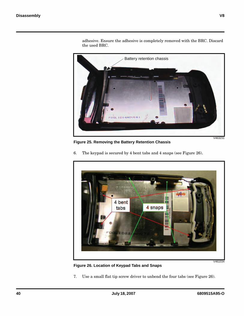
5. Pull one arm of the BRC to remove the BRC from the front housing (see Figure 25). The top portion of the BRC is adhered to the front housing with
V463229
Figure 23. Removing the Battery Retention Chassis Arm
V463230
Figure 24. Removing the Battery Retention Chassis Arm
Battery retention chassis arm
Battery retention chassis arm
40 July 18, 2007 6809515A95-O
Disassembly V8
adhesive. Ensure the adhesive is completely removed with the BRC. Discard the used BRC.
6. The keypad is secured by 4 bent tabs and 4 snaps (see Figure 26).
7. Use a small flat tip screw driver to unbend the four tabs (see Figure 26).
V463231
Figure 25. Removing the Battery Retention Chassis
V461034
Figure 26. Location of Keypad Tabs and Snaps
Battery retention chassis
6809515A95-O July 18, 2007 41
Level 1 and 2 Service Manual Disassembly
8. Use a small flat tip screw driver to release the four side snaps. When the snap releases, press down slightly on the tab to push the keypad away from the front housing to prevent the snap from re-engaging. Extra caution should be taken when releasing the snap behind the keypad flex connector - DO NOT DAMAGE THE FLEX.
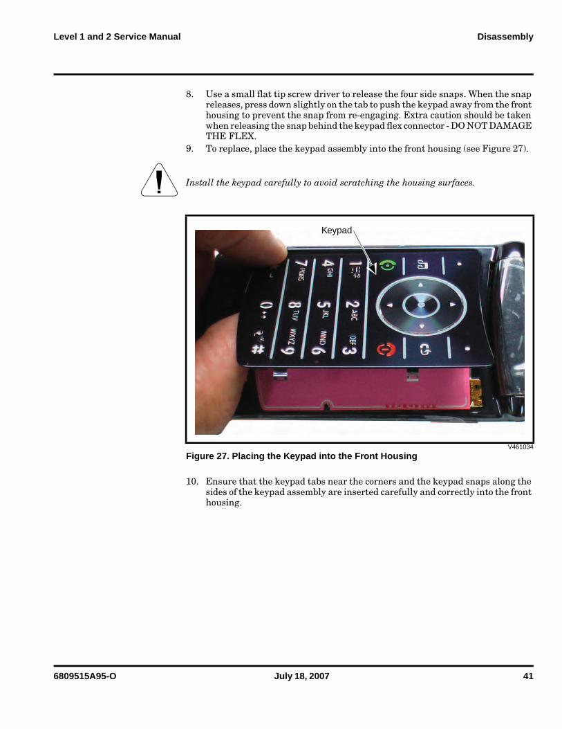
9. To replace, place the keypad assembly into the front housing (see Figure 27).
10. Ensure that the keypad tabs near the corners and the keypad snaps along the sides of the keypad assembly are inserted carefully and correctly into the front housing.
G Install the keypad carefully to avoid scratching the housing surfaces.
V461034
Figure 27. Placing the Keypad into the Front Housing
Keypad
42 July 18, 2007 6809515A95-O
Disassembly V8
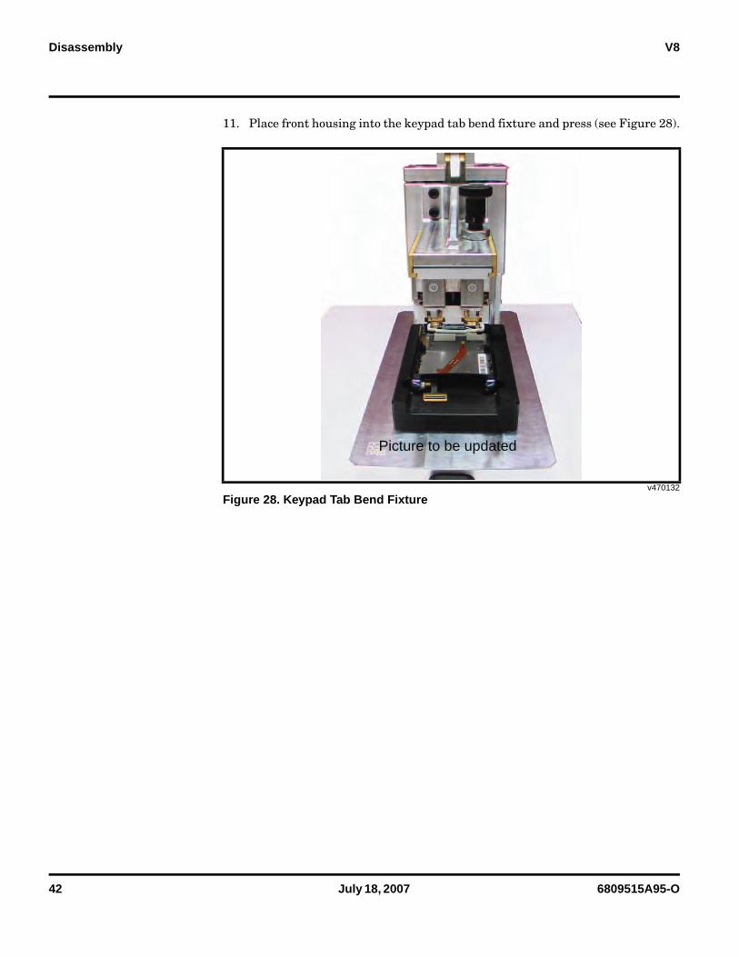
11. Place front housing into the keypad tab bend fixture and press (see Figure 28).
v470132
Figure 28. Keypad Tab Bend Fixture
Picture to be updated
6809515A95-O July 18, 2007 43
Level 1 and 2 Service Manual Disassembly
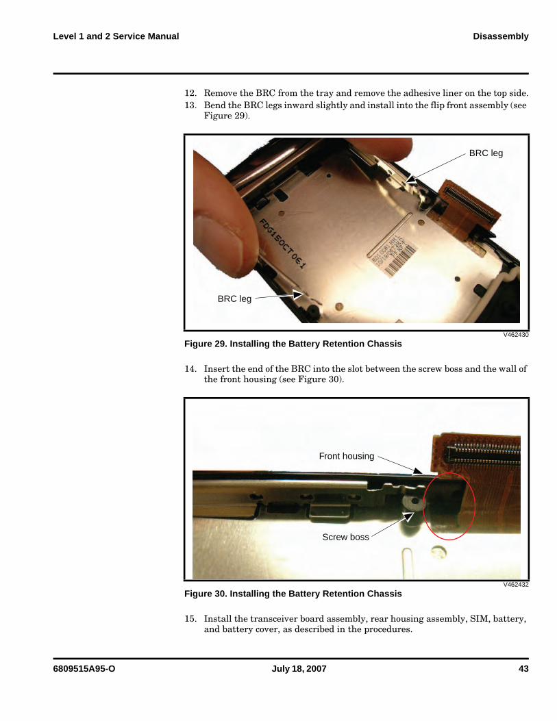
12. Remove the BRC from the tray and remove the adhesive liner on the top side.13. Bend the BRC legs inward slightly and install into the flip front assembly (see
Figure 29).
14. Insert the end of the BRC into the slot between the screw boss and the wall of the front housing (see Figure 30).
15. Install the transceiver board assembly, rear housing assembly, SIM, battery, and battery cover, as described in the procedures.
V462430
Figure 29. Installing the Battery Retention Chassis
V462432
Figure 30. Installing the Battery Retention Chassis
BRC leg
BRC leg
Front housing
Screw boss
44 July 18, 2007 6809515A95-O
Disassembly V8
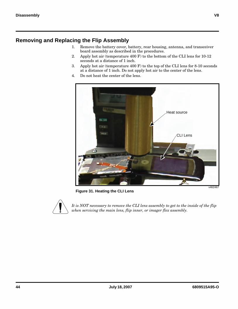
Removing and Replacing the Flip Assembly1. Remove the battery cover, battery, rear housing, antenna, and transceiver
board assembly as described in the procedures.2. Apply hot air (temperature 400 F) to the bottom of the CLI lens for 10-12
seconds at a distance of 1 inch. 3. Apply hot air (temperature 400 F) to the top of the CLI lens for 8-10 seconds
at a distance of 1 inch. Do not apply hot air to the center of the lens.4. Do not heat the center of the lens.
v462467
Figure 31. Heating the CLI Lens
G It is NOT necessary to remove the CLI lens assembly to get to the inside of the flip when servicing the main lens, flip inner, or imager flex assembly.
Heat source
CLI Lens
6809515A95-O July 18, 2007 45
Level 1 and 2 Service Manual Disassembly
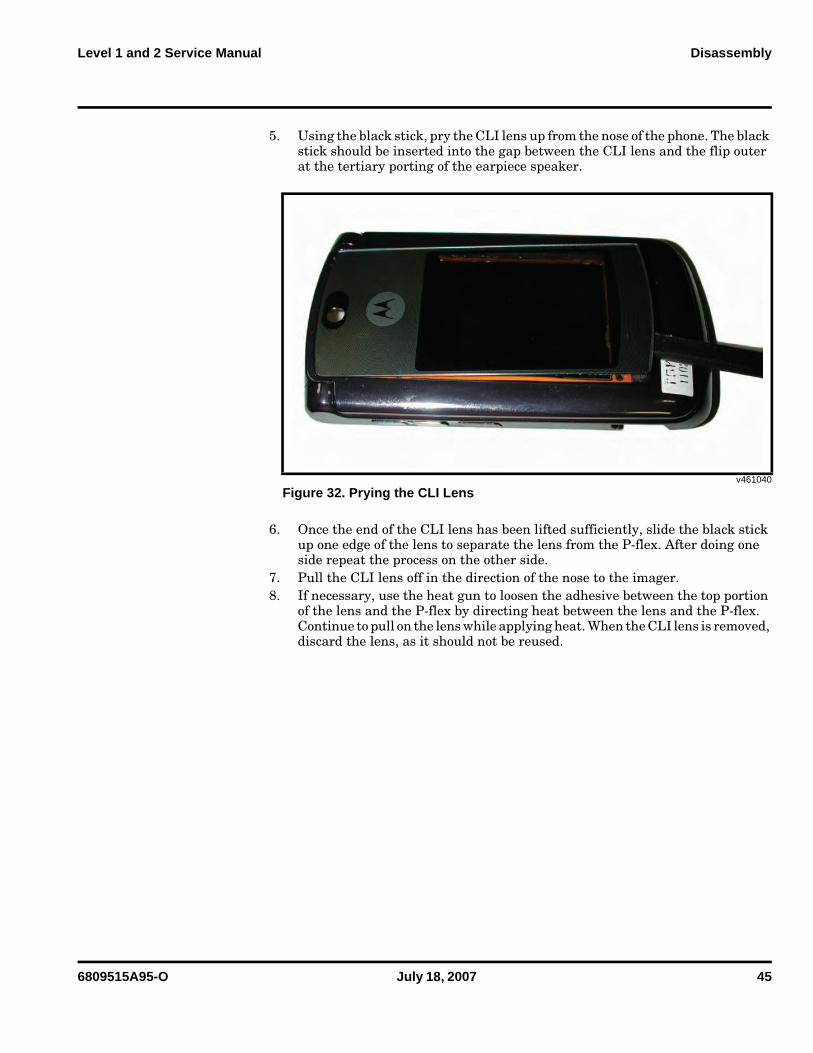
5. Using the black stick, pry the CLI lens up from the nose of the phone. The black stick should be inserted into the gap between the CLI lens and the flip outer at the tertiary porting of the earpiece speaker.
6. Once the end of the CLI lens has been lifted sufficiently, slide the black stick up one edge of the lens to separate the lens from the P-flex. After doing one side repeat the process on the other side.
7. Pull the CLI lens off in the direction of the nose to the imager.8. If necessary, use the heat gun to loosen the adhesive between the top portion
of the lens and the P-flex by directing heat between the lens and the P-flex. Continue to pull on the lens while applying heat. When the CLI lens is removed, discard the lens, as it should not be reused.
v461040
Figure 32. Prying the CLI Lens
46 July 18, 2007 6809515A95-O
Disassembly V8
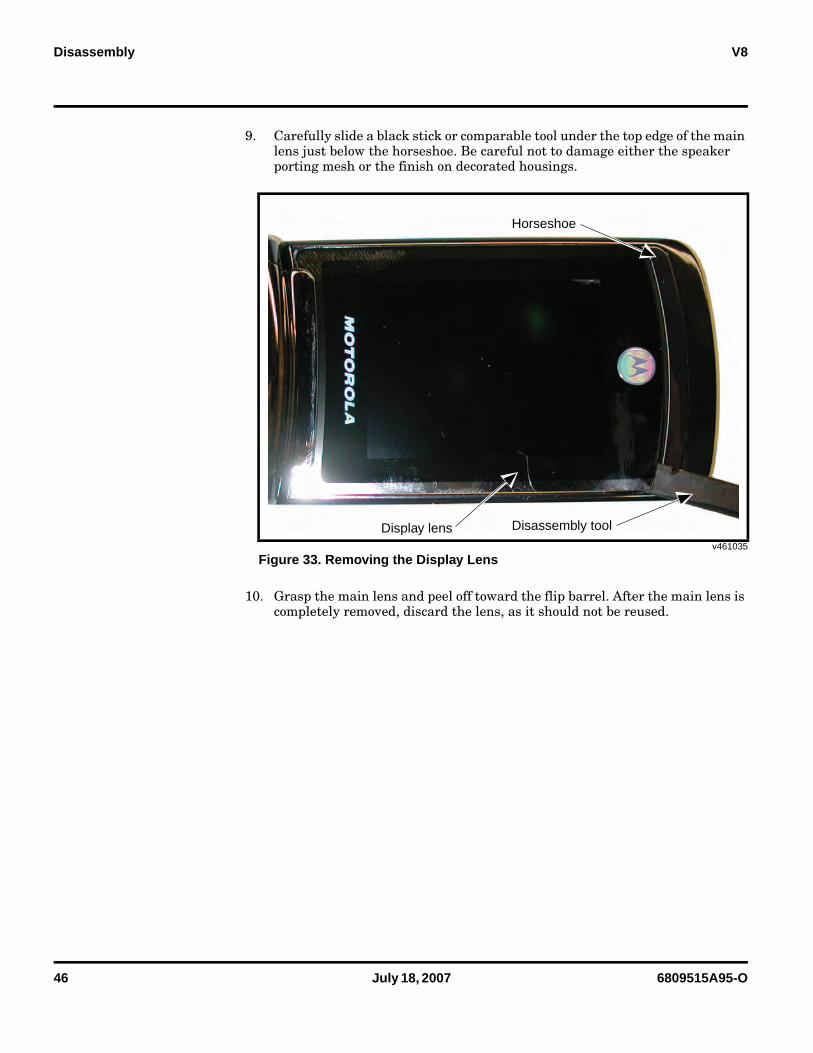
9. Carefully slide a black stick or comparable tool under the top edge of the main lens just below the horseshoe. Be careful not to damage either the speaker porting mesh or the finish on decorated housings.
10. Grasp the main lens and peel off toward the flip barrel. After the main lens is completely removed, discard the lens, as it should not be reused.
v461035
Figure 33. Removing the Display Lens
Display lens Disassembly tool
Horseshoe
6809515A95-O July 18, 2007 47
Level 1 and 2 Service Manual Disassembly
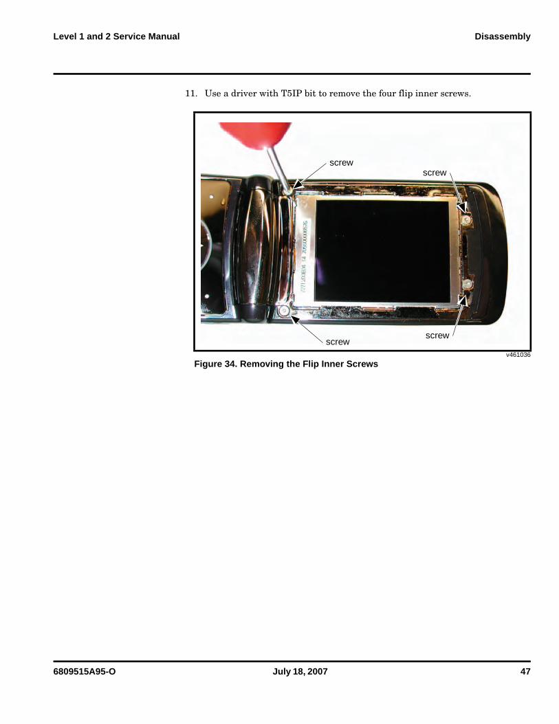
11. Use a driver with T5IP bit to remove the four flip inner screws.
v461036
Figure 34. Removing the Flip Inner Screws
screw
screwscrew
screw
48 July 18, 2007 6809515A95-O
Disassembly V8
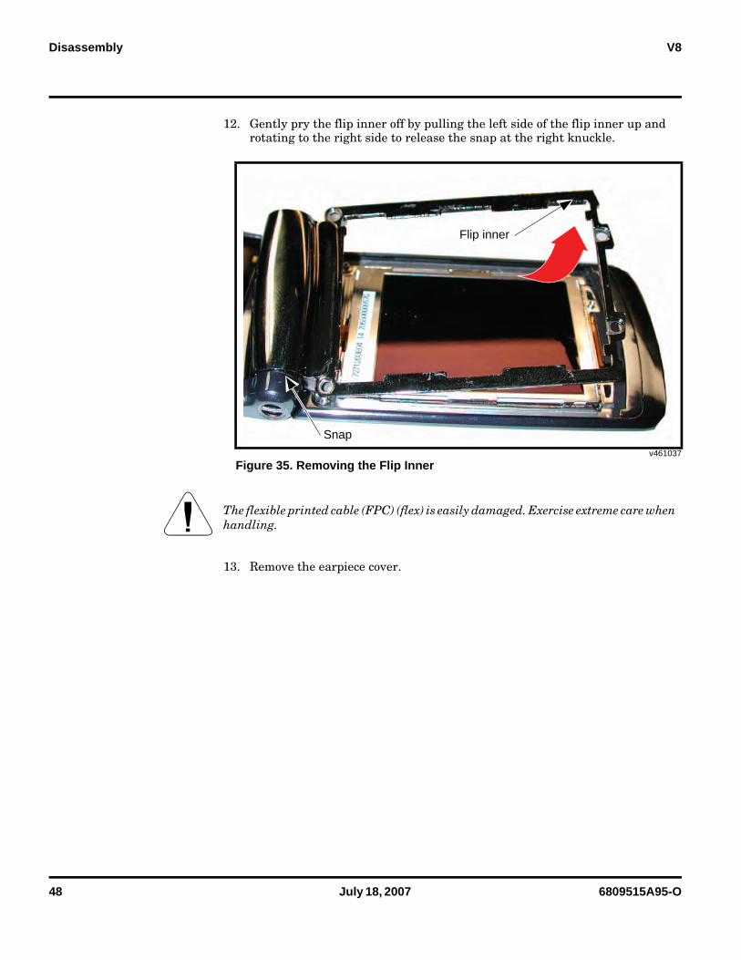
12. Gently pry the flip inner off by pulling the left side of the flip inner up and rotating to the right side to release the snap at the right knuckle.
13. Remove the earpiece cover.
v461037
Figure 35. Removing the Flip Inner
G The flexible printed cable (FPC) (flex) is easily damaged. Exercise extreme care when handling.
Flip inner
Snap
6809515A95-O July 18, 2007 49
Level 1 and 2 Service Manual Disassembly
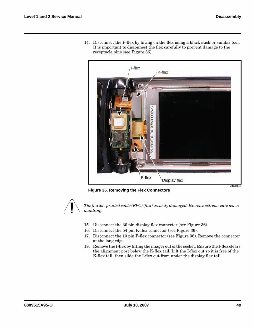
14. Disconnect the P-flex by lifting on the flex using a black stick or similar tool. It is important to disconnect the flex carefully to prevent damage to the receptacle pins (see Figure 36).
15. Disconnect the 30 pin display flex connector (see Figure 36).16. Disconnect the 54 pin K-flex connector (see Figure 36).17. Disconnect the 10 pin P-flex connector (see Figure 36). Remove the connector
at the long edge.18. Remove the I-flex by lifting the imager out of the socket. Ensure the I-flex clears
the alignment post below the K-flex tail. Lift the I-flex out so it is free of the K-flex tail, then slide the I-flex out from under the display flex tail.
v461038
Figure 36. Removing the Flex Connectors
G The flexible printed cable (FPC) (flex) is easily damaged. Exercise extreme care when handling.
P-flex
K-flex
Display flex
I-flex
50 July 18, 2007 6809515A95-O
Disassembly V8
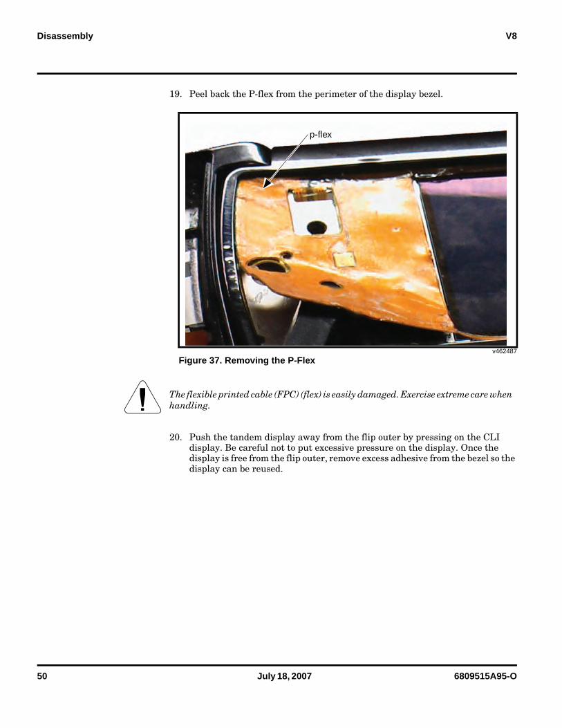
19. Peel back the P-flex from the perimeter of the display bezel.
20. Push the tandem display away from the flip outer by pressing on the CLI display. Be careful not to put excessive pressure on the display. Once the display is free from the flip outer, remove excess adhesive from the bezel so the display can be reused.
v462487
Figure 37. Removing the P-Flex
G The flexible printed cable (FPC) (flex) is easily damaged. Exercise extreme care when handling.
p-flex
6809515A95-O July 18, 2007 51
Level 1 and 2 Service Manual Disassembly
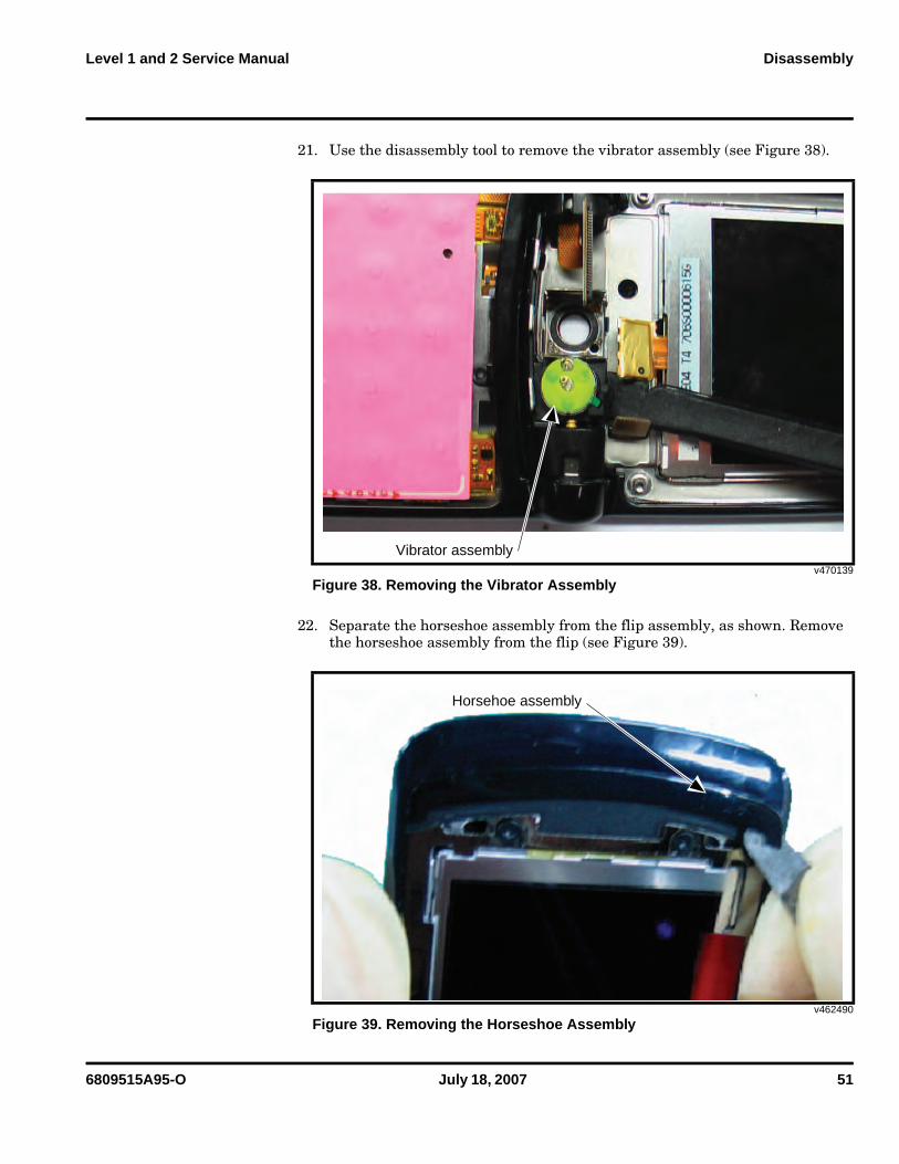
21. Use the disassembly tool to remove the vibrator assembly (see Figure 38).
22. Separate the horseshoe assembly from the flip assembly, as shown. Remove the horseshoe assembly from the flip (see Figure 39).
v470139
Figure 38. Removing the Vibrator Assembly
v462490
Figure 39. Removing the Horseshoe Assembly
Vibrator assembly
Horsehoe assembly
52 July 18, 2007 6809515A95-O
Disassembly V8
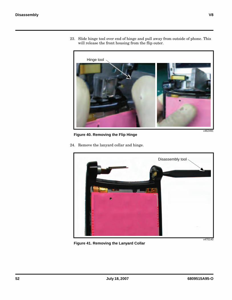
23. Slide hinge tool over end of hinge and pull away from outside of phone. This will release the front housing from the flip outer.
24. Remove the lanyard collar and hinge.
v462491
Figure 40. Removing the Flip Hinge
v470140
Figure 41. Removing the Lanyard Collar
Hinge tool
Disassembly tool
6809515A95-O July 18, 2007 53
Level 1 and 2 Service Manual Disassembly
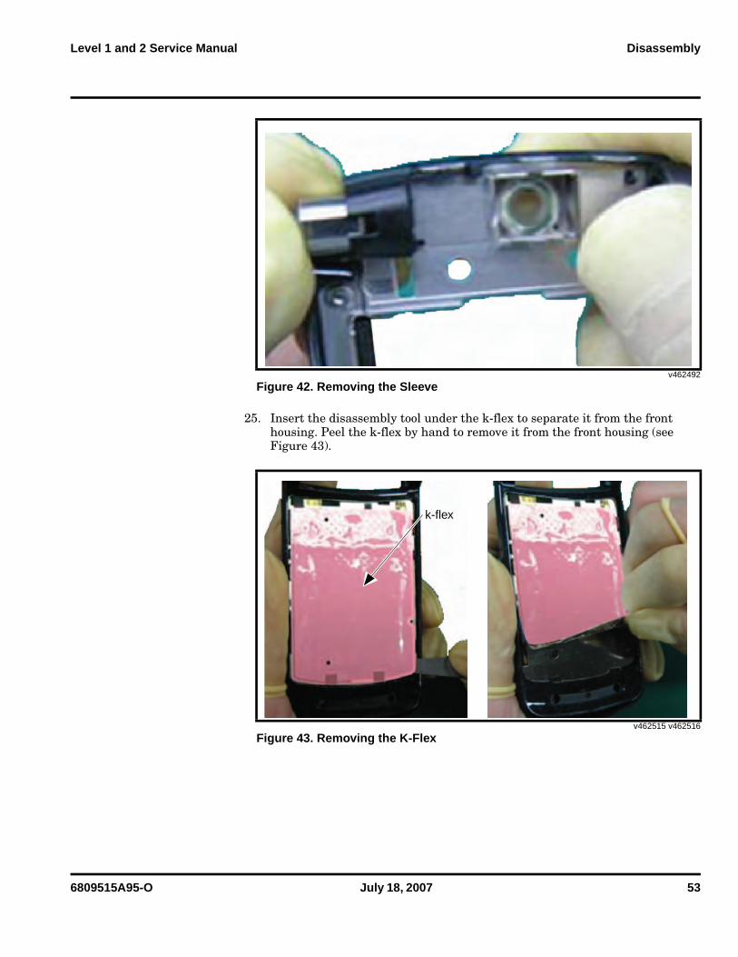
25. Insert the disassembly tool under the k-flex to separate it from the front housing. Peel the k-flex by hand to remove it from the front housing (see Figure 43).
v462492
Figure 42. Removing the Sleeve
v462515 v462516
Figure 43. Removing the K-Flex
k-flex
54 July 18, 2007 6809515A95-O
Disassembly V8
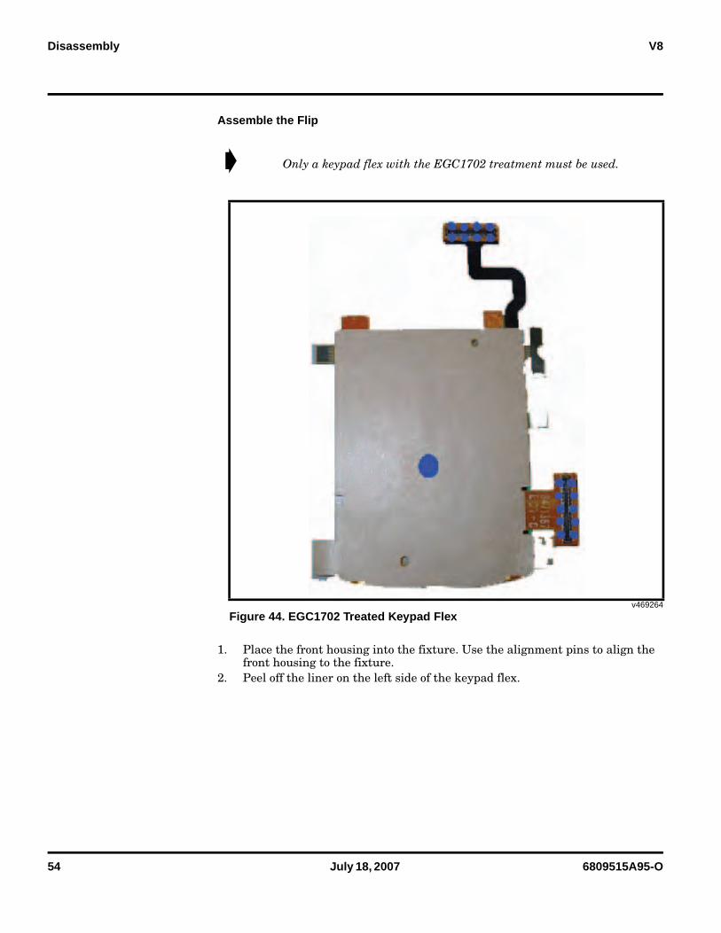
Assemble the Flip
1. Place the front housing into the fixture. Use the alignment pins to align the front housing to the fixture.
2. Peel off the liner on the left side of the keypad flex.
➧ Only a keypad flex with the EGC1702 treatment must be used.
v469264
Figure 44. EGC1702 Treated Keypad Flex
6809515A95-O July 18, 2007 55
Level 1 and 2 Service Manual Disassembly
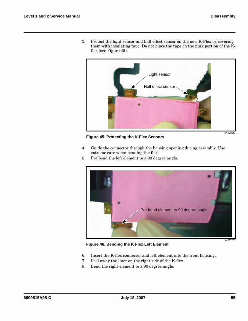
3. Protect the light sensor and hall effect sensor on the new K-Flex by covering them with insulating tape. Do not place the tape on the pink portion of the K-flex (see Figure 45).
4. Guide the connector through the housing opening during assembly. Use extreme care when bending the flex.
5. Pre bend the left element to a 90 degree angle.
6. Insert the K-flex connector and left element into the front housing.7. Peel away the liner on the right side of the K-flex.8. Bend the right element to a 90 degree angle.
v462522
Figure 45. Protecting the K-Flex Sensors
v462528
Figure 46. Bending the K Flex Left Element
Light sensor
Hall effect sensor
Pre bend element to 90 degree angle
56 July 18, 2007 6809515A95-O
Disassembly V8
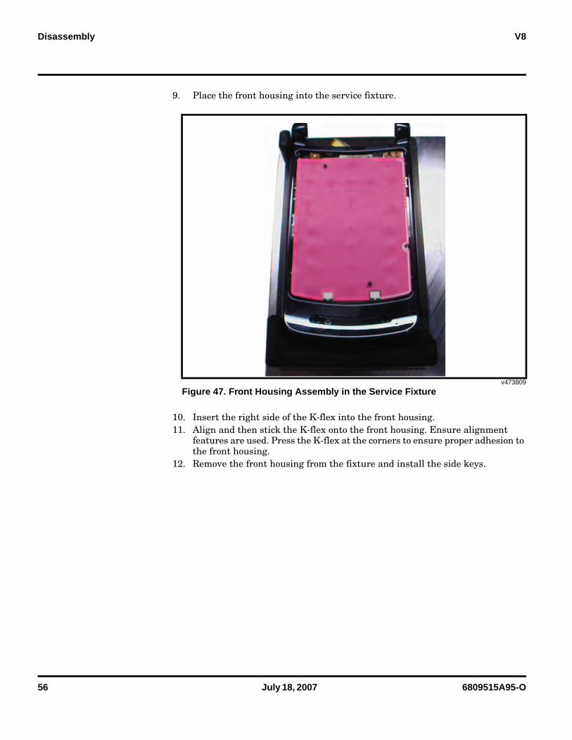
9. Place the front housing into the service fixture.
10. Insert the right side of the K-flex into the front housing.11. Align and then stick the K-flex onto the front housing. Ensure alignment
features are used. Press the K-flex at the corners to ensure proper adhesion to the front housing.
12. Remove the front housing from the fixture and install the side keys.
v473809
Figure 47. Front Housing Assembly in the Service Fixture
6809515A95-O July 18, 2007 57
Level 1 and 2 Service Manual Disassembly
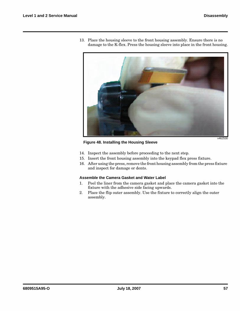
13. Place the housing sleeve to the front housing assembly. Ensure there is no damage to the K-flex. Press the housing sleeve into place in the front housing.
14. Inspect the assembly before proceeding to the next step.15. Insert the front housing assembly into the keypad flex press fixture.16. After using the press, remove the front housing assembly from the press fixture
and inspect for damage or dents.
Assemble the Camera Gasket and Water Label1. Peel the liner from the camera gasket and place the camera gasket into the
fixture with the adhesive side facing upwards.2. Place the flip outer assembly. Use the fixture to correctly align the outer
assembly.
v462530
Figure 48. Installing the Housing Sleeve
58 July 18, 2007 6809515A95-O
Disassembly V8
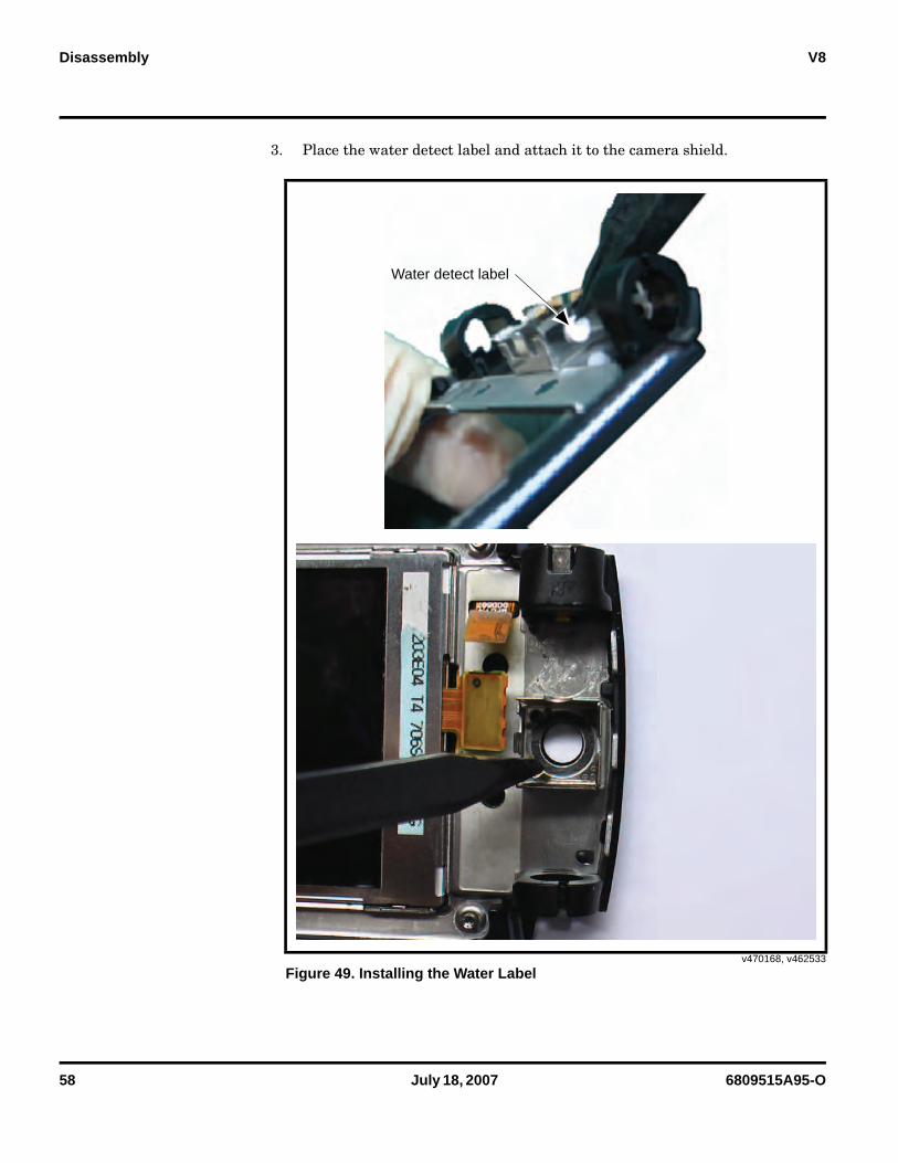
3. Place the water detect label and attach it to the camera shield.
v470168, v462533
Figure 49. Installing the Water Label
Water detect label
6809515A95-O July 18, 2007 59
Level 1 and 2 Service Manual Disassembly
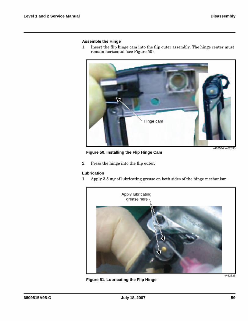
Assemble the Hinge1. Insert the flip hinge cam into the flip outer assembly. The hinge center must
remain horizontal (see Figure 50).
2. Press the hinge into the flip outer.
Lubrication1. Apply 3.5 mg of lubricating grease on both sides of the hinge mechanism.
v462534 v462535
Figure 50. Installing the Flip Hinge Cam
v462536
Figure 51. Lubricating the Flip Hinge
Hinge cam
Apply lubricating grease here
60 July 18, 2007 6809515A95-O
Disassembly V8
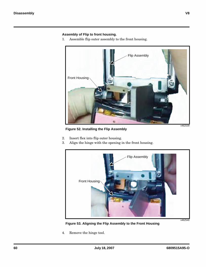
Assembly of Flip to front housing.1. Assemble flip outer assembly to the front housing.
2. Insert flex into flip outer housing.3. Align the hinge with the opening in the front housing.
4. Remove the hinge tool.
v462539
Figure 52. Installing the Flip Assembly
v462540
Figure 53. Aligning the Flip Assembly to the Front Housing
Flip Assembly
Front Housing
Flip Assembly
Front Housing
6809515A95-O July 18, 2007 61
Level 1 and 2 Service Manual Disassembly
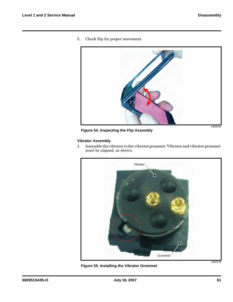
5. Check flip for proper movement.
Vibrator Assembly1. Assemble the vibrator to the vibrator grommet. Vibrator and vibrator grommet
must be aligned, as shown.
v462541
Figure 54. Inspecting the Flip Assembly
v462578
Figure 55. Installing the Vibrator Grommet
Grommet
Vibrator
62 July 18, 2007 6809515A95-O
Disassembly V8
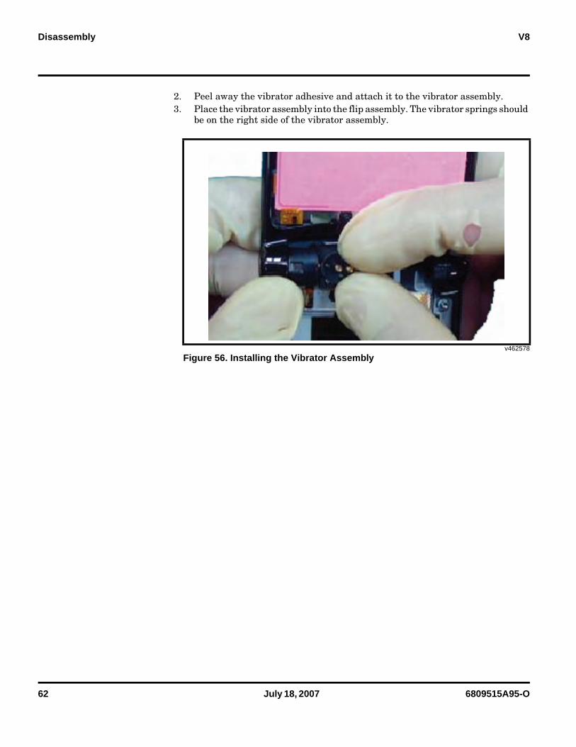
2. Peel away the vibrator adhesive and attach it to the vibrator assembly.3. Place the vibrator assembly into the flip assembly. The vibrator springs should
be on the right side of the vibrator assembly.
v462578
Figure 56. Installing the Vibrator Assembly
6809515A95-O July 18, 2007 63
Level 1 and 2 Service Manual Disassembly
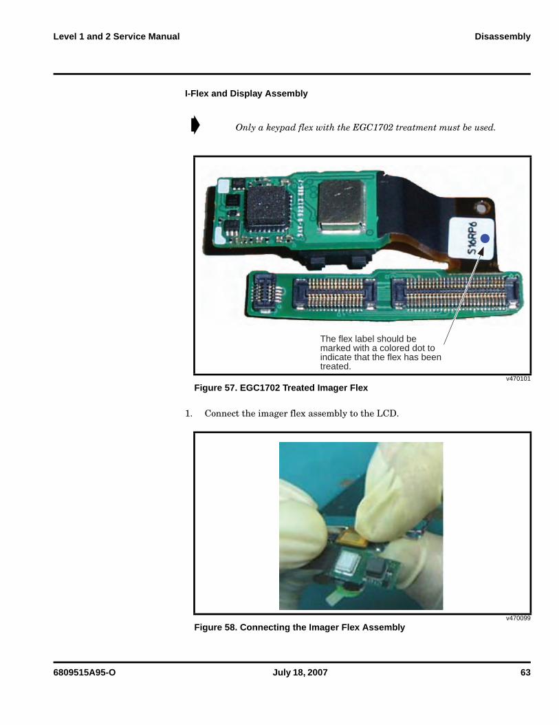
I-Flex and Display Assembly
1. Connect the imager flex assembly to the LCD.
➧ Only a keypad flex with the EGC1702 treatment must be used.
v470101
Figure 57. EGC1702 Treated Imager Flex
v470099
Figure 58. Connecting the Imager Flex Assembly
The flex label should be marked with a colored dot to indicate that the flex has beentreated.
64 July 18, 2007 6809515A95-O
Disassembly V8
2. Peel away the liner from the camera, camera gasket and the LCD.3. Place the LCD assembly into the flip assembly.4. Connect the k flex connector.5. Clean dust and foreign matter from the LCD and display lens with an ionized
air gun.
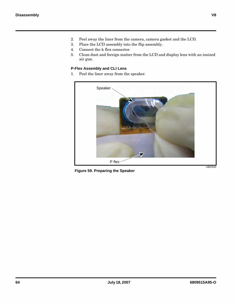
P-Flex Assembly and CLI Lens1. Peel the liner away from the speaker.
v462543
Figure 59. Preparing the Speaker
Speaker
P flex
6809515A95-O July 18, 2007 65
Level 1 and 2 Service Manual Disassembly
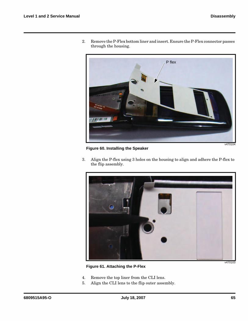
2. Remove the P-Flex bottom liner and insert. Ensure the P-Flex connector passes through the housing.
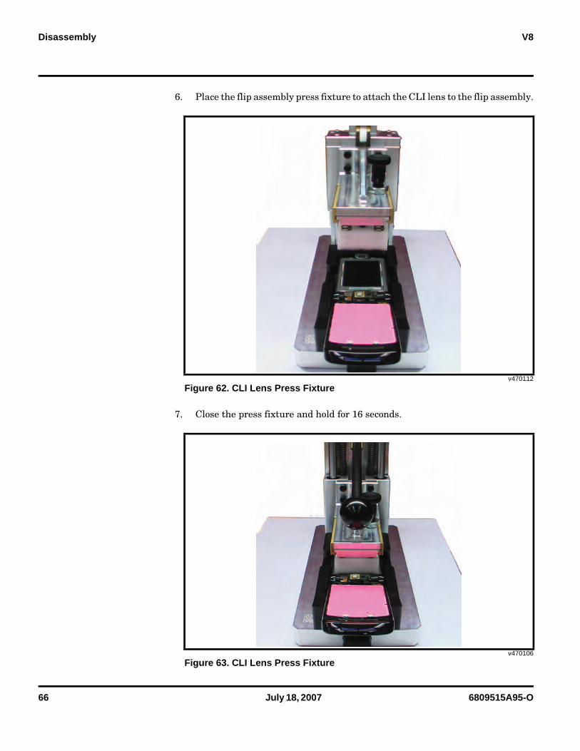
3. Align the P-flex using 3 holes on the housing to align and adhere the P-flex to the flip assembly.
4. Remove the top liner from the CLI lens.5. Align the CLI lens to the flip outer assembly.
v470104
Figure 60. Installing the Speaker
v470103
Figure 61. Attaching the P-Flex
P flex
66 July 18, 2007 6809515A95-O
Disassembly V8
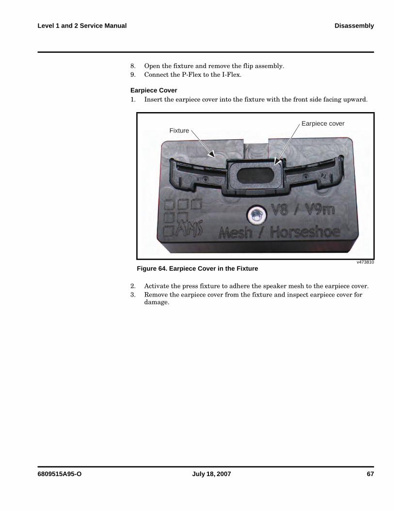
6. Place the flip assembly press fixture to attach the CLI lens to the flip assembly.
7. Close the press fixture and hold for 16 seconds.
v470112
Figure 62. CLI Lens Press Fixture
v470106
Figure 63. CLI Lens Press Fixture
6809515A95-O July 18, 2007 67
Level 1 and 2 Service Manual Disassembly
8. Open the fixture and remove the flip assembly.9. Connect the P-Flex to the I-Flex.
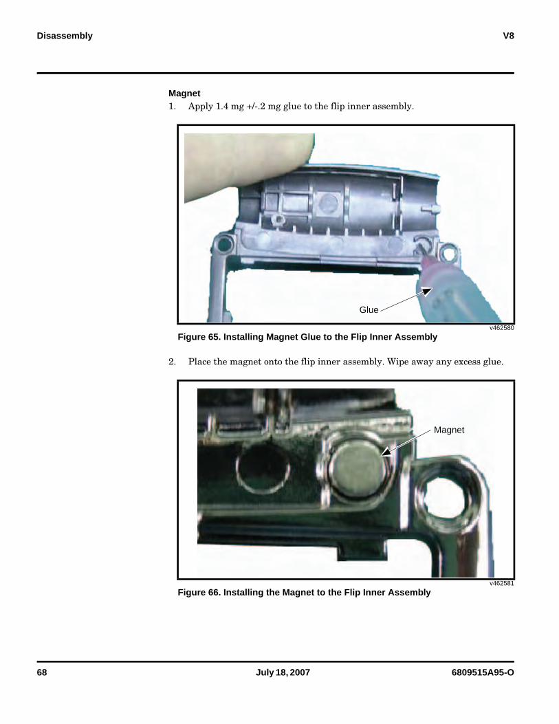
Earpiece Cover1. Insert the earpiece cover into the fixture with the front side facing upward.
2. Activate the press fixture to adhere the speaker mesh to the earpiece cover.3. Remove the earpiece cover from the fixture and inspect earpiece cover for
damage.
v473810
Figure 64. Earpiece Cover in the Fixture
FixtureEarpiece cover
68 July 18, 2007 6809515A95-O
Disassembly V8
Magnet1. Apply 1.4 mg +/-.2 mg glue to the flip inner assembly.
2. Place the magnet onto the flip inner assembly. Wipe away any excess glue.
v462580
Figure 65. Installing Magnet Glue to the Flip Inner Assembly
v462581
Figure 66. Installing the Magnet to the Flip Inner Assembly
Glue
Magnet
6809515A95-O July 18, 2007 69
Level 1 and 2 Service Manual Disassembly
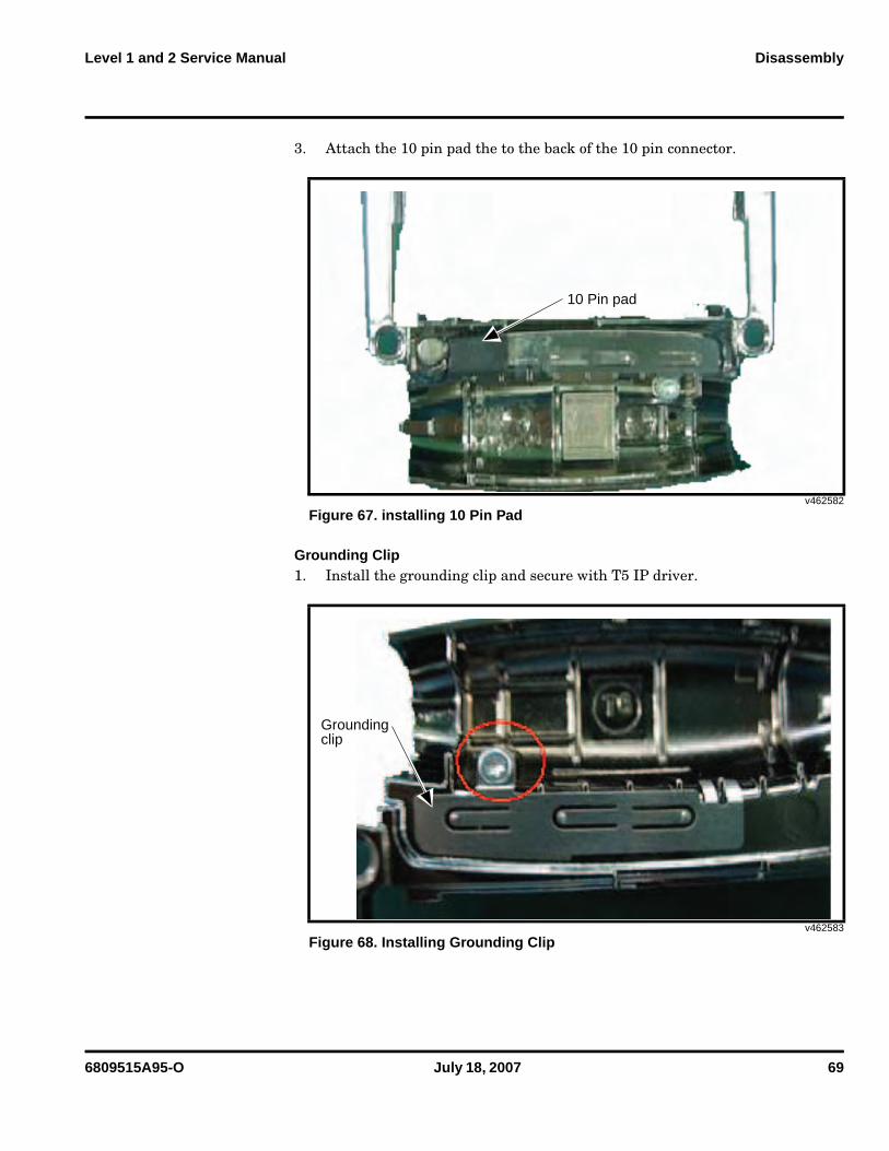
3. Attach the 10 pin pad the to the back of the 10 pin connector.
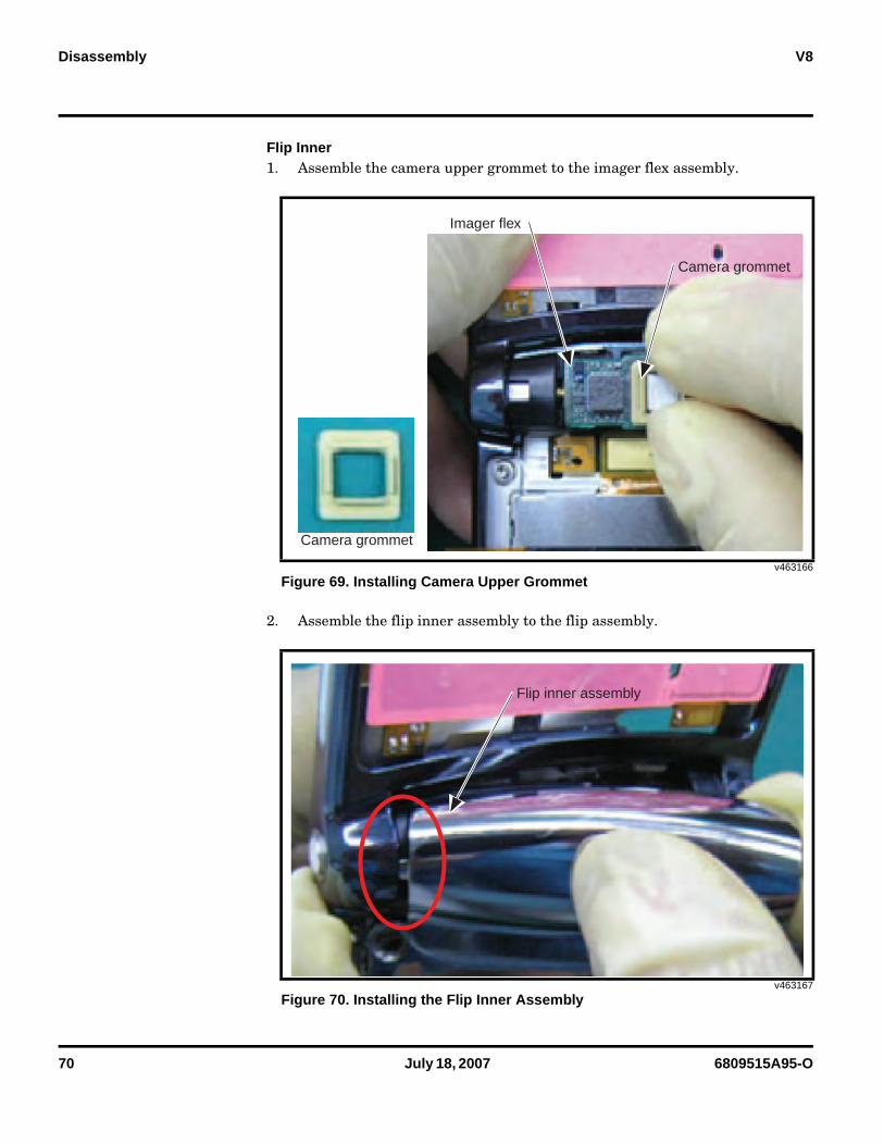
Grounding Clip1. Install the grounding clip and secure with T5 IP driver.
v462582
Figure 67. installing 10 Pin Pad
v462583
Figure 68. Installing Grounding Clip
10 Pin pad
Groundingclip
70 July 18, 2007 6809515A95-O
Disassembly V8
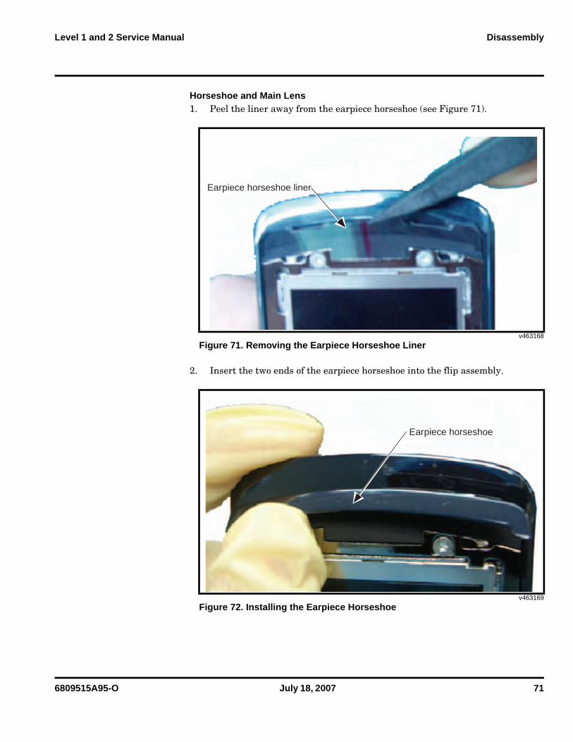
Flip Inner1. Assemble the camera upper grommet to the imager flex assembly.
2. Assemble the flip inner assembly to the flip assembly.
v463166
Figure 69. Installing Camera Upper Grommet
v463167
Figure 70. Installing the Flip Inner Assembly
Camera grommet
Camera grommet
Imager flex
Flip inner assembly
6809515A95-O July 18, 2007 71
Level 1 and 2 Service Manual Disassembly
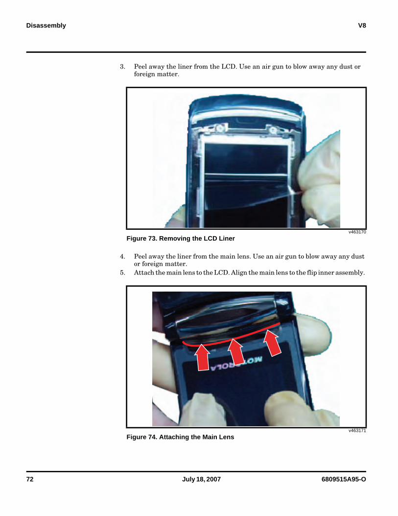
Horseshoe and Main Lens 1. Peel the liner away from the earpiece horseshoe (see Figure 71).
2. Insert the two ends of the earpiece horseshoe into the flip assembly.
v463168
Figure 71. Removing the Earpiece Horseshoe Liner
v463169
Figure 72. Installing the Earpiece Horseshoe
Earpiece horseshoe liner
Earpiece horseshoe
72 July 18, 2007 6809515A95-O
Disassembly V8
3. Peel away the liner from the LCD. Use an air gun to blow away any dust or foreign matter.
4. Peel away the liner from the main lens. Use an air gun to blow away any dust or foreign matter.
5. Attach the main lens to the LCD. Align the main lens to the flip inner assembly.
v463170
Figure 73. Removing the LCD Liner
v463171
Figure 74. Attaching the Main Lens
6809515A95-O July 18, 2007 73
Level 1 and 2 Service Manual Disassembly
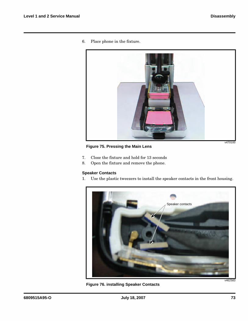
6. Place phone in the fixture.
7. Close the fixture and hold for 13 seconds8. Open the fixture and remove the phone.
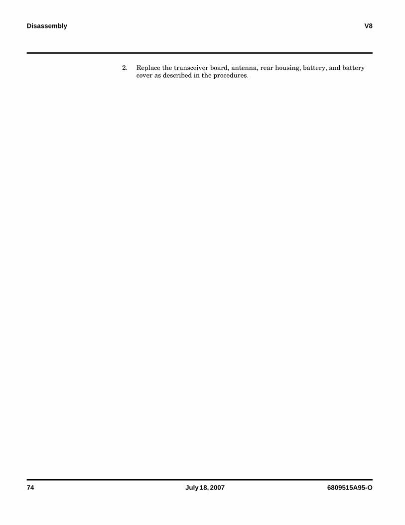
Speaker Contacts1. Use the plastic tweezers to install the speaker contacts in the front housing.
v470100
Figure 75. Pressing the Main Lens
v462583
Figure 76. installing Speaker Contacts
Speaker contacts
74 July 18, 2007 6809515A95-O
Disassembly V8
2. Replace the transceiver board, antenna, rear housing, battery, and battery cover as described in the procedures.
6809515A95-O July 18, 2007 75
Level 1 and 2 Service Manual Subscriber Identity Module (SIM) and Identification
Subscriber Identity Module (SIM) and Identification
SIM CardA SIM is required to access the existing local GSM network, or remote networks when traveling (if a roaming agreement has been made with the provider).The SIM contains:• All the data necessary to access GSM services.• The ability to store user information, such as phone numbers.• All information required by the network provider to provide access to the net-
work.
Personality TransferA personality transfer is required when a phone is express exchanged or when the main board is replaced. Personality transfers reproduce the customer's original personalized details, such as menu and stored memory, such as phone books, or even just program a unit with basic user information, such as language selection. V800 telephones use TrueSync® synchronization software to effect a personality transfer.
IdentificationEach Motorola GSM device is labeled with a variety of identifying numbers. The following information describes the current identifying labels.
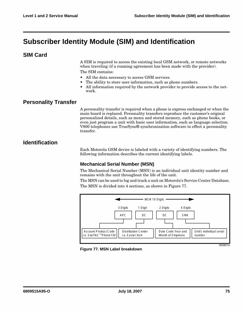
Mechanical Serial Number (MSN) The Mechanical Serial Number (MSN) is an individual unit identity number and remains with the unit throughout the life of the unit.The MSN can be used to log and track a unit on Motorola's Service Center Database.The MSN is divided into 4 sections, as shown in Figure 77.
000807a
Figure 77. MSN Label breakdown
MSN 10 Digits
3 Digits 1 Digit 2 Digits 4 Digits
APC DC DC SNR
Account Product Codei.e. StarTAC Phone130
Distribution Centeri.e. Easter Inch
Date Code: Year andMonth of Shipment
Unit's individual serialnumberTM
76 July 18, 2007 6809515A95-O
Subscriber Identity Module (SIM) and Identification V8
International Mobile Station Equipment Identity (IMEI)
The International Mobile station Equipment Identity (IMEI) number is an individual number unique to the PCB and is stored within the unit's memory.
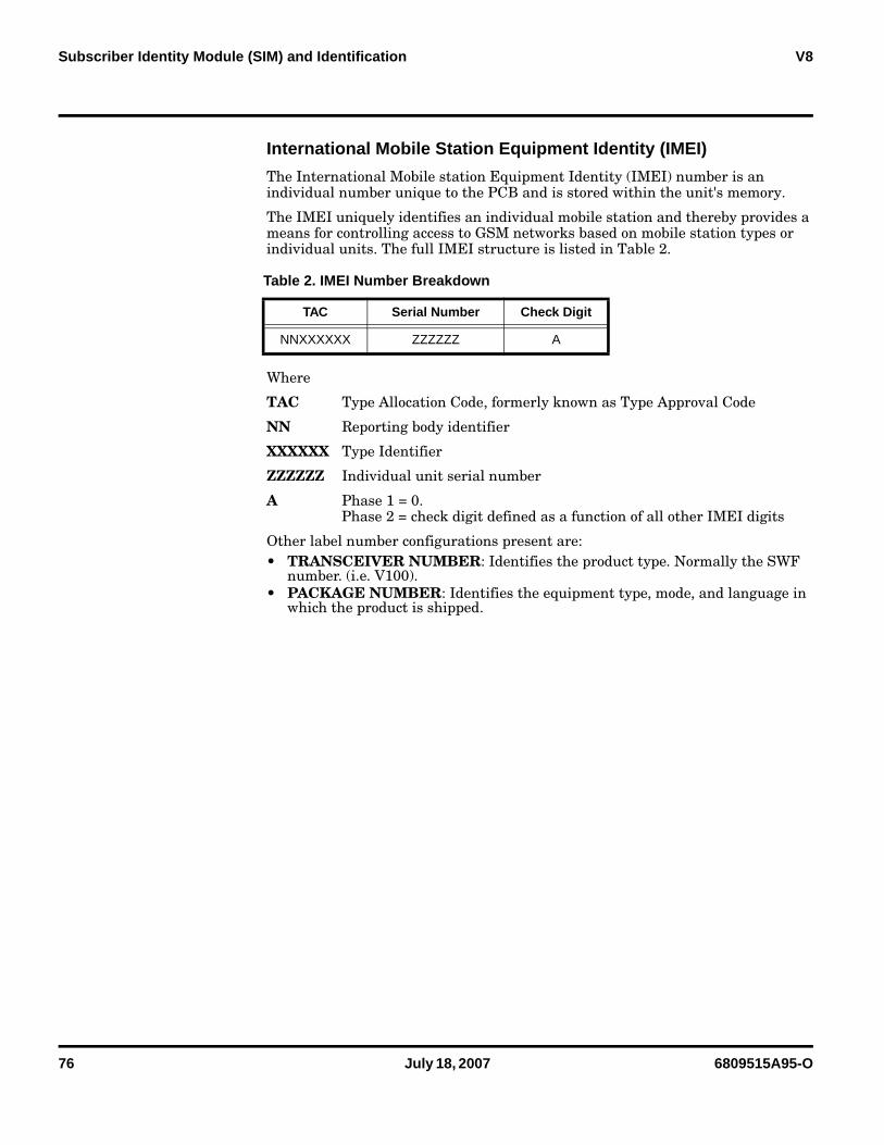
The IMEI uniquely identifies an individual mobile station and thereby provides a means for controlling access to GSM networks based on mobile station types or individual units. The full IMEI structure is listed in Table 2.
Where
TAC Type Allocation Code, formerly known as Type Approval Code
NN Reporting body identifier
XXXXXX Type Identifier
ZZZZZZ Individual unit serial number
A Phase 1 = 0. Phase 2 = check digit defined as a function of all other IMEI digits
Other label number configurations present are: • TRANSCEIVER NUMBER: Identifies the product type. Normally the SWF
number. (i.e. V100).• PACKAGE NUMBER: Identifies the equipment type, mode, and language in
which the product is shipped.
Table 2. IMEI Number Breakdown
TAC Serial Number Check Digit
NNXXXXXX ZZZZZZ A
6809515A95-O July 18, 2007 77
Level 1 and 2 Service Manual Troubleshooting
Troubleshooting
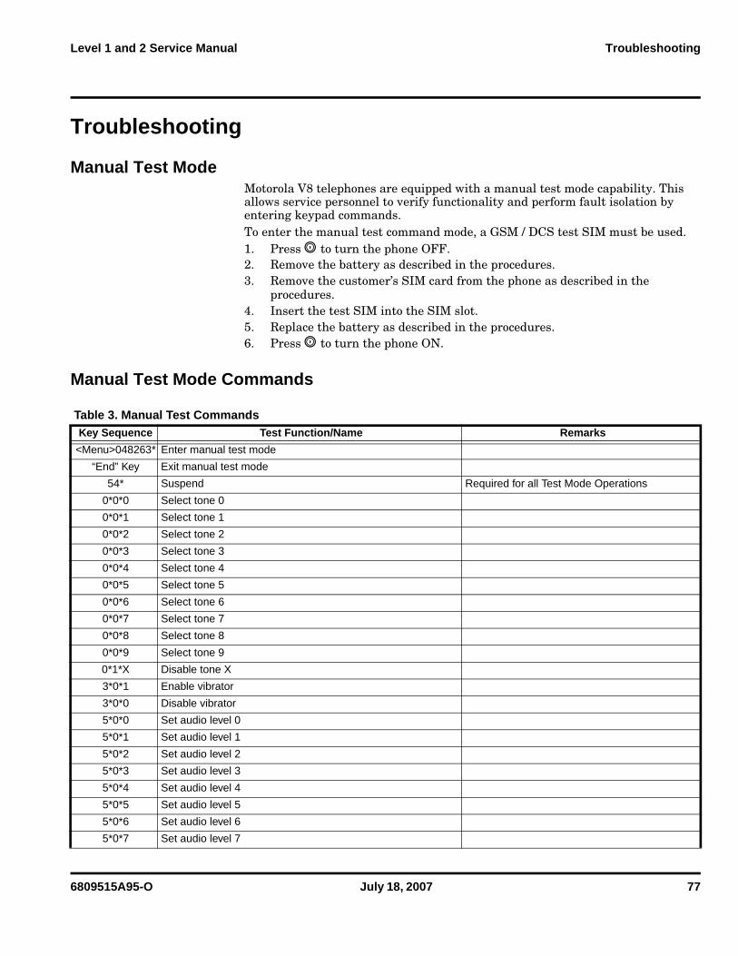
Manual Test ModeMotorola V8 telephones are equipped with a manual test mode capability. This allows service personnel to verify functionality and perform fault isolation by entering keypad commands. To enter the manual test command mode, a GSM / DCS test SIM must be used.1. Press , to turn the phone OFF.2. Remove the battery as described in the procedures.3. Remove the customer’s SIM card from the phone as described in the
procedures.4. Insert the test SIM into the SIM slot.5. Replace the battery as described in the procedures.6. Press , to turn the phone ON.
Manual Test Mode Commands
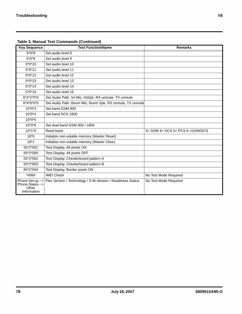
Table 3. Manual Test Commands Key Sequence Test Function/Name Remarks
<Menu>048263* Enter manual test mode
“End” Key Exit manual test mode
54* Suspend Required for all Test Mode Operations
0*0*0 Select tone 0
0*0*1 Select tone 1
0*0*2 Select tone 2
0*0*3 Select tone 3
0*0*4 Select tone 4
0*0*5 Select tone 5
0*0*6 Select tone 6
0*0*7 Select tone 7
0*0*8 Select tone 8
0*0*9 Select tone 9
0*1*X Disable tone X
3*0*1 Enable vibrator
3*0*0 Disable vibrator
5*0*0 Set audio level 0
5*0*1 Set audio level 1
5*0*2 Set audio level 2
5*0*3 Set audio level 3
5*0*4 Set audio level 4
5*0*5 Set audio level 5
5*0*6 Set audio level 6
5*0*7 Set audio level 7
78 July 18, 2007 6809515A95-O
Troubleshooting V8
5*0*8 Set audio level 8
5*0*9 Set audio level 9
5*0*10 Set audio level 10
5*0*11 Set audio level 11
5*0*12 Set audio level 12
5*0*13 Set audio level 13
5*0*14 Set audio level 14
5*0*15 Set audio level 15
6*2*2*0*0 Set Audio Path. Int Mic, IntSpk, RX unmute, TX unmute
6*4*6*0*0 Set Audio Path. Boom Mic, Boom Spk, RX unmute, TX unmute
10*0*3 Set band GSM 900
10*0*4 Set band DCS 1800
10*0*5
10*0*6 Set dual band GSM 900 / 1800
10*1*0 Read band 3= GSM 4= DCS 5= PCS 6 =GSM/DCS
18*0 Initialize non-volatile memory (Master Reset)
18*1 Initialize non-volatile memory (Master Clear)
55*2*001 Test Display. All pixels ON
55*2*000 Test Display. All pixels OFF
55*2*002 Test Display. Checkerboard pattern A
55*2*003 Test Display. Checkerboard pattern B
55*2*004 Test Display. Border pixels ON
*#06# IMEI Check No Test Mode Required
Phone Set up --> Phone Status -->
Other Information
Flex Version / Technology / S-W Version / Readiness Status No Test Mode Required
Table 3. Manual Test Commands (Continued) Key Sequence Test Function/Name Remarks
6809515A95-O July 18, 2007 79
Level 1 and 2 Service Manual Troubleshooting
Troubleshooting Chart
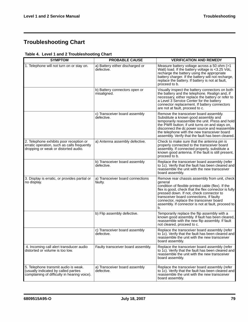
Table 4. Level 1 and 2 Troubleshooting Chart SYMPTOM PROBABLE CAUSE VERIFICATION AND REMEDY
1. Telephone will not turn on or stay on. a) Battery either discharged or defective.
Measure battery voltage across a 50 ohm (>1 Watt) load. If the battery voltage is <3.25 Vdc, recharge the battery using the appropriate battery charger. If the battery will not recharge, replace the battery. If battery is not at fault, proceed to b.
b) Battery connectors open or misaligned.
Visually inspect the battery connectors on both the battery and the telephone. Realign and, if necessary, either replace the battery or refer to a Level 3 Service Center for the battery connector replacement. If battery connectors are not at fault, proceed to c.
c) Transceiver board assembly defective.
Remove the transceiver board assembly. Substitute a known good assembly and temporarily reassemble the unit. Press and hold the PWR button; if unit turns on and stays on, disconnect the dc power source and reassemble the telephone with the new transceiver board assembly. Verify that the fault has been cleared.
2. Telephone exhibits poor reception or erratic operation, such as calls frequently dropping or weak or distorted audio.
a) Antenna assembly defective. Check to make sure that the antenna pin is properly connected to the transceiver board assembly. If connected properly, substitute a known good antenna. If the fault is still present, proceed to b.
b) Transceiver board assembly defective.
Replace the transceiver board assembly (refer to 1c). Verify that the fault has been cleared and reassemble the unit with the new transceiver board assembly.
3. Display is erratic, or provides partial or no display.
a) Transceiver board connections faulty.
Remove rear chassis assembly from unit, check generalcondition of flexible printed cable (flex). If the flex is good, check that the flex connector is fully pressed down. If not, check connector to transceiver board connections. If faulty connector, replace the transceiver board assembly. If connector is not at fault, proceed to b.
b) Flip assembly defective. Temporarily replace the flip assembly with a known good assembly. If fault has been cleared, reassemble with the new flip assembly. If fault not cleared, proceed to c.
c) Transceiver board assembly defective.
Replace the transceiver board assembly (refer to 1c). Verify that the fault has been cleared and reassemble the unit with the new transceiver board assembly.
4. Incoming call alert transducer audio distorted or volume is too low.
Faulty transceiver board assembly. Replace the transceiver board assembly (refer to 1c). Verify that the fault has been cleared and reassemble the unit with the new transceiver board assembly.
5. Telephone transmit audio is weak. (usually indicated by called parties complaining of difficulty in hearing voice).
a) Transceiver board assembly defective.
Replace the transceiver board assembly (refer to 1c). Verify that the fault has been cleared and reassemble the unit with the new transceiver board assembly.
80 July 18, 2007 6809515A95-O
Troubleshooting V8
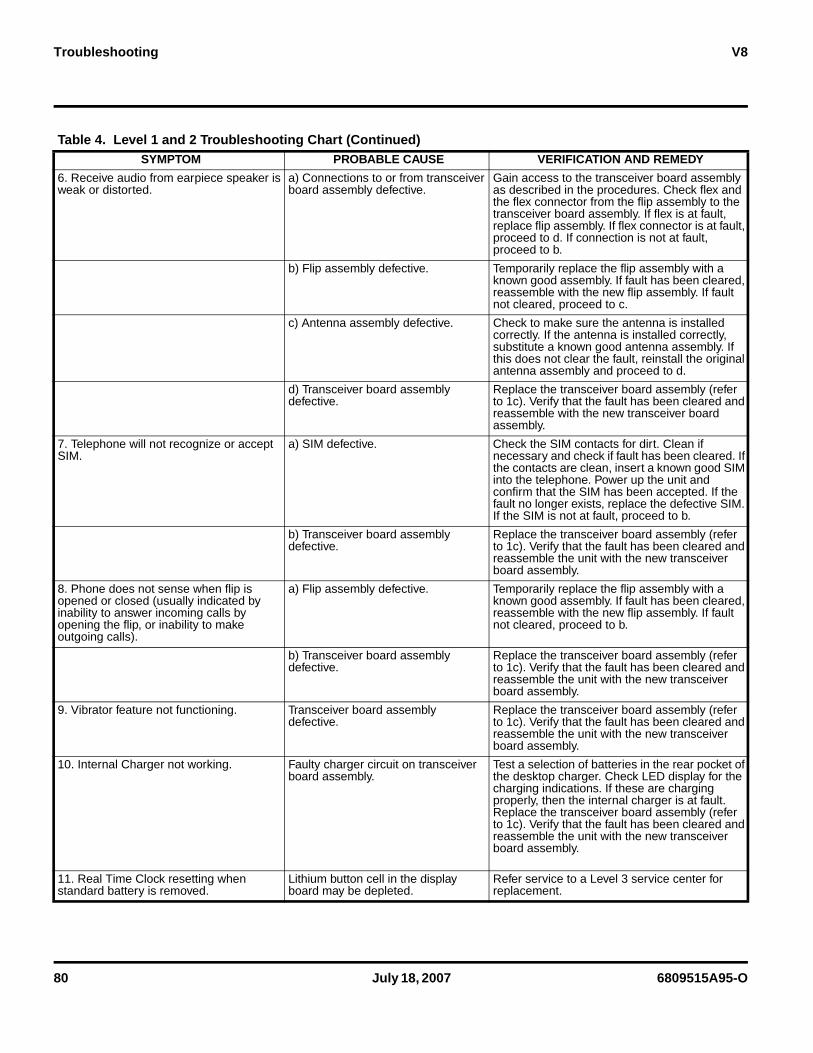
6. Receive audio from earpiece speaker is weak or distorted.
a) Connections to or from transceiver board assembly defective.
Gain access to the transceiver board assembly as described in the procedures. Check flex and the flex connector from the flip assembly to the transceiver board assembly. If flex is at fault, replace flip assembly. If flex connector is at fault, proceed to d. If connection is not at fault, proceed to b.
b) Flip assembly defective. Temporarily replace the flip assembly with a known good assembly. If fault has been cleared, reassemble with the new flip assembly. If fault not cleared, proceed to c.
c) Antenna assembly defective. Check to make sure the antenna is installed correctly. If the antenna is installed correctly, substitute a known good antenna assembly. If this does not clear the fault, reinstall the original antenna assembly and proceed to d.
d) Transceiver board assembly defective.
Replace the transceiver board assembly (refer to 1c). Verify that the fault has been cleared and reassemble with the new transceiver board assembly.
7. Telephone will not recognize or accept SIM.
a) SIM defective. Check the SIM contacts for dirt. Clean if necessary and check if fault has been cleared. If the contacts are clean, insert a known good SIM into the telephone. Power up the unit and confirm that the SIM has been accepted. If the fault no longer exists, replace the defective SIM. If the SIM is not at fault, proceed to b.
b) Transceiver board assembly defective.
Replace the transceiver board assembly (refer to 1c). Verify that the fault has been cleared and reassemble the unit with the new transceiver board assembly.
8. Phone does not sense when flip is opened or closed (usually indicated by inability to answer incoming calls by opening the flip, or inability to make outgoing calls).
a) Flip assembly defective. Temporarily replace the flip assembly with a known good assembly. If fault has been cleared, reassemble with the new flip assembly. If fault not cleared, proceed to b.
b) Transceiver board assembly defective.
Replace the transceiver board assembly (refer to 1c). Verify that the fault has been cleared and reassemble the unit with the new transceiver board assembly.
9. Vibrator feature not functioning. Transceiver board assembly defective.
Replace the transceiver board assembly (refer to 1c). Verify that the fault has been cleared and reassemble the unit with the new transceiver board assembly.
10. Internal Charger not working. Faulty charger circuit on transceiver board assembly.
Test a selection of batteries in the rear pocket of the desktop charger. Check LED display for the charging indications. If these are charging properly, then the internal charger is at fault. Replace the transceiver board assembly (refer to 1c). Verify that the fault has been cleared and reassemble the unit with the new transceiver board assembly.
11. Real Time Clock resetting when standard battery is removed.
Lithium button cell in the display board may be depleted.
Refer service to a Level 3 service center for replacement.
Table 4. Level 1 and 2 Troubleshooting Chart (Continued)SYMPTOM PROBABLE CAUSE VERIFICATION AND REMEDY
6809515A95-O July 18, 2007 81
Level 1 and 2 Service Manual Troubleshooting
Programming: Software Upgrade and FlexingContact your local technical support engineer for information about equipment and procedures for flashing and flexing.
Part Numbers The following information is provided as a reference for the parts associated with V8 telephones.
82 July 18, 2007 6809515A95-O
Troubleshooting V8
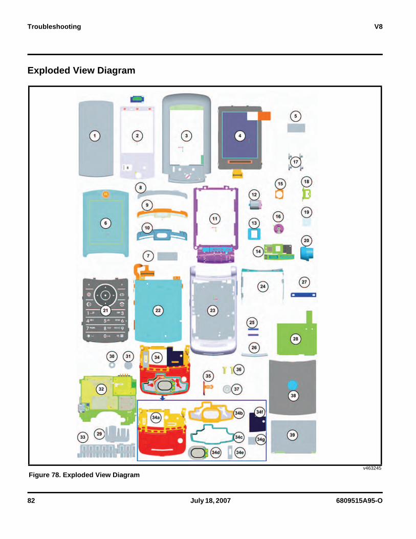
Exploded View Diagram
v463245
Figure 78. Exploded View Diagram
6809515A95-O July 18, 2007 83
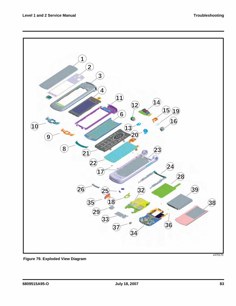
Level 1 and 2 Service Manual Troubleshooting
v470170
Figure 79. Exploded View Diagram
1
1010
2121
13132020
22221717
2626
3535
2525
33332929
37373434
1818
9
8
23
41111
6
141412121515
1616
1919
2424
2828
3636
3939
3838
2323
3232
84 July 18, 2007 6809515A95-O
Troubleshooting V8
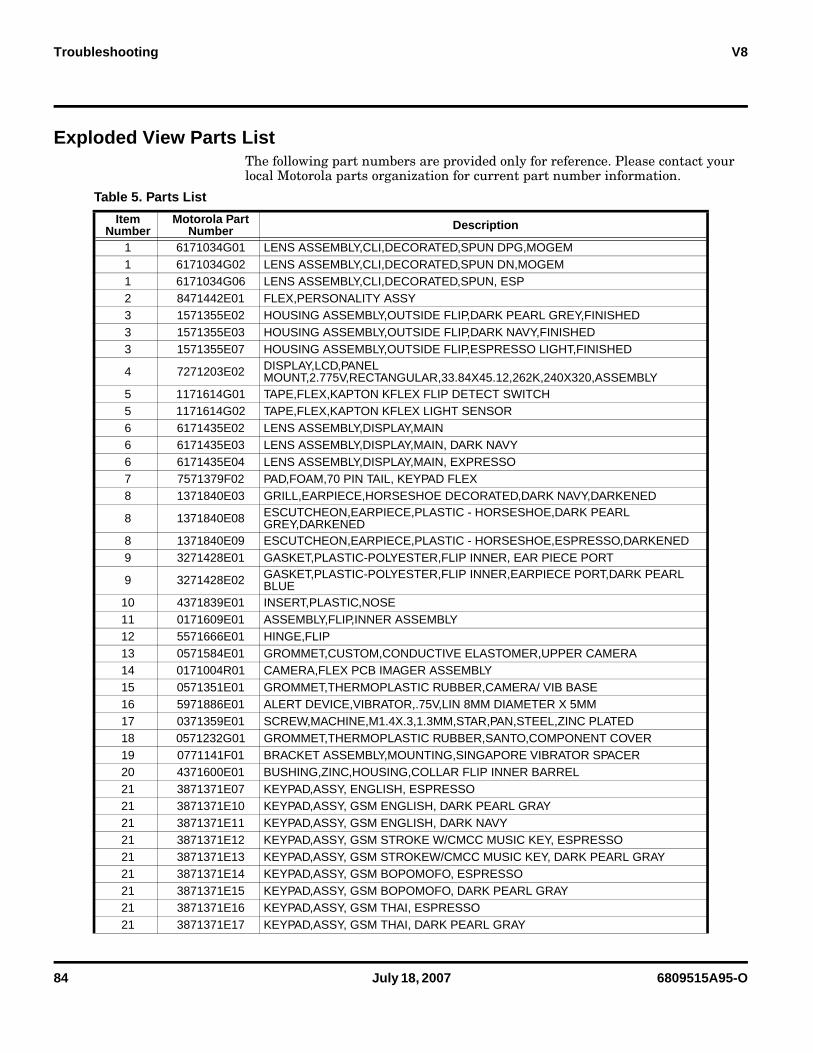
Exploded View Parts List The following part numbers are provided only for reference. Please contact your local Motorola parts organization for current part number information.
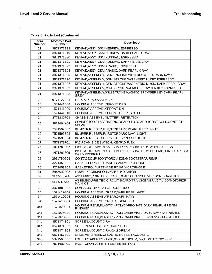
Table 5. Parts List
Item Number
Motorola Part Number Description
1 6171034G01 LENS ASSEMBLY,CLI,DECORATED,SPUN DPG,MOGEM1 6171034G02 LENS ASSEMBLY,CLI,DECORATED,SPUN DN,MOGEM1 6171034G06 LENS ASSEMBLY,CLI,DECORATED,SPUN, ESP2 8471442E01 FLEX,PERSONALITY ASSY3 1571355E02 HOUSING ASSEMBLY,OUTSIDE FLIP,DARK PEARL GREY,FINISHED3 1571355E03 HOUSING ASSEMBLY,OUTSIDE FLIP,DARK NAVY,FINISHED3 1571355E07 HOUSING ASSEMBLY,OUTSIDE FLIP,ESPRESSO LIGHT,FINISHED
4 7271203E02 DISPLAY,LCD,PANEL MOUNT,2.775V,RECTANGULAR,33.84X45.12,262K,240X320,ASSEMBLY
5 1171614G01 TAPE,FLEX,KAPTON KFLEX FLIP DETECT SWITCH5 1171614G02 TAPE,FLEX,KAPTON KFLEX LIGHT SENSOR6 6171435E02 LENS ASSEMBLY,DISPLAY,MAIN6 6171435E03 LENS ASSEMBLY,DISPLAY,MAIN, DARK NAVY6 6171435E04 LENS ASSEMBLY,DISPLAY,MAIN, EXPRESSO7 7571379F02 PAD,FOAM,70 PIN TAIL, KEYPAD FLEX8 1371840E03 GRILL,EARPIECE,HORSESHOE DECORATED,DARK NAVY,DARKENED
8 1371840E08 ESCUTCHEON,EARPIECE,PLASTIC - HORSESHOE,DARK PEARL GREY,DARKENED
8 1371840E09 ESCUTCHEON,EARPIECE,PLASTIC - HORSESHOE,ESPRESSO,DARKENED9 3271428E01 GASKET,PLASTIC-POLYESTER,FLIP INNER, EAR PIECE PORT
9 3271428E02 GASKET,PLASTIC-POLYESTER,FLIP INNER,EARPIECE PORT,DARK PEARL BLUE
10 4371839E01 INSERT,PLASTIC,NOSE11 0171609E01 ASSEMBLY,FLIP,INNER ASSEMBLY12 5571666E01 HINGE,FLIP13 0571584E01 GROMMET,CUSTOM,CONDUCTIVE ELASTOMER,UPPER CAMERA14 0171004R01 CAMERA,FLEX PCB IMAGER ASSEMBLY15 0571351E01 GROMMET,THERMOPLASTIC RUBBER,CAMERA/ VIB BASE16 5971886E01 ALERT DEVICE,VIBRATOR,.75V,LIN 8MM DIAMETER X 5MM17 0371359E01 SCREW,MACHINE,M1.4X.3,1.3MM,STAR,PAN,STEEL,ZINC PLATED18 0571232G01 GROMMET,THERMOPLASTIC RUBBER,SANTO,COMPONENT COVER19 0771141F01 BRACKET ASSEMBLY,MOUNTING,SINGAPORE VIBRATOR SPACER20 4371600E01 BUSHING,ZINC,HOUSING,COLLAR FLIP INNER BARREL21 3871371E07 KEYPAD,ASSY, ENGLISH, ESPRESSO21 3871371E10 KEYPAD,ASSY, GSM ENGLISH, DARK PEARL GRAY21 3871371E11 KEYPAD,ASSY, GSM ENGLISH, DARK NAVY21 3871371E12 KEYPAD,ASSY, GSM STROKE W/CMCC MUSIC KEY, ESPRESSO21 3871371E13 KEYPAD,ASSY, GSM STROKEW/CMCC MUSIC KEY, DARK PEARL GRAY21 3871371E14 KEYPAD,ASSY, GSM BOPOMOFO, ESPRESSO21 3871371E15 KEYPAD,ASSY, GSM BOPOMOFO, DARK PEARL GRAY21 3871371E16 KEYPAD,ASSY, GSM THAI, ESPRESSO21 3871371E17 KEYPAD,ASSY, GSM THAI, DARK PEARL GRAY
6809515A95-O July 18, 2007 85
Level 1 and 2 Service Manual Troubleshooting
21 3871371E18 KEYPAD,ASSY, GSM HEBREW, ESPRESSO21 3871371E19 KEYPAD,ASSY, GSM HEBREW, DARK PEARL GRAY21 3871371E20 KEYPAD,ASSY, GSM RUSSIAN, ESPRESSO21 3871371E21 KEYPAD,ASSY, GSM RUSSIAN, DARK PEARL GRAY21 3871371E22 KEYPAD,ASSY, GSM ARABIC, ESPRESSO21 3871371E23 KEYPAD,ASSY, GSM ARABIC, DARK PEARL GRAY21 3871371E25 KEYPAD,ASSEMBLY, GSM ENGLISH WITH BROWSER, DARK NAVY21 3871371E26 KEYPAD,ASSEMBLY, GSM STROKE W/GENERIC MUSIC ESPRESSO21 3871371E27 KEYPAD,ASSEMBLY, GSM STROKE W/GENERIC MUSIC DARK PEARL GRAY21 3871371E32 KEYPAD,ASSEMBLY,GSM STROKE W/CMCC BROWSER KEY,ESPRESSO
21 3871371E33 KEYPAD,ASSEMBLY,GSM STROKE W/CMCC BROWSER KEY,DARK PEARL GREY
22 0171127R01 FLEX,KEYPAD,ASSEMBLY23 1571441E08 HOUSING ASSEMBLY,FRONT, DPG23 1571441E09 HOUSING ASSEMBLY,FRONT, DN23 1571441E10 HOUSING ASSEMBLY,FRONT, ESPRESSO LITE24 2771230F03 CHASSIS ASSEMBLY,BATTERY,RETENTION
25 3987404Y04 CONNECTOR ELASTOMERIC,BOARD TO BOARD,1CONT,GOLD,CONTACT SPEAKER
26 7571599E02 BUMPER,RUBBER,FLIP,STOP,DARK PEARL GREY LIGHT26 7571599E03 BUMPER,RUBBER,FLIP,STOP,DARK NAVY LIGHT26 7571599E04 BUMPER,RUBBER,FLIP,STOP,ESPRESSO LIGHT27 7571379F01 PAD,FOAM,SIDE SWITCH, KEYPAD FLEX28 1471201F02 INSULATOR,TAPE,PLASTIC-POLYESTER,BATTERY WITH PULL TAB
28 1471201F09 INSULATOR,TAPE,PLASTIC-POLYESTER,BATTERY, PULLTAB, CIRCULAR, SIM CARD PREPRINT
29 3971796G01 CONTACT,CLIP,3CONT,GROUNDING BOOTSTRAP, REAR30 3271459E01 GASKET,POLYURETHANE FOAM,MICROPHONE30 3271459E02 GASKET,POLYURETHANE FOAM MICROPHONE31 5485042F02 LABEL,INFORMATION,WATER INDICATOR32 SLG5155AA- ASSEMBLY,PRINTED CIRCUIT BOARD,TRANSCEIVER,GSM BOARD KIT
32 SLG5327AA- ASSEMBLY,PRINTED CIRCUIT BOARD,TRANSCEIVER,V9,T-LIDO/MOTORIZR MAIN KIT
33 3971888E02 CONTACT,CLIP,XCVR GROUND LIDO34 1571419G02 HOUSING ASSEMBLY,REAR,DARK PEARL GREY34 1571419G03 HOUSING ASSEMBLY,REAR,DARK NAVY34 1571419G04 HOUSING ASSEMBLY,REAR,ESPRESSO
34a 1571026G01 HOUSING,REAR,PLASTIC - POLYCARBONATE,DARK PEARL GREY,IM FINISHED
34a 1571026G02 HOUSING,REAR,PLASTIC - POLYCARBONATE,DARK NAVY,IM FINISHED34a 1571026G03 HOUSING,REAR,PLASTIC - POLYCARBONATE,ESPRESSO,IM FINISHED34b 3571374E01 SCREEN,ACOUSTIC,RH34b 3571374E02 SCREEN,ACOUSTIC,RH,DARK BLUE34b 3571374E04 SCREEN,ACOUSTIC,RH,CALI DREAM34c 0571457E01 GROMMET,THERMOPLASTIC RUBBER,ACOUSTIC34d 5071508D03 LOUDSPEAKER,DYNAMIC,600-7000,8OHM,.5W,CONTACT,3X14X2034e 7571680F01 PAD, PORON 70 PIN K-FLEX RETENTION
Table 5. Parts List (Continued)
Item Number
Motorola Part Number Description
86 July 18, 2007 6809515A95-O
Troubleshooting V8
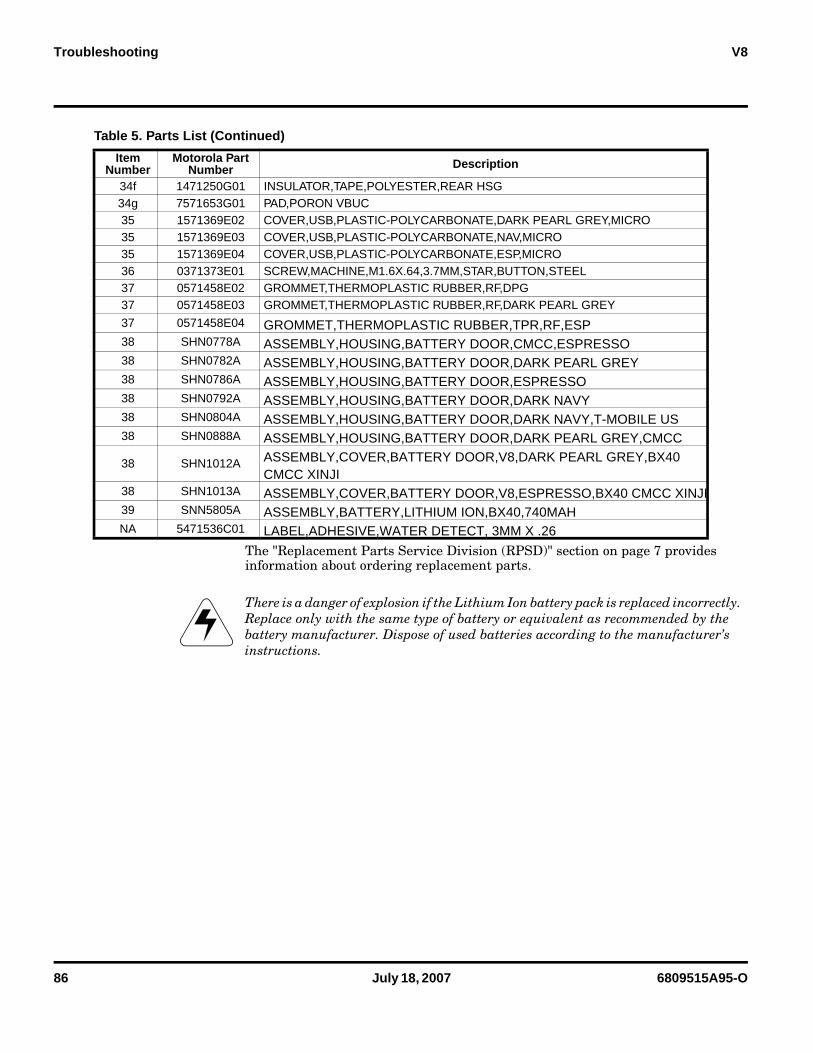
The "Replacement Parts Service Division (RPSD)" section on page 7 provides information about ordering replacement parts.
34f 1471250G01 INSULATOR,TAPE,POLYESTER,REAR HSG34g 7571653G01 PAD,PORON VBUC35 1571369E02 COVER,USB,PLASTIC-POLYCARBONATE,DARK PEARL GREY,MICRO35 1571369E03 COVER,USB,PLASTIC-POLYCARBONATE,NAV,MICRO35 1571369E04 COVER,USB,PLASTIC-POLYCARBONATE,ESP,MICRO36 0371373E01 SCREW,MACHINE,M1.6X.64,3.7MM,STAR,BUTTON,STEEL37 0571458E02 GROMMET,THERMOPLASTIC RUBBER,RF,DPG37 0571458E03 GROMMET,THERMOPLASTIC RUBBER,RF,DARK PEARL GREY
37 0571458E04 GROMMET,THERMOPLASTIC RUBBER,TPR,RF,ESP38 SHN0778A ASSEMBLY,HOUSING,BATTERY DOOR,CMCC,ESPRESSO38 SHN0782A ASSEMBLY,HOUSING,BATTERY DOOR,DARK PEARL GREY38 SHN0786A ASSEMBLY,HOUSING,BATTERY DOOR,ESPRESSO38 SHN0792A ASSEMBLY,HOUSING,BATTERY DOOR,DARK NAVY38 SHN0804A ASSEMBLY,HOUSING,BATTERY DOOR,DARK NAVY,T-MOBILE US38 SHN0888A ASSEMBLY,HOUSING,BATTERY DOOR,DARK PEARL GREY,CMCC
38 SHN1012A ASSEMBLY,COVER,BATTERY DOOR,V8,DARK PEARL GREY,BX40 CMCC XINJI
38 SHN1013A ASSEMBLY,COVER,BATTERY DOOR,V8,ESPRESSO,BX40 CMCC XINJI39 SNN5805A ASSEMBLY,BATTERY,LITHIUM ION,BX40,740MAHNA 5471536C01 LABEL,ADHESIVE,WATER DETECT, 3MM X .26
EThere is a danger of explosion if the Lithium Ion battery pack is replaced incorrectly. Replace only with the same type of battery or equivalent as recommended by the battery manufacturer. Dispose of used batteries according to the manufacturer’s instructions.
Table 5. Parts List (Continued)
Item Number
Motorola Part Number Description
6809515A95-O July 18, 2007 87
Level 1 and 2 Service Manual Troubleshooting
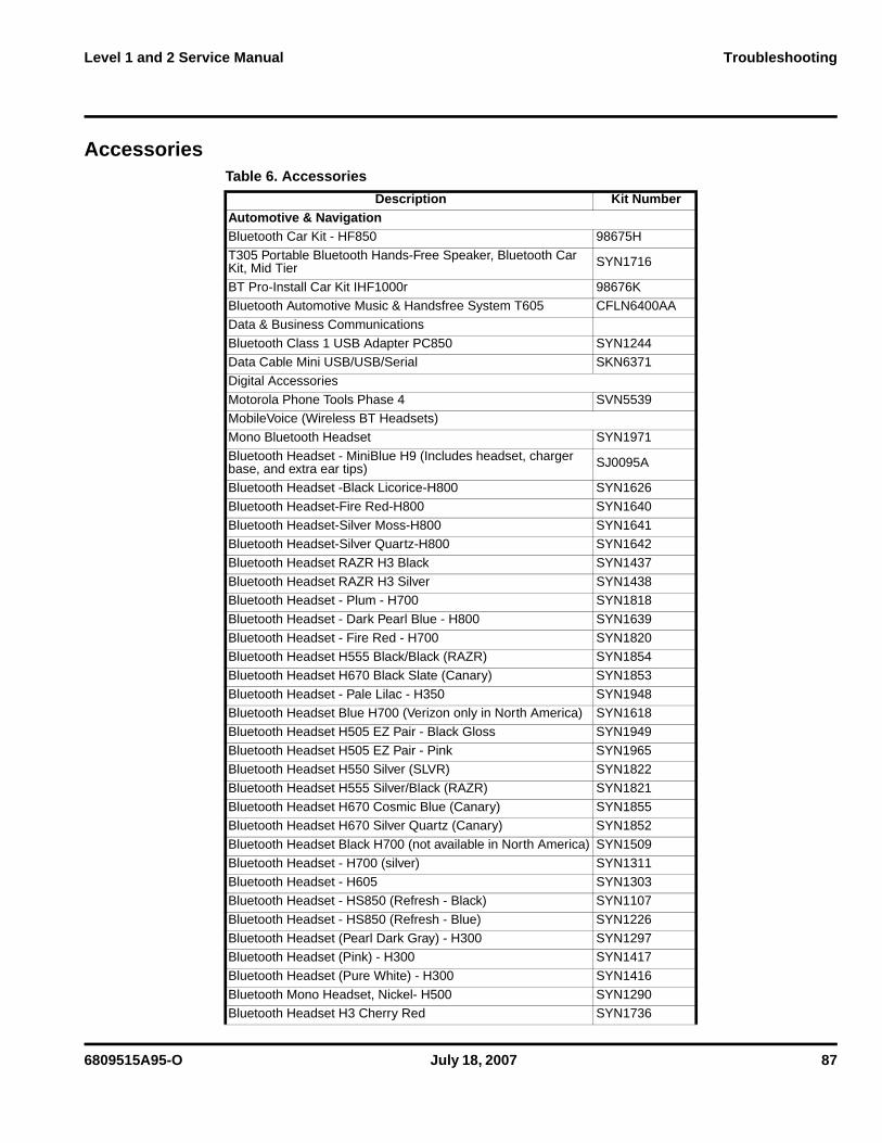
AccessoriesTable 6. Accessories
Description Kit NumberAutomotive & NavigationBluetooth Car Kit - HF850 98675H
T305 Portable Bluetooth Hands-Free Speaker, Bluetooth Car Kit, Mid Tier SYN1716
BT Pro-Install Car Kit IHF1000r 98676KBluetooth Automotive Music & Handsfree System T605 CFLN6400AA
Data & Business Communications
Bluetooth Class 1 USB Adapter PC850 SYN1244Data Cable Mini USB/USB/Serial SKN6371
Digital Accessories
Motorola Phone Tools Phase 4 SVN5539MobileVoice (Wireless BT Headsets)
Mono Bluetooth Headset SYN1971
Bluetooth Headset - MiniBlue H9 (Includes headset, charger base, and extra ear tips) SJ0095A
Bluetooth Headset -Black Licorice-H800 SYN1626
Bluetooth Headset-Fire Red-H800 SYN1640
Bluetooth Headset-Silver Moss-H800 SYN1641Bluetooth Headset-Silver Quartz-H800 SYN1642
Bluetooth Headset RAZR H3 Black SYN1437
Bluetooth Headset RAZR H3 Silver SYN1438Bluetooth Headset - Plum - H700 SYN1818
Bluetooth Headset - Dark Pearl Blue - H800 SYN1639
Bluetooth Headset - Fire Red - H700 SYN1820Bluetooth Headset H555 Black/Black (RAZR) SYN1854
Bluetooth Headset H670 Black Slate (Canary) SYN1853
Bluetooth Headset - Pale Lilac - H350 SYN1948Bluetooth Headset Blue H700 (Verizon only in North America) SYN1618
Bluetooth Headset H505 EZ Pair - Black Gloss SYN1949
Bluetooth Headset H505 EZ Pair - Pink SYN1965Bluetooth Headset H550 Silver (SLVR) SYN1822
Bluetooth Headset H555 Silver/Black (RAZR) SYN1821
Bluetooth Headset H670 Cosmic Blue (Canary) SYN1855Bluetooth Headset H670 Silver Quartz (Canary) SYN1852
Bluetooth Headset Black H700 (not available in North America) SYN1509
Bluetooth Headset - H700 (silver) SYN1311Bluetooth Headset - H605 SYN1303
Bluetooth Headset - HS850 (Refresh - Black) SYN1107
Bluetooth Headset - HS850 (Refresh - Blue) SYN1226
Bluetooth Headset (Pearl Dark Gray) - H300 SYN1297Bluetooth Headset (Pink) - H300 SYN1417
Bluetooth Headset (Pure White) - H300 SYN1416
Bluetooth Mono Headset, Nickel- H500 SYN1290Bluetooth Headset H3 Cherry Red SYN1736
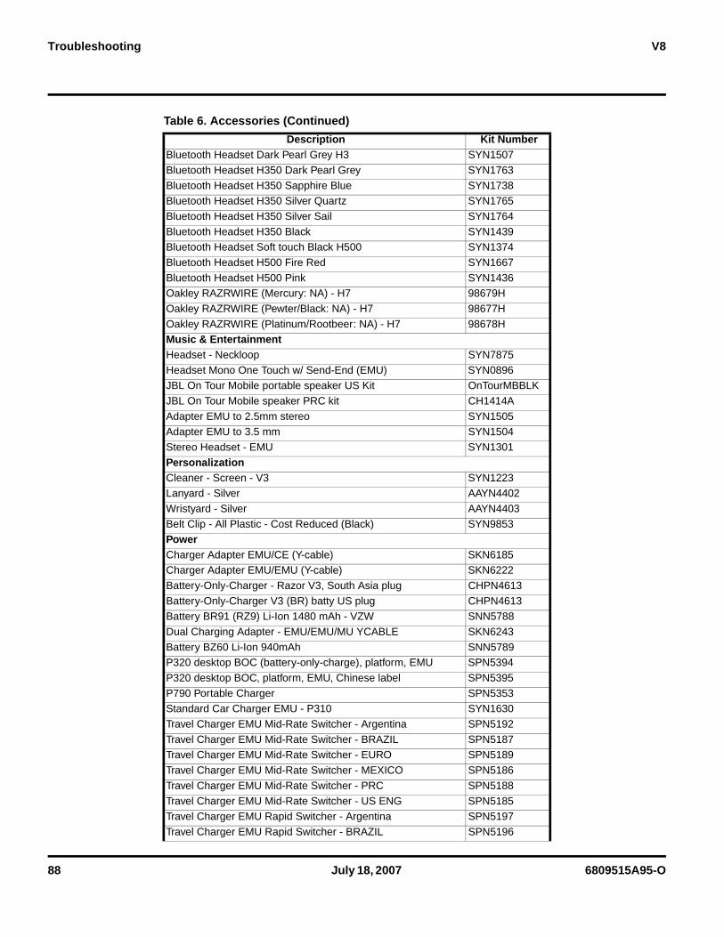
88 July 18, 2007 6809515A95-O
Troubleshooting V8
Bluetooth Headset Dark Pearl Grey H3 SYN1507
Bluetooth Headset H350 Dark Pearl Grey SYN1763
Bluetooth Headset H350 Sapphire Blue SYN1738Bluetooth Headset H350 Silver Quartz SYN1765
Bluetooth Headset H350 Silver Sail SYN1764
Bluetooth Headset H350 Black SYN1439Bluetooth Headset Soft touch Black H500 SYN1374
Bluetooth Headset H500 Fire Red SYN1667
Bluetooth Headset H500 Pink SYN1436Oakley RAZRWIRE (Mercury: NA) - H7 98679H
Oakley RAZRWIRE (Pewter/Black: NA) - H7 98677H
Oakley RAZRWIRE (Platinum/Rootbeer: NA) - H7 98678HMusic & EntertainmentHeadset - Neckloop SYN7875
Headset Mono One Touch w/ Send-End (EMU) SYN0896JBL On Tour Mobile portable speaker US Kit OnTourMBBLK
JBL On Tour Mobile speaker PRC kit CH1414A
Adapter EMU to 2.5mm stereo SYN1505Adapter EMU to 3.5 mm SYN1504
Stereo Headset - EMU SYN1301
PersonalizationCleaner - Screen - V3 SYN1223
Lanyard - Silver AAYN4402
Wristyard - Silver AAYN4403Belt Clip - All Plastic - Cost Reduced (Black) SYN9853
PowerCharger Adapter EMU/CE (Y-cable) SKN6185Charger Adapter EMU/EMU (Y-cable) SKN6222
Battery-Only-Charger - Razor V3, South Asia plug CHPN4613
Battery-Only-Charger V3 (BR) batty US plug CHPN4613Battery BR91 (RZ9) Li-Ion 1480 mAh - VZW SNN5788
Dual Charging Adapter - EMU/EMU/MU YCABLE SKN6243
Battery BZ60 Li-Ion 940mAh SNN5789P320 desktop BOC (battery-only-charge), platform, EMU SPN5394
P320 desktop BOC, platform, EMU, Chinese label SPN5395
P790 Portable Charger SPN5353Standard Car Charger EMU - P310 SYN1630
Travel Charger EMU Mid-Rate Switcher - Argentina SPN5192
Travel Charger EMU Mid-Rate Switcher - BRAZIL SPN5187Travel Charger EMU Mid-Rate Switcher - EURO SPN5189
Travel Charger EMU Mid-Rate Switcher - MEXICO SPN5186
Travel Charger EMU Mid-Rate Switcher - PRC SPN5188
Travel Charger EMU Mid-Rate Switcher - US ENG SPN5185Travel Charger EMU Rapid Switcher - Argentina SPN5197
Travel Charger EMU Rapid Switcher - BRAZIL SPN5196
Table 6. Accessories (Continued)
Description Kit Number
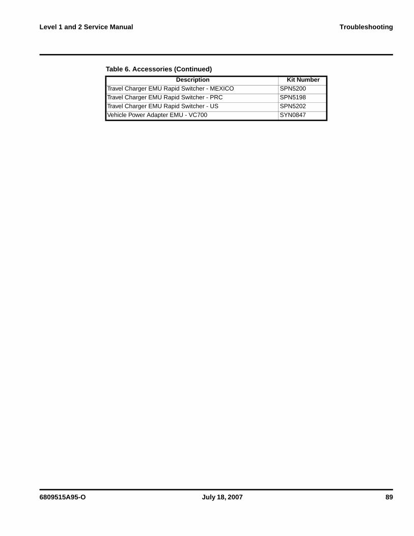
6809515A95-O July 18, 2007 89
Level 1 and 2 Service Manual Troubleshooting
Travel Charger EMU Rapid Switcher - MEXICO SPN5200
Travel Charger EMU Rapid Switcher - PRC SPN5198
Travel Charger EMU Rapid Switcher - US SPN5202Vehicle Power Adapter EMU - VC700 SYN0847
Table 6. Accessories (Continued)
Description Kit Number

90 July 18, 2007 6809515A95-O
Troubleshooting V8
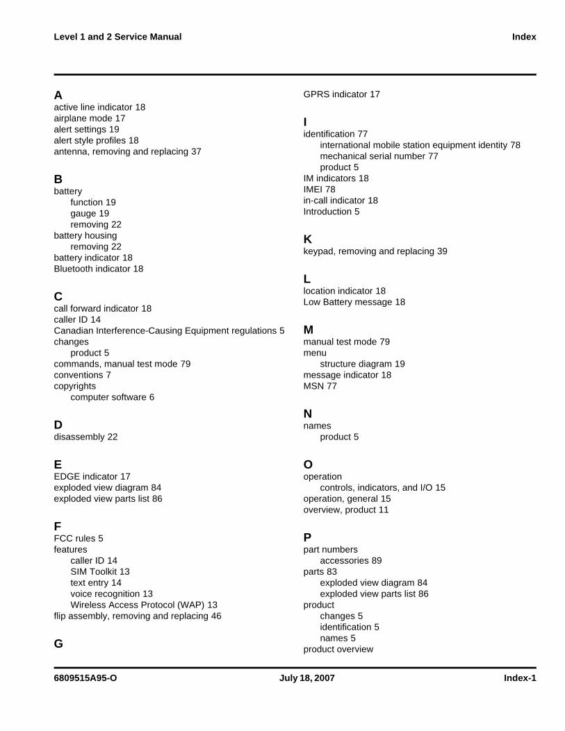
6809515A95-O July 18, 2007 Index-1
Level 1 and 2 Service Manual Index
Aactive line indicator 18airplane mode 17alert settings 19alert style profiles 18antenna, removing and replacing 37
Bbattery
function 19gauge 19removing 22
battery housingremoving 22
battery indicator 18Bluetooth indicator 18
Ccall forward indicator 18caller ID 14Canadian Interference-Causing Equipment regulations 5changes
product 5commands, manual test mode 79conventions 7copyrights
computer software 6
Ddisassembly 22
EEDGE indicator 17exploded view diagram 84exploded view parts list 86
FFCC rules 5features
caller ID 14SIM Toolkit 13text entry 14voice recognition 13Wireless Access Protocol (WAP) 13
flip assembly, removing and replacing 46
G
GPRS indicator 17
Iidentification 77
international mobile station equipment identity 78mechanical serial number 77product 5
IM indicators 18IMEI 78in-call indicator 18Introduction 5
Kkeypad, removing and replacing 39
Llocation indicator 18Low Battery message 18
Mmanual test mode 79menu
structure diagram 19message indicator 18MSN 77
Nnames
product 5
Ooperation
controls, indicators, and I/O 15operation, general 15overview, product 11
Ppart numbers
accessories 89parts 83
exploded view diagram 84exploded view parts list 86
productchanges 5identification 5names 5
product overview
1 and 2IndexV86809515A95-O
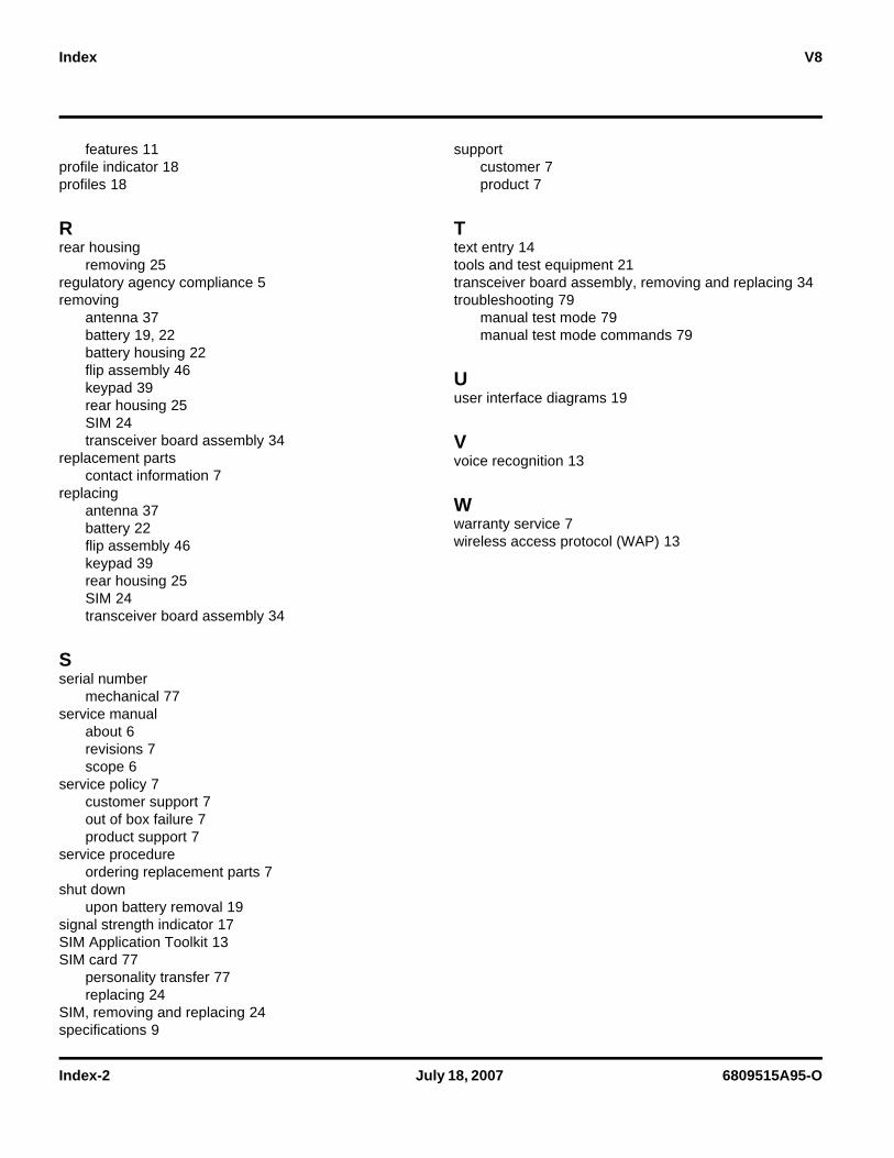
Index-2 July 18, 2007 6809515A95-O
Index V8
features 11profile indicator 18profiles 18
Rrear housing
removing 25regulatory agency compliance 5removing
antenna 37battery 19, 22battery housing 22flip assembly 46keypad 39rear housing 25SIM 24transceiver board assembly 34
replacement partscontact information 7
replacingantenna 37battery 22flip assembly 46keypad 39rear housing 25SIM 24transceiver board assembly 34
Sserial number
mechanical 77service manual
about 6revisions 7scope 6
service policy 7customer support 7out of box failure 7product support 7
service procedureordering replacement parts 7
shut downupon battery removal 19
signal strength indicator 17SIM Application Toolkit 13SIM card 77
personality transfer 77replacing 24
SIM, removing and replacing 24specifications 9
supportcustomer 7product 7
Ttext entry 14tools and test equipment 21transceiver board assembly, removing and replacing 34troubleshooting 79
manual test mode 79manual test mode commands 79
Uuser interface diagrams 19
Vvoice recognition 13
Wwarranty service 7wireless access protocol (WAP) 13