Embed Size (px)
Citation preview

Brought to you by PCS Electronics, www.pcs-electronics.com
SE6000AN+ High performance FM stereo encoder with 114x oversampling
Manual

Brought to you by PCS Electronics, www.pcs-electronics.com
IMPORTANT NOTE
Upon receiving your order inspect the packaging material and unit for apparent damage.
Any damage should be reported immediately so we can make a claim with the shipping
company. Take photos, if you can, they can be used as a proof.
Mains cable is typically not included with our mains power supplies and units. Since these
cables vary from country to country and we had trouble finding the exact type we decided
against including them, especially since finding them is so easy and cheap locally. They
can be obtained in any radio/computer/hardware shop at the cost of about 1 US$. It is the
type used in your PC for mains power.
Study local regulations and ensure you are operating in compliance.
Never ever operate any transmitter or amplifier without a properly tuned antenna!

Brought to you by PCS Electronics, www.pcs-electronics.com
Table of Contents
Introducing the SE6000AN+ stereo encoder ............................ 1
Why is SE6000AN+ so great?......................................................... 1
Technical specifications: ................................................................. 2
How is SE6000+ better than SE2000?............................................ 2
Thank you for purchasing SE6000 AN+ stereo encoder ................. 2
SE6000AN+ board layout......................................................... 3
Board layout.................................................................................... 3
Drill template ................................................................................... 5
What’s under the hood? ........................................................... 6
INTRODUCTION - PRINCIPLES OF OPERATION ........................ 6
Some facts about stereo ................................................................. 7
The transmitter................................................................................ 7
The receiver .................................................................................... 7
Circuit description ........................................................................... 7
Before you start........................................................................ 8
Mains power supply and mains power cable................................... 8
Enclosure ........................................................................................ 8
Balanced audio and power connector ............................................. 8
Digital audio streaming.................................................................... 9
Stereo/mono mode selection and maxlink connector...................... 9
Setup and testing ................................................................... 10
Setting up levels............................................................................ 10
Troubleshooting ..................................................................... 11
Troubleshooting ............................................................................ 11
Appendix A: Connecting stereo encoder to MAXPRO FM exciter .................................................................................... 13
Appendix B: Connecting VUMAX-1 ........................................ 14
Appendix C: Complete FM transmitter block by block ............ 15
Appendix D: General tips for setting up transmitters............... 18
Typical FM transmitter setups ....................................................... 18
Typical FM broadcasting antenna setups...................................... 19

Brought to you by PCS Electronics, www.pcs-electronics.com
Wiring antennas in multi-bay configurations.................................. 20
Appendix E – Using wireless audio links ................................ 21
Appendix F – Warranty and legal info..................................... 22
Important notice! ........................................................................... 22
Warranty and servicing! ................................................................ 22
Legal info ...................................................................................... 22
Limitation of liability....................................................................... 22
Also available from www.pcs-electronics.com .............................. 23
Revisions and errata .............................................................. 24
Index ...................................................................................... 25

Brought to you by PCS Electronics, www.pcs-electronics.com
Introducing the SE6000AN+ stereo encoder
With digital audio input (U+) for completely noise-free audio experience
he new SE6000AN+ is a high performance stereo encoder with split supply rails (via on-board DC/DC), analog
balanced input buffers, a fairly complex and incredibly sharp filter with deep notch at 19KHz, preemphasis, limiter
and LC MPX filter. Digital subsystem generates 19KHz pilot (32xoversampling) and generate DSB signal. 114x
oversampled MPX ensures crisp stereo sound with incredible stereo separation. You never thought analog audio
filters could be this sharp, but they are; thanks to elaborate filter design. You really have to hear it to believe it. SE6000 AN+
can even be upgraded to RDS functionality simply by plugging-in a RDS IO board. It is perfect for a demanding, but cost-
conscious broadcaster.
SE6000+ will make sure your signal stays where you want it, providing high quality audio with excellent channel separation
without causing interference to nearby channels. High quality components and printed circuit board assure 24/7 operation
for years. In this manual you will find all of its exciting secrets.
Why is SE6000AN+ so great?
- Perfect for any mono FM transmitter
- Mix of analog/digital technology produces crisp natural sounding audio
- When digital audio input is used you can enjoy completely noise-free audio. Ground loops are gone. You have to hear it to believe it. You can now stream audio digitally directly from your PC/Laptop.
- Extremely sharp 15kHz low pass filters and a very deep notch at 19KHz!
- Telemetry output that connects to MAX PRO 5015, 5025, 5040 or 5050 transmitters.
- Does not require LCD module, but can be connected to LCD module of our exciters for stereo/mono control!
- Balanced or unbalanced audio inputs. This effectively eliminates annoying ground loops and hum.
- LC filtered MPX output signal.
- Built-in limiter, low pass filter and true compressor.
- Incredibly good stereo separation
- Support for RDS daughter board for easy upgrade to RDS
- MPXin/MPXout jumper added for professional setups
- VU meter 3-pin jumper for easy upgrade to VU-meter
- ECPD technology (Extremely Cute PCB Design; you’ve got to admit, it’s a beauty)
- All SMD design, machine placed, washed in ultrasound bath, professionally looking.
Chapter
1
T

Brought to you by PCS Electronics, www.pcs-electronics.com
Technical specifications:
Audio Response: 10Hz-15KHz, 15kHz lowpass filtered (standards require upper level at 15KHz max)
19KHz notch filter, >-60 dB typ
Precise pre-emphasis, 50uS, 75uS or none
Audio Input Impedance: 10K, balanced or unbalanced
Audio Input Level: 0 dB
Digital audio input: USB connector, Windows/Linux/Mac compatible
Distortion: <0.01%
S/N ratio: >85 dB
Separation: >70 dB typ. (more than any radio receiver you can buy on the market)
Pilot Frequency: 19 KHz, DSP generated with 32x oversampling
Output Impedance: 75 Ohms
Power Requirements: 12-15VDC / 160-200mA
PC Board Size: 100x85mm
Audio connectors: all RCA jacks are mounted on the board, 3-pin jumper for XLR balanced input
Power connector: 2.1mm power socket, center is positive, connection terminals (easier for boxed units)
Output level: Ueff 4V, 2V or 1V
How is SE6000+ better than SE2000?
- Higher oversampling and resulting better separation and cleaner MPX signal
- New form factor with on-board telemetry output
- Side adjustable trimmers for MPX out and MPX in
- Accepts new IO board with RDS, XLR connectors and BNC for MPXin, MPXout, 19KHz.
Thank you for purchasing SE6000 AN+ stereo encoder
We hope you will enjoy it as much as we do and if you do remember to tell your friends and colleagues about it. Please feel
free to leave your comments at our website or post your experience in our forum. And if you encounter a problem please let
us know so that we may improve our products, offer advice and suggestion. From all of us we wish you happy broadcasting!
Your PCS Electronics team
Brought to you by PCS Electronics, www.pcs-electronics.com
SE6000AN+ board layout
Board layout
Fig. 1: SE6000+ board layout
Chapter
2

Brought to you by PCS Electronics, www.pcs-electronics.com
Ref. Function
A Digital audio input, USB
B,D Left and right analog audio input, RCA
C Left and right XLR header connector, either connects to IO board or via wires direct to XLR connectors
E MPX out level, adjustable from inside (make holes into enclosure)
F MPX in level, adjustable from inside (make holes into enclosure)
G USB header, you can connect external USB connector, if needed
H Telemetry connector. For this to work you have to use MAX PRO 5015 series FM exciter and you have to
connect header I to this exciter via 10-lead flat cable.
I When using our FM exciter with telemetry header such as MAX PRO 5015 series you have to connect this
header to the exciter via 10-lead flat cable.
J Pre-emphasis. Use these two jumpers to set pre-emphasis. This can either be 50uS (EU and most of the world) or
75uS (USA). If you do not install jumper there will be no pre-emphasis.
K 19KHz pilot accuracy can be set here.
L Stereo pilot level adjustment trimmer.
M You can connect VUMAX-1 led vu-meter unit here, it will show audio levels as bar graphs. The 2 remaining bar
graphs can be connected to FM exciter to show power and SWR.
N Connects to optional IO board with RDS. It contains many usefull signals, if you want to experiment. It contains
19KHz signal in square form, +5V, RX and TX for RS232, MPXout and MPXin.
O Power supply, 12-15V DC, 100mA max, stabilized
P MPX out, this goes to FM exciter audio input.
Z Maxlink connector. If you are using MAXPRO series of FM exciters, connect this to the RF board via flat cable.
This cable will also provide supply voltage so you do not need to connect anything to J7.
X Power supply voltage, only use if you did not use MAXLINK cable.
Y Stereo jumper, only install if you are not using MAXLINK cable.
Table 1: Description of various elements of the SE6000 AN+ stereo encoder board

Brought to you by PCS Electronics, www.pcs-electronics.com
Drill template
COMING SOON Fig. 2: Stereo encoder drill template, all measurements in mm, all holes are for M3 metric screws. Board is usually mounted with distancers about 10mm high. Place metal distancer under 7805 to allow some heatsinking.

Brought to you by PCS Electronics, www.pcs-electronics.com
What’s under the hood?
INTRODUCTION - PRINCIPLES OF OPERATION
Fig. 3: Theoretical frequency spectrum of the stereo multiplexed signal
Figure 3 above shows the theoretical frequency spectrum of the stereo multiplex signal (MPX-signal). The MONO signal on
the far left goes from approx. 20Hz to 15KHz and is used to transmit the sum of both the left and right channel. This
assures compatibility with older MONO receivers that only receive this part of the spectrum. Going from left to the right we
stumble upon the 19 KHz pilot just above the MONO signal. This pilot has a couple of functions;
1.) It signals presence of the stereo signal; by detecting it the receiver switches to stereo
2.) It enables demodulation of the L-R signal and LEFT/RIGHT channel reconstruction
The 19 KHz signal is used to demodulate the DSB (Double Side Band Suppressed Carrier) signal stretching from 23 KHz to
53 KHz. This signal contains the L-R information (difference between the left and right audio channel). This is what the
stereo encoder does to generate the Stereo Multiplex signal:
A.) Add Left and Right signals to get an L+R signal.
B.) Generate a Pilot Tone of 19 KHz.
C.) Generate a 38 KHz carrier for the Doubly Balanced Mixer (DBM)
D.) Generate the L-R (difference of the audio channels) signal for the DBM
E.) Modulate the 38 KHz carrier with the L-R signal using DBM (DBM suppresses the carrier in the process)
F.) Add up A, B and C above to get the complete MPX Signal.
G.) Use the above MPX signal to Frequency Modulate a carrier in the 87.5-108 MHz band.
Chapter
3

Brought to you by PCS Electronics, www.pcs-electronics.com
Some facts about stereo
Even the best stereo encoder is by itself not enough to guarantee good channel separation at the receiving side over the
whole audio frequency range. Many factors are involved:
The transmitter
The first problems usually occur at the transmitter. Badly designed audio stages of the modulator will produce low frequency
phase shifts, affecting separation. But the main problem is the phase locked loop section of the transmitter. PLL tries to
correct the frequency deviations caused by the audio effectively canceling modulation. The frequency correcting signal is
passed through a low pass filter (loop filter). This loop filter dampens (smoothes and averages) the correcting pulses from the
PLL circuit before passing the corrected voltage to the frequency control part of the modulator. The loop filter is usually the
cause of the phase shifts due to not being able to sufficiently dampen and smooth the correcting pulses when the transmitter
is fed with low frequencies. Variable frequency oscillators do not suffer from the problem at all due to no frequency
correcting circuits (PLL). In short, a badly designed transmitter can be hugely detrimental to the stereo signal created by a
stereo encoder Do not jump to the conclusion that the stereo sound that you are listening to is the stereo encoder only.
The receiver
Filter Bandwidth and Stereo Decoder of a receiver. Even if the transmitter adds no phase shifts to the multiplex signal
transmitted, the receiver (radio) at the listening end can still cause trouble. The filters in the radio can cause phase shifts to the
multiplex if too narrow in bandwidth. Many cheaper tuners have less filtering (less manufacturing cost) which although not
great for selectivity provides for excellent separation in strong signal environments. The above is only true if the stereo
decoder in the radio or tuner is ok. It is very hard to obtain any modern stereo decoder chips that give more than 35 dB of
separation, some even give you only 25 dB. So even with modern day DSP (digital signal processor) stereo encoders which
achieve separation of more than 70 dB, you will never hear it because the radio you will be listening to on will only allow 35
db at best. As you see, stereo is not just about a stereo encoder!
Circuit description
Left and Right audio signals are applied to the connectors J1 and J2. Make sure not to ground the outer shield of the RCA
connectors, this will help reject the noise on your audio lines. Alternatively balanced inputs can be used. The audio signals are
than fed into the compressor circuit, pre-emphasing stage, limiter, low pass filter, multiplexing stage, MPX filter and output
buffer. On-board computer generates the pilot tone (19 KHz) via the D/A converter. All these signals (DSB and pilot) are
summed up and sent out to your fm exciter and generate a perfect and crisp sounding MPX signal.
Brought to you by PCS Electronics, www.pcs-electronics.com
Before you start
It is recommended that you read this section before you power your unit up for the first time. Let us clear up some basics
you should know about. You will also find some useful tips in our guides and forum at http://www.pcs-electronics.com.
Here is what you need to consider to get the best from your stereo encoder:
Mains power supply and mains power cable
Do not underestimate the importance of mains power supply, despite abundance of all kinds of cheap units available today
they unfortunately do not always meet requirements. What you need is a well stabilized DC 15V mains power supply that
can supply at least 100mA of continuous current without overheating, introducing buzzing, dropping the voltage down
below 12V (a classic case) or acting up in other way. Whenever in doubt please buy our mains power supply.
If you ordered and received our mains power supply (which is recommended) you’ll notice the mains cable is not included,
but can be obtained in any radio/computer/hardware shop at the cost of about 1 US$. It is the type used in your PC for
mains power. Since these cables vary from country to country and we had trouble getting the exact type locally we decided
against including them, especially since finding them is so easy locally.
Enclosure
If you want to make your own, use aluminum or other metal, ventilation holes are recommended. The 7805 regulator needs
to be bolted to the enclosure via metallic spacer as it does get hot. Fix the PCB with all screws tightly. A shield is
recommended between the exciter and the encoder, if you have them both in the same enclosure. Attractive and predrilled
enclosures of exact size are available, check our site for info. A 19” rack enclosure for SE2000+ is available from our
website.
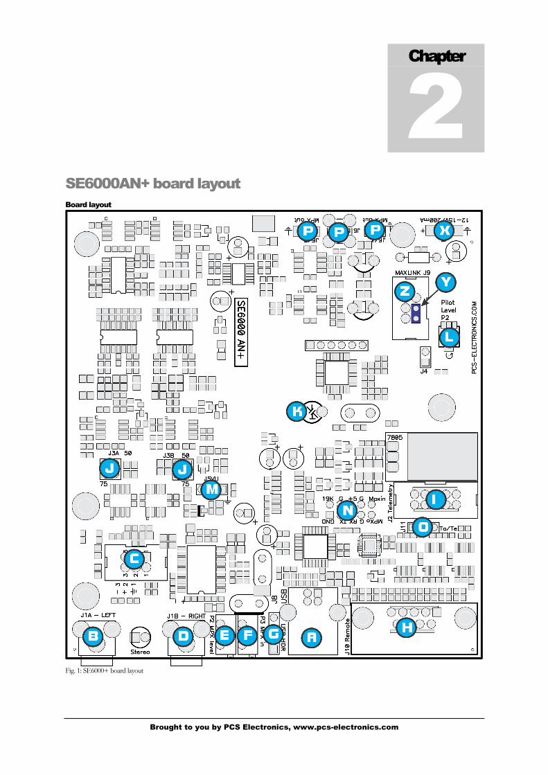
Balanced audio and power connector
SE6000 AN+ features balanced audio inputs, just connect XLR connector to L or R 3-pin headers (close to rca jacks). Pin 1
is ground, the other two are Audio + and Audio -. They are numbered 1-3 and match the markings on the connector, so just
make sure you are connecting 1 to pin 1, 2 to pin 2 etc. Any hum problems usually magically disappear once the XLR input
is used instead of the basic unbalanced RCA input. Note that you will have to purchase XLR connectors as only RCA type is
provided on the PCB. These inputs are DC coupled and are sensitive to large DC or mains voltages, make sure all
equipment is grounded to the same potential before connecting cables.
Fig. 4: Balanced audio input – Panel mounted XLR connector
Chapter
4

Brought to you by PCS Electronics, www.pcs-electronics.com
Digital audio streaming
If you want to drive your audio digitally, connect USB cable to the USB port on the computer and the stereo encoder. Your
PC will detect the sound interface automatically. You can now play your audio digitally. In your media player look under
options and make sure you output your audio to the “USB audio adapter”. Whatever you play will be heard via your FM
transmitter.
Stereo/mono mode selection and maxlink connector
Stereo/mono mode selection is now possible in 2 different ways:
You can install or remove jumper Y to get MONO/STEREO mode
When using together with our FM exciters just connect the MAXLINK flat cable to the SE6000+ and MAX PRO
2000/3000/5000 serues RF board; you can now set the mode via LCD control module/menu system from your FM exciter.
Brought to you by PCS Electronics, www.pcs-electronics.com
Setup and testing
Setting up levels
Let’s assume that you don’t own an expensive peak deviation meter or modulation meter/analyzers. If you have or can gain
access to these pieces of equipment then you probably also know how to use them; setting of the level is as easy as adjusting
the input level of the transmitter for the appropriate deviation.
SE6000+ is very easy to setup. What we do have to do however is match the output level of the encoder and input level of
the transmitter so that the pilot tone (19 kHz) alone (no audio) gives a deviation of the exciter of 6.75 kHz (9 percent). This
automatically sets the remaining audio levels. If you’re using our line of FM exciters just connect the stereo encoder to the
transmitter, set encoder to Stereo, set audio level on the fm transmitter to zero and keep increasing it until the stereo led on
the receiver comes on and go a bit above that point.
If needed, it is also possible to adjust stereo pilot level with a trimmer (L).
DO NOT FORGET TO DISABLE PREEMPHASIS AT THE TRANSMITTER WHEN YOU CONNECT IT TO
THE STEREO ENCODER (failure to do so results in very poor stereo separation and distortion).
Chapter
5

Brought to you by PCS Electronics, www.pcs-electronics.com
Troubleshooting
Troubleshooting
We hope you’ll never get to this step. We all know bad things happen but do not despair! There is some basic polarity
protection, the 1ohm thru-hole resistor closer to supply power connector is the first thing to check. Also make sure
microphone/shielded audio cable leading from MPX output to the transmitter is not shorted. Next check the
troubleshooting table on the next page. If you have problems you cannot solve yourself, please see our website for contact
information and support resources in our forum.
Fig 5: So, do you think you can handle it? We think you sure can!
Chapter
7

Brought to you by PCS Electronics, www.pcs-electronics.com
PROBLEM DESCRIPTION POSSIBLE SOLUTIONS
Mono operation only, no stereo 1. Check supply power and voltage
2. Did you connect Maxlink to LCD and set operation to mono with your LCD
module? You can only use one method to select stereo/mono mode
3. Is the MONO/STEREO jumper in correct position, is the stereo LED on?
4. Increase audio level in the FM exciter a little bit
5. You may need to increase pilot level a little with P2
Very poor stereo separation,
strange audio
1. Make sure you disable pre-emphasis in your FM EXCITER. Check supply voltage
Audio without any treble Set pre-emphasis on the stereo encoder board (either 50uS or 75uS).
Audio too quiet Increase level on your audio source a little bit
There is HUM in audio - Try with a different mains power supply.
- Move antenna as far away from the transmitter and audio gear as possible
- Use XLR audio connectors or digital audio, if possible (USB)
- Make sure SWR is low
- Keep audio cables short and away from antenna and RF coaxial cable
- Form a coil from coaxial cable going to the antenna, make a few turns. This stops
RF currents that might be flowing on the outer braid of the coaxial cable. This
usually happens when you connect unbalanced cable to balanced antenna without
proper BALUN (balanced-unbalanced convertor) resulting in coaxial cable
becoming part of the antenna and radiating RF energy as well…causing hum.

Brought to you by PCS Electronics, www.pcs-electronics.com
Appendix A: Connecting stereo encoder to MAXPRO FM
exciter
Using our stereo encoders together with our MAX PRO FM exciters is a great idea as you can control all parameters through
the same LCD unit used for FM exciter. Since the introduction of the new MaxLink interconnect system this is really easy to
do, you do not have to fiddle with wires and soldering iron anymore. The MaxLinkTM is a 6-wire flat cable interconnect
system that is simply plugged into appropriate connector on the stereo encoder board and the other end into connector on
FM exciter board. See fig. 19 below for wiring directions. You don’t even have to wire a separate supply (12V) wire to the
stereo encoder as the MaxLink cable delivers supply voltage as well. You still have to connect audio cable (MPX out to audio
input of the FM exciter), but that is really easy to do. It is best to use shielded microphone cable.
Remember to set the following:
Remove the STEREO/MONO jumper as this is now controlled via FM exciter’s LCD module. If stereo mode LED is
illuminated, you are in STEREO mode.
Disable pre-emphasis in the MAX PRO 3000+ exciter board (jumper in position “None”). Pre-emphasis is now handled by
stereo encoder(se5000 or other), you can set it there either to 50uS or 75uS.
Set the audio level (P1) on MAX PRO 3000+ so that the stereo indicator on the radio just turns on, than increase it slightly
more (make sure you are in stereo mode when you do this alignment).
Fig. 6: Connecting stereo encoder to FM exciter.
Appendix
A

Brought to you by PCS Electronics, www.pcs-electronics.com
Appendix B: Connecting VUMAX-1
How about adding some flashing lights to your transmitter? It is much easier than you think. Fortunately we provided for
VU meter, look for the 5-pin header (marked with N). You can connect our VU MAX I vu meter module to this header.
Just be sure to orient the cable correctly. The square pin (ground) should be aligned on both sides. The remaining 3-pin
header on the VU-MAX1 vu meter board can be connected to stereo encoder (SE5000 or SE2000/SE3000). This way you
get the 40 LEDs on the VU MAX board flash according to the power, swr and audio volume (left and right channel
separately). Maxlink cable between exciter and SE2000/SE3000 is not shown for simplicity. The block diagram is below:
Fig. 20: Connecting VU meter to FM exciter
Fig. 21: VU MAX-1
Note: Sometimes (depending on case design) RF energy from transmitter interferes with VU meter operation. A typical sign
of the problem would be 1-2 LEDs for audio constantly illuminated. If you experience this problem place two capacitors
(100pF) on the VU MAX-1 PCB board, at the 3-pin jumper shown above. One capacitor goes from pin 2 to pin 1, the other
goes from pin 3 to pin 1. This way you ground these two audio inputs for RF signal and the problem goes away.
Appendix
B

Brought to you by PCS Electronics, www.pcs-electronics.com
Appendix C: Complete FM transmitter block by block
Now that you’ve connected stereo encoder and already have nice stereo sound, it may be time to increase your power
output. How about adding an external amplifier? Some of you will say, sure, but will the nice power/swr meter built into
MAX PRO 3000+ know how to measure power with this amplifier added and will it show it properly on the LCD display?
The good news is that we have a solution for this. Not only does the MAX PRO 3000+ have ability to read power/swr with
external amplifier installed, it can also read amplifier temperature and amplifier supply voltage. To top this off, swr and
temperature protection still works just like before.
Fig. 22: Connecting an external amplifier module – Complete FM transmitter, block diagram
Diagram above explains the entire FM transmitter system, with mains power supply (1), DCDC converter (2), stereo
encoder (3), FM exciter (4), FM amplifier pallet (5), output filter (6), ControlMini board (7), interconnect system (8 &9) and
cooling fans. I will briefly explain each of the above subsystems:
1.) MAINS POWER SUPPLY: Provides power for the entire transmitter. Usually accepts mains voltage, from 110 to 240V,
and outputs 24 or 48V DC. Exact power rating depends on the power consumption of the entire transmitter. A 300W
transmitter usually consumes around 500W of power. A 1000W transmitter typically consumes around 1500W of power. An
engineer should also consider safety margin and use a power supply that can provide slightly more power than needed.
Voltage rating for mains power supply depends primarily on the type of amplifier used. Most pallets accept 24-28 or 48-50V.
You can find all kinds of mains power supplies here at our website:
http://www.pcs-electronics.com/transmitter-accesories-mains-power-supply-c-71_74.html
Appendix
C

Brought to you by PCS Electronics, www.pcs-electronics.com
2.) Stereo encoders and FM exciters typically operate from 12V DC stabilized voltage. Since at the moment we only have 24
or 48V inside our system shown in diagram above and we don’t want to use another big 110-240V/12V mains power supply
we are going to use own small DCDC converter. This conveniently converts any voltage from 17-50V down into 12-15V.
Exact voltage can be adjusted with a trimmer. Another convenient bonus point for this tiny DC/DC converter is that it also
provides power for fans (10). And you will need fans to cool the exciter, mains power supply and amplifier. Moreover, you
can set temperature at which the fans start working or you can have fans work continuously.
You can find our DCDC converter with fan controller here at our website:
http://www.pcs-electronics.com/2048v-dcdc-converter-p-1549.html
3.) Stereo encoders, we covered this in detail above. You can find our stereo encoders here:
http://www.pcs-electronics.com/stereo-encoders-c-36.html
4.) Our FM exciters, at the moment MAX PRO 3000+ and MAX PRO 4025 support all the mentioned functions. Make
sure to limit the maximum output power of the exciter in order not to damage the amplifier. The procedure is described
in Chapter 7 of this manful. By limiting the maximum output power the LCD module still works, but its adjustment range is
decreased to go from 0 to 2W for example or from 0 to 4W. Another very important advice is to use an attenuator between
exciter and amplifier. Amplifiers almost always have input impedance that does not match 50 ohms across the entire FM
band. By using 1-3dB attenuator this can be brought closer to 50 ohms. Our attenuators are available here, but you can also
construct your own from regular resistors, you can contact us for a schematic diagram:
http://www.pcs-electronics.com/mounted-attenuators-p-1105.html
BEFORE CONNECTING AMPLIFIER ALWAYS MAKE SURE THAT EXCITER OUTPUT POWER DOES NOT EXCEED MAXIMUM ALLOWABLE INPUT POWER OF THE AMPLIFIER!
LIMIT MAXIMUM OUTPUT POWER OF THE EXCITER, PROCEDURE IS DESCRIBED IN CHAPTER 7 IN THIS MANUAL!
5.) FM amplifier. This is typically a pallet amplifier such as any of these on our website, they all come with ControlMini2
included. Also make sure to include a heatsink with pallets as they require one. It is often a good idea to insert a small
attenuator between exciter and amplifier.
http://www.pcs-electronics.com/amplifiers-pallet-amplifiers-c-41_109.html
You can also use any of these here, these already contain filters and heatsink so your work is easier:
http://www.pcs-electronics.com/amplifiers-complete-amplifier-modules-c-41_111.html
Amplifiers can have input impedance that does not match 50 ohms across the entire FM band. By using 1-3dB attenuator
this can be brought closer to 50 ohms. Our attenuators are available here, but you can also construct your own:
http://www.pcs-electronics.com/mounted-attenuators-p-1105.html
6.) Low pass filter for FM band. You can use any of these here, but make sure they are strong enough to handle the power
level of the amplifier (note that complete amplifiers with heatsink and low pass filter do not require extra filter):
http://www.pcs-electronics.com/transmitter-accesories-filters-transmitters-c-71_73.html
7.) ControlMini2 board. This board is connected to the MAX PRO 3000+ via flat cable (8 – DIGAMP-10). It makes it
possible for MAX PRO 3000+ to read POWER and SWR of the amplifier module. There is also a solder post for
temperature sensor and amplifier supply voltage. The board contains directional couplers for power and swr, SWR
protection and ALC system. For better description look at the next appendix. We are now shipping these boards and 10 cm
long flat cable with all our FM amplifiers (pallets and complete amplifier modules). This board can take about 500-750W of
power maximum. However, when used with complete amplifier modules you can use them up to 2KW of RF power.

Brought to you by PCS Electronics, www.pcs-electronics.com
8.) MAXLINK flat cable connects stereo encoder with the FM exciter, it enables control and supplies 12-15V DC for the
stereo encoder. You can purchase this cable along with stereo encoder here:
http://www.pcs-electronics.com/se5000-stereo-encoder-p-1274.html
9.) DIGAMP-10 flat cable connects MAX PRO 3000+ FM exciter with ControlMini2, it makes it possible for MAX PRO
3000+ to read power, swr, temperature and voltage of the amplifier module, you receive this cable along with ControlMini2
whenever you buy any of our pallets or complete FM amplifier modules:
http://www.pcs-electronics.com/fm-amplifiers-c-41.html
10.) Fans are very important, they ensure proper cooling of your amplifier, mains power supply and exciter. Usual fans that
you can buy in local shops are often not strong enough and can fail far too soon. We carry a line of professional fans with
higher reliability and very high airflow, you can order them here:
http://www.pcs-electronics.com/amplifiers-amplifier-accesories-c-41_112.html
11.) You will need to place all these items in a nice enclosure. Aluminum works well and is not too heavy. Keeping it
conductive is an advantage (most types of anodizing make aluminum’s surface non-conductive). We carry a line of
professional rack enclosures, designed so that the above mentioned items fit perfectly. Now you can build your FM
transmitter yourself, all the way up to 2000W:
http://www.pcs-electronics.com/rack-cabinets-boxes-c-93.html
Finally, we recommend that you use Teflon coaxial cable for all internal coaxial connections. The reason is primarily that
Teflon does not melt while soldering or use. You can be sure no short will form between the center and shield, either
immediately at soldering or with time, if the cable is under a lot of thermal stress (coax can warm up nicely already in a 300W
transmitter). Insulation in RG58 or similar lossy cheap coaxial cables can literally melt and cause a short between the center
and shield already at moderate power levels around 300W. You can buy suitable Teflon coaxial cable here (I suggest RG188
for low power and RG142, RG316, R303 for higher power levels):
http://www.pcs-electronics.com/semirigid-25ohm-other-special-coaxial-cable-p-1275.html

Brought to you by PCS Electronics, www.pcs-electronics.com
Appendix D: General tips for setting up transmitters
Typical FM transmitter setups
Below are several of the typical broadcasting systems that can be encountered worldwide.
Fig. 25: Typical broadcasting systems
Lets look at system A first. It consists of audio source (mixer, microphones, CD players and a PC), FM exciter with
integrated RDS and stereo encoder (such as our CyberMaxFM+ units from 15W-300W) and antenna. Note antenna in this
system is located in the same location as the transmitter and studio, typically it would be placed on a small tower or a pole at
the top of the building with studio. Disadvantage of this system is that you have to keep studio, transmitter and antenna
close. Now you usually can’t place studio on the top of a mountain for practical reasons so this limits your range. This is a
typical small community radio with output powers of up to 300-500W.
System B is very similar to system A, but operators have decided to add an additional amplifier to boost the range. Such
stations can go into kilowatts, but they are starting to hit another speed limit. Since the studio is typically located in a town,
high RF powers aren’t desirable due to interference with other services and safety regulations. So range is still limited
compared to system C stations.
System C is radically different in one respect. Antenna and transmitter are no longer located at the same place with the
studio. To accomplish this the two audio channels are first combined with stereo processor. Resulting MPX signal is than
passed to the STL wireless link transmitter (STL=Studio Transmitter Link). Up in the mountains is a STL wireless link
receiver that receives the signal from the studio and passes I to the exciter. In this case exciter does not need to be stereo
anymore since composite MPX signal is passed to its MPX input (all mono transmitters have this input). Such exciters can
than optionally drive big amplifiers with powers going into tens of KW with maximum range.
You can check our amplifiers here: http://www.pcs-electronics.com/fm-amplifiers-c-41.html
You can check our wireless STL links here: http://www.pcs-electronics.com/wireless-audio-links-c-42.html
Appendix
D

Brought to you by PCS Electronics, www.pcs-electronics.com
Typical FM broadcasting antenna setups
Below are several of the typical broadcasting antenna systems that can be encountered worldwide.
Fig. 26: Typical antenna setups
Lets look at system A first. It’s a simple vertical dipole antenna, mounted on a pole. The gain of this antenna is 0dBd and if
we assume that the coaxial cable does not have any losses the ERP of this system equals transmitter power. For example, a
1KW transmitter with this antenna system and perfect coaxial cable (losses=0) would have ERP of 1000W. Radiation
pattern of this system is more-less omni-directional but since the metal pole holding the antenna blocks the signal there is a
null of signal exactly on the opposite side of the pole.
System B has two simple dipole antennas mounted on a pole. The gain of this antenna is slightly less than 3dBd (due to
losses in harness – splitter). If we assume that the coaxial cable does not have any losses the ERP of this system equals
double transmitter power. For example, a 1KW transmitter with this antenna system and perfect coaxial cable (losses=0)
would have ERP of 2000W. Note the antennas are mounted on the opposite sides of the pole to help make radiation pattern
as omni-directional as possible.
System C has four simple vertical dipole antennas mounted on a pole. One of the antennas is behind the pole and is not
visible. Note the antennas are mounted at an angle of 90 degrees between each other to help make radiation pattern as omni-
directional as possible. The gain of this antenna is slightly less than 6dBd (due to losses in harness – splitter). If we assume
that the coaxial cable does not have any losses the ERP of this system equals 4x transmitter power. For example, a 1KW
transmitter with this antenna system and perfect coaxial cable (losses=0) would have ERP of 4000W.
System C has theoretically double the range of the System A although in practice it takes 4-6x increase of power to double
the range. 4x increase of power is equal to 6dB of gain. And you get 3dB of gain by doubling the number of dipoles. So to
upgrade system C to 9dBd you’d need 8 dipoles. And for 12dBd you’d need 16 dipoles. 16 dipoles would in theory increase
your range 4x compared to a single dipole. In practice there would be some losses in combining so many dipoles. You can
use circular dipoles in very similar configurations.

Brought to you by PCS Electronics, www.pcs-electronics.com
Wiring antennas in multi-bay configurations
We have observed typical multi-dipole (called multi-bay) antenna configurations on the previous page. However there are
some things to keep in mind.
Fig. 27: Wiring multi-bay antennas
Look at the diagram above. This is a simple system with two dipole antennas and a 2-way coaxial splitter (harness). This
splitter is made from sections of coaxial cable with such impedance and length which ensure perfect match at specific
frequency. Do not attempt to assemble from regular 50-ohm coaxial cable. What is important here is that the two sections of
coaxial cable going from antenna to the splitter should be of exact equal length. These two sections are shown in black. The
same rule applies for system with more dipoles. It is also possible to have cables of different lengths, but you have to know
velocity factor of the cable so we have omitted this for simplicity reasons. If you want more info please contact our technical
staff.
Brought to you by PCS Electronics, www.pcs-electronics.com
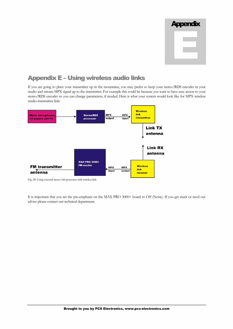
Appendix E – Using wireless audio links
If you are going to place your transmitter up in the mountains, you may prefer to keep your stereo/RDS encoder in your
studio and stream MPX signal up to the transmitter. For example this could be because you want to have easy access to your
stereo/RDS encoder so you can change parameters, if needed. Here is what your system would look like for MPX wireless
studio-transmitter link:
Fig. 28: Using external stereo/rds processor with wireless link
It is important that you set the pre-emphasis on the MAX PRO 3000+ board to Off (None). If you get stuck or need our
advice please contact our technical department.
Appendix
E

Brought to you by PCS Electronics, www.pcs-electronics.com
Appendix F – Warranty and legal info
Important notice!
Please remember to turn off the transmitter/amplifier when not in use! This goes especially for high powered
transmitters. Remember that anything you broadcast through the transmitter can be heard by anyone tuning in to that
frequency. Although it is unlikely certain weather conditions may allow the signal to go further than your immediate
listening area so please don't broadcast anything you don't mind anyone else hearing.
Warranty and servicing!
Within one (1) year of receiving your order, if any product proves to be defective; please contact us via e-mail or our
feedback form. Please DO NOT ship the product back to us without contacting us first and receiving return instructions.
After we receive the defective merchandise, we will test it if need be, and we will ship back to you a non-defective
replacement product. Please note that this doesn't cover final RF transistor as it can be damaged by using defective or
poorly matched antenna. An exception is as well any mishandling or abuse by the customer. If the product is defective, you
will receive a replacement. If you choose to return the defective item, rather than replace it, we will charge a 20% restocking
fee and your original shipping and handling charges will not be refunded. The return of the product is at your expense. We
believe that this is a fair policy because lower overhead results in lower prices for all of our customers.
Legal info
It may be illegal to operate this device in your county. Please consult local authorities before using our products! PCS
Elektronik d.o.o. is not responsible for any damage to your PC arising from use of this product and will not be held
responsible for any violation of local laws pertaining to the use of this product. It is entirely your responsibility that you
make sure you operate in accordance with local laws and/or regulations.
Limitation of liability
To the law, in no event shall PCS Elektronik d.o.o. or its suppliers be liable for any special, incidental, indirect, or
consequential damages whatsoever (including, without limitation, damages for loss of business profits, business interruption,
loss of business information, or any other pecuniary loss) arising out of the use of or inability to use the PRODUCT, even if
PCS Elektronik d.o.o. has been advised of the possibility of such damages. In any case, PCS Elektronik d.o.o.´s entire
liability under any provision of this agreement shall be limited to the greater of the amount actually paid by you for the
PRODUCT or U.S. $5.00; because some states and jurisdictions do not allow the exclusion or limitation of liability, the
above limitation may not apply to you.
Appendix
F

Brought to you by PCS Electronics, www.pcs-electronics.com
Also available from www.pcs-electronics.com
We also carry a big range of:
- FM transmitters in assembled and KIT form
- TV transmitters in assembled and KIT form, VHF and UHF
- AM transmitters with extremely clear modulation (PWM design)
- Various accessories for professional and hobby FM radio stations
- A large assortment of hard to obtain RF components (RF transistors; MRF, 2SC, coils, silver plated wire, coaxial cable, capacitors, quartz crystals and many others)
- PC based FM transmitters (PCI MAX pc based FM transmitter turns your PC into a radio station)
- A large number of beginners guides to get you started
- A large selection of free schematics is as well available at our website.
If you can’t get much range with your homebrew antenna, have a look at these: http://www.pcs-electronics.com

Brought to you by PCS Electronics, www.pcs-electronics.com
Revisions and errata
V1.0 (March,2012): Release version
Please report any errors you see in this manual, you will be helping us and many other users out there. Thank you!

25
Index
board layout, 3
drill template, 5
mains cable, 8
mains power supply, 8
Technical specifications, 2
Troubleshooting, 11
![Copyright c 2007 Pegasys Inc,All rights reserved. · Linear PCM Dolby Digital [Mono/Stereo] PEGASYS Dolby Digital Encoder SDK Encoder DATA DATA DATA Dolby](https://img.pdfslide.us/doc/110x75/5d676a0d88c993d5408b7516/copyright-c-2007-pegasys-incall-rights-linear-pcm-dolby-digital-monostereo.jpg)