Embed Size (px)
Citation preview

MANUAL
Application notes for safety-instrumented systems
Competence in Functional Safety
Application notes for safety-instrumented systems
2
Application notes for safety-instrumented systems
3
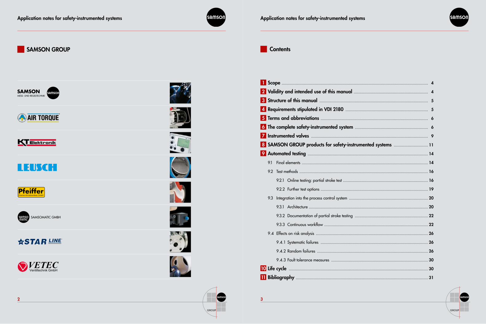
SAMSON GROUP Contents
Scope ............................................................................................................................ 4
Validity and intended use of this manual ............................................................... 4
Structure of this manual ............................................................................................ 5
Requirements stipulated in VDI 2180 ...................................................................... 5 Terms and abbreviations ........................................................................................... 6
The complete safety-instrumented system .............................................................. 6 Instrumented valves ................................................................................................... 9
SAMSON GROUP products for safety-instrumented systems ............................. 11
Automated testing ...................................................................................................... 14
9.1 Final elements ........................................................................................................... 14
9.2 Test methods ............................................................................................................. 16
9.2.1 Online testing: partial stroke test ........................................................................ 16
9.2.2 Further test options ........................................................................................... 19
9.3 Integration into the process control system ................................................................... 20
9.3.1 Architecture ..................................................................................................... 20
9.3.2 Documentation of partial stroke testing .............................................................. 22
9.3.3 Continuous workflow ........................................................................................ 22
9.4 Effects on risk analysis ............................................................................................... 26
9.4.1 Systematic failures ........................................................................................... 26
9.4.2 Random failures .............................................................................................. 26
9.4.3 Fault tolerance measures .................................................................................. 30
Life cycle ...................................................................................................................... 30
Bibliography ................................................................................................................ 31
3
4
5
6
7
8
10
9
11
2
1
Application notes for safety-instrumented systems
4
Application notes for safety-instrumented systems
5
1 Scope
Safety-instrumented systems serve to protect process engineering plants. One process variable, e.g. pressure or temperature, is monitored by a sensor to ensure it does not exceed a certain limit. If the variable exceeds or falls below the limit, a safety PLC (Programmable Logic Controller) controls a valve, which shuts off or opens the pipe-line accordingly.These control valves are automated by pneumatic actuators controlled by solenoid valves. Some of them are equipped to feed back the end positions. It is state of the art to also use positioners. They perform diagnostic functions on the valve while a process is running, but they can also assume the solenoid valve’s shutdown func-tion. IEC 61511 and VDI 2180 stipulate that plants need to be subjected to recurrent tests to detect whether they function safely on demand. In addition, tests can be performed while a process is running. This manual provides information on automating these tests concerning:
Components and setup��
Test performance��
Connection to the process control system or safety PLC��
Interpretation of test results according to IEC 61511 and VDI 2180��
2 Validity and intended use of this manual
This manual is intended to enable planners and plant operators to implement state-of-the-art methods of testing control valves.The examples and proposed equipment setups refer to selected instruments provided by SAMSON AG. Observe the intended use of these instruments as specified in the associated data sheets as well as the mounting and op-erating instructions. Also refer to the Competence in Functional Safety – Functional safety of globe valves, rotary plug valves, ball valves and butterfly valves manual (WA 236) published by SAMSON AG.It is the responsibility of plant operators to draw up a risk analysis and specifications for the safety-instrumented systems in their specific plants. Requirements applying to the control valves used in safety-instrumented systems as well as to testing these valves can be derived from them.
3 Structure of this manual
We will start by introducing the requirements stipulated in the VDI 2180 standard. In the following, we will de-scribe a simple example of a safety-instrumented system (SIS). Also, we will deal with possible configurations of the valve and mounted valve accessories used in the safety-instrumented system. Finally, we will discuss state-of-the-art test methods. We will look at the following aspects:
Possible test procedures��
Integration into the higher-level process control system��
Effects on safety assessment��
4 Requirements stipulated in VDI 2180
In Part 5 of VDI 2180, practical recommendations are given for engineering, implementation and operation of safety-instrumented systems. The main claim is that safety installations must be robust against failures. As a result, measures need to be taken:
Against systematic failures��
Against random failures��
To improve fault tolerance��
In section 3.1 of VDI 2180, Part 5, it is demanded that all three measures always be taken for each safety-instru-mented system. It is recommended to use instruments proven-in-use (refer to NAMUR Recommendation NE 130), in particular to ensure that the instrument is suitable for the selected industrial process.Recurrent functional tests are to be performed, documenting the test results. Performing and documenting these functional tests can be automated. The proof test to demonstrate that the safety-instrumented system itself is free of faults is performed while the plant is shut down. In addition, tests can be performed while the process is running (online tests). Diagnostic coverage (DC) is spe-cific to the selected method and instruments used. Furthermore, the safety-instrumented system can be assessed based on spurious trips.
Application notes for safety-instrumented systems
6
Application notes for safety-instrumented systems
7
5 Terms and abbreviations
Also see SAMSON manual WA 236The following terms and abbreviations are used in addition:
Term Abbreviation
Basic process control system BPCS
Diagnostic coverage DC
Probability of failure on demand PFD
Safety integrity level SIL
Safety programmable logic controller Safety PLC
Safety-instrumented system SIS
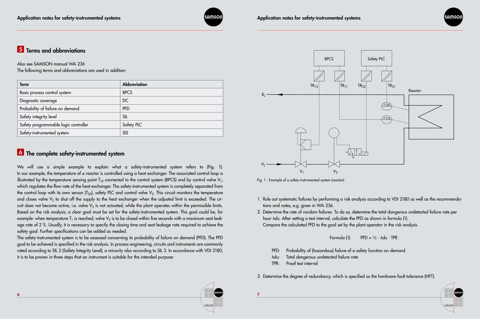
6 The complete safety-instrumented system
We will use a simple example to explain what a safety-instrumented system refers to (Fig. 1). In our example, the temperature of a reactor is controlled using a heat exchanger. The associated control loop is illustrated by the temperature sensing point T10 connected to the control system (BPCS) and by control valve V1, which regulates the flow rate of the heat exchanger. The safety-instrumented system is completely separated from the control loop with its own sensor (T20), safety PLC and control valve V2. This circuit monitors the temperature and closes valve V2 to shut off the supply to the heat exchanger when the adjusted limit is exceeded. The cir-cuit does not become active, i.e. valve V2 is not actuated, while the plant operates within the permissible limits. Based on the risk analysis, a clear goal must be set for the safety-instrumented system. This goal could be, for example: when temperature T1 is reached, valve V2 is to be closed within five seconds with a maximum seat leak-age rate of 2 %. Usually, it is necessary to specify the closing time and seat leakage rate required to achieve the safety goal. Further specifications can be added as needed.The safety-instrumented system is to be assessed concerning its probability of failure on demand (PFD). The PFD goal to be achieved is specified in the risk analysis. In process engineering, circuits and instruments are commonly rated according to SIL 2 (Safety Integrity Level), a minority also according to SIL 3. In accordance with VDI 2180, it is to be proven in three steps that an instrument is suitable for the intended purpose:
BPCS
TR11TR12 TR21
T T20
V2V1
TR22
Safety PLC
ReactorRL
VL
T T10
Fig. 1 · Example of a safety-instrumented system (reactor)
Rule out systematic failures by performing a risk analysis according to VDI 2180 as well as the recommenda-1. tions and notes, e.g. given in WA 236.Determine the rate of random failures. To do so, determine the total dangerous undetected failure rate per 2. hour λdu. After setting a test interval, calculate the PFD as shown in formula (1). Compare the calculated PFD to the goal set by the plant operator in the risk analysis. Formula (1) PFD = ½ · λdu · TPR PFD: Probability of (hazardous) failure of a safety function on demand λdu: Total dangerous undetected failure rate TPR: Proof test interval
Determine the degree of redundancy, which is specified as the hardware fault tolerance (HFT).3.
Application notes for safety-instrumented systems
8
Application notes for safety-instrumented systems
9
T20 TR21 Safety PLC TR22 V2 Σ
237 FIT 77 FIT 45 FIT 77 FIT 103 FIT 539 FIT
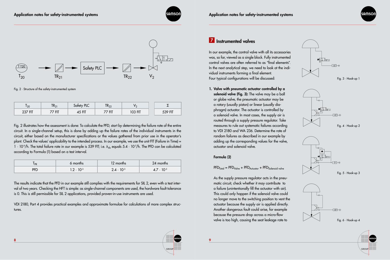
Fig. 2 illustrates how the assessment is done: To calculate the PFD, start by determining the failure rate of the entire circuit. In a single-channel setup, this is done by adding up the failure rates of the individual instruments in the circuit, either based on the manufacturer specifications or the values gathered from prior use in the operator‘s plant. Check the values‘ applicability to the intended process. In our example, we use the unit FIT (Failure in Time) = 1 · 10-9/h. The total failure rate in our example is 539 FIT; i.e. λdu equals 5.4 · 10-7/h. The PFD can be calculated according to Formula (1) based on a test interval.
TPR 6 months 12 months 24 months
PFD 1.2 · 10-3 2.4 · 10-3 4.7 · 10-3
The results indicate that the PFD in our example still complies with the requirements for SIL 2, even with a test inter-val of two years. Checking the HFT is simple: as single-channel components are used, the hardware fault tolerance is 0. This is still permissible for SIL 2 applications, provided proven-in-use instruments are used.
VDI 2180, Part 4 provides practical examples and approximate formulae for calculations of more complex struc-tures.
7 Instrumented valves
In our example, the control valve with all its accessories was, so far, viewed as a single block. Fully instrumented control valves are often referred to as “final elements”. In the next analytical step, we need to look at the indi-vidual instruments forming a final element.Four typical configurations will be discussed:
Valve with pneumatic actuator controlled by a 1. solenoid valve (Fig. 3): The valve may be a ball or globe valve, the pneumatic actuator may be a rotary (usually piston) or linear (usually dia-phragm) actuator. The actuator is controlled by a solenoid valve. In most cases, the supply air is routed through a supply pressure regulator. Take measures to rule out systematic failures according to VDI 2180 and WA 236. Determine the rate of random failures as described in our example by adding up the corresponding values for the valve, actuator and solenoid valve. Formula (2) PFDTotal = PFDValve + PFDActuator + PFDSolenoid valve As the supply pressure regulator acts in the pneu-matic circuit, check whether it may contribute to a failure (unintentionally fill the actuator with air). This could only happen if the solenoid valve could no longer move to the switching position to vent the actuator because the supply air is applied directly. Another dangerous fault could arise, for example because the pressure drop across a micro-flow valve is too high, causing the seat leakage rate to
V2TR22T20 TR21
Safety PLCT T20
Fig. 2 · Structure of the safety-instrumented system
Fig. 3 · Hook-up 1
Fig. 4 · Hook-up 2
Fig. 5 · Hook-up 3
Fig. 6 · Hook-up 4
Application notes for safety-instrumented systems
10
Application notes for safety-instrumented systems
11
increase. In general, it can be said that failures caused by the supply pressure regulator can be ruled out. Frequently, limit switches are used. However, they only need to be considered in the risk analysis if several control valves need to be moved to their fail-safe positions in series. Valve, actuator, solenoid valve and positioner: 2. If positioners are also used for emergency shutdown, the hook-up is as shown in Fig. 4. Alternatively, such a configuration can be used on on/off valves to perform online tests while the process is running. An important online test is the partial stroke test (PST). To determine the safety properties, assess the instruments required for emergency shutdown. In our example, these are the valve, actuator and solenoid valve. The function of the positioner is important for the availability of the configuration in the plant but does not play any role in emergency shutdown. Perform the assessment as described in example 1.Valve, actuator, solenoid valve, positioner and booster:3. A booster may be needed to achieve certain set-tling and closing times. Fig. 5 shows a sample configuration. In the example, the booster is mounted be-tween the solenoid valve and actuator. This is necessary if the solenoid valve’s air capacity is not sufficient to achieve the required closing time. In this configuration, the booster is part of the safety-instrumented system. As a result, it needs to be assessed concerning systematic and random failures in addition to the instruments mentioned in example 1.Valve, actuator and positioner:4. A simple, yet state-of-the-art configuration is shown in Fig. 6. In the exam-ple, a positioner instead of a solenoid valve is used for emergency shutdown. This is possible with positioners, such as SAMSON’s Type 3730-3, whose emergency shutdown is proven by a manufacturer declaration or certification by an independent expert body. In this positioner, shutdown is performed at a signal of either 3.8 mA or 0 mA. In the configuration, the positioner can also be used for diagnostics and testing, such as PST. Configuring the positioner to shut down at 3.8 mA brings the added benefit that the valve’s travel through its full range to the end position can be traced, recorded and analyzed for diagnostic purposes. As a result, the proof test or spurious trips can be documented and assessed.
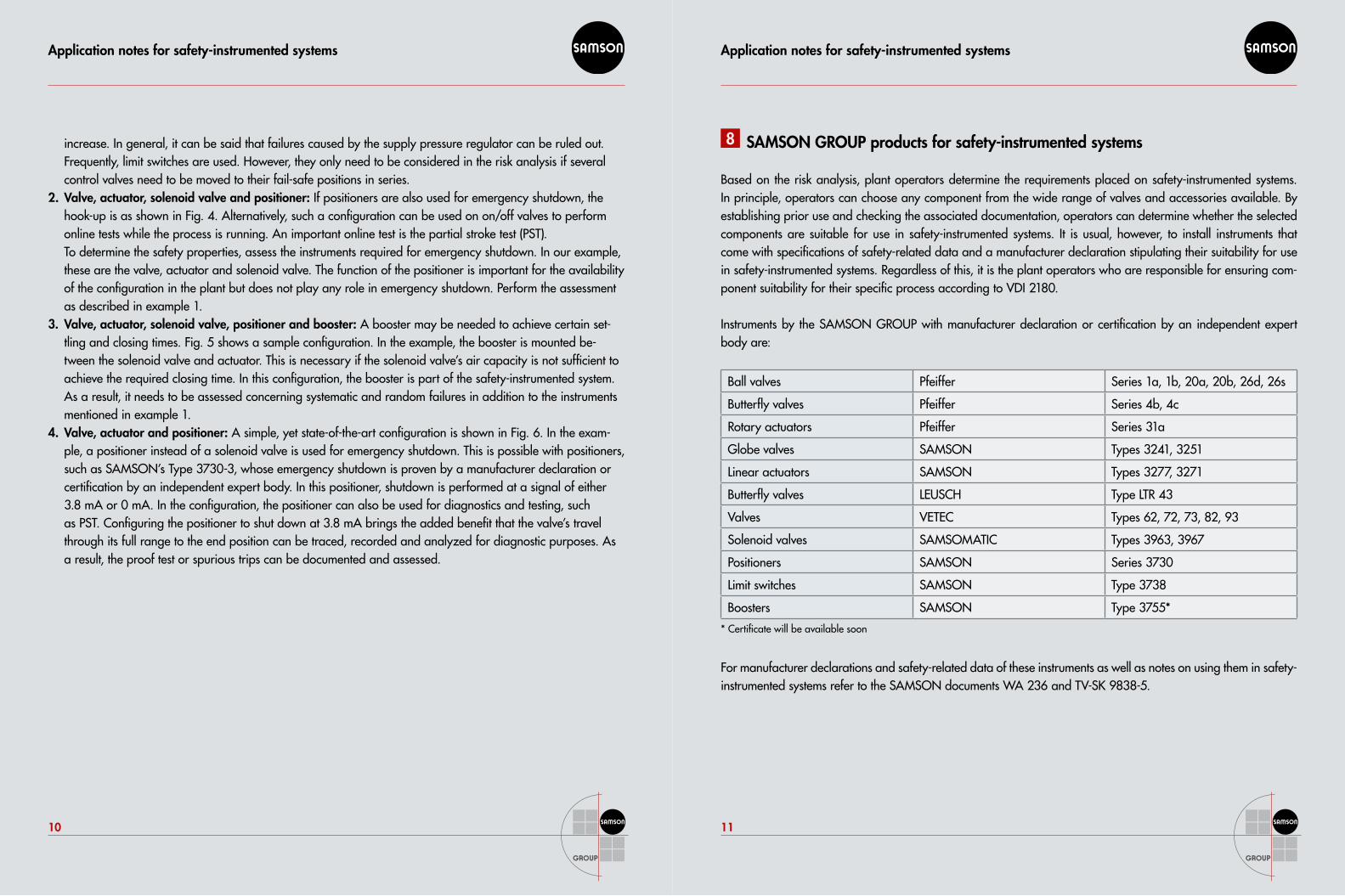
8 SAMSON GROUP products for safety-instrumented systems
Based on the risk analysis, plant operators determine the requirements placed on safety-instrumented systems. In principle, operators can choose any component from the wide range of valves and accessories available. By establishing prior use and checking the associated documentation, operators can determine whether the selected components are suitable for use in safety-instrumented systems. It is usual, however, to install instruments that come with specifications of safety-related data and a manufacturer declaration stipulating their suitability for use in safety-instrumented systems. Regardless of this, it is the plant operators who are responsible for ensuring com-ponent suitability for their specific process according to VDI 2180.
Instruments by the SAMSON GROUP with manufacturer declaration or certification by an independent expert body are:
Ball valves Pfeiffer Series 1a, 1b, 20a, 20b, 26d, 26s
Butterfly valves Pfeiffer Series 4b, 4c
Rotary actuators Pfeiffer Series 31a
Globe valves SAMSON Types 3241, 3251
Linear actuators SAMSON Types 3277, 3271
Butterfly valves LEUSCH Type LTR 43
Valves VETEC Types 62, 72, 73, 82, 93
Solenoid valves SAMSOMATIC Types 3963, 3967
Positioners SAMSON Series 3730
Limit switches SAMSON Type 3738
Boosters SAMSON Type 3755*
* Certificate will be available soon
For manufacturer declarations and safety-related data of these instruments as well as notes on using them in safety-instrumented systems refer to the SAMSON documents WA 236 and TV-SK 9838-5.
Application notes for safety-instrumented systems
12
Application notes for safety-instrumented systems
13
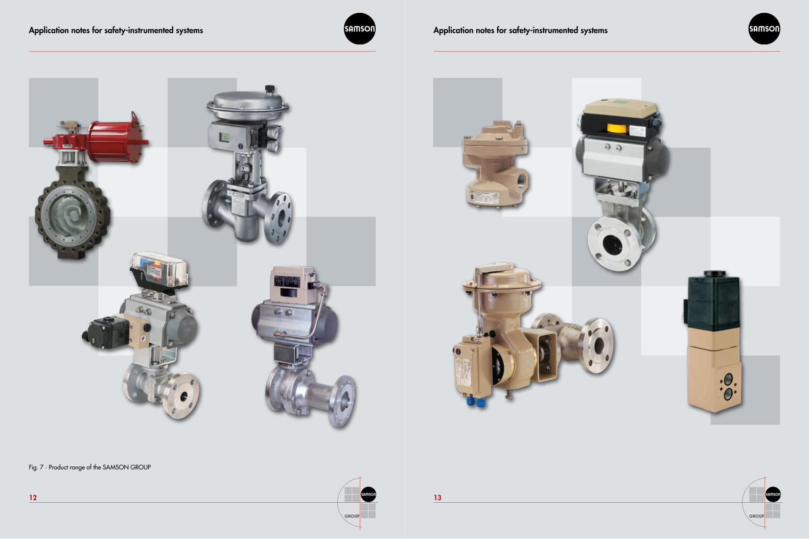
Fig. 7 · Product range of the SAMSON GROUP
Application notes for safety-instrumented systems
14
Application notes for safety-instrumented systems
15
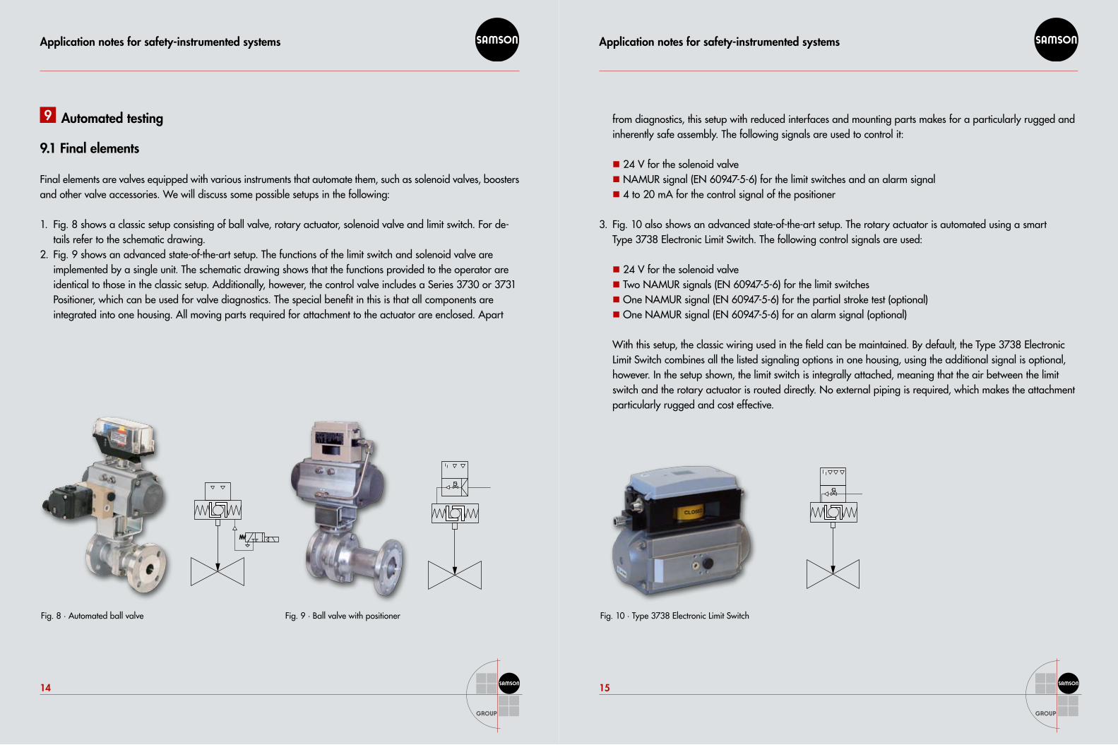
9 Automated testing
9.1 Final elements
Final elements are valves equipped with various instruments that automate them, such as solenoid valves, boosters and other valve accessories. We will discuss some possible setups in the following:
Fig. 8 shows a classic setup consisting of ball valve, rotary actuator, solenoid valve and limit switch. For de-1. tails refer to the schematic drawing.Fig. 9 shows an advanced state-of-the-art setup. The functions of the limit switch and solenoid valve are 2. implemented by a single unit. The schematic drawing shows that the functions provided to the operator are identical to those in the classic setup. Additionally, however, the control valve includes a Series 3730 or 3731 Positioner, which can be used for valve diagnostics. The special benefit in this is that all components are integrated into one housing. All moving parts required for attachment to the actuator are enclosed. Apart
Fig. 8 · Automated ball valve Fig. 9 · Ball valve with positioner
from diagnostics, this setup with reduced interfaces and mounting parts makes for a particularly rugged and inherently safe assembly. The following signals are used to control it:
24 V for the solenoid valve��
NAMUR signal (EN 60947-5-6) for the limit switches and an alarm signal��
4 to 20 mA for the control signal of the positioner��
Fig. 10 also shows an advanced state-of-the-art setup. The rotary actuator is automated using a smart 3. Type 3738 Electronic Limit Switch. The following control signals are used:
24 V for the solenoid valve��
Two NAMUR signals (EN 60947-5-6) for the limit switches��
One NAMUR signal (EN 60947-5-6) for the partial stroke test (optional)��
One NAMUR signal (EN 60947-5-6) for an alarm signal (optional) ��
With this setup, the classic wiring used in the field can be maintained. By default, the Type 3738 Electronic Limit Switch combines all the listed signaling options in one housing, using the additional signal is optional, however. In the setup shown, the limit switch is integrally attached, meaning that the air between the limit switch and the rotary actuator is routed directly. No external piping is required, which makes the attachment particularly rugged and cost effective.
Fig. 10 · Type 3738 Electronic Limit Switch
Application notes for safety-instrumented systems
16
Application notes for safety-instrumented systems
17
9.2 Test methods
The setups described above in items 2 and 3 permit automated online tests to be performed according to VDI 2180, Part 5, section 4.6. The following parts can be automated or supported by automated units:
Test sequence��
Data recording��
Data archiving ��
The setup ensures reproducible and consistent testing. This method is superior to manual testing and manual data recording merely based on quality.
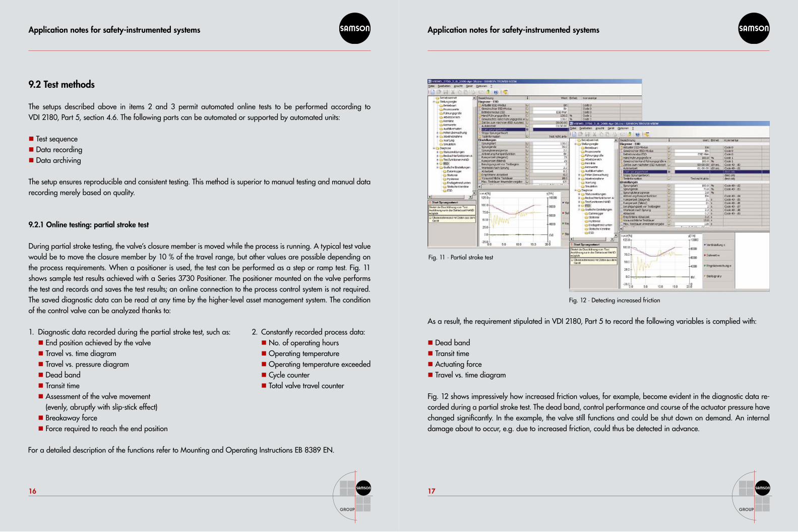
9.2.1 Online testing: partial stroke test
During partial stroke testing, the valve’s closure member is moved while the process is running. A typical test value would be to move the closure member by 10 % of the travel range, but other values are possible depending on the process requirements. When a positioner is used, the test can be performed as a step or ramp test. Fig. 11 shows sample test results achieved with a Series 3730 Positioner. The positioner mounted on the valve performs the test and records and saves the test results; an online connection to the process control system is not required. The saved diagnostic data can be read at any time by the higher-level asset management system. The condition of the control valve can be analyzed thanks to:
As a result, the requirement stipulated in VDI 2180, Part 5 to record the following variables is complied with:
Dead band��
Transit time��
Actuating force��
Travel vs. time diagram��
Fig. 12 shows impressively how increased friction values, for example, become evident in the diagnostic data re-corded during a partial stroke test. The dead band, control performance and course of the actuator pressure have changed significantly. In the example, the valve still functions and could be shut down on demand. An internal damage about to occur, e.g. due to increased friction, could thus be detected in advance.
Fig. 11 · Partial stroke test
Fig. 12 · Detecting increased friction
Diagnostic data recorded during the partial stroke test, such as:1. End position achieved by the valve��
Travel vs. time diagram��
Travel vs. pressure diagram��
Dead band��
Transit time��
Assessment of the valve movement ��
(evenly, abruptly with slip-stick effect)Breakaway force��
Force required to reach the end position ��
Constantly recorded process data:2. No. of operating hours��
Operating temperature��
Operating temperature exceeded��
Cycle counter��
Total valve travel counter��
For a detailed description of the functions refer to Mounting and Operating Instructions EB 8389 EN.
Application notes for safety-instrumented systems
18
Application notes for safety-instrumented systems
19
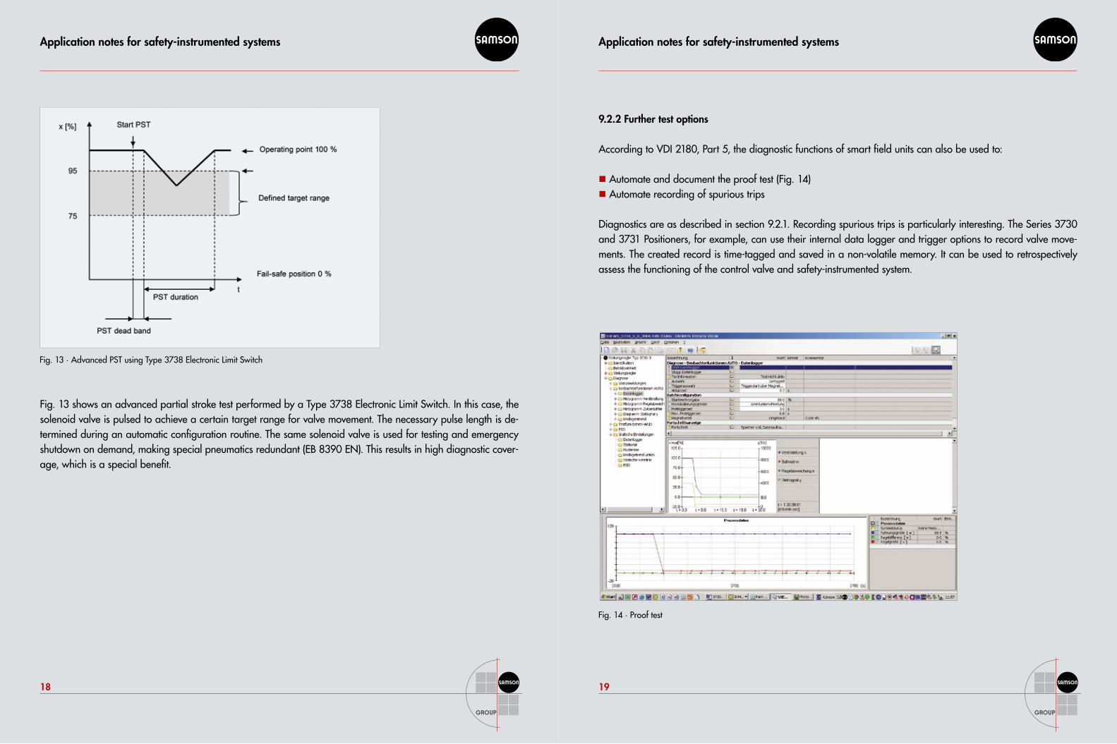
Fig. 13 shows an advanced partial stroke test performed by a Type 3738 Electronic Limit Switch. In this case, the solenoid valve is pulsed to achieve a certain target range for valve movement. The necessary pulse length is de-termined during an automatic configuration routine. The same solenoid valve is used for testing and emergency shutdown on demand, making special pneumatics redundant (EB 8390 EN). This results in high diagnostic cover-age, which is a special benefit.
Fig. 14 · Proof test
Fig. 13 · Advanced PST using Type 3738 Electronic Limit Switch
9.2.2 Further test options
According to VDI 2180, Part 5, the diagnostic functions of smart field units can also be used to:
Automate and document the proof test (Fig. 14)��
Automate recording of spurious trips��
Diagnostics are as described in section 9.2.1. Recording spurious trips is particularly interesting. The Series 3730 and 3731 Positioners, for example, can use their internal data logger and trigger options to record valve move-ments. The created record is time-tagged and saved in a non-volatile memory. It can be used to retrospectively assess the functioning of the control valve and safety-instrumented system.
Application notes for safety-instrumented systems
20
Application notes for safety-instrumented systems
21
9.3 Integration into the process control system
9.3.1 Architecture
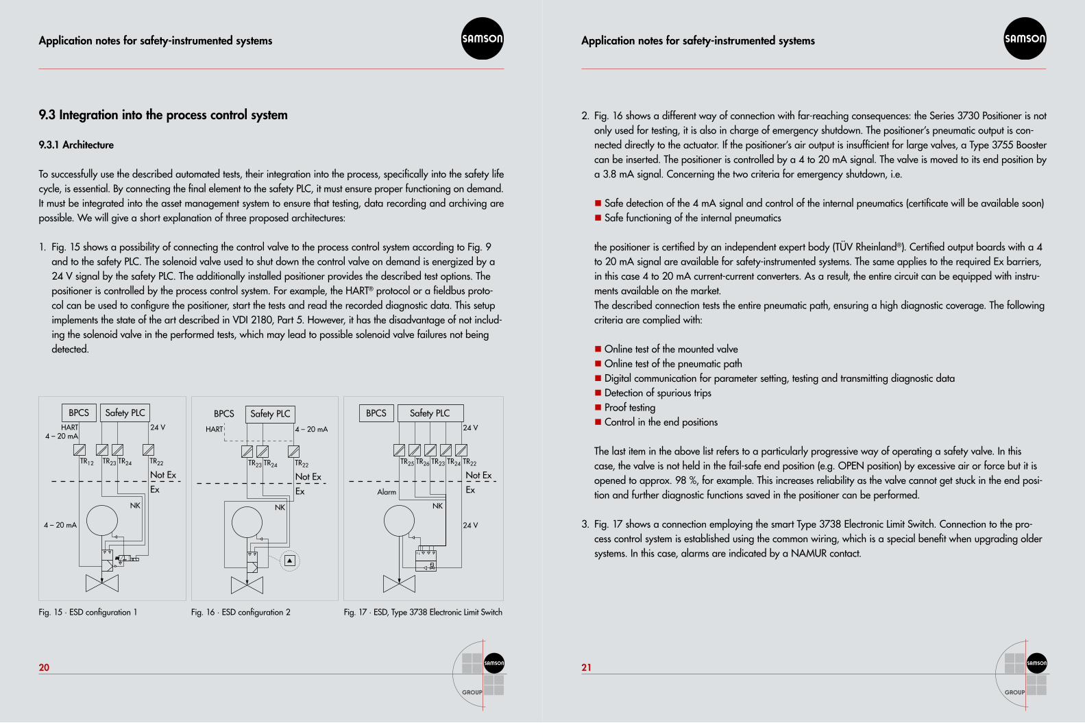
To successfully use the described automated tests, their integration into the process, specifically into the safety life cycle, is essential. By connecting the final element to the safety PLC, it must ensure proper functioning on demand. It must be integrated into the asset management system to ensure that testing, data recording and archiving are possible. We will give a short explanation of three proposed architectures:
Fig. 15 shows a possibility of connecting the control valve to the process control system according to Fig. 9 1. and to the safety PLC. The solenoid valve used to shut down the control valve on demand is energized by a 24 V signal by the safety PLC. The additionally installed positioner provides the described test options. The positioner is controlled by the process control system. For example, the HART® protocol or a fieldbus proto-col can be used to configure the positioner, start the tests and read the recorded diagnostic data. This setup implements the state of the art described in VDI 2180, Part 5. However, it has the disadvantage of not includ-ing the solenoid valve in the performed tests, which may lead to possible solenoid valve failures not being detected.
BPCS
TR12
Not Ex
HART4 – 20 mA
24 V
4 – 20 mA
NK
Ex
TR24TR23
Safety PLC
TR22
HART 4 – 20 mA
NK
BPCS
TR23 TR24
Safety PLC
TR22
Not Ex
Ex
24 V
24 V
BPCS
TR25 TR23TR26
Safety PLC
TR24 TR22
NK
Alarm
Not Ex
Ex
Fig. 15 · ESD configuration 1 Fig. 16 · ESD configuration 2 Fig. 17 · ESD, Type 3738 Electronic Limit Switch
Fig. 16 shows a different way of connection with far-reaching consequences: the Series 3730 Positioner is not 2. only used for testing, it is also in charge of emergency shutdown. The positioner’s pneumatic output is con-nected directly to the actuator. If the positioner’s air output is insufficient for large valves, a Type 3755 Booster can be inserted. The positioner is controlled by a 4 to 20 mA signal. The valve is moved to its end position by a 3.8 mA signal. Concerning the two criteria for emergency shutdown, i.e.
Safe detection of the 4 mA signal and control of the internal pneumatics (certificate will be available soon)��
Safe functioning of the internal pneumatics ��
the positioner is certified by an independent expert body (TÜV Rheinland®). Certified output boards with a 4 to 20 mA signal are available for safety-instrumented systems. The same applies to the required Ex barriers, in this case 4 to 20 mA current-current converters. As a result, the entire circuit can be equipped with instru-ments available on the market. The described connection tests the entire pneumatic path, ensuring a high diagnostic coverage. The following criteria are complied with:
Online test of the mounted valve��
Online test of the pneumatic path��
Digital communication for parameter setting, testing and transmitting diagnostic data��
Detection of spurious trips��
Proof testing��
Control in the end positions ��
The last item in the above list refers to a particularly progressive way of operating a safety valve. In this case, the valve is not held in the fail-safe end position (e.g. OPEN position) by excessive air or force but it is opened to approx. 98 %, for example. This increases reliability as the valve cannot get stuck in the end posi-tion and further diagnostic functions saved in the positioner can be performed.
Fig. 17 shows a connection employing the smart Type 3738 Electronic Limit Switch. Connection to the pro-3. cess control system is established using the common wiring, which is a special benefit when upgrading older systems. In this case, alarms are indicated by a NAMUR contact.
Application notes for safety-instrumented systems
22
Application notes for safety-instrumented systems
23
9.3.2 Documentation of partial stroke testing
If the test results are to be used, e.g. to achieve a longer test interval, performance of the partial stroke test must be documented. To do so, a setup as shown in Fig. 17 (schematic drawing in Fig. 18) can be used. The limit switch of the Type 3730-x Positioner or the third travel contact of the Type 3738 Electronic Limit Switch are set to the desired valve movement target. In the positioner, this can be done using the mechanical travel stop option, which is a certified component. In the limit switch, the function of the NAMUR signal safely indicating the adjusted switching points has been certified by an independent expert body. The limit switch signal is recorded by the safety PLC, time-tagged and archived.
9.3.2 Continuous workflow
A full test cycle can be divided into the following steps:Test is triggered��
Test is performed (valve moved to target position)��
Data are recorded��
Data are saved��
Data are assessed��
Alarms are generated��
Data are saved to a tamper-proof archive��
Trends are generated based on several test cycles��
Fig. 18 · PST registration by safety PLC (photo by HIMA)
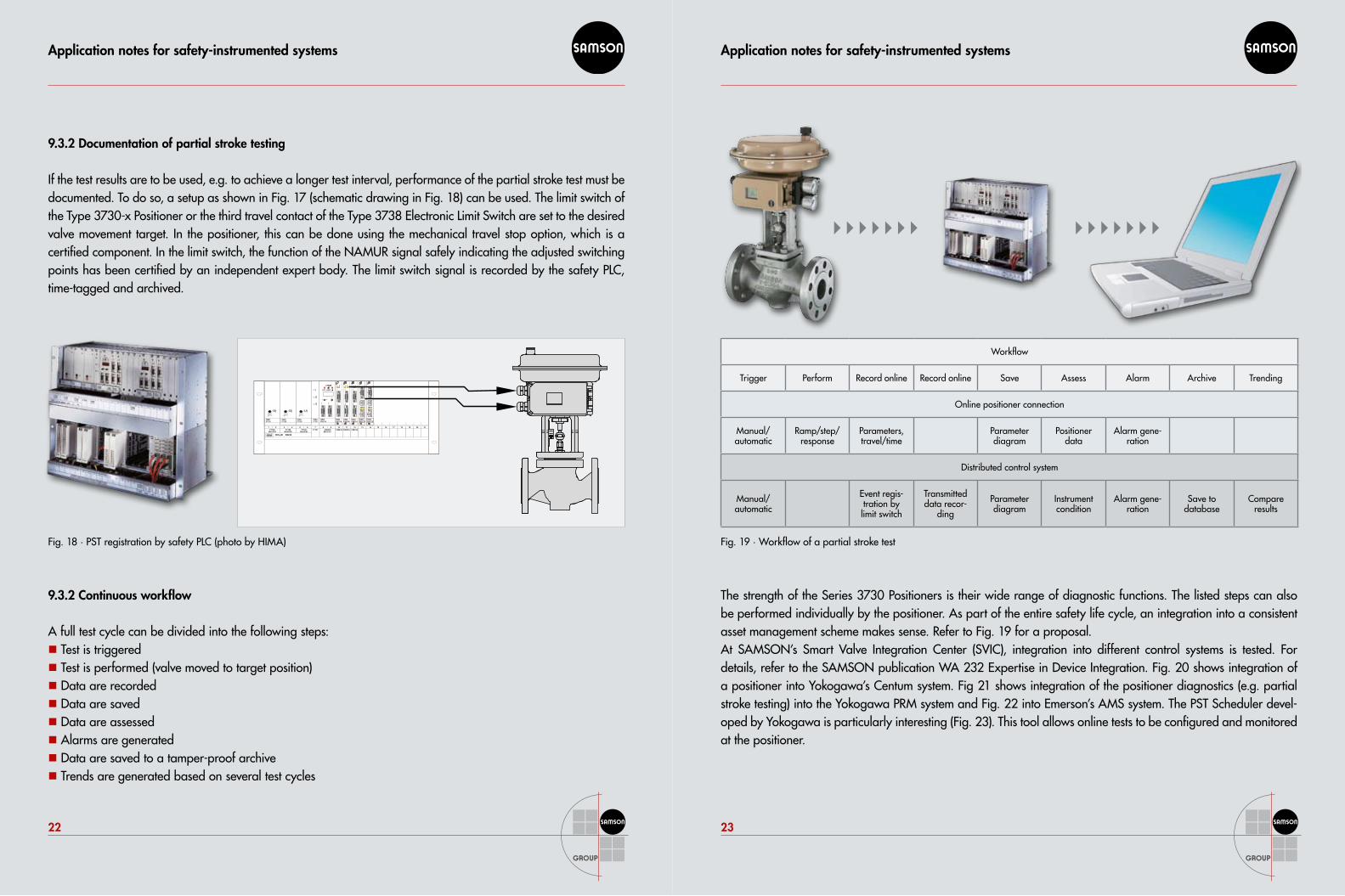
Workflow
Trigger Perform Record online Record online Save Assess Alarm Archive Trending
Online positioner connection
Manual/ automatic
Ramp/step/response
Parameters, travel/time
Parameter diagram
Positioner data
Alarm gene-ration
Distributed control system
Manual/ automatic
Event regis-tration by limit switch
Transmitted data recor-
ding
Parameter diagram
Instrument condition
Alarm gene-ration
Save to database
Compare results
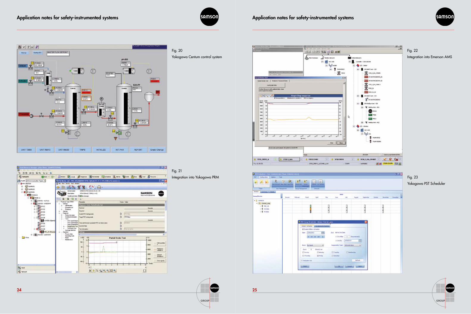
The strength of the Series 3730 Positioners is their wide range of diagnostic functions. The listed steps can also be performed individually by the positioner. As part of the entire safety life cycle, an integration into a consistent asset management scheme makes sense. Refer to Fig. 19 for a proposal.At SAMSON’s Smart Valve Integration Center (SVIC), integration into different control systems is tested. For details, refer to the SAMSON publication WA 232 Expertise in Device Integration. Fig. 20 shows integration of a positioner into Yokogawa’s Centum system. Fig 21 shows integration of the positioner diagnostics (e.g. partial stroke testing) into the Yokogawa PRM system and Fig. 22 into Emerson’s AMS system. The PST Scheduler devel-oped by Yokogawa is particularly interesting (Fig. 23). This tool allows online tests to be configured and monitored at the positioner.
Fig. 19 · Workflow of a partial stroke test
F7126 F7126 F7126 F7131 F8651X F8621A F8621A F8621A
H51q-M B5230NG1/PS1 NG2/PS2 NG3/PS3 ZB1/CU1
1 2 3 4 5 6 7 8 9 10 11 12 13 14 15 16 17 18 19 20 21
HIMAF8627X
1 2
1
2
1 2
1
2
1 2
1
21 2
HIMAF8621A
HIMAF8621A
HIMAF8621A
HIMAF8627X
HIMAF8651X
HIMAF7126
HIMAF7131
HIMAF7126
HIMAF7126
HSR
10B
aseT
HSR
TX COL
ERR
FB
RUNRED
FB
10B
aseT
HSR
TX COL
ERR
FB
RUNRED
FB
Application notes for safety-instrumented systems
24
Application notes for safety-instrumented systems
25
Fig. 20
Yokogawa Centum control system
Fig. 21
Integration into Yokogawa PRM Fig. 23
Yokogawa PST Scheduler
Fig. 22
Integration into Emerson AMS
Application notes for safety-instrumented systems
26
Application notes for safety-instrumented systems
27
9.4 Effects on risk analysis
9.4.1 Systematic failures
Rule out systematic failures by risk analysis and taking appropriate measures. Particularly in new processes or with test intervals exceeding the standard, it may make sense to take special measures to reveal undetected systematic failures. According to VDI 2180, Part 5, section 4.6, automated online tests can additionally protect the system against undetected systematic faults.
9.4.2 Random failures
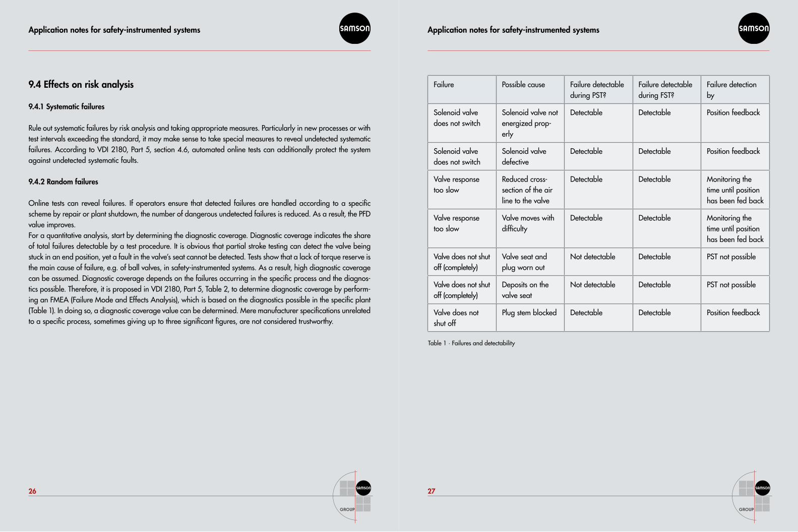
Online tests can reveal failures. If operators ensure that detected failures are handled according to a specific scheme by repair or plant shutdown, the number of dangerous undetected failures is reduced. As a result, the PFD value improves.For a quantitative analysis, start by determining the diagnostic coverage. Diagnostic coverage indicates the share of total failures detectable by a test procedure. It is obvious that partial stroke testing can detect the valve being stuck in an end position, yet a fault in the valve’s seat cannot be detected. Tests show that a lack of torque reserve is the main cause of failure, e.g. of ball valves, in safety-instrumented systems. As a result, high diagnostic coverage can be assumed. Diagnostic coverage depends on the failures occurring in the specific process and the diagnos-tics possible. Therefore, it is proposed in VDI 2180, Part 5, Table 2, to determine diagnostic coverage by perform-ing an FMEA (Failure Mode and Effects Analysis), which is based on the diagnostics possible in the specific plant (Table 1). In doing so, a diagnostic coverage value can be determined. Mere manufacturer specifications unrelated to a specific process, sometimes giving up to three significant figures, are not considered trustworthy.
Table 1 · Failures and detectability
Failure Possible cause Failure detectable during PST?
Failure detectable during FST?
Failure detection by
Solenoid valve does not switch
Solenoid valve not energized prop-erly
Detectable Detectable Position feedback
Solenoid valve does not switch
Solenoid valve defective
Detectable Detectable Position feedback
Valve response too slow
Reduced cross-section of the air line to the valve
Detectable Detectable Monitoring the time until position has been fed back
Valve response too slow
Valve moves with difficulty
Detectable Detectable Monitoring the time until position has been fed back
Valve does not shut off (completely)
Valve seat and plug worn out
Not detectable Detectable PST not possible
Valve does not shut off (completely)
Deposits on the valve seat
Not detectable Detectable PST not possible
Valve does not shut off
Plug stem blocked Detectable Detectable Position feedback
Application notes for safety-instrumented systems
28
Application notes for safety-instrumented systems
2928
If diagnostic coverage has been determined, the improved PFD value can be calculated according to formula (3):
Formula (3) PFD = ½ λdu · DC · TPST + ½ λdu · (1 – DC) · TPR PFD: Probability of Failure on Demand λdu: Total dangerous undetected failure rate (1/h)DC: Diagnostic coverageTPST: PST intervalTPR: Proof test interval
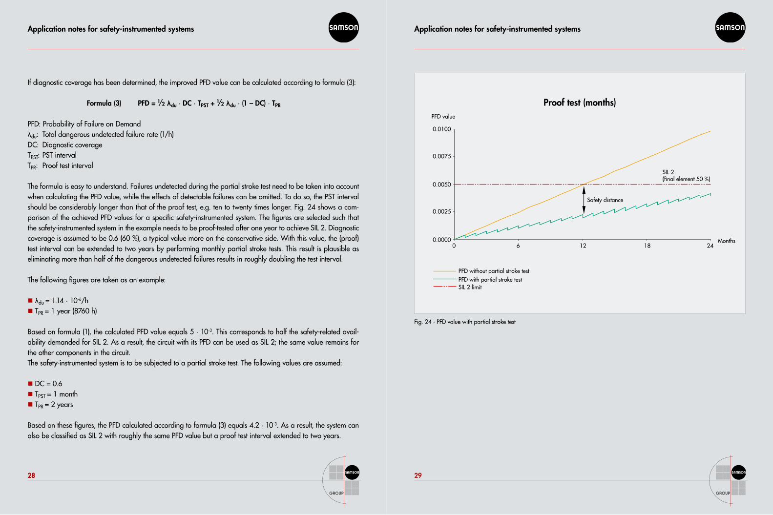
The formula is easy to understand. Failures undetected during the partial stroke test need to be taken into account when calculating the PFD value, while the effects of detectable failures can be omitted. To do so, the PST interval should be considerably longer than that of the proof test, e.g. ten to twenty times longer. Fig. 24 shows a com-parison of the achieved PFD values for a specific safety-instrumented system. The figures are selected such that the safety-instrumented system in the example needs to be proof-tested after one year to achieve SIL 2. Diagnostic coverage is assumed to be 0.6 (60 %), a typical value more on the conservative side. With this value, the (proof) test interval can be extended to two years by performing monthly partial stroke tests. This result is plausible as eliminating more than half of the dangerous undetected failures results in roughly doubling the test interval.
The following figures are taken as an example:
λ�� du = 1.14 · 10-6/hT�� PR = 1 year (8760 h)
Based on formula (1), the calculated PFD value equals 5 · 10-3. This corresponds to half the safety-related avail-ability demanded for SIL 2. As a result, the circuit with its PFD can be used as SIL 2; the same value remains for the other components in the circuit.The safety-instrumented system is to be subjected to a partial stroke test. The following values are assumed:
DC = 0.6 ��
T�� PST = 1 monthT�� PR = 2 years
Based on these figures, the PFD calculated according to formula (3) equals 4.2 · 10-3. As a result, the system can also be classified as SIL 2 with roughly the same PFD value but a proof test interval extended to two years.
Fig. 24 · PFD value with partial stroke test
0.0100
0.0075
0.0050
0.0025
0.0000
PFD without partial stroke testPFD with partial stroke testSIL 2 limit
SIL 2(final element 50 %)
Safety distance
0 6 12 18 24
PFD value
Months
Proof test (months)
Application notes for safety-instrumented systems
30
Application notes for safety-instrumented systems
31
9.4.3 Fault tolerance measures
IEC 61511 and VDI 2180 set a strict limit: single-channel instrumentation is only permissible up to SIL 2 and only if proven-in-use instruments are used. A safety-instrumented system complying with SIL 3 requires redundancy, i.e. two control valves. This requirement is not affected by online testing.
10 Life cycle
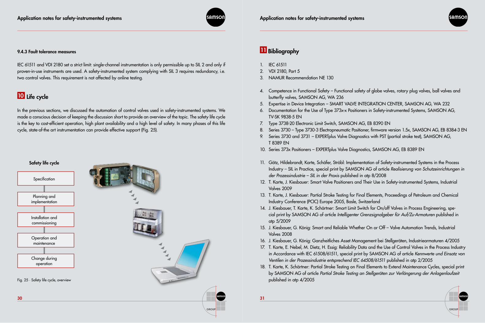
In the previous sections, we discussed the automation of control valves used in safety-instrumented systems. We made a conscious decision of keeping the discussion short to provide an overview of the topic. The safety life cycle is the key to cost-efficient operation, high plant availability and a high level of safety. In many phases of this life cycle, state-of-the art instrumentation can provide effective support (Fig. 25).
Fig. 25 · Safety life cycle, overview
11 Bibliography
IEC 615111. VDI 2180, Part 52. NAMUR Recommendation NE 130 3.
Competence in Functional Safety – Functional safety of globe valves, rotary plug valves, ball valves and 4. butterfly valves, SAMSON AG, WA 236Expertise in Device Integration – SMART VALVE INTEGRATION CENTER, SAMSON AG, WA 2325. Documentation for the Use of Type 373x-x Positioners in Safety-instrumented Systems, SAMSON AG, 6. TV-SK 9838-5 ENType 3738-20 Electronic Limit Switch, SAMSON AG, EB 8390 EN7. Series 3730 – Type 3730-3 Electropneumatic Positioner, firmware version 1.5x, SAMSON AG, EB 8384-3 EN8. Series 3730 and 3731 – EXPERTplus Valve Diagnostics with PST (partial stroke test), SAMSON AG, 9. T 8389 ENSeries 373x Positioners – EXPERTplus Valve Diagnostics, SAMSON AG, EB 8389 EN 10.
Götz, Hildebrandt, Karte, Schäfer, Ströbl: Implementation of Safety-instrumented Systems in the Process 11. Industry – SIL in Practice, special print by SAMSON AG of article Realisierung von Schutzeinrichtungen in der Prozessindustrie – SIL in der Praxis published in atp 8/2008T. Karte, J. Kiesbauer: Smart Valve Positioners and Their Use in Safety-instrumented Systems, Industrial 12. Valves 2009T. Karte, J. Kiesbauer: Partial Stroke Testing for Final Elements, Proceedings of Petroleum and Chemical 13. Industry Conference (PCIC) Europe 2005, Basle, SwitzerlandJ. Kiesbauer, T. Karte, K. Schärtner: Smart Limit Switch for On/off Valves in Process Engineering, spe-14. cial print by SAMSON AG of article Intelligenter Grenzsignalgeber für Auf/Zu-Armaturen published in atp 5/2009J. Kiesbauer, G. König: Smart and Reliable Whether On or Off – Valve Automation Trends, Industrial 15. Valves 2008J. Kiesbauer, G. König: Ganzheitliches Asset Management bei Stellgeräten, Industriearmaturen 4/200516. T. Karte, E. Nebel, M. Dietz, H. Essig: Reliability Data and the Use of Control Valves in the Process Industry 17. in Accordance with IEC 61508/61511, special print by SAMSON AG of article Kennwerte und Einsatz von Ventilen in der Prozessindustrie entsprechend IEC 64508/61511 published in atp 2/2005T. Karte, K. Schärtner: Partial Stroke Testing on Final Elements to Extend Maintenance Cycles, special print 18. by SAMSON AG of article Partial Stroke Testing an Stellgeräten zur Verlängerung der Anlagenlaufzeit published in atp 4/2005
Safety life cycle
Specification
Planning and implementation
Installation and commissioning
Operation and maintenance
Change during operation

2010
-10
HD
· W
A 2
39 E
N
SAMSON AG · MESS- UND REGELTECHNIK Weismüllerstraße 3 · 60314 Frankfurt am Main · Germany Phone: +49 69 4009-0 · Fax: +49 69 4009-1507 E-mail: [email protected] · Internet: www.samson.de
Global presence with a local touch