Embed Size (px)
Citation preview

Brought to you by PCS Electronics, www.pcs-electronics.com1
PCIMAX3000+High performance PC based FM stereo transmitter with RDS
Manual

Brought to you by PCS Electronics, www.pcs-electronics.com2
I M P O R T A N T N O T E
Upon receiving your order inspect the packaging material and unit for apparent damage. Anydamage should be reported immediately so we can make a claim with the shipping company.Take photos, if you can, they can be used as a proof.
Drivers are available here: http://www.pcs-electronics.com/phpBB2/viewtopic.php?t=2409
Make sure to connect power to the card, it accepts the 3,5” power connector that used to servefor hard drives and CD ROMs before SATA came along. Several of these are usually availableinside any PC. Also connect the USB jumper cable.
IMPORTANT!: If you want to connect an amplifier to this transmitter please first make sure thatoutput power is set correctly and does not exceed maximum allowable input power of theamplifier.
Study local regulations and ensure that you are always operating in compliance, it is yourresponsibility to always comply with laws.

Brought to you by PCS Electronics, www.pcs-electronics.com3
TABLE OF CONTENTS
INTRODUCING THE PCIMAX 3000+ PC FM TRANSMITTER............................................................... 4
WHAT MAKES THIS PC FM TRANSMITTER SO GREAT?...................................................................................... 4HOW IS PCIMAX3000+ BETTER THAN PCIMAX2007+?................................................................................. 4TECHNICAL SPECIFICATIONS: .......................................................................................................................... 5THANK YOU FOR PURCHASING PCIMAX3000+ ............................................................................................... 5
PCIMAX 3000+ BOARD LAYOUT............................................................................................................... 6
BOARD LAYOUT ............................................................................................................................................. 6
BEFORE YOU START .................................................................................................................................. 8
ANTENNA....................................................................................................................................................... 8SO WHAT IS THIS SWR (VSWR) EVERYONE TALKS ABOUT?................................................................................. 9COAXIAL CABLE ............................................................................................................................................. 9CONNECTORS ................................................................................................................................................. 9MAINS POWER SUPPLY AND MAINS POWER CABLE – MAY NOT APPLY TO YOUR PRODUCT ................................... 9AUDIO PROCESSING AND SCHEDULING SOFTWARE.......................................................................................... 10ENCLOSURE AND SUITABLE COOLING FOR PCIMAX3000+ ............................................................................ 10
INSTALLING THE PCI MAX 3000+ INTO YOUR PC ............................................................................. 11
WIRING THINGS UP AND FIRST POWER-UP....................................................................................................... 11
USING THE PCIMAX3000+ PC FM EXCITER ........................................................................................ 12
CHANGING FREQUENCY ................................................................................................................................ 12<RF POWER>..........................................................................................ERROR! BOOKMARK NOT DEFINED.
TROUBLESHOOTING ............................................................................................................................... 21
APPENDIX A: DIY ANTENNA AND IMPROVEMENT TIPS ................................................................. 23
SIMPLE GP ANTENNA DESIGN........................................................................................................................ 23SOME MORE IMPROVEMENT TIPS.................................................................................................................... 23
APPENDIX B – USB PORT SOFTWARE .................................................................................................. 24
NEEDED FILES .............................................................................................................................................. 24INSTALLING THE USB DRIVER....................................................................................................................... 24CONFIGURING USB DRIVER .......................................................................................................................... 24CONFIGURING COMMUNICATIONS PORT IN CYBERMAXMICRO+ CONTROL PROGRAMERROR! BOOKMARK NOTDEFINED.CONFIGURING AUDIO PLAYBACK................................................................................................................... 26
APPENDIX C: GENERAL TIPS FOR SETTING UP TRANSMITTERS................................................. 27
TYPICAL FM TRANSMITTER SETUPS .............................................................................................................. 27TYPICAL FM BROADCASTING ANTENNA SETUPS............................................................................................. 28WIRING ANTENNAS IN MULTI-BAY CONFIGURATIONS ..................................................................................... 29
APPENDIX D – WARRANTY AND LEGAL INFO ................................................................................... 36
IMPORTANT NOTICE!..................................................................................................................................... 36WARRANTY AND SERVICING! ........................................................................................................................ 36LEGAL INFO.................................................................................................................................................. 36LIMITATION OF LIABILITY ............................................................................................................................. 36
ALSO AVAILABLE FROM WWW.PCS-ELECTRONICS.COM............................................................. 37
REVISIONS AND ERRATA........................................................................................................................ 38
INDEX........................................................................................................................................................... 38

Brought to you by PCS Electronics, www.pcs-electronics.com4
Introducing the PCIMAX 3000+ PC FM transmitterNext generation of FM exciters with new Qsonic VCO/PLL and digital audio streaming
he PCI MAX 3000+ is a high performance PLL controlled FM stereo transmitter with optional RDS for youreveryday PC compatible computer. It is all-in-one solution, perfect for transmitting your music throughout yourhouse, your yard and further, if you couple it with our new 15W/25W or 40W booster+. It can even serve as alocal, college or a community radio station, with the features and quality you expect from the professional setup,
with amazing audio quality and stereo separation. It is perfectly suited for homebrew DJ’s. It is easily tunable anywhere onthe dial with a simple click of the mouse. Since this product has been featured in the Playboy magazine (June 2002) we soldthousands of these cards, but our customers demanded even more power and features. And now they are here; this PC FMtransmitter brings direct digital audio streaming and brand new technology, Qsonic PLL/VCO subsystem with impressiveaudio performance and excellent bass response.
What makes this PC FM transmitter so great?Although PCIMAX3000+ is primarily a PC based FM exciter with built-in stereo encoder which easily upgrades to RDS itcan also be used outside of a PC as a stand-alone product (exciter). It can easily drive many amplifiers that require up to 3Wof drive power. It can either accept audio via standard 3.5” audio jack or in digital form via USB. It can even acceptmicrophone input and it will automatically mute music while you speak. The new Qsonic VCO/PLL subsystem is protectedby a metal shield for even better performance. Power and all other parameters can be controlled with Windows controlsoftware. Software itself was improved greatly and also supports reading output power and temperature from the card. Thereshould be far less problems with it than in previous versions. Of course this unit is completely no-tune and offers incredibleperformance 24/7/365. Even as a stand-alone unit this exciter doubles as an excellent community radio station and caneasily cover a small city with suitable antenna and 15W-40W booster.
How is PCIMAX3000+ better than PCIMAX2007+?- Put simply into one sentence: There has never been a more major update to the PCIMAX line before- PCIMAX3000+ has microphone input- PCIMAX3000+ has the new Qsonic PLL/VCO subsystem- PCIMAX3000+ has on-board sound card and allows direct digital audio streaming at reduced noise- You can use PCIMAX3000+ in computers without sound cards- PCIMAX3000+ can even be used with laptops, but we recommend that you put PCIMAX 3000+ into an enclosure.- PCIMAX3000+ has flat audio modulation sensitivity across entire FM band- PCIMAX3000+ has better bass response- PCIMAX3000+ control software shows approximate measured output power and output stage temperature- PCIMAX3000+ has on-board ALC (Automatic Level Control) trimmer- With PCIMAX3000+ it is much easier to write control software and integrate its functions into other programs. Contact usfor sample applications.- PCIMAX3000+ gives full output power with internal PC power supply.
Chapter
1T

Brought to you by PCS Electronics, www.pcs-electronics.com5
Technical specifications:- RF output power: 0 to 3 Watts (variable via windows control program)- Output connector: F female, 50 Ohms- Frequency range: 87.5-108MHz- PLL steps: 50KHz- Frequency stability: +/- 100Hz- Spurious/Harmonic rejection: Harmonics: >50dB, Spurious: -80dB- Power supply: Internal 5.25” drive power or external 11-15V/1A- External power connector: 2.1mm power socket, center (+)- Quartz locked PLL frequency control, ultra stable & clean output- Audio performance: Flat sensitivity across FM band, less than 0.1% distortion, 20Hz-75KHz- RF output ruggedness: SWR protection- Polarity protection, temp protection- Over-current protection- Pre-emphasis, 50uS, 75uS or none selectable- Audio Input Impedance: 600ohm, phono 3.5”- Microphone input line: RCA jack, either powered (electret mic –install MIC PWR jumper) or other type (no jumper)- Audio Input Level: 0 dB- S/N ratio: >90 dB
Thank you for purchasing PCIMAX3000+We hope you will enjoy it as much as we do and remember to tell your friends about it. Please feel free to leave yourcomments at our website or post your experience in our forum. From all of us we wish you happy broadcasting!
Your PCS Electronics team

Brought to you by PCS Electronics, www.pcs-electronics.com6
PCIMAX 3000+ board layoutBoard layout
Fig. 1: PCIMAX 3000+ board layout
Chapter
2

Brought to you by PCS Electronics, www.pcs-electronics.com7
Ref. Function
A Place for PC 5.25” drive power plug
B Place for optional LCD control display
C RS232 jumper for the RDS daughter board
D Plug in RDS daughter board here
E Regular analog audio input, stereo 3.5” socket
F Microphone input, regular RCA socket, center can be powered for electret mic (install MIC PWR jumper)
G This is for powering electret microphone. Install, if using electret mic.
H Install, if you want to disable automatic background music mute during speech.
I USB socket for digital audio streaming and USB remote control.
J External power supply, 2.1mm jack. Provice 11-15V DC @ 1A, stabilized. Center is positive.
K RF output. F female socket. Connect antenna here. Do not operate without antenna!
L,M
Pre-emphasis jumpers. For EU and most of the world install to the 50uS position. For americas install into 75uSposition.
N In MicroMax we use this jumper to connect power on/off switch. In regular operation install jumper here.Table 1: Description of various elements of the PCIMAX 3000+ PC FM transmitter board

Brought to you by PCS Electronics, www.pcs-electronics.com8
Before you startIf this is your first step into the world of radio, it is recommended that you read this section before you power your unit upfor the first time. Let us clear up some basics you should know about. You will also find some useful tips in our guides andforum at http://www.pcs-electronics.com. Here is what you need to get your TV transmitter on the air:
AntennaPreferred type of antenna is affected by several factors, but mostly by desired radiation pattern, space available and yourbudget. If you are located in the middle of the area you want to cover you'll need an omni-directional antenna whichtransmits equally in all directions. If you are located at the edge of your desired coverage area you can beam the signal intothe target area with a directional antenna. Directional antennas are also practical for point-to-point communications.Another thing to consider is that directional antennas usually have much higher gain than omni-directional antennas sincethe power which is radiated in all directions with omni antenna is concentrated mainly into one direction with directionalantenna. Antennas with more gain thus have narrower beam. A compromise is usually made depending on budget andspace available, higher gain antennas are often bigger and often more expensive.
Once you’ve chosen and installed your antenna there is another thing to consider. You can read more about it in the nextsection (So what is this SWR everyone talks about). Before powering up your transmitter on the air you should tune yourantenna to get minimal SWR. This is typically done by adjusting the position of the antenna and any adjustable pieces. Aimfor 2:1 or less. Use low power into the antenna when tuning it up and making adjustments. If you were using full power anda bit of the antenna came off in your hand the VSWR could be so bad as to blow the final transistor. For the same reasoncheck the DC continuity of the antenna with an ohmmeter before plugging it in, to be sure it's what it's meant to be, either ashort circuit or an open one, depending on the antenna type. For instructions regarding construction of antennas please seeour website: http://www.pcs-electronics.com (guides section - antennas).
Antenna is a crucial part of the system so take special care. It is usually a good idea to place antenna away from yourtransmitter, power supply and audio system. Also any transmitter should be in a metal case which shields circuitry from theradiation of the antenna. If you cannot meet these requirements, you could experience feedback and other RF problems. Wecannot guarantee proper operation of any transmitter/amplifier unless suitable antenna system is used and transmitters are inventilated metal enclosure! This applies to any transmitter. Interestingly, strong RF field can make CD players and otherdigital devices go bezerk. Try placing antenna next to yours and see what happens. Most of the modern audio gear is not RFshielded – reducing costs is unfortunately the mantra today. This is why keeping antenna away from audio gear is a goodidea.
If you are going to place your antenna outside, on your roof, please take care of the grounding. This should be done toprevent lightning hazard and should be done by a company specializing in lightning protection. You can read more aboutlightning protection in the book recommended below or many of the websites (Google up “lightning protection ham radio”for example) .
I hope this basic introduction will not scare you too much, it should be sufficient for the time being although we encourageyou to explore this exciting subject further with the help of a book such as the ARRL Antenna Book:http://www.amazon.com/exec/obidos/ASIN/0872598047/mightyspiraterad
Chapter
3

Brought to you by PCS Electronics, www.pcs-electronics.com9
So what is this swr (vswr) everyone talks about?SWR is a measure of how well two devices are impedance matched to each other. Typical radio/TV transmission equipmentis designed for 50 ohm load impedance, so we usually use 50 ohm cables and build or buy antennas that are specified for 50ohm. While most cables have flat impedance over frequency (they measure 50 ohm at all frequencies you are likely to use)the same is not true of the antennas.
A 1.0:1 VSWR is a perfect match. That means the load impedance is exactly 50 ohms. A 2.0:1 VSWR is obtained when theload impedance is either 25 ohms or 100 ohms.
Because most transmitters will deliver full power with a load VSWR of up to 2.0:1, this value is usually considered the limitfor acceptable operation. Many prefer to keep their VSWR below that however, but for all practical purposes, it isunnecessary to spend time or money trying to get much below a VSWR of 1.5:1. The benefits will be hard to measure andeven harder to notice.
On the other hand, coaxial cable losses increase rapidly, for a given frequency of operation, when the antenna VSWRexceeds 2.0:1. This can even, in some extreme cases, result in the coaxial cable burning, even when running 100 W. Using ahigher grade of cable will definitely improve things, but even high quality coaxial cable becomes very lossy when VSWRexceeds 3.0:1 at higher HF frequencies (or VHF and higher).
Coaxial cableCoaxial cable is an electrical cable consisting of a round, insulated conducting wire surrounded by a round, conductingsheath, usually surrounded by a final insulating layer. The cable is designed to carry a high-frequency or broadband signal,usually at radio frequencies. Coaxial Cabling is a two conductor closed transmission medium that is often used for thetransmission of RF energy. It yields excellent performance at high frequencies and superior EMI control/shielding whencompared to other types of copper cabling. Coaxial cabling is commonly found in broadcast and networking systems. Mostcoaxial cables have a characteristic impedance of either 50 or 75 ohms. The RF industry uses standard type-names for coaxialcables. The U.S military uses the RG-# or RG-#/U format (probably for "radio grade, universal", but other interpretationsexist).
The common RG-58 from Radio Shack is NOT the best you can do and can eat a lot of your effective power out! Use itonly for short runs. BELDEN makes terrific coaxial cable in various qualities and with very low loss (measured indB’s…decibels). 3 dB loss = 1/4 of your signal strength - either lost or gained. Watch out for the correct impedance; RG58,RG213, H-500 and H-155 have 50 Ohms, RG-59 and RG-6 have 75 Ohms. Most antennas and transmitters including oursare 50 ohm. Check our website for good coax. Don't buy more than you need to make the long run to your antenna anddon't make up a few "jumpers" to go between your exciter, VSWR meter and your antenna as all you'll do is create higherSWR and more line losses. H-155 or H500 are good choices! RG-142 with Teflon is recommended for wiring insidecabinets, for baluns, Wilkinson couplers and everywhere where resistance to heat is required as insulation won’t melt duringsoldering or operation.
ConnectorsA connector comes between coaxial cable and your transmitter. Our card has F female connector and for many this is notvery convenient. It is recommended that you get some kind of adapter, such as F male to BNC adapter or F male to Nfemale or F male to SO239 (CB); we offer all of these at our website. Than following the adapter install N, BNC or SO239on the cable, these are all standard VHF RF connectors. Try to find a good quality connector as cheap types usually usecheap plastic instead of Teflon. The good ones are usually easily recognized by higher prices. Another reliable method is atest with soldering iron; Teflon won’t melt while plastic will.
Mains power supply and mains power cable – may not apply to your productDo not underestimate the importance of mains power supply, despite abundance of all kinds of cheap units available todaythey unfortunately do not always meet requirements. What you need is a well stabilized DC 15V mains power supply thatcan supply at least 5 amps of continuous current without overheating, introducing buzzing, dropping the voltage down to12V or lower (a classic case) or acting up in other way. Whenever in doubt please buy our mains power supply. One finalnote, our units are set for 15V and if you use less this may lower your output power a bit. The lower the supply voltage thelower the power. You can compensate for this by slightly increasing output stage bias current.
If you ordered and received our mains power supply (which is recommended) you’ll notice the mains cable is not included,but can be obtained in any radio/computer/hardware shop at the cost of about 1 US$. It is the type used in your PC formains power. Since these cables vary from country to country and we had trouble getting the exact type locally we decidedagainst including them, especially since finding them is so easy locally.
Brought to you by PCS Electronics, www.pcs-electronics.com10
Audio processing and scheduling softwareYou need some kind of audio source to drive your transmitter. This will typically be a computer although you can plug anyaudio source into the 3.5” audio stereo socket. You will need some kind of playback and scheduling software. In most simpleform this is a simple Mp3 player, such as WinAmp. However you can do much better, software packages exist that offer aworld of features and options. We offer two of these on our website here, especially Jazler is very versatile and is used bymany professional radio stations out there:http://www.pcs-electronics.com/software-c-28.html
Enclosure and suitable cooling for PCIMAX3000+If you are going to use PCIMAX 3000+ in stand-alone mode outside of the PC, use metal (preferably aluminum) for yourenclosures and allow some free space for heat dissipation, also make ventilation holes at the top and/or back of theenclosure. Fix the PCB and heat-sink with all screws tightly. Make sure you tightly screw the rf board to the enclosureas this is how the output transistor dissipates its heat!

Brought to you by PCS Electronics, www.pcs-electronics.com11
Installing the PCI MAX 3000+ into your PCWiring things up and first power-upInstalling the PCIMAX3000+ is easy, just make sure you read the previous chapter to pick up some basic knowledge. Forbest range and performance or when used outside the PC also properly setup enclosure, antenna and coaxial cable. Thanproceed with the following:- Install the driver off a CD or download and install it from our website. Also install USB port driver.- Install PCIMAX3000+ in a PC as any other computer card. Power off the PC, disconnect mains power cord, open up theside cover and find a free PCI slot. Than insert PCIMAX card and secure it with a screw.- Insert the EIDE harddisk (4-pin) power cable into the back of the card.- Insert one end of the USB cable into the back of the card and the other end into any free USB ports.- Connect provided or other antenna into the end F corrector and secure the connector until tight.- Some air flow is recommended so if you have 3W version ensure some air flow is moving across the card.- Check everything again and replace the side cover, plug mains cable back in and power up the PC.- Let windows find the drivers for digital sound streaming and USB port. If something is missing look for drivers off ourwebsite and install as necessary.- Start the CyberMaxMicro windows program.- Turn on a radio receiver and set it to your intended transmitter frequency.- Set frequency and power as desired.- Wait a few seconds for the transmitter to lock onto frequency. Your radio should now mute since you did not connect anyaudio sources yet. If you want to play audio through the analog input on the card you can now connect that input to anyaudio source or sound card of the PC. The audio should be heard on the radio. You should not sound louder than otherstations, in fact unless you have an expensive high performance software or hardware sound processor you should soundslightly quieter than other stations (but less distorted).- You can set RDS parameters, but this only works when you have a RDS daughter board.- If you want to stream audio digitally, you have to let your audio playback software know which output it needs to use. Onsystem level you can specify default Windows audio playback device by going into Start>Settings>Control Palen> Soundand Audio Devices Properties. Here on the Audio tab select USB audio device and all audio will be streamed throughPCIMAX 3000+. Quite amazing how clear the audio is when you stream audio directly in digital fashion. Many radioscheduling programs, such as Jazler, Sam and others, will let you select through which audio device audio should play. Werecommend that you look at these choices.
Chapter
4

Brought to you by PCS Electronics, www.pcs-electronics.com12
Using the Windows control program
Setup
COM portSelect correct COM port here. Usually this would be COM1.
Communication test toolUse this feature to find correct settings easily. Try different settings and check them by clicking the button.
Chapter
5

Brought to you by PCS Electronics, www.pcs-electronics.com13
FM Transmitter
FM transmitter frequencySet the frequency by 0.5 or 0.05MHz step..
Transmitter output powerSet the desired output power.
Stereo/MonoSelect audio mode.
FM Transmitter statusThese are some FM transmitter status fields (read only).
Automatic refreshCheck this box to periodically read and refresh corensponding status fields of the FM transmitter status

Brought to you by PCS Electronics, www.pcs-electronics.com14
PI, PTY...
PI codeThis information consists of a code enabling the receiver to distinguish between countries, areas in which the sameprogramme is transmitted, and the identification of the programme itself. The code is not intended for direct displayand is assigned to each individual radio programme, to enable it to be distinguished from all other programmes. Oneimportant application of this information would be to enable the receiver to search automatically for an alternativefrequency in case of bad reception of the programme to which the receiver is tuned; the criteria for the change-overto the new frequency would be the presence of a better signal having the same Programme Identification code.
TP flagTP is a flag to indicate that the tuned program carries traffic announcements. The TP flag must only be set onprograms which dynamically switch on the TA identification during traffic announcements. The signal shall be takeninto account during automatic search tuning, so I recommend to turn this flag on even though you don't transmitany traffic announcements.
Program type PTYThis is an identification number to be transmitted with each program item and which is intended to specify thecurrent Program type within 31 possibilities. This code could be used for search tuning. The code will, moreover,enable suitable receivers and recorders to be pre-set to respond only to program items of the desired type. The lastnumber, i.e. 31, is reserved for an alarm identification which is intended to switch on the audio signal when a receiveris operated in a waiting reception mode.
Music/SpeechThis is a two-state signal to provide information on whether music or speech is being broadcast. The signal wouldpermit receivers to be equipped with two separate volume controls, one for music and one for speech, so that thelistener could adjust the balance between them to suit his individual listening habits.
AF - Alternative Frequncies
The list of alternative frequencies gives information on the various transmitters broadcasting the same program inthe same or adjacent reception areas. This facility is particularly useful in the case of car and portable radios. Whenthe PI code indicates local coverage-area, i.e. only one frequency is used, AF list may contain this frequency.

Brought to you by PCS Electronics, www.pcs-electronics.com15
PS0
PSThis is the label of the program service consisting of not more than eight alphanumeric characters, which is displayedby RDS receivers in order to inform the listener what program service is being broadcast by the station to which thereceiver is tuned.If you want to use just one PS setting please set delay for all others to 0.You can select delay for each of the PS labels. Note that setting a 0 disables associated PI.Labels will start at the start of the list once they reach the last defined PS label.
Do not exagerate, fast changing PI labels can compromise driver safety!
More information about PS featureThis is the most interesting feature for 99% of customers out there so we will dedicate a bit more time to it. RDSstandard provides for a 8-character PS string which is used to identify radio station and is displayed by RDS-enabledradio receivers. Some countries prohibit changing this text dynamically, but others don't. Whatever your decisionmay be, RDSMAX supports either static or dynamic PS. It is best to check with the local authorities before settingup the RDS encoder.The mechanism for handling dynamic (or static) PS text is best demonstrated by the following example:Imagine a train traveling in a round trip involving 100 train stations. The train starts on station 00 (PS00) and goesthrough stations 01, 02…. until it passes through station 99 and finally returns to station 00. Every time a train stopsat the station it sends the message back to the headquoters (PS text shown on RDS receiver). The amount of timethe train stays at the station (delay - PD00 to PD99) varies and can be from 0 minutes (train does not stop) to 9minutes. I hope this little analogy has illustrated the process. You have 100 8-character strings (PS00 to PS99) whichare displayed one after the other until the entire loop repeats itself. You can define how long each of these strings isdisplayed, the parameter which defines this is PD (PD00 to PD99).
Example: If you wish to just have one static PS, set all delays to 0 and set just PD00 to 1. Than set PS00 to desiredstatis PS, which will be displayed indefinitely.

Brought to you by PCS Electronics, www.pcs-electronics.com16
AUTO PS, RT...
Auto PS and RT update is another hugely popular feature. Basically you can take the song title from Winamp oranother program via text file. Winamp must be setup to write its song info into a text file, this is done with TitleSpyplugin. Most other playback programs can easily be setup to write song info into a text file. You can use this info toupdate PS or RT text. PS text is limited to 8 characters so the entire song title can either be scrolled or split into 8-character blocks. You can set the speed of scrolling on the panel above. You can also insert DATE at the end of thescrolling block. A really popular and nifty feature indeed. This feature requires your PC to be connected to the RDSencoder at all times during music playback.
Auto update PS from txt fileThis mode makes it possible to have the PS updated automatically. A number of very usefull features make thismode extremely usefull. It is possible to insert time, date or song name from external file. This external file can beupdated via Winamp or any other program.If you want to collect data from Winamp (MP3 ID tag, song name) please use winamp plugin called VtitleSpy. Thislittle program was shipped with our driver, you will find it in the RDS MAX installation folder. Install it andconfigure it to output winamp song info into your text file and than set RDS MAX driver to read song name fromthat file. Also make sure you setup VtitleSpy plugin to limit song name to 64 characters.
Auto update RT from txt fileThis is another popular feature, RDS allows for 64-character text string to be displayed on the receiver. However thisfeature is rarely used as you need to press a button to display it (PS is always displayed by default). Another "nail inRTs' coffin" is the fact that typical receiver only displays a maximum of 8-characters at a time meaning the messageneeds to be scrolled. However popular or unpopular it may be, we support it.
The field at the top (RT) shows the currently active RT message
The auto update RT field makes it possible to collect the RT from any text file. In order to pick RT from a text fileselect the text file with the browse button and enable auto update by selecting the Yes option. RDS MAX driver willcheck the file once every second and update the encoder automatically, if it detects any changes of the text file.If you want to collect data from Winamp (MP3 ID tag, song name) please use winamp plugin called VtitleSpy. Thislittle program was shipped with our driver, you will find it in the RDS MAX installation folder. Install it andconfigure it to output winamp song info into your text file and than set RDS MAX driver to read song name fromthat file. Also make sure you setup VtitleSpy plugin to limit song name to 64 characters.

Brought to you by PCS Electronics, www.pcs-electronics.com17
About
Brought to you by PCS Electronics, www.pcs-electronics.com18
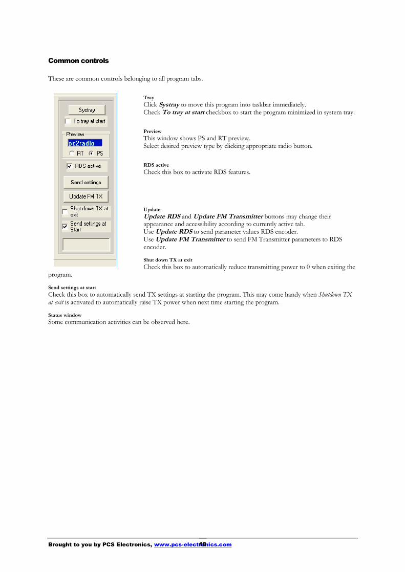
Common controls
These are common controls belonging to all program tabs.
TrayClick Systray to move this program into taskbar immediately.Check To tray at start checkbox to start the program minimized in system tray.
PreviewThis window shows PS and RT preview.Select desired preview type by clicking appropriate radio button.
RDS activeCheck this box to activate RDS features.
UpdateUpdate RDS and Update FM Transmitter buttons may change theirappearance and accessibility according to currently active tab.Use Update RDS to send parameter values RDS encoder.Use Update FM Transmitter to send FM Transmitter parameters to RDSencoder.
Shut down TX at exitCheck this box to automatically reduce transmitting power to 0 when exiting the
program.
Send settings at startCheck this box to automatically send TX settings at starting the program. This may come handy when Shutdown TXat exit is activated to automatically raise TX power when next time starting the program.
Status windowSome communication activities can be observed here.

Brought to you by PCS Electronics, www.pcs-electronics.com19
Scheduler
Built-in scheduler allows to user determine automatic switching of transmitting power and frequency according topredefined scheme. Schemes can be defined on daily or weekly basis. To accomplish this task the PC must beconnected to the transmitter and the program must be running all the time.Up to 20 controlling lines can be entered into list box. Each line defines transmitting power, frequency and switchingtime.Put a tick at the beggining of each line to make that line active. There can be many lines active if desired.It is recommended to be careful while entering lines not to make time-overlapping lines active at the same time.Example: if you define a line on daily basis and at the same time another weekly based line is active the results maybe unpredictable.You can always enter many lines and then decide which of them should be momentarily active by putting ticks intocheckboxes.
EnableCheck this box to make the scheduler active in general.
Add...Click Add... button to open Add form to add a new line into list box.
EditSelect desired line first, then click Edit to open Edit form.
RemoveSelect desired line first, then click Remove to delete it.

Brought to you by PCS Electronics, www.pcs-electronics.com20
Add form
Add form allows you to enter the following parameters:transmitter frequency transmitter power repetition mode; it can be Daily or Weekly switching timeDaily repetition mode switches every day at the same time. To make sense, at least two daily based lines should beactive at the same time.Weekly repetition mode allows individually selection of days in the week.
Add or ModifyClick this button to accept changes. In the case of adding lines more lines can be entered subsequently.
Close or CancelClick this button to finish adding lines or to cancel editing.

Brought to you by PCS Electronics, www.pcs-electronics.com21
TroubleshootingWe hope you’ll never get to this step. We all know bad things happen but do not despair! MAX PRO 4025+ is protectedwith a fuse, SWR and TEMP protection. Fuse is the first thing to check. Make sure your coaxial cable leading to thetransmitter or antenna is not shorted or open. Next check the troubleshooting table on the next page. If you have problemsyou cannot solve yourself, please see our website for contact information and support resources in our forum.
Fig 17: So, do you think you can handle it? We think you sure can!
Chapter
6

Brought to you by PCS Electronics, www.pcs-electronics.com22
PROBLEM DESCRIPTION POSSIBLE SOLUTIONS
USB device not recognized 1. Make sure to plug-in power connector at the back of the card, the one thataccepts PC hard disk or CD rom power jack.
Unable to control the card 1. Set the ports correctly, see appendix section below.
Audio without any treble Set pre-emphasis to either 50uS or 75uS. In USA you should have 75uS set.
Signal is cutting out, the card isvery hot
Thermal protection can shut down the output stage. Some air flow across the finaltransistor is recommended, especially for 3W card.
Audio distortion on high peaks,for example on “s” sound.
Your audio input level is slightly too high, reduce input audio level slightly at youraudio source. Use some kind of HW or SW compressor to remove over-modulationpeaks.
There is HUM in audio - Move antenna as far away from the PC and any audio gear as possible
- Use digital audio streaming via USB
- Keep audio cables short and away from antenna and RF coaxial cable
Output power less than expected Note the value shown by Windows software is not particularly accurate, it can showtoo much or too little. The accuracy depends on the impedance of the antenna andespecially the small portable type is not accurately matched to 50 ohms so take thepower readings with a grain of salt.
Output power less than expected If unit is overheating it will start reducing output power, make sure it is sufficientlycooled!

Brought to you by PCS Electronics, www.pcs-electronics.com23
Appendix A: DIY antenna and improvement tipsSimple GP antenna designYou can build an inexpensive 1/4 wave antenna from 1 so-239 chassis mount rf connector and 5 - 3' bronze welding rods,cut to the proper length. Here is how it looks:
Fig. 18: »Do it yourself« GP antenna
For other antenna designs check our web site here: http://www.pcs-electronics.com/guide_antenna.php
Some more improvement tipsThink about purchasing SWR meter to tune and align your antenna. A good antenna system is extremely important and canmake up for a lot of power. For a suitable SWR meter check:
http://www.pcs-electronics.com/cn101l-daiwa-power-meter-p-347.html
If you can’t get much range with your homebrew antenna, have a look at these:http://www.pcs-electronics.com/antennas-c-38.html
Still not enough range? Well, how about a 750W amplifier?http://www.pcs-electronics.com/750w-digital-amplifier-19inch-rack-p-1295.html
Appendix
AIf you have a SWR meter,leave a bit longer radiatorand adjust it later bycutting to achieveminimum SWR.
Most designs on the web don't compensate for the factthat GP antennas are not wideband antennas. Here is aFreq/element length chart for this simple GP antenna, allelement lengths are in millimeters:
Frequency Radiator - B Radials - A108MHZ 660mm 693mm104MHz 684mm 720mm100MHz 713mm 749mm90MHz 792mm 819mm

Brought to you by PCS Electronics, www.pcs-electronics.com24
Appendix B – USB port softwareNeeded filesThis manual and all necessary files can be found here: http://www.pcs-electronics.com/phpBB2/viewtopic.php?t=2409
Installing the USB driverUnzip the archive_usb2comport_driver.zip (there is also version for Win7-64) that you downloaded off our websitementioned above. Now run the downloaded and unpacked exe file. Wait for the following screen to appear and select theinstallation directory (best left alone at default location). Click Install and wait for the installation to finish. This dialog maydiffer slightly.
Fig. 26: Installing USB driver
Configuring USB driverIn Windows go to Start > Settings > Control Panel > System > Hardware tab > Device Manager (This can vary dependingon your Windows version). You should have something like this on your screen at this point:
Fig. 27: Configuring Com port for USB driver in Windows XP
Appendix
B

Brought to you by PCS Electronics, www.pcs-electronics.com25
Take note of the COM port number here, you will need it later to configure the COM port inside CyberMaxFM+ windowscontrol program. In Windows7 procedure differs slightly. Click on Start then "Devices and Printers" and you should seesomething like the following:
Fig. 28: Configuring Com port for USB driver in Windows7, note COM4 in the left bottom.
Note that the Silicon Labs CP210x USB to UART Bridge is utilizing COM4 in this example. You will need to know this inorder to complete the setup of the CyberMicroMax controller. If you wish to change this port for some reason right click onthe PCS USB-COM or Silicon Labs port (depending on selected driver) and select Properties. Now select the Port settingstab and click Advanced. Note you can set the COM port number as you wish:
Fig. 29: Configuring Com port for USB driver

Brought to you by PCS Electronics, www.pcs-electronics.com26
Configuring Windows control program
The only setup required is minimal. Start the CyberMaxMicroV40 program, the icon should now be on the desktop (phototaken from v30).
Now press File and Setup to bring-up this dialog:
You can set COM port manually or you can use Scan ports feature (recommended). Make sure FM Transmitter is turnedOn! A short guide for manual settings: If you are using USB make sure to set COM port to 5! When using RS232 please setCOM port to 1 or 2. These settings are usually correct. You can use Communication test tool to approve the selected COMport. Previous pages explain the installation and setup process for USB control cable.
Configuring audio playbackYou can either feed the audio to the card via the 3,5” stereo analog socket at the back or you can stream it digitally via USB.The PCIMAX card will appear as an additional “USB sound card” on your PC. If you wish you can set this sound card asdefault which will direct all PC audio to this sound card and it will be audible on the air and in your radio receivers. On theother hand you can configure your audio players to output audio to this particular sound card (USB Sound Card). Practicallyall audio playback programs will let you select audio device.

Brought to you by PCS Electronics, www.pcs-electronics.com27
Appendix C: General tips for setting up transmittersTypical FM transmitter setupsBelow are several of the typical broadcasting systems that can be encountered worldwide.
Fig. 25: Typical broadcasting systems
Lets look at system A first. It consists of audio source (mixer, microphones, CD players and a PC), FM exciter withintegrated RDS and stereo encoder (such as our CyberMaxFM+ units from 15W-300W) and antenna. Note antenna in thissystem is located in the same location as the transmitter and studio, typically it would be placed on a small tower or a pole atthe top of the building with studio. Disadvantage of this system is that you have to keep studio, transmitter and antennaclose. Now you usually can’t place studio on the top of a mountain for practical reasons so this limits your range. This is atypical small community radio with output powers of up to 300-500W.
System B is very similar to system A, but operators have decided to add an additional amplifier to boost the range. Suchstations can go into kilowatts, but they are starting to hit another speed limit. Since the studio is typically located in a town,high RF powers aren’t desirable due to interference with other services and safety regulations. So range is still limitedcompared to system C stations.
System C is radically different in one respect. Antenna and transmitter are no longer located at the same place with thestudio. To accomplish this the two audio channels are first combined with stereo processor. Resulting MPX signal is thanpassed to the STL wireless link transmitter (STL=Studio Transmitter Link). Up in the mountains is a STL wireless linkreceiver that receives the signal from the studio and passes I to the exciter. In this case exciter does not need to be stereoanymore since composite MPX signal is passed to its MPX input (all mono transmitters have this input). Such exciters canthan optionally drive big amplifiers with powers going into tens of KW with maximum range.
You can check our amplifiers here: http://www.pcs-electronics.com/fm-amplifiers-c-41.html
You can check our wireless STL links here: http://www.pcs-electronics.com/wireless-audio-links-c-42.html
Appendix
C

Brought to you by PCS Electronics, www.pcs-electronics.com28
Typical FM broadcasting antenna setupsBelow are several of the typical broadcasting antenna systems that can be encountered worldwide.
Fig. 26: Typical antenna setups
Lets look at system A first. It’s a simple vertical dipole antenna, mounted on a pole. The gain of this antenna is 0dBd and ifwe assume that the coaxial cable does not have any losses the ERP of this system equals transmitter power. For example, a1KW transmitter with this antenna system and perfect coaxial cable (losses=0) would have ERP of 1000W. Radiationpattern of this system is more-less omni-directional but since the metal pole holding the antenna blocks the signal there is anull of signal exactly on the opposite side of the pole.
System B has two simple dipole antennas mounted on a pole. The gain of this antenna is slightly less than 3dBd (due tolosses in harness – splitter). If we assume that the coaxial cable does not have any losses the ERP of this system equalsdouble transmitter power. For example, a 1KW transmitter with this antenna system and perfect coaxial cable (losses=0)would have ERP of 2000W. Note the antennas are mounted on the opposite sides of the pole to help make radiation patternas omni-directional as possible.
System C has four simple vertical dipole antennas mounted on a pole. One of the antennas is behind the pole and is notvisible. Note the antennas are mounted at an angle of 90 degrees between each other to help make radiation pattern as omni-directional as possible. The gain of this antenna is slightly less than 6dBd (due to losses in harness – splitter). If we assumethat the coaxial cable does not have any losses the ERP of this system equals 4x transmitter power. For example, a 1KWtransmitter with this antenna system and perfect coaxial cable (losses=0) would have ERP of 4000W.
System C has theoretically double the range of the System A although in practice it takes 4-6x increase of power to doublethe range. 4x increase of power is equal to 6dB of gain. And you get 3dB of gain by doubling the number of dipoles. So toupgrade system C to 9dBd you’d need 8 dipoles. And for 12dBd you’d need 16 dipoles. 16 dipoles would in theory increaseyour range 4x compared to a single dipole. In practice there would be some losses in combining so many dipoles. You canuse circular dipoles in very similar configurations.

Brought to you by PCS Electronics, www.pcs-electronics.com29
Wiring antennas in multi-bay configurationsWe have observed typical multi-dipole (called multi-bay) antenna configurations on the previous page. However there aresome things to keep in mind.
Fig. 27: Wiring multi-bay antennas
Look at the diagram above. This is a simple system with two dipole antennas and a 2-way coaxial splitter (harness). Thissplitter is made from sections of coaxial cable with such impedance and length which ensure perfect match at specificfrequency. Do not attempt to assemble from regular 50-ohm coaxial cable. What is important here is that the two sections ofcoaxial cable going from antenna to the splitter should be of exact equal length. These two sections are shown in black. Thesame rule applies for system with more dipoles. It is also possible to have cables of different lengths, but you have to knowvelocity factor of the cable so we have omitted this for simplicity reasons. If you want more info please contact our technicalstaff.
Brought to you by PCS Electronics, www.pcs-electronics.com30
Appendix D: Communication protocol explanationIf you are one of the many interested in developing your own RDSMAX application, look no further. The entireprotocol will be explained here in detail. Also check the provided sample VB application. If you’re still stuck, dodrop us an email and we will be more than happy to help you out.
Baud rate and COM portCommunication with RDSMAX 4000+ uses RS232 protocol. There are 4 supported speeds, 2400, 14400, 19200 and38400. 2400 was provided for extremely long cable runs, 14400 was used for compatibility with RDSMAX 30, 19200and 38400 were added for cases where fast update time is an advantage.
A simple VB code would look like this: MSComm1.CommPort = COMSelected 'This can be COM1, COM2 etc Select Case COMSpeed Case 1 MSComm1.Settings = "2400,N,8,1" Case 2 MSComm1.Settings = "14400,N,8,1" Case 3 MSComm1.Settings = "19200,N,8,1" Case 4 MSComm1.Settings = "38400,N,8,1" End Select MSComm1.InputLen = 0 MSComm1.PortOpen = True
General Command FormatThis is the format of a typical command sent to the RDSMAX encoder:<StartByte>Command<EndCommandByte>Value<EndByte>
<StartByte>: Signals start of new incoming command/parameterThe hey/binary value of this byte is 0x00 (0b00000000).VB basic example: MSComm1.Output = Chr$(0) 'Start (0)
Command: Command/parameter that you wish to send to the encoderSimply send the command/parameter in ASCII form.VB basic example: MSComm1.Output = "TA"
<EndCommandByte>: Signals end of the new incoming command, tells encoder to expect incomingcommand/parameter valueThe hey/binary value of this byte is 0x01 (0b00000001).VB basic example: MSComm1.Output = Chr$(1) ‘End Command start of value(1)
Value: Command/parameter value that you wish to send to the encoderThe method varies a bit from parameter to parameter, but usually you can simply send the command/parametervalue in ASCII form. Check each parameter individually for correct setting.VB basic example: MSComm1.Output = "1" 'sets TA to ON
<EndByte>: Signals the end of complete incoming command including command/parameter value, it tells encoderto process the received dataVB basic example: MSComm1.Output = Chr$(2) ‘End Command and value
Appendix
D

Brought to you by PCS Electronics, www.pcs-electronics.com31
PSThis is the most interesting feature for 99% of customers out there so we will dedicate a bit more time to it. RDSstandard provides for a 8-character PS string which is used to identify radio station and is displayed by RDS-enabledradio receivers. Some countries prohibit changing this text dynamically, but others don’t. Whatever your decisionmay be, RDSMAX supports either static or dynamic PS. It is best to check with the local authorities before settingup the RDS encoder.The mechanism for handling dynamic (or static) PS text is best demonstrated by the following example:Imagine a train traveling in a round trip involving 100 train stations. The train starts on station 00 (PS00) and goesthrough stations 01, 02…. until it passes through station 99 and finally returns to station 00. Every time a train stopsat the station it sends the message back to the headquoters (PS text shown on RDS receiver). The amount of timethe train stays at the station (delay – PD00 to PD99) varies and can be from 0 minutes (train does not stop) to 9minutes. I hope this little analogy has illustrated the process. You have 100 8-character strings (PS00 to PS99) whichare displayed one after the other until the entire loop repeats itself. You can define how long each of these strings isdisplayed, the parameter which defines this is PD (PD00 to PD99).
Example: If you wish to just have one static PS, set all delays to 0 and set just PD00 to 1. Than set PS00 to desiredstatis PS, which will be displayed indefinitely.
General Command FormatThis is the format of a PS00 command, which sets PS00 to **TEST**:<StartByte>PS00<EndCommandByte>**TEST**<EndByte>
VB basic example:MSComm1.Output = Chr$(0) 'Start (0)MSComm1.Output = "PS00"MSComm1.Output = Chr$(1) ‘End Command start of value(1)MSComm1.Output = "**TEST**"MSComm1.Output = Chr$(2) ‘End Command and value
This is the format of a PD00 command, which sets PD00 to 5:<StartByte>PD00<EndCommandByte>5<EndByte>
VB basic example:MSComm1.Output = Chr$(0) 'Start (0)MSComm1.Output = "PD00"MSComm1.Output = Chr$(1) ‘End Command start of value(1)MSComm1.Output = "5"MSComm1.Output = Chr$(2) ‘End Command and value
It is recommended to put a short delay of 10ms after sending of each data packet. So the example above becomes:
MSComm1.Output = Chr$(0) 'Start (0)Sleep 10MSComm1.Output = "PD00"Sleep 10MSComm1.Output = Chr$(1) ‘End Command start of value(1)Sleep 10MSComm1.Output = "5"Sleep 10MSComm1.Output = Chr$(2) ‘End Command and valueSleep 10
RTThis is another popular feature, RDS allows for 64-character text string to be displayed on the receiver. However thisfeature is rarely used as you need to press a button to display it (PS is always displayed by default). Another “nail inRTs' coffin" is the fact that typical receiver only displays a maximum of 8-characters at a time meaning the messageneeds to be scrolled. However popular or unpopular it may be, we support it.
General Command Format

Brought to you by PCS Electronics, www.pcs-electronics.com32
This is the format of a PS00 command, which sets PS00 to **TEST**:<StartByte>RT<EndCommandByte>**THIS IS A TEST OF RADIO TEXT FEATURE**<EndByte>
VB basic example:MSComm1.Output = Chr$(0) 'Start (0)MSComm1.Output = "RT"MSComm1.Output = Chr$(1) ‘End Command start of value(1)MSComm1.Output = "**THIS IS A TEST OF RADIO TEXT FEATURE**"MSComm1.Output = Chr$(2) ‘End Command and value
Format descriptions for the other supported parameters:
‘Sending TPMSComm1.Output = Chr$(0) 'Start (0)MSComm1.Output = "TP"MSComm1.Output = Chr$(1) 'End command and start of data (1)temp = Str$(TP)temp = LTrim(temp)MSComm1.Output = temp
'Sending STEREO/MONO statusMSComm1.Output = Chr$(0) 'Start (0)MSComm1.Output = Chr$(0) 'Start (0)MSComm1.Output = "FS"MSComm1.Output = Chr$(1) 'End command and start of data (1)temp = Str$(TXStereo)temp = LTrim(temp)MSComm1.Output = tempMSComm1.Output = Chr$(2) 'Finish command
'Sending RDS active (PWR)MSComm1.Output = Chr$(0) 'Start (0)MSComm1.Output = "PWR" 'Program reference, lower byte of PIMSComm1.Output = Chr$(1) 'End command and start of data (1)If Check1.Value = 1 Thentemp = "1" 'turn RDS onElsetemp = "0" 'turn RDS offEnd IfMSComm1.Output = tempMSComm1.Output = Chr$(2) 'Finished transmission
'Sending CCACMSComm1.Output = Chr$(0) 'Start (0)MSComm1.Output = "CCAC" 'Program reference, lower byte of PIMSComm1.Output = Chr$(1) 'End command and start of data (1)temp = Str$(CountryCode * 16 + AreaCoverage)temp = LTrim(temp)If Len(temp) = 2 Then temp = "0" & tempIf Len(temp) = 1 Then temp = "00" & tempIf Len(temp) = 0 Then temp = "000"MSComm1.Output = tempMSComm1.Output = Chr$(2) 'Finished transmission
'Sending ProgReferenceMSComm1.Output = Chr$(0) 'Start (0)MSComm1.Output = "PREF" 'Program reference, lower byte of PIMSComm1.Output = Chr$(1) 'End command and start of data (1)temp = Str$(ProgramReference)temp = LTrim(temp)If Len(temp) = 2 Then temp = "0" & tempIf Len(temp) = 1 Then temp = "00" & tempIf Len(temp) = 0 Then temp = "000"MSComm1.Output = tempMSComm1.Output = Chr$(2) 'Finished transmission
'Sending PTYMSComm1.Output = Chr$(0) 'Start (0)MSComm1.Output = "PTY"MSComm1.Output = Chr$(1) 'End command and start of data (1)temp = Str$(PTY)temp = LTrim(temp)If Len(temp) = 1 Then temp = "0" & tempIf Len(temp) = 0 Then temp = "00"MSComm1.Output = temp

Brought to you by PCS Electronics, www.pcs-electronics.com33
'Sending TPMSComm1.Output = Chr$(0) 'Start (0)MSComm1.Output = "TP"MSComm1.Output = Chr$(1) 'End command and start of data (1)temp = Str$(TP)temp = LTrim(temp)MSComm1.Output = temp
'Sending TAMSComm1.Output = Chr$(0) 'Start (0)MSComm1.Output = "TA"MSComm1.Output = Chr$(1) 'End command and start of data (1)temp = Str$(TA)temp = LTrim(temp)MSComm1.Output = tempMSComm1.Output = Chr$(2) 'Finish command
'Sending MSMSComm1.Output = Chr$(0) 'Start (0)MSComm1.Output = "MS"MSComm1.Output = Chr$(1) 'End command and start of data (1)temp = Str$(MS)temp = LTrim(temp)MSComm1.Output = tempMSComm1.Output = Chr$(2) 'Finish command
'Sending Did0MSComm1.Output = Chr$(0) 'Start (0)MSComm1.Output = "Did0"MSComm1.Output = Chr$(1) 'End command and start of data (1)temp = Str$(DId0)temp = LTrim(temp)MSComm1.Output = tempMSComm1.Output = Chr$(2) 'Finish command
'Sending AF0 (af number)MSComm1.Output = Chr$(0) 'Start (0)MSComm1.Output = "AF0"MSComm1.Output = Chr$(1) 'End command and start of data (1)temp = Chr$(AFNum + 224 + 4)MSComm1.Output = tempMSComm1.Output = Chr$(2) 'Finish command
'Sending AF1MSComm1.Output = Chr$(0) 'Start (0)MSComm1.Output = "AF1"MSComm1.Output = Chr$(1) 'End command and start of data (1)temp = Chr$(AF1 + 4)MSComm1.Output = tempMSComm1.Output = Chr$(2) 'Finish command
'Sending RTMSComm1.Output = Chr$(0) 'Start (0)MSComm1.Output = "RT"MSComm1.Output = Chr$(1) 'End command and start of data (1)temp = RT & Chr$(13) & Chr$(13) & String(64, Chr(13))If Len(temp) > 64 Then temp = Left(temp, 64)MSComm1.Output = temp 'RTMSComm1.Output = Chr$(2) 'Finish command
'Send PSMSComm1.Output = Chr$(0) 'Start (0)MSComm1.Output = "PS00"MSComm1.Output = Chr$(1) 'End command and start of data (1)temp = “your text”MSComm1.Output = tempMSComm1.Output = Chr$(2) 'Finish command
'Sending ECCMSComm1.Output = Chr$(0) 'Start (0)MSComm1.Output = "ECC"MSComm1.Output = Chr$(1) 'End command and start of data (1)temp = Chr$(ECC + 4)MSComm1.Output = tempMSComm1.Output = Chr$(2) 'Finish command

Brought to you by PCS Electronics, www.pcs-electronics.com34
'Sending RF POWER statusMSComm1.Output = Chr$(0) 'Start (0)MSComm1.Output = "FO"MSComm1.Output = Chr$(1) 'End command and start of data (1)If Option25(13).Value = True Then ‘check versiontemp = Chr$((Int(TXPower / 100 * 34)) + 4) 'was 100*20 for max pro 4025 v3Elsetemp = Chr$((Int(TXPower / 100 * 44)) + 4) 'was 100*20 for max pro 4025 v4End IfMSComm1.Output = tempMSComm1.Output = Chr$(2) 'Finish command
'Sending FrequencyMSComm1.Output = Chr$(0) 'Start (0)MSComm1.Output = "FF"MSComm1.Output = Chr$(1) 'End command and start of data (1)temp = Chr$((Int(TXFrequency / 5) - Int(Int(TXFrequency / 5) / 128) * 128) + 4) 'low part of freqtemp = temp & Chr$((Int(Int(TXFrequency / 5) / 128)) + 4) 'high part of freqMSComm1.Output = tempMSComm1.Output = Chr$(2) 'Finish command
'Sending DSP settings - TrebleMSComm1.Output = Chr$(0) 'Start (0)MSComm1.Output = "FDT"MSComm1.Output = Chr$(1) 'End command and start of data (1)MSComm1.Output = Chr$(Treble + 4)MSComm1.Output = Chr$(2) 'Finish command
'Sending DSP settings - BassMSComm1.Output = Chr$(0) 'Start (0)MSComm1.Output = "FDB"MSComm1.Output = Chr$(1) 'End command and start of data (1)MSComm1.Output = Chr$(Bass + 4)MSComm1.Output = Chr$(2) 'Finish command
'Sending DSP settings - AttackMSComm1.Output = Chr$(0) 'Start (0)MSComm1.Output = "FDA"MSComm1.Output = Chr$(1) 'End command and start of data (1)MSComm1.Output = Chr$(Attack + 4)MSComm1.Output = Chr$(2) 'Finish command
'Sending DSP settings - DecayMSComm1.Output = Chr$(0) 'Start (0)MSComm1.Output = "FDD"MSComm1.Output = Chr$(1) 'End command and start of data (1)MSComm1.Output = Chr$(Decay + 4)MSComm1.Output = Chr$(2) 'Finish command
'Sending DSP settings - ThresholdMSComm1.Output = Chr$(0) 'Start (0)MSComm1.Output = "FDH"MSComm1.Output = Chr$(1) 'End command and start of data (1)MSComm1.Output = Chr$(Threshold + 4)MSComm1.Output = Chr$(2) 'Finish command
'Sending DSP settings - CompressionMSComm1.Output = Chr$(0) 'Start (0)MSComm1.Output = "FDC"MSComm1.Output = Chr$(1) 'End command and start of data (1)MSComm1.Output = Chr$(Compression + 4)MSComm1.Output = Chr$(2) 'Finish command
'Sending DSP settings - IntegrationMSComm1.Output = Chr$(0) 'Start (0)MSComm1.Output = "FDI"MSComm1.Output = Chr$(1) 'End command and start of data (1)MSComm1.Output = Chr$(Integration + 4)MSComm1.Output = Chr$(2) 'Finish command
'Sending DSP settings - LeftGainMSComm1.Output = Chr$(0) 'Start (0)MSComm1.Output = "FDGL"MSComm1.Output = Chr$(1) 'End command and start of data (1)MSComm1.Output = Chr$(LeftGain + 4)MSComm1.Output = Chr$(2) 'Finish command

Brought to you by PCS Electronics, www.pcs-electronics.com35
'Sending DSP settings - RightGainMSComm1.Output = Chr$(0) 'Start (0)MSComm1.Output = "FDGR"MSComm1.Output = Chr$(1) 'End command and start of data (1)MSComm1.Output = Chr$(RightGain + 4)MSComm1.Output = Chr$(2) 'Finish command
'Sending settings - TEMP alarmMSComm1.Output = Chr$(0) 'Start (0)MSComm1.Output = "FAT"MSComm1.Output = Chr$(1) 'End command and start of data (1)MSComm1.Output = Chr$(TEMPAlarm + 4)MSComm1.Output = Chr$(2) 'Finish command
'Sending settings - SWR alarmMSComm1.Output = Chr$(0) 'Start (0)MSComm1.Output = "FAS"MSComm1.Output = Chr$(1) 'End command and start of data (1)MSComm1.Output = Chr$(SWRAlarm + 4)MSComm1.Output = Chr$(2) 'Finish command
'Sending settings - Uamp alarmMSComm1.Output = Chr$(0) 'Start (0)MSComm1.Output = "FAU"MSComm1.Output = Chr$(1) 'End command and start of data (1)MSComm1.Output = Chr$(UampAlarm + 4)MSComm1.Output = Chr$(2) 'Finish command
'Sending settings - Iamp alarmMSComm1.Output = Chr$(0) 'Start (0)MSComm1.Output = "FAC"MSComm1.Output = Chr$(1) 'End command and start of data (1)MSComm1.Output = Chr$(IampAlarm + 4)MSComm1.Output = Chr$(2) 'Finish command
'Sending Store command, commits changesMSComm1.Output = Chr$(0) 'Start (0)MSComm1.Output = "FW"MSComm1.Output = Chr$(1) 'End command and start of data (1)temp = 0MSComm1.Output = tempMSComm1.Output = Chr$(2) 'Finish command

Brought to you by PCS Electronics, www.pcs-electronics.com36
Appendix D – Warranty and legal info
Important notice!Please remember to turn off the transmitter/amplifier when not in use! This goes especially for high poweredtransmitters. Remember that anything you broadcast through the transmitter can be heard by anyone tuning in to thatfrequency. Although it is unlikely certain weather conditions may allow the signal to go further than your immediate listeningarea so please don't broadcast anything you don't mind anyone else hearing.
Warranty and servicing!Within one (1) year of receiving your order, if any product proves to be defective; please contact us via e-mail or ourfeedback form. Please DO NOT ship the product back to us without contacting us first and receiving return instructions.After we receive the defective merchandise, we will test it if need be, and we will ship back to you a non-defectivereplacement product. Please note that this doesn't cover final RF transistor as it can be damaged by using defective or poorlymatched antenna. An exception is as well any mishandling or abuse by the customer. If the product is defective, you willreceive a replacement. If you choose to return the defective item, rather than replace it, we will charge a 20% restocking feeand your original shipping and handling charges will not be refunded. The return of the product is at your expense. Webelieve that this is a fair policy because lower overhead results in lower prices for all of our customers.
Legal infoIt may be illegal to operate this device in your county. Please consult local authorities before using our products! PCSElektronik d.o.o. is not responsible for any damage to your PC arising from use of this product and will not be heldresponsible for any violation of local laws pertaining to the use of this product. It is entirely your responsibility that you makesure you operate in accordance with local laws and/or regulations.
Limitation of liabilityTo the law, in no event shall PCS Elektronik d.o.o. or its suppliers be liable for any special, incidental, indirect, orconsequential damages whatsoever (including, without limitation, damages for loss of business profits, business interruption,loss of business information, or any other pecuniary loss) arising out of the use of or inability to use the PRODUCT, even ifPCS Elektronik d.o.o. has been advised of the possibility of such damages. In any case, PCS Elektronik d.o.o.´s entireliability under any provision of this agreement shall be limited to the greater of the amount actually paid by you for thePRODUCT or U.S. $5.00; because some states and jurisdictions do not allow the exclusion or limitation of liability, theabove limitation may not apply to you.
Appendix
E

Brought to you by PCS Electronics, www.pcs-electronics.com37
Also available from www.pcs-electronics.comWe also carry a big range of:
- FM transmitters in assembled and KIT form- TV transmitters in assembled and KIT form, VHF and UHF- AM transmitters with extremely clear modulation (PWM design)- Various accessories for professional and hobby FM radio stations- A large assortment of hard to obtain RF components (RF transistors; MRF, 2SC, coils, silver plated wire, coaxial cable,capacitors, quartz crystals and many others)- PC based FM transmitters (PCI MAX pc based FM transmitter turns your PC into a radio station)- A large number of beginners guides to get you started- A large selection of free schematics is as well available at our website.
If you can’t get much range with your homebrew antenna, have a look at these: http://www.pcs-electronics.com

Brought to you by PCS Electronics, www.pcs-electronics.com38
Revisions and errataV1.0 (February 2010): Release version
V1.1 (Jan 2013): Fixed software installation
Please report any errors you see in this manual, you will be helping us and many other users out there. Thank you!
IndexA
adjusting.............................................................. 8Antenna............................................................... 8
B
beam.................................................................... 8board layout......................................................... 6
C
Coaxial cable ....................................................... 9
D
directional antenna............................................... 8
F
feedback .............................................................. 8final transistor...................................................... 8
G
gain ..................................................................... 8grounding ............................................................ 8
H
H-500 .................................................................. 9
M
mains cable .......................................................... 9mains power supply.............................................. 9metal case ............................................................ 8
O
omni-directional antenna...................................... 8
P
PCIMAX3000+ ................................................... 4perfect match ....................................................... 9
R
radiation pattern ................................................... 8RF shielded.......................................................... 8RG-58.................................................................. 9
S
short circuit.......................................................... 8SWR................................................................ 8, 9
T
Technical specifications ....................................... 5Troubleshooting................................................. 13tune ..................................................................... 8