Embed Size (px)
Citation preview
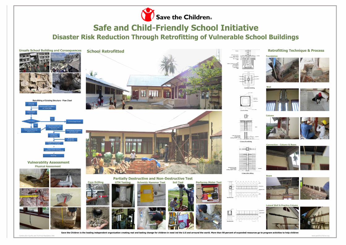
MANUAL ON
“RETROFITTING OF EXISTING VULNERABLE
SCHOOL BUILDINGS – ASSESSMENT TO RETROFITTING”
PART I
Hari Darshan Shrestha
Krishna S. Pribadi
Dyah Kusumastuti
Edwin Lim
Mission of Save the Children
To create lasting, positive change in the lives of children in need
Vision of Save the Children
A world in which every child is ensured the right to survival, protection, development and participation as set forth in the United Nations Convention on the Right of Children
This book is developed by Save the Children, Construction Quality & Technical Assistance (CQTA)
in collaboration with
Center for Disaster Mitigation - Institute of Technology Bandung (CDM -ITB)


Manual on ”Retrofitting of Existing Vulnerable School Buildings-Assessment to Retrofitting” Part I
i
PREFACE
Schools are institutions providing an education as well as a common place for community
gatherings and meetings. They should be models in providing examples of quality education and the
enhancement of the environment & physical facilities. Schools not only provide opportunities for
formal education, but also for social development and personal growth.
Despite this, there are millions of schools around the world that are unsafe. There is an urgent need
to create greater awareness of safer school construction in new schools, while at the same time
making sure that the existing school buildings are safe. This can be done through the implementation
of general practices of safe school construction and the retrofitting of existing school buildings.
Creating a culture of safe school construction is possible and need not be as complicated as some
may seem. It can be implemented simply by establishing standards of design and construction of
school buildings, developing a local building code and ensuring that the code and standards are met.
The challenge is the thousands of unsafe existing school buildings around the globe where millions of
children are at risk. Recent disasters such as the earthquake in Pakistan and China, the cyclone in
Bangladesh and the infamous hurricane Katrina in the USA have caused the destruction of thousands
of schools and with them the lives of many students and teachers. This shows the urgent need to
make schools safer for everyone.
Save the Children initiated the creation of safe and child friendly school construction. Save the
Children is conducting workshops and trainings as well as developing guidelines and manuals to
support this initiative.
These documents are based on best practices in Indonesia, the most seismic prone country in the
world. We believe these resources could be useful for other countries facing similar challenges as well
as other organizations working on building the capacities of local authorities to effectively implement
safe and child friendly school buildings.
We would like to thank Dr. Krishna Pribadi, Dr. Dyah Kusumastuti and Mr. Edwin Lim from the Center
for Disaster Mitigation - Institute of Technology Bandung, and Mr. Hari Darshan Shrestha for their
contributions on the development of this document.
Mike Novell
AVP, Asia Area office
Save the Children
Manual on ”Retrofitting of Existing Vulnerable School Buildings-Assessment to Retrofitting” Part I
ii
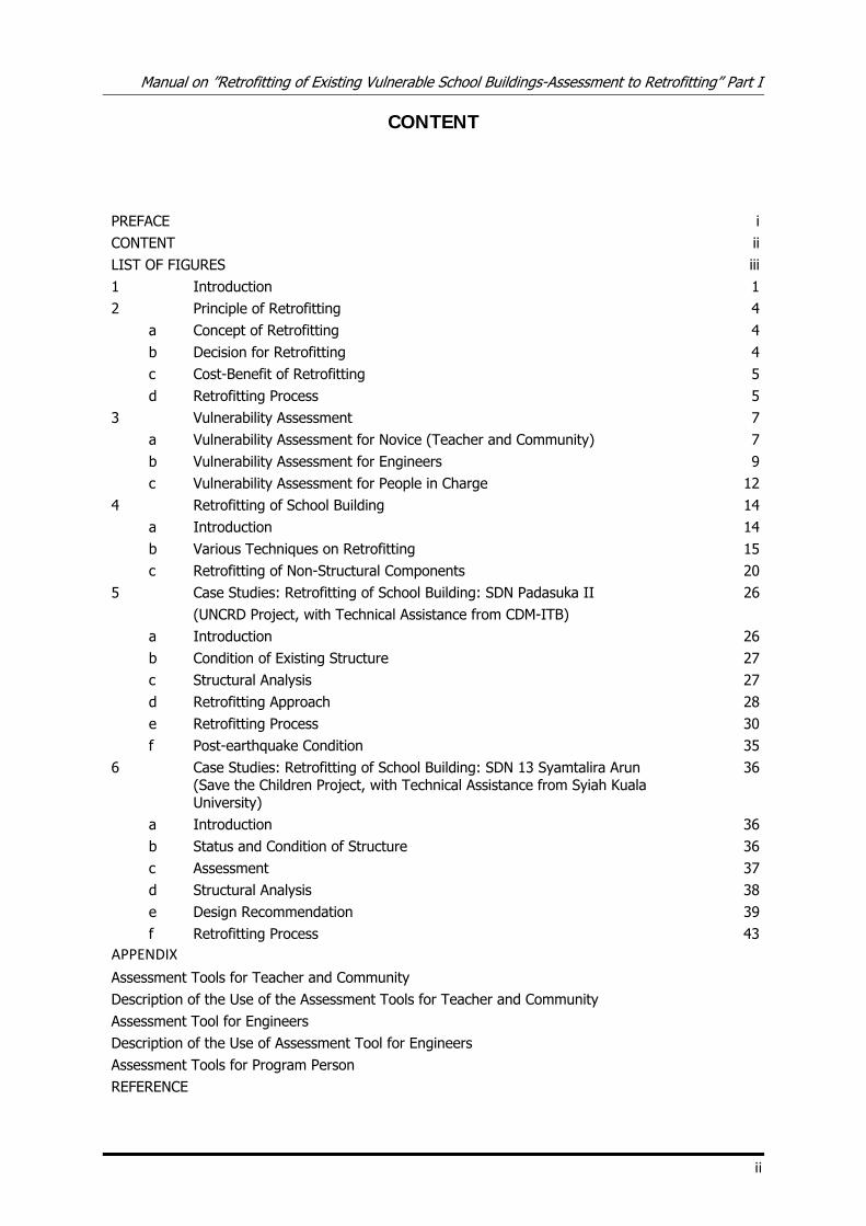
CONTENT
PREFACE iCONTENT iiLIST OF FIGURES iii1 Introduction 12 Principle of Retrofitting 4 a Concept of Retrofitting 4 b Decision for Retrofitting 4 c Cost-Benefit of Retrofitting 5 d Retrofitting Process 53 Vulnerability Assessment 7 a Vulnerability Assessment for Novice (Teacher and Community) 7 b Vulnerability Assessment for Engineers 9 c Vulnerability Assessment for People in Charge 124 Retrofitting of School Building 14 a Introduction 14 b Various Techniques on Retrofitting 15 c Retrofitting of Non-Structural Components 205 Case Studies: Retrofitting of School Building: SDN Padasuka II 26 (UNCRD Project, with Technical Assistance from CDM-ITB) a Introduction 26 b Condition of Existing Structure 27 c Structural Analysis 27 d Retrofitting Approach 28 e Retrofitting Process 30 f Post-earthquake Condition 356 Case Studies: Retrofitting of School Building: SDN 13 Syamtalira Arun 36
(Save the Children Project, with Technical Assistance from Syiah Kuala University)
a Introduction 36 b Status and Condition of Structure 36 c Assessment 37 d Structural Analysis 38 e Design Recommendation 39 f Retrofitting Process 43APPENDIX
Assessment Tools for Teacher and Community Description of the Use of the Assessment Tools for Teacher and Community Assessment Tool for Engineers Description of the Use of Assessment Tool for Engineers Assessment Tools for Program Person REFERENCE
Manual on ”Retrofitting of Existing Vulnerable School Buildings-Assessment to Retrofitting” Part I
iii
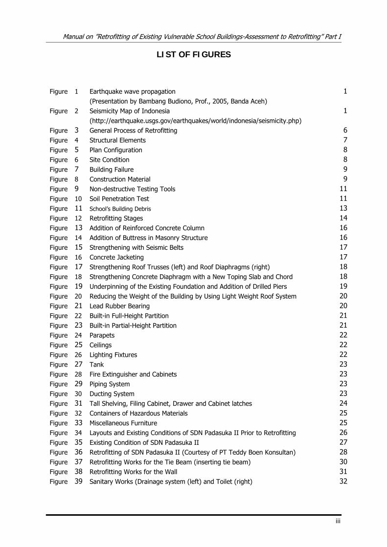
LIST OF FIGURES
Figure 1 Earthquake wave propagation 1 (Presentation by Bambang Budiono, Prof., 2005, Banda Aceh) Figure 2 Seismicity Map of Indonesia 1 (http://earthquake.usgs.gov/earthquakes/world/indonesia/seismicity.php) Figure 3 General Process of Retrofitting 6Figure 4 Structural Elements 7Figure 5 Plan Configuration 8Figure 6 Site Condition 8Figure 7 Building Failure 9Figure 8 Construction Material 9Figure 9 Non-destructive Testing Tools 11Figure 10 Soil Penetration Test 11Figure 11 School’s Building Debris 13Figure 12 Retrofitting Stages 14Figure 13 Addition of Reinforced Concrete Column 16Figure 14 Addition of Buttress in Masonry Structure 16Figure 15 Strengthening with Seismic Belts 17Figure 16 Concrete Jacketing 17Figure 17 Strengthening Roof Trusses (left) and Roof Diaphragms (right) 18Figure 18 Strengthening Concrete Diaphragm with a New Toping Slab and Chord 18Figure 19 Underpinning of the Existing Foundation and Addition of Drilled Piers 19Figure 20 Reducing the Weight of the Building by Using Light Weight Roof System 20Figure 21 Lead Rubber Bearing 20Figure 22 Built-in Full-Height Partition 21Figure 23 Built-in Partial-Height Partition 21Figure 24 Parapets 22Figure 25 Ceilings 22Figure 26 Lighting Fixtures 22Figure 27 Tank 23Figure 28 Fire Extinguisher and Cabinets 23Figure 29 Piping System 23Figure 30 Ducting System 23Figure 31 Tall Shelving, Filing Cabinet, Drawer and Cabinet latches 24Figure 32 Containers of Hazardous Materials 25Figure 33 Miscellaneous Furniture 25Figure 34 Layouts and Existing Conditions of SDN Padasuka II Prior to Retrofitting 26Figure 35 Existing Condition of SDN Padasuka II 27Figure 36 Retrofitting of SDN Padasuka II (Courtesy of PT Teddy Boen Konsultan) 28Figure 37 Retrofitting Works for the Tie Beam (inserting tie beam) 30Figure 38 Retrofitting Works for the Wall 31Figure 39 Sanitary Works (Drainage system (left) and Toilet (right) 32
Manual on ”Retrofitting of Existing Vulnerable School Buildings-Assessment to Retrofitting” Part I
iv
Figure 40 Retrofitting Works for the Trusses and Roof (Providing proper materials and detailing) 33
Figure 41 Finishing Works (Painting, Architectural gravel installation, etc) 33Figure 42 Retrofitting of SD Padasuka 2 34Figure 43 Post-earthquake Condition 35Figure 44 SDN 13 Syamtalira Arun Layout 36Figure 45 Existing Condition of SDN 13 Syamtalira Arun 36Figure 46 Visual Assessment 37Figure 47 Technical Assessment 38Figure 48 Retrofitting of Foundation 39Figure 49 Retrofitting of Beam 40Figure 50 Retrofitting of Column 41Figure 51 Retrofitting between Wall and Column 42Figure 52 Cracks Injection 42Figure 53 Retrofitting of Foundation 43Figure 54 Column Retrofitting 43Figure 55 Beam Retrofitting 44Figure 56 Retrofitted Structure 44
Manual on ”Retrofitting of Existing Vulnerable School Buildings-Assessment to Retrofitting” Part I
3
The solutions for mitigating earthquake hazard for school buildings are different for new buildings and
existing buildings, with respect to the challenges faced by each category. The common procedure for
earthquake mitigation of buildings is as follows:
a. For new buildings, the mitigation measures include the design and construction process. The
design of the buildings must comply with the current building code, and the construction must be
appropriate following design specifications and drawings.
b. For existing buildings, the mitigation measures consist of assessing the structural performance to
resist design earthquake forces based on current building codes. If the assessment found that
structures are not adequate, retrofitting strategies should be designed to improve the building’s
performance.
Manual on ”Retrofitting of Existing Vulnerable School Buildings-Assessment to Retrofitting” Part I
4
2. Principle of Retrofitting
a. Concept of Retrofitting
Retrofitting is technical interventions in structural system of a building that improve the resistance
to earthquake by optimizing the strength, ductility and earthquake loads. Strength of the building
is generated from the structural dimensions, materials, shape, and number of structural
elements, etc. Ductility of the building is generated from good detailing, materials used, degree of
seismic resistant, etc. Earthquake load is generated from the site seismicity, mass of the
structures, important of buildings, degree of seismic resistant, etc.
Due to the variety of structural condition of building, it is hard to develop typical rules for
retrofitting. Each building has different approaches depending on the structural deficiencies.
Hence, engineers are needed to prepare and design the retrofitting approaches.
In the design of retrofitting approach, the engineer must comply with the building codes. The
results generated by the adopted retrofitting techniques must fulfill the minimum requirements on
the buildings codes, such as deformation, detailing, strength, etc.
b. Decision for Retrofitting
Retrofitting is needed when the assessment of structural capacity results in insufficient capacity
to resist the forces of expected intensity and acceptable limit of damages.
It is not merely poor quality of materials and damage of structural elements serves as the
reasons to retrofit a building. Change of the building’s function, change of environmental
conditions, and change of valid building codes could also be the reasons for retrofitting.
Retrofitting must be conducted by experts from each field. In most retrofitting process, an
engineer plays the main role. An engineer must assess and analyze the structural capacity. An
engineer must also design the best retrofitting techniques to strengthen the structural
deficiencies. The role of the novice is restricted to identify the possibility of insufficiency of
building capacity.
Some factors that should be considered in order to decide whether to retrofit or not are:
a) Technical aspect
The technical aspects include the testing of materials and structural analysis. These measures
are important to understand the condition of the structures related to the recent building
codes.
b) Cost intervention
Cost and benefit analysis must be conducted before the decision is made. The next sub-
chapter will explain this issue further
c) Importance of building
Each building is built for its own purpose. Some old buildings have extra values, such as
historical values, that will strongly affect the final decision.
Manual on ”Retrofitting of Existing Vulnerable School Buildings-Assessment to Retrofitting” Part I
5
d) Availability of adequate technology
Some of retrofitting techniques need a “modern” technology to implement it. A decision of
retrofitting must consider whether the region provides such technology.
e) Skilled workmanship to implement the proposed measures
Some of retrofitting techniques need unusual construction method to implement it. A skilled
workmanship must be provided to implement the proposed measures.
f) Duration of works.
Some of retrofitting works will consume less time to finish it, but others take more time to
complete. Hence, it is important to take into the consideration the duration of works.
c. Cost-Benefit of Retrofitting
Cost-Benefit analysis is sometimes conducted to determine whether retrofit or rebuild the building
is more feasible. Most studies imply that retrofitting of an existing structure is more feasible than
to build a new building. Retrofitting is a also a favorable approach to strengthen the building
capacity to the external loads, e.g. earthquake. The advantages of adopting retrofitting approach,
despite of reconstructing the building, can be listed as follows:
a. When retrofitting approach is adopted, retrofitted building can still be operated.
b. Retrofitting will take relatively less construction cost with the same structural performance
achievement.
c. Retrofitting will involve relatively less resources, either human resources or natural resources.
d. Retrofitting will not significantly change the building configuration and shape. It is preferable
when the retrofitted building has historical values.
e. Retrofitting the building will produce less debris than reconstructing the building.
Besides the advantages, retrofitting also has several disadvantages as follows:
a. The skill of the worker must comply with the adopted retrofitting approaches.
b. Limited access of the construction site since the building could be still in function.
It is important to note that the analysis must consider all parameters that can affect the decision.
All costs and savings (including casualties and serviceability period) over a long period of time
should also be taken into account.
d. Retrofitting Process
The retrofitting of a structure involves improving its performance under earthquake loadings
through one or more of these following measures:
1) Increasing its strength and/or stiffness
2) Increasing its ductility
3) Reducing the seismic forces.
The measures can be done through modification to one or more of the following parameters:
Manual on ”Retrofitting of Existing Vulnerable School Buildings-Assessment to Retrofitting” Part I
6
1) Columns
2) Beams
3) Bracings
4) Walls
5) Foundation
6) Horizontal diaphragms
7) Joints between structural elements
8) Masses
9) Period of vibrations
When implementing these measures to buildings, it is importance that:
1) The buildings provide the required degree of seismic resistance
2) The chosen approaches are simple and economical to implement
It is important to note that the retrofitting of structural elements should not be conducted for
only an individual element or groups of elements. The good performance of the whole structural
system must be ensured. For example, when retrofitting is only conducted for some columns,
attention should be placed to prevent worsening distribution of earthquake forces in the structural
elements.
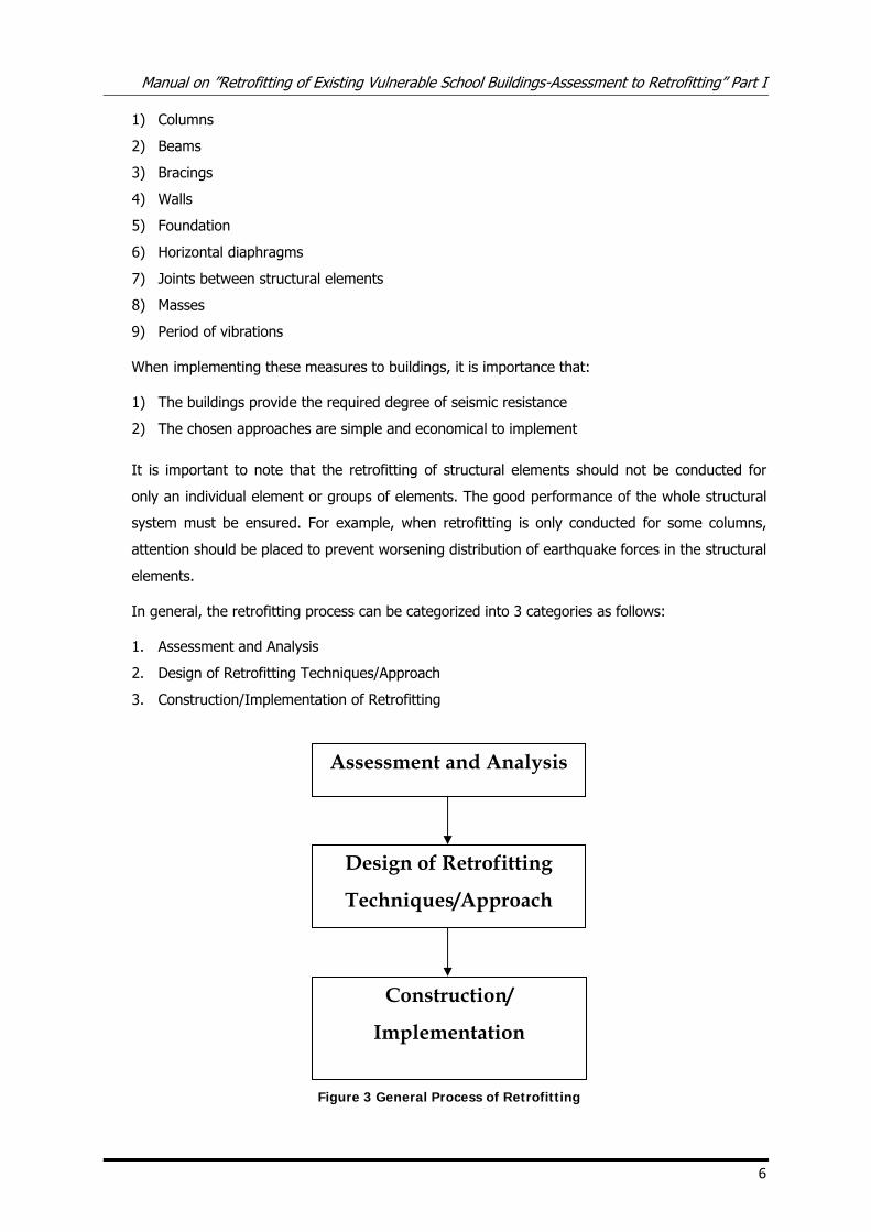
In general, the retrofitting process can be categorized into 3 categories as follows:
1. Assessment and Analysis
2. Design of Retrofitting Techniques/Approach
3. Construction/Implementation of Retrofitting
Figure 3 General Process of Retrofitting
Assessment and Analysis
Design of Retrofitting
Techniques/Approach
Construction/
Implementation
Manual on ”Retrofitting of Existing Vulnerable School Buildings-Assessment to Retrofitting” Part I
7
3. Vulnerability Assessment
Seismic retrofitting becomes an important issue because it includes protecting life and property in
future earthquake as well as protecting investments, lengthening building’s usable life, reducing
demands on post earthquake rescue resources, protecting historic structures, shortening business
interruption, and reducing relocation needs/demands. Based on the large scope of the impacts of
seismic retrofitting, all parameters regarding the impacts should be considered in the decision-
making.
Vulnerability assessment plays an important role in decision-making measures. The purpose of
carrying out a vulnerability assessment analysis of an existing building is to determine the level of risk
associated with loss of serviceability and severe damage or collapse. With the risk quantified, rational
decisions can be made as to whether the buildings should be retrofitted or replaced.
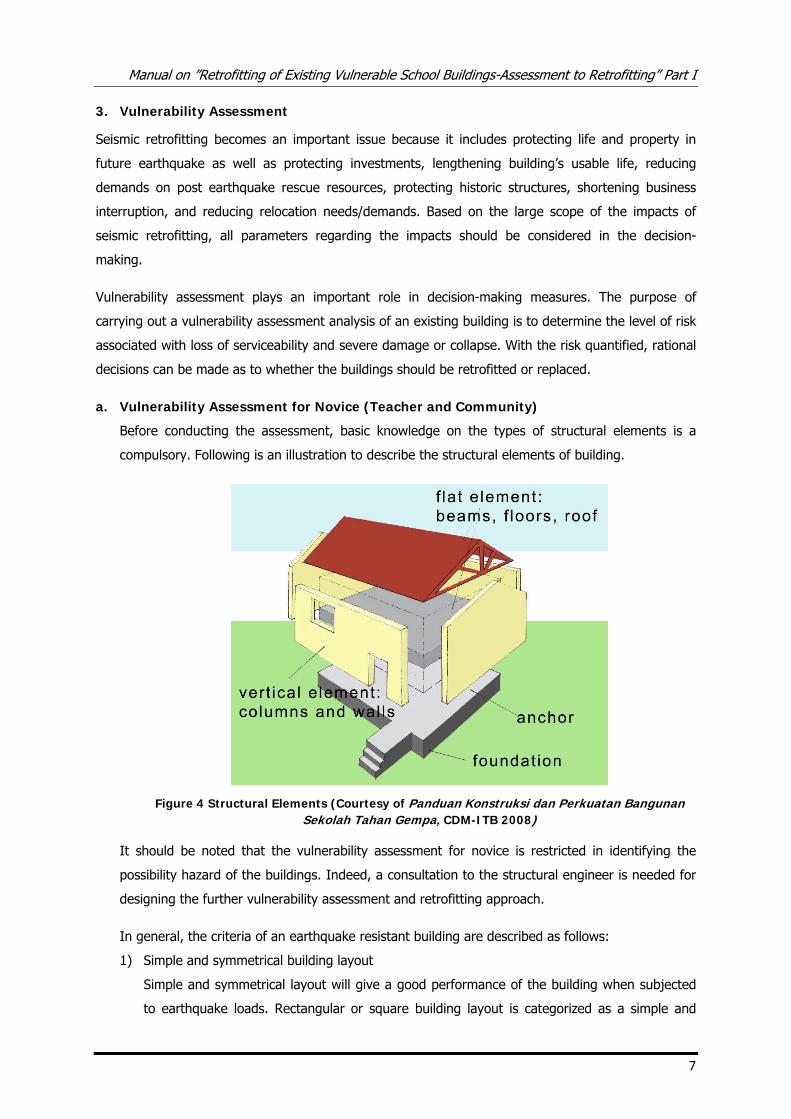
a. Vulnerability Assessment for Novice (Teacher and Community)
Before conducting the assessment, basic knowledge on the types of structural elements is a
compulsory. Following is an illustration to describe the structural elements of building.
Figure 4 Structural Elements (Courtesy of Panduan Konstruksi dan Perkuatan Bangunan Sekolah Tahan Gempa, CDM-ITB 2008)
It should be noted that the vulnerability assessment for novice is restricted in identifying the
possibility hazard of the buildings. Indeed, a consultation to the structural engineer is needed for
designing the further vulnerability assessment and retrofitting approach.
In general, the criteria of an earthquake resistant building are described as follows:
1) Simple and symmetrical building layout
Simple and symmetrical layout will give a good performance of the building when subjected
to earthquake loads. Rectangular or square building layout is categorized as a simple and
Manual on ”Retrofitting of Existing Vulnerable School Buildings-Assessment to Retrofitting” Part I
8
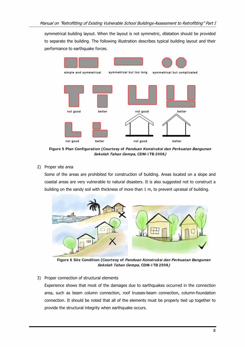
symmetrical building layout. When the layout is not symmetric, dilatation should be provided
to separate the building. The following illustration describes typical building layout and their
performance to earthquake forces.
Figure 5 Plan Configuration (Courtesy of Panduan Konstruksi dan Perkuatan Bangunan
Sekolah Tahan Gempa, CDM-ITB 2008)
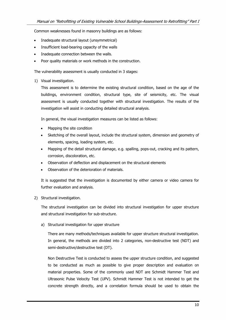
2) Proper site area
Some of the areas are prohibited for construction of building. Areas located on a slope and
coastal areas are very vulnerable to natural disasters. It is also suggested not to construct a
building on the sandy soil with thickness of more than 1 m, to prevent upraisal of building.
Figure 6 Site Condition (Courtesy of Panduan Konstruksi dan Perkuatan Bangunan
Sekolah Tahan Gempa, CDM-ITB 2008)
3) Proper connection of structural elements
Experience shows that most of the damages due to earthquakes occurred in the connection
area, such as beam column connection, roof trusses-beam connection, column-foundation
connection. It should be noted that all of the elements must be properly tied up together to
provide the structural integrity when earthquake occurs.
Manual on ”Retrofitting of Existing Vulnerable School Buildings-Assessment to Retrofitting” Part I
10
Common weaknesses found in masonry buildings are as follows:
• Inadequate structural layout (unsymmetrical)
• Insufficient load-bearing capacity of the walls
• Inadequate connection between the walls.
• Poor quality materials or work methods in the construction.
The vulnerability assessment is usually conducted in 3 stages:
1) Visual investigation.
This assessment is to determine the existing structural condition, based on the age of the
buildings, environment condition, structural type, site of seismicity, etc. The visual
assessment is usually conducted together with structural investigation. The results of the
investigation will assist in conducting detailed structural analysis.
In general, the visual investigation measures can be listed as follows:
• Mapping the site condition
• Sketching of the overall layout, include the structural system, dimension and geometry of
elements, spacing, loading system, etc.
• Mapping of the detail structural damage, e.g. spalling, pops-out, cracking and its pattern,
corrosion, discoloration, etc.
• Observation of deflection and displacement on the structural elements
• Observation of the deterioration of materials.
It is suggested that the investigation is documented by either camera or video camera for
further evaluation and analysis.
2) Structural investigation.
The structural investigation can be divided into structural investigation for upper structure
and structural investigation for sub-structure.
a) Structural investigation for upper structure
There are many methods/techniques available for upper structure structural investigation.
In general, the methods are divided into 2 categories, non-destructive test (NDT) and
semi-destructive/destructive test (DT).
Non Destructive Test is conducted to assess the upper structure condition, and suggested
to be conducted as much as possible to give proper description and evaluation on
material properties. Some of the commonly used NDT are Schmidt Hammer Test and
Ultrasonic Pulse Velocity Test (UPV). Schmidt Hammer Test is not intended to get the
concrete strength directly, and a correlation formula should be used to obtain the
Manual on ”Retrofitting of Existing Vulnerable School Buildings-Assessment to Retrofitting” Part I
11
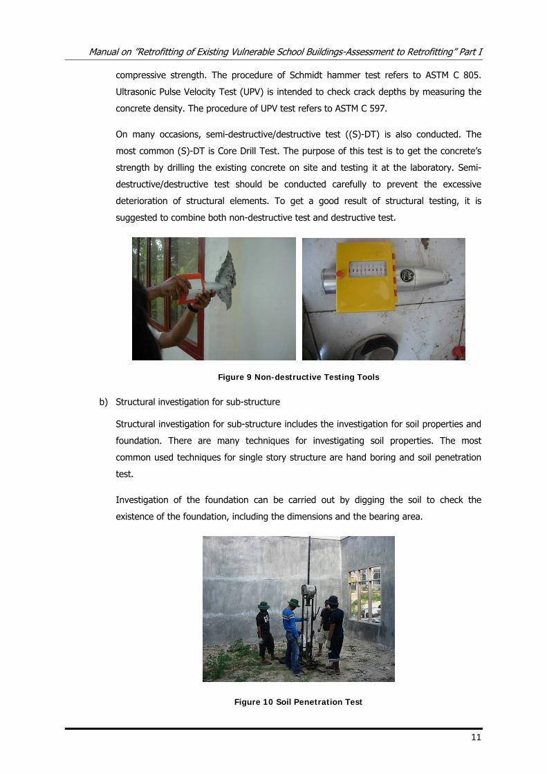
compressive strength. The procedure of Schmidt hammer test refers to ASTM C 805.
Ultrasonic Pulse Velocity Test (UPV) is intended to check crack depths by measuring the
concrete density. The procedure of UPV test refers to ASTM C 597.
On many occasions, semi-destructive/destructive test ((S)-DT) is also conducted. The
most common (S)-DT is Core Drill Test. The purpose of this test is to get the concrete’s
strength by drilling the existing concrete on site and testing it at the laboratory. Semi-
destructive/destructive test should be conducted carefully to prevent the excessive
deterioration of structural elements. To get a good result of structural testing, it is
suggested to combine both non-destructive test and destructive test.
Figure 9 Non-destructive Testing Tools
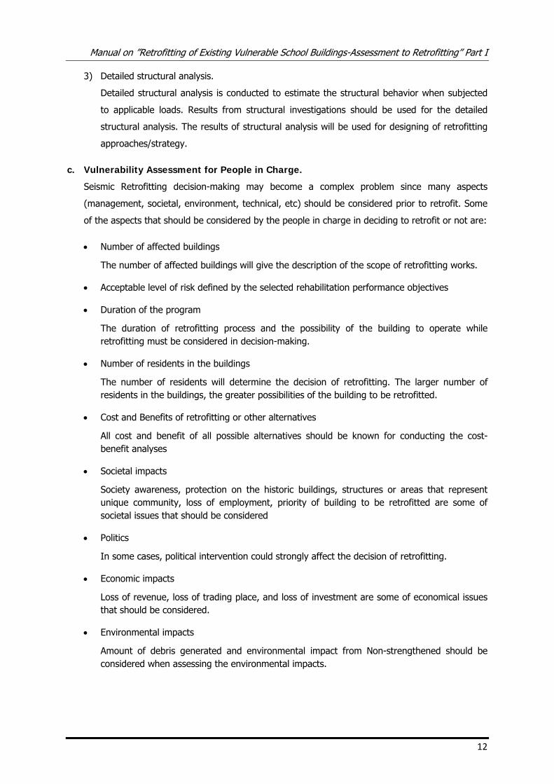
b) Structural investigation for sub-structure
Structural investigation for sub-structure includes the investigation for soil properties and
foundation. There are many techniques for investigating soil properties. The most
common used techniques for single story structure are hand boring and soil penetration
test.
Investigation of the foundation can be carried out by digging the soil to check the
existence of the foundation, including the dimensions and the bearing area.
Figure 10 Soil Penetration Test
Manual on ”Retrofitting of Existing Vulnerable School Buildings-Assessment to Retrofitting” Part I
12
3) Detailed structural analysis.
Detailed structural analysis is conducted to estimate the structural behavior when subjected
to applicable loads. Results from structural investigations should be used for the detailed
structural analysis. The results of structural analysis will be used for designing of retrofitting
approaches/strategy.
c. Vulnerability Assessment for People in Charge.
Seismic Retrofitting decision-making may become a complex problem since many aspects
(management, societal, environment, technical, etc) should be considered prior to retrofit. Some
of the aspects that should be considered by the people in charge in deciding to retrofit or not are:
• Number of affected buildings
The number of affected buildings will give the description of the scope of retrofitting works.
• Acceptable level of risk defined by the selected rehabilitation performance objectives
• Duration of the program
The duration of retrofitting process and the possibility of the building to operate while retrofitting must be considered in decision-making.
• Number of residents in the buildings
The number of residents will determine the decision of retrofitting. The larger number of residents in the buildings, the greater possibilities of the building to be retrofitted.
• Cost and Benefits of retrofitting or other alternatives
All cost and benefit of all possible alternatives should be known for conducting the cost-benefit analyses
• Societal impacts
Society awareness, protection on the historic buildings, structures or areas that represent unique community, loss of employment, priority of building to be retrofitted are some of societal issues that should be considered
• Politics
In some cases, political intervention could strongly affect the decision of retrofitting.
• Economic impacts
Loss of revenue, loss of trading place, and loss of investment are some of economical issues that should be considered.
• Environmental impacts
Amount of debris generated and environmental impact from Non-strengthened should be considered when assessing the environmental impacts.
Manual on ”Retrofitting of Existing Vulnerable School Buildings-Assessment to Retrofitting” Part I
14
4. Retrofitting of School Building.
a. Introduction
As explained in the previous chapter, retrofitting can be a favorable approach because of its
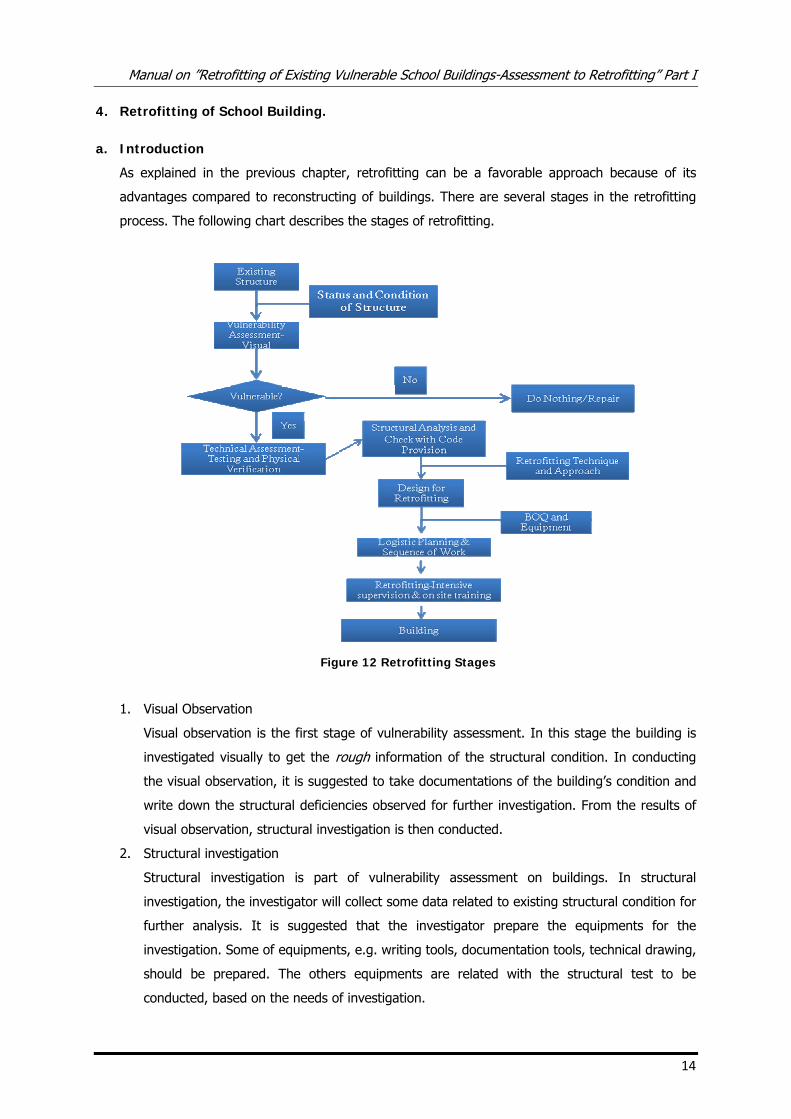
advantages compared to reconstructing of buildings. There are several stages in the retrofitting
process. The following chart describes the stages of retrofitting.
Figure 12 Retrofitting Stages
1. Visual Observation
Visual observation is the first stage of vulnerability assessment. In this stage the building is
investigated visually to get the rough information of the structural condition. In conducting
the visual observation, it is suggested to take documentations of the building’s condition and
write down the structural deficiencies observed for further investigation. From the results of
visual observation, structural investigation is then conducted.
2. Structural investigation
Structural investigation is part of vulnerability assessment on buildings. In structural
investigation, the investigator will collect some data related to existing structural condition for
further analysis. It is suggested that the investigator prepare the equipments for the
investigation. Some of equipments, e.g. writing tools, documentation tools, technical drawing,
should be prepared. The others equipments are related with the structural test to be
conducted, based on the needs of investigation.
Manual on ”Retrofitting of Existing Vulnerable School Buildings-Assessment to Retrofitting” Part I
15
3. Structural analysis
Structural analysis is carried out after completing the investigation. In structural analysis, the
existing building is analyzed and subjected to earthquake forces based on current building
codes. The results of the structural investigation should be used for determining the existing
buildings’ properties. The structural condition is evaluated whether it is vulnerable or not. If
the building is vulnerable, then design of the retrofitting approach should be conducted.
4. Design of retrofitting approach
The retrofitting approach adopted should consider the followings criteria:
a) The degree of seismic resistance required for the buildings.
The buildings must be designed to provide enough strength and ductility when subjected
to earthquake forces. It should also be noted that the buildings must be designed for a
certain acceptable damage level. For school buildings, the buildings must not have
structural damage due to earthquake.
b) The chosen approach is simple and economical to implement
In designing the retrofitting approach, the techniques should be compatible to the skill of
the workers. The techniques should be simple and economical to implement.
5. Construction/ implementation
The construction of the buildings should consider duration of construction. The construction
process must be supervised intensively to ensure the quality of works.
b. Various Techniques on Retrofitting
There are various techniques on retrofitting. The retrofitting strategy can be conducted by
strengthening the overstressed members, reducing the force distribution, reducing the seismic
demands, etc.
In implementing the retrofitting approach, the techniques adopted must be appropriate with the
structural deficiencies. For example, if the structural assessment shows lack of stiffness of the
structure, the possible retrofitting techniques could be to increase the structural elements
dimensions or to insert more structural elements, etc.
In this chapter, some common retrofitting techniques will be presented. However, it should be
noted that the decision of which techniques to be implemented must be decided by an engineer.
1) Inserting structural elements
A need of inserting of structural elements is due to intentions of reducing force distributed in
each element (by reducing the span of structural elements). Moreover, inserting new
structural elements will increase the structural stiffness of overall structure. In inserting the
new structural elements, the following criteria should be taken into consideration:
• A good detailing must be provided in the connection areas, e.g. in beam-column joint,
beam-foundation connection, column-foundation connection.
Manual on ”Retrofitting of Existing Vulnerable School Buildings-Assessment to Retrofitting” Part I
16
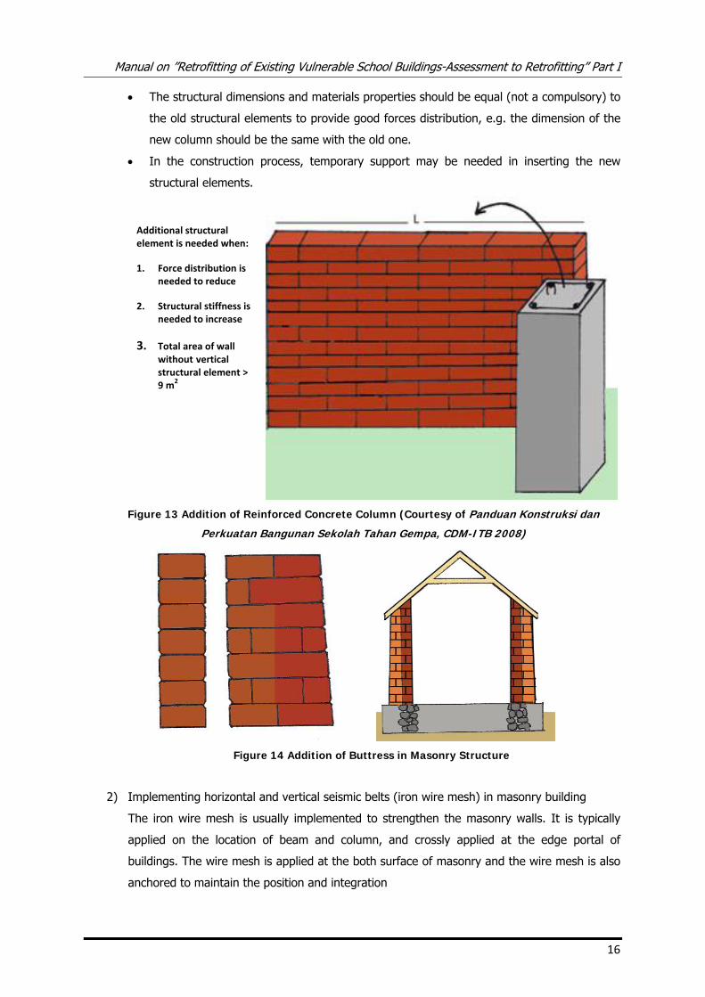
• The structural dimensions and materials properties should be equal (not a compulsory) to
the old structural elements to provide good forces distribution, e.g. the dimension of the
new column should be the same with the old one.
• In the construction process, temporary support may be needed in inserting the new
structural elements.
Figure 13 Addition of Reinforced Concrete Column (Courtesy of Panduan Konstruksi dan
Perkuatan Bangunan Sekolah Tahan Gempa, CDM-ITB 2008)
Figure 14 Addition of Buttress in Masonry Structure
2) Implementing horizontal and vertical seismic belts (iron wire mesh) in masonry building
The iron wire mesh is usually implemented to strengthen the masonry walls. It is typically
applied on the location of beam and column, and crossly applied at the edge portal of
buildings. The wire mesh is applied at the both surface of masonry and the wire mesh is also
anchored to maintain the position and integration
Additional structural element is needed when:
1. Force distribution is needed to reduce
2. Structural stiffness is needed to increase
3. Total area of wall without vertical structural element > 9 m2
Manual on ”Retrofitting of Existing Vulnerable School Buildings-Assessment to Retrofitting” Part I
17
kaw
300
atan beton
LANTAI
300
uatan beton
LANTAI
400400
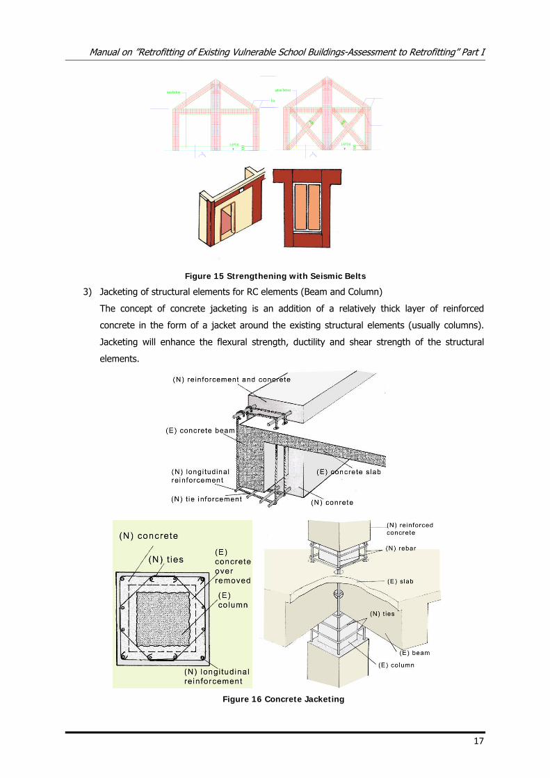
Figure 15 Strengthening with Seismic Belts
3) Jacketing of structural elements for RC elements (Beam and Column)
The concept of concrete jacketing is an addition of a relatively thick layer of reinforced
concrete in the form of a jacket around the existing structural elements (usually columns).
Jacketing will enhance the flexural strength, ductility and shear strength of the structural
elements.
Figure 16 Concrete Jacketing
Manual on ”Retrofitting of Existing Vulnerable School Buildings-Assessment to Retrofitting” Part I
18
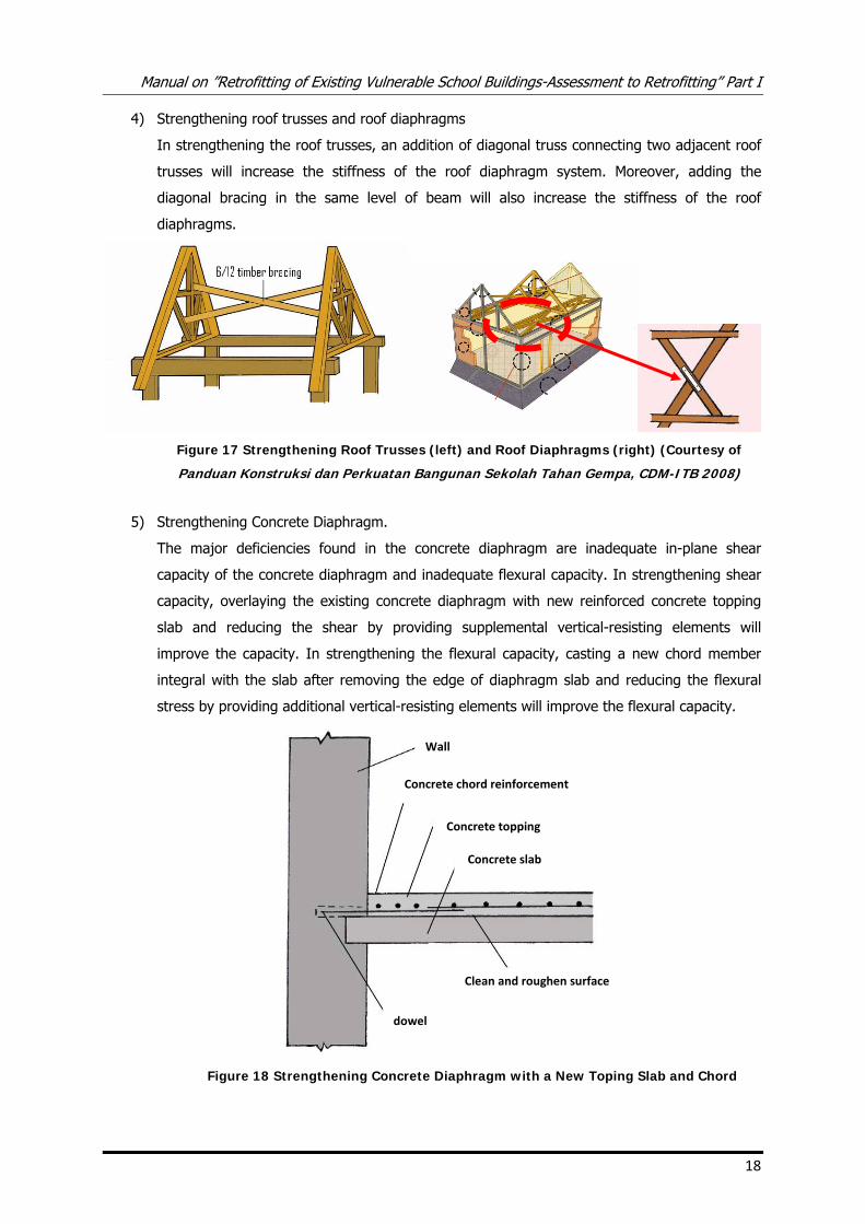
4) Strengthening roof trusses and roof diaphragms
In strengthening the roof trusses, an addition of diagonal truss connecting two adjacent roof
trusses will increase the stiffness of the roof diaphragm system. Moreover, adding the
diagonal bracing in the same level of beam will also increase the stiffness of the roof
diaphragms.
Figure 17 Strengthening Roof Trusses (left) and Roof Diaphragms (right) (Courtesy of
Panduan Konstruksi dan Perkuatan Bangunan Sekolah Tahan Gempa, CDM-ITB 2008)
5) Strengthening Concrete Diaphragm.
The major deficiencies found in the concrete diaphragm are inadequate in-plane shear
capacity of the concrete diaphragm and inadequate flexural capacity. In strengthening shear
capacity, overlaying the existing concrete diaphragm with new reinforced concrete topping
slab and reducing the shear by providing supplemental vertical-resisting elements will
improve the capacity. In strengthening the flexural capacity, casting a new chord member
integral with the slab after removing the edge of diaphragm slab and reducing the flexural
stress by providing additional vertical-resisting elements will improve the flexural capacity.
Figure 18 Strengthening Concrete Diaphragm with a New Toping Slab and Chord
Wall
Concrete chord reinforcement
Concrete topping
Concrete slab
Clean and roughen surface
dowel
Manual on ”Retrofitting of Existing Vulnerable School Buildings-Assessment to Retrofitting” Part I
19
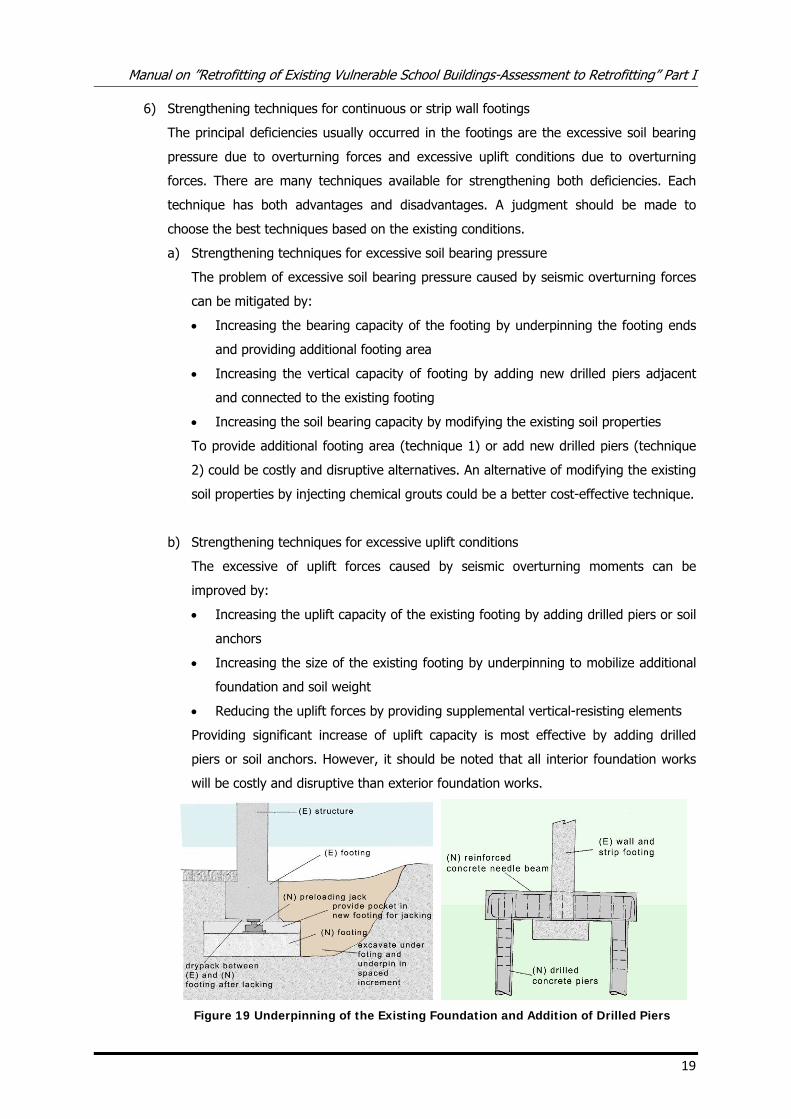
6) Strengthening techniques for continuous or strip wall footings
The principal deficiencies usually occurred in the footings are the excessive soil bearing
pressure due to overturning forces and excessive uplift conditions due to overturning
forces. There are many techniques available for strengthening both deficiencies. Each
technique has both advantages and disadvantages. A judgment should be made to
choose the best techniques based on the existing conditions.
a) Strengthening techniques for excessive soil bearing pressure
The problem of excessive soil bearing pressure caused by seismic overturning forces
can be mitigated by:
• Increasing the bearing capacity of the footing by underpinning the footing ends
and providing additional footing area
• Increasing the vertical capacity of footing by adding new drilled piers adjacent
and connected to the existing footing
• Increasing the soil bearing capacity by modifying the existing soil properties
To provide additional footing area (technique 1) or add new drilled piers (technique
2) could be costly and disruptive alternatives. An alternative of modifying the existing
soil properties by injecting chemical grouts could be a better cost-effective technique.
b) Strengthening techniques for excessive uplift conditions
The excessive of uplift forces caused by seismic overturning moments can be
improved by:
• Increasing the uplift capacity of the existing footing by adding drilled piers or soil
anchors
• Increasing the size of the existing footing by underpinning to mobilize additional
foundation and soil weight
• Reducing the uplift forces by providing supplemental vertical-resisting elements
Providing significant increase of uplift capacity is most effective by adding drilled
piers or soil anchors. However, it should be noted that all interior foundation works
will be costly and disruptive than exterior foundation works.
Figure 19 Underpinning of the Existing Foundation and Addition of Drilled Piers
Manual on ”Retrofitting of Existing Vulnerable School Buildings-Assessment to Retrofitting” Part I
20
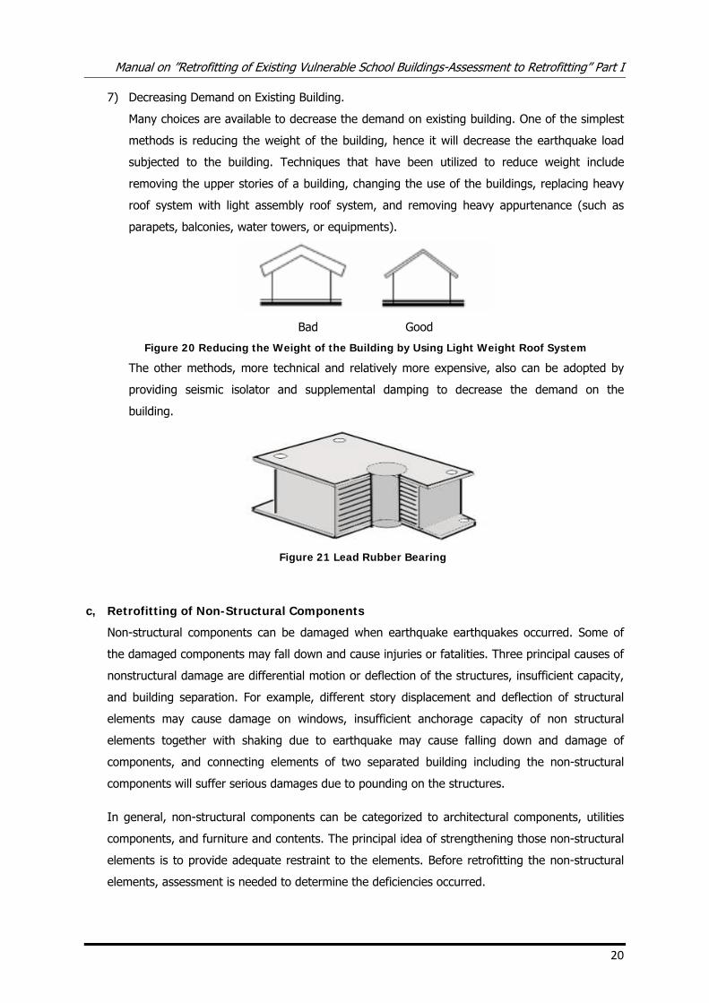
7) Decreasing Demand on Existing Building.
Many choices are available to decrease the demand on existing building. One of the simplest
methods is reducing the weight of the building, hence it will decrease the earthquake load
subjected to the building. Techniques that have been utilized to reduce weight include
removing the upper stories of a building, changing the use of the buildings, replacing heavy
roof system with light assembly roof system, and removing heavy appurtenance (such as
parapets, balconies, water towers, or equipments).
Bad Good
Figure 20 Reducing the Weight of the Building by Using Light Weight Roof System
The other methods, more technical and relatively more expensive, also can be adopted by
providing seismic isolator and supplemental damping to decrease the demand on the
building.
Figure 21 Lead Rubber Bearing
c, Retrofitting of Non-Structural Components
Non-structural components can be damaged when earthquake earthquakes occurred. Some of
the damaged components may fall down and cause injuries or fatalities. Three principal causes of
nonstructural damage are differential motion or deflection of the structures, insufficient capacity,
and building separation. For example, different story displacement and deflection of structural
elements may cause damage on windows, insufficient anchorage capacity of non structural
elements together with shaking due to earthquake may cause falling down and damage of
components, and connecting elements of two separated building including the non-structural
components will suffer serious damages due to pounding on the structures.
In general, non-structural components can be categorized to architectural components, utilities
components, and furniture and contents. The principal idea of strengthening those non-structural
elements is to provide adequate restraint to the elements. Before retrofitting the non-structural
elements, assessment is needed to determine the deficiencies occurred.
Manual on ”Retrofitting of Existing Vulnerable School Buildings-Assessment to Retrofitting” Part I
21
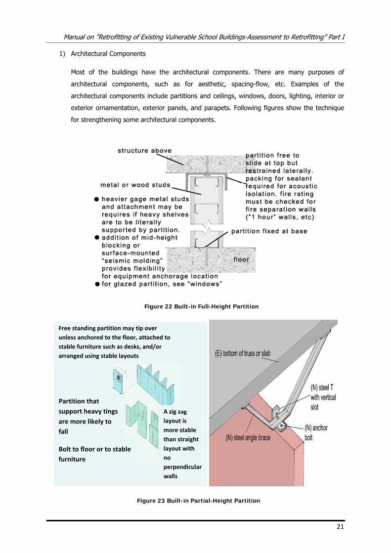
1) Architectural Components
Most of the buildings have the architectural components. There are many purposes of
architectural components, such as for aesthetic, spacing-flow, etc. Examples of the
architectural components include partitions and ceilings, windows, doors, lighting, interior or
exterior ornamentation, exterior panels, and parapets. Following figures show the technique
for strengthening some architectural components.
Figure 22 Built-in Full-Height Partition
Figure 23 Built-in Partial-Height Partition
Free standing partition may tip over unless anchored to the floor, attached to stable furniture such as desks, and/or arranged using stable layouts
A zig zag layout is more stable than straight layout with no perpendicular walls
Bolt to floor or to stable furniture
Partition that support heavy tings are more likely to fall
Manual on ”Retrofitting of Existing Vulnerable School Buildings-Assessment to Retrofitting” Part I
22
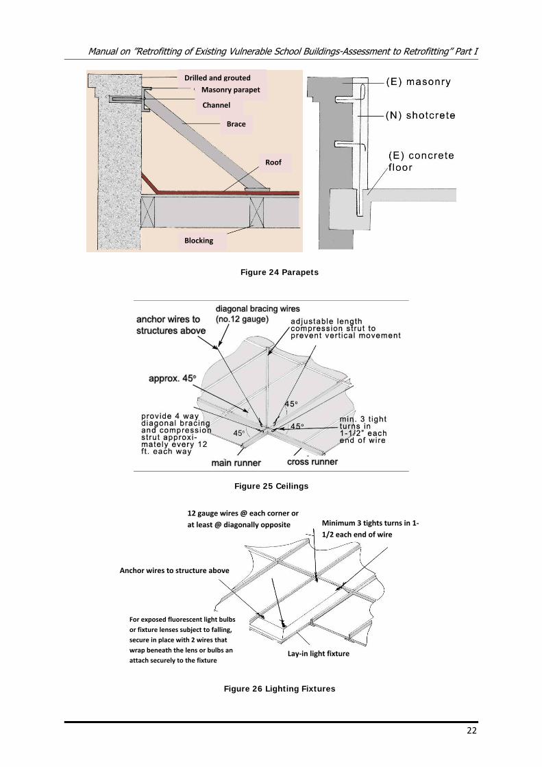
Figure 24 Parapets
Figure 25 Ceilings
Figure 26 Lighting Fixtures
Drilled and grouted
Masonry parapet
Channel
Brace
Roof
Blocking
12 gauge wires @ each corner or at least @ diagonally opposite Minimum 3 tights turns in 1‐
1/2 each end of wire
Anchor wires to structure above
Lay‐in light fixture
For exposed fluorescent light bulbs or fixture lenses subject to falling, secure in place with 2 wires that wrap beneath the lens or bulbs and attach securely to the fixture
Manual on ”Retrofitting of Existing Vulnerable School Buildings-Assessment to Retrofitting” Part I
23
To prevent damage to stairs, they should be modified to allow them to slide at landings with
proper details. This is desirable for flexible frame buildings. Next, to prevent damage to
windows, it is suggested to use tempered glass. Tempered glass will reduce the seismic
hazard. It may still break, but in a small dull fragments. Polyester shatter resistant films will
help holding together fragments of any panels that crack in earthquake.
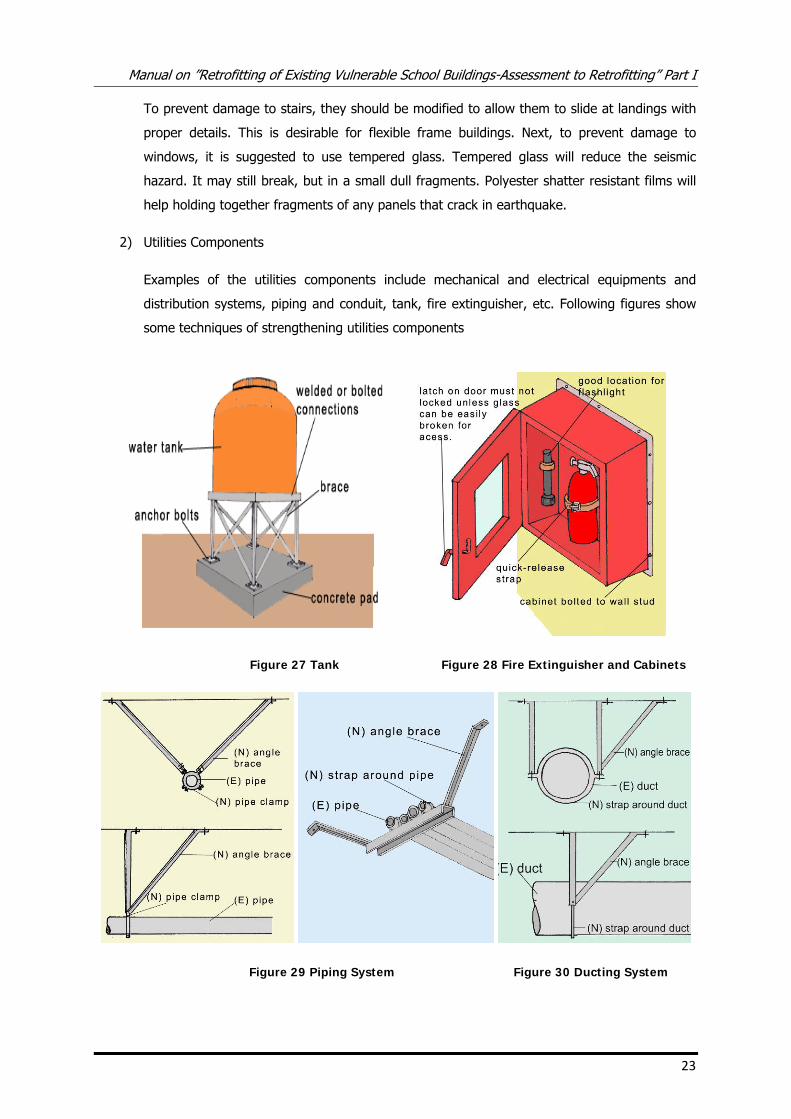
2) Utilities Components
Examples of the utilities components include mechanical and electrical equipments and
distribution systems, piping and conduit, tank, fire extinguisher, etc. Following figures show
some techniques of strengthening utilities components
Figure 27 Tank Figure 28 Fire Extinguisher and Cabinets
Figure 29 Piping System Figure 30 Ducting System
Manual on ”Retrofitting of Existing Vulnerable School Buildings-Assessment to Retrofitting” Part I
24
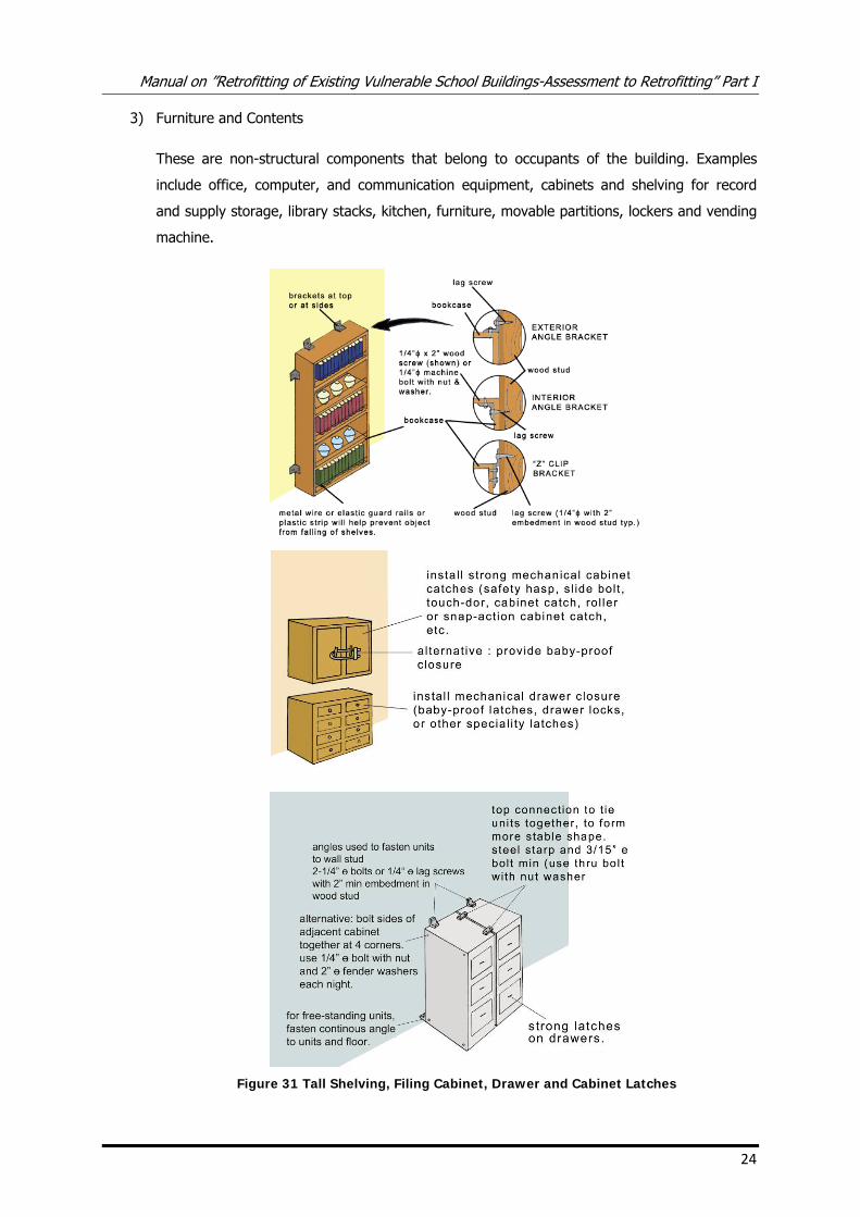
3) Furniture and Contents
These are non-structural components that belong to occupants of the building. Examples
include office, computer, and communication equipment, cabinets and shelving for record
and supply storage, library stacks, kitchen, furniture, movable partitions, lockers and vending
machine.
Figure 31 Tall Shelving, Filing Cabinet, Drawer and Cabinet Latches
Manual on ”Retrofitting of Existing Vulnerable School Buildings-Assessment to Retrofitting” Part I
25
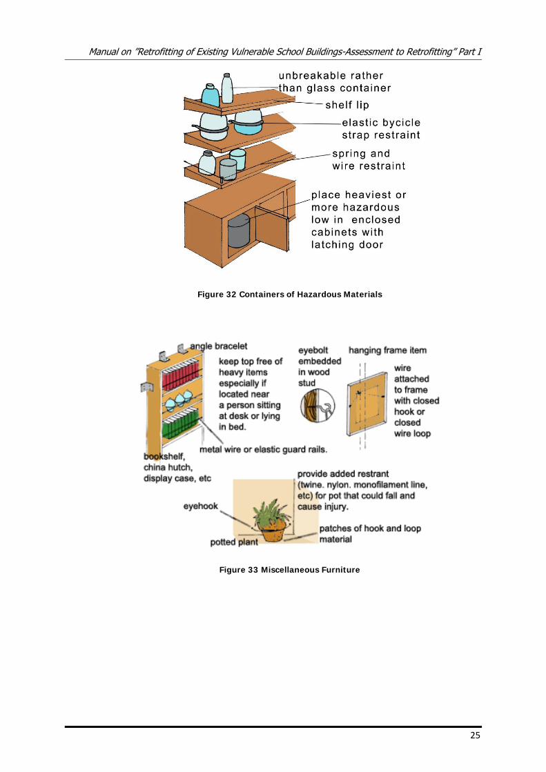
Figure 32 Containers of Hazardous Materials
Figure 33 Miscellaneous Furniture
Manual on ”Retrofitting of Existing Vulnerable School Buildings-Assessment to Retrofitting” Part I
27
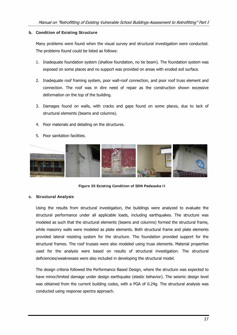
b. Condition of Existing Structure
Many problems were found when the visual survey and structural investigation were conducted.
The problems found could be listed as follows:
1. Inadequate foundation system (shallow foundation, no tie beam). The foundation system was
exposed on some places and no support was provided on areas with eroded soil surface.
2. Inadequate roof framing system, poor wall-roof connection, and poor roof truss element and
connection. The roof was in dire need of repair as the construction shown excessive
deformation on the top of the building.
3. Damages found on walls, with cracks and gaps found on some places, due to lack of
structural elements (beams and columns).
4. Poor materials and detailing on the structures.
5. Poor sanitation facilities.
Figure 35 Existing Condition of SDN Padasuka II
c. Structural Analysis
Using the results from structural investigation, the buildings were analyzed to evaluate the
structural performance under all applicable loads, including earthquakes. The structure was
modeled as such that the structural elements (beams and columns) formed the structural frame,
while masonry walls were modeled as plate elements. Both structural frame and plate elements
provided lateral resisting system for the structure. The foundation provided support for the
structural frames. The roof trusses were also modeled using truss elements. Material properties
used for the analysis were based on results of structural investigation. The structural
deficiencies/weaknesses were also included in developing the structural model.
The design criteria followed the Performance Based Design, where the structure was expected to
have minor/limited damage under design earthquake (elastic behavior). The seismic design level
was obtained from the current building codes, with a PGA of 0.24g. The structural analysis was
conducted using response spectra approach.
Manual on ”Retrofitting of Existing Vulnerable School Buildings-Assessment to Retrofitting” Part I
28
Results from structural analysis show that the structure did not have adequate capacity in
resisting lateral loads. Checking of connection capacity also revealed unsatisfactory results.
Moreover, the trusses required improvement to be able to support all applicable loads.
Combined with data obtained from visual and structural investigations, results from structural
analysis were then used to design appropriate retrofitting approach.
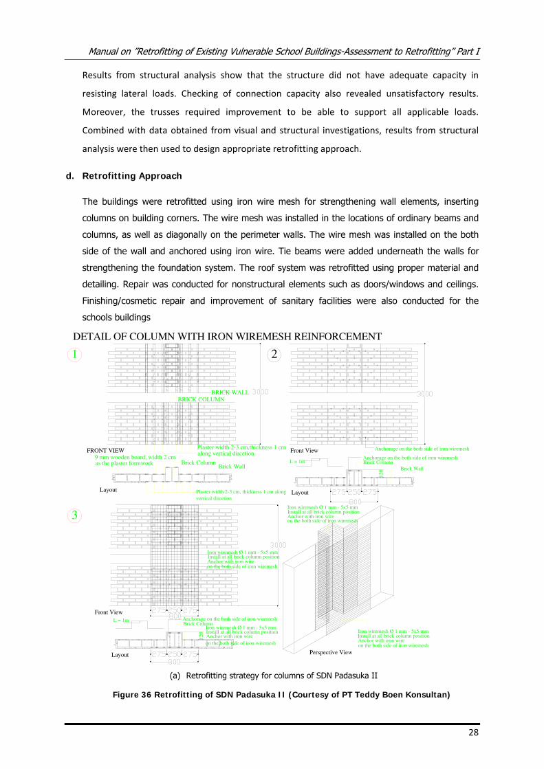
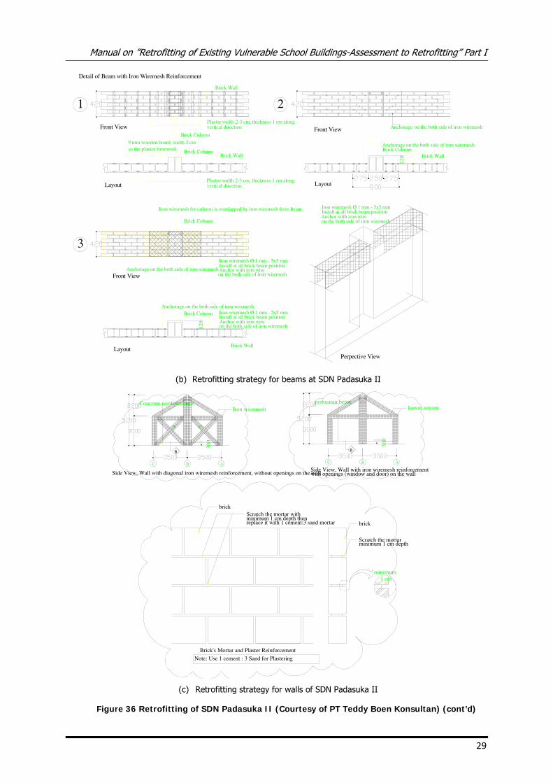
d. Retrofitting Approach
The buildings were retrofitted using iron wire mesh for strengthening wall elements, inserting
columns on building corners. The wire mesh was installed in the locations of ordinary beams and
columns, as well as diagonally on the perimeter walls. The wire mesh was installed on the both
side of the wall and anchored using iron wire. Tie beams were added underneath the walls for
strengthening the foundation system. The roof system was retrofitted using proper material and
detailing. Repair was conducted for nonstructural elements such as doors/windows and ceilings.
Finishing/cosmetic repair and improvement of sanitary facilities were also conducted for the
schools buildings
Brick Wall
Plaster width 2−3 cm,thickness 1 cmalong vertical dircetion
Brick Column
BRICK WALLBRICK COLUMN
Brick WallBrick Column
9 mm wooden board, width 2 cmas the plaster formwork
Anchorage on the both side of iron wiremesh
Anchorage on the both side of iron wiremesh
Iron wiremesh Ø 1 mm − 5x5 mmInstall at all brick column positionAnchor with iron wireon the both side of iron wiremesh
DETAIL OF COLUMN WITH IRON WIREMESH REINFORCEMENT
1 2
3
FRONT VIEW
Layout
Front View
Layout
Front View
120
Perspective View
L = 1m
Layout
120
L = 1m
Plaster width 2−3 cm, thickness 1 cm alongvertical dircetion
Anchorage on the both side of iron wiremeshBrick Column
Iron wiremesh Ø 1 mm − 5x5 mmInstall at all brick column positionAnchor with iron wireon the both side of iron wiremesh
Iron wiremesh Ø 1 mm − 5x5 mmInstall at all brick column positionAnchor with iron wireon the both side of iron wiremesh
Iron wiremesh Ø 1 mm − 5x5 mmInstall at all brick column positionAnchor with iron wireon the both side of iron wiremesh
(a) Retrofitting strategy for columns of SDN Padasuka II
Figure 36 Retrofitting of SDN Padasuka II (Courtesy of PT Teddy Boen Konsultan)
Manual on ”Retrofitting of Existing Vulnerable School Buildings-Assessment to Retrofitting” Part I
29
Brick WallBrick Column
Brick Column
Detail of Beam with Iron Wiremesh Reinforcement
Brick Wall
1 2
3
Front View
Layout
Front View
Front View
Perpective View
Layout
120
Brick Column
Iron wiremesh for column is overlapped by iron wiremesh from beam.
Brick Wall
Brick Column
Layout
120
Plaster width 2−3 cm, thickness 1 cm alongvertical dircetion
Plaster width 2−3 cm, thickness 1 cm alongvertical dircetion
9 mm wooden board, width 2 cmas the plaster formwork
Brick WallBrick Column
Anchorage on the both side of iron wiremesh
Anchorage on the both side of iron wiremesh
Iron wiremesh Ø 1 mm − 5x5 mmInstall at all brick beam positionAnchor with iron wireon the both side of iron wiremesh
Anchorage on the both side of iron wiremesh
Anchorage on the both side of iron wiremeshIron wiremesh Ø 1 mm − 5x5 mmInstall at all brick beam positionAnchor with iron wireon the both side of iron wiremesh
Iron wiremesh Ø 1 mm − 5x5 mmInstall at all brick beam positionAnchor with iron wireon the both side of iron wiremesh
(b) Retrofitting strategy for beams at SDN Padasuka II
Side View, Wall with diagonal iron wiremesh reinforcement, without openings on the wall
Iron wiremesh
ABC
300
Concrete reinforcement
B
Floor
400400
Side View, Wall with iron wiremesh reinforcement
kawat anyam
ABC
300
perkuatan beton
B
LANTAI
with openings (window and door) on the wall
Scratch the mortarminimum 1 cm depth
minimum 1 cm
brick
Scratch the mortar withminimum 1 cm depth thenreplace it with 1 cement:3 sand mortar
brick
Brick’s Mortar and Plaster Reinforcement
Note: Use 1 cement : 3 Sand for Plastering
(c) Retrofitting strategy for walls of SDN Padasuka II
Figure 36 Retrofitting of SDN Padasuka II (Courtesy of PT Teddy Boen Konsultan) (cont’d)
Manual on ”Retrofitting of Existing Vulnerable School Buildings-Assessment to Retrofitting” Part I
31
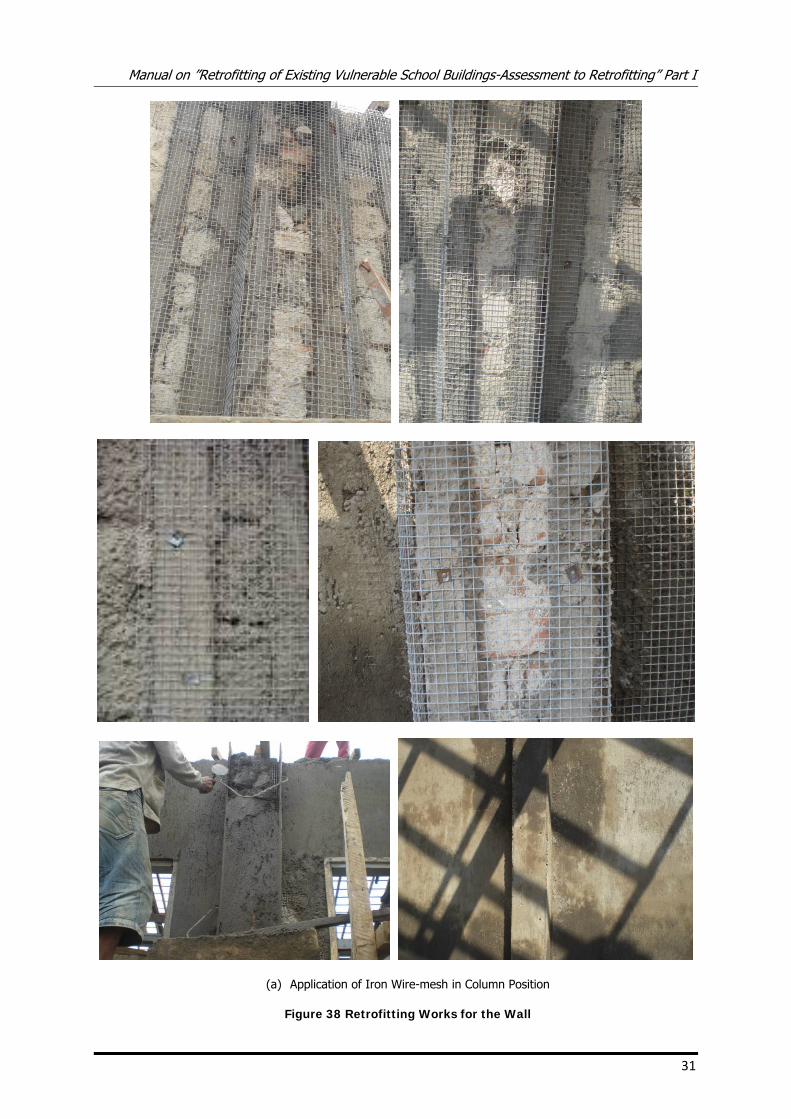
(a) Application of Iron Wire-mesh in Column Position
Figure 38 Retrofitting Works for the Wall
Manual on ”Retrofitting of Existing Vulnerable School Buildings-Assessment to Retrofitting” Part I
35
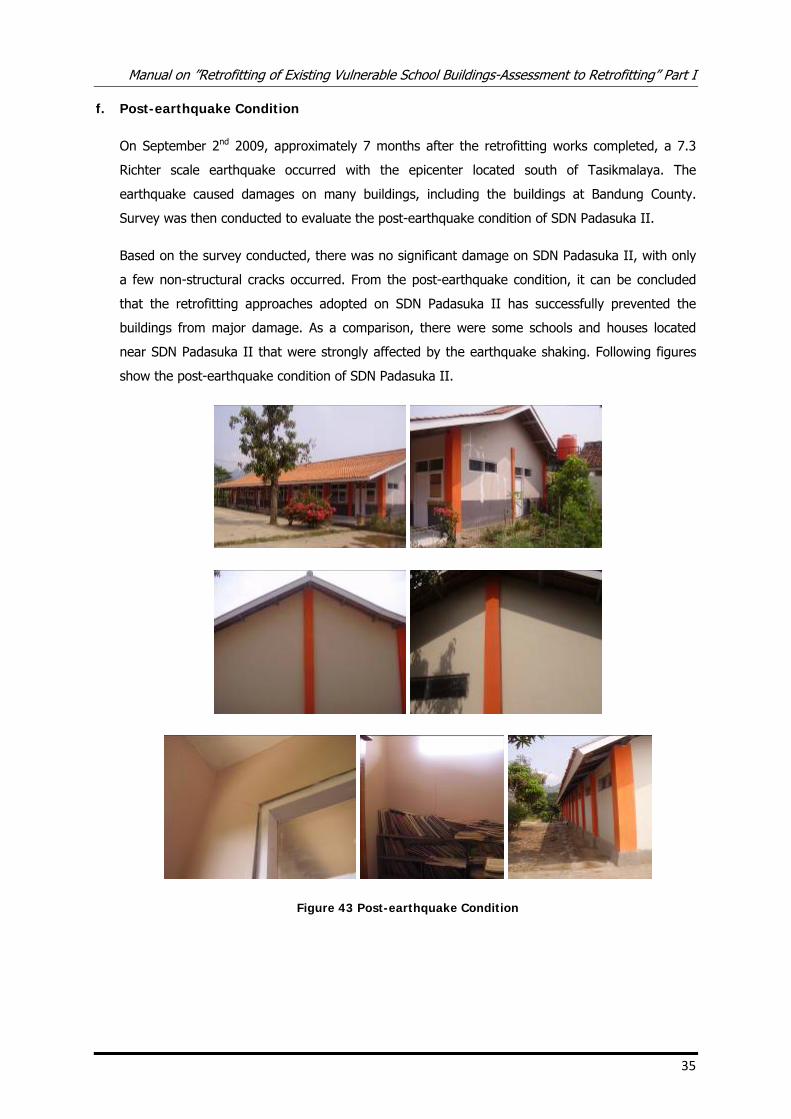
f. Post-earthquake Condition
On September 2nd 2009, approximately 7 months after the retrofitting works completed, a 7.3
Richter scale earthquake occurred with the epicenter located south of Tasikmalaya. The
earthquake caused damages on many buildings, including the buildings at Bandung County.
Survey was then conducted to evaluate the post-earthquake condition of SDN Padasuka II.
Based on the survey conducted, there was no significant damage on SDN Padasuka II, with only
a few non-structural cracks occurred. From the post-earthquake condition, it can be concluded
that the retrofitting approaches adopted on SDN Padasuka II has successfully prevented the
buildings from major damage. As a comparison, there were some schools and houses located
near SDN Padasuka II that were strongly affected by the earthquake shaking. Following figures
show the post-earthquake condition of SDN Padasuka II.
Figure 43 Post-earthquake Condition
Manual on ”Retrofitting of Existing Vulnerable School Buildings-Assessment to Retrofitting” Part I
36
6. Case Studies: Retrofitting of School Building: SDN 13 Syamtalira Arun (Save the
Children project, with design and technical assistance from Syiah Kuala University)
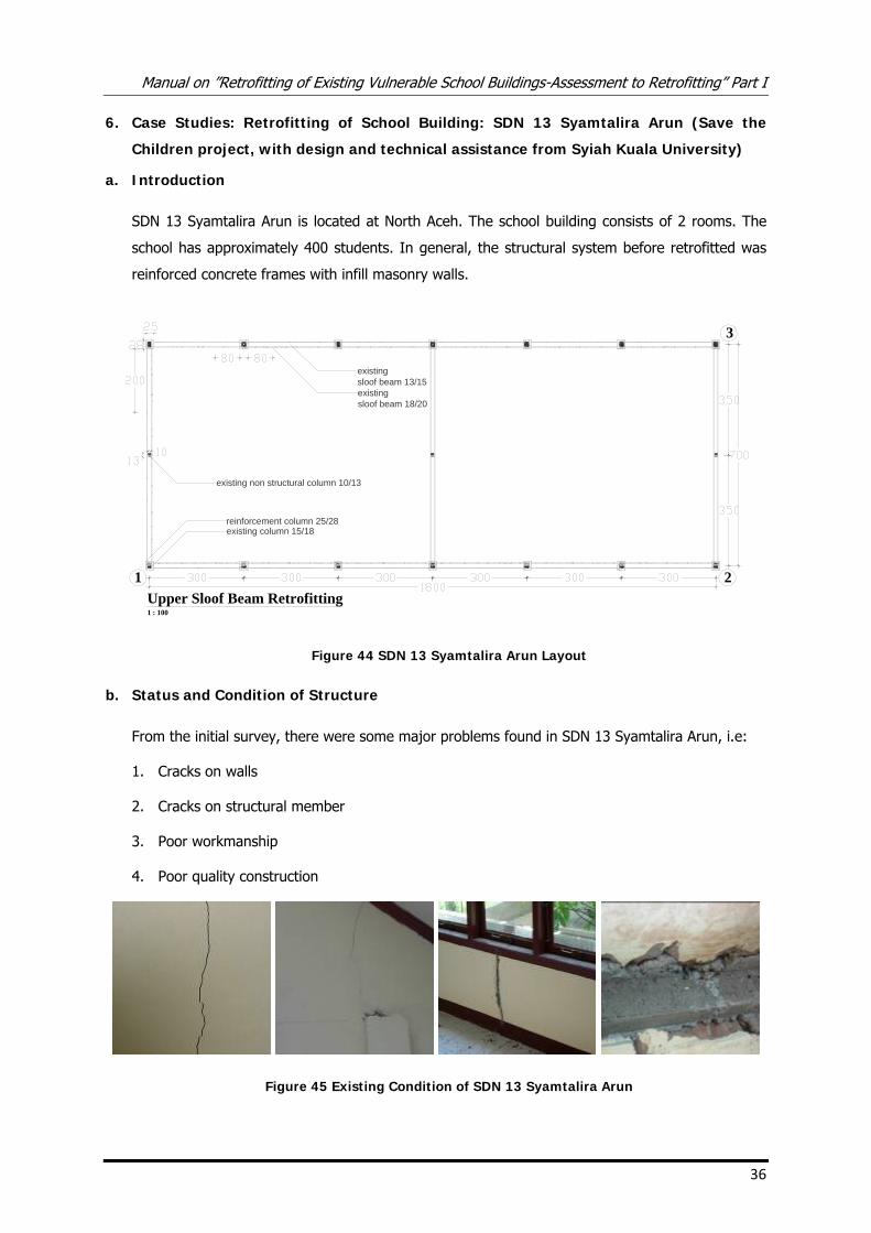
a. Introduction
SDN 13 Syamtalira Arun is located at North Aceh. The school building consists of 2 rooms. The
school has approximately 400 students. In general, the structural system before retrofitted was
reinforced concrete frames with infill masonry walls.
existingsloof beam 13/15
existing non structural column 10/13
Upper Sloof Beam Retrofitting1 : 100
1 2
3
reinforcement column 25/28
existingsloof beam 18/20
existing column 15/18
Figure 44 SDN 13 Syamtalira Arun Layout
b. Status and Condition of Structure
From the initial survey, there were some major problems found in SDN 13 Syamtalira Arun, i.e:
1. Cracks on walls
2. Cracks on structural member
3. Poor workmanship
4. Poor quality construction
Figure 45 Existing Condition of SDN 13 Syamtalira Arun
Manual on ”Retrofitting of Existing Vulnerable School Buildings-Assessment to Retrofitting” Part I
37
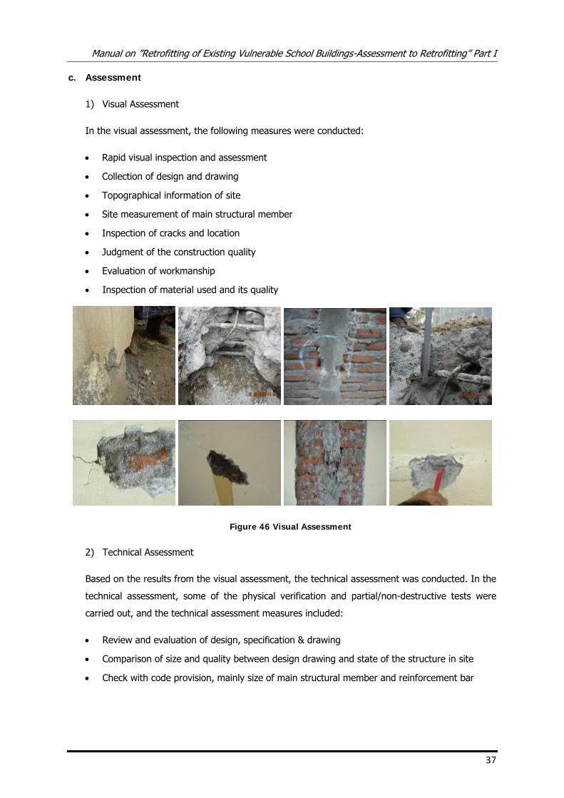
c. Assessment
1) Visual Assessment
In the visual assessment, the following measures were conducted:
• Rapid visual inspection and assessment
• Collection of design and drawing
• Topographical information of site
• Site measurement of main structural member
• Inspection of cracks and location
• Judgment of the construction quality
• Evaluation of workmanship
• Inspection of material used and its quality
Figure 46 Visual Assessment
2) Technical Assessment
Based on the results from the visual assessment, the technical assessment was conducted. In the
technical assessment, some of the physical verification and partial/non-destructive tests were
carried out, and the technical assessment measures included:
• Review and evaluation of design, specification & drawing
• Comparison of size and quality between design drawing and state of the structure in site
• Check with code provision, mainly size of main structural member and reinforcement bar
Manual on ”Retrofitting of Existing Vulnerable School Buildings-Assessment to Retrofitting” Part I
39
based on results of structural investigation. The structural analysis was conducted based on the
following codes:
• PPI 1983 – Loading standard
• SNI -03-2847-2002 – Standard for design of concrete structures
• SNI O3 – 1726 – 2003 – Standard for earthquake resistant building
The structural analysis revealed that the open frame structure did not have adequate capacity in
resisting lateral loads. Combined with data obtained from visual and structural investigations,
results from structural analysis were then used to design appropriate retrofitting approach.
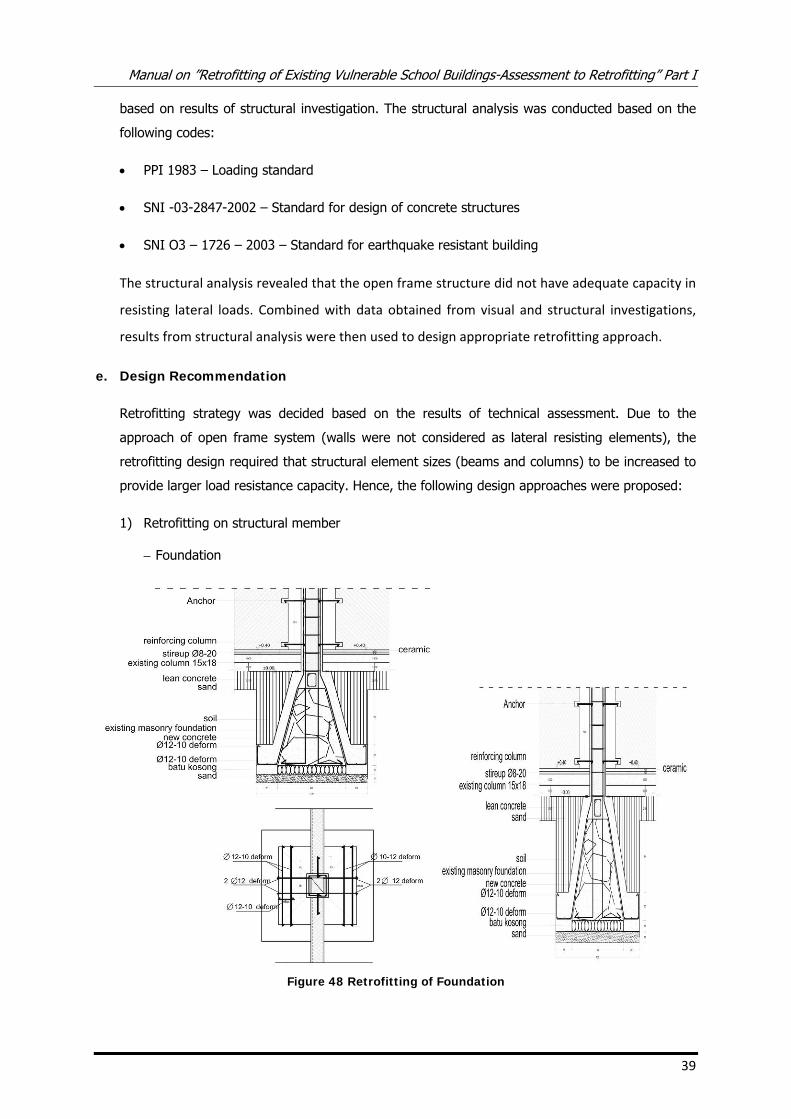
e. Design Recommendation
Retrofitting strategy was decided based on the results of technical assessment. Due to the
approach of open frame system (walls were not considered as lateral resisting elements), the
retrofitting design required that structural element sizes (beams and columns) to be increased to
provide larger load resistance capacity. Hence, the following design approaches were proposed:
1) Retrofitting on structural member
– Foundation
Figure 48 Retrofitting of Foundation
Manual on ”Retrofitting of Existing Vulnerable School Buildings-Assessment to Retrofitting” Part I
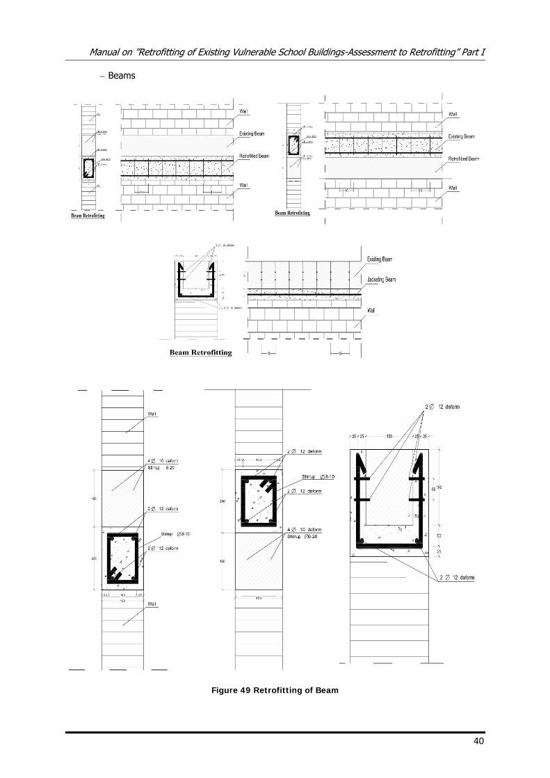
40
– Beams
Figure 49 Retrofitting of Beam
Manual on ”Retrofitting of Existing Vulnerable School Buildings-Assessment to Retrofitting” Part I
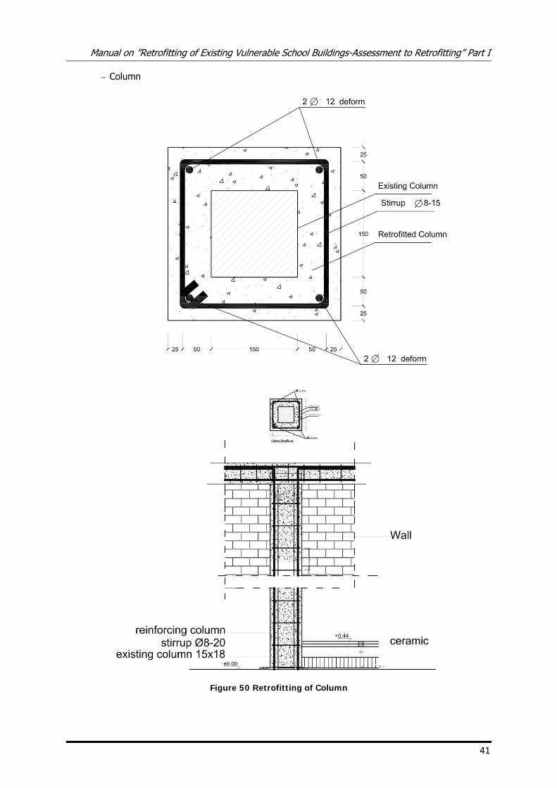
41
– Column
Figure 50 Retrofitting of Column
Manual on ”Retrofitting of Existing Vulnerable School Buildings-Assessment to Retrofitting” Part I
42
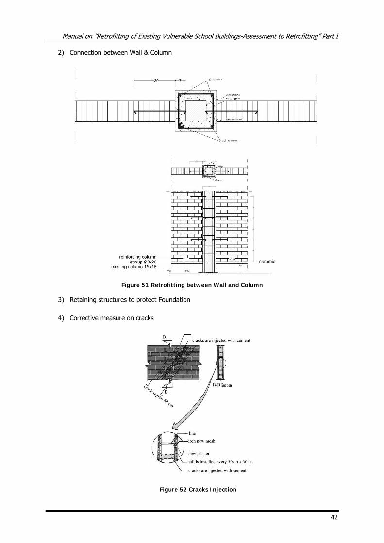
2) Connection between Wall & Column
Figure 51 Retrofitting between Wall and Column
3) Retaining structures to protect Foundation
4) Corrective measure on cracks
Figure 52 Cracks Injection

APPENDIX
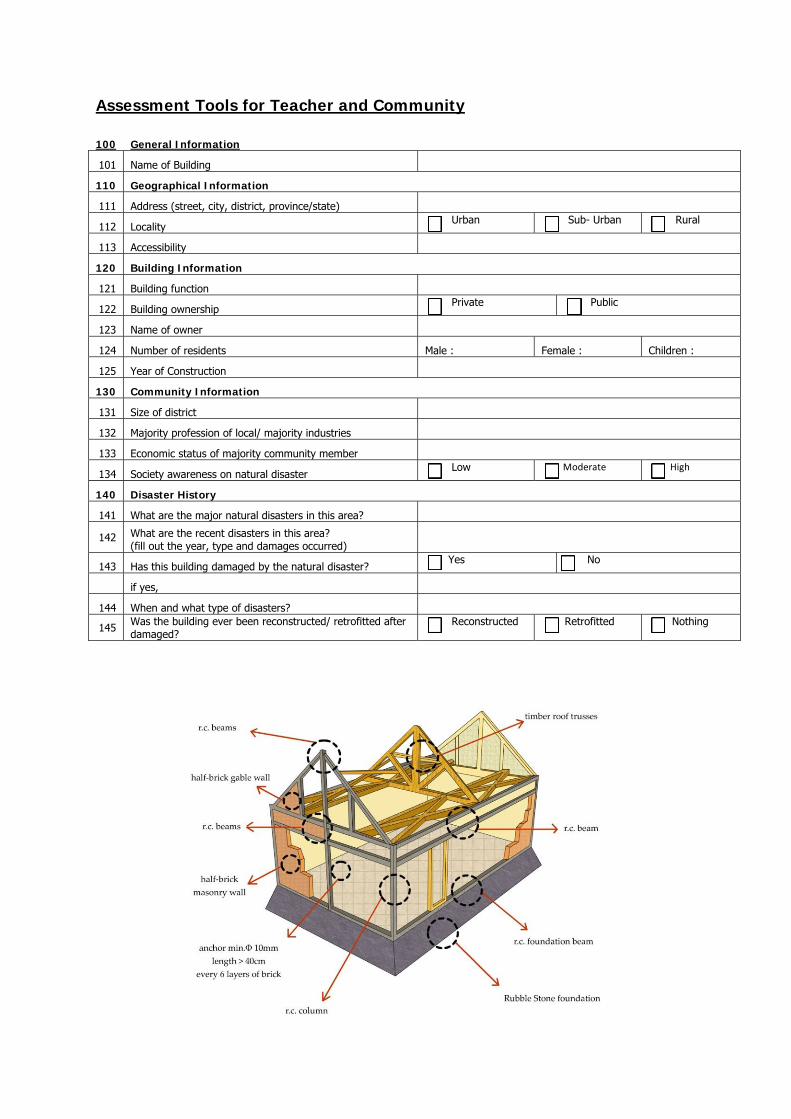
Assessment Tools for Teacher and Community
100 General Information
101 Name of Building
110 Geographical Information
111 Address (street, city, district, province/state)
112 Locality Urban Sub- Urban Rural
113 Accessibility
120 Building Information
121 Building function
122 Building ownership Private Public
123 Name of owner
124 Number of residents Male : Female : Children :
125 Year of Construction
130 Community Information
131 Size of district
132 Majority profession of local/ majority industries
133 Economic status of majority community member
134 Society awareness on natural disaster Low Moderate High
140 Disaster History
141 What are the major natural disasters in this area?
142 What are the recent disasters in this area? (fill out the year, type and damages occurred)
143 Has this building damaged by the natural disaster? Yes No
if yes,
144 When and what type of disasters?
145 Was the building ever been reconstructed/ retrofitted after damaged?
Reconstructed Retrofitted Nothing
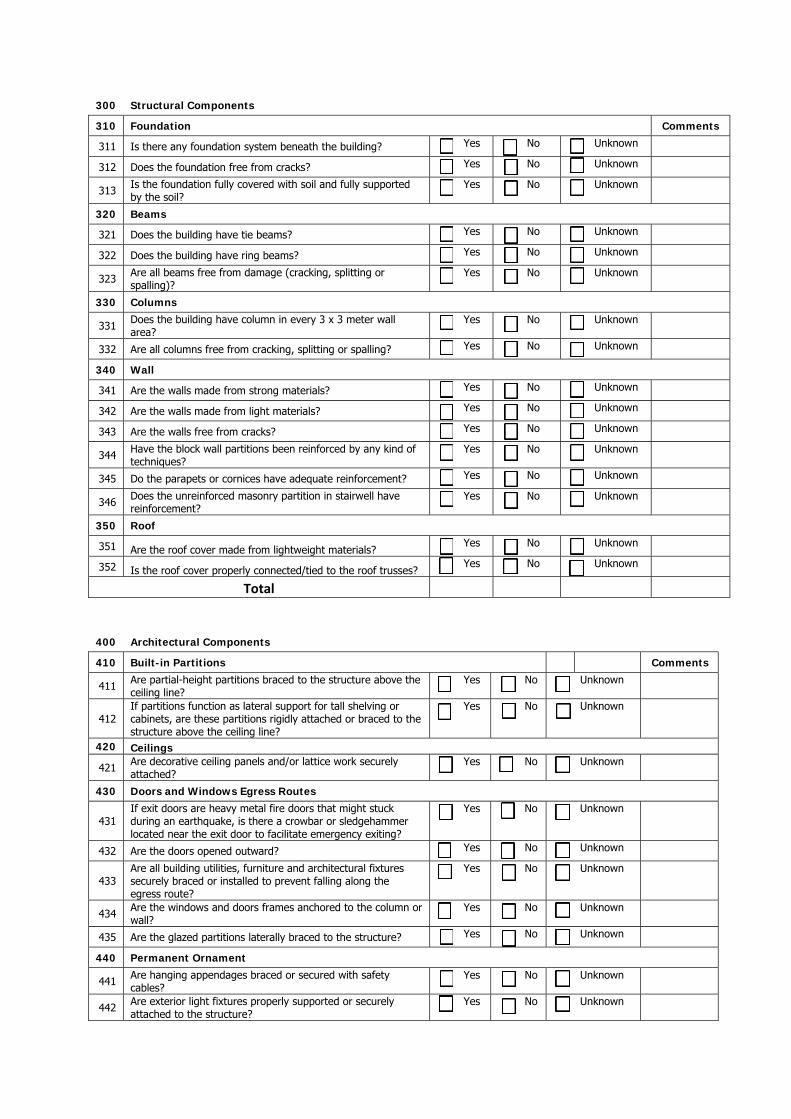
300 Structural Components 310 Foundation Comments
311 Is there any foundation system beneath the building? Yes No Unknown 312 Does the foundation free from cracks? Yes No Unknown
313 Is the foundation fully covered with soil and fully supported by the soil?
Yes No Unknown
320 Beams
321 Does the building have tie beams? Yes No Unknown
322 Does the building have ring beams? Yes No Unknown
323 Are all beams free from damage (cracking, splitting or spalling)?
Yes No Unknown
330 Columns
331 Does the building have column in every 3 x 3 meter wall area?
Yes No Unknown
332 Are all columns free from cracking, splitting or spalling? Yes No Unknown 340 Wall
341 Are the walls made from strong materials? Yes No Unknown 342 Are the walls made from light materials? Yes No Unknown 343 Are the walls free from cracks? Yes No Unknown
344 Have the block wall partitions been reinforced by any kind of techniques?
Yes No Unknown
345 Do the parapets or cornices have adequate reinforcement? Yes No Unknown
346 Does the unreinforced masonry partition in stairwell have reinforcement?
Yes No Unknown
350 Roof
351 Are the roof cover made from lightweight materials? Yes No Unknown
352 Is the roof cover properly connected/tied to the roof trusses? Yes No Unknown
Total
400 Architectural Components 410 Built-in Partitions Comments
411 Are partial-height partitions braced to the structure above the ceiling line?
Yes No Unknown
412 If partitions function as lateral support for tall shelving or cabinets, are these partitions rigidly attached or braced to the structure above the ceiling line?
Yes No Unknown
420 Ceilings
421 Are decorative ceiling panels and/or lattice work securely attached?
Yes No Unknown
430 Doors and Windows Egress Routes
431 If exit doors are heavy metal fire doors that might stuck during an earthquake, is there a crowbar or sledgehammer located near the exit door to facilitate emergency exiting?
Yes
No Unknown
432 Are the doors opened outward? Yes No Unknown
433 Are all building utilities, furniture and architectural fixtures securely braced or installed to prevent falling along the egress route?
Yes No Unknown
434 Are the windows and doors frames anchored to the column or wall?
Yes No Unknown
435 Are the glazed partitions laterally braced to the structure? Yes No Unknown 440 Permanent Ornament
441 Are hanging appendages braced or secured with safety cables?
Yes No Unknown
442 Are exterior light fixtures properly supported or securely attached to the structure?
Yes No Unknown
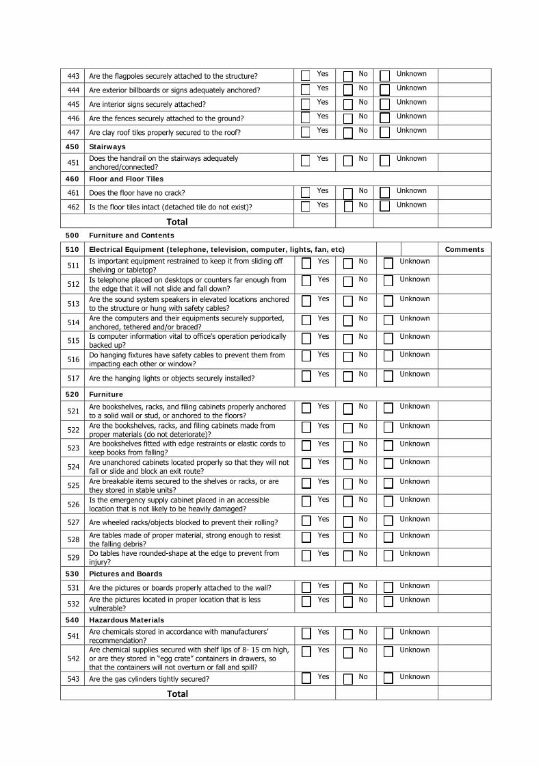
443 Are the flagpoles securely attached to the structure? Yes No Unknown 444 Are exterior billboards or signs adequately anchored? Yes No Unknown 445 Are interior signs securely attached? Yes No Unknown 446 Are the fences securely attached to the ground? Yes No Unknown 447 Are clay roof tiles properly secured to the roof? Yes No Unknown 450 Stairways
451 Does the handrail on the stairways adequately anchored/connected?
Yes No Unknown
460 Floor and Floor Tiles
461 Does the floor have no crack? Yes No Unknown
462 Is the floor tiles intact (detached tile do not exist)? Yes No Unknown Total
500 Furniture and Contents 510 Electrical Equipment (telephone, television, computer, lights, fan, etc) Comments
511 Is important equipment restrained to keep it from sliding off shelving or tabletop?
Yes No Unknown
512 Is telephone placed on desktops or counters far enough from the edge that it will not slide and fall down?
Yes No Unknown
513 Are the sound system speakers in elevated locations anchored to the structure or hung with safety cables?
Yes No Unknown
514 Are the computers and their equipments securely supported, anchored, tethered and/or braced?
Yes No Unknown
515 Is computer information vital to office's operation periodically backed up?
Yes No Unknown
516 Do hanging fixtures have safety cables to prevent them from impacting each other or window?
Yes No Unknown
517 Are the hanging lights or objects securely installed? Yes No Unknown
520 Furniture
521 Are bookshelves, racks, and filing cabinets properly anchored to a solid wall or stud, or anchored to the floors?
Yes No Unknown
522 Are the bookshelves, racks, and filing cabinets made from proper materials (do not deteriorate)?
Yes No Unknown
523 Are bookshelves fitted with edge restraints or elastic cords to keep books from falling?
Yes No Unknown
524 Are unanchored cabinets located properly so that they will not fall or slide and block an exit route?
Yes No Unknown
525 Are breakable items secured to the shelves or racks, or are they stored in stable units?
Yes No Unknown
526 Is the emergency supply cabinet placed in an accessible location that is not likely to be heavily damaged?
Yes No Unknown
527 Are wheeled racks/objects blocked to prevent their rolling? Yes No Unknown
528 Are tables made of proper material, strong enough to resist the falling debris?
Yes No Unknown
529 Do tables have rounded-shape at the edge to prevent from injury?
Yes No Unknown
530 Pictures and Boards
531 Are the pictures or boards properly attached to the wall? Yes No Unknown
532 Are the pictures located in proper location that is less vulnerable?
Yes No Unknown
540 Hazardous Materials
541 Are chemicals stored in accordance with manufacturers’ recommendation?
Yes No Unknown
542 Are chemical supplies secured with shelf lips of 8- 15 cm high, or are they stored in “egg crate” containers in drawers, so that the containers will not overturn or fall and spill?
Yes No Unknown
543 Are the gas cylinders tightly secured? Yes No Unknown
Total
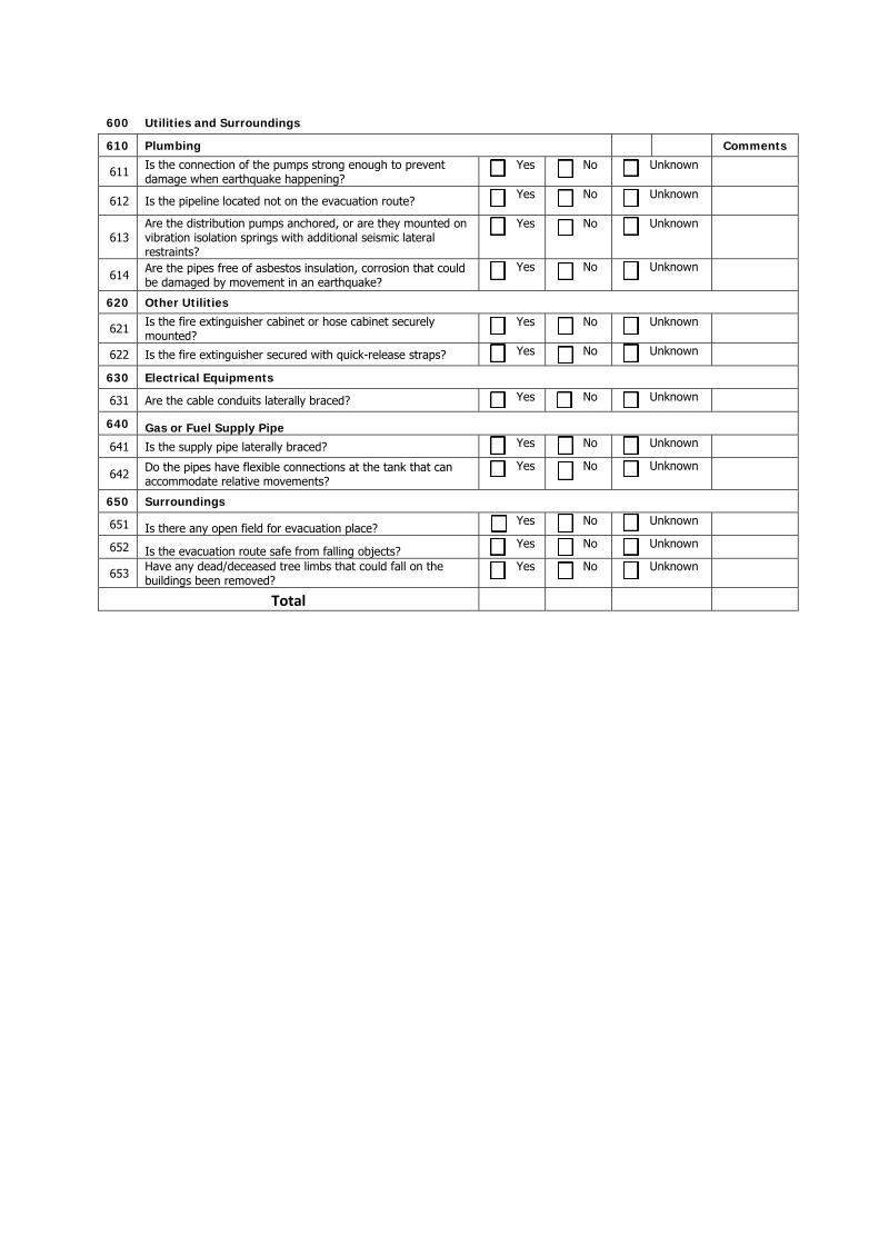
600 Utilities and Surroundings 610 Plumbing Comments
611 Is the connection of the pumps strong enough to prevent damage when earthquake happening?
Yes No Unknown
612 Is the pipeline located not on the evacuation route? Yes No Unknown
613 Are the distribution pumps anchored, or are they mounted on vibration isolation springs with additional seismic lateral restraints?
Yes No Unknown
614 Are the pipes free of asbestos insulation, corrosion that could be damaged by movement in an earthquake?
Yes No Unknown
620 Other Utilities
621 Is the fire extinguisher cabinet or hose cabinet securely mounted?
Yes No Unknown
622 Is the fire extinguisher secured with quick-release straps? Yes No Unknown 630 Electrical Equipments
631 Are the cable conduits laterally braced? Yes No Unknown 640 Gas or Fuel Supply Pipe
641 Is the supply pipe laterally braced? Yes No Unknown
642 Do the pipes have flexible connections at the tank that can accommodate relative movements?
Yes No Unknown
650 Surroundings
651 Is there any open field for evacuation place? Yes No Unknown
652 Is the evacuation route safe from falling objects? Yes No Unknown
653 Have any dead/deceased tree limbs that could fall on the buildings been removed?
Yes No Unknown
Total
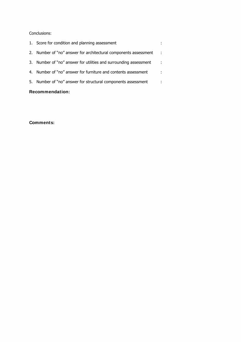
Conclusions:
1. Score for condition and planning assessment :
2. Number of “no” answer for architectural components assessment :
3. Number of “no” answer for utilities and surrounding assessment :
4. Number of “no” answer for furniture and contents assessment :
5. Number of “no” answer for structural components assessment :
Recommendation:
Comments:
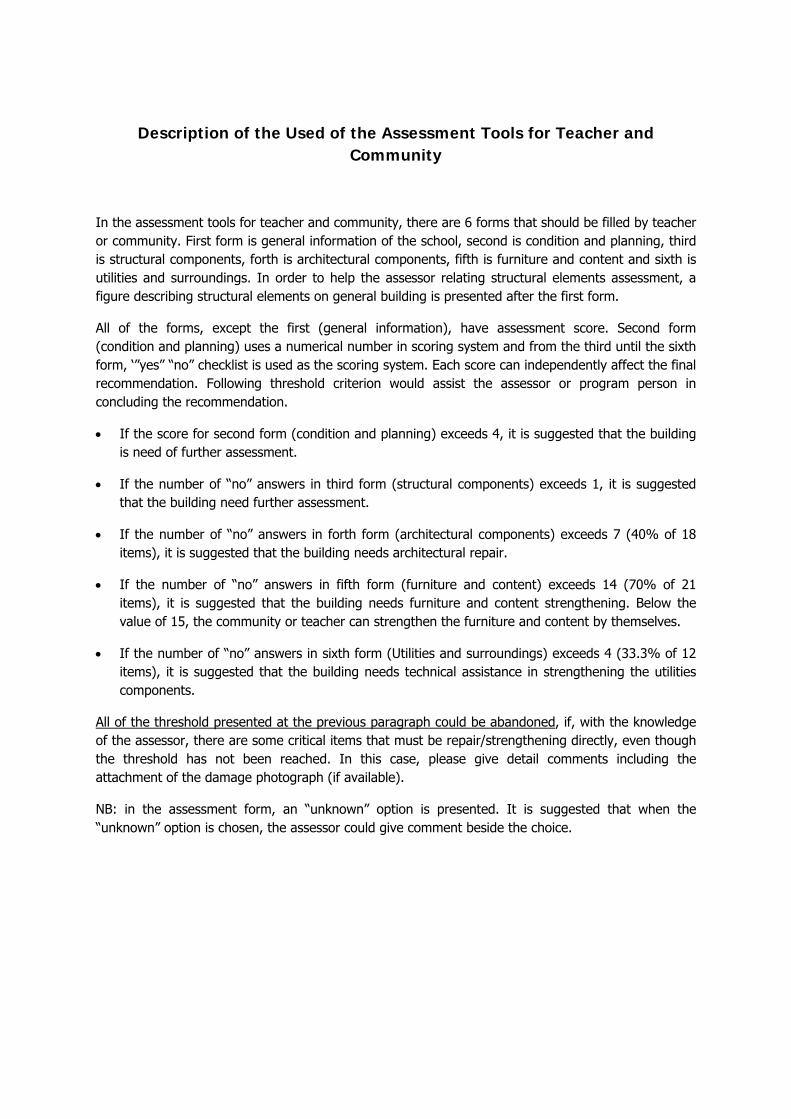
Description of the Used of the Assessment Tools for Teacher and
Community
In the assessment tools for teacher and community, there are 6 forms that should be filled by teacher or community. First form is general information of the school, second is condition and planning, third is structural components, forth is architectural components, fifth is furniture and content and sixth is utilities and surroundings. In order to help the assessor relating structural elements assessment, a figure describing structural elements on general building is presented after the first form.
All of the forms, except the first (general information), have assessment score. Second form (condition and planning) uses a numerical number in scoring system and from the third until the sixth form, ‘”yes” “no” checklist is used as the scoring system. Each score can independently affect the final recommendation. Following threshold criterion would assist the assessor or program person in concluding the recommendation.
• If the score for second form (condition and planning) exceeds 4, it is suggested that the building is need of further assessment.
• If the number of “no” answers in third form (structural components) exceeds 1, it is suggested that the building need further assessment.
• If the number of “no” answers in forth form (architectural components) exceeds 7 (40% of 18 items), it is suggested that the building needs architectural repair.
• If the number of “no” answers in fifth form (furniture and content) exceeds 14 (70% of 21 items), it is suggested that the building needs furniture and content strengthening. Below the value of 15, the community or teacher can strengthen the furniture and content by themselves.
• If the number of “no” answers in sixth form (Utilities and surroundings) exceeds 4 (33.3% of 12 items), it is suggested that the building needs technical assistance in strengthening the utilities components.
All of the threshold presented at the previous paragraph could be abandoned, if, with the knowledge of the assessor, there are some critical items that must be repair/strengthening directly, even though the threshold has not been reached. In this case, please give detail comments including the attachment of the damage photograph (if available).
NB: in the assessment form, an “unknown” option is presented. It is suggested that when the “unknown” option is chosen, the assessor could give comment beside the choice.
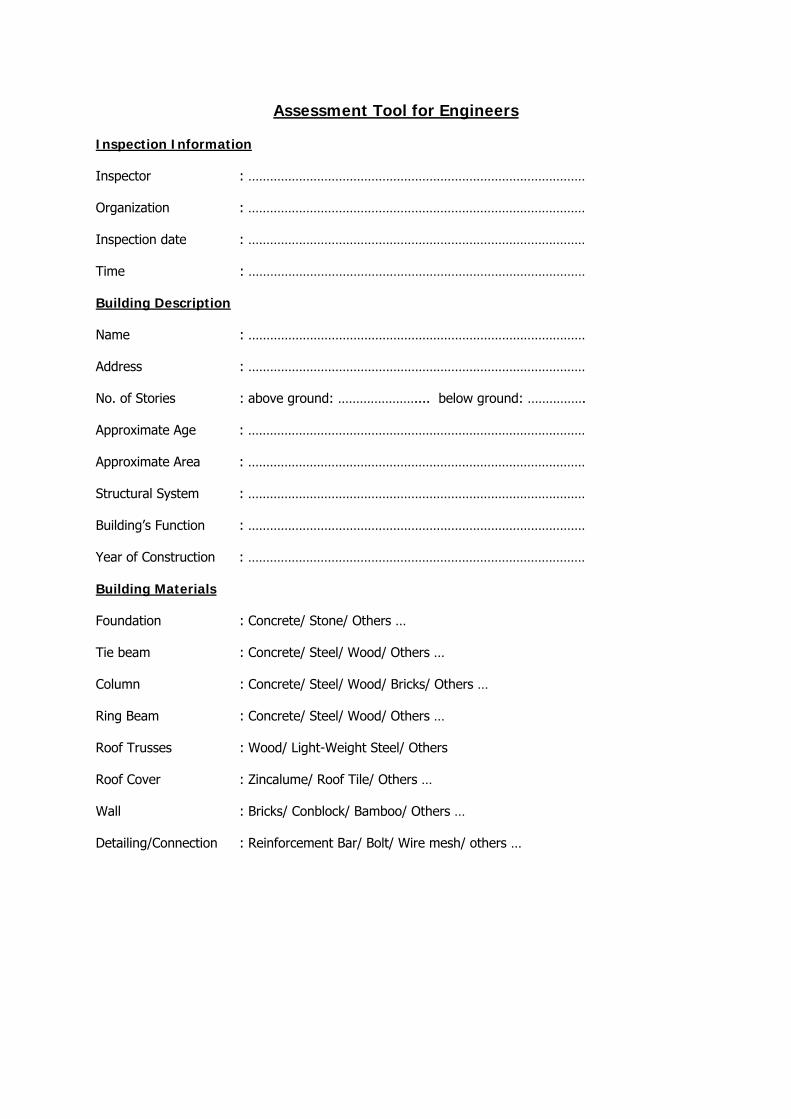
Assessment Tool for Engineers
Inspection Information
Inspector : …………………………………………………………………………………
Organization : …………………………………………………………………………………
Inspection date : …………………………………………………………………………………
Time : …………………………………………………………………………………
Building Description
Name : …………………………………………………………………………………
Address : …………………………………………………………………………………
No. of Stories : above ground: ………………….... below ground: …………….
Approximate Age : …………………………………………………………………………………
Approximate Area : …………………………………………………………………………………
Structural System : …………………………………………………………………………………
Building’s Function : …………………………………………………………………………………
Year of Construction : …………………………………………………………………………………
Building Materials
Foundation : Concrete/ Stone/ Others …
Tie beam : Concrete/ Steel/ Wood/ Others …
Column : Concrete/ Steel/ Wood/ Bricks/ Others …
Ring Beam : Concrete/ Steel/ Wood/ Others …
Roof Trusses : Wood/ Light-Weight Steel/ Others
Roof Cover : Zincalume/ Roof Tile/ Others …
Wall : Bricks/ Conblock/ Bamboo/ Others …
Detailing/Connection : Reinforcement Bar/ Bolt/ Wire mesh/ others …
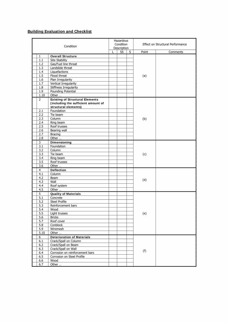
Building Evaluation and Checklist
Condition
Hazardous Condition
Description Effect on Structural Performance
L SS S Point Comments 1 Overall Structure
(a)
1.1 Site Stability 1.2 Gas/Fuel line threat 1.3 Landslide threat 1.4 Liquefactions 1.5 Flood threat 1.6 Plan Irregularity 1.7 Vertical Irregularity 1.8 Stiffness Irregularity 1.9 Pounding Potential 1.10 Other … 2 Existing of Structural Elements
(including the sufficient amount of structural elements)
(b)
2.1 Foundation 2.2 Tie beam 2.3 Column 2.4 Ring beam 2.5 Roof trusses 2.6 Bearing wall 2.7 Bracing 2.8 Other … 3 Dimensioning
(c)
3.1 Foundation 3.2 Column 3.3 Tie beam 3.4 Ring beam 3.5 Roof trusses 3.6 Other … 4 Deflection
(d)
4.1 Column 4.2 Beam 4.3 Wall 4.4 Roof system 4.5 Other … 5 Quality of Materials
(e)
5.1 Concrete 5.2 Steel Profile 5.3 Reinforcement bars 5.4 Wood 5.5 Light trusses 5.6 Bricks 5.7 Roof cover 5.8 Conblock 5.9 Wiremesh 5.10 Other … 6 Deterioration of Materials
(f)
6.1 Crack/Spall on Column 6.2 Crack/Spall on Beam 6.3 Crack/Spall on Wall 6.4 Corrosion on reinforcement bars 6.5 Corrosion on Steel Profile 6.6 Wood 6.7 Other …
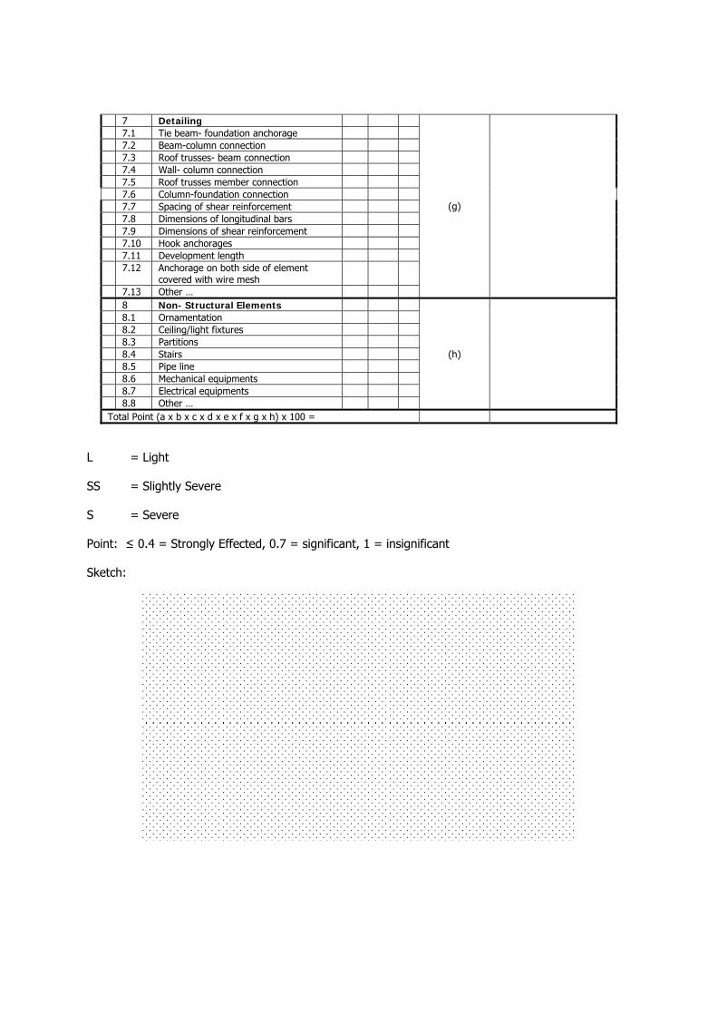
7 Detailing
(g)
7.1 Tie beam- foundation anchorage 7.2 Beam-column connection 7.3 Roof trusses- beam connection 7.4 Wall- column connection 7.5 Roof trusses member connection 7.6 Column-foundation connection 7.7 Spacing of shear reinforcement 7.8 Dimensions of longitudinal bars 7.9 Dimensions of shear reinforcement 7.10 Hook anchorages 7.11 Development length 7.12 Anchorage on both side of element
covered with wire mesh
7.13 Other … 8 Non- Structural Elements
(h)
8.1 Ornamentation 8.2 Ceiling/light fixtures 8.3 Partitions 8.4 Stairs 8.5 Pipe line 8.6 Mechanical equipments 8.7 Electrical equipments 8.8 Other … Total Point (a x b x c x d x e x f x g x h) x 100 =
L = Light
SS = Slightly Severe
S = Severe
Point: ≤ 0.4 = Strongly Effected, 0.7 = significant, 1 = insignificant
Sketch:

Summary Recommendations:
Comments:
Description of the Use of Assessment Tool for Engineers
The first page of the assessment tool contains the general information of the building. The general information considered consists of the information of the structural system, building’s material, building’s function, building’s age, building’s area, and number of story.
1. Structural system and building’s material will give general description of the building load resisting element, either vertical or horizontal resisting elements.
2. Building’s function, number of story and building’s area will give general description of the approximate load apply to the building and the complexity.
3. Building’s age will give general description on the building codes used on the design and possibilities of material deterioration.
In the second and third page of the assessment tool, there are eight (8) general criteria that will help the engineer to assess the vulnerability of the building. The eight general criteria is overall structural condition, existing of structural elements, dimensioning, deflection, quality of materials, deterioration of materials, detailing, and non-structural elements hazard.
Each criterion consists of some parameters that will help the engineer to assign the point for each criterion. Engineer should assess the condition of each parameters based on the existing condition of the structure. From the condition of each parameter, the engineer should able to judge the point assigned to the each criteria.
It should be noticed that when the engineers decide to assign the point equal to zero (0). It means that retrofit/ rebuild the building is technically strongly recommended, even in other criteria the engineer assign 1 for it. When the point is 1, it means that the building will fine.
After each criterion has the point, the engineer should multiply all the point from the criteria as total point and multiply it by 100. If the total point is 100, it means that the building is totally safe. If the total point is between 2.56– 100, it means that retrofitting is suggested. If the total point is between 0- 2.56, it means that rebuild/ retrofit is highly recommended.
100 = Safe
2.56-100 = retrofit the building
0 – 2.56 = rebuild/ retrofit the building (more than 50% of the building is strongly damaged).
After reviewing the total point, the engineer concludes the assessment in a recommendation whether to retrofit the building, rebuild the building, or do nothing. A sketch of the condition of important features found in the assessment could be drawn on the place available.

Assessment Tools for Program Person
Inspection Information
Name : ……………………………………………………...
Date : ……………………………………………………...
Building Information
Location : ……………………………………………………...
Function : ……………………………………………………...
Number of occupant/user : ……………………………………………………...
Number of building : ……………………………………………………...
Age of the building : ……………………………………………………...
Latest repair/retrofit (year) : ……………………………………………………...
Impacts on Other Fields Yes No Comments
1 Does the building have historical values?
2 Does the retrofitting entail social disruption?
3 Does the damage on the building harm the surrounding community?
Pre-Disaster and Post Disaster Function
4 Does the building contribute to community well-being/ public interest?
5 Does the building act as temporary emergency shelter in post-disaster measures?
Budgeting and Benefit
6 Does the budget available enough to carry out retrofitting techniques proposed?
7 Does the budget available enough for regular maintenance?
8 Does the retrofitting approach give more benefit compare to rebuild the building?
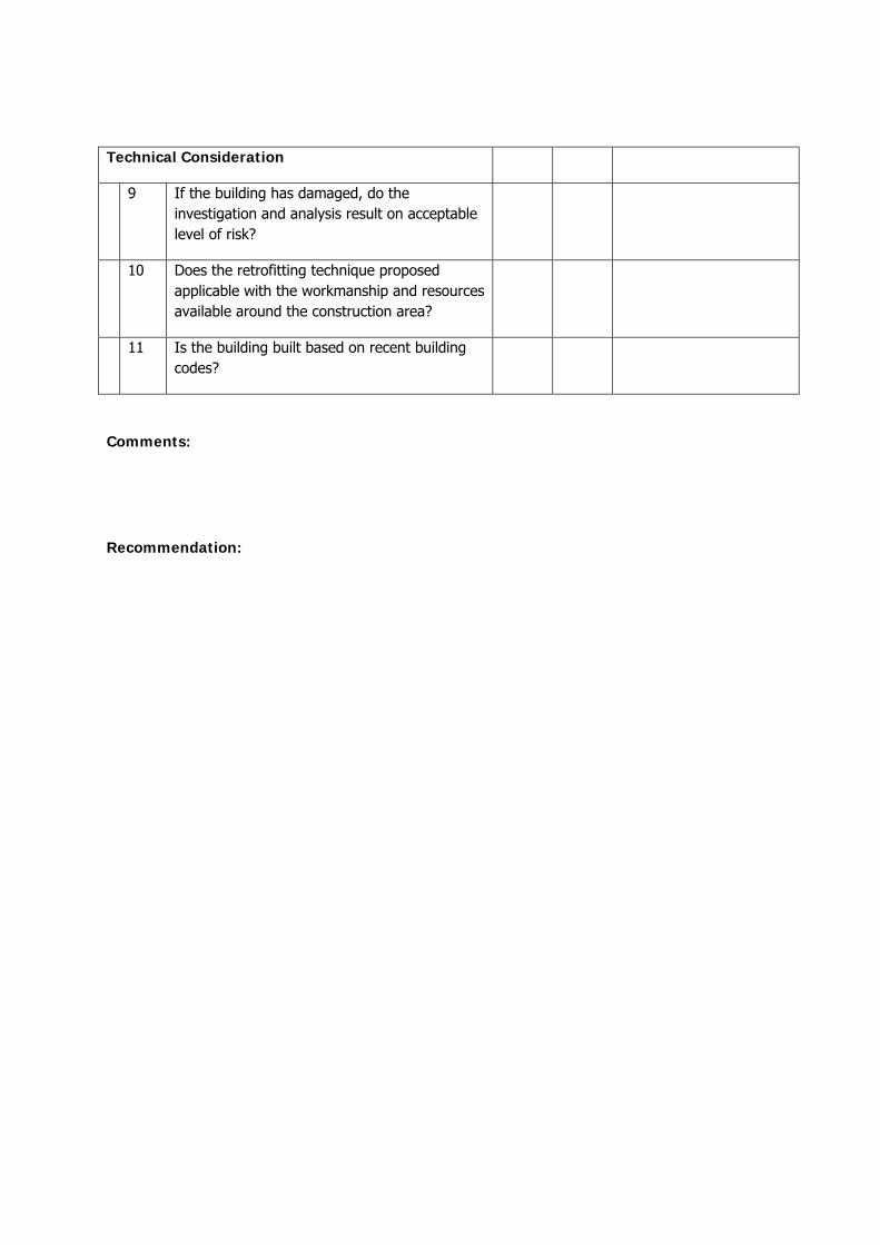
Technical Consideration
9 If the building has damaged, do the investigation and analysis result on acceptable level of risk?
10 Does the retrofitting technique proposed applicable with the workmanship and resources available around the construction area?
11 Is the building built based on recent building codes?
Comments:
Recommendation:
REFERENCES
Pribadi, Krishna S.; Kusumastuti, Dyah; Handayani, Nurita; Edwin. Panduan Konstruksi dan Perkuatan Bangunan Sekolah Tahan Gempa. CDM-ITB. 2008
FEMA 172. NEHRP Handbook of Techniques for the Seismic Rehabilitation of Existing Buildings
FEMA 74. Reducing the Risks of Nonstructural Earthquake Damage-A Practical Guide
Dowrick, David. Earthquake Risk Reduction. Wiley. 2003
Kusumastuti, Dyah & Handayani, Nurita. Pedoman Mitigasi Fisik untuk Sekolah Melindungi Siswa Dari Bencana Gempabumi. CDM-ITB Supported by AUS-AID. 2008
Tomazevic, Miha. Earthquake Resistant Design of Masonry Buildings. Imperial College Press. 1999
Arya, Anand S. Guidelines for Earthquake Resistant Design, Construction, and Retrofitting of Buildings
in Afganishtan. MUDH in collaboration with UNCRD. 2003