Embed Size (px)
Citation preview
Manual of AestheticDesign
Practice
Manual of AestheticDesign
Practice
Table of Contents
A Introduction . . . . . . . . . . . . . . . . . . . . . . . . . . . . . . . . . . . . . . . . . . . . . . . . . . . . . . . . . . .1
How to Use This Manual . . . . . . . . . . . . . . . . . . . . . . . . . . . . . . . . . . . . . . . . . . . . . . . . . . . . .4
Aesthetic Design Method . . . . . . . . . . . . . . . . . . . . . . . . . . . . . . . . . . . . . . . . . . . . . . . . . . . . .5
B Aesthetic Classification System . . . . . . . . . . . . . . . . . . . . . . . . . . . . . . . . . . . . . . . . . . . . . . . . .9
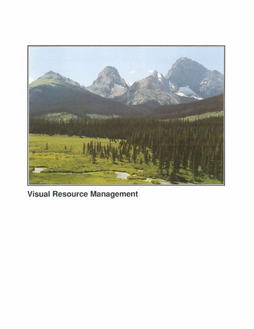
C Visual Resource Management . . . . . . . . . . . . . . . . . . . . . . . . . . . . . . . . . . . . . . . . . . . . . . . . .11
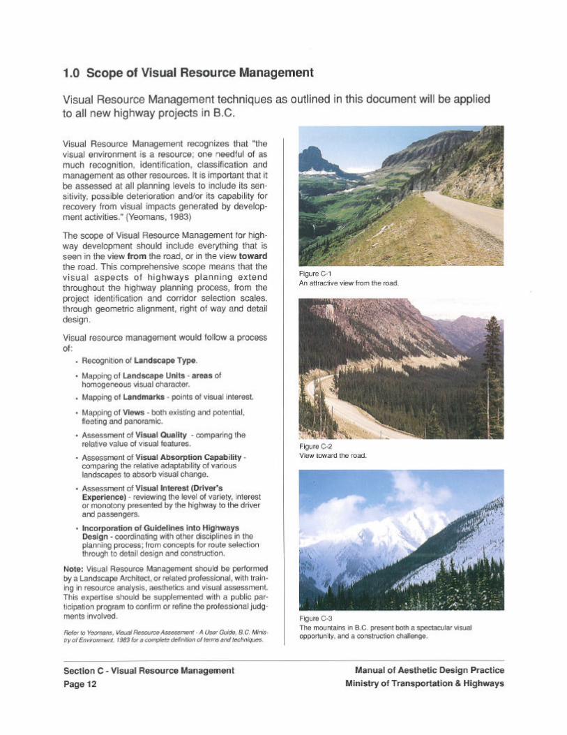
1.0 Scope of Visual Resource Management . . . . . . . . . . . . . . . . . . . . . . . . . . . . . . . . . . . .12
2.0 Landscapes of British Columbia . . . . . . . . . . . . . . . . . . . . . . . . . . . . . . . . . . . . . . . . . .13
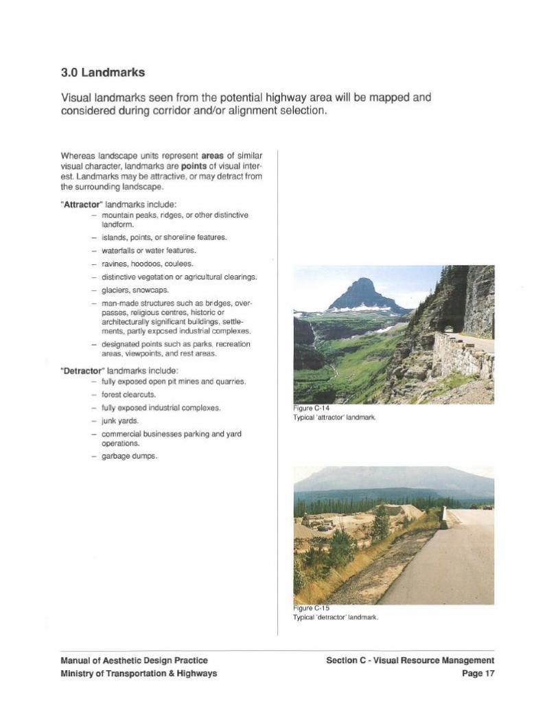
3.0 Landmarks . . . . . . . . . . . . . . . . . . . . . . . . . . . . . . . . . . . . . . . . . . . . . . . . . . . . . . . . . . .17
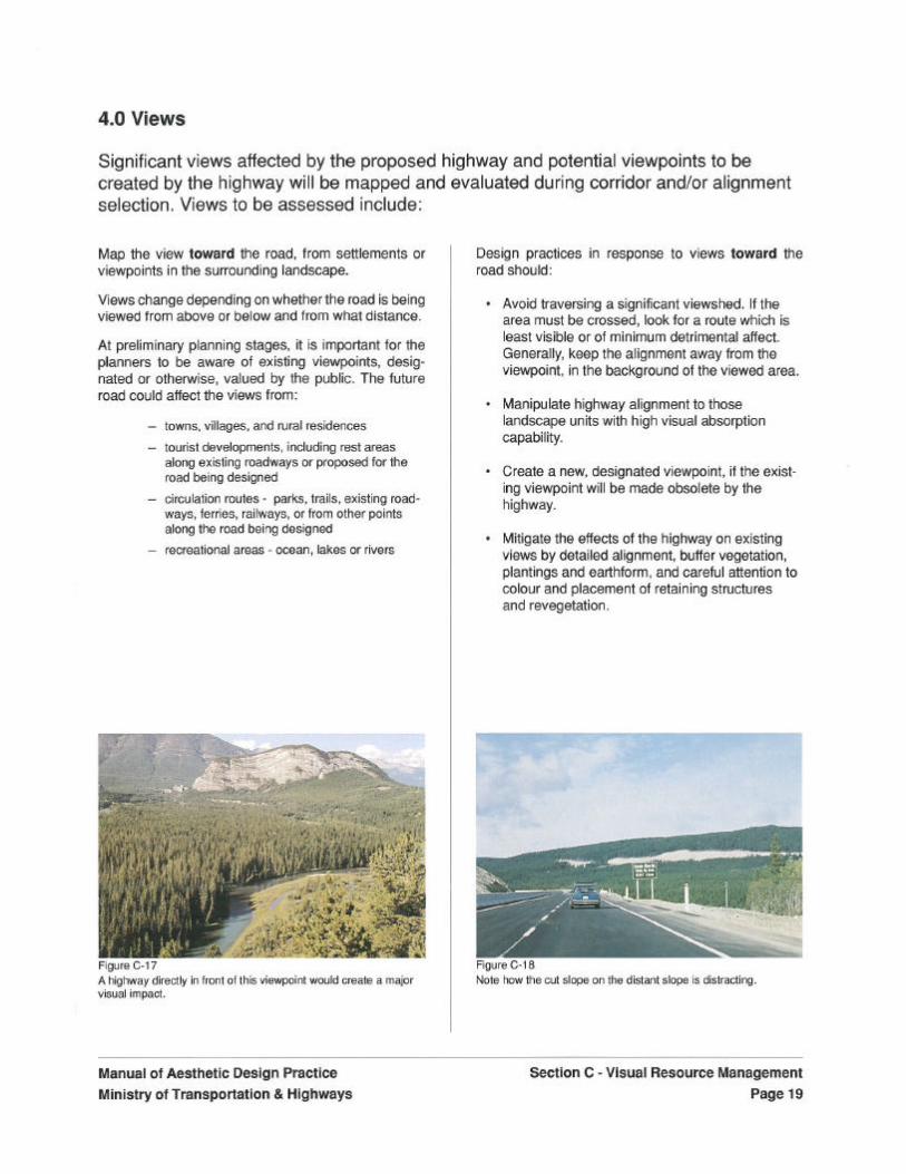
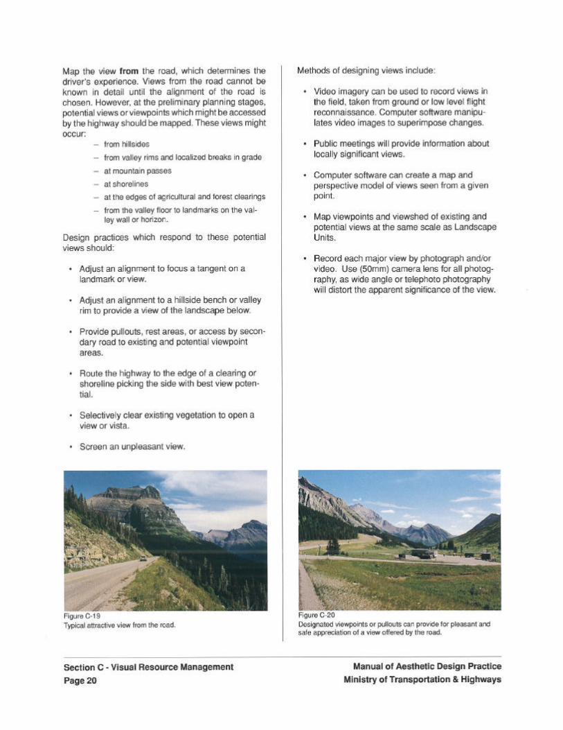
4.0 Views . . . . . . . . . . . . . . . . . . . . . . . . . . . . . . . . . . . . . . . . . . . . . . . . . . . . . . . . . . . . . . .19
5.0 Visual Quality Assessment . . . . . . . . . . . . . . . . . . . . . . . . . . . . . . . . . . . . . . . . . . . . . .21
6.0 Visual Absorption Capability . . . . . . . . . . . . . . . . . . . . . . . . . . . . . . . . . . . . . . . . . . . . .23
7.0 Visual Interest: The Driver’s Experience
8.0 Integration of Guidelines into Highway Design . . . . . . . . . . . . . . . . . . . . . . . . . . . . . . .28
D Alignment . . . . . . . . . . . . . . . . . . . . . . . . . . . . . . . . . . . . . . . . . . . . . . . . . . . . . . . . . . . . . . . . . .31
1.0 Integration of Alignment
2.0 Response to Topography
3.0 Driver Interest and Experience . . . . . . . . . . . . . . . . . . . . . . . . . . . . . . . . . . . . . . . . . . .38
4.0 Confusing Alignment . . . . . . . . . . . . . . . . . . . . . . . . . . . . . . . . . . . . . . . . . . . . . . . . . . .39
5.0 Safety . . . . . . . . . . . . . . . . . . . . . . . . . . . . . . . . . . . . . . . . . . . . . . . . . . . . . . . . . . . . . .41
6.0 Response to Views . . . . . . . . . . . . . . . . . . . . . . . . . . . . . . . . . . . . . . . . . . . . . . . . . . . .43i
7.0 Response to Vegetation . . . . . . . . . . . . . . . . . . . . . . . . . . . . . . . . . . . . . . . . . . . . . . . .48
8.0 Secondary Aesthetic Impacts - Climate . . . . . . . . . . . . . . . . . . . . . . . . . . . . . . . . . . . .49
9.0 Secondary Aesthetic Impacts - Ecosystems . . . . . . . . . . . . . . . . . . . . . . . . . . . . . . . . .50
10.0 Secondary Aesthetic Impacts - Adjacent Land Use . . . . . . . . . . . . . . . . . . . . . . . . . . .51
E Clearing and Grubbing – Vegetation Management . . . . . . . . . . . . . . . . . . . . . . . . . . . . . . . . .53
1.0 Location of Disposal Areas . . . . . . . . . . . . . . . . . . . . . . . . . . . . . . . . . . . . . . . . . . . . . .54
2.0 Method of Clearing . . . . . . . . . . . . . . . . . . . . . . . . . . . . . . . . . . . . . . . . . . . . . . . . . . . .55
3.0 Limits of Clearing . . . . . . . . . . . . . . . . . . . . . . . . . . . . . . . . . . . . . . . . . . . . . . . . . . . . .56
4.0 Selective Clearing . . . . . . . . . . . . . . . . . . . . . . . . . . . . . . . . . . . . . . . . . . . . . . . . . . . . .58
5.0 Clearing of Roadside Facility Areas . . . . . . . . . . . . . . . . . . . . . . . . . . . . . . . . . . . . . . .64
F Earthworks . . . . . . . . . . . . . . . . . . . . . . . . . . . . . . . . . . . . . . . . . . . . . . . . . . . . . . . . . . . . . . . . .67
1.0 Location of Borrow Pits, Surplus Disposal, Ponds, and Basins . . . . . . . . . . . . . . . . . .68
2.0 Site Preparation . . . . . . . . . . . . . . . . . . . . . . . . . . . . . . . . . . . . . . . . . . . . . . . . . . . . . .70
3.0 Integration with Adjacent Topography . . . . . . . . . . . . . . . . . . . . . . . . . . . . . . . . . . . . . .71
4.0 Application of Earthwork Guidelines . . . . . . . . . . . . . . . . . . . . . . . . . . . . . . . . . . . . . . .74
Manual of Aesthetic Design Practice – Table of Contents Page i
G Revegetation – Vegetation Management . . . . . . . . . . . . . . . . . . . . . . . . . . . . . . . . . . . . . . . . .83
1.0 Site Preparation . . . . . . . . . . . . . . . . . . . . . . . . . . . . . . . . . . . . . . . . . . . . . . . . . . . . . .84
2.0 Operational Safety Distances . . . . . . . . . . . . . . . . . . . . . . . . . . . . . . . . . . . . . . . . . . . .85
3.0 Response to Views from the Road . . . . . . . . . . . . . . . . . . . . . . . . . . . . . . . . . . . . . . . .86
4.0 Response to Views Toward the Road . . . . . . . . . . . . . . . . . . . . . . . . . . . . . . . . . . . . . .91
5.0 Response to Natural Vegetation . . . . . . . . . . . . . . . . . . . . . . . . . . . . . . . . . . . . . . . . . .92
6.0 Response to Erosion . . . . . . . . . . . . . . . . . . . . . . . . . . . . . . . . . . . . . . . . . . . . . . . . . . .94
7.0 Response to Climatic Conditions . . . . . . . . . . . . . . . . . . . . . . . . . . . . . . . . . . . . . . . . .96
H Roadway Structures . . . . . . . . . . . . . . . . . . . . . . . . . . . . . . . . . . . . . . . . . . . . . . . . . . . . . . . . .99
1.0 Aesthetic Classification System . . . . . . . . . . . . . . . . . . . . . . . . . . . . . . . . . . . . . . . . .100
2.0 Integration of Structures . . . . . . . . . . . . . . . . . . . . . . . . . . . . . . . . . . . . . . . . . . . . . . .101
3.0 Location of Structures . . . . . . . . . . . . . . . . . . . . . . . . . . . . . . . . . . . . . . . . . . . . . . . . .102
4.0 Scale of Structures . . . . . . . . . . . . . . . . . . . . . . . . . . . . . . . . . . . . . . . . . . . . . . . . . . .103
5.0 Form of Structures . . . . . . . . . . . . . . . . . . . . . . . . . . . . . . . . . . . . . . . . . . . . . . . . . . .104
6.0 Colour of Structures . . . . . . . . . . . . . . . . . . . . . . . . . . . . . . . . . . . . . . . . . . . . . . . . . .105
7.0 Texture of Structures . . . . . . . . . . . . . . . . . . . . . . . . . . . . . . . . . . . . . . . . . . . . . . . . . .106
8.0 Unity of Structures . . . . . . . . . . . . . . . . . . . . . . . . . . . . . . . . . . . . . . . . . . . . . . . . . . . .107
9.0 Accents . . . . . . . . . . . . . . . . . . . . . . . . . . . . . . . . . . . . . . . . . . . . . . . . . . . . . . . . . . . .108
10.0 Guidelines . . . . . . . . . . . . . . . . . . . . . . . . . . . . . . . . . . . . . . . . . . . . . . . . . . . . . . . . . .109
I Roadside Facilities . . . . . . . . . . . . . . . . . . . . . . . . . . . . . . . . . . . . . . . . . . . . . . . . . . . . . . . . . .123
1.0 Provincial Roadside Facility Program . . . . . . . . . . . . . . . . . . . . . . . . . . . . . . . . . . . . .124
2.0 Definitions of Roadside Facility Types . . . . . . . . . . . . . . . . . . . . . . . . . . . . . . . . . . . .125
3.0 Aesthetic Classification System and Roadside Facilities . . . . . . . . . . . . . . . . . . . . . .130
4.0 Roadside Facility Spacing Plan . . . . . . . . . . . . . . . . . . . . . . . . . . . . . . . . . . . . . . . . .131
5.0 Roadside Facility Site Selection Process . . . . . . . . . . . . . . . . . . . . . . . . . . . . . . . . . .132
6.0 Roadside Facility Design Process . . . . . . . . . . . . . . . . . . . . . . . . . . . . . . . . . . . . . . .136
7.0 Use of Professionals . . . . . . . . . . . . . . . . . . . . . . . . . . . . . . . . . . . . . . . . . . . . . . . . . .143
8.0 Summary of Roadside Facility Planning and Design Method . . . . . . . . . . . . . . . . . . .144
J Above Ground Utilities . . . . . . . . . . . . . . . . . . . . . . . . . . . . . . . . . . . . . . . . . . . . . . . . . . . . . .145
1.0 Scale of Structure . . . . . . . . . . . . . . . . . . . . . . . . . . . . . . . . . . . . . . . . . . . . . . . . . . . .146
2.0 Location of Utility Structures . . . . . . . . . . . . . . . . . . . . . . . . . . . . . . . . . . . . . . . . . . . .147
3.0 Integration with Adjacent Vegetation and Earthwork
4.0 Type, Placement, and Level of Illumination . . . . . . . . . . . . . . . . . . . . . . . . . . . . . . . .150
5.0 Artistic Application of Lighting . . . . . . . . . . . . . . . . . . . . . . . . . . . . . . . . . . . . . . . . . . .151
References . . . . . . . . . . . . . . . . . . . . . . . . . . . . . . . . . . . . . . . . . . . . . . . . . . . . . . . . . . . . . . . .153
List of Figures . . . . . . . . . . . . . . . . . . . . . . . . . . . . . . . . . . . . . . . . . . . . . . . . . . . . . . . . . . . . .155
Manual of Aesthetic Design Practice – Table of Contents Page ii

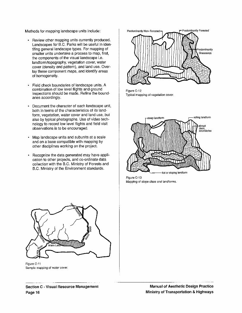
Methods for mapping landscape units include:
* Review other mapping units currently produced. Landscapes for B.C. Parks will be useful in iden- tifing general landscape types. For mapping of smaller units undertake a process to map, first, the components of the visual landscape i.e. landformitopography, vegetation cover, water cover (density and pattern), and land use. Over- lay these component maps, and identify areas of homogeneity.
- Field check boundaries of landscape units. A combination of low level flights and ground inspections should be made. Refine the bound- aries accordingly.
- Document the character of each landscape unit, both in terms of the characteristics of its land- form, vegetation, water cover and land use, but also by typical photographs. Use of video tech- nology to record low level flights and field visit observations is to be encouraged.
- Map landscape units and subunits at a scale and on a base compatible with mapping by other disciplines working on the project.
Recognize the data generated may have appli- cation to other projects, and co-ordinate data collection with the B.C. Ministry of Forests and B.C. Ministry of the Environment standards.
Figure C-11 Sample mapping of water cover.
Section C -Visual Resource Management
Foresee
Figure C-12 Typical mapping of vegetation cover.
Figure C-13 Mapping of slope class and landforms
-
Page 16
Manual of Aesthetic Design Practice Ministrv of Transoortation & Hiahwavs
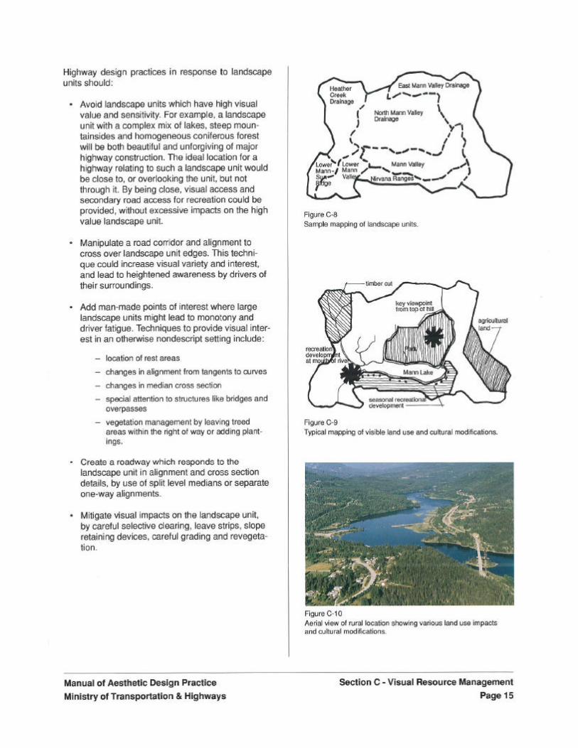
Design practices in response to landmarks should:
- Avoid highway alignments which obscure or come so close to attractor landmarks as to hinder their use and enjoyment. Avoid highway alignments which focus tangents or long curves on detractor landmarks.
* Manipulate highway alignments to focus tan- gents on attractor landmarks, for visual interest.
* Create landmarks in areas otherwise visually nondescript. Major highway structures such as bridges, overpasses, rest areas, etc. could all be attractor landmarks with careful design.
- Mitigate negative impacts on existing landmarks, by attention to detail highway align- ment, vegetation or earthform buffers, or relocationlcompensation for the landmark.
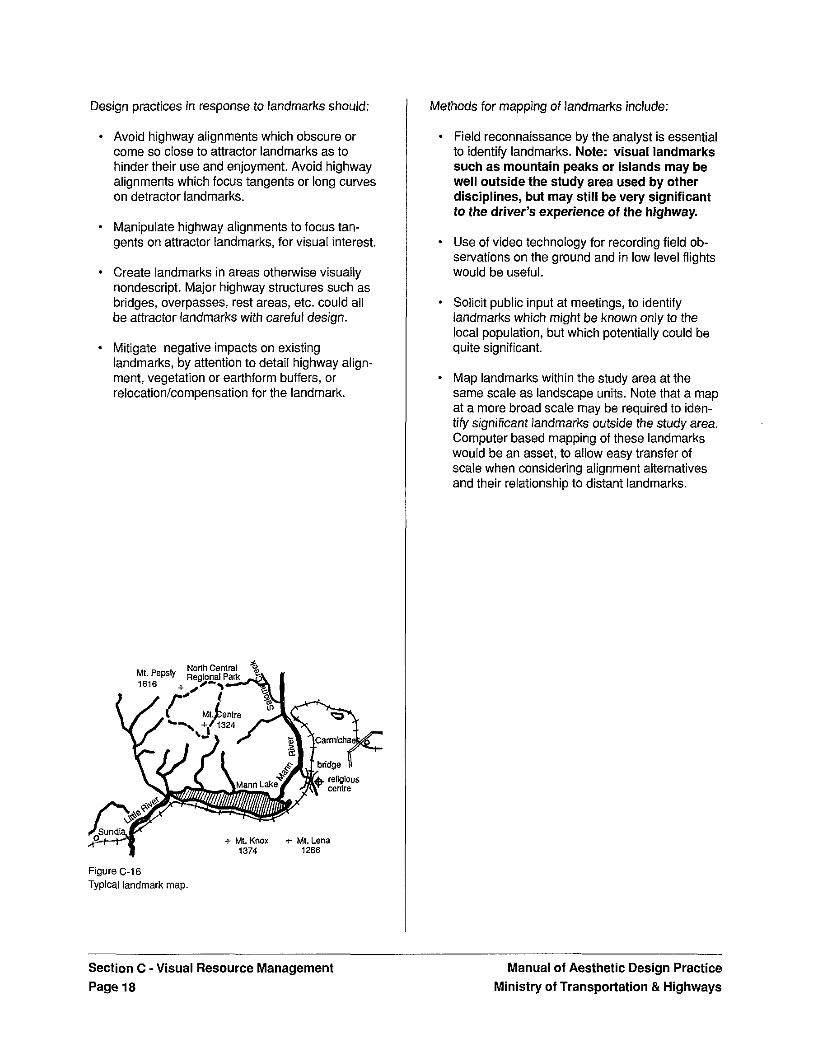
Figure C-16 Typical landmark map.
Methods for mapping of landmarks include:
- Field reconnaissance by the analyst is essential to identify landmarks. Note: visual landmarks such as mountain peaks or islands may be well outside the study area used by other disciplines, but may still be very significant to the driver's experience of the highway.
* Use of video technology for recording field ob- servations on the ground and in low level flights would be useful.
* Solicit public input at meetings, to identify landmarks which might be known only to the local population, but which potentially could be quite significant.
- Map landmarks within the study area at the same scale as landscape units. Note that a map at a more broad scale may be required to iden- tify significant landmarks outside the study area. Computer based mapping of these landmarks would be an asset, to allow easy transfer of scale when considering alignment alternatives and their relationship to distant landmarks.
Section C - Visual Resource Management Page 18
Manual of Aesthetic Design Practice Ministry of Transportation & Highways
5.0 Visual Quality Assessment
Assessment of relative visual quality of landscape units will be performed during corridor and/or alignment selection.
Visual Quality is the overall impression retained after driving through, walking through or flying over an area of land.
Some landscape units possess a higher visual quality than others. With the visual quality of landscape units categorized and mapped as high, medium or low, highway engineers and consultants can assess the visual impacts of highway developments by compar- ing the relative visual quality within different landscape units through which proposed alignments pass.
Note that each individual region in the Province should be acknowledged to have unique scenic attributes. Consequently, for highway design purposes, it is the relative quality among landscape units within a region or watershed which is a primary concern.
Design practices in response to visual quality assess- ment should:
* Avoid areas of high visual quality.
- Routing highways through areas of medium visual quality may provide an aesthetic ex- perience with acceptable impacts. At the same time, secondary road access to areas of high visual quality will provide recreation ac- cess.
- Create visual interest in areas of low visual quality to enrich the driver's experience.
- Provide scenic pullouts, viewpoints, rest areas and access to recreational oppor- tunities. Major structures such as bridges and overpasses could be attractor landmarks when carefully designed.
* Screen or avoid unsightly areas
- Mitigate impacts of highway development on high visual quality areas.
- Reduce visual impacts in these areas by care- ful detailed alignment, retaining devices, and detailed vegetation management.
Methods for assessing visual quality include:
* Review the landscape units and subunits mapped earlier.
* Application of a reasoned and supportable rating system. This should be done by a profes- sional Landscape Architect, or related discipline, with expertise in landscape aes- thetics. A sample of a numerical rating system is illustrated in Table C-1. This numerical system is a format for a complex value judgement. As- sessing the relative visual quality of different landscapes is by nature subjective. Designers should make an initial ranking of high, medium and low visual quality, then confirm and refine this judgement by comparison with the assess- ments of public representatives. The best visual quality ranking will be developed from consult- ations with people from different backgrounds.
* Summarize visual quality ratings on a map at the same scale as the landscape unit mapping.
- Record the process and reasoning which led to the visual quality ratings.
Manual of Aesthetic Design Practice Ministry of Transportation & Highways
Section C - Visual Resource Management Page 21
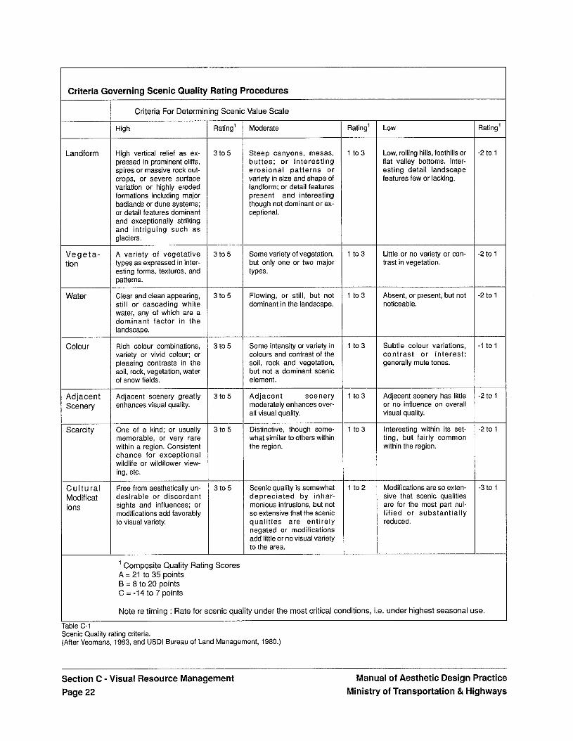
Criteria Governing Scenic Quality Rating Procedures
Criteria For Determining Scenic Value Scale ~
Rating’ Moderate Rating’ LOW Rating’ ~
.andfor1
High
High vedical relief as ex- pressed in prominent cliffs, spires or massive rock out- crops, or severe suriace variation or highly eroded formations including major badlands or dune systems; or detail features dominant and exceptionally striking and intriguing such as glaciers.
A variety of vegetative types as expressed in inter- esting forms, textures, and patterns.
Clear and clean appearing, still or cascading white water, any of which are a dominant factor in the landscape.
Rich colour combinations, variety or vivid colour; or pleasing contrasts in the soil. rock, vegetation, water of snow fields.
Adjacent scenery greatly enhances visual quality.
3 to 5
~
3 t 0 5
1 to 3 Low, rolling hills. foothills or flat valley bottoms. Inter- esting detail landscape features few or lacking.
-2 to 1 Steep canyons. mesas, buttes; or interest ing erosional pat terns or variety in size and shape of landform; or detail features present and interesting though not dominant or ex- ceptional.
1 to 3 Little or no variety or con- trast in vegetation.
-2 to 1 / e g e t : ion
Some variety of vegetation, but only one or two major types.
Vater 3 to 5
___ 3 to 5
Flowing, or still, but not dominant in the landscape.
1 to3
~
1 t 03
Absent, or present, but not noticeable.
-2 to 1
Some intensity or variety in colours and contrast of the soil, rock and vegetation, but not a dominant scenic element.
Subtle colour variations, contrast or interest ; generally mute tones.
-1 to 1 :olour
i d jace i Scenery
Scarcity ~
~
: u l tur , dodific; ons
3 to 5
~
3 to 5
Adjacent scenery moderately enhances over- ail visual quality.
Distinctive, though some- what similar to others within the region.
1 to 3
~
1 t o3
Adjacent scenery has little or no influence on overall visual quality.
Interesting within its set- ting, but fairly common within the region.
-2 to 1
~
-2 to 1 One of a kind; or usually memorable, or very rare within a region. Consistent chance for exceptional wildlife or wildilower view- ing, etc.
Free from aesthetically un- desirable or discordant sights and influences; or modifications add favorably to visual variety.
3 to 5 Scenic quality is somewhat depreciated by inhar- monious intrusions, but not so extensive that the scenic qual i t ies are entirely negated or modifications add little or no visual variety to the area.
1 to2 Modifications are so exten- sive that scenic qualities are for the most part nul- l i f ied or substantially reduced.
-3 to 1
Composite Quality Rating Scores A = 21 to 35 points B = 8 to 20 points C = -14 to 7 points
Note re timing : Rate for scenic quality under the most critical conditions, i.e. under highest seasonal use
ble C-1 :enic Quality rating criteria. fter Yeomans, 1983, and USDl Bureau of Land Management, 1980.)
Section C - Visual Resource Management Page 22
Manual of Aesthetic Design Practice Ministry of Transportation & Highways
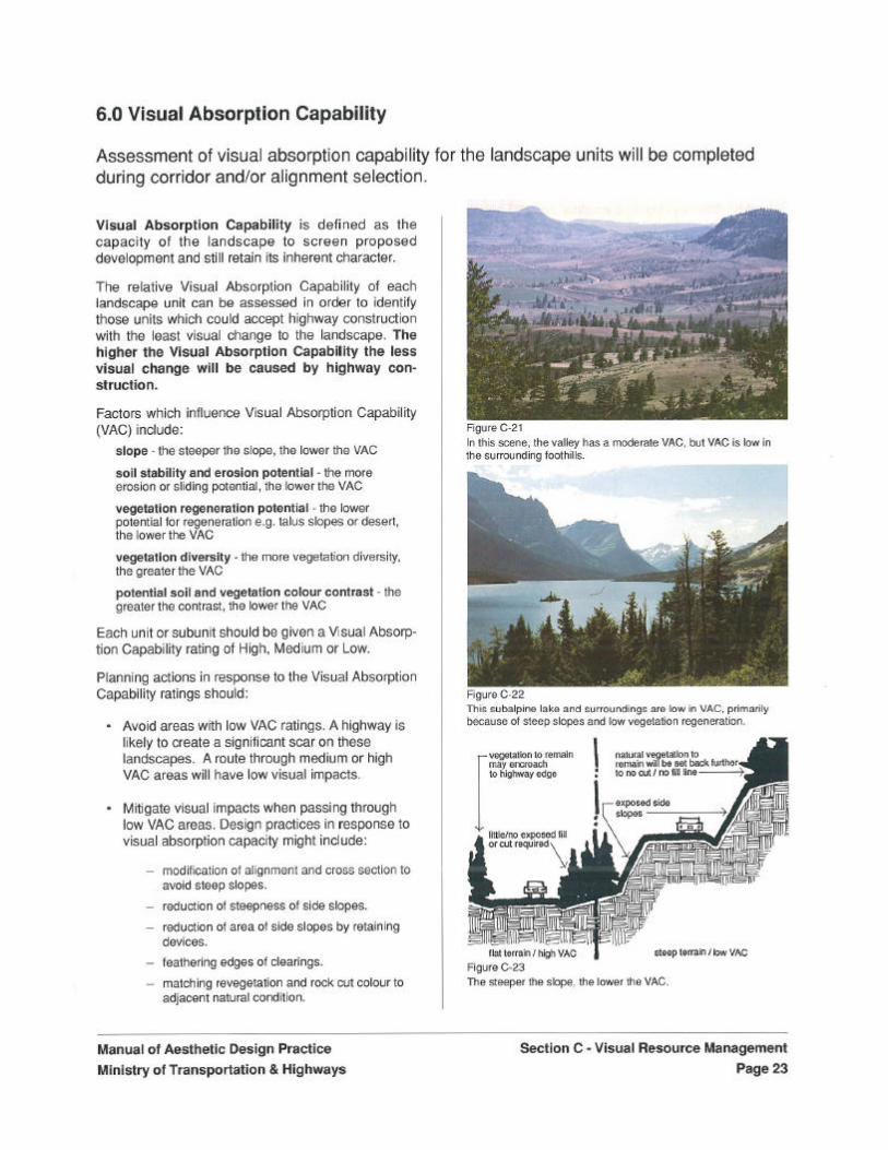
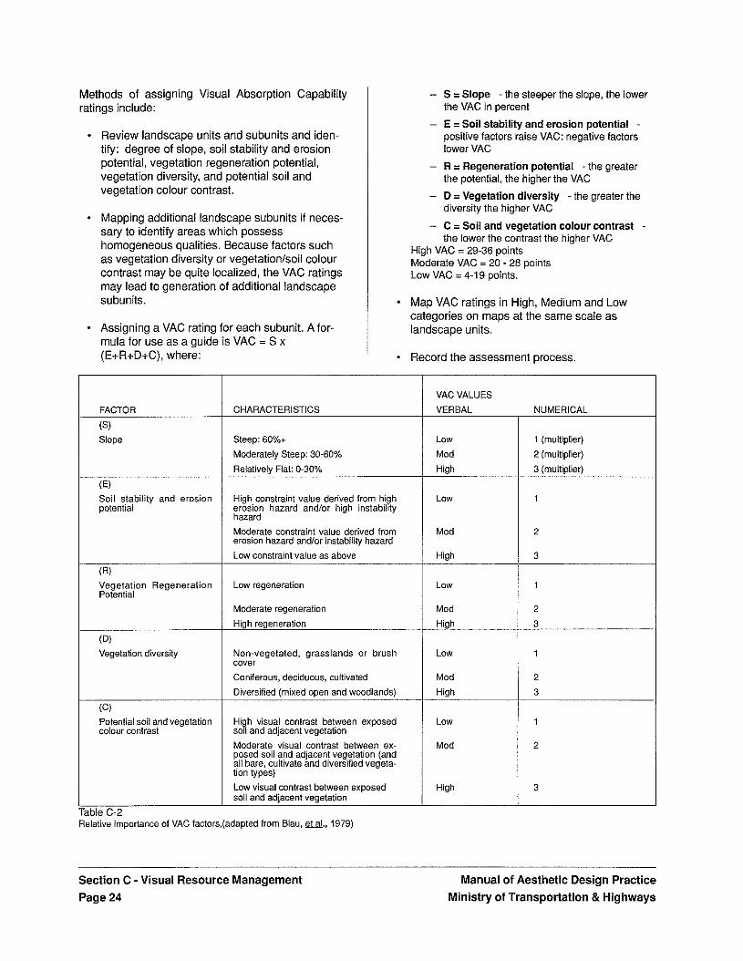
Methods of assigning Visual Absorption Capability ratings include:
- Review landscape units and subunits and iden- tify: degree of slope, soil stability and erosion potential, vegetation regeneration potential, vegetation diversity, and potential soil and vegetation colour contrast.
- Mapping additional landscape subunits if neces- sary to identify areas which possess homogeneous qualities. Because factors such as vegetation diversity or vegetationlsoil colour contrast may be quite localized, the VAC ratings may lead to generation of additional landscape subunits.
- Assigning a VAC rating for each subunit. Afor- mula for use as a guide is VAC = S x (E+R+D+C), where:
Slope
Vegetation Regeneration Potential
Vegetation diversity ILL
- S = Slope -the steeper the slope, the lower the VAC in percent
- E = Soil stability and erosion potential - positive factors raise VAC: negative factors lower VAC
- R = Regeneration potential -the greater the potential, the higher the VAC
- D 3: Vegetation diversity -the greater the diversity the higher VAC
- C = Soil and vegetation colour contrast - the lower the contrast the higher VAC
High VAC = 29-36 points Moderate VAC = 20 - 28 points Low VAC = 4-19 points.
* Map VAC ratings in High, Medium and Low categories on maps at the same scale as landscape units.
I * Record the assessment process.
CHARACTERISTICS
Steep: 60%+ Moderately Steep: 30-60% Relativelv Fiat: 0.30%
High constraint value derived from high erosion hazard and/or high instability hazard Moderate constraint value derived from erosion hazard and/or instability hazard Low constraint value as above
Low regeneration
Moderate regeneration High regeneration
Non-vegetated, grasslands or brush cover Coniferous, deciduous, cultivated Diversified (mixed open and woodlands)
High visual contrast between exposed soil and adjacent vegetation Moderate visual contrast between ex- posed soil and adjacent vegetation (and all hare. cultivate and diversified vegeta- tion types)
Table C-2 Relative importance of VAC factors,(adapted from Blau. U., 1979)
Low visuai contrast between exposed soil and adjacent vegetation
VAC VALUES VERBAL
LOW Mod High
LOW
Mod
Hioh
LOW
Mod High
Low
Mod High
LOW
Mod
High
NUMERICAL
1 (multiplier) 2 (multiplier) 3 (multiplier)
1
2
3
1
2
3
Section C - Visual Resource Management Page 24
Manual of Aesthetic Design Practice Ministry of Transportation & Highways
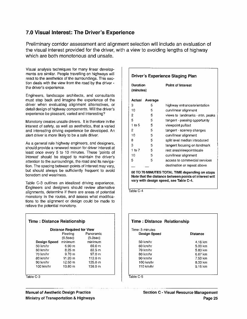
7.0 Visual Interest: The Driver's Experience
Preliminary corridor assessment and alignment selection will include an evaluation of the visual interest provided for the driver, with a view to avoiding lengths of highway which are both monotonous and unsafe.
Visual analysis techniques for many linear develop- ments are similar. People travelling on highways will react to the aesthetics of the surroundings. This sec- tion deals with the view from the road by the driver - the driver's experience.
Engineers, landscape architects, and consultants must step back and imagine the experience of the driver when evaluating alignment alternatives, or detail design of highway components. Will the driver's experience be pleasant, varied and interesting?
Monotony creates unsafe drivers. It is therefore in the interest of safety, as well as aesthetics, that a varied and interesting driving experience be developed. An alert driver is more likely to be a safe driver.
As a general rule highway engineers, and designers, should provide a renewed reason for driver interest at least once every 5 to 10 minutes. These 'points of interest' should be staged to maintain the driver's attention to the surroundings, the road and its naviga- tion. The spacing between points of interest may vary, but should always be sufficiently frequent to avoid boredom and weariness.
Table C-3 outlines an idealized driving experience. Engineers and designers should review alternative alignments, determine if there are areas of potential monotony in the routes, and assess what modifica- tions to the alignment or design could be made to relieve the potential monotony.
Time : Distance Relationship
Distance Required for View Fleeting Panoramic (0.5sec) (5.0sec)
Design Speed minimum minim u m 50 kmlhr 6.90 m 69.0 m 60 kmlhr 8.25 m 82.5 m 70 kmlhr 9.70 m 97.0 m 80 kmlhr 11.20 m 112.0 m 90 kmlhr 12.50 m 125.0 m 100 kmlhr 13.80 m 138.0 m
iable C-3
Manual of Aesthetic Design Practice -
Ministry of Transportation & Highways
Driver's Experience Staging Plan
Duration (minutes)
Actual Average 3 5 10 5 2 5 5 5 1 to 5 5 2 5 10 5 8 5 3 5 1 to7 5 10 5 5 5 - -
Point of Interest
highway entrancelorientation curvilinear alignment views to landmarks - mtn. peaks tangent - passing opportunity viewpoint pullout tangent -scenery changes curvilinear alignment split level median introduced tangent focusing on landmark rest areaiviewpointfscale curvilinear alignment access to commercial services destination or repeat above
60 TO 70 MINUTES TOTAL TIME depending on stops Note that the distance between points of interest will vary with design speed, see Table C-4.
rble C-4
Time : Distance Relationship
Time: 5 minutes Design Speed
50 kmlhr 60 kmlhr 70 kmlhr 80 kmlhr 90 kmlhr 100 kmlhr 110 kmlhr
Distance
4.16 km 5.00 km 5.83 km 6.67 km 7.50 km 8.33 km 9.16 km
Section C - Visual Resource Management Page 25
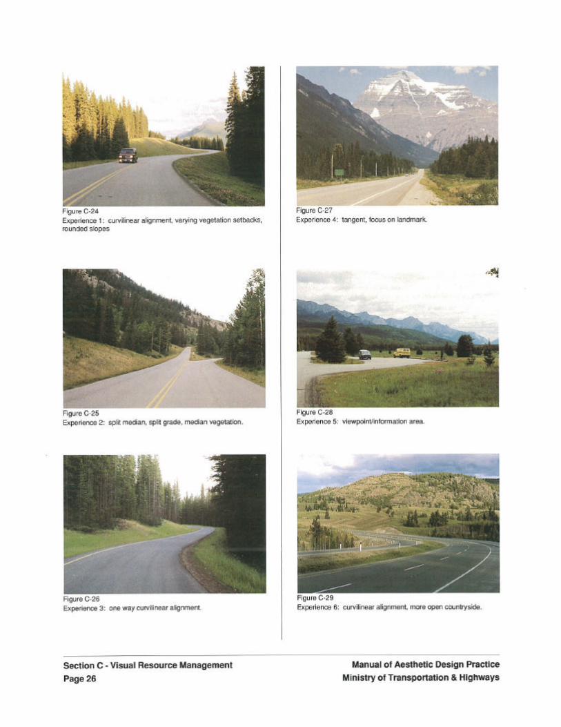
Methods of stimulating driver interest could include:
Varying the alignment style of the road between tangential and curvilinear alignments.
- Changing the cross section of the road, by ad- ding a median, or by creating a split level section.
- Accessing views from the road. These may be appreciated while driving the road, or may be ac- cessed by pullouts or rest areas. This requires careful alignment decisions, and selective vegetation removal.
- Focusing tangents on natural and created landmarks.
- Providing interpretive signage and related rest areas.
- Providing direct access to roadside trails, bikeways, parks, and picnic areas
- Providing roadside rest areas and tourist infor- mation centres.
- Providing access to commercial facilities - vil- lages, service stations, tourist attractions and accommodations.
- Careful design of bridges, tunnels and overpas- ses, and means to stop to appreciate these structures.
* Aligning the road to move into a different landscape unit, thereby creating a change in scenery.
Manipulating roadside vegetation and planting to create interest - leaving stands of trees in the median, feathering the edges of clearings, or in- stalling accent plantings
* Accent lighting for bridges, tunnel portals, road- side waterfalls.
Methods for Assessing Visual Interest include:
- Review of potential corridor or alignment alter- natives.
Identification of points of interest along each al- ternative.
- Measuring the distance and determining the time interval at the design speed between such points.
- Identification of sections where the time interval will exceed 5 minutes.
* Assess what refinements or additions could be made to reduce the time interval in those sec- tions.
- Suggestion of other alignment changes or addi- tions which could improve the driver's experience.
* Ranking which alternatives are best in terms of driver's experience.
- Documenting recommendations and mapping points of interest at same scale as alignment alternatives.
Manual of Aesthetic Design Practice Ministry of Transportation & Highways
Section C -Visual Resource Management Page 27
8.0 Integration of Guidelines into Highway Design
Visual Resource Management considerations will be integrated into the highway design process in parallel with other considerations, from the time of project identification through to completion of construction.
Visual resource management is only one factor among many to be addressed in highway design. Successful design must balance factors such as high- way function, economics, political and cultural jurisdictions, fisheries and wildlife, forestry, and recreation as well as aesthetics. Aesthetic considera- tions cannot be adequately addressed after a highway is designed, but must be incorporated throughout the design process.
Visual Opportunities and Constraints
To allow fair value judgments to be made, it is neces- sary for visual factors to be presented in a map form which is parallel with that of other factors. It is also necessary to identify at what points in the design process visual factors are best considered.
To allow integration with other disciplines, critical visual factors should be summarized in a Visual Op- portunities and Constraints Map. This map should highlight those visual factors which would be of most significance to highway designers. These factors might include:
areas of high visual quality and low visual absorption capability.
. dramatic edges of landscape units,
- attractor landmarks, and potential tangents which would focus on them.
. attractor landmarks which will accommodate
. detractor landmarks, and extent of visual influence
. significant existing viewsheds, and potential
. significant vegetation changes or clearings, eithei
In general, the opportunities and constraints map should summarize those elements which the visual resource analysts suggest are important to the align- ment and design of the highway. In complex cases, for purposes of clarity, it may be necessary to create a separate map for constraints, and a separate map for opportunities.
These maps should be to the same scale as the maps
recreational use and their access points.
viewpoints.
natural or rnanrnade.
Section C - Visual Resource Management
being used for highway planning purposes. The op- portunities and constraints maps should be supported by explanatory text, cross referenced to the supporting detailed maps and documents created in previous visual resource management steps outlined herein.
Visual Impact Simulation
Issues may arise during the course of design which would benefit from simulation of visual impacts or opportunities. Computer programs exist to create im- ages which represent fairly the appearance of an alternative. Programs are able to plot a seen area and create a perspective image of major earthworks or clearing activities.
Combining video cameras and software allows a video image to be digitized, and then to have a second video or drawn image superimposed. This creates video images of proposed changes, and is very useful for visualizing the impact or benefits of alternatives from specific viewpoints.
Simulation as described above should be used when resolution of a specific issue is sought.
Manual of Aesthetic Design Practice Page 28 Ministry of Transportation & Highways
Aesthetic Design Process
Aesthetic factors should be incorporated into high- way design from the inception of a project to its con- struction completion. The following provides a checklist for incorporating aesthetic considerations into a typical highway design process.
At Project Identification and prior to corridor selection
- Review the general scenic quality of the landscape to be traversed.
Assess the type of users who will predominate on the highway - tourist, recreational, commer- cial, or commuter.
- Assess the destinations along the highway- urban, suburban, rural, resort area, through traf- fic.
- Determine the Aesthetic classification of the highway or portion of the highway:
- Baseline Highway - Tourway - Parkwav
During Corridor Assessment:
- Perform a visual resource inventory, including:
- landscape units and subunits. - landmarks. - views and viewsheds.
* Complete visual resource assessments, including:
- visual quality assessment. - visual absorption capability assessment.
- Summarize visual opportunities and constraints.
- Incorporate visual factors in corridor alternatives.
* Review the visual impacts of corridor alterna tives, and recommend a preferred corridor.
- Assess selected corridor, and suggest means to improve corridor boundary.
- Identify mitigating measures necessary.
- Record anticipated visual impacts of the selected corridor, and in particular ensure that directives for future planning and mitigating measures are documented and highlighted to planners at more detailed scales.
Manual of Aesthetic Design Practice Section C - Visual Resource Management Ministry of Transportation & Highways Page 29
During Alignment Selection:
- Review, update and complete visual resource data base from corridor assessment. If no such data base was generated, develop one.
* Transfer visual resource data to the alignment planning scale.
Summarize visual opportunities and constraints relevant to alignment selection.
* Incorporate visual factors in identification of alignment alternatives.
- Review the visual impacts of alignment alterna- tives, and recommend a preferred alignment.
- Assess selected alignment, and suggest means to improve alignment in particular concerning visual interest and driver's experience. Locate and perform preliminary design for rest areas, pullouts, and other roadside facilities.
* Identify mitigating measures necessary. Provide cost estimate of required mitigating measures, and ensure that associated budgets are allo- cated.
- Record anticipated visual impacts of the selected alignment, and in particular ensure that dii-ectives for' future design and mitigating measures are documented and highlighted to planners and designers at detailed scales.
During Detail Design:
- Provide direction on detail design and im. plementation of mitigating measures.
* Monitor detail design of alignment, cross sec- tion and typical details. Consider refinements which accommodate recommended guidelines.
* Provide leadership in aesthetics of: detail design of roadside facilities, roadside clearing and grubbing, earthworks, structures, revegetation, and roadside facilities.
* Produce cost estimates of roadside develop- ment and mitigating measures. Ensure appropriate budgets are allocated, and com- plete working drawings and specifications.
Ensure that aesthetic mitigating measures re. quired as a result of one discipline's design solutions are addressed in working drawings and specifications of other appropriate dis- ciplines.
During Construction:
- Provide field review services during clearing and grubbing, to ensure that required buffer areas remain and are protected, and that vegetation management as prescribed is per- formed.
- Identify minor modifications to site grading for slope rounding, rock outcrop treatment, or tree belts.
- Supervise finished grading and revegetation in the field.
After Construction:
Develop maintenance procedures which sup- port and develop the aesthetic intents developed in the previous stages.
- Provide the required resources to adequately maintain this visual resource.
Note: Document project successes and failures for the future information of other Ministry personnel and con- sultants.
Section C -Visual Resource Management Page 30
Manual of Aesthetic Design Practice Ministry of Transportation & Highways