Embed Size (px)
Citation preview
©Copyright Task Force Tips, Inc. 2010-2017 LIA-420 September 5, 2017 Rev07
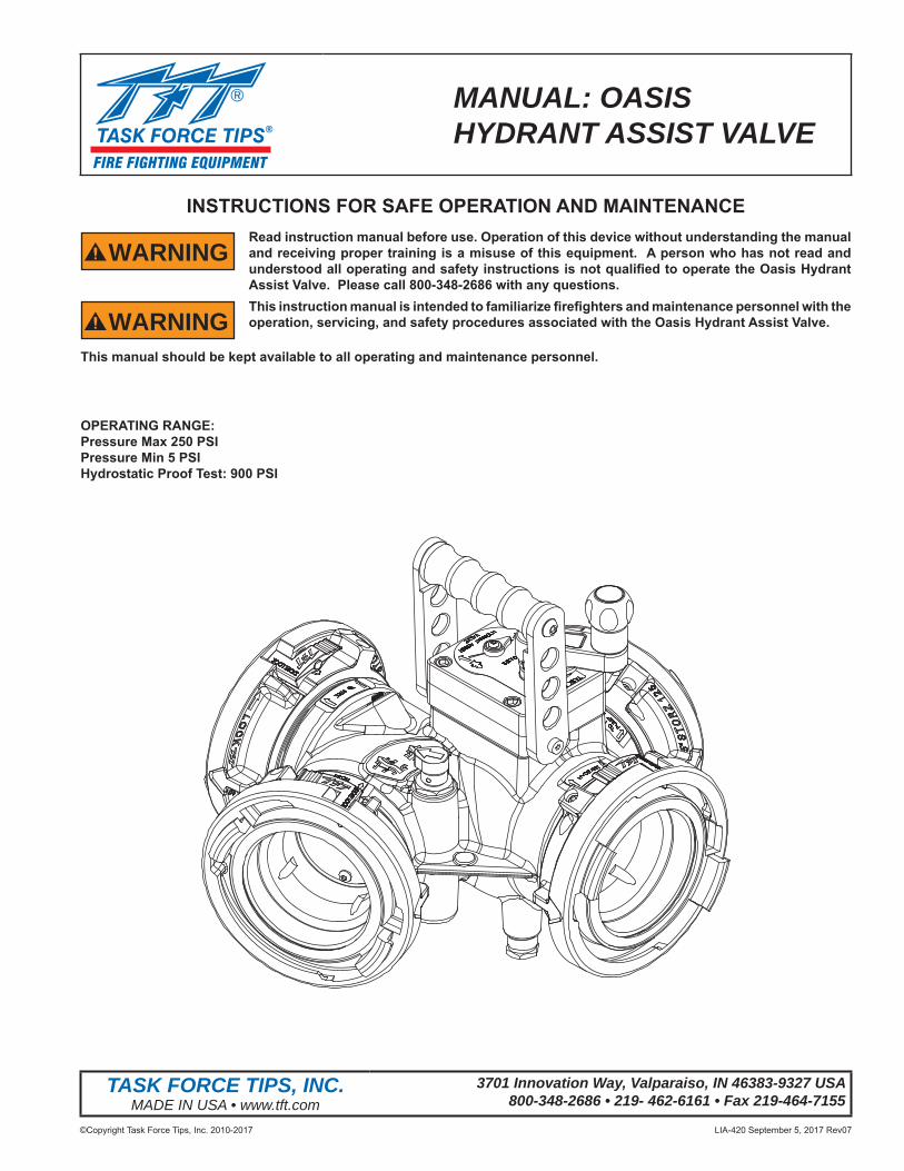
MANUAL: OASIS HYDRANT ASSIST VALVE
INSTRUCTIONS FOR SAFE OPERATION AND MAINTENANCE
WARNINGRead instruction manual before use. Operation of this device without understanding the manual and receiving proper training is a misuse of this equipment. A person who has not read and understood all operating and safety instructions is not qualifi ed to operate the Oasis Hydrant Assist Valve. Please call 800-348-2686 with any questions.
WARNINGThis instruction manual is intended to familiarize fi refi ghters and maintenance personnel with the operation, servicing, and safety procedures associated with the Oasis Hydrant Assist Valve.
This manual should be kept available to all operating and maintenance personnel.
OPERATING RANGE:Pressure Max 250 PSIPressure Min 5 PSIHydrostatic Proof Test: 900 PSI
TASK FORCE TIPS, INC.MADE IN USA • www.tft.com
3701 Innovation Way, Valparaiso, IN 46383-9327 USA800-348-2686 • 219- 462-6161 • Fax 219-464-7155
©Copyright Task Force Tips, Inc. 2010-2017 LIA-420 September 5, 2017 Rev072
DANGERPERSONAL RESPONSIBILITY CODE
The member companies of FEMSA that provide emergency response equipment and services want responders to know and understand the following:1. Firefi ghting and Emergency Response are inherently dangerous activities
requiring proper training in their hazards and the use of extreme caution at all times.
2. It is your responsibility to read and understand any user’s instructions, including purpose and limitations, provided with any piece of equipment you may be called upon to use.
3. It is your responsibility to know that you have been properly trained in Firefi ghting and /or Emergency Response and in the use, precautions, and care of any equipment you may be called upon to use.
4. It is your responsibility to be in proper physical condition and to maintain the personal skill level required to operate any equipment you may be called upon to use.
5. It is your responsibility to know that your equipment is in operable condition and has been maintained in accordance with the manufacturer’s instructions.
6. Failure to follow these guidelines may result in death, burns or other severe injury.
FEMSA Fire and Emergency Manufacturers and Service AssociationP.O. Box 147, Lynnfi eld, MA 01940 • www.FEMSA.org
©Copyright Task Force Tips, Inc. 2010-2017 LIA-420 September 5, 2017 Rev073
Table Of Contents 1.0 MEANING OF SAFETY SIGNAL WORDS ....................................................................... 4 2.0 SAFETY ............................................................................................................................ 4 3.0 GENERAL INFORMATION ............................................................................................... 5 3.1 PARTS IDENTIFICATION 3.2 SPECIFICATIONS 3.3 CORROSION 3.4 USE WITH SALT WATER: 4.0 INSTALLATION ................................................................................................................. 6 4.1 CHANGING OFFSET OF CRANK HANDLE 5.0 USE ............................................................................................................................. 7-11 5.1 ATTACH TO A HYDRANT 5.2 HYDRANT ASSIST OPERATION 5.3 RELAY OPERATION 5.4 CLAPPER VALVE POSITION INDICATOR 5.5 FLOW INCREASE FROM BOOSTING 5.6 VALVE PRESSURE LOSS 6.0 MODIFICATION PROCEDURE TO ALLOW SHUT-OFF OF THE HYDRANT ............... 12 7.0 EXPLODED VIEWS & PARTS LISTS .......................................................................13-17 7.1 OASIS HYDRANT ASSIST VALVE 7.2 INLET/OUTLET OPTIONS 7.3 CLAPPER 7.4 PARALLEL DRIVE GEARBOX 8.0 WARRANTY ................................................................................................................... 18 9.0 MAINTENANCE.............................................................................................................. 18 9.1 SERVICE TESTING ................................................................................................. 19 9.1.1 HYDRAULIC TESTING ................................................................................... 19 9.1.2 CHECK VALVE TESTING ............................................................................... 19 9.1.3 RECORDS ...................................................................................................... 19 9.2 REPAIR .................................................................................................................... 1910.0 ANSWERS TO YOUR QUESTIONS .............................................................................. 1910.0 OPERATION AND INSPECTION CHECKLIST .............................................................. 20

©Copyright Task Force Tips, Inc. 2010-2017 LIA-420 September 5, 2017 Rev074
1.0 MEANING OF SAFETY SIGNAL WORDSA safety related message is identifi ed by a safety alert symbol and a signal word to indicate the level of risk involved with a particular hazard. Per ANSI standard Z535.6-2006, the defi nitions of the four signal words are as follows:
DANGERDANGER indicates a hazardous situation which, if not avoided, will result in death or serious injury.
WARNINGWARNING indicates a hazardous situation which, if not avoided, could result in death or serious injury.
CAUTIONCAUTION indicates a potentially hazardous situation which, if not avoided, may result in minor or moderate injury.
NOTICENOTICE is used to address practices not related to personal injury.
2.0 SAFETY
WARNINGQuick changes in valve position can cause high pressure spikes due to water hammer and may result in damaged equipment which could lead to injury or death. Open and close the valve slowly to avoid water hammer.
WARNINGInjury or death may occur by attempting to use a damaged valve. Per NPFA 1962, the device shall be inspected and tested at least quarterly.Before use, inspect for damage resulting from: • Failure to drain valve followed by exposure to freezing conditions • Exposure to temperatures in excess of 160 degrees F • Missing parts, physical abuse
WARNINGThis equipment is intended for use by trained personnel for fi refi ghting. Its use for other purposes may involve hazards not addressed by this manual. Seek appropriate guidance and training to reduce risk of injury.
WARNINGKinks in supply hose may reduce water fl ow and cause injury or death to persons dependant on water fl ow. Avoid tight bends to minimize risk of hoseline kinks.
WARNINGThe valve may be damaged if frozen while containing signifi cant amounts of water. Such damage may be diffi cult to detect visually and can lead to possible injury or death. Any time the valve is subject to possible damage due to freezing, it must be hydrostatically tested by qualifi ed personnel before being considered safe for use.
CAUTIONMaximum operating pressure 250 psi (17 bar). Do not exceed 250 psi (17 bar) on either side of the valve.
CAUTIONValve must be properly connected. Mismatched or damaged connectors may cause leaking or uncoupling under pressure and could cause injury.
CAUTIONUse with salt water is permissible provided the valve is thoroughly cleaned with fresh water after each use. The service life of the valve may be shortened due to the eff ects of corrosion and is not covered under warranty.
©Copyright Task Force Tips, Inc. 2010-2017 LIA-420 September 5, 2017 Rev075
3.0 GENERAL INFORMATIONTFT’s Oasis Hydrant Assist Valve is a versatile valve that can be used as a hydrant booster, a gated wye, or for inline pumping during relay operations. In hydrant boosting operation, the valve is fi rst connected to the hydrant and to the intake supply line on the fi rst pumper. Inlet and outlet supply lines on a boost pumper are then connected to the valve to draw water directly from the hydrant connection and increase pressure/fl ow to the fi rst pumper. Inline pumping is achieved in a similar manner. A clapper valve with position indicator provides uninterrupted water fl ow to the fi re when transitioning to boost mode, and in the event of boost pump failure. Two unique valve position indicators tell the operator if the ball and clapper valves are open, closed, or somewhere in between. Designed for use with 3.5”, 4”, 4.5” or 5” (89, 100, 115 or 125 mm) hose. Aluminum half ball valve provides corrosion protection. Maximum operating pressure is 250 psi (17 bar). Meets 900 psi (62 bar) hydrostatic strength test. The aluminum casting is hardcoat anodized inside and out, and TFT powder coat fi nished on the outside.
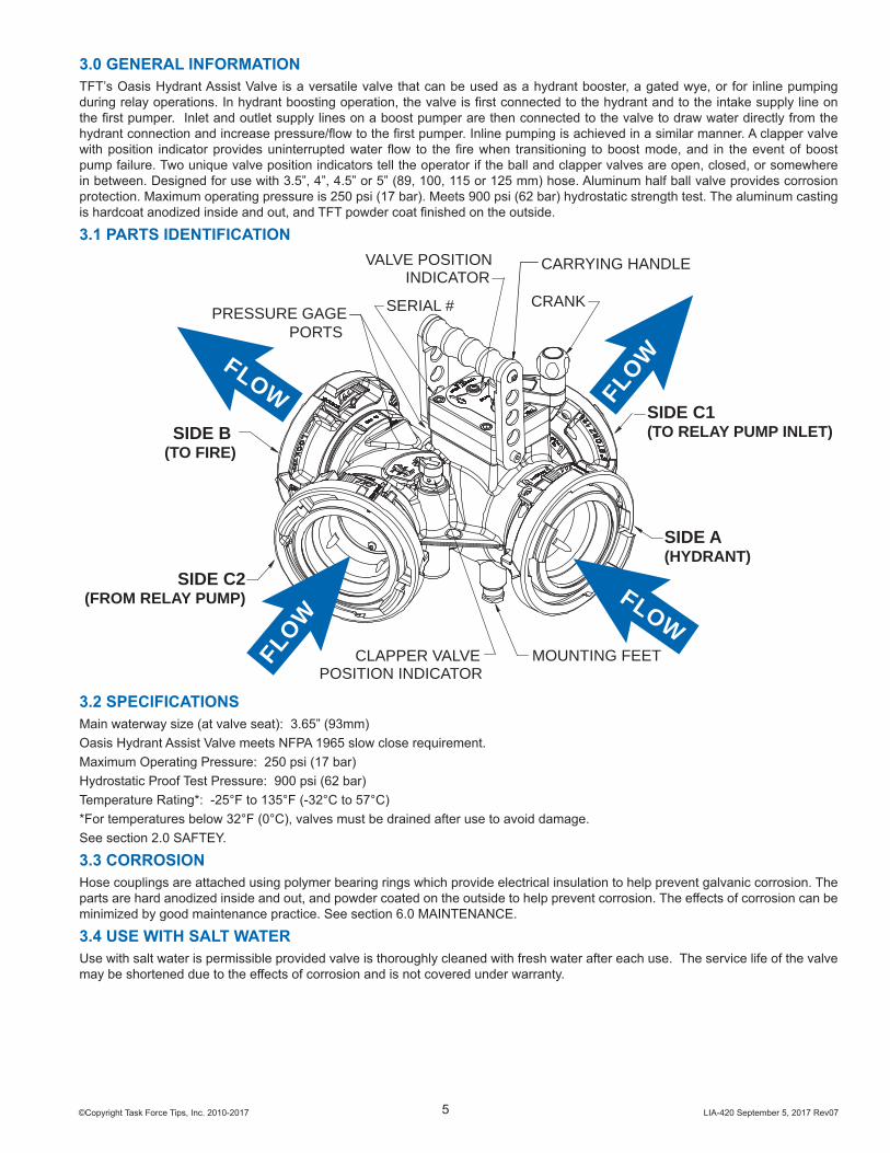
3.1 PARTS IDENTIFICATION
FLOW
FLOW
FLOW
FLOW
PRESSURE GAGEPORTS
SIDE C2(FROM RELAY PUMP)
CLAPPER VALVEPOSITION INDICATOR
SIDE B (TO FIRE)
MOUNTING FEET
SIDE A(HYDRANT)
SIDE C1(TO RELAY PUMP INLET)
CRANK
VALVE POSITIONINDICATOR
SERIAL #
CARRYING HANDLE
3.2 SPECIFICATIONSMain waterway size (at valve seat): 3.65” (93mm) Oasis Hydrant Assist Valve meets NFPA 1965 slow close requirement. Maximum Operating Pressure: 250 psi (17 bar)Hydrostatic Proof Test Pressure: 900 psi (62 bar)Temperature Rating*: -25°F to 135°F (-32°C to 57°C)*For temperatures below 32°F (0°C), valves must be drained after use to avoid damage. See section 2.0 SAFTEY.
3.3 CORROSIONHose couplings are attached using polymer bearing rings which provide electrical insulation to help prevent galvanic corrosion. The parts are hard anodized inside and out, and powder coated on the outside to help prevent corrosion. The eff ects of corrosion can be minimized by good maintenance practice. See section 6.0 MAINTENANCE.
3.4 USE WITH SALT WATERUse with salt water is permissible provided valve is thoroughly cleaned with fresh water after each use. The service life of the valve may be shortened due to the eff ects of corrosion and is not covered under warranty.
©Copyright Task Force Tips, Inc. 2010-2017 LIA-420 September 5, 2017 Rev076
4.0 INSTALLATIONMake connections to fi re hose or fi ttings on each side of the Oasis Hydrant Assist Valve
CAUTIONDissimilar metals coupled together can cause galvanic corrosion that can result in the inability to unscrew the threads and complete loss of thread engagement over time. Per NFPA 1962 (1998 edition), if dissimilar metals are left coupled together an anti-corrosive lubricant should be applied to the threads. Also, the coupling should be disconnected and inspected at least quarterly.
CAUTIONMale fi re hose threads are sharp and can cause injury. Be careful when around male hose threads.
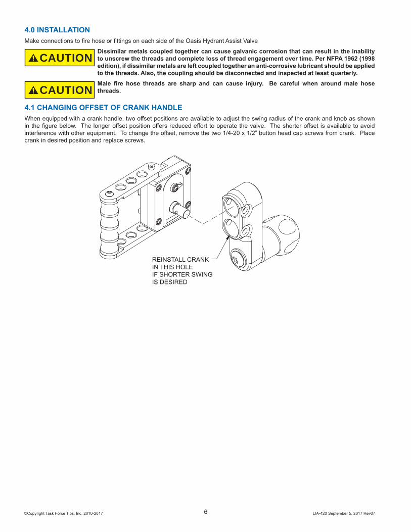
4.1 CHANGING OFFSET OF CRANK HANDLEWhen equipped with a crank handle, two off set positions are available to adjust the swing radius of the crank and knob as shown in the fi gure below. The longer off set position off ers reduced eff ort to operate the valve. The shorter off set is available to avoid interference with other equipment. To change the off set, remove the two 1/4-20 x 1/2” button head cap screws from crank. Place crank in desired position and replace screws.
REINSTALL CRANK IN THIS HOLEIF SHORTER SWING IS DESIRED
©Copyright Task Force Tips, Inc. 2010-2017 LIA-420 September 5, 2017 Rev077
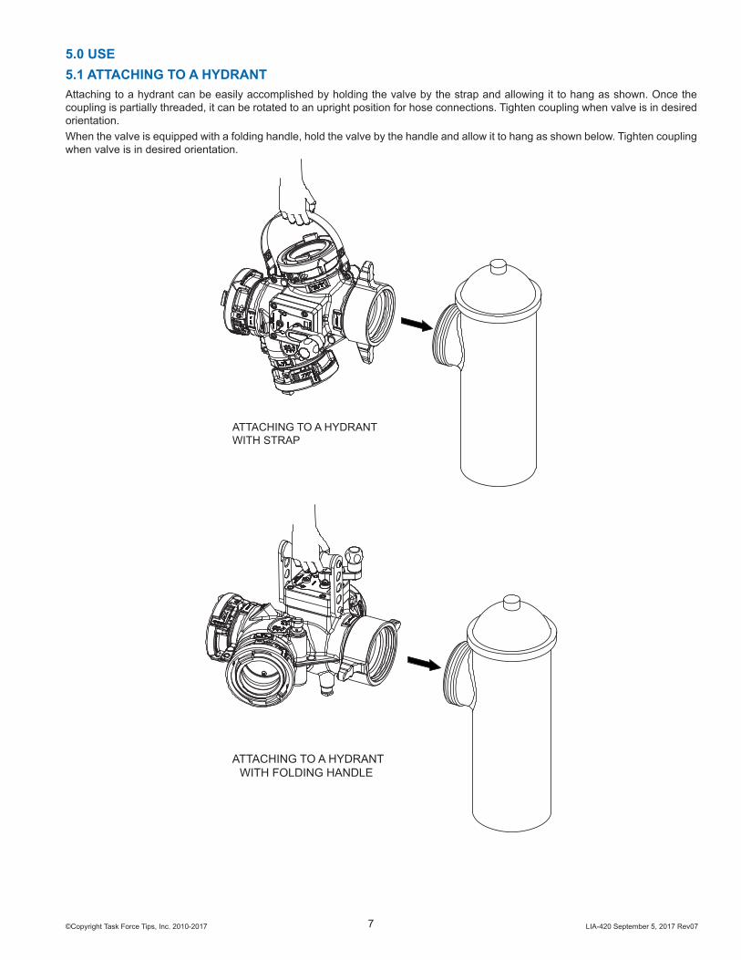
5.0 USE5.1 ATTACHING TO A HYDRANTAttaching to a hydrant can be easily accomplished by holding the valve by the strap and allowing it to hang as shown. Once the coupling is partially threaded, it can be rotated to an upright position for hose connections. Tighten coupling when valve is in desired orientation.When the valve is equipped with a folding handle, hold the valve by the handle and allow it to hang as shown below. Tighten coupling when valve is in desired orientation.
ATTACHING TO A HYDRANTWITH STRAP
ATTACHING TO A HYDRANTWITH FOLDING HANDLE
©Copyright Task Force Tips, Inc. 2010-2017 LIA-420 September 5, 2017 Rev078
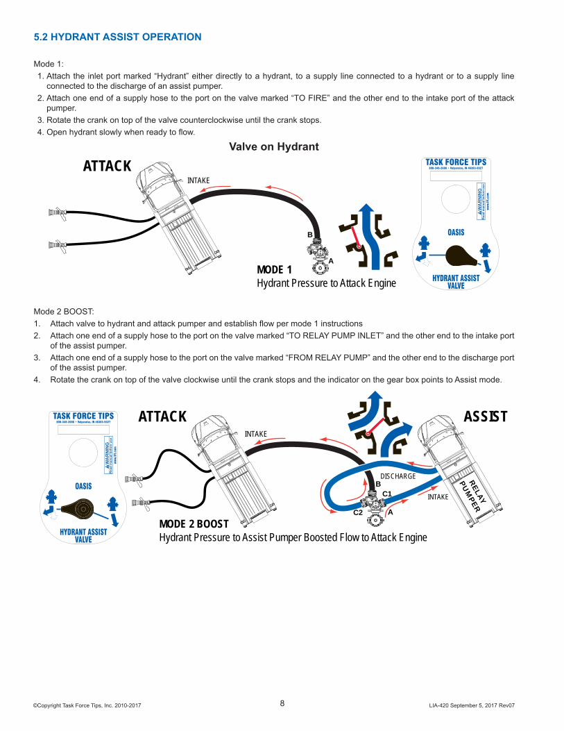
Mode 2 BOOST:1. Attach valve to hydrant and attack pumper and establish fl ow per mode 1 instructions2. Attach one end of a supply hose to the port on the valve marked “TO RELAY PUMP INLET” and the other end to the intake port
of the assist pumper.3. Attach one end of a supply hose to the port on the valve marked “FROM RELAY PUMP” and the other end to the discharge port
of the assist pumper.4. Rotate the crank on top of the valve clockwise until the crank stops and the indicator on the gear box points to Assist mode.
INTAKE
INTAKE
DISCHARGE
MODE 2 BOOSTHydrant Pressure to Assist Pumper Boosted Flow to Attack Engine
ATTACK ASSIST
A
BC1
C2
RELAY
PUM
PER
HYDRANT ASSIST
800-348-2686 • Valparaiso, IN 46383-9327TASK FORCE TIPS
Rea
d m
anua
l bef
ore
use.
WA
RN
ING
ww
w.tf
t.com
OASIS
VALVE
5.2 HYDRANT ASSIST OPERATION
Mode 1:1. Attach the inlet port marked “Hydrant” either directly to a hydrant, to a supply line connected to a hydrant or to a supply line
connected to the discharge of an assist pumper.2. Attach one end of a supply hose to the port on the valve marked “TO FIRE” and the other end to the intake port of the attack
pumper.3. Rotate the crank on top of the valve counterclockwise until the crank stops.4. Open hydrant slowly when ready to fl ow.
Valve on Hydrant
HYDRANT ASSIST
800-348-2686 • Valparaiso, IN 46383-9327TASK FORCE TIPS
Rea
d m
anua
l bef
ore
use.
WA
RN
ING
ww
w.tf
t.com
OASIS
VALVE
INTAKE
MODE 1Hydrant Pressure to Attack Engine
ATTACK
A
B

©Copyright Task Force Tips, Inc. 2010-2017 LIA-420 September 5, 2017 Rev079
5.3 RELAY OPERATION
MODE 1Valve In Street Ready For Relay OperationsSource Pressure to Attack Engine
To Attack Engine
A
B
From SupplySource
HYDRANT ASSIST
800-348-2686 • Valparaiso, IN 46383-9327TASK FORCE TIPS
Rea
d m
anua
l bef
ore
use.
WA
RN
ING
ww
w.tf
t.com
OASIS
VALVEINTAKE
DISCHARGE
MODE 2 BOOSTSource Pressure to Assist PumperBoosted Flow to Attack Engine
To Attack Engine
ASSIST
A
B
C1
C2
From SupplySource
HYDRANT ASSIST
800-348-2686 • Valparaiso, IN 46383-9327TASK FORCE TIPS
Rea
d m
anua
l bef
ore
use.
WA
RN
ING
ww
w.tf
t.com
OASIS
VALVE RELAY
PUMPER
©Copyright Task Force Tips, Inc. 2010-2017 LIA-420 September 5, 2017 Rev0710
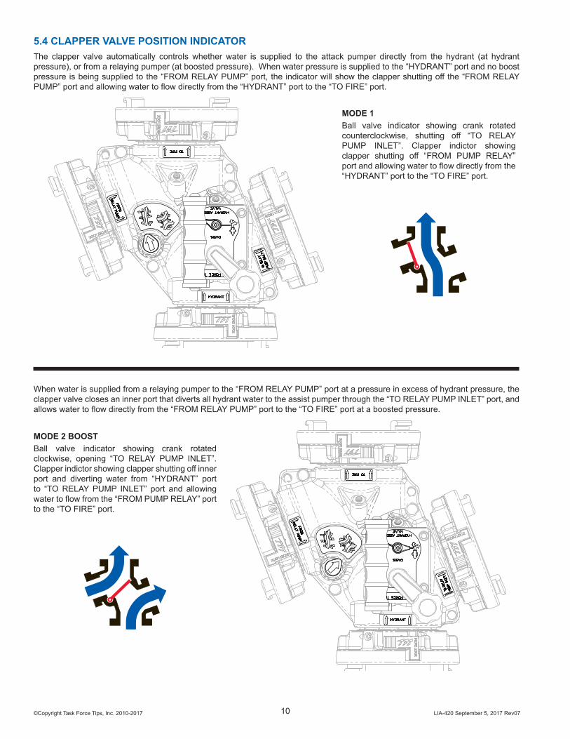
5.4 CLAPPER VALVE POSITION INDICATORThe clapper valve automatically controls whether water is supplied to the attack pumper directly from the hydrant (at hydrant pressure), or from a relaying pumper (at boosted pressure). When water pressure is supplied to the “HYDRANT” port and no boost pressure is being supplied to the “FROM RELAY PUMP” port, the indicator will show the clapper shutting off the “FROM RELAY PUMP” port and allowing water to fl ow directly from the “HYDRANT” port to the “TO FIRE” port.
MODE 1Ball valve indicator showing crank rotated counterclockwise, shutting off “TO RELAY PUMP INLET”. Clapper indictor showing clapper shutting off “FROM PUMP RELAY” port and allowing water to fl ow directly from the “HYDRANT” port to the “TO FIRE” port.
When water is supplied from a relaying pumper to the “FROM RELAY PUMP” port at a pressure in excess of hydrant pressure, the clapper valve closes an inner port that diverts all hydrant water to the assist pumper through the “TO RELAY PUMP INLET” port, and allows water to fl ow directly from the “FROM RELAY PUMP” port to the “TO FIRE” port at a boosted pressure.
MODE 2 BOOSTBall valve indicator showing crank rotated clockwise, opening “TO RELAY PUMP INLET”. Clapper indictor showing clapper shutting off inner port and diverting water from “HYDRANT” port to “TO RELAY PUMP INLET” port and allowing water to fl ow from the “FROM PUMP RELAY” port to the “TO FIRE” port.
©Copyright Task Force Tips, Inc. 2010-2017 LIA-420 September 5, 2017 Rev0711
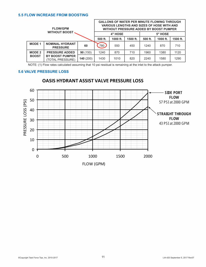
5.5 FLOW INCREASE FROM BOOSTING
FLOW/GPMWITHOUT BOOST
GALLONS OF WATER PER MINUTE FLOWING THROUGH VARIOUS LENGTHS AND SIZES OF HOSE WITH AND WITHOUT PRESSURE ADDED BY BOOST PUMPER
4" HOSE 5" HOSE500 ft. 1000 ft. 1500 ft. 500 ft. 1000 ft. 1500 ft.
MODE 1 NOMINAL HYDRANT PRESSURE 60 780 550 450 1240 870 710
MODE 2 BOOST
PRESSURE ADDED BY BOOST PUMPER (TOTAL PRESSURE)
90 (150) 1240 870 710 1960 1380 1120
140 (200) 1430 1010 820 2240 1580 1290
NOTE: (1) Flow rates calculated assuming that 10 psi residual is remaining at the inlet to the attack pumper.
5.6 VALVE PRESSURE LOSS
OASIS HYDRANT ASSIST VALVE PRESSURE LOSS
0
10
20
30
40
50
60
0 500 1000 1500 2000
FLOW (GPM)
PRES
SURE
LO
SS (P
SI)
SIDE PORT FLOW
57 PSI at 2000 GPM
STRAIGHT THROUGHFLOW
43 PSI at 2000 GPM
©Copyright Task Force Tips, Inc. 2010-2017 LIA-420 September 5, 2017 Rev0712
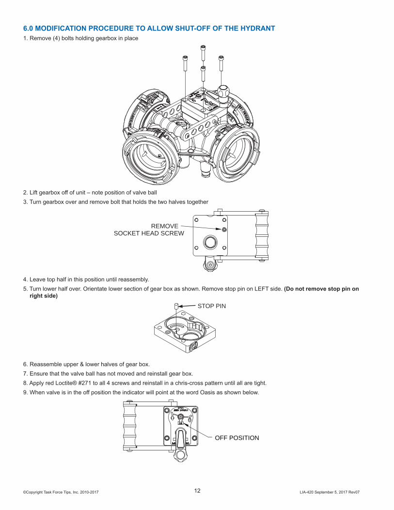
6.0 MODIFICATION PROCEDURE TO ALLOW SHUT-OFF OF THE HYDRANT1. Remove (4) bolts holding gearbox in place
2. Lift gearbox off of unit – note position of valve ball3. Turn gearbox over and remove bolt that holds the two halves together
REMOVESOCKET HEAD SCREW
4. Leave top half in this position until reassembly.5. Turn lower half over. Orientate lower section of gear box as shown. Remove stop pin on LEFT side. (Do not remove stop pin on
right side)
STOP PIN
6. Reassemble upper & lower halves of gear box.7. Ensure that the valve ball has not moved and reinstall gear box.8. Apply red Loctite® #271 to all 4 screws and reinstall in a chris-cross pattern until all are tight.9. When valve is in the off position the indicator will point at the word Oasis as shown below.
OFF POSITION

©Copyright Task Force Tips, Inc. 2010-2017 LIA-420 September 5, 2017 Rev0713
7.0 EXPLODED VIEWS & PARTS LISTS7.1 OASIS HYDRANT ASSIST VALVE
8
1
12
C
8
16
15
6A
4
5
7
A
A
13
14
B
2
1
A
11
10
9
3
17
ITEM DESCRIPTION QTY PART #1 VALVE SEAT BIV 2 A15202 HALF BALL ALUMINUM 5.5"DIA 1 A1043A3 3/8-16 X 1-3/4 CAP SCREW 4 VT37-16H1.74 O-RING-128 1 VO-1285 RELAY VALVE BODY 1 A20106 LABEL: CLAPPER POSITION INDICATOR 1 A20127 1/8"NPT PLUG 2 VFSP1M-SS8 O-RING-243 2 VO-2439 MOUNTING FOOT 4 A2037
10 O-RING-115 1 VO-11511 LOWER TRUNNION 1 AY35312 1/4-20 X 1/2 SET SCREW 4 VT25-20SS50013 PORT LABEL: HYDRANT 1 A204014 PORT LABEL: TO RELAY PUMP INLET 1 A204115 PORT LABEL: TO FIRE 1 A203816 PORT LABEL: FROM RELAY PUMP 1 A2039 17 BUSHING 1 A2095** CARRYING STRAP (NOT SHOWN) 1 A2013** CIRCLE COTTER (NOT SHOWN) 2 U182A COUPLINGS 1 SEE SECTION 8.2B PARALLEL SHAFT GEARBOX SUBASSEMBLY 1 SEE SECTION 8.3C CLAPPER 1 SEE SECTION 8.4

©Copyright Task Force Tips, Inc. 2010-2017 LIA-420 September 5, 2017 Rev0714
7.2 INLET/OUTLET OPTIONS
79
7677
78
75 MALE HOSE THREADS
ITEM DESCRIPTION 3.5" 4.0" 4.5" 5.0"
75 SPOUT A4615 A4620N A4625N A4630N
76 LOCK-OUT SCREW A1294 A1294 A1294 A1294
77 CUP SEAL LOADED A1597 A1596 A1596 A1596
78 PLASTIC STRIP A1292 A1291 A1291 A1291
79 MATE A2015 A2016 A2016 A2016
908988
8685
FEMALE HOSE THREADS ROCKER LUGS - FTS
ITEM DESCRIPTION 3.5" 4.0" 4.5" 5.0"
85 GASKET V3196 V1398 V3210 V3220
86 COUPLING A4655N A4660N A4665N A4670N
88 CUP SEAL A1597 A1596 A1596 A1596
89 PLASTIC STRIP A1292 A1291 A1291 A1291
90 MATE A2015 A2016 A2016 A2016
FEMALE HOSE THREADS ROCKER LUGS - FREE SPINNING
ITEM DESCRIPTION 4.0" 4.5" 5.0"
85 GASKET V1398 V3210 V3220
86 COUPLING A4663NP A4668NR A4673NT
89 PLASTIC STRIP A1291 A1293 A1293
90 MATE A2017 A2019 A2019FREE SPINNING COUPLINGS DO NOT USE CUP SEALS

©Copyright Task Force Tips, Inc. 2010-2017 LIA-420 September 5, 2017 Rev0715
109107 108
106105 STORZ COUPLINGS
ITEM DESCRIPTION 4.0" 5.0"
105 STORZ SUBASSEMBLY A4124 A4125
106 LOCK-OUT SCREW A1294 A1294
107 CUP SEAL LOADED A1597 A1596
108 PLASTIC STRIP A1292 A1291
109 MATE A2015 A2016
10099
9897
95
FEMALE HOSE THREADS LONG HANDLES - FTSITEM DESCRIPTION 4.0" 5.0"
95 GASKET V3198 V3210
97 COUPLING A4560N A4565N
98 CUP SEAL A1596 A1596
99 PLASTIC STRIP A1291 A1291
100 MATE A2016 A2016
FEMALE HOSE THREADS LONG HANDLES - FREE SPINNINGITEM DESCRIPTION 4.0" 4.5" 5.0"
95 GASKET V3198 V3210 V3220
97 COUPLING A4555NP A4568NR A4573NT
99 PLASTIC STRIP A1291 A1293 A1293
100 MATE A2017 A2019 A2019FREE SPINNING COUPLINGS DO NOT USE CUP SEALS

©Copyright Task Force Tips, Inc. 2010-2017 LIA-420 September 5, 2017 Rev0716
7.3 CLAPPER
27
32
3130292827
26
2322
21
20
2124
25
33
ITEM DESCRIPTION QTY PART #20 1/4-20 X 1/2 SET SCREW 2 VT25-20BH500
21 WASHER 2 A2033
22 OUTER CLAPPER SEAL 1 A2032
23 SPACER PLATE 1 A2036
24 INNER CLAPPER SEAL 1 A2031
25 1/4-20 X 7/8 SET SCREW 2 VT25-20BH875
26 CLAPPER 1 A2034
27 5/32 X 7/8 HDP SPIROL PIN 2 V1900
28 PIVOT PIN 1 A2035
29 O-RING-012 1 VO-012
30 O-RING-119 1 VO-119
31 PIVOT CAP 1 G191
32 LOCATOR 1 A5774
33 ARROW LABEL 1 UL220
©Copyright Task Force Tips, Inc. 2010-2017 LIA-420 September 5, 2017 Rev0717
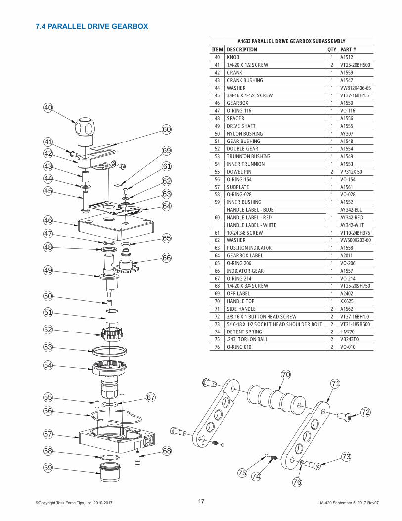
7.4 PARALLEL DRIVE GEARBOX
40
4142
4344
45
46
47
48
49
66
65
6463
62
61
60
69
68
67
50
51
52
53
54
55
56
57
58
5975 74
72
73
7170
76
A1633 PARALLEL DRIVE GEARBOX SUBASSEMBLYITEM DESCRIPTION QTY PART #
40 KNOB 1 A151241 1/4-20 X 1/2 SCREW 2 VT25-20BH50042 CRANK 1 A155943 CRANK BUSHING 1 A154744 WASHER 1 VW812X406-6545 3/8-16 X 1-1/2 SCREW 1 VT37-16BH1.546 GEARBOX 1 A155047 O-RING-116 1 VO-11648 SPACER 1 A155649 DRIVE SHAFT 1 A155550 NYLON BUSHING 1 AY30751 GEAR BUSHING 1 A154852 DOUBLE GEAR 1 A155453 TRUNNION BUSHING 1 A154954 INNER TRUNNION 1 A155355 DOWEL PIN 2 VP312X.5056 O-RING-154 1 VO-15457 SUBPLATE 1 A156158 O-RING-028 1 VO-02859 INNER BUSHING 1 A1552
60HANDLE LABEL - BLUE
1AY342-BLU
HANDLE LABEL - RED AY342-RED HANDLE LABEL - WHITE AY342-WHT
61 10-24 3/8 SCREW 1 VT10-24BH37562 WASHER 1 VW500X203-6063 POSITION INDICATOR 1 A155864 GEARBOX LABEL 1 A201165 O-RING 206 1 VO-20666 INDICATOR GEAR 1 A155767 O-RING 214 1 VO-21468 1/4-20 X 3/4 SCREW 1 VT25-20SH75069 OFF LABEL 1 A240270 HANDLE TOP 1 XX62571 SIDE HANDLE 2 A156272 3/8-16 X 1 BUTTON HEAD SCREW 2 VT37-16BH1.073 5/16-18 X 1/2 SOCKET HEAD SHOULDER BOLT 2 VT31-18SB50074 DETENT SPRING 2 HM77075 .243" TORLON BALL 2 VB243TO76 O-RING 010 2 VO-010
©Copyright Task Force Tips, Inc. 2010-2017 LIA-420 September 5, 2017 Rev0718
8.0 WARRANTYTask Force Tips, Inc., 3701 Innovation Way, Valparaiso, IN 46383-9327 (*TFT*) warrants to the original purchaser of its Oasis Valve (*equipment*), and to anyone to whom it is transferred, that the equipment shall be free from defects in material and workmanship during the fi ve (5) year period from the date of purchase.TFT’s obligation under this warranty is specifi cally limited to replacing or repairing the equipment (or its parts) which are shown by TFT’s examination to be in a defective condition attributable to TFT. To qualify for this limited warranty, the claimant must return the equipment to TFT, at 3701 Innovation Way, Valparaiso, IN 46383-9327, within a reasonable time after discovery of the defect. TFT will examine the equipment. If TFT determines that there is a defect attributable to it, TFT will correct the problem within a reasonable time. If the equipment is covered by this limited warranty, TFT will assume the expenses of repair.If any defect attributable to TFT under this limited warranty cannot be reasonably cured by repair or replacement, TFT may elect to refund the purchase price of the equipment, less reasonable depreciation, in complete discharge of its obligations under this limited warranty. If TFT makes this election, claimant shall return the equipment to TFT free and clear of any liens and encumbrances.This is a limited warranty. The original purchaser of the equipment, any person to whom it is transferred, and any person who is an intended or unintended benefi ciary of the equipment, shall not be entitled to recover from TFT any consequential or incidental damages for injury to person and/or property resulting from any defective equipment manufactured or assembled by TFT. It is agreed and understood that the price stated for the equipment is in part consideration for limiting TFT’s liability. Some states do not allow the exclusion or limitation of incidental or consequential damages, so the above may not apply to you.TFT shall have no obligation under this warranty if the equipment is, or has been, misused or neglected (including failure to provide reasonable maintenance) or if there have been accidents to the equipment or if it has been repaired or altered by someone else.THIS IS A LIMITED EXPRESS WARRANTY ONLY. TFT EXPRESSLY DISCLAIMS WITH RESPECT TO THE EQUIPMENT ALL IMPLIED WARRANTIES OF MERCHANTABILITY AND ALL IMPLIED WARRANTIES OF FITNESS FOR A PARTICULAR PURPOSE. THERE IS NO WARRANTY OF ANY NATURE MADE BY TFT BEYOND THAT STATED IN THIS DOCUMENT.This limited warranty gives you specifi c legal rights, and you may also have other rights which vary from state to state.
9.0 MAINTENANCEThis valve should be disconnected, cleaned and visually inspected inside and out at least quarterly for proper function per NFPA 1962 section 8.2, or as water quality and use may require. Moving parts such as handles, valve ball and couplings should be checked for smooth and free operation. Seals shall be greased as needed with a silicone-based grease such as Dow Corning 112. Any scrapes that expose bare aluminum should be cleaned and touched up with enamel paint such as Rust-Oleum. In particular assure that:
• There is no damage such as cracks or dents• There is no corrosion• The waterway is clear of obstructions
Replace any missing or damaged parts before returning to service. Any repaired device must be tested before being placed in service.
CAUTIONAny alterations to the device and its markings could diminish safety and constitute a misuse of this product
©Copyright Task Force Tips, Inc. 2010-2017 LIA-420 September 5, 2017 Rev0719
9.1 SERVICE TESTINGIn accordance with NFPA 1962 (2013), appliances must be tested a minimum of annually. Nozzles failing any part of this test must be removed from service, repaired and retested upon completion of the repair.
9.1.1 HYDRAULIC TEST The appliance being tested shall be positioned in a protective device or cover capable of holding the appliance and tested to a minimum hydrostatic pressure of 300 psi (20.7 bar or 2070 kPa).Test caps capable of withstanding the required hydrostatic pressure shall be attached to openings, and a device capable of exerting the required hydrostatic pressure shall be attached to the appliance.Appliances with relief valves shall have the relief valve outlet blanked off or otherwise closed during the test.All air shall be bled from the system.The gauge pressure shall be increased by 50 psi (3.45 bar or 345 kPa) increments and held for 30 seconds at each pressure up to the maximum pressure for which the appliance is being tested and held for 1 minute without leakage.
9.1.2 CHECK VALVE TEST If the appliance has a check valve, and the check valve can be pressurized by valves being closed downstream of the check valve, the output side of the check valve shall be hydrostatically pressurized to the maximum working pressure of the appliance.There shall be no leakage through the check valve.NFPA 1962: Standard for the care, use, inspection, service testing, and replacement of fi re hose, couplings, nozzles and fi re hose appliances. (2013 ed., Section 6.3). Quincy, MA: National Fire Protection Agency.
9.1.3 RECORDS A record of testing and repairs must be maintained from the time the nozzle is purchased until it is discarded. Each TFT appliance is engraved with a unique serial number which, if so desired, can be used to identify nozzle for documentation purposes.
The following information, if applicable, must be included on the test record for each nozzle:• Assigned identifi cation number• Manufacturer• Product or model designation• Vendor• Warranty• Hose connection size• Maximum operating pressure• Flow rate or range• Date received and date put in service• Date of each service test and service test results• Damage and repairs, including who made the repairs and the cost of repair parts• Reason removed from service
NFPA 1962: Standard for the care, use, inspection, service testing, and replacement of fi re hose, couplings, nozzles and fi re hose appliances. (2013 ed., Section 6.4.4). Quincy, MA: National Fire Protection Agency.
9.2 REPAIR Factory service is available with repair time seldom exceeding one day in our facility. Factory serviced appliances are repaired by experienced technicians to original specifi cations, fully tested and promptly returned. Repair charges for non-warranty items are minimal. Any returns should include a note as to the nature of the problem and whom to reach in case of questions.Repair parts and service procedures are available for those wishing to perform their own repairs. Task Force Tips assumes no liability for damage to equipment or injury to personnel that is a result of user service. Contact the factory or visit the web site at www.tft.com for parts lists, exploded views, test procedures and troubleshooting guides.
For additional information on care, maintenance and testing, refer to: NFPA 1962: Standard for the Care, Use, Inspection, Service Testing, and Replacement of Fire Hose, Couplings, Nozzles, and Fire Hose Appliances, 2013 Edition
CAUTION
Any alterations to the device and its markings could diminish safety and constitute a misuse of this product.
10.0 ANSWERS TO YOUR QUESTIONS We appreciate the opportunity of serving you and making your job easier. If you have any problems or questions, our toll-free “Hydraulics Hotline”, 800-348-2686, is normally available to you 24 hours a day, 7 days a week.

©Copyright Task Force Tips, Inc. 2010-2017 LIA-420 September 5, 2017 Rev07
TASK FORCE TIPS, INC.MADE IN USA • www.tft.com
3701 Innovation Way, Valparaiso, IN 46383-9327 USA800-348-2686 • 219- 462-6161 • Fax 219-464-7155
11.0 OPERATION and INSPECTION CHECKLISTBEFORE EACH USE, appliances must be inspected to this checklist:
• All valves open and close fully and smoothly• Waterway is clear of obstructions• There is no damage to any thread or other connection• All locks and hold-down devices work properly• The pressure setting on the relief valve (if so equipped) is set correctly• Gaskets are in good repair• There is no obvious damage such as missing, broken or loose parts• There is no damage to the appliance (e.g. dents, cracks, corrosion, or other defects that could impair operation)• All swiveling elements rotate freely• There is no corrosion on any surface• There are no missing, worn out or broken lugs on couplings• Hose is securely attached
BEFORE BEING PLACED BACK IN SERVICE, appliances must be inspected to this list:• All valves open and close smoothly and fully.• he waterway is clear of obstructions.• There is no damage to any thread or other type connection.• The pressure setting of the relief valve, if any, is set correctly.• All locks and hold-down devices work properly.• Internal gaskets are in accordance with NFPA 1962 (2013) Section 7.2.• There is no damage to the appliance (e.g., dents, cracks, corrosion, or other defects that could impair operation).• All swiveling connections rotate freely.• There are no missing parts or components.• The marking for maximum operating pressure is visible.• There are no missing, broken, or worn lugs on couplings.
NFPA 1962: Standard for the care, use, inspection, service testing, and replacement of fi re hose, couplings, nozzles and fi re hose appliances. (2013 ed., Section 6.2.1). Quincy, MA: National Fire Protection Agency.
WARNINGAny appliance failing any part of the inspection checklist is unsafe and must have the problem corrected before use. Operating a appliance that fails any of the above inspections is a misuse of this equipment.