Embed Size (px)
Citation preview
SEF Muffler
DPF Regeneration Station
Emissions Device Monitor
Thermal Wrap
Junction Box
This manual is property of the owner. Leave with the unit when installation and start-up are complete. Donaldson Company reserves the right to change design and specifications without prior notice.
Do not make any system modifications or adjustments that would alter the original retrofit installation. Modifications may not meet California Air Resources Board (CARB) Executive Order requirements, be considered illegal devices and may result in denial of warranty coverage.
Consult your Donaldson certified emissions dealer if you have questions regarding the installation, operation, maintenance or warranty.
Illustrations are for reference only as actual product may vary.
This is the safety alert symbol. It is used to alert you to potential personal injury hazards. Obey all safety messages that follow this symbol to avoid possible injury or death.
OWNER’S MANUALInstallation, Operation and Maintenance Information
SEMI-ACTIVE ELECTRIC FILTER (SEF)MUFFLER SYSTEMManual Number P232575 Rev 2
2 Semi-Active Electric Filter (SEF) Muffler Systems Owner’s Manual - P232575 Rev 2
Donaldson Retrofit Emissions System
SEF Muffler System ..................................................... 3
Abbreviation Key ......................................................... 4
ARB Disclaimer............................................................ 4
Introduction .................................................................. 5SEF Muffler ......................................................................... 5
Pre-Installation Requirements ............................................ 5
Junction Box ....................................................................... 7
EDM .................................................................................... 7
DPF Regeneration Station .................................................. 8
Lock-Out/Tag-Out ............................................................ 8
Installation ................................................................... 8Vertical Muffler Installation................................................ 9
Remove the Existing Muffler .......................................... 9
Install the SEF Muffler .................................................... 9
Device Identification ..................................................... 10
Horizontal Muffler Installation ......................................... 10
Remove the Existing Muffler ........................................ 10
Install the SEF Muffler .................................................. 10
Junction Box Installation .................................................. 11
EDM Installation ............................................................... 12
DPF Regeneration Station Installation ............................. 12
Installation Checklist ........................................................ 13
Semi-Active Electric Filter (SEF) ............................ 14
Installer and Data ...................................................... 15Theory of Operation .......................................................... 15
Basic Regeneration Station Logic .................................... 16
Operation of the DPF Regeneration Station ..................... 16
DPF Regeneration Station Controls .................................. 17
Contents
Maintenance and Service ....................................... 18Filter Maintenance ........................................................... 18
Conditions That May Plug A DPF Muffler Prematurely ... 18
How to Regenerate a Dirty DPF ........................................ 18
Reset the EDM .................................................................. 19
Time Between SEF System Regenerations ...................... 19
Filter Ash Cleaning Interval .............................................. 19
DPF Section Cleaning Method & Process ........................ 19
Filter Cleaning Instructions ............................................... 20
Record Filter Service ........................................................ 20
Routine Inspection ........................................................... 21
Disposal Information ........................................................ 21
Spare Parts ....................................................................... 21
DPF Regeneration Station & Spare Parts ..................... 21
SEF Diesel Particulate Filter* ....................................... 21
SEF Muffler Service Parts ............................................. 21
SEF Troubleshooting Guide ............................................... 22
DPF Swapping and Re-Designation ....................... 24
SEF Limited Warranty ............................................... 27Warranty Coverage ........................................................... 27
Owners Warranty Responsibility ...................................... 27
Installation Warranty Responsibility ................................ 27
Maintenance that May Void Warranty ............................. 28
Semi-Active Electric Filter (SEF) Muffler Systems Owner’s Manual - P232575 Rev 2 3
Donaldson Retrofit Emissions System
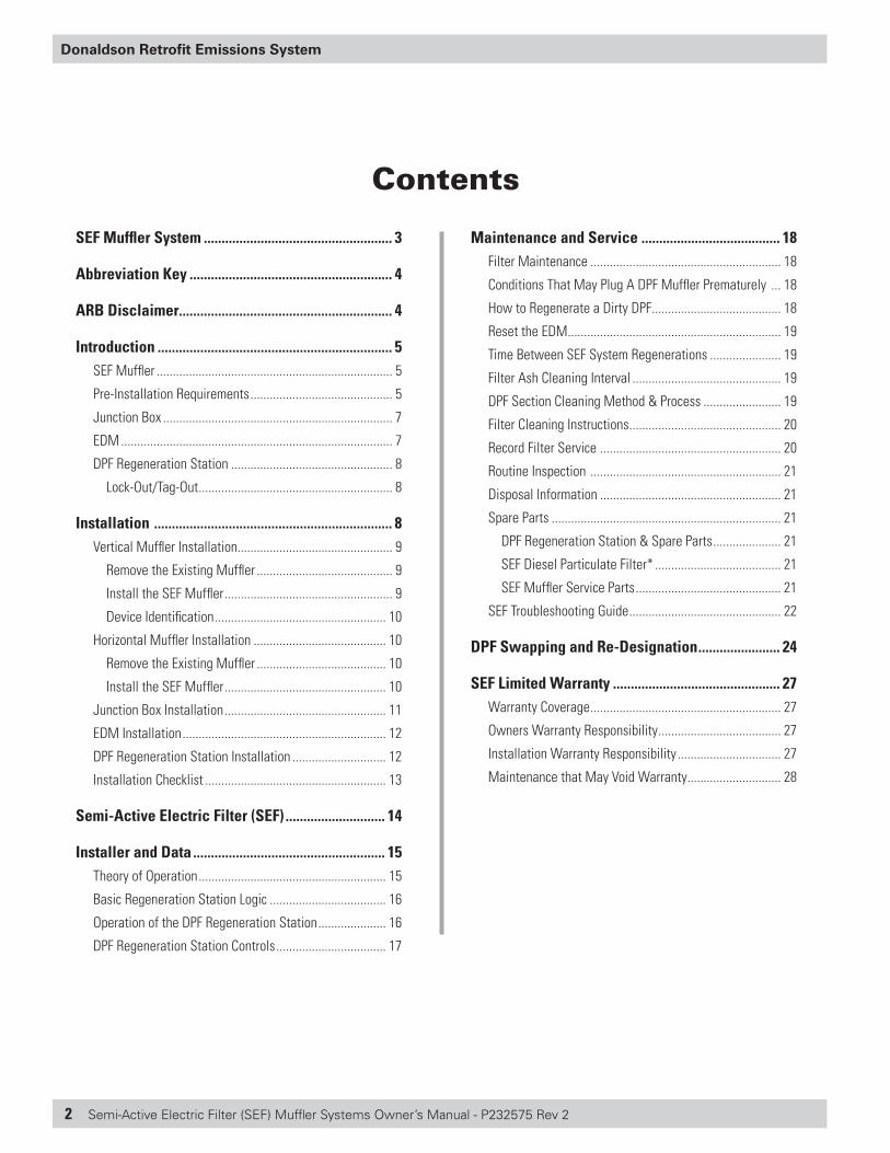
SEF Muffler System
Major components of the Donaldson SEF Muffler System
Regeneration Station Control Panel• Operator interface for monitoring the status of
automated DPF regeneration cycles
Emissions Device Monitor (EDM)• Monitors status of SEF Muffler• Indicates when DPF regeneration is required
Junction Box • Houses connections for DPF regeneration (power
and thermocouple) • Install on vehicle in accessible location
DPF Regeneration Station• Provides automated control
of SEF Muffler regeneration cycle
• Controls up to two DPF regeneration cycles simultaneously
• Requires electrical power and compressed air supplies Regeneration Cable-25 ft.
• Provides power, thermocouple and air connections to SEF Muffler for DPF regeneration cycle
SEF Muffler• Eliminates PM and gaseous emissions from diesel exhaust• Requires heat regeneration cycle to burn PM in the DPF• Up to 4 times heavier than OEM muffler
4 Semi-Active Electric Filter (SEF) Muffler Systems Owner’s Manual - P232575 Rev 2
Donaldson Retrofit Emissions System
ARB Disclaimer
Your Right to Maintenance Information
The Air Resources Board requires that Donaldson Company, Inc. provide detailed maintenance information for the diesel emissions control system upon delivery to the end-user pursuant to section 2706(h)(2), Title 13, California Code of Regulations, at no additional cost to the owner. If you do not already have this information, contact Donaldson Emission Retrofit Technical Support at 1 (866) 817-8733.
The Importance of Engine Maintenance
Proper engine maintenance is critical for the proper functioning of your diesel emissions control strategy. Failure to document proper engine maintenance, including oil consumption records, may be grounds for denial of a warranty claim for a failed component of a diesel emission control strategy.
The Importance of Properly Maintaining a Diesel Emission Control Strategy
Proper maintenance is critical for the diesel emission control strategy to function as intended. Failure to document proper diesel emission control strategy maintenance, including cleaning and/or ash removal of the system, replacement of consumables, and replacement of broken/failed parts, may be grounds for denial of a warranty claim for a failed component of a diesel emission control strategy. See page 27-28 for warranty information.
Abbreviation Key
ASTM = American Society for Testing and Materials
CARB = California Air Resources Board
CJ-4 = Engine oils made for high-performance diesel engines and designed to meet 2007 on-highway exhaust emission standards. API (American Petroleum Institute) CJ-4 oils exceed previous performance requirements and are specifically designed to protect emission control systems when used with ULSD fuel
COMS = Communication port for diagnostics (EDM)
DCI = Donaldson Company, Inc.
DECS = Diesel Emissions Control System
DOC = Diesel Oxidation Catalyst
DPF = Diesel Particulate Filter
EDM = Emissions Device Monitor
EFN = Engine Family Number
EPA = Environmental Protection Agency
HP = Horsepower
Hrs = Hours
IOM = Installation and Owner’s Manual
LNF = Low NO2 Filter
LXF = Low NOx Filter
mV = Millivolts
MY = Model Year
NEMA = National Electrical Manufacturers Association
OEM = Original Equipment Manufacturer
PM = Particulate Matter
RPM = Revolutions per Minute
RTV SILICONE = Room temperature vulcanization silicone used as a sealant
sec = Seconds
SECM = Small Electronic Control Module
SEF = Semi-Active Electric Filter
SUBSTRATES = Internal filtration components of the SEF system
Temp = Temperature
ULSD = Ultra Low Sulfur Diesel
V = Volts
VAC = Volts Alternating Current
VIN = Vehicle Identification Number
WAT = Weighted Average Temperature
Semi-Active Electric Filter (SEF) Muffler Systems Owner’s Manual - P232575 Rev 2 5
Donaldson Retrofit Emissions System
Pre-Installation Requirements
This section includes pre-installation requirements and considerations for the four major system components:
• SEF Muffler• Junction Box• EDM• DPF Regeneration Station
The content of this section draws attention to topics and information that should be considered BEFORE you start installing. The information includes mounting tips and considerations, procedures and techniques that may be required and may impact how and where you install components of the system.
In order to maximize the diesel emission control system performance, the installation must meet the requirements in the following sections. Failure to follow these instructions may void the warranty and may lead to device failure.
Introduction
The Donaldson Semi-Active Electric Filter (SEF) Muffler System is designed to reduce emissions from in-use diesel engines. Besides reducing diesel particulate matter (PM) emissions by over 90%, the SEF Muffler is also effective at reducing hydrocarbon and carbon monoxide emissions.
The SEF Muffler System is made up of the following assemblies:
SEF Muffler Kit• SEF Muffler • Junction Box• Emissions Device Monitor (EDM)• Serialized Muffler and Engine Tags
DPF Regeneration Station • Automated Control Panel• Regeneration Cables
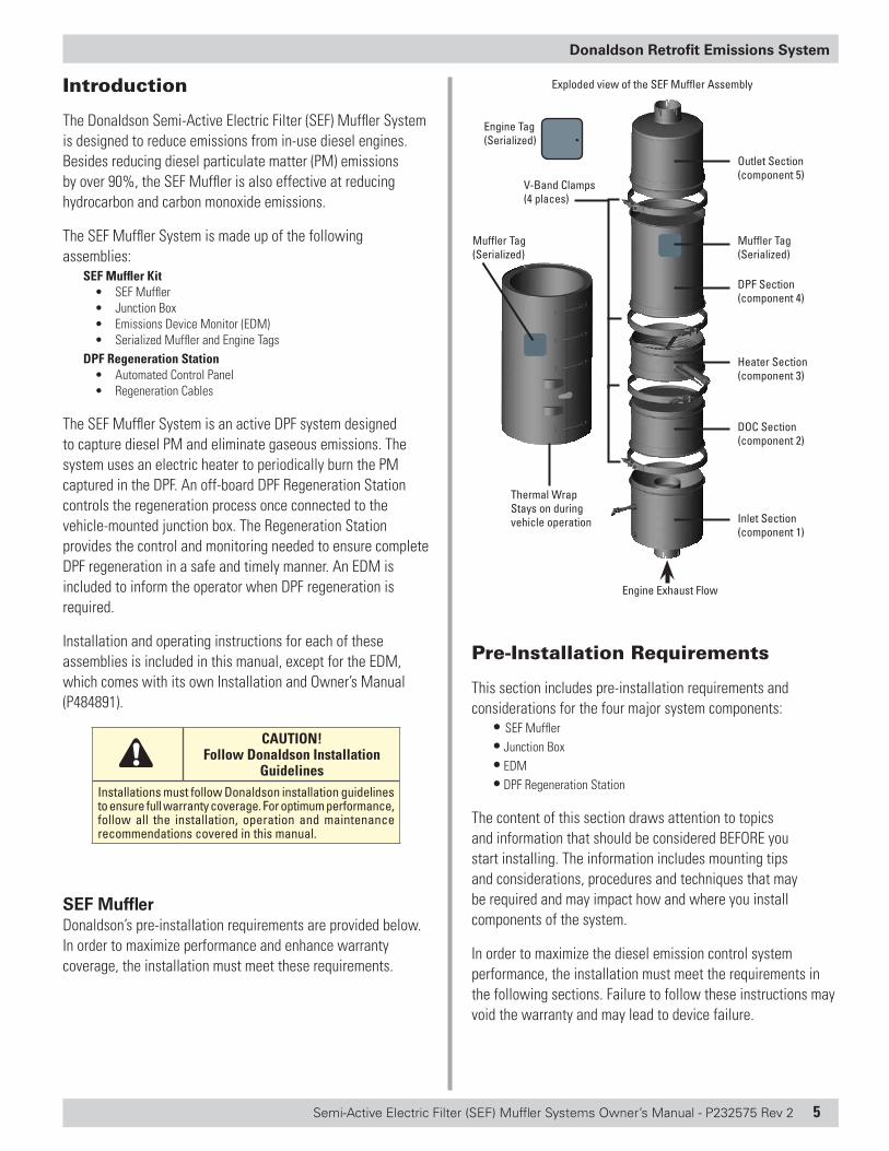
The SEF Muffler System is an active DPF system designed to capture diesel PM and eliminate gaseous emissions. The system uses an electric heater to periodically burn the PM captured in the DPF. An off-board DPF Regeneration Station controls the regeneration process once connected to the vehicle-mounted junction box. The Regeneration Station provides the control and monitoring needed to ensure complete DPF regeneration in a safe and timely manner. An EDM is included to inform the operator when DPF regeneration is required.
Installation and operating instructions for each of these assemblies is included in this manual, except for the EDM, which comes with its own Installation and Owner’s Manual (P484891).
CAUTION! Follow Donaldson Installation
GuidelinesInstallations must follow Donaldson installation guidelines to ensure full warranty coverage. For optimum performance, follow all the installation, operation and maintenance recommendations covered in this manual.
SEF MufflerDonaldson’s pre-installation requirements are provided below. In order to maximize performance and enhance warranty coverage, the installation must meet these requirements.
Outlet Section(component 5)
V-Band Clamps (4 places)
DPF Section(component 4)
Heater Section(component 3)
DOC Section(component 2)
Inlet Section(component 1)
Thermal WrapStays on during vehicle operation
Exploded view of the SEF Muffler Assembly
Engine Exhaust Flow
Engine Tag(Serialized)
Muffler Tag (Serialized)
Muffler Tag (Serialized)
6 Semi-Active Electric Filter (SEF) Muffler Systems Owner’s Manual - P232575 Rev 2
Donaldson Retrofit Emissions System
Application Pre-Assessment
Verify that the application PASSED the Donaldson Application Pre-assessment conducted by a Certified Emissions Dealer. The pre-assessment worksheet and opacity test results need to be forwarded to Donaldson upon warranty registration.
The application pre-assessment confirms the following:
• The engine family number (EFN) for the vehicle is included in the California ARB-Approved Engine Family listing of Executive Order
• Vehicle and engine has been properly maintained
• Vehicle passed the pre-assessment visual system inspection
• Opacity test results collected meet Donaldson requirements (based on SAE J1667 test specification)
• Vehicle engine duty cycle meets the application temperature criteria. The temperature profile should not exceed the passive system criteria.
NOTE
The engine must be inspected by a qualified technician to verify the engine is operating within the engine OEM’s specifications. If the engine does not meet specifications, necessary repairs must be made prior to installation. The technician must document compliance on the warranty registration form. Failure to comply may void the warranty. Poor engine performance will reduce the operating interval between DPF regeneration cycles.
Proper SEF Muffler Application
Be sure the engine meets the SEF Muffler flow limits for your application. SEF Mufflers have a maximum flow limit of 2700 CFM. SEF Muffler assemblies will be applied according to: • Engine flow at 2700 CFM or below • Approved CARB engine list • Muffler assemblies rated for engines below 275 hp. • Muffler assemblies rated for engines above 275 hp.
Application of the device on engines outside of these parameters will result in shorter intervals between regenerations, affect exhaust system performance and may result in poor engine performance. Improper application may also result in regulatory fines and/or other enforcement action.
Fuel Requirement
The SFF Muffler System requires the use of ULSD Fuel (15 ppm or less sulfur content) that meets ASTM D975. BioULSD (20% biodiesel/80% ULSD) per ASTM D6751 diesel fuel specifications may also be used. Fuel additives are not permitted and may void your warranty.
Engine Lube Oil Requirement
The SEF Muffler requires the use of engine lube oil that meets CJ-4 specifications (low ash). The engine must NOT be consuming oil higher than a rate of one quart per 500 miles.
Fuel Penalty
The effect of a SEF System on fuel consumption is negligible. SAE Paper 810858 – ‘Fuel Efficient Exhaust Systems’ outlines fuel consumption of a turbocharged diesel engine with respect to backpressure. It states that fuel consumption will increase 0.5% for every 1" Hg backpressure over the manufacturer’s specification. The SEF System will increase backpressure on the engine compared to a stock muffler. However, the expected increase will be less than 1" Hg on average. Thus, the expected fuel consumption increase will be ~0.5%. Given the vast differences in duty cycles for on-road vehicles, this would not be a measurable difference.
Backpressure Increase
The SEF system could increase the nominal engine backpressure by 20" H2O (1.46" Hg) compared to stock exhaust system. When the SEF Muffler is plugged from engine inspection or yearly cleaning, the engine backpressure can increase to 100" H2O (7.36" Hg) or 127" H2O (9.34" Hg).
Noise Level ControlExpected noise level of the SEF system will be equal to or less than the stock exhaust system.
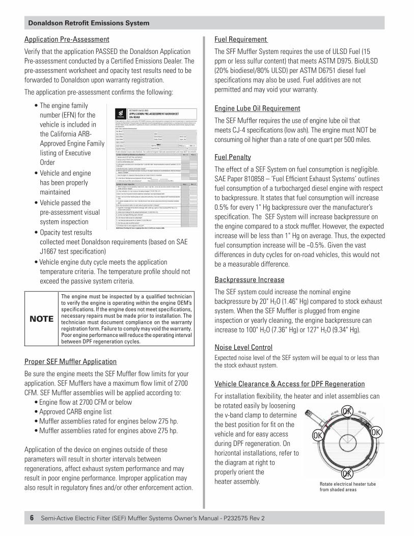
Vehicle Clearance & Access for DPF Regeneration
For installation flexibility, the heater and inlet assemblies can be rotated easily by loosening the v-band clamp to determine the best position for fit on the vehicle and for easy access during DPF regeneration. On horizontal installations, refer to the diagram at right to properly orient the heater assembly. Rotate electrical heater tube
from shaded areas
OKOK
OK
OK
Semi-Active Electric Filter (SEF) Muffler Systems Owner’s Manual - P232575 Rev 2 7
Donaldson Retrofit Emissions System
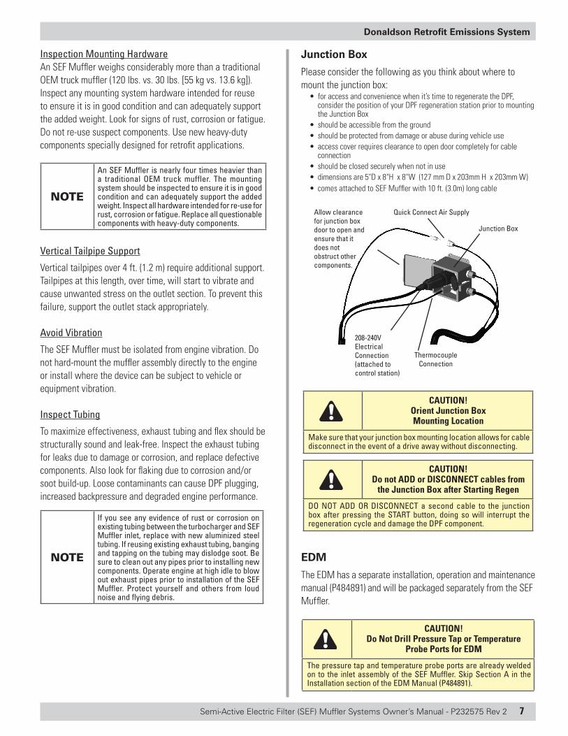
Junction Box
Please consider the following as you think about where to mount the junction box:
• for access and convenience when it’s time to regenerate the DPF, consider the position of your DPF regeneration station prior to mounting the Junction Box
• should be accessible from the ground • should be protected from damage or abuse during vehicle use• access cover requires clearance to open door completely for cable
connection• should be closed securely when not in use • dimensions are 5"D x 8"H x 8"W (127 mm D x 203mm H x 203mm W)• comes attached to SEF Muffler with 10 ft. (3.0m) long cable
Quick Connect Air Supply
208-240V Electrical Connection (attached to control station)
Junction Box
Thermocouple Connection
Allow clearance for junction box door to open and ensure that it does not obstruct other components.
CAUTION! Orient Junction Box Mounting Location
Make sure that your junction box mounting location allows for cable disconnect in the event of a drive away without disconnecting.
CAUTION! Do not ADD or DISCONNECT cables from
the Junction Box after Starting Regen
DO NOT ADD OR DISCONNECT a second cable to the junction box after pressing the START button, doing so will interrupt the regeneration cycle and damage the DPF component.
EDM
The EDM has a separate installation, operation and maintenance manual (P484891) and will be packaged separately from the SEF Muffler.
CAUTION! Do Not Drill Pressure Tap or Temperature
Probe Ports for EDM
The pressure tap and temperature probe ports are already welded on to the inlet assembly of the SEF Muffler. Skip Section A in the Installation section of the EDM Manual (P484891).
Inspection Mounting HardwareAn SEF Muffler weighs considerably more than a traditional OEM truck muffler (120 lbs. vs. 30 lbs. [55 kg vs. 13.6 kg]). Inspect any mounting system hardware intended for reuse to ensure it is in good condition and can adequately support the added weight. Look for signs of rust, corrosion or fatigue. Do not re-use suspect components. Use new heavy-duty components specially designed for retrofit applications.
NOTE
An SEF Muffler is nearly four times heavier than a traditional OEM truck muffler. The mounting system should be inspected to ensure it is in good condition and can adequately support the added weight. Inspect all hardware intended for re-use for rust, corrosion or fatigue. Replace all questionable components with heavy-duty components.
Vertical Tailpipe Support
Vertical tailpipes over 4 ft. (1.2 m) require additional support. Tailpipes at this length, over time, will start to vibrate and cause unwanted stress on the outlet section. To prevent this failure, support the outlet stack appropriately.
Avoid Vibration
The SEF Muffler must be isolated from engine vibration. Do not hard-mount the muffler assembly directly to the engine or install where the device can be subject to vehicle or equipment vibration.
Inspect Tubing
To maximize effectiveness, exhaust tubing and flex should be structurally sound and leak-free. Inspect the exhaust tubing for leaks due to damage or corrosion, and replace defective components. Also look for flaking due to corrosion and/or soot build-up. Loose contaminants can cause DPF plugging, increased backpressure and degraded engine performance.
NOTE
If you see any evidence of rust or corrosion on existing tubing between the turbocharger and SEF Muffler inlet, replace with new aluminized steel tubing. If reusing existing exhaust tubing, banging and tapping on the tubing may dislodge soot. Be sure to clean out any pipes prior to installing new components. Operate engine at high idle to blow out exhaust pipes prior to installation of the SEF Muffler. Protect yourself and others from loud noise and flying debris.
8 Semi-Active Electric Filter (SEF) Muffler Systems Owner’s Manual - P232575 Rev 2
Donaldson Retrofit Emissions System
DPF Regeneration Station
Items to Consider:• Unit weight: 117 lbs. / 53 Kg (with cables) • Mounting Space Requirement: 24"W x 21"H x 9"D • Clearance: (1) Allow 20" clearance for door to open; (2) minimum 12"
clearance on three remaining sides• The control station display panel should be mounted at eye level • Locate the DPF Regen Station so that two vehicles can park within 25
feet of the station for the DPF regeneration process as the cables are 25 ft. long.
• If installed outside or for exterior access, a cover or awning is required to protect the control panel.
• If installing indoors, make sure to use an exhaust removal system that will vent the exhaust outdoors.
• The DPF Regeneration Station requires a clean, dry compressed air source: 100 PSI @ 4.5 SCFM
• Minimum air supply requirements for a stand alone SEF Regeneration Station: 3 HP, 60 gallon, single stage air compressor
• Only a certified electrician should make connections. Follow all local electrical codes.
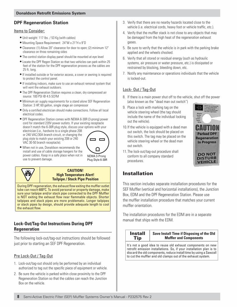
• DPF Regeneration Station comes with NEMA 6-30R (3-prong) power cord for standard 220V power outlets. If your existing receptacle doesn’t match the 6-30R plug style, discuss your options with your electrician (i.e., hardwire to a single phase 208 or 240 VAC/30A branch circuit, or changing the plug style to match your existing 208 or 240 VAC 30-50 branch receptacle).
• When not in use, Donaldson recommends the install and use of cable storage hangers for the power cables. Keep in a safe place when not in use to prevent damage.
CAUTION! High Temperature Alert!
Tailpipe / Stack Pipe Position
During DPF regeneration, the exhaust flow exiting the muffler outlet tube can reach 600ºC. To avoid personal or property damage, make sure your tailpipe and/or stack pipe connected to the DPF Muffler is NOT exiting the exhaust flow near flammable objects. Shorter tailpipes and stack pipes are more problematic. Longer tailpipes or stack pipes by design, should provide adequate length to cool the exhaust flow.
Lock-Out/Tag-Out Instructions During DPF Regeneration
The following lock-out/tag-out instructions should be followed just prior to starting an SEF DPF Regeneration.
Pre Lock-Out / Tag-Out
1. Lock-out/tag-out should only be performed by an individual authorized to tag out the specific piece of equipment or vehicle.
2. Be sure the vehicle is parked within close proximity to the DPF Regeneration Station so that the cables can reach the Junction Box on the vehicle.
NEMA 3-Prong Plug Style 6-30R
3. Verify that there are no nearby hazards located close to the vehicle (i.e. electrical cords, heavy foot or vehicle traffic, etc.).
4. Verify that the muffler stack is not close to any objects that may be damaged from the high heat of the regeneration exhaust gases.
5. Be sure to verify that the vehicle is in park with the parking brake applied and the wheels chocked.
6. Verify that all stored or residual energy (such as hydraulic systems, air pressure or water pressure, etc.) is dissipated or restrained by blocking, bleeding down, etc.
7. Notify any maintenance or operations individuals that the vehicle is locked-out.
Lock- Out / Tag-Out
8. If there is a main power shut off to the vehicle, shut off the power (also known as the “dead man out switch”)
9. Place a lock with marking tag on the vehicle steering wheel (the tag should include the name of the individual locking out the vehicle).
10. If the vehicle is equipped with a dead man out switch, the lock should be placed on this switch. The tag may be placed on the vehicle steering wheel or the dead man out switch.
11. The lock-out/tag-out procedure shall conform to all company standard procedures.
Installation
This section includes separate installation procedures for the SEF Muffler (vertical and horizontal installations), the Junction Box, EDM and the DPF Regeneration Station. Please use the muffler installation procedure that matches your current muffler orientation.
The installation procedures for the EDM are in a separate manual that ships with the EDM.
Install Tip
Save Install Time if Disposing of the Old Muffler and Components
It's not a good idea to reuse old exhaust components on new retrofit emission installations. So, if your installation plan is to discard the old components, reduce install time by using a Sawzall to cut the muffler and old clamps out of the exhaust system.
Semi-Active Electric Filter (SEF) Muffler Systems Owner’s Manual - P232575 Rev 2 9
Donaldson Retrofit Emissions System
Vertical Muffler Installation
Remove the Existing Muffler
1. Loosen stack clamp at muffler outlet (top). Remove stack and clamp.
2. Loosen tubing clamp at muffler inlet (bottom). 3. Loosen clamps on flex tubing. Remove clamps, flex and inlet
elbow.4. Loosen muffler and heat shield mounting bands. Remove and
discard muffler and heat shield. 5. Operate engine to blow scale or rust contaminants from exhaust
tubing.
Install the SEF Muffler1. Prepare the muffler mounting area. Ensure the mounting stanchion
or mast is robust enough to support the weight of an SEF Muffler. A mast extension is typically required to accommodate the added length of the SEF Muffler (+6 in. / +15cm). Be sure to allow enough clearance for the thermal wrap to fit between the mast and the muffler body.
Replace any existing mounting parts that appear rusted, damaged or of questionable strength with heavy-duty parts. Mounting components must be strong enough to adequately support the 120 lbs. (55 kg) muffler weight. Use new heavy-duty mounting brackets, bands, supports and/or stanchion. Donaldson offers many components designed specifically to handle the added weight of emissions retrofit devices.
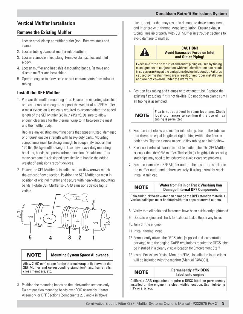
2. Ensure the SEF Muffler is installed so that flow arrows match the exhaust flow direction. Position the SEF Muffler on mast in position of original muffler and secure with heavy-duty mounting bands. Rotate SEF Muffler so CARB emissions device tag is visible.
5 4 3 12
NOTE Mounting System Space Allowance
Allow 2" (50 mm) space for the thermal wrap to fit between the SEF Muffler and corresponding stanchion/mast, frame rails, cross members, etc.
3. Position the mounting bands on the inlet/outlet sections only. Do not position mounting bands over DOC Assembly, Heater Assembly, or DPF Sections (components 2, 3 and 4 in above
illustration), as that may result in damage to those components and interfere with thermal wrap installation. Ensure exhaust tubing lines up properly with SEF Muffler inlet/outlet sections to avoid damage to muffler.
CAUTION! Avoid Excessive Force on Inlet
and Outlet Piping!
Excessive force on the inlet and outlet piping caused by tubing misalignment in conjunction with vehicle vibration can result in stress cracking at the emissions device inlet/outlet. Failures caused by misalignment are a result of improper installation and are not covered under the warranty.
4. Position flex tubing and clamps onto exhaust tube. Replace the existing flex tubing if it is not flexible. Do not tighten clamps until all tubing is assembled.
NOTEFlex is not approved in some locations. Check local ordinances to confirm if the use of flex tubing is permitted.
5. Position inlet elbow and muffler inlet clamp. Locate flex tube so that there are equal lengths of rigid tubing (within the flex) on both ends. Tighten clamps to secure flex tubing and inlet elbow.
6. Reconnect exhaust stack onto muffler outlet tube. The SEF Muffler is longer than the OEM muffler. The height (or length) of the existing stack pipe may need to be reduced to avoid clearance problems.
7. Position clamp over SEF Muffler outlet tube. Insert the stack into the muffler outlet and tighten securely. If using a straight stack, install a rain cap.
NOTE Water from Rain or Truck Washing Can Damage Internal DPF Components
Rain and truck wash water can damage the DPF retention materials. Vertical tailpipes must be fitted with rain caps or curved outlets.
8. Verify that all bolts and fasteners have been sufficiently tightened.
9. Operate engine and check for exhaust leaks. Repair any leaks.
10. Turn off the engine.
11. Install thermal wrap.
12. Permanently attach the DECS label (supplied in documentation package) onto the engine. CARB regulations require the DECS label be installed in a clearly visible location for Enforcement Staff.
13. Install Emissions Device Monitor (EDM). Installation instructions will be included with the monitor (Manual P484891).
NOTE Permanently affix DECS label onto engine
California ARB regulations require a DECS label be permanently installed on the engine in a clear, visible location. Use high-temp RTV or a screw.
10 Semi-Active Electric Filter (SEF) Muffler Systems Owner’s Manual - P232575 Rev 2
Donaldson Retrofit Emissions System
CAUTION! Additional Support is Required on Vertical Tailpipes over 4 ft. (1.2m)!
Vertical tailpipes over 4 ft.(1.2 m) require additional support. Tailpipes at this length, over time, will start to vibrate and cause unwanted stress on the outlet section. To prevent this failure, support the outlet stack appropriately.
Device Identification
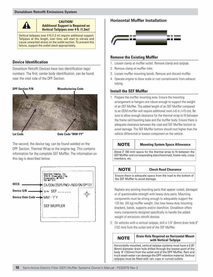
Donaldson Retrofit Devices have two identification tags/numbers. The first, center body identification, can be found near the inlet side of the DPF Section.
DPF Section P/N Manufacturing Code
Lot Code Date Code "WW-YY"
The second, the device tag, can be found welded on the DPF Section, Thermal Wrap or the engine tag. This contains information for the complete SEF Muffler. The information on this tag is described below:
DECS
Device S/N
Device Date Code
SEF MUFFLER
SEF
1
Horizontal Muffler Installation
Remove the Existing Muffler1. Loosen clamp at muffler outlet. Remove clamp and tailpipe.2. Remove clamp at muffler inlet.3. Loosen muffler mounting bands. Remove and discard muffler. 4. Operate engine to blow scale or rust contaminants from exhaust
tubing.
Install the SEF Muffler1. Prepare the muffler mounting area. Ensure the mounting
arrangement or hangers are robust enough to support the weight of an SEF Muffler. The added length of an SEF Muffler compared to an OEM muffler will require additional room (+6 in./+15 cm). Be sure to allow enough clearance for the thermal wrap to fit between the frame rail/mounting base and the muffler body. Ensure there is adequate clearance between the road and SEF Muffler bottom to avoid damage. The SEF Muffler bottom should rest higher than the vehicle differential or lowest component on the vehicle.
NOTE Mounting System Space Allowance
Allow 2" (50 mm) space for the thermal wrap to fit between the SEF Muffler and corresponding stanchion/mast, frame rails, cross members, etc.
NOTE Check Road Clearance
Ensure there is adequate space from the road to the bottom of the SEF Muffler to avoid damage.
Replace any existing mounting parts that appear rusted, damaged or of questionable strength with heavy-duty parts. Mounting components must be strong enough to adequately support the 120 lbs. (55 kg) muffler weight. Use new heavy-duty mounting brackets, bands, supports and/or stanchion. Donaldson offers many components designed specifically to handle the added weight of emissions retrofit devices.
2. On vehicles with a vertical tailpipe, drill a 1/4" (6mm) drain hole 6" (152 mm) from the outlet end of the SEF Muffler.
NOTE Drain Hole Required on Horizontal Mount with Vertical Tailpipe
Horizontally-mounted, vertical tailpipe systems must have a 0.25" (6mm) diameter drain hole drilled through the lowest point of the body 6" (152mm) from the outlet end of the DPF Muffler. Rain and truck wash water can damage the DPF retention material. Vertical tailpipes must be fitted with rain caps or curved outlets.
Semi-Active Electric Filter (SEF) Muffler Systems Owner’s Manual - P232575 Rev 2 11
Donaldson Retrofit Emissions System
3. Position and secure the SEF Muffler with heavy-duty brackets and mounting bands. Ensure the SEF Muffler is installed so that flow arrows match the exhaust flow direction. Rotate the muffler so the drain hole is oriented downward. Ensure the mounting bands do not cover the drain hole.
Position the mounting bands on the muffler inlet and outlet sections only. Do not position mounting bands over DOC or DPF sections as that can result in damage to those components and interfere with thermal wrap installation.
See ‘Vehicle Clearance and Access for DPF Regeneration’ section for a detailed explanation of the heater assembly orientation in a horizontal installation.
Ensure exhaust tubing lines up properly with muffler inlet and outlet joints to avoid damage to muffler. Be sure to allow enough clearance for the thermal wrap to fit between the frame and the SEF Muffler body.
CAUTION! Avoid Excessive Force on Inlet
and Outlet Piping!Excessive force on the inlet and outlet piping caused by tubing misalignment in conjunction with vehicle vibration can result in stress cracking at the emissions device inlet/outlet. Failures caused by misalignment are a result of improper installation and are not covered under the warranty.
4. Position inlet tubing and clamp on muffler inlet tube and tighten clamp.
5. Install tailpipe and secure clamp on muffler outlet/tailpipe joint.
6. Verify that all bolts and fasteners have been sufficiently tightened.
7. Operate the engine and check for exhaust leaks. Repair any leaks.
8. Turn off the engine.
9. Install thermal wrap.
10. Permanently attach the DECS label (supplied in documentation package) onto the engine. CARB regulations require the DECS engine tag be installed in a location clearly visible to Enforcement staff.
11. Install Emissions Device Monitor (EDM). Installation instructions will be included with monitor (Manual P484891).
NOTE Permanently affix DECS label onto engine
California ARB regulations require a DECS label be permanently installed on the engine in a clear, visible location. Use high-temp RTV or a screw.
Junction Box Installation
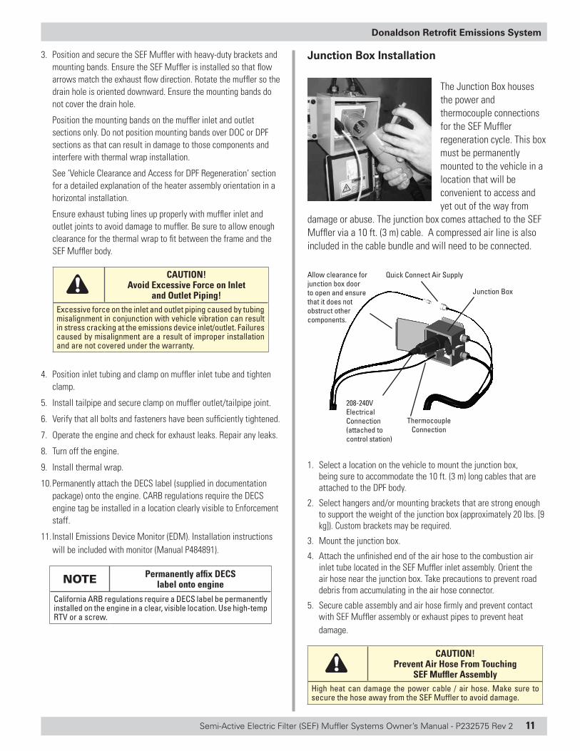
The Junction Box houses the power and thermocouple connections for the SEF Muffler regeneration cycle. This box must be permanently mounted to the vehicle in a location that will be convenient to access and yet out of the way from
damage or abuse. The junction box comes attached to the SEF Muffler via a 10 ft. (3 m) cable. A compressed air line is also included in the cable bundle and will need to be connected.
Quick Connect Air Supply
208-240V Electrical Connection (attached to control station)
Junction Box
Thermocouple Connection
Allow clearance for junction box door to open and ensure that it does not obstruct other components.
1. Select a location on the vehicle to mount the junction box, being sure to accommodate the 10 ft. (3 m) long cables that are attached to the DPF body.
2. Select hangers and/or mounting brackets that are strong enough to support the weight of the junction box (approximately 20 lbs. [9 kg]). Custom brackets may be required.
3. Mount the junction box.
4. Attach the unfinished end of the air hose to the combustion air inlet tube located in the SEF Muffler inlet assembly. Orient the air hose near the junction box. Take precautions to prevent road debris from accumulating in the air hose connector.
5. Secure cable assembly and air hose firmly and prevent contact with SEF Muffler assembly or exhaust pipes to prevent heat damage.
CAUTION!Prevent Air Hose From Touching
SEF Muffler AssemblyHigh heat can damage the power cable / air hose. Make sure to secure the hose away from the SEF Muffler to avoid damage.
12 Semi-Active Electric Filter (SEF) Muffler Systems Owner’s Manual - P232575 Rev 2
Donaldson Retrofit Emissions System
EDM Installation
The EDM In-Cab Display should be installed in a visible area inside the cab. The Donaldson EDM is a required key component of Donaldson DPF systems as it records and analyzes DPF operating conditions. Temperature and backpressure readings are continuously recorded to aid in analyzing vehicle operating trends and to support troubleshooting. A date and time module (DTM) adds dates and time to the log file download. An EDM kit is included with all Donaldson SEF Muffler kits.
To enhance DTM capabilities, a replacement battery is incorporated to maintain settings during periods when the vehicle is in storage or the battery is disconnected.
COMS Connection Access - Position for Easy Access
• A technician will need to access the connector labeled “COMS” when the DPF is serviced or cleaned. Make sure the COMS connector is easy to access.
• If retrofitting several vehicles in a fleet, consider positioning the COMS connector in the same general area so the technicians can locate it easier.
Mounting Location - SECM• If installing the EDM on a rear engine vehicle, you will need to order
the 50 foot sensor harness (P231739) separately to reach the sensors.
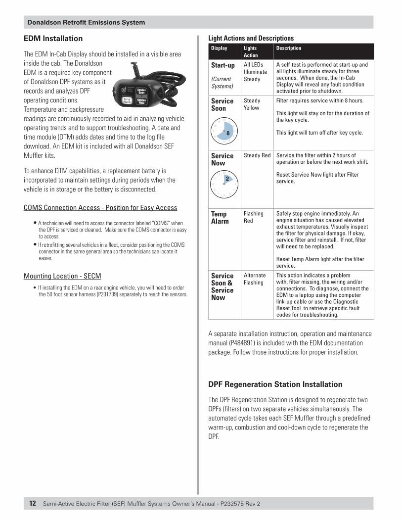
Light Actions and DescriptionsDisplay Lights
ActionDescription
Start-up
(Current Systems)
All LEDs Illuminate Steady
A self-test is performed at start-up and all lights illuminate steady for three seconds. When done, the In-Cab Display will reveal any fault condition activated prior to shutdown.
Service Soon
HOURS HOURS
Steady Yellow
Filter requires service within 8 hours.
This light will stay on for the duration of the key cycle.
This light will turn off after key cycle.
Service Now
HOURS HOURS
Steady Red Service the filter within 2 hours of operation or before the next work shift.
Reset Service Now light after Filter service.
Temp Alarm
Flashing Red
Safely stop engine immediately. An engine situation has caused elevated exhaust temperatures. Visually inspect the filter for physical damage. If okay, service filter and reinstall. If not, filter will need to be replaced.
Reset Temp Alarm light after the filter service.
Service Soon & Service Now
Alternate Flashing
This action indicates a problem with, filter missing, the wiring and/or connections. To diagnose, connect the EDM to a laptop using the computer link-up cable or use the Diagnostic Reset Tool to retrieve specific fault codes for troubleshooting.
A separate installation instruction, operation and maintenance manual (P484891) is included with the EDM documentation package. Follow those instructions for proper installation.
DPF Regeneration Station Installation
The DPF Regeneration Station is designed to regenerate two DPFs (filters) on two separate vehicles simultaneously. The automated cycle takes each SEF Muffler through a predefined warm-up, combustion and cool-down cycle to regenerate the DPF.
Semi-Active Electric Filter (SEF) Muffler Systems Owner’s Manual - P232575 Rev 2 13
Donaldson Retrofit Emissions System
Installation of DPF Regeneration Station
CAUTION!Install only with Certified Electrician
Installation of the Thermal Regeneration Control System must be completed by a Certified Electrician. Failure to use a certified electrician may result in personal injury, damage to the unit or to property.
1. To allow owner to easily see and operate the control station display panel, mount control panel at eye level.
2. Install a hood or awning, if mounted outdoors.
3. Connect panel to an electrical power source. Installation of the control station should only be completed by a trained, certified electrician. A control circuit electrical schematic is included in this manual. Follow all local electric and building codes. See ‘DPF Regeneration Station’ Section for additional information.
4. Connect to compressed air supply. Install air dryer/filter to avoid damage. Air supply must be a constant 100 psi.
Installation Checklist
SEF Muffler
� SEF Muffler mounted in proper exhaust flow direction. As shown by the flow arrows on the muffler segments.
� SEF Muffler isolated from engine/frame rail vibration by use of flex pipe, bellows, or mounting clamp isolators
� Thermal wrap in position (over the DPF and heater assembly) and secure.
� Vertical tailpipes over 4 ft. (1.2m) require additional support
� Thermal wrap clear of other parts, and does not interfere with other vehicle or engine parts when vehicle is in operation
� New hardware and clamps installed per this manual
� All SEF Muffler mounting hardware and clamps are tightened
� No visible exhaust leaks in the system
� Rain cap installed on vertical installations.
� Labels clearly visible on device
Junction Box
� Junction Box mounted in location that can be easily accessed during service
� Junction Box door has clearance for opening and closing
� Mounting bolts or brackets tightened
� Air quick connection properly mounted near Junction Box
� Air hose mounted and connected to the SEF Muffler inlet section
� No loose compressed air, thermocouple, or electrical lines
� All compressed air, thermocouple, and electrical power lines mounted safely, securely, and away from hot or moving parts
Emissions Device Monitor (EDM)
� Refer to EDM installation and operation manual (P484891)
� The EDM will include a date and time module (DTM) allowing backpressure and temperature data to be aligned with time of occurrence
� Vehicle operators trained on new In-Cab Display and alerts
� Complete Vehicle Setup: Connect laptop with COMS port and enter information into SECM “Vehicle Setup” (VIN, Diesel Emission Control Strategy [DECS], Serial No., install date, etc.)
See the EDM manual (P484891) for instructions
Program Compliance
� Warranty card filled out completely and filed electronically
� ARB engine tag permanently affixed to the engine with RTV silicone in a visible location
� End user has warranty document, preliminary temperature data log, Donaldson recommendation letter, copy of ARB Executive Order and this manual for their records
� Pre-assessment complete
14 Semi-Active Electric Filter (SEF) Muffler Systems Owner’s Manual - P232575 Rev 2
Donaldson Retrofit Emissions System
Activate the WarrantyFor regulatory reporting and warranty registration purposes, Donaldson Company requires the installer/dealer to complete and submit the warranty for the vehicle or equipment owner on our Warranty Registration web site.
A Warranty Registration Worksheet is included in the documentation packet Register the new installation within 30 days using our on-line warranty registration site at: http://pwww.donaldson.com
Emissions Retrofit DocumentationRetain all emissions retrofit documentation on each vehicle, including:
• Vehicle temperature data / profile form
• Donaldson response letter that approved the retrofit application
• Date of installation
• Mileage / hours at install
• Installation and owner information
• Part number
• Serial number
• DPF service and cleaning records
SEMI-ACTIVE ELECTRIC FILTER (SEF)
Connecting control station to SEF Muffler
Connection between the SEF control station and the SEF Muffler assembly will be through a 25 ft. cable assembly (2X) at the control station with three (3) connections:
a. Power – Large blue electric plug
b. Air – Black hose with quick coupler
c. Temperature – Yellow with two (2) prong plug
2. A Junction box (located on vehicle) is a 6"x 6" NEMA4 gray enclosure mounted in an area close to the SEF Muffler. There are receptacles in the enclosure for power and thermocouple termination. The air connection is made with mating quick couplers.
Regeneration control station pre-startup checks
Prior to energizing the control station enclosure:
1. Ensure the power plug is disconnected or the knife switch providing power to the enclosure is OFF.
2. Check the internal circuit breakers inside the enclosure. To do this:
a. The main enclosure disconnect, located in the center of the door must in the OFF position.
b. Open the door latch located on the center right by inserting a straight blade screwdriver or a coin into the slot and rotate 90 degrees counter clockwise.
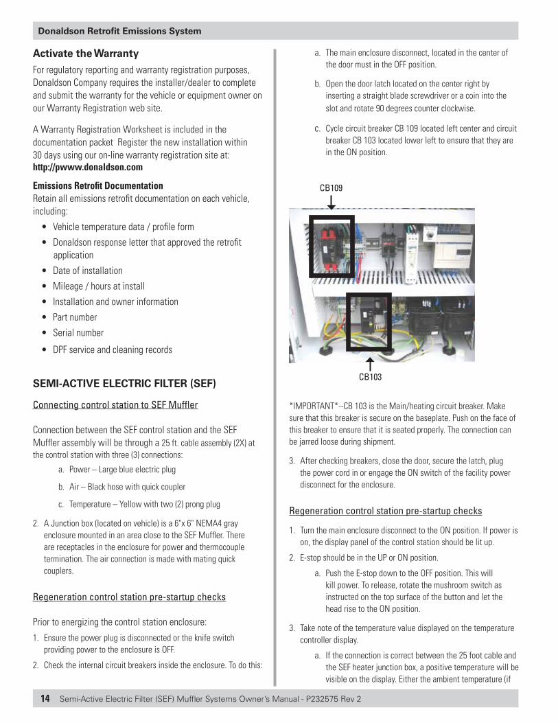
c. Cycle circuit breaker CB 109 located left center and circuit breaker CB 103 located lower left to ensure that they are in the ON position.
CB103
CB109
*IMPORTANT*--CB 103 is the Main/heating circuit breaker. Make sure that this breaker is secure on the baseplate. Push on the face of this breaker to ensure that it is seated properly. The connection can be jarred loose during shipment.
3. After checking breakers, close the door, secure the latch, plug the power cord in or engage the ON switch of the facility power disconnect for the enclosure.
Regeneration control station pre-startup checks
1. Turn the main enclosure disconnect to the ON position. If power is on, the display panel of the control station should be lit up.
2. E-stop should be in the UP or ON position.
a. Push the E-stop down to the OFF position. This will kill power. To release, rotate the mushroom switch as instructed on the top surface of the button and let the head rise to the ON position.
3. Take note of the temperature value displayed on the temperature controller display.
a. If the connection is correct between the 25 foot cable and the SEF heater junction box, a positive temperature will be visible on the display. Either the ambient temperature (if
Semi-Active Electric Filter (SEF) Muffler Systems Owner’s Manual - P232575 Rev 2 15
Donaldson Retrofit Emissions System
the muffler is cold) or the temperature of a cooling muffler after engine shutdown will be shown.
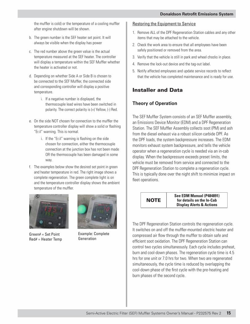
b. The green number is the SEF heater set point. It will always be visible when the display has power
c. The red number above the green value is the actual temperature measured at the SEF heater. The controller will display a temperature within the SEF Muffler whether the heater is activated or not.
d. Depending on whether Side A or Side B is chosen to be connected to the SEF Muffler, the connected side and corresponding controller will display a positive temperature.
i. If a negative number is displayed, the thermocouple lead wires have been switched in polarity. The correct polarity is (+) Yellow, (-) Red.
e. On the side NOT chosen for connection to the muffler the temperature controller display will show a solid or flashing “Er.il” warning. This is normal.
i. If the “Er.il” warning is flashing on the side chosen for connection, either the thermocouple connection at the junction box has not been made OR the thermocouple has been damaged in some way.
f. The examples below show the desired set point in green and heater temperature in red. The right image shows a complete regeneration. The green complete light is on and the temperature controller display shows the ambient temperature of the muffler.
Green# = Set PointRed# = Heater Temp
Example: Complete Generation
Restoring the Equipment to Service
1. Remove ALL of the DPF Regeneration Station cables and any other items that may be attached to the vehicle.
2. Check the work area to ensure that all employees have been safely positioned or removed from the area.
3. Verify that the vehicle is still in park and wheel chocks in place.
4. Remove the lock-out device and the tag-out label.
5. Notify affected employees and update service records to reflect that the vehicle has completed maintenance and is ready for use.
Installer and Data
Theory of Operation
The SEF Muffler System consists of an SEF Muffler assembly, an Emissions Device Monitor (EDM) and a DPF Regeneration Station. The SEF Muffler Assembly collects soot (PM) and ash from the diesel exhaust via a robust silicon carbide DPF. As the DPF loads, the system backpressure increases. The EDM monitors exhaust system backpressure, and tells the vehicle operator when a regeneration cycle is needed via an in-cab display. When the backpressure exceeds preset limits, the vehicle must be removed from service and connected to the DPF Regeneration Station to complete a regeneration cycle. This is typically done over the night shift to minimize impact on fleet operations.
NOTESee EDM Manual (P484891)
for details on the In-Cab Display Alerts & Actions
The DPF Regeneration Station controls the regeneration cycle. It switches on and off the muffler-mounted electric heater and compressed air flow through the muffler to obtain safe and efficient soot oxidation. The DPF Regeneration Station can control two cycles simultaneously. Each cycle includes preheat, burn and cool-down phases. The regeneration cycle time is 4.5 hrs for one unit or 7.0 hrs for two. When two are regenerated simultaneously, the cycle time is reduced by overlapping the cool-down phase of the first cycle with the pre-heating and burn phases of the second cycle.
16 Semi-Active Electric Filter (SEF) Muffler Systems Owner’s Manual - P232575 Rev 2
Donaldson Retrofit Emissions System
Basic Regeneration Station Logic
• Correct Power to all components is assumed.• Is the main power disconnect on the front of the enclosure ON and the
E-stop ON?• Are the internal breakers/fuses on or OK?• After five minutes, if the heater controller is not sensing temperature
above 500°F the cycle is aborted and the flashing light is illuminated. Refer to the Troubleshooting Guide for solutions.
• If at anytime the temperature exceeds 1400°F, the cycle is aborted and the red flashing light is illuminated.
• After 15 minutes of core warm-up (heater temperature is greater than 500° F and less than 1400° F) the compressed air solenoid is energized and pulses 1 second ON and 2 seconds OFF.
• If air pressure drops below 60 PSI for 3 seconds, the regeneration cycle is aborted (yellow flashing light). See the Troubleshooting Guide.
• After 2 hours and 30 minutes the SEF heater power relay is de-energized for the A or B filter being heated and the air pulse will continue at the same 1 second ON and 2 second OFF rate with a continuous yellow cool down light illuminated.
• If both A and B filters are selected for regeneration, the filter B energizes at this point if filter A has been de-energized.
• After 4.5 hours the compressed air solenoid for filter A or B is de-energized and the cleaning cycle is complete for that filter. If filter A and B are selected for regeneration, the compressed air solenoid for filter B will stay on for another 2.5 hours (.5 hours of heating cycle with air pulses and 2 hours of air “cool down” pulses).
• When regeneration cycles are complete the green light flashes.• In the event the regeneration needs to be interrupted, push the
emergency stop button. This action will abort the regeneration cycles. This should be done only in cases of emergency. Shutting down the system is not recommended unless absolutely necessary. Structural damage can occur to the systems substrates.
To ensure proper functioning of these products, Donaldson preventive maintenance and service procedures must be incorporated into your regular vehicle maintenance routines.
Operation of the DPF Regeneration Station
The DPF Regeneration Station is designed to clean a single DPF on a truck or two DPFs on two separate trucks at the same time. The length of the cleaning cycle duration is dependant on the number of trucks connected (at the same time).
Trucks Filters Regen Time
1 Truck System A 4.5 hours
1 Truck System B 4.5 hours
2 Trucks System A & B 7 hours
CAUTION! Do not ADD or DISCONNECT cables from
the Junction Box after Starting Regen
DO NOT ADD OR DISCONNECT a second cable to the junction box after pressing the START button, doing so will interrupt the regeneration cycle and damage the DPF component.
CAUTION! DO NOT Change the Selector Switch Once
Regen Cycle Has Started!
DO NOT change the selector switch once cycle is started–doing so will interrupt the regeneration cycle and damage the DPF component.
CAUTION!DO NOT Stop the Regen Process for truck to connect a second truck to the station!
Stopping the regen cleaning procedure at any time during the entire cycle may damage the DPF component. The DPF can easily be damaged if the heating cycle is shut off . Please note that the DPF is a very expensive component within the system and would have to be replaced if damaged occurred due stopping the programmed regeneration cycle.
CAUTION! Well ventilated area required for regeneration
Do not regenerate the SEF system in a closed area without dedicated power ventilation for the exhaust
CAUTION! High Temperature Alert
Make sure thermal wrap is installed on DPF Muffler BEFORE regen cycle starts.
The body of the DPF muffler becomes very hot during DPF Regeneration. The thermal wrap included with the SEF Muffler kit must remain in place to avoid injury and protect nearby components from heat.
Semi-Active Electric Filter (SEF) Muffler Systems Owner’s Manual - P232575 Rev 2 17
Donaldson Retrofit Emissions System
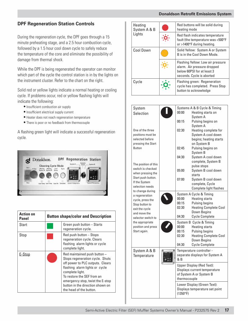
DPF Regeneration Station Controls
During the regeneration cycle, the DPF goes through a 15 minute preheating stage, and a 2.5 hour combustion cycle, followed by a 1.5 hour cool down cycle to safely reduce the temperature of the core and eliminate the possibility of damage from thermal shock.
While the DPF is being regenerated the operator can monitor which part of the cycle the control station is in by the lights on the instrument cluster. Refer to the chart on the right.
Solid red or yellow lights indicate a normal heating or cooling cycle. If problems occur, red or yellow flashing lights will indicate the following:
• Insufficient combustion air supply• Insufficient electrical supply current• Heater does not reach regeneration temperature• There is poor or no feedback from thermocouple
A flashing green light will indicate a successful regeneration cycle.
Action on Panel Button shape/color and Description
Start Green push button – Starts regeneration cycle.
Stop Red push button – Stops regeneration cycle. Clears flashing alarm lights or cycle complete light.
E-Stop Red maintained push button – Stops regeneration cycle. Shuts off power to PLC outputs. Clears flashing alarm lights or cycle complete light.To restore the SEF from an emergency stop, twist the E-stop button in the direction shown on the head of the button.
Heating System A & B Lights
Red buttons will be solid during heating mode
Red flash indicates temperature fault (the temperature was <500°F or >1400°F during heating.
Cool Down Solid Yellow: System A or System B is in the Cool Down Mode.
Flashing Yellow: Low air pressure alarm. Air pressure dropped below 60PSI for at least 3 seconds. Cycle is aborted
Cycle Flashing green: Regeneration cycle has completed. Press Stop button to acknowledge
System Selection
One of the three positions must be selected before pressing the Start Button
The position of this switch is checked when pressing the Start push button. If the System selection needs to change during a regeneration cycle, press the Stop button to exit the cycle and move the selector switch to the appropriate position and press Start again.
Systems A & B Cycle & Timing00:00 Heating starts on
System A00:15 Pulsing begins on
System A02:30 Heating complete for
System A cool down begins; heating starts on System B
02:45 Pulsing begins on System B
04:30 System A cool down complete, System B pulse stops
05:00 System B cool down starts
07:00 System B cool down complete, Cycle Complete light flashes
System A Cycle & Timing00:00 Heating starts00:15 Pulsing begins02:30 Heating Complete Cool
Down Begins04:30 Cycle Complete
System B Cycle & Timing00:00 Heating starts00:15 Pulsing begins02:30 Heating Complete Cool
Down Begins04:30 Cycle Complete
System A & B Temperature
Temperature controller - separate displays for System A & B
Upper Display (Red Text): Displays current temperature of System A or System B thermocouple
Lower Display (Green Text): Displays temperature set point (1350°F)
18 Semi-Active Electric Filter (SEF) Muffler Systems Owner’s Manual - P232575 Rev 2
Donaldson Retrofit Emissions System
Maintenance and Service
Filter Maintenance
The DPF Section of the SEF Muffler captures soot and ash from diesel exhaust. Over time the DPF will load and will need to be regenerated by using the SEF Muffler regeneration station. While the electric heater burns off the soot, the ash slowly builds up. Eventually, the DPF must be removed to be ash-cleaned. This should occur annually or every 50,000 miles, whichever comes first. See Filter Cleaning instructions for more information.
The DPF does not require maintenance other than routine cleaning by means of the DPF Regeneration Station and ash cleaning or PM.
Preventive maintenance recommendations during normally scheduled vehicle maintenance.
1. Inspect the emissions device, exhaust piping and mounting brackets.
2. Look for leaks, structural failures (cracks), and loose or missing fasteners.
3. Repair or replace defective parts as appropriate.
NOTE Do Not Use Fuels Blended with Lube Oil
Engine oil must not be blended with the engine's fuel since the oil may cause reduced emissions performance and deposits in the filter that may cause higher backpressure, plugging and reduced engine performance and may result in the denial of warranty.
NOTE For Electronically Controlled Engines
Electronically controlled engines are certified with a specific fuel and electronic program based on engine configuration and model year. Use only the fuel and electronic program specified for your engine. Using the incorrect fuel and/or electronic program may cause excessive soot generation and filter plugging, and may void the warranty.
CAUTION! Lube Oil
To protect against DPF failure and/or plugging, ensure that the engine is not consuming oil at a rate higher than specified by the engine manufacturer. Use low ash oils, when possible. Do not use fuel blended with lube oil. Check with your local Donaldson dealer to review additives before use.
Conditions That May Plug a DPF Muffler Prematurely
• The conditions below, if not corrected, may result in denial of the SEF warranty
• Improper engine maintenance• Engine operation at low load or idling for extended periods
of time• Engine failures that increase PM emissions including,
leaking or failed injectors, leaking turbocharger seals and/or intake manifold leaks
• Engine failures that emit contaminants that may foul the pre-filter or DPF
• Improper engine calibration for the specific fuel type being used
• The above conditions may face plug the pre-filter. To clean the pre-filter, use a shop vacuum with a bristle attachment to gently clean the face. The pre-filter does NOT require regular service during its life under normal operating conditions. The DPF section in the SEF Muffler will need routine service.
How to Regenerate a Dirty DPF
CAUTION! High Temperature Alert!
Tailpipe / Stack Pipe Position
During DPF regeneration, the exhaust flow existing the muffler outlet tube can reach 600ºC. To avoid personal or property damage, make sure your tailpipe and/or stack pipe connected to the DPF Muffler is NOT exiting the exhaust flow near flammable objects. Shorter tailpipes and stack pipes are more problematic. Longer tailpipes or stack pipes by design, should provide adequate length to cool the exhaust flow.
NOTE Do Not Start Vehicle During Regeneration
Never attempt to start the vehicle while the DPF filter is being regenerated. Damage to the filter and other components may occur.
NOTE Do Not Stop the Regeneration Cycle Unless of Emergency
Do not use the emergency stop button as a means to pre-maturely end the regeneration cycle. Damage to the filter may occur due to thermal shock. The emergency stop button should only be used in emergency situations.
Semi-Active Electric Filter (SEF) Muffler Systems Owner’s Manual - P232575 Rev 2 19
Donaldson Retrofit Emissions System
Once a vehicle has been docked at the control station, use the following steps to complete a regeneration:
1. Three items will need to be plugged in: the power cable, the thermocouple cable, and the combustion air hose. System A or B, or both may be used.
2. The engine of the vehicle must be shut off and remain off for the entire duration of the regeneration cycle.
3. Look at the instrument cluster and verify that there is a temperature reading on the System A Temperature or System B Temperature read-out (depending on which is plugged in). If temperature reading is “Er. il”, an error code, the thermocouple is missing or broken. Restore or repair part.
4. Verify that the emergency stop button is not depressed.
NOTE Two Vehicles Can be Regenerated at the Same Time!
The DPF Regeneration Station is designed to regenerate two filters on two separate vehicles simultaneously.
5. Turn the Selector switch to the System A or System B. The System A switch is connected to the cables on the bottom left of the regen station, the System B switch is connected to the cables on the bottom right of the box.
6. Press the start button.
7. A single regen cycle is complete after 4.5 hours, two regens (System A & B ) take about 7 hours. The green complete button will illuminate and flash when regen cycle is complete.
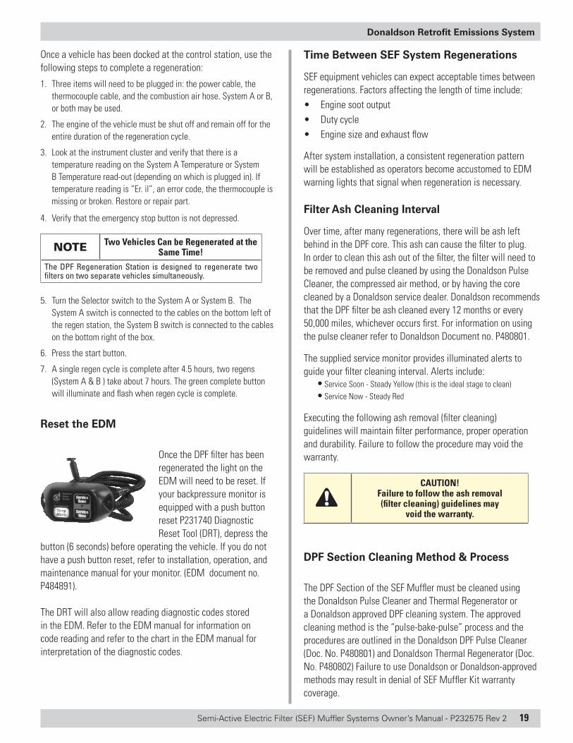
Reset the EDM
Once the DPF filter has been regenerated the light on the EDM will need to be reset. If your backpressure monitor is equipped with a push button reset P231740 Diagnostic Reset Tool (DRT), depress the
button (6 seconds) before operating the vehicle. If you do not have a push button reset, refer to installation, operation, and maintenance manual for your monitor. (EDM document no. P484891).
The DRT will also allow reading diagnostic codes stored in the EDM. Refer to the EDM manual for information on code reading and refer to the chart in the EDM manual for interpretation of the diagnostic codes.
Time Between SEF System Regenerations
SEF equipment vehicles can expect acceptable times between regenerations. Factors affecting the length of time include:• Engine soot output• Duty cycle• Engine size and exhaust flow
After system installation, a consistent regeneration pattern will be established as operators become accustomed to EDM warning lights that signal when regeneration is necessary.
Filter Ash Cleaning Interval
Over time, after many regenerations, there will be ash left behind in the DPF core. This ash can cause the filter to plug. In order to clean this ash out of the filter, the filter will need to be removed and pulse cleaned by using the Donaldson Pulse Cleaner, the compressed air method, or by having the core cleaned by a Donaldson service dealer. Donaldson recommends that the DPF filter be ash cleaned every 12 months or every 50,000 miles, whichever occurs first. For information on using the pulse cleaner refer to Donaldson Document no. P480801.
The supplied service monitor provides illuminated alerts to guide your filter cleaning interval. Alerts include:
• Service Soon - Steady Yellow (this is the ideal stage to clean)• Service Now - Steady Red
Executing the following ash removal (filter cleaning) guidelines will maintain filter performance, proper operation and durability. Failure to follow the procedure may void the warranty.
CAUTION! Failure to follow the ash removal (filter cleaning) guidelines may
void the warranty.
DPF Section Cleaning Method & Process
The DPF Section of the SEF Muffler must be cleaned using the Donaldson Pulse Cleaner and Thermal Regenerator or a Donaldson approved DPF cleaning system. The approved cleaning method is the “pulse-bake-pulse” process and the procedures are outlined in the Donaldson DPF Pulse Cleaner (Doc. No. P480801) and Donaldson Thermal Regenerator (Doc. No. P480802) Failure to use Donaldson or Donaldson-approved methods may result in denial of SEF Muffler Kit warranty coverage.
20 Semi-Active Electric Filter (SEF) Muffler Systems Owner’s Manual - P232575 Rev 2
Donaldson Retrofit Emissions System
Do not use any wet or liquid type cleaning system to clean the DPF.
CAUTION! Do not use STEAM or LIQUID DETERGENTS
to clean the DPF Section.Donaldson does not recommend cleaning the DPF Section with steam and/or other detergents. Use of these products may damage and/or deactivate the DPF and may result in denial of warranty coverage.
CAUTION!DO NOT Pulse Clean a HOT DPF Section
The DPF inlet/outlet surface must be below 200ºF (93ºC) before placing into the unit. Pulse cleaning a HOT DPF may result in fire leading to personal injury or property damage.
CAUTION!DO NOT Pulse Clean a DPF Section with
Compressed Air > 70 psi!Do not clean the DPF section with compressed air greater than 70 psi. Doing so may damage the DPF section and result in denial of warranty coverage.
The recommended method and process to clean the DPF Section includes these steps:
Before Cleaning• Measure and record weight of DPF Section • Test and record backpressure of DPF Section in Donaldson Pulse
Cleaner
DPF Section Cleaning• Pulse clean in Donaldson Pulse Cleaner (removes ash and soot) • Bake (thermally regenerate) • Pulse clean DPF Section when cool (removes additional ash created
during the regeneration cycle)
After Cleaning • Test and record backpressure of DPF Section in Donaldson Pulse
Cleaner• Measure and record weight of DPF Section
Filter Cleaning Instructions - DPF Remove and Replace
CAUTION! Wear Protective Gear During Cleaning
A dust mask, gloves and safety glasses should be worn while performing the cleaning process.
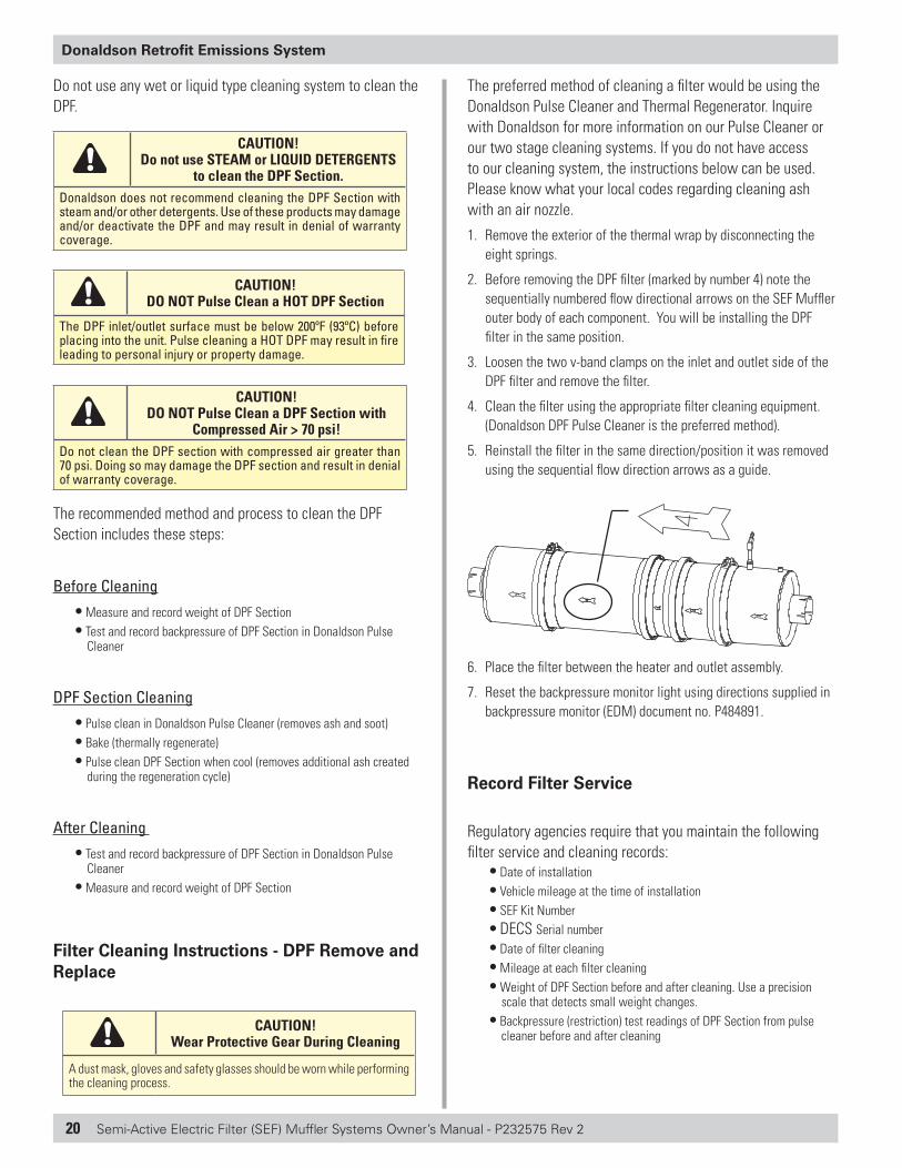
The preferred method of cleaning a filter would be using the Donaldson Pulse Cleaner and Thermal Regenerator. Inquire with Donaldson for more information on our Pulse Cleaner or our two stage cleaning systems. If you do not have access to our cleaning system, the instructions below can be used. Please know what your local codes regarding cleaning ash with an air nozzle.
1. Remove the exterior of the thermal wrap by disconnecting the eight springs.
2. Before removing the DPF filter (marked by number 4) note the sequentially numbered flow directional arrows on the SEF Muffler outer body of each component. You will be installing the DPF filter in the same position.
3. Loosen the two v-band clamps on the inlet and outlet side of the DPF filter and remove the filter.
4. Clean the filter using the appropriate filter cleaning equipment. (Donaldson DPF Pulse Cleaner is the preferred method).
5. Reinstall the filter in the same direction/position it was removed using the sequential flow direction arrows as a guide.
6. Place the filter between the heater and outlet assembly.
7. Reset the backpressure monitor light using directions supplied in backpressure monitor (EDM) document no. P484891.
Record Filter Service
Regulatory agencies require that you maintain the following filter service and cleaning records:
• Date of installation • Vehicle mileage at the time of installation • SEF Kit Number • DECS Serial number • Date of filter cleaning • Mileage at each filter cleaning• Weight of DPF Section before and after cleaning. Use a precision
scale that detects small weight changes.• Backpressure (restriction) test readings of DPF Section from pulse
cleaner before and after cleaning
Semi-Active Electric Filter (SEF) Muffler Systems Owner’s Manual - P232575 Rev 2 21
Donaldson Retrofit Emissions System
Routine Inspections During Vehicle Service
The following preventive maintenance recommendations should be conducted during normally scheduled vehicle maintenance.
1. Inspect the emissions device, exhaust piping and mounting brackets.
2. Look for leaks, structural failures (cracks) and loose or missing fasteners.
3. Repair or replace defective parts, as appropriate.
Disposal Information
The DOC in the SEF Muffler system uses a precious metal catalyst to reduce carbon monoxide, hydrocarbons and diesel particulate matter emissions. Typical metals may include platinum, palladium and rhodium. These materials can be recycled from damaged or deactivated DPFs. Please dispose of SEF Muffler System and waste in accordance with federal, state and local regulations and laws; recycle when possible.
Spare Parts
DPF Regeneration Station & Spare Parts
Description Part No.
25 ft. Regeneration Cable P232342
Instrument Cluster Lights & Switch Kit P232343
Temperature Controller P232344
Circuit Breaker and Mounting Base P232345
Air Manifold Assembly P232346
Fuses, 5-Pack P232347
Contactor P232348
Din-A-Mite Controller P232349
Relay P232350
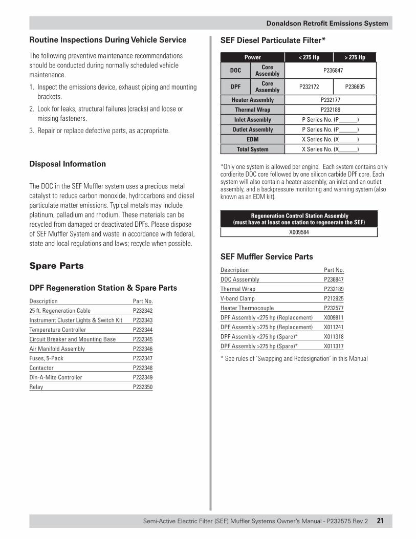
SEF Diesel Particulate Filter*
Power < 275 Hp > 275 Hp
DOC Core Assembly P236847
DPF Core Assembly P232172 P236605
Heater Assembly P232177
Thermal Wrap P232189
Inlet Assembly P Series No. (P______)
Outlet Assembly P Series No. (P______)
EDM X Series No. (X______)
Total System X Series No. (X______)
*Only one system is allowed per engine. Each system contains only cordierite DOC core followed by one silicon carbide DPF core. Each system will also contain a heater assembly, an inlet and an outlet assembly, and a backpressure monitoring and warning system (also known as an EDM kit).
Regeneration Control Station Assembly (must have at least one station to regenerate the SEF)
X009584
SEF Muffler Service Parts
Description Part No.
DOC Asssembly P236847
Thermal Wrap P232189
V-band Clamp P212925
Heater Thermocouple P232577
DPF Assembly <275 hp (Replacement) X009811
DPF Assembly >275 hp (Replacement) X011241
DPF Assembly <275 hp (Spare)* X011318
DPF Assembly >275 hp (Spare)* X011317
* See rules of ‘Swapping and Redesignation’ in this Manual
22 Semi-Active Electric Filter (SEF) Muffler Systems Owner’s Manual - P232575 Rev 2
Donaldson Retrofit Emissions System
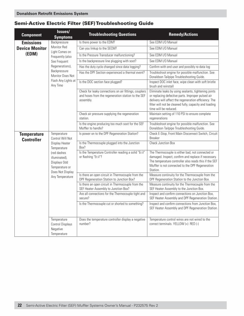
Semi-Active Electric Filter (SEF) Troubleshooting Guide
ComponentIssues/
SymptomsTroubleshooting Questions Remedy/Actions
Emissions Device Monitor
(EDM)
Backpressure Monitor Red Light Comes on Frequently (also See Frequent Regenerations), Backpressure Monitor Does Not Flash Any Lights at Any Time
Is there power to the EDM? See EDM I/O Manual
Can you linkup to the SECM? See EDM I/O Manual
Is the Pressure Transducer malfunctioning? See EDM I/O Manual
Is the backpressure line plugging with soot? See EDM I/O Manual
Has the duty cycle changed since data logging? Confirm with end user and possibly re-data log
Has the DPF Section experienced a thermal event? Troubleshoot engine for possible malfunction. See Donaldson Tailpipe Troubleshooting Guide.
Is the DOC section face plugged? Inspect DOC inlet face, wipe clean with soft bristle brush and reinstall
Check for leaky connections on air fittings, couplers and hoses from the regeneration station to the SEF assembly.
Eliminate leaks by using sealants, tightening joints or replacing defective parts. Improper pulsed air delivery will affect the regeneration efficiency. The filter will not be cleaned fully, capacity and loading time will be reduced.
Check air pressure supplying the regeneration station.
Maintain setting of 110 PSI to ensure complete regenerations
Is the engine producing too much soot for the SEF Muffler to handle?
Troubleshoot engine for possible malfunction. See Donaldson Tailpipe Troubleshooting Guide.
Temperature Controller
Temperature Control Will Not Display Heater Temperature (red dashes illuminated), Displays Odd Temperature or Does Not Display Any Temperature
Is power on to the DPF Regeneration Station? Check E-Stop, Front Main Disconnect Switch, Circuit Breaker
Is the Thermocouple plugged into the Junction Box?
Check Junction Box
Is the Temperature Controller reading a solid "Er.il" or flashing "Er.il"?
The Thermocouple is either bad, not connected or damaged. Inspect, confirm and replace if necessary. The temperature controller also reads this if the SEF Muffler is not connected to the DPF Regeneration Station.
Is there an open circuit in Thermocouple from the DPF Regeneration Station to Junction Box?
Measure continuity for the Thermocouple from the DPF Regeneration Station to the Junction Box.
Is there an open circuit in Thermocouple from the SEF Heater Assembly to Junction Box?
Measure continuity for the Thermocouple from the SEF Heater Assembly to the Junction Box.
Are all connections for the Thermocouple tight and secure?
Inspect and confirm connections on Junction Box, SEF Heater Assembly and DPF Regeneration Station.
Is the Thermocouple cut or shorted to something? Inspect and confirm connections from Junction Box, SEF Heater Assembly and DPF Regeneration Station.
Temperature Control Displays Negative Temperature
Does the temperature controller display a negative number?
Temperature control wires are not wired to the correct terminals. YELLOW (+) RED (-)
Semi-Active Electric Filter (SEF) Muffler Systems Owner’s Manual - P232575 Rev 2 23
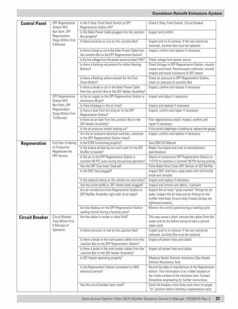
Donaldson Retrofit Emissions System
Control Panel DPF Regeneration Station Will Not Start, DPF Regeneration Stops Within First 5 Minutes
Is the E-Stop, Front Panel Switch or DPF Regeneration Station Off?
Check E-Stop, Front Switch, Circuit Breaker
Is the Main Power Cable plugged into the Junction Box properly?
Inspect and confirm
Is there corrosion or rust on the Junction Box? Inspect and try to remove. If the rust cannot be removed, Junction Box must be replaced.
Is there a break or cut in the Main Power Cable from the Junction Box to the DPF Regeneration Station?
Inspect, confirm and replace if necessary
Is the line voltage from the power source at least 210V? Check voltage from power sourceIs there a flashing red present for either Heating Buttons?
Check Voltage to DPF Regeneration Station, visually inspect and check Thermocouple continuity, visually inspect and check resistance of SEF Heater
Is there a flashing yellow present for the Cool Down Button?
Check air pressure to DPF Regeneration Station, check air pressure to Junction Box
Is there a break or cut in the Main Power Cable from the Junction Box to the SEF Heater Assembly?
Inspect, confirm and replace if necessary
DPF Regeneration Station Will Not Start, DPF Regeneration Stops Within First 15 Minutes
Is the air supply to the DPF Regeneration Station a continuous 90 psi?
Inspect and adjust if necessary
Is there blockage in the air lines? Inspect and replace if necessaryIs there a leak from the shop air to the DPF Regeneration Station?
Inspect, confirm and repair if necessary
Is there an air leak from the Junction Box to the SEF Heater Assembly?
Poor regenerations result. Inspect, confirm and repair if necessary
Is the air pressure switch leaking air? If the switch diaphragm is leaking air, replace the gaugeAre the air pressure electrical switches, solenoids in the DPF Regeneration Station intact?
Inspect, confirm and replace if necessary
Regeneration End User is Having to Frequently Regenerate the DPF Section
Is the EDM functioning properly? See EDM I/O ManualIs the engine producing too much soot for the SEF Muffler to handle?
Repair the engine and tune to manufacturers specifications
Is the air to the DPF Regeneration Station a constant 90 PSI, even during the pulsing operation?
Adjust air pressure to DPF Regeneration Station to 110 PSI to maintain a constant 90 PSI during pulsing
Has the DPF Core been Cleaned? Pulse-Bake-Pulse Clean DPF Section of SEF MufflerIs the DOC face plugged? Inspect DOC inlet face, wipe clean with soft bristle
brush and reinstallIs the exhaust tubing on the vehicle too restrictive? Inspect and replace if necessaryHas the outlet baffle or SEF Heater been clogged? Inspect and remove any debris, if presentAre air connections from Regeneration Station to SEF Muffler Assembly tight with no air leaks?
Inspect the air hose “quick connect” fittings for air leaks. Inspect the air hose and air fittings on the muffler inlet body. Ensure body V-band clamps are tightened properly.
Are the displays on the DPF Regeneration Station reading normal during a heating cycle?
Monitor the control panel during a heating cycle
Circuit Breaker Circuit Breaker Trips Within First 5 Minutes of Operation
Are the cables in water or other fluid? This may cause a short, remove the cables from the water and let dry before trying to start a second regen cycle
Is there corrosion or rust on the Junction Box? Inspect and try to remove. If the rust cannot be removed, Junction Box must be replaced
Is there a break in the main power cables from the Junction Box to the DPF Regeneration Station?
Inspect all power lines and cables
Is there a break in the main power cables from the Junction Box to the SEF Heater Assembly?
Inspect all power lines and cables
Is SEF Heater operating properly? Measure Heater Element resistance (See Heater Element Resistance Test)
Is the Regeneration Station connected to 240V electrical service?
Record the date of manufacture of the Regeneration station. This information is on a label located on the inside surface of the enclosure door. Contact Donaldson engineering for further instructions.
Has the circuit breaker been reset? Cycle the breaker a few times and return to proper “on” position before starting a regeneration cycle
24 Semi-Active Electric Filter (SEF) Muffler Systems Owner’s Manual - P232575 Rev 2
Donaldson Retrofit Emissions System
Swapping and Re-designation
Before You BeginMoving any component of a verified device from one vehicle/engine to another is subject to regulatory compliance requirements. “Swapping” is the exchange of an existing DECS subcomponent with an identical subcomponent. “Re-designation” is the movement of an entire DECS from one vehicle/engine to another and is also subject to regulatory compliance requirements. Specific requirements for “swapping” and “re-designation” are found within the rules and regulations of the California “Verification Procedure, Warranty and In-Use Compliance Requirements for In-Use Strategies to Control Emissions from Diesel Engines”.
Before “swapping” a SEF device component or accomplishing “re-designation” of the entire device, conduct the following:
• Review the Donaldson Company “Swapping and Re-designation Policy” provided on the California Air Resources Board website for the Diesel Emission Control Strategy (DECS) device considered for swapping or re-designation. All terms and conditions of the policy must be met. Failure to meet all of the terms and conditions of the policy may result in a non-compliance condition and/or may void the warranty of the device.
• Review the most current Executive Order available on the ARB website for the device considered for swapping or re-designation. Any and all actions taken to accomplish swapping or re-designation must ensure that all terms and conditions of the DECS device Executive Order are met.
• All other applicable Donaldson Company Policies and Procedures for “Swapping and Re designation” of devices must be followed. Contact Donaldson Company (or your Authorized Dealer) for instructions to accomplish proper swapping or re-designation of a DECS device.
• Note: Certain information reporting and recordkeeping is required by regulatory agencies for compliance. Failure to track and report swapping or re-designation activity information may result in non-compliance. Follow all Donaldson requirements for tracking and information reporting.
• Download the EDM data and plot the log file data. Donaldson Engineering can assist in interpreting this log file to determine if the filter is subject to an engine upset condition or a valid swapping candidate.
In addition, this manual contains certain instructions and
requirements to support “Swapping and Re designation” for SEF devices.
Instructions for Assessing The System or DPF Section Still Meets Its Verified Emissions Reductions (PM)The procedure outlined below is valid for testing a core or entire SEF System.
1. Download and inspect the EDM log file data. Review the SEF system backpressure/temperature data to ensure the device has been operating properly.
2. Complete a Donaldson Pre-Assessment on the suspect engine/application.
Component SwappingFor the instructions that follow the DPF Section on the vehicle/engine before the start of swapping activity will be referred to as “core A”. The DPF Section to be temporarily exchanged with core A and installed on the vehicle/engine will be referred to as “core B”. Note - core B must be a DPF section dedicated to swapping activity over its entire useful life.
System components approved for swapping:• SEF System DPF Section
Note: Donaldson allows only temporary swapping of the DPF Section and then ONLY for the purpose of providing routine cleaning service of the DPF Section originally installed on the vehicle/engine (i.e. core A). The engine/vehicle participating in swapping of the DPF Section must be operating properly and in a good state of maintenance. Swapping a DPF Section for the purpose of engine troubleshooting is not permitted since a malfunctioning engine may damage the DPF Section.
Confirmation Process To Ensure the Appropriate Core is Used for Swapping1. Confirm whether core A is from a SEF System. Core B
must be of the same DECS number. You may confirm the appropriate DECS number by referencing the most current verification listed on the ARB website. The DECS number can be found on either the device or engine tag. Reference the SEF Muffler IOM for further information.
2. Confirm that the Engine Family Name is listed in Attachment 1 of the applicable SEF Executive Order as determined in Step 1 above. The engine family name must be listed in the Executive Order of the technology to proceed.
Semi-Active Electric Filter (SEF) Muffler Systems Owner’s Manual - P232575 Rev 2 25
Donaldson Retrofit Emissions System
3. Obtain an appropriate DPF Section to install on the vehicle/engine as core B. Core B must have the same DECS number as Core A (SEF) as described in Step 1.
a) Core B must be a DPF section dedicated to swapping activity over its entire useful life. Core B must be cleaned per Donaldson cleaning requirements every 200 to 300 hours of operation, or when EDM backpressure warnings indicate service is required, whichever comes first. (See “DPF Section Cleaning Method & Process” contained in the “Maintenance and Service” Section of this manual.)
b) Core B must be the same physical size as core A in both length and diameter and with the same flange connection.
Installation and Re-installation Practices
Failure to follow these instructions may result in a non-compliant system installation, damage to the SEF System, and/or may void the warranty of the system.
4. Remove core A from the vehicle/engine. Follow removal steps of the “Procedure to Remove/Install DPF Section for Cleaning” contained in the “Maintenance and Service” Section of this manual.
a) Core A must be cleaned per the “DPF Section Cleaning Method & Process” contained in the “Maintenance and Service” Section of this manual, and then reinstalled only on the vehicle/engine from which it came.
5. Install core B on the vehicle/engine. Follow installation steps of the “Procedure to Remove/Install DPF Section for Cleaning” contained in the “Maintenance and Service” section of this manual.
6. Return the vehicle to service (if required) for no longer than 30 days of operation then remove core B and reinstall core A. Follow installation steps of the “Procedure to Remove/Install DPF Section for Cleaning” contained in the “Maintenance and Service” section of this manual.
7. Record all cleaning, vehicle, engine, and device swapping information and report as required. Failure to report the required information may result a non-compliant system installation, or may void the warranty of the system.
System Re-designationFor the instructions that follow the vehicle/engine from which the SEF System will be removed will be referred to as the “donor vehicle/engine”. The vehicle/engine to receive the SEF System from the donor vehicle/engine will be referred to as the “recipient vehicle/engine”.
Re-designation of a SEF System from a donor vehicle is treated as a new application with regard to the recipient vehicle/engine. Application of the SEF System to the recipient vehicle/engine must meet all terms and conditions of the applicable Executive Order and Donaldson pre-assessment processes.
Failure to follow this procedure may result in a non-compliant system installation and/or may void the warranty of the system.
System components approved for re-designation:
• SEF Muffler Assembly. The Muffler Assembly consists of an Inlet section, DOC section, heater section, DPF section, and outlet section. See SEF Muffler section of this manual.
System components not approved for re-designation:
• Emissions Device Monitor (EDM). A new EDM or re-flashed SECM/MM must be installed when a SEF system is Re-designed.
Confirmation Process to Ensure the Appropriate SEF Muffler is used for Re-designation
1. Confirm whether the DECS system is from a SEF System. The recipient vehicle/engine must be approved for the particular DECS system. You may confirm the appropriate DECS and approved engine family numbers by referencing the most current verification listed on the ARB website. The DECS number can be found on either the engine or device tag. Please see the SEF IOM for more information.
2. The SEF System to be re-designated must be less than 10 years old.
a) Determine the date of manufacture by the MM-YY date code on the DPF Core Assembly where “MM” is a 2 digit number representing the month of manufacture, and “YY” is a 2 digit number representing the year of manufacture. If the date code indicates a device age of 10 years or greater the system cannot be re-designated.
b) If a date code is not present or visible then contact Donaldson with the serial number of the device to determine the original manufacturing date and age of the device.
26 Semi-Active Electric Filter (SEF) Muffler Systems Owner’s Manual - P232575 Rev 2
Donaldson Retrofit Emissions System
c) If the age of the device cannot be determined it cannot be re-designated.
3. Confirm that the Engine Family Name is listed in Attachment 1 of the applicable SEF Executive Order as determined in Step 1 above. The engine family name must be listed in the Executive Order of the technology to proceed.
4. The recipient vehicle/engine must meet all the requirements of the Executive Order and Donaldson’s pre-assessment process to proceed.
a) The owner must receive an approval letter from Donaldson in order to proceed with the order and re-designation process.
Installation and Re-installation Practices
Failure to follow these instructions may result in a non-compliant system installation, damage to the SEF System, and/or may void the warranty of the system.
1. Determine system installation requirements of the recipient vehicle/engine and obtain all system components and hardware required to install the SEF System on the recipient vehicle/engine. Contact your Donaldson Dealer for assistance. Components must include, but are not limited to:
a) A new Emissions Device Monitor (EDM) or re-flashed SECM/MM is required for the recipient vehicle/engine.
b) Replace all V-band clamps on the Muffler Assembly coming from the donor vehicle/engine.
c) A new replacement device label and new replacement engine label is required. (Available from Donaldson)
2. Remove the SEF Muffler Assembly from the donor vehicle/engine.
3. Remove the SEF System engine label from the donor vehicle/engine.
a) This label must be destroyed by cutting into pieces no larger than ½ inch by 2 inches.
b) If the donor vehicle/engine will be returned to service it must first be made compliant with all applicable rules and regulations for emission control. This may include installing a new Retrofit device or returning the vehicle/engine exhaust system to its original certified configuration. Contact your local regulatory agency for appropriate remedies.
4. The DPF Section from the donor vehicle/engine must be cleaned per Donaldson Company requirements and specifications prior to installation of the Muffler assembly on the recipient vehicle/engine. (See “DPF Section Cleaning Method & Process”) contained in the “Maintenance and Service” section of this manual.
5. Follow all requirements and procedures of this manual to install the Muffler Assembly and EDM kit on the recipient vehicle/engine.
a) Remove label from the DPF Core Assembly and attach a new replacement label obtained in step 1c). Spot weld the new tag to the DPF Section in the same location where the original DECS tag was removed from. Ensure a secure tack weld on all four corners.
b) Install the engine label per this manual.
6. Record all vehicle, engine, and device re-designation information and report as required. Failure to report the required information may result a non-compliant system installation.
7. Return the recipient vehicle/engine to service.
Swapping and Re-designation Warranty
Per California Code of Regulations (CCR) Title 13.Division 3.Chapter 14.Section 2707, the manufacturer will honor the original installation warranty and warranty period.
If the installer of either a swapped component or re-designated diesel emission control strategy is not the same as the installer who did the original installation of the diesel emission control strategy, the new installer must assume the installation warranty responsibilities defined in section 2707 for the remainder of the original warranty period or until another installer swaps the component or re-designates the diesel emission control strategy. If the original installation warranty has expired or has less than one year remaining, the installer must issue a new warranty to guard against potential installation defects. The new installation warranty must meet the requirements of section 2707 except that the minimum period is reduced to one year from the date of installation. Any transfer of a diesel emission control strategy or component by an installer that does not offer this installation warranty is not considered a valid installation.
Semi-Active Electric Filter (SEF) Muffler Systems Owner’s Manual - P232575 Rev 2 27
Donaldson Retrofit Emissions System
SEF Muffler System Limited Warranty
Your Warranty Rights and Obligations
Donaldson must warrant the diesel emission control system in the application for which it is sold or leased to be free from defects in design, materials, workmanship, or operation of the diesel emission control system which cause the diesel emission control system to fail to conform to the emission control performance level it was verified to, or to the requirements in the California Code of Regulations, Title 13, Sections 2700 to 2706, and 2710, for the periods of time listed below, provided there has been no abuse, neglect, or improper maintenance of your diesel emission control system, vehicle or equipment, as specified in the owner’s manuals. Where a warrantable condition exists, this warranty also covers the engine from damage caused by the diesel emission control system, subject to the same exclusions for abuse, neglect or improper maintenance of your vehicle or equipment. Please review your owner’s manual for other warranty information. Your diesel emission control system may include a core part (e.g., particulate filter, diesel oxidation catalyst, selective catalytic reduction converter) as well as hoses, connectors, a back pressure monitor (if applicable), and other emission-related assemblies. Where a warrantable condition exists, Donaldson will repair or replace your diesel emission control system at no cost to you including diagnosis, parts, and labor.
Warranty Coverage
Warranty coverage for the SEF Muffler System (SEF Muffler, EDM and DPF Regeneration Station) begins on the date and mileage when the first SEF Muffler is installed by the user and expires when the specified number of years or miles has passed, whichever occurs first.
• Medium Heavy-Duty 5 years or 100,000 miles (170-250 hp / GVWR from 19,500-33,000 lbs.)
• Heavy Heavy-Duty 5 years or 150,000 miles (Exceeds 250 hp / GVWR exceeds 33,000 lbs.)
• Heavy Heavy-Duty 2 years, unlimited miles (Exceeds 250 hp / GVWR exceeds 33,000 lbs. and the truck is 1. typically driven over 100,000 miles per year and, 2. has less than 300,000 miles on the odometer at the time of installation.)
If any emission-related part of your diesel emission control system is defective in design, materials, workmanship, or operation of the diesel emission control system thus causing the diesel emission control system to fail to conform to the
emission control performance level it was verified to, or to the requirements in the California Code of Regulations, Title 13, Sections 2700 to 2706, and 2710, within the warranty period, as defined above, Donaldson will repair or replace the diesel emission control system, including parts and labor.
In addition, Donaldson will replace or repair the engine components to the condition they were in prior to the failure, including parts and labor, for damage to the engine proximately caused by the verified diesel emission control strategy. This also includes those relevant diagnostic expenses in the case in which a warranty claim is valid. Donaldson may, at its option, instead pay the fair market value of the engine prior to the time the failure occurs.
Owners Warranty Responsibility
As the (vehicle, engine, equipment) owner, you are responsible for performing the required maintenance described in your owner’s manual. Donaldson recommends that you retain all maintenance records and receipts for maintenance expenses for your vehicle, engine, or equipment, and diesel emissions control system. If you do not keep your receipts or fail to perform all scheduled maintenance, Donaldson may have grounds to deny warranty coverage. You are responsible for presenting your vehicle, equipment or engine, and diesel emissions control system to a Donaldson dealer as soon as a problem is detected. The warranty repair or replacement should be completed in a reasonable amount of time, not to exceed 30 days. If a replacement is needed, this may be extended to 90 days should a replacement not be available, but must be performed as soon as a replacement becomes available.
If you have any questions regarding your warranty rights and responsibilities, you should contact Donaldson Emissions Retrofit Technical Support toll-free at (866) 817-8733, or the California Air Resources Board at 9528 Telestar Avenue, El Monte, California 91731, or (800) 363-7663, or electronic mail: [email protected].
Installation Warranty Responsibility
The Donaldson authorized installer must furnish the owner with a copy of the following statement.
Donaldson Retrofit Emissions System
Technical Support [email protected]
© 2013 Donaldson Company, Inc. IOM P232575, Rev 2All rights reserved. Printed in USA June 2013
Donaldson Company, Inc.Minneapolis, MNwww.donaldsonexhaust.com
Your Warranty Rights and Obligations
__________________________________(Installer’s name) warrants that the installation of a diesel emission control system is free from defects in workmanship or materials which cause the diesel emission control system to fail to conform to the emission control performance level it was verified to, or to the requirements in the California Code of Regulations, Title 13, Sections 2700 to 2706. The warranty period and the extent of the warranty coverage provided by the installer must be the same as the warranty provided by the product manufacturer, and the same exclusions must apply.
Owner’s Warranty Responsibility
As the vehicle, engine, or equipment owner, you are responsible for presenting your vehicle, engine, or equipment, and diesel emission control system to your Donaldson installer as soon as a problem with the installation is detected. If you have questions regarding your warranty rights and responsibilities, you should contact ___________________________________________________(installer’s contact) at _______________________ (installers toll-free phone) or the California Air Resources Board at 9528 Telstar Avenue, El Monte, California 91731, or (800) 363-7664, or electronic mail: [email protected].
Actions and Improper Maintenance That May Result in Denial of Your Warranty Coverage
The following conditions are considered to be abuse, neglect or improper maintenance that may void your warranty:
• Failure to follow Original Equipment Manufacturer (OEM) maintenance and operating procedures. Proper OEM maintenance and operating procedures are understood to be those procedures recommended by the OEM to ensure engine longevity and operation.
• Excessive particulate emissions due to poor engine operation and maintenance.
• Misapplication to an engine model or to a duty cycle other than that which it is designed and approved.
• Improper installation (strict adherence to the Donaldson owners manual is required).
• Alterations or attempted repairs.• Progressive engine failure that allows lube oil, fuel
or coolant to be present in the engine exhaust, in excess of OEM specifications.
• Use of fuel: (a) other than that for which the engine is calibrated or
other than recommended by Donaldson. (b) containing other than ultra low sulfur diesel or not
approved in writing by Donaldson, or fuel other than that which is specifically required to achieve the emissions required.
(c) blended fuel with lube oil, kerosene, fuel additives or other materials not approved in writing by Donaldson.
• Excessive lube oil consumption.• Physical damage caused by misuse, abuse or road
hazards including (but not limited to) dents, cuts or fractures.
• Damage caused by improper cleaning procedures (failure to adhere to Donaldson recommended cleaning guidelines).
• Failures or damage caused by mounting system failures.• Damage to the DPF Section or plugging caused by water
entry.