Embed Size (px)
Citation preview
Document 27/600; Release EN03 2014-09-19
Manual
I/O-modules for PCD1 / PCD2 series
and for PCD3 series
Saia-Burgess Controls AG
Manual I/O-modules for PCD1 | PCD2 series Document 27/600; Release EN03 2014-09-19 0-1
Content
0
Content
0 Content0 Content0.1 Document versions ............................................................................... 0-40.3 Brands and trademarks ........................................................................ 0-4
5 Input/output (I/O) modules for PCD1 and PCD25.1 General informations ............................................................................. 5-15.1.1 Overview ............................................................................................... 5-15.1.2 Outphased I/O-moduels PCD2 ............................................................ 5-65.1.3 Power consumption of PCD2 input/output modules .............................. 5-85.1.4 Maximal current consumption from base units ...................................... 5-8
5.2 Digital input modules ............................................................................. 5-95.2.1 PCD2.E11x, 8 digital inputs ................................................................... 5-105.2.2 PCD2.E160/161, 16 digital inputs, ribbon cable connector ................... 5-135.2.3 PCD2.E165/166, 16 digital inputs, spring terminal connectors ............. 5-16
5.3 Digital input modules, electrically isolated ............................................. 5-185.3.1 PCD2.E500, 6 digital inputs for 115 - 230 VAC .............................................. 5-195.3.2 PCD2.E61x, 8 digital inputs, electrically isolated .................................. 5-21
5.4 Digital output modules ........................................................................... 5-235.4.1 PCD2.A300, 6 digital outputs for 2 A each ............................................ 5-245.4.2 PCD2.A400, 8 digital outputs for 0.5 A each ......................................... 5-265.4.3 PCD2.A460, 16 digital outputs for 0.5 A each, with ribbon connector ... 5-285.4.4 PCD2.A465, 16 digital outputs, for 0.5 A each ...................................... 5-31
5.5 Digital output modules, electrically isolated .......................................... 5-335.5.1 PCD2.A200, 4 relays with make contacts, with contact protection ....... 5-345.5.2 PCD2.A210, 4 relays with break contacts, with contact protection ....... 5-365.5.3 PCD2.A220, 6 relays with make contacts, without contact protection .. 5-385.5.4 PCD2.A250, 8 relays with make contacts, without contact protection .. 5-405.5.5 PCD2.A410, 8 digital outputs for 0.5 A each, electrically isolated ......... 5-42
5.6 Digital combined input and output modules .......................................... 5-445.6.1 PCD2.B100, 2 inputs + 2 outputs
+ 4 digital inputs/outputs (selectable) .................................................... 5-455.7 Multi-functional input/output modules .................................................... 5-485.7.1 PCD2.G400, multi-functional input/output module ................................ 5-495.7.2 PCD2.G410, multi-functional I/O module
with elect. isolated digital I/O ................................................................. 5-505.8 Analogue input modules ........................................................................ 5-525.8.1 PCD2.W10x, analogue inputs, 4 channels, 12 bit resolution ................ 5-535.8.2 PCD2.W11x, analogue inputs, 4 channels, 12 bit resolution ................ 5-565.8.3 PCD2.W2x0, analogue inputs, 8 channels, 10 bit resolution ................ 5-615.8.4 PCD2.W3x0, analogue inputs, 8 channels, 12 bit resolution ................ 5-67
5.9 Analogue input modules with electricaly isolation ................................. 5-735.9.1 PCD2.W3x5, analogue inputs, 7 channels, 12 bit resolution,
electrical isolated ................................................................................... 5-745.10 Analogue output modules ..................................................................... 5-785.10.1 PCD2.W4x0, analogue outputs, 4 channels, 8 bit resolution ................ 5-795.10.2 PCD2.W6x0, analogue outputs, 4 channels, 12 bit resolution .............. 5-83
5.11 Analogue output modules with electrically isolation .............................. 5-875.11.1 PCD2.W6x5, analogue outputs, 6 (4) channels,
10 bit resolution, electrcal isolated ........................................................ 5-885.12 Analogue input and output modules ...................................................... 5-92
Saia-Burgess Controls AG
Manual I/O-modules for PCD1 | PCD2 series Document 27/600; Release EN03 2014-09-19 0-2
Content
0
Content
5.12.1 PCD2.W5x0, analogue inputs/outputs, 2 + 2 channels, 12 bit resolution ..................................................................................... 5-93
5.13 Combined analogue input/output modules with galvanic isolation ........ 5-975.13.1 PCD2.W525 Combined analogue input/output modules
with galvanic isolation ........................................................................... 5-985.14 Analogue weighing modules ................................................................. 5-1065.15 Analogue thermocouple modules .......................................................... 5-1075.16 Fast counting modules .......................................................................... 5-1085.16.1 PCD2.H100, counting module up to 20 kHz ......................................... 5-1095.16.2 PCD2.H110, general purpose counting / measuring module
up to 100 kHz ........................................................................................ 5-1145.17 SSI interface modules ........................................................................... 5-1165.17.1 PCD2.H150, SSI interface module for absolute encoder ...................... 5-117
5.18 Motion control modules for stepper motors ........................................... 5-1205.18.1 PCD2.H210, Motion control module for stepper motors ....................... 5-121
5.19 Motion control modules for servo-motors .............................................. 5-1245.19.1 PCD2.H31x, motion control module for servo-motors, 1-axis encoder . 5-1255.19.2 PCD2.H32x, motion control modules for servo-drives .......................... 5-129
6 Input/output (I/O) modules for PCD36.1 Introduction to I/O modules ................................................................... 6-16.1.1 Connector types .................................................................................... 6-46.1.2 Current consumption of the modules .................................................... 6-56.1.3 External input voltage ............................................................................ 6-66.1.4 Example I/O modules ............................................................................ 6-76.1.5 Open the module housing ..................................................................... 6-76.1.6 Outphased I/O-moduels PCD2 ............................................................ 6-8
6.2 Digital input modules ............................................................................. 6-106.2.1 PCD3.E110/111/112/116, 8 digital inputs ............................................... 6-116.2.2 PCD3.E160/161, 16 digital inputs, ribbon cable connector ................... 6-136.2.3 PCD3.E165/166, 16 digital inputs, cage clamp terminal connectors .... 6-15
6.3 Digital input modules, electrically isolated from the I/O Bus ................. 6-176.3.1 PCD3.E500, 6 digital inputs, electrically isolated from the I/O Bus ....... 6-186.3.2 PCD3.E610/613, 8 digital inputs, electrically isolated from the I/O Bus 6-20
6.4 Digital output modules .......................................................................... 6-226.4.1 PCD3.A300, 6 digital outputs for 2 A each ............................................ 6-236.4.2 PCD3.A400, 8 digital outputs for 0.5 A each ......................................... 6-256.4.3 PCD3.A460, 16 digital outputs for 0.5 A each,
with ribbon cable connector .................................................................. 6-276.4.4 PCD3.A465, 16 digital outputs for 0.5 A each ....................................... 6-29
6.5 Digital output modules, electrically isolated ......................................... 6-316.5.1 PCD3.A200, 4 relays with make contacts, with contact protection ....... 6-326.5.2 PCD3.A210, 4 relays with break contacts, with contact protection ....... 6-346.5.3 PCD3.A220, 6 relays with make contacts, without contact protection .. 6-366.5.4 PCD3.A251, 8 relays, 6 with changeover contacts,
2 with make contacts ............................................................................. 6-386.5.5 PCD3.A410, 8 digital outputs for 0.5 A each, electrically isolated ......... 6-40
Saia-Burgess Controls AG
Manual I/O-modules for PCD1 | PCD2 series Document 27/600; Release EN03 2014-09-19 0-3
Content
0
Content
6.6 Digital output modules for manual operation, electrically isolated ....... 6-426.6.1 PCD3.A810, Digital manual control module with 4 relays,
2 with changeover, 2 with make contacts .............................................. 6-436.6.2 PCD3.A860, digital light and shade module, with 2 make contacts ...... 6-47
6.7 Digital combined input/output modules ................................................. 6-536.7.1 PCD3.B100, combined with 2 inputs + 4 digital I/Os ............................. 6-54
6.8 Analogue input modules ........................................................................ 6-576.8.1 PCD3.W2x0, analogue inputs, 8 channels, 10 bit resolution ................ 6-586.8.2 PCD3.W3x0, analogue inputs, 8 channels, 12 bit resolution ................ 6-64
6.9 Analogue input modules, electrically isolated from the I/O Bus ........... 6-726.9.1 PCD3.W3x5, analogue inputs electrically isolated from the I/O Bus,
7 channels, 12 Bit resolution ................................................................. 6-736.10 Analogue output modules .................................................................... 6-776.10.1 PCD3.W4x0, analogue outputs, 4 channels, 8 bit resolution ................ 6-786.10.2 PCD3.W6x0, analogue outputs, 4 channels, 12 bit resolution .............. 6-82
6.11 Analogue output modules, electrically isolated from the I/O Bus ......... 6-876.11.1 PCD3.W6x5, analogue outputs electrically isolated from the I/O Bus,
6(4) channels, 10 Bit resolution ............................................................. 6-886.12 Analogue combined input/output modules ............................................ 6-926.12.1 PCD3.W500, analogue inputs/outputs, 2 + 2 channels,
12 bit resolution ..................................................................................... 6-936.13 Analogue combined input/output modules, electrically isolated ............ 6-976.13.1 PCD3.W525 analogue combined input/output module
with electrical isolation .......................................................................... 6-986.14 Analogue manual control modules ....................................................... 6-1036.14.1 PCD3.W800, Analogue manual control module with 4 output channels,
0…+10 V, 10 bit resolution .................................................................... 6-1046.15 Weighing modules ................................................................................. 6-1086.15.1 PCD3.W720 .......................................................................................... 6-108
6.16 General-purpose temperature modules ................................................ 6-1096.16.1 PCD3.W745 .......................................................................................... 6-109
6.17 Counting and motion control I/O modules ............................................. 6-1106.17.1 PCD3.H100, counting module up to 20 kHz ......................................... 6-1116.17.2 PCD3.H110, counting module up to 100 kHz ........................................ 6-1166.17.3 PCD3.H150, SSI interface module for absolute encoder ...................... 6-1186.17.4 PCD3.H210, Motion control module for stepper motors ....................... 6-1216.17.5 PCD3.H31x, motion control module for servo-motors, 1-axis encoder . 6-124
6.18 Miscellaneous modules ......................................................................... 6-1286.18.1 PCD3.S100 Workshop simulator unit .................................................... 6-129
A AppendixA.1 Icons ...................................................................................................... A-1A.4 Installation direction and relays contact protection ............................... A-2A.4.1 Installation direction for switching low voltages ..................................... A-2A.4.2 Installation direction for switching higher voltages ................................ A-2A.4.3 Switching inductive loads ...................................................................... A-4A.4.4 Relay manufacturer’s information on RC unit dimensioning ................. A-4
A.6 Contact .................................................................................................. A-6
Saia-Burgess Controls AG
Manual I/O-modules for PCD1 | PCD2 series Document 27/600; Release EN03 2014-09-19 0-4
Content
0
Document versions | Brands and trademarks
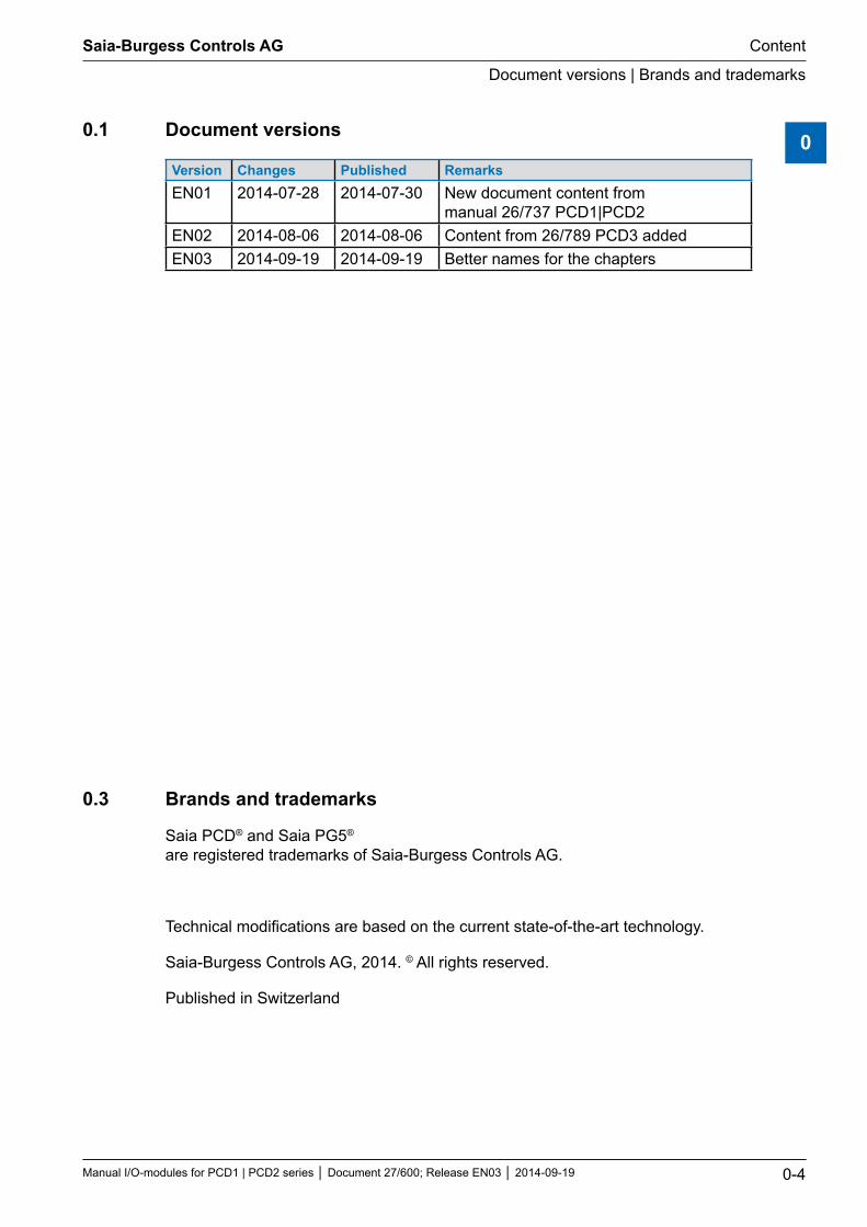
0.1 Document versions
Version Changes Published RemarksEN01 2014-07-28 2014-07-30 New document content from
manual 26/737 PCD1|PCD2EN02 2014-08-06 2014-08-06 Content from 26/789 PCD3 addedEN03 2014-09-19 2014-09-19 Better names for the chapters
0.3 Brands and trademarks
Saia PCD® and Saia PG5® are registered trademarks of Saia-Burgess Controls AG.
Technical modifications are based on the current state-of-the-art technology.
Saia-Burgess Controls AG, 2014. © All rights reserved.
Published in Switzerland
Saia-Burgess Controls AG
Manual I/O-modules for PCD1 | PCD2 series Document 27/600; Release EN03 2014-09-19 5-1
I/O modules PCD1|PCD2
Overview
5
5 Input/output (I/O) modules for PCD1 and PCD2
5.1 General informations
5.1.1 Overview
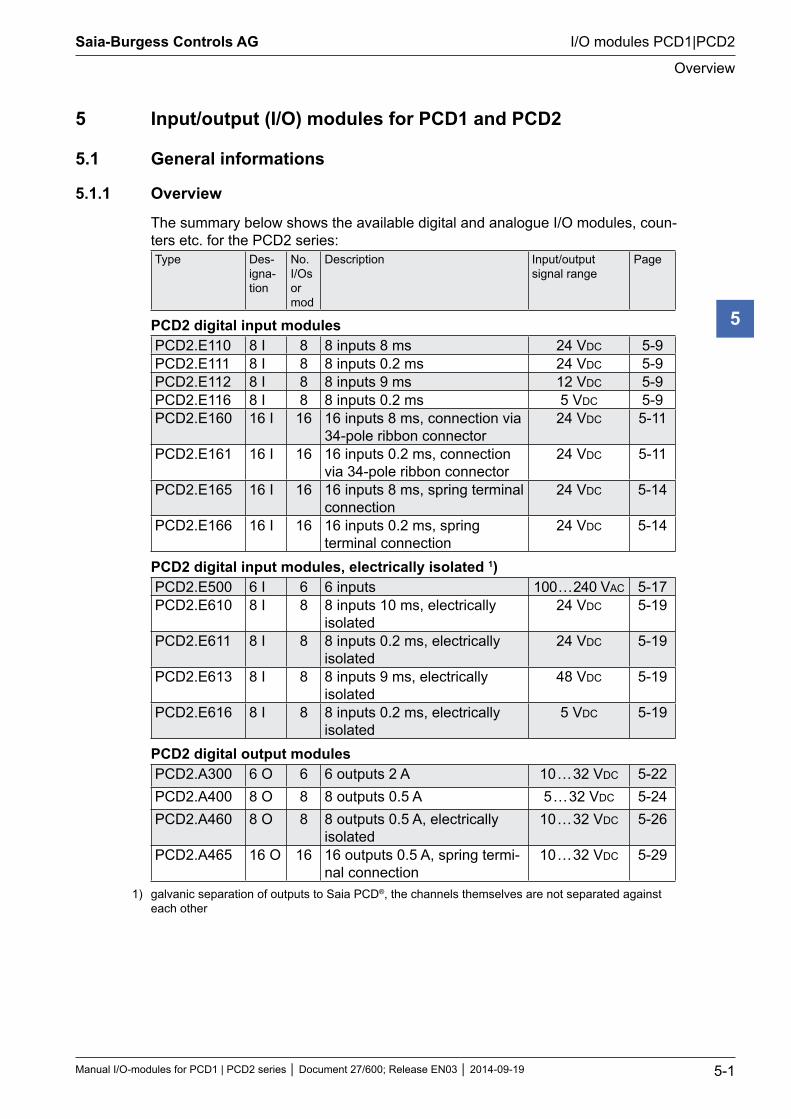
The summary below shows the available digital and analogue I/O modules, coun-ters etc. for the PCD2 series:Type Des-
igna-tion
No. I/Os or mod
Description Input/output signal range
Page
PCD2 digital input modulesPCD2.E110 8 I 8 8 inputs 8 ms 24 VDC 5-9PCD2.E111 8 I 8 8 inputs 0.2 ms 24 VDC 5-9PCD2.E112 8 I 8 8 inputs 9 ms 12 VDC 5-9PCD2.E116 8 I 8 8 inputs 0.2 ms 5 VDC 5-9PCD2.E160 16 I 16 16 inputs 8 ms, connection via
34-pole ribbon connector24 VDC 5-11
PCD2.E161 16 I 16 16 inputs 0.2 ms, connection via 34-pole ribbon connector
24 VDC 5-11
PCD2.E165 16 I 16 16 inputs 8 ms, spring terminal connection
24 VDC 5-14
PCD2.E166 16 I 16 16 inputs 0.2 ms, spring terminal connection
24 VDC 5-14
PCD2 digital input modules, electrically isolated 1) PCD2.E500 6 I 6 6 inputs 100 … 240 VAC 5-17PCD2.E610 8 I 8 8 inputs 10 ms, electrically
isolated24 VDC 5-19
PCD2.E611 8 I 8 8 inputs 0.2 ms, electrically isolated
24 VDC 5-19
PCD2.E613 8 I 8 8 inputs 9 ms, electrically isolated
48 VDC 5-19
PCD2.E616 8 I 8 8 inputs 0.2 ms, electrically isolated
5 VDC 5-19
PCD2 digital output modulesPCD2.A300 6 O 6 6 outputs 2 A 10 … 32 VDC 5-22PCD2.A400 8 O 8 8 outputs 0.5 A 5 … 32 VDC 5-24PCD2.A460 8 O 8 8 outputs 0.5 A, electrically
isolated10 … 32 VDC 5-26
PCD2.A465 16 O 16 16 outputs 0.5 A, spring termi-nal connection
10 … 32 VDC 5-29
1) galvanic separation of outputs to Saia PCD®, the channels themselves are not separated against each other
Saia-Burgess Controls AG
Manual I/O-modules for PCD1 | PCD2 series Document 27/600; Release EN03 2014-09-19 5-2
I/O modules PCD1|PCD2
Overview
5
Type Des-igna-tion
No. I/Os or mod
Description Input/output signal range
Page
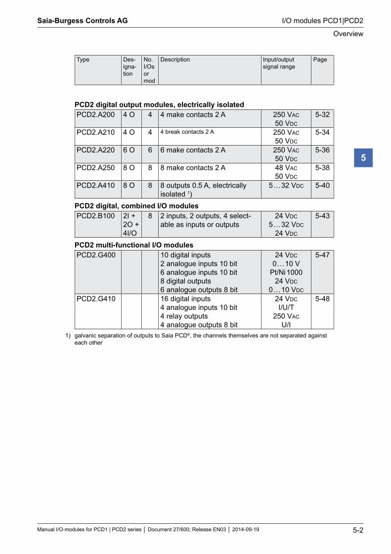
PCD2 digital output modules, electrically isolatedPCD2.A200 4 O 4 4 make contacts 2 A 250 VAC
50 VDC5-32
PCD2.A210 4 O 4 4 break contacts 2 A 250 VAC 50 VDC
5-34
PCD2.A220 6 O 6 6 make contacts 2 A 250 VAC 50 VDC
5-36
PCD2.A250 8 O 8 8 make contacts 2 A 48 VAC 50 VDC
5-38
PCD2.A410 8 O 8 8 outputs 0.5 A, electrically isolated 1)
5 … 32 VDC 5-40
PCD2 digital, combined I/O modulesPCD2.B100 2I +
2O + 4I/O
8 2 inputs, 2 outputs, 4 select-able as inputs or outputs
24 VDC 5 … 32 VDC
24 VDC
5-43
PCD2 multi-functional I/O modulesPCD2.G400 10 digital inputs
2 analogue inputs 10 bit 6 analogue inputs 10 bit 8 digital outputs 6 analogue outputs 8 bit
24 VDC 0 … 10 V
Pt/Ni 1000 24 VDC
0 … 10 VDC
5-47
PCD2.G410 16 digital inputs 4 analogue inputs 10 bit 4 relay outputs 4 analogue outputs 8 bit
24 VDC I/U/T
250 VAC U/I
5-48
1) galvanic separation of outputs to Saia PCD®, the channels themselves are not separated against each other
Saia-Burgess Controls AG
Manual I/O-modules for PCD1 | PCD2 series Document 27/600; Release EN03 2014-09-19 5-3
I/O modules PCD1|PCD2
Overview
5
Type Des-igna-tion
No. I/Os or mod
Description Input/output signal range
Page
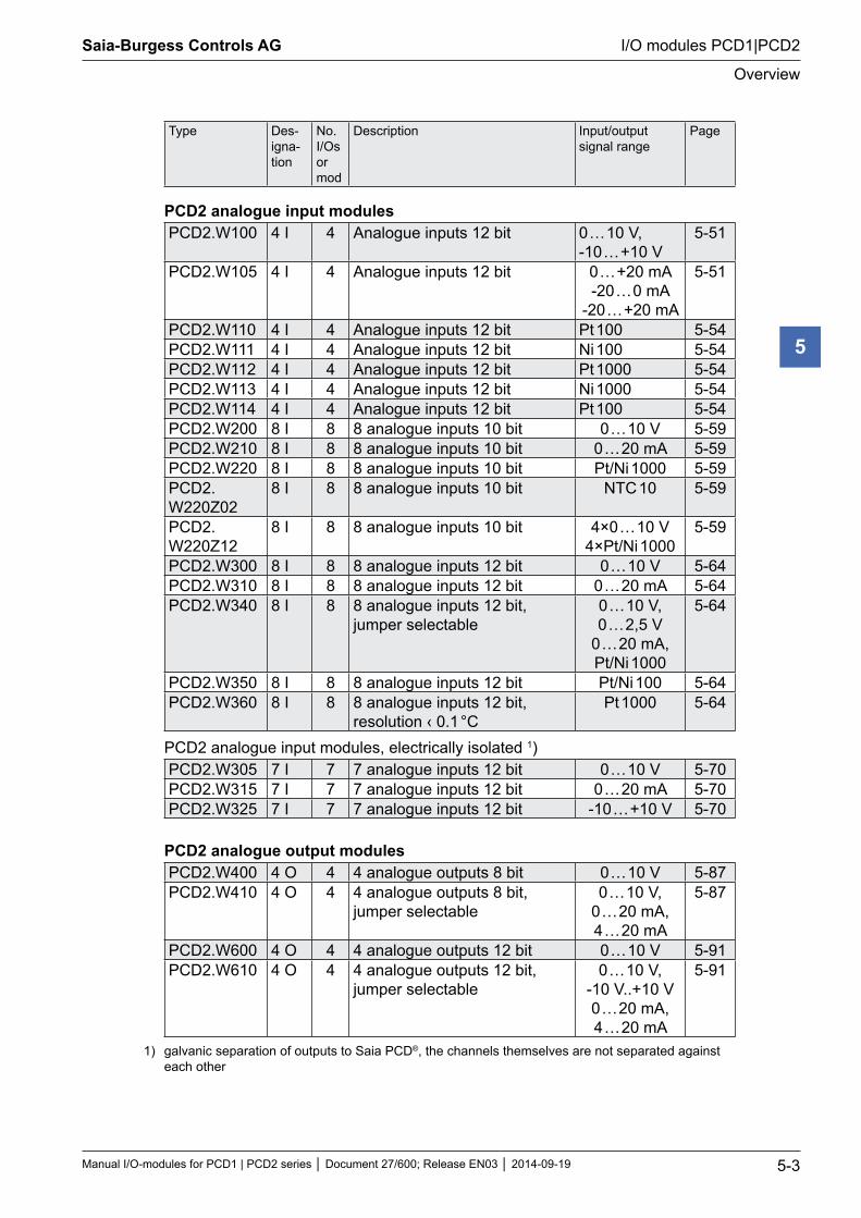
PCD2 analogue input modulesPCD2.W100 4 I 4 Analogue inputs 12 bit 0 … 10 V,
-10 … +10 V5-51
PCD2.W105 4 I 4 Analogue inputs 12 bit 0 … +20 mA -20 … 0 mA
-20 … +20 mA
5-51
PCD2.W110 4 I 4 Analogue inputs 12 bit Pt 100 5-54PCD2.W111 4 I 4 Analogue inputs 12 bit Ni 100 5-54PCD2.W112 4 I 4 Analogue inputs 12 bit Pt 1000 5-54PCD2.W113 4 I 4 Analogue inputs 12 bit Ni 1000 5-54PCD2.W114 4 I 4 Analogue inputs 12 bit Pt 100 5-54PCD2.W200 8 I 8 8 analogue inputs 10 bit 0 … 10 V 5-59PCD2.W210 8 I 8 8 analogue inputs 10 bit 0 … 20 mA 5-59PCD2.W220 8 I 8 8 analogue inputs 10 bit Pt/Ni 1000 5-59PCD2.W220Z02
8 I 8 8 analogue inputs 10 bit NTC 10 5-59
PCD2.W220Z12
8 I 8 8 analogue inputs 10 bit 4×0 … 10 V 4×Pt/Ni 1000
5-59
PCD2.W300 8 I 8 8 analogue inputs 12 bit 0 … 10 V 5-64PCD2.W310 8 I 8 8 analogue inputs 12 bit 0 … 20 mA 5-64PCD2.W340 8 I 8 8 analogue inputs 12 bit,
jumper selectable0 … 10 V, 0 … 2,5 V
0 … 20 mA, Pt/Ni 1000
5-64
PCD2.W350 8 I 8 8 analogue inputs 12 bit Pt/Ni 100 5-64PCD2.W360 8 I 8 8 analogue inputs 12 bit,
resolution ‹ 0.1 °CPt 1000 5-64
PCD2 analogue input modules, electrically isolated 1) PCD2.W305 7 I 7 7 analogue inputs 12 bit 0 … 10 V 5-70PCD2.W315 7 I 7 7 analogue inputs 12 bit 0 … 20 mA 5-70PCD2.W325 7 I 7 7 analogue inputs 12 bit -10 … +10 V 5-70
PCD2 analogue output modulesPCD2.W400 4 O 4 4 analogue outputs 8 bit 0 … 10 V 5-87PCD2.W410 4 O 4 4 analogue outputs 8 bit,
jumper selectable0 … 10 V,
0 … 20 mA, 4 … 20 mA
5-87
PCD2.W600 4 O 4 4 analogue outputs 12 bit 0 … 10 V 5-91PCD2.W610 4 O 4 4 analogue outputs 12 bit,
jumper selectable0 … 10 V,
-10 V..+10 V 0 … 20 mA, 4 … 20 mA
5-91
1) galvanic separation of outputs to Saia PCD®, the channels themselves are not separated against each other
Saia-Burgess Controls AG
Manual I/O-modules for PCD1 | PCD2 series Document 27/600; Release EN03 2014-09-19 5-4
I/O modules PCD1|PCD2
Overview
5
Type Des-igna-tion
No. I/Os or mod
Description Input/output signal range
Page
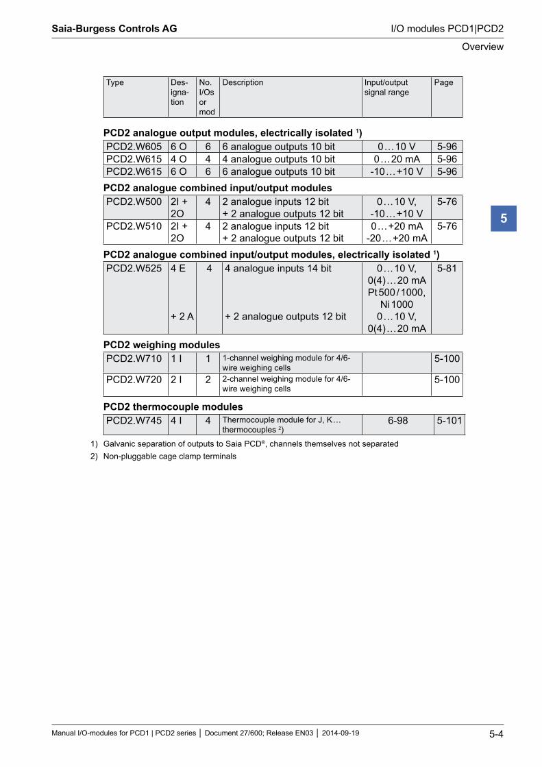
PCD2 analogue output modules, electrically isolated 1) PCD2.W605 6 O 6 6 analogue outputs 10 bit 0 … 10 V 5-96PCD2.W615 4 O 4 4 analogue outputs 10 bit 0 … 20 mA 5-96PCD2.W615 6 O 6 6 analogue outputs 10 bit -10 … +10 V 5-96
PCD2 analogue combined input/output modulesPCD2.W500 2I +
2O4 2 analogue inputs 12 bit
+ 2 analogue outputs 12 bit0 … 10 V,
-10 … +10 V5-76
PCD2.W510 2I + 2O
4 2 analogue inputs 12 bit + 2 analogue outputs 12 bit
0 … +20 mA -20 … +20 mA
5-76
PCD2 analogue combined input/output modules, electrically isolated 1) PCD2.W525 4 E
+ 2 A
4 4 analogue inputs 14 bit
+ 2 analogue outputs 12 bit
0 … 10 V, 0(4) … 20 mA Pt 500 / 1000,
Ni 10000 … 10 V,
0(4) … 20 mA
5-81
PCD2 weighing modulesPCD2.W710 1 I 1 1-channel weighing module for 4/6-
wire weighing cells5-100
PCD2.W720 2 I 2 2-channel weighing module for 4/6-wire weighing cells
5-100
PCD2 thermocouple modulesPCD2.W745 4 I 4 Thermocouple module for J, K …
thermocouples 2)6-98 5-101
1) Galvanic separation of outputs to Saia PCD®, channels themselves not separated2) Non-pluggable cage clamp terminals
Saia-Burgess Controls AG
Manual I/O-modules for PCD1 | PCD2 series Document 27/600; Release EN03 2014-09-19 5-5
I/O modules PCD1|PCD2
Overview
5
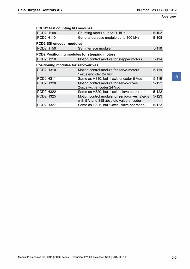
PCCD2 fast counting I/O modulesPCD2.H100 Counting module up to 20 kHz 5-103PCD2.H110 General purpose module up to 100 kHz 5-108
PCD2 SSI encoder modulesPCD2.H150 SSI interface module 5-110
PCD2 Positioning modules for stepping motorsPCD2.H210 Motion control module for stepper motors 5-114
Positioning modules for servo-drivesPCD2.H310 Motion control module for servo-motors
1-axis encoder 24 VDC5-119
PCD2.H311 Same as H310, but 1-axis encoder 5 VDC 5-119PCD2.H320 Motion control module for servo-drives
2-axis with encoder 24 VDC5-123
PCD2.H322 Same as H320, but 1-axis (slave operation) 5-123PCD2.H325 Motion control module for servo-drives, 2-axis
with 5 V and SSI absolute value encoder5-123
PCD2.H327 Same as H325, but 1-axis (slave operation) 5-123
Saia-Burgess Controls AG
Manual I/O-modules for PCD1 | PCD2 series Document 27/600; Release EN03 2014-09-19 5-6
I/O modules PCD1|PCD2
Overview
5
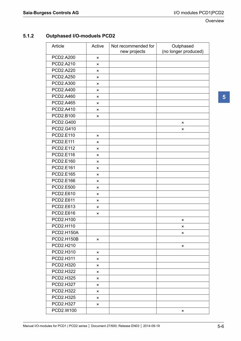
5.1.2 Outphased I/O-moduels PCD2
Article Active Not recommended for new projects
Outphased (no longer produced)
PCD2.A200 ×PCD2.A210 ×PCD2.A220 ×PCD2.A250 ×PCD2.A300 ×PCD2.A400 ×PCD2.A460 ×PCD2.A465 ×PCD2.A410 ×PCD2.B100 ×PCD2.G400 ×PCD2.G410 ×PCD2.E110 ×PCD2.E111 ×PCD2.E112 ×PCD2.E116 ×PCD2.E160 ×PCD2.E161 ×PCD2.E165 ×PCD2.E166 ×PCD2.E500 ×PCD2.E610 ×PCD2.E611 ×PCD2.E613 ×PCD2.E616 ×PCD2.H100 ×PCD2.H110 ×PCD2.H150A ×PCD2.H150B ×PCD2.H210 ×PCD2.H310 ×PCD2.H311 ×PCD2.H320 ×PCD2.H322 ×PCD2.H325 ×PCD2.H327 ×PCD2.H322 ×PCD2.H325 ×PCD2.H327 ×PCD2.W100 ×
Saia-Burgess Controls AG
Manual I/O-modules for PCD1 | PCD2 series Document 27/600; Release EN03 2014-09-19 5-7
I/O modules PCD1|PCD2
Overview
5
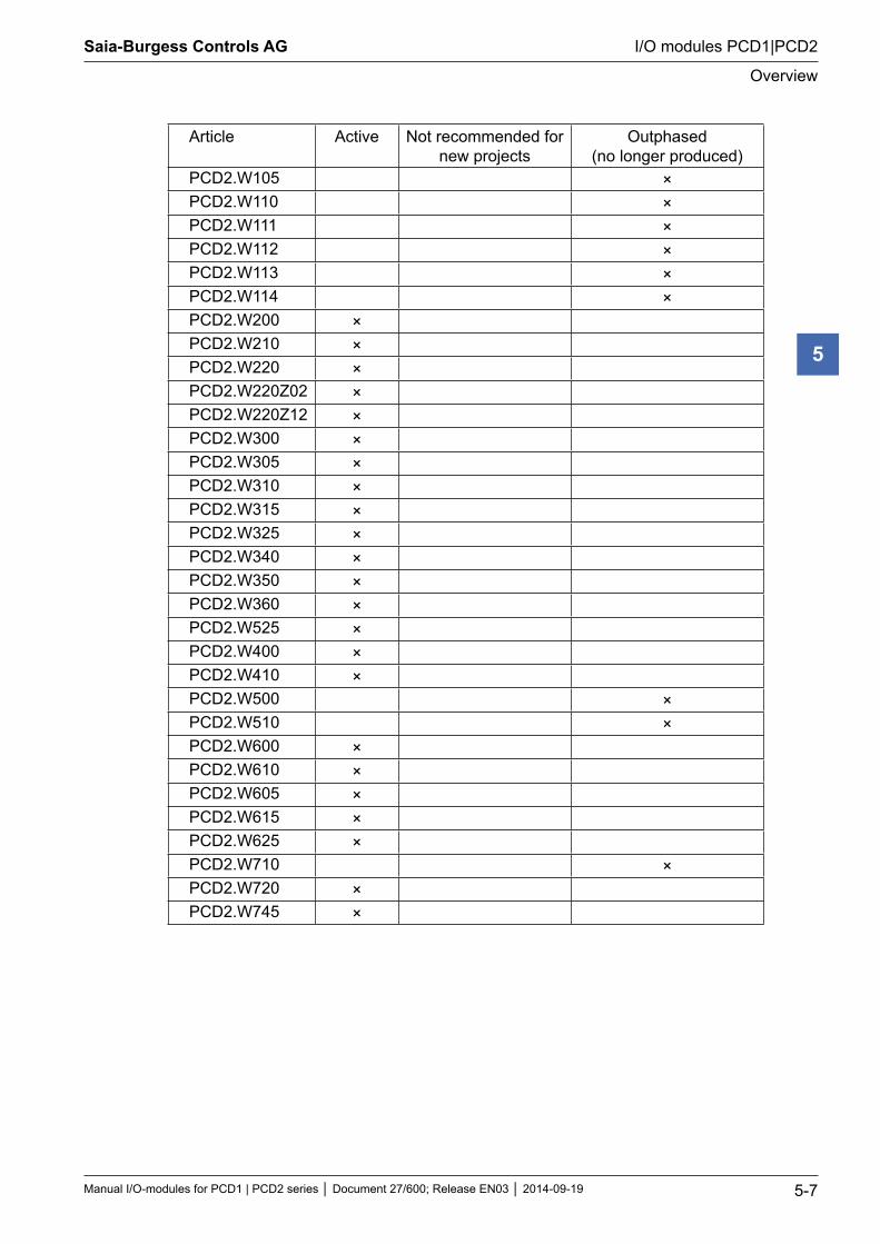
Article Active Not recommended for new projects
Outphased (no longer produced)
PCD2.W105 ×PCD2.W110 ×PCD2.W111 ×PCD2.W112 ×PCD2.W113 ×PCD2.W114 ×PCD2.W200 ×PCD2.W210 ×PCD2.W220 ×PCD2.W220Z02 ×PCD2.W220Z12 ×PCD2.W300 ×PCD2.W305 ×PCD2.W310 ×PCD2.W315 ×PCD2.W325 ×PCD2.W340 ×PCD2.W350 ×PCD2.W360 ×PCD2.W525 ×PCD2.W400 ×PCD2.W410 ×PCD2.W500 ×PCD2.W510 ×PCD2.W600 ×PCD2.W610 ×PCD2.W605 ×PCD2.W615 ×PCD2.W625 ×PCD2.W710 ×PCD2.W720 ×PCD2.W745 ×
Saia-Burgess Controls AG
Manual I/O-modules for PCD1 | PCD2 series Document 27/600; Release EN03 2014-09-19 5-8
I/O modules PCD1|PCD2
Overview
5
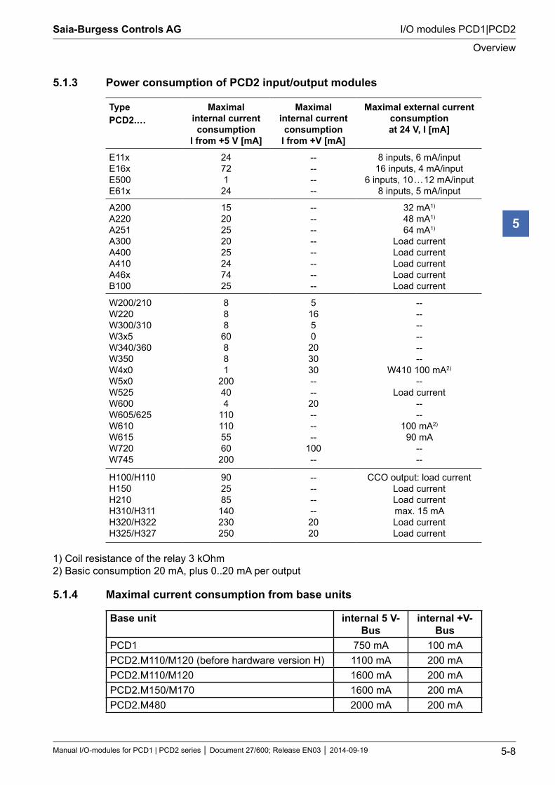
5.1.3 Power consumption of PCD2 input/output modules
TypePCD2.…
Maximal internal current consumption
I from +5 V [mA]
Maximal internal current consumption
I from +V [mA]
Maximal external current consumptionat 24 V, I [mA]
E11xE16x E500E61x
24721
24
--------
8 inputs, 6 mA/input16 inputs, 4 mA/input
6 inputs, 10 … 12 mA/input8 inputs, 5 mA/input
A200A220A251 A300A400A410A46x B100
1520252025247425
----------------
32 mA1)
48 mA1)
64 mA1)
Load currentLoad currentLoad currentLoad currentLoad current
W200/210W220W300/310W3x5W340/360W350W4x0W5x0W525W600W605/625W610W615W720W745
888
60881
200404
1101105560
200
51650
203030----20------
100--
------------
W410 100 mA2)
--Load current
----
100 mA2)
90 mA----
H100/H110H150H210H310/H311H320/H322H325/H327
902585
140230250
--------2020
CCO output: load current Load current Load current max. 15 mA Load current Load current
1) Coil resistance of the relay 3 kOhm 2) Basic consumption 20 mA, plus 0..20 mA per output
5.1.4 Maximal current consumption from base units
Base unit internal 5 V-Bus
internal +V-Bus
PCD1 750 mA 100 mAPCD2.M110/M120 (before hardware version H) 1100 mA 200 mAPCD2.M110/M120 1600 mA 200 mAPCD2.M150/M170 1600 mA 200 mAPCD2.M480 2000 mA 200 mA
Saia-Burgess Controls AG
Manual I/O-modules for PCD1 | PCD2 series Document 27/600; Release EN03 2014-09-19 5-9
I/O modules PCD1|PCD2
Digital I/O modules
5
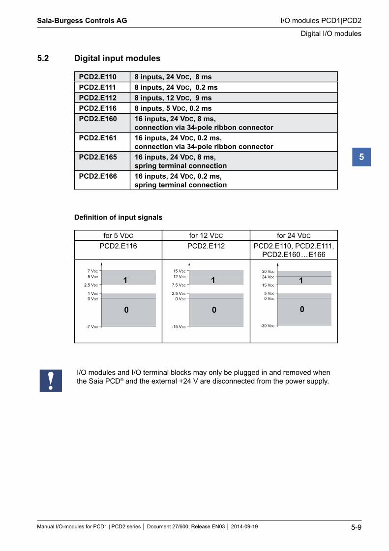
5.2 Digital input modules
PCD2.E110 8 inputs, 24 VDC, 8 msPCD2.E111 8 inputs, 24 VDC, 0.2 msPCD2.E112 8 inputs, 12 VDC, 9 msPCD2.E116 8 inputs, 5 VDC, 0.2 msPCD2.E160 16 inputs, 24 VDC, 8 ms,
connection via 34-pole ribbon connectorPCD2.E161 16 inputs, 24 VDC, 0.2 ms,
connection via 34-pole ribbon connectorPCD2.E165 16 inputs, 24 VDC, 8 ms,
spring terminal connection PCD2.E166 16 inputs, 24 VDC, 0.2 ms,
spring terminal connection
Definition of input signals
for 5 VDC for 12 VDC for 24 VDC
PCD2.E116 PCD2.E112 PCD2.E110, PCD2.E111, PCD2.E160 … E166
7 VDC
5 VDC
2.5 VDC
0 VDC
1 VDC
-7 VDC
1
0
15 VDC
12 VDC
7.5 VDC
0 VDC
2.5 VDC
-15 VDC
1
0
30 VDC
24 VDC
15 VDC
0 VDC
5 VDC
-30 VDC
1
0
I/O modules and I/O terminal blocks may only be plugged in and removed when the Saia PCD® and the external +24 V are disconnected from the power supply.
Saia-Burgess Controls AG
Manual I/O-modules for PCD1 | PCD2 series Document 27/600; Release EN03 2014-09-19 5-10
I/O modules PCD1|PCD2
PCD2.E110, PCD2.E111, PCD2.E112 and PCD2.E116
5
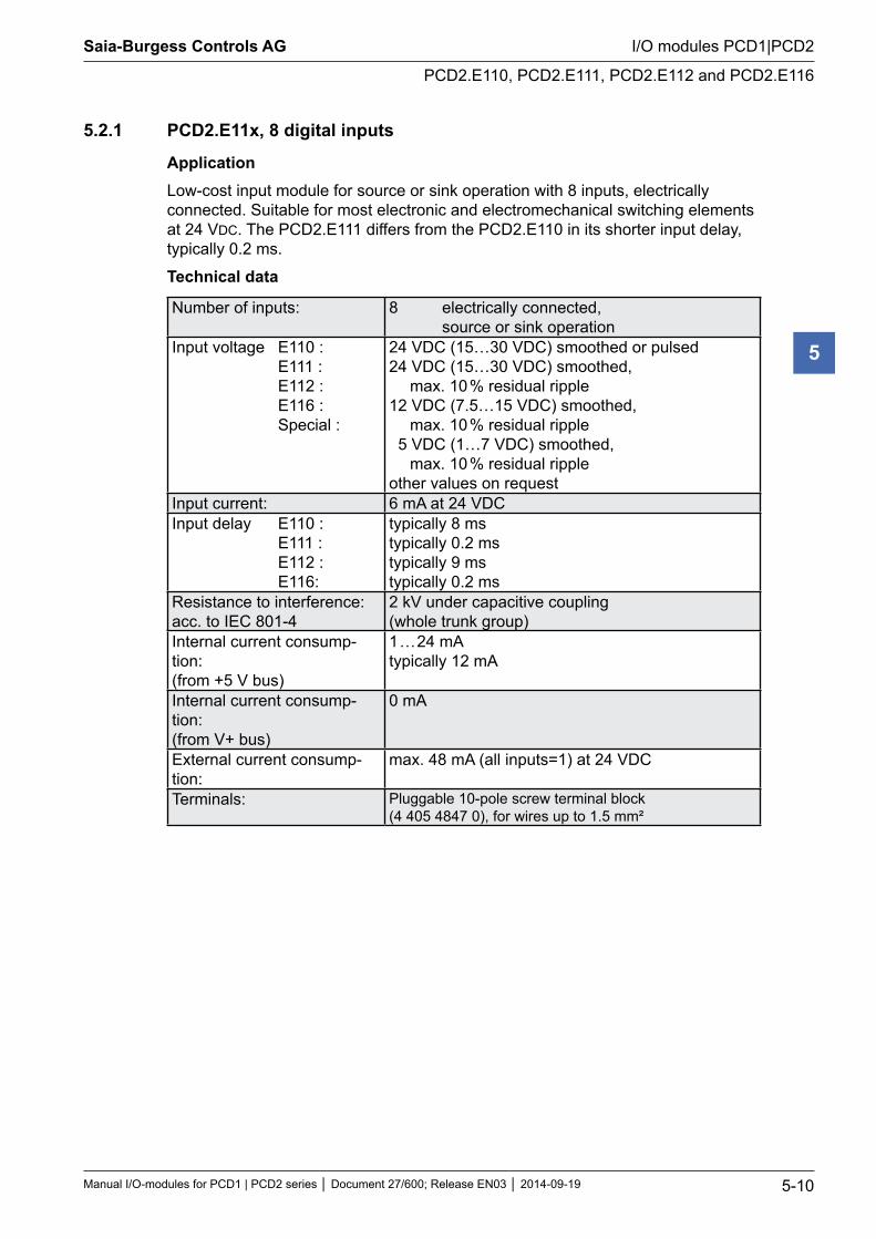
5.2.1 PCD2.E11x, 8 digital inputs
ApplicationLow-cost input module for source or sink operation with 8 inputs, electrically connected. Suitable for most electronic and electromechanical switching elements at 24 VDC. The PCD2.E111 differs from the PCD2.E110 in its shorter input delay, typically 0.2 ms.
Technical data
Number of inputs: 8 electrically connected, source or sink operation
Input voltage E110 : E111 : E112 : E116 : Special :
24 VDC (15…30 VDC) smoothed or pulsed24 VDC (15…30 VDC) smoothed,
max. 10 % residual ripple12 VDC (7.5…15 VDC) smoothed,
max. 10 % residual ripple 5 VDC (1…7 VDC) smoothed,
max. 10 % residual ripple other values on request
Input current: 6 mA at 24 VDC Input delay E110 : E111 : E112 : E116:
typically 8 ms typically 0.2 ms typically 9 ms typically 0.2 ms
Resistance to interference: acc. to IEC 801-4
2 kV under capacitive coupling (whole trunk group)
Internal current consump-tion: (from +5 V bus)
1 … 24 mA typically 12 mA
Internal current consump-tion: (from V+ bus)
0 mA
External current consump-tion:
max. 48 mA (all inputs=1) at 24 VDC
Terminals: Pluggable 10-pole screw terminal block (4 405 4847 0), for wires up to 1.5 mm²
Saia-Burgess Controls AG
Manual I/O-modules for PCD1 | PCD2 series Document 27/600; Release EN03 2014-09-19 5-11
I/O modules PCD1|PCD2
PCD2.E110, PCD2.E111, PCD2.E112 and PCD2.E116
5
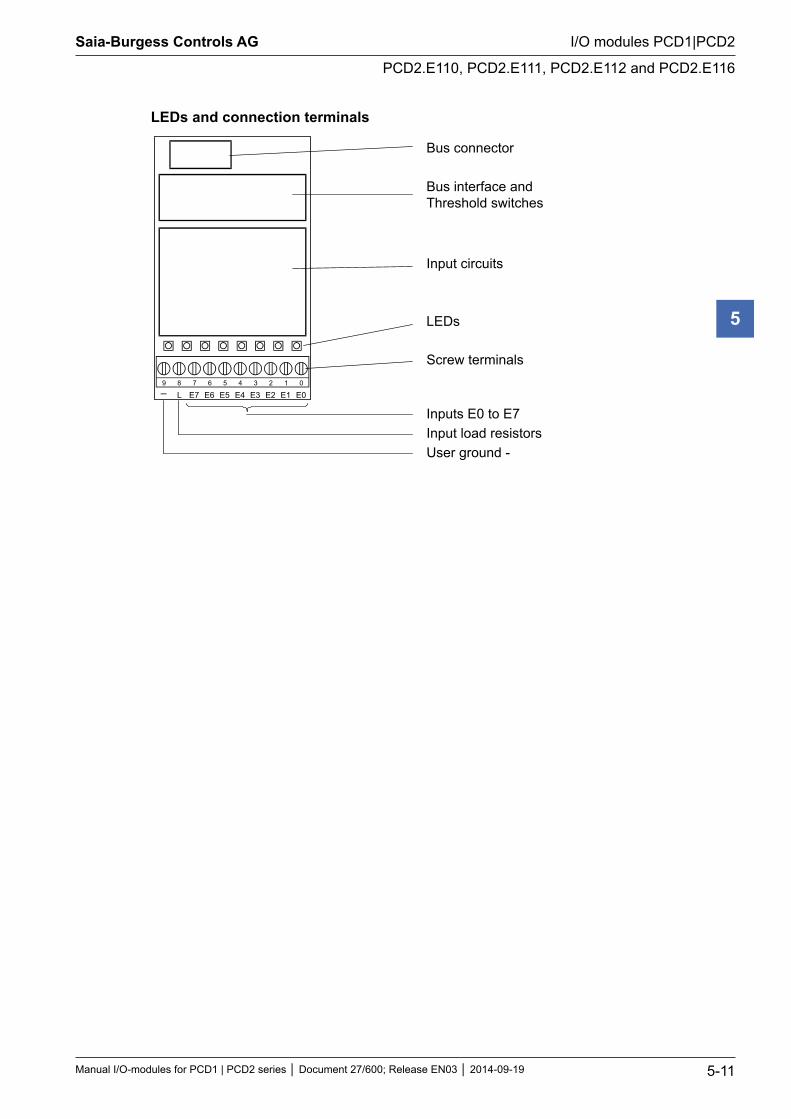
LEDs and connection terminals
9 8 7 6 5 4 3 2 1 0
E0E1E2E3E4E5E6E7L
Bus connector
Bus interface andThreshold switches
Input circuits
LEDs
Screw terminals
Inputs E0 to E7Input load resistorsUser ground -
Saia-Burgess Controls AG
Manual I/O-modules for PCD1 | PCD2 series Document 27/600; Release EN03 2014-09-19 5-12
I/O modules PCD1|PCD2
PCD2.E110, PCD2.E111, PCD2.E112 and PCD2.E116
5
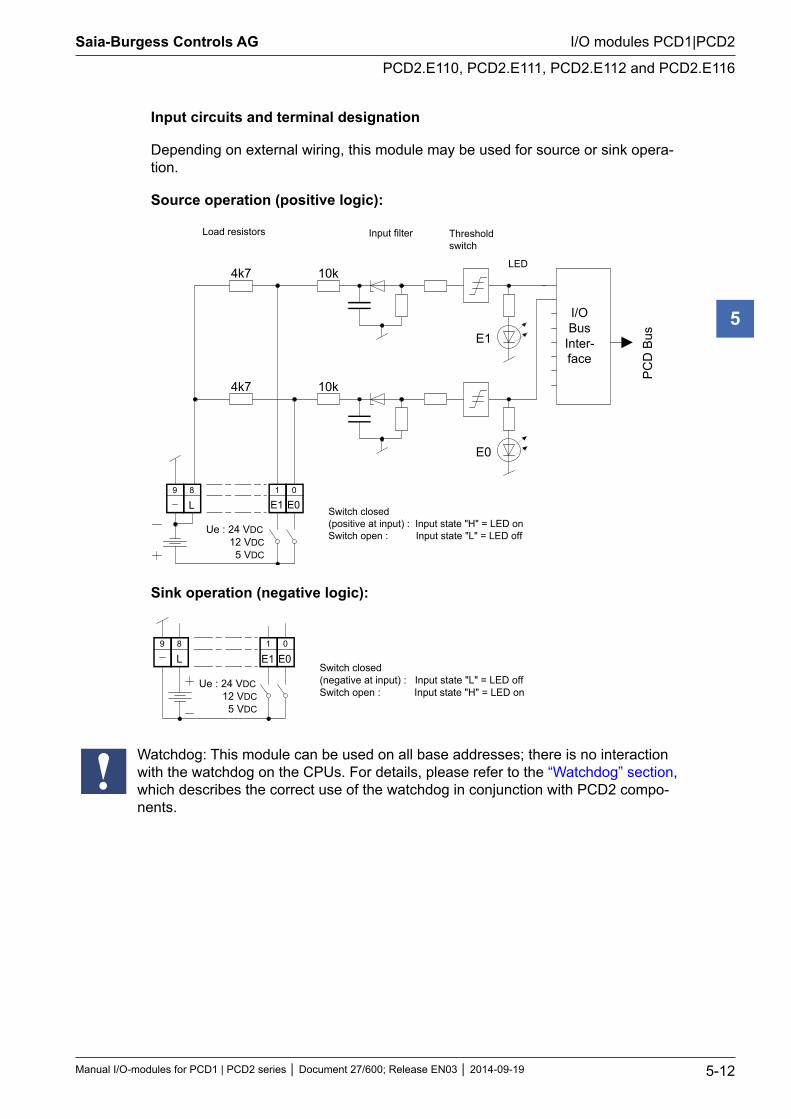
Input circuits and terminal designation
Depending on external wiring, this module may be used for source or sink opera-tion.
Source operation (positive logic):
E1
4k7
4k7
10k
10k
E0
01
L89
E0E1
I/OBus
Inter-face
PC
D B
us
Ue : 24 VDC 12 VDC 5 VDC
Load resistors Input filter Thresholdswitch
LED
Switch closed(positive at input) : Input state "H" = LED onSwitch open : Input state "L" = LED off
Sink operation (negative logic):
E00
E11
L89
Switch closed(negative at input) : Input state "L" = LED offSwitch open : Input state "H" = LED on
Ue : 24 VDC 12 VDC 5 VDC
Watchdog: This module can be used on all base addresses; there is no interaction with the watchdog on the CPUs. For details, please refer to the “Watchdog” section, which describes the correct use of the watchdog in conjunction with PCD2 compo-nents.
Saia-Burgess Controls AG
Manual I/O-modules for PCD1 | PCD2 series Document 27/600; Release EN03 2014-09-19 5-13
I/O modules PCD1|PCD2
PCD2.E160/161
5
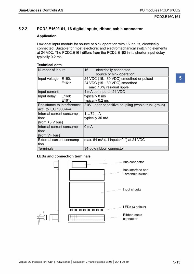
5.2.2 PCD2.E160/161, 16 digital inputs, ribbon cable connector
Application
Low-cost input module for source or sink operation with 16 inputs, electrically connected. Suitable for most electronic and electromechanical switching elements at 24 VDC. The PCD2.E161 differs from the PCD2.E160 in its shorter input delay, typically 0.2 ms.
Technical data Number of inputs: 16 electrically connected,
source or sink operationInput voltage E160: E161:
24 VDC (15…30 VDC) smoothed or pulsed24 VDC (15…30 VDC) smoothed
max. 10 % residual rippleInput current: 4 mA per input at 24 VDCInput delay E160: E161:
typically 8 ms typically 0.2 ms
Resistance to interference: acc. to IEC 1000-4-4
2 kV under capacitive coupling (whole trunk group)
Internal current consump-tion: (from +5 V bus)
1 … 72 mA typically 36 mA
Internal current consump-tion: (from V+ bus)
0 mA
External current consump-tion
max. 64 mA (all inputs=”1”) at 24 VDC
Terminals: 34-pole ribbon connector
LEDs and connection terminals
Bus connector
Bus interface andThreshold switch
Input circuits
LEDs (3 colour)
Ribbon cableconnector
Saia-Burgess Controls AG
Manual I/O-modules for PCD1 | PCD2 series Document 27/600; Release EN03 2014-09-19 5-14
I/O modules PCD1|PCD2
PCD2.E160/161
5
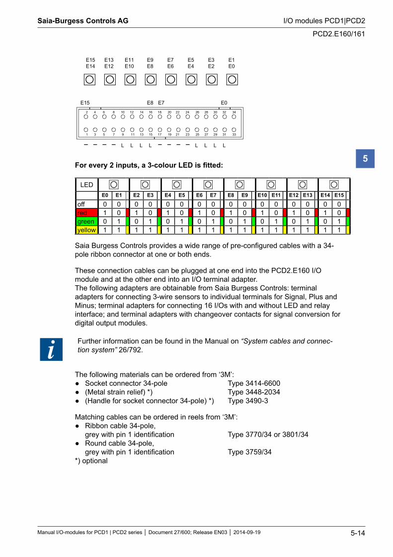
2 4 6 8 10 12 14 16 18 20 22 24 26 28 30 32 34
1 3 5 7 9 11 13 15 17 19 21 23 25 27 29 31 33
E15 E0E8 E7
L L L L L L L L
E15E14
E13E12
E11E10
E9E8
E7E6
E5E4
E3E2
E1E0
For every 2 inputs, a 3-colour LED is fitted:
LEDE0 E1 E2 E3 E4 E5 E6 E7 E8 E9 E10 E11 E12 E13 E14 E15
off 0 0 0 0 0 0 0 0 0 0 0 0 0 0 0 0red 1 0 1 0 1 0 1 0 1 0 1 0 1 0 1 0green 0 1 0 1 0 1 0 1 0 1 0 1 0 1 0 1yellow 1 1 1 1 1 1 1 1 1 1 1 1 1 1 1 1
Saia Burgess Controls provides a wide range of pre-configured cables with a 34-pole ribbon connector at one or both ends.
These connection cables can be plugged at one end into the PCD2.E160 I/O module and at the other end into an I/O terminal adapter. The following adapters are obtainable from Saia Burgess Controls: terminal adapters for connecting 3-wire sensors to individual terminals for Signal, Plus and Minus; terminal adapters for connecting 16 I/Os with and without LED and relay interface; and terminal adapters with changeover contacts for signal conversion for digital output modules.
Further information can be found in the Manual on “System cables and connec-tion system” 26/792.
The following materials can be ordered from ‘3M’: Socket connector 34-pole Type 3414-6600 (Metal strain relief) *) Type 3448-2034 (Handle for socket connector 34-pole) *) Type 3490-3
Matching cables can be ordered in reels from ‘3M’: Ribbon cable 34-pole, grey with pin 1 identification Type 3770/34 or 3801/34 Round cable 34-pole, grey with pin 1 identification Type 3759/34 *) optional
Saia-Burgess Controls AG
Manual I/O-modules for PCD1 | PCD2 series Document 27/600; Release EN03 2014-09-19 5-15
I/O modules PCD1|PCD2
PCD2.E160/161
5
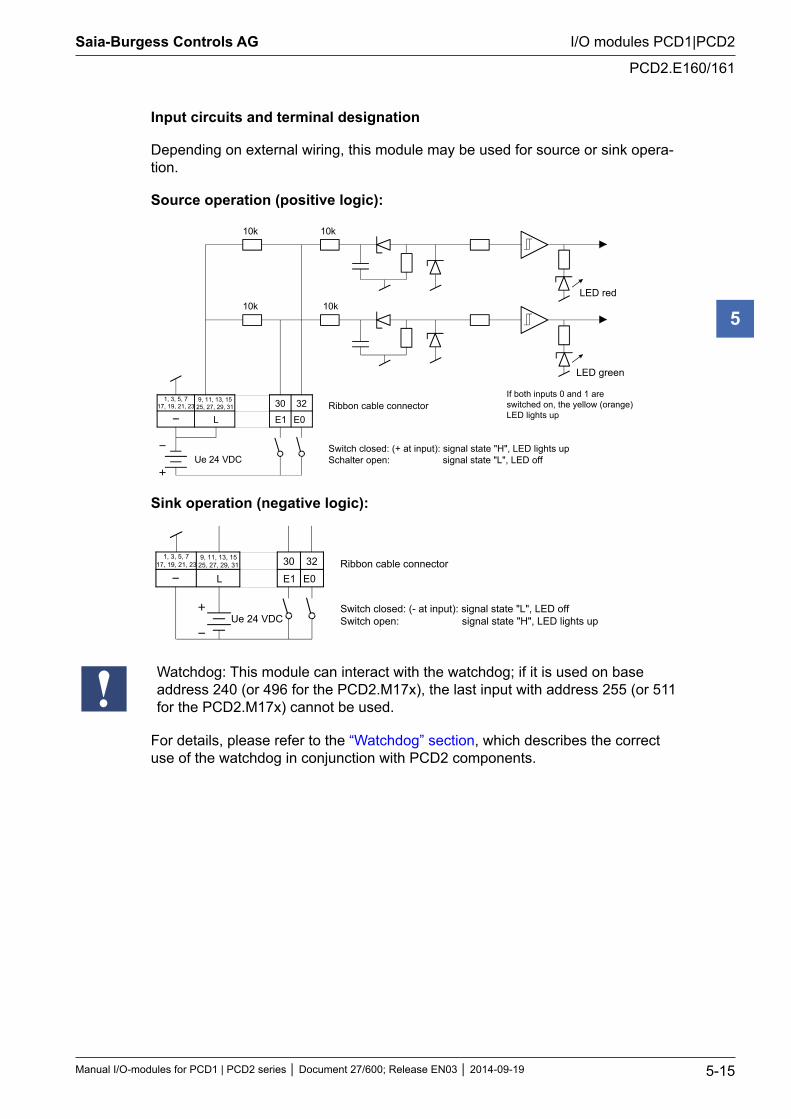
Input circuits and terminal designation
Depending on external wiring, this module may be used for source or sink opera-tion.
Source operation (positive logic):
1, 3, 5, 717, 19, 21, 23
9, 11, 13, 1525, 27, 29, 31
L E1 E0
30 32
10k 10k
10k 10k
Ue 24 VDC
Ribbon cable connector
Switch closed: (+ at input): signal state "H", LED lights upSchalter open: signal state "L", LED off
LED red
LED green
If both inputs 0 and 1 areswitched on, the yellow (orange)LED lights up
Sink operation (negative logic):
1, 3, 5, 717, 19, 21, 23
9, 11, 13, 1525, 27, 29, 31
L E1 E0
30 32
Ue 24 VDC
Ribbon cable connector
Switch closed: (- at input): signal state "L", LED offSwitch open: signal state "H", LED lights up
Watchdog: This module can interact with the watchdog; if it is used on base address 240 (or 496 for the PCD2.M17x), the last input with address 255 (or 511 for the PCD2.M17x) cannot be used.
For details, please refer to the “Watchdog” section, which describes the correct use of the watchdog in conjunction with PCD2 components.
Saia-Burgess Controls AG
Manual I/O-modules for PCD1 | PCD2 series Document 27/600; Release EN03 2014-09-19 5-16
I/O modules PCD1|PCD2
PCD2.E165/166
5
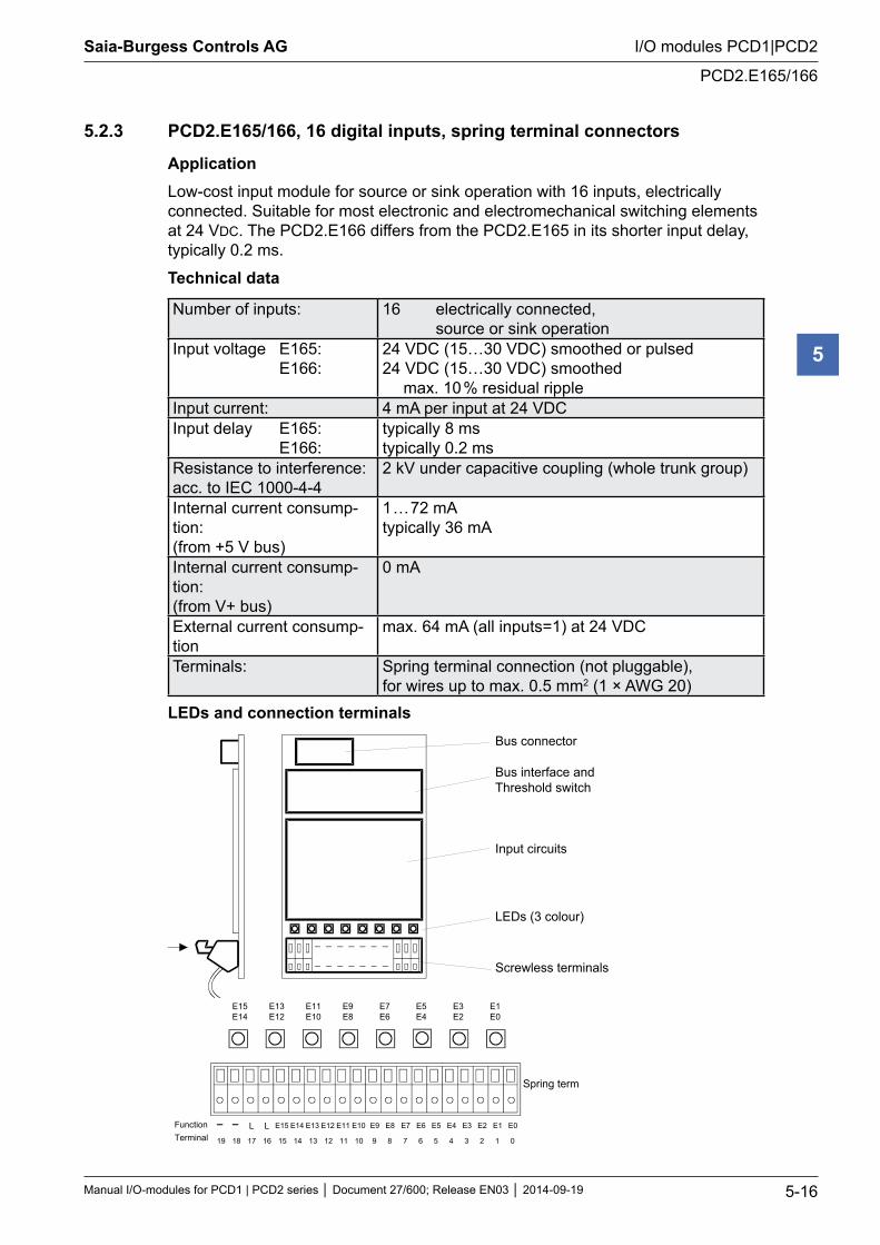
5.2.3 PCD2.E165/166, 16 digital inputs, spring terminal connectors
ApplicationLow-cost input module for source or sink operation with 16 inputs, electrically connected. Suitable for most electronic and electromechanical switching elements at 24 VDC. The PCD2.E166 differs from the PCD2.E165 in its shorter input delay, typically 0.2 ms.
Technical data
Number of inputs: 16 electrically connected, source or sink operation
Input voltage E165: E166:
24 VDC (15…30 VDC) smoothed or pulsed24 VDC (15…30 VDC) smoothed
max. 10 % residual rippleInput current: 4 mA per input at 24 VDC Input delay E165: E166:
typically 8 ms typically 0.2 ms
Resistance to interference: acc. to IEC 1000-4-4
2 kV under capacitive coupling (whole trunk group)
Internal current consump-tion: (from +5 V bus)
1 … 72 mA typically 36 mA
Internal current consump-tion: (from V+ bus)
0 mA
External current consump-tion
max. 64 mA (all inputs=1) at 24 VDC
Terminals: Spring terminal connection (not pluggable), for wires up to max. 0.5 mm2 (1 × AWG 20)
LEDs and connection terminalsBus connector
Bus interface andThreshold switch
Input circuits
LEDs (3 colour)
Screwless terminals
E15E14
E13E12
E11E10
E9E8
E7E6
E5E4
E3E2
E1E0
E15 E14 E13 E12 E11 E10 E9 E8 E7 E6 E5 E4 E3 E2 E1 E0
Spring terminal
FunctionTerminal 15 14 13 12 11 1019 18 17 16 9 8 7 6 5 4 3 2 1 0
L L
Saia-Burgess Controls AG
Manual I/O-modules for PCD1 | PCD2 series Document 27/600; Release EN03 2014-09-19 5-17
I/O modules PCD1|PCD2
PCD2.E165/166
5
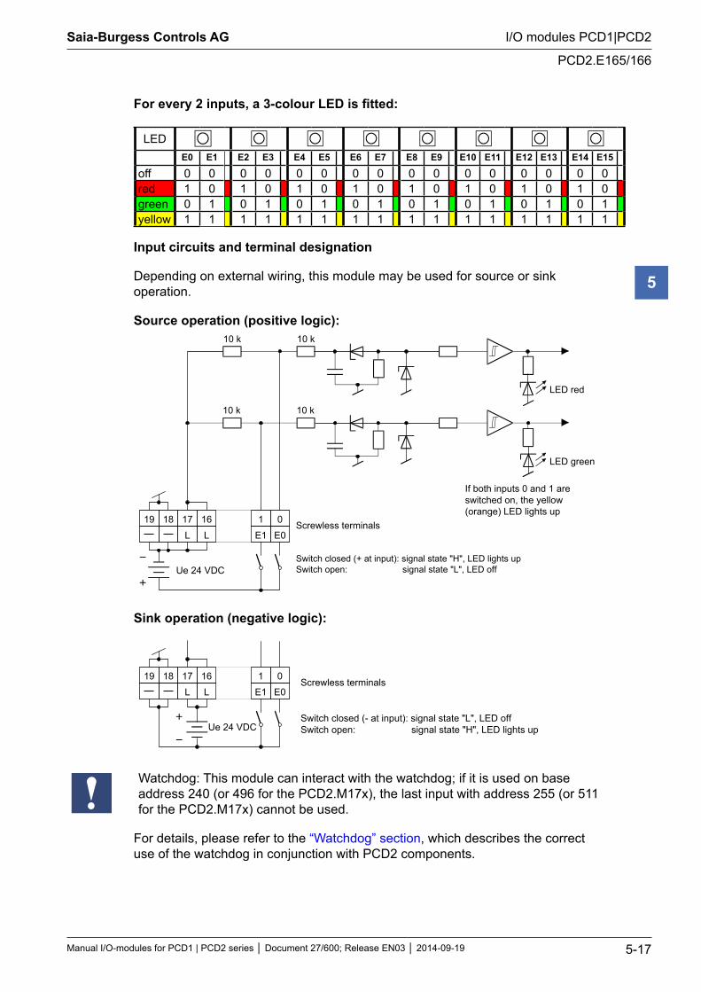
For every 2 inputs, a 3-colour LED is fitted:
LEDE0 E1 E2 E3 E4 E5 E6 E7 E8 E9 E10 E11 E12 E13 E14 E15
off 0 0 0 0 0 0 0 0 0 0 0 0 0 0 0 0red 1 0 1 0 1 0 1 0 1 0 1 0 1 0 1 0green 0 1 0 1 0 1 0 1 0 1 0 1 0 1 0 1yellow 1 1 1 1 1 1 1 1 1 1 1 1 1 1 1 1
Input circuits and terminal designation
Depending on external wiring, this module may be used for source or sink operation.
Source operation (positive logic):10 k 10 k
10 k 10 k
E1 E0L L19 18 17 16 1 0
Ue 24 VDC
LED red
LED green
Screwless terminals
If both inputs 0 and 1 areswitched on, the yellow (orange) LED lights up
Switch closed (+ at input): signal state "H", LED lights upSwitch open: signal state "L", LED off
Sink operation (negative logic):
E1 E0L L19 18 17 16 1 0
Switch closed (- at input): signal state "L", LED offSwitch open: signal state "H", LED lights up
Screwless terminals
Ue 24 VDC
Watchdog: This module can interact with the watchdog; if it is used on base address 240 (or 496 for the PCD2.M17x), the last input with address 255 (or 511 for the PCD2.M17x) cannot be used.
For details, please refer to the “Watchdog” section, which describes the correct use of the watchdog in conjunction with PCD2 components.
Saia-Burgess Controls AG
Manual I/O-modules for PCD1 | PCD2 series Document 27/600; Release EN03 2014-09-19 5-18
I/O modules PCD1|PCD2
Digital input modules, electrically isolated
5
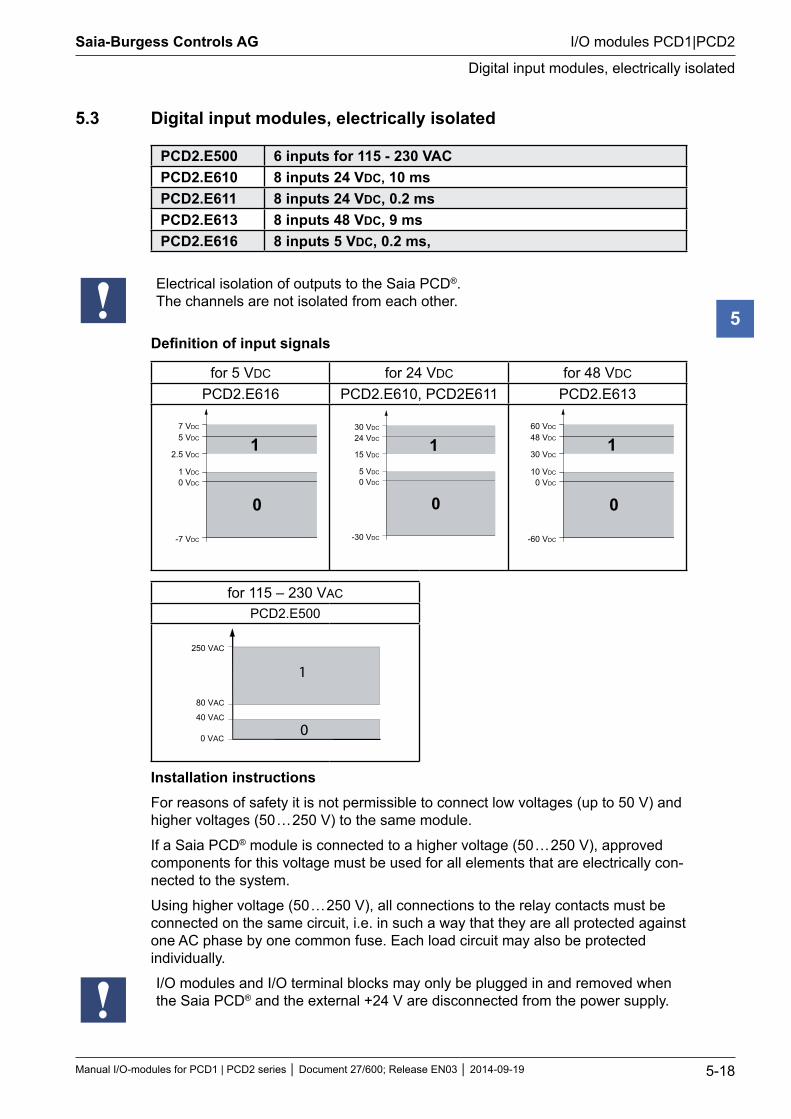
5.3 Digital input modules, electrically isolated
PCD2.E500 6 inputs for 115 - 230 VACPCD2.E610 8 inputs 24 VDC, 10 ms PCD2.E611 8 inputs 24 VDC, 0.2 ms PCD2.E613 8 inputs 48 VDC, 9 ms PCD2.E616 8 inputs 5 VDC, 0.2 ms,
Electrical isolation of outputs to the Saia PCD®. The channels are not isolated from each other.
Definition of input signals
for 5 VDC for 24 VDC for 48 VDC
PCD2.E616 PCD2.E610, PCD2E611 PCD2.E613
7 VDC
5 VDC
2.5 VDC
0 VDC
1 VDC
-7 VDC
1
0
30 VDC
24 VDC
15 VDC
0 VDC
5 VDC
-30 VDC
1
0
60 VDC
48 VDC
30 VDC
0 VDC
10 VDC
-60 VDC
1
0
for 115 – 230 VAC
PCD2.E500
1
0
250 VAC
80 VAC
40 VAC
0 VAC
Installation instructionsFor reasons of safety it is not permissible to connect low voltages (up to 50 V) and higher voltages (50 … 250 V) to the same module.
If a Saia PCD® module is connected to a higher voltage (50 … 250 V), approved components for this voltage must be used for all elements that are electrically con-nected to the system.
Using higher voltage (50 … 250 V), all connections to the relay contacts must be connected on the same circuit, i.e. in such a way that they are all protected against one AC phase by one common fuse. Each load circuit may also be protected individually.
I/O modules and I/O terminal blocks may only be plugged in and removed when the Saia PCD® and the external +24 V are disconnected from the power supply.
Saia-Burgess Controls AG
Manual I/O-modules for PCD1 | PCD2 series Document 27/600; Release EN03 2014-09-19 5-19
I/O modules PCD1|PCD2
PCD2.E500
5
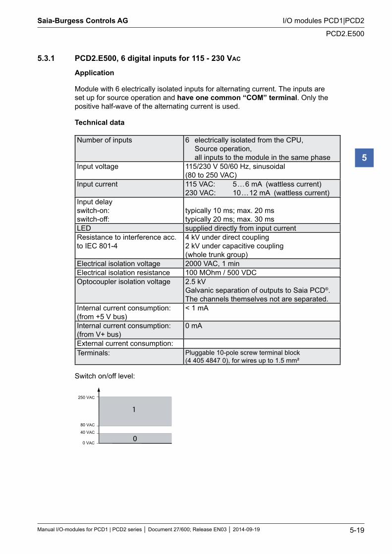
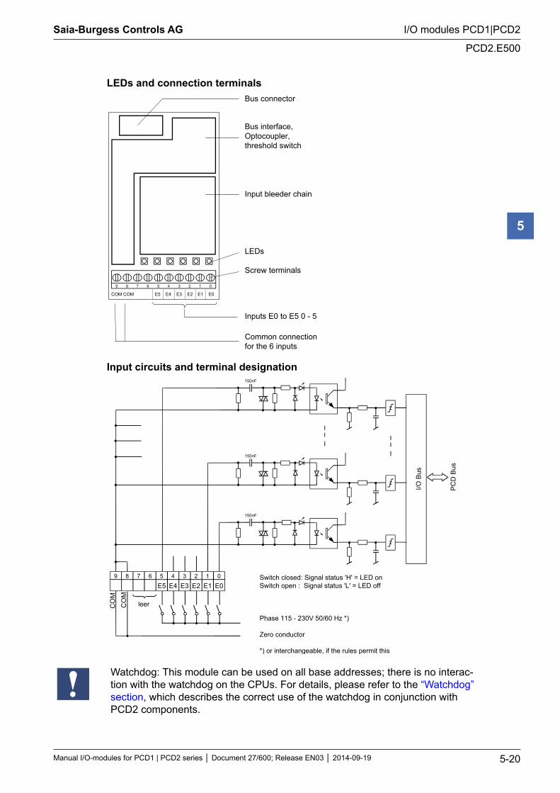
5.3.1 PCD2.E500, 6 digital inputs for 115 - 230 VAC
Application
Module with 6 electrically isolated inputs for alternating current. The inputs are set up for source operation and have one common “COM” terminal. Only the positive half-wave of the alternating current is used.
Technical data
Number of inputs 6 electrically isolated from the CPU, Source operation, all inputs to the module in the same phase
Input voltage 115/230 V 50/60 Hz, sinusoidal (80 to 250 VAC)
Input current 115 VAC: 5 … 6 mA (wattless current) 230 VAC: 10 … 12 mA (wattless current)
Input delay switch-on: switch-off:
typically 10 ms; max. 20 ms typically 20 ms; max. 30 ms
LED supplied directly from input currentResistance to interference acc. to IEC 801-4
4 kV under direct coupling 2 kV under capacitive coupling (whole trunk group)
Electrical isolation voltage 2000 VAC, 1 minElectrical isolation resistance 100 MOhm / 500 VDCOptocoupler isolation voltage 2.5 kV
Galvanic separation of outputs to Saia PCD®. The channels themselves not are separated.
Internal current consumption: (from +5 V bus)
< 1 mA
Internal current consumption: (from V+ bus)
0 mA
External current consumption:Terminals: Pluggable 10-pole screw terminal block
(4 405 4847 0), for wires up to 1.5 mm²
Switch on/off level:
1
0
250 VAC
80 VAC
40 VAC
0 VAC
Saia-Burgess Controls AG
Manual I/O-modules for PCD1 | PCD2 series Document 27/600; Release EN03 2014-09-19 5-20
I/O modules PCD1|PCD2
PCD2.E500
5
LEDs and connection terminals
9 8 7 6 5 4 3 2 1 0
E0E1E2E3E4E5COM COM
Bus connector Bus interface,Optocoupler,threshold switch
Input bleeder chain LEDs Screw terminals Inputs E0 to E5 0 - 5
Common connectionfor the 6 inputs
Input circuits and terminal designation
89 7 6 5
E54
E43
E32
E21
E10
E0
150nF
150nF
150nF
I/O B
us
PC
D B
us
leer
Switch closed: Signal status 'H' = LED onSwitch open : Signal status 'L' = LED off
Phase 115 - 230V 50/60 Hz *)
Zero conductor *)
*) or interchangeable, if the rules permit this
CO
MC
OM
Watchdog: This module can be used on all base addresses; there is no interac-tion with the watchdog on the CPUs. For details, please refer to the “Watchdog” section, which describes the correct use of the watchdog in conjunction with PCD2 components.
Saia-Burgess Controls AG
Manual I/O-modules for PCD1 | PCD2 series Document 27/600; Release EN03 2014-09-19 5-21
I/O modules PCD1|PCD2
PCD2.E61x
5
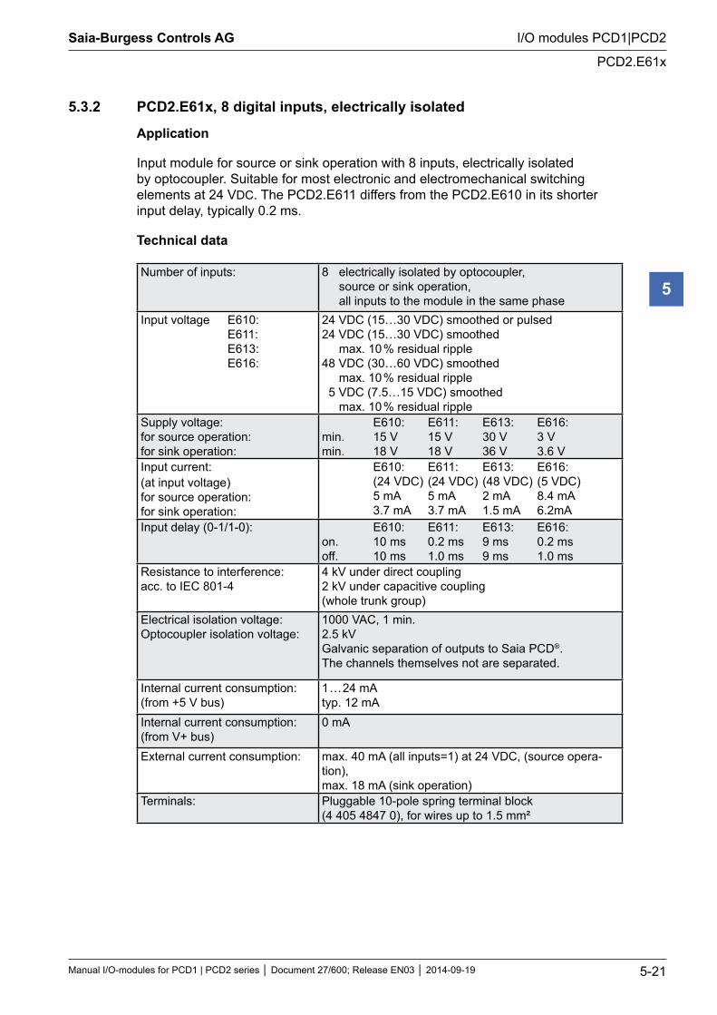
5.3.2 PCD2.E61x, 8 digital inputs, electrically isolated
Application
Input module for source or sink operation with 8 inputs, electrically isolated by optocoupler. Suitable for most electronic and electromechanical switching elements at 24 VDC. The PCD2.E611 differs from the PCD2.E610 in its shorter input delay, typically 0.2 ms.
Technical data
Number of inputs: 8 electrically isolated by optocoupler, source or sink operation, all inputs to the module in the same phase
Input voltage E610: E611: E613: E616:
24 VDC (15…30 VDC) smoothed or pulsed24 VDC (15…30 VDC) smoothed
max. 10 % residual ripple48 VDC (30…60 VDC) smoothed
max. 10 % residual ripple 5 VDC (7.5…15 VDC) smoothed
max. 10 % residual rippleSupply voltage: for source operation: for sink operation:
E610: E611: E613: E616: min. 15 V 15 V 30 V 3 V min. 18 V 18 V 36 V 3.6 V
Input current: (at input voltage) for source operation: for sink operation:
E610: E611: E613: E616: (24 VDC) (24 VDC) (48 VDC) (5 VDC) 5 mA 5 mA 2 mA 8.4 mA 3.7 mA 3.7 mA 1.5 mA 6.2mA
Input delay (0-1/1-0): E610: E611: E613: E616: on. 10 ms 0.2 ms 9 ms 0.2 ms off. 10 ms 1.0 ms 9 ms 1.0 ms
Resistance to interference: acc. to IEC 801-4
4 kV under direct coupling 2 kV under capacitive coupling (whole trunk group)
Electrical isolation voltage: Optocoupler isolation voltage:
1000 VAC, 1 min. 2.5 kV Galvanic separation of outputs to Saia PCD®. The channels themselves not are separated.
Internal current consumption: (from +5 V bus)
1 … 24 mA typ. 12 mA
Internal current consumption: (from V+ bus)
0 mA
External current consumption: max. 40 mA (all inputs=1) at 24 VDC, (source opera-tion), max. 18 mA (sink operation)
Terminals: Pluggable 10-pole spring terminal block (4 405 4847 0), for wires up to 1.5 mm²
Saia-Burgess Controls AG
Manual I/O-modules for PCD1 | PCD2 series Document 27/600; Release EN03 2014-09-19 5-22
I/O modules PCD1|PCD2
PCD2.E61x
5
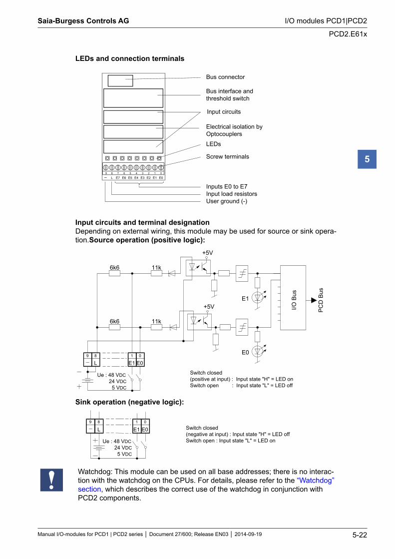
LEDs and connection terminals
9 8 7 6 5 4 3 2 1 0
E0E1E2E3E4E5E6E7L
Bus connector Bus interface andthreshold switch
Input circuits Electrical isolation byOptocouplers
LEDs Screw terminals
Inputs E0 to E7Input load resistorsUser ground (-)
Input circuits and terminal designation Depending on external wiring, this module may be used for source or sink opera-tion.Source operation (positive logic):
+5V
E0
E1
6k6
6k6
11k
11k
+5V
E0 E1 L 8 9 0 1
I/O B
us
Ue : 48 VDC 24 VDC 5 VDC
Switch closed (positive at input) : Input state "H" = LED on Switch open : Input state "L" = LED off
PC
D B
us
Sink operation (negative logic):
E0 E1 1
L 8 9 0
Switch closed (negative at input) : Input state "H" = LED off Switch open : Input state "L" = LED on Ue : 48 VDC
24 VDC 5 VDC
Watchdog: This module can be used on all base addresses; there is no interac-tion with the watchdog on the CPUs. For details, please refer to the “Watchdog” section, which describes the correct use of the watchdog in conjunction with PCD2 components.
Saia-Burgess Controls AG
Manual I/O-modules for PCD1 | PCD2 series Document 27/600; Release EN03 2014-09-19 5-23
I/O modules PCD1|PCD2
Digital output modules
5
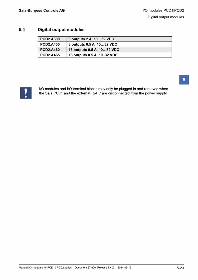
5.4 Digital output modules
PCD2.A300 6 outputs 2 A, 10…32 VDCPCD2.A400 8 outputs 0.5 A, 10…32 VDCPCD2.A460 16 outputs 0.5 A, 10…32 VDCPCD2.A465 16 outputs 0.5 A, 10..32 VDC
I/O modules and I/O terminal blocks may only be plugged in and removed when the Saia PCD® and the external +24 V are disconnected from the power supply.
Saia-Burgess Controls AG
Manual I/O-modules for PCD1 | PCD2 series Document 27/600; Release EN03 2014-09-19 5-24
I/O modules PCD1|PCD2
PCD2.A300
5
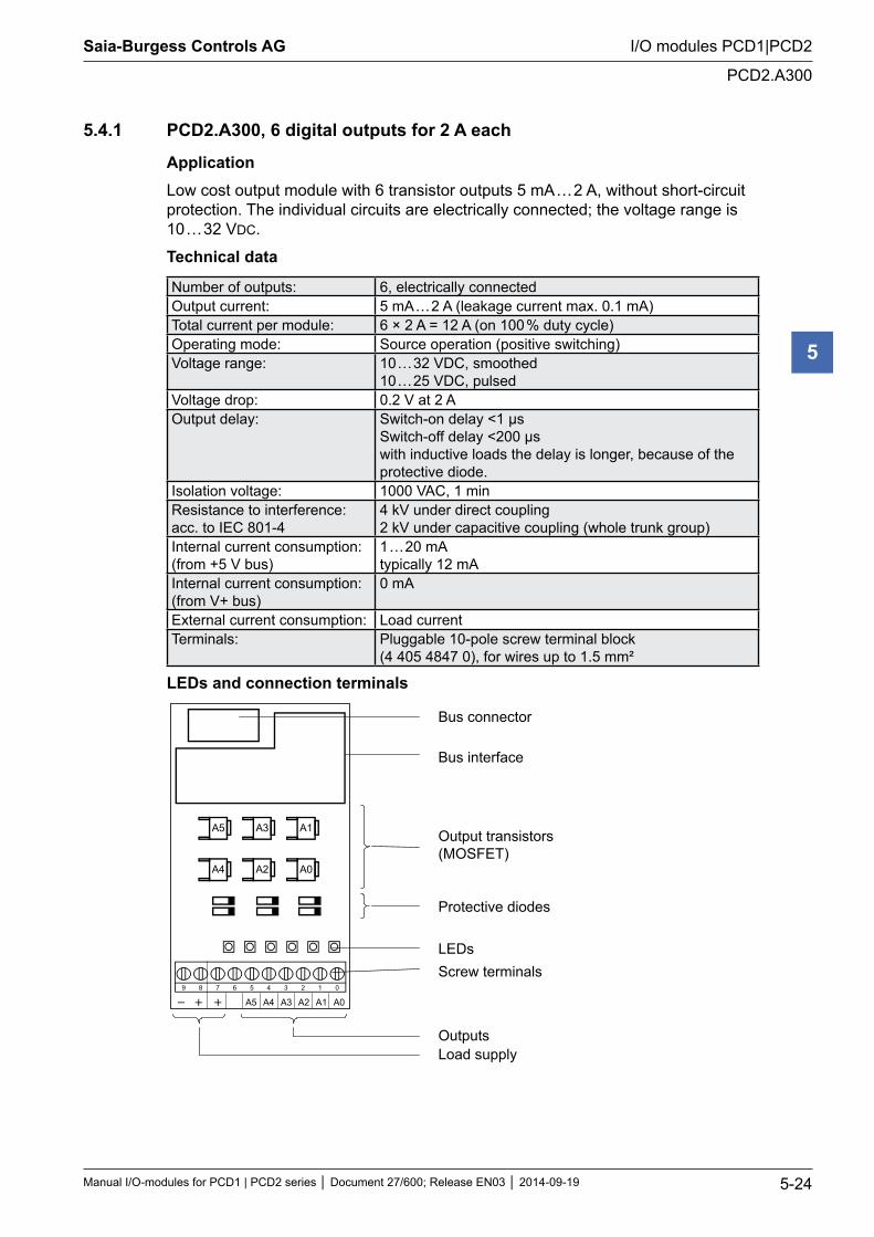
5.4.1 PCD2.A300, 6 digital outputs for 2 A each
ApplicationLow cost output module with 6 transistor outputs 5 mA … 2 A, without short-circuit protection. The individual circuits are electrically connected; the voltage range is 10 … 32 VDC.
Technical data
Number of outputs: 6, electrically connectedOutput current: 5 mA … 2 A (leakage current max. 0.1 mA)Total current per module: 6 × 2 A = 12 A (on 100 % duty cycle)Operating mode: Source operation (positive switching)Voltage range: 10 … 32 VDC, smoothed
10 … 25 VDC, pulsedVoltage drop: 0.2 V at 2 AOutput delay: Switch-on delay <1 µs
Switch-off delay <200 µs with inductive loads the delay is longer, because of the protective diode.
Isolation voltage: 1000 VAC, 1 minResistance to interference: acc. to IEC 801-4
4 kV under direct coupling 2 kV under capacitive coupling (whole trunk group)
Internal current consumption: (from +5 V bus)
1 … 20 mA typically 12 mA
Internal current consumption: (from V+ bus)
0 mA
External current consumption: Load currentTerminals: Pluggable 10-pole screw terminal block
(4 405 4847 0), for wires up to 1.5 mm²
LEDs and connection terminals
Bus connector
Bus interface
Output transistors(MOSFET)
Protective diodes
LEDs Screw terminals
OutputsLoad supply
9 8 7 6 5 4 3 2 1 0
A0A1A2A3A4A5
A5 A3 A1
A4 A2 A0
Saia-Burgess Controls AG
Manual I/O-modules for PCD1 | PCD2 series Document 27/600; Release EN03 2014-09-19 5-25
I/O modules PCD1|PCD2
PCD2.A300
5
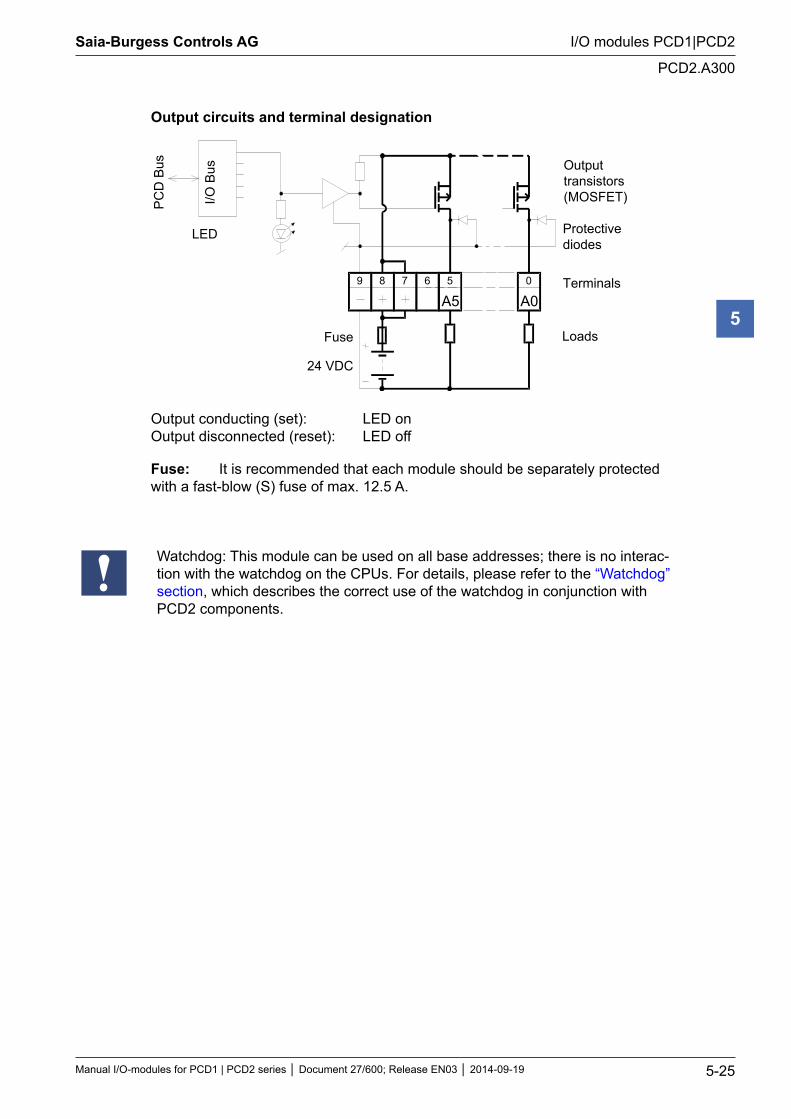
Output circuits and terminal designation
A0089 7
I/O B
us
PC
D B
us
24 VDC
Fuse
6 5
A5
Outputtransistors(MOSFET)
Protectivediodes
Terminals
Loads
LEDaddress A5
Output conducting (set): LED on Output disconnected (reset): LED off
Fuse: It is recommended that each module should be separately protected with a fast-blow (S) fuse of max. 12.5 A.
Watchdog: This module can be used on all base addresses; there is no interac-tion with the watchdog on the CPUs. For details, please refer to the “Watchdog” section, which describes the correct use of the watchdog in conjunction with PCD2 components.
Saia-Burgess Controls AG
Manual I/O-modules for PCD1 | PCD2 series Document 27/600; Release EN03 2014-09-19 5-26
I/O modules PCD1|PCD2
PCD2.A400
5
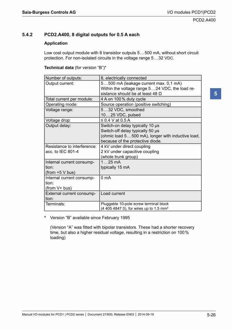
5.4.2 PCD2.A400, 8 digital outputs for 0.5 A each
Application
Low cost output module with 8 transistor outputs 5 … 500 mA, without short circuit protection. For non-isolated circuits in the voltage range 5 … 32 VDC.
Technical data (for version “B”)*
Number of outputs: 8, electrically connectedOutput current: 5 … 500 mA (leakage current max. 0,1 mA)
Within the voltage range 5 … 24 VDC, the load re-sistance should be at least 48 Ω
Total current per module: 4 A on 100 % duty cycleOperating mode: Source operation (positive switching)Voltage range: 5 … 32 VDC, smoothed
10 … 25 VDC, pulsedVoltage drop: ≤ 0.4 V at 0.5 AOutput delay: Switch-on delay typically 10 µs
Switch-off delay typically 50 µs (ohmic load 5 … 500 mA), longer with inductive load, because of the protective diode.
Resistance to interference: acc. to IEC 801-4
4 kV under direct coupling 2 kV under capacitive coupling (whole trunk group)
Internal current consump-tion: (from +5 V bus)
1 … 25 mA typically 15 mA
Internal current consump-tion: (from V+ bus)
0 mA
External current consump-tion:
Load current
Terminals: Pluggable 10-pole screw terminal block (4 405 4847 0), for wires up to 1.5 mm²
* Version “B” available since February 1995
(Version “A” was fitted with bipolar transistors. These had a shorter recovery time, but also a higher residual voltage, resulting in a restriction on 100 % loading)
Saia-Burgess Controls AG
Manual I/O-modules for PCD1 | PCD2 series Document 27/600; Release EN03 2014-09-19 5-27
I/O modules PCD1|PCD2
PCD2.A400
5
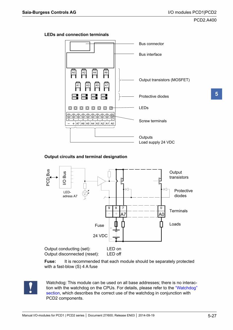
LEDs and connection terminals Bus connector
Bus interface Output transistors (MOSFET) Protective diodes LEDs
Screw terminals Outputs Load supply 24 VDC
9 8 7 6 5 4 3 2 1 0
A0A1A2A3A4A5A6A7
A0 A2 A4 A6
A7A5A3A1
Output circuits and terminal designation
A0089 7
I/O B
us
PC
D B
us
24 VDC
Fuse
A7
Outputtransistors
Protectivediodes
Terminals
Loads
LED-adress A7
Output conducting (set): LED on Output disconnected (reset): LED off
Fuse: It is recommended that each module should be separately protected with a fast-blow (S) 4 A fuse
Watchdog: This module can be used on all base addresses; there is no interac-tion with the watchdog on the CPUs. For details, please refer to the “Watchdog” section, which describes the correct use of the watchdog in conjunction with PCD2 components.
Saia-Burgess Controls AG
Manual I/O-modules for PCD1 | PCD2 series Document 27/600; Release EN03 2014-09-19 5-28
I/O modules PCD1|PCD2
PCD2.A460
5
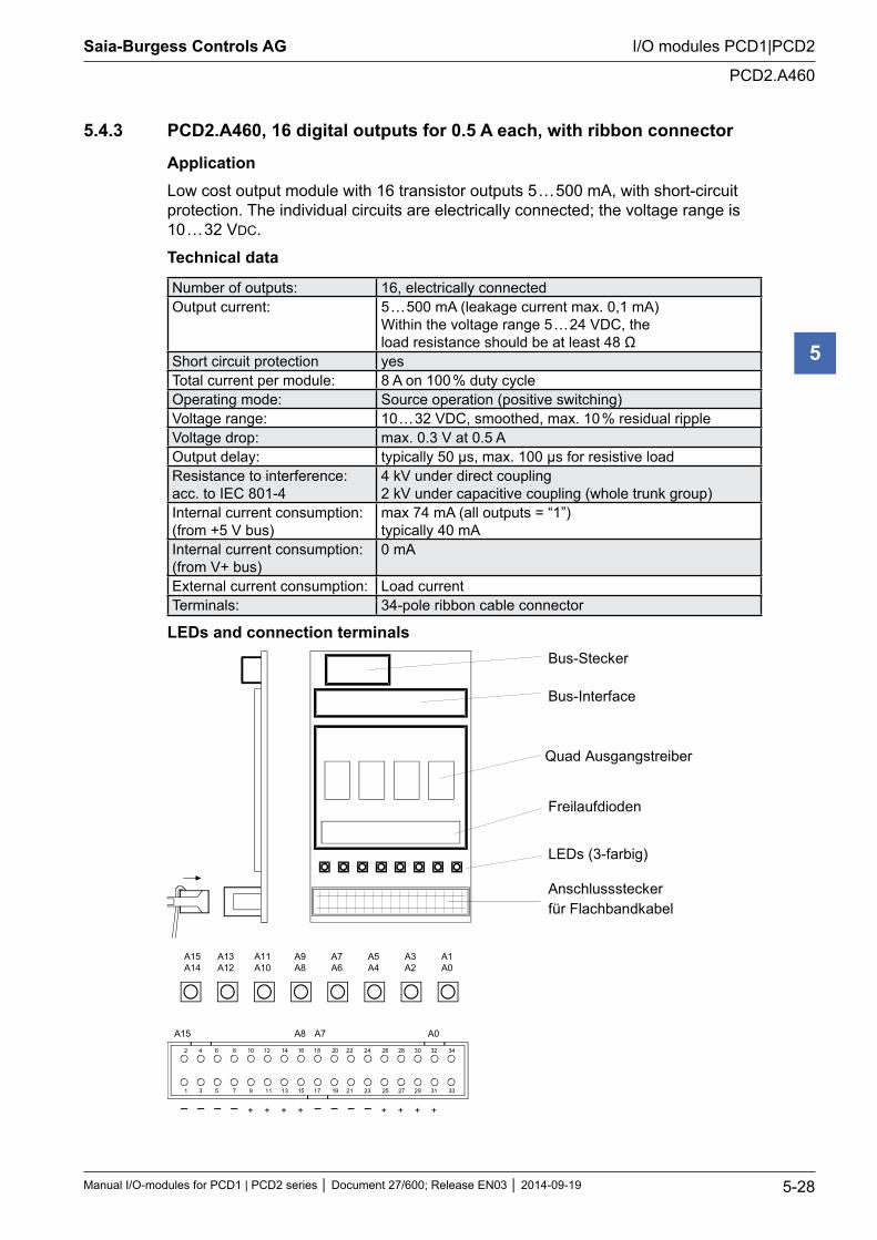
5.4.3 PCD2.A460, 16 digital outputs for 0.5 A each, with ribbon connector
ApplicationLow cost output module with 16 transistor outputs 5 … 500 mA, with short-circuit protection. The individual circuits are electrically connected; the voltage range is 10 … 32 VDC.
Technical data
Number of outputs: 16, electrically connectedOutput current: 5 … 500 mA (leakage current max. 0,1 mA)
Within the voltage range 5 … 24 VDC, the load resistance should be at least 48 Ω
Short circuit protection yesTotal current per module: 8 A on 100 % duty cycleOperating mode: Source operation (positive switching)Voltage range: 10 … 32 VDC, smoothed, max. 10 % residual rippleVoltage drop: max. 0.3 V at 0.5 AOutput delay: typically 50 µs, max. 100 µs for resistive loadResistance to interference: acc. to IEC 801-4
4 kV under direct coupling 2 kV under capacitive coupling (whole trunk group)
Internal current consumption: (from +5 V bus)
max 74 mA (all outputs = “1”) typically 40 mA
Internal current consumption: (from V+ bus)
0 mA
External current consumption: Load currentTerminals: 34-pole ribbon cable connector
LEDs and connection terminals Bus-Stecker
Bus-Interface
Freilaufdioden
LEDs (3-farbig)
Anschlusssteckerfür Flachbandkabel
Quad Ausgangstreiber
2 4 6 8 10 12 14 16 18 20 22 24 26 28 30 32 34
1 3 5 7 9 11 13 15 17 19 21 23 25 27 29 31 33
A15 A0A8 A7
+ + + + + + + +
A15A14
A13A12
A11A10
A9A8
A7A6
A5A4
A3A2
A1A0
Saia-Burgess Controls AG
Manual I/O-modules for PCD1 | PCD2 series Document 27/600; Release EN03 2014-09-19 5-29
I/O modules PCD1|PCD2
PCD2.A460
5
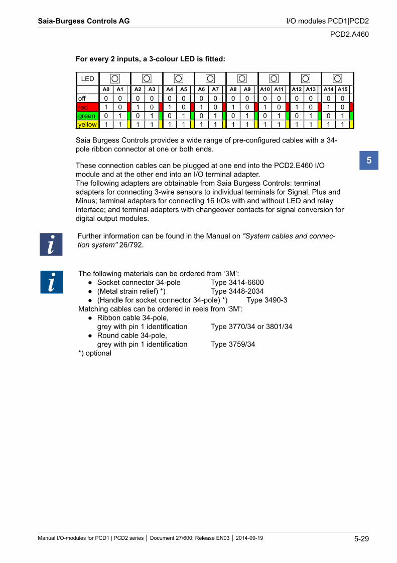
For every 2 inputs, a 3-colour LED is fitted:
LEDA0 A1 A2 A3 A4 A5 A6 A7 A8 A9 A10 A11 A12 A13 A14 A15
off 0 0 0 0 0 0 0 0 0 0 0 0 0 0 0 0red 1 0 1 0 1 0 1 0 1 0 1 0 1 0 1 0green 0 1 0 1 0 1 0 1 0 1 0 1 0 1 0 1yellow 1 1 1 1 1 1 1 1 1 1 1 1 1 1 1 1
Saia Burgess Controls provides a wide range of pre-configured cables with a 34-pole ribbon connector at one or both ends.
These connection cables can be plugged at one end into the PCD2.E460 I/O module and at the other end into an I/O terminal adapter. The following adapters are obtainable from Saia Burgess Controls: terminal adapters for connecting 3-wire sensors to individual terminals for Signal, Plus and Minus; terminal adapters for connecting 16 I/Os with and without LED and relay interface; and terminal adapters with changeover contacts for signal conversion for digital output modules.
Further information can be found in the Manual on "System cables and connec-tion system" 26/792.
The following materials can be ordered from ‘3M’: Socket connector 34-pole Type 3414-6600 (Metal strain relief) *) Type 3448-2034 (Handle for socket connector 34-pole) *) Type 3490-3
Matching cables can be ordered in reels from ‘3M’: Ribbon cable 34-pole, grey with pin 1 identification Type 3770/34 or 3801/34 Round cable 34-pole, grey with pin 1 identification Type 3759/34
*) optional
Saia-Burgess Controls AG
Manual I/O-modules for PCD1 | PCD2 series Document 27/600; Release EN03 2014-09-19 5-30
I/O modules PCD1|PCD2
PCD2.A460
5
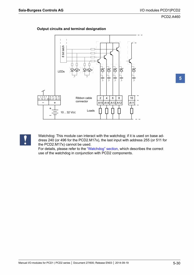
Output circuits and terminal designation
1, 3, 5, 717, 19, 21, 23
9, 11, 13, 1525, 27, 29, 31
A15 A14
2 4
10 .. 32 VDC
Ribbon cableconnector
6 8
A13 A12
10
A11
8 bi
t lat
ch
LEDs
Loads
Watchdog: This module can interact with the watchdog; if it is used on base ad-dress 240 (or 496 for the PCD2.M17x), the last input with address 255 (or 511 for the PCD2.M17x) cannot be used.For details, please refer to the “Watchdog” section, which describes the correct use of the watchdog in conjunction with PCD2 components.
Saia-Burgess Controls AG
Manual I/O-modules for PCD1 | PCD2 series Document 27/600; Release EN03 2014-09-19 5-31
I/O modules PCD1|PCD2
PCD2.A465
5
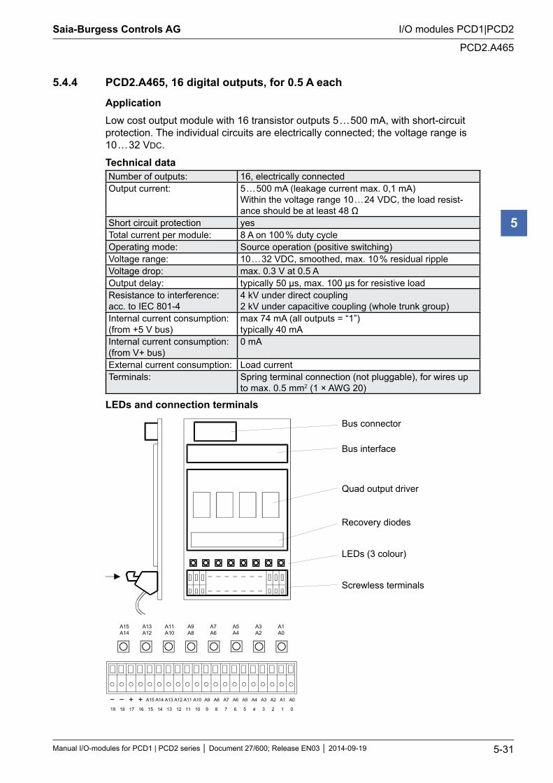
5.4.4 PCD2.A465, 16 digital outputs, for 0.5 A each
ApplicationLow cost output module with 16 transistor outputs 5 … 500 mA, with short-circuit protection. The individual circuits are electrically connected; the voltage range is 10 … 32 VDC.
Technical data Number of outputs: 16, electrically connectedOutput current: 5 … 500 mA (leakage current max. 0,1 mA)
Within the voltage range 10 … 24 VDC, the load resist-ance should be at least 48 Ω
Short circuit protection yesTotal current per module: 8 A on 100 % duty cycleOperating mode: Source operation (positive switching)Voltage range: 10 … 32 VDC, smoothed, max. 10 % residual rippleVoltage drop: max. 0.3 V at 0.5 AOutput delay: typically 50 µs, max. 100 µs for resistive loadResistance to interference: acc. to IEC 801-4
4 kV under direct coupling 2 kV under capacitive coupling (whole trunk group)
Internal current consumption: (from +5 V bus)
max 74 mA (all outputs = “1”) typically 40 mA
Internal current consumption: (from V+ bus)
0 mA
External current consumption: Load currentTerminals: Spring terminal connection (not pluggable), for wires up
to max. 0.5 mm2 (1 × AWG 20)
LEDs and connection terminals
Bus connector
Bus interface
Recovery diodes
LEDs (3 colour)
Screwless terminals
Quad output driver
A15 A14
A13 A12
A11 A10
A9 A8
A7 A6
A5 A4
A3 A2
A1 A0
A15 A14 A13 A12 A11 A10 A9 A8 A7 A6 A5 A4 A3 A2 A1 A0
15 14 13 12 11 10 19 18 17 16 9 8 7 6 5 4 3 2 1 0
Saia-Burgess Controls AG
Manual I/O-modules for PCD1 | PCD2 series Document 27/600; Release EN03 2014-09-19 5-32
I/O modules PCD1|PCD2
PCD2.A465
5
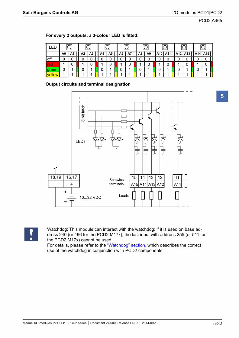
For every 2 outputs, a 3-colour LED is fitted:
LEDA0 A1 A2 A3 A4 A5 A6 A7 A8 A9 A10 A11 A12 A13 A14 A15
off 0 0 0 0 0 0 0 0 0 0 0 0 0 0 0 0red 1 0 1 0 1 0 1 0 1 0 1 0 1 0 1 0green 0 1 0 1 0 1 0 1 0 1 0 1 0 1 0 1yellow 1 1 1 1 1 1 1 1 1 1 1 1 1 1 1 1
Output circuits and terminal designation
Screwlessterminals
Loads
A15 A14
10...32 VDC
A13 A12 A11
8 bi
t lat
ch
LEDs
18,19 16,17 15 14 13 12 11
Watchdog: This module can interact with the watchdog; if it is used on base ad-dress 240 (or 496 for the PCD2.M17x), the last input with address 255 (or 511 for the PCD2.M17x) cannot be used.For details, please refer to the “Watchdog” section, which describes the correct use of the watchdog in conjunction with PCD2 components.
Saia-Burgess Controls AG
Manual I/O-modules for PCD1 | PCD2 series Document 27/600; Release EN03 2014-09-19 5-33
I/O modules PCD1|PCD2
Digital output modules, electrically isolated
5
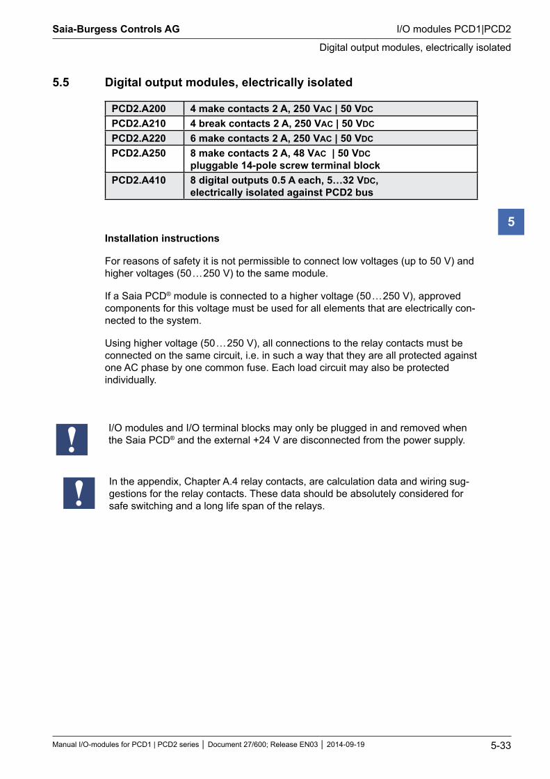
5.5 Digital output modules, electrically isolated
PCD2.A200 4 make contacts 2 A, 250 VAC | 50 VDC PCD2.A210 4 break contacts 2 A, 250 VAC | 50 VDC PCD2.A220 6 make contacts 2 A, 250 VAC | 50 VDC PCD2.A250 8 make contacts 2 A, 48 VAC | 50 VDC
pluggable 14-pole screw terminal blockPCD2.A410 8 digital outputs 0.5 A each, 5…32 VDC,
electrically isolated against PCD2 bus
Installation instructions
For reasons of safety it is not permissible to connect low voltages (up to 50 V) and higher voltages (50 … 250 V) to the same module.
If a Saia PCD® module is connected to a higher voltage (50 … 250 V), approved components for this voltage must be used for all elements that are electrically con-nected to the system.
Using higher voltage (50 … 250 V), all connections to the relay contacts must be connected on the same circuit, i.e. in such a way that they are all protected against one AC phase by one common fuse. Each load circuit may also be protected individually.
I/O modules and I/O terminal blocks may only be plugged in and removed when the Saia PCD® and the external +24 V are disconnected from the power supply.
In the appendix, Chapter A.4 relay contacts, are calculation data and wiring sug-gestions for the relay contacts. These data should be absolutely considered for safe switching and a long life span of the relays.
Saia-Burgess Controls AG
Manual I/O-modules for PCD1 | PCD2 series Document 27/600; Release EN03 2014-09-19 5-34
I/O modules PCD1|PCD2
PCD2.A200
5
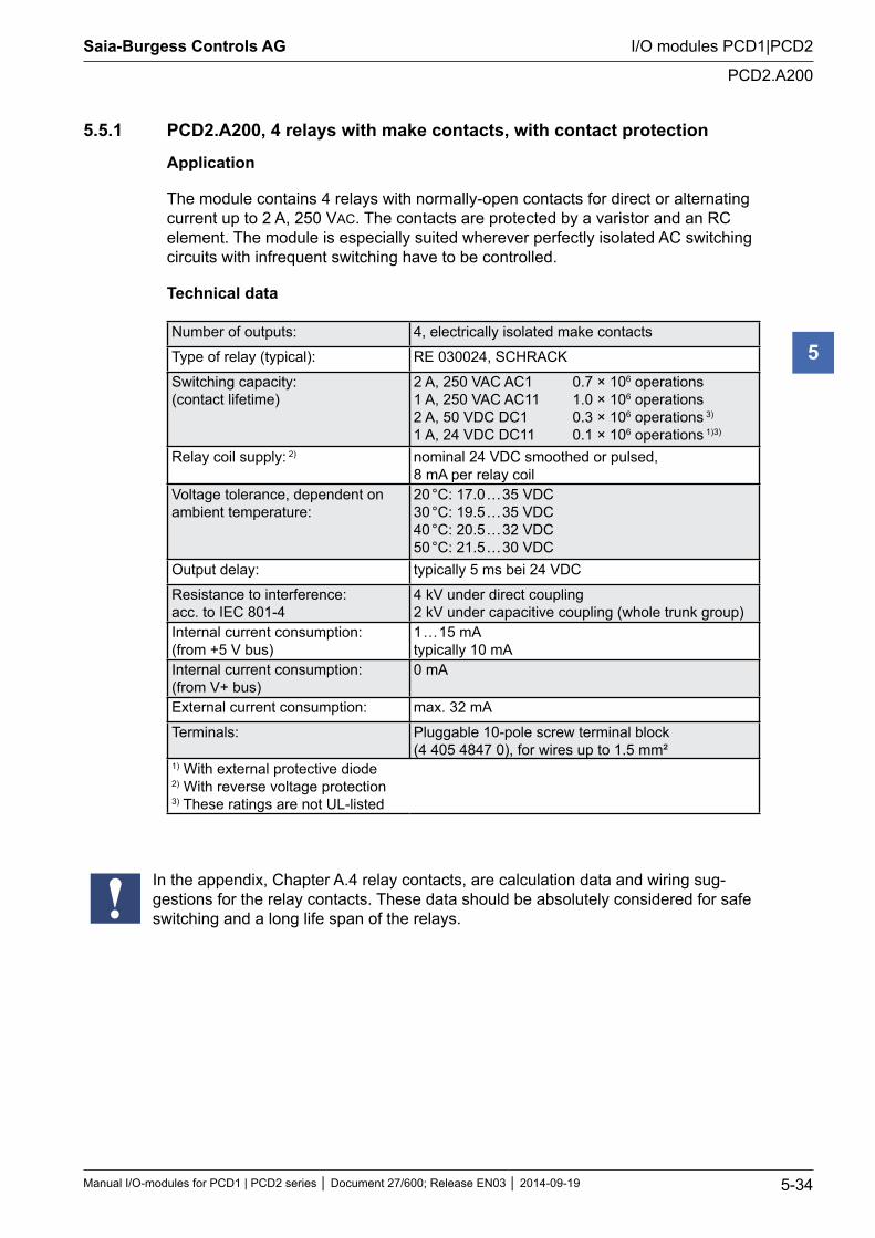
5.5.1 PCD2.A200, 4 relays with make contacts, with contact protection
Application
The module contains 4 relays with normally-open contacts for direct or alternating current up to 2 A, 250 VAC. The contacts are protected by a varistor and an RC element. The module is especially suited wherever perfectly isolated AC switching circuits with infrequent switching have to be controlled.
Technical data
Number of outputs: 4, electrically isolated make contacts
Type of relay (typical): RE 030024, SCHRACK
Switching capacity: (contact lifetime)
2 A, 250 VAC AC1 0.7 × 10⁶ operations 1 A, 250 VAC AC11 1.0 × 10⁶ operations 2 A, 50 VDC DC1 0.3 × 10⁶ operations 3) 1 A, 24 VDC DC11 0.1 × 10⁶ operations 1)3)
Relay coil supply: 2) nominal 24 VDC smoothed or pulsed, 8 mA per relay coil
Voltage tolerance, dependent on ambient temperature:
20 °C: 17.0 … 35 VDC 30 °C: 19.5 … 35 VDC 40 °C: 20.5 … 32 VDC 50 °C: 21.5 … 30 VDC
Output delay: typically 5 ms bei 24 VDC
Resistance to interference: acc. to IEC 801-4
4 kV under direct coupling 2 kV under capacitive coupling (whole trunk group)
Internal current consumption: (from +5 V bus)
1 … 15 mA typically 10 mA
Internal current consumption: (from V+ bus)
0 mA
External current consumption: max. 32 mA
Terminals: Pluggable 10-pole screw terminal block (4 405 4847 0), for wires up to 1.5 mm²
1) With external protective diode 2) With reverse voltage protection 3) These ratings are not UL-listed
In the appendix, Chapter A.4 relay contacts, are calculation data and wiring sug-gestions for the relay contacts. These data should be absolutely considered for safe switching and a long life span of the relays.
Saia-Burgess Controls AG
Manual I/O-modules for PCD1 | PCD2 series Document 27/600; Release EN03 2014-09-19 5-35
I/O modules PCD1|PCD2
PCD2.A200
5
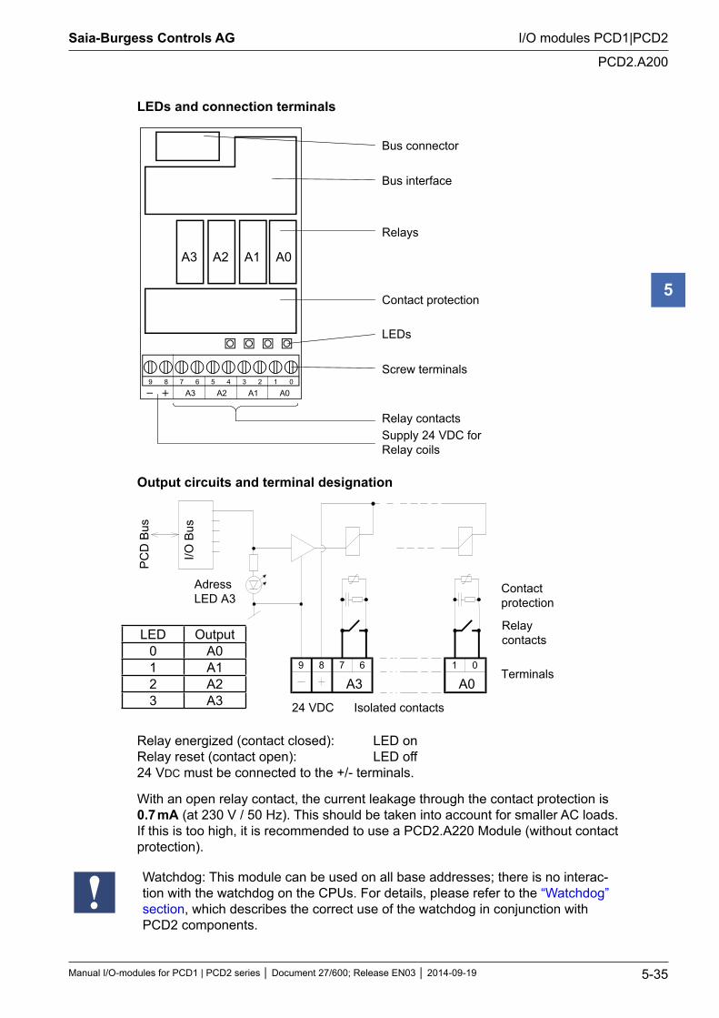
LEDs and connection terminals
Bus connector
Bus interface
Relays
Contact protection
LEDs
Screw terminals
Relay contacts Supply 24 VDC for
Relay coils
9 8 7 6 5 4 3 2 1 0
A0A1A2A3
A0A1A2A3
Output circuits and terminal designation
A00189
A367
I/O B
us
PC
D B
us
Contactprotection
Relaycontacts
Terminals
24 VDC Isolated contacts
AdressLED A3
Relay energized (contact closed): LED on Relay reset (contact open): LED off 24 VDC must be connected to the +/- terminals.
With an open relay contact, the current leakage through the contact protection is 0.7 mA (at 230 V / 50 Hz). This should be taken into account for smaller AC loads. If this is too high, it is recommended to use a PCD2.A220 Module (without contact protection).
Watchdog: This module can be used on all base addresses; there is no interac-tion with the watchdog on the CPUs. For details, please refer to the “Watchdog” section, which describes the correct use of the watchdog in conjunction with PCD2 components.
LED Output0 A01 A12 A23 A3
Saia-Burgess Controls AG
Manual I/O-modules for PCD1 | PCD2 series Document 27/600; Release EN03 2014-09-19 5-36
I/O modules PCD1|PCD2
PCD2.A210
5
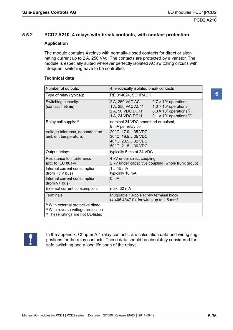
5.5.2 PCD2.A210, 4 relays with break contacts, with contact protection
Application
The module contains 4 relays with normally-closed contacts for direct or alter-nating current up to 2 A, 250 VAC. The contacts are protected by a varistor. The module is especially suited wherever perfectly isolated AC switching circuits with infrequent switching have to be controlled.
Technical data
Number of outputs: 4, electrically isolated break contacts
Type of relay (typical): RE 014024, SCHRACK
Switching capacity: (contact lifetime)
2 A, 250 VAC AC1 0.7 × 10⁶ operations 1 A, 250 VAC AC11 1.0 × 10⁶ operations 2 A, 50 VDC DC11 0.3 × 10⁶ operations 3) 1 A, 24 VDC DC11 0.1 × 10⁶ operations 1)3)
Relay coil supply: 2) nominal 24 VDC smoothed or pulsed, 9 mA per relay coil
Voltage tolerance, dependent on ambient temperature:
20 °C: 17.0 … 35 VDC 30 °C: 19.5 … 35 VDC 40 °C: 20.5 … 32 VDC 50 °C: 21.5 … 30 VDC
Output delay: typically 5 ms at 24 VDC
Resistance to interference: acc. to IEC 801-4
4 kV under direct coupling 2 kV under capacitive coupling (whole trunk group)
Internal current consumption: (from +5 V bus)
1 … 15 mA typically 10 mA
Internal current consumption: (from V+ bus)
0 mA
External current consumption: max. 32 mA
Terminals: Pluggable 10-pole screw terminal block (4 405 4847 0), for wires up to 1.5 mm²
1) With external protective diode 2) With reverse voltage protection 3) These ratings are not UL-listed
In the appendix, Chapter A.4 relay contacts, are calculation data and wiring sug-gestions for the relay contacts. These data should be absolutely considered for safe switching and a long life span of the relays.
Saia-Burgess Controls AG
Manual I/O-modules for PCD1 | PCD2 series Document 27/600; Release EN03 2014-09-19 5-37
I/O modules PCD1|PCD2
PCD2.A210
5
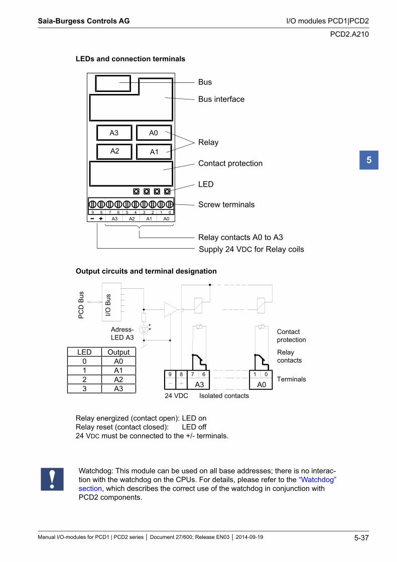
LEDs and connection terminals
9 8 7 6 5 4 3 2 1 0 A0 A1 A2 A3
A0
A1 A2
A3
Bus
Bus interface
Relay
Contact protection
LED
Screw terminals
Relay contacts A0 to A3 Supply 24 VDC for Relay coils
Output circuits and terminal designation
A00189
A367
I/O B
us
PC
D B
us
Contactprotection
Relaycontacts
Terminals
24 VDC Isolated contacts
Adress-LED A3
Relay energized (contact open): LED on Relay reset (contact closed): LED off 24 VDC must be connected to the +/- terminals.
Watchdog: This module can be used on all base addresses; there is no interac-tion with the watchdog on the CPUs. For details, please refer to the “Watchdog” section, which describes the correct use of the watchdog in conjunction with PCD2 components.
LED Output0 A01 A12 A23 A3
Saia-Burgess Controls AG
Manual I/O-modules for PCD1 | PCD2 series Document 27/600; Release EN03 2014-09-19 5-38
I/O modules PCD1|PCD2
PCD2.A220
5
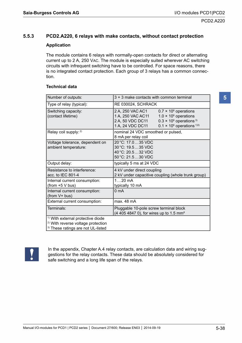
5.5.3 PCD2.A220, 6 relays with make contacts, without contact protection
Application
The module contains 6 relays with normally-open contacts for direct or alternating current up to 2 A, 250 VAC. The module is especially suited wherever AC switching circuits with infrequent switching have to be controlled. For space reasons, there is no integrated contact protection. Each group of 3 relays has a common connec-tion.
Technical data
Number of outputs: 3 + 3 make contacts with common terminal
Type of relay (typical): RE 030024, SCHRACK
Switching capacity: (contact lifetime)
2 A, 250 VAC AC1 0.7 × 10⁶ operations 1 A, 250 VAC AC11 1.0 × 10⁶ operations 2 A, 50 VDC DC11 0.3 × 10⁶ operations 3) 1 A, 24 VDC DC11 0.1 × 10⁶ operations 1)3)
Relay coil supply: 2) nominal 24 VDC smoothed or pulsed, 8 mA per relay coil
Voltage tolerance, dependent on ambient temperature:
20 °C: 17.0 … 35 VDC 30 °C: 19.5 … 35 VDC 40 °C: 20.5 … 32 VDC 50 °C: 21.5 … 30 VDC
Output delay: typically 5 ms at 24 VDC
Resistance to interference: acc. to IEC 801-4
4 kV under direct coupling 2 kV under capacitive coupling (whole trunk group)
Internal current consumption: (from +5 V bus)
1 … 20 mA typically 10 mA
Internal current consumption: (from V+ bus)
0 mA
External current consumption: max. 48 mA
Terminals: Pluggable 10-pole screw terminal block (4 405 4847 0), for wires up to 1.5 mm²
1) With external protective diode 2) With reverse voltage protection 3) These ratings are not UL-listed
In the appendix, Chapter A.4 relay contacts, are calculation data and wiring sug-gestions for the relay contacts. These data should be absolutely considered for safe switching and a long life span of the relays.
Saia-Burgess Controls AG
Manual I/O-modules for PCD1 | PCD2 series Document 27/600; Release EN03 2014-09-19 5-39
I/O modules PCD1|PCD2
PCD2.A220
5
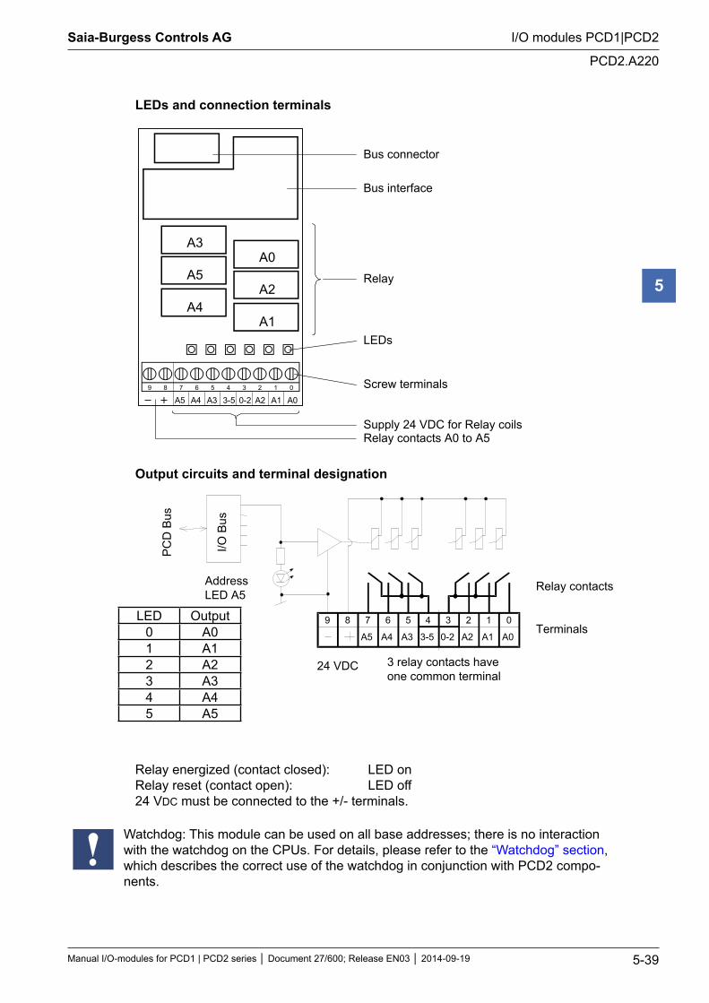
LEDs and connection terminals
Bus connector
Bus interface
Relay
LEDs
Screw terminals
Supply 24 VDC for Relay coils Relay contacts A0 to A5
9 8 7 6 5 4 3 2 1 0
A0A1A20-23-5A3A4A5
A0
A2
A1
A3
A5
A4
Output circuits and terminal designation
89
A4
67
I/O B
us
PC
D B
us
3-5
45
A1
23
A0
01
0-2 A2A3A5
Relay contacts
Terminals
24 VDC 3 relay contacts haveone common terminal
AddressLED A5
Relay energized (contact closed): LED on Relay reset (contact open): LED off 24 VDC must be connected to the +/- terminals.
Watchdog: This module can be used on all base addresses; there is no interaction with the watchdog on the CPUs. For details, please refer to the “Watchdog” section, which describes the correct use of the watchdog in conjunction with PCD2 compo-nents.
LED Output0 A01 A12 A23 A34 A45 A5
Saia-Burgess Controls AG
Manual I/O-modules for PCD1 | PCD2 series Document 27/600; Release EN03 2014-09-19 5-40
I/O modules PCD1|PCD2
PCD2.A250
5
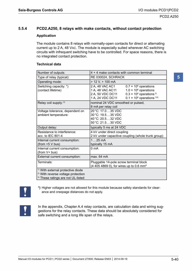
5.5.4 PCD2.A250, 8 relays with make contacts, without contact protection
Application
The module contains 8 relays with normally-open contacts for direct or alternating current up to 2 A, 48 VAC. The module is especially suited wherever AC switching circuits with infrequent switching have to be controlled. For space reasons, there is no integrated contact protection.
Technical data
Number of outputs: 4 + 4 make contacts with common terminalType of relay (typical): RE 030024, SCHRACKOperating mode: > 12 V, > 100 mASwitching capacity: *) (contact lifetime)
2 A, 48 VAC AC1 0.7 × 10⁶ operations 1 A, 48 VAC AC11 1.0 × 10⁶ operations 2 A, 50 VDC DC11 0.3 × 10⁶ operations 3) 1 A, 24 VDC DC11 0.1 × 10⁶ operations 1)3)
Relay coil supply: 2) nominal 24 VDC smoothed or pulsed, 8 mA per relay coil
Voltage tolerance, dependent on ambient temperature:
20 °C: 17.0 … 35 VDC 30 °C: 19.5 … 35 VDC 40 °C: 20.5 … 32 VDC 50 °C: 21.5 … 30 VDC
Output delay: typically 5 ms at 24 VDCResistance to interference: acc. to IEC 801-4
4 kV under direct coupling 2 kV under capacitive coupling (whole trunk group)
Internal current consumption: (from +5 V bus)
1 … 25 mA typically 15 mA
Internal current consumption: (from V+ bus)
0 mA
External current consumption: max. 64 mA
Terminals: Pluggable 14-pole screw terminal block (4 405 4869 0), for wires up to 0.6 mm²
1) With external protective diode 2) With reverse voltage protection 3) These ratings are not UL-listed
*) Higher voltages are not allowed for this module because safety standards for clear-ance and creepage distances do not apply.
In the appendix, Chapter A.4 relay contacts, are calculation data and wiring sug-gestions for the relay contacts. These data should be absolutely considered for safe switching and a long life span of the relays.
Saia-Burgess Controls AG
Manual I/O-modules for PCD1 | PCD2 series Document 27/600; Release EN03 2014-09-19 5-41
I/O modules PCD1|PCD2
PCD2.A250
5
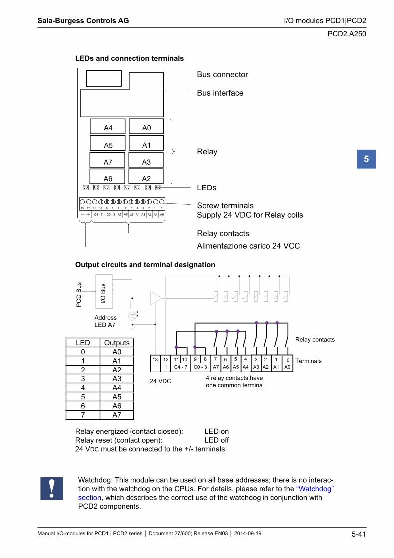
LEDs and connection terminals
A0
A1
A3
A4
A5
A7
A2A6
012345678910111213
A7 A6 A5 A4 A3 A2 A1 A0C4 - 7 C0 - 3
Bus connector
Bus interface
Relay
LEDs
Screw terminals
Relay contacts
Supply 24 VDC for Relay coils
Alimentazione carico 24 VCC
Output circuits and terminal designation
89 67
I/O B
us
PC
D B
us
5A1
23A001
A2
Relay contacts
Terminals
24 VDC 4 relay contacts haveone common terminal
AddressLED A7
10111213 4A3A4A5A6A7C4 - 7 C0 - 3
Relay energized (contact closed): LED on Relay reset (contact open): LED off 24 VDC must be connected to the +/- terminals.
Watchdog: This module can be used on all base addresses; there is no interac-tion with the watchdog on the CPUs. For details, please refer to the “Watchdog” section, which describes the correct use of the watchdog in conjunction with PCD2 components.
LED Outputs0 A01 A12 A23 A34 A45 A56 A67 A7
Saia-Burgess Controls AG
Manual I/O-modules for PCD1 | PCD2 series Document 27/600; Release EN03 2014-09-19 5-42
I/O modules PCD1|PCD2
PCD2.A410
5
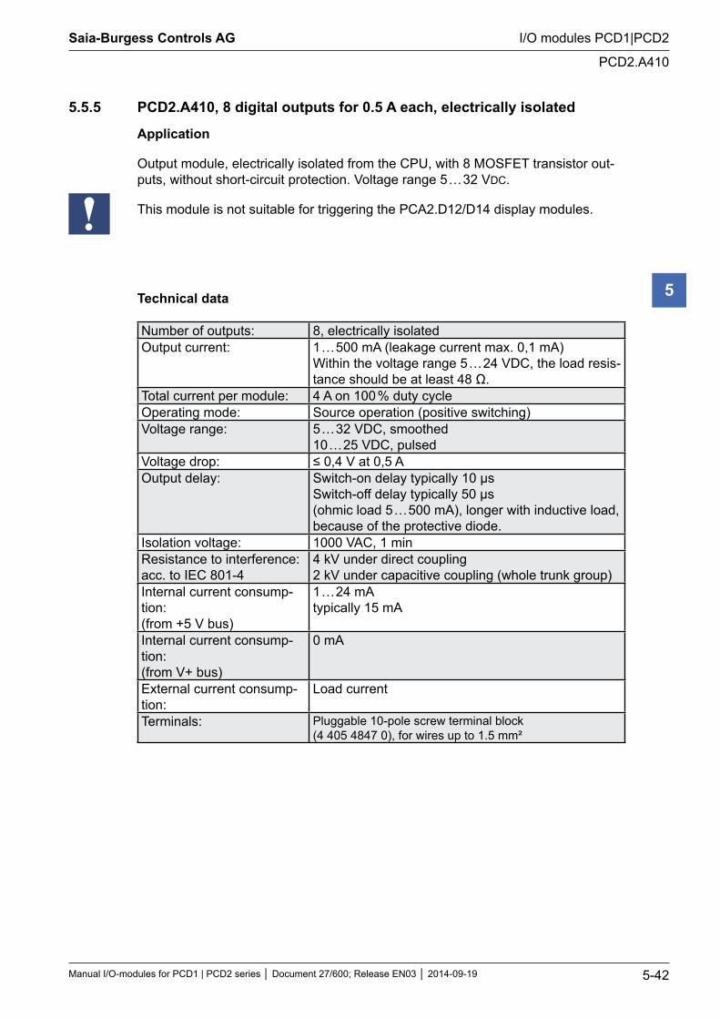
5.5.5 PCD2.A410, 8 digital outputs for 0.5 A each, electrically isolated
Application
Output module, electrically isolated from the CPU, with 8 MOSFET transistor out-puts, without short-circuit protection. Voltage range 5 … 32 VDC.
This module is not suitable for triggering the PCA2.D12/D14 display modules.
Technical data
Number of outputs: 8, electrically isolatedOutput current: 1 … 500 mA (leakage current max. 0,1 mA)
Within the voltage range 5 … 24 VDC, the load resis-tance should be at least 48 Ω.
Total current per module: 4 A on 100 % duty cycleOperating mode: Source operation (positive switching)Voltage range: 5 … 32 VDC, smoothed
10 … 25 VDC, pulsedVoltage drop: ≤ 0,4 V at 0,5 AOutput delay: Switch-on delay typically 10 µs
Switch-off delay typically 50 µs (ohmic load 5 … 500 mA), longer with inductive load, because of the protective diode.
Isolation voltage: 1000 VAC, 1 minResistance to interference: acc. to IEC 801-4
4 kV under direct coupling 2 kV under capacitive coupling (whole trunk group)
Internal current consump-tion: (from +5 V bus)
1 … 24 mA typically 15 mA
Internal current consump-tion: (from V+ bus)
0 mA
External current consump-tion:
Load current
Terminals: Pluggable 10-pole screw terminal block (4 405 4847 0), for wires up to 1.5 mm²
Saia-Burgess Controls AG
Manual I/O-modules for PCD1 | PCD2 series Document 27/600; Release EN03 2014-09-19 5-43
I/O modules PCD1|PCD2
PCD2.A410
5
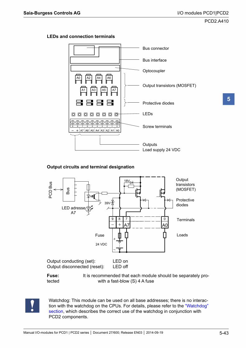
LEDs and connection terminals
Bus connector Bus interface Optocoupler Output transistors (MOSFET) Protective diodes LEDs
Screw terminals
Outputs Load supply 24 VDC
9 8 7 6 5 4 3 2 1 0
A0A1A2A3A4A5
A5A3A1
A4A2A0 A6
A7
A6A7
Output circuits and terminal designation
Bus
PC
D B
us
24 VDC
Fuse
18V
39VLED adresse
A7
Outputtransistors(MOSFET)
Protectivediodes
Terminals
Loads
A0089 7
A7
Output conducting (set): LED on Output disconnected (reset): LED off
Fuse: It is recommended that each module should be separately pro-tected with a fast-blow (S) 4 A fuse
Watchdog: This module can be used on all base addresses; there is no interac-tion with the watchdog on the CPUs. For details, please refer to the “Watchdog” section, which describes the correct use of the watchdog in conjunction with PCD2 components.
Saia-Burgess Controls AG
Manual I/O-modules for PCD1 | PCD2 series Document 27/600; Release EN03 2014-09-19 5-44
I/O modules PCD1|PCD2
Digital combined input and output modules
5
5.6 Digital combined input and output modules
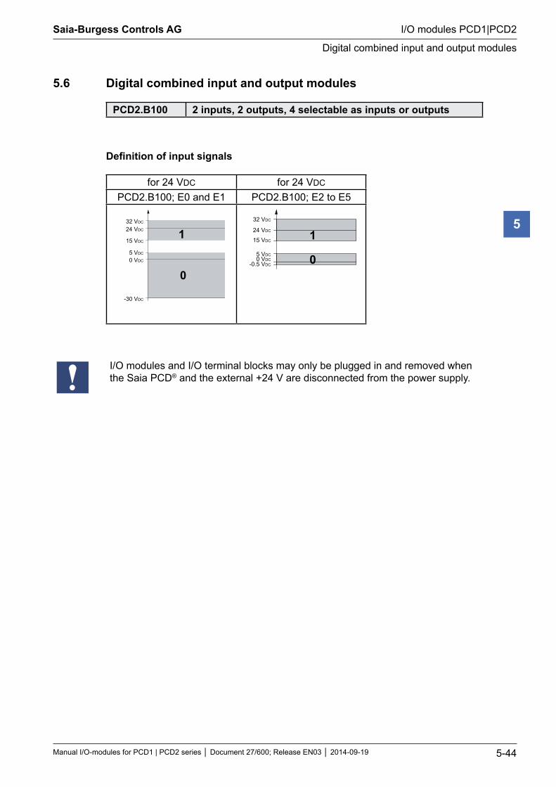
PCD2.B100 2 inputs, 2 outputs, 4 selectable as inputs or outputs
Definition of input signals
for 24 VDC for 24 VDC
PCD2.B100; E0 and E1 PCD2.B100; E2 to E5
32 VDC
24 VDC
15 VDC
0 VDC
5 VDC
-30 VDC
1
0
32 VDC
24 VDC
15 VDC
0 VDC5 VDC
-0.5 VDC
1
0
I/O modules and I/O terminal blocks may only be plugged in and removed when the Saia PCD® and the external +24 V are disconnected from the power supply.
Saia-Burgess Controls AG
Manual I/O-modules for PCD1 | PCD2 series Document 27/600; Release EN03 2014-09-19 5-45
I/O modules PCD1|PCD2
PCD2.B100
5
5.6.1 PCD2.B100, 2 inputs + 2 outputs + 4 digital inputs/outputs (selectable)
Application
Economical combined input/output module with:
2 inputs 24 VDC/8 ms for source operation, electrically connected
2 transistor outputs 0.5 A/5 … 32 VDC, electrically connected, not short circuit protected, and
4 combined inputs/outputs 24 VDC/8 ms or 0.5 A/5 … 32 VDC on common I/O terminals.
Technical data on inputs
Number of inputs: 6 (2 + 4), electrically connected, source operation
Input voltage: 24 VDC smoothed or pulsed2 inputs E0 and E1 low-range: high-range:
-30 … +5 V +15 … +32 V
4 inputs E/A2 … E/A5 low-range: high-range:
-0.5 … +5 V *) +15 … +32 V
All 6 inputs: low-high switching threshold: high-low switching threshold: hysteresis: input current (24 VDC): switching delay 0-1 (24 VDC): switching delay 1-0 (24 VDC):
13 V typically 6 V typically 7 V typically 7 mA typically 8 ms typically 8 ms typically
*) Negative voltage is restricted by the protective diode (Imax = 0.5 A)
Technical data on outputs
Number of outputs: 6 (2 + 4) electrically connected, source operation not short circuit protected
Current: 5 … 500 mA steady loadVoltage range: 5 … 32 VDC *)Voltage drop: < 0.3 V at 500 mA for A6 and A7
< 0.7 V at 500 mA for E/A2 … E/A5Total current per module: 3 A steady loadSwitch-on delay: 10 µs typicallySwitch-off delay: 50 µs typically (100 µs max.), (ohmic load
5 … 500 mA), longer for inductive load because of protective diode.
*) If it is intended to read the status of a combined output, the external voltage must be at least 17 VDC, as both the status and the LED are displayed via the input.
Saia-Burgess Controls AG
Manual I/O-modules for PCD1 | PCD2 series Document 27/600; Release EN03 2014-09-19 5-46
I/O modules PCD1|PCD2
PCD2.B100
5
General technical data on inputs and outputs
Resistance to interference: acc. to IEC 801-4
4 kV under direct coupling 2 kV under capacitive coupling (whole trunk group)
Internal current consumption: (from +5 V bus)
1 … 25 mA typically 15 mA
Internal current consumption: (from V+ bus)
0 mA
External current consumption: Load currentTerminals: Pluggable 10-pole screw terminal block
(4 405 4847 0), for wires up to 1.5 mm²
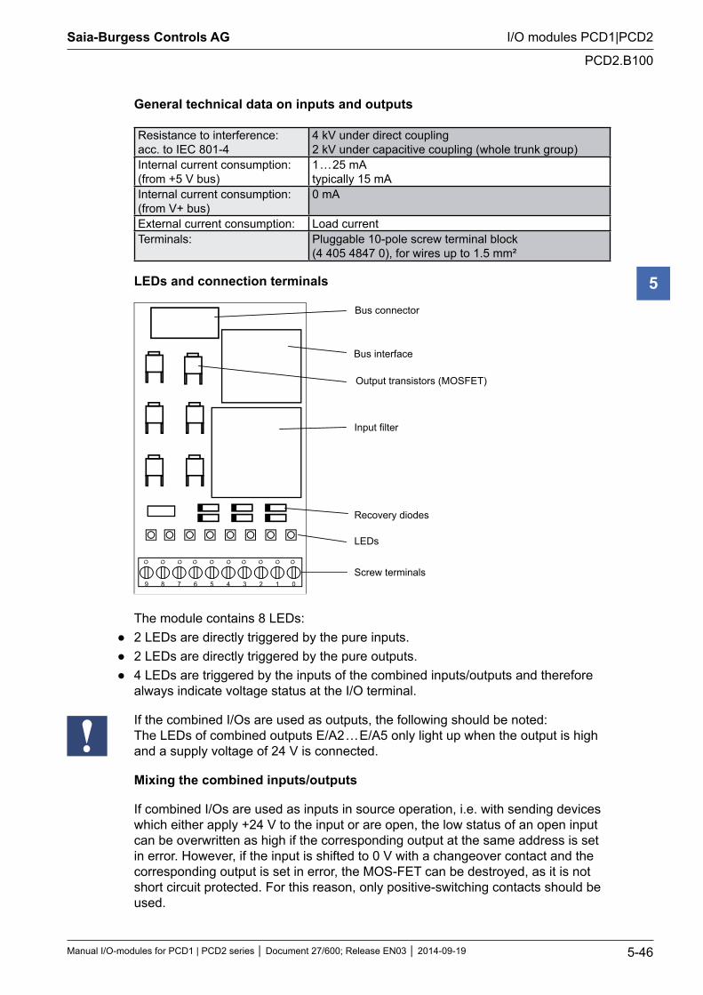
LEDs and connection terminals
Input filter
Recovery diodes
LEDs
Screw terminals 9 8 7 6 5 4 3 2 1 0
Bus connector
Bus interface
Output transistors (MOSFET)
The module contains 8 LEDs: 2 LEDs are directly triggered by the pure inputs. 2 LEDs are directly triggered by the pure outputs. 4 LEDs are triggered by the inputs of the combined inputs/outputs and therefore
always indicate voltage status at the I/O terminal.
If the combined I/Os are used as outputs, the following should be noted: The LEDs of combined outputs E/A2 … E/A5 only light up when the output is high and a supply voltage of 24 V is connected.
Mixing the combined inputs/outputs
If combined I/Os are used as inputs in source operation, i.e. with sending devices which either apply +24 V to the input or are open, the low status of an open input can be overwritten as high if the corresponding output at the same address is set in error. However, if the input is shifted to 0 V with a changeover contact and the corresponding output is set in error, the MOS-FET can be destroyed, as it is not short circuit protected. For this reason, only positive-switching contacts should be used.
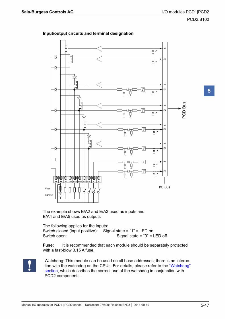
Saia-Burgess Controls AG
Manual I/O-modules for PCD1 | PCD2 series Document 27/600; Release EN03 2014-09-19 5-47
I/O modules PCD1|PCD2
PCD2.B100
5
Input/output circuits and terminal designation
E/A5 E/A4 E/A3 E/A2 E1 E0A6A7
E1
E4
A4
A7
A6
E3
A3
A5
E0
E5
E3
A2
E2
I/O BusP
CD
Bus
24 VDC
Fuse
The example shows E/A2 and E/A3 used as inputs and E/A4 and E/A5 used as outputs
The following applies for the inputs: Switch closed (input positive): Signal state = “1” = LED on Switch open: Signal state = “0” = LED off
Fuse: It is recommended that each module should be separately protected with a fast-blow 3.15 A fuse.
Watchdog: This module can be used on all base addresses; there is no interac-tion with the watchdog on the CPUs. For details, please refer to the “Watchdog” section, which describes the correct use of the watchdog in conjunction with PCD2 components.
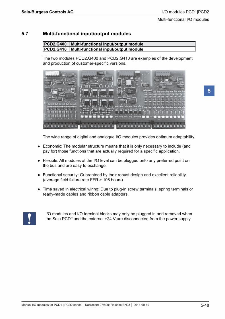
Saia-Burgess Controls AG
Manual I/O-modules for PCD1 | PCD2 series Document 27/600; Release EN03 2014-09-19 5-48
I/O modules PCD1|PCD2
Multi-functional I/O modules
5
5.7 Multi-functional input/output modules
PCD2.G400 Multi-functional input/output modulePCD2.G410 Multi-functional input/output module
The two modules PCD2.G400 and PCD2.G410 are examples of the development and production of customer-specific versions.
The wide range of digital and analogue I/O modules provides optimum adaptability.
Economic: The modular structure means that it is only necessary to include (and pay for) those functions that are actually required for a specific application.
Flexible: All modules at the I/O level can be plugged onto any preferred point on the bus and are easy to exchange.
Functional security: Guaranteed by their robust design and excellent reliability (average field failure rate FFR > 106 hours).
Time saved in electrical wiring: Due to plug-in screw terminals, spring terminals or ready-made cables and ribbon cable adapters.
I/O modules and I/O terminal blocks may only be plugged in and removed when the Saia PCD® and the external +24 V are disconnected from the power supply.
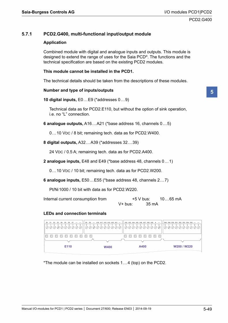
Saia-Burgess Controls AG
Manual I/O-modules for PCD1 | PCD2 series Document 27/600; Release EN03 2014-09-19 5-49
I/O modules PCD1|PCD2
PCD2.G400
5
5.7.1 PCD2.G400, multi-functional input/output module
Application
Combined module with digital and analogue inputs and outputs. This module is designed to extend the range of uses for the Saia PCD®. The functions and the technical specification are based on the existing PCD2 modules.
This module cannot be installed in the PCD1.
The technical details should be taken from the descriptions of these modules.
Number and type of inputs/outputs
10 digital inputs, E0 … E9 (*addresses 0 … 9)
Technical data as for PCD2.E110, but without the option of sink operation, i.e. no “L” connection.
6 analogue outputs, A16 … A21 (*base address 16, channels 0 … 5)
0 … 10 VDC / 8 bit; remaining tech. data as for PCD2.W400.
8 digital outputs, A32 … A39 (*addresses 32 … 39)
24 VDC / 0.5 A; remaining tech. data as for PCD2.A400.
2 analogue inputs, E48 and E49 (*base address 48, channels 0 … 1)
0 … 10 VDC / 10 bit; remaining tech. data as for PCD2.W200.
6 analogue inputs, E50 … E55 (*base address 48, channels 2 … 7)
Pt/Ni 1000 / 10 bit with data as for PCD2.W220.
Internal current consumption from +5 V bus: 10 … 65 mA V+ bus: 35 mA
LEDs and connection terminals
0 1 2 3 4 5 6 7 8 9 0 1 2 3 4 5 6 7 8 9 0 1 2 3 4 5 6 7 8 9 0 1 2 3 4 5 6 7 8 9
E0 E1 E2 E3 E4 E5 E6 E7 ---- ---- E8 E9 A16---- A17 A18 A19 A20 A21 ---- A32 A33 A34 A35 A36 A37 A38 ---- +A39 E48 E49 E50 E51 E52 E53 E54 E55 ---- ----
E110 W400 A400 W200 / W220
*The module can be installed on sockets 1 … 4 (top) on the PCD2.
Saia-Burgess Controls AG
Manual I/O-modules for PCD1 | PCD2 series Document 27/600; Release EN03 2014-09-19 5-50
I/O modules PCD1|PCD2
PCD2.G410
5
5.7.2 PCD2.G410, multi-functional I/O module with elect. isolated digital I/O
Application
Combined module with digital and analogue inputs and outputs. This module is designed to extend the range of uses for the Saia PCD®. The functions and the technical specification are based on the existing PCD2 modules.
This module cannot be installed in the PCD1.
The technical details should be taken from the descriptions of these modules.
Number and type of inputs/outputs
16 digital inputs, electrically isolated, E0 … E15, (addresses 0 … 15).
Tech. data as for PCD2.E610, Source or sink operation selectable via “Q/S” jumper.
4 relay outputs, A16 … A19 (addresses 16 … 19), Each with a changeover contact protected with 2 varistors. Tech. data as for PCD2.A200. The 24 V supply to the relay coils is via the screwless terminals “Uext”, located next to the 4 relays.
4 analogue outputs, with 8 bit resolution, A32 … A35 (base address 32 *, channels 0 … 3) Each channel selectable with “U/I” jumper for voltage 0 … 10 V or current 0 … 20 mA. Tech. data as for PCD2.W410.
4 analogue inputs, with 10 bit resolution, E48 … E51 (base address 48 *, channels 0 … 3)
Each channel can be configured separately with the jumper combinations shown for voltage 0 … 10 V (“U”), current 0 … 20 mA (“I”) or for resistive temperature sensors Pt/Ni 1000 (“T”) for a temperature range from -20 … +100 °C. Tech. data as for PCD2.W2xx.
Internal current consumption from +5 V bus 10 … 50 mA V+ bus 10 … 40 mA
24 V connection (Uext): This is located next to the 4 relays as screwless terminal “Uext”. The 24 V supply is common to the relay coils and the external supply to the analogue outputs.
Current consumption: 9 mA per relay 20 mA per analogue output
* (when the module is installed on sockets 1 … 4 on the PCD2).

Saia-Burgess Controls AG
Manual I/O-modules for PCD1 | PCD2 series Document 27/600; Release EN03 2014-09-19 5-51
I/O modules PCD1|PCD2
PCD2.G410
5
LEDs and connection terminals
The terminal numbering refers to the use of the module on sockets 1 … 4 (top) on the PCD2. If the module is installed on sockets 5 … 8 (bottom), the value 64 must be added to the addresses given. When using the module in the PCD2.C100 expansion housing, the same logic applies, with the value 128 to be added to the ‘top’ and 192 to the ‘bottom’.
0 1 2 3 4 5 6 7 8 9 0 1 2 3 4 5 6 7 8 9 0 1 2 3 4 5 6 7 8 9 0 1 2 3 4 5 6 7 8 9
COM E0 E1 E2 E3 E4 E5 E6 E9 E10 E12 E13 E14 E15A16
---- A32 A33 A34 A35 E48 E49 ----
E610 W410A200 W2..
E7 E8 E11A17 A18 A19
---- E50 E51
Uext
Q S
UI
Jumper Config.
T U I
Factory settings: E0 … E15 Source operation: Q A32 … A35 Voltage: 0 … 10 V “U” E48 … E51 Voltage: 0 … 10 V “U”
Saia-Burgess Controls AG
Manual I/O-modules for PCD1 | PCD2 series Document 27/600; Release EN03 2014-09-19 5-52
I/O modules PCD1|PCD2
Analogue input modules
5
5.8 Analogue input modules
PCD2.W100** 4 analogue inputs 12 Bit, 0 … 10 V, -10 V … +10 V *)PCD2.W105** 4 analogue inputs 12 Bit, 0 … +20 mA, -20 … 0 mA,
-20 mA … +20 mA *)PCD2.W110** 4 analogue inputs 12 bit, Pt 100PCD2.W111** 4 analogue inputs 12 bit, Ni 100PCD2.W112** 4 analogue inputs 12 bit, Pt 1000PCD2.W113** 4 analogue inputs 12 bit, Ni 1000PCD2.W114** 4 analogue inputs 12 Bit, Pt 100, 0 °C … +350 °CPCD2.W200 8 analogue inputs 10 bit, 0 … 10 VPCD2.W210 8 analogue inputs 10 bit, 0..20 mAPCD2.W220 8 analogue inputs 10 bit, Pt/Ni 1000PCD2.W220Z02 8 analogue inputs 10 bit, NTC 10PCD2.W220Z12 8 analogue inputs 10 bit, 4 × 0 … 10 V, 4 × Pt/Ni 1000PCD2.W300 8 analogue inputs 12 bit, 0 … 10 VPCD2.W310 8 analogue inputs 12 bit, 0 … 20 mAPCD2.W340 8 analogue inputs 12 bit, 0 … 10 V, 0 … 20 mA, Pt/Ni 1000 *)PCD2.W350 8 analogue inputs 12 bit, Pt/Ni 100PCD2.W360 8 analogue inputs 12 bit, resolution ‹ 0.1 °C, Pt 1000
*) jumper selectable
**) no longer available
I/O modules and I/O terminal blocks may only be plugged in and removed when the Saia PCD® and the external +24 V are disconnected from the power supply.
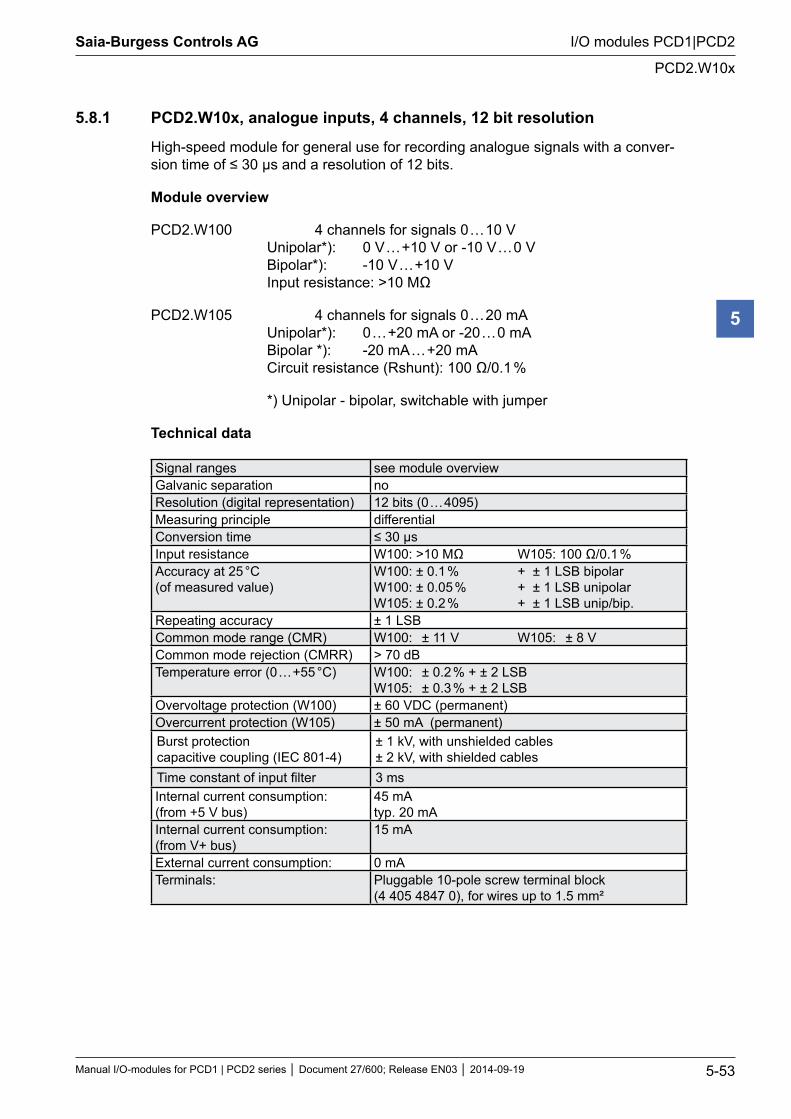
Saia-Burgess Controls AG
Manual I/O-modules for PCD1 | PCD2 series Document 27/600; Release EN03 2014-09-19 5-53
I/O modules PCD1|PCD2
PCD2.W10x
5
5.8.1 PCD2.W10x, analogue inputs, 4 channels, 12 bit resolution
High-speed module for general use for recording analogue signals with a conver-sion time of ≤ 30 µs and a resolution of 12 bits.
Module overview
PCD2.W100 4 channels for signals 0 … 10 V Unipolar*): 0 V … +10 V or -10 V … 0 V Bipolar*): -10 V … +10 V Input resistance: >10 MΩ
PCD2.W105 4 channels for signals 0 … 20 mA Unipolar*): 0 … +20 mA or -20 … 0 mA Bipolar *): -20 mA … +20 mA Circuit resistance (Rshunt): 100 Ω/0.1 %
*) Unipolar - bipolar, switchable with jumper
Technical data
Signal ranges see module overviewGalvanic separation noResolution (digital representation) 12 bits (0 … 4095)Measuring principle differentialConversion time ≤ 30 µsInput resistance W100: >10 MΩ W105: 100 Ω/0.1 %Accuracy at 25 °C (of measured value)
W100: ± 0.1 % + ± 1 LSB bipolar W100: ± 0.05 % + ± 1 LSB unipolar W105: ± 0.2 % + ± 1 LSB unip/bip.
Repeating accuracy ± 1 LSBCommon mode range (CMR) W100: ± 11 V W105: ± 8 VCommon mode rejection (CMRR) > 70 dBTemperature error (0 … +55 °C) W100: ± 0.2 % + ± 2 LSB
W105: ± 0.3 % + ± 2 LSBOvervoltage protection (W100) ± 60 VDC (permanent)Overcurrent protection (W105) ± 50 mA (permanent)Burst protection capacitive coupling (IEC 801-4)
± 1 kV, with unshielded cables ± 2 kV, with shielded cables
Time constant of input filter 3 msInternal current consumption: (from +5 V bus)
45 mA typ. 20 mA
Internal current consumption: (from V+ bus)
15 mA
External current consumption: 0 mATerminals: Pluggable 10-pole screw terminal block
(4 405 4847 0), for wires up to 1.5 mm²
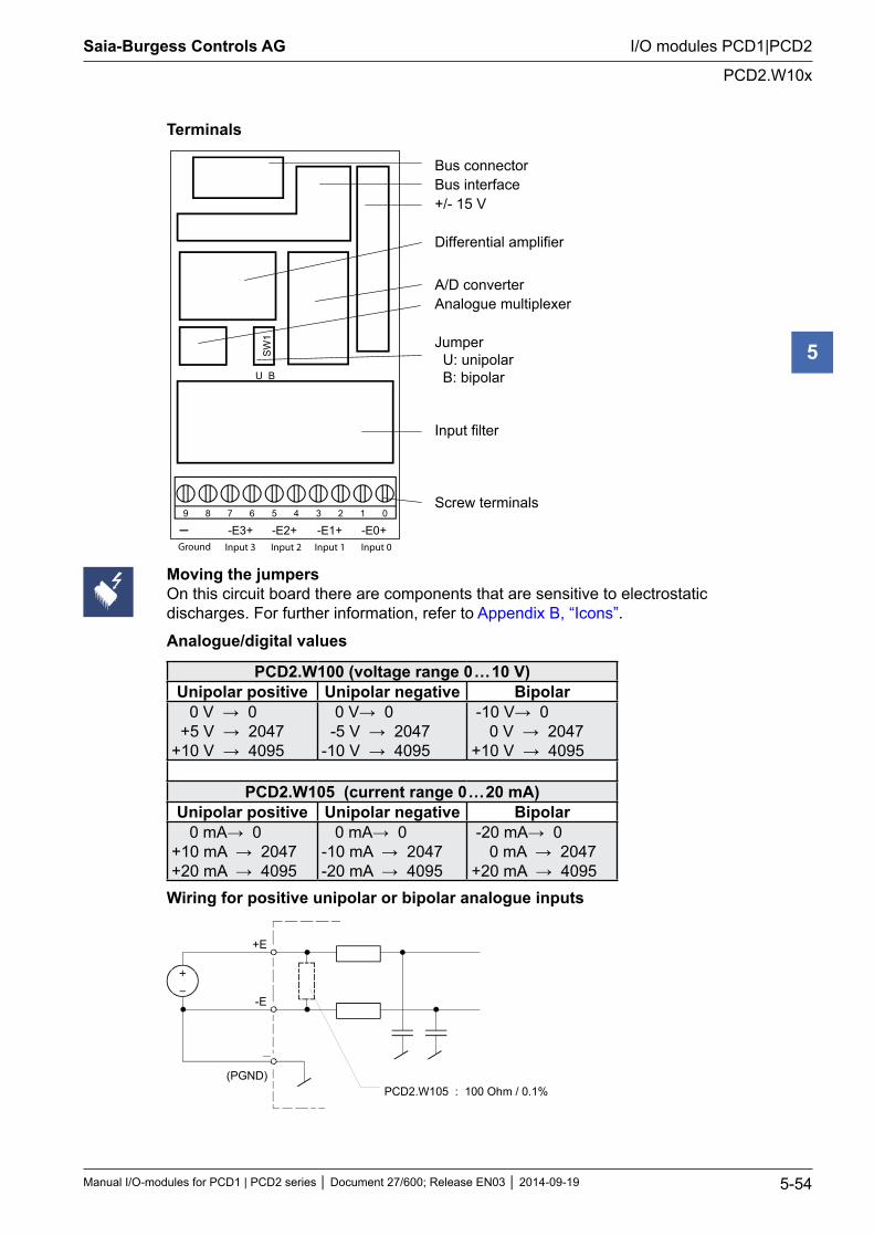
Saia-Burgess Controls AG
Manual I/O-modules for PCD1 | PCD2 series Document 27/600; Release EN03 2014-09-19 5-54
I/O modules PCD1|PCD2
PCD2.W10x
5
Terminals
9 8 7 6 5 4 3 2 1 0
-E0+
U B
SW1
-E1+-E2+-E3+
Bus connector Bus interface +/- 15 V
Differential amplifier
A/D converter Analogue multiplexer
Jumper U: unipolar B: bipolar
Input filter
Screw terminals
Input 1 Input 0Input 2Input 3Ground
Moving the jumpers On this circuit board there are components that are sensitive to electrostatic discharges. For further information, refer to Appendix B, “Icons”.
Analogue/digital values
PCD2.W100 (voltage range 0 … 10 V)Unipolar positive Unipolar negative Bipolar
0 V → 0 +5 V → 2047 +10 V → 4095
0 V→ 0 -5 V → 2047 -10 V → 4095
-10 V→ 0 0 V → 2047 +10 V → 4095
PCD2.W105 (current range 0 … 20 mA)Unipolar positive Unipolar negative Bipolar
0 mA→ 0 +10 mA → 2047 +20 mA → 4095
0 mA→ 0 -10 mA → 2047 -20 mA → 4095
-20 mA→ 0 0 mA → 2047 +20 mA → 4095
Wiring for positive unipolar or bipolar analogue inputs
+E
-E
(PGND)PCD2.W105 : 100 Ohm / 0.1%
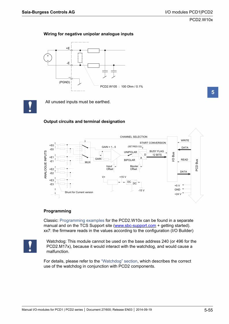
Saia-Burgess Controls AG
Manual I/O-modules for PCD1 | PCD2 series Document 27/600; Release EN03 2014-09-19 5-55
I/O modules PCD1|PCD2
PCD2.W10x
5
Wiring for negative unipolar analogue inputs
+E
-E
(PGND)PCD2.W105 : 100 Ohm / 0.1%
All unused inputs must be earthed.
Output circuits and terminal designation
AN
ALO
GU
E IN
PU
TS
I/O B
us
DATA
READ
WRITE
PC
D B
us
+5 VGND
+24 V
DATA
CHANNEL SELECTION
START CONVERSION
AD 12 BITS
BUSY FLAG
BipolarOffset
UNIPOLAR
BIPOLARGAINMUX
InputOffset
GAIN = 1...5 (SET/RES O2)+E0-E0
+E1-E1
+E2-E2
+E3-E3
0
1
2
3
4
5
6
7
8
9
V+ +15 V
-15 V
DC DC
Shunt for Current version
Programming
Classic: Programming examples for the PCD2.W10x can be found in a separate manual and on the TCS Support site (www.sbc-support.com + getting started). xx7: the firmware reads in the values according to the configuration (I/O Builder)
Watchdog: This module cannot be used on the base address 240 (or 496 for the PCD2.M17x), because it would interact with the watchdog, and would cause a malfunction.
For details, please refer to the “Watchdog” section, which describes the correct use of the watchdog in conjunction with PCD2 components.
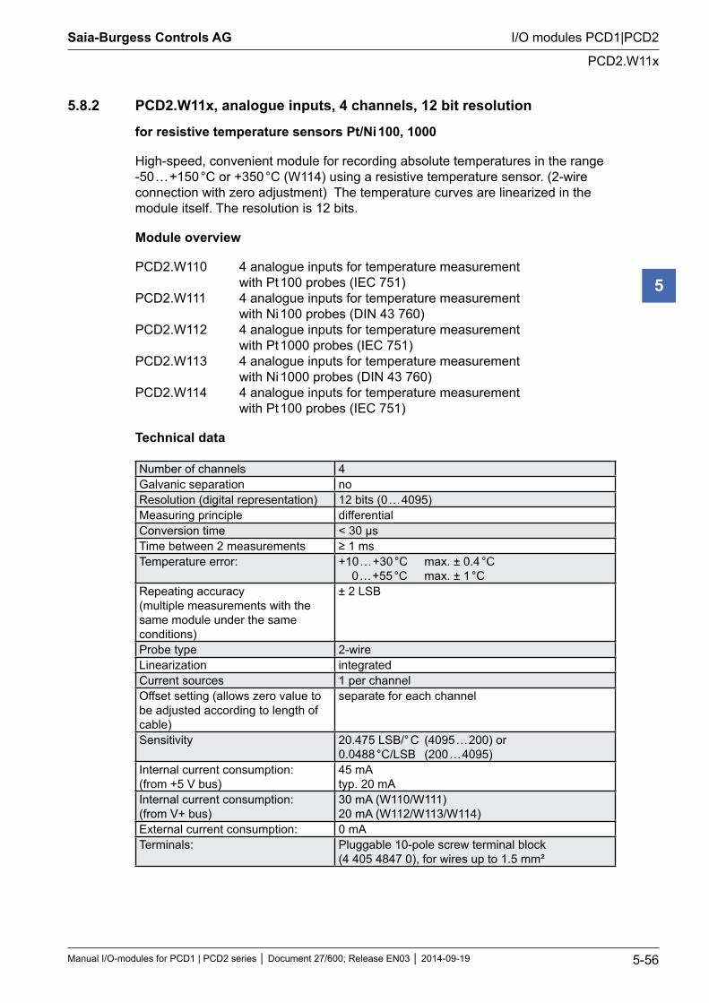
Saia-Burgess Controls AG
Manual I/O-modules for PCD1 | PCD2 series Document 27/600; Release EN03 2014-09-19 5-56
I/O modules PCD1|PCD2
PCD2.W11x
5
5.8.2 PCD2.W11x, analogue inputs, 4 channels, 12 bit resolution
for resistive temperature sensors Pt/Ni 100, 1000
High-speed, convenient module for recording absolute temperatures in the range -50 … +150 °C or +350 °C (W114) using a resistive temperature sensor. (2-wire connection with zero adjustment) The temperature curves are linearized in the module itself. The resolution is 12 bits.
Module overview
PCD2.W110 4 analogue inputs for temperature measurement with Pt 100 probes (IEC 751) PCD2.W111 4 analogue inputs for temperature measurement with Ni 100 probes (DIN 43 760) PCD2.W112 4 analogue inputs for temperature measurement with Pt 1000 probes (IEC 751) PCD2.W113 4 analogue inputs for temperature measurement with Ni 1000 probes (DIN 43 760) PCD2.W114 4 analogue inputs for temperature measurement with Pt 100 probes (IEC 751)
Technical data
Number of channels 4Galvanic separation noResolution (digital representation) 12 bits (0 … 4095)Measuring principle differentialConversion time < 30 µsTime between 2 measurements ≥ 1 msTemperature error: +10 … +30 °C max. ± 0.4 °C
0 … +55 °C max. ± 1 °CRepeating accuracy (multiple measurements with the same module under the same conditions)
± 2 LSB
Probe type 2-wireLinearization integratedCurrent sources 1 per channelOffset setting (allows zero value to be adjusted according to length of cable)
separate for each channel
Sensitivity 20.475 LSB/° C (4095 … 200) or 0.0488 °C/LSB (200 … 4095)
Internal current consumption: (from +5 V bus)
45 mA typ. 20 mA
Internal current consumption: (from V+ bus)
30 mA (W110/W111) 20 mA (W112/W113/W114)
External current consumption: 0 mATerminals: Pluggable 10-pole screw terminal block
(4 405 4847 0), for wires up to 1.5 mm²
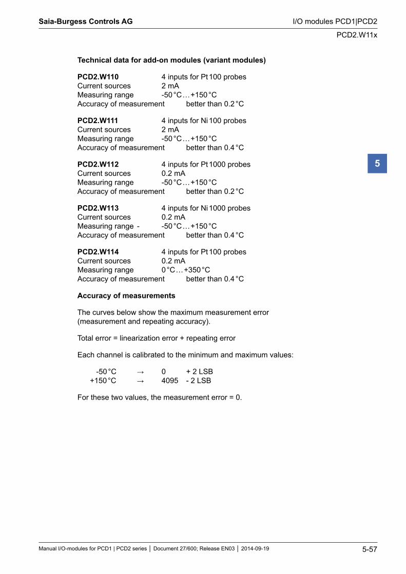
Saia-Burgess Controls AG
Manual I/O-modules for PCD1 | PCD2 series Document 27/600; Release EN03 2014-09-19 5-57
I/O modules PCD1|PCD2
PCD2.W11x
5
Technical data for add-on modules (variant modules)
PCD2.W110 4 inputs for Pt 100 probes Current sources 2 mA Measuring range -50 °C … +150 °C Accuracy of measurement better than 0.2 °C
PCD2.W111 4 inputs for Ni 100 probes Current sources 2 mA Measuring range -50 °C … +150 °C Accuracy of measurement better than 0.4 °C
PCD2.W112 4 inputs for Pt 1000 probes Current sources 0.2 mA Measuring range -50 °C … +150 °C Accuracy of measurement better than 0.2 °C
PCD2.W113 4 inputs for Ni 1000 probes Current sources 0.2 mA Measuring range - -50 °C … +150 °C Accuracy of measurement better than 0.4 °C
PCD2.W114 4 inputs for Pt 100 probes Current sources 0.2 mA Measuring range 0 °C … +350 °C Accuracy of measurement better than 0.4 °C
Accuracy of measurements
The curves below show the maximum measurement error (measurement and repeating accuracy).
Total error = linearization error + repeating error
Each channel is calibrated to the minimum and maximum values:
-50 °C → 0 + 2 LSB +150 °C → 4095 - 2 LSB
For these two values, the measurement error = 0.
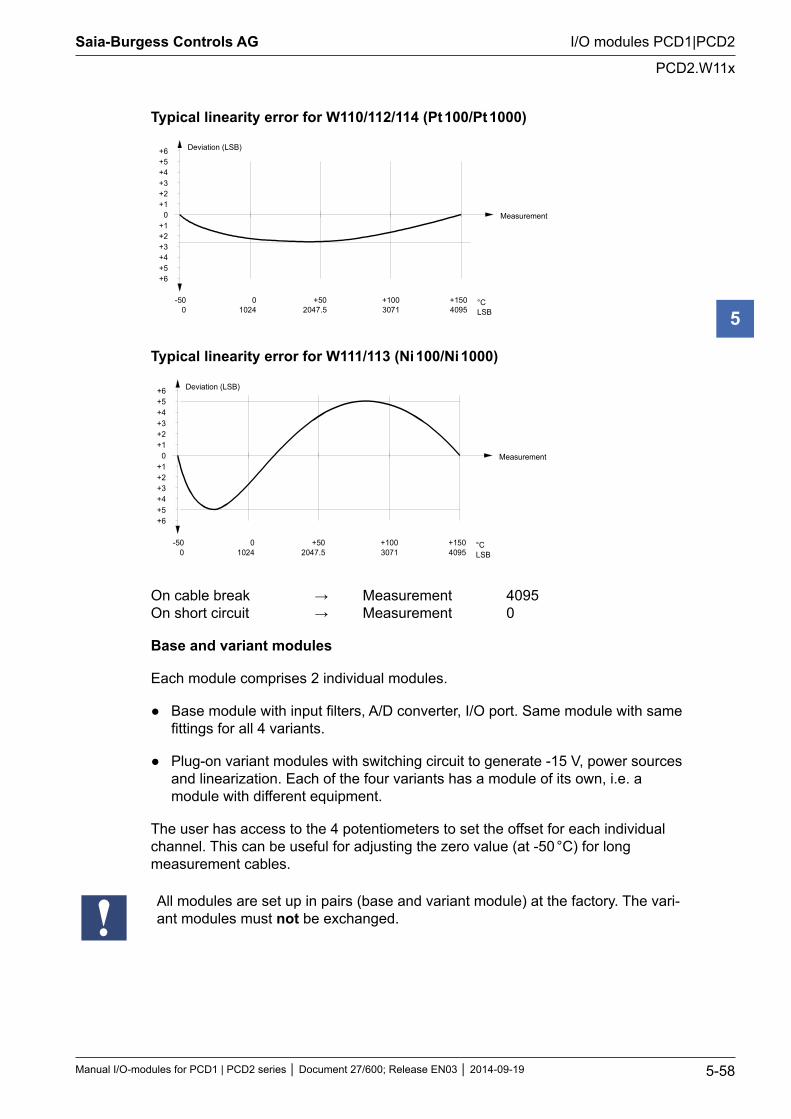
Saia-Burgess Controls AG
Manual I/O-modules for PCD1 | PCD2 series Document 27/600; Release EN03 2014-09-19 5-58
I/O modules PCD1|PCD2
PCD2.W11x
5
Typical linearity error for W110/112/114 (Pt 100/Pt 1000)
-500
01024
+502047.5
+1003071
+1504095
°CLSB
Measurement
Deviation (LSB)
0+1+2+3+4+5
+1+2+3+4+5
+6
+6
Typical linearity error for W111/113 (Ni 100/Ni 1000)
-500
01024
+502047.5
+1003071
+1504095
°CLSB
Measurement
Deviation (LSB)
0+1+2+3+4+5
+1+2+3+4+5
+6
+6
On cable break → Measurement 4095 On short circuit → Measurement 0
Base and variant modules
Each module comprises 2 individual modules.
Base module with input filters, A/D converter, I/O port. Same module with same fittings for all 4 variants.
Plug-on variant modules with switching circuit to generate -15 V, power sources and linearization. Each of the four variants has a module of its own, i.e. a module with different equipment.
The user has access to the 4 potentiometers to set the offset for each individual channel. This can be useful for adjusting the zero value (at -50 °C) for long measurement cables.
All modules are set up in pairs (base and variant module) at the factory. The vari-ant modules must not be exchanged.
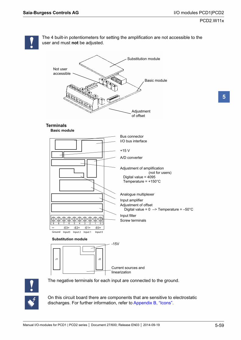
Saia-Burgess Controls AG
Manual I/O-modules for PCD1 | PCD2 series Document 27/600; Release EN03 2014-09-19 5-59
I/O modules PCD1|PCD2
PCD2.W11x
5
The 4 built-in potentiometers for setting the amplification are not accessible to the user and must not be adjusted.
Not useraccessible
Substitution module
Basic module
Adjustmentof offset
Terminals Basic module
Bus connector I/O bus interface
+15 V
A/D converter
Adjustment of amplification (not for users) Digital value = 4095 Temperature = +150°C
Analogue multiplexer Input amplifier Adjustment of offset Digital value = 0 --> Temperature = –50°C
Input filterScrew terminals
9 8 7 6 5 4 3 2 1 0
-E0+-E1+-E2+-E3+
Substitution module -15V
Current sources andlinearization
J1 J2
Input 1 Input 0Input 2Input3Ground
The negative terminals for each input are connected to the ground.
On this circuit board there are components that are sensitive to electrostatic discharges. For further information, refer to Appendix B, “Icons”.
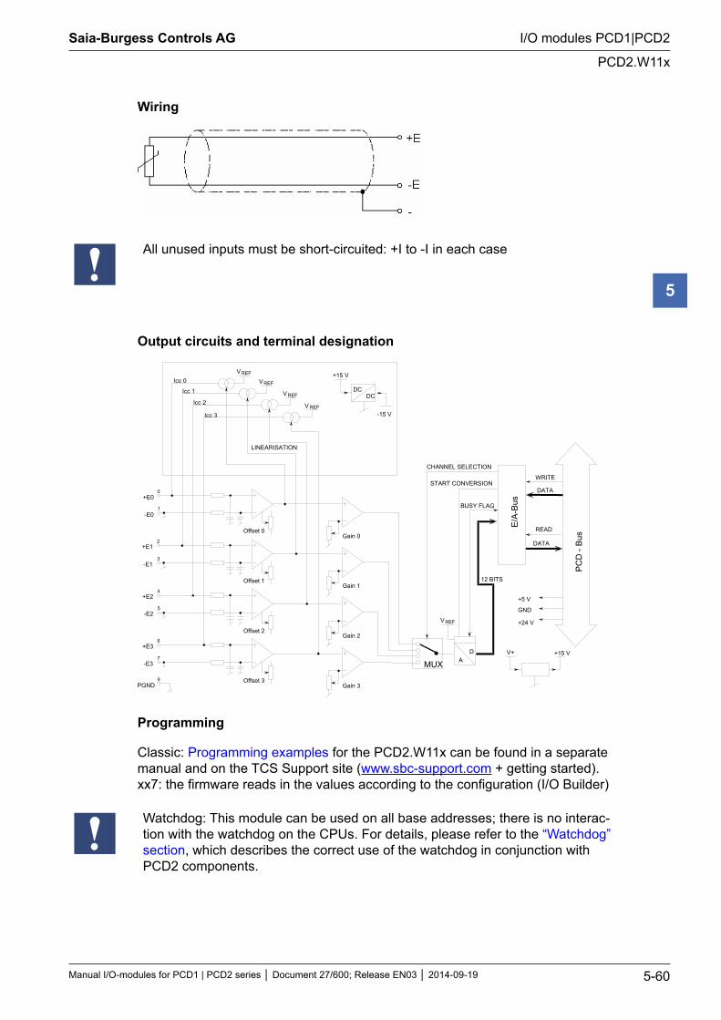
Saia-Burgess Controls AG
Manual I/O-modules for PCD1 | PCD2 series Document 27/600; Release EN03 2014-09-19 5-60
I/O modules PCD1|PCD2
PCD2.W11x
5
Wiring
All unused inputs must be short-circuited: +I to -I in each case
Output circuits and terminal designation
E/A
-Bus
DATA
READ
WRITE
PC
D -
Bus
+5 V
GND
+24 V
DATA
CHANNEL SELECTION
START CONVERSION
AD
12 BITS
BUSY FLAG+E0
-E0
9
V+ +15 V
MUX
Gain 3
Offset 0
Offset 1
Offset 2
Offset 3
V REF
0
1
+E12
-E13
+E24
-E25
+E36
-E37
PGND
Gain 0
V REF
V REF
VREF
V REFIcc 0
Icc 1
Icc 2
Icc 3
LINEARISATION
DCDC
+15 V
-15 V
Gain 1
Gain 2
Programming
Classic: Programming examples for the PCD2.W11x can be found in a separate manual and on the TCS Support site (www.sbc-support.com + getting started). xx7: the firmware reads in the values according to the configuration (I/O Builder)
Watchdog: This module can be used on all base addresses; there is no interac-tion with the watchdog on the CPUs. For details, please refer to the “Watchdog” section, which describes the correct use of the watchdog in conjunction with PCD2 components.
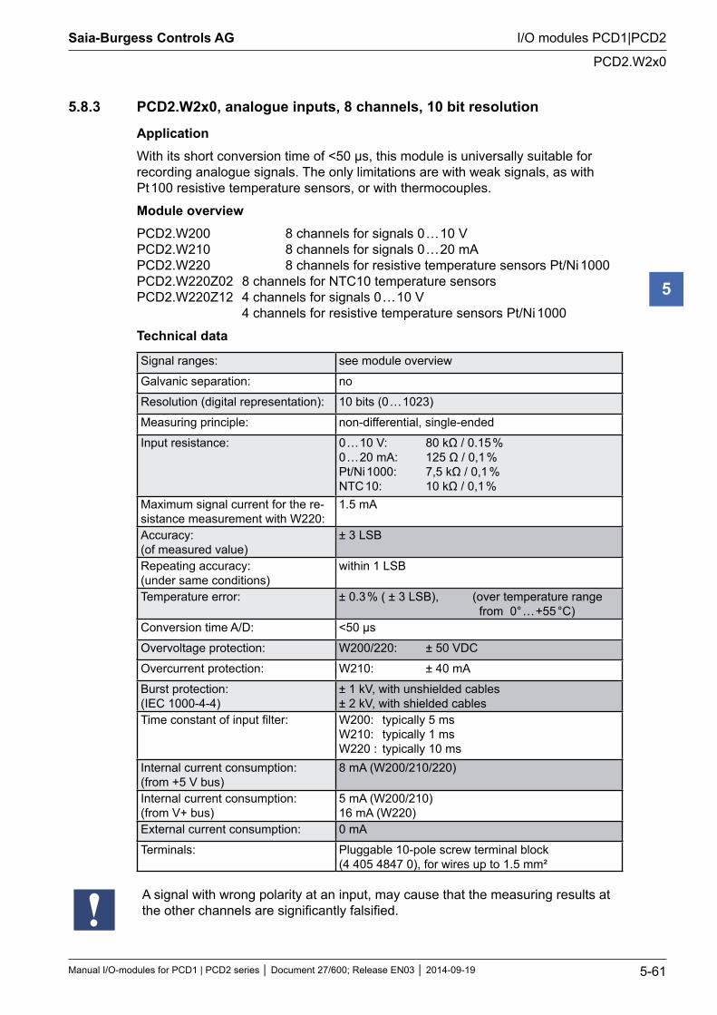
Saia-Burgess Controls AG
Manual I/O-modules for PCD1 | PCD2 series Document 27/600; Release EN03 2014-09-19 5-61
I/O modules PCD1|PCD2
PCD2.W2x0
5
5.8.3 PCD2.W2x0, analogue inputs, 8 channels, 10 bit resolution
ApplicationWith its short conversion time of <50 µs, this module is universally suitable for recording analogue signals. The only limitations are with weak signals, as with Pt 100 resistive temperature sensors, or with thermocouples.
Module overviewPCD2.W200 8 channels for signals 0 … 10 V PCD2.W210 8 channels for signals 0 … 20 mA PCD2.W220 8 channels for resistive temperature sensors Pt/Ni 1000 PCD2.W220Z02 8 channels for NTC10 temperature sensors PCD2.W220Z12 4 channels for signals 0 … 10 V 4 channels for resistive temperature sensors Pt/Ni 1000
Technical data
Signal ranges: see module overview
Galvanic separation: no
Resolution (digital representation): 10 bits (0 … 1023)
Measuring principle: non-differential, single-ended
Input resistance: 0 … 10 V: 80 kΩ / 0.15 % 0 … 20 mA: 125 Ω / 0,1 % Pt/Ni 1000: 7,5 kΩ / 0,1 % NTC 10: 10 kΩ / 0,1 %
Maximum signal current for the re-sistance measurement with W220:
1.5 mA
Accuracy: (of measured value)
± 3 LSB
Repeating accuracy: (under same conditions)
within 1 LSB
Temperature error: ± 0.3 % ( ± 3 LSB), (over temperature range from 0° … +55 °C)
Conversion time A/D: <50 µs
Overvoltage protection: W200/220: ± 50 VDC
Overcurrent protection: W210: ± 40 mA
Burst protection: (IEC 1000-4-4)
± 1 kV, with unshielded cables ± 2 kV, with shielded cables
Time constant of input filter: W200: typically 5 ms W210: typically 1 ms W220 : typically 10 ms
Internal current consumption: (from +5 V bus)
8 mA (W200/210/220)
Internal current consumption: (from V+ bus)
5 mA (W200/210) 16 mA (W220)
External current consumption: 0 mA
Terminals: Pluggable 10-pole screw terminal block (4 405 4847 0), for wires up to 1.5 mm²
A signal with wrong polarity at an input, may cause that the measuring results at the other channels are significantly falsified.

Saia-Burgess Controls AG
Manual I/O-modules for PCD1 | PCD2 series Document 27/600; Release EN03 2014-09-19 5-62
I/O modules PCD1|PCD2
PCD2.W2x0
5
Terminals
Bus connector
Bus interface
Reference voltage (and source)
A/D converter and multiplexer
Input filter
Screw terminals 9 8 7 6 5 4 3 2 1 0
E0123456E7
Digital/analogue values
Input signals and type Digital values PCD2.W200 PCD2.W210 PCD2.W220 Classic xx7 Simatic+ 10.0 V + 20 mA Calculate the
appropriate values with the formulae at the end of this section
1023 1023 27648+ 5.0 V + 10 mA 512 512 13824
+ 4 mA 205 205 55300 V 0 mA 0 0 0– 10.0 V – 20 mA 0 0 0
Connection concept PCD2.W200
9 8 7 6 5 4 3 2 1 0
- E7 E6 E5 E4 E3 E2 E1 E0-
PGND
PCD2/3.W200
Earthing bar
Shield
Sig
nal
sour
ce0…
10 V
Sig
nal
sour
ce0…
10 V
Sig
nal
sour
ce0…
10 V
Sig
nal
sour
ce0…
10 V
max
. 25
cmm
in. 2
.5 m
m2
Power PCD
Shield
Shield
Shield

Saia-Burgess Controls AG
Manual I/O-modules for PCD1 | PCD2 series Document 27/600; Release EN03 2014-09-19 5-63
I/O modules PCD1|PCD2
PCD2.W2x0
5
Connection concept PCD2.W210 for two-wire transducers
E1
E0
GND
PCD2.W210
4...20 mA*
0...20 mA
ϑ
υ
24 VDC
Tempera-ture
Speed
Input filter
+
E2
*4...20 mA over user program
Two-wire transducers (0..20 mA and 4 … 20 mA transmitters) need a 24 VDC sup-ply in the measuring trunk.
Connection concept PCD3.W220 Pt1000 / Ni1000 Connection concept PCD3.W220Z02 NTC10
-
9 8 7 6 5 4 3 2 1 0
- E7 E6 E5 E4 E3 E2 E1 E0PGND
PCD2/3.W220 Pt/Ni 1000
Earthing bar
Shield
Res
ista
nce
ofm
easu
rem
ent
Res
ista
nce
ofm
easu
rem
ent
Res
ista
nce
ofm
easu
rem
ent
Res
ista
nce
ofm
easu
rem
ent
Shield
Shield
Shield
max
. 25
cmm
in. 2
.5 m
m2
Power PCD
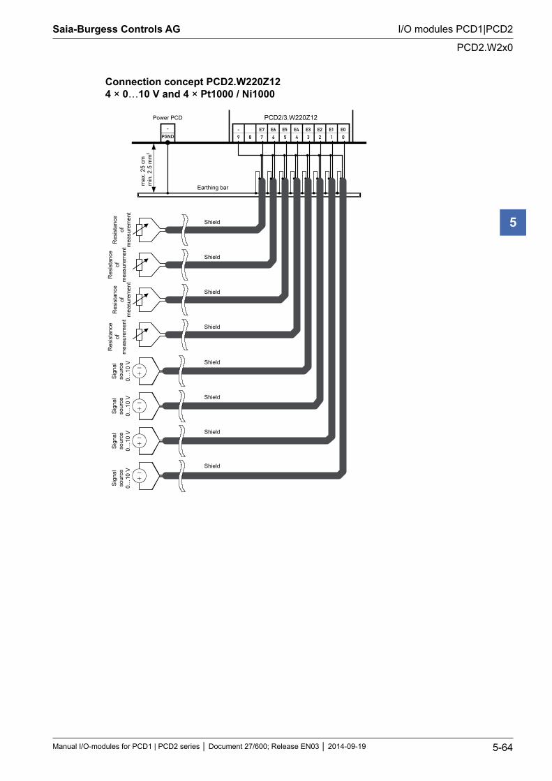
Saia-Burgess Controls AG
Manual I/O-modules for PCD1 | PCD2 series Document 27/600; Release EN03 2014-09-19 5-64
I/O modules PCD1|PCD2
PCD2.W2x0
5
Connection concept PCD2.W220Z12 4 × 0…10 V and 4 × Pt1000 / Ni1000
-
9 8 7 6 5 4 3 2 1 0
- E7 E6 E5 E4 E3 E2 E1 E0PGND
PCD2/3.W220Z12
Earthing bar
Shield
Res
ista
nce
ofm
easu
rem
ent
Res
ista
nce
ofm
easu
rem
ent
Res
ista
nce
ofm
easu
rem
ent
Res
ista
nce
ofm
easu
rem
ent
Shield
Shield
Shield
Shield
Sign
also
urce
0…10
V
Sign
also
urce
0…10
V
Sign
also
urce
0…10
V
Sign
also
urce
0…10
V
Shield
Shield
Shield
Power PCD
max
. 25
cmm
in. 2
.5 m
m2
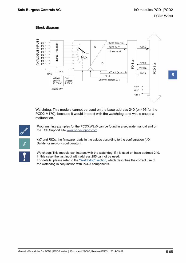
Saia-Burgess Controls AG
Manual I/O-modules for PCD1 | PCD2 series Document 27/600; Release EN03 2014-09-19 5-65
I/O modules PCD1|PCD2
PCD2.W2x0
5
Block diagram
INP
UT
FILT
ERE0
E1E2E3E4E5E6E7A
NA
LOG
UE
INP
UTS
MUX
A
D
BUSY (adr. 15)
DATA OUT
10 bits serial
A/D act. (addr. 15)
Clock
Channel address 0.. 7
I/O B
us
DATA
READ
WRITE
ADDR PC
D B
us
+5 V
GND
+24 V
VoltageSource10.000 V
7K5GND
Ref.Voltage2.500 V
..W220 only
Watchdog: This module cannot be used on the base address 240 (or 496 for the PCD2.M170), because it would interact with the watchdog, and would cause a malfunction.
Programming examples for the PCD3.W2x0 can be found in a separate manual and on the TCS Support site www.sbc-support.com.
xx7 and RIOs: the firmware reads in the values according to the configuration (I/O Builder or network configurator).
Watchdog: This module can interact with the watchdog, if it is used on base address 240. In this case, the last input with address 255 cannot be used. For details, please refer to the "Watchdog" section, which describes the correct use of the watchdog in conjunction with PCD3 components.
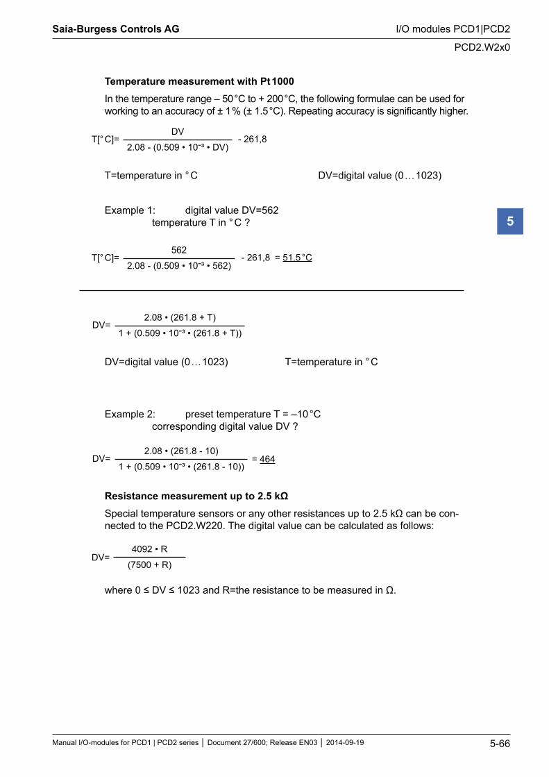
Saia-Burgess Controls AG
Manual I/O-modules for PCD1 | PCD2 series Document 27/600; Release EN03 2014-09-19 5-66
I/O modules PCD1|PCD2
PCD2.W2x0
5
Temperature measurement with Pt 1000In the temperature range – 50 °C to + 200 °C, the following formulae can be used for working to an accuracy of ± 1 % (± 1.5 °C). Repeating accuracy is significantly higher.
T=temperature in ° C DV=digital value (0 … 1023)
Example 1: digital value DV=562 temperature T in ° C ?
DV=digital value (0 … 1023) T=temperature in ° C
Example 2: preset temperature T = –10 °C corresponding digital value DV ?
Resistance measurement up to 2.5 kΩSpecial temperature sensors or any other resistances up to 2.5 kΩ can be con-nected to the PCD2.W220. The digital value can be calculated as follows:
where 0 ≤ DV ≤ 1023 and R=the resistance to be measured in Ω.
DV=4092 • R
(7500 + R)
T[° C]= - 261,8DV
2.08 - (0.509 • 10-³ • DV)
T[° C]= - 261,8562
2.08 - (0.509 • 10-³ • 562)= 51.5 °C
DV=2.08 • (261.8 + T)
1 + (0.509 • 10-³ • (261.8 + T))
DV=2.08 • (261.8 - 10)
1 + (0.509 • 10-³ • (261.8 - 10))= 464
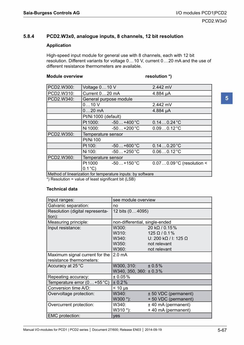
Saia-Burgess Controls AG
Manual I/O-modules for PCD1 | PCD2 series Document 27/600; Release EN03 2014-09-19 5-67
I/O modules PCD1|PCD2
PCD2.W3x0
5
5.8.4 PCD2.W3x0, analogue inputs, 8 channels, 12 bit resolution
Application
High-speed input module for general use with 8 channels, each with 12 bit resolution. Different variants for voltage 0 … 10 V, current 0 … 20 mA and the use of different resistance thermometers are available.
Module overview resolution *)
PCD2.W300: Voltage 0 … 10 V 2.442 mVPCD2.W310: Current 0 … 20 mA 4.884 μAPCD2.W340: General purpose module
0 … 10 V 2.442 mV0 … 20 mA 4.884 μAPt/Ni 1000 (default)Pt 1000: -50 … +400 °C 0.14 … 0.24 °CNi 1000: -50 … +200 °C 0.09 … 0.12 °C
PCD2.W350: Temperature sensorPt/Ni 100Pt 100: -50 … +600 °C 0.14 … 0.20 °CNi 100: -50 … +250 °C 0.06 … 0.12 °C
PCD2.W360: Temperature sensorPt 1000 -50 … +150 °C 0.07 … 0.09 °C (resolution < 0.1 °C)
Method of linearization for temperature inputs: by software*) Resolution = value of least significant bit (LSB)
Technical data
Input ranges: see module overviewGalvanic separation: noResolution (digital representa-tion):
12 bits (0 … 4095)
Measuring principle: non-differential, single-endedInput resistance: W300: 20 kΩ / 0.15 %
W310: 125 Ω / 0.1 % W340: U: 200 kΩ / I: 125 Ω W350: not relevant W360: not relevant
Maximum signal current for the resistance thermometers:
2.0 mA
Accuracy at 25 °C W300, 310: ± 0.5 % W340, 350, 360: ± 0.3 %
Repeating accuracy: ± 0.05 %Temperature error (0 … +55 °C) ± 0.2 %Conversion time A/D: < 10 µsOvervoltage protection: W340: ± 50 VDC (permanent)
W300 *): + 50 VDC (permanent)Overcurrent protection: W340: ± 40 mA (permanent)
W310 *): + 40 mA (permanent)EMC protection: yes
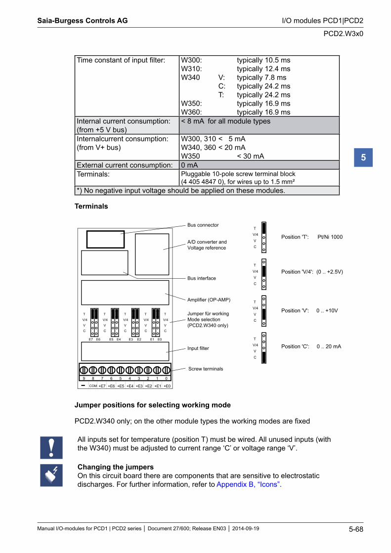
Saia-Burgess Controls AG
Manual I/O-modules for PCD1 | PCD2 series Document 27/600; Release EN03 2014-09-19 5-68
I/O modules PCD1|PCD2
PCD2.W3x0
5
Time constant of input filter: W300: typically 10.5 ms W310: typically 12.4 ms W340 V: typically 7.8 ms C: typically 24.2 ms T: typically 24.2 ms W350: typically 16.9 ms W360: typically 16.9 ms
Internal current consumption: (from +5 V bus)
< 8 mA for all module types
Internalcurrent consumption: (from V+ bus)
W300, 310 < 5 mA W340, 360 < 20 mA W350 < 30 mA
External current consumption: 0 mATerminals: Pluggable 10-pole screw terminal block
(4 405 4847 0), for wires up to 1.5 mm²*) No negative input voltage should be applied on these modules.
Terminals
9 8 7 6 5 4 3 2 1 0
+E6+E7 +E4+E5 +E2+E3 +E0+E1
E7 E6 E5 E4 E3 E2 E1 E0
T
V/4
V
C
T
V/4
V
C
T
V/4
V
C
T
V/4
V
C
T
V/4
V
C
Bus connector
Bus interface
A/D converter andVoltage reference
Amplifier (OP-AMP)
Jumper für workingMode selection(PCD2.W340 only)
Input filter
Screw terminals
COM
T
V/4
V
C
T
V/4
V
C
T
V/4
V
C
T
V/4
V
C
Position 'T': Pt/Ni 1000
Position 'V/4': (0 .. +2.5V)
Position 'V': 0 .. +10V
Position 'C': 0 .. 20 mA
Jumper positions for selecting working mode
PCD2.W340 only; on the other module types the working modes are fixed
All inputs set for temperature (position T) must be wired. All unused inputs (with the W340) must be adjusted to current range ‘C’ or voltage range ‘V’.
Changing the jumpers On this circuit board there are components that are sensitive to electrostatic discharges. For further information, refer to Appendix B, “Icons”.
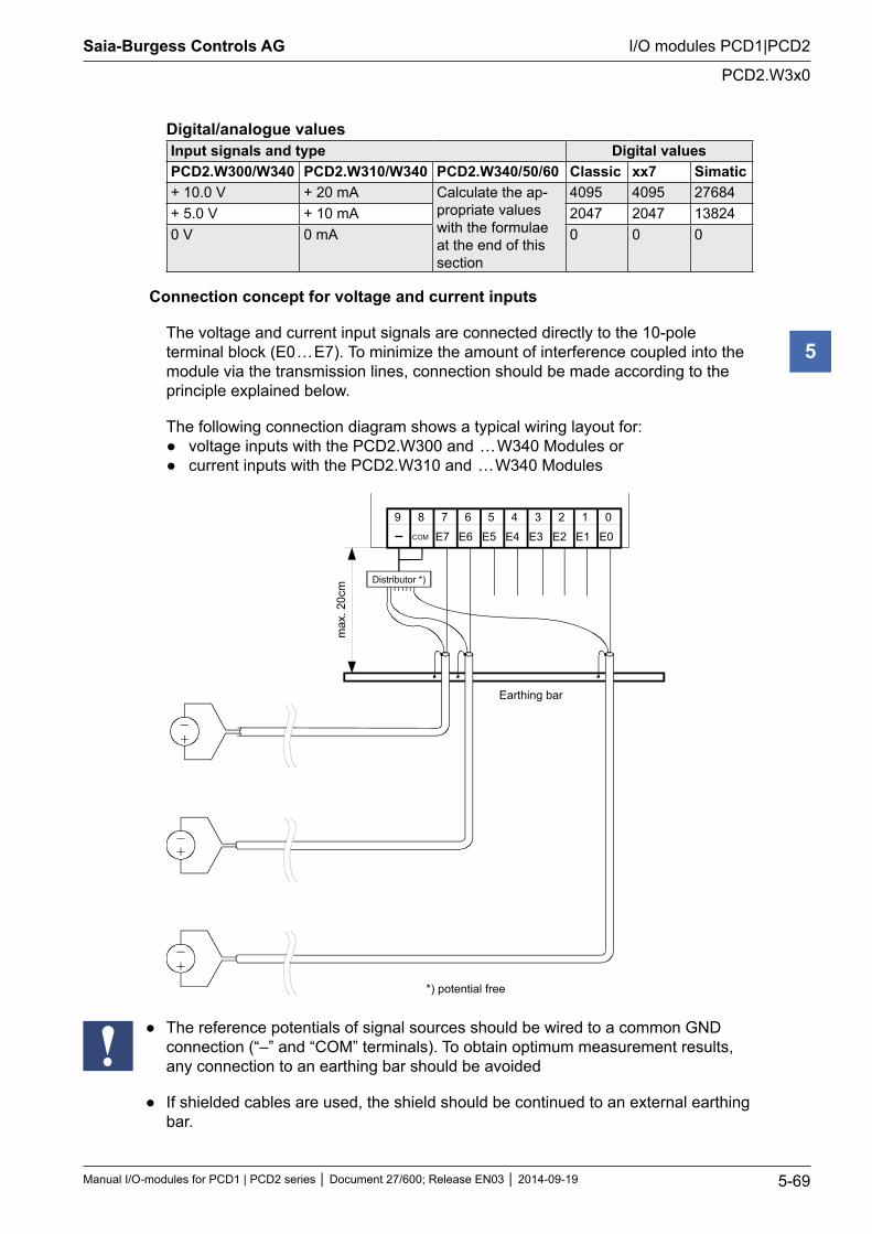
Saia-Burgess Controls AG
Manual I/O-modules for PCD1 | PCD2 series Document 27/600; Release EN03 2014-09-19 5-69
I/O modules PCD1|PCD2
PCD2.W3x0
5
Digital/analogue valuesInput signals and type Digital values PCD2.W300/W340 PCD2.W310/W340 PCD2.W340/50/60 Classic xx7 Simatic+ 10.0 V + 20 mA Calculate the ap-
propriate values with the formulae at the end of this section
4095 4095 27684+ 5.0 V + 10 mA 2047 2047 138240 V 0 mA 0 0 0
Connection concept for voltage and current inputs
The voltage and current input signals are connected directly to the 10-pole terminal block (E0 … E7). To minimize the amount of interference coupled into the module via the transmission lines, connection should be made according to the principle explained below.
The following connection diagram shows a typical wiring layout for: voltage inputs with the PCD2.W300 and … W340 Modules or current inputs with the PCD2.W310 and … W340 Modules
89
E6
67
E4
45
E1
23
E0
01
E3 E2E5E7
Earthing bar
max
. 20c
m
COM
Distributor *)
*) potential free
The reference potentials of signal sources should be wired to a common GND connection (“–” and “COM” terminals). To obtain optimum measurement results, any connection to an earthing bar should be avoided
If shielded cables are used, the shield should be continued to an external earthing bar.
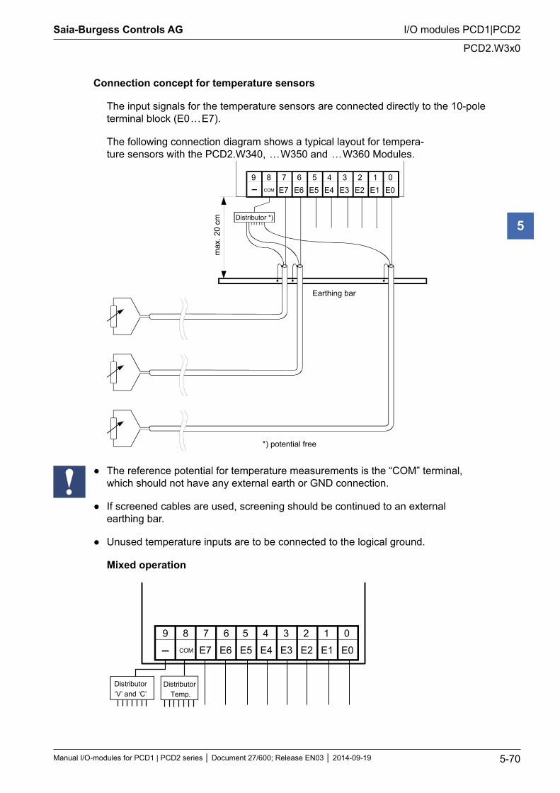
Saia-Burgess Controls AG
Manual I/O-modules for PCD1 | PCD2 series Document 27/600; Release EN03 2014-09-19 5-70
I/O modules PCD1|PCD2
PCD2.W3x0
5
Connection concept for temperature sensors
The input signals for the temperature sensors are connected directly to the 10-pole terminal block (E0 … E7).
The following connection diagram shows a typical layout for tempera-ture sensors with the PCD2.W340, … W350 and … W360 Modules.
89E667
E445
E123
E001
E3 E2E5E7
Earthing bar
max
. 20
cm
COM
Distributor *)
*) potential free
The reference potential for temperature measurements is the “COM” terminal, which should not have any external earth or GND connection.
If screened cables are used, screening should be continued to an external earthing bar.
Unused temperature inputs are to be connected to the logical ground.
Mixed operation
89
E6
67
E4
4 5
E1
2 3
E0
0 1
E3 E2E5E7COM
Distributor‘V’ and ‘C’
Distributor Temp.
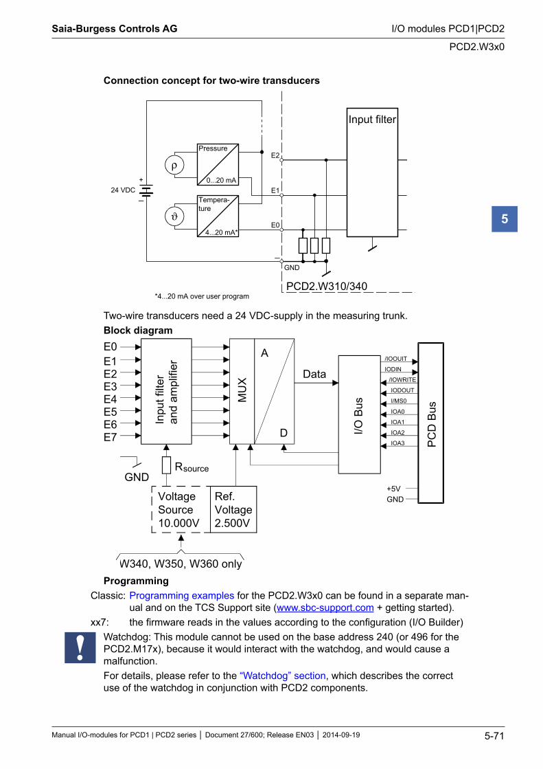
Saia-Burgess Controls AG
Manual I/O-modules for PCD1 | PCD2 series Document 27/600; Release EN03 2014-09-19 5-71
I/O modules PCD1|PCD2
PCD2.W3x0
5
Connection concept for two-wire transducers
E1
E0
GND
PCD2.W310/340
0...20 mA
4...20 mA*
ρ
ϑ
24 VDC
Pressure
Tempera-ture
Input filter
+
E2
*4...20 mA over user program
Two-wire transducers need a 24 VDC-supply in the measuring trunk. Block diagram
E0E1E2E3E4E5E6E7
GNDRsource
VoltageSource10.000V
Ref.Voltage2.500V
Inpu
t filt
eran
d am
plifi
er
MU
X
A
D
DataI/O
Bus
PC
D B
us
+5VGND
/IOOUIT
IODIN
/IOWRITE
IODOUT
I/MS0
IOA0
IOA1
IOA2
IOA3
W340, W350, W360 onlyProgramming
Classic: Programming examples for the PCD2.W3x0 can be found in a separate man-ual and on the TCS Support site (www.sbc-support.com + getting started).
xx7: the firmware reads in the values according to the configuration (I/O Builder) Watchdog: This module cannot be used on the base address 240 (or 496 for the
PCD2.M17x), because it would interact with the watchdog, and would cause a malfunction. For details, please refer to the “Watchdog” section, which describes the correct use of the watchdog in conjunction with PCD2 components.
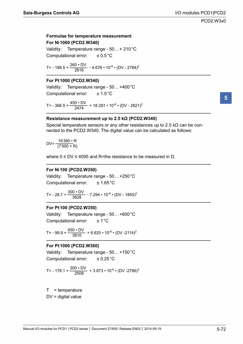
Saia-Burgess Controls AG
Manual I/O-modules for PCD1 | PCD2 series Document 27/600; Release EN03 2014-09-19 5-72
I/O modules PCD1|PCD2
PCD2.W3x0
5
Formulae for temperature measurementFor Ni 1000 (PCD2.W340)Validity: Temperature range - 50 … + 210 °CComputational error: ± 0.5 °C
T= - 188.5 +
260 • DV2616
- 4.676 • 10-6 • (DV - 2784)2
For Pt 1000 (PCD2.W340)Validity: Temperature range - 50 … +400 °CComputational error: ± 1.5 °C
T= - 366.5 +
450 • DV2474
+ 18.291 • 10-6 • (DV - 2821)2
Resistance measurement up to 2.5 kΩ (PCD2.W340)Special temperature sensors or any other resistances up to 2.5 kΩ can be con-nected to the PCD2.W340. The digital value can be calculated as follows:
DV= 16 380 • R(7 500 + R)
where 0 ≤ DV ≤ 4095 and R=the resistance to be measured in Ω.
For Ni 100 (PCD2.W350)Validity: Temperature range - 50 … +250 °CComputational error: ± 1.65 °C
T= - 28.7 +
300 • DV3628
- 7.294 • 10-6 • (DV - 1850)2
For Pt 100 (PCD2.W350)Validity: Temperature range - 50 … +600 °CComputational error: ± 1 °C
T= - 99.9 +
650 • DV3910
+ 6.625 • 10-6 • (DV -2114)2
For Pt 1000 (PCD2.W360)Validity: Temperature range - 50 … +150 °CComputational error: ± 0.25 °C
T= - 178.1 +
200 • DV2509
+ 3.873 • 10-6 • (DV -2786)2
T = temperatureDV = digital value
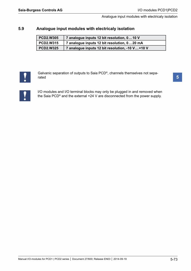
Saia-Burgess Controls AG
Manual I/O-modules for PCD1 | PCD2 series Document 27/600; Release EN03 2014-09-19 5-73
I/O modules PCD1|PCD2
Analogue input modules with electricaly isolation
5
5.9 Analogue input modules with electricaly isolation
PCD2.W305 7 analogue inputs 12 bit resolution, 0 … 10 VPCD2.W315 7 analogue inputs 12 bit resolution, 0 … 20 mAPCD2.W325 7 analogue inputs 12 bit resolution, -10 V … +10 V
Galvanic separation of outputs to Saia PCD®, channels themselves not sepa-rated
I/O modules and I/O terminal blocks may only be plugged in and removed when the Saia PCD® and the external +24 V are disconnected from the power supply.
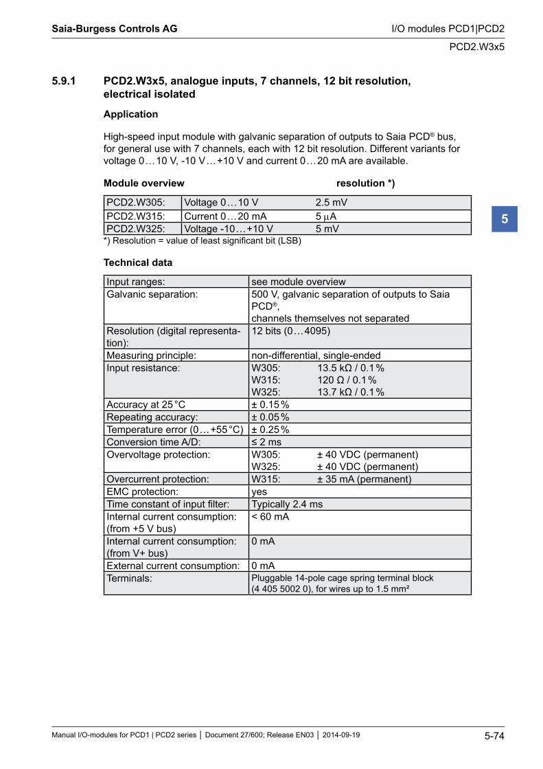
Saia-Burgess Controls AG
Manual I/O-modules for PCD1 | PCD2 series Document 27/600; Release EN03 2014-09-19 5-74
I/O modules PCD1|PCD2
PCD2.W3x5
5
5.9.1 PCD2.W3x5, analogue inputs, 7 channels, 12 bit resolution, electrical isolated
Application
High-speed input module with galvanic separation of outputs to Saia PCD® bus, for general use with 7 channels, each with 12 bit resolution. Different variants for voltage 0 … 10 V, -10 V … +10 V and current 0 … 20 mA are available.
Module overview resolution *)
PCD2.W305: Voltage 0 … 10 V 2.5 mVPCD2.W315: Current 0 … 20 mA 5 µAPCD2.W325: Voltage -10 … +10 V 5 mV
*) Resolution = value of least significant bit (LSB)
Technical data
Input ranges: see module overviewGalvanic separation: 500 V, galvanic separation of outputs to Saia
PCD®, channels themselves not separated
Resolution (digital representa-tion):
12 bits (0 … 4095)
Measuring principle: non-differential, single-endedInput resistance: W305: 13.5 kΩ / 0.1 %
W315: 120 Ω / 0.1 % W325: 13.7 kΩ / 0.1 %
Accuracy at 25 °C ± 0.15 %Repeating accuracy: ± 0.05 %Temperature error (0 … +55 °C) ± 0.25 %Conversion time A/D: ≤ 2 msOvervoltage protection: W305: ± 40 VDC (permanent)
W325: ± 40 VDC (permanent)Overcurrent protection: W315: ± 35 mA (permanent)EMC protection: yesTime constant of input filter: Typically 2.4 msInternal current consumption: (from +5 V bus)
< 60 mA
Internal current consumption: (from V+ bus)
0 mA
External current consumption: 0 mATerminals: Pluggable 14-pole cage spring terminal block
(4 405 5002 0), for wires up to 1.5 mm²
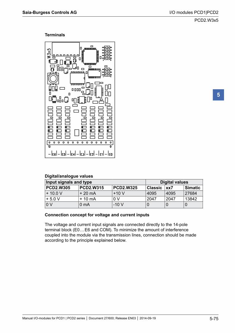
Saia-Burgess Controls AG
Manual I/O-modules for PCD1 | PCD2 series Document 27/600; Release EN03 2014-09-19 5-75
I/O modules PCD1|PCD2
PCD2.W3x5
5
Terminals
Digital/analogue valuesInput signals and type Digital values PCD2.W305 PCD2.W315 PCD2.W325 Classic xx7 Simatic+ 10.0 V + 20 mA +10 V 4095 4095 27684+ 5.0 V + 10 mA 0 V 2047 2047 138420 V 0 mA -10 V 0 0 0
Connection concept for voltage and current inputs
The voltage and current input signals are connected directly to the 14-pole terminal block (E0 … E6 and COM). To minimize the amount of interference coupled into the module via the transmission lines, connection should be made according to the principle explained below.
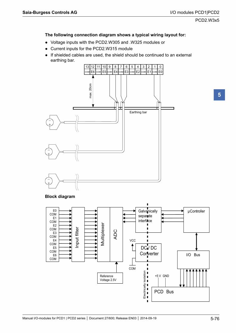
Saia-Burgess Controls AG
Manual I/O-modules for PCD1 | PCD2 series Document 27/600; Release EN03 2014-09-19 5-76
I/O modules PCD1|PCD2
PCD2.W3x5
5
The following connection diagram shows a typical wiring layout for: Voltage inputs with the PCD2.W305 and .W325 modules or Current inputs for the PCD2.W315 module If shielded cables are used, the shield should be continued to an external
earthing bar.
max
.20c
m
E0E1E2E3E4E5E6 COMCOMCOMCOMCOMCOMCOM
012345678910111213
Earthing bar
Block diagram
Inpu
t filt
er
E0 COM
E1 COM
E2 COM
E3 COM
E4 COM
E5 COM
E6 COM
Mul
tiple
xer
AD
C
Reference Voltage 2.5V
μController
PCD Bus
I/O Bus DC / DC Converter
Galvanically separate interface
Ele
ctric
ally
isol
atio
n
VCC
COM
+5 V GND
Saia-Burgess Controls AG
Manual I/O-modules for PCD1 | PCD2 series Document 27/600; Release EN03 2014-09-19 5-77
I/O modules PCD1|PCD2
PCD2.W3x5
5
Programming
Classic: For programming the modules, an FBox is available.
xx7 and RIOs: the firmware reads in the values according to the configuration (I/O Builder or network configurator)
Watchdog: This module can be used on all base addresses; there is no interaction with the watchdog on the CPUs. For details, please refer to the “Watchdog” section, which describes the correct use of the watchdog in conjunction with PCD2 components.
Saia-Burgess Controls AG
Manual I/O-modules for PCD1 | PCD2 series Document 27/600; Release EN03 2014-09-19 5-78
I/O modules PCD1|PCD2
Analogue output modules
5
5.10 Analogue output modules
PCD2.W400 4 analogue outputs 8 bit, 0 … 10 VPCD2.W410 4 analogue outputs 8 bit, 0 … 10 V, 0 … 20 mA, 4 … 20 mA *)PCD2.W600 4 analogue outputs 12 bit, 0 … 10 VPCD2.W610 4 analogue outputs 12 bit, 0 … 10 V, 0 … 20 mA, 4 … 20 mA *)
*) jumper selectable
I/O modules and I/O terminal blocks may only be plugged in and removed when the Saia PCD® and the external +24 V are disconnected from the power supply.
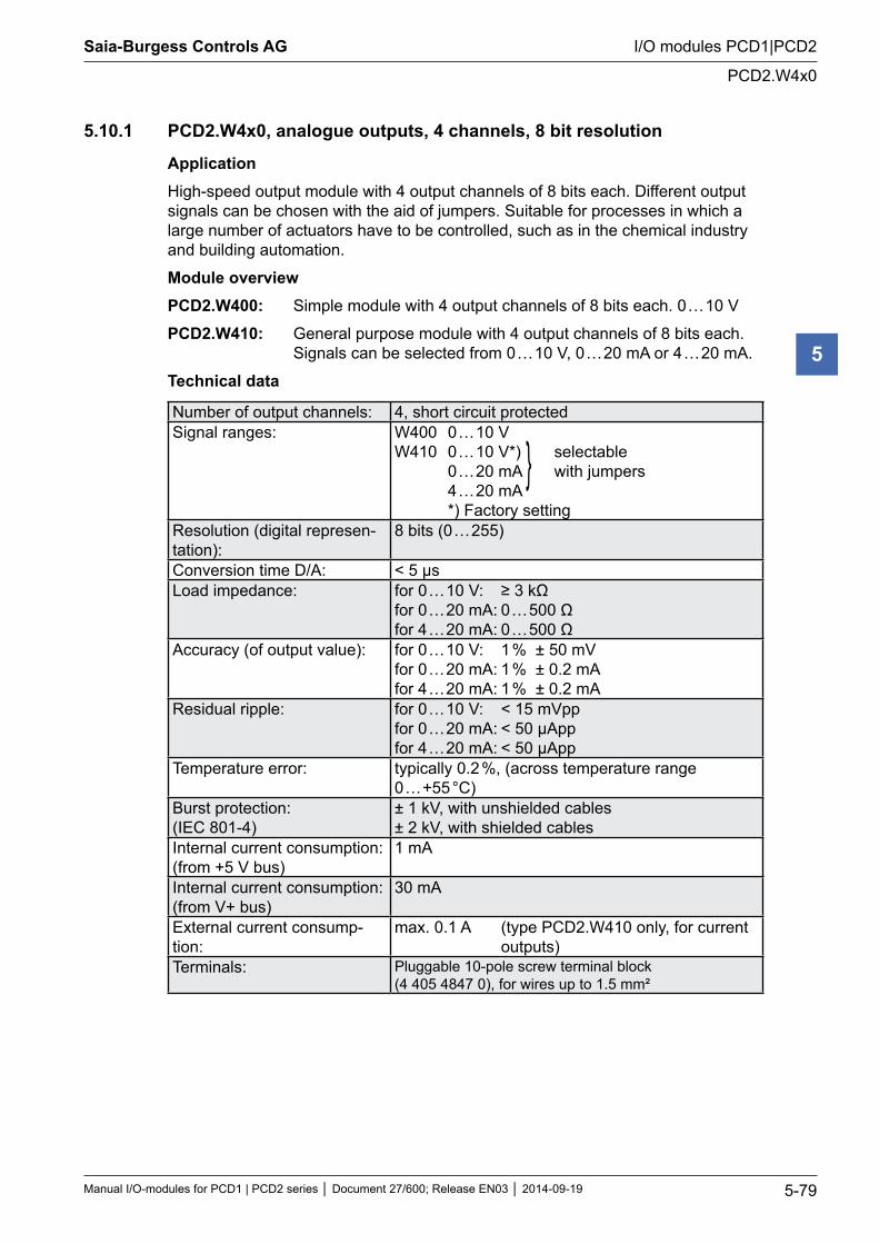
Saia-Burgess Controls AG
Manual I/O-modules for PCD1 | PCD2 series Document 27/600; Release EN03 2014-09-19 5-79
I/O modules PCD1|PCD2
PCD2.W4x0
5
5.10.1 PCD2.W4x0, analogue outputs, 4 channels, 8 bit resolution
ApplicationHigh-speed output module with 4 output channels of 8 bits each. Different output signals can be chosen with the aid of jumpers. Suitable for processes in which a large number of actuators have to be controlled, such as in the chemical industry and building automation.
Module overviewPCD2.W400: Simple module with 4 output channels of 8 bits each. 0 … 10 V
PCD2.W410: General purpose module with 4 output channels of 8 bits each. Signals can be selected from 0 … 10 V, 0 … 20 mA or 4 … 20 mA.
Technical data
Number of output channels: 4, short circuit protectedSignal ranges: W400 0 … 10 V
W410 0 … 10 V*) selectable 0 … 20 mA with jumpers 4 … 20 mA *) Factory setting
Resolution (digital represen-tation):
8 bits (0 … 255)
Conversion time D/A: < 5 µsLoad impedance: for 0 … 10 V: ≥ 3 kΩ
for 0 … 20 mA: 0 … 500 Ω for 4 … 20 mA: 0 … 500 Ω
Accuracy (of output value): for 0 … 10 V: 1 % ± 50 mV for 0 … 20 mA: 1 % ± 0.2 mA for 4 … 20 mA: 1 % ± 0.2 mA
Residual ripple: for 0 … 10 V: < 15 mVpp for 0 … 20 mA: < 50 µApp for 4 … 20 mA: < 50 µApp
Temperature error: typically 0.2 %, (across temperature range 0 … +55 °C)
Burst protection: (IEC 801-4)
± 1 kV, with unshielded cables ± 2 kV, with shielded cables
Internal current consumption: (from +5 V bus)
1 mA
Internal current consumption: (from V+ bus)
30 mA
External current consump-tion:
max. 0.1 A (type PCD2.W410 only, for current outputs)
Terminals: Pluggable 10-pole screw terminal block (4 405 4847 0), for wires up to 1.5 mm²
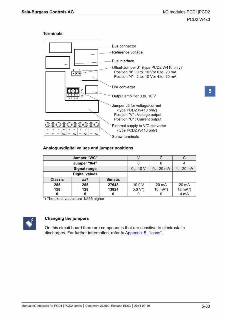
Saia-Burgess Controls AG
Manual I/O-modules for PCD1 | PCD2 series Document 27/600; Release EN03 2014-09-19 5-80
I/O modules PCD1|PCD2
PCD2.W4x0
5
Terminals
2 3 1 0
V
C
4 0
A0 A1 A2 A3 9 8 7 6 5 4 3 2 1 0
Bus connectorReference voltage
Bus interface
Offset-Jumper J1 (type PCD2.W410 only) Position "0" : 0.to. 10 Vor 0.to. 20 mA Position "4" : 2.to. 10 Vor 4.to. 20 mA
D/A converter
Output amplifier 0.to. 10 V
Jumper J2 for voltage/current (type PCD2.W410 only) Position "V" : Voltage output Position "C" : Current output
External supply to V/C converter (type PCD2.W410 only)Screw terminals
Analogue/digital values and jumper positions
Jumper “V/C” V C CJumper “0/4” 0 0 4Signal range 0 … 10 V 0 … 20 mA 4 … 20 mADigital values
Classic xx7 Simatic255128
0
255128
0
2764813824
0
10.0 V5.0 V*)
0
20 mA10 mA*)
0
20 mA12 mA*)
4 mA*) The exact values are 1/255 higher
Changing the jumpers
On this circuit board there are components that are sensitive to electrostatic discharges. For further information, refer to Appendix B, “Icons”.
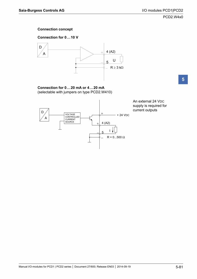
Saia-Burgess Controls AG
Manual I/O-modules for PCD1 | PCD2 series Document 27/600; Release EN03 2014-09-19 5-81
I/O modules PCD1|PCD2
PCD2.W4x0
5
Connection concept
Connection for 0 … 10 V
4 (A2)D
A
5 U
R 3 k
Connection for 0 … 20 mA or 4 … 20 mA (selectable with jumpers on type PCD2.W410)
4 (A2)
5 I
R = 0...500 Ω
D
AVOLTAGECONTROLLEDCURRENTSOURCE
+ 24 VDC
An external 24 VDC supply is required for current outputs
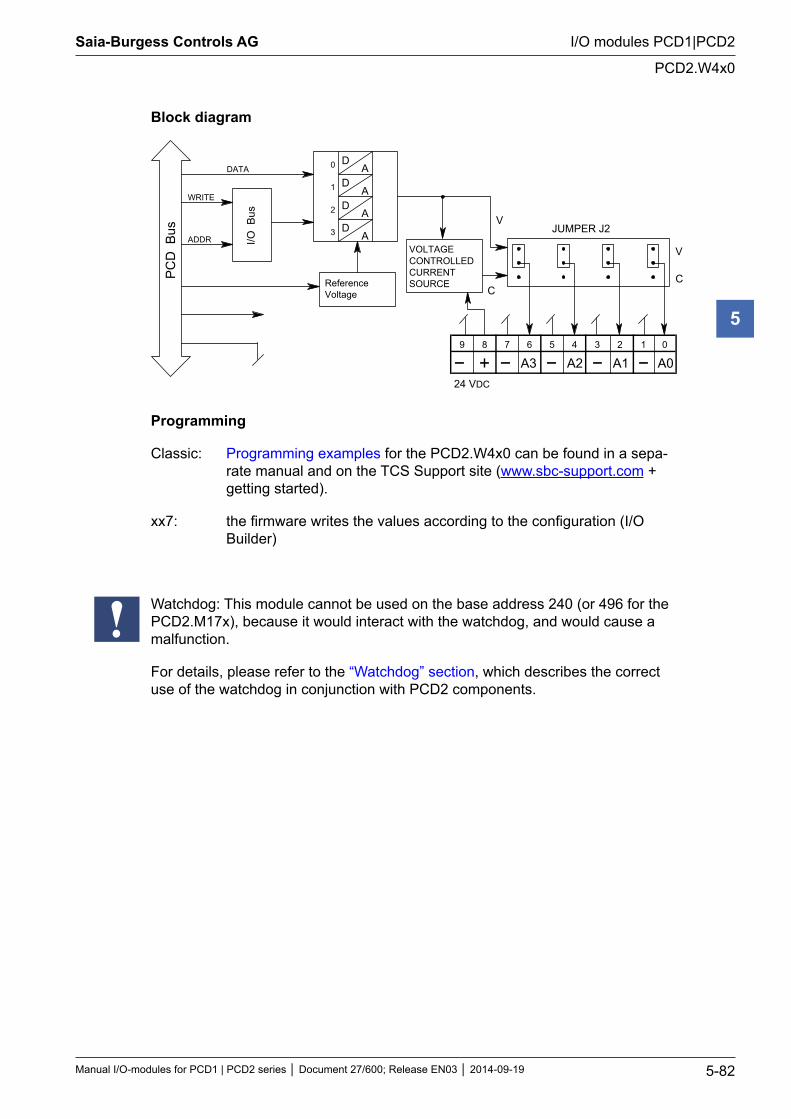
Saia-Burgess Controls AG
Manual I/O-modules for PCD1 | PCD2 series Document 27/600; Release EN03 2014-09-19 5-82
I/O modules PCD1|PCD2
PCD2.W4x0
5
Block diagram
D A
D A
D A
D A
2
3
V
C
9 8 7 6 5 4 3 2 1 0
A0 A1 A2 A3
V
C
0
1
I/O B
us
PC
D B
us
ReferenceVoltage
DATA
WRITE
ADDRJUMPER J2
24 VDC
VOLTAGECONTROLLEDCURRENTSOURCE
Programming
Classic: Programming examples for the PCD2.W4x0 can be found in a sepa-rate manual and on the TCS Support site (www.sbc-support.com + getting started).
xx7: the firmware writes the values according to the configuration (I/O Builder)
Watchdog: This module cannot be used on the base address 240 (or 496 for the PCD2.M17x), because it would interact with the watchdog, and would cause a malfunction.
For details, please refer to the “Watchdog” section, which describes the correct use of the watchdog in conjunction with PCD2 components.
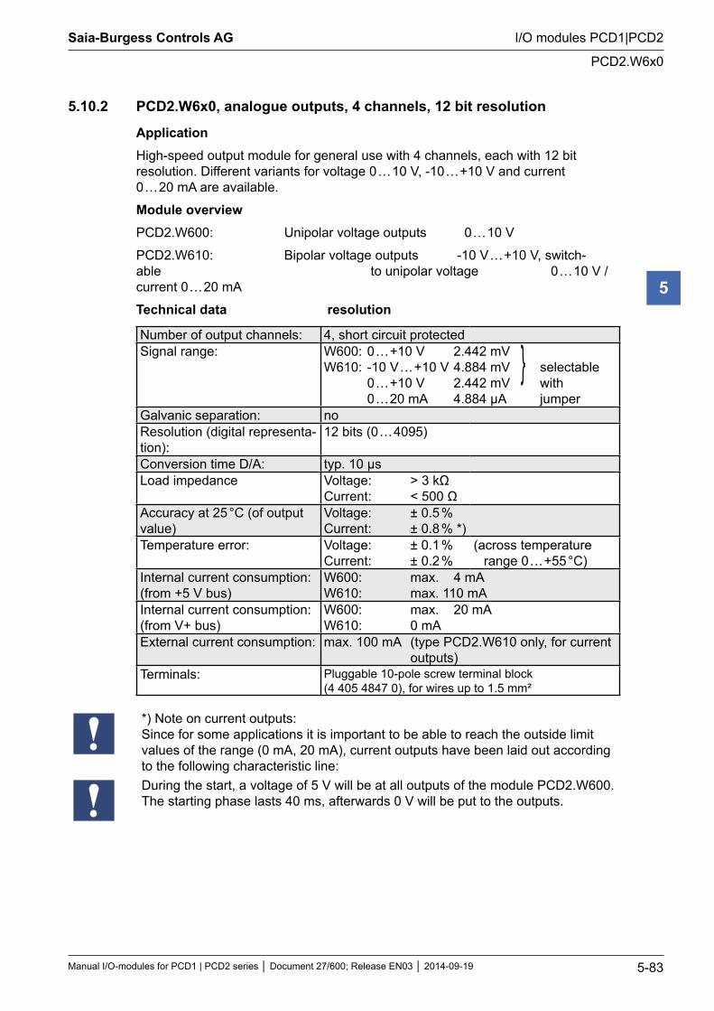
Saia-Burgess Controls AG
Manual I/O-modules for PCD1 | PCD2 series Document 27/600; Release EN03 2014-09-19 5-83
I/O modules PCD1|PCD2
PCD2.W6x0
5
5.10.2 PCD2.W6x0, analogue outputs, 4 channels, 12 bit resolution
ApplicationHigh-speed output module for general use with 4 channels, each with 12 bit resolution. Different variants for voltage 0 … 10 V, -10 … +10 V and current 0 … 20 mA are available.
Module overviewPCD2.W600: Unipolar voltage outputs 0 … 10 V
PCD2.W610: Bipolar voltage outputs -10 V … +10 V, switch-able to unipolar voltage 0 … 10 V / current 0 … 20 mA
Technical data resolution
Number of output channels: 4, short circuit protectedSignal range: W600: 0 … +10 V 2.442 mV
W610: -10 V … +10 V 4.884 mV selectable 0 … +10 V 2.442 mV with 0 … 20 mA 4.884 μA jumper
Galvanic separation: noResolution (digital representa-tion):
12 bits (0 … 4095)
Conversion time D/A: typ. 10 µsLoad impedance Voltage: > 3 kΩ
Current: < 500 ΩAccuracy at 25 °C (of output value)
Voltage: ± 0.5 % Current: ± 0.8 % *)
Temperature error: Voltage: ± 0.1 % Current: ± 0.2 %
(across temperature range 0 … +55 °C)
Internal current consumption: (from +5 V bus)
W600: max. 4 mA W610: max. 110 mA
Internal current consumption: (from V+ bus)
W600: max. 20 mA W610: 0 mA
External current consumption: max. 100 mA (type PCD2.W610 only, for current outputs)
Terminals: Pluggable 10-pole screw terminal block (4 405 4847 0), for wires up to 1.5 mm²
*) Note on current outputs: Since for some applications it is important to be able to reach the outside limit values of the range (0 mA, 20 mA), current outputs have been laid out according to the following characteristic line:During the start, a voltage of 5 V will be at all outputs of the module PCD2.W600. The starting phase lasts 40 ms, afterwards 0 V will be put to the outputs.
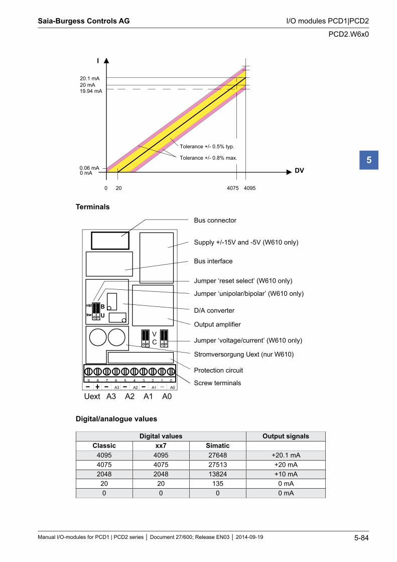
Saia-Burgess Controls AG
Manual I/O-modules for PCD1 | PCD2 series Document 27/600; Release EN03 2014-09-19 5-84
I/O modules PCD1|PCD2
PCD2.W6x0
5
20 mA20.1 mA
19.94 mA
0 mA0.06 mA
0 20 4075 4095
DV
I
Tolerance +/- 0.5% typ.
Tolerance +/- 0.8% max.
Terminals
9 8 7 6 5 4 3 2 1 0
A3 A2 A1 A0
Bus connector
Bus interface
Screw terminals
Uext A3 A2 A1 A0
BU
Supply +/-15V and -5V (W610 only)
Output amplifierVC
Jumper ‘unipolar/bipolar’ (W610 only)
D/A converter
Jumper ‘voltage/current’ (W610 only)
Protection circuit
Stromversorgung Uext (nur W610)
mid
low
Jumper ‘reset select’ (W610 only)
Digital/analogue values
Digital values Output signalsClassic xx7 Simatic
4095 4095 27648 +20.1 mA4075 4075 27513 +20 mA2048 2048 13824 +10 mA
20 20 135 0 mA0 0 0 0 mA
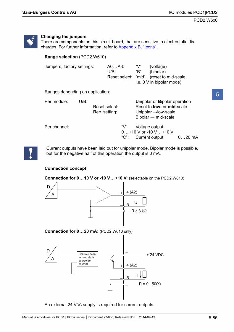
Saia-Burgess Controls AG
Manual I/O-modules for PCD1 | PCD2 series Document 27/600; Release EN03 2014-09-19 5-85
I/O modules PCD1|PCD2
PCD2.W6x0
5
Changing the jumpersThere are components on this circuit board, that are sensitive to electrostatic dis-charges. For further information, refer to Appendix B, “Icons”.
Range selection (PCD2.W610)
Jumpers, factory settings: A0 … A3: “V” (voltage) U/B: “B” (bipolar) Reset select: “mid“ (reset to mid-scale, i.e. 0 V in bipolar mode)
Ranges depending on application:
Per module: U/B: Unipolar or Bipolar operation Reset select: Reset to low- or mid-scale Rec. setting: Unipolar →low-scale Bipolar → mid-scale
Per channel: “V” Voltage output: 0 … +10 V or -10 V … +10 V “C”: Current output: 0 … 20 mA
Current outputs have been laid out for unipolar mode. Bipolar mode is possible, but for the negative half of this operation the output is 0 mA.
Connection concept
Connection for 0 … 10 V or -10 V … +10 V: (selectable on the PCD2.W610)
4 (A2)D
A
5 U
R ≥ 3 kΩ
Connection for 0 … 20 mA: (PCD2.W610 only)
4 (A2)
D
A
5 I
+ 24 VDC
R = 0.. 500 Ω
Contrôle de latension de lasource decourant
An external 24 VDC supply is required for current outputs.
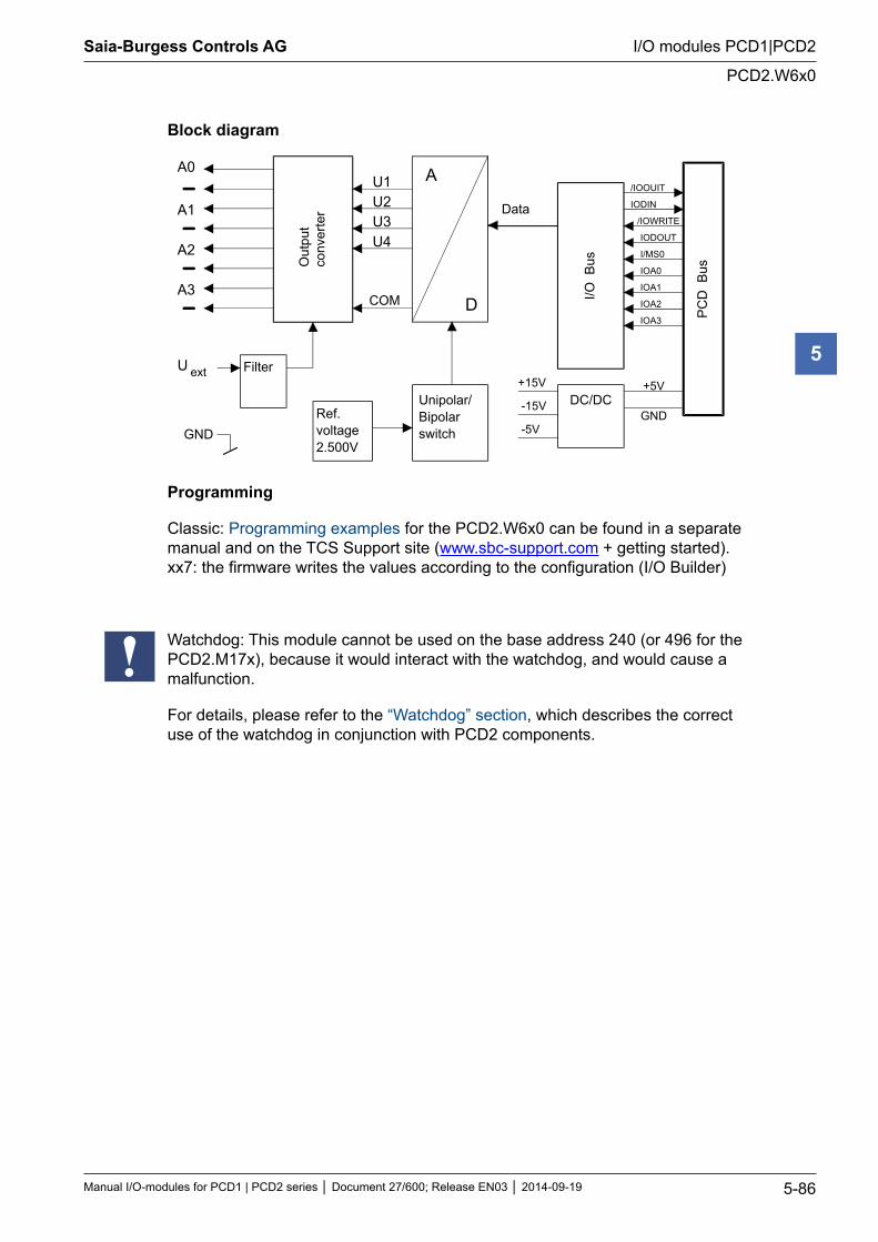
Saia-Burgess Controls AG
Manual I/O-modules for PCD1 | PCD2 series Document 27/600; Release EN03 2014-09-19 5-86
I/O modules PCD1|PCD2
PCD2.W6x0
5
Block diagram
A0
A1
A2
A3O
utpu
tco
nver
ter
A
D
Data
I/O B
us
PC
D B
us
+5V
GND
/IOOUIT
IODIN
/IOWRITE
IODOUT
I/MS0
IOA0
IOA1
IOA2
IOA3
+15V
-15V
-5V
Filter
Ref.voltage2.500V
Unipolar/Bipolarswitch
DC/DC
U ext
GND
U1U2U3U4
COM
Programming
Classic: Programming examples for the PCD2.W6x0 can be found in a separate manual and on the TCS Support site (www.sbc-support.com + getting started). xx7: the firmware writes the values according to the configuration (I/O Builder)
Watchdog: This module cannot be used on the base address 240 (or 496 for the PCD2.M17x), because it would interact with the watchdog, and would cause a malfunction.
For details, please refer to the “Watchdog” section, which describes the correct use of the watchdog in conjunction with PCD2 components.
Saia-Burgess Controls AG
Manual I/O-modules for PCD1 | PCD2 series Document 27/600; Release EN03 2014-09-19 5-87
I/O modules PCD1|PCD2
Analogue output modules with electrically isolation
5
5.11 Analogue output modules with electrically isolation
PCD2.W605 6 analogue inputs 10 bit resolution, 0 … 10 VPCD2.W615 4 analogue inputs 10 bit resolution, 0 … 20 mAPCD2.W625 6 analogue inputs 10 bit resolution, -10 V … +10 V
Galvanic separation of outputs to Saia PCD®, channels themselves not sepa-rated
I/O modules and I/O terminal blocks may only be plugged in and removed when the Saia PCD® and the external +24 V are disconnected from the power supply.
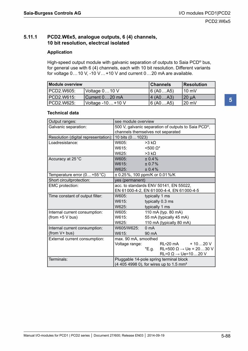
Saia-Burgess Controls AG
Manual I/O-modules for PCD1 | PCD2 series Document 27/600; Release EN03 2014-09-19 5-88
I/O modules PCD1|PCD2
PCD2.W6x5
5
5.11.1 PCD2.W6x5, analogue outputs, 6 (4) channels, 10 bit resolution, electrcal isolated
Application
High-speed output module with galvanic separation of outputs to Saia PCD® bus, for general use with 6 (4) channels, each with 10 bit resolution. Different variants for voltage 0 … 10 V, -10 V … +10 V and current 0 … 20 mA are available.
Module overview Channels ResolutionPCD2.W605: Voltage 0 … 10 V 6 (A0 … A5) 10 mVPCD2.W615: Current 0 … 20 mA 4 (A0 … A3) 20 μAPCD2.W625: Voltage -10 … +10 V 6 (A0 … A5) 20 mV
Technical data
Output ranges: see module overviewGalvanic separation: 500 V, galvanic separation of outputs to Saia PCD®,
channels themselves not separatedResolution (digital representation): 10 bits (0 … 1023)Loadresistance: W605: >3 kΩ
W615: <500 Ω* W625: >3 kΩ
Accuracy at 25 °C W605: ± 0.4 % W615: ± 0.7 % W625: ± 0.4 %
Temperature error (0 … +55 °C) ± 0.25 %, 100 ppm/K or 0.01 %/KShort circuitprotection: yes (permanent)EMC protection: acc. to standards ENV 50141, EN 55022,
EN 61 000-4-2, EN 61 000-4-4, EN 61 000-4-5Time constant of output filter: W605: typically 1 ms
W615: typically 0.3 ms W625: typically 1 ms
Internal current consumption: (from +5 V bus)
W605: 110 mA (typ. 80 mA) W615: 55 mA (typically 45 mA) W625: 110 mA (typically 80 mA)
Internal current consumption: (from V+ bus)
W605/W625: 0 mA W615: 90 mA
External current consumption: max. 90 mA, smoothed Voltage range: RL•20 mA + 10 … 20 V *E.g. RL=500 Ω → Ue = 20 … 30 V RL=0 Ω → Ue=10 … 20 V
Terminals: Pluggable 14-pole spring terminal block (4 405 4998 0), for wires up to 1.5 mm²
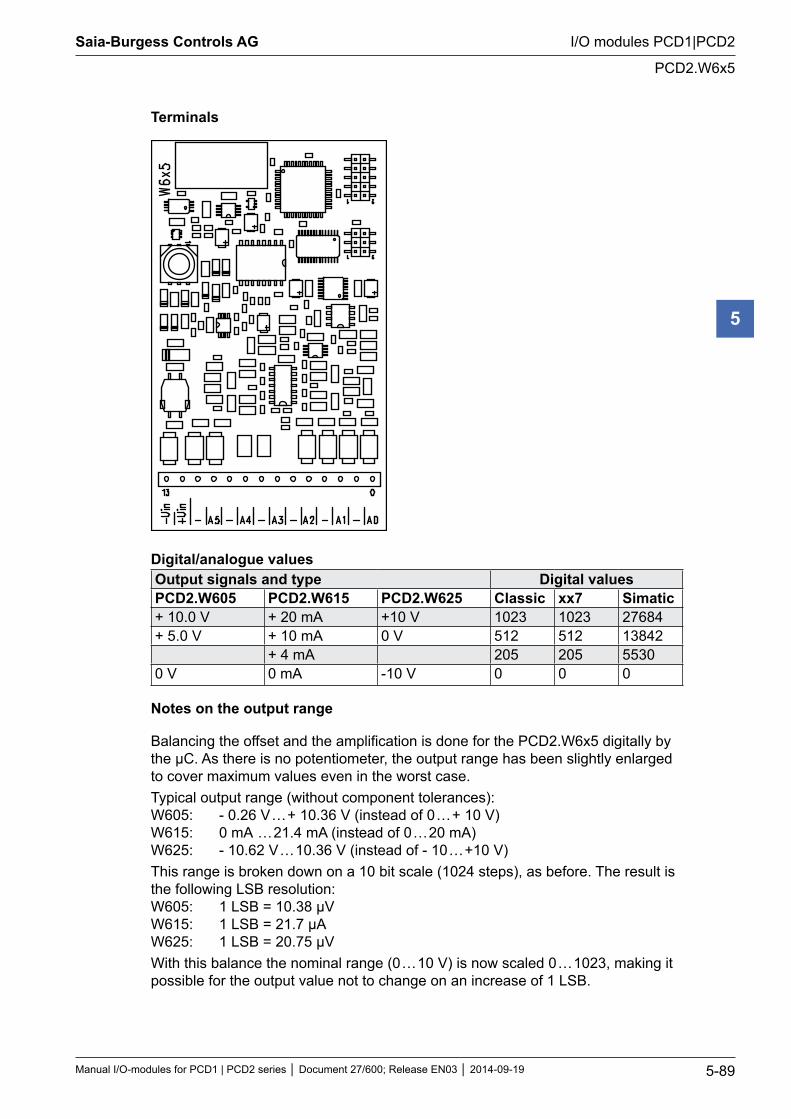
Saia-Burgess Controls AG
Manual I/O-modules for PCD1 | PCD2 series Document 27/600; Release EN03 2014-09-19 5-89
I/O modules PCD1|PCD2
PCD2.W6x5
5
Terminals
Digital/analogue valuesOutput signals and type Digital values PCD2.W605 PCD2.W615 PCD2.W625 Classic xx7 Simatic+ 10.0 V + 20 mA +10 V 1023 1023 27684+ 5.0 V + 10 mA 0 V 512 512 13842
+ 4 mA 205 205 55300 V 0 mA -10 V 0 0 0
Notes on the output range
Balancing the offset and the amplification is done for the PCD2.W6x5 digitally by the µC. As there is no potentiometer, the output range has been slightly enlarged to cover maximum values even in the worst case.Typical output range (without component tolerances): W605: - 0.26 V … + 10.36 V (instead of 0 … + 10 V) W615: 0 mA … 21.4 mA (instead of 0 … 20 mA) W625: - 10.62 V … 10.36 V (instead of - 10 … +10 V)This range is broken down on a 10 bit scale (1024 steps), as before. The result is the following LSB resolution: W605: 1 LSB = 10.38 µV W615: 1 LSB = 21.7 µA W625: 1 LSB = 20.75 µVWith this balance the nominal range (0 … 10 V) is now scaled 0 … 1023, making it possible for the output value not to change on an increase of 1 LSB.
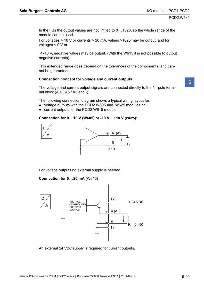
Saia-Burgess Controls AG
Manual I/O-modules for PCD1 | PCD2 series Document 27/600; Release EN03 2014-09-19 5-90
I/O modules PCD1|PCD2
PCD2.W6x5
5
In the FBs the output values are not limited to 0 … 1023, so the whole range of the module can be used.For voltages > 10 V or currents > 20 mA, values >1023 may be output, and for voltages < 0 V or
< -10 V, negative values may be output. (With the W615 it is not possible to output negative currents).
This extended range does depend on the tolerances of the components, and can-not be guaranteed.
Connection concept for voltage and current outputs
The voltage and current output signals are connected directly to the 14-pole termi-nal block (A0 … A5 / A3 and -).
The following connection diagram shows a typical wiring layout for: voltage outputs with the PCD2.W605 and .W625 modules or current outputs for the PCD2.W615 module
Connection for 0 … 10 V (W605) or -10 V … +10 V (W625):
D
A
5U
R ≥ 3 kΩ13
4 (A2)
For voltage outputs no external supply is needed.
Connection for 0 … 20 mA (W615)
4 (A2)
D
A
5I
VOLTAGECONTROLLEDCURRENTSOURCE
+ 24 VDC
R = 0...500 Ω 13
12
An external 24 VDC supply is required for current outputs.
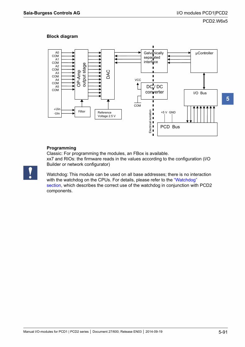
Saia-Burgess Controls AG
Manual I/O-modules for PCD1 | PCD2 series Document 27/600; Release EN03 2014-09-19 5-91
I/O modules PCD1|PCD2
PCD2.W6x5
5
Block diagram
OP
-Am
p ou
tput
sta
ge
A0 COM
A1 COM
A2 COM
A3 COM
A4 COM
A5 COM
DA
C
Reference Voltage 2.5 V
μController
PCD Bus
I/O Bus DC / DC converter
Galvanically separated interface
Ele
ctric
al is
olat
ion
VCC
COM
+5 V GND Filter +Uin -Uin
Programming Classic: For programming the modules, an FBox is available. xx7 and RIOs: the firmware reads in the values according to the configuration (I/O Builder or network configurator)
Watchdog: This module can be used on all base addresses; there is no interaction with the watchdog on the CPUs. For details, please refer to the “Watchdog” section, which describes the correct use of the watchdog in conjunction with PCD2 components.
Saia-Burgess Controls AG
Manual I/O-modules for PCD1 | PCD2 series Document 27/600; Release EN03 2014-09-19 5-92
I/O modules PCD1|PCD2
Analogue input and output modules
5
5.12 Analogue input and output modules
PCD2.W500 2 analogue inputs 12 bit + 2 analogue outputs 12 bit, 0 … 10 V, -10 V … +10 V *)
PCD2.W510 2 analogue inputs 12 bit + 2 analogue outputs 12 bit, 0 … +20 mA, -20 … +20 mA *)
*) jumper selectable
I/O modules and I/O terminal blocks may only be plugged in and removed when the Saia PCD® and the external +24 V are disconnected from the power supply.
Saia-Burgess Controls AG
Manual I/O-modules for PCD1 | PCD2 series Document 27/600; Release EN03 2014-09-19 5-93
I/O modules PCD1|PCD2
PCD2.W5x0
5
5.12.1 PCD2.W5x0, analogue inputs/outputs, 2 + 2 channels, 12 bit resolution
ApplicationCombined high speed analogue input/output module with 2 voltage inputs and 2 voltage outputs 0 … +10 V (unipolar) or -10 … +10 V (bipolar), jumper selectable, all with 12 bit resolution. The module is suitable for precise, high-speed applications.
Module overviewPCD2.W500: Combined high-speed analogue input/output module with 2 voltage inputs and 2 voltage outputs 0 … +10 V (unipolar) or - 10 … +10 V (bipolar), jumper selectable (standard module).
PCD2.W510: Module with 2 current inputs and 2 voltage outputs (special version)
Technical data
InputsNumber of input channels: 2Signal ranges W500: W510:
0 … +10 V jumper selectable -10 … +10 V together 0 … +20 mA jumper selectable -20 … +20 mA together
Galvanic separation: noMeasuring principle: differentialConversion timeA/D: < 30 µsResolution (digital representation): 12 bits (0 … 4095)Input resistance: 0 … +10 V :1 MΩ
0 … +20 mA: 100 ΩAccuracy (of measured value): unipolar: ± 2 LSB
bipolar: ± 10 LSBRepeating accuracy (under same conditions):
± 2 LSB
Common mode range: CMR ± 10 VCommon mode rejection: CMRR > 75 dBOvervoltage protection: ± 40 VCC (permanent)Time constant of input filter: 3 msOutputsNumber of output channels: 2, short circuit protectedSignal ranges: 0 … +10 V jumper selectable
-10 … +10 V individuallyGalvanic separation: noConversion time D/A: < 20 µsResolution (digital representation): 12 bits (0 … 4095)Load impedance: > 3 kΩAccuracy (of output value): 0.3 % ± 20 mV
Technical data common to the whole module
Burst protection: (IEC 801-4)
± 1 kV, with unshielded cables ± 2 kV, with shielded cables
Temperature error 0.3 % (across temperature range 0 … +55 °C)Internal current consumption:(from +5 V bus)
max. 200 mA
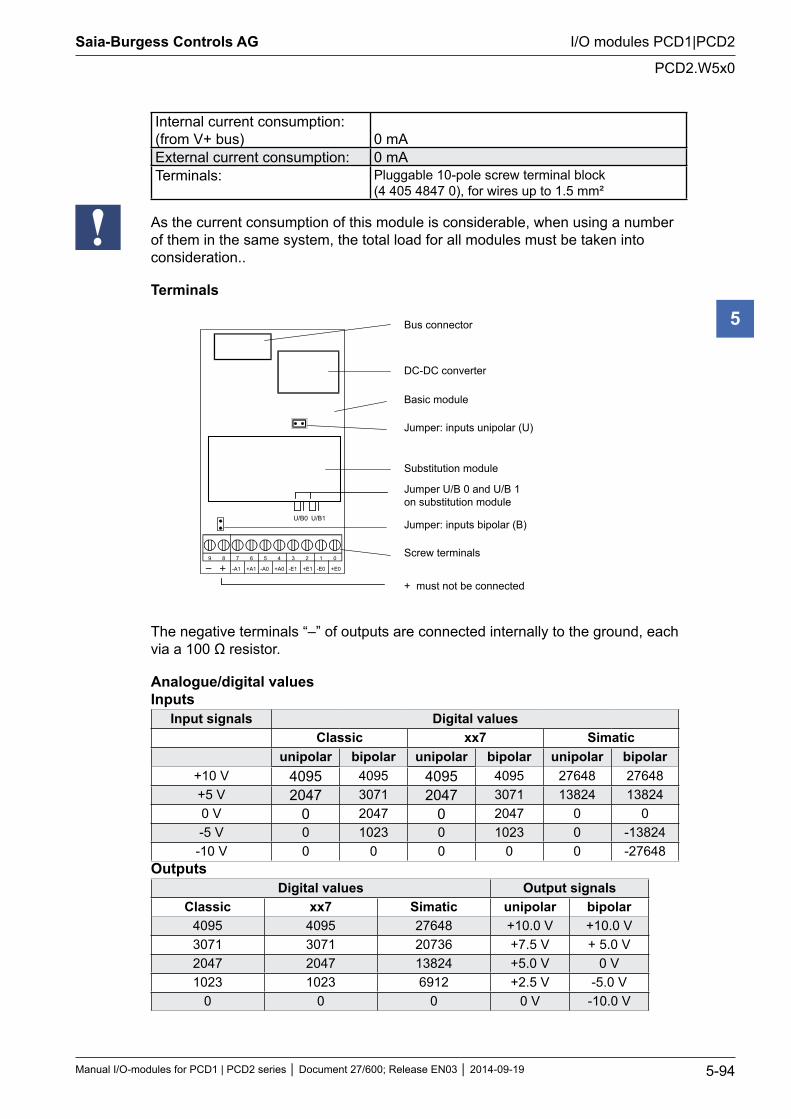
Saia-Burgess Controls AG
Manual I/O-modules for PCD1 | PCD2 series Document 27/600; Release EN03 2014-09-19 5-94
I/O modules PCD1|PCD2
PCD2.W5x0
5
Internal current consumption: (from V+ bus)
0 mA
External current consumption: 0 mATerminals: Pluggable 10-pole screw terminal block
(4 405 4847 0), for wires up to 1.5 mm²
As the current consumption of this module is considerable, when using a number of them in the same system, the total load for all modules must be taken into consideration..
Terminals
Bus connector
DC-DC converter
Basic module
Jumper: inputs unipolar (U)
Substitution module
Jumper U/B 0 and U/B 1on substitution module
Jumper: inputs bipolar (B)
Screw terminals
+ must not be connected
9 8 7 6 5 4 3 2 1 0
+A1-A1 +A0-A0 +E1-E1 +E0-E0
U/B0 U/B1
The negative terminals “–” of outputs are connected internally to the ground, each via a 100 Ω resistor.
Analogue/digital values Inputs
Input signals Digital values Classic xx7 Simatic
unipolar bipolar unipolar bipolar unipolar bipolar+10 V 4095 4095 4095 4095 27648 27648+5 V 2047 3071 2047 3071 13824 138240 V 0 2047 0 2047 0 0-5 V 0 1023 0 1023 0 -13824
-10 V 0 0 0 0 0 -27648Outputs
Digital values Output signalsClassic xx7 Simatic unipolar bipolar
4095 4095 27648 +10.0 V +10.0 V3071 3071 20736 +7.5 V + 5.0 V2047 2047 13824 +5.0 V 0 V1023 1023 6912 +2.5 V -5.0 V
0 0 0 0 V -10.0 V
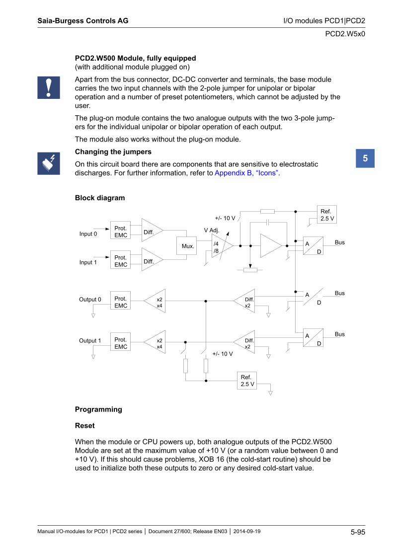
Saia-Burgess Controls AG
Manual I/O-modules for PCD1 | PCD2 series Document 27/600; Release EN03 2014-09-19 5-95
I/O modules PCD1|PCD2
PCD2.W5x0
5
PCD2.W500 Module, fully equipped (with additional module plugged on)
Apart from the bus connector, DC-DC converter and terminals, the base module carries the two input channels with the 2-pole jumper for unipolar or bipolar operation and a number of preset potentiometers, which cannot be adjusted by the user.
The plug-on module contains the two analogue outputs with the two 3-pole jump-ers for the individual unipolar or bipolar operation of each output.
The module also works without the plug-on module.
Changing the jumpersOn this circuit board there are components that are sensitive to electrostatic discharges. For further information, refer to Appendix B, “Icons”.
Block diagram
Prot.EMC Diff.
Mux.
Prot.EMC Diff.
Input 0
Input 1
/4/8
V Adj.
AD
Bus
Ref.2.5 V+/- 10 V
AD
BusDiff.x2
Prot.EMC
x2x4
AD
BusDiff.x2
Prot.EMC
x2x4
Output 0
Output 1
Ref.2.5 V
+/- 10 V
Programming
Reset
When the module or CPU powers up, both analogue outputs of the PCD2.W500 Module are set at the maximum value of +10 V (or a random value between 0 and +10 V). If this should cause problems, XOB 16 (the cold-start routine) should be used to initialize both these outputs to zero or any desired cold-start value.
Saia-Burgess Controls AG
Manual I/O-modules for PCD1 | PCD2 series Document 27/600; Release EN03 2014-09-19 5-96
I/O modules PCD1|PCD2
PCD2.W5x0
5
If the debugger is connected or the P100 handheld service device is plugged in, there is no cold-start when the CPU supply switches on. Both analogue outputs of the PCD2.W500 are then set to the maximum value of +10 V, despite the reset routine.
Classic: Programming examples for the PCD2.W500 can be found in a separate manual and on the TCS Support site (www.sbc-support.com + getting started). xx7: the firmware reads and writes the values according to the configuration (I/O Builder)
Watchdog: This module cannot be used on the base address 240 (or 496 for the PCD2.M17x), because it would interact with the watchdog, and would cause a malfunction. For details, please refer to the “Watchdog” section, which describes the correct use of the watchdog in conjunction with PCD2 components
.
Saia-Burgess Controls AG
Manual I/O-modules for PCD1 | PCD2 series Document 27/600; Release EN03 2014-09-19 5-97
I/O modules PCD1|PCD2
Combined analogue input/output modules with galvanic isolation
5
5.13 Combined analogue input/output modules with galvanic isola-tion
PCD2.W525 4 inputs, 14 bits, 0…10 V, 0(4)…20 mA, Pt 1000, Pt 500 or Ni 1000 (selectable by DIP switch)
and
2 outputs, 12 bits, 0…10 V or 0(4)…20 mA (selectable by software (FBox, FB)
Galvanic separation of outputs to Saia PCD®, channels themselves not sepa-rated
I/O modules and I/O terminal blocks may only be plugged in and removed when the Saia PCD® and the external +24 V are disconnected from the power supply.
Saia-Burgess Controls AG
Manual I/O-modules for PCD1 | PCD2 series Document 27/600; Release EN03 2014-09-19 5-98
I/O modules PCD1|PCD2
PCD2.W525 Combined analogue input/output module with galvanic isolation
5
5.13.1 PCD2.W525 Combined analogue input/output modules with galvanic isolation
General InformationPCD2.W525 is an analogue multipurpose module with four inputs and two outputs. Each input and each output can be individually configured as one of the stand-ard industrial interface type like 0 … 10 V, 0 … 20 mA and 4 … 20 mA. In addition, the inputs can be configured to support Pt/Ni1000 or Pt500 temperature sensors. Furthermore, the module offers high flexibility in selecting filter types and scaling ranges.
Inputs-14 Bit 4 Inputs. Every channel has four modes of operation (configurable by DIP- Switches):
Differential Voltage Inputs 0 … 10 V, resolution: 0.61 mV per LSB (14 Bit)
Differential Current Inputs-measured in differential mode 0 … 20 mA, resolution: 1.2 μA per LSB (14 Bit) 4 … 20 mA, resolution: 1.2 μA per LSB (13.7 Bit)
Temperature Pt1000, -50 … 400 °C, resolution: 0.1 °C Pt500, -50 … 400 °C, resolution: 0.2 °C Ni1000, -60 … 200 °C, resolution 0.1 °C
Resistance 0 … 2500 Ω, resolution 0.2 Ω
Each channel can be configured to have a software based 50 Hz / 60 Hz filter
Outputs-12 Bit 2 Outputs. Every channel has three modes of operation (configurable by soft- ware):
Voltage 0 … 10 V, resolution: 2.44 mV per LSB (12 Bit)
Current 0 … 20 mA, resolution: 4.88 μA per LSB (12 Bit) 4 … 20 mA, resolution 4.88 μA per LSB (11.7 Bit)
High impedanceMiscellaneous All I/O-Channels are galvanically isolated to the Saia PCD® and external power
supply. (But all channels are galvanically connected to each other.)
Every channel has two connection terminals.
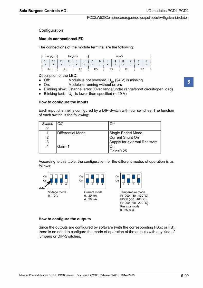
Saia-Burgess Controls AG
Manual I/O-modules for PCD1 | PCD2 series Document 27/600; Release EN03 2014-09-19 5-99
I/O modules PCD1|PCD2
PCD2.W525 Combined analogue input/output module with galvanic isolation
5
Configuration
Module connections/LED
The connections of the module terminal are the following:
Description of the LED: Off: Module is not powered. Uext (24 V) is missing. On: Module is running without errors Blinking slow: Channel error (Over range/under range/short circuit/open load) Blinking fast: Uext is lower than specified (< 19 V)
How to configure the inputs
Each input channel is configured by a DIP-Switch with four switches. The function of each switch is the following:
Switch nr.
Off On
1 2 3 4
Differential Mode Gain=1
Single Ended Mode Current Shunt On Supply for external Resistors On Gain=0.25
According to this table, the configuration for the different modes of operation is as follows:
Voltage mode0...10 V
Current mode0...20 mA4...20 mA
Temperature modePt1000 (-50...400 ˚C)Pt500 (-50...400 ˚C)Ni1000 (-60...200 ˚C)Resistor mode0...2500 Ω
1 2 3 4
OnOff
1 2 3 4
OnOff
1 2 3 4
OnOff
slider
How to configure the outputs
Since the outputs are configured by software (with the corresponding FBox or FB), there is no need to configure the mode of operation of the outputs with any kind of jumpers or DIP-Switches.
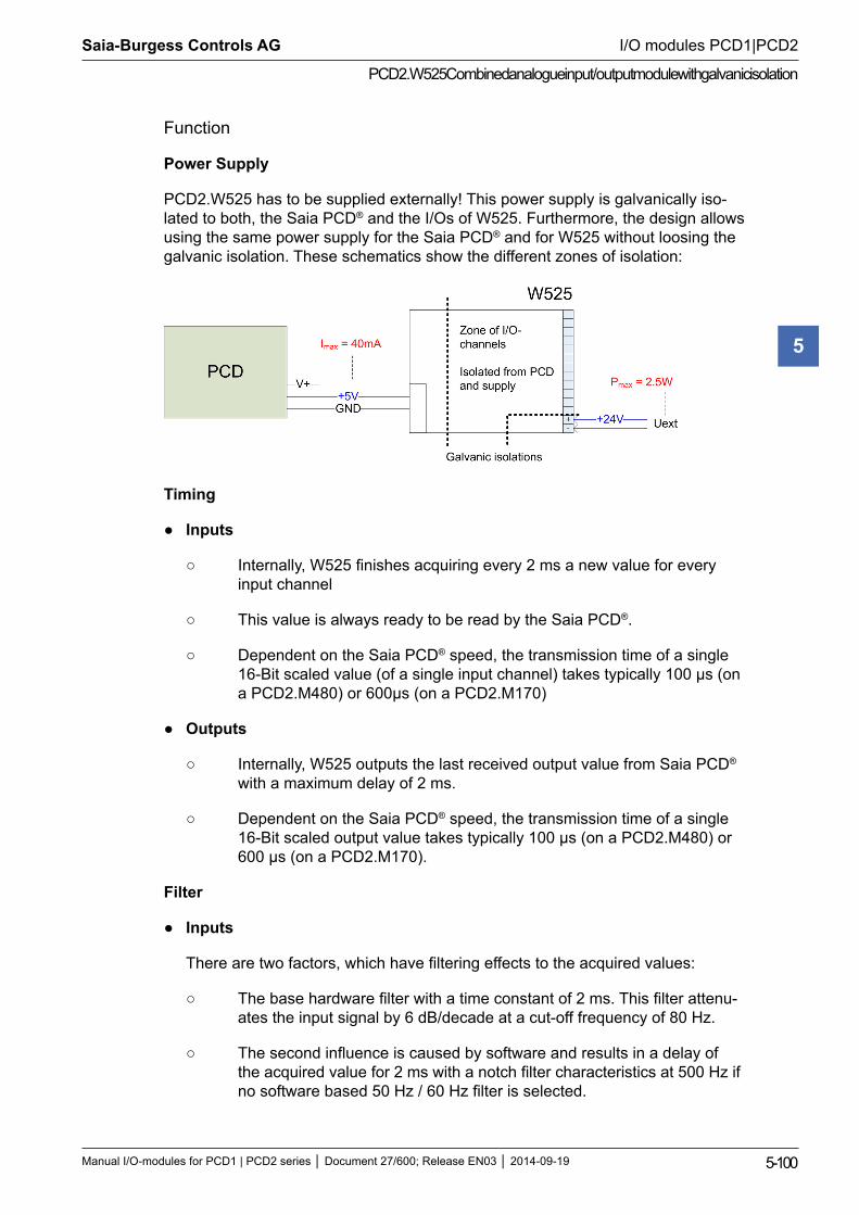
Saia-Burgess Controls AG
Manual I/O-modules for PCD1 | PCD2 series Document 27/600; Release EN03 2014-09-19 5-100
I/O modules PCD1|PCD2
PCD2.W525 Combined analogue input/output module with galvanic isolation
5
Function
Power Supply
PCD2.W525 has to be supplied externally! This power supply is galvanically iso-lated to both, the Saia PCD® and the I/Os of W525. Furthermore, the design allows using the same power supply for the Saia PCD® and for W525 without loosing the galvanic isolation. These schematics show the different zones of isolation:
Timing
Inputs
Internally, W525 finishes acquiring every 2 ms a new value for every input channel
This value is always ready to be read by the Saia PCD®.
Dependent on the Saia PCD® speed, the transmission time of a single 16-Bit scaled value (of a single input channel) takes typically 100 μs (on a PCD2.M480) or 600μs (on a PCD2.M170)
Outputs
Internally, W525 outputs the last received output value from Saia PCD® with a maximum delay of 2 ms.
Dependent on the Saia PCD® speed, the transmission time of a single 16-Bit scaled output value takes typically 100 μs (on a PCD2.M480) or 600 μs (on a PCD2.M170).
Filter
Inputs
There are two factors, which have filtering effects to the acquired values:
The base hardware filter with a time constant of 2 ms. This filter attenu- ates the input signal by 6 dB/decade at a cut-off frequency of 80 Hz.
The second influence is caused by software and results in a delay of the acquired value for 2 ms with a notch filter characteristics at 500 Hz if no software based 50 Hz / 60 Hz filter is selected.
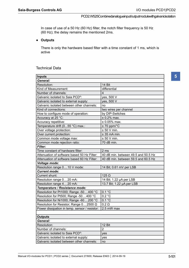
Saia-Burgess Controls AG
Manual I/O-modules for PCD1 | PCD2 series Document 27/600; Release EN03 2014-09-19 5-101
I/O modules PCD1|PCD2
PCD2.W525 Combined analogue input/output module with galvanic isolation
5
In case of use of a 50 Hz (60 Hz) filter, the notch filter frequency is 50 Hz (60 Hz); the delay remains the mentioned 2ms.
Outputs
There is only the hardware based filter with a time constant of 1 ms, which is active
Technical Data
InputsGeneral:Resolution: 14 BitKind of Measurement: differential Number of channels: 4Galvanic isolated to Saia PCD®: yes, 500 VGalvanic isolated to external supply: yes, 500 VGalvanic isolated between other channels: noKind of connections: two wires per channelHow to configure mode of operation: by DIP-SwitchesAccuracy at 25 °C: ± 0.2% max.Accuracy repetitive: ± 0.05% max.Temperature drift (0...55 °C) max.: ± 70 ppm/°COver voltage protection: ± 50 V min.Over current protection: ± 35 mA min.Common mode voltage max: ± 50 V min.Common mode rejection ratio: 70 dB min.Filter:Time constant of hardware filter: 2 msAttenuation of software based 50 Hz Filter: 40 dB min. between 49.5 and 50.5 HzAttenuation of software based 60 Hz Filter: 40 dB min. between 59.5 and 60.5 HzVoltage mode:Resolution range 0 … 10 V mode: 14 Bit; 0.61 mV per LSBCurrent mode:Current shunt: 125 ΩResolution range 0 … 20 mA: 14 Bit; 1.22 µA per LSBResolution range 4 … 20 mA: 13.7 Bit; 1.22 µA per LSBTemperature / Resistance mode:Resolution for Pt1000; Range -50 … 400 °C 0.1 °CResolution for Pt500; Range -50 … 400 °C 0.2 °CResolution for Ni1000; Range -60 … 200 °C 0.1 °CResolution for Resistor; Range 0 … 2500 Ω 0.2 ΩPower dissipation in temp. sensor / resistor: 2.5 mW max
OutputsGeneral:Resolution: 12 BitNumber of channels: 2Galvanic isolated to Saia PCD®: yesGalvanic isolated to external supply: yesGalvanic isolated between other channels: no
Saia-Burgess Controls AG
Manual I/O-modules for PCD1 | PCD2 series Document 27/600; Release EN03 2014-09-19 5-102
I/O modules PCD1|PCD2
PCD2.W525 Combined analogue input/output module with galvanic isolation
5
Kind of connections: two wires per channelHow to configure mode of operation: by software (FBOX, FB)Accuracy at 25 °C: ± 0.5% max.Accuracy repetitive: ± 0.1% max.Temperature drift (0...55 °C) max.: ± 70 ppm/°C.Over current protection: short circuit protectedTime constant of filter: 1 msVoltage mode:Max. load to guarantee specified accuracy: > 700 ΩResolution range 0 … 10 V: 12 Bit; 2.44 mV per LSBCurrent mode:Working resistance: < 600 ΩResolution range 0 … 20 mA: 12 Bit; 4.88 µA per LSBResolution range 4 … 20 mA: 11.7 Bit; 4.88 µA per LSB
General DataPower consumption at I/O-Bus +5V: max. 40 mAPower consumption at I/O-Bus V+: unloadedTemperature range: 0...55 °C
External power supply(It is possible and allowed to use the same power supply as the Saia PCD® itself is sup-plied with – without losing the galvanic isolation of the I/Os!)Operation voltage: 24 V ±4 V smoothedPower consumption: max. 2.5 W (depends on output load)
Terminal: PCD2 Pluggable 14-pole screw terminal (PCD2.W525; O no. 4 405 5002 0, will be delivered with the module), both for wires up to 1,5 mm²
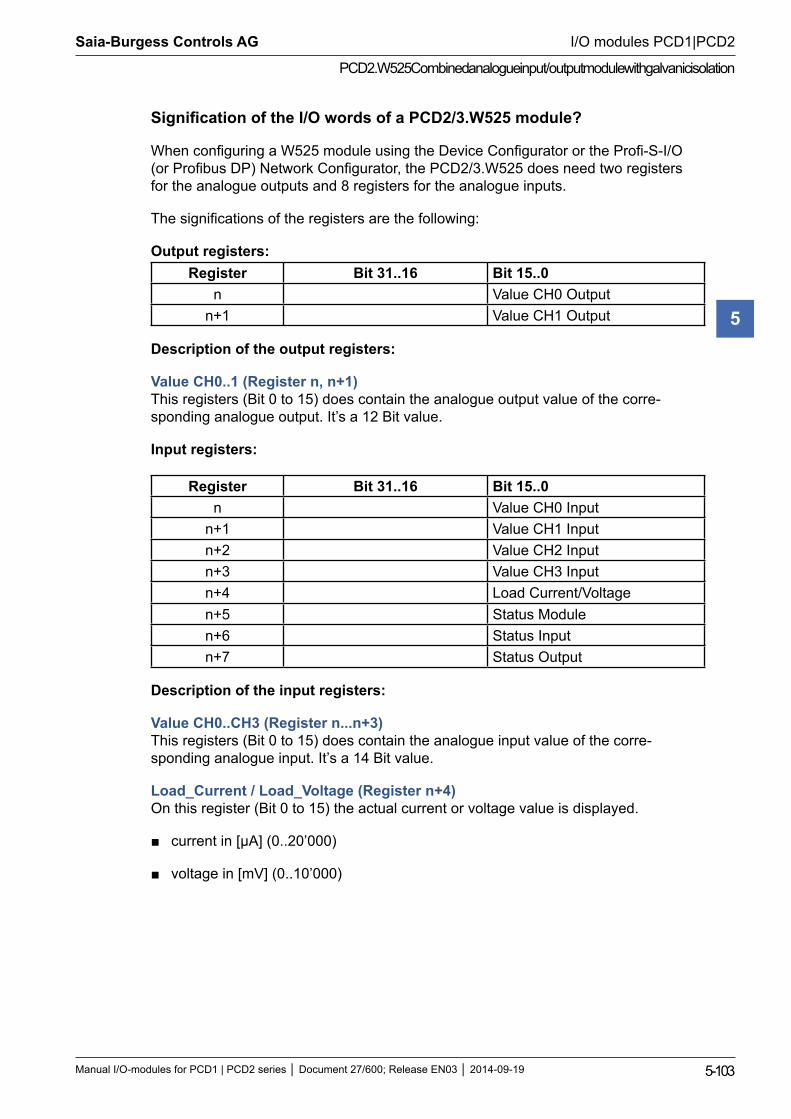
Saia-Burgess Controls AG
Manual I/O-modules for PCD1 | PCD2 series Document 27/600; Release EN03 2014-09-19 5-103
I/O modules PCD1|PCD2
PCD2.W525 Combined analogue input/output module with galvanic isolation
5
Signification of the I/O words of a PCD2/3.W525 module?
When configuring a W525 module using the Device Configurator or the Profi-S-I/O (or Profibus DP) Network Configurator, the PCD2/3.W525 does need two registers for the analogue outputs and 8 registers for the analogue inputs.
The significations of the registers are the following:
Output registers: Register Bit 31..16 Bit 15..0
n Value CH0 Outputn+1 Value CH1 Output
Description of the output registers:
Value CH0..1 (Register n, n+1) This registers (Bit 0 to 15) does contain the analogue output value of the corre-sponding analogue output. It’s a 12 Bit value.
Input registers:
Register Bit 31..16 Bit 15..0n Value CH0 Input
n+1 Value CH1 Inputn+2 Value CH2 Inputn+3 Value CH3 Inputn+4 Load Current/Voltagen+5 Status Modulen+6 Status Inputn+7 Status Output
Description of the input registers:
Value CH0..CH3 (Register n...n+3) This registers (Bit 0 to 15) does contain the analogue input value of the corre-sponding analogue input. It’s a 14 Bit value.
Load_Current / Load_Voltage (Register n+4) On this register (Bit 0 to 15) the actual current or voltage value is displayed.
current in [μA] (0..20’000)
voltage in [mV] (0..10’000)
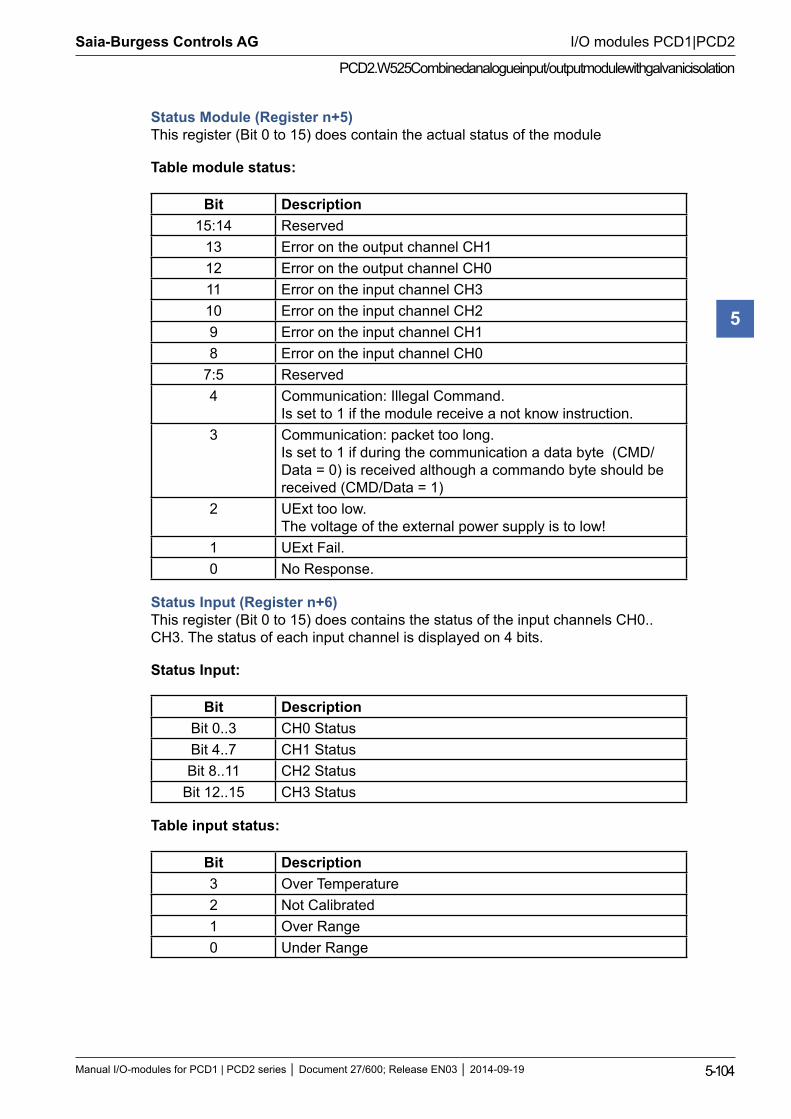
Saia-Burgess Controls AG
Manual I/O-modules for PCD1 | PCD2 series Document 27/600; Release EN03 2014-09-19 5-104
I/O modules PCD1|PCD2
PCD2.W525 Combined analogue input/output module with galvanic isolation
5
Status Module (Register n+5) This register (Bit 0 to 15) does contain the actual status of the module
Table module status:
Bit Description15:14 Reserved
13 Error on the output channel CH112 Error on the output channel CH011 Error on the input channel CH310 Error on the input channel CH29 Error on the input channel CH18 Error on the input channel CH0
7:5 Reserved4 Communication: Illegal Command.
Is set to 1 if the module receive a not know instruction.3 Communication: packet too long.
Is set to 1 if during the communication a data byte (CMD/Data = 0) is received although a commando byte should be received (CMD/Data = 1)
2 UExt too low. The voltage of the external power supply is to low!
1 UExt Fail.0 No Response.
Status Input (Register n+6) This register (Bit 0 to 15) does contains the status of the input channels CH0..CH3. The status of each input channel is displayed on 4 bits.
Status Input:
Bit DescriptionBit 0..3 CH0 StatusBit 4..7 CH1 StatusBit 8..11 CH2 Status
Bit 12..15 CH3 Status
Table input status:
Bit Description3 Over Temperature2 Not Calibrated1 Over Range0 Under Range
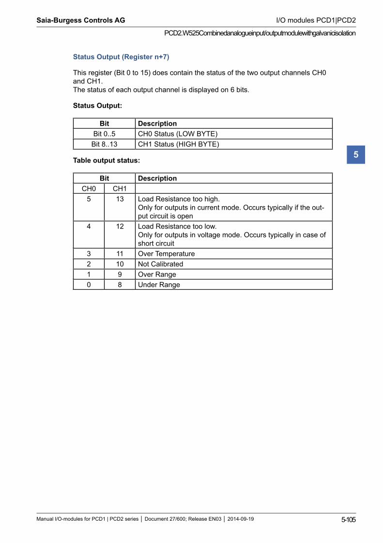
Saia-Burgess Controls AG
Manual I/O-modules for PCD1 | PCD2 series Document 27/600; Release EN03 2014-09-19 5-105
I/O modules PCD1|PCD2
PCD2.W525 Combined analogue input/output module with galvanic isolation
5
Status Output (Register n+7)
This register (Bit 0 to 15) does contain the status of the two output channels CH0 and CH1. The status of each output channel is displayed on 6 bits.
Status Output:
Bit DescriptionBit 0..5 CH0 Status (LOW BYTE)
Bit 8..13 CH1 Status (HIGH BYTE)
Table output status:
Bit DescriptionCH0 CH1
5 13 Load Resistance too high. Only for outputs in current mode. Occurs typically if the out-put circuit is open
4 12 Load Resistance too low. Only for outputs in voltage mode. Occurs typically in case of short circuit
3 11 Over Temperature2 10 Not Calibrated1 9 Over Range0 8 Under Range
Saia-Burgess Controls AG
Manual I/O-modules for PCD1 | PCD2 series Document 27/600; Release EN03 2014-09-19 5-106
I/O modules PCD1|PCD2
Analogue weighing modules
5
5.14 Analogue weighing modules
PCD2.W720 2-channel weighing module for 4/6-wire elements
I/O modules and I/O terminal blocks may only be plugged in and removed when the Saia PCD® and the external +24 V are disconnected from the power supply.
The module PCD2.W720 is described in the manual 26/833.
Saia-Burgess Controls AG
Manual I/O-modules for PCD1 | PCD2 series Document 27/600; Release EN03 2014-09-19 5-107
I/O modules PCD1|PCD2
Analogue I/O modules
5
5.15 Analogue thermocouple modules
PCD2.W745 4-channel thermocouple modules for J, K … thermoelemets
Supported temperature sensors are:
Thermocouples – TC type J, K
Resistive temperature detectors – RTD’s type Pt 100, Pt 1000, Ni 100, Ni 1000
I/O modules and I/O terminal blocks may only be plugged in and removed when the Saia PCD® and the external +24 V are disconnected from the power supply.
The module PCD2.W745 is described in the manual 26/796.
Saia-Burgess Controls AG
Manual I/O-modules for PCD1 | PCD2 series Document 27/600; Release EN03 2014-09-19 5-108
I/O modules PCD1|PCD2
Fast counting modules
5
5.16 Fast counting modules
PCD2.H100 Counting module up to 20 kHz
PCD2.H110 General purpose counting and measuring module up to 100 kHz
I/O modules and I/O terminal blocks may only be plugged in and removed when the Saia PCD® and the external +24 V are disconnected from the power supply.
Saia-Burgess Controls AG
Manual I/O-modules for PCD1 | PCD2 series Document 27/600; Release EN03 2014-09-19 5-109
I/O modules PCD1|PCD2
PCD2.H100
5
5.16.1 PCD2.H100, counting module up to 20 kHz
ApplicationSimple counting module, comprising two inputs “A” and “B” plus one direct control output marked “CCO”; allows counting of the number of revolutions or the calculation of distances (pulses) and the measurement by counting of pulses within a logical AND gate (second input). Typical areas of application: Counting revolutions or distances (impulses) Presetting a count value and switching off output CCO when Counter = 0 Measurement by counting: measuring signals counted only when particular conditions are met, e.g. photoelectric barrier covered Counting with recognition of count direction for incremental shaft encoders providing simple motion controlTechnical dataNumber of systems: 1Counting range: 0 … 65,535 (16 bit) (can be extended with CPU counters)Counting frequency: max. 20 kHz (at pulse/pause ratio 50 %)Data protection: All data in this module are volatile
(non-volatile Saia PCD® registers are available).Digital inputs“IN-A” and “IN-B” signal voltages: nominal voltage: 24 VDC
“low” range: -30 … +5 V “high” range: +15 … 30 V for source operation
Input current: typically 7.5 mAInput filer: 25 kHzProcess outputCounter controlled output CCO: counter output (switches when count is 0 or 65,535)Current range: 5 … 500 mA (max. current leakage 1 mA)
(min. load resistance 48 Ω in voltage range 5 … 24 V).
Voltage range: 5 … 32 V smoothed, residual ripple max. 10 %Circuit type: Electrically coupled, not short circuit protected,
positive switchingVoltage drop: typically 2V at 500 mAOutput delay: < 10 µs, (longer for inductive load due to
protective diode).Power supplyExternal supply 5 … 32 VDC, (for supply of CCO output only)Internal current consumption: (from +5 V bus)
max. 90 mA
Internal current consumption: (from V+ bus)
0 mA
External current consumption: CCO output load currentOperational conditionsAmbient temperature operation: 0 … +55 °C without forced ventilation,
storage: -20 … +85 °CNoise immunity: EC mark according to EN 61 000-6-3 and EN 61 000-6-2Programming: Based on Saia PCD® user program and pre-programmed
function blocks (FB). Count modes: Selectable with jumperTerminals: Pluggable 10-pole screw terminal block
(4 405 4847 0), for wires up to 1.5 mm²
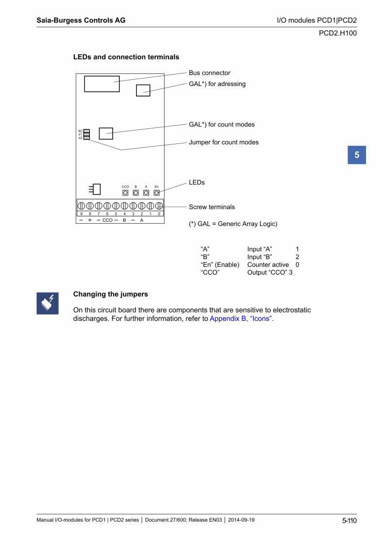
Saia-Burgess Controls AG
Manual I/O-modules for PCD1 | PCD2 series Document 27/600; Release EN03 2014-09-19 5-110
I/O modules PCD1|PCD2
PCD2.H100
5
LEDs and connection terminals
9 8 7 6 5 4 3 2 1 0
A B CCO
CCO B A En
SC x1 x2
Bus connector
GAL*) for adressing
GAL*) for count modes
Jumper for count modes
LEDs
Screw terminals
(*) GAL = Generic Array Logic)
Changing the jumpers
On this circuit board there are components that are sensitive to electrostatic discharges. For further information, refer to Appendix B, “Icons”.
“A” Input “A” 1 “B” Input “B” 2 “En” (Enable) Counter active 0 “CCO” Output “CCO” 3
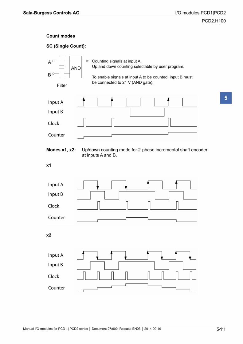
Saia-Burgess Controls AG
Manual I/O-modules for PCD1 | PCD2 series Document 27/600; Release EN03 2014-09-19 5-111
I/O modules PCD1|PCD2
PCD2.H100
5
Count modes
SC (Single Count):
ANDA
B
Filter
Counting signals at input A. Up and down counting selectable by user program.
To enable signals at input A to be counted, input B must be connected to 24 V (AND gate).
Input A
Input B
Clock
Counter
Modes x1, x2: Up/down counting mode for 2-phase incremental shaft encoder at inputs A and B.
x1
Input A
Input B
Clock
Counter
x2
Input A
Input B
Clock
Counter
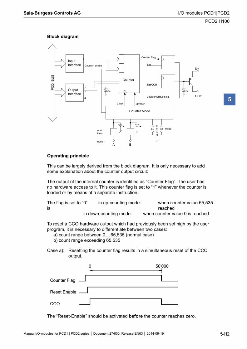
Saia-Burgess Controls AG
Manual I/O-modules for PCD1 | PCD2 series Document 27/600; Release EN03 2014-09-19 5-112
I/O modules PCD1|PCD2
PCD2.H100
5
Block diagram
A B
SC x1 x2
CCO
U+
Input Interface
Output Interface
Counter Flag
Counter enable
Counter Mode
up/down Clock
Set CCO
PC
D B
US
Input filters
Inputs
Mode
Counter Status Flag
Counter
Set
Set CCO
Operating principle
This can be largely derived from the block diagram. It is only necessary to add some explanation about the counter output circuit:
The output of the internal counter is identified as “Counter Flag”. The user has no hardware access to it. This counter flag is set to “1” whenever the counter is loaded or by means of a separate instruction.
The flag is set to “0” in up-counting mode: when counter value 65,535 is reached in down-counting mode: when counter value 0 is reached
To reset a CCO hardware output which had previously been set high by the user program, it is necessary to differentiate between two cases: a) count range between 0 … 65,535 (normal case) b) count range exceeding 65,535
Case a): Resetting the counter flag results in a simultaneous reset of the CCO output.
0 50'000
Counter Flag
Reset Enable
CCO
The “Reset-Enable” should be activated before the counter reaches zero.
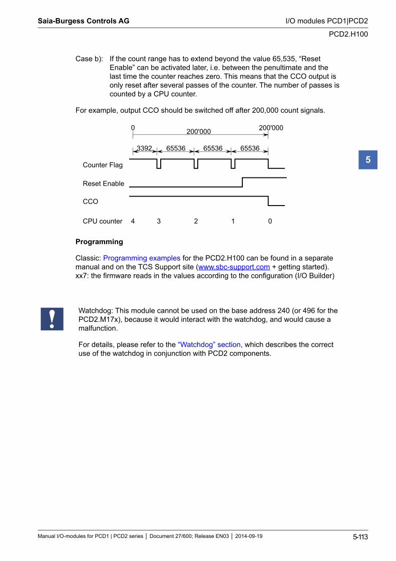
Saia-Burgess Controls AG
Manual I/O-modules for PCD1 | PCD2 series Document 27/600; Release EN03 2014-09-19 5-113
I/O modules PCD1|PCD2
PCD2.H100
5
Case b): If the count range has to extend beyond the value 65,535, “Reset Enable” can be activated later, i.e. between the penultimate and the last time the counter reaches zero. This means that the CCO output is only reset after several passes of the counter. The number of passes is counted by a CPU counter.
For example, output CCO should be switched off after 200,000 count signals.
0 200'000
3392 65536 65536 65536
200'000
3 2 1 0 4
Counter Flag
Reset Enable
CCO
CPU counter
Programming
Classic: Programming examples for the PCD2.H100 can be found in a separate manual and on the TCS Support site (www.sbc-support.com + getting started). xx7: the firmware reads in the values according to the configuration (I/O Builder)
Watchdog: This module cannot be used on the base address 240 (or 496 for the PCD2.M17x), because it would interact with the watchdog, and would cause a malfunction.
For details, please refer to the “Watchdog” section, which describes the correct use of the watchdog in conjunction with PCD2 components.
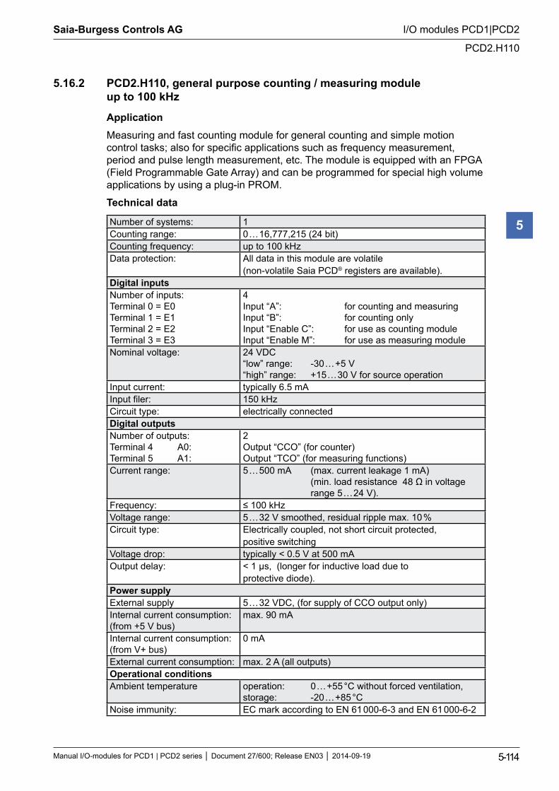
Saia-Burgess Controls AG
Manual I/O-modules for PCD1 | PCD2 series Document 27/600; Release EN03 2014-09-19 5-114
I/O modules PCD1|PCD2
PCD2.H110
5
5.16.2 PCD2.H110, general purpose counting / measuring module up to 100 kHz
ApplicationMeasuring and fast counting module for general counting and simple motion control tasks; also for specific applications such as frequency measurement, period and pulse length measurement, etc. The module is equipped with an FPGA (Field Programmable Gate Array) and can be programmed for special high volume applications by using a plug-in PROM.
Technical data
Number of systems: 1Counting range: 0 … 16,777,215 (24 bit)Counting frequency: up to 100 kHzData protection: All data in this module are volatile
(non-volatile Saia PCD® registers are available).Digital inputsNumber of inputs: Terminal 0 = E0 Terminal 1 = E1 Terminal 2 = E2 Terminal 3 = E3
4 Input “A”: for counting and measuring Input “B”: for counting only Input “Enable C”: for use as counting module Input “Enable M”: for use as measuring module
Nominal voltage: 24 VDC “low” range: -30 … +5 V “high” range: +15 … 30 V for source operation
Input current: typically 6.5 mAInput filer: 150 kHzCircuit type: electrically connectedDigital outputsNumber of outputs: Terminal 4 A0: Terminal 5 A1:
2 Output “CCO” (for counter) Output “TCO” (for measuring functions)
Current range: 5 … 500 mA (max. current leakage 1 mA) (min. load resistance 48 Ω in voltage range 5 … 24 V).
Frequency: ≤ 100 kHzVoltage range: 5 … 32 V smoothed, residual ripple max. 10 %Circuit type: Electrically coupled, not short circuit protected,
positive switchingVoltage drop: typically < 0.5 V at 500 mAOutput delay: < 1 µs, (longer for inductive load due to
protective diode).Power supplyExternal supply 5 … 32 VDC, (for supply of CCO output only)Internal current consumption: (from +5 V bus)
max. 90 mA
Internal current consumption: (from V+ bus)
0 mA
External current consumption: max. 2 A (all outputs)Operational conditionsAmbient temperature operation: 0 … +55 °C without forced ventilation,
storage: -20 … +85 °CNoise immunity: EC mark according to EN 61 000-6-3 and EN 61 000-6-2
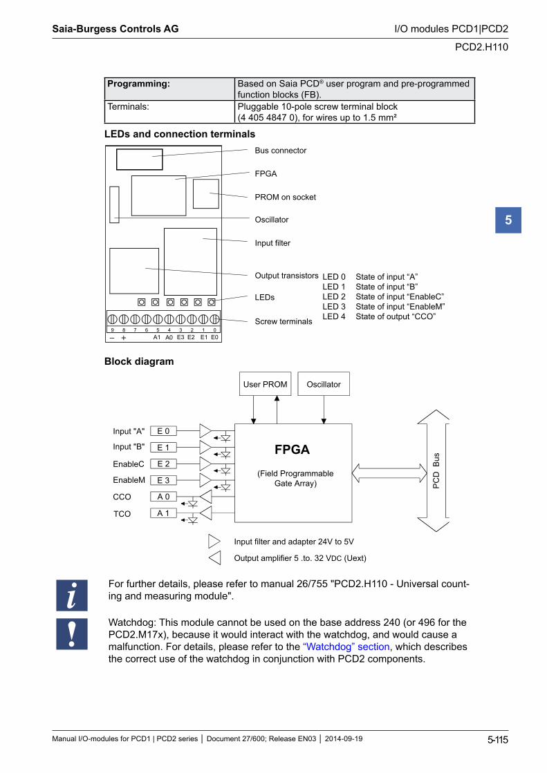
Saia-Burgess Controls AG
Manual I/O-modules for PCD1 | PCD2 series Document 27/600; Release EN03 2014-09-19 5-115
I/O modules PCD1|PCD2
PCD2.H110
5
Programming: Based on Saia PCD® user program and pre-programmed function blocks (FB).
Terminals: Pluggable 10-pole screw terminal block (4 405 4847 0), for wires up to 1.5 mm²
LEDs and connection terminals
9 8 7 6 5 4 3 2 1 0 A0 A1 E3 E2 E1 E0
Bus connector
FPGA
PROM on socket
Oscillator
Input filter
Output transistors
LEDs
Screw terminals
Block diagram
E 0
E 1
E 2
E 3
A 0
A 1
User PROM Oscillator
FPGA
(Field ProgrammableGate Array) P
CD
Bus
Input filter and adapter 24V to 5V
Output amplifier 5 .to. 32 VDC (Uext)
Input "A"
Input "B"
EnableC
EnableM
CCO
TCO
For further details, please refer to manual 26/755 "PCD2.H110 - Universal count-ing and measuring module".
Watchdog: This module cannot be used on the base address 240 (or 496 for the PCD2.M17x), because it would interact with the watchdog, and would cause a malfunction. For details, please refer to the “Watchdog” section, which describes the correct use of the watchdog in conjunction with PCD2 components.
LED 0 State of input “A” LED 1 State of input “B” LED 2 State of input “EnableC” LED 3 State of input “EnableM” LED 4 State of output “CCO”
Saia-Burgess Controls AG
Manual I/O-modules for PCD1 | PCD2 series Document 27/600; Release EN03 2014-09-19 5-116
I/O modules PCD1|PCD2
SSI interface modules
5
5.17 SSI interface modules
PCD2.H150 SSI interface module
I/O modules and I/O terminal blocks may only be plugged in and removed when the Saia PCD® and the external +24 V are disconnected from the power supply.
Saia-Burgess Controls AG
Manual I/O-modules for PCD1 | PCD2 series Document 27/600; Release EN03 2014-09-19 5-117
I/O modules PCD1|PCD2
PCD2.H150
5
5.17.1 PCD2.H150, SSI interface module for absolute encoder
Application
The PCD2.H150 Module is an interface module for the SSI standard. (SSI = Synchronous Serial Interface). The SSI standard is used with most absolute encoders. Details of SSI specifications can be obtained from the STEGMANN company’s brochure: “SSI-Technical Information”.
The hardware consists of an RS-422 port for the SSI interface and 4 general-purpose digital outputs. Functionality is provided by an FPGA (field programmable gate array).
Technical data
Resolution: configurable for 8 … 29 data bits and 0 … 2 control bitsClock frequency: configurable for 100 kHz, 200 kHz, 300 kHz
and 500 kHz (input filter designed for 500 kHz)Frequency has to be selected depending on cable length:
Cable length Frequency < 50 m max. 500 kHz < 100 m max. 300 kHz < 200 m max. 200 kHz < 400 m max. 100 kHz
Data code: configurable - Gray or binaryRead mode: Normal (single read). Ring mode: ‘double read and com-
pare’ (not all encoders support this function) Offset position: An offset can be defined when initializing the PCD2.H150.
The defined offset is always subtracted in the FBs. The ‘Set Zero’ command also uses this offset register.
Execution time: typically 1.5 ms for reading the SSI valueCable break detection: detected with the FB ‘timeout’ (10 ms)Flags ‘fTimeout’, (for cable break, encoder fault or incorrect
addressing) ‘fPar_Err’, (if an incorrect FB parameter is sent) ‘fRing_err’ (if compare error in ‘double read’)
SSI interface1 input for SSI data RS-422, electrically isolated1 output for SSI clock RS-422, electrically connected,
as the encoder input is normally isolatedDigital outputsNumber of outputs: Terminal 4 = A12: Terminal 5 = A13: Terminal 6 = A14: Terminal 7 = A15:
4 Speed high Speed low Dir + positive direction Dir - negative direction
Switching capacity: 0.5 A each in the range 10 … 32 VDC, residual ripple max. 10 %
Short circuit protection: yes, Imax=1.5 A
Electrical isolation: noVoltage drop: max. 0.3 V at 0.5 ACircuit type: positive switchingOutput delay: typically 50 µs, max. 100 µs, ohmic loadPower supplyInternal current consumption: (from +5 V bus)
25 mA
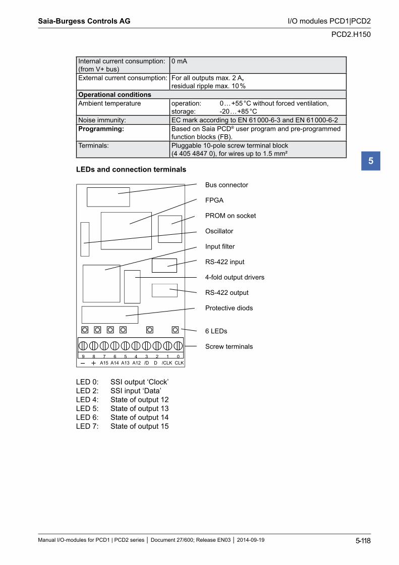
Saia-Burgess Controls AG
Manual I/O-modules for PCD1 | PCD2 series Document 27/600; Release EN03 2014-09-19 5-118
I/O modules PCD1|PCD2
PCD2.H150
5
Internal current consumption: (from V+ bus)
0 mA
External current consumption: For all outputs max. 2 A, residual ripple max. 10 %
Operational conditionsAmbient temperature operation: 0 … +55 °C without forced ventilation,
storage: -20 … +85 °CNoise immunity: EC mark according to EN 61 000-6-3 and EN 61 000-6-2Programming: Based on Saia PCD® user program and pre-programmed
function blocks (FB). Terminals: Pluggable 10-pole screw terminal block
(4 405 4847 0), for wires up to 1.5 mm²
LEDs and connection terminals
Bus connector
FPGA
PROM on socket
Oscillator
Input filter
RS-422 input
4-fold output drivers
RS-422 output
Protective diods
6 LEDs
Screw terminals 9 8 7 6 5 4 3 2 1 0
A12A13 /D D /CLK CLKA14A15
LED 0: SSI output ‘Clock’ LED 2: SSI input ‘Data’ LED 4: State of output 12 LED 5: State of output 13 LED 6: State of output 14 LED 7: State of output 15
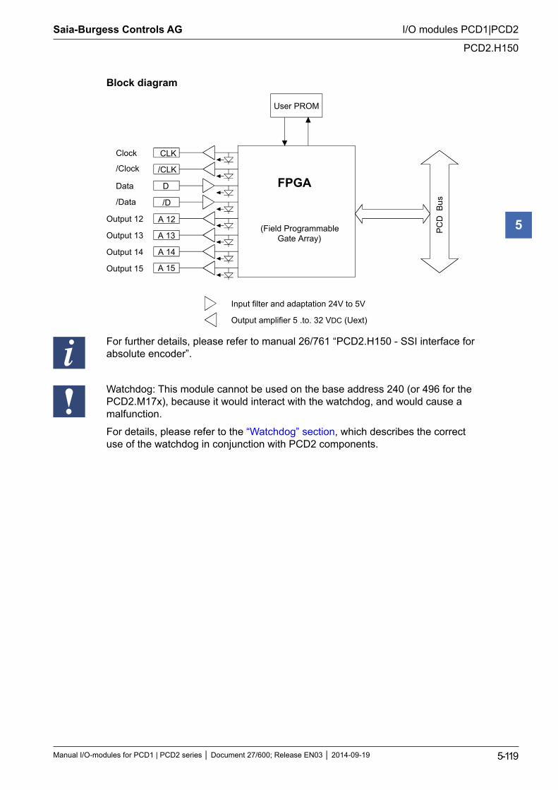
Saia-Burgess Controls AG
Manual I/O-modules for PCD1 | PCD2 series Document 27/600; Release EN03 2014-09-19 5-119
I/O modules PCD1|PCD2
PCD2.H150
5
Block diagram
CLK
/CLK
D
/D
A 12
A 13
User PROM
FPGA
(Field ProgrammableGate Array)
PC
D B
us
Input filter and adaptation 24V to 5V
Output amplifier 5 .to. 32 VDC (Uext)
Clock
/Clock
Data
/Data
Output 12
A 14
A 15
Output 13
Output 14
Output 15
For further details, please refer to manual 26/761 “PCD2.H150 - SSI interface for absolute encoder”.
Watchdog: This module cannot be used on the base address 240 (or 496 for the PCD2.M17x), because it would interact with the watchdog, and would cause a malfunction.
For details, please refer to the “Watchdog” section, which describes the correct use of the watchdog in conjunction with PCD2 components.
Saia-Burgess Controls AG
Manual I/O-modules for PCD1 | PCD2 series Document 27/600; Release EN03 2014-09-19 5-120
I/O modules PCD1|PCD2
Motion control modules for stepper motors
5
5.18 Motion control modules for stepper motors
PCD2.H210 Motion control module for stepper motors
I/O modules and I/O terminal blocks may only be plugged in and removed when the Saia PCD® and the external +24 V are disconnected from the power supply.
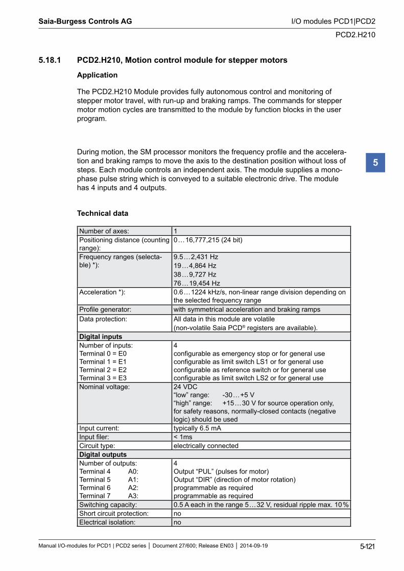
Saia-Burgess Controls AG
Manual I/O-modules for PCD1 | PCD2 series Document 27/600; Release EN03 2014-09-19 5-121
I/O modules PCD1|PCD2
PCD2.H210
5
5.18.1 PCD2.H210, Motion control module for stepper motors
Application
The PCD2.H210 Module provides fully autonomous control and monitoring of stepper motor travel, with run-up and braking ramps. The commands for stepper motor motion cycles are transmitted to the module by function blocks in the user program.
During motion, the SM processor monitors the frequency profile and the accelera-tion and braking ramps to move the axis to the destination position without loss of steps. Each module controls an independent axis. The module supplies a mono-phase pulse string which is conveyed to a suitable electronic drive. The module has 4 inputs and 4 outputs.
Technical data
Number of axes: 1Positioning distance (counting range):
0 … 16,777,215 (24 bit)
Frequency ranges (selecta-ble) *):
9.5 … 2,431 Hz 19 … 4,864 Hz 38 … 9,727 Hz 76 … 19,454 Hz
Acceleration *): 0.6 … 1224 kHz/s, non-linear range division depending on the selected frequency range
Profile generator: with symmetrical acceleration and braking rampsData protection: All data in this module are volatile
(non-volatile Saia PCD® registers are available).Digital inputsNumber of inputs: Terminal 0 = E0 Terminal 1 = E1 Terminal 2 = E2 Terminal 3 = E3
4 configurable as emergency stop or for general use configurable as limit switch LS1 or for general use configurable as reference switch or for general use configurable as limit switch LS2 or for general use
Nominal voltage: 24 VDC “low” range: -30 … +5 V “high” range: +15 … 30 V for source operation only, for safety reasons, normally-closed contacts (negative logic) should be used
Input current: typically 6.5 mAInput filer: < 1msCircuit type: electrically connectedDigital outputsNumber of outputs: Terminal 4 A0: Terminal 5 A1: Terminal 6 A2: Terminal 7 A3:
4 Output “PUL” (pulses for motor) Output “DIR” (direction of motor rotation) programmable as required programmable as required
Switching capacity: 0.5 A each in the range 5 … 32 V, residual ripple max. 10 %Short circuit protection: noElectrical isolation: no
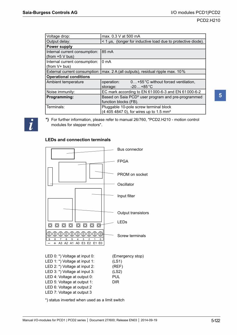
Saia-Burgess Controls AG
Manual I/O-modules for PCD1 | PCD2 series Document 27/600; Release EN03 2014-09-19 5-122
I/O modules PCD1|PCD2
PCD2.H210
5
Voltage drop: max. 0.3 V at 500 mAOutput delay: < 1 µs, (longer for inductive load due to protective diode).Power supplyInternal current consumption: (from +5 V bus)
85 mA
Internal current consumption: (from V+ bus)
0 mA
External current consumption: max. 2 A (all outputs), residual ripple max. 10 %Operational conditionsAmbient temperature operation: 0 … +55 °C without forced ventilation,
storage: -20 … +85 °CNoise immunity: EC mark according to EN 61 000-6-3 and EN 61 000-6-2Programming: Based on Saia PCD® user program and pre-programmed
function blocks (FB). Terminals: Pluggable 10-pole screw terminal block
(4 405 4847 0), for wires up to 1.5 mm²
*) For further information, please refer to manual 26/760, "PCD2.H210 - motion control modules for stepper motors".
LEDs and connection terminals
9 8 7 6 5 4 3 2 1 0A0A1 E3 E2 E1 E0A2A3
Bus connector
FPGA
PROM on socket
Oscillator
Input filter
Output transistors
LEDs
Screw terminals
LED 0: *) Voltage at input 0: (Emergency stop)LED 1: *) Voltage at input 1: (LS1) LED 2: *) Voltage at input 2: (REF)LED 3: *) Voltage at input 3: (LS2)LED 4: Voltage at output 0: PULLED 5: Voltage at output 1: DIRLED 6: Voltage at output 2LED 7: Voltage at output 3
*) status inverted when used as a limit switch
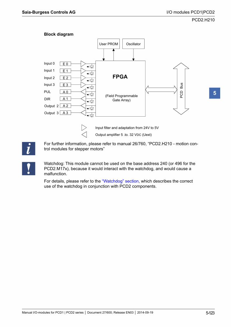
Saia-Burgess Controls AG
Manual I/O-modules for PCD1 | PCD2 series Document 27/600; Release EN03 2014-09-19 5-123
I/O modules PCD1|PCD2
PCD2.H210
5
Block diagram
E 0
E 1
E 2
E 3
A 0
A 1
User PROM Oscillator
FPGA
(Field ProgrammableGate Array)
PC
D B
us
Input filter and adaptation from 24V to 5V
Output amplifier 5 .to. 32 VDC (Uext)
Input 1
Input 2
Input 3
PUL
DIR
A 2
A 3
Output 2
Output 3
Input 0
For further information, please refer to manual 26/760, “PCD2.H210 - motion con-trol modules for stepper motors”
Watchdog: This module cannot be used on the base address 240 (or 496 for the PCD2.M17x), because it would interact with the watchdog, and would cause a malfunction.
For details, please refer to the “Watchdog” section, which describes the correct use of the watchdog in conjunction with PCD2 components.

Saia-Burgess Controls AG
Manual I/O-modules for PCD1 | PCD2 series Document 27/600; Release EN03 2014-09-19 5-124
I/O modules PCD1|PCD2
Motion control modules for servo-motors
5
5.19 Motion control modules for servo-motors
PCD2.H310 Motion control module for servo-motors, 1-axis encoder, 24 V
PCD2.H311 Motion control module for servo-motors, 1-axis encoder, 5 VPCD2.H320 Motion control module for servo-drives,
2-axis with 24 V encoderPCD2.H322 Motion control module for servo-drives,
1-axis with 24 V encoder (slave operation)PCD2.H325 Motion control module for servo-drives,
2-axis with 5 V and SSI absolute value encoderPCD2.H327 Motion control module for servo-drives, 1-axis with 5 V
encoder and SSI absolute value encoder (slave operation)
I/O modules and I/O terminal blocks may only be plugged in and removed when the Saia PCD® and the external +24 V are disconnected from the power supply.
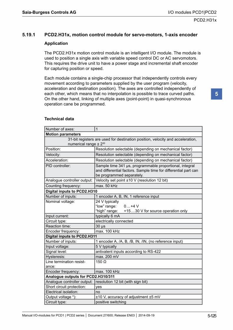
Saia-Burgess Controls AG
Manual I/O-modules for PCD1 | PCD2 series Document 27/600; Release EN03 2014-09-19 5-125
I/O modules PCD1|PCD2
PCD2.H31x
5
5.19.1 PCD2.H31x, motion control module for servo-motors, 1-axis encoder
Application
The PCD2.H31x motion control module is an intelligent I/O module. The module is used to position a single axis with variable speed control DC or AC servomotors. This requires the drive unit to have a power stage and incremental shaft encoder for capturing position or speed.
Each module contains a single-chip processor that independently controls every movement according to parameters supplied by the user program (velocity, acceleration and destination position). The axes are controlled independently of each other, which means that no interpolation is possible to trace curved paths. On the other hand, linking of multiple axes (point-point) in quasi-synchronous operation cane be programmed.
Technical data
Number of axes: 1Motion parameters
31-bit registers are used for destination position, velocity and acceleration, numerical range ± 230
Position: Resolution selectable (depending on mechanical factor)Velocity: Resolution selectable (depending on mechanical factor)Acceleration: Resolution selectable (depending on mechanical factor)PID controller: Sample time 341 µs, programmable proportional, integral
and differential factors. Sample time for differential part can be programmed separately.
Analogue controller output: Velocity set point ±10 V (resolution 12 bit)Counting frequency: max. 50 kHzDigital inputs to PCD2.H310Number of inputs: 1 encoder A, B, IN, 1 reference inputNominal voltage: 24 V typically
“low” range: 0 … +4 V “high” range: +15 … 30 V for source operation only
Input current: typically 6 mACircuit type: electrically connectedReaction time: 30 µsEncoder frequency: max. 100 kHzDigital inputs to PCD2.H311Number of inputs: 1 encoder A, /A, B, /B, IN, /IN, (no reference input)Input voltage: 5 V typicallySignal level: antivalent inputs according to RS-422Hysteresis: max. 200 mVLine termination resist-ance:
150 Ω
Encoder frequency: max. 100 kHzAnalogue outputs for PCD2.H310/311Analogue controller output: resolution 12 bit (with sign bit)Short circuit protection: yesElectrical isolation: noOutput voltage *): ±10 V, accuracy of adjustment ±5 mVCircuit type: positive switching

Saia-Burgess Controls AG
Manual I/O-modules for PCD1 | PCD2 series Document 27/600; Release EN03 2014-09-19 5-126
I/O modules PCD1|PCD2
PCD2.H31x
5
Minimum load impedance: 3 kΩ*) Balancing output voltage is carried out in the factory. The user is strongly advised not to adjust the tuning potentiometer.5 V supply for 5 V encoder for PCD2.H3115 V output: 5 V supply of encoderShort circuit protection: yesElectrical isolation: noOutput voltage: 5 VMax. load current: 300 mAShort circuit current: 400 mA (this current also loads the PCD’s +5 V bus)Power supplyInternal current consump-tion: (from +5 V bus)
max. 140 mA typically 125 mA
Internal current consump-tion: (from V+ bus)
0 mA
External current consump-tion:
max. 15 mA, typically 10 mA, residual ripple max. 10 %
Operational conditionsAmbient temperature operation: 0 … +55 °C without forced ventilation,
storage: -20 … +85 °CNoise immunity: EC mark according to EN 61 000-6-3 and EN 61 000-6-2Programming: Based on Saia PCD® user program and pre-programmed
function blocks (FB). Terminals: Pluggable 10-pole screw terminal block
(4 405 4847 0), for wires up to 1.5 mm²
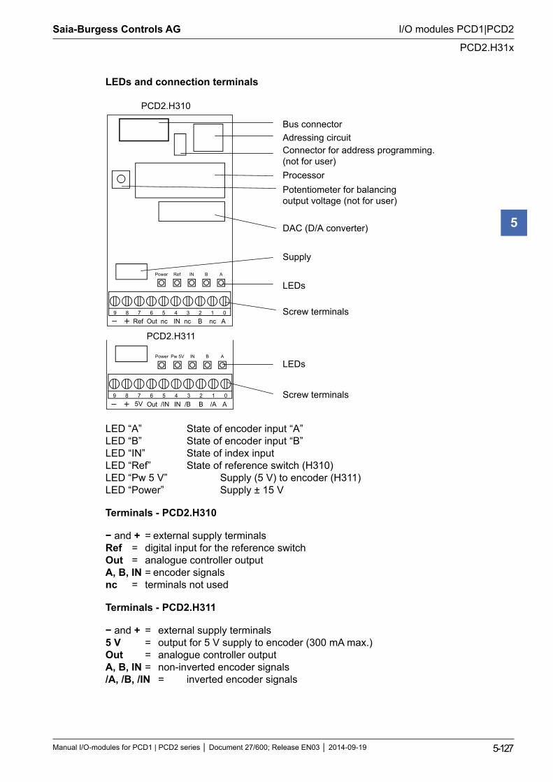
Saia-Burgess Controls AG
Manual I/O-modules for PCD1 | PCD2 series Document 27/600; Release EN03 2014-09-19 5-127
I/O modules PCD1|PCD2
PCD2.H31x
5
LEDs and connection terminals
9 8 7 6 5 4 3 2 1 0BINOut
Ref IN B APower
Ref nc Anc nc
Bus connector Adressing circuit Connector for address programming.(not for user) Processor Potentiometer for balancingoutput voltage (not for user)
DAC (D/A converter)
Supply
LEDs
Screw terminals
LEDs
Screw terminals 9 8 7 6 5 4 3 2 1 0BINOut
Pw 5V IN B APower
5V /IN A/B /A
PCD2.H310
PCD2.H311
LED “A” State of encoder input “A” LED “B” State of encoder input “B” LED “IN” State of index input LED “Ref” State of reference switch (H310) LED “Pw 5 V” Supply (5 V) to encoder (H311) LED “Power” Supply ± 15 V
Terminals - PCD2.H310
− and + = external supply terminals Ref = digital input for the reference switch Out = analogue controller output A, B, IN = encoder signals nc = terminals not used
Terminals - PCD2.H311
− and + = external supply terminals 5 V = output for 5 V supply to encoder (300 mA max.) Out = analogue controller output A, B, IN = non-inverted encoder signals /A, /B, /IN = inverted encoder signals
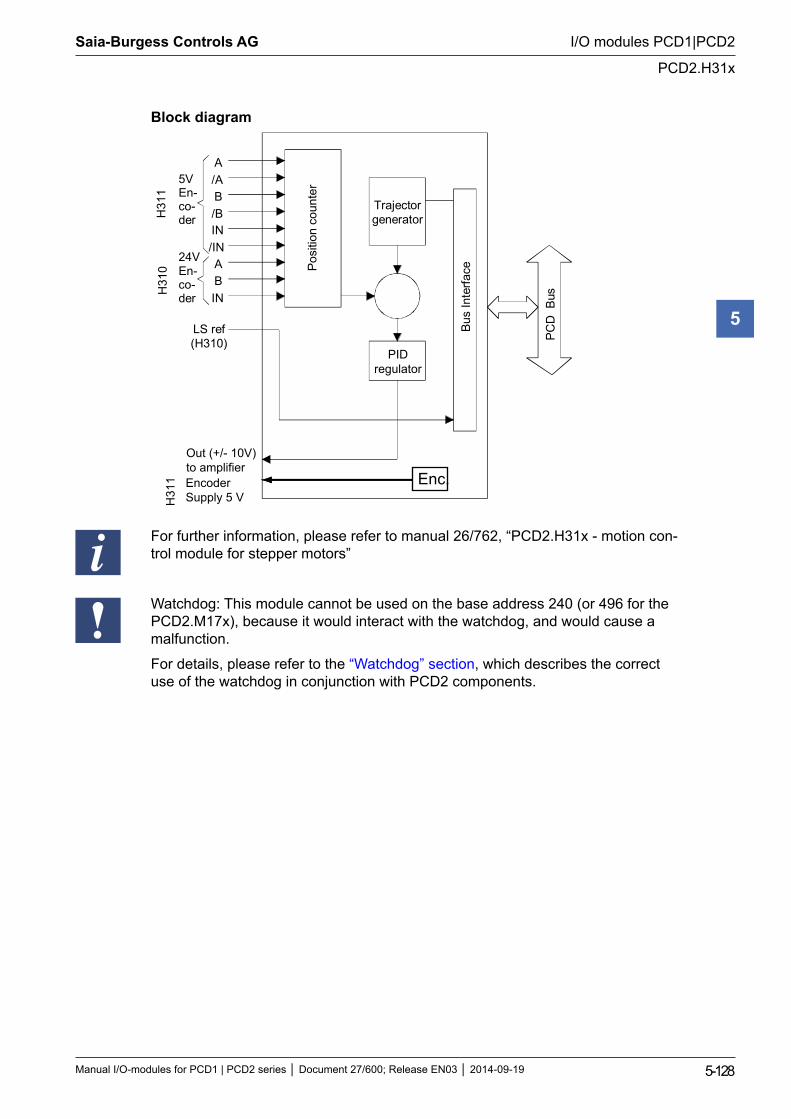
Saia-Burgess Controls AG
Manual I/O-modules for PCD1 | PCD2 series Document 27/600; Release EN03 2014-09-19 5-128
I/O modules PCD1|PCD2
PCD2.H31x
5
Block diagram
A/AB/B
/ININ
ABIN
5VEn-co-der
24VEn-co-der
LS ref(H310)
PIDregulator
Trajectorgenerator
Out (+/- 10V)to amplifier
Bus
Inte
rface
PCD
Bus
Pos
ition
cou
nter
H31
0H
311
EncoderSupply 5 VH
311 Enc.
For further information, please refer to manual 26/762, “PCD2.H31x - motion con-trol module for stepper motors”
Watchdog: This module cannot be used on the base address 240 (or 496 for the PCD2.M17x), because it would interact with the watchdog, and would cause a malfunction.
For details, please refer to the “Watchdog” section, which describes the correct use of the watchdog in conjunction with PCD2 components.
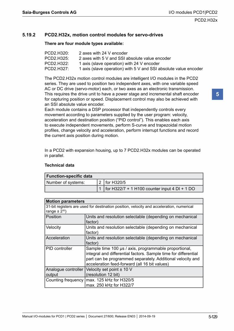
Saia-Burgess Controls AG
Manual I/O-modules for PCD1 | PCD2 series Document 27/600; Release EN03 2014-09-19 5-129
I/O modules PCD1|PCD2
PCD2.H32x
5
5.19.2 PCD2.H32x, motion control modules for servo-drives
There are four module types available:
PCD2.H320: 2 axes with 24 V encoder PCD2.H325: 2 axes with 5 V and SSI absolute value encoder PCD2.H322: 1 axis (slave operation) with 24 V encoder PCD2.H327: 1 axis (slave operation) with 5 V and SSI absolute value encoder
The PCD2.H32x motion control modules are intelligent I/O modules in the PCD2 series. They are used to position two independent axes, with one variable speed AC or DC drive (servo-motor) each, or two axes as an electronic transmission. This requires the drive unit to have a power stage and incremental shaft encoder for capturing position or speed. Displacement control may also be achieved with an SSI absolute value encoder. Each module contains a DSP processor that independently controls every movement according to parameters supplied by the user program: velocity, acceleration and destination position (“PID control”). This enables each axis to execute independent movements, perform S-curve and trapezoidal motion profiles, change velocity and acceleration, perform interrupt functions and record the current axis position during motion.
In a PCD2 with expansion housing, up to 7 PCD2.H32x modules can be operated in parallel.
Technical data
Function-specific dataNumber of systems: 2 for H320/5
1 for H322/7 + 1 H100 counter input 4 DI + 1 DO
Motion parameters31-bit registers are used for destination position, velocity and acceleration, numerical range ± 230)Position Units and resolution selectable (depending on mechanical
factor)Velocity Units and resolution selectable (depending on mechanical
factor)Acceleration Units and resolution selectable (depending on mechanical
factor)PID controller Sample time 100 µs / axis, programmable proportional,
integral and differential factors. Sample time for differential part can be programmed separately. Additional velocity and acceleration feed-forward (all 16 bit values)
Analogue controller output
Velocity set point ± 10 V (resolution 12 bit)
Counting frequency max. 125 kHz for H320/5 max. 250 kHz for H322/7
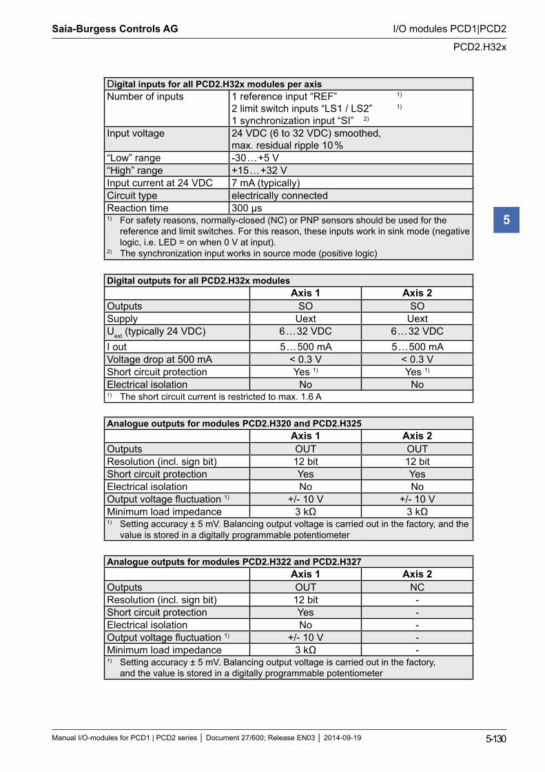
Saia-Burgess Controls AG
Manual I/O-modules for PCD1 | PCD2 series Document 27/600; Release EN03 2014-09-19 5-130
I/O modules PCD1|PCD2
PCD2.H32x
5
Digital inputs for all PCD2.H32x modules per axisNumber of inputs 1 reference input “REF” 1)
2 limit switch inputs “LS1 / LS2” 1) 1 synchronization input “SI” 2)
Input voltage 24 VDC (6 to 32 VDC) smoothed, max. residual ripple 10 %
“Low” range -30 … +5 V“High” range +15 … +32 VInput current at 24 VDC 7 mA (typically)Circuit type electrically connectedReaction time 300 µs1) For safety reasons, normally-closed (NC) or PNP sensors should be used for the
reference and limit switches. For this reason, these inputs work in sink mode (negative logic, i.e. LED = on when 0 V at input).
2) The synchronization input works in source mode (positive logic)
Digital outputs for all PCD2.H32x modulesAxis 1 Axis 2
Outputs SO SOSupply Uext UextUext (typically 24 VDC) 6 … 32 VDC 6 … 32 VDCI out 5 … 500 mA 5 … 500 mAVoltage drop at 500 mA < 0.3 V < 0.3 VShort circuit protection Yes 1) Yes 1)
Electrical isolation No No1) The short circuit current is restricted to max. 1.6 A
Analogue outputs for modules PCD2.H320 and PCD2.H325Axis 1 Axis 2
Outputs OUT OUTResolution (incl. sign bit) 12 bit 12 bitShort circuit protection Yes YesElectrical isolation No NoOutput voltage fluctuation 1) +/- 10 V +/- 10 VMinimum load impedance 3 kΩ 3 kΩ1) Setting accuracy ± 5 mV. Balancing output voltage is carried out in the factory, and the
value is stored in a digitally programmable potentiometer
Analogue outputs for modules PCD2.H322 and PCD2.H327Axis 1 Axis 2
Outputs OUT NCResolution (incl. sign bit) 12 bit -Short circuit protection Yes -Electrical isolation No -Output voltage fluctuation 1) +/- 10 V -Minimum load impedance 3 kΩ -1) Setting accuracy ± 5 mV. Balancing output voltage is carried out in the factory,
and the value is stored in a digitally programmable potentiometer
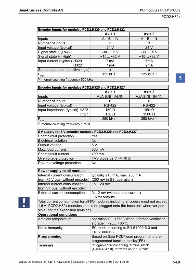
Saia-Burgess Controls AG
Manual I/O-modules for PCD1 | PCD2 series Document 27/600; Release EN03 2014-09-19 5-131
I/O modules PCD1|PCD2
PCD2.H32x
5
Encoder inputs for modules PCD2.H320 and PCD2.H322Axis 1 Axis 2
Inputs A B IN A B INNumber of inputs 3 3Input voltage (typical) 24 V 24 VSignal state L (Low) -30 … +5 V -30 … +5 VSignal state H (High) +15 … +32 V +15 … +32 VInput current (typical) H320 H322
7 mA 7 mA
7mA 2mA
Source operation (positive logic) x xFmax 125 kHz 1) 125 kHz 1)
1) Internal counting frequency 500 kHz
Encoder inputs for modules PCD2.H325 and PCD2.H327Axis 1 Axis 2
Inputs A,/A B,/B IN,/IN A,/A B,/B IN,/INNumber of inputs 6 6Input voltage (typical) RS-422 RS-422Input impedance (typical) H325 H327
150 Ω 150 Ω
150 Ω 1500 Ω
Fmax 250 kHz 1) 250 kHz 1)
1) Internal counting frequency 1 MHz
5 V supply for 5 V encoder modules PCD2.H325 and PCD2.H327Short circuit protection YesElectrical isolation NoOutput voltage 5 VMax. load current 300 mAShort circuit current 400 mAOvervoltage protection TVS diode 39 V +/- 10 %Reverse voltage protection No
Power supply to all modulesInternal current consumption: from +5 V bus (without encoder)
typically 210 mA, max. 230 mA (250 mA in SSI operation)
Internal current consumption: from V+ bus (without encoder)
15 … 20 mA
External current consumption: 0 … 2 mA (without load current) 1 A for outputs
Total current consumption for all I/O modules including encoders must not exceed 1.6 A. PCD2.H32x modules should be plugged onto the base unit wherever pos-sible (not the expansion housing).Operational conditionsAmbient temperature operation: 0 … +55 °C without forced ventilation,
storage: -20 … +85 °CNoise immunity: EC mark according to EN 61 000-6-3 and
EN 61 000-6-2Programming: Based on Saia PCD® user program and pre-
programmed function blocks (FB). Terminals: Pluggable 10-pole spring terminal block
(4 405 4847 0), for wires up to 1.5 mm²
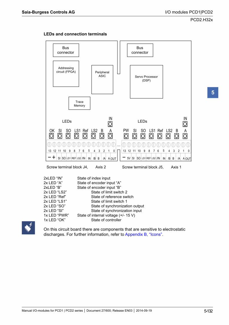
Saia-Burgess Controls AG
Manual I/O-modules for PCD1 | PCD2 series Document 27/600; Release EN03 2014-09-19 5-132
I/O modules PCD1|PCD2
PCD2.H32x
5
LEDs and connection terminals
0 1 2 3 4 5 6 7 8 9 10 11 12 13
5V
OK SI SO LS1 Ref LS2 B A
IN
PW R
SI SO LS1 Ref LS2 B A
IN
LS2 /IN IN /B B /A A SI LS1 REF SO OUT LS2 /IN IN /B B /A A SI LS1 REF SO OUT
0 1 2 3 4 5 6 7 8 9 10 11 12 13
Screw terminal block J4, Axis 2 Screw terminal block J5, Axis 1
Trace Memory
Bus connector
Bus connector
Addressing circuit (FPGA)
Servo Processor (DSP)
Peripheral ASIC
LEDs LEDs
2xLED “IN” State of index input 2x LED “A” State of encoder input “A” 2xLED “B” State of encoder input “B” 2x LED “LS2” State of limit switch 2 2x LED “Ref” State of reference switch 2x LED “LS1” State of limit switch 1 2x LED “SO” State of synchronization output 2x LED “SI” State of synchronization input 1x LED “PWR” State of internal voltage (+/- 15 V) 1x LED “OK” State of controller
On this circuit board there are components that are sensitive to electrostatic discharges. For further information, refer to Appendix B, “Icons”.
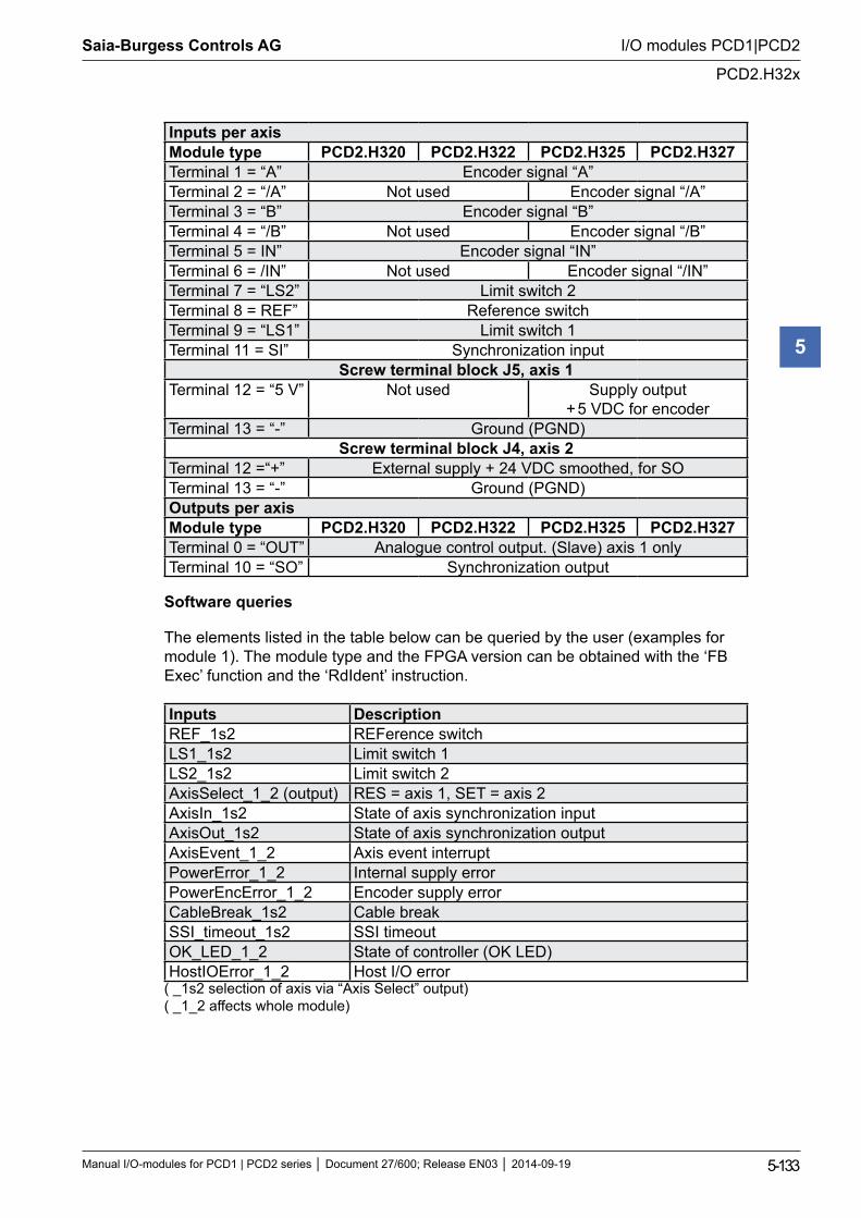
Saia-Burgess Controls AG
Manual I/O-modules for PCD1 | PCD2 series Document 27/600; Release EN03 2014-09-19 5-133
I/O modules PCD1|PCD2
PCD2.H32x
5
Inputs per axisModule type PCD2.H320 PCD2.H322 PCD2.H325 PCD2.H327Terminal 1 = “A” Encoder signal “A”Terminal 2 = “/A” Not used Encoder signal “/A”Terminal 3 = “B” Encoder signal “B”Terminal 4 = “/B” Not used Encoder signal “/B”Terminal 5 = IN” Encoder signal “IN”Terminal 6 = /IN” Not used Encoder signal “/IN”Terminal 7 = “LS2” Limit switch 2Terminal 8 = REF” Reference switchTerminal 9 = “LS1” Limit switch 1Terminal 11 = SI” Synchronization input
Screw terminal block J5, axis 1Terminal 12 = “5 V” Not used Supply output
+ 5 VDC for encoderTerminal 13 = “-” Ground (PGND)
Screw terminal block J4, axis 2Terminal 12 =“+” External supply + 24 VDC smoothed, for SOTerminal 13 = “-” Ground (PGND)Outputs per axis Module type PCD2.H320 PCD2.H322 PCD2.H325 PCD2.H327Terminal 0 = “OUT” Analogue control output. (Slave) axis 1 onlyTerminal 10 = “SO” Synchronization output
Software queries
The elements listed in the table below can be queried by the user (examples for module 1). The module type and the FPGA version can be obtained with the ‘FB Exec’ function and the ‘RdIdent’ instruction.
Inputs DescriptionREF_1s2 REFerence switchLS1_1s2 Limit switch 1LS2_1s2 Limit switch 2AxisSelect_1_2 (output) RES = axis 1, SET = axis 2AxisIn_1s2 State of axis synchronization inputAxisOut_1s2 State of axis synchronization outputAxisEvent_1_2 Axis event interruptPowerError_1_2 Internal supply errorPowerEncError_1_2 Encoder supply errorCableBreak_1s2 Cable breakSSI_timeout_1s2 SSI timeoutOK_LED_1_2 State of controller (OK LED) HostIOError_1_2 Host I/O error
( _1s2 selection of axis via “Axis Select” output) ( _1_2 affects whole module)
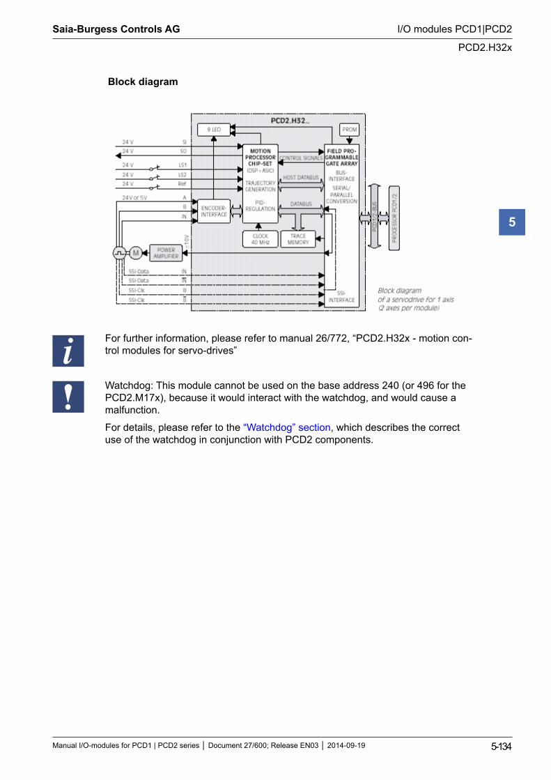
Saia-Burgess Controls AG
Manual I/O-modules for PCD1 | PCD2 series Document 27/600; Release EN03 2014-09-19 5-134
I/O modules PCD1|PCD2
PCD2.H32x
5
Block diagram
For further information, please refer to manual 26/772, “PCD2.H32x - motion con-trol modules for servo-drives”
Watchdog: This module cannot be used on the base address 240 (or 496 for the PCD2.M17x), because it would interact with the watchdog, and would cause a malfunction.
For details, please refer to the “Watchdog” section, which describes the correct use of the watchdog in conjunction with PCD2 components.
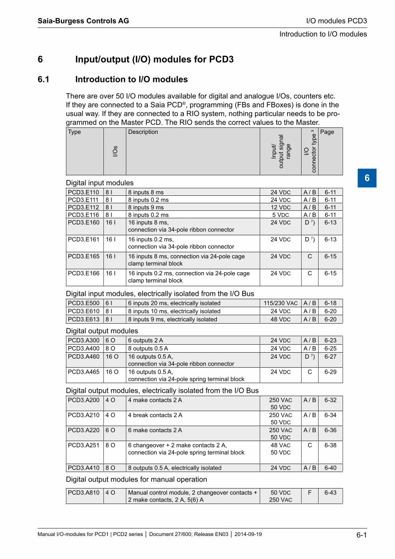
6 Input/output (I/O) modules for PCD3
6.1 Introduction to I/O modules
There are over 50 I/O modules available for digital and analogue I/Os, counters etc. If they are connected to a Saia PCD®, programming (FBs and FBoxes) is done in the usual way. If they are connected to a RIO system, nothing particular needs to be pro-grammed on the Master PCD. The RIO sends the correct values to the Master.Type
I/Os
Description
Inpu
t/ou
tput
sig
nal
rang
e
I/O
conn
ecto
r typ
e ³ Page
Digital input modulesPCD3.E110 8 I 8 inputs 8 ms 24 VDC A / B 6-11PCD3.E111 8 I 8 inputs 0.2 ms 24 VDC A / B 6-11PCD3.E112 8 I 8 inputs 9 ms 12 VDC A / B 6-11PCD3.E116 8 I 8 inputs 0.2 ms 5 VDC A / B 6-11PCD3.E160 16 I 16 inputs 8 ms,
connection via 34-pole ribbon connector24 VDC D 7) 6-13
PCD3.E161 16 I 16 inputs 0.2 ms, connection via 34-pole ribbon connector
24 VDC D 7) 6-13
PCD3.E165 16 I 16 inputs 8 ms, connection via 24-pole cage clamp terminal block
24 VDC C 6-15
PCD3.E166 16 I 16 inputs 0.2 ms, connection via 24-pole cage clamp terminal block
24 VDC C 6-15
Digital input modules, electrically isolated from the I/O Bus PCD3.E500 6 I 6 inputs 20 ms, electrically isolated 115/230 VAC A / B 6-18PCD3.E610 8 I 8 inputs 10 ms, electrically isolated 24 VDC A / B 6-20PCD3.E613 8 I 8 inputs 9 ms, electrically isolated 48 VDC A / B 6-20
Digital output modulesPCD3.A300 6 O 6 outputs 2 A 24 VDC A / B 6-23PCD3.A400 8 O 8 outputs 0.5 A 24 VDC A / B 6-25PCD3.A460 16 O 16 outputs 0.5 A,
connection via 34-pole ribbon connector24 VDC D 7) 6-27
PCD3.A465 16 O 16 outputs 0.5 A, connection via 24-pole spring terminal block
24 VDC C 6-29
Digital output modules, electrically isolated from the I/O BusPCD3.A200 4 O 4 make contacts 2 A 250 VAC
50 VDCA / B 6-32
PCD3.A210 4 O 4 break contacts 2 A 250 VAC 50 VDC
A / B 6-34
PCD3.A220 6 O 6 make contacts 2 A 250 VAC 50 VDC
A / B 6-36
PCD3.A251 8 O 6 changeover + 2 make contacts 2 A, connection via 24-pole spring terminal block
48 VAC 50 VDC
C 6-38
PCD3.A410 8 O 8 outputs 0.5 A, electrically isolated 24 VDC A / B 6-40
Digital output modules for manual operation
PCD3.A810 4 O Manual control module, 2 changeover contacts + 2 make contacts, 2 A, 5(6) A
50 VDC 250 VAC
F 6-43
Saia-Burgess Controls AG
Manual I/O-modules for PCD1 | PCD2 series Document 27/600; Release EN03 2014-09-19 6-1
I/O modules PCD3
Introduction to I/O modules
6
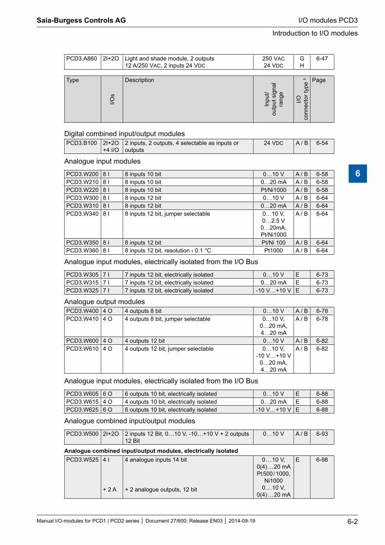
PCD3.A860 2I+2O Light and shade module, 2 outputs 12 A/250 VAC, 2 inputs 24 VDC
250 VAC 24 VDC
G H
6-47
Type
I/Os
Description
Inpu
t/ou
tput
sig
nal
rang
e
I/O
conn
ecto
r typ
e ³ Page
Digital combined input/output modules PCD3.B100 2I+2O
+4 I/O2 inputs, 2 outputs, 4 selectable as inputs or outputs
24 VDC A / B 6-54
Analogue input modules
PCD3.W200 8 I 8 inputs 10 bit 0…10 V A / B 6-58PCD3.W210 8 I 8 inputs 10 bit 0…20 mA A / B 6-58PCD3.W220 8 I 8 inputs 10 bit Pt/Ni1000 A / B 6-58PCD3.W300 8 I 8 inputs 12 bit 0…10 V A / B 6-64PCD3.W310 8 I 8 inputs 12 bit 0…20 mA A / B 6-64PCD3.W340 8 I 8 inputs 12 bit, jumper selectable 0…10 V,
0…2.5 V 0…20mA, Pt/Ni1000
A / B 6-64
PCD3.W350 8 I 8 inputs 12 bit Pt/Ni 100 A / B 6-64PCD3.W360 8 I 8 inputs 12 bit, resolution ‹ 0.1 °C Pt1000 A / B 6-64
Analogue input modules, electrically isolated from the I/O Bus
PCD3.W305 7 I 7 inputs 12 bit, electrically isolated 0…10 V E 6-73PCD3.W315 7 I 7 inputs 12 bit, electrically isolated 0…20 mA E 6-73PCD3.W325 7 I 7 inputs 12 bit, electrically isolated -10 V…+10 V E 6-73
Analogue output modulesPCD3.W400 4 O 4 outputs 8 bit 0…10 V A / B 6-78PCD3.W410 4 O 4 outputs 8 bit, jumper selectable 0…10 V,
0…20 mA, 4…20 mA
A / B 6-78
PCD3.W600 4 O 4 outputs 12 bit 0…10 V A / B 6-82PCD3.W610 4 O 4 outputs 12 bit, jumper selectable 0…10 V,
-10 V…+10 V 0…20 mA, 4…20 mA
A / B 6-82
Analogue input modules, electrically isolated from the I/O Bus
PCD3.W605 6 O 6 outputs 10 bit, electrically isolated 0…10 V E 6-88PCD3.W615 4 O 4 outputs 10 bit, electrically isolated 0…20 mA E 6-88PCD3.W625 6 O 6 outputs 10 bit, electrically isolated -10 V…+10 V E 6-88
Analogue combined input/output modules
PCD3.W500 2I+2O 2 inputs 12 Bit, 0…10 V, -10…+10 V + 2 outputs 12 Bit
0…10 V A / B 6-93
Analogue combined input/output modules, electrically isolated PCD3.W525 4 I
+ 2 A
4 analogue inputs 14 bit
+ 2 analogue outputs, 12 bit
0 … 10 V, 0(4) … 20 mA Pt 500 / 1000,
Ni1000 0 … 10 V,
0(4) … 20 mA
E 6-98
Saia-Burgess Controls AG
Manual I/O-modules for PCD1 | PCD2 series Document 27/600; Release EN03 2014-09-19 6-2
I/O modules PCD3
Introduction to I/O modules
6
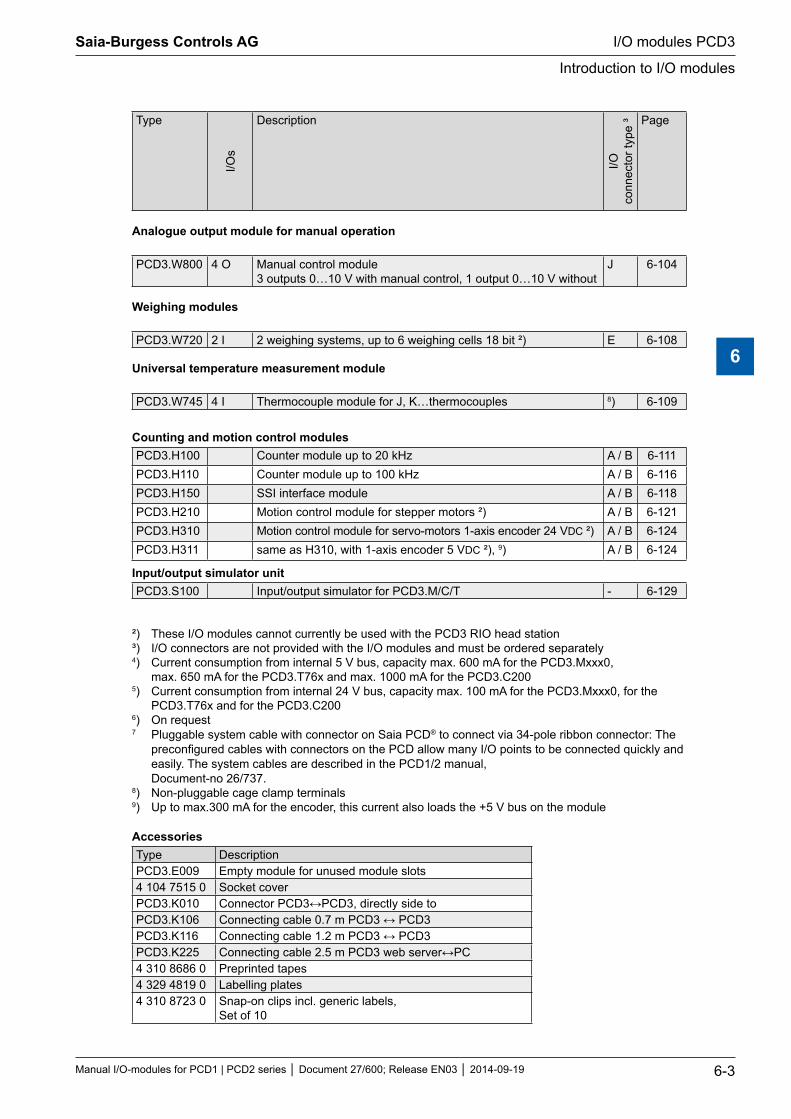
Type
I/Os
Description
I/O
conn
ecto
r typ
e ³ Page
Analogue output module for manual operation
PCD3.W800 4 O Manual control module 3 outputs 0…10 V with manual control, 1 output 0…10 V without
J 6-104
Weighing modules
PCD3.W720 2 I 2 weighing systems, up to 6 weighing cells 18 bit ²) E 6-108
Universal temperature measurement module
PCD3.W745 4 I Thermocouple module for J, K…thermocouples 8) 6-109
Counting and motion control modulesPCD3.H100 Counter module up to 20 kHz A / B 6-111PCD3.H110 Counter module up to 100 kHz A / B 6-116PCD3.H150 SSI interface module A / B 6-118PCD3.H210 Motion control module for stepper motors ²) A / B 6-121PCD3.H310 Motion control module for servo-motors 1-axis encoder 24 VDC ²) A / B 6-124PCD3.H311 same as H310, with 1-axis encoder 5 VDC ²), 9) A / B 6-124
Input/output simulator unit PCD3.S100 Input/output simulator for PCD3.M/C/T - 6-129
²) These I/O modules cannot currently be used with the PCD3 RIO head station ³) I/O connectors are not provided with the I/O modules and must be ordered separately 4) Current consumption from internal 5 V bus, capacity max. 600 mA for the PCD3.Mxxx0, max. 650 mA for the PCD3.T76x and max. 1000 mA for the PCD3.C200 5) Current consumption from internal 24 V bus, capacity max. 100 mA for the PCD3.Mxxx0, for the PCD3.T76x and for the PCD3.C200 6) On request 7 Pluggable system cable with connector on Saia PCD® to connect via 34-pole ribbon connector: The preconfigured cables with connectors on the PCD allow many I/O points to be connected quickly and easily. The system cables are described in the PCD1/2 manual, Document-no 26/737. 8) Non-pluggable cage clamp terminals 9) Up to max.300 mA for the encoder, this current also loads the +5 V bus on the module
AccessoriesType DescriptionPCD3.E009 Empty module for unused module slots4 104 7515 0 Socket coverPCD3.K010 Connector PCD3↔PCD3, directly side to PCD3.K106 Connecting cable 0.7 m PCD3 ↔ PCD3PCD3.K116 Connecting cable 1.2 m PCD3 ↔ PCD3PCD3.K225 Connecting cable 2.5 m PCD3 web server↔PC4 310 8686 0 Preprinted tapes4 329 4819 0 Labelling plates4 310 8723 0 Snap-on clips incl. generic labels,
Set of 10
Saia-Burgess Controls AG
Manual I/O-modules for PCD1 | PCD2 series Document 27/600; Release EN03 2014-09-19 6-3
I/O modules PCD3
Introduction to I/O modules
6
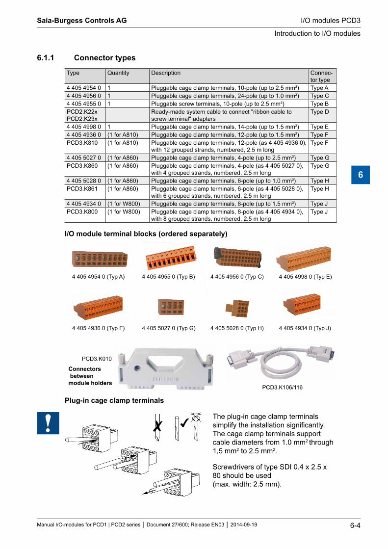
6.1.1 Connector types
Type Quantity Description Connec-tor type
4 405 4954 0 1 Pluggable cage clamp terminals, 10-pole (up to 2.5 mm²) Type A4 405 4956 0 1 Pluggable cage clamp terminals, 24-pole (up to 1.0 mm²) Type C4 405 4955 0 1 Pluggable screw terminals, 10-pole (up to 2.5 mm²) Type BPCD2.K22x PCD2.K23x
Ready-made system cable to connect "ribbon cable to screw terminal" adapters
Type D
4 405 4998 0 1 Pluggable cage clamp terminals, 14-pole (up to 1.5 mm²) Type E4 405 4936 0 (1 for A810) Pluggable cage clamp terminals, 12-pole (up to 1.5 mm²) Type FPCD3.K810 (1 for A810) Pluggable cage clamp terminals, 12-pole (as 4 405 4936 0),
with 12 grouped strands, numbered, 2.5 m longType F
4 405 5027 0 (1 for A860) Pluggable cage clamp terminals, 4-pole (up to 2.5 mm²) Type GPCD3.K860 (1 for A860) Pluggable cage clamp terminals, 4-pole (as 4 405 5027 0),
with 4 grouped strands, numbered, 2.5 m longType G
4 405 5028 0 (1 for A860) Pluggable cage clamp terminals, 6-pole (up to 1.0 mm²) Type HPCD3.K861 (1 for A860) Pluggable cage clamp terminals, 6-pole (as 4 405 5028 0),
with 6 grouped strands, numbered, 2.5 m longType H
4 405 4934 0 (1 for W800) Pluggable cage clamp terminals, 8-pole (up to 1.5 mm²) Type JPCD3.K800 (1 for W800) Pluggable cage clamp terminals, 8-pole (as 4 405 4934 0),
with 8 grouped strands, numbered, 2.5 m longType J
I/O module terminal blocks (ordered separately)
Connectors between module holders
Plug-in cage clamp terminals
The plug-in cage clamp terminals simplify the installation significantly. The cage clamp terminals support cable diameters from 1.0 mm2 through 1,5 mm2 to 2.5 mm2.
Screwdrivers of type SDI 0.4 x 2.5 x 80 should be used (max. width: 2.5 mm).
4 405 4954 0 (Typ A) 4 405 4955 0 (Typ B) 4 405 4956 0 (Typ C)
PCD3.K010
4 405 4998 0 (Typ E)
PCD3.K106/116
4 405 4936 0 (Typ F) 4 405 4934 0 (Typ J)4 405 5027 0 (Typ G) 4 405 5028 0 (Typ H)
Saia-Burgess Controls AG
Manual I/O-modules for PCD1 | PCD2 series Document 27/600; Release EN03 2014-09-19 6-4
I/O modules PCD3
Introduction to I/O modules
6
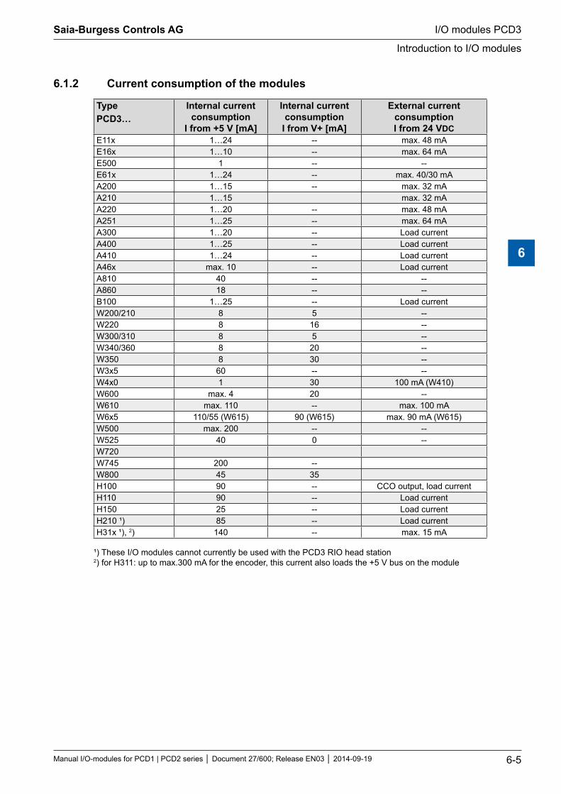
6.1.2 Current consumption of the modules
TypePCD3…
Internal current consumption
I from +5 V [mA]
Internal current consumption
I from V+ [mA]
External current consumptionI from 24 VDC
E11x 1…24 -- max. 48 mAE16x 1…10 -- max. 64 mAE500 1 -- --E61x 1…24 -- max. 40/30 mAA200 1…15 -- max. 32 mAA210 1…15 max. 32 mAA220 1…20 -- max. 48 mAA251 1…25 -- max. 64 mAA300 1…20 -- Load currentA400 1…25 -- Load currentA410 1…24 -- Load currentA46x max. 10 -- Load currentA810 40 -- --A860 18 -- --B100 1…25 -- Load currentW200/210 8 5 --W220 8 16 --W300/310 8 5 --W340/360 8 20 --W350 8 30 --W3x5 60 -- --W4x0 1 30 100 mA (W410)W600 max. 4 20 --W610 max. 110 -- max. 100 mAW6x5 110/55 (W615) 90 (W615) max. 90 mA (W615)W500 max. 200 -- --W525 40 0 --W720W745 200 --W800 45 35H100 90 -- CCO output, load currentH110 90 -- Load currentH150 25 -- Load currentH210 ¹) 85 -- Load currentH31x ¹), 2) 140 -- max. 15 mA
¹) These I/O modules cannot currently be used with the PCD3 RIO head station 2) for H311: up to max.300 mA for the encoder, this current also loads the +5 V bus on the module
Saia-Burgess Controls AG
Manual I/O-modules for PCD1 | PCD2 series Document 27/600; Release EN03 2014-09-19 6-5
I/O modules PCD3
Introduction to I/O modules
6
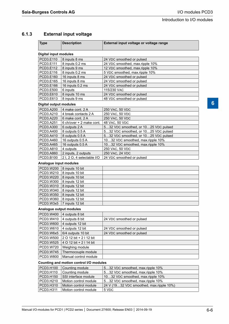
6.1.3 External input voltage
Type Description External input voltage or voltage range
Digital input modulesPCD3.E110 8 inputs 8 ms 24 VDC smoothed or pulsedPCD3.E111 8 inputs 0.2 ms 24 VDC smoothed, max.ripple 10%PCD3.E112 8 inputs 9 ms 12 VDC smoothed, max.ripple 10%PCD3.E116 8 inputs 0.2 ms 5 VDC smoothed, max.ripple 10%PCD3.E160 16 inputs 8 ms 24 VDC smoothed or pulsedPCD3.E165 16 inputs 8 ms 24 VDC smoothed or pulsedPCD3.E166 16 inputs 0.2 ms 24 VDC smoothed or pulsedPCD3.E500 6 inputs 115/230 VACPCD3.E610 8 inputs 10 ms 24 VDC smoothed or pulsedPCD3.E613 8 inputs 9 ms 48 VDC smoothed or pulsed
Digital output modulesPCD3.A200 4 make cont. 2 A 250 VAC, 50 VDCPCD3.A210 4 break contacts 2 A 250 VAC, 50 VDCPCD3.A220 6 make cont. 2 A 250 VAC, 50 VDCPCD3.A251 6 ch/over + 2 make cont. 48 VAC, 50 VDCPCD3.A300 6 outputs 2 A 5…32 VDC smoothed, or 10…25 VDC pulsedPCD3.A400 8 outputs 0.5 A 5…32 VDC smoothed, or 10…25 VDC pulsedPCD3.A410 8 outputs 0.5 A 5…32 VDC smoothed, or 10…25 VDC pulsedPCD3.A460 16 outputs 0.5 A 10…32 VDC smoothed, max.ripple 10%PCD3.A465 16 outputs 0.5 A 10…32 VDC smoothed, max.ripple 10%PCD3.A810 4 outputs 250 VAC, 50 VDCPCD3.A860 2 inputs, 2 outputs 250 VAC, 24 VDCPCD3.B100 2 I, 2 O, 4 selectable I/O 24 VDC smoothed or pulsed
Analogue input modulesPCD3.W200 8 inputs 10 bitPCD3.W210 8 inputs 10 bitPCD3.W220 8 inputs 10 bitPCD3.W300 8 inputs 12 bitPCD3.W310 8 inputs 12 bitPCD3.W340 8 inputs 12 bitPCD3.W350 8 inputs 12 bitPCD3.W360 8 inputs 12 bit PCD3.W3x5 7 inputs 12 bit
Analogue output modulesPCD3.W400 4 outputs 8 bitPCD3.W410 4 outputs 8 bit 24 VDC smoothed or pulsedPCD3.W600 4 outputs 12 bitPCD3.W610 4 outputs 12 bit 24 VDC smoothed or pulsedPCD3.W6x5 6/4 outputs 10 bit 24 VDC smoothed or pulsedPCD3.W500 2 O 12 bit + 2 I 12 bitPCD3.W525 4 O 12 bit + 2 I 14 bitPCD3.W720 Weighing module PCD3.W745 Thermocouple modulePCD3.W800 Manual control module
Counting and motion control I/O modulesPCD3.H100 Counting module 5…32 VDC smoothed, max.ripple 10%PCD3.H110 Counting module 5…32 VDC smoothed, max.ripple 10%PCD3.H150 SSI interface module 10…32 VDC smoothed, max.ripple 10%PCD3.H210 Motion control module 5…32 VDC smoothed, max.ripple 10%PCD3.H310 Motion control module 24 V (19…32 VDC smoothed, max.ripple 10%)PCD3.H311 Motion control module 5 VDC
Saia-Burgess Controls AG
Manual I/O-modules for PCD1 | PCD2 series Document 27/600; Release EN03 2014-09-19 6-6
I/O modules PCD3
Introduction to I/O modules
6
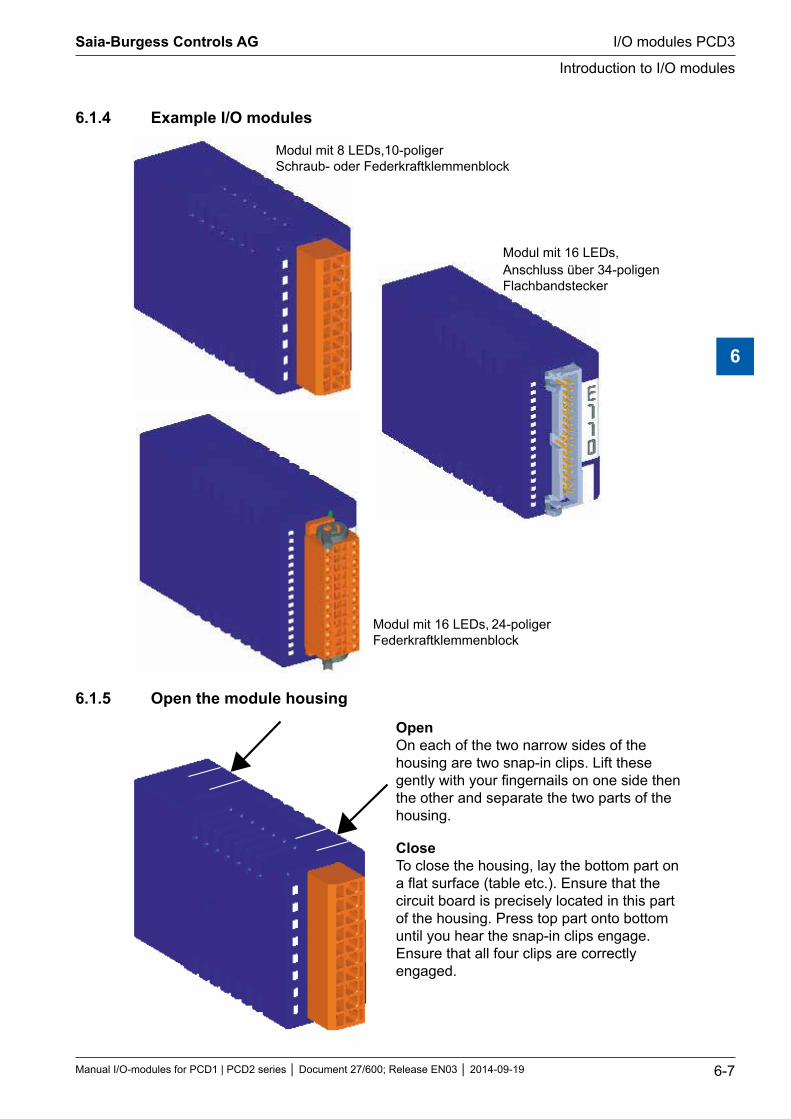
6.1.4 Example I/O modules
Modul mit 16 LEDs, 24-poliger Federkraftklemmenblock
Modul mit 16 LEDs,Anschluss über 34-poligenFlachbandstecker
Modul mit 8 LEDs, 10-poliger Schraub- oder Federkraftklemmenblock
6.1.5 Open the module housing
Open On each of the two narrow sides of the housing are two snap-in clips. Lift these gently with your fingernails on one side then the other and separate the two parts of the housing.
Close To close the housing, lay the bottom part on a flat surface (table etc.). Ensure that the circuit board is precisely located in this part of the housing. Press top part onto bottom until you hear the snap-in clips engage. Ensure that all four clips are correctly engaged.
Saia-Burgess Controls AG
Manual I/O-modules for PCD1 | PCD2 series Document 27/600; Release EN03 2014-09-19 6-7
I/O modules PCD3
Introduction to I/O modules
6
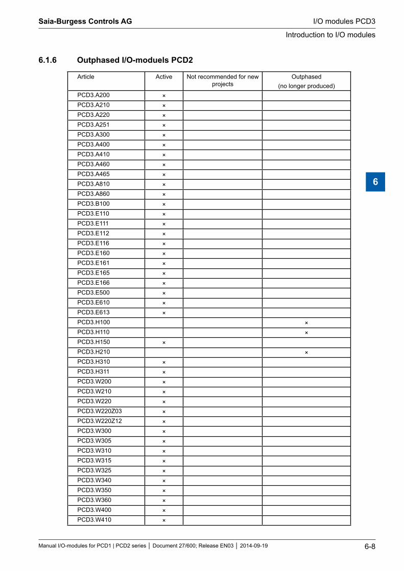
6.1.6 Outphased I/O-moduels PCD2
Article Active Not recommended for new projects
Outphased (no longer produced)
PCD3.A200 ×PCD3.A210 ×PCD3.A220 ×PCD3.A251 ×PCD3.A300 ×PCD3.A400 ×PCD3.A410 ×PCD3.A460 ×PCD3.A465 ×PCD3.A810 ×PCD3.A860 ×PCD3.B100 ×PCD3.E110 ×PCD3.E111 ×PCD3.E112 ×PCD3.E116 ×PCD3.E160 ×PCD3.E161 ×PCD3.E165 ×PCD3.E166 ×PCD3.E500 ×PCD3.E610 ×PCD3.E613 ×PCD3.H100 ×PCD3.H110 ×PCD3.H150 ×PCD3.H210 ×PCD3.H310 ×PCD3.H311 ×PCD3.W200 ×PCD3.W210 ×PCD3.W220 ×PCD3.W220Z03 ×PCD3.W220Z12 ×PCD3.W300 ×PCD3.W305 ×PCD3.W310 ×PCD3.W315 ×PCD3.W325 ×PCD3.W340 ×PCD3.W350 ×PCD3.W360 ×PCD3.W400 ×PCD3.W410 ×
Saia-Burgess Controls AG
Manual I/O-modules for PCD1 | PCD2 series Document 27/600; Release EN03 2014-09-19 6-8
I/O modules PCD3
Introduction to I/O modules
6
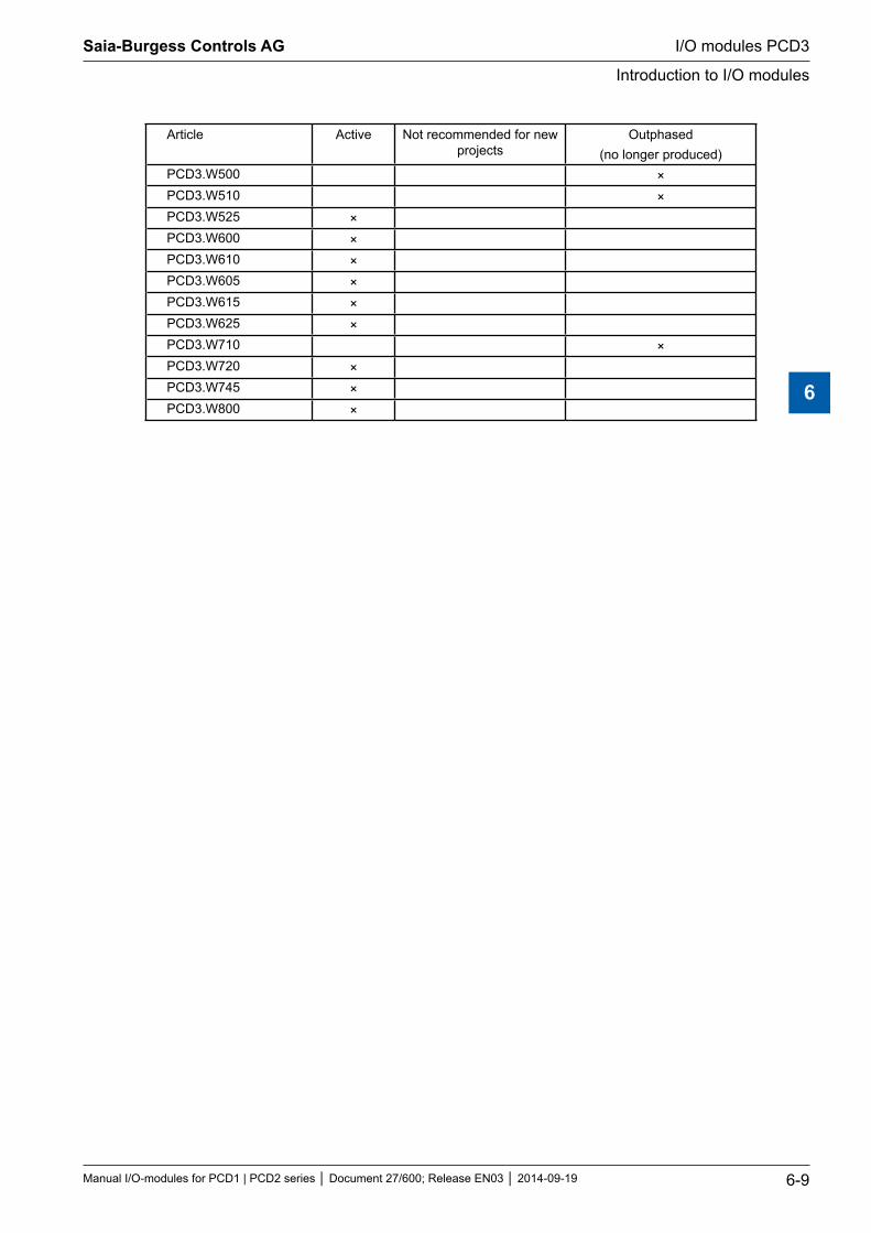
Article Active Not recommended for new projects
Outphased (no longer produced)
PCD3.W500 ×PCD3.W510 ×PCD3.W525 ×PCD3.W600 ×PCD3.W610 ×PCD3.W605 ×PCD3.W615 ×PCD3.W625 ×PCD3.W710 ×PCD3.W720 ×PCD3.W745 ×PCD3.W800 ×
Saia-Burgess Controls AG
Manual I/O-modules for PCD1 | PCD2 series Document 27/600; Release EN03 2014-09-19 6-9
I/O modules PCD3
Introduction to I/O modules
6
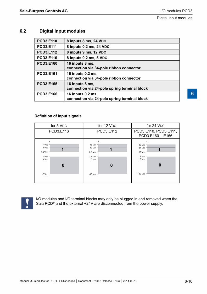
6.2 Digital input modules
PCD3.E110 8 inputs 8 ms, 24 VDCPCD3.E111 8 inputs 0.2 ms, 24 VDCPCD3.E112 8 inputs 9 ms, 12 VDCPCD3.E116 8 inputs 0.2 ms, 5 VDCPCD3.E160 16 inputs 8 ms,
connection via 34-pole ribbon connectorPCD3.E161 16 inputs 0.2 ms,
connection via 34-pole ribbon connectorPCD3.E165 16 inputs 8 ms,
connection via 24-pole spring terminal blockPCD3.E166 16 inputs 0.2 ms,
connection via 24-pole spring terminal block
Definition of input signals
for 5 VDC for 12 VDC for 24 VDC
PCD3.E116 PCD3.E112 PCD3.E110, PCD3.E111, PCD3.E160 … E166
7 VDC
5 VDC
2.5 VDC
0 VDC
1 VDC
-7 VDC
1
0
15 VDC
12 VDC
7.5 VDC
0 VDC
2.5 VDC
-15 VDC
1
0
30 VDC
24 VDC
15 VDC
0 VDC
5 VDC
-30 VDC
1
0
I/O modules and I/O terminal blocks may only be plugged in and removed when the Saia PCD® and the external +24V are disconnected from the power supply.
Saia-Burgess Controls AG
Manual I/O-modules for PCD1 | PCD2 series Document 27/600; Release EN03 2014-09-19 6-10
I/O modules PCD3
Digital input modules
6
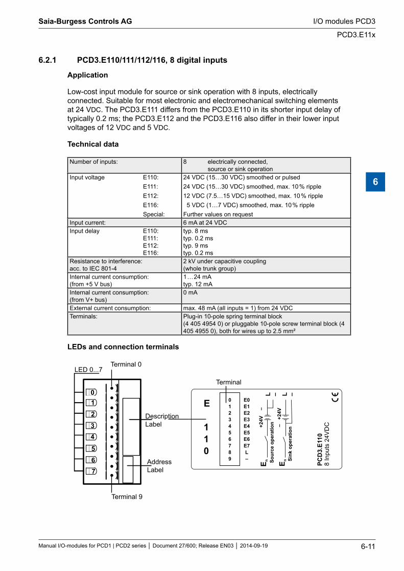
6.2.1 PCD3.E110/111/112/116, 8 digital inputs
Application
Low-cost input module for source or sink operation with 8 inputs, electrically connected. Suitable for most electronic and electromechanical switching elements at 24 VDC. The PCD3.E111 differs from the PCD3.E110 in its shorter input delay of typically 0.2 ms; the PCD3.E112 and the PCD3.E116 also differ in their lower input voltages of 12 VDC and 5 VDC.
Technical data
Number of inputs: 8 electrically connected, source or sink operation
Input voltage E110: E111: E112: E116: Special:
24 VDC (15…30 VDC) smoothed or pulsed24 VDC (15…30 VDC) smoothed, max. 10 % ripple12 VDC (7.5…15 VDC) smoothed, max. 10 % ripple 5 VDC (1…7 VDC) smoothed, max. 10 % rippleFurther values on request
Input current: 6 mA at 24 VDC Input delay E110: E111: E112: E116:
typ. 8 ms typ. 0.2 ms typ. 9 ms typ. 0.2 ms
Resistance to interference: acc. to IEC 801-4
2 kV under capacitive coupling (whole trunk group)
Internal current consumption: (from +5 V bus)
1 … 24 mA typ. 12 mA
Internal current consumption: (from V+ bus)
0 mA
External current consumption: max. 48 mA (all inputs = 1) from 24 VDCTerminals: Plug-in 10-pole spring terminal block
(4 405 4954 0) or pluggable 10-pole screw terminal block (4 405 4955 0), both for wires up to 2.5 mm²
LEDs and connection terminals
L – L –
E n Sour
ce o
pera
tion+2
4V
–
Sink
ope
ratio
nE n
– +
24V
PCD
3.E1
108
Inpu
ts 2
4VD
C
0123456789
E0E1E2E3E4E5E6E7L–
LED 0...7Terminal 0
DescriptionLabel
AddressLabel
Terminal 9
Terminal
E
110
01234
567
Saia-Burgess Controls AG
Manual I/O-modules for PCD1 | PCD2 series Document 27/600; Release EN03 2014-09-19 6-11
I/O modules PCD3
PCD3.E11x
6
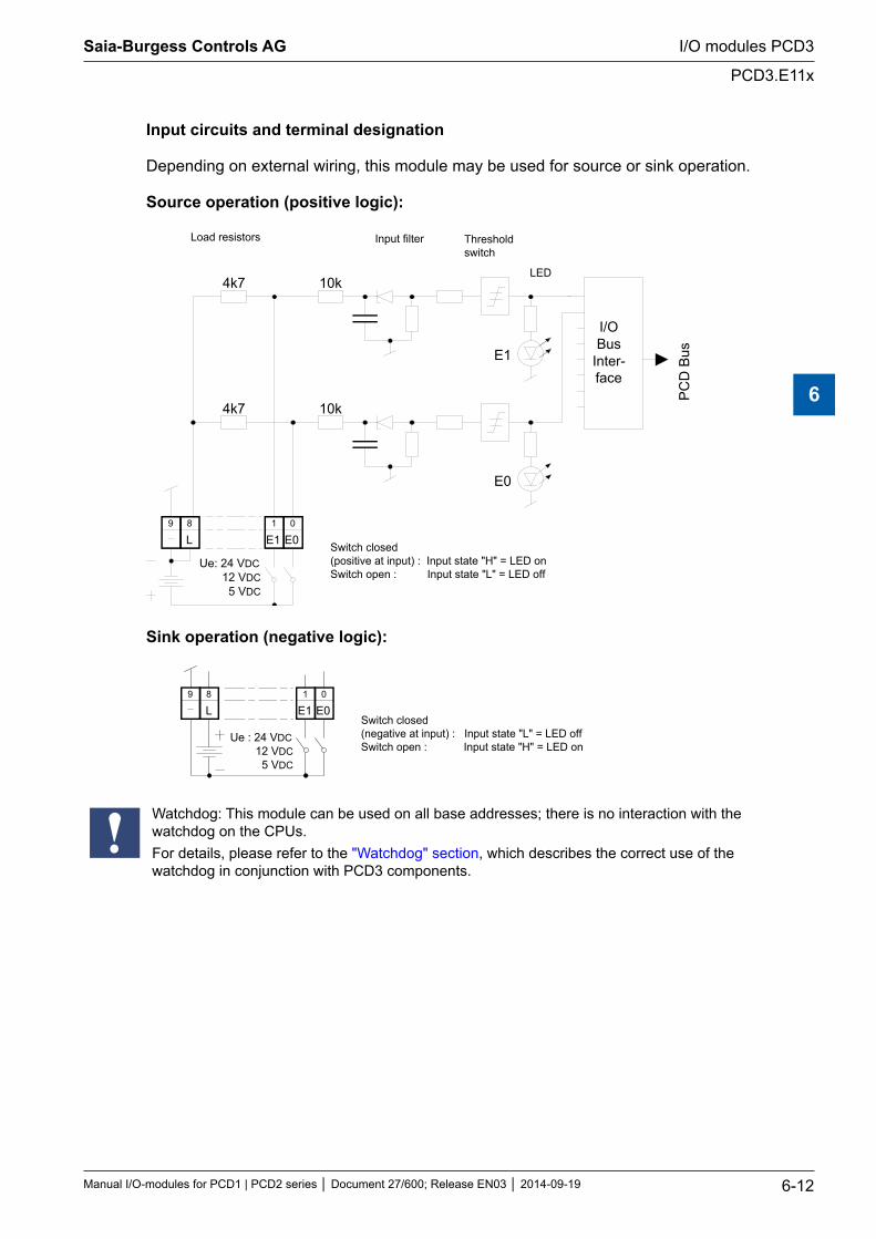
Input circuits and terminal designation
Depending on external wiring, this module may be used for source or sink operation.
Source operation (positive logic):
E0 0
E1 1
L 8 9
I/O Bus
Inter- face
PC
D B
us
E0
E1
4k7
4k7
10k
10k
Load resistors Input filter Threshold switch
LED
Switch closed (positive at input) : Input state "H" = LED on Switch open : Input state "L" = LED off
Ue: 24 VDC 12 VDC 5 VDC
Sink operation (negative logic):
E00
E11
L89
Switch closed(negative at input) : Input state "L" = LED offSwitch open : Input state "H" = LED on
Ue : 24 VDC 12 VDC 5 VDC
Watchdog: This module can be used on all base addresses; there is no interaction with the watchdog on the CPUs. For details, please refer to the "Watchdog" section, which describes the correct use of the watchdog in conjunction with PCD3 components.
Saia-Burgess Controls AG
Manual I/O-modules for PCD1 | PCD2 series Document 27/600; Release EN03 2014-09-19 6-12
I/O modules PCD3
PCD3.E11x
6
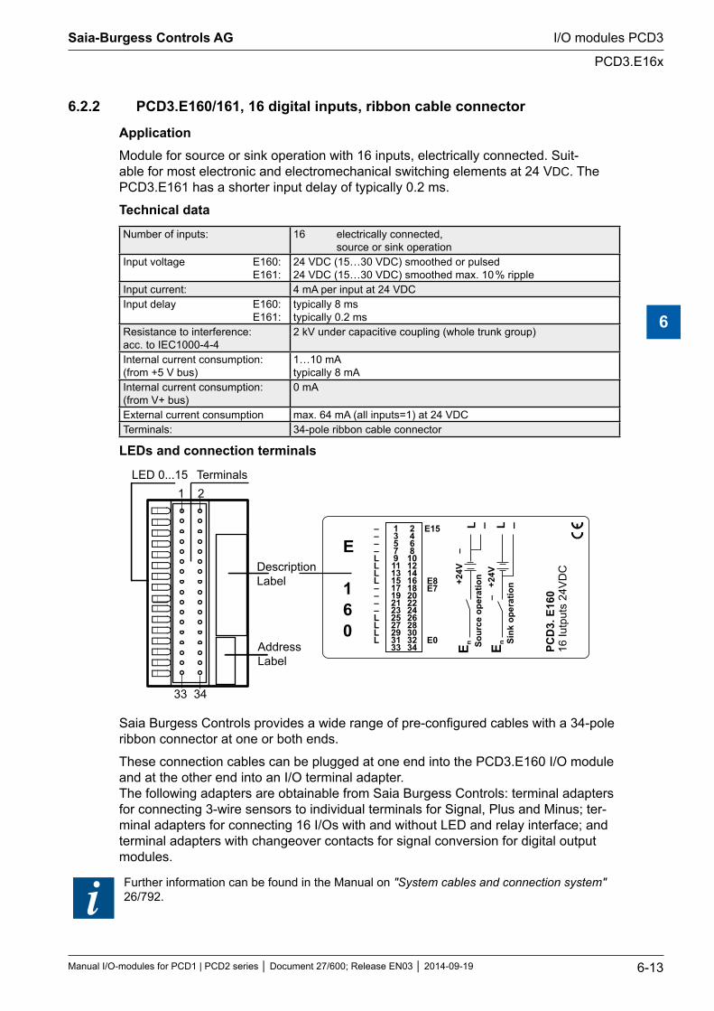
6.2.2 PCD3.E160/161, 16 digital inputs, ribbon cable connector
ApplicationModule for source or sink operation with 16 inputs, electrically connected. Suit-able for most electronic and electromechanical switching elements at 24 VDC. The PCD3.E161 has a shorter input delay of typically 0.2 ms.
Technical data
Number of inputs: 16 electrically connected, source or sink operation
Input voltage E160: E161:
24 VDC (15…30 VDC) smoothed or pulsed 24 VDC (15…30 VDC) smoothed max. 10 % ripple
Input current: 4 mA per input at 24 VDCInput delay E160: E161:
typically 8 ms typically 0.2 ms
Resistance to interference: acc. to IEC1000-4-4
2 kV under capacitive coupling (whole trunk group)
Internal current consumption: (from +5 V bus)
1…10 mA typically 8 mA
Internal current consumption: (from V+ bus)
0 mA
External current consumption max. 64 mA (all inputs=1) at 24 VDC Terminals: 34-pole ribbon cable connector
LEDs and connection terminals
PCD
3. E
160
16 Iu
tput
s 24
VD
C
13579111315171921232527293133
2468
10121416182022242628303234
––––LLLL––––LLLL
E15
E8E7
E0
L – L –
E n Sour
ce o
pera
tion+2
4V
–
Sink
ope
ratio
nE n
– +
24V
LED 0...15 Terminals
DescriptionLabel
AddressLabel
1 2
33 34
E
160
Saia Burgess Controls provides a wide range of pre-configured cables with a 34-pole ribbon connector at one or both ends.
These connection cables can be plugged at one end into the PCD3.E160 I/O module and at the other end into an I/O terminal adapter. The following adapters are obtainable from Saia Burgess Controls: terminal adapters for connecting 3-wire sensors to individual terminals for Signal, Plus and Minus; ter-minal adapters for connecting 16 I/Os with and without LED and relay interface; and terminal adapters with changeover contacts for signal conversion for digital output modules.
Further information can be found in the Manual on "System cables and connection system" 26/792.
Saia-Burgess Controls AG
Manual I/O-modules for PCD1 | PCD2 series Document 27/600; Release EN03 2014-09-19 6-13
I/O modules PCD3
PCD3.E16x
6
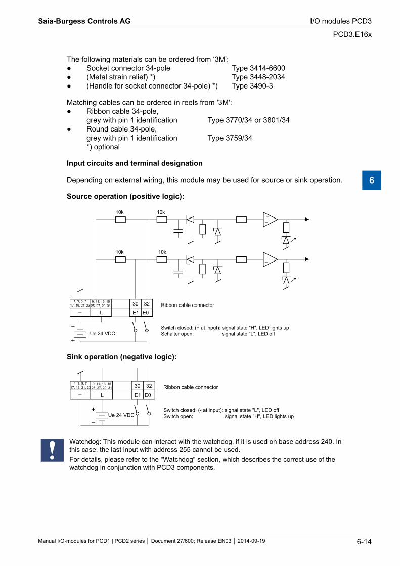
The following materials can be ordered from ‘3M’: Socket connector 34-pole Type 3414-6600 (Metal strain relief) *) Type 3448-2034 (Handle for socket connector 34-pole) *) Type 3490-3
Matching cables can be ordered in reels from '3M': Ribbon cable 34-pole, grey with pin 1 identification Type 3770/34 or 3801/34 Round cable 34-pole, grey with pin 1 identification Type 3759/34 *) optional
Input circuits and terminal designation
Depending on external wiring, this module may be used for source or sink operation.
Source operation (positive logic):
1, 3, 5, 717, 19, 21, 23
9, 11, 13, 1525, 27, 29, 31
L E1 E0
30 32
10k 10k
10k 10k
Ue 24 VDC
Ribbon cable connector
Switch closed: (+ at input): signal state "H", LED lights upSchalter open: signal state "L", LED off
Sink operation (negative logic):
1, 3, 5, 717, 19, 21, 23
9, 11, 13, 1525, 27, 29, 31
L E1 E0
30 32
Ue 24 VDC
Ribbon cable connector
Switch closed: (- at input): signal state "L", LED offSwitch open: signal state "H", LED lights up
Watchdog: This module can interact with the watchdog, if it is used on base address 240. In this case, the last input with address 255 cannot be used.For details, please refer to the "Watchdog" section, which describes the correct use of the watchdog in conjunction with PCD3 components.
Saia-Burgess Controls AG
Manual I/O-modules for PCD1 | PCD2 series Document 27/600; Release EN03 2014-09-19 6-14
I/O modules PCD3
PCD3.E16x
6
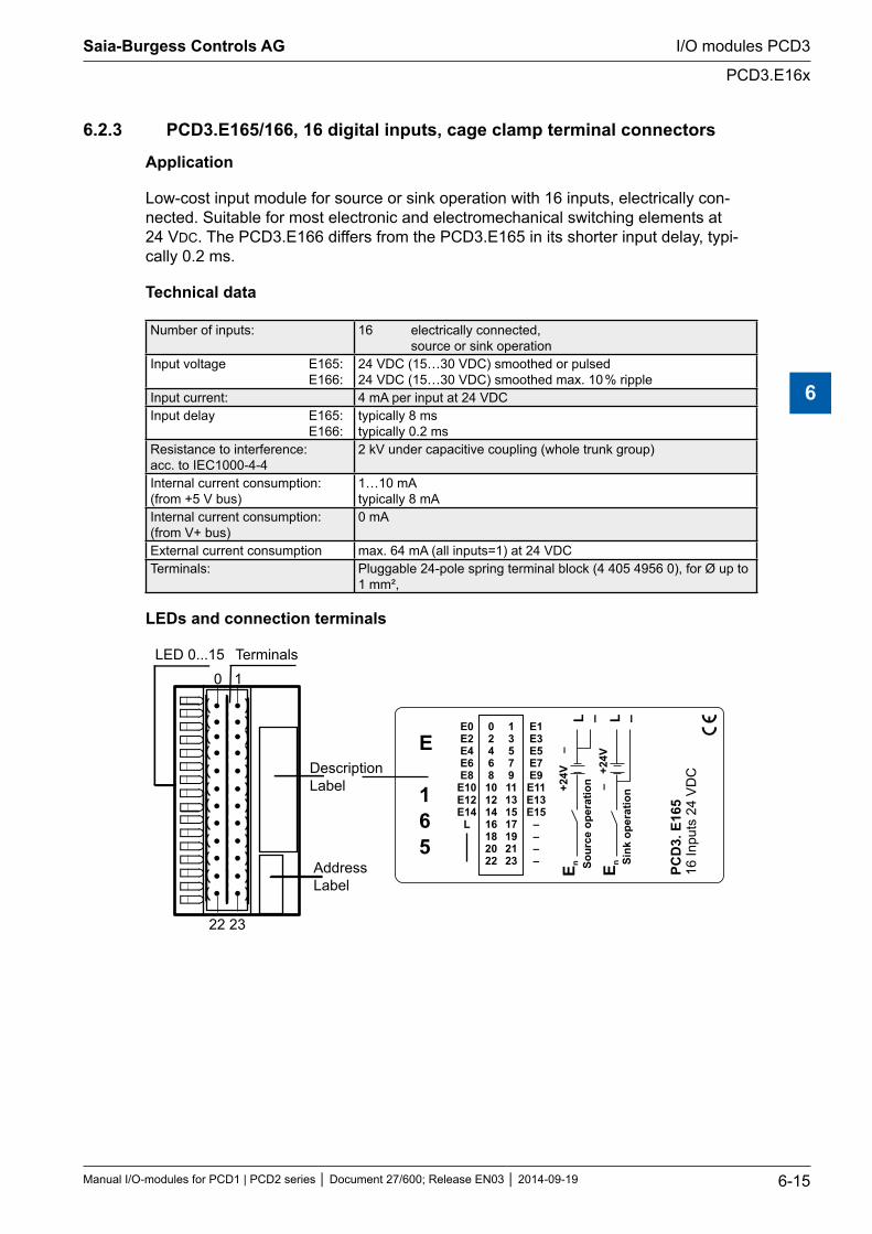
6.2.3 PCD3.E165/166, 16 digital inputs, cage clamp terminal connectors
Application
Low-cost input module for source or sink operation with 16 inputs, electrically con-nected. Suitable for most electronic and electromechanical switching elements at 24 VDC. The PCD3.E166 differs from the PCD3.E165 in its shorter input delay, typi-cally 0.2 ms.
Technical data
Number of inputs: 16 electrically connected, source or sink operation
Input voltage E165: E166:
24 VDC (15…30 VDC) smoothed or pulsed 24 VDC (15…30 VDC) smoothed max. 10 % ripple
Input current: 4 mA per input at 24 VDCInput delay E165: E166:
typically 8 ms typically 0.2 ms
Resistance to interference: acc. to IEC1000-4-4
2 kV under capacitive coupling (whole trunk group)
Internal current consumption: (from +5 V bus)
1…10 mA typically 8 mA
Internal current consumption: (from V+ bus)
0 mA
External current consumption max. 64 mA (all inputs=1) at 24 VDC Terminals: Pluggable 24-pole spring terminal block (4 405 4956 0), for Ø up to
1 mm²,
LEDs and connection terminals
PCD
3. E
165
16 In
puts
24
VD
C
1357911131517192123
0246810121416182022
E0E2E4E6E8
E10E12E14
L
E1E3E5E7E9E11E13E15
––––
L – L –
E n Sour
ce o
pera
tion+2
4V
–
Sink
ope
ratio
nE n
– +
24V
LED 0...15 Terminals
DescriptionLabel
AddressLabel
0 1
22 23
E
165
Saia-Burgess Controls AG
Manual I/O-modules for PCD1 | PCD2 series Document 27/600; Release EN03 2014-09-19 6-15
I/O modules PCD3
PCD3.E16x
6
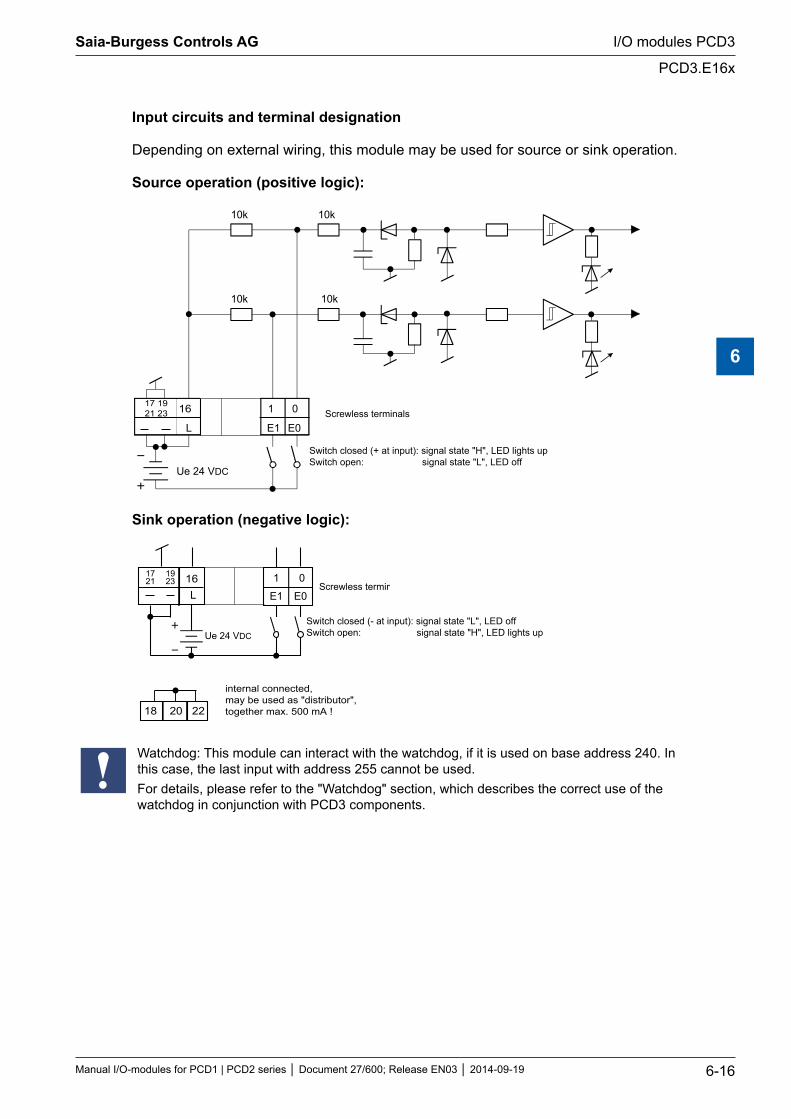
Input circuits and terminal designation
Depending on external wiring, this module may be used for source or sink operation.
Source operation (positive logic):
E1 E0
10k 10k
10k 10k
L
0117 1921 23 16
Ue 24 VDC
Switch closed (+ at input): signal state "H", LED lights upSwitch open: signal state "L", LED off
Screwless terminals
Sink operation (negative logic):
E1 E0
01L
16
18 20 22
1721
1923
Ue 24 VDC
Screwless terminals
Switch closed (- at input): signal state "L", LED offSwitch open: signal state "H", LED lights up
internal connected, may be used as "distributor",together max. 500 mA !
Watchdog: This module can interact with the watchdog, if it is used on base address 240. In this case, the last input with address 255 cannot be used.For details, please refer to the "Watchdog" section, which describes the correct use of the watchdog in conjunction with PCD3 components.
Saia-Burgess Controls AG
Manual I/O-modules for PCD1 | PCD2 series Document 27/600; Release EN03 2014-09-19 6-16
I/O modules PCD3
PCD3.E16x
6
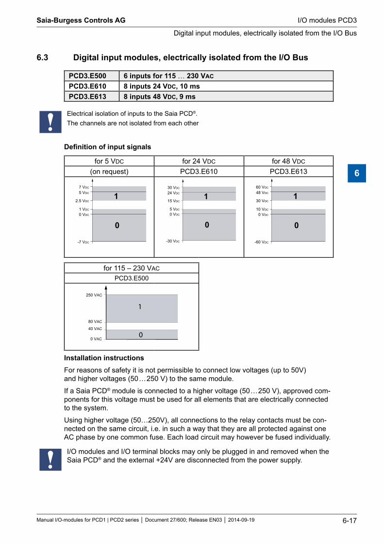
6.3 Digital input modules, electrically isolated from the I/O Bus
PCD3.E500 6 inputs for 115 … 230 VAC
PCD3.E610 8 inputs 24 VDC, 10 ms PCD3.E613 8 inputs 48 VDC, 9 ms
Electrical isolation of inputs to the Saia PCD®. The channels are not isolated from each other
Definition of input signals
for 5 VDC for 24 VDC for 48 VDC
(on request) PCD3.E610 PCD3.E613
7 VDC
5 VDC
2.5 VDC
0 VDC
1 VDC
-7 VDC
1
0
30 VDC
24 VDC
15 VDC
0 VDC
5 VDC
-30 VDC
1
0
60 VDC
48 VDC
30 VDC
0 VDC
10 VDC
-60 VDC
1
0
for 115 – 230 VAC
PCD3.E500
1
0
250 VAC
80 VAC
40 VAC
0 VAC
Installation instructionsFor reasons of safety it is not permissible to connect low voltages (up to 50V) and higher voltages (50 … 250 V) to the same module.
If a Saia PCD® module is connected to a higher voltage (50 … 250 V), approved com-ponents for this voltage must be used for all elements that are electrically connected to the system.
Using higher voltage (50…250V), all connections to the relay contacts must be con-nected on the same circuit, i.e. in such a way that they are all protected against one AC phase by one common fuse. Each load circuit may however be fused individually.
I/O modules and I/O terminal blocks may only be plugged in and removed when the Saia PCD® and the external +24V are disconnected from the power supply.
Saia-Burgess Controls AG
Manual I/O-modules for PCD1 | PCD2 series Document 27/600; Release EN03 2014-09-19 6-17
I/O modules PCD3
Digital input modules, electrically isolated from the I/O Bus
6
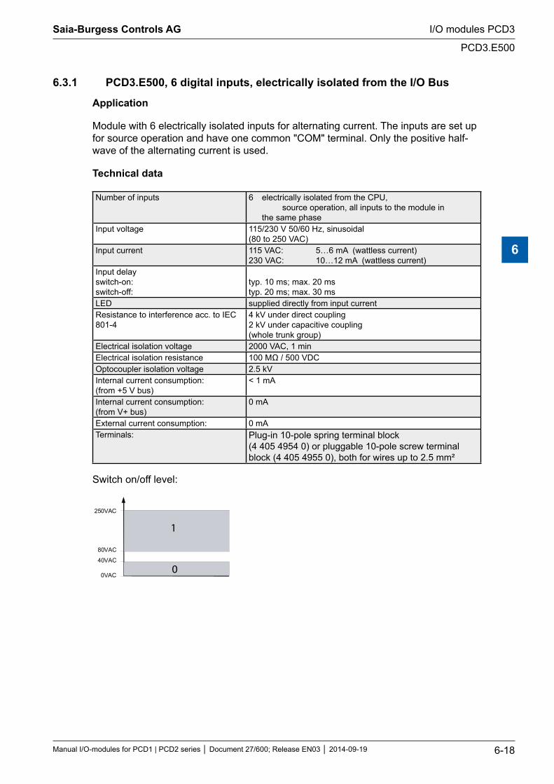
6.3.1 PCD3.E500, 6 digital inputs, electrically isolated from the I/O Bus
Application
Module with 6 electrically isolated inputs for alternating current. The inputs are set up for source operation and have one common "COM" terminal. Only the positive half-wave of the alternating current is used.
Technical data
Number of inputs 6 electrically isolated from the CPU, source operation, all inputs to the module in the same phase
Input voltage 115/230 V 50/60 Hz, sinusoidal (80 to 250 VAC)
Input current 115 VAC: 5…6 mA (wattless current) 230 VAC: 10…12 mA (wattless current)
Input delay switch-on: switch-off:
typ. 10 ms; max. 20 ms typ. 20 ms; max. 30 ms
LED supplied directly from input currentResistance to interference acc. to IEC 801-4
4 kV under direct coupling 2 kV under capacitive coupling (whole trunk group)
Electrical isolation voltage 2000 VAC, 1 minElectrical isolation resistance 100 MΩ / 500 VDCOptocoupler isolation voltage 2.5 kVInternal current consumption: (from +5 V bus)
< 1 mA
Internal current consumption: (from V+ bus)
0 mA
External current consumption: 0 mATerminals: Plug-in 10-pole spring terminal block
(4 405 4954 0) or pluggable 10-pole screw terminal block (4 405 4955 0), both for wires up to 2.5 mm²
Switch on/off level:
250VAC
80VAC
40VAC
0VAC
1
0
Saia-Burgess Controls AG
Manual I/O-modules for PCD1 | PCD2 series Document 27/600; Release EN03 2014-09-19 6-18
I/O modules PCD3
PCD3.E500
6
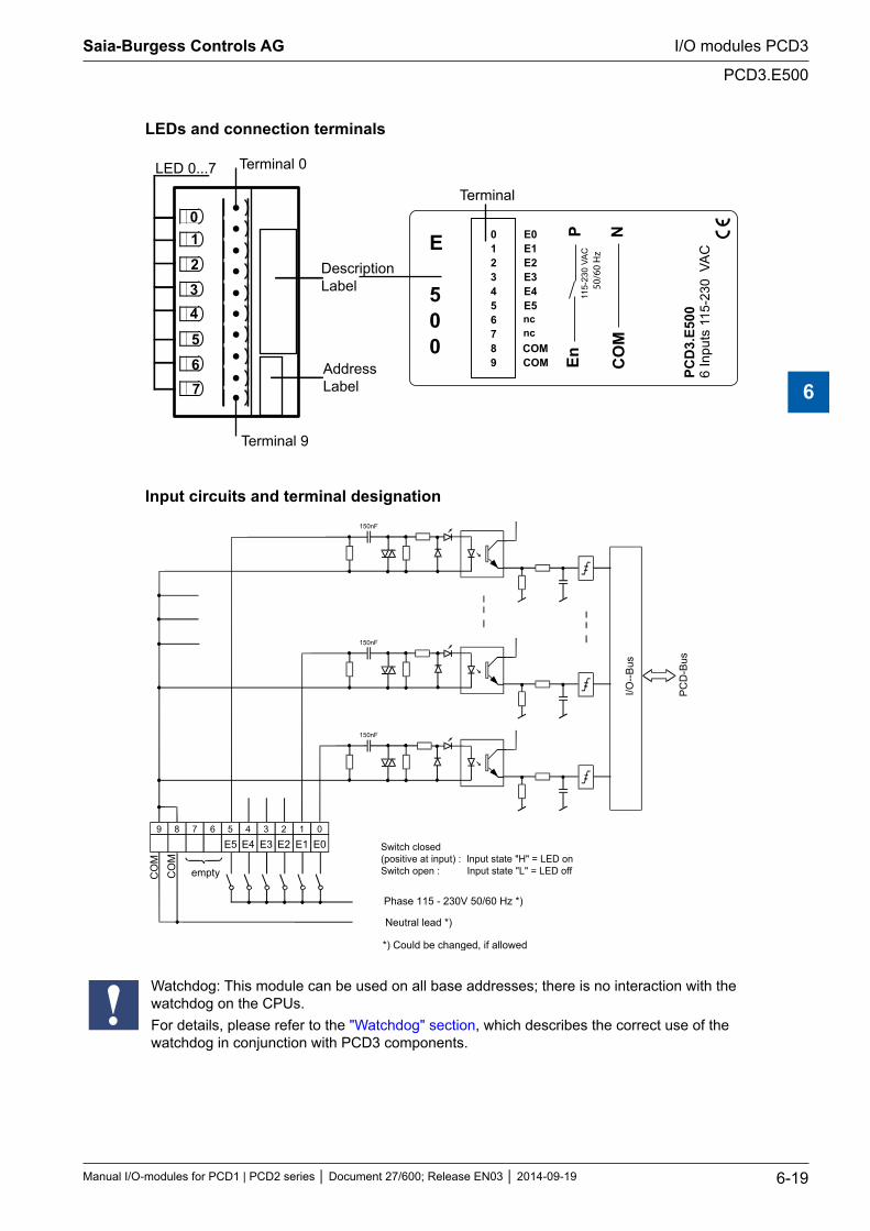
LEDs and connection terminals
En
PCD
3.E5
006
Inpu
ts 1
15-2
30VA
C 0
123456789
E0E1E2E3E4E5
COMCOM
LED 0...7
E
500
01234
567
CO
M
115-
230
VAC
ncnc
50/6
0 H
z
P N
Terminal 0
Terminal 9
Terminal
DescriptionLabel
AddressLabel
Input circuits and terminal designation
8 9 7 6 5
E5 4
E4 3
E3 2
E2 1
E1 0
E0
150nF
150nF
150nF
I/O--B
us
PC
D-B
us
empty
Phase 115 - 230V 50/60 Hz *)
Neutral lead *)
*) Could be changed, if allowed
CO
M
CO
M Switch closed(positive at input) : Input state "H" = LED onSwitch open : Input state "L" = LED off
Watchdog: This module can be used on all base addresses; there is no interaction with the watchdog on the CPUs. For details, please refer to the "Watchdog" section, which describes the correct use of the watchdog in conjunction with PCD3 components.
Saia-Burgess Controls AG
Manual I/O-modules for PCD1 | PCD2 series Document 27/600; Release EN03 2014-09-19 6-19
I/O modules PCD3
PCD3.E500
6
6.3.2 PCD3.E610/613, 8 digital inputs, electrically isolated from the I/O Bus
Application
Input module for source or sink operation with 8 inputs, electrically isolated by optocoupler. Suitable for most electronic and electromechanical switching elements at 24 VDC.
Technical data
Number of inputs: 8 electrically isolated by optocoupler, source or sink operation, all inputs to the model in the same phase
Input voltage E610: E613:
24 VDC (15…30 VDC) smoothed or pulsed 48 VDC (30…60 VDC) smoothed max. 10 % ripple
Supply voltage: for source operation: for sink operation:
E610: E613: min. 15 V 30 V min. 18 V 36 V
Input current: (at input voltage) for source operation: for sink operation:
E610: E613: (24 VDC) (48 VDC) 5 mA 2 mA 3.7 mA 1.5 mA
Input delay (0-1/1-0): E610: E613: incl. 10 ms 9 ms excl. 10 ms 9 ms
Resistance to interference: acc. to IEC 801-4
4 kV under direct coupling 2 kV under capacitive coupling (whole trunk group)
Electrical isolation voltage: Optocoupler isolation voltage:
1000 VAC, 1 min. 2.5 kV Electrical isolation of outputs to the Saia PCD®. The channels are not isolated from each other
Internal current consumption: (from +5 V bus)
1 … 24 mA typ. 12 mA
Internal current consumption: (from V+ bus)
0 mA
External current consumption: max. 40 mA (all inputs=1) at 24 VDC, (source operation), max. 18 mA (sink operation)
Terminals: Plug-in 10-pole spring terminal block (4 405 4954 0) or pluggable 10-pole screw terminal block (4 405 4955 0), both for wires up to 2.5 mm²
Saia-Burgess Controls AG
Manual I/O-modules for PCD1 | PCD2 series Document 27/600; Release EN03 2014-09-19 6-20
I/O modules PCD3
PCD3.E61x
6
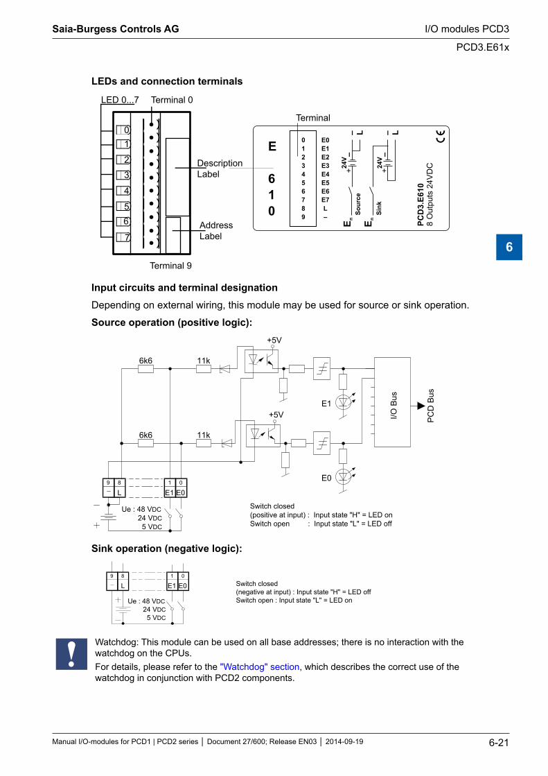
LEDs and connection terminals
01
2
3
4
56
7
LED 0...7 Terminal 0
DescriptionLabel
AddressLabel
PCD
3.E6
108
Out
puts
24V
DC
0123456789
E0E1E2E3E4E5E6E7L–
– LE n
Sour
ce
24V
+
–
– L
E nSi
nk24
V+
–
Terminal 9
Terminal
E
610
Input circuits and terminal designationDepending on external wiring, this module may be used for source or sink operation.
Source operation (positive logic):+5V
E0
E1
6k6
6k6
11k
11k
+5V
E0 E1 L 8 9 0 1
I/O B
us
Ue : 48 VDC 24 VDC 5 VDC
Switch closed (positive at input) : Input state "H" = LED on Switch open : Input state "L" = LED off
PC
D B
us
Sink operation (negative logic):
E0 E1 1
L 8 9 0
Switch closed (negative at input) : Input state "H" = LED off Switch open : Input state "L" = LED on Ue : 48 VDC
24 VDC 5 VDC
Watchdog: This module can be used on all base addresses; there is no interaction with the watchdog on the CPUs. For details, please refer to the "Watchdog" section, which describes the correct use of the watchdog in conjunction with PCD2 components.
Saia-Burgess Controls AG
Manual I/O-modules for PCD1 | PCD2 series Document 27/600; Release EN03 2014-09-19 6-21
I/O modules PCD3
PCD3.E61x
6
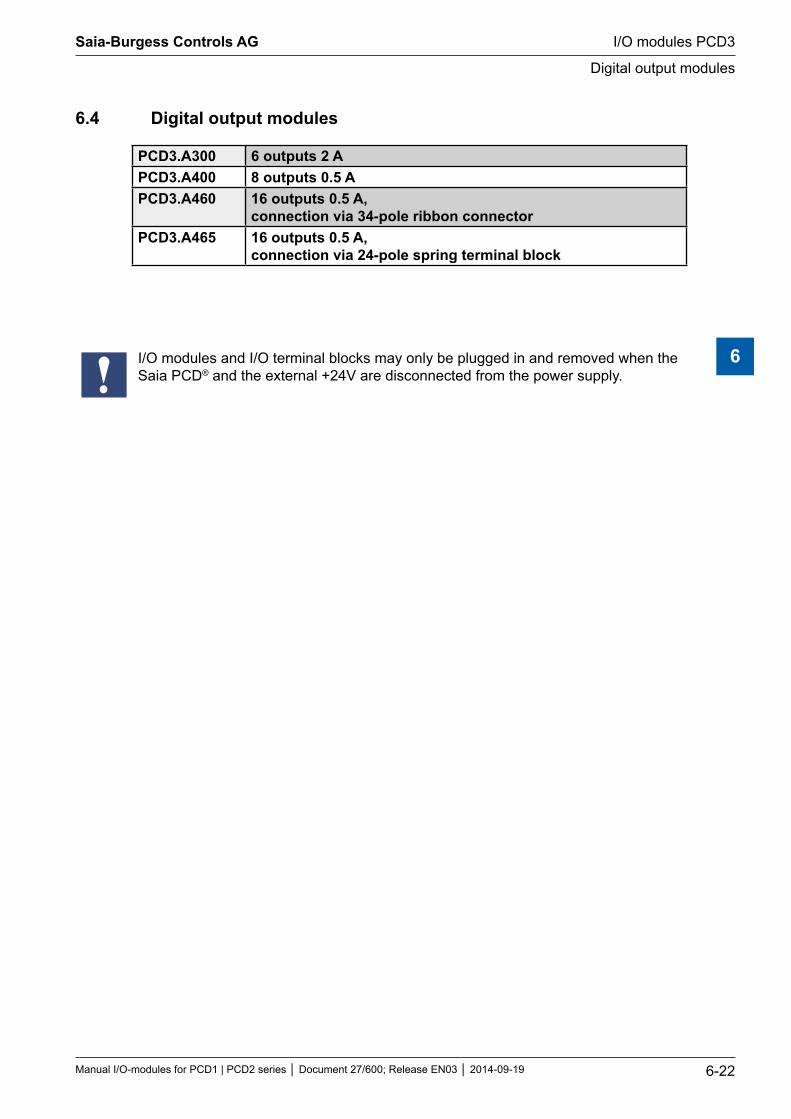
6.4 Digital output modules
PCD3.A300 6 outputs 2 APCD3.A400 8 outputs 0.5 APCD3.A460 16 outputs 0.5 A,
connection via 34-pole ribbon connectorPCD3.A465 16 outputs 0.5 A,
connection via 24-pole spring terminal block
I/O modules and I/O terminal blocks may only be plugged in and removed when the Saia PCD® and the external +24V are disconnected from the power supply.
Saia-Burgess Controls AG
Manual I/O-modules for PCD1 | PCD2 series Document 27/600; Release EN03 2014-09-19 6-22
I/O modules PCD3
Digital output modules
6
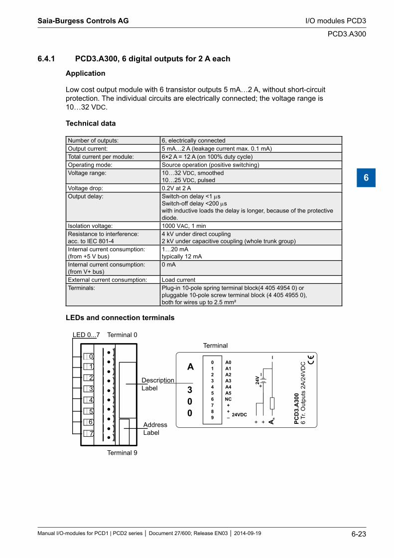
6.4.1 PCD3.A300, 6 digital outputs for 2 A each
Application
Low cost output module with 6 transistor outputs 5 mA…2 A, without short-circuit protection. The individual circuits are electrically connected; the voltage range is 10…32 VDC.
Technical data
Number of outputs: 6, electrically connectedOutput current: 5 mA…2 A (leakage current max. 0.1 mA)Total current per module: 6×2 A = 12 A (on 100% duty cycle)Operating mode: Source operation (positive switching)Voltage range: 10…32 VDC, smoothed
10…25 VDC, pulsedVoltage drop: 0.2V at 2 AOutput delay: Switch-on delay <1 µs
Switch-off delay <200 µs with inductive loads the delay is longer, because of the protective diode.
Isolation voltage: 1000 VAC, 1 minResistance to interference: acc. to IEC 801-4
4 kV under direct coupling 2 kV under capacitive coupling (whole trunk group)
Internal current consumption: (from +5 V bus)
1…20 mA typically 12 mA
Internal current consumption: (from V+ bus)
0 mA
External current consumption: Load currentTerminals: Plug-in 10-pole spring terminal block(4 405 4954 0) or
pluggable 10-pole screw terminal block (4 405 4955 0), both for wires up to 2.5 mm²
LEDs and connection terminals
01
2
3
4
56
7
LED 0...7 Terminal 0
DescriptionLabel
AddressLabel
24VDC
0123456789
A0A1A2A3A4A5NC++–
PCD
3.A
300
6Tr
. Out
puts
2A
/24V
DC
–
+ + An
24V
+
–
Terminal 9
Terminal
A
300
Saia-Burgess Controls AG
Manual I/O-modules for PCD1 | PCD2 series Document 27/600; Release EN03 2014-09-19 6-23
I/O modules PCD3
PCD3.A300
6
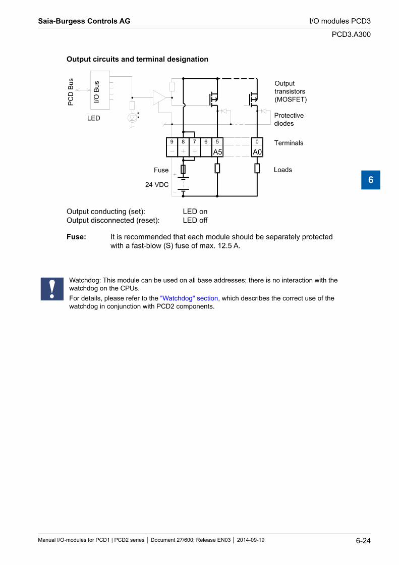
Output circuits and terminal designation
A0089 7
I/O B
us
PC
D B
us
24 VDC
Fuse
6 5
A5
Outputtransistors(MOSFET)
Protectivediodes
Terminals
Loads
LEDaddress A5
Output conducting (set): LED on Output disconnected (reset): LED off
Fuse: It is recommended that each module should be separately protected with a fast-blow (S) fuse of max. 12.5 A.
Watchdog: This module can be used on all base addresses; there is no interaction with the watchdog on the CPUs. For details, please refer to the "Watchdog" section, which describes the correct use of the watchdog in conjunction with PCD2 components.
Saia-Burgess Controls AG
Manual I/O-modules for PCD1 | PCD2 series Document 27/600; Release EN03 2014-09-19 6-24
I/O modules PCD3
PCD3.A300
6
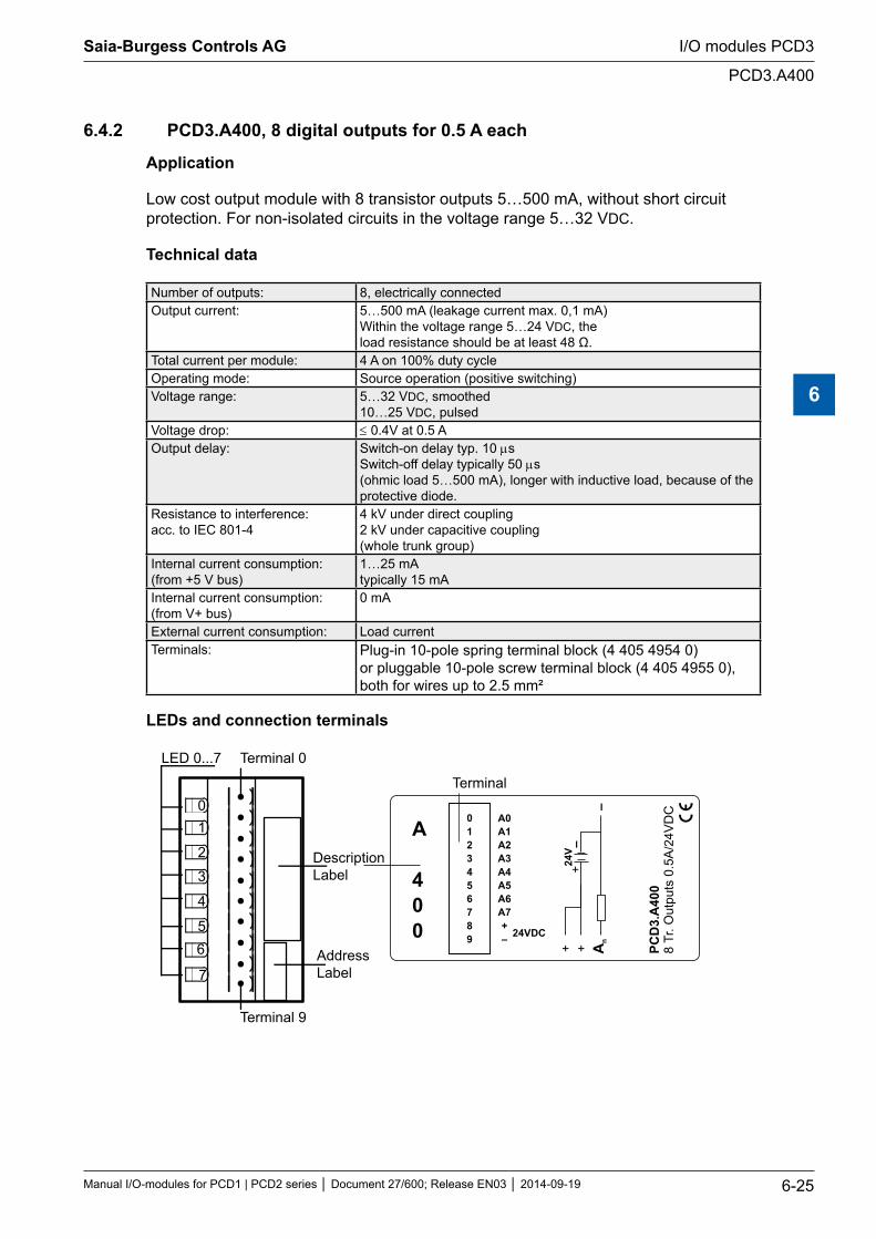
6.4.2 PCD3.A400, 8 digital outputs for 0.5 A each
Application
Low cost output module with 8 transistor outputs 5…500 mA, without short circuit protection. For non-isolated circuits in the voltage range 5…32 VDC.
Technical data
Number of outputs: 8, electrically connectedOutput current: 5…500 mA (leakage current max. 0,1 mA)
Within the voltage range 5…24 VDC, the load resistance should be at least 48 Ω.
Total current per module: 4 A on 100% duty cycle Operating mode: Source operation (positive switching)Voltage range: 5…32 VDC, smoothed
10…25 VDC, pulsedVoltage drop: ≤ 0.4V at 0.5 AOutput delay: Switch-on delay typ. 10 µs
Switch-off delay typically 50 µs (ohmic load 5…500 mA), longer with inductive load, because of the protective diode.
Resistance to interference: acc. to IEC 801-4
4 kV under direct coupling 2 kV under capacitive coupling (whole trunk group)
Internal current consumption: (from +5 V bus)
1…25 mA typically 15 mA
Internal current consumption: (from V+ bus)
0 mA
External current consumption: Load currentTerminals: Plug-in 10-pole spring terminal block (4 405 4954 0)
or pluggable 10-pole screw terminal block (4 405 4955 0), both for wires up to 2.5 mm²
LEDs and connection terminals
01
2
3
4
56
7
LED 0...7 Terminal 0
DescriptionLabel
AddressLabel
24VDC
0123456789
A0A1A2A3A4A5A6A7+–
PCD
3.A
400
8Tr
. Out
puts
0.5
A/2
4VD
C–
+ + An
24V
+
–
Terminal 9
Terminal
A
400
Saia-Burgess Controls AG
Manual I/O-modules for PCD1 | PCD2 series Document 27/600; Release EN03 2014-09-19 6-25
I/O modules PCD3
PCD3.A400
6
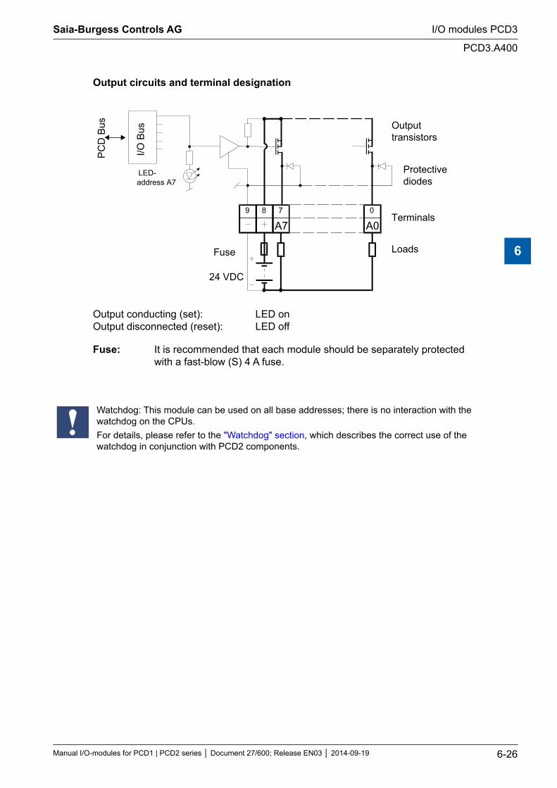
Output circuits and terminal designation
A0089 7
I/O B
us
PC
D B
us
24 VDC
Fuse
A7
Outputtransistors
Protectivediodes
Terminals
Loads
LED-address A7
Output conducting (set): LED on Output disconnected (reset): LED off
Fuse: It is recommended that each module should be separately protected with a fast-blow (S) 4 A fuse.
Watchdog: This module can be used on all base addresses; there is no interaction with the watchdog on the CPUs. For details, please refer to the "Watchdog" section, which describes the correct use of the watchdog in conjunction with PCD2 components.
Saia-Burgess Controls AG
Manual I/O-modules for PCD1 | PCD2 series Document 27/600; Release EN03 2014-09-19 6-26
I/O modules PCD3
PCD3.A400
6
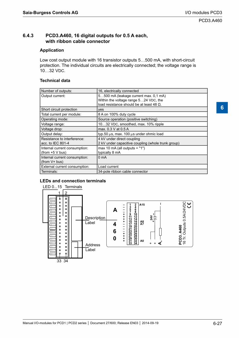
6.4.3 PCD3.A460, 16 digital outputs for 0.5 A each, with ribbon cable connector
Application
Low cost output module with 16 transistor outputs 5…500 mA, with short-circuit protection. The individual circuits are electrically connected; the voltage range is 10…32 VDC.
Technical data
Number of outputs: 16, electrically connectedOutput current: 5…500 mA (leakage current max. 0,1 mA)
Within the voltage range 5…24 VDC, the load resistance should be at least 48 Ω.
Short circuit protection yesTotal current per module: 8 A on 100% duty cycleOperating mode: Source operation (positive switching)Voltage range: 10…32 VDC, smoothed, max. 10% rippleVoltage drop: max. 0.3 V at 0.5 AOutput delay: typ.50 µs, max. 100 µs under ohmic loadResistance to interference: acc. to IEC 801-4
4 kV under direct coupling 2 kV under capacitive coupling (whole trunk group)
Internal current consumption: (from +5 V bus)
max 10 mA (all outputs = "1") typically 8 mA
Internal current consumption: (from V+ bus)
0 mA
External current consumption: Load currentTerminals: 34-pole ribbon cable connector
LEDs and connection terminalsLED 0...15 Terminals
DescriptionLabel
AddressLabel
PCD
3.A
460
16Tr
. Out
puts
0.5
A24
VD
C/
13579111315171921232527293133
246810121416182022242628303234
––––++++––––++++
A15
A8A7
A0
–
+ + An
24V
+
–
1 2
33 34
A
460
Saia-Burgess Controls AG
Manual I/O-modules for PCD1 | PCD2 series Document 27/600; Release EN03 2014-09-19 6-27
I/O modules PCD3
PCD3.A460
6
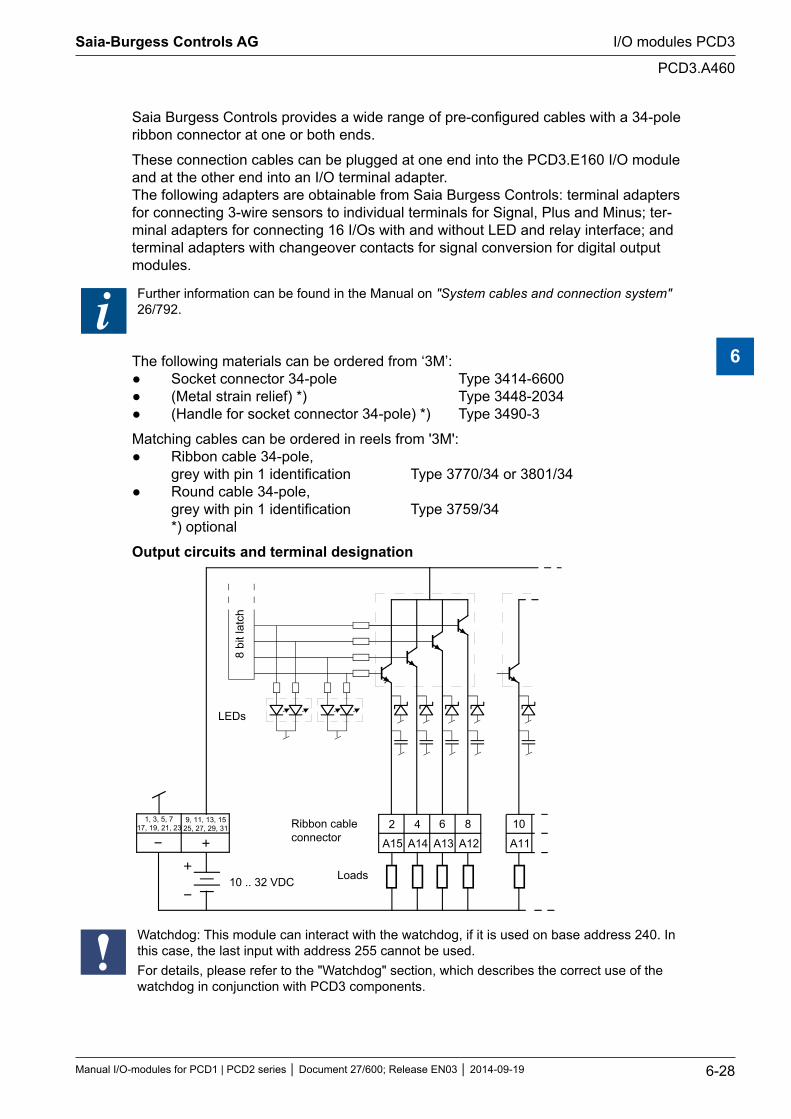
Saia Burgess Controls provides a wide range of pre-configured cables with a 34-pole ribbon connector at one or both ends.
These connection cables can be plugged at one end into the PCD3.E160 I/O module and at the other end into an I/O terminal adapter. The following adapters are obtainable from Saia Burgess Controls: terminal adapters for connecting 3-wire sensors to individual terminals for Signal, Plus and Minus; ter-minal adapters for connecting 16 I/Os with and without LED and relay interface; and terminal adapters with changeover contacts for signal conversion for digital output modules.
Further information can be found in the Manual on "System cables and connection system" 26/792.
The following materials can be ordered from ‘3M’: Socket connector 34-pole Type 3414-6600 (Metal strain relief) *) Type 3448-2034 (Handle for socket connector 34-pole) *) Type 3490-3
Matching cables can be ordered in reels from '3M': Ribbon cable 34-pole, grey with pin 1 identification Type 3770/34 or 3801/34 Round cable 34-pole, grey with pin 1 identification Type 3759/34 *) optional
Output circuits and terminal designation
1, 3, 5, 717, 19, 21, 23
9, 11, 13, 1525, 27, 29, 31
A15 A14
2 4
10 .. 32 VDC
Ribbon cableconnector
6 8
A13 A12
10
A11
8 bi
t lat
ch
LEDs
Loads
Watchdog: This module can interact with the watchdog, if it is used on base address 240. In this case, the last input with address 255 cannot be used.For details, please refer to the "Watchdog" section, which describes the correct use of the watchdog in conjunction with PCD3 components.
Saia-Burgess Controls AG
Manual I/O-modules for PCD1 | PCD2 series Document 27/600; Release EN03 2014-09-19 6-28
I/O modules PCD3
PCD3.A460
6
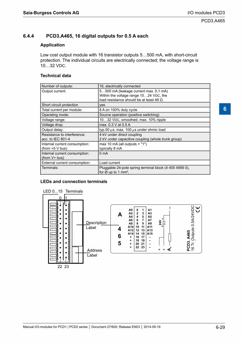
6.4.4 PCD3.A465, 16 digital outputs for 0.5 A each
Application
Low cost output module with 16 transistor outputs 5…500 mA, with short-circuit protection. The individual circuits are electrically connected; the voltage range is 10…32 VDC.
Technical data
Number of outputs: 16, electrically connectedOutput current: 5…500 mA (leakage current max. 0,1 mA)
Within the voltage range 10…24 VDC, the load resistance should be at least 48 Ω.
Short circuit protection yesTotal current per module: 8 A on 100% duty cycleOperating mode: Source operation (positive switching)Voltage range: 10…32 VDC, smoothed, max. 10% rippleVoltage drop: max. 0.3 V at 0.5 AOutput delay: typ.50 µs, max. 100 µs under ohmic loadResistance to interference: acc. to IEC 801-4
4 kV under direct coupling 2 kV under capacitive coupling (whole trunk group)
Internal current consumption: (from +5 V bus)
max 10 mA (all outputs = "1") typically 8 mA
Internal current consumption: (from V+ bus)
0 mA
External current consumption: Load currentTerminals: Pluggable 24-pole spring terminal block (4 405 4956 0),
for Ø up to 1 mm²,
LEDs and connection terminals
LED 0...15 Terminals
DescriptionLabel
AddressLabel
PCD
3.A
465
16Tr
. Out
puts
0.5
A24
VD
C/
1357911131517192123
02468
10121416182022
A0A2A4A6A8
A10A12A14
++++
A1A3A5A7A9A11A13A15
––––
–
+ + An
24V
+
–
0 1
22 23
A
465
Saia-Burgess Controls AG
Manual I/O-modules for PCD1 | PCD2 series Document 27/600; Release EN03 2014-09-19 6-29
I/O modules PCD3
PCD3.A465
6
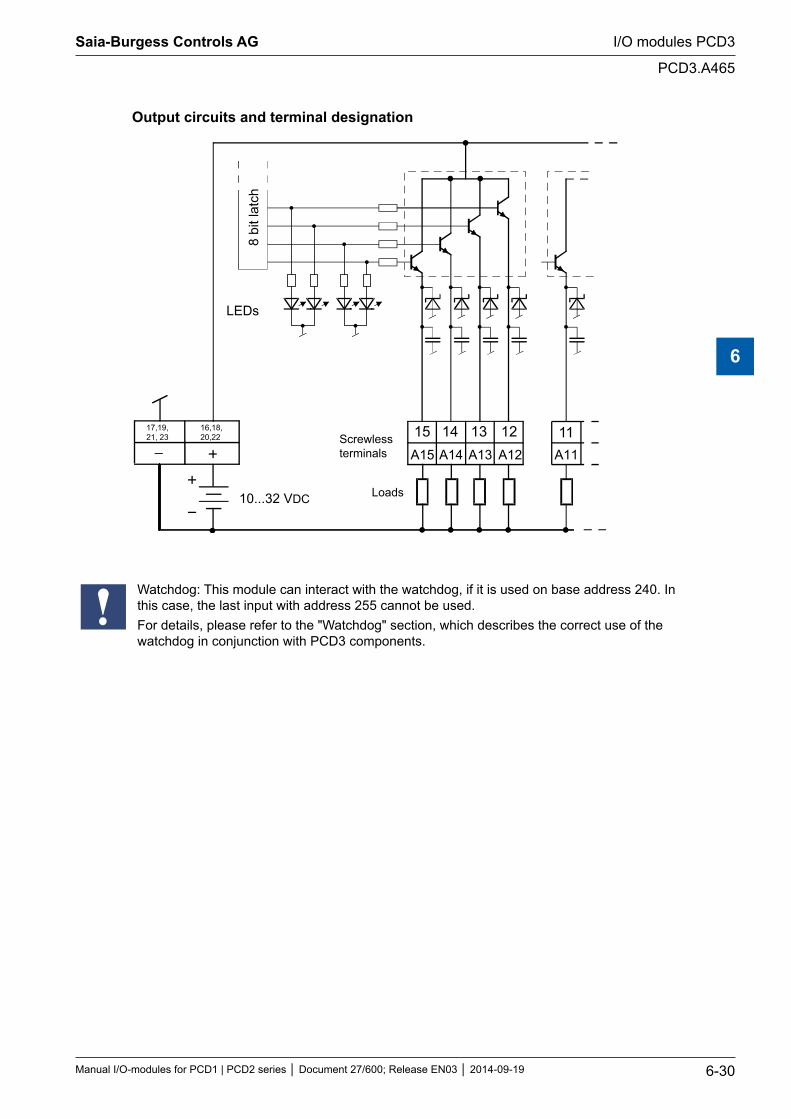
Output circuits and terminal designation
A15 A14 A13 A12 A11
17,19,21, 23
16,18, 20,22 15 14 13 12 11
8 bi
t lat
ch
Screwless terminals
Loads 10...32 VDC
LEDs
Watchdog: This module can interact with the watchdog, if it is used on base address 240. In this case, the last input with address 255 cannot be used.For details, please refer to the "Watchdog" section, which describes the correct use of the watchdog in conjunction with PCD3 components.
Saia-Burgess Controls AG
Manual I/O-modules for PCD1 | PCD2 series Document 27/600; Release EN03 2014-09-19 6-30
I/O modules PCD3
PCD3.A465
6
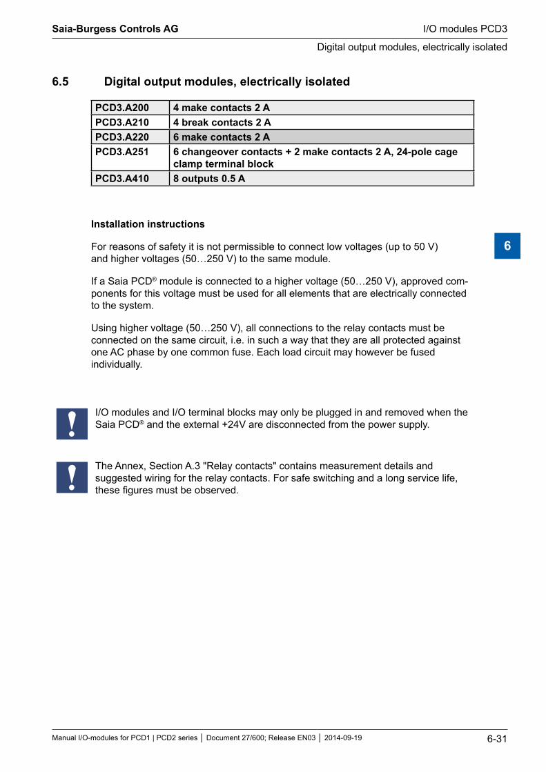
6.5 Digital output modules, electrically isolated
PCD3.A200 4 make contacts 2 A PCD3.A210 4 break contacts 2 A PCD3.A220 6 make contacts 2 APCD3.A251 6 changeover contacts + 2 make contacts 2 A, 24-pole cage
clamp terminal blockPCD3.A410 8 outputs 0.5 A
Installation instructions
For reasons of safety it is not permissible to connect low voltages (up to 50 V) and higher voltages (50…250 V) to the same module.
If a Saia PCD® module is connected to a higher voltage (50…250 V), approved com-ponents for this voltage must be used for all elements that are electrically connected to the system.
Using higher voltage (50…250 V), all connections to the relay contacts must be connected on the same circuit, i.e. in such a way that they are all protected against one AC phase by one common fuse. Each load circuit may however be fused individually.
I/O modules and I/O terminal blocks may only be plugged in and removed when the Saia PCD® and the external +24V are disconnected from the power supply.
The Annex, Section A.3 "Relay contacts" contains measurement details and suggested wiring for the relay contacts. For safe switching and a long service life, these figures must be observed.
Saia-Burgess Controls AG
Manual I/O-modules for PCD1 | PCD2 series Document 27/600; Release EN03 2014-09-19 6-31
I/O modules PCD3
Digital output modules, electrically isolated
6

6.5.1 PCD3.A200, 4 relays with make contacts, with contact protection
Application
The module contains 4 relays with normally-open contacts for direct or alternating current up to 2 A, 250 VAC. The contacts are protected by a varistor and an RC element. The module is especially suited wherever perfectly isolated AC switching circuits with infrequent switching have to be controlled.
Technical data
Number of outputs: 4, electrically isolated make contacts
Type of relay (typical): RE 03 0024, SCHRACK
Switching capacity: (contact lifetime)
2A, 250 VAC AC1 0.7 x 10⁶ operations 1 A, 250 VAC AC11 1.0 x 10⁶ operations 2 A, 50 VDC DC11 0.3 x 10⁶ operations 3) 1 A, 24 VDC DC11 0.1 x 10⁶ operations 1)3)
Relay coil supply: 2) nominal 24 VDC smoothed or pulsed, 8 mA per relay coil
Voltage tolerance, dependent on ambi-ent temperature:
20°C: 17.0…35 VDC 30°C: 19.5…35 VDC 40°C: 20.5…32 VDC 50°C: 21.5…30 VDC
Output delay: typically 5 ms at 24 VDC
Resistance to interference: acc. to IEC 801-4
4 kV under direct coupling 2 kV under capacitive coupling (whole trunk group)
Internal current consumption: (from +5 V bus)
1…15 mA typically 10 mA
Internal current consumption: (from V+ bus)
0 mA
External current consumption: max. 32 mA
Terminals: Plug-in 10-pole spring terminal block (4 405 4954 0) or pluggable 10-pole screw terminal block (4 405 4955 0), both for wires up to 2.5 mm²
1) With external protective diode 2) With reverse voltage protection 3) These ratings are not UL-listed
The Annex, Section A.3 "Relay contacts" contains measurement details and suggested wir-ing for the relay contacts. For safe switching and a long service life, these figures must be observed.
Saia-Burgess Controls AG
Manual I/O-modules for PCD1 | PCD2 series Document 27/600; Release EN03 2014-09-19 6-32
I/O modules PCD3
PCD3.A200
6
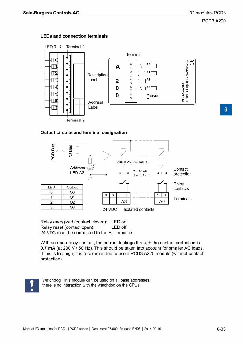
LEDs and connection terminals
01
2
3
4
56
7
LED 0...7 Terminal 0
DescriptionLabel
AddressLabel
PCD
3.A
200
4 R
el. O
utpu
ts 2
A/2
50VA
C
0123456789
A0
A1
A2
A3
+–
24VDC
––––
Terminal 9
Terminal
A
200
Output circuits and terminal designation
A00189
A367
I/O B
us
PC
D B
us
Contactprotection
Relaycontacts
Terminals
24 VDC Isolated contacts
Address-LED A3
VDR = 250VAC/400A
C = 10 nFR = 33 Ohm
LED Output0 O01 O12 O23 O3
Relay energized (contact closed): LED on Relay reset (contact open): LED off 24 VDC must be connected to the +/- terminals.
With an open relay contact, the current leakage through the contact protection is 0.7 mA (at 230 V / 50 Hz). This should be taken into account for smaller AC loads. If this is too high, it is recommended to use a PCD3.A220 module (without contact protection).
Watchdog: This module can be used on all base addresses; there is no interaction with the watchdog on the CPUs.
Saia-Burgess Controls AG
Manual I/O-modules for PCD1 | PCD2 series Document 27/600; Release EN03 2014-09-19 6-33
I/O modules PCD3
PCD3.A200
6
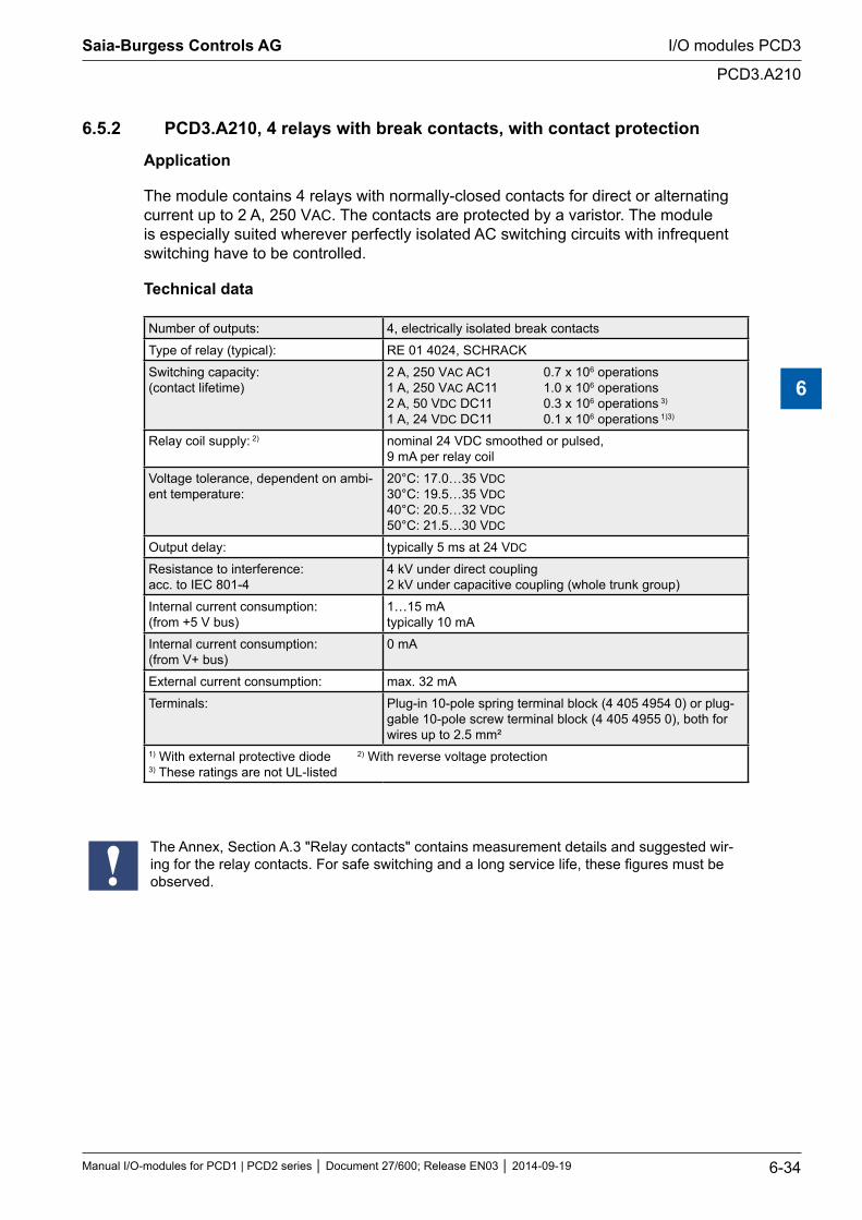
6.5.2 PCD3.A210, 4 relays with break contacts, with contact protection
Application
The module contains 4 relays with normally-closed contacts for direct or alternating current up to 2 A, 250 VAC. The contacts are protected by a varistor. The module is especially suited wherever perfectly isolated AC switching circuits with infrequent switching have to be controlled.
Technical data
Number of outputs: 4, electrically isolated break contacts
Type of relay (typical): RE 01 4024, SCHRACK
Switching capacity: (contact lifetime)
2 A, 250 VAC AC1 0.7 x 10⁶ operations 1 A, 250 VAC AC11 1.0 x 10⁶ operations 2 A, 50 VDC DC11 0.3 x 10⁶ operations 3) 1 A, 24 VDC DC11 0.1 x 10⁶ operations 1)3)
Relay coil supply: 2) nominal 24 VDC smoothed or pulsed, 9 mA per relay coil
Voltage tolerance, dependent on ambi-ent temperature:
20°C: 17.0…35 VDC 30°C: 19.5…35 VDC 40°C: 20.5…32 VDC 50°C: 21.5…30 VDC
Output delay: typically 5 ms at 24 VDC
Resistance to interference: acc. to IEC 801-4
4 kV under direct coupling 2 kV under capacitive coupling (whole trunk group)
Internal current consumption: (from +5 V bus)
1…15 mA typically 10 mA
Internal current consumption: (from V+ bus)
0 mA
External current consumption: max. 32 mA
Terminals: Plug-in 10-pole spring terminal block (4 405 4954 0) or plug-gable 10-pole screw terminal block (4 405 4955 0), both for wires up to 2.5 mm²
1) With external protective diode 2) With reverse voltage protection 3) These ratings are not UL-listed
The Annex, Section A.3 "Relay contacts" contains measurement details and suggested wir-ing for the relay contacts. For safe switching and a long service life, these figures must be observed.
Saia-Burgess Controls AG
Manual I/O-modules for PCD1 | PCD2 series Document 27/600; Release EN03 2014-09-19 6-34
I/O modules PCD3
PCD3.A210
6
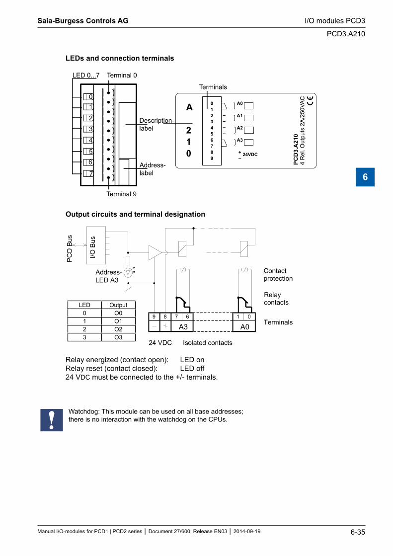
LEDs and connection terminals
01
2
3
4
56
7
LED 0...7 Terminal 0
PCD
3.A
210
4 R
el. O
utpu
ts 2
A/2
50VA
C
0123456789
A0
A1
A2
A3
+–
24VDC
––––
A
210
Terminal 9
Terminals
Description-label
Address-label
Output circuits and terminal designation
A00189
A367
I/O B
us
PC
D B
us
Contactprotection
Relaycontacts
Terminals
24 VDC Isolated contacts
Address-LED A3
LED Output0 O01 O12 O23 O3
Relay energized (contact open): LED on Relay reset (contact closed): LED off 24 VDC must be connected to the +/- terminals.
Watchdog: This module can be used on all base addresses; there is no interaction with the watchdog on the CPUs.
Saia-Burgess Controls AG
Manual I/O-modules for PCD1 | PCD2 series Document 27/600; Release EN03 2014-09-19 6-35
I/O modules PCD3
PCD3.A210
6
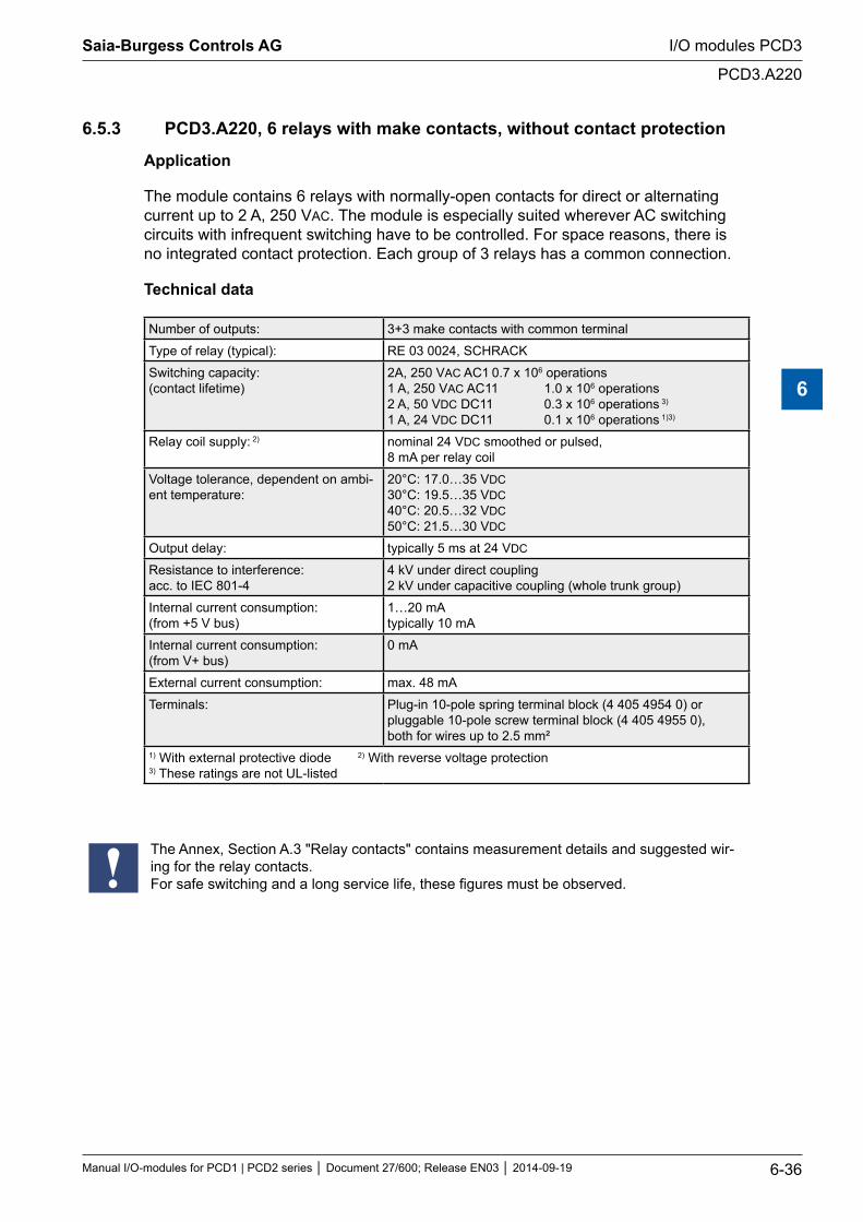
6.5.3 PCD3.A220, 6 relays with make contacts, without contact protection
Application
The module contains 6 relays with normally-open contacts for direct or alternating current up to 2 A, 250 VAC. The module is especially suited wherever AC switching circuits with infrequent switching have to be controlled. For space reasons, there is no integrated contact protection. Each group of 3 relays has a common connection.
Technical data
Number of outputs: 3+3 make contacts with common terminal
Type of relay (typical): RE 03 0024, SCHRACK
Switching capacity: (contact lifetime)
2A, 250 VAC AC1 0.7 x 10⁶ operations 1 A, 250 VAC AC11 1.0 x 10⁶ operations 2 A, 50 VDC DC11 0.3 x 10⁶ operations 3) 1 A, 24 VDC DC11 0.1 x 10⁶ operations 1)3)
Relay coil supply: 2) nominal 24 VDC smoothed or pulsed, 8 mA per relay coil
Voltage tolerance, dependent on ambi-ent temperature:
20°C: 17.0…35 VDC 30°C: 19.5…35 VDC 40°C: 20.5…32 VDC 50°C: 21.5…30 VDC
Output delay: typically 5 ms at 24 VDC
Resistance to interference: acc. to IEC 801-4
4 kV under direct coupling 2 kV under capacitive coupling (whole trunk group)
Internal current consumption: (from +5 V bus)
1…20 mA typically 10 mA
Internal current consumption: (from V+ bus)
0 mA
External current consumption: max. 48 mA
Terminals: Plug-in 10-pole spring terminal block (4 405 4954 0) or pluggable 10-pole screw terminal block (4 405 4955 0), both for wires up to 2.5 mm²
1) With external protective diode 2) With reverse voltage protection 3) These ratings are not UL-listed
The Annex, Section A.3 "Relay contacts" contains measurement details and suggested wir-ing for the relay contacts. For safe switching and a long service life, these figures must be observed.
Saia-Burgess Controls AG
Manual I/O-modules for PCD1 | PCD2 series Document 27/600; Release EN03 2014-09-19 6-36
I/O modules PCD3
PCD3.A220
6
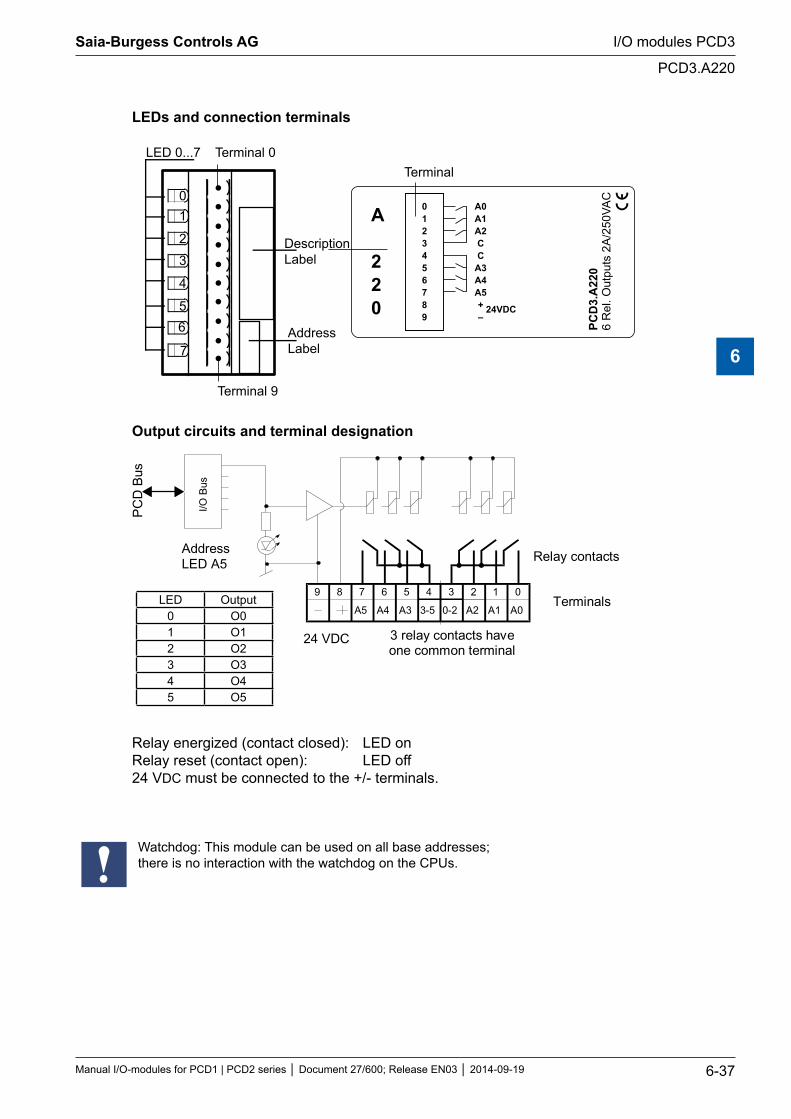
LEDs and connection terminals
01
2
3
4
56
7
LED 0...7 Terminal 0
DescriptionLabel
AddressLabel
PCD
3.A
220
6 R
el. O
utpu
ts 2
A/2
50VA
C
0123456789
A0A1A2CC
A3A4A5+–
24VDC
Terminal 9
Terminal
A
220
Output circuits and terminal designation
LED Output0 O01 O12 O23 O34 O45 O5
89
A4
67
I/O B
us
PC
D B
us
3-5
45
A1
23
A0
01
0-2 A2A3A5
Relay contacts
Terminals
24 VDC 3 relay contacts haveone common terminal
AddressLED A5
Relay energized (contact closed): LED on Relay reset (contact open): LED off 24 VDC must be connected to the +/- terminals.
Watchdog: This module can be used on all base addresses; there is no interaction with the watchdog on the CPUs.
Saia-Burgess Controls AG
Manual I/O-modules for PCD1 | PCD2 series Document 27/600; Release EN03 2014-09-19 6-37
I/O modules PCD3
PCD3.A220
6
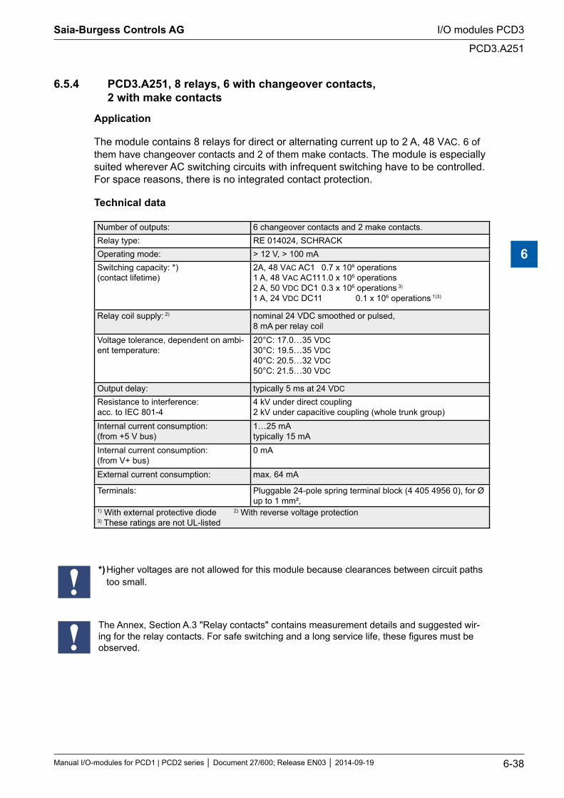
6.5.4 PCD3.A251, 8 relays, 6 with changeover contacts, 2 with make contacts
Application
The module contains 8 relays for direct or alternating current up to 2 A, 48 VAC. 6 of them have changeover contacts and 2 of them make contacts. The module is especially suited wherever AC switching circuits with infrequent switching have to be controlled. For space reasons, there is no integrated contact protection.
Technical data
Number of outputs: 6 changeover contacts and 2 make contacts.Relay type: RE 014024, SCHRACKOperating mode: > 12 V, > 100 mASwitching capacity: *) (contact lifetime)
2A, 48 VAC AC1 0.7 x 10⁶ operations 1 A, 48 VAC AC11 1.0 x 10⁶ operations 2 A, 50 VDC DC1 0.3 x 10⁶ operations 3) 1 A, 24 VDC DC11 0.1 x 10⁶ operations 1)3)
Relay coil supply: 2) nominal 24 VDC smoothed or pulsed, 8 mA per relay coil
Voltage tolerance, dependent on ambi-ent temperature:
20°C: 17.0…35 VDC 30°C: 19.5…35 VDC 40°C: 20.5…32 VDC 50°C: 21.5…30 VDC
Output delay: typically 5 ms at 24 VDC
Resistance to interference: acc. to IEC 801-4
4 kV under direct coupling 2 kV under capacitive coupling (whole trunk group)
Internal current consumption: (from +5 V bus)
1…25 mA typically 15 mA
Internal current consumption: (from V+ bus)
0 mA
External current consumption: max. 64 mA
Terminals: Pluggable 24-pole spring terminal block (4 405 4956 0), for Ø up to 1 mm²,
1) With external protective diode 2) With reverse voltage protection 3) These ratings are not UL-listed
*) Higher voltages are not allowed for this module because clearances between circuit paths too small.
The Annex, Section A.3 "Relay contacts" contains measurement details and suggested wir-ing for the relay contacts. For safe switching and a long service life, these figures must be observed.
Saia-Burgess Controls AG
Manual I/O-modules for PCD1 | PCD2 series Document 27/600; Release EN03 2014-09-19 6-38
I/O modules PCD3
PCD3.A251
6
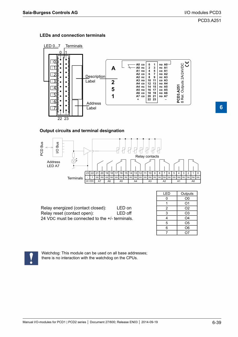
LEDs and connection terminals
LED 0...7 Terminals
DescriptionLabel
AddressLabel
PCD
3.A
251
8 R
el. O
utpu
ts 2
A/2
4VD
C
1357911131517192123
02468
10121416182022
A0A0A1A2A2A3A4A4A5A6A7+
concnoconcnoconcnococo
nonccononccononcconono
A0A1A1A2A3A3A4A5A5A6A7–
0 1
22 23
01234567
A
251
Output circuits and terminal designation
I/O B
us
PC
D B
us
AddressLED A7
23 22 21 20 19 18 17 16 15 14 13 12 11 10 9 8 7 6 5 4 3 2 1 0
- + co no co no co no nc nc no co co no nc nc no co co no nc nc no co
24 VDC A7 A6 A5 A4 A3 A2 A1 A0Terminals
Relay contacts
Relay energized (contact closed): LED on Relay reset (contact open): LED off 24 VDC must be connected to the +/- terminals.
LED Outputs0 O01 O12 O23 O34 O45 O56 O67 O7
Watchdog: This module can be used on all base addresses; there is no interaction with the watchdog on the CPUs.
Saia-Burgess Controls AG
Manual I/O-modules for PCD1 | PCD2 series Document 27/600; Release EN03 2014-09-19 6-39
I/O modules PCD3
PCD3.A251
6
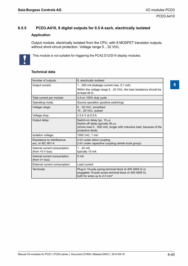
6.5.5 PCD3.A410, 8 digital outputs for 0.5 A each, electrically isolated
Application
Output module, electrically isolated from the CPU, with 8 MOSFET transistor outputs, without short-circuit protection. Voltage range 5…32 VDC.
This module is not suitable for triggering the PCA2.D12/D14 display modules.
Technical data
Number of outputs: 8, electrically isolated
Output current: 1…500 mA (leakage current max. 0,1 mA) Within the voltage range 5…24 VDC, the load resistance should be at least 48 Ω.
Total current per module: 4 A on 100% duty cycle
Operating mode: Source operation (positive switching)
Voltage range: 5…32 VDC, smoothed 10…25 VDC, pulsed
Voltage drop: ≤ 0.4 V at 0.5 A
Output delay: Switch-on delay typ. 10 µs Switch-off delay typically 50 µs (ohmic load 5…500 mA), longer with inductive load, because of the protective diode.
Isolation voltage: 1000 VAC, 1 min
Resistance to interference: acc. to IEC 801-4
4 kV under direct coupling 2 kV under capacitive coupling (whole trunk group)
Internal current consumption: (from +5 V bus)
1…24 mA typically 15 mA
Internal current consumption: (from V+ bus)
0 mA
External current consumption: Load current
Terminals: Plug-in 10-pole spring terminal block (4 405 4954 0) or pluggable 10-pole screw terminal block (4 405 4955 0), both for wires up to 2.5 mm²
Saia-Burgess Controls AG
Manual I/O-modules for PCD1 | PCD2 series Document 27/600; Release EN03 2014-09-19 6-40
I/O modules PCD3
PCD3.A410
6
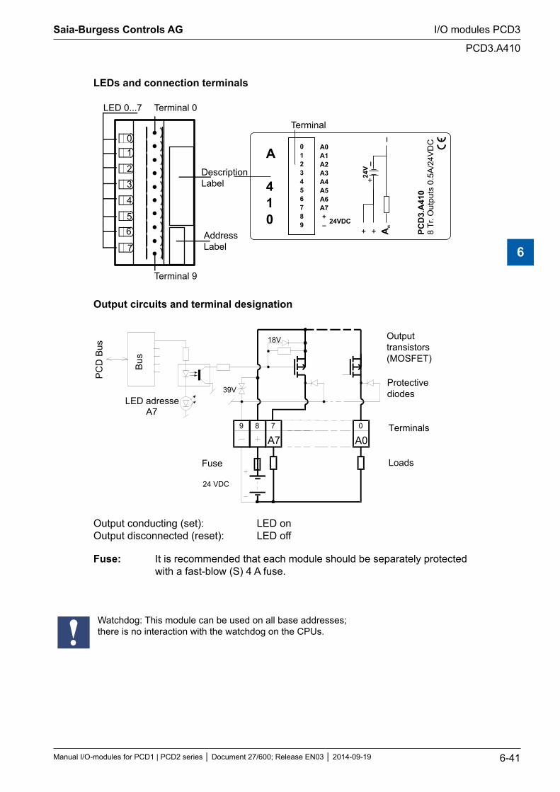
LEDs and connection terminals
01
2
3
4
56
7
LED 0...7 Terminal 0
DescriptionLabel
AddressLabel
24VDC
PCD
3.A
410
8Tr
. Out
puts
0.5
A/2
4VD
CA0A1A2A3A4A5A6A7+–
–
+ + An
24V
+
–
0123456789
Terminal 9
Terminal
A
410
Output circuits and terminal designation
A0089 7
Bus
PC
D B
us
24 VDC
Fuse
A7
18V
39VLED adresse
A7
Outputtransistors(MOSFET)
Protectivediodes
Terminals
Loads
Output conducting (set): LED on Output disconnected (reset): LED off
Fuse: It is recommended that each module should be separately protected with a fast-blow (S) 4 A fuse.
Watchdog: This module can be used on all base addresses; there is no interaction with the watchdog on the CPUs.
Saia-Burgess Controls AG
Manual I/O-modules for PCD1 | PCD2 series Document 27/600; Release EN03 2014-09-19 6-41
I/O modules PCD3
PCD3.A410
6
6.6 Digital output modules for manual operation, electrically isolated
PCD3.A810 Manual control module, with 2 changeover and 2 make con-tacts
PCD3.A860 Light and shade module, with 2 make contacts
The Annex, Section A.3 "Relay contacts" contains measurement details and suggested wir-ing for the relay contacts. For safe switching and a long service life, these figures must be observed.
Saia-Burgess Controls AG
Manual I/O-modules for PCD1 | PCD2 series Document 27/600; Release EN03 2014-09-19 6-42
I/O modules PCD3
Digital output modules for manual operation, electrically isolated
6
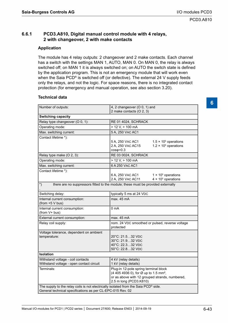
6.6.1 PCD3.A810, Digital manual control module with 4 relays, 2 with changeover, 2 with make contacts
Application
The module has 4 relay outputs: 2 changeover and 2 make contacts. Each channel has a switch with the settings MAN 1, AUTO, MAN 0. On MAN 0, the relay is always switched off; on MAN 1 it is always switched on; on AUTO the switch state is defined by the application program. This is not an emergency module that will work even when the Saia PCD® is switched off (or defective). The external 24 V supply feeds only the relays, and not the logic. For space reasons, there is no integrated contact protection (for emergency and manual operation, see also section 3.20).
Technical data
Number of outputs: 4, 2 changeover (O 0, 1) and 2 make contacts (O 2, 3)
Switching capacityRelay type changeover (O 0, 1): RE 01 4024, SCHRACKOperating mode: > 12 V, > 100 mAMax. switching current: 5 A, 250 VAC AC1Contact lifetime *):
5 A, 250 VAC AC1 1.5 × 10⁵ operations 2 A, 250 VAC AC15 1.2 × 10⁵ operations cosφ=0.3
Relay type make (O 2, 3): RE 03 0024, SCHRACKOperating mode: > 12 V, > 100 mAMax. switching current: 6 A 250 VAC AC1Contact lifetime *):
6 A, 250 VAC AC1 1 × 10⁵ operations 2 A, 250 VAC AC11 4 × 10⁵ operations
*) there are no suppressors fitted to the module; these must be provided externally .Switching delay: typically 5 ms at 24 VDC
Internal current consumption: (from +5 V bus)
max. 45 mA
Internal current consumption: (from V+ bus)
0 mA
External current consumption: max. 45 mA Relay coil supply: nom. 24 VDC smoothed or pulsed, reverse voltage
protectedVoltage tolerance, dependent on ambient temperature:
20°C: 21.5…32 VDC 30°C: 21.9…32 VDC 40°C: 22.3…32 VDC 50°C: 22.8…32 VDC
IsolationWithstand voltage - coil contacts Withstand voltage - open contact circuit
4 kV (relay details) 1 kV (relay details)
Terminals: Plug-in 12-pole spring terminal block (4 405 4936 0), for Ø up to 1.5 mm², or as above with 12 grouped strands, numbered, 2.5 m long (PCD3.K810)
The supply to the relay coils is not electrically isolated from the Saia PCD® side. General technical specifications as per CL-EPC-015 Rev. 02
Saia-Burgess Controls AG
Manual I/O-modules for PCD1 | PCD2 series Document 27/600; Release EN03 2014-09-19 6-43
I/O modules PCD3
PCD3.A810
6
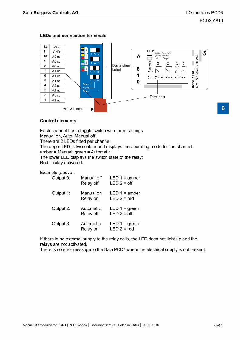
LEDs and connection terminals
1 A 0
1 A 0
1 A 0
1 A 0
12 24V 11 GND 10 A0 nc 9 A0 co 8 A0 no 7 A1 nc 6 A1 co 5 A1 no 4 A2 co 3 A2 no 2 A3 co 1 A3 no
Pin 12 in front
PCD
3.A
810
4 re
l. ou
t 5/6
A25
0 VA
C
A
810
12 11 10 9 8 7 6 5 4 3
A0
A1
A2
A3
+ –24
VD
C
2 1
LEDsgreen: Automaticyellow: Manual red: Output
Description-Label
Terminals
0
1
2
3
ManAutoMan
Control elements
Each channel has a toggle switch with three settings Manual on, Auto, Manual off. There are 2 LEDs fitted per channel: The upper LED is two-colour and displays the operating mode for the channel: amber = Manual; green = Automatic The lower LED displays the switch state of the relay: Red = relay activated.
Example (above): Output 0: Manual off LED 1 = amber Relay off LED 2 = off
Output 1: Manual on LED 1 = amber Relay on LED 2 = red
Output 2: Automatic LED 1 = green Relay off LED 2 = off
Output 3: Automatic LED 1 = green Relay on LED 2 = red
If there is no external supply to the relay coils, the LED does not light up and the relays are not activated. There is no error message to the Saia PCD® where the electrical supply is not present.
Saia-Burgess Controls AG
Manual I/O-modules for PCD1 | PCD2 series Document 27/600; Release EN03 2014-09-19 6-44
I/O modules PCD3
PCD3.A810
6
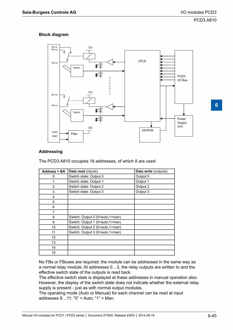
Block diagram
A0 nc A0 no
A0 co
A3 no
A3 co
+Uext
GND
PCD3 I/O Bus
CPLD
Filter EEPROM
Switch
Switch
Power Supply 3V3 UR
UR
UR
Addressing
The PCD3.A810 occupies 16 addresses, of which 8 are used:
Address + BA Data read (inputs) Data write (outputs)0 Switch state: Output 0 Output 01 Switch state: Output 1 Output 12 Switch state: Output 2 Output 23 Switch state: Output 3 Output 345678 Switch: Output 0 (0=auto;1=man)9 Switch: Output 1 (0=auto;1=man)
10 Switch: Output 2 (0=auto;1=man)11 Switch: Output 3 (0=auto;1=man)12131415
No FBs or FBoxes are required; the module can be addressed in the same way as a normal relay module. At addresses 0…3, the relay outputs are written to and the effective switch state of the outputs is read back. The effective switch state is displayed at these addresses in manual operation also. However, the display of the switch state does not indicate whether the external relay supply is present - just as with normal output modules. The operating mode (Auto or Manual) for each channel can be read at input addresses 8…11; "0” = Auto; “1” = Man.
Saia-Burgess Controls AG
Manual I/O-modules for PCD1 | PCD2 series Document 27/600; Release EN03 2014-09-19 6-45
I/O modules PCD3
PCD3.A810
6
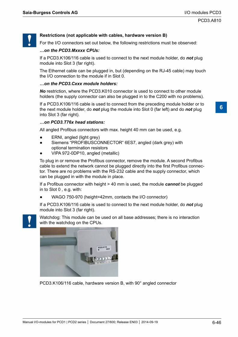
Restrictions (not applicable with cables, hardware version B)For the I/O connectors set out below, the following restrictions must be observed:
…on the PCD3.Mxxxx CPUs:If a PCD3.K106/116 cable is used to connect to the next module holder, do not plug module into Slot 3 (far right).
The Ethernet cable can be plugged in, but (depending on the RJ-45 cable) may touch the I/O connection to the module if in Slot 0.
…on the PCD3.Cxxx module holders:No restriction, where the PCD3.K010 connector is used to connect to other module holders (the supply connector can also be plugged in to the C200 with no problems).
If a PCD3.K106/116 cable is used to connect from the preceding module holder or to the next module holder, do not plug the module into Slot 0 (far left) and do not plug into Slot 3 (far right).
…on PCD3.T76x head stations:All angled Profibus connectors with max. height 40 mm can be used, e.g.
ERNI, angled (light grey) Siemens “PROFIBUSCONNECTOR“ 6ES7, angled (dark grey) with optional termination resistors VIPA 972-0DP10, angled (metallic)
To plug in or remove the Profibus connector, remove the module. A second Profibus cable to extend the network cannot be plugged directly into the first Profibus connec-tor. There are no problems with the RS-232 cable and the supply connector, which can be plugged in with the module in place.
If a Profibus connector with height > 40 mm is used, the module cannot be plugged in to Slot 0 , e.g. with:
WAGO 750-970 (height=42mm, contacts the I/O connector)
If a PCD3.K106/116 cable is used to connect to the next module holder, do not plug module into Slot 3 (far right).
Watchdog: This module can be used on all base addresses; there is no interaction with the watchdog on the CPUs.
PCD3.K106/116 cable, hardware version B, with 90° angled connector
Saia-Burgess Controls AG
Manual I/O-modules for PCD1 | PCD2 series Document 27/600; Release EN03 2014-09-19 6-46
I/O modules PCD3
PCD3.A810
6
6.6.2 PCD3.A860, digital light and shade module, with 2 make contacts
Application
The module is a light and shade module with a manual control option. The desired functionality can be selected in the user program. There are two efficient make contacts (without suppressors) and 2 digital inputs. It is also possible to operate this module in "transparent mode". In this mode, the module is a pure I/O module with two inputs/outputs.
Technical data
Digital inputs: 2
Digital outputs: 2
Contact type 2 make contact
Nominal voltage: 12 A / 250 VAC each
Peak start-up current (20 ms): 80 A (AC)
Reverse voltage protection (Uext): yes
Time constant of input filter: typically 6 ms
Internal current consumption: (from +5 V bus)
max. 40 mA (both input LEDs on)
Internal current consumption: (from V+ bus)
0 mA
External current consumption: max. 40 mA (both relay coils live, both output LEDs on)
Terminals, Relay outputs: Sensor inputs:
1 x pluggable 4-pole cage clamp terminal block (4 405 5027 0), for wires up to 2.5 mm², or as above with 4 grouped strands, numbered, 2.5 m long (PCD3.K860) 1 x pluggable 6-pole cage clamp terminal block (4 405 5028 0), for wires up to 1.0 mm², or as above with 6 grouped strands, numbered, 2.5 m long (PCD3.K861)
Saia-Burgess Controls AG
Manual I/O-modules for PCD1 | PCD2 series Document 27/600; Release EN03 2014-09-19 6-47
I/O modules PCD3
PCD3.A860
6
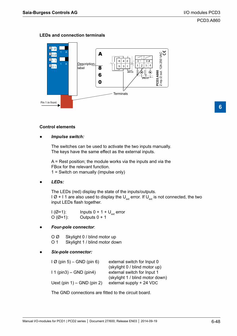
LEDs and connection terminals
1 A
1 A
I Ø
O Ø
O 1
I 1 6 4 2
5 3 1
PCD
3.A
860
2 in
p./2
out
. 12A
250
VA
CA
860
Description-label
Pin 1 in front
Terminals
Control elements
Impulseswitch:
The switches can be used to activate the two inputs manually. The keys have the same effect as the external inputs.
A = Rest position; the module works via the inputs and via the FBox for the relevant function. 1 = Switch on manually (impulse only)
LEDs:
The LEDs (red) display the state of the inputs/outputs. I Ø + I 1 are also used to display the Uext error. If Uext is not connected, the two input LEDs flash together.
I (Ø+1): Inputs 0 + 1 + Uext error O (Ø+1): Outputs 0 + 1
Four-pole connector:
O Ø Skylight 0 / blind motor up O 1 Skylight 1 / blind motor down
Six-pole connector:
I Ø (pin 5) – GND (pin 6) external switch for Input 0 (skylight 0 / blind motor up) I 1 (pin3) – GND (pin4) external switch for Input 1 (skylight 1 / blind motor down) Uext (pin 1) – GND (pin 2) external supply + 24 VDC
The GND connections are fitted to the circuit board.
Saia-Burgess Controls AG
Manual I/O-modules for PCD1 | PCD2 series Document 27/600; Release EN03 2014-09-19 6-48
I/O modules PCD3
PCD3.A860
6
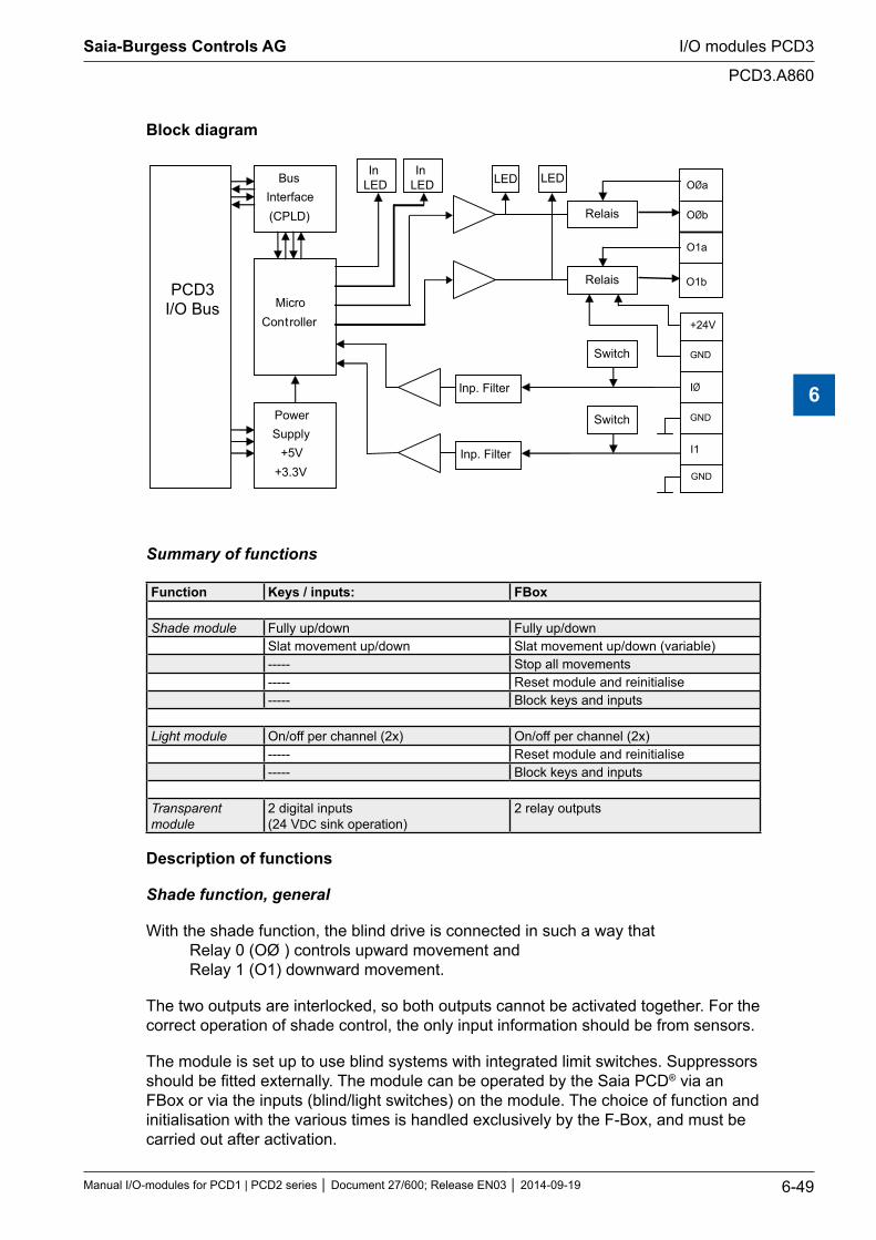
Block diagram
PCD3 I/O Bus
Bus Interface(CPLD)
Micro Controller
Switch
Relais
PowerSupply
+5V+3.3V
Relais
InLED
Switch
Inp. Filter
Inp. Filter
InLED
IØ
I1
GND
GND
+24V
OØa
OØb
O1b
O1a
GND
LEDLED
Summary of functions
Function Keys / inputs: FBox
Shade module Fully up/down Fully up/downSlat movement up/down Slat movement up/down (variable)----- Stop all movements----- Reset module and reinitialise----- Block keys and inputs
Light module On/off per channel (2x) On/off per channel (2x)----- Reset module and reinitialise----- Block keys and inputs
Transparent module
2 digital inputs (24 VDC sink operation)
2 relay outputs
Description of functions
Shade function, general
With the shade function, the blind drive is connected in such a way that Relay 0 (OØ ) controls upward movement and Relay 1 (O1) downward movement.
The two outputs are interlocked, so both outputs cannot be activated together. For the correct operation of shade control, the only input information should be from sensors.
The module is set up to use blind systems with integrated limit switches. Suppressors should be fitted externally. The module can be operated by the Saia PCD® via an FBox or via the inputs (blind/light switches) on the module. The choice of function and initialisation with the various times is handled exclusively by the F-Box, and must be carried out after activation.
Saia-Burgess Controls AG
Manual I/O-modules for PCD1 | PCD2 series Document 27/600; Release EN03 2014-09-19 6-49
I/O modules PCD3
PCD3.A860
6
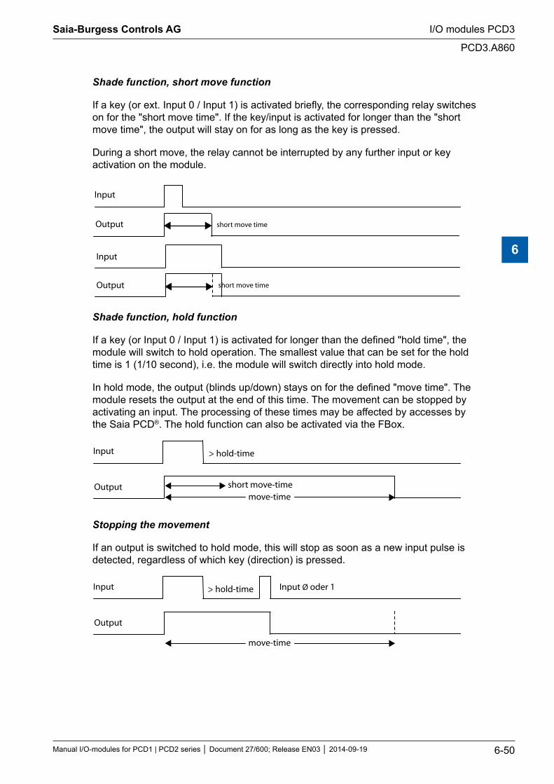
Shade function, short move function
If a key (or ext. Input 0 / Input 1) is activated briefly, the corresponding relay switches on for the "short move time". If the key/input is activated for longer than the "short move time", the output will stay on for as long as the key is pressed.
During a short move, the relay cannot be interrupted by any further input or key activation on the module.
Input
Output
Input
Output
short move time
short move time
Shade function, hold function
If a key (or Input 0 / Input 1) is activated for longer than the defined "hold time", the module will switch to hold operation. The smallest value that can be set for the hold time is 1 (1/10 second), i.e. the module will switch directly into hold mode.
In hold mode, the output (blinds up/down) stays on for the defined "move time". The module resets the output at the end of this time. The movement can be stopped by activating an input. The processing of these times may be affected by accesses by the Saia PCD®. The hold function can also be activated via the FBox.
Input
Output
> hold-time
move-time short move-time
Stopping the movement
If an output is switched to hold mode, this will stop as soon as a new input pulse is detected, regardless of which key (direction) is pressed.
Input
Output
> hold-time
move-time
Input Ø oder 1
Saia-Burgess Controls AG
Manual I/O-modules for PCD1 | PCD2 series Document 27/600; Release EN03 2014-09-19 6-50
I/O modules PCD3
PCD3.A860
6
Special case: If both keys are pressed together and held down, Relay 0 will switch on and the long ("hold") movement will be executed. When the time has expired, Relay 1 will switch on immediately, and a long movement in the reverse direction will occur.
Light function
With the light function, a skylight is connected to each of Outputs O Ø and O 1. Activating an input / key switches the relevant output on or off. Each pulse at the input switches the output over (toggling).
Where multiple keys are provided for a skylight, they can be wired in parallel to the same output.
Transparent function
In transparent mode, the inputs/outputs are not interlocked. The card is used like a digital I/O card, except that it is controlled via an FBox.
RIO operation
The switches/keys cannot be read via “Monitorio”.
Operation in an xx7 control
To use the module in an xx7 control requires FBs, which can be provided later on request. They do not have to be implemented in the "IO Builder".
Saia-Burgess Controls AG
Manual I/O-modules for PCD1 | PCD2 series Document 27/600; Release EN03 2014-09-19 6-51
I/O modules PCD3
PCD3.A860
6

Restrictions (not applicable with cables, hardware version B)For the I/O connectors set out below, the following restrictions must be observed:
…on the PCD3.Mxxxx CPUs:If a PCD3.K106/116 cable is used to connect to the next module holder, do not plug module into Slot 3 (far right).
The USB cable can be plugged in, but may touch the I/O connection to the module if in Slot 0.
…on the PCD3.Cxxx module holders:No restriction, where the PCD3.K010 connector is used to connect to other module holders (the supply connector can also be plugged in to the C200 with no problems).
If a PCD3.K106/116 cable is used to connect from the preceding module holder or to the next module holder, do not plug the module into Slot 0 (far left) and do not plug into Slot 3 (far right).
…on PCD3.T76x head stations:All angled Profibus connectors with max. height 40 mm can be used, e.g.
ERNI, angled (light grey) Siemens “PROFIBUSCONNECTOR“ 6ES7, angled (dark grey) with optional termination resistors VIPA 972-0DP10, angled (metallic)
To plug in or remove the Profibus connector, remove the module. A second Profibus cable to extend the network cannot be plugged directly into the first Profibus connec-tor. There are no problems with the RS-232 cable and the supply connector, which can be plugged in with the module in place.
If a Profibus connector with height > 40 mm is used, the module cannot be plugged in to Slot 0 , e.g. with:
WAGO 750-970 (height=42mm, contacts the I/O connector)
If a PCD3.K106/116 cable is used to connect to the next module holder, do not plug module into Slot 3 (far right).
Watchdog: This module can be used on all base addresses; there is no interaction with the watchdog on the CPUs.
PCD3.K106/116 cable, hardware version B, with 90° angled connector
Saia-Burgess Controls AG
Manual I/O-modules for PCD1 | PCD2 series Document 27/600; Release EN03 2014-09-19 6-52
I/O modules PCD3
PCD3.A860
6
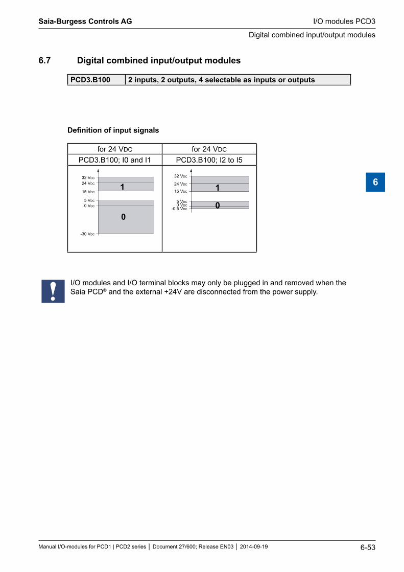
6.7 Digital combined input/output modules
PCD3.B100 2 inputs, 2 outputs, 4 selectable as inputs or outputs
Definition of input signals
for 24 VDC for 24 VDC
PCD3.B100; I0 and I1 PCD3.B100; I2 to I5
32 VDC
24 VDC
15 VDC
0 VDC
5 VDC
-30 VDC
1
0
32 VDC
24 VDC
15 VDC
0 VDC5 VDC
-0.5 VDC
1
0
I/O modules and I/O terminal blocks may only be plugged in and removed when the Saia PCD® and the external +24V are disconnected from the power supply.
Saia-Burgess Controls AG
Manual I/O-modules for PCD1 | PCD2 series Document 27/600; Release EN03 2014-09-19 6-53
I/O modules PCD3
Digital combined input/output modules
6
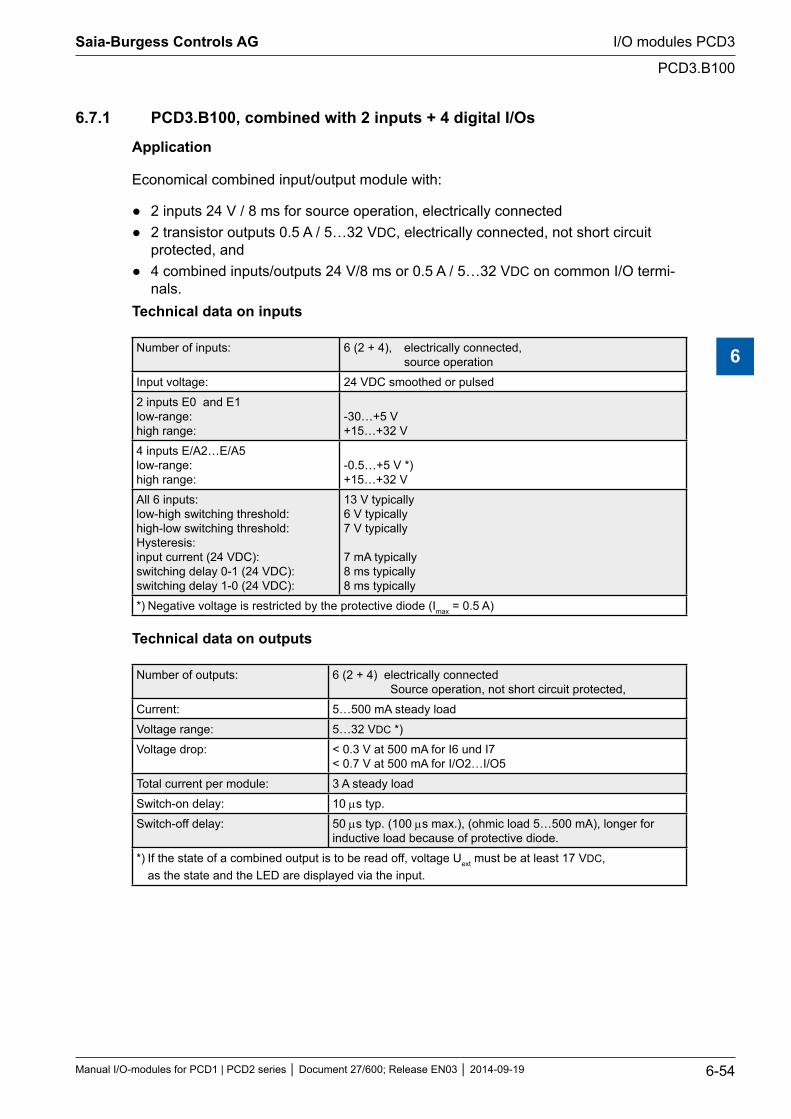
6.7.1 PCD3.B100, combined with 2 inputs + 4 digital I/Os
Application
Economical combined input/output module with:
2 inputs 24 V / 8 ms for source operation, electrically connected 2 transistor outputs 0.5 A / 5…32 VDC, electrically connected, not short circuit
protected, and 4 combined inputs/outputs 24 V/8 ms or 0.5 A / 5…32 VDC on common I/O termi-
nals.Technical data on inputs
Number of inputs: 6 (2 + 4), electrically connected, source operation
Input voltage: 24 VDC smoothed or pulsed
2 inputs E0 and E1 low-range: high range:
-30…+5 V +15…+32 V
4 inputs E/A2…E/A5 low-range: high range:
-0.5…+5 V *) +15…+32 V
All 6 inputs: low-high switching threshold: high-low switching threshold: Hysteresis: input current (24 VDC): switching delay 0-1 (24 VDC): switching delay 1-0 (24 VDC):
13 V typically 6 V typically 7 V typically 7 mA typically 8 ms typically 8 ms typically
*) Negative voltage is restricted by the protective diode (Imax = 0.5 A)
Technical data on outputs
Number of outputs: 6 (2 + 4) electrically connected Source operation, not short circuit protected,
Current: 5…500 mA steady load
Voltage range: 5…32 VDC *)
Voltage drop: < 0.3 V at 500 mA for I6 und I7 < 0.7 V at 500 mA for I/O2…I/O5
Total current per module: 3 A steady load
Switch-on delay: 10 µs typ.
Switch-off delay: 50 µs typ. (100 µs max.), (ohmic load 5…500 mA), longer for inductive load because of protective diode.
*) If the state of a combined output is to be read off, voltage Uext must be at least 17 VDC, as the state and the LED are displayed via the input.
Saia-Burgess Controls AG
Manual I/O-modules for PCD1 | PCD2 series Document 27/600; Release EN03 2014-09-19 6-54
I/O modules PCD3
PCD3.B100
6
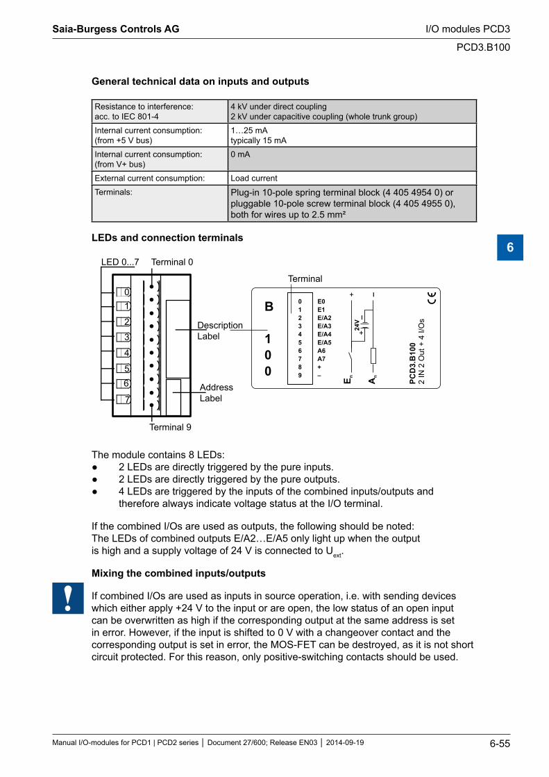
General technical data on inputs and outputs
Resistance to interference: acc. to IEC 801-4
4 kV under direct coupling 2 kV under capacitive coupling (whole trunk group)
Internal current consumption: (from +5 V bus)
1…25 mA typically 15 mA
Internal current consumption: (from V+ bus)
0 mA
External current consumption: Load current
Terminals: Plug-in 10-pole spring terminal block (4 405 4954 0) or pluggable 10-pole screw terminal block (4 405 4955 0), both for wires up to 2.5 mm²
LEDs and connection terminals
01
2
3
4
56
7
LED 0...7 Terminal 0
DescriptionLabel
AddressLabel
0123456789
E0E1E 2E 3EEA6A7+–
/A/A/A4/A5
PCD
3.B
100
2 IN
2 O
ut +
4 I/
Os
E n+ –
An
24V
+
–
Terminal 9
Terminal
B
100
The module contains 8 LEDs: 2 LEDs are directly triggered by the pure inputs. 2 LEDs are directly triggered by the pure outputs. 4 LEDs are triggered by the inputs of the combined inputs/outputs and therefore always indicate voltage status at the I/O terminal.
If the combined I/Os are used as outputs, the following should be noted: The LEDs of combined outputs E/A2…E/A5 only light up when the output is high and a supply voltage of 24 V is connected to Uext.
Mixing the combined inputs/outputs
If combined I/Os are used as inputs in source operation, i.e. with sending devices which either apply +24 V to the input or are open, the low status of an open input can be overwritten as high if the corresponding output at the same address is set in error. However, if the input is shifted to 0 V with a changeover contact and the corresponding output is set in error, the MOS-FET can be destroyed, as it is not short circuit protected. For this reason, only positive-switching contacts should be used.
Saia-Burgess Controls AG
Manual I/O-modules for PCD1 | PCD2 series Document 27/600; Release EN03 2014-09-19 6-55
I/O modules PCD3
PCD3.B100
6
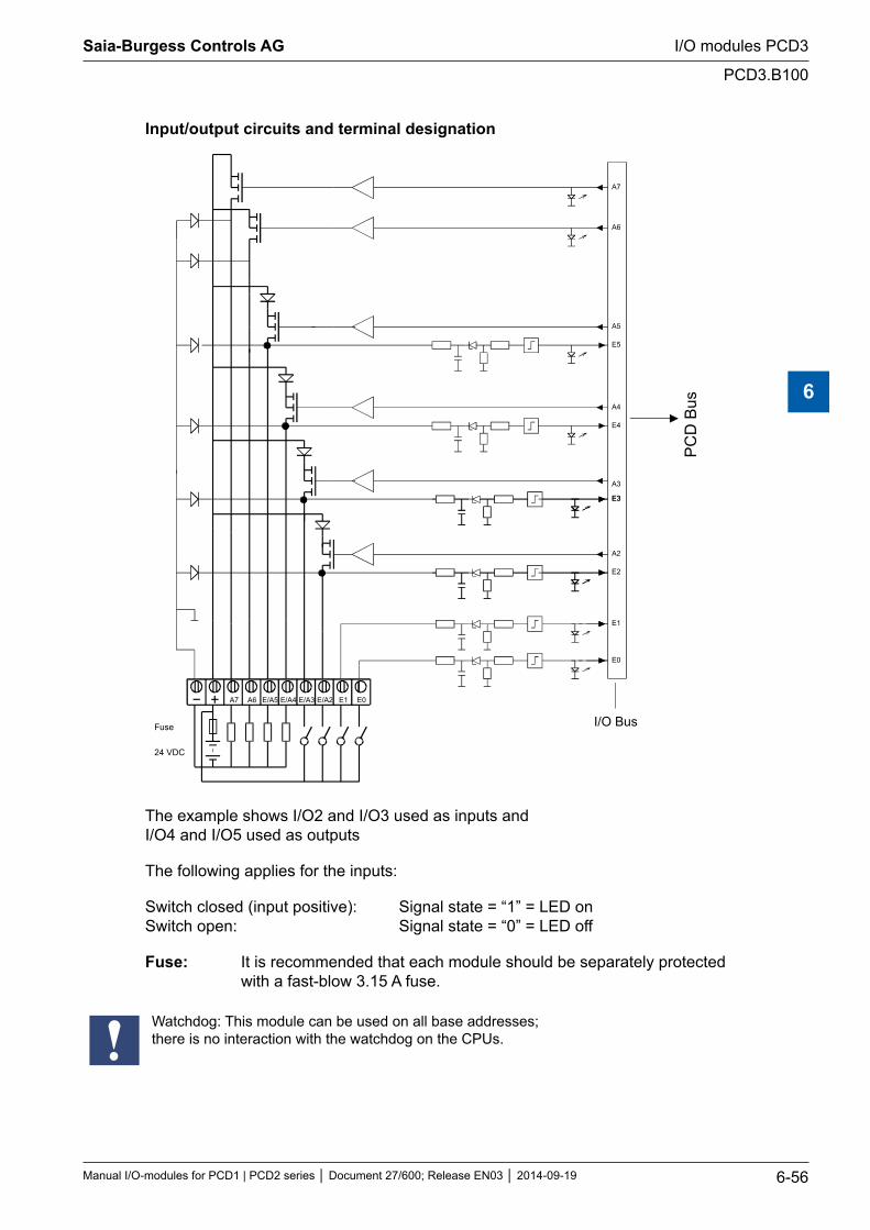
Input/output circuits and terminal designation
E/A5 E/A4 E/A3 E/A2 E1 E0A6A7
E1
E4
A4
A7
A6
E3
A3
A5
E0
E5
E3
A2
E2
I/O Bus
PC
D B
us
24 VDC
Fuse
The example shows I/O2 and I/O3 used as inputs and I/O4 and I/O5 used as outputs
The following applies for the inputs:
Switch closed (input positive): Signal state = “1” = LED on Switch open: Signal state = “0” = LED off
Fuse: It is recommended that each module should be separately protected with a fast-blow 3.15 A fuse.
Watchdog: This module can be used on all base addresses; there is no interaction with the watchdog on the CPUs.
Saia-Burgess Controls AG
Manual I/O-modules for PCD1 | PCD2 series Document 27/600; Release EN03 2014-09-19 6-56
I/O modules PCD3
PCD3.B100
6
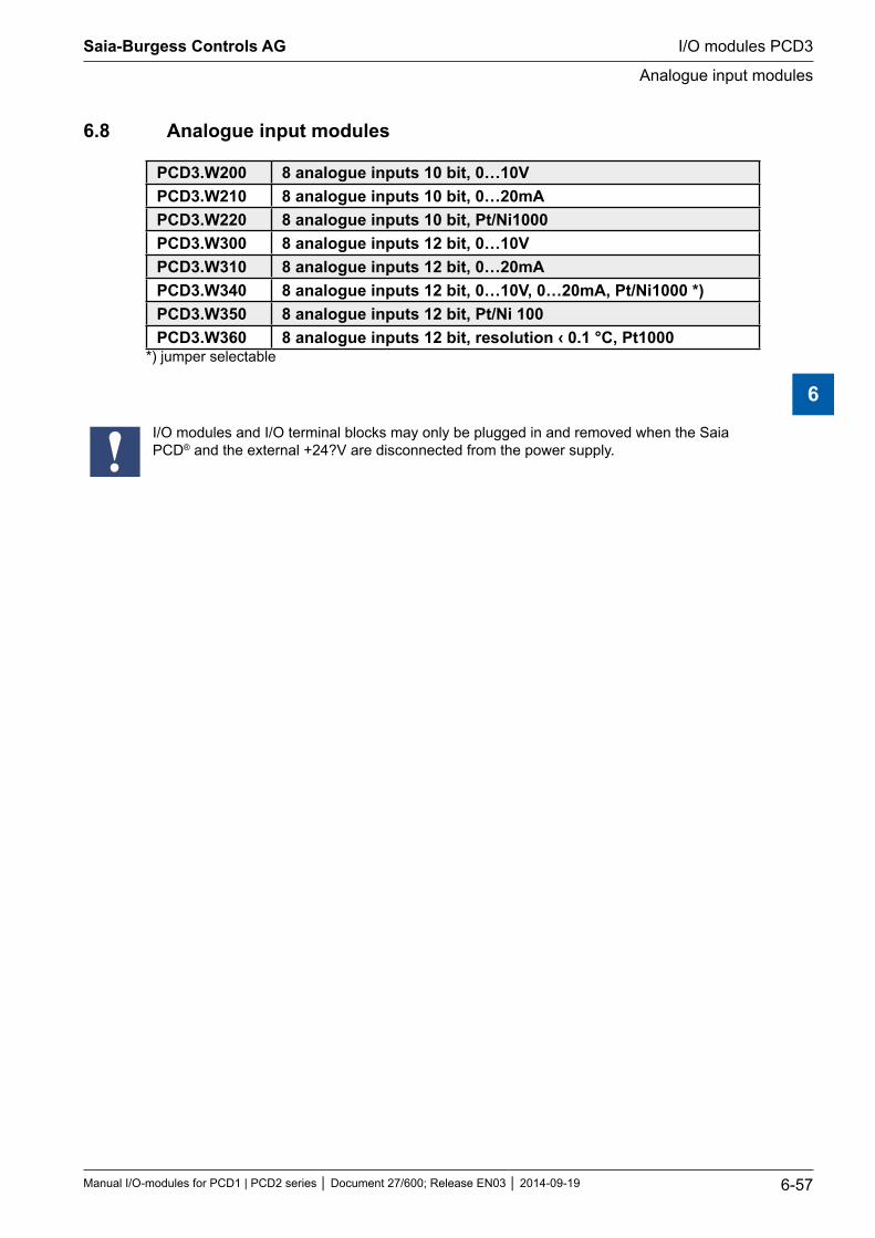
6.8 Analogue input modules
PCD3.W200 8 analogue inputs 10 bit, 0…10VPCD3.W210 8 analogue inputs 10 bit, 0…20mAPCD3.W220 8 analogue inputs 10 bit, Pt/Ni1000PCD3.W300 8 analogue inputs 12 bit, 0…10VPCD3.W310 8 analogue inputs 12 bit, 0…20mAPCD3.W340 8 analogue inputs 12 bit, 0…10V, 0…20mA, Pt/Ni1000 *)PCD3.W350 8 analogue inputs 12 bit, Pt/Ni 100PCD3.W360 8 analogue inputs 12 bit, resolution ‹ 0.1 °C, Pt1000
*) jumper selectable
I/O modules and I/O terminal blocks may only be plugged in and removed when the Saia PCD® and the external +24?V are disconnected from the power supply.
Saia-Burgess Controls AG
Manual I/O-modules for PCD1 | PCD2 series Document 27/600; Release EN03 2014-09-19 6-57
I/O modules PCD3
Analogue input modules
6
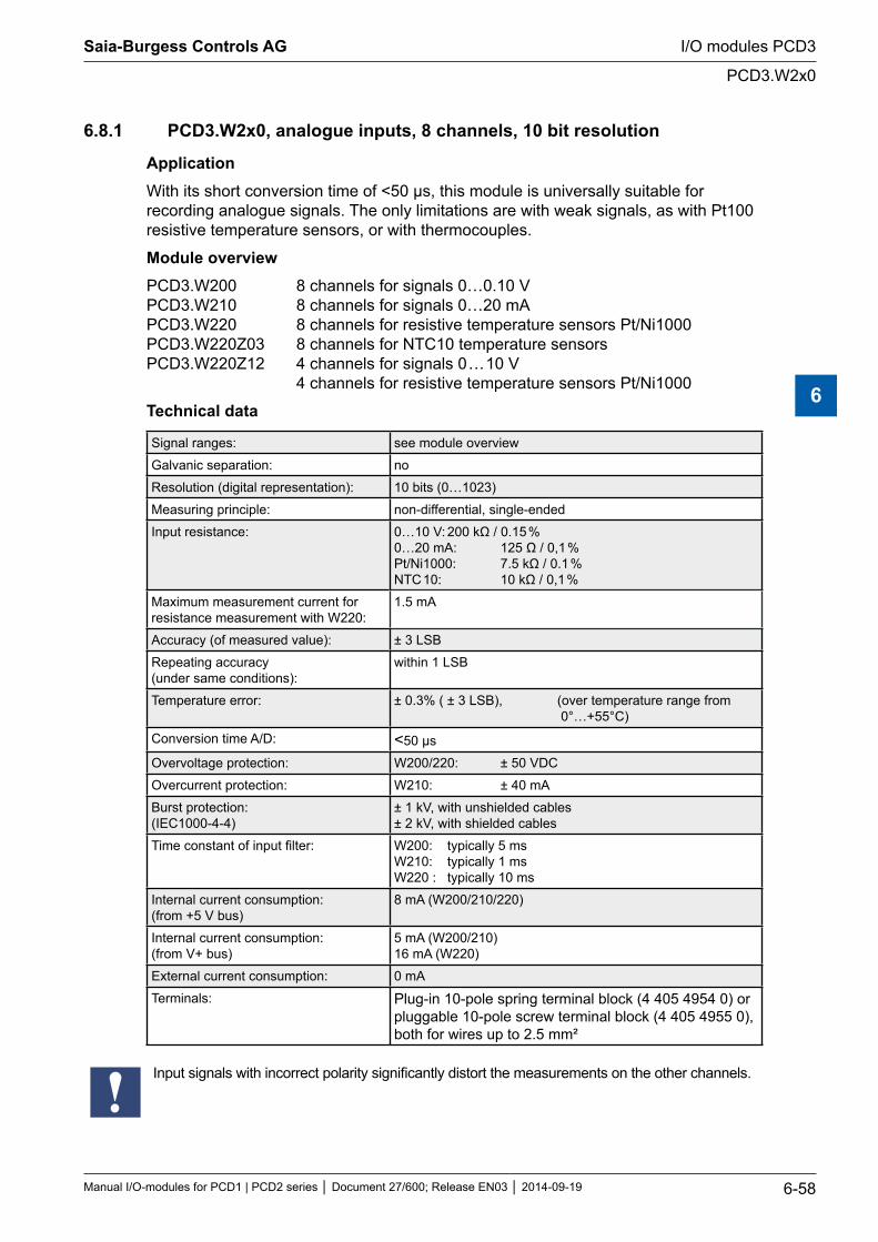
6.8.1 PCD3.W2x0, analogue inputs, 8 channels, 10 bit resolution
ApplicationWith its short conversion time of <50 µs, this module is universally suitable for recording analogue signals. The only limitations are with weak signals, as with Pt100 resistive temperature sensors, or with thermocouples.
Module overviewPCD3.W200 8 channels for signals 0…0.10 V PCD3.W210 8 channels for signals 0…20 mA PCD3.W220 8 channels for resistive temperature sensors Pt/Ni1000 PCD3.W220Z03 8 channels for NTC10 temperature sensors PCD3.W220Z12 4 channels for signals 0 … 10 V 4 channels for resistive temperature sensors Pt/Ni1000
Technical data
Signal ranges: see module overview
Galvanic separation: no
Resolution (digital representation): 10 bits (0…1023)
Measuring principle: non-differential, single-ended
Input resistance: 0…10 V: 200 kΩ / 0.15 % 0…20 mA: 125 Ω / 0,1 % Pt/Ni1000: 7.5 kΩ / 0.1 % NTC 10: 10 kΩ / 0,1 %
Maximum measurement current for resistance measurement with W220:
1.5 mA
Accuracy (of measured value): ± 3 LSB
Repeating accuracy (under same conditions):
within 1 LSB
Temperature error: ± 0.3% ( ± 3 LSB), (over temperature range from 0°…+55°C)
Conversion time A/D: <50 μs
Overvoltage protection: W200/220: ± 50 VDC
Overcurrent protection: W210: ± 40 mA
Burst protection: (IEC1000-4-4)
± 1 kV, with unshielded cables ± 2 kV, with shielded cables
Time constant of input filter: W200: typically 5 ms W210: typically 1 ms W220 : typically 10 ms
Internal current consumption: (from +5 V bus)
8 mA (W200/210/220)
Internal current consumption: (from V+ bus)
5 mA (W200/210) 16 mA (W220)
External current consumption: 0 mA
Terminals: Plug-in 10-pole spring terminal block (4 405 4954 0) or pluggable 10-pole screw terminal block (4 405 4955 0), both for wires up to 2.5 mm²
Input signals with incorrect polarity significantly distort the measurements on the other channels.
Saia-Burgess Controls AG
Manual I/O-modules for PCD1 | PCD2 series Document 27/600; Release EN03 2014-09-19 6-58
I/O modules PCD3
PCD3.W2x0
6
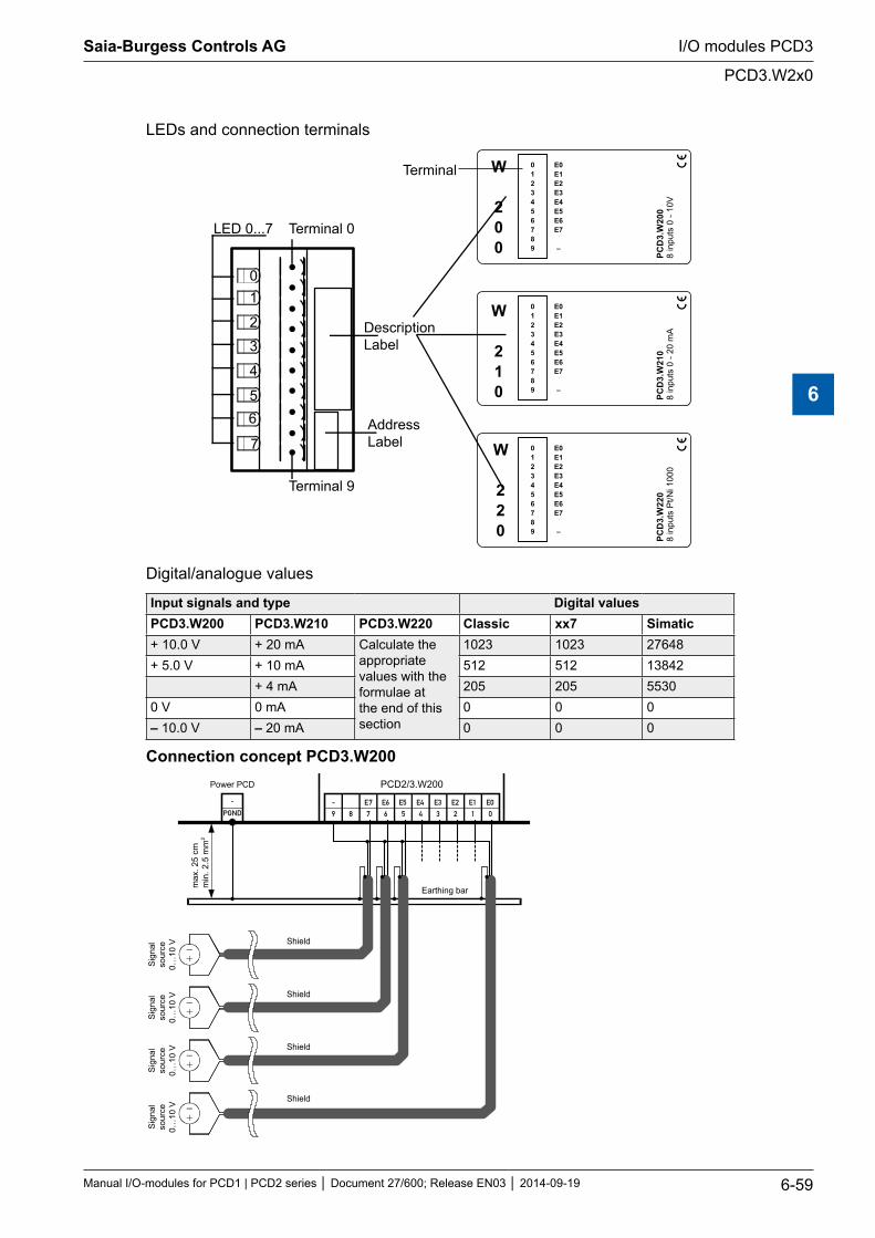
LEDs and connection terminals
01
2
3
4
56
7
LED 0...7 Terminal 0
DescriptionLabel
AddressLabel 0
123456789
0123456789
0123456789
E0E1E2E3E4E5E6E7
–
E0E1E2E3E4E5E6E7
–
E0E1E2E3E4E5E6E7
–
PCD
3.W
022
8 in
puts
Pt/N
i 100
0 PC
D3.
W0
218
inpu
ts 0
- 20
mA
PCD
3.W
0028
inpu
ts
1V
0 -
0
Terminal 9
Terminal W
200
W
210
W
220
Digital/analogue values
Input signals and type Digital values PCD3.W200 PCD3.W210 PCD3.W220 Classic xx7 Simatic+ 10.0 V + 20 mA Calculate the
appropriate values with the formulae at the end of this section
1023 1023 27648+ 5.0 V + 10 mA 512 512 13842
+ 4 mA 205 205 55300 V 0 mA 0 0 0– 10.0 V – 20 mA 0 0 0
Connection concept PCD3.W200
9 8 7 6 5 4 3 2 1 0
- E7 E6 E5 E4 E3 E2 E1 E0-
PGND
PCD2/3.W200
Earthing bar
Shield
Sig
nal
sour
ce0…
10 V
Sig
nal
sour
ce0…
10 V
Sig
nal
sour
ce0…
10 V
Sig
nal
sour
ce0…
10 V
max
. 25
cmm
in. 2
.5 m
m2
Power PCD
Shield
Shield
Shield
Saia-Burgess Controls AG
Manual I/O-modules for PCD1 | PCD2 series Document 27/600; Release EN03 2014-09-19 6-59
I/O modules PCD3
PCD3.W2x0
6
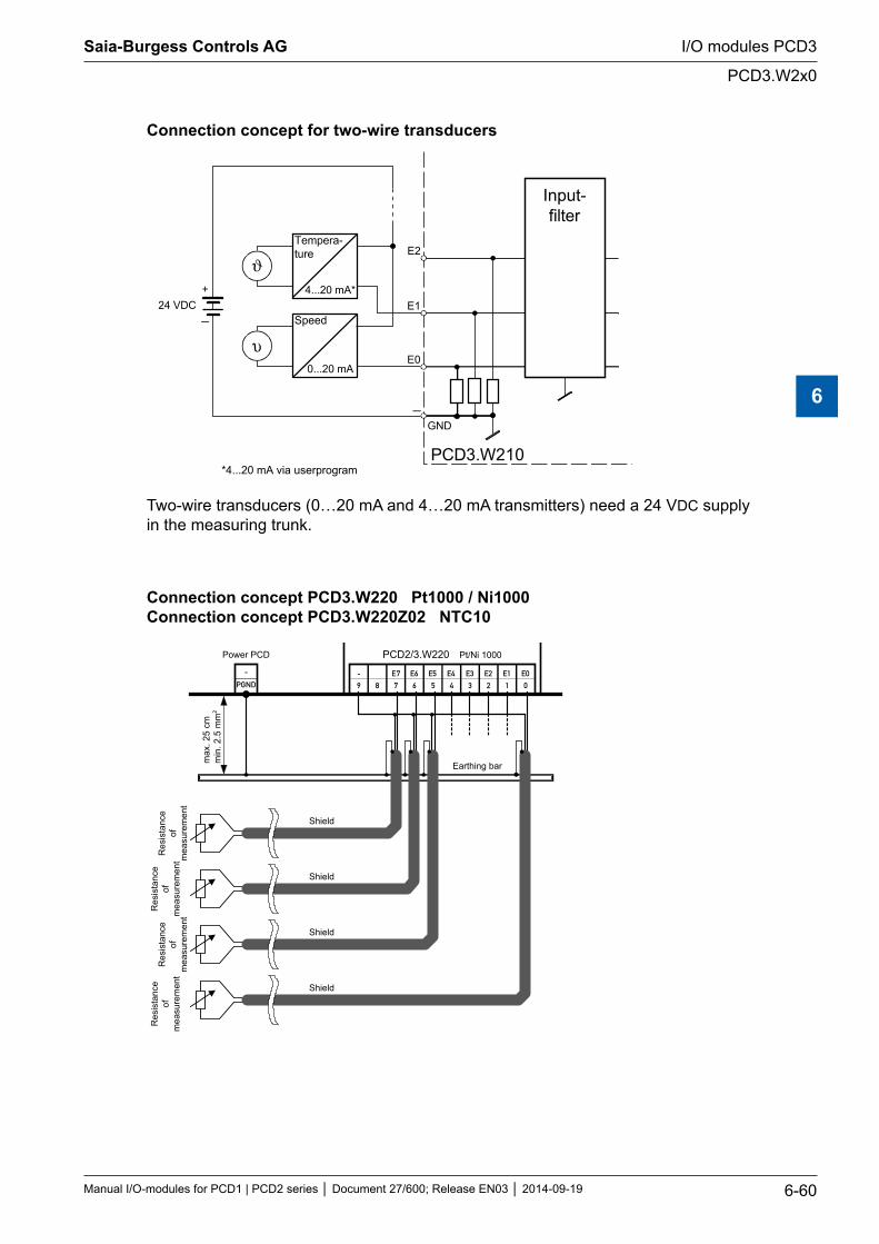
Connection concept for two-wire transducers
E1
E0
GND
PCD3.W210
4...20 mA*
0...20 mA
ϑ
υ
24 VDC
Tempera-ture
Speed
Input-filter
+
E2
*4...20 mA via userprogram
Two-wire transducers (0…20 mA and 4…20 mA transmitters) need a 24 VDC supply in the measuring trunk.
Connection concept PCD3.W220 Pt1000 / Ni1000 Connection concept PCD3.W220Z02 NTC10
-
9 8 7 6 5 4 3 2 1 0
- E7 E6 E5 E4 E3 E2 E1 E0PGND
PCD2/3.W220 Pt/Ni 1000
Earthing bar
Shield
Res
ista
nce
ofm
easu
rem
ent
Res
ista
nce
ofm
easu
rem
ent
Res
ista
nce
ofm
easu
rem
ent
Res
ista
nce
ofm
easu
rem
ent
Shield
Shield
Shield
max
. 25
cmm
in. 2
.5 m
m2
Power PCD
Saia-Burgess Controls AG
Manual I/O-modules for PCD1 | PCD2 series Document 27/600; Release EN03 2014-09-19 6-60
I/O modules PCD3
PCD3.W2x0
6
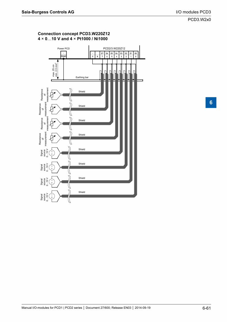
Connection concept PCD3.W220Z12 4 × 0…10 V and 4 × Pt1000 / Ni1000
-
9 8 7 6 5 4 3 2 1 0
- E7 E6 E5 E4 E3 E2 E1 E0PGND
PCD2/3.W220Z12
Earthing bar
Shield
Res
ista
nce
ofm
easu
rem
ent
Res
ista
nce
ofm
easu
rem
ent
Res
ista
nce
ofm
easu
rem
ent
Res
ista
nce
ofm
easu
rem
ent
Shield
Shield
Shield
Shield
Sign
also
urce
0…10
V
Sign
also
urce
0…10
V
Sign
also
urce
0…10
V
Sign
also
urce
0…10
V
Shield
Shield
Shield
Power PCD
max
. 25
cmm
in. 2
.5 m
m2
Saia-Burgess Controls AG
Manual I/O-modules for PCD1 | PCD2 series Document 27/600; Release EN03 2014-09-19 6-61
I/O modules PCD3
PCD3.W2x0
6
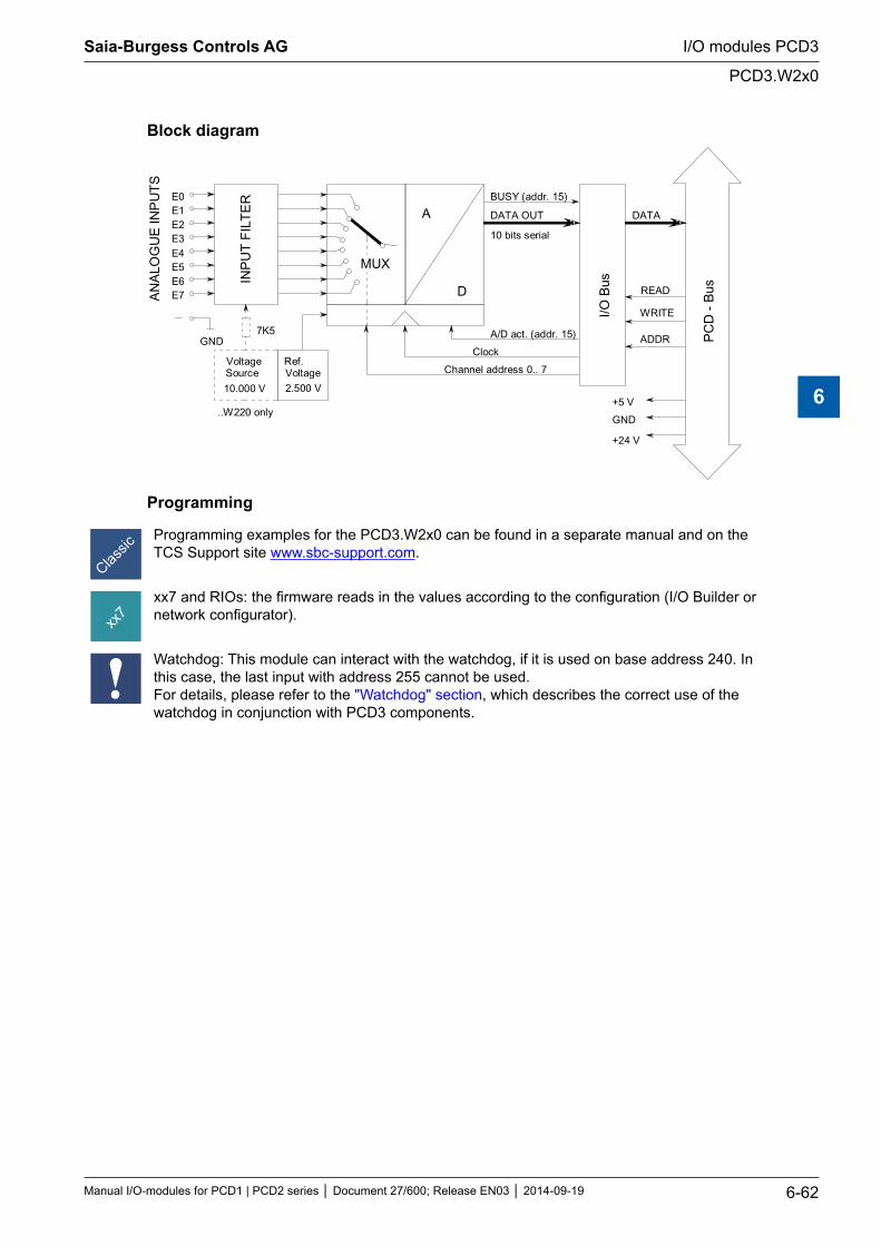
Block diagram
INP
UT
FIL
TE
RE0E1E2E3E4E5E6E7A
NA
LOG
UE
INP
UT
S
MUX
A
D
BUSY (addr. 15)
DATA OUT
10 bits serial
A/D act. (addr. 15)
Clock
Channel address 0.. 7
I/O B
us
DATA
READ
WRITE
ADDR PC
D -
Bus
+5 V
GND
+24 V
VoltageSource
10.000 V
7K5GND
Ref.Voltage2.500 V
..W220 only
Programming
Programming examples for the PCD3.W2x0 can be found in a separate manual and on the TCS Support site www.sbc-support.com.
xx7 and RIOs: the firmware reads in the values according to the configuration (I/O Builder or network configurator).
Watchdog: This module can interact with the watchdog, if it is used on base address 240. In this case, the last input with address 255 cannot be used. For details, please refer to the "Watchdog" section, which describes the correct use of the watchdog in conjunction with PCD3 components.
Saia-Burgess Controls AG
Manual I/O-modules for PCD1 | PCD2 series Document 27/600; Release EN03 2014-09-19 6-62
I/O modules PCD3
PCD3.W2x0
6
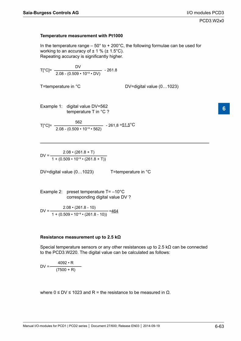
Temperature measurement with Pt1000
In the temperature range – 50° to + 200°C, the following formulae can be used for working to an accuracy of ± 1 % (± 1.5°C). Repeating accuracy is significantly higher.
T[°C]= - 261.8DV
2.08 - (0.509 • 10-³ • DV)
T=temperature in °C DV=digital value (0…1023)
Example 1: digital value DV=562 temperature T in °C ?
T[°C]= - 261,8562
2.08 - (0.509 • 10-³ • 562)=51.5°C
DV =2.08 • (261.8 + T)
1 + (0.509 • 10-³ • (261.8 + T))
DV=digital value (0…1023) T=temperature in °C
Example 2: preset temperature T= –10°C corresponding digital value DV ?
DV =2.08 • (261.8 - 10)
1 + (0.509 • 10-³ • (261.8 - 10))=464
Resistance measurement up to 2.5 kΩ
Special temperature sensors or any other resistances up to 2.5 kΩ can be connected to the PCD3.W220. The digital value can be calculated as follows:
DV =4092 • R
(7500 + R)
where 0 ≤ DV ≤ 1023 and R = the resistance to be measured in Ω.
Saia-Burgess Controls AG
Manual I/O-modules for PCD1 | PCD2 series Document 27/600; Release EN03 2014-09-19 6-63
I/O modules PCD3
PCD3.W2x0
6
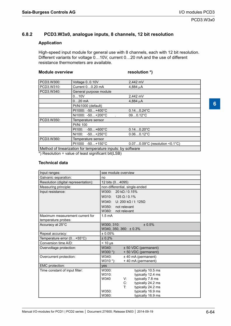
6.8.2 PCD3.W3x0, analogue inputs, 8 channels, 12 bit resolution
Application
High-speed input module for general use with 8 channels, each with 12 bit resolution. Different variants for voltage 0…10V, current 0…20 mA and the use of different resistance thermometers are available.
Module overview resolution *)
PCD3.W300: Voltage 0..0.10V 2,442 mVPCD3.W310: Current 0…0.20 mA 4,884 µAPCD3.W340: General purpose module
0…10V 2,442 mV0…20 mA 4,884 µAPt/Ni1000 (default)Pt1000: -50…+400°C 0.14…0.24°CNi1000: -50…+200°C . 09…0.12°C
PCD3.W350: Temperature sensorPt/Ni 100Pt100: -50…+600°C 0.14…0.20°CNi100: -50…+250°C 0.06…0.12°C
PCD3.W360: Temperature sensorPt1000 -50…+150°C 0.07…0.09°C (resolution <0.1°C)
Method of linearization for temperature inputs: by software*) Resolution = value of least significant bit(LSB)
Technical data
Input ranges: see module overviewGalvanic separation: noResolution (digital representation): 12 bits (0…4095)Measuring principle: non-differential, single-endedInput resistance: W300: 20 kΩ / 0.15%
W310: 125 Ω / 0.1% W340: U: 200 kΩ / I: 125Ω W350: not relevant W360: not relevant
Maximum measurement current for temperature probes:
1.5 mA
Accuracy at 25°C W300, 310: ± 0.5% W340, 350, 360: ± 0.3%
Repeat accuracy: ± 0.05%Temperature error (0…+55°C) ± 0.2%Conversion time A/D: < 10 μsOvervoltage protection: W340: ± 50 VDC (permanent)
W300 *): + 50 VDC (permanent)Overcurrent protection: W340: ± 40 mA (permanent)
W310 *): + 40 mA (permanent)EMC protection: yesTime constant of input filter: W300: typically 10.5 ms
W310: typically 12.4 ms W340 V: typically 7.8 ms C: typically 24.2 ms T: typically 24.2 ms W350: typically 16.9 ms W360: typically 16.9 ms
Saia-Burgess Controls AG
Manual I/O-modules for PCD1 | PCD2 series Document 27/600; Release EN03 2014-09-19 6-64
I/O modules PCD3
PCD3.W3x0
6
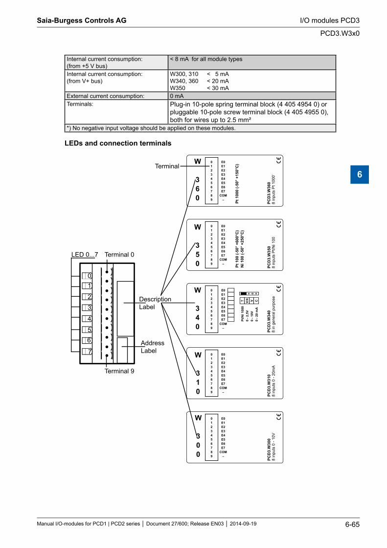
Internal current consumption: (from +5 V bus)
< 8 mA for all module types
Internal current consumption: (from V+ bus)
W300, 310 < 5 mA W340, 360 < 20 mA W350 < 30 mA
External current consumption: 0 mATerminals: Plug-in 10-pole spring terminal block (4 405 4954 0) or
pluggable 10-pole screw terminal block (4 405 4955 0), both for wires up to 2.5 mm²
*) No negative input voltage should be applied on these modules.
LEDs and connection terminals
01
2
3
4
56
7
LED 0...7 Terminal 0
DescriptionLabel
AddressLabel
0123456789
E0E1E2E3E4E5E6E7
COM–
Pt 1
00 (-
50° +
600°
C)
Ni 1
00 (-
50° +
250°
C)
PCD
3.W
305
8 in
puts
Pt
100
/Ni
0123456789
E0E1E2E3E4E5E6E7
COM–
PCD
3.W
301
8 in
puts
0 -
20m
A
0123456789
E0E1E2E3E4E5E6E7
COM–
PCD
3.W
300
8 in
puts
0 -
10V
Pt/N
i 100
00
- 2,5
V0
- 10V
0
- 20
mA
T V/4 V C
0123456789
PCD
3.W
340
8 in
gen
eral
pur
pose
E0E1E2E3E4E5E6E7
COM–
0123456789
E0E1E2E3E4E5E6E7
COM–
Pt 1
000
(-50°
+15
0°C
)
PCD
3.W
360
8 in
puts
Pt 1
000’
Terminal 9
Terminal
W
300
W
310
W
340
W
350
W
360
Saia-Burgess Controls AG
Manual I/O-modules for PCD1 | PCD2 series Document 27/600; Release EN03 2014-09-19 6-65
I/O modules PCD3
PCD3.W3x0
6
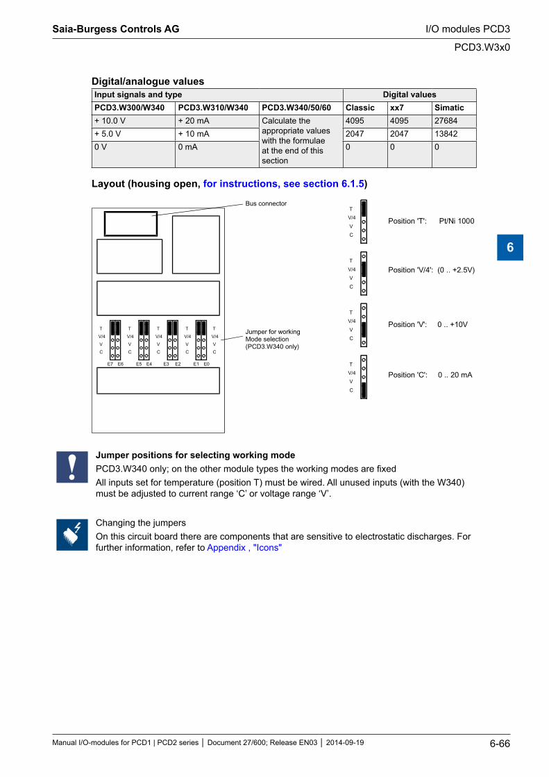
Digital/analogue valuesInput signals and type Digital values PCD3.W300/W340 PCD3.W310/W340 PCD3.W340/50/60 Classic xx7 Simatic+ 10.0 V + 20 mA Calculate the
appropriate values with the formulae at the end of this section
4095 4095 27684+ 5.0 V + 10 mA 2047 2047 138420 V 0 mA 0 0 0
Layout (housing open, for instructions, see section 6.1.5)
E7 E6 E5 E4 E3 E2 E1 E0
T
V/4
V
C
T
V/4
V
C
T
V/4
V
C
T
V/4
V
C
T
V/4
V
C
Bus connector
Jumper for workingMode selection(PCD3.W340 only)
T
V/4
V
C
T
V/4
V
C
T
V/4
V
C
T
V/4
V
C
Position 'T': Pt/Ni 1000
Position 'V/4': (0 .. +2.5V)
Position 'V': 0 .. +10V
Position 'C': 0 .. 20 mA
Jumper positions for selecting working modePCD3.W340 only; on the other module types the working modes are fixedAll inputs set for temperature (position T) must be wired. All unused inputs (with the W340) must be adjusted to current range ‘C’ or voltage range ‘V’.
Changing the jumpersOn this circuit board there are components that are sensitive to electrostatic discharges. For further information, refer to Appendix , "Icons"
Saia-Burgess Controls AG
Manual I/O-modules for PCD1 | PCD2 series Document 27/600; Release EN03 2014-09-19 6-66
I/O modules PCD3
PCD3.W3x0
6
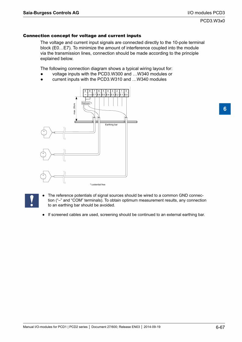
Connection concept for voltage and current inputsThe voltage and current input signals are connected directly to the 10-pole terminal block (E0…E7). To minimize the amount of interference coupled into the module via the transmission lines, connection should be made according to the principle explained below.
The following connection diagram shows a typical wiring layout for: voltage inputs with the PCD3.W300 and …W340 modules or current inputs with the PCD3.W310 and …W340 modules
89
E 6
67
E 4
45
E 1
23
E 0
01
E 3 E 2E 5E 7
Earthing bar
max
. 20c
m
C O M
Distributor *)
*) potential free
The reference potentials of signal sources should be wired to a common GND connec-tion (“–” and “COM” terminals). To obtain optimum measurement results, any connection to an earthing bar should be avoided.
If screened cables are used, screening should be continued to an external earthing bar.
Saia-Burgess Controls AG
Manual I/O-modules for PCD1 | PCD2 series Document 27/600; Release EN03 2014-09-19 6-67
I/O modules PCD3
PCD3.W3x0
6
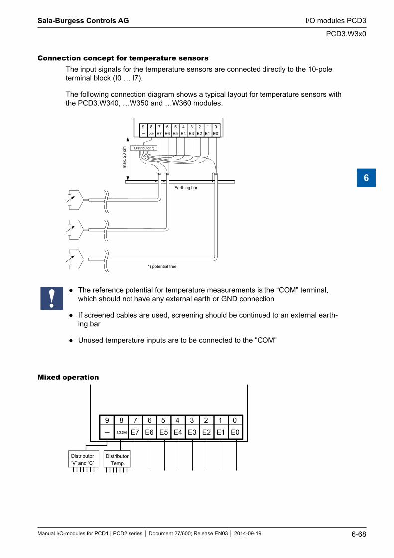
Connection concept for temperature sensorsThe input signals for the temperature sensors are connected directly to the 10-pole terminal block (I0 … I7).
The following connection diagram shows a typical layout for temperature sensors with the PCD3.W340, …W350 and …W360 modules.
8 9 E6 6 7
E4 4 5
E1 2 3
E0 0 1
E3 E2 E5 E7 COM
Distributor *)
Earthing bar
max
. 20
cm
*) potential free
The reference potential for temperature measurements is the “COM” terminal, which should not have any external earth or GND connection
If screened cables are used, screening should be continued to an external earth-ing bar
Unused temperature inputs are to be connected to the "COM"
Mixed operation
89
E6
67
E4
4 5
E1
2 3
E0
0 1
E3 E2E5E7COM
Distributor‘V’ and ‘C’
Distributor Temp.
Saia-Burgess Controls AG
Manual I/O-modules for PCD1 | PCD2 series Document 27/600; Release EN03 2014-09-19 6-68
I/O modules PCD3
PCD3.W3x0
6
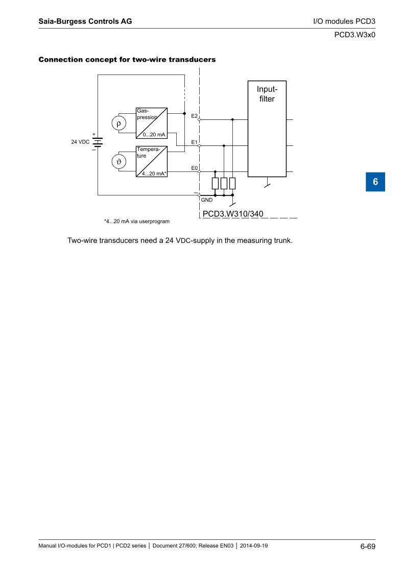
Connection concept for two-wire transducers
E1
E0
GND
PCD3.W310/340
0...20 mA
4...20 mA*
ρ
ϑ
24 VDC
Gas-pression
Tempera-ture
Input-filter
+
E2
*4...20 mA via userprogram
Two-wire transducers need a 24 VDC-supply in the measuring trunk.
Saia-Burgess Controls AG
Manual I/O-modules for PCD1 | PCD2 series Document 27/600; Release EN03 2014-09-19 6-69
I/O modules PCD3
PCD3.W3x0
6
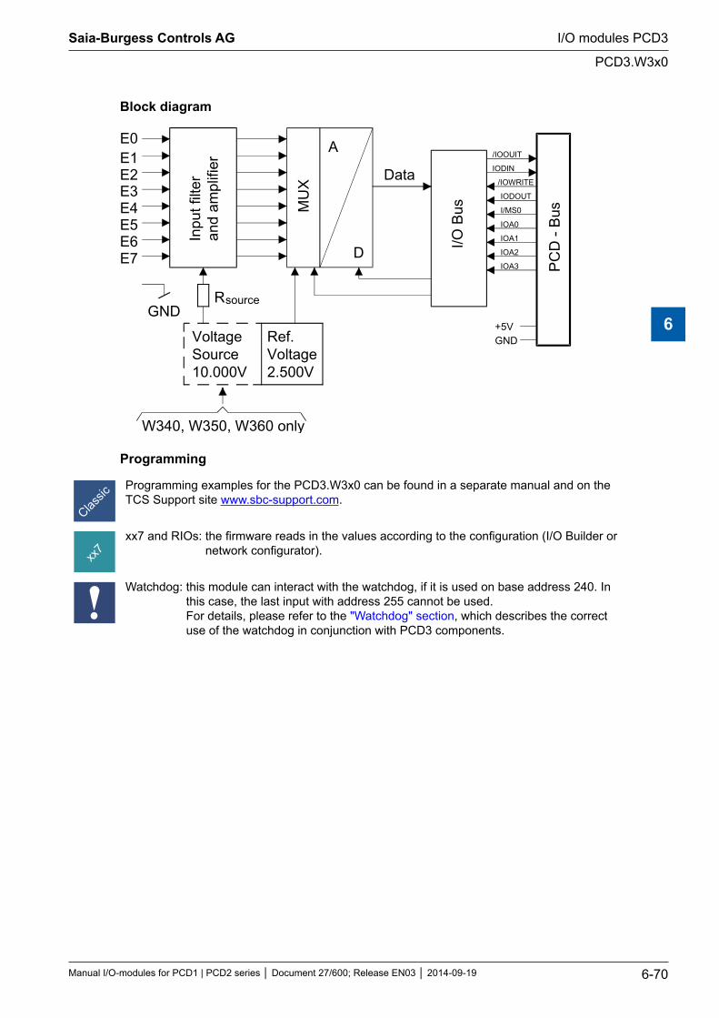
Block diagram
E0E1E2E3E4E5E6E7
GNDRsource
VoltageSource10.000V
Ref.Voltage2.500V
Inpu
t filt
eran
d am
plifi
er
MU
X
A
D
Data
I/O B
us
PC
D -
Bus
+5VGND
/IOOUIT
IODIN
/IOWRITE
IODOUT
I/MS0
IOA0
IOA1
IOA2
IOA3
W340, W350, W360 only
Programming
Programming examples for the PCD3.W3x0 can be found in a separate manual and on the TCS Support site www.sbc-support.com.
xx7 and RIOs: the firmware reads in the values according to the configuration (I/O Builder or network configurator).
Watchdog: this module can interact with the watchdog, if it is used on base address 240. In this case, the last input with address 255 cannot be used. For details, please refer to the "Watchdog" section, which describes the correct use of the watchdog in conjunction with PCD3 components.
Saia-Burgess Controls AG
Manual I/O-modules for PCD1 | PCD2 series Document 27/600; Release EN03 2014-09-19 6-70
I/O modules PCD3
PCD3.W3x0
6
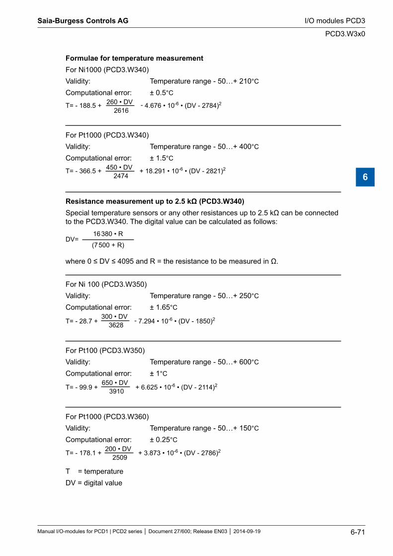
Formulae for temperature measurementFor Ni1000 (PCD3.W340)Validity: Temperature range - 50…+ 210°C
Computational error: ± 0.5°C260 • DV
2616T= - 188.5 + - 4.676 • 10-6 • (DV - 2784)2
For Pt1000 (PCD3.W340)Validity: Temperature range - 50…+ 400°C
Computational error: ± 1.5°C450 • DV
2474T= - 366.5 + + 18.291 • 10-6 • (DV - 2821)2
Resistance measurement up to 2.5 kΩ (PCD3.W340)Special temperature sensors or any other resistances up to 2.5 kΩ can be connected to the PCD3.W340. The digital value can be calculated as follows:
DV=16 380 • R
(7 500 + R)
where 0 ≤ DV ≤ 4095 and R = the resistance to be measured in Ω.
For Ni 100 (PCD3.W350)Validity: Temperature range - 50…+ 250°C
Computational error: ± 1.65°C300 • DV
3628T= - 28.7 + - 7.294 • 10-6 • (DV - 1850)2
For Pt100 (PCD3.W350)Validity: Temperature range - 50…+ 600°C
Computational error: ± 1°C650 • DV
3910T= - 99.9 + + 6.625 • 10-6 • (DV - 2114)2
For Pt1000 (PCD3.W360)Validity: Temperature range - 50…+ 150°C
Computational error: ± 0.25°C200 • DV
2509T= - 178.1 + + 3.873 • 10-6 • (DV - 2786)2
T = temperatureDV = digital value
Saia-Burgess Controls AG
Manual I/O-modules for PCD1 | PCD2 series Document 27/600; Release EN03 2014-09-19 6-71
I/O modules PCD3
PCD3.W3x0
6
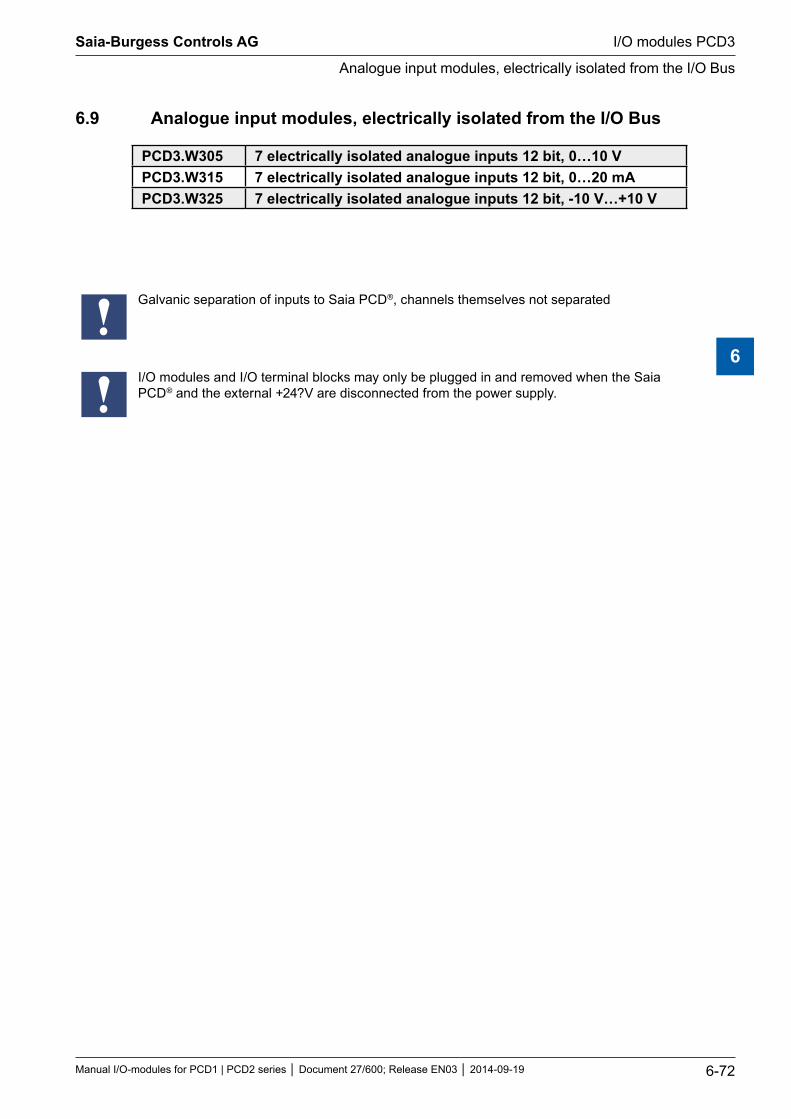
6.9 Analogue input modules, electrically isolated from the I/O Bus
PCD3.W305 7 electrically isolated analogue inputs 12 bit, 0…10 VPCD3.W315 7 electrically isolated analogue inputs 12 bit, 0…20 mAPCD3.W325 7 electrically isolated analogue inputs 12 bit, -10 V…+10 V
Galvanic separation of inputs to Saia PCD®, channels themselves not separated
I/O modules and I/O terminal blocks may only be plugged in and removed when the Saia PCD® and the external +24?V are disconnected from the power supply.
Saia-Burgess Controls AG
Manual I/O-modules for PCD1 | PCD2 series Document 27/600; Release EN03 2014-09-19 6-72
I/O modules PCD3
Analogue input modules, electrically isolated from the I/O Bus
6
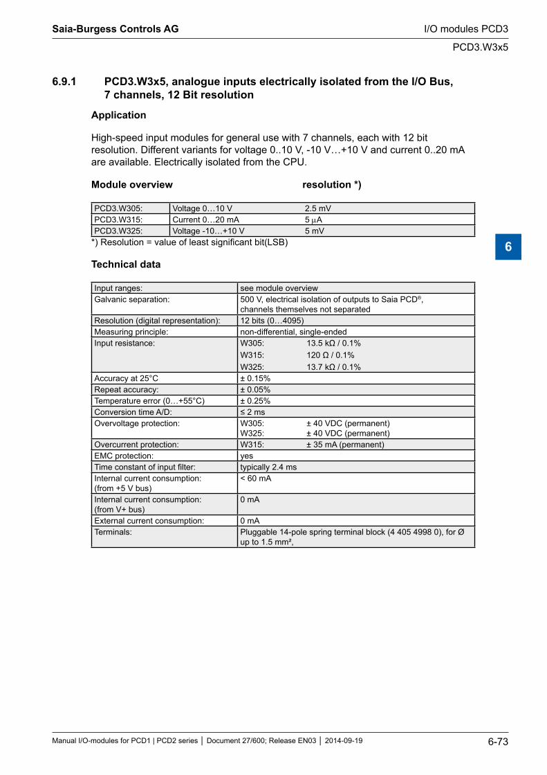
6.9.1 PCD3.W3x5, analogue inputs electrically isolated from the I/O Bus, 7 channels, 12 Bit resolution
Application
High-speed input modules for general use with 7 channels, each with 12 bit resolution. Different variants for voltage 0..10 V, -10 V…+10 V and current 0..20 mA are available. Electrically isolated from the CPU.
Module overview resolution *)
PCD3.W305: Voltage 0…10 V 2.5 mVPCD3.W315: Current 0…20 mA 5 µAPCD3.W325: Voltage -10…+10 V 5 mV
*) Resolution = value of least significant bit(LSB)
Technical data
Input ranges: see module overviewGalvanic separation: 500 V, electrical isolation of outputs to Saia PCD®,
channels themselves not separatedResolution (digital representation): 12 bits (0…4095)Measuring principle: non-differential, single-endedInput resistance: W305: 13.5 kΩ / 0.1%
W315: 120 Ω / 0.1% W325: 13.7 kΩ / 0.1%
Accuracy at 25°C ± 0.15%Repeat accuracy: ± 0.05%Temperature error (0…+55°C) ± 0.25%Conversion time A/D: ≤ 2 msOvervoltage protection: W305: ± 40 VDC (permanent)
W325: ± 40 VDC (permanent)Overcurrent protection: W315: ± 35 mA (permanent)EMC protection: yesTime constant of input filter: typically 2.4 msInternal current consumption: (from +5 V bus)
< 60 mA
Internal current consumption: (from V+ bus)
0 mA
External current consumption: 0 mATerminals: Pluggable 14-pole spring terminal block (4 405 4998 0), for Ø
up to 1.5 mm²,
Saia-Burgess Controls AG
Manual I/O-modules for PCD1 | PCD2 series Document 27/600; Release EN03 2014-09-19 6-73
I/O modules PCD3
PCD3.W3x5
6
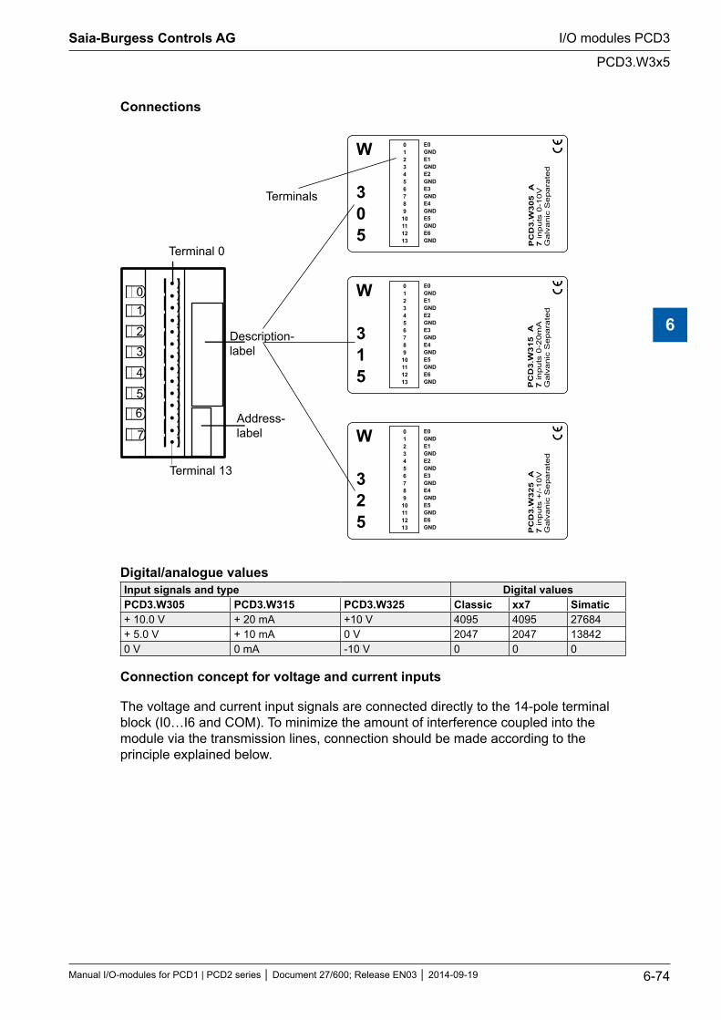
Connections
01
2
3
4
56
7
Description-label
Address-label
Terminal 13
0123456789
10111213 P
CD
3.W
305 A
7in
puts
0-1
0V
Galv
anic
Separa
ted
W
305
E0GNDE1GNDE2GNDE3GNDE4GNDE5GNDE6GND
0123456789
10111213 P
CD
3.W
315
A7
inputs
0-2
0m
AG
alv
anic
Separa
ted
W
315
E0GNDE1GNDE2GNDE3GNDE4GNDE5GNDE6GND
0123456789
10111213 P
CD
3.W
325 A
7in
puts
+/-
10V
Galv
anic
Separa
ted
W
325
E0GNDE1GNDE2GNDE3GNDE4GNDE5GNDE6GND
Terminal 0
Terminals
Digital/analogue valuesInput signals and type Digital values PCD3.W305 PCD3.W315 PCD3.W325 Classic xx7 Simatic+ 10.0 V + 20 mA +10 V 4095 4095 27684+ 5.0 V + 10 mA 0 V 2047 2047 138420 V 0 mA -10 V 0 0 0
Connection concept for voltage and current inputs
The voltage and current input signals are connected directly to the 14-pole terminal block (I0…I6 and COM). To minimize the amount of interference coupled into the module via the transmission lines, connection should be made according to the principle explained below.
Saia-Burgess Controls AG
Manual I/O-modules for PCD1 | PCD2 series Document 27/600; Release EN03 2014-09-19 6-74
I/O modules PCD3
PCD3.W3x5
6
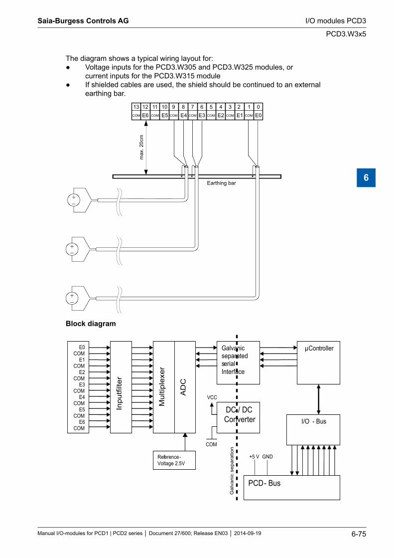
The diagram shows a typical wiring layout for: Voltage inputs for the PCD3.W305 and PCD3.W325 modules, or current inputs for the PCD3.W315 module If shielded cables are used, the shield should be continued to an external earthing bar.
max
.20c
m
E0 E1 E2 E3 E4 E5 E6 COM COM COM COM COM COM COM
0 1 2 3 4 5 6 7 8 9 10 11 12 13
Earthing bar
Block diagram
Inpu
tfilte
r
E0 COM
E1 COM
E2 COM
E3 COM
E4 COM
E5 COM
E6 COM
Mul
tiple
xer
AD
C
Reference- Voltage 2.5V
μController
PCD - Bus
I/O - Bus DC / DC Converter
Galvanic separated serial Interface
Gal
vani
c se
para
tion
VCC
COM
+5 V GND
Saia-Burgess Controls AG
Manual I/O-modules for PCD1 | PCD2 series Document 27/600; Release EN03 2014-09-19 6-75
I/O modules PCD3
PCD3.W3x5
6
Programming
For programming the modules PCD3.W3x5, an FBox is available.
xx7 and RIOs: the firmware reads in the values according to the configuration (I/O Builder or network configurator).
Watchdog: This module can be used on all base addresses; there is no interaction with the watchdog on the CPUs.
Saia-Burgess Controls AG
Manual I/O-modules for PCD1 | PCD2 series Document 27/600; Release EN03 2014-09-19 6-76
I/O modules PCD3
PCD3.W3x5
6
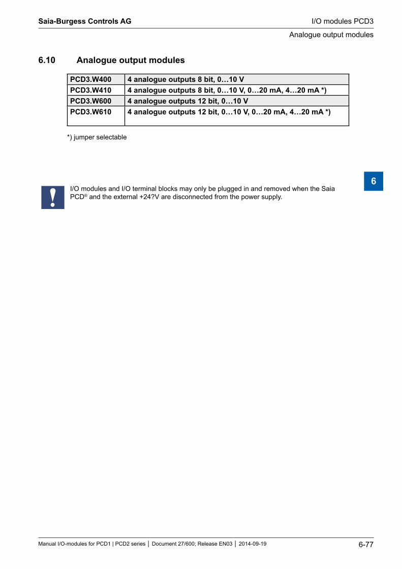
6.10 Analogue output modules
PCD3.W400 4 analogue outputs 8 bit, 0…10 VPCD3.W410 4 analogue outputs 8 bit, 0…10 V, 0…20 mA, 4…20 mA *)PCD3.W600 4 analogue outputs 12 bit, 0…10 VPCD3.W610 4 analogue outputs 12 bit, 0…10 V, 0…20 mA, 4…20 mA *)
*) jumper selectable
I/O modules and I/O terminal blocks may only be plugged in and removed when the Saia PCD® and the external +24?V are disconnected from the power supply.
Saia-Burgess Controls AG
Manual I/O-modules for PCD1 | PCD2 series Document 27/600; Release EN03 2014-09-19 6-77
I/O modules PCD3
Analogue output modules
6
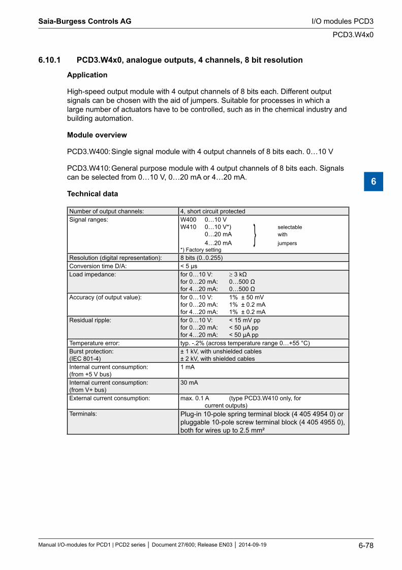
6.10.1 PCD3.W4x0, analogue outputs, 4 channels, 8 bit resolution
Application
High-speed output module with 4 output channels of 8 bits each. Different output signals can be chosen with the aid of jumpers. Suitable for processes in which a large number of actuators have to be controlled, such as in the chemical industry and building automation.
Module overview
PCD3.W400: Single signal module with 4 output channels of 8 bits each. 0…10 V
PCD3.W410: General purpose module with 4 output channels of 8 bits each. Signals can be selected from 0…10 V, 0…20 mA or 4…20 mA.
Technical data
Number of output channels: 4, short circuit protectedSignal ranges: W400 0…10 V
W410 0…10 V*) selectable 0…20 mA with 4…20 mA jumpers *) Factory setting
Resolution (digital representation): 8 bits (0..0.255)Conversion time D/A: < 5 µsLoad impedance: for 0…10 V: ≥ 3 kΩ
for 0…20 mA: 0…500 Ω for 4…20 mA: 0…500 Ω
Accuracy (of output value): for 0…10 V: 1% ± 50 mV for 0…20 mA: 1% ± 0.2 mA for 4…20 mA: 1% ± 0.2 mA
Residual ripple: for 0…10 V: < 15 mV pp for 0…20 mA: < 50 µA pp for 4…20 mA: < 50 µA pp
Temperature error: typ. -.2% (across temperature range 0…+55 °C)Burst protection: (IEC 801-4)
± 1 kV, with unshielded cables ± 2 kV, with shielded cables
Internal current consumption: (from +5 V bus)
1 mA
Internal current consumption: (from V+ bus)
30 mA
External current consumption: max. 0.1 A (type PCD3.W410 only, for current outputs)
Terminals: Plug-in 10-pole spring terminal block (4 405 4954 0) or pluggable 10-pole screw terminal block (4 405 4955 0), both for wires up to 2.5 mm²
Saia-Burgess Controls AG
Manual I/O-modules for PCD1 | PCD2 series Document 27/600; Release EN03 2014-09-19 6-78
I/O modules PCD3
PCD3.W4x0
6
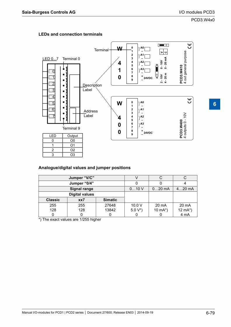
LEDs and connection terminals
01
2
3
4
56
7
LED 0...7 Terminal 0
DescriptionLabel
AddressLabel
0123456789
A0–
A1–
A2–
A3–+– 24VDC
PCD
3.W
400
4 ou
tput
s 0
- 10V
0123456789
A0–
A1–
A2–
A3–+– 24VDC
2 - 1
0V0
- 10V
4
- 20
m0
- 20
mA
V C
40
PCD
3.W
410
4 ou
t gen
eral
pur
pose
Terminal 9
Terminal W
410
W
400
LED Output0 O01 O12 O23 O3
Analogue/digital values and jumper positions
Jumper “V/C” V C CJumper “0/4” 0 0 4Signal range 0…10 V 0…20 mA 4…20 mADigital values
Classic xx7 Simatic255128
0
255128
0
2764813842
0
10.0 V5.0 V*)
0
20 mA10 mA*)
0
20 mA12 mA*)
4 mA*) The exact values are 1/255 higher
Saia-Burgess Controls AG
Manual I/O-modules for PCD1 | PCD2 series Document 27/600; Release EN03 2014-09-19 6-79
I/O modules PCD3
PCD3.W4x0
6
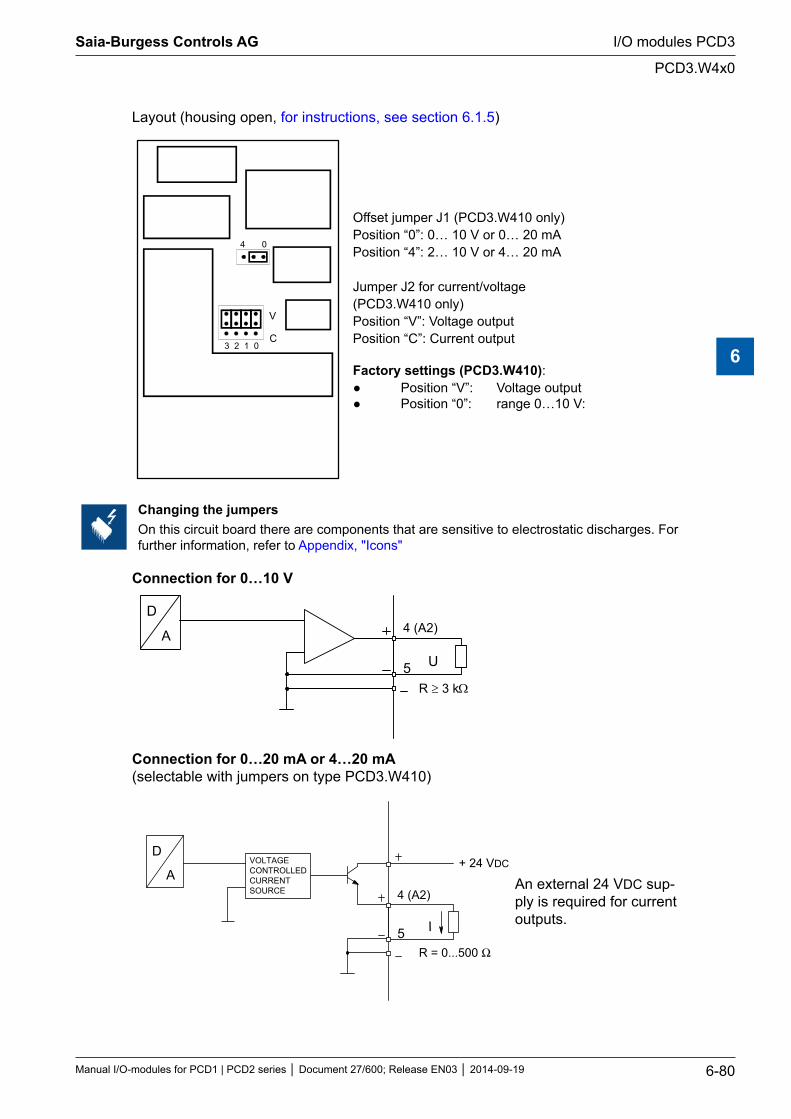
Layout (housing open, for instructions, see section 6.1.5)
23 1 0
V
C
4 0
Offset jumper J1 (PCD3.W410 only)Position “0”: 0… 10 V or 0… 20 mAPosition “4”: 2… 10 V or 4… 20 mA
Jumper J2 for current/voltage(PCD3.W410 only)Position “V”: Voltage outputPosition “C”: Current output
Factory settings (PCD3.W410): Position “V”: Voltage output Position “0”: range 0…10 V:
Changing the jumpersOn this circuit board there are components that are sensitive to electrostatic discharges. For further information, refer to Appendix, "Icons"
Connection for 0…10 V
4 (A2)D
A
5 U
R ≥ 3 kΩ
Connection for 0…20 mA or 4…20 mA (selectable with jumpers on type PCD3.W410)
4 (A2)
5 I
R = 0...500 Ω
D
AVOLTAGECONTROLLEDCURRENTSOURCE
+ 24 VDC
An external 24 VDC sup-ply is required for current outputs.
Saia-Burgess Controls AG
Manual I/O-modules for PCD1 | PCD2 series Document 27/600; Release EN03 2014-09-19 6-80
I/O modules PCD3
PCD3.W4x0
6
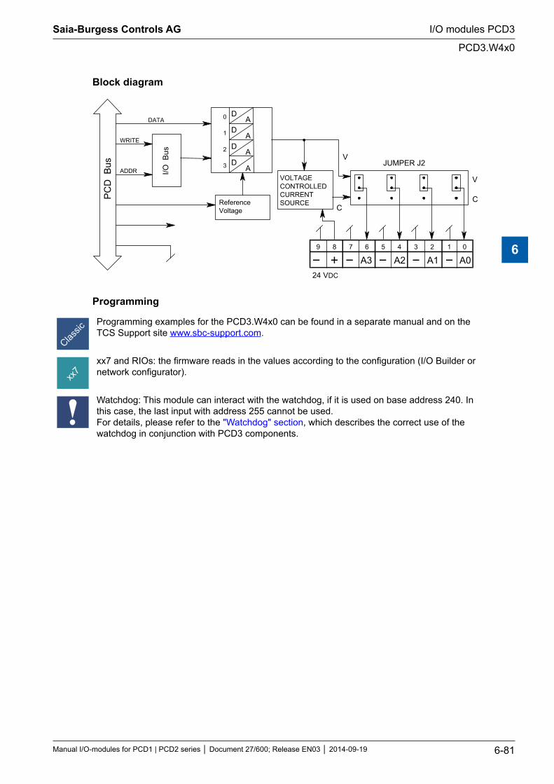
Block diagram
D A
D A
D A
D A
2
3
V
C
9 8 7 6 5 4 3 2 1 0
A0 A1 A2 A3
V
C
0
1
I/O B
us
PC
D B
us
ReferenceVoltage
DATA
WRITE
ADDRJUMPER J2
24 VDC
VOLTAGECONTROLLEDCURRENTSOURCE
Programming
Programming examples for the PCD3.W4x0 can be found in a separate manual and on the TCS Support site www.sbc-support.com.
xx7 and RIOs: the firmware reads in the values according to the configuration (I/O Builder or network configurator).
Watchdog: This module can interact with the watchdog, if it is used on base address 240. In this case, the last input with address 255 cannot be used. For details, please refer to the "Watchdog" section, which describes the correct use of the watchdog in conjunction with PCD3 components.
Saia-Burgess Controls AG
Manual I/O-modules for PCD1 | PCD2 series Document 27/600; Release EN03 2014-09-19 6-81
I/O modules PCD3
PCD3.W4x0
6
6.10.2 PCD3.W6x0, analogue outputs, 4 channels, 12 bit resolution
Application
High-speed output module for general use with 4 channels, each with 12 bit resolu-tion. Different variants for voltage 0…10V, -10…+10V and current 0…20 mA are available.
Module overview
PCD3.W600: Unipolar voltage outputs 0…10 V PCD3.W610: Bipolar voltage outputs -10 V…+10 V, switchable to unipolar voltage 0…10 V / current 0…20 mA
Technical data Resolution
Number of output channels: 4, short circuit protectedSignal range: W600: 0…+10 V 2.442 mV
W610: -10 V…+10 V 4.884 mV selectable 0…+10 V 2.442.mV with 0…20 mA 4.884 μA jumper
Galvanic separation: noResolution (digital representation): 12 bits (0…4095)Conversion time D/A: typ. 10 μsLoad impedance Voltage: > 3 kΩ
Current: < 500 ΩAccuracy at 25°C (of output value) Voltage: ± 0.5 %
Current: ± 0.8 % *)Temperature error: Voltage: ± 0.1 % (over temperature range
Current: ± 0.2 % 0…+55 °C)Internal current consumption: (from +5 V bus)
W600: max. 4 mA W610: max. 110 mA
Internal current consumption: (from V+ bus)
W600: max. 20 mA W610: 0 mA
External current consumption: max. 100 mA (type PCD3.W610 only, for current outputs)Terminals: Plug-in 10-pole spring terminal block (4 405 4954 0) or
pluggable 10-pole screw terminal block (4 405 4955 0), both for wires up to 2.5 mm²
*) Note on current outputs: Since for some applications it is important to be able to reach the outside limit values of the range (0 mA, 20 mA), current outputs have been laid out according to the following charac-teristic line:During start-up, a voltage of 5 V is sent to all outputs of the W600 module. The start-up phase lasts 40 ms, then 0 V is sent to the outputs.
Saia-Burgess Controls AG
Manual I/O-modules for PCD1 | PCD2 series Document 27/600; Release EN03 2014-09-19 6-82
I/O modules PCD3
PCD3.W6x0
6
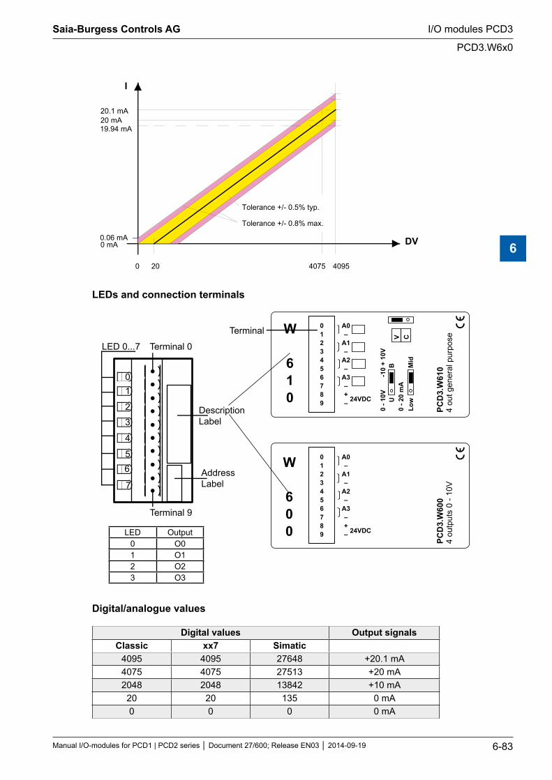
0 mA
20 mA20.1 mA
I
DV
Tolerance +/- 0.5% typ.
0 20 4075 4095
19.94 mA
0.06 mA
Tolerance +/- 0.8% max.
LEDs and connection terminals
01
2
3
4
56
7
LED 0...7 Terminal 0
DescriptionLabel
AddressLabel
0123456789
A0–
A1–
A2–
A3–+– 24VDC
PCD
3.W
600
4 ou
tput
s 0
- 10V
0123456789
A0–
A1–
A2–
A3–+– 24VDC
0 - 1
0V-1
0 +
10V
0 - 2
0 m
AV C
UB
Low
Mid
PCD
3.W
610
4 ou
t gen
eral
pur
pose
Terminal 9
Terminal W
610
W
600LED Output
0 O01 O12 O23 O3
Digital/analogue values
Digital values Output signalsClassic xx7 Simatic
4095 4095 27648 +20.1 mA4075 4075 27513 +20 mA2048 2048 13842 +10 mA
20 20 135 0 mA0 0 0 0 mA
Saia-Burgess Controls AG
Manual I/O-modules for PCD1 | PCD2 series Document 27/600; Release EN03 2014-09-19 6-83
I/O modules PCD3
PCD3.W6x0
6
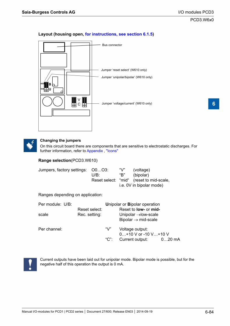
Layout (housing open, for instructions, see section 6.1.5)
Bus connector
B
U
VC
Jumper ‘unipolar/bipolar’ (W610 only)
Jumper ‘voltage/current’ (W610 only)
mid
low
Jumper ‘reset select’ (W610 only)
Changing the jumpersOn this circuit board there are components that are sensitive to electrostatic discharges. For further information, refer to Appendix , "Icons"
Range selection(PCD3.W610)
Jumpers, factory settings: O0…O3: “V” (voltage) U/B: “B” (bipolar) Reset select: “mid“ (reset to mid-scale, i.e. 0V in bipolar mode)
Ranges depending on application:
Per module: U/B: Unipolar or Bipolar operation Reset select: Reset to low- or mid- scale Rec. setting: Unipolar →low-scale Bipolar → mid-scale
Per channel: “V” Voltage output: 0…+10 V or -10 V…+10 V “C”: Current output: 0…20 mA
Current outputs have been laid out for unipolar mode. Bipolar mode is possible, but for the negative half of this operation the output is 0 mA.
Saia-Burgess Controls AG
Manual I/O-modules for PCD1 | PCD2 series Document 27/600; Release EN03 2014-09-19 6-84
I/O modules PCD3
PCD3.W6x0
6
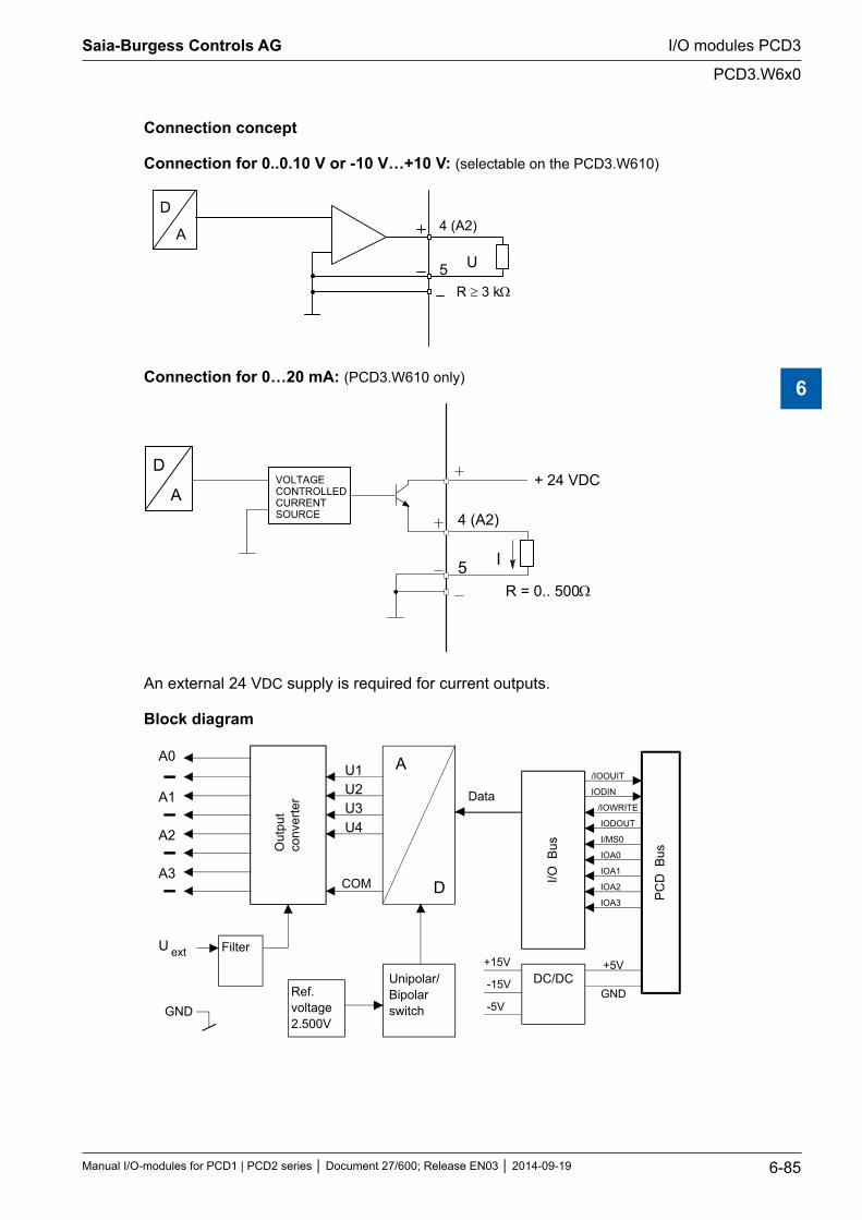
Connection concept
Connection for 0..0.10 V or -10 V…+10 V: (selectable on the PCD3.W610)
4 (A2)D
A
5 U
R ≥ 3 kΩ
Connection for 0…20 mA: (PCD3.W610 only)
4 (A2)
D
A
5 I
+ 24 VDC
R = 0.. 500 Ω
VOLTAGECONTROLLEDCURRENTSOURCE
An external 24 VDC supply is required for current outputs.
Block diagram
A0
A1
A2
A3
Out
put
conv
erte
r
A
D
Data
I/O B
us
PC
D B
us
+5V
GND
/IOOUIT
IODIN
/IOWRITE
IODOUT
I/MS0
IOA0
IOA1
IOA2
IOA3
+15V
-15V
-5V
Filter
Ref.voltage2.500V
Unipolar/Bipolarswitch
DC/DC
U ext
GND
U1U2U3U4
COM
Saia-Burgess Controls AG
Manual I/O-modules for PCD1 | PCD2 series Document 27/600; Release EN03 2014-09-19 6-85
I/O modules PCD3
PCD3.W6x0
6
Programming
Programming examples for the PCD3.W6x0 can be found on the TCS Support site www.sbc-support.com.
xx7 and RIOs: the firmware reads in the values according to the configuration (I/O Builder or network configurator).
Watchdog: This module can interact with the watchdog, if it is used on base address 240. In this case, the last input with address 255 cannot be used. For details, please refer to the "Watchdog" section, which describes the correct use of the watchdog in conjunction with PCD3 components.
Saia-Burgess Controls AG
Manual I/O-modules for PCD1 | PCD2 series Document 27/600; Release EN03 2014-09-19 6-86
I/O modules PCD3
PCD3.W6x0
6

6.11 Analogue output modules, electrically isolated from the I/O Bus
PCD3.W605 6 electrically isolated analogue outputs 10 bit, 0…10 VPCD3.W615 4 electrically isolated analogue outputs 10 bit, 0…20 mAPCD3.W625 6 electrically isolated analogue outputs 10 bit, -10 V…+10 V
Galvanic separation of outputs to Saia PCD®, channels themselves not separated
I/O modules and I/O terminal blocks may only be plugged in and removed when the Saia PCD® and the external +24?V are disconnected from the power supply.
Saia-Burgess Controls AG
Manual I/O-modules for PCD1 | PCD2 series Document 27/600; Release EN03 2014-09-19 6-87
I/O modules PCD3
Analogue output modules, electrically isolated from the I/O Bus
6
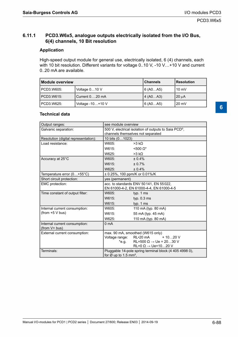
6.11.1 PCD3.W6x5, analogue outputs electrically isolated from the I/O Bus, 6(4) channels, 10 Bit resolution
Application
High-speed output module for general use, electrically isolated, 6 (4) channels, each with 10 bit resolution. Different variants for voltage 0..10 V, -10 V…+10 V and current 0..20 mA are available.
Module overview Channels Resolution
PCD3.W605: Voltage 0…10 V 6 (A0…A5) 10 mV
PCD3.W615: Current 0….20 mA 4 (A0…A3) 20 µA
PCD3.W625: Voltage -10…+10 V 6 (A0…A5) 20 mV
Technical data
Output ranges: see module overviewGalvanic separation: 500 V, electrical isolation of outputs to Saia PCD®,
channels themselves not separatedResolution (digital representation): 10 bits (0…1023)Load resistance: W605: >3 kΩ
W615: <500 Ω* W625: >3 kΩ
Accuracy at 25°C W605: ± 0.4% W615: ± 0.7% W625: ± 0.4%
Temperature error (0…+55°C) ± 0.25%, 100 ppm/K or 0.01%/KShort circuit protection: yes (permanent)EMC protection: acc. to standards ENV 50 141, EN 55 022,
EN 61000-4-2, EN 61000-4-4, EN 61000-4-5Time constant of output filter: W605: typ. 1 ms
W615: typ. 0.3 ms W615: typ. 1 ms
Internal current consumption: (from +5 V bus)
W605: 110 mA (typ. 80 mA) W615: 55 mA (typ. 45 mA) W625: 110 mA (typ. 80 mA)
Internal current consumption: (from V+ bus)
0 mA
External current consumption: max. 90 mA, smoothed (W615 only) Voltage range: RL•20 mA + 10…20 V *e.g. RL=500 Ω → Ue = 20…30 V RL=0 Ω → Ue=10…20 V
Terminals: Pluggable 14-pole spring terminal block (4 405 4998 0), for Ø up to 1.5 mm²,
Saia-Burgess Controls AG
Manual I/O-modules for PCD1 | PCD2 series Document 27/600; Release EN03 2014-09-19 6-88
I/O modules PCD3
PCD3.W6x5
6
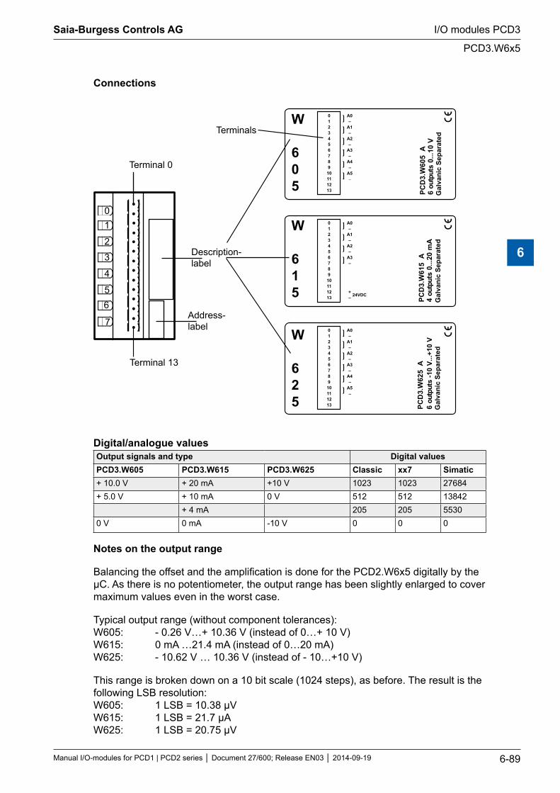
Connections
012345678910111213
A0–
A1–
A2–
A3–
A4
A5–
–
5 A
26W.3
DCP 6
ts -1
0 V.
..+10
V
uptuo
W
625 G
alva
nic
Sepa
rate
d
012345678910111213
A0–
A1–
A2–
A3–
+– 24VDC
5 A
16W.3
DCP 4
ts 0
...20
mA
uptuo
W
615
Gal
vani
c Se
para
ted
012345678910111213
A0–
A1–
A2–
A3–
A4
A5–
–
5 A
06W.3
DCP 6
ts 0
...10
Vuptuo
W
605
Gal
vani
c Se
para
ted
Description-label
Address-label
Terminal 13
01
2
3
4
56
7
Terminal 0
Terminals
Digital/analogue valuesOutput signals and type Digital valuesPCD3.W605 PCD3.W615 PCD3.W625 Classic xx7 Simatic+ 10.0 V + 20 mA +10 V 1023 1023 27684+ 5.0 V + 10 mA 0 V 512 512 13842
+ 4 mA 205 205 55300 V 0 mA -10 V 0 0 0
Notes on the output range
Balancing the offset and the amplification is done for the PCD2.W6x5 digitally by the µC. As there is no potentiometer, the output range has been slightly enlarged to cover maximum values even in the worst case.
Typical output range (without component tolerances): W605: - 0.26 V…+ 10.36 V (instead of 0…+ 10 V) W615: 0 mA …21.4 mA (instead of 0…20 mA) W625: - 10.62 V … 10.36 V (instead of - 10…+10 V)
This range is broken down on a 10 bit scale (1024 steps), as before. The result is the following LSB resolution: W605: 1 LSB = 10.38 µV W615: 1 LSB = 21.7 µA W625: 1 LSB = 20.75 µV
Saia-Burgess Controls AG
Manual I/O-modules for PCD1 | PCD2 series Document 27/600; Release EN03 2014-09-19 6-89
I/O modules PCD3
PCD3.W6x5
6
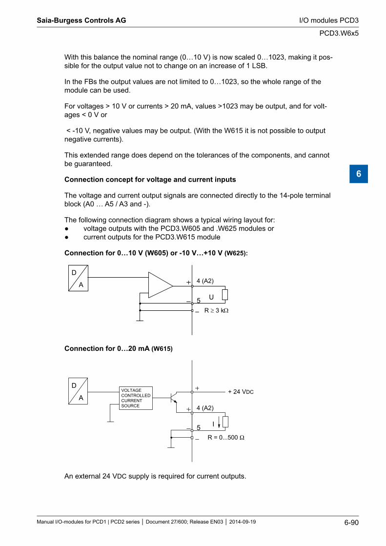
With this balance the nominal range (0…10 V) is now scaled 0…1023, making it pos-sible for the output value not to change on an increase of 1 LSB.
In the FBs the output values are not limited to 0…1023, so the whole range of the module can be used.
For voltages > 10 V or currents > 20 mA, values >1023 may be output, and for volt-ages < 0 V or
< -10 V, negative values may be output. (With the W615 it is not possible to output negative currents).
This extended range does depend on the tolerances of the components, and cannot be guaranteed.
Connection concept for voltage and current inputs
The voltage and current output signals are connected directly to the 14-pole terminal block (A0 … A5 / A3 and -).
The following connection diagram shows a typical wiring layout for: voltage outputs with the PCD3.W605 and .W625 modules or current outputs for the PCD3.W615 module
Connection for 0…10 V (W605) or -10 V…+10 V (W625):
4 (A2)D
A
5 U
R ≥ 3 kΩ
Connection for 0…20 mA (W615)
4 (A2)
5 I
R = 0...500 Ω
D
AVOLTAGECONTROLLEDCURRENTSOURCE
+ 24 VDC
An external 24 VDC supply is required for current outputs.
Saia-Burgess Controls AG
Manual I/O-modules for PCD1 | PCD2 series Document 27/600; Release EN03 2014-09-19 6-90
I/O modules PCD3
PCD3.W6x5
6
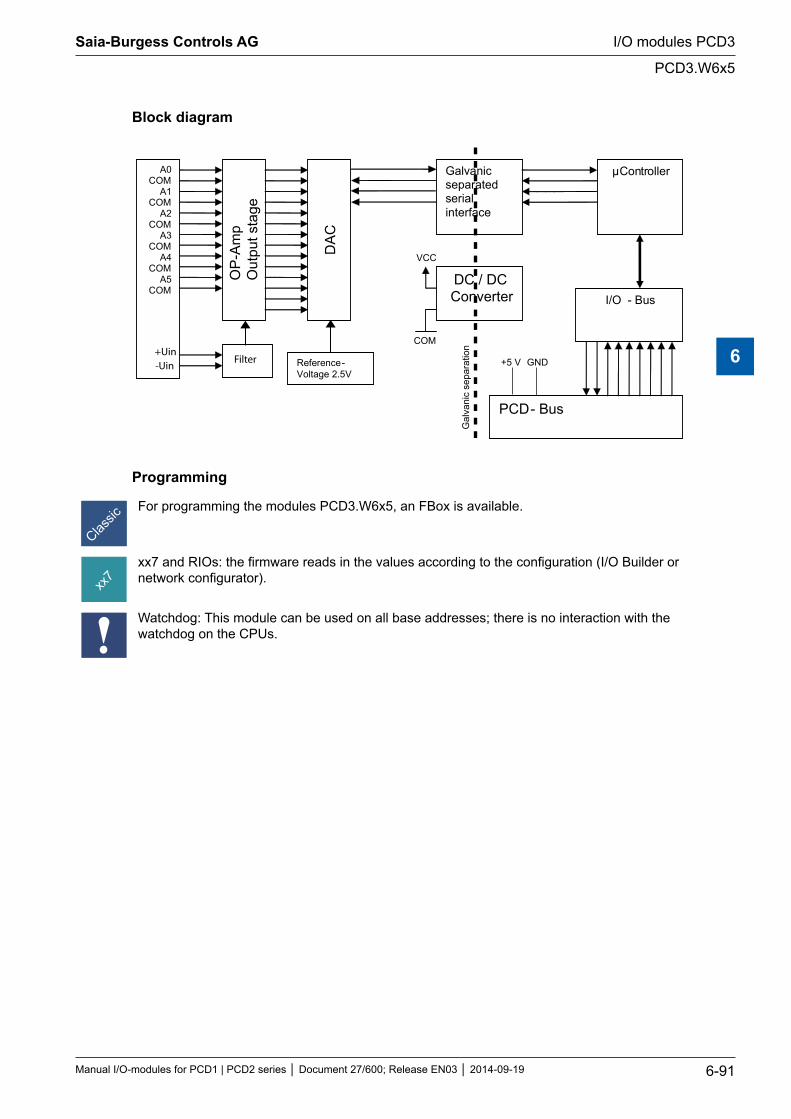
Block diagram
OP
-Am
p O
utpu
t sta
ge
A0 COM
A1 COM
A2 COM
A3 COM
A4 COM
A5 COM
DA
C
Ref erence - Voltage 2.5V
μController
PCD - Bus
I/O - Bus DC / DC Converter
Galvanic separated s erial interface
Gal
vani
c se
para
tion
VCC
COM
+5 V GND Filter +Uin -Uin
Programming
For programming the modules PCD3.W6x5, an FBox is available.
xx7 and RIOs: the firmware reads in the values according to the configuration (I/O Builder or network configurator).
Watchdog: This module can be used on all base addresses; there is no interaction with the watchdog on the CPUs.
Saia-Burgess Controls AG
Manual I/O-modules for PCD1 | PCD2 series Document 27/600; Release EN03 2014-09-19 6-91
I/O modules PCD3
PCD3.W6x5
6
6.12 Analogue combined input/output modules
PCD3.W500 2 analogue inputs 12 bit + 2 analogue outputs 12 bit, 0…10 V, -10 V…+10 V *)
*) jumper selectable
I/O modules and I/O terminal blocks may only be plugged in and removed when the Saia PCD® and the external +24?V are disconnected from the power supply.
Saia-Burgess Controls AG
Manual I/O-modules for PCD1 | PCD2 series Document 27/600; Release EN03 2014-09-19 6-92
I/O modules PCD3
Analogue combined input/output modules
6
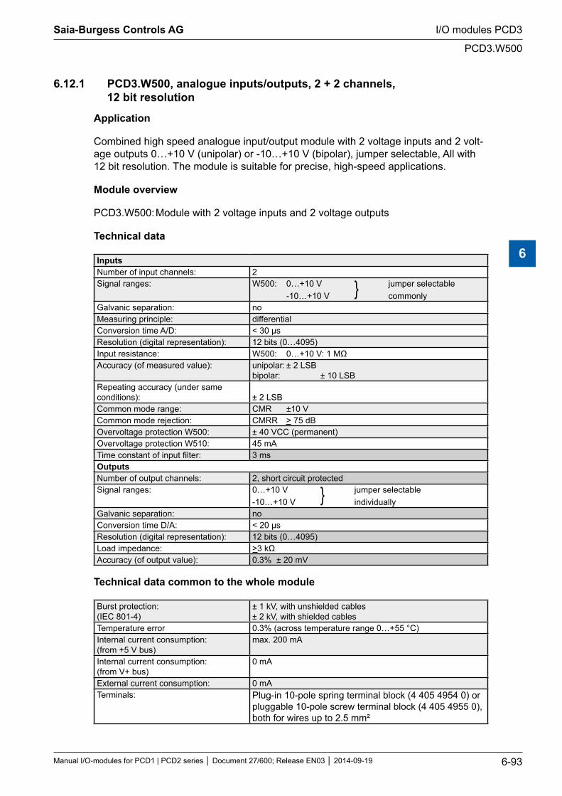
6.12.1 PCD3.W500, analogue inputs/outputs, 2 + 2 channels, 12 bit resolution
Application
Combined high speed analogue input/output module with 2 voltage inputs and 2 volt-age outputs 0…+10 V (unipolar) or -10…+10 V (bipolar), jumper selectable, All with 12 bit resolution. The module is suitable for precise, high-speed applications.
Module overview
PCD3.W500: Module with 2 voltage inputs and 2 voltage outputs
Technical data
InputsNumber of input channels: 2Signal ranges: W500: 0…+10 V jumper selectable
-10…+10 V commonlyGalvanic separation: noMeasuring principle: differentialConversion time A/D: < 30 µsResolution (digital representation): 12 bits (0…4095)Input resistance: W500: 0…+10 V: 1 MΩAccuracy (of measured value): unipolar: ± 2 LSB
bipolar: ± 10 LSBRepeating accuracy (under same conditions):
± 2 LSB
Common mode range: CMR ±10 VCommon mode rejection: CMRR > 75 dBOvervoltage protection W500: ± 40 VCC (permanent)Overvoltage protection W510: 45 mATime constant of input filter: 3 msOutputsNumber of output channels: 2, short circuit protectedSignal ranges: 0…+10 V jumper selectable
-10…+10 V individuallyGalvanic separation: noConversion time D/A: < 20 µsResolution (digital representation): 12 bits (0…4095)Load impedance: >3 kΩAccuracy (of output value): 0.3% ± 20 mV
Technical data common to the whole module
Burst protection: (IEC 801-4)
± 1 kV, with unshielded cables ± 2 kV, with shielded cables
Temperature error 0.3% (across temperature range 0…+55 °C)Internal current consumption: (from +5 V bus)
max. 200 mA
Internal current consumption: (from V+ bus)
0 mA
External current consumption: 0 mATerminals: Plug-in 10-pole spring terminal block (4 405 4954 0) or
pluggable 10-pole screw terminal block (4 405 4955 0), both for wires up to 2.5 mm²
Saia-Burgess Controls AG
Manual I/O-modules for PCD1 | PCD2 series Document 27/600; Release EN03 2014-09-19 6-93
I/O modules PCD3
PCD3.W500
6
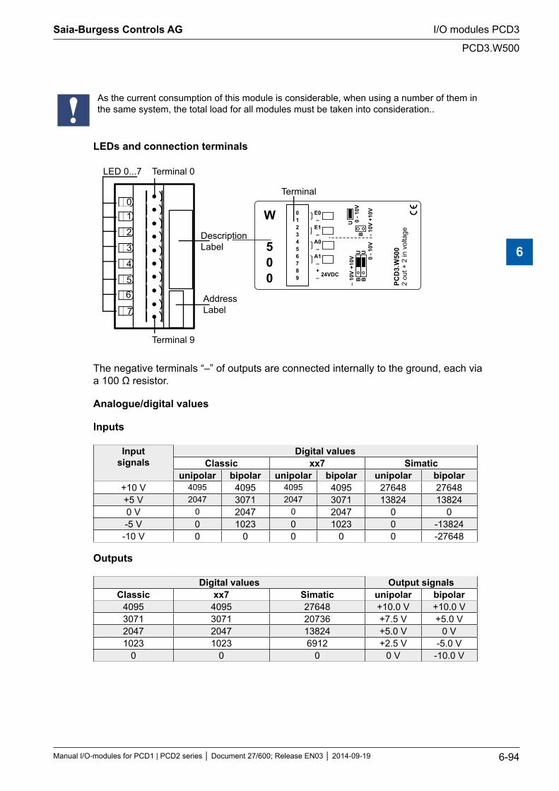
As the current consumption of this module is considerable, when using a number of them in the same system, the total load for all modules must be taken into consideration..
LEDs and connection terminals
01
2
3
4
56
7
LED 0...7 Terminal 0
DescriptionLabel
AddressLabel
- 10V
+10
V
0 - 1
0VU
B–
10
V+1
0V 0 - 1
0V
BU
BU
0123456789
E0–
E1–
A0–
A1–+– 24VDC
PCD
3.W
500
2 ou
t + 2
in v
olta
ge
Terminal 9
Terminal
W
500
The negative terminals “–” of outputs are connected internally to the ground, each via a 100 Ω resistor.
Analogue/digital values
Inputs
Input signals
Digital values Classic xx7 Simatic
unipolar bipolar unipolar bipolar unipolar bipolar+10 V 4095 4095 4095 4095 27648 27648+5 V 2047 3071 2047 3071 13824 138240 V 0 2047 0 2047 0 0-5 V 0 1023 0 1023 0 -13824
-10 V 0 0 0 0 0 -27648
Outputs
Digital values Output signalsClassic xx7 Simatic unipolar bipolar
4095 4095 27648 +10.0 V +10.0 V3071 3071 20736 +7.5 V +5.0 V2047 2047 13824 +5.0 V 0 V1023 1023 6912 +2.5 V -5.0 V
0 0 0 0 V -10.0 V
Saia-Burgess Controls AG
Manual I/O-modules for PCD1 | PCD2 series Document 27/600; Release EN03 2014-09-19 6-94
I/O modules PCD3
PCD3.W500
6
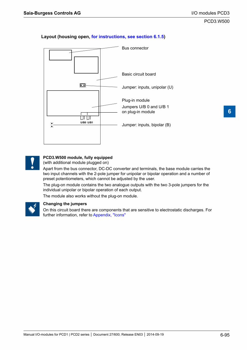
Layout (housing open, for instructions, see section 6.1.5)
U/B0 U/B1
Bus connector
Basic circuit board
Jumper: inputs, unipolar (U)
Plug-in moduleJumpers U/B 0 and U/B 1 on plug-in module
Jumper: inputs, bipolar (B)
PCD3.W500 module, fully equipped (with additional module plugged on)Apart from the bus connector, DC-DC converter and terminals, the base module carries the two input channels with the 2-pole jumper for unipolar or bipolar operation and a number of preset potentiometers, which cannot be adjusted by the user.The plug-on module contains the two analogue outputs with the two 3-pole jumpers for the individual unipolar or bipolar operation of each output.The module also works without the plug-on module.
Changing the jumpersOn this circuit board there are components that are sensitive to electrostatic discharges. For further information, refer to Appendix, "Icons"
Saia-Burgess Controls AG
Manual I/O-modules for PCD1 | PCD2 series Document 27/600; Release EN03 2014-09-19 6-95
I/O modules PCD3
PCD3.W500
6
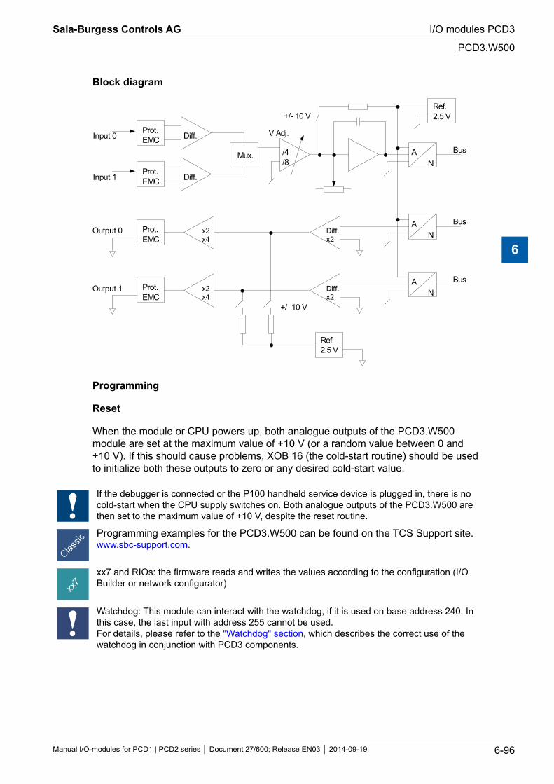
Block diagram
Prot.EMC Diff.
Mux.
Prot.EMC Diff.
Input 0
Input 1
/4/8
V Adj.
AN
Bus
Ref.2.5 V+/- 10 V
AN
BusDiff.x2
Prot.EMC
x2x4
AN
BusDiff.x2
Prot.EMC
x2x4
Output 0
Output 1
Ref.2.5 V
+/- 10 V
Programming
Reset
When the module or CPU powers up, both analogue outputs of the PCD3.W500 module are set at the maximum value of +10 V (or a random value between 0 and +10 V). If this should cause problems, XOB 16 (the cold-start routine) should be used to initialize both these outputs to zero or any desired cold-start value.
If the debugger is connected or the P100 handheld service device is plugged in, there is no cold-start when the CPU supply switches on. Both analogue outputs of the PCD3.W500 are then set to the maximum value of +10 V, despite the reset routine.
Programming examples for the PCD3.W500 can be found on the TCS Support site.www.sbc-support.com.
xx7 and RIOs: the firmware reads and writes the values according to the configuration (I/O Builder or network configurator)
Watchdog: This module can interact with the watchdog, if it is used on base address 240. In this case, the last input with address 255 cannot be used. For details, please refer to the "Watchdog" section, which describes the correct use of the watchdog in conjunction with PCD3 components.
Saia-Burgess Controls AG
Manual I/O-modules for PCD1 | PCD2 series Document 27/600; Release EN03 2014-09-19 6-96
I/O modules PCD3
PCD3.W500
6
6.13 Analogue combined input/output modules, electrically isolated
PCD3.W525 4 inputs, 14 Bit, 0…10 V, 0(4)…20 mA, Pt1000, Pt500 or Ni1000 (selectable via DIP switch)
and
2 outputs, 12 Bit, 0…10 V or 0(4)…20 mA (selectable via software (FBox, FB)
Galvanic separation of outputs to Saia PCD®, channels themselves not separated
I/O modules and I/O terminal blocks may only be plugged in and removed when the Saia PCD® and the external +24?V are disconnected from the power supply.
Saia-Burgess Controls AG
Manual I/O-modules for PCD1 | PCD2 series Document 27/600; Release EN03 2014-09-19 6-97
I/O modules PCD3
Analogue combined input/output modules, electrically isolated
6
6.13.1 PCD3.W525 analogue combined input/output module with electrical isolation
General information
The PCD3.W525 is an analogue multi-purpose module with four inputs and four outputs. Each input and output can be configured individually as an industry-standard interface of type 0 … 10 V, 0 … 20 mA und 4 … 20 mA. The inputs can also be configured in such a way that they can support Pt/Ni1000 or Pt500 temperature sensors. Various filter types and scaling ranges can also be used for the module.
Inputs, 14 Bit
4 inputs. Each channel has four operating modes (configurable with DIP switches)
Differential voltage inputs 0 … 10 V, resolution: 0.61 mV per LSB (14 Bit)
Differential current inputs - measured in differential mode 0 … 20 mA, resolution: 1.2 μA per LSB (14 Bit) 4 … 20 mA, resolution: 1.2 μA per LSB (13.7 Bit)
Temperature Pt1000, -50 … 400 °C, resolution: 0.1 °C Pt500, -50 … 400 °C, resolution: 0.2 °C Ni1000, -60 … 200 °C, resolution 0.1 °C
Resistance 0 … 2500 Ω, resolution 0.2 Ω
Each channel can be configured to have a software-based filter with 50 Hz/ 60 Hz
Outputs, 12 Bit
2 outputs. Each channel has three operating modes (configurable via software)
Voltage 0 … 10 V, resolution: 2.44 mV per LSB (12 Bit)
Current 0 … 20 mA, resolution: 4.88 μA per LSB (12 Bit) 4 … 20 mA, resolution: 4.88 μA per LSB (11.7 Bit)
High impedance:
Miscellaneous
All I/O channels are electrically isolated from the Saia PCD® and the external power supply. (but all channels are electrically connected to each other).
Each channel has two connections.
Saia-Burgess Controls AG
Manual I/O-modules for PCD1 | PCD2 series Document 27/600; Release EN03 2014-09-19 6-98
I/O modules PCD3
PCD3.W525
6
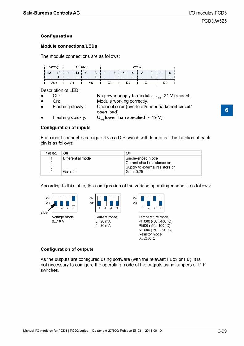
Configuration
Module connections/LEDs
The module connections are as follows:
Description of LED: Off: No power supply to module. Uext (24 V) absent. On: Module working correctly. Flashing slowly: Channel error (overload/underload/short circuit/ open load) Flashing quickly: Uext lower than specified (< 19 V).
Configuration of inputs
Each input channel is configured via a DIP switch with four pins. The function of each pin is as follows:
Pin no. Off On1 2 3 4
Differential mode Gain=1
Single-ended mode Current shunt resistance on Supply to external resistors on Gain=0,25
According to this table, the configuration of the various operating modes is as follows:
Voltage mode0...10 V
Current mode0...20 mA4...20 mA
Temperature modePt1000 (-50...400 ˚C)Pt500 (-50...400 ˚C)Ni1000 (-60...200 ˚C)Resistor mode0...2500 Ω
1 2 3 4
OnOff
1 2 3 4
OnOff
1 2 3 4
OnOff
slider
Configuration of outputs
As the outputs are configured using software (with the relevant FBox or FB), it is not necessary to configure the operating mode of the outputs using jumpers or DIP switches.
Saia-Burgess Controls AG
Manual I/O-modules for PCD1 | PCD2 series Document 27/600; Release EN03 2014-09-19 6-99
I/O modules PCD3
PCD3.W525
6
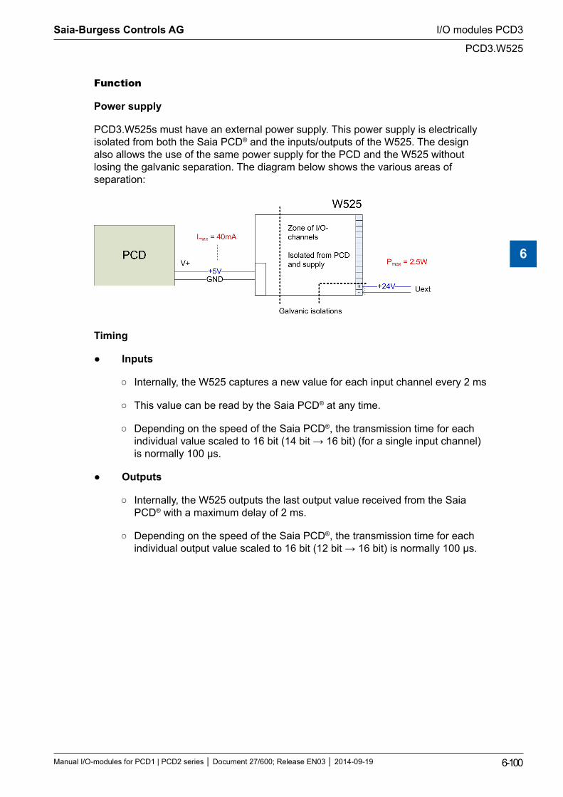
Function
Power supply
PCD3.W525s must have an external power supply. This power supply is electrically isolated from both the Saia PCD® and the inputs/outputs of the W525. The design also allows the use of the same power supply for the PCD and the W525 without losing the galvanic separation. The diagram below shows the various areas of separation:
Timing
Inputs
Internally, the W525 captures a new value for each input channel every 2 ms
This value can be read by the Saia PCD® at any time.
Depending on the speed of the Saia PCD®, the transmission time for each individual value scaled to 16 bit (14 bit → 16 bit) (for a single input channel) is normally 100 μs.
Outputs
Internally, the W525 outputs the last output value received from the Saia PCD® with a maximum delay of 2 ms.
Depending on the speed of the Saia PCD®, the transmission time for each individual output value scaled to 16 bit (12 bit → 16 bit) is normally 100 μs.
Saia-Burgess Controls AG
Manual I/O-modules for PCD1 | PCD2 series Document 27/600; Release EN03 2014-09-19 6-100
I/O modules PCD3
PCD3.W525
6
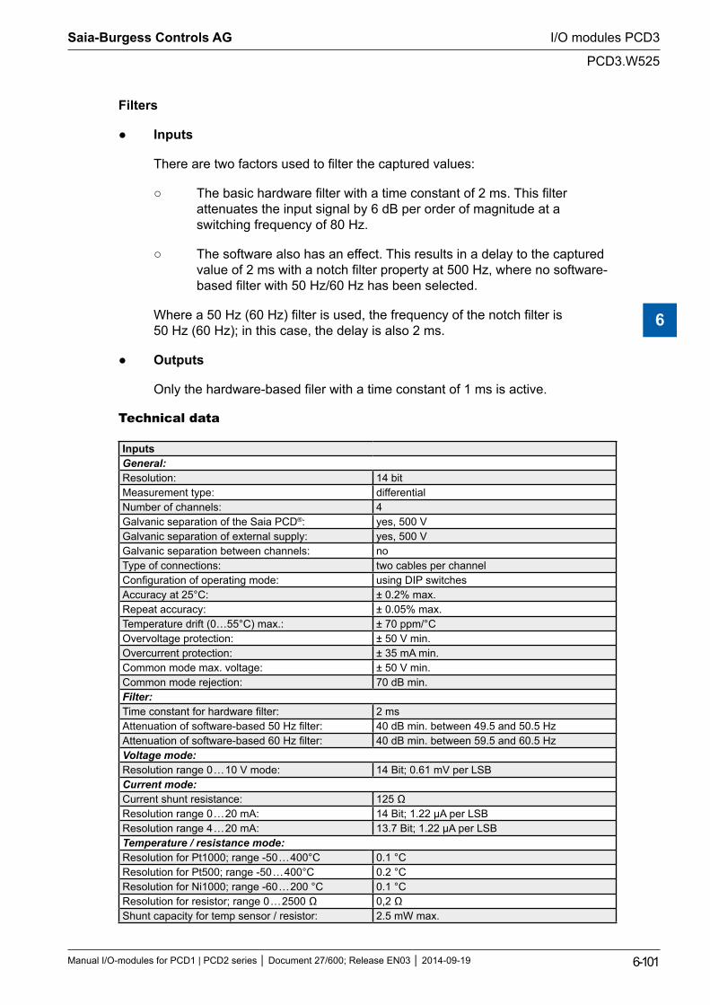
Filters
Inputs
There are two factors used to filter the captured values:
The basic hardware filter with a time constant of 2 ms. This filter attenuates the input signal by 6 dB per order of magnitude at a switching frequency of 80 Hz.
The software also has an effect. This results in a delay to the captured value of 2 ms with a notch filter property at 500 Hz, where no software-based filter with 50 Hz/60 Hz has been selected.
Where a 50 Hz (60 Hz) filter is used, the frequency of the notch filter is 50 Hz (60 Hz); in this case, the delay is also 2 ms.
Outputs
Only the hardware-based filer with a time constant of 1 ms is active.
Technical data
InputsGeneral:Resolution: 14 bitMeasurement type: differential Number of channels: 4Galvanic separation of the Saia PCD®: yes, 500 VGalvanic separation of external supply: yes, 500 VGalvanic separation between channels: noType of connections: two cables per channelConfiguration of operating mode: using DIP switchesAccuracy at 25°C: ± 0.2% max.Repeat accuracy: ± 0.05% max.Temperature drift (0…55°C) max.: ± 70 ppm/°COvervoltage protection: ± 50 V min.Overcurrent protection: ± 35 mA min.Common mode max. voltage: ± 50 V min.Common mode rejection: 70 dB min.Filter:Time constant for hardware filter: 2 msAttenuation of software-based 50 Hz filter: 40 dB min. between 49.5 and 50.5 HzAttenuation of software-based 60 Hz filter: 40 dB min. between 59.5 and 60.5 HzVoltage mode:Resolution range 0 … 10 V mode: 14 Bit; 0.61 mV per LSBCurrent mode:Current shunt resistance: 125 ΩResolution range 0 … 20 mA: 14 Bit; 1.22 µA per LSBResolution range 4 … 20 mA: 13.7 Bit; 1.22 µA per LSBTemperature / resistance mode:Resolution for Pt1000; range -50 … 400°C 0.1 °CResolution for Pt500; range -50 … 400°C 0.2 °CResolution for Ni1000; range -60 … 200 °C 0.1 °CResolution for resistor; range 0 … 2500 Ω 0,2 ΩShunt capacity for temp sensor / resistor: 2.5 mW max.
Saia-Burgess Controls AG
Manual I/O-modules for PCD1 | PCD2 series Document 27/600; Release EN03 2014-09-19 6-101
I/O modules PCD3
PCD3.W525
6
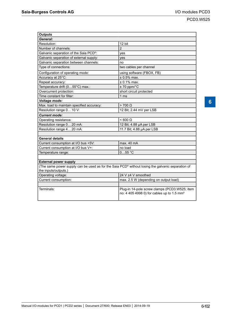
OutputsGeneral:Resolution: 12 bitNumber of channels: 2Galvanic separation of the Saia PCD®: yesGalvanic separation of external supply: yesGalvanic separation between channels: noType of connections: two cables per channel
Configuration of operating mode: using software (FBOX, FB)Accuracy at 25°C: ± 0.5% max.Repeat accuracy: ± 0.1% max.Temperature drift (0…55°C) max.: ± 70 ppm/°COvercurrent protection: short circuit protectedTime constant for filter: 1 msVoltage mode:Max. load to maintain specified accuracy: > 700 ΩResolution range 0 … 10 V: 12 Bit; 2.44 mV per LSBCurrent mode:Operating resistance: < 600 ΩResolution range 0 … 20 mA: 12 Bit; 4.88 µA per LSBResolution range 4 … 20 mA: 11.7 Bit; 4.88 µA per LSB
General detailsCurrent consumption at I/O bus +5V: max. 40 mACurrent consumption at I/O bus V+: no loadTemperature range: 0…55 °C
External power supply(The same power supply can be used as for the Saia PCD® without losing the galvanic separation of the inputs/outputs.)Operating voltage: 24 V ±4 V smoothed Current consumption: max. 2.5 W (depending on output load)
Terminals: Plug-in 14-pole screw clamps (PCD3.W525; item no: 4 405 4998 0) for cables up to 1.5 mm²
Saia-Burgess Controls AG
Manual I/O-modules for PCD1 | PCD2 series Document 27/600; Release EN03 2014-09-19 6-102
I/O modules PCD3
PCD3.W525
6
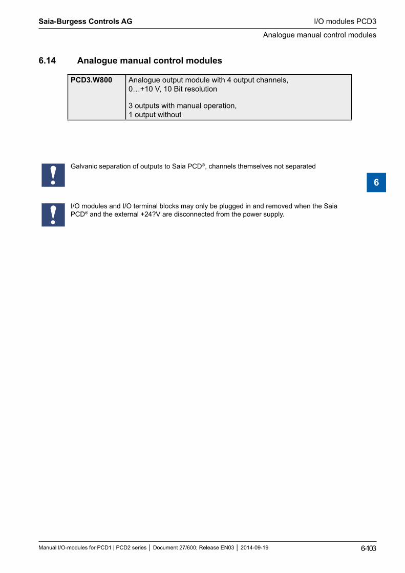
6.14 Analogue manual control modules
PCD3.W800 Analogue output module with 4 output channels, 0…+10 V, 10 Bit resolution
3 outputs with manual operation, 1 output without
Galvanic separation of outputs to Saia PCD®, channels themselves not separated
I/O modules and I/O terminal blocks may only be plugged in and removed when the Saia PCD® and the external +24?V are disconnected from the power supply.
Saia-Burgess Controls AG
Manual I/O-modules for PCD1 | PCD2 series Document 27/600; Release EN03 2014-09-19 6-103
I/O modules PCD3
Analogue manual control modules
6
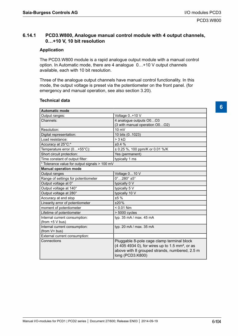
6.14.1 PCD3.W800, Analogue manual control module with 4 output channels, 0…+10 V, 10 bit resolution
Application
The PCD3.W800 module is a rapid analogue output module with a manual control option. In Automatic mode, there are 4 analogue 0…+10 V output channels available, each with 10 bit resolution.
Three of the analogue output channels have manual control functionality. In this mode, the output voltage is preset via the potentiometer on the front panel. (for emergency and manual operation, see also section 3.20).
Technical data
Automatic modeOutput ranges: Voltage 0..+10 VChannels: 4 analogue outputs O0…O3
(3 with manual operation O0…O2)Resolution: 10 mVDigital representation: 10 bits (0..1023)Load resistance: > 3 kΩAccuracy at 25°C:* ±0.4 %Temperature error (0…+55°C): ± 0.25 %, 100 ppm/K or 0.01 %/KShort circuit protection: Yes (permanent)Time constant of output filter: typically 1 ms* Tolerance value for output signals > 100 mVManual operation modeOutput ranges Voltage 0…10 VRange of settings for potentiometer 0°…280° ±5°Output voltage at 0° typically 0 VOutput voltage at 140° typically 5 VOutput voltage at 280° typically 10 VAccuracy at end stop ±5 %Linearity error of potentiometer ±20 %moment of potentiometer < 0.01 NmLifetime of potentiometer > 5000 cyclesInternal current consumption: (from +5 V bus)
typ. 35 mA / max. 45 mA
Internal current consumption: (from V+ bus)
typ. 20 mA / max. 35 mA
External current consumption:Connections Pluggable 8-pole cage clamp terminal block
(4 405 4934 0), for wires up to 1.5 mm², or as above with 8 grouped strands, numbered, 2.5 m long (PCD3.K800)
Saia-Burgess Controls AG
Manual I/O-modules for PCD1 | PCD2 series Document 27/600; Release EN03 2014-09-19 6-104
I/O modules PCD3
PCD3.W800
6
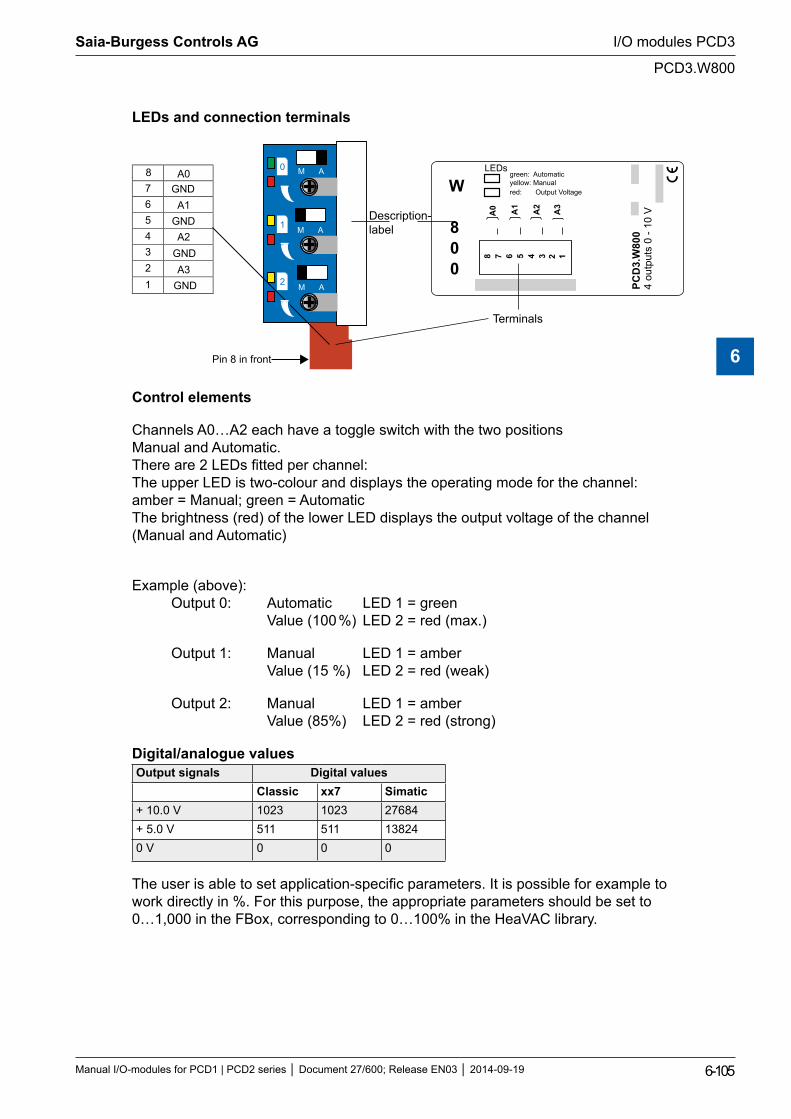
LEDs and connection terminals
M A
M A
GNDA0
765
A1
43
A2
21
A3
Pin 8 in front
PCD
3.W
800
4 ou
tput
s 0
- 10
V
W
800
8 7 6 5 4 3
A0 A1
A2
A3
2 1
LEDsgreen: Automaticyellow: Manual red: Output Voltage
Description-label
Terminals
GND
GND
GND
8
M A
0
1
2
Control elements
Channels A0…A2 each have a toggle switch with the two positions Manual and Automatic. There are 2 LEDs fitted per channel: The upper LED is two-colour and displays the operating mode for the channel: amber = Manual; green = Automatic The brightness (red) of the lower LED displays the output voltage of the channel (Manual and Automatic)
Example (above): Output 0: Automatic LED 1 = green Value (100 %) LED 2 = red (max.)
Output 1: Manual LED 1 = amber Value (15 %) LED 2 = red (weak)
Output 2: Manual LED 1 = amber Value (85%) LED 2 = red (strong)
Digital/analogue valuesOutput signals Digital values
Classic xx7 Simatic+ 10.0 V 1023 1023 27684+ 5.0 V 511 511 138240 V 0 0 0
The user is able to set application-specific parameters. It is possible for example to work directly in %. For this purpose, the appropriate parameters should be set to 0…1,000 in the FBox, corresponding to 0…100% in the HeaVAC library.
Saia-Burgess Controls AG
Manual I/O-modules for PCD1 | PCD2 series Document 27/600; Release EN03 2014-09-19 6-105
I/O modules PCD3
PCD3.W800
6
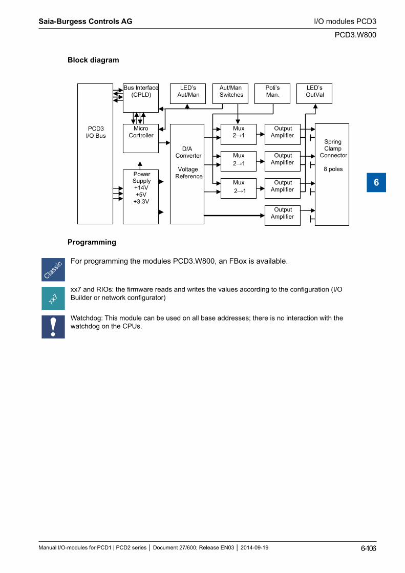
Block diagram
PCD3 I/O Bus
Bus Interface (CPLD)
Micro Controller
Aut/Man Switches
LED’s Aut/Man
Poti’s Man.
LED’s OutVal
D/A Converter
Voltage
Reference
Mux 2→1
Mux
Mux
Output Amplifier
Output Amplifier
Output Amplifier
Output Amplifier
Power Supply +14V +5V
+3.3V
Spring Clamp
Connector
8 poles
2→1
2→1
Programming
For programming the modules PCD3.W800, an FBox is available.
xx7 and RIOs: the firmware reads and writes the values according to the configuration (I/O Builder or network configurator)
Watchdog: This module can be used on all base addresses; there is no interaction with the watchdog on the CPUs.
Saia-Burgess Controls AG
Manual I/O-modules for PCD1 | PCD2 series Document 27/600; Release EN03 2014-09-19 6-106
I/O modules PCD3
PCD3.W800
6
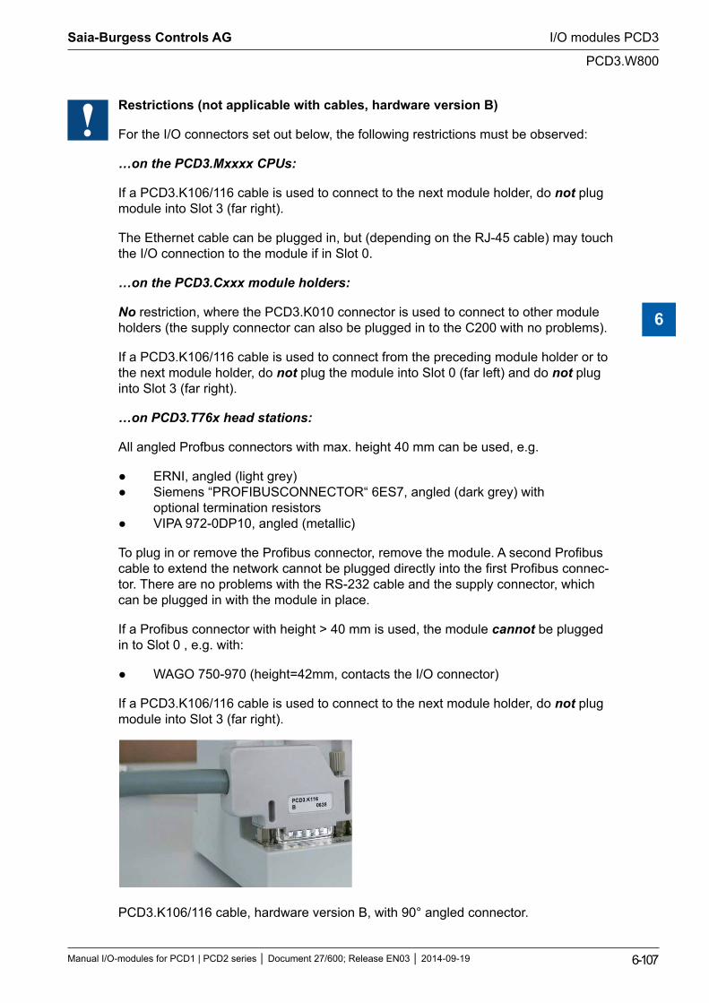
Restrictions (not applicable with cables, hardware version B)
For the I/O connectors set out below, the following restrictions must be observed:
…on the PCD3.Mxxxx CPUs:
If a PCD3.K106/116 cable is used to connect to the next module holder, do not plug module into Slot 3 (far right).
The Ethernet cable can be plugged in, but (depending on the RJ-45 cable) may touch the I/O connection to the module if in Slot 0.
…on the PCD3.Cxxx module holders:
No restriction, where the PCD3.K010 connector is used to connect to other module holders (the supply connector can also be plugged in to the C200 with no problems).
If a PCD3.K106/116 cable is used to connect from the preceding module holder or to the next module holder, do not plug the module into Slot 0 (far left) and do not plug into Slot 3 (far right).
…on PCD3.T76x head stations:
All angled Profbus connectors with max. height 40 mm can be used, e.g.
ERNI, angled (light grey) Siemens “PROFIBUSCONNECTOR“ 6ES7, angled (dark grey) with optional termination resistors VIPA 972-0DP10, angled (metallic)
To plug in or remove the Profibus connector, remove the module. A second Profibus cable to extend the network cannot be plugged directly into the first Profibus connec-tor. There are no problems with the RS-232 cable and the supply connector, which can be plugged in with the module in place.
If a Profibus connector with height > 40 mm is used, the module cannot be plugged in to Slot 0 , e.g. with:
WAGO 750-970 (height=42mm, contacts the I/O connector)
If a PCD3.K106/116 cable is used to connect to the next module holder, do not plug module into Slot 3 (far right).
PCD3.K106/116 cable, hardware version B, with 90° angled connector.
Saia-Burgess Controls AG
Manual I/O-modules for PCD1 | PCD2 series Document 27/600; Release EN03 2014-09-19 6-107
I/O modules PCD3
PCD3.W800
6
6.15 Weighing modules
PCD3.W720 2-channel weighing module for 4/6-wire weighing cells
¹) These I/O modules cannot currently be used with the PCD3 RIO head station
I/O modules and I/O terminal blocks may only be plugged in and removed when the Saia PCD® and the external +24?V are disconnected from the power supply.
6.15.1 PCD3.W720
The PCD3.W720 module is described in Manual 26/833.
Saia-Burgess Controls AG
Manual I/O-modules for PCD1 | PCD2 series Document 27/600; Release EN03 2014-09-19 6-108
I/O modules PCD3
PCD3.W720
6
6.16 General-purpose temperature modules
PCD3.W745 Thermocouple modules, 4-channel
Supported temperature sensors are:
Thermocouples – TC type J,K
Resistance thermometer (RTD) – RTD type Pt 100, Pt 1000, Ni 100, Ni1000
I/O modules and I/O terminal blocks may only be plugged in and removed when the Saia PCD® and the external +24?V are disconnected from the power supply.
6.16.1 PCD3.W745
The PCD3.W745 module is described in Manual 26/796.
Saia-Burgess Controls AG
Manual I/O-modules for PCD1 | PCD2 series Document 27/600; Release EN03 2014-09-19 6-109
I/O modules PCD3
PCD3.W745
6
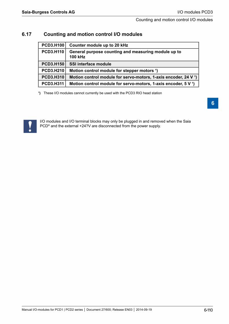
6.17 Counting and motion control I/O modules
PCD3.H100 Counter module up to 20 kHzPCD3.H110 General purpose counting and measuring module up to
100 kHzPCD3.H150 SSI interface modulePCD3.H210 Motion control module for stepper motors ¹)PCD3.H310 Motion control module for servo-motors, 1-axis encoder, 24 V ¹)PCD3.H311 Motion control module for servo-motors, 1-axis encoder, 5 V ¹)
¹) These I/O modules cannot currently be used with the PCD3 RIO head station
I/O modules and I/O terminal blocks may only be plugged in and removed when the Saia PCD® and the external +24?V are disconnected from the power supply.
Saia-Burgess Controls AG
Manual I/O-modules for PCD1 | PCD2 series Document 27/600; Release EN03 2014-09-19 6-110
I/O modules PCD3
Counting and motion control I/O modules
6
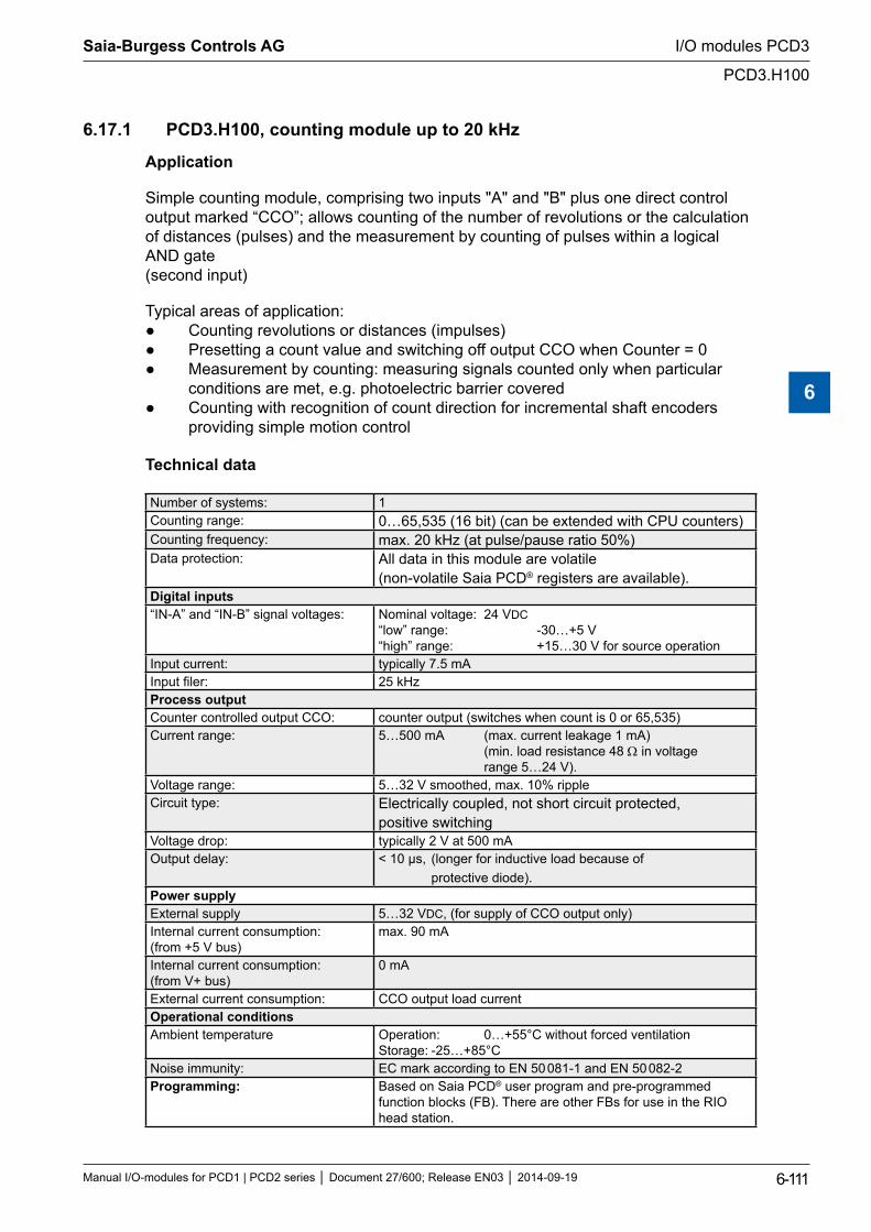
6.17.1 PCD3.H100, counting module up to 20 kHz
Application
Simple counting module, comprising two inputs "A" and "B" plus one direct control output marked “CCO”; allows counting of the number of revolutions or the calculation of distances (pulses) and the measurement by counting of pulses within a logical AND gate (second input)
Typical areas of application: Counting revolutions or distances (impulses) Presetting a count value and switching off output CCO when Counter = 0 Measurement by counting: measuring signals counted only when particular conditions are met, e.g. photoelectric barrier covered Counting with recognition of count direction for incremental shaft encoders providing simple motion control
Technical data
Number of systems: 1Counting range: 0…65,535 (16 bit) (can be extended with CPU counters)Counting frequency: max. 20 kHz (at pulse/pause ratio 50%)Data protection: All data in this module are volatile
(non-volatile Saia PCD® registers are available).Digital inputs“IN-A” and “IN-B” signal voltages: Nominal voltage: 24 VDC
“low” range: -30…+5 V “high” range: +15…30 V for source operation
Input current: typically 7.5 mAInput filer: 25 kHzProcess outputCounter controlled output CCO: counter output (switches when count is 0 or 65,535)Current range: 5…500 mA (max. current leakage 1 mA)
(min. load resistance 48 Ω in voltage range 5…24 V).
Voltage range: 5…32 V smoothed, max. 10% ripple Circuit type: Electrically coupled, not short circuit protected,
positive switchingVoltage drop: typically 2 V at 500 mAOutput delay: < 10 µs, (longer for inductive load because of
protective diode).Power supplyExternal supply 5…32 VDC, (for supply of CCO output only)Internal current consumption: (from +5 V bus)
max. 90 mA
Internal current consumption: (from V+ bus)
0 mA
External current consumption: CCO output load currentOperational conditionsAmbient temperature Operation: 0…+55°C without forced ventilation
Storage: -25…+85°CNoise immunity: EC mark according to EN 50 081-1 and EN 50 082-2Programming: Based on Saia PCD® user program and pre-programmed
function blocks (FB). There are other FBs for use in the RIO head station.
Saia-Burgess Controls AG
Manual I/O-modules for PCD1 | PCD2 series Document 27/600; Release EN03 2014-09-19 6-111
I/O modules PCD3
PCD3.H100
6
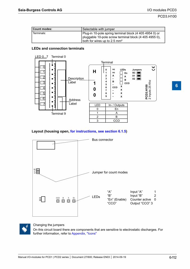
Count modes: Selectable with jumperTerminals: Plug-in 10-pole spring terminal block (4 405 4954 0) or
pluggable 10-pole screw terminal block (4 405 4955 0), both for wires up to 2.5 mm²
LEDs and connection terminals
01
2
3
4
56
7
LED 0...7 Terminal 0
DescriptionLabel
AddressLabel
A–B–CCO–+–
PCD
3.H
100
2 In
puts
25
Khz
0123456789
LEDs En
A B CCO
JumpersSCX1X2
Terminal 9
Terminal
ncncH
100
LED In- / Outputs0 En1 A2 B3 CCO
Layout (housing open, for instructions, see section 6.1.5)
CCO B A En
SCx1x2
Bus connector
Jumper for count modes
LEDs “A” Input “A” 1 “B” Input “B” 2 “En” (Enable) Counter active 0 “CCO” Output “CCO” 3
Changing the jumpersOn this circuit board there are components that are sensitive to electrostatic discharges. For further information, refer to Appendix, "Icons"
Saia-Burgess Controls AG
Manual I/O-modules for PCD1 | PCD2 series Document 27/600; Release EN03 2014-09-19 6-112
I/O modules PCD3
PCD3.H100
6
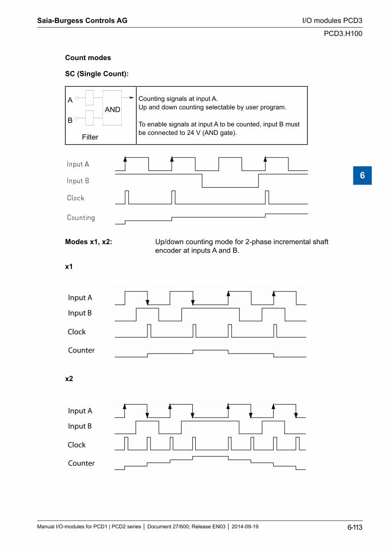
Count modes
SC (Single Count):
ANDA
B
Filter
Counting signals at input A.Up and down counting selectable by user program.
To enable signals at input A to be counted, input B must be connected to 24 V (AND gate).
Modes x1, x2: Up/down counting mode for 2-phase incremental shaft encoder at inputs A and B.
x1
Input A
Input B
Clock
Counter
x2
Input A
Input B
Clock
Counter
Saia-Burgess Controls AG
Manual I/O-modules for PCD1 | PCD2 series Document 27/600; Release EN03 2014-09-19 6-113
I/O modules PCD3
PCD3.H100
6
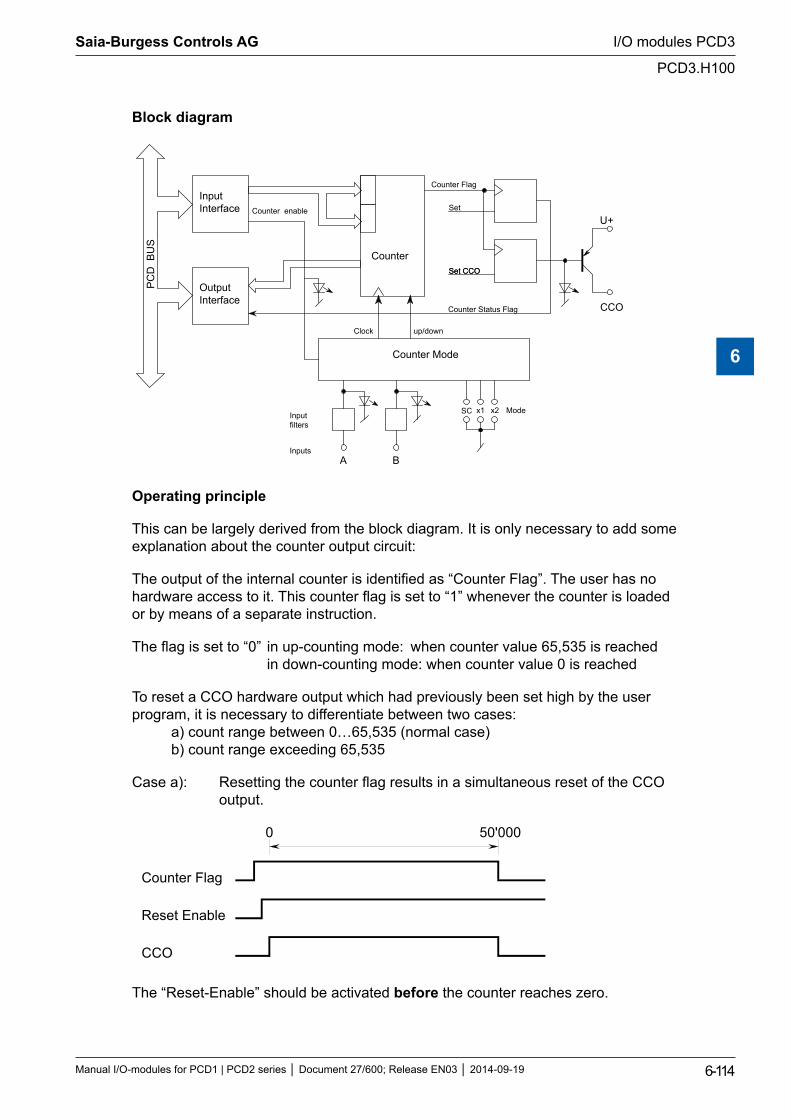
Block diagram
A B
SC x1 x2
CCO
U+
Input Interface
Output Interface
Counter Flag
Counter enable
Counter Mode
up/down Clock
Set CCO
PC
D B
US
Input filters
Inputs
Mode
Counter Status Flag
Counter
Set
Set CCO
Operating principle
This can be largely derived from the block diagram. It is only necessary to add some explanation about the counter output circuit:
The output of the internal counter is identified as “Counter Flag”. The user has no hardware access to it. This counter flag is set to “1” whenever the counter is loaded or by means of a separate instruction.
The flag is set to “0” in up-counting mode: when counter value 65,535 is reached in down-counting mode: when counter value 0 is reached
To reset a CCO hardware output which had previously been set high by the user program, it is necessary to differentiate between two cases: a) count range between 0…65,535 (normal case) b) count range exceeding 65,535
Case a): Resetting the counter flag results in a simultaneous reset of the CCO output.
Counter Flag
Reset Enable
CCO
0 50'000
The “Reset-Enable” should be activated before the counter reaches zero.
Saia-Burgess Controls AG
Manual I/O-modules for PCD1 | PCD2 series Document 27/600; Release EN03 2014-09-19 6-114
I/O modules PCD3
PCD3.H100
6
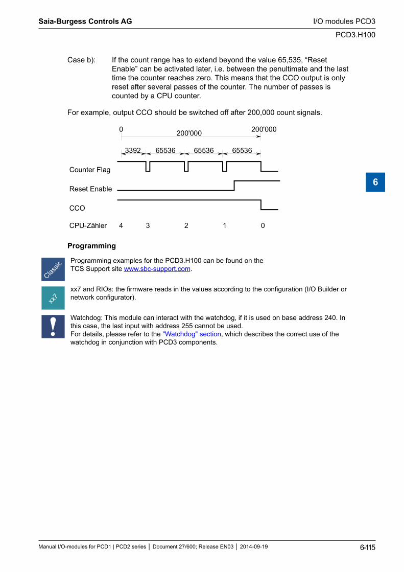
Case b): If the count range has to extend beyond the value 65,535, “Reset Enable” can be activated later, i.e. between the penultimate and the last time the counter reaches zero. This means that the CCO output is only reset after several passes of the counter. The number of passes is counted by a CPU counter.
For example, output CCO should be switched off after 200,000 count signals.
Counter Flag
Reset Enable
CCO
0 200'000
3392 65536 65536 65536
200'000
CPU-Zähler 3 2 1 04
Programming
Programming examples for the PCD3.H100 can be found on the TCS Support site www.sbc-support.com.
xx7 and RIOs: the firmware reads in the values according to the configuration (I/O Builder or network configurator).
Watchdog: This module can interact with the watchdog, if it is used on base address 240. In this case, the last input with address 255 cannot be used. For details, please refer to the "Watchdog" section, which describes the correct use of the watchdog in conjunction with PCD3 components.
Saia-Burgess Controls AG
Manual I/O-modules for PCD1 | PCD2 series Document 27/600; Release EN03 2014-09-19 6-115
I/O modules PCD3
PCD3.H100
6
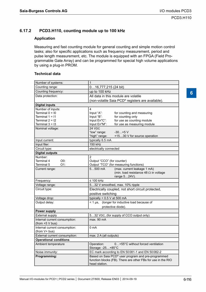
6.17.2 PCD3.H110, counting module up to 100 kHz
Application
Measuring and fast counting module for general counting and simple motion control tasks; also for specific applications such as frequency measurement, period and pulse length measurement, etc. The module is equipped with an FPGA (Field Pro-grammable Gate Array) and can be programmed for special high volume applications by using a plug-in PROM.
Technical data
Number of systems: 1Counting range: 0…16,777,215 (24 bit)Counting frequency: up to 100 kHzData protection: All data in this module are volatile
(non-volatile Saia PCD® registers are available).Digital inputsNumber of inputs: Terminal 0 = I0 Terminal 1 = I1 Terminal 2 = I2 Terminal 3 = I3
4 Input “A”: for counting and measuring Input “B”: for counting only Input En"C”: for use as counting module Input En"M”: for use as measuring module
Nominal voltage: 24 VDC “low” range: -30…+5 V “high” range: +15…30 V for source operation
Input current: typically 6.5 mAInput filer: 150 kHzCircuit type: electrically connectedDigital outputsNumber: Terminal 4 O0: Terminal 5 O1:
2 Output “CCO” (for counter) Output “TCO” (for measuring functions)
Current range: 5…500 mA (max. current leakage 1 mA) (min. load resistance 48 Ω in voltage range 5…24V).
Frequency: ≤ 100 kHzVoltage range: 5…32 V smoothed, max. 10% ripple Circuit type: Electrically coupled, not short circuit protected,
positive switchingVoltage drop: typically < 0.5 V at 500 mAOutput delay: < 1 µs, (longer for inductive load because of
protective diode).Power supplyExternal supply 5…32 VDC, (for supply of CCO output only)Internal current consumption: (from +5 V bus)
max. 90 mA
Internal current consumption: (from V+ bus)
0 mA
External current consumption: max. 2 A (all outputs)Operational conditionsAmbient temperature Operation: 0…+55°C without forced ventilation
Storage: -25…+85°C Noise immunity: EC mark according to EN 50 081-1 and EN 50 082-2Programming: Based on Saia PCD® user program and pre-programmed
function blocks (FB). There are other FBs for use in the RIO head station.
Saia-Burgess Controls AG
Manual I/O-modules for PCD1 | PCD2 series Document 27/600; Release EN03 2014-09-19 6-116
I/O modules PCD3
PCD3.H110
6
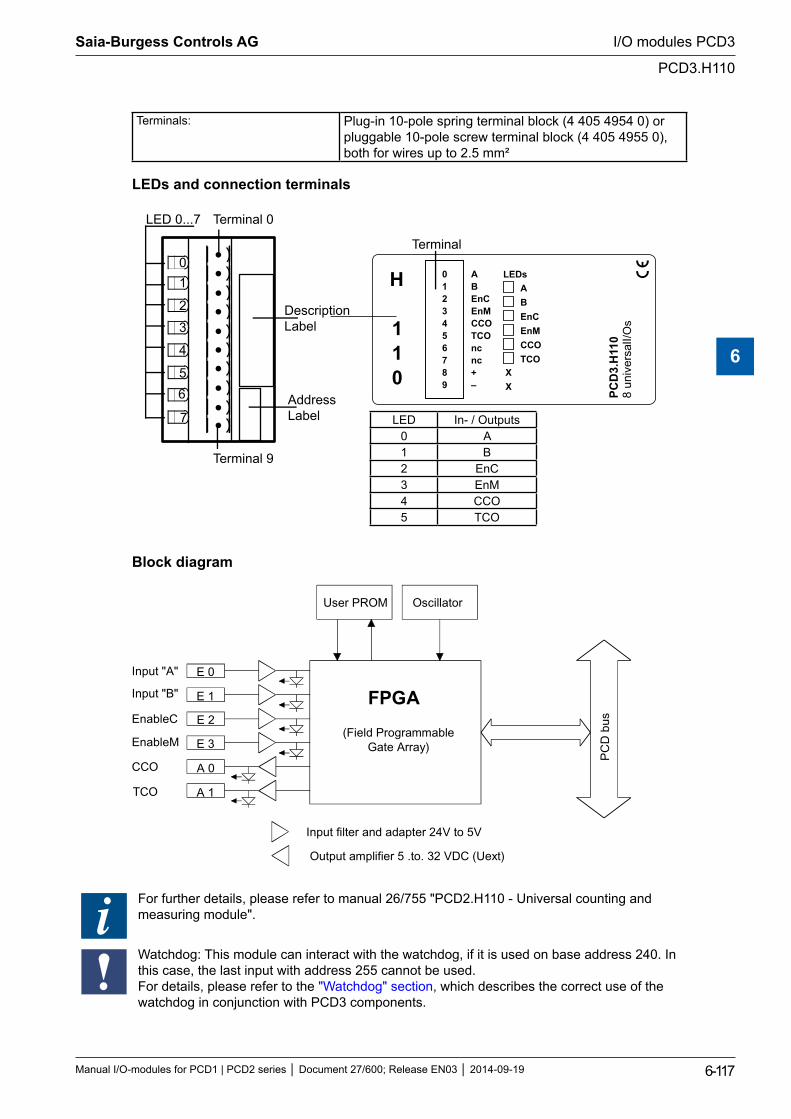
Terminals: Plug-in 10-pole spring terminal block (4 405 4954 0) or pluggable 10-pole screw terminal block (4 405 4955 0), both for wires up to 2.5 mm²
LEDs and connection terminals
01
2
3
4
56
7
LED 0...7 Terminal 0
DescriptionLabel
AddressLabel
ABEnCEnMCCOTCOncnc+–
0123456789
PCD
3.H
110
8 un
iver
salI/
Os
ABEnCEnMCCOTCO
LEDs
Terminal 9
Terminal
H
110
LED In- / Outputs0 A1 B2 EnC3 EnM4 CCO5 TCO
Block diagram
E 0
E 1
E 2
E 3
A 0
A 1
User PROM Oscillator
FPGA
(Field ProgrammableGate Array)
PC
D b
us
Input filter and adapter 24V to 5V
Output amplifier 5 .to. 32 VDC (Uext)
Input "A"
Input "B"
EnableC
EnableM
CCO
TCO
For further details, please refer to manual 26/755 "PCD2.H110 - Universal counting and measuring module".
Watchdog: This module can interact with the watchdog, if it is used on base address 240. In this case, the last input with address 255 cannot be used. For details, please refer to the "Watchdog" section, which describes the correct use of the watchdog in conjunction with PCD3 components.
Saia-Burgess Controls AG
Manual I/O-modules for PCD1 | PCD2 series Document 27/600; Release EN03 2014-09-19 6-117
I/O modules PCD3
PCD3.H110
6
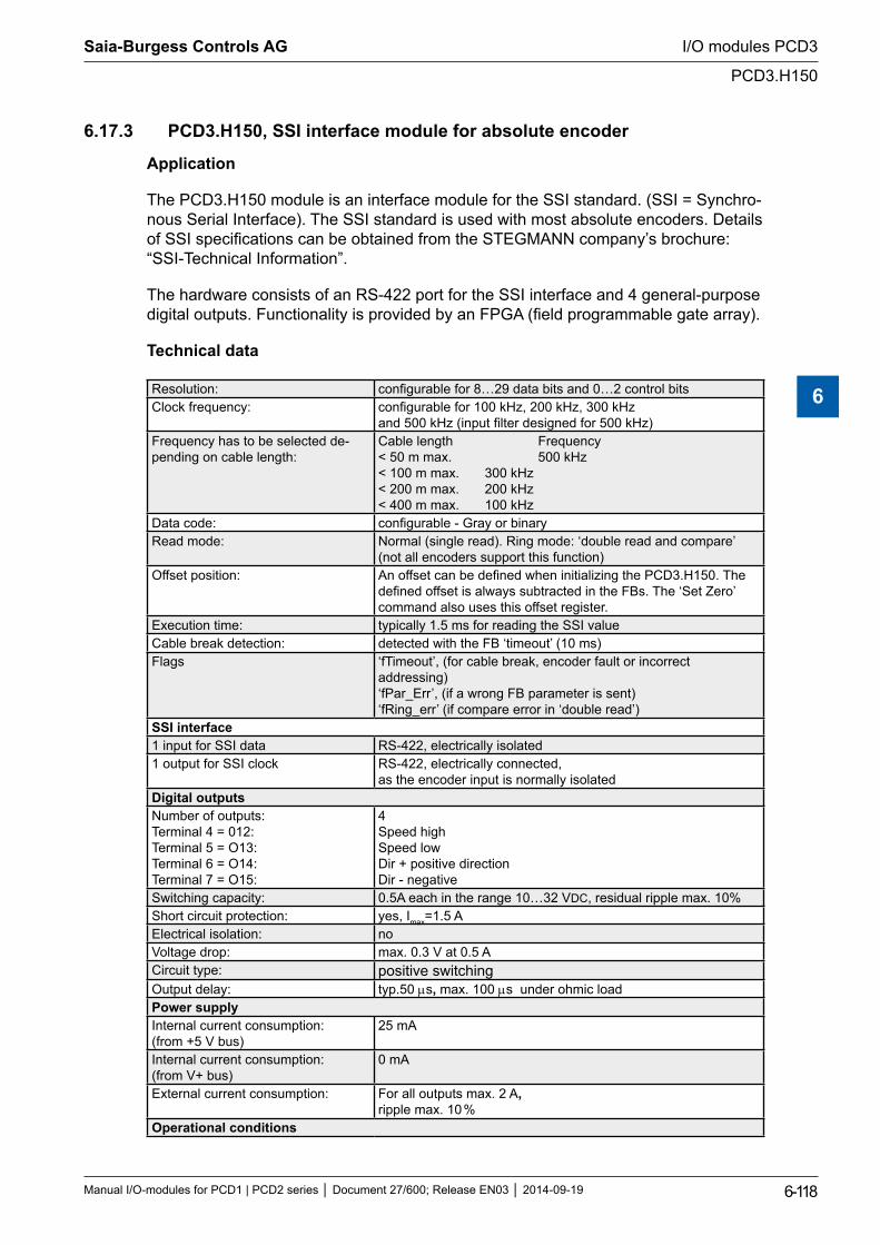
6.17.3 PCD3.H150, SSI interface module for absolute encoder
Application
The PCD3.H150 module is an interface module for the SSI standard. (SSI = Synchro-nous Serial Interface). The SSI standard is used with most absolute encoders. Details of SSI specifications can be obtained from the STEGMANN company’s brochure: “SSI-Technical Information”.
The hardware consists of an RS-422 port for the SSI interface and 4 general-purpose digital outputs. Functionality is provided by an FPGA (field programmable gate array).
Technical data
Resolution: configurable for 8…29 data bits and 0…2 control bitsClock frequency: configurable for 100 kHz, 200 kHz, 300 kHz
and 500 kHz (input filter designed for 500 kHz)Frequency has to be selected de-pending on cable length:
Cable length Frequency < 50 m max. 500 kHz < 100 m max. 300 kHz < 200 m max. 200 kHz < 400 m max. 100 kHz
Data code: configurable - Gray or binaryRead mode: Normal (single read). Ring mode: ‘double read and compare’
(not all encoders support this function) Offset position: An offset can be defined when initializing the PCD3.H150. The
defined offset is always subtracted in the FBs. The ‘Set Zero’ command also uses this offset register.
Execution time: typically 1.5 ms for reading the SSI valueCable break detection: detected with the FB ‘timeout’ (10 ms)Flags ‘fTimeout’, (for cable break, encoder fault or incorrect
addressing) ‘fPar_Err’, (if a wrong FB parameter is sent) ‘fRing_err’ (if compare error in ‘double read’)
SSI interface1 input for SSI data RS-422, electrically isolated1 output for SSI clock RS-422, electrically connected,
as the encoder input is normally isolatedDigital outputsNumber of outputs: Terminal 4 = 012: Terminal 5 = O13: Terminal 6 = O14: Terminal 7 = O15:
4 Speed high Speed low Dir + positive direction Dir - negative
Switching capacity: 0.5A each in the range 10…32 VDC, residual ripple max. 10%Short circuit protection: yes, Imax=1.5 AElectrical isolation: noVoltage drop: max. 0.3 V at 0.5 ACircuit type: positive switchingOutput delay: typ.50 µs, max. 100 µs under ohmic loadPower supplyInternal current consumption: (from +5 V bus)
25 mA
Internal current consumption: (from V+ bus)
0 mA
External current consumption: For all outputs max. 2 A, ripple max. 10 %
Operational conditions
Saia-Burgess Controls AG
Manual I/O-modules for PCD1 | PCD2 series Document 27/600; Release EN03 2014-09-19 6-118
I/O modules PCD3
PCD3.H150
6
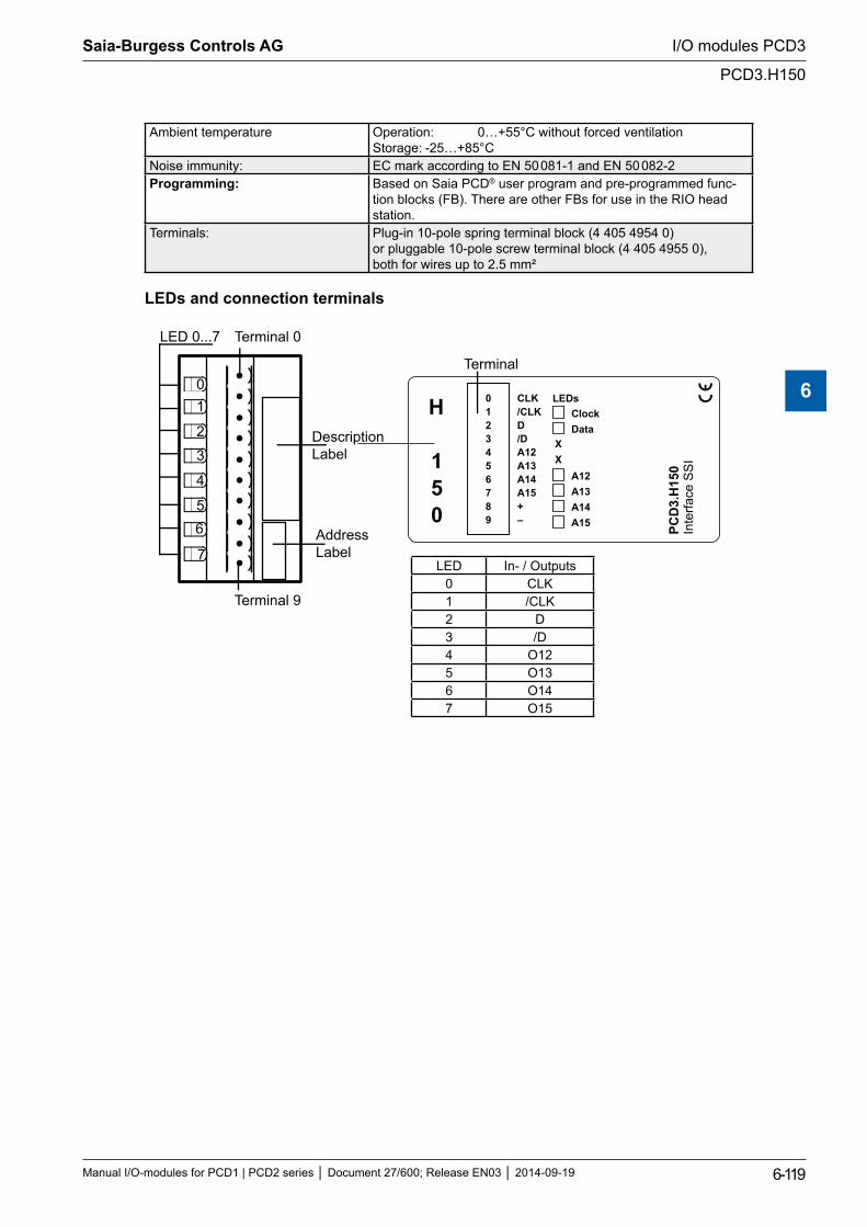
Ambient temperature Operation: 0…+55°C without forced ventilation Storage: -25…+85°C
Noise immunity: EC mark according to EN 50 081-1 and EN 50 082-2Programming: Based on Saia PCD® user program and pre-programmed func-
tion blocks (FB). There are other FBs for use in the RIO head station.
Terminals: Plug-in 10-pole spring terminal block (4 405 4954 0) or pluggable 10-pole screw terminal block (4 405 4955 0), both for wires up to 2.5 mm²
LEDs and connection terminals
01
2
3
4
56
7
LED 0...7 Terminal 0
DescriptionLabel
AddressLabel
PCD
3.H
150
Inte
rface
SS
I
0123456789
CLK
+–
/CLKD/DA12A13A14A15
ClockData
A12A13A14A15
LEDs
Terminal 9
Terminal
H
150
LED In- / Outputs0 CLK1 /CLK2 D3 /D4 O125 O136 O147 O15
Saia-Burgess Controls AG
Manual I/O-modules for PCD1 | PCD2 series Document 27/600; Release EN03 2014-09-19 6-119
I/O modules PCD3
PCD3.H150
6

Block diagram
CLK
/CLK
D
/D
A 12
A 13
User PROM
FPGA
(Field ProgrammableGate Array)
PC
D b
us
Input filter and adaptation 24 V...5 V
Output amplifier 5...32 VDC (Uext)
Clock
/Clock
Data
/Data
Output 12
A 14
A 15
Output 13
Output 14
Output 15
For further details, please refer to manual 26/761 "PCD2.H150 - SSI interface for absolute encoder".
Watchdog: This module can interact with the watchdog, if it is used on base address 240. In this case, the last input with address 255 cannot be used. For details, please refer to the "Watchdog" section, which describes the correct use of the watchdog in conjunction with PCD3 components.
Saia-Burgess Controls AG
Manual I/O-modules for PCD1 | PCD2 series Document 27/600; Release EN03 2014-09-19 6-120
I/O modules PCD3
PCD3.H150
6
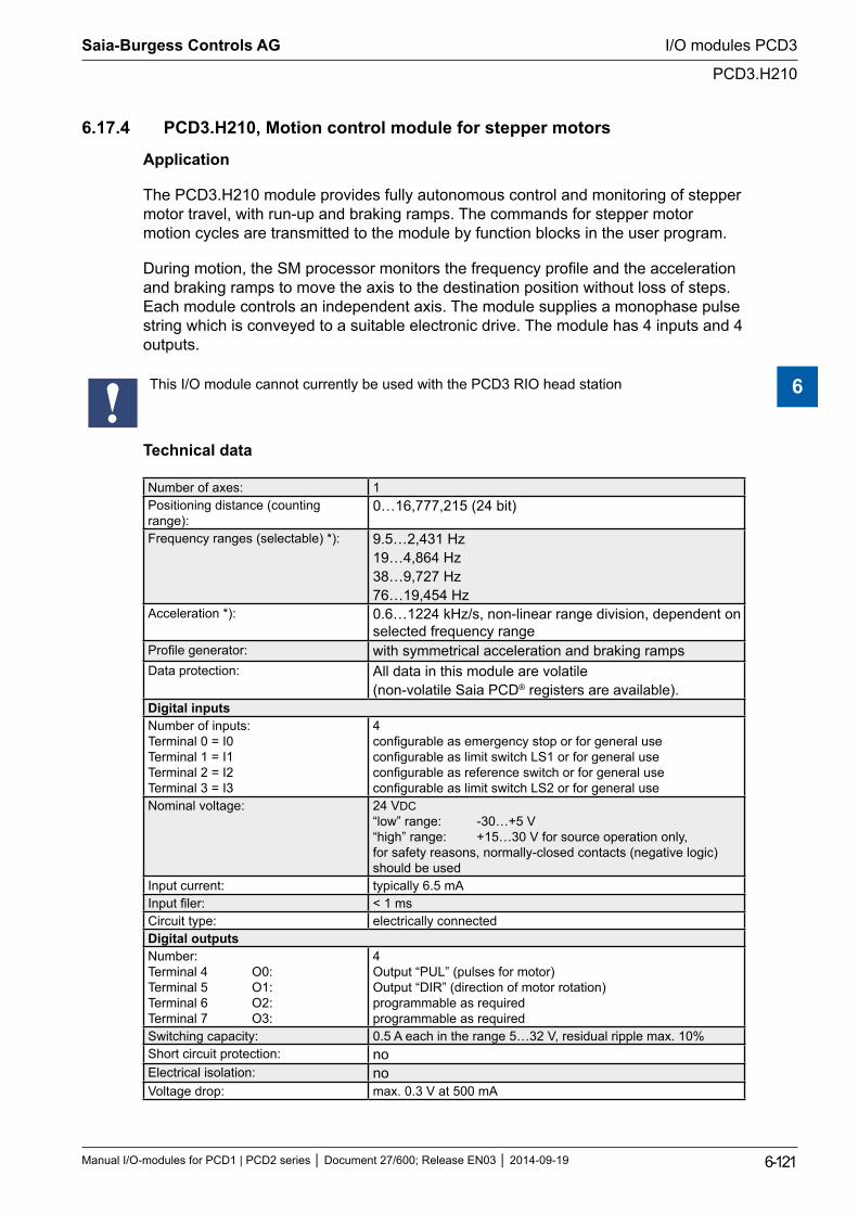
6.17.4 PCD3.H210, Motion control module for stepper motors
Application
The PCD3.H210 module provides fully autonomous control and monitoring of stepper motor travel, with run-up and braking ramps. The commands for stepper motor motion cycles are transmitted to the module by function blocks in the user program.
During motion, the SM processor monitors the frequency profile and the acceleration and braking ramps to move the axis to the destination position without loss of steps. Each module controls an independent axis. The module supplies a monophase pulse string which is conveyed to a suitable electronic drive. The module has 4 inputs and 4 outputs.
This I/O module cannot currently be used with the PCD3 RIO head station
Technical data
Number of axes: 1Positioning distance (counting range):
0…16,777,215 (24 bit)
Frequency ranges (selectable) *): 9.5…2,431 Hz 19…4,864 Hz 38…9,727 Hz 76…19,454 Hz
Acceleration *): 0.6…1224 kHz/s, non-linear range division, dependent on selected frequency range
Profile generator: with symmetrical acceleration and braking rampsData protection: All data in this module are volatile
(non-volatile Saia PCD® registers are available).Digital inputsNumber of inputs: Terminal 0 = I0 Terminal 1 = I1 Terminal 2 = I2 Terminal 3 = I3
4 configurable as emergency stop or for general use configurable as limit switch LS1 or for general use configurable as reference switch or for general use configurable as limit switch LS2 or for general use
Nominal voltage: 24 VDC “low” range: -30…+5 V “high” range: +15…30 V for source operation only, for safety reasons, normally-closed contacts (negative logic) should be used
Input current: typically 6.5 mAInput filer: < 1 msCircuit type: electrically connectedDigital outputsNumber: Terminal 4 O0: Terminal 5 O1: Terminal 6 O2: Terminal 7 O3:
4 Output “PUL” (pulses for motor) Output “DIR” (direction of motor rotation) programmable as required programmable as required
Switching capacity: 0.5 A each in the range 5…32 V, residual ripple max. 10%Short circuit protection: noElectrical isolation: noVoltage drop: max. 0.3 V at 500 mA
Saia-Burgess Controls AG
Manual I/O-modules for PCD1 | PCD2 series Document 27/600; Release EN03 2014-09-19 6-121
I/O modules PCD3
PCD3.H210
6
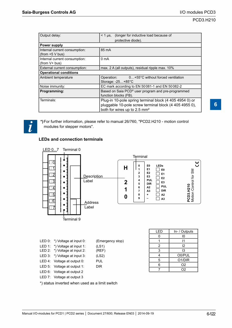
Output delay: < 1 µs, (longer for inductive load because of protective diode).
Power supplyInternal current consumption: (from +5 V bus)
85 mA
Internal current consumption: (from V+ bus)
0 mA
External current consumption: max. 2 A (all outputs), residual ripple max. 10%Operational conditionsAmbient temperature Operation: 0…+55°C without forced ventilation
Storage: -25…+85°CNoise immunity: EC mark according to EN 50 081-1 and EN 50 082-2Programming: Based on Saia PCD® user program and pre-programmed
function blocks (FB).Terminals: Plug-in 10-pole spring terminal block (4 405 4954 0) or
pluggable 10-pole screw terminal block (4 405 4955 0), both for wires up to 2.5 mm²
*) For further information, please refer to manual 26/760, "PCD2.H210 - motion control modules for stepper motors".
LEDs and connection terminals
01
2
3
4
56
7
LED 0...7 Terminal 0
DescriptionLabel
AddressLabel
PCD
3.H
210
Mot
ion
Con
trol f
or S
M
0123456789
E0E1E2E3PULDIRA2A3+–
E0E1E2E3PULDIRA2A3
LEDs
Terminal 9
Terminal
H
210
LED In- / Outputs0 I0
LED 0: *) Voltage at input 0: (Emergency stop)LED 1: *) Voltage at input 1: (LS1) LED 2: *) Voltage at input 2: (REF)LED 3: *) Voltage at input 3: (LS2)LED 4: Voltage at output 0: PULLED 5: Voltage at output 1: DIRLED 6: Voltage at output 2LED 7: Voltage at output 3
*) status inverted when used as a limit switch
1 I12 I23 I34 O0/PUL5 O1/DIR6 O27 O2
Saia-Burgess Controls AG
Manual I/O-modules for PCD1 | PCD2 series Document 27/600; Release EN03 2014-09-19 6-122
I/O modules PCD3
PCD3.H210
6
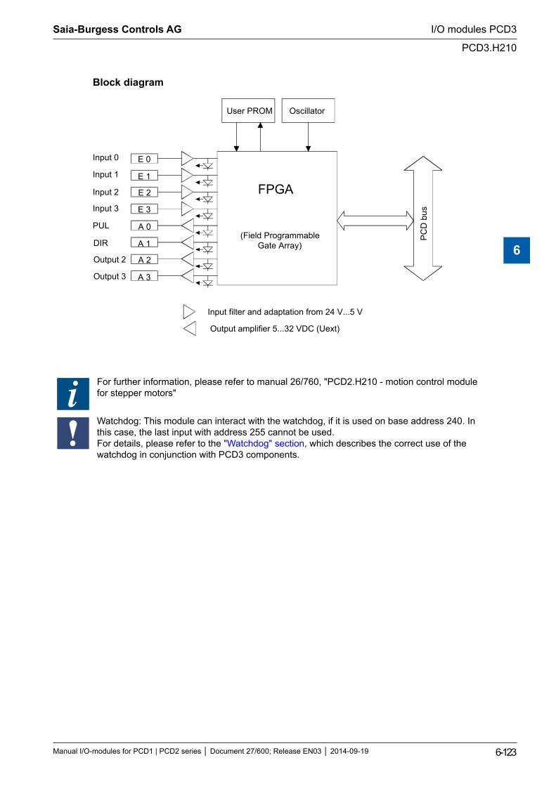
Block diagram
E 0
E 1
E 2
E 3
A 0
A 1
User PROM Oscillator
FPGA
(Field ProgrammableGate Array)
PC
D b
us
Input filter and adaptation from 24 V...5 V
Output amplifier 5...32 VDC (Uext)
Input 1
Input 2
Input 3
PUL
DIR
A 2
A 3
Output 2
Output 3
Input 0
For further information, please refer to manual 26/760, "PCD2.H210 - motion control module for stepper motors"
Watchdog: This module can interact with the watchdog, if it is used on base address 240. In this case, the last input with address 255 cannot be used. For details, please refer to the "Watchdog" section, which describes the correct use of the watchdog in conjunction with PCD3 components.
Saia-Burgess Controls AG
Manual I/O-modules for PCD1 | PCD2 series Document 27/600; Release EN03 2014-09-19 6-123
I/O modules PCD3
PCD3.H210
6
6.17.5 PCD3.H31x, motion control module for servo-motors, 1-axis encoder
Application
The PCD3.H31x motion control module is an intelligent I/O module. The module is used to position a single axis with variable speed control DC or AC servomotors. This requires the drive unit to have a power stage and incremental shaft encoder for capturing position or speed.
Each module contains a single-chip processor that independently controls every movement according to parameters supplied by the user program (velocity, acceleration and destination position). The axes are controlled independently of each other, which means that no interpolation is possible to trace curved paths. On the other hand, linking of multiple axes (point-point) in quasi-synchronous operation cane be programmed.
This I/O module cannot currently be used with the PCD3 RIO head station
Technical data
Number of axes: 1Motion parameters31-bit registers are used for destination position, velocity and acceleration, numerical range ± 230
Position: Resolution selectable (depending on mechanical factor)Velocity: Resolution selectable (depending on mechanical factor)Acceleration: Resolution selectable (depending on mechanical factor)PID controller: Sample time 341 μs, programmable proportional, integral and
differential factors. Sample time for differential part can be pro-grammed separately.
Analogue controller output: Velocity set point ±10 V (resolution 12 bit)Counting frequency: max. 50 kHzDigital inputs to PCD3.H310Number of inputs: 1 encoder A, B, IN, 1 reference inputNominal voltage: 24 V typically
“low” range: 0…+4 V “high” range: +15…30 V for source operation only,
Input current: typically 6 mACircuit type: electrically connectedReaction time: 30 µsEncoder frequency: max. 100 kHzDigital inputs to PCD3.H311Number of inputs: 1 encoder A, /A, B, /B, IN, /IN, (no reference input)Input voltage: 5 V typicallySignal level: antivalent inputs according to RS-422Hysteresis: max. 200 mVLine termination resistance: 150 ΩEncoder frequency: max. 100 kHzAnalogue outputs for PCD3.H310/311Analogue controller output: resolution 12 bit (with sign bit)Short circuit protection: yesElectrical isolation: noOutput voltage *): ±10 V, accuracy of adjustment ±5 mV
Saia-Burgess Controls AG
Manual I/O-modules for PCD1 | PCD2 series Document 27/600; Release EN03 2014-09-19 6-124
I/O modules PCD3
PCD3.H31x
6
Circuit type: positive switchingMinimum load impedance: 3 kΩ*) Balancing output voltage is carried out in the factory. The user is strongly advised not to adjust the tuning potentiometer.5 V supply for 5 V encoder for PCD3.H3115 V output: 5 V supply of encoderShort circuit protection: yesElectrical isolation: noOutput voltage: 5 VMax. load current: Short circuit current:
300 mA 400 mA (this current also loads the +5 V Bus on the module)
Power supplyInternal current consumption: (from +5 V bus)
max. 140 mA typically 125 mA
Internal current consumption: (from V+ bus)
0 mA
External current consumption: max. 15 mA, typically 10 mA, residual ripple max. 10 %Operational conditionsAmbient temperature Operation: 0…+55°C without forced ventilation
Storage: -25…+85°CNoise immunity: EC mark according to EN 50 081-1 and EN 50 082-2Programming: Based on Saia PCD® user program and pre-programmed function
blocks (FB).Terminals: Plug-in 10-pole spring terminal block (4 405 4954 0) or plug-
gable 10-pole screw terminal block (4 405 4955 0), both for wires up to 2.5 mm²
Saia-Burgess Controls AG
Manual I/O-modules for PCD1 | PCD2 series Document 27/600; Release EN03 2014-09-19 6-125
I/O modules PCD3
PCD3.H31x
6
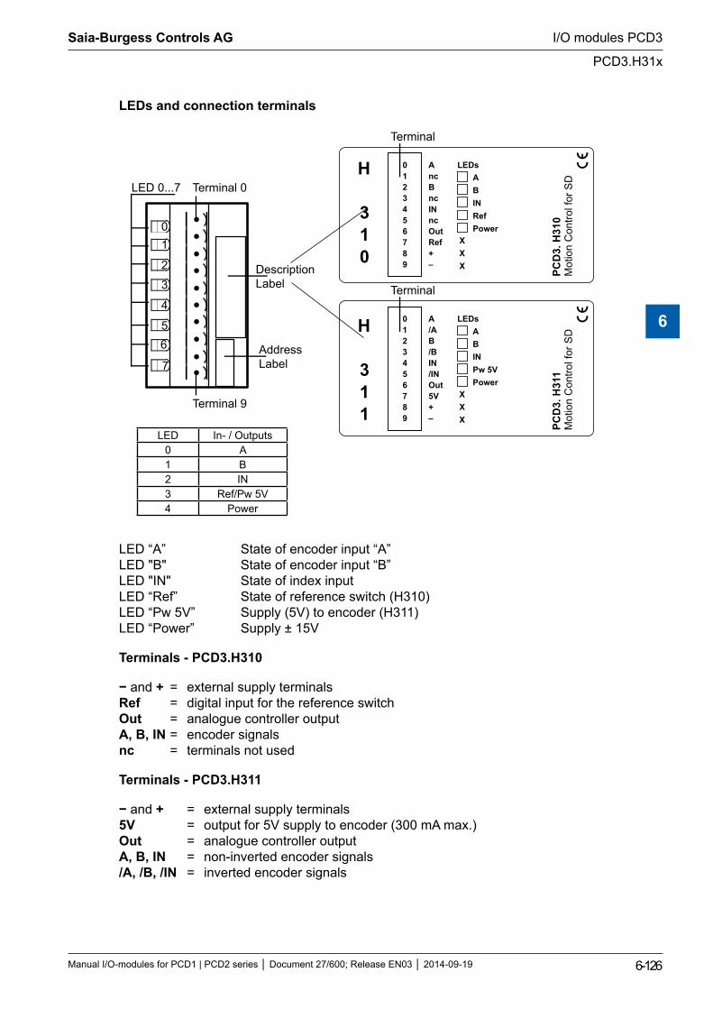
LEDs and connection terminals
01
2
3
4
56
7
LED 0...7 Terminal 0
DescriptionLabel
AddressLabel
PCD
3.0
H31
Mot
ion
Con
trol f
or S
D
0123456789
AncBncINncOutRef+–
ABINRefPower
LEDs
Terminal 9
Terminal
PCD
3.H
311
Mot
ion
Con
trol f
or S
D
0123456789
A/AB/BIN/INOut5V+–
ABINPw 5VPower
LEDs
Terminal
H
310
H
311
LED In- / Outputs0 A1 B2 IN3 Ref/Pw 5V4 Power
LED “A” State of encoder input “A” LED "B" State of encoder input “B” LED "IN" State of index input LED “Ref” State of reference switch (H310) LED “Pw 5V” Supply (5V) to encoder (H311) LED “Power” Supply ± 15V
Terminals - PCD3.H310
− and + = external supply terminals Ref = digital input for the reference switch Out = analogue controller output A, B, IN = encoder signals nc = terminals not used
Terminals - PCD3.H311
− and + = external supply terminals 5V = output for 5V supply to encoder (300 mA max.) Out = analogue controller output A, B, IN = non-inverted encoder signals /A, /B, /IN = inverted encoder signals
Saia-Burgess Controls AG
Manual I/O-modules for PCD1 | PCD2 series Document 27/600; Release EN03 2014-09-19 6-126
I/O modules PCD3
PCD3.H31x
6
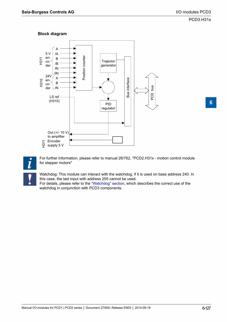
Block diagram
A/AB/B
/ININ
ABIN
5 Ven-co-der
24Ven-co-der
LS ref(H310)
PIDregulator
Trajectorgenerator
Out (+/- 10 V)to amplifier
Bus
inte
rface
PC
D b
us
Pos
ition
cou
nter
H31
0H
311
Encodersupply 5 VH
311
For further information, please refer to manual 26/762, "PCD2.H31x - motion control module for stepper motors"
Watchdog: This module can interact with the watchdog, if it is used on base address 240. In this case, the last input with address 255 cannot be used. For details, please refer to the "Watchdog" section, which describes the correct use of the watchdog in conjunction with PCD3 components.
Saia-Burgess Controls AG
Manual I/O-modules for PCD1 | PCD2 series Document 27/600; Release EN03 2014-09-19 6-127
I/O modules PCD3
PCD3.H31x
6
6.18 Miscellaneous modules
PCD3.S100 Workshop simulator unit
Saia-Burgess Controls AG
Manual I/O-modules for PCD1 | PCD2 series Document 27/600; Release EN03 2014-09-19 6-128
I/O modules PCD3
Miscellaneous modules
6
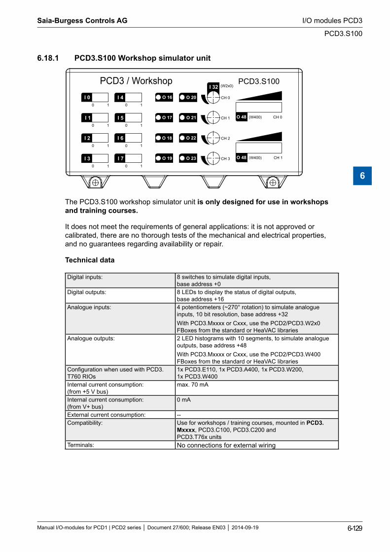
6.18.1 PCD3.S100 Workshop simulator unit
0
0
0
0
0
0
0
0
1
1
1
1
1
1
1
1
(W400)
(W400)
(W2x0)PCD3.S100orkshop
The PCD3.S100 workshop simulator unit is only designed for use in workshops and training courses.
It does not meet the requirements of general applications: it is not approved or calibrated, there are no thorough tests of the mechanical and electrical properties, and no guarantees regarding availability or repair.
Technical data
Digital inputs: 8 switches to simulate digital inputs, base address +0
Digital outputs: 8 LEDs to display the status of digital outputs, base address +16
Analogue inputs: 4 potentiometers (~270° rotation) to simulate analogue inputs, 10 bit resolution, base address +32With PCD3.Mxxxx or Cxxx, use the PCD2/PCD3.W2x0 FBoxes from the standard or HeaVAC libraries
Analogue outputs: 2 LED histograms with 10 segments, to simulate analogue outputs, base address +48With PCD3.Mxxxx or Cxxx, use the PCD2/PCD3.W400 FBoxes from the standard or HeaVAC libraries
Configuration when used with PCD3.T760 RIOs
1x PCD3.E110, 1x PCD3.A400, 1x PCD3.W200, 1x PCD3.W400
Internal current consumption: (from +5 V bus)
max. 70 mA
Internal current consumption: (from V+ bus)
0 mA
External current consumption: --Compatibility: Use for workshops / training courses, mounted in PCD3.
Mxxxx, PCD3.C100, PCD3.C200 and PCD3.T76x units
Terminals: No connections for external wiring
Saia-Burgess Controls AG
Manual I/O-modules for PCD1 | PCD2 series Document 27/600; Release EN03 2014-09-19 6-129
I/O modules PCD3
PCD3.S100
6
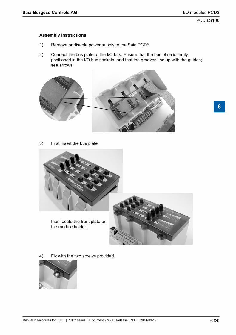
Assembly instructions
1) Remove or disable power supply to the Saia PCD®.
2) Connect the bus plate to the I/O bus. Ensure that the bus plate is firmly positioned in the I/O bus sockets, and that the grooves line up with the guides; see arrows.
3) First insert the bus plate,
then locate the front plate on the module holder.
4) Fix with the two screws provided.
Saia-Burgess Controls AG
Manual I/O-modules for PCD1 | PCD2 series Document 27/600; Release EN03 2014-09-19 6-130
I/O modules PCD3
PCD3.S100
6
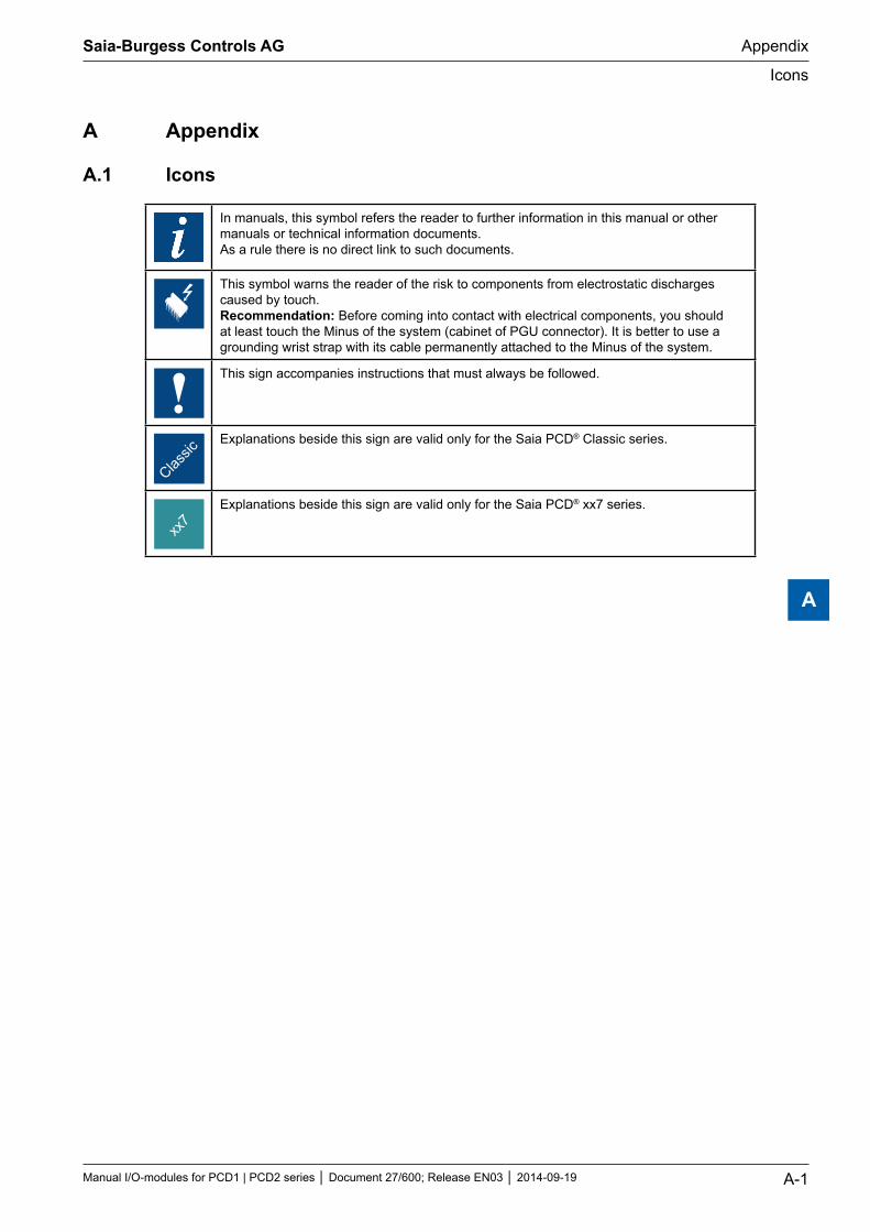
A Appendix
A.1 Icons
In manuals, this symbol refers the reader to further information in this manual or other manuals or technical information documents. As a rule there is no direct link to such documents.
This symbol warns the reader of the risk to components from electrostatic discharges caused by touch. Recommendation: Before coming into contact with electrical components, you should at least touch the Minus of the system (cabinet of PGU connector). It is better to use a grounding wrist strap with its cable permanently attached to the Minus of the system.
This sign accompanies instructions that must always be followed.
Explanations beside this sign are valid only for the Saia PCD® Classic series.
Explanations beside this sign are valid only for the Saia PCD® xx7 series.
Saia-Burgess Controls AG
Manual I/O-modules for PCD1 | PCD2 series Document 27/600; Release EN03 2014-09-19 A-1
Appendix
Icons
A
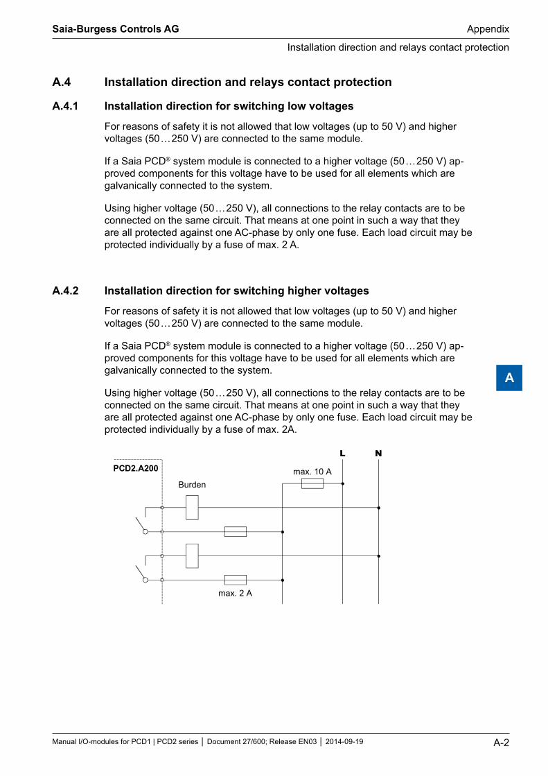
A.4 Installation direction and relays contact protection
A.4.1 Installation direction for switching low voltages
For reasons of safety it is not allowed that low voltages (up to 50 V) and higher voltages (50 … 250 V) are connected to the same module.
If a Saia PCD® system module is connected to a higher voltage (50 … 250 V) ap-proved components for this voltage have to be used for all elements which are galvanically connected to the system.
Using higher voltage (50 … 250 V), all connections to the relay contacts are to be connected on the same circuit. That means at one point in such a way that they are all protected against one AC-phase by only one fuse. Each load circuit may be protected individually by a fuse of max. 2 A.
A.4.2 Installation direction for switching higher voltages
For reasons of safety it is not allowed that low voltages (up to 50 V) and higher voltages (50 … 250 V) are connected to the same module.
If a Saia PCD® system module is connected to a higher voltage (50 … 250 V) ap-proved components for this voltage have to be used for all elements which are galvanically connected to the system.
Using higher voltage (50 … 250 V), all connections to the relay contacts are to be connected on the same circuit. That means at one point in such a way that they are all protected against one AC-phase by only one fuse. Each load circuit may be protected individually by a fuse of max. 2A.
PCD2.A200
L N
Burdenmax. 10 A
max. 2 A
Saia-Burgess Controls AG
Manual I/O-modules for PCD1 | PCD2 series Document 27/600; Release EN03 2014-09-19 A-2
Appendix
Installation direction and relays contact protection
A
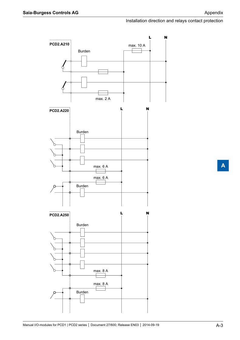
PCD2.A210
L N
Burdenmax. 10 A
max. 2 A
PCD2.A220 L N
Burden
max. 6 A
max. 6 A
Burden
PCD2.A250 L N
Burden
max. 8 A
max. 8 A
Burden
Saia-Burgess Controls AG
Manual I/O-modules for PCD1 | PCD2 series Document 27/600; Release EN03 2014-09-19 A-3
Appendix
Installation direction and relays contact protection
A
A.4.3 Switching inductive loads
Because of the physical properties of inductive loads, it is not possible to discon-nect inductance without interference. This interference must be minimized as far as possible. Although the Saia PCD® is immune to this interference, there are other devices which may be susceptible.
It should be noted here that, as part of the harmonization of standards throughout the EU, EMC standards have applied since 1996 (EMC Directive 89 / 336 / EG). Two firm principles can therefore be stated:
PROTECTION AGAINST INTERFERENCE FROM INDUCTIVE LOADS IS MANDATORY
INTERFERENCE SHOULD BE ELIMINATED AS CLOSE AS POSSIBLE TO ITS SOURCE
Relay contacts on the present module have been wired. However, it is still recom-mended that a protection circuit should be fitted at the load.
(Often available as normal components on standardized contactors and valves).
When switching direct voltage it is urgently recommended that a recovery diode is fitted above the load. This should even take place when, theoretically, an Ohmic load is switched. In practice, there will always be a proportion which is inductive (connection cable, resistance coil, etc.). In this case it should be noted that the switch-off time will be longer.
(Approximate Ta . L / RL * √ (RL * IL / 0,7).
For direct voltage, transistor output modules are recommended.
A.4.4 Relay manufacturer’s information on RC unit dimensioning
Wiring contact protection:The purpose of contact protection wiring is to suppress switch arcing (“sparks”) and thereby prolong the lifetime of the contacts. All protection wiring has disad-vantages as well as advantages. For the cancellation of arcing by means of an RC unit, see adjacent diagram.
When switching off load circuits with inductive components (e.g. relay coils and magnet coils) the interruption of current results in overvoltage (standard induc-tance) at the switching contacts. This may amount to many times the operating voltage and so threaten the insulation of the load circuit. The resultant breaking spark leads to rapid wear of the relay contacts. For this reason contact protection wiring is particularly important with inductive load circuits. Values for the RC com-bination can also be determined from the adjacent diagram. However, for voltage U it is necessary to use the overvoltage arising from the interruption of current (e.g. measurable with an oscillograph). Current must be calculated from this volt-age and the known resistance, against which the voltage was measured.
Screening units should only use anti-interference capacitors that comply with VDE 0565 T1 class X2. These capacitors are switchproof and designed for particularly high switching surges. They can also run directly on mains voltage.
Saia-Burgess Controls AG
Manual I/O-modules for PCD1 | PCD2 series Document 27/600; Release EN03 2014-09-19 A-4
Appendix
Installation direction and relays contact protection
A
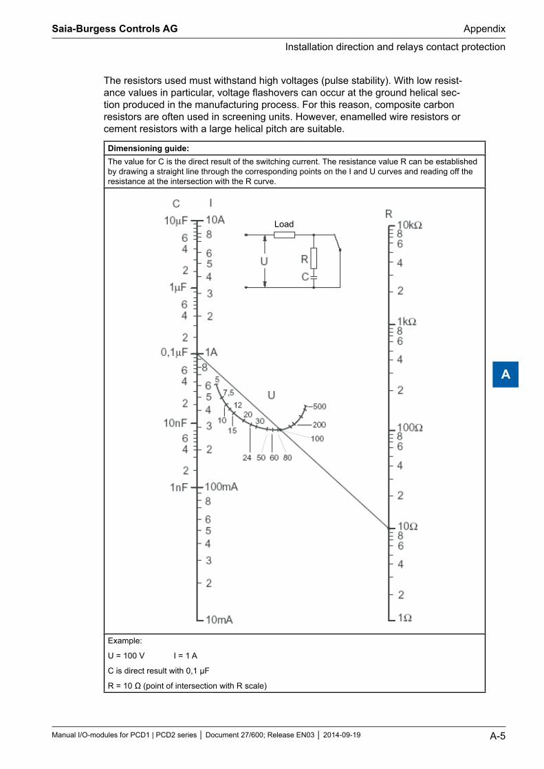
The resistors used must withstand high voltages (pulse stability). With low resist-ance values in particular, voltage flashovers can occur at the ground helical sec-tion produced in the manufacturing process. For this reason, composite carbon resistors are often used in screening units. However, enamelled wire resistors or cement resistors with a large helical pitch are suitable.
Dimensioning guide:The value for C is the direct result of the switching current. The resistance value R can be established by drawing a straight line through the corresponding points on the I and U curves and reading off the resistance at the intersection with the R curve.
Load
Example:
U = 100 V I = 1 A
C is direct result with 0,1 μF
R = 10 Ω (point of intersection with R scale)
Saia-Burgess Controls AG
Manual I/O-modules for PCD1 | PCD2 series Document 27/600; Release EN03 2014-09-19 A-5
Appendix
Installation direction and relays contact protection
A
A.6 Contact
Saia-Burgess Controls AG Bahnhofstrasse 18 3280 Murten Switzerland
Phone .......................................... +41 26 672 72 72 Fax ............................................... +41 26 672 74 99
Email support: ............................. [email protected] Supportsite: ................................ www.sbc-support.com SBC site: ..................................... www.saia-pcd.com International Represetatives & SBC Sales Companies: .............. www.saia-pcd.com/contact
Postal address for returns from customers of the Swiss Sales office
Saia-Burgess Controls AG Service Après-Vente Bahnhofstrasse 18 3280 Murten Switzerland
Saia-Burgess Controls AG
Manual I/O-modules for PCD1 | PCD2 series Document 27/600; Release EN03 2014-09-19 A-6
Appendix
Adress of Saia Burgess Controls
A


![Product Modules - Algorithm › Downloads › Product_Modules... · 2005-12-21 · 1 Product Modules * Product Modules [Pvt.] Limited Sub Modules Brief Description Of The Features](https://img.pdfslide.us/doc/110x75/5f142811614b4b7bf5198598/product-modules-a-downloads-a-productmodules-2005-12-21-1-product.jpg)


![[Photovoltaic modules (PV modules) – Universal Waste ... · 24/12/2019 · [Photovoltaic modules (PV modules) – Universal Waste Management ] Proposed Regulation Text R-2017-04](https://img.pdfslide.us/doc/110x75/5f4ce350b9360a33274df70d/photovoltaic-modules-pv-modules-a-universal-waste-24122019-photovoltaic.jpg)