Embed Size (px)
Citation preview
Manual
MiniContac-RS
V 5.0, English
Ite
mnum
be
r:1
20
40
5

Manual 5.0 Rev.: 27.08.2008 1
Manual MiniContac RS
English, Version 5.0
LPKF Laser & Electronics AG
Osteriede 7
D-30827 Garbsen
Phone: ++ 49 - 51 31 - 70 95 - 0
Fax: ++ 49 - 51 31 - 70 95 - 90
E-mail: [email protected]
Website: http://www.lpkf.com
2 MiniContac RS
Copyright (c) 2008 LPKF AGAny distribution or copying of this manual or parts of this manual in any form as well as processing of its contents require written permission of LPKF AG. Subject to modifications. Trademarks: HP-GL is a Trademark of Hewlett-Packard Comp. All other trademarks belong to the respective companies.
Overview
Manual 5.0 Rev.: 27.08.2008 3
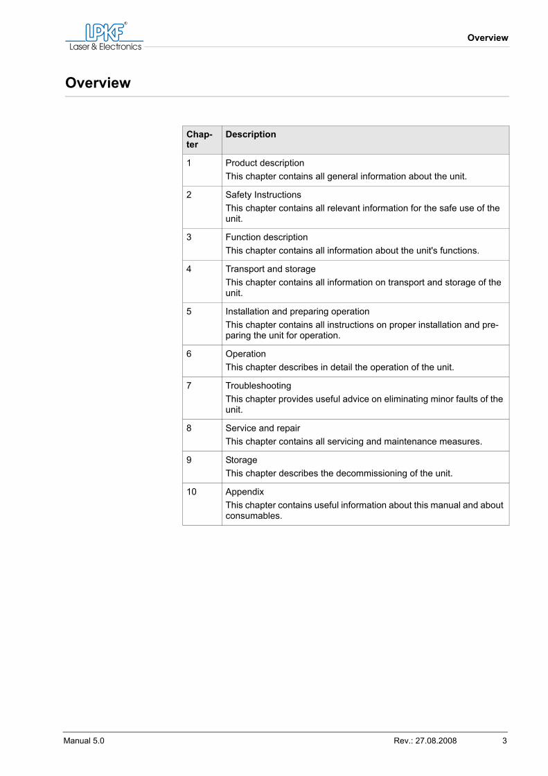
Overview
Chap-ter
Description
1 Product descriptionThis chapter contains all general information about the unit.
2 Safety InstructionsThis chapter contains all relevant information for the safe use of the unit.
3 Function descriptionThis chapter contains all information about the unit's functions.
4 Transport and storageThis chapter contains all information on transport and storage of the unit.
5 Installation and preparing operationThis chapter contains all instructions on proper installation and pre-paring the unit for operation.
6 OperationThis chapter describes in detail the operation of the unit.
7 TroubleshootingThis chapter provides useful advice on eliminating minor faults of the unit.
8 Service and repairThis chapter contains all servicing and maintenance measures.
9 StorageThis chapter describes the decommissioning of the unit.
10 AppendixThis chapter contains useful information about this manual and about consumables.
Symbols used
4 MiniContac RS
Symbols used
Formatting conventions
Bold text is used to emphasise important information.Menu items are printed in BOLD CAPITALS.ITALIC CAPITALS identify the names of the chemicals used.
WARNING
› This symbol warns of hazards to life or health.
CAUTION
› This symbol warns of hazards of material damage.
Tip: This symbol is used for advice on how to prevent malfunctions or how to improve process flow.
Contents
Manual 5.0 Rev.: 27.08.2008 5
Contents
1 Product description 9
1.1 Brand and type identification . . . . . . . . . . . . . . . . . . . . . . . . . . . . . . . . . . . . . . 91.2 Scope of delivery . . . . . . . . . . . . . . . . . . . . . . . . . . . . . . . . . . . . . . . . . . . . . . . . 91.3 Manufacturer/Distributors/Customer Service . . . . . . . . . . . . . . . . . . . . . . . . 101.4 Certification . . . . . . . . . . . . . . . . . . . . . . . . . . . . . . . . . . . . . . . . . . . . . . . . . . . 10
1.4.1 Declaration of Conformity (German) . . . . . . . . . . . . . . . . . . . . . . . . . . . . . . . 101.4.2 Declaration of conformity . . . . . . . . . . . . . . . . . . . . . . . . . . . . . . . . . . . . . . . 12
1.5 Accessories and consumables . . . . . . . . . . . . . . . . . . . . . . . . . . . . . . . . . . . 13
2 Safety Instructions 15
3 Function description 17
3.1 Function and scope of application . . . . . . . . . . . . . . . . . . . . . . . . . . . . . . . . . 173.1.1 Unit description . . . . . . . . . . . . . . . . . . . . . . . . . . . . . . . . . . . . . . . . . . . . . . . 173.1.2 Description of the individual tanks . . . . . . . . . . . . . . . . . . . . . . . . . . . . . . . . 203.1.3 Fill level sensor . . . . . . . . . . . . . . . . . . . . . . . . . . . . . . . . . . . . . . . . . . . . . . . 213.1.4 Control panel . . . . . . . . . . . . . . . . . . . . . . . . . . . . . . . . . . . . . . . . . . . . . . . . 213.1.5 Menus . . . . . . . . . . . . . . . . . . . . . . . . . . . . . . . . . . . . . . . . . . . . . . . . . . . . . . 223.1.6 Reverse Pulse Plating. . . . . . . . . . . . . . . . . . . . . . . . . . . . . . . . . . . . . . . . . . 25
3.2 Safe and correct use . . . . . . . . . . . . . . . . . . . . . . . . . . . . . . . . . . . . . . . . . . . . 263.3 Specifications . . . . . . . . . . . . . . . . . . . . . . . . . . . . . . . . . . . . . . . . . . . . . . . . . . 263.4 Power supply . . . . . . . . . . . . . . . . . . . . . . . . . . . . . . . . . . . . . . . . . . . . . . . . . . 273.5 Energy consumption . . . . . . . . . . . . . . . . . . . . . . . . . . . . . . . . . . . . . . . . . . . . 273.6 Emission . . . . . . . . . . . . . . . . . . . . . . . . . . . . . . . . . . . . . . . . . . . . . . . . . . . . . . 27
4 Transport and storage 29
4.1 Transport . . . . . . . . . . . . . . . . . . . . . . . . . . . . . . . . . . . . . . . . . . . . . . . . . . . . . . 294.2 Storage . . . . . . . . . . . . . . . . . . . . . . . . . . . . . . . . . . . . . . . . . . . . . . . . . . . . . . . 29
5 Installation and preparing operation 31
5.1 Safety measures before installing . . . . . . . . . . . . . . . . . . . . . . . . . . . . . . . . . 31
Contents
6 MiniContac RS
5.2 Unpacking, disposal of packing materials . . . . . . . . . . . . . . . . . . . . . . . . . . . 31Unpacking the unit . . . . . . . . . . . . . . . . . . . . . . . . . . . . . . . . . . . . . . . . . . . . 31
5.3 Setting up and putting into service . . . . . . . . . . . . . . . . . . . . . . . . . . . . . . . . . 315.3.1 Assembling. . . . . . . . . . . . . . . . . . . . . . . . . . . . . . . . . . . . . . . . . . . . . . . . . . 32
Installing the unit . . . . . . . . . . . . . . . . . . . . . . . . . . . . . . . . . . . . . . . . . . . . . 32Mounting the copper anodes . . . . . . . . . . . . . . . . . . . . . . . . . . . . . . . . . . . . 33Inserting the thermometer . . . . . . . . . . . . . . . . . . . . . . . . . . . . . . . . . . . . . . 34Checking/Setting the mains voltage setting . . . . . . . . . . . . . . . . . . . . . . . . . 34Connecting the mains cable. . . . . . . . . . . . . . . . . . . . . . . . . . . . . . . . . . . . . 35
5.3.2 Filling the tanks . . . . . . . . . . . . . . . . . . . . . . . . . . . . . . . . . . . . . . . . . . . . . . 35Filling in chemicals . . . . . . . . . . . . . . . . . . . . . . . . . . . . . . . . . . . . . . . . . . . . 35
5.3.3 Initialisation . . . . . . . . . . . . . . . . . . . . . . . . . . . . . . . . . . . . . . . . . . . . . . . . . 36Initialising the unit. . . . . . . . . . . . . . . . . . . . . . . . . . . . . . . . . . . . . . . . . . . . . 36
5.4 Storage and conservation in the intervals of normal usage . . . . . . . . . . . . . 375.5 Intended operators . . . . . . . . . . . . . . . . . . . . . . . . . . . . . . . . . . . . . . . . . . . . . . 375.6 Storage of the documentation . . . . . . . . . . . . . . . . . . . . . . . . . . . . . . . . . . . . . 37
6 Operation 39
6.1 Changing settings . . . . . . . . . . . . . . . . . . . . . . . . . . . . . . . . . . . . . . . . . . . . . . . 39Changing profile . . . . . . . . . . . . . . . . . . . . . . . . . . . . . . . . . . . . . . . . . . . . . . 39Calculating the current . . . . . . . . . . . . . . . . . . . . . . . . . . . . . . . . . . . . . . . . . 40
6.2 Latching the circuit board holder. . . . . . . . . . . . . . . . . . . . . . . . . . . . . . . . . . . 41Latching the circuit board holder . . . . . . . . . . . . . . . . . . . . . . . . . . . . . . . . . 41
6.3 The through-plating process . . . . . . . . . . . . . . . . . . . . . . . . . . . . . . . . . . . . . . 436.3.1 Work prerequisites . . . . . . . . . . . . . . . . . . . . . . . . . . . . . . . . . . . . . . . . . . . . 436.3.2 Work process . . . . . . . . . . . . . . . . . . . . . . . . . . . . . . . . . . . . . . . . . . . . . . . . 44
Fastening the circuit board. . . . . . . . . . . . . . . . . . . . . . . . . . . . . . . . . . . . . . 44Phase 1: Degreasing the circuit board . . . . . . . . . . . . . . . . . . . . . . . . . . . . . 44Phase 2: Cleaning the circuit board . . . . . . . . . . . . . . . . . . . . . . . . . . . . . . . 44Phase 3: Activating the circuit board . . . . . . . . . . . . . . . . . . . . . . . . . . . . . . 45Phase 4: Preparing the copper plating. . . . . . . . . . . . . . . . . . . . . . . . . . . . . 46Phase 4: Starting copper plating . . . . . . . . . . . . . . . . . . . . . . . . . . . . . . . . . 46Phase 4: Checking the circuit board . . . . . . . . . . . . . . . . . . . . . . . . . . . . . . 46Phase 4: Resuming the copper plating . . . . . . . . . . . . . . . . . . . . . . . . . . . . 46Phase 4: Finishing the copper-plating . . . . . . . . . . . . . . . . . . . . . . . . . . . . . 47Rinsing and drying the circuit board. . . . . . . . . . . . . . . . . . . . . . . . . . . . . . . 47
6.4 Process sequence . . . . . . . . . . . . . . . . . . . . . . . . . . . . . . . . . . . . . . . . . . . . . . . 496.4.1 Standard circuit board . . . . . . . . . . . . . . . . . . . . . . . . . . . . . . . . . . . . . . . . . 496.4.2 Multi-layer circuit board . . . . . . . . . . . . . . . . . . . . . . . . . . . . . . . . . . . . . . . . 50
Contents
Manual 5.0 Rev.: 27.08.2008 7
6.4.3 Flexible circuit board. . . . . . . . . . . . . . . . . . . . . . . . . . . . . . . . . . . . . . . . . . . 516.5 Waste Disposal . . . . . . . . . . . . . . . . . . . . . . . . . . . . . . . . . . . . . . . . . . . . . . . . . 52
7 Troubleshooting 53
7.1 Safety advice . . . . . . . . . . . . . . . . . . . . . . . . . . . . . . . . . . . . . . . . . . . . . . . . . . 537.2 Error codes . . . . . . . . . . . . . . . . . . . . . . . . . . . . . . . . . . . . . . . . . . . . . . . . . . . . 537.3 Other fault indicators . . . . . . . . . . . . . . . . . . . . . . . . . . . . . . . . . . . . . . . . . . . . 547.4 Simple troubleshooting . . . . . . . . . . . . . . . . . . . . . . . . . . . . . . . . . . . . . . . . . . 54
7.4.1 Cleaning the anode rails . . . . . . . . . . . . . . . . . . . . . . . . . . . . . . . . . . . . . . . . 54Removing deposits on the anode rails . . . . . . . . . . . . . . . . . . . . . . . . . . . . . 54
7.4.2 Easing frame movement . . . . . . . . . . . . . . . . . . . . . . . . . . . . . . . . . . . . . . . . 55Easing frame movement . . . . . . . . . . . . . . . . . . . . . . . . . . . . . . . . . . . . . . . . 55
7.4.3 Replacing the fuse . . . . . . . . . . . . . . . . . . . . . . . . . . . . . . . . . . . . . . . . . . . . 55Replacing the fuse . . . . . . . . . . . . . . . . . . . . . . . . . . . . . . . . . . . . . . . . . . . . 55
7.5 Customer service . . . . . . . . . . . . . . . . . . . . . . . . . . . . . . . . . . . . . . . . . . . . . . . 56
8 Service and repair 57
8.1 Routine inspection . . . . . . . . . . . . . . . . . . . . . . . . . . . . . . . . . . . . . . . . . . . . . . 578.2 Service and repair by user. . . . . . . . . . . . . . . . . . . . . . . . . . . . . . . . . . . . . . . . 57
8.2.1 Unit . . . . . . . . . . . . . . . . . . . . . . . . . . . . . . . . . . . . . . . . . . . . . . . . . . . . . . . . 578.2.2 Chemical Baths. . . . . . . . . . . . . . . . . . . . . . . . . . . . . . . . . . . . . . . . . . . . . . . 57
Filtering bath 4 . . . . . . . . . . . . . . . . . . . . . . . . . . . . . . . . . . . . . . . . . . . . . . . 59Adding SHINE 400 . . . . . . . . . . . . . . . . . . . . . . . . . . . . . . . . . . . . . . . . . . . . 59Draining the tanks. . . . . . . . . . . . . . . . . . . . . . . . . . . . . . . . . . . . . . . . . . . . . 60
9 Storage 63
9.1 Decommissioning . . . . . . . . . . . . . . . . . . . . . . . . . . . . . . . . . . . . . . . . . . . . . . 63Decommissioning the unit. . . . . . . . . . . . . . . . . . . . . . . . . . . . . . . . . . . . . . . 63Packing the unit . . . . . . . . . . . . . . . . . . . . . . . . . . . . . . . . . . . . . . . . . . . . . . 63
9.2 Storage . . . . . . . . . . . . . . . . . . . . . . . . . . . . . . . . . . . . . . . . . . . . . . . . . . . . . . . 649.3 Disposal . . . . . . . . . . . . . . . . . . . . . . . . . . . . . . . . . . . . . . . . . . . . . . . . . . . . . . 64
Disposing of the unit . . . . . . . . . . . . . . . . . . . . . . . . . . . . . . . . . . . . . . . . . . . 64
10 Appendix 65
10.1 List of figures. . . . . . . . . . . . . . . . . . . . . . . . . . . . . . . . . . . . . . . . . . . . . . . . . . 65
Contents
8 MiniContac RS
10.2 List of tables . . . . . . . . . . . . . . . . . . . . . . . . . . . . . . . . . . . . . . . . . . . . . . . . . . . 6510.3 Through-plating log . . . . . . . . . . . . . . . . . . . . . . . . . . . . . . . . . . . . . . . . . . . . . 6610.4 Analysis results (German) . . . . . . . . . . . . . . . . . . . . . . . . . . . . . . . . . . . . . . . . 67
10.4.1 Analysis result 1 . . . . . . . . . . . . . . . . . . . . . . . . . . . . . . . . . . . . . . . . . . . . . 6710.4.2 Analysis result 1 (cont.) . . . . . . . . . . . . . . . . . . . . . . . . . . . . . . . . . . . . . . . 6810.4.3 Analysis result 2 . . . . . . . . . . . . . . . . . . . . . . . . . . . . . . . . . . . . . . . . . . . . . 6910.4.4 Analysis result 3 . . . . . . . . . . . . . . . . . . . . . . . . . . . . . . . . . . . . . . . . . . . . . 7010.4.5 Analysis result 3 (cont.) . . . . . . . . . . . . . . . . . . . . . . . . . . . . . . . . . . . . . . . 7110.4.6 Analysis result 3 (cont.) . . . . . . . . . . . . . . . . . . . . . . . . . . . . . . . . . . . . . . . 7210.4.7 Analysis result 4 . . . . . . . . . . . . . . . . . . . . . . . . . . . . . . . . . . . . . . . . . . . . . 7310.4.8 Analysis result 4 (cont.) . . . . . . . . . . . . . . . . . . . . . . . . . . . . . . . . . . . . . . . 7410.4.9 Analysis result 4 (cont.) . . . . . . . . . . . . . . . . . . . . . . . . . . . . . . . . . . . . . . . 7510.4.10 Analysis report . . . . . . . . . . . . . . . . . . . . . . . . . . . . . . . . . . . . . . . . . . . . . 76
10.5 Analysis results . . . . . . . . . . . . . . . . . . . . . . . . . . . . . . . . . . . . . . . . . . . . . . . . 7710.5.1 Analysis result 1 . . . . . . . . . . . . . . . . . . . . . . . . . . . . . . . . . . . . . . . . . . . . . 7710.5.2 Analysis result 1 (cont.) . . . . . . . . . . . . . . . . . . . . . . . . . . . . . . . . . . . . . . . 7810.5.3 Analysis result 2 . . . . . . . . . . . . . . . . . . . . . . . . . . . . . . . . . . . . . . . . . . . . . 7910.5.4 Analysis result 3 . . . . . . . . . . . . . . . . . . . . . . . . . . . . . . . . . . . . . . . . . . . . . 8010.5.5 Analysis result 3 (cont.) . . . . . . . . . . . . . . . . . . . . . . . . . . . . . . . . . . . . . . . 8110.5.6 Analysis result 3 (cont.) . . . . . . . . . . . . . . . . . . . . . . . . . . . . . . . . . . . . . . . 8210.5.7 Analysis result 4 . . . . . . . . . . . . . . . . . . . . . . . . . . . . . . . . . . . . . . . . . . . . . 8310.5.8 Analysis result 4 (cont.) . . . . . . . . . . . . . . . . . . . . . . . . . . . . . . . . . . . . . . . 8410.5.9 Analysis result 4 (cont.) . . . . . . . . . . . . . . . . . . . . . . . . . . . . . . . . . . . . . . . 8510.5.10 Analysis report . . . . . . . . . . . . . . . . . . . . . . . . . . . . . . . . . . . . . . . . . . . . . 86
10.6 Glossary . . . . . . . . . . . . . . . . . . . . . . . . . . . . . . . . . . . . . . . . . . . . . . . . . . . . . . 87
Product description
Manual 5.0 Rev.: 27.08.2008 9
1. Product description
1.1 Brand and type identification
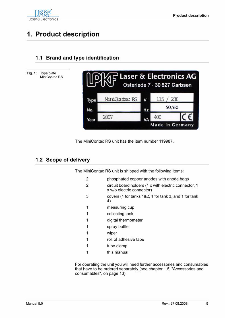
The MiniContac RS unit has the item number 119987.
1.2 Scope of delivery
The MiniContac RS unit is shipped with the following items:
For operating the unit you will need further accessories and consumables that have to be ordered separately (see chapter 1.5‚ "Accessories and consumables", on page 13).
Fig. 1: Type plate MiniContac RS
2 phosphated copper anodes with anode bags2 circuit board holders (1 x with electric connector, 1
x w/o electric connector)3 covers (1 for tanks 1&2, 1 for tank 3, and 1 for tank
4)1 measuring cup1 collecting tank1 digital thermometer1 spray bottle1 wiper1 roll of adhesive tape1 tube clamp1 this manual
Manufacturer/Distributors/Customer Service
10 MiniContac RS
1.3 Manufacturer/Distributors/Customer Service
1.4 Certification
1.4.1 Declaration of conformity (German)
EG-Konformitätserklärung nach Maschinenrichtlinie 98/37/EG, Anhang II ADer Hersteller / Inverkehrbringer
erklärt hiermit, dass folgendes Produkt
den Bestimmungen der (den) oben gekennzeichneten Richtlinie(n) - ein-schließlich deren zum Zeitpunkt der Erklärung geltenden Änderungen - entspricht.Wir unterhalten ein von der BVQI zertifiziertes Qualitätssicherungs-system nach ISO 9001 und haben daher bei der Entwicklung und Her-stellung nachstehende EG Richtlinien und EN Normen beachtet.
LPKF Laser & Electronics AGOsteriede 7D-30827 GarbsenGermany
Phone + 49 - 51 31 - 70 95 - 0 Fax + 49 - 51 31 - 70 95 - 90E-mail [email protected] http://www.lpkf.com
LPKF Laser & Electronics AGOsteriede 730827 GarbsenGermany
Produktbezeichnung: Anlage zur Durchkontaktie-rung von Leiterplatten
Serien-/Typenbezeichnung: MiniContac RS
Product description
Manual 5.0 Rev.: 27.08.2008 11
Folgende harmonisierte Normen wurden angewandt: • EN 349:1993 Sicherheit von Maschinen - Mindestabstände zur Ver-
meidung des Quetschens von Körperteilen• EN 292-1:1991Sicherheit von Maschinen - Grundbegriffe, allge-
meine Gestaltungsleitsätze - Teil 1: Grundsätzliche Terminologie, Methodik
• EN 292-2:1991+A1:1995Sicherheit von Maschinen - Grundbegriffe, allgemeine Gestaltungsleitsätze - Teil 2: Technische Leitsätze und Spezifikationen
• EN 1050:1996 Sicherheit von Maschinen - Leitsätze zur Risikobeur-teilung
• EN 626-1:1994Sicherheit von Maschinen - Reduzierung des Gesundheitsrisikos durch Gefahrstoffe, die von Maschinen ausgehen - Teil 1: Grundsätze und Festlegungen für Maschinenhersteller
• EN 60204-1:1997Sicherheit von Maschinen - Elektrische Ausrüstung von Maschinen - Teil 1: Allgemeine Anforderungen
• EN 61000-3-2:2000Elektromagnetische Verträglichkeit (EMV) - Teil 3-2: Grenzwerte - Grenzwerte für Oberschwingungsströme (Geräte-Eingangsstrom bis einschließlich 16 A je Leiter)
• EN 61000-6-2:2001Elektromagnetische Verträglichkeit (EMV) - Teil 6-2 - Fachgrundnormen - Störfestigkeit - Industriebereich
• EN 61000-6-3:2001Elektromagnetische Verträglichkeit (EMV - Teil 6-3: Fachgrundnormen - Fachgrundnorm Störaussendung - Wohnbe-reich, Geschäfts-und Gewerbebereiche sowie Kleinbetriebe
Folgende nationale oder internationale Normen (oder Teile/Klauseln dar-aus) und Spezifikationen wurden angewandt:
• EN55022 Klasse BFunkstörspannung, Funkstörstrahlung• EN61000-4-3 Störfestigkeit• EN61000-4-2 Störfestigkeit• EN61000-4-6 Wechselstrom Netzein- und ausgänge• EN61000-4-4 Wechselstrom Netzein- und ausgänge• EN61000-4-5 Wechselstrom Netzein- und ausgänge• EN61000-4-11Wechselstrom Netzein- und ausgänge
Folgende weitere EU-Richtlinien wurden angewandt:• EMV-Richtlinie 89/336/EWG• Niederspannungsrichtlinie 73/23/EWG
Ort: GarbsenDatum: 25.08.2006
______________________________________Herr Bernd Hackmann (Vorstandsvorsitzender)
Certification
12 MiniContac RS
1.4.2 Declaration of conformity
EC declaration of conformity according to Machine Directive 98/37/EC, Annex II AThe manufacturer / seller
hereby declares that the following product
conforms to provisions of the directive(s) identified above - including the modifications effective at the time of this declaration.We maintain a quality assurance system compliant with ISO 9001 that has been certified by BVQI, which ensures that development and manu-facturing are compliant with the following EC directives and EN stand-ards.The following harmonised standards were applied:
• EN 349:1993 Safety of machinery - Minimum gaps to avoid crushing of parts of the human body
• EN 292-1:1991Safety of machinery - Basic concepts, general princi-ples for design - Part 1: Basic terminology, methodology
• EN 292-2:1991+A1:1995Safety of machinery - Basic concepts, gen-eral principles for design - Part 2: Technical principles and specifica-tions
• EN 1050:1996Safety of machinery - Principles for risk assessment• EN 626-1:1994Safety of machinery - Reduction of risks to health
from hazardous substances emitted from machinery - Part 1: Princi-ples and specifications for machinery manufacturers
• EN 60204-1:1997Safety of machinery - Electrical equipment of machines - Part 1: General Requirements
• EN 61000-3-2:2000Electromagnetic compatibility (EMC) - Part 3-2: Limits - Limits for harmonic current emissions (equipment input cur-rents up to and including 16 A per phase)
• EN 61000-6-2:2001Electromagnetic compatibility (EMC) - Part 6-2 - Generic standards - Immunity for industrial environments
• EN 61000-6-3:2001Electromagnetic compatibility (EMC) - Part 6-3 - Generic standards - Emission standard for residential, commercial and light-industrial environments
The following national and international standards (or parts/clauses thereof) and specifications were observed:
LPKF Laser & Electronics AGOsteriede 7D-30827 GarbsenGermany
Product designation: System for through-plating of circuit boards
Series/type designation: MiniContac RS
Product description
Manual 5.0 Rev.: 27.08.2008 13
• EN55022 Class BRadio interference voltage, radio interference emission
• EN61000-4-3Interference immunity• EN61000-4-2Interference immunity• EN61000-4-6AC mains voltage inputs and outputs• EN61000-4-4AC mains voltage inputs and outputs• EN61000-4-5AC mains voltage inputs and outputs• EN61000-4-11AC mains voltage inputs and outputs
The following additional EC directives were applied:• EMC directive 89/336/EEC• Low-voltage directive 73/23/EEC
Location: Garbsen (Germany)Date: 2006-08-25
______________________________________Mr. Bernd Hackmann (Chairman of the Board)
1.5 Accessories and consumables
The following chemicals that are not included but can be ordered from LPKF are required for through-plating using the MiniContac RS unit:
WARNING
Danger of poisoning! Danger of chemical burns!The chemicals used are poisonous and corrosive.› Always wear protective gloves and goggles when handling the
chemicals.› Do not remove warning labels from the canisters of the chemi-
cals or apply warning labels if not present and store the empty canisters for uncontaminated disposal of used chemicals.
6.00 l CLEANER 110
5.00 l CLEANER 210
4.00 l AKTIVATOR 310
16.00 l COPPER PLATER 400
0.25 l SHINE 400
Accessories and consumables
14 MiniContac RS
You also need:
distilled/de-ionised water
4 Containers/canisters for disposal of spent chemicals
1 Basin/sink for rinsing the circuit boards
1 window wiper with soft blade
Safety Instructions
Manual 5.0 Rev.: 27.08.2008 15
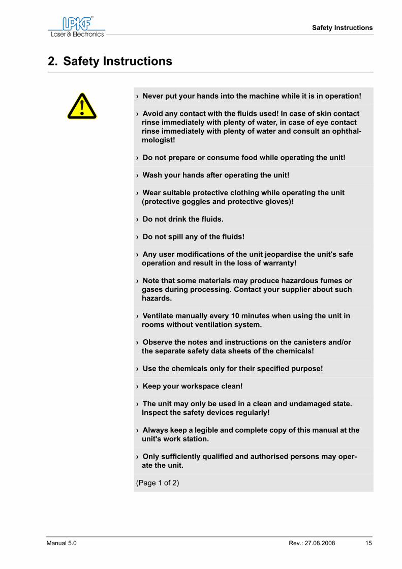
2. Safety Instructions
› Never put your hands into the machine while it is in operation!
› Avoid any contact with the fluids used! In case of skin contact rinse immediately with plenty of water, in case of eye contact rinse immediately with plenty of water and consult an ophthal-mologist!
› Do not prepare or consume food while operating the unit!
› Wash your hands after operating the unit!
› Wear suitable protective clothing while operating the unit (protective goggles and protective gloves)!
› Do not drink the fluids.
› Do not spill any of the fluids!
› Any user modifications of the unit jeopardise the unit's safe operation and result in the loss of warranty!
› Note that some materials may produce hazardous fumes or gases during processing. Contact your supplier about such hazards.
› Ventilate manually every 10 minutes when using the unit in rooms without ventilation system.
› Observe the notes and instructions on the canisters and/or the separate safety data sheets of the chemicals!
› Use the chemicals only for their specified purpose!
› Keep your workspace clean!
› The unit may only be used in a clean and undamaged state. Inspect the safety devices regularly!
› Always keep a legible and complete copy of this manual at the unit's work station.
› Only sufficiently qualified and authorised persons may oper-ate the unit.
(Page 1 of 2)
Safety Instructions
16 MiniContac RS
› Operators must have read this manual and know the safety instructions.
› Take special care to rinse the circuit boards thoroughly. No chemicals of one tank may reach the next tank. The circuit board holders also have to be rinsed thoroughly after use.
› Do not clean the circuit boards with steel wool or similar materials. Even the smallest metal particles can utterly spoil the chemicals.
› Always keep the tanks covered and as clean as possible. This will ensure a long service life of the chemicals.
› Ensure that the holes are flawless. Use the proper drilling parameters.
(Page 2 of 2)
Function description
Manual 5.0 Rev.: 27.08.2008 17
3. Function description
3.1 Function and scope of application
The MiniContac RS unit is made for galvanic through-plating of circuit boards using the black hole process and for galvanic reinforcement of copper surfaces. Via holes of a minimum diameter of 0.2 mm can be plated. The unit can be used for double-sided and multi-layer circuit boards.
3.1.1 Unit description
The unit consists of a durable plastic and metal case containing the tanks for the chemical baths, the motion mechanism, the circuit board holders, and the control panel with status display.The control panel is located on the right of the unit top and the main switch is located on the right side panel of the unit.Note: The MiniContac RS unit does not provide tanks for rinsing or drying. The processed circuit boards have to be rinsed in an external basin or sink.
Tip: The surfaces of the copper deposited in the through-plating proc-ess are smoother and more homogenic when using circuit boards with a protective copper film compared to using circuit boards without such protective film. Thus, always use circuit boards with protective copper film if possible.
Function and scope of application
18 MiniContac RS
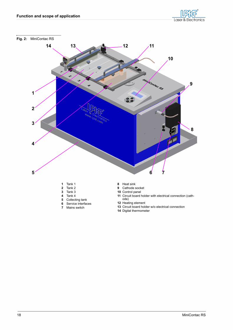
Fig. 2: MiniContac RS
1 Tank 12 Tank 23 Tank 34 Tank 45 Collecting tank6 Service interfaces7 Mains switch
8 Heat sink9 Cathode socket10 Control panel11 Circuit board holder with electrical connection (cath-
ode)12 Heating element13 Circuit board holder w/o electrical connection14 Digital thermometer
1
2
3
4
5 6 7
8
9
10
11121314
Function description
Manual 5.0 Rev.: 27.08.2008 19
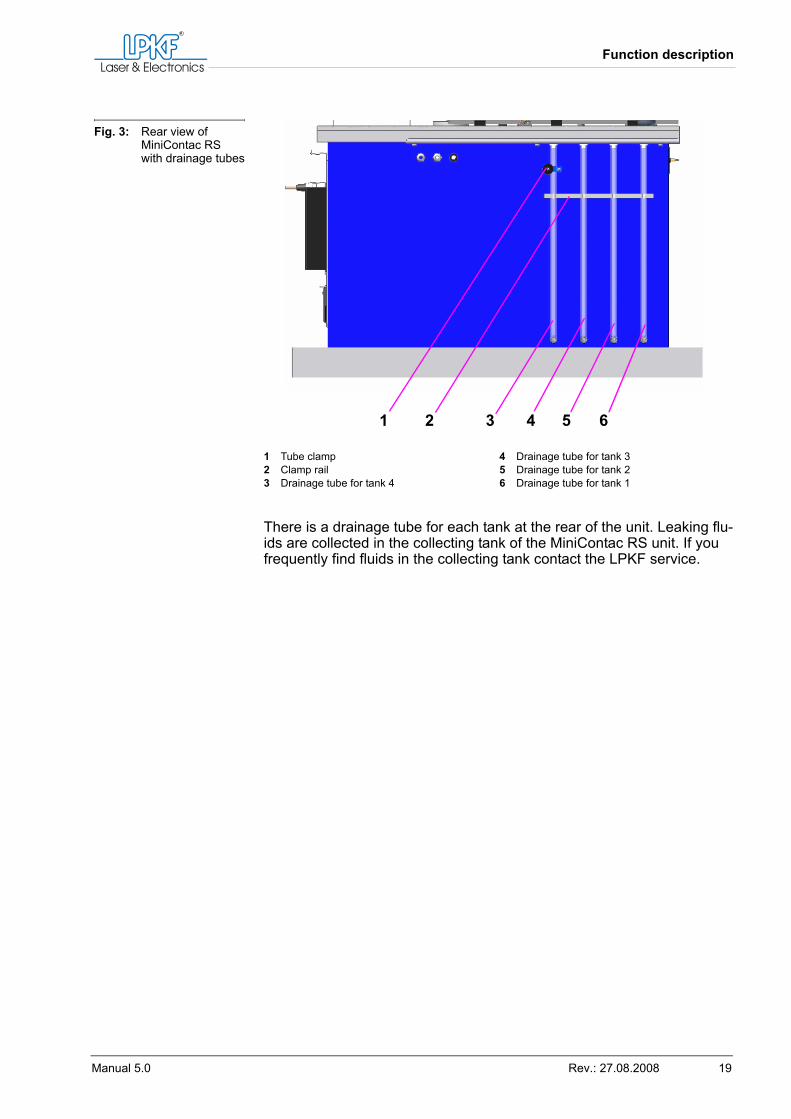
There is a drainage tube for each tank at the rear of the unit. Leaking flu-ids are collected in the collecting tank of the MiniContac RS unit. If you frequently find fluids in the collecting tank contact the LPKF service.
Fig. 3: Rear view of MiniContac RS with drainage tubes
1 Tube clamp2 Clamp rail3 Drainage tube for tank 4
4 Drainage tube for tank 35 Drainage tube for tank 26 Drainage tube for tank 1
1 2 3 4 5 6
Function and scope of application
20 MiniContac RS
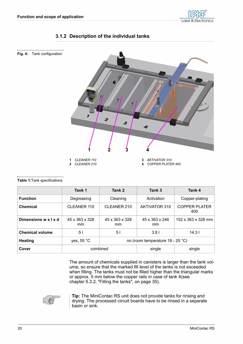
3.1.2 Description of the individual tanks
Table 1:Tank specifications
The amount of chemicals supplied in canisters is larger than the tank vol-ume, so ensure that the marked fill level of the tanks is not exceeded when filling. The tanks must not be filled higher than the triangular marks or approx. 5 mm below the copper rails in case of tank 4(see chapter 5.3.2‚ "Filling the tanks", on page 35).
Fig. 4: Tank configuration
1 CLEANER 1102 CLEANER 210
3 AKTIVATOR 3104 COPPER PLATER 400
1 2 3 4
Tank 1 Tank 2 Tank 3 Tank 4
Function Degreasing Cleaning Activation Copper-plating
Chemical CLEANER 110 CLEANER 210 AKTIVATOR 310 COPPER PLATER 400
Dimensions w x l x d 45 x 363 x 328 mm
45 x 363 x 328 mm
45 x 363 x 246 mm
152 x 363 x 328 mm
Chemical volume 5 l 5 l 3.8 l 14.3 l
Heating yes, 55 °C no (room temperature 18 - 25 °C)
Cover combined single single
Tip: The MiniContac RS unit does not provide tanks for rinsing and drying. The processed circuit boards have to be rinsed in a separate basin or sink.
Function description
Manual 5.0 Rev.: 27.08.2008 21
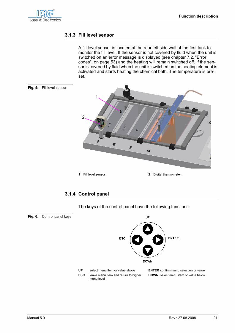
3.1.3 Fill level sensor
A fill level sensor is located at the rear left side wall of the first tank to monitor the fill level. If the sensor is not covered by fluid when the unit is switched on an error message is displayed (see chapter 7.2‚ "Error codes", on page 53) and the heating will remain switched off. If the sen-sor is covered by fluid when the unit is switched on the heating element is activated and starts heating the chemical bath. The temperature is pre-set.
3.1.4 Control panel
The keys of the control panel have the following functions:
Fig. 5: Fill level sensor
1 Fill level sensor 2 Digital thermometer
1
2
Fig. 6: Control panel keys
UP select menu item or value aboveESC leave menu item and return to higher
menu level
ENTER confirm menu selection or valueDOWN select menu item or value below
Function and scope of application
22 MiniContac RS
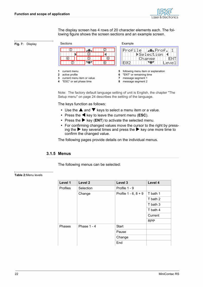
The display screen has 4 rows of 20 character elements each. The fol-lowing figure shows the screen sections and an example screen.
Note: The factory default language setting of unit is English, the chapter "The Setup menu" on page 24 describes the setting of the language.
The keys function as follows:• Use the and keys to select a menu item or a value.• Press the key to leave the current menu (ESC).• Press the key (ENT) to activate the selected menu.• For confirming changed values move the cursor to the right by press-
ing the key several times and press the key one more time to confirm the changed value.
The following pages provide details on the individual menus.
3.1.5 Menus
The following menus can be selected:
Table 2:Menu levels
Fig. 7: Display
1 current menu2 active profile3 current menu item or value4 "ESC“ or set phase time
5 following menu item or explanation6 "ENT“ or remaining time7 message segment 18 message segment 2
1 23
47
586
Sections Example
Level 1 Level 2 Level 3 Level 4Profiles Selection Profile 1 - 9
Change Profile 1 - 6, 8 + 9 T bath 1T bath 2T bath 3T bath 4CurrentRPP
Phases Phase 1 - 4 StartPauseChangeEnd
Function description
Manual 5.0 Rev.: 27.08.2008 23
Profiles menu
Profiles 1 to 7 have been pre-edited by LPKF for use with 9 x 12 “ circuit boards. Profiles 8 and 9 can be defined by the user.
Table 3:Profile data
The data in above table can be changed individually via menu item CHANGE (see chapter 6.1‚ "Changing settings", on page 39).
Setup SaveSignal Yes
NoFact. setMessage Yes
NoLanguage German
EnglishInterface RS 232
EthernetVersionChemie Max. Ah
Cur. AhErgänzt Yes
NoService For LPKF service personnel only! Password required!
Level 1 Level 2 Level 3 Level 4
Pro-file
Application
(values for 9 x 12“ cir-cuit boards)
Via hole diameter
BathTime in minutes
Cur-rentin A
RPP
1 2 3 4
1 standard > 0.4 mm 15 5 15 90 12 off
2 standard with RPP ≤ 0.4 mm 15 5 15 90 12 on
3 multi-layer > 0.4 mm 30 10 25 120 12 off
4 multi-layer with RPP ≤ 0.4 mm 30 10 25 120 12 on
5 flexible circuit board > 0.4 mm 30 5 15 60 10 off
6 flex. circuit board with RPP
≤ 0.4 mm 30 10 25 60 10 on
7 Initialisation see "Initialisation" on page 36
8 User-defined
9 User-defined
Function and scope of application
24 MiniContac RS
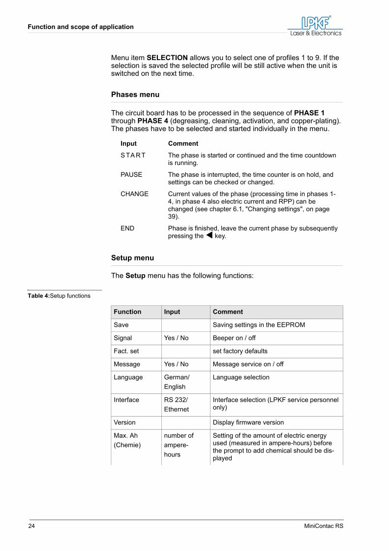
Menu item SELECTION allows you to select one of profiles 1 to 9. If the selection is saved the selected profile will be still active when the unit is switched on the next time.
Phases menu
The circuit board has to be processed in the sequence of PHASE 1 through PHASE 4 (degreasing, cleaning, activation, and copper-plating). The phases have to be selected and started individually in the menu.
Setup menu
The Setup menu has the following functions:
Table 4:Setup functions
Input Comment
S TA RT The phase is started or continued and the time countdown is running.
PAUSE The phase is interrupted, the time counter is on hold, and settings can be checked or changed.
CHANGE Current values of the phase (processing time in phases 1-4, in phase 4 also electric current and RPP) can be changed (see chapter 6.1‚ "Changing settings", on page 39).
END Phase is finished, leave the current phase by subsequently pressing the key.
Function Input Comment
Save Saving settings in the EEPROM
Signal Yes / No Beeper on / off
Fact. set set factory defaults
Message Yes / No Message service on / off
Language German/English
Language selection
Interface RS 232/Ethernet
Interface selection (LPKF service personnel only)
Version Display firmware version
Max. Ah(Chemie)
number ofampere-hours
Setting of the amount of electric energy used (measured in ampere-hours) before the prompt to add chemical should be dis-played
Function description
Manual 5.0 Rev.: 27.08.2008 25
Changing the settings is described in chapter 6.1‚ "Changing settings", on page 39.
The Service menu
The SERVICE menu is used exclusively by LPKF service personnel.
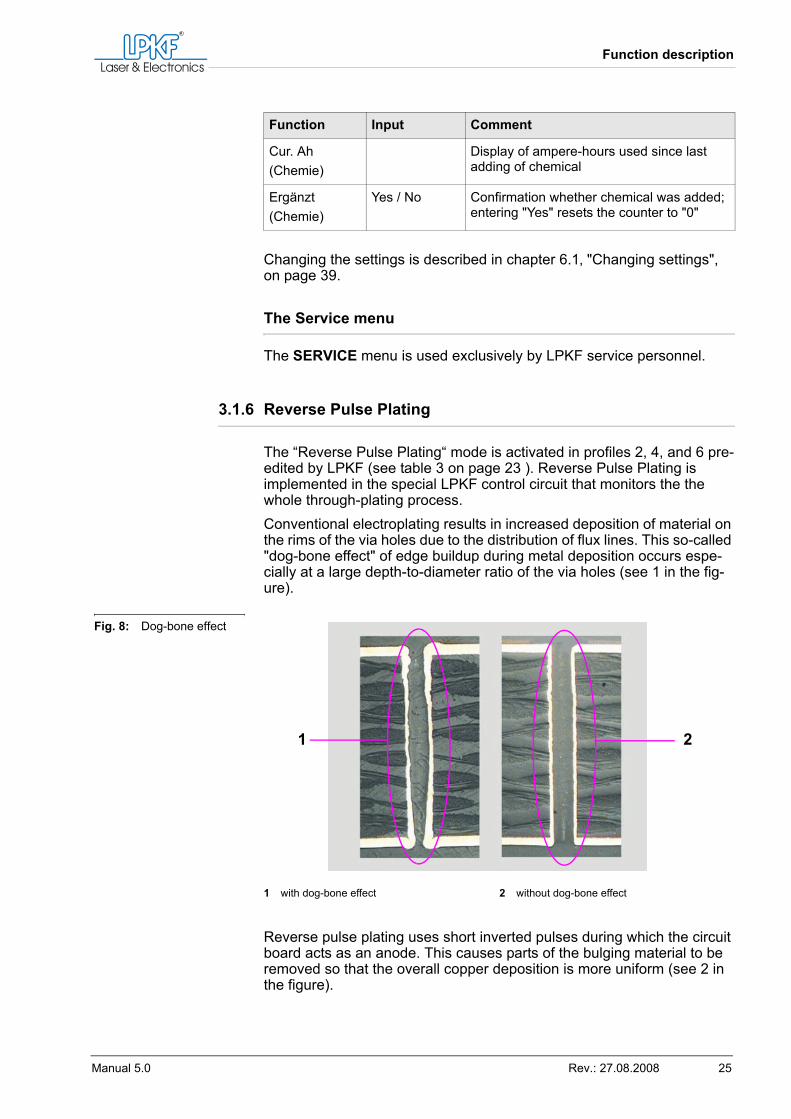
3.1.6 Reverse Pulse Plating
The “Reverse Pulse Plating“ mode is activated in profiles 2, 4, and 6 pre-edited by LPKF (see table 3 on page 23 ). Reverse Pulse Plating is implemented in the special LPKF control circuit that monitors the the whole through-plating process.Conventional electroplating results in increased deposition of material on the rims of the via holes due to the distribution of flux lines. This so-called "dog-bone effect" of edge buildup during metal deposition occurs espe-cially at a large depth-to-diameter ratio of the via holes (see 1 in the fig-ure).
Reverse pulse plating uses short inverted pulses during which the circuit board acts as an anode. This causes parts of the bulging material to be removed so that the overall copper deposition is more uniform (see 2 in the figure).
Cur. Ah(Chemie)
Display of ampere-hours used since last adding of chemical
Ergänzt(Chemie)
Yes / No Confirmation whether chemical was added; entering "Yes" resets the counter to "0"
Function Input Comment
Fig. 8: Dog-bone effect
1 with dog-bone effect 2 without dog-bone effect
1 2
Safe and correct use
26 MiniContac RS
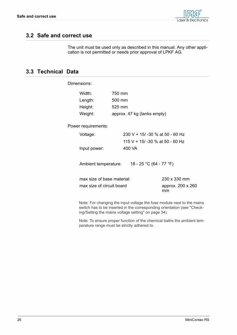
3.2 Safe and correct use
The unit must be used only as described in this manual. Any other appli-cation is not permitted or needs prior approval of LPKF AG.
3.3 Technical Data
Dimensions:
Power requirements:
Note: For changing the input voltage the fuse module next to the mains switch has to be inserted in the corresponding orientation (see "Check-ing/Setting the mains voltage setting" on page 34).
Note: To ensure proper function of the chemical baths the ambient tem-perature range must be strictly adhered to.
Width: 750 mmLength: 500 mmHeight: 525 mmWeight: approx. 47 kg (tanks empty)
Voltage: 230 V + 15/ -30 % at 50 - 60 Hz115 V + 15/ -30 % at 50 - 60 Hz
Input power: 400 VA
Ambient temperature: 18 - 25 °C (64 - 77 °F)
max size of base material: 230 x 330 mmmax size of circuit board approx. 200 x 260
mm
Function description
Manual 5.0 Rev.: 27.08.2008 27
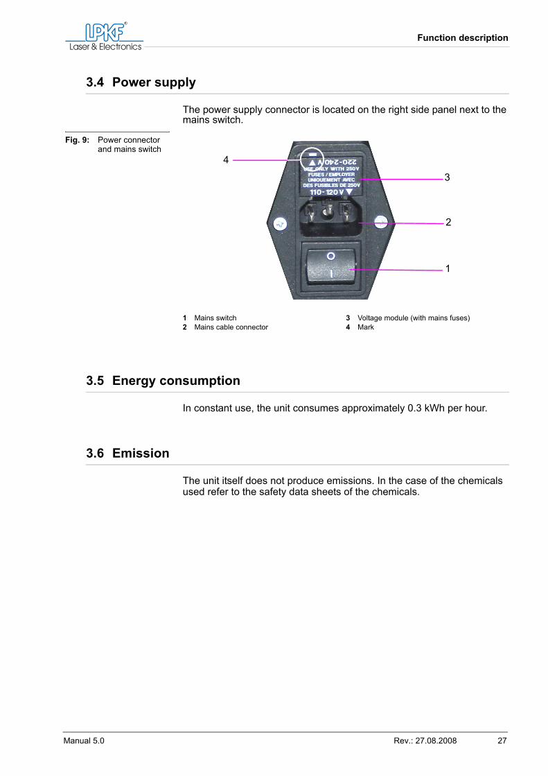
3.4 Power supply
The power supply connector is located on the right side panel next to the mains switch.
3.5 Energy consumption
In constant use, the unit consumes approximately 0.3 kWh per hour.
3.6 Emission
The unit itself does not produce emissions. In the case of the chemicals used refer to the safety data sheets of the chemicals.
Fig. 9: Power connector and mains switch
1 Mains switch2 Mains cable connector
3 Voltage module (with mains fuses)4 Mark
1
2
3
4

Emission
28 MiniContac RS
Transport and storage
Manual 5.0 Rev.: 27.08.2008 29
4. Transport and storage
4.1 Transport
4.2 Storage
Store the unit in a frost-free and dry place.
WARNING
Lifting hazard — heavy object.The unit weighs approx. 47 kg. Single person lifting could cause muscle strain or back injury.› Always have two persons of adequate physical strength lift,
move, or install the unit.
CAUTION
Risk of breakage!Unit can be damaged when transported.› Transport the unit only proper packaging.› Transport utilities must be designed for loads greater than
70 kg.

Storage
30 MiniContac RS
Installation and preparing operation
Manual 5.0 Rev.: 27.08.2008 31
5. Installation and preparing operation
5.1 Safety measures before installing
Mains power (230/115 V) must be supplied via a Residual Current Device (RCD, aka GFI, Ground Fault Interrupter).A sufficiently large, horizontal, and firm workspace must be provided for the MiniContac RS unit.
5.2 Unpacking, disposal of packing materials
Note: Unpack the unit carefully and store the packing material. This facilitates safe packing and shipping of the unit if the unit has to be serviced.
Unpacking the unit
1. Lift off the the lid of the transport box.2. Remove the enclosed smaller components from the box.3. Remove the collecting tank from the box.4. With the aid of at least one more person, lift the unit out of the box.5. Store the packing material for later transport of the unit.[ ] The unit is unpacked and can now be set up.
5.3 Setting up and putting into service
WARNING
Lifting hazard — heavy object.The unit weighs approx. 47 kg. Single person lifting could cause muscle strain or back injury.› Always have two persons of adequate physical strength lift,
move, or install the unit.
CAUTION
Risk of damage!The foam packaging of the heating element can melt and contam-inate the unit.› The foam packaging of the heating element must be removed
before putting the MiniContac RS unit into service!
Setting up and putting into service
32 MiniContac RS
5.3.1 Assembling
Installing the unit
1. Transfer the unit and its accessories to a firm, horizontal and suffi-ciently large workspace.
2. Place the collecting tank on the workspace surface.Note: When setting up the unit bear in mind that you need additional ba-sins or a sink (not included) for rinsing the circuit boards.
3. With the aid of at least one more person set the unit into the collect-ing tank.
[ ] The unit is set up and you can now mount the copper anodes.
Tip: The unit and the chemical baths must be initialised, which takes approx. 300 minutes, before producing the first through-plated circuit board. Please bear this lead time in mind when putting the unit into service.
WARNING
Lifting hazard — heavy object.The unit weighs approx. 47 kg. Single person lifting could cause muscle strain or back injury.› Always have two persons of adequate physical strength lift,
move, or install the unit.
Installation and preparing operation
Manual 5.0 Rev.: 27.08.2008 33
Mounting the copper anodes
The phosphated copper anodes supplied with the unit have to be installed in tank 4. Proceed as follows:
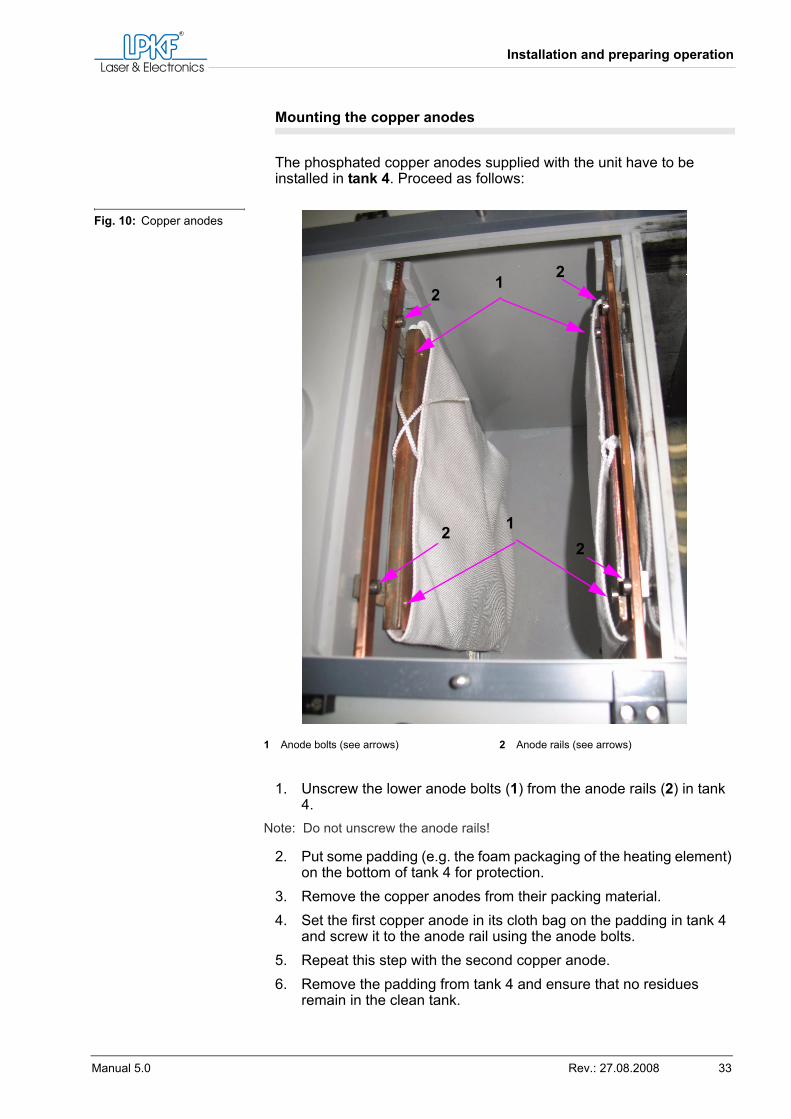
1. Unscrew the lower anode bolts (1) from the anode rails (2) in tank 4.
Note: Do not unscrew the anode rails!
2. Put some padding (e.g. the foam packaging of the heating element) on the bottom of tank 4 for protection.
3. Remove the copper anodes from their packing material.4. Set the first copper anode in its cloth bag on the padding in tank 4
and screw it to the anode rail using the anode bolts.5. Repeat this step with the second copper anode.6. Remove the padding from tank 4 and ensure that no residues
remain in the clean tank.
Fig. 10: Copper anodes
1 Anode bolts (see arrows) 2 Anode rails (see arrows)
1
12
22
2
Setting up and putting into service
34 MiniContac RS
7. Tie a knot of the laces of the anode bags directly above the copper anodes and place the lace ends into the anode bags.
[ ] The copper anodes are mounted you can now insert the thermometer.
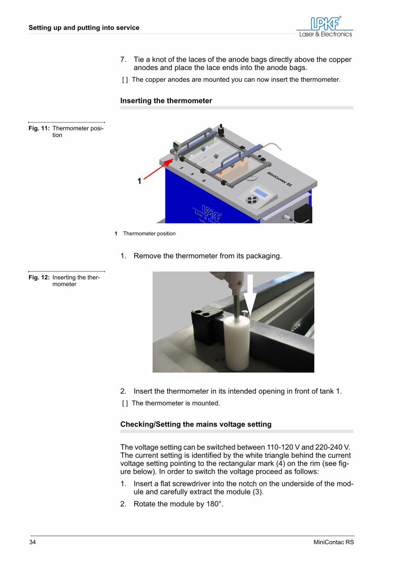
Inserting the thermometer
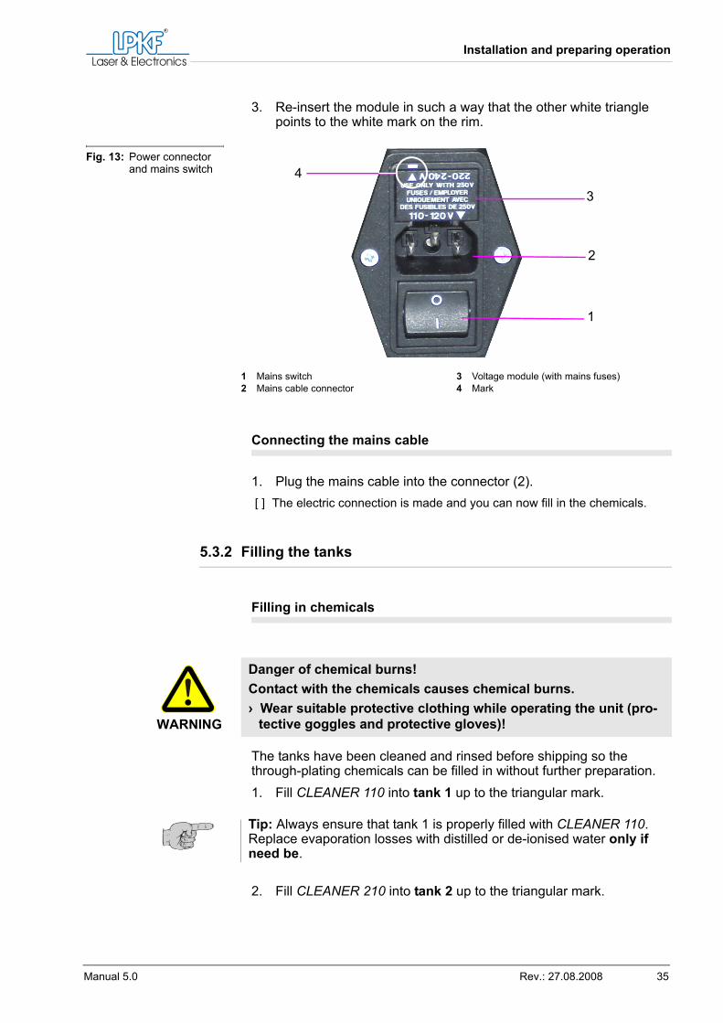
1. Remove the thermometer from its packaging.
2. Insert the thermometer in its intended opening in front of tank 1.[ ] The thermometer is mounted.
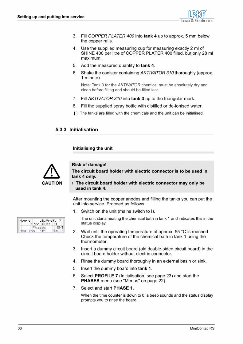
Checking/Setting the mains voltage setting
The voltage setting can be switched between 110-120 V and 220-240 V. The current setting is identified by the white triangle behind the current voltage setting pointing to the rectangular mark (4) on the rim (see fig-ure below). In order to switch the voltage proceed as follows:1. Insert a flat screwdriver into the notch on the underside of the mod-
ule and carefully extract the module (3).2. Rotate the module by 180°.
Fig. 11: Thermometer posi-tion
1 Thermometer position
1
Fig. 12: Inserting the ther-mometer
Installation and preparing operation
Manual 5.0 Rev.: 27.08.2008 35
3. Re-insert the module in such a way that the other white triangle points to the white mark on the rim.
Connecting the mains cable
1. Plug the mains cable into the connector (2).[ ] The electric connection is made and you can now fill in the chemicals.
5.3.2 Filling the tanks
Filling in chemicals
The tanks have been cleaned and rinsed before shipping so the through-plating chemicals can be filled in without further preparation.1. Fill CLEANER 110 into tank 1 up to the triangular mark.
2. Fill CLEANER 210 into tank 2 up to the triangular mark.
Fig. 13: Power connector and mains switch
1 Mains switch2 Mains cable connector
3 Voltage module (with mains fuses)4 Mark
1
2
3
4
WARNING
Danger of chemical burns!Contact with the chemicals causes chemical burns.› Wear suitable protective clothing while operating the unit (pro-
tective goggles and protective gloves)!
Tip: Always ensure that tank 1 is properly filled with CLEANER 110. Replace evaporation losses with distilled or de-ionised water only if need be.
Setting up and putting into service
36 MiniContac RS
3. Fill COPPER PLATER 400 into tank 4 up to approx. 5 mm below the copper rails.
4. Use the supplied measuring cup for measuring exactly 2 ml of SHINE 400 per litre of COPPER PLATER 400 filled, but only 28 ml maximum.
5. Add the measured quantity to tank 4.6. Shake the canister containing AKTIVATOR 310 thoroughly (approx.
1 minute).Note: Tank 3 for the AKTIVATOR chemical must be absolutely dry and clean before filling and should be filled last.
7. Fill AKTIVATOR 310 into tank 3 up to the triangular mark.8. Fill the supplied spray bottle with distilled or de-ionised water.[ ] The tanks are filled with the chemicals and the unit can be initialised.
5.3.3 Initialisation
Initialising the unit
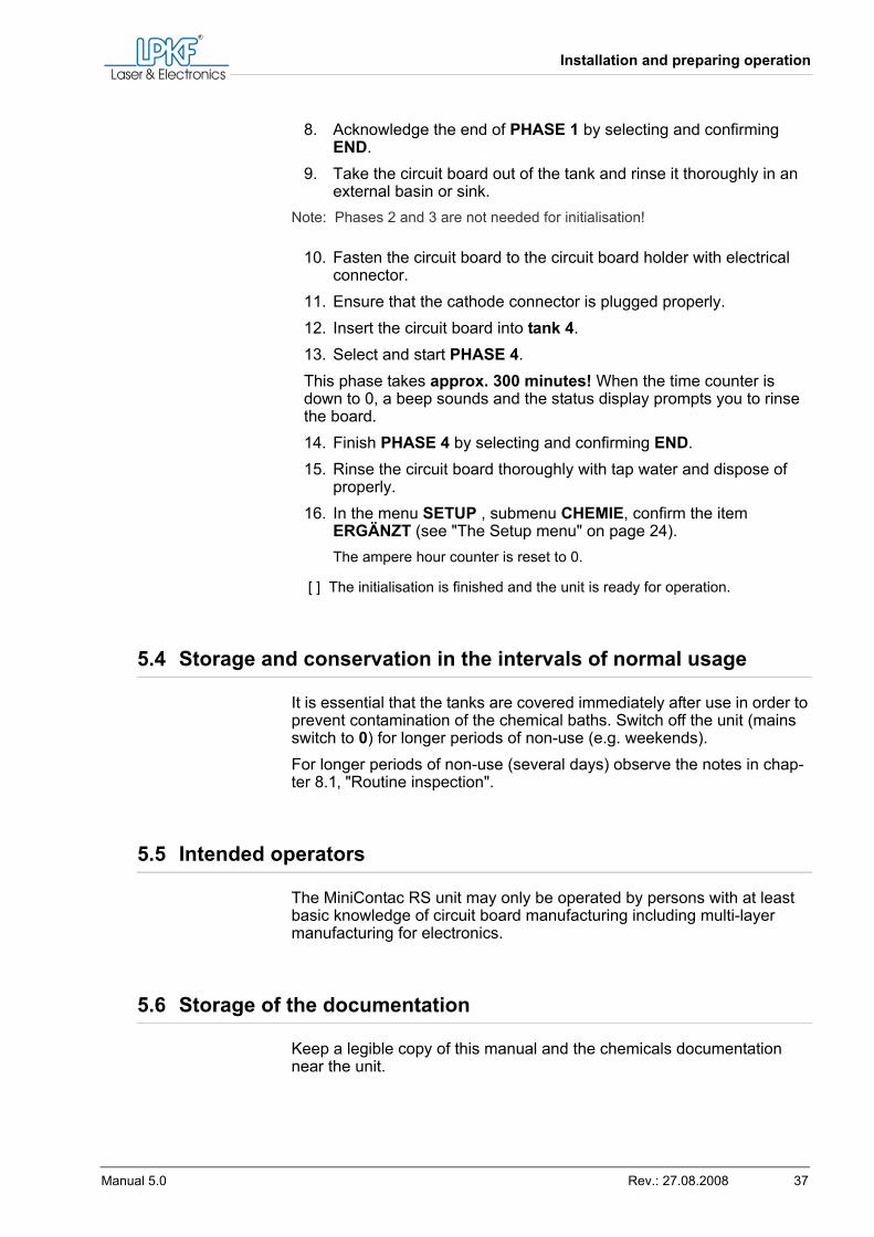
After mounting the copper anodes and filling the tanks you can put the unit into service. Proceed as follows:1. Switch on the unit (mains switch to I).
The unit starts heating the chemical bath in tank 1 and indicates this in the status display.
2. Wait until the operating temperature of approx. 55 °C is reached. Check the temperature of the chemical bath in tank 1 using the thermometer.
3. Insert a dummy circuit board (old double-sided circuit board) in the circuit board holder without electric connector.
4. Rinse the dummy board thoroughly in an external basin or sink.5. Insert the dummy board into tank 1.6. Select PROFILE 7 (Initialisation, see page 23) and start the
PHASES menu (see "Menus" on page 22).7. Select and start PHASE 1.
When the time counter is down to 0, a beep sounds and the status display prompts you to rinse the board.
CAUTION
Risk of damage!The circuit board holder with electric connector is to be used in tank 4 only.› The circuit board holder with electric connector may only be
used in tank 4.
Installation and preparing operation
Manual 5.0 Rev.: 27.08.2008 37
8. Acknowledge the end of PHASE 1 by selecting and confirming END.
9. Take the circuit board out of the tank and rinse it thoroughly in an external basin or sink.
Note: Phases 2 and 3 are not needed for initialisation!
10. Fasten the circuit board to the circuit board holder with electrical connector.
11. Ensure that the cathode connector is plugged properly.12. Insert the circuit board into tank 4.13. Select and start PHASE 4.This phase takes approx. 300 minutes! When the time counter is down to 0, a beep sounds and the status display prompts you to rinse the board.14. Finish PHASE 4 by selecting and confirming END.15. Rinse the circuit board thoroughly with tap water and dispose of
properly.16. In the menu SETUP , submenu CHEMIE, confirm the item
ERGÄNZT (see "The Setup menu" on page 24).The ampere hour counter is reset to 0.
[ ] The initialisation is finished and the unit is ready for operation.
5.4 Storage and conservation in the intervals of normal usage
It is essential that the tanks are covered immediately after use in order to prevent contamination of the chemical baths. Switch off the unit (mains switch to 0) for longer periods of non-use (e.g. weekends).For longer periods of non-use (several days) observe the notes in chap-ter 8.1‚ "Routine inspection".
5.5 Intended operators
The MiniContac RS unit may only be operated by persons with at least basic knowledge of circuit board manufacturing including multi-layer manufacturing for electronics.
5.6 Storage of the documentation
Keep a legible copy of this manual and the chemicals documentation near the unit.

Storage of the documentation
38 MiniContac RS
Operation
Manual 5.0 Rev.: 27.08.2008 39
6. Operation
The circuit board should be drilled only with carbide drills that are suitable for the board material and are in mint condition. Comply with the drill parameters found in the drill's manual or the tool libraries of BoardMaster.Preferably use FR4 with a copper layer of 5 or 9 µm (depending on avail-ability). As this material has a protective copper film, rinsing suffices to clean the drilled holes.When using base material without protective film, e.g. FR4 18/18 µm, you need to deburr the drilled board and brush or scrub the surface, e.g. with a non-woven synthetic (do not use steel wool). Rinse the circuit board thoroughly, especially the holes.Before processing the circuit board select the profile suitable for your requirements. If you should use board material of dimensions other than 9 x 12 “, you will have to edit the profile according to the board dimen-sions employed (see "The Profiles menu" on page 23).
6.1 Changing settings
Changing profile
In order to change the individual menu items proceed as follows (exam-ple: T bath 2 in PROFILES):1. Select the menu item to be changed (see "Menu levels" on
page 22).2. Edit the time setting as follows:
WARNING
Danger of chemical burns!Contact with the chemicals can cause chemical burns.› Wear suitable protective clothing while operating the unit (pro-
tective goggles and protective gloves)!
CAUTION
Chemicals can be ruined!Contaminants can cause chemical reactions and degrade the through-plating or ruin the respective chemical bath.› Never use oil-contaminated compressed air for blow-off!
CAUTION
Chemicals can be ruined!The chemical baths can be ruined by carry-over from the previous baths.› Use the supplied adhesive tape to seal the edges of multi-layer
circuit boards to prevent carry-over.
Changing settings
40 MiniContac RS
3. Select the digit using the key.4. Choose a number by pressing the or key.
Note: You can abort by pressing the key (corresponds to ESC).
5. Press the key several times to move the cursor to the last entry position and press the key one more time (corresponds to ENT).The value entered is stored.
6. Press the key (ESC) as many times as needed to reach the main menu.
[ ] The change is completed.
Note: If any problem arises contact the LPKF customer service.
Calculating the current
When using circuit boards of dimensions other than provided in the pro-files, the current has to be recalculated and the profile has to be edited accordingly (see "Changing settings" on page 39). The current is calcu-lated as follows:1. Calculate the circuit board surface w x l in mm2.
Operation
Manual 5.0 Rev.: 27.08.2008 41
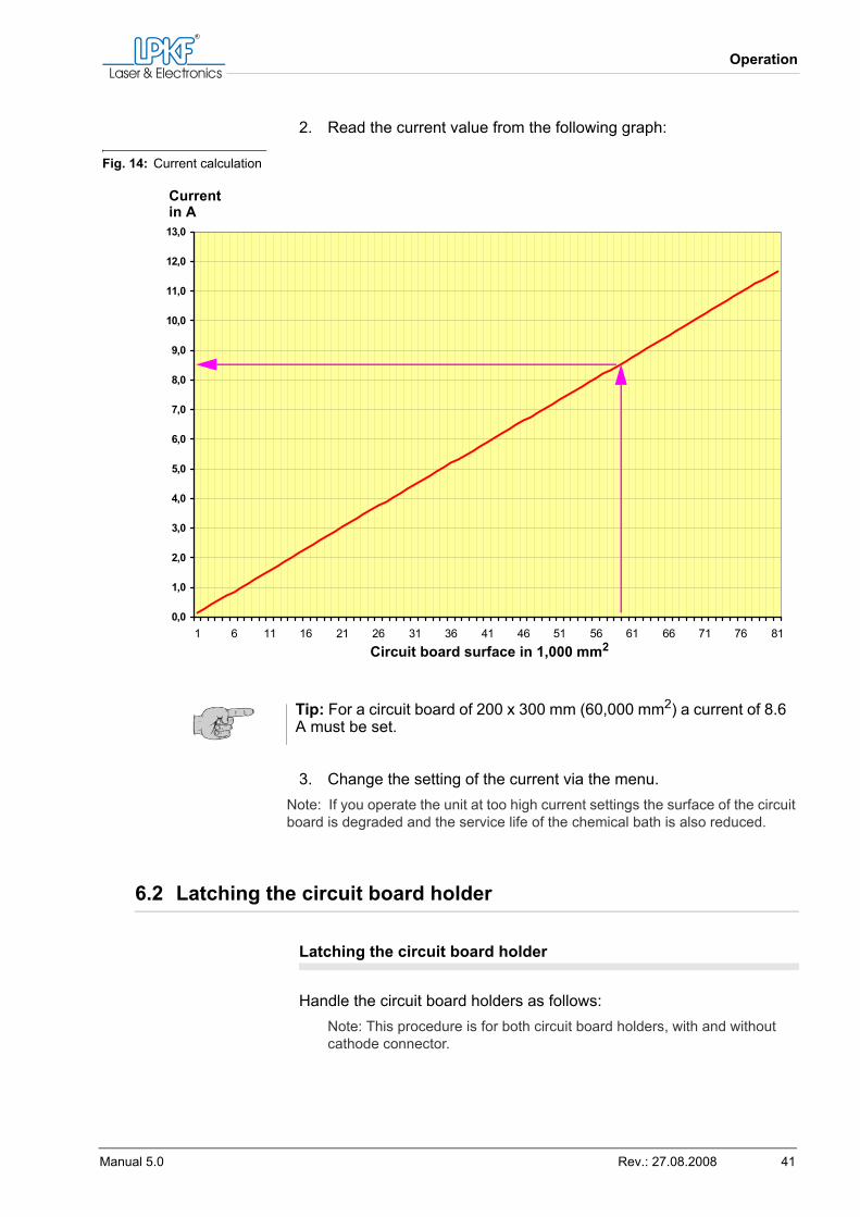
2. Read the current value from the following graph:
3. Change the setting of the current via the menu.Note: If you operate the unit at too high current settings the surface of the circuit board is degraded and the service life of the chemical bath is also reduced.
6.2 Latching the circuit board holder
Latching the circuit board holder
Handle the circuit board holders as follows:Note: This procedure is for both circuit board holders, with and without cathode connector.
Fig. 14: Current calculation
Tip: For a circuit board of 200 x 300 mm (60,000 mm2) a current of 8.6 A must be set.
0,0
1,0
2,0
3,0
4,0
5,0
6,0
7,0
8,0
9,0
10,0
11,0
12,0
13,0
1 6 11 16 21 26 31 36 41 46 51 56 61 66 71 76 81
Currentin A
Circuit board surface in 1,000 mm2
Latching the circuit board holder
42 MiniContac RS
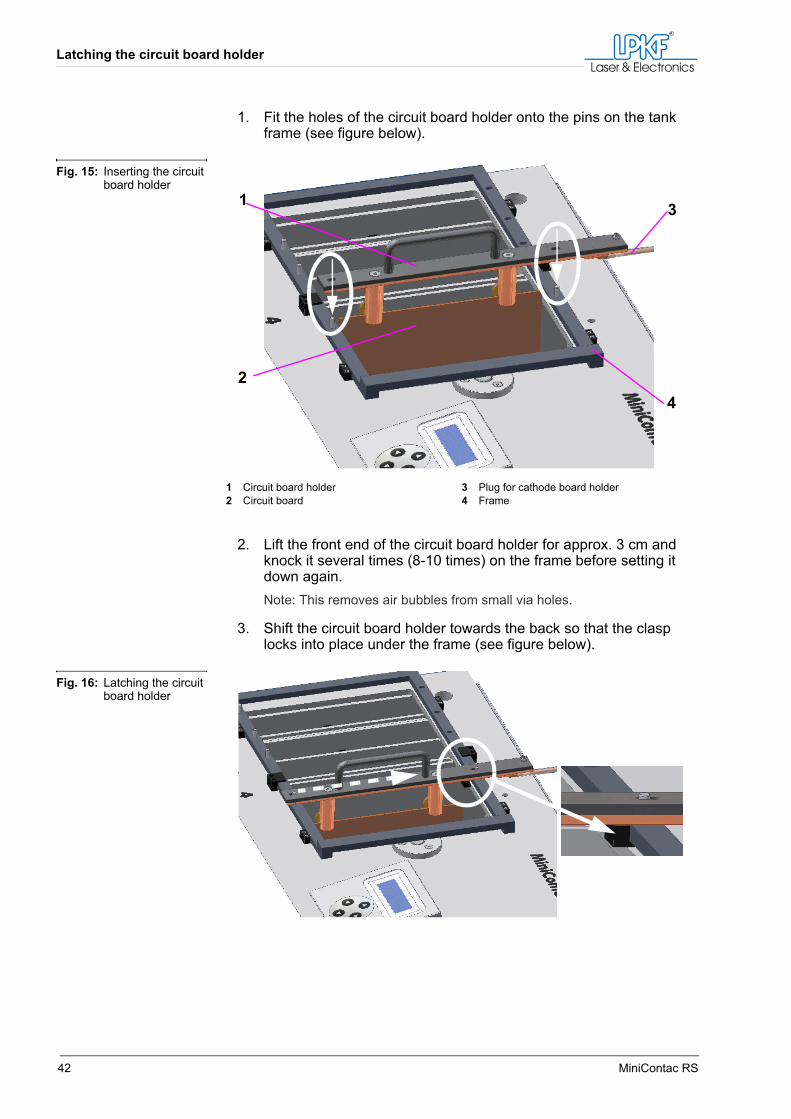
1. Fit the holes of the circuit board holder onto the pins on the tank frame (see figure below).
2. Lift the front end of the circuit board holder for approx. 3 cm and knock it several times (8-10 times) on the frame before setting it down again.Note: This removes air bubbles from small via holes.
3. Shift the circuit board holder towards the back so that the clasp locks into place under the frame (see figure below).
Fig. 15: Inserting the circuit board holder
1 Circuit board holder2 Circuit board
3 Plug for cathode board holder4 Frame
1
2
3
4
Fig. 16: Latching the circuit board holder
Operation
Manual 5.0 Rev.: 27.08.2008 43
6.3 The through-plating process
Note: Ensure that the room temperature is in the range of 18-25 °C as the chemical baths do not work outside this range.
Note: Use the supplied adhesive tape to seal the edges of multi-layer circuit boards to prevent carry-over.
6.3.1 Work prerequisites
Ensure that:
• The unit is switched on (mains switch to I).• Bath 1 is heated (operation temperature of approx. 55 °C is displayed
on the digital thermometer).
WARNING
Danger of chemical burns!Contact with the chemicals can cause chemical burns.› Wear suitable protective clothing while operating the unit (pro-
tective goggles and protective gloves)!
Tip: Depending on tank temperature, current, circuit board size and condition of the chemicals, an average of 0.1 - 0.2 µm copper are deposited per minute. Thus, approx. 6 - 12 µm copper are deposited per hour. Please note that these values are only estimates for the attainable copper layer thickness that can vary with a unit for labora-tory use such as the MiniContac RS unit.If you need exact values for the copper thickness in the via holes it is advisable to manufacture several test circuit boards and use micro-graphs to measure the actual thickness.Once you have found the parameters for the desired thickness you can start through-plating the real circuit board.We recommend using the parameters specified by us to obtain satis-factory through-plating results.
The through-plating process
44 MiniContac RS
6.3.2 Work process
Fastening the circuit board
1. Fasten the base material to the circuit board holder.2. Rinse the circuit board thoroughly in an external basin or sink.
Phase 1: Degreasing the circuit board
1. Insert the circuit board with several knocking movements (see "Latching the circuit board holder" on page 41) into tank 1.
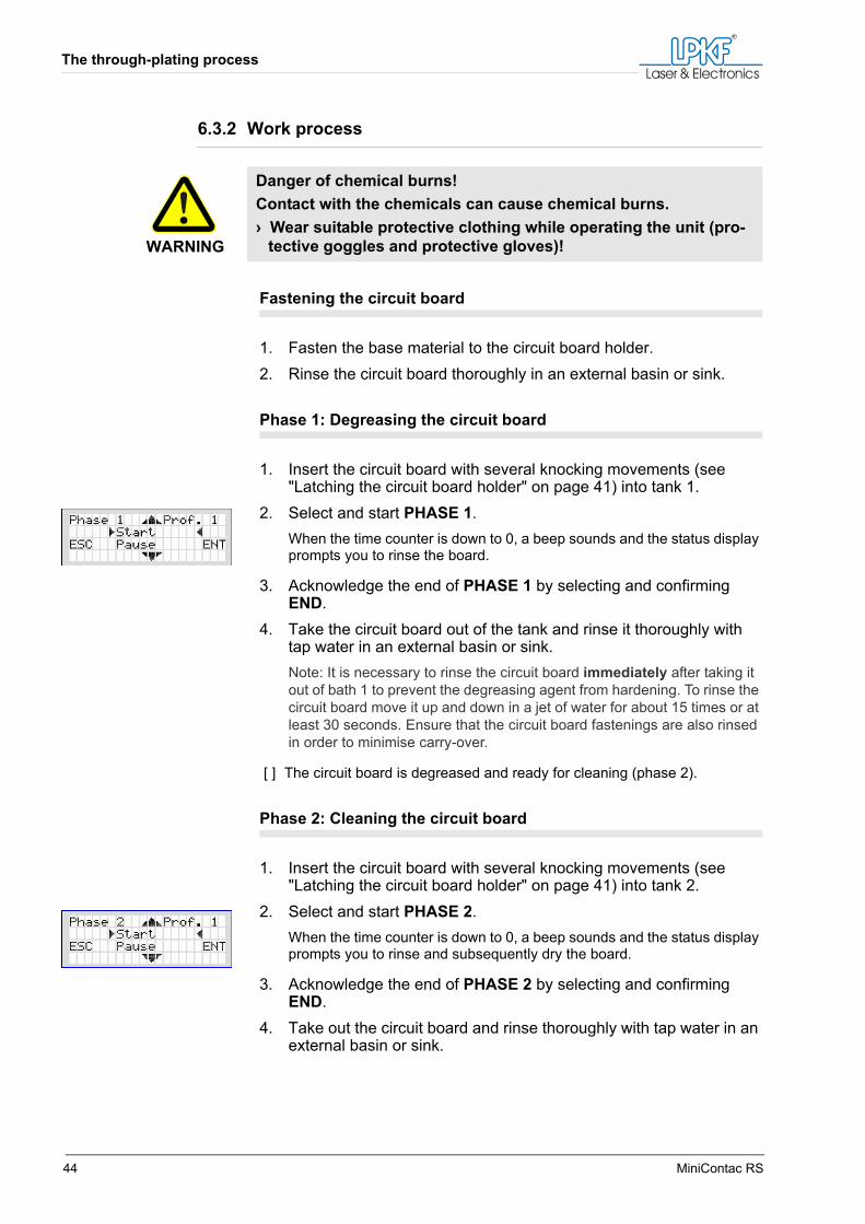
2. Select and start PHASE 1.When the time counter is down to 0, a beep sounds and the status display prompts you to rinse the board.
3. Acknowledge the end of PHASE 1 by selecting and confirming END.
4. Take the circuit board out of the tank and rinse it thoroughly with tap water in an external basin or sink.Note: It is necessary to rinse the circuit board immediately after taking it out of bath 1 to prevent the degreasing agent from hardening. To rinse the circuit board move it up and down in a jet of water for about 15 times or at least 30 seconds. Ensure that the circuit board fastenings are also rinsed in order to minimise carry-over.
[ ] The circuit board is degreased and ready for cleaning (phase 2).
Phase 2: Cleaning the circuit board
1. Insert the circuit board with several knocking movements (see "Latching the circuit board holder" on page 41) into tank 2.
2. Select and start PHASE 2.When the time counter is down to 0, a beep sounds and the status display prompts you to rinse and subsequently dry the board.
3. Acknowledge the end of PHASE 2 by selecting and confirming END.
4. Take out the circuit board and rinse thoroughly with tap water in an external basin or sink.
WARNING
Danger of chemical burns!Contact with the chemicals can cause chemical burns.› Wear suitable protective clothing while operating the unit (pro-
tective goggles and protective gloves)!
Operation
Manual 5.0 Rev.: 27.08.2008 45
5. Using the spray bottle supplied with the unit, rinse the circuit board with distilled or de-ionised water. Make sure that the via holes are also rinsed thoroughly in this step.Note: Take special care rinsing the circuit board otherwise the AKTIVA-TOR chemical is ruined by trace elements of the tap water (chlorine, cal-cium carbonate etc.) and has to be replaced completely.
6. Blow off the circuit board with oil-free compressed air until the water is removed from the holes.
Note: The circuit board does not have to be completely dry but make sure that the holes are completely cleared for the next phase. Too much water dilutes the AKTIVATOR chemical!
7. Cover tanks 1 and 2 to avoid evaporation losses.Note: Keep tank 4 covered as well.
[ ] The circuit board is cleaned and ready for activation (phase 3).
Phase 3: Activating the circuit board
1. Insert the circuit board with several knocking movements (see "Latching the circuit board holder" on page 41) into tank 3.
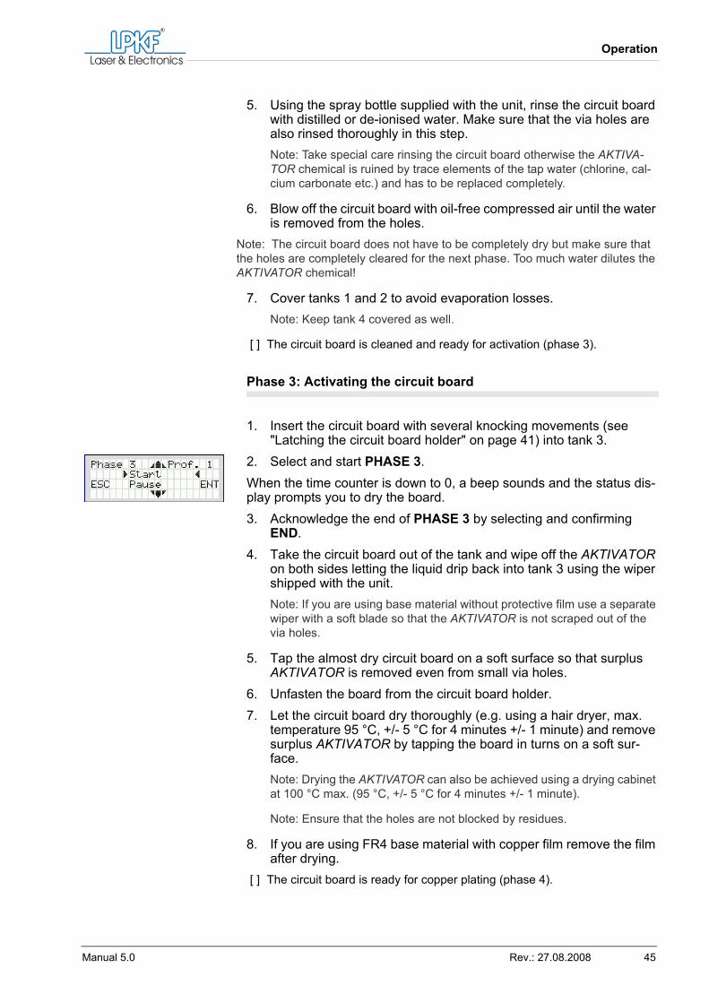
2. Select and start PHASE 3.When the time counter is down to 0, a beep sounds and the status dis-play prompts you to dry the board.3. Acknowledge the end of PHASE 3 by selecting and confirming
END.4. Take the circuit board out of the tank and wipe off the AKTIVATOR
on both sides letting the liquid drip back into tank 3 using the wiper shipped with the unit.Note: If you are using base material without protective film use a separate wiper with a soft blade so that the AKTIVATOR is not scraped out of the via holes.
5. Tap the almost dry circuit board on a soft surface so that surplus AKTIVATOR is removed even from small via holes.
6. Unfasten the board from the circuit board holder.7. Let the circuit board dry thoroughly (e.g. using a hair dryer, max.
temperature 95 °C, +/- 5 °C for 4 minutes +/- 1 minute) and remove surplus AKTIVATOR by tapping the board in turns on a soft sur-face.Note: Drying the AKTIVATOR can also be achieved using a drying cabinet at 100 °C max. (95 °C, +/- 5 °C for 4 minutes +/- 1 minute).
Note: Ensure that the holes are not blocked by residues.
8. If you are using FR4 base material with copper film remove the film after drying.
[ ] The circuit board is ready for copper plating (phase 4).
The through-plating process
46 MiniContac RS
Phase 4: Preparing the copper plating
1. Remove any oxide layers on the circuit board holder with electrical connector using sandpaper (copper gleam must be visible at the bolt and the flat surfaces).
2. Fasten the circuit board to the circuit board holder with electrical connector.
3. Ensure that the cathode connector is plugged properly.
Phase 4: Starting copper plating
1. Insert the circuit board with several knocking movements (see "Latching the circuit board holder" on page 41) into tank 4.
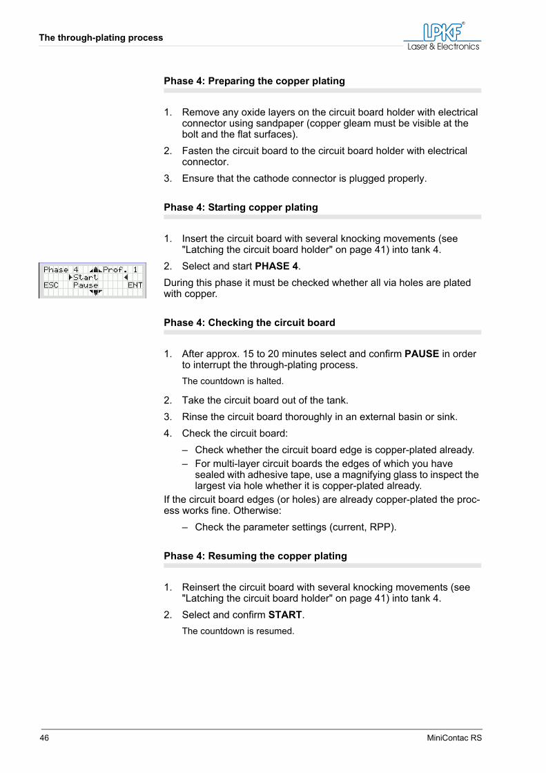
2. Select and start PHASE 4.During this phase it must be checked whether all via holes are plated with copper.
Phase 4: Checking the circuit board
1. After approx. 15 to 20 minutes select and confirm PAUSE in order to interrupt the through-plating process.The countdown is halted.
2. Take the circuit board out of the tank.3. Rinse the circuit board thoroughly in an external basin or sink.4. Check the circuit board:
– Check whether the circuit board edge is copper-plated already.– For multi-layer circuit boards the edges of which you have
sealed with adhesive tape, use a magnifying glass to inspect the largest via hole whether it is copper-plated already.
If the circuit board edges (or holes) are already copper-plated the proc-ess works fine. Otherwise:
– Check the parameter settings (current, RPP).
Phase 4: Resuming the copper plating
1. Reinsert the circuit board with several knocking movements (see "Latching the circuit board holder" on page 41) into tank 4.
2. Select and confirm START.The countdown is resumed.
Operation
Manual 5.0 Rev.: 27.08.2008 47
When half the time is over a beep is sounded and you are prompted to turn around the circuit board.3. Take the circuit board holder with the circuit board out of the tank,
turn it 180 °, and re-insert it with several knocking movements into the tank (see "Latching the circuit board holder" on page 41).
4. Select and confirm START.When the time counter is down to 0, a beep sounds and the status display prompts you to rinse and subsequently dry the board.
5. Acknowledge the end of PHASE 4 by selecting and confirming END.
PHASE 4 can be repeated as often as needed by pressing the key.
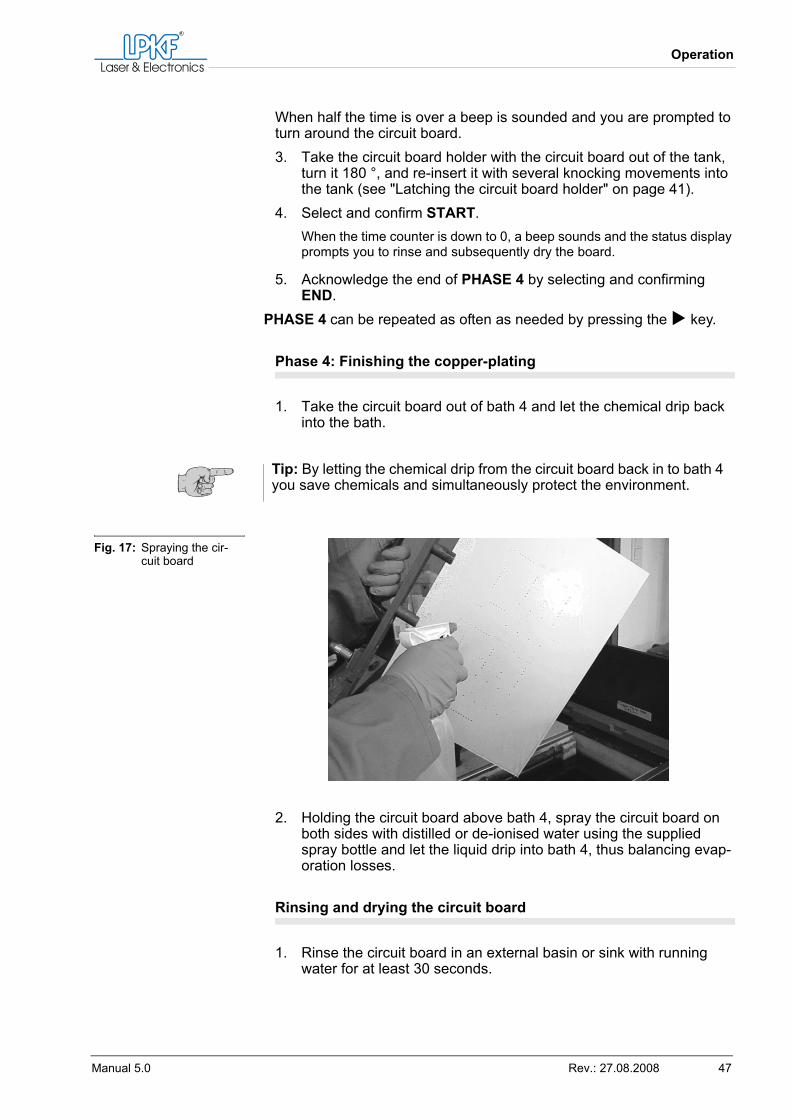
Phase 4: Finishing the copper-plating
1. Take the circuit board out of bath 4 and let the chemical drip back into the bath.
2. Holding the circuit board above bath 4, spray the circuit board on both sides with distilled or de-ionised water using the supplied spray bottle and let the liquid drip into bath 4, thus balancing evap-oration losses.
Rinsing and drying the circuit board
1. Rinse the circuit board in an external basin or sink with running water for at least 30 seconds.
Tip: By letting the chemical drip from the circuit board back in to bath 4 you save chemicals and simultaneously protect the environment.
Fig. 17: Spraying the cir-cuit board
The through-plating process
48 MiniContac RS
2. Blow off the circuit board with oil-free compressed air.3. Dry the circuit board quickly, using warm air if possible (e.g. with a
hair dryer but not in a drying cabinet).Note: This should be done as quickly as possible to prevent the copper from oxidising.
[ ] The through-plating of the circuit board is finished and the board can be processed further.
WARNING
Danger of chemical burns!If not rinsed properly, the operator can touch residual acid remaining on the circuit board.› Do not let the rinse time be less than 30 seconds.
CAUTION
Environmental hazard!The contaminant load of the rinse water will be exceeded if not thoroughly diluted.› Do not let the rinse time be less than 30 seconds.
Operation
Manual 5.0 Rev.: 27.08.2008 49
6.4 Process sequence
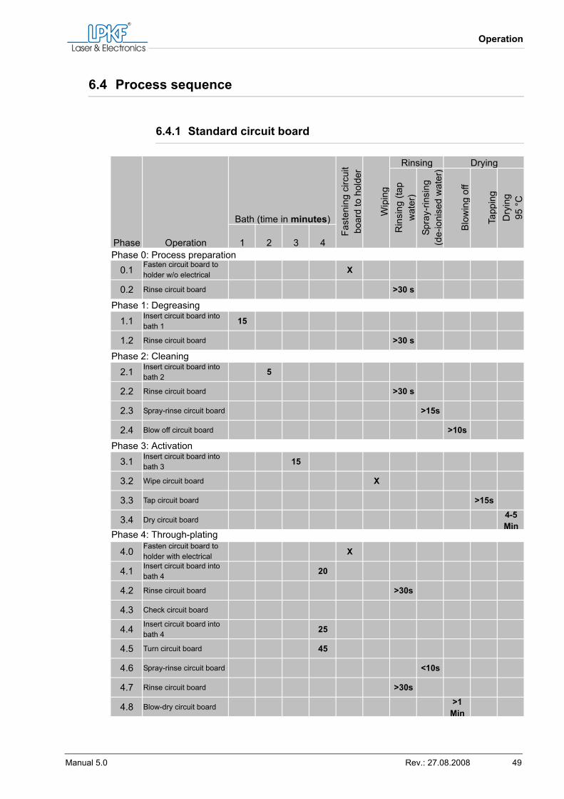
6.4.1 Standard circuit board
Phase Operation
Bath (time in minutes)
Fast
enin
g ci
rcui
t bo
ard
to h
olde
r
Wip
ing
Rinsing Drying
Rin
sing
(tap
w
ater
)Sp
ray-
rinsi
ng(d
e-io
nise
d w
ater
)
Blo
win
g of
f
Tapp
ing
Dry
ing
95 °
C
1 2 3 4Phase 0: Process preparation
0.1 Fasten circuit board to holder w/o electrical X
0.2 Rinse circuit board >30 s
Phase 1: Degreasing1.1 Insert circuit board into
bath 1 15
1.2 Rinse circuit board >30 s
Phase 2: Cleaning2.1 Insert circuit board into
bath 2 5
2.2 Rinse circuit board >30 s
2.3 Spray-rinse circuit board >15s
2.4 Blow off circuit board >10s
Phase 3: Activation3.1 Insert circuit board into
bath 3 15
3.2 Wipe circuit board X
3.3 Tap circuit board >15s
3.4 Dry circuit board 4-5 Min
Phase 4: Through-plating
4.0 Fasten circuit board to holder with electrical X
4.1 Insert circuit board into bath 4 20
4.2 Rinse circuit board >30s
4.3 Check circuit board
4.4 Insert circuit board into bath 4 25
4.5 Turn circuit board 45
4.6 Spray-rinse circuit board <10s
4.7 Rinse circuit board >30s
4.8 Blow-dry circuit board >1 Min
Process sequence
50 MiniContac RS
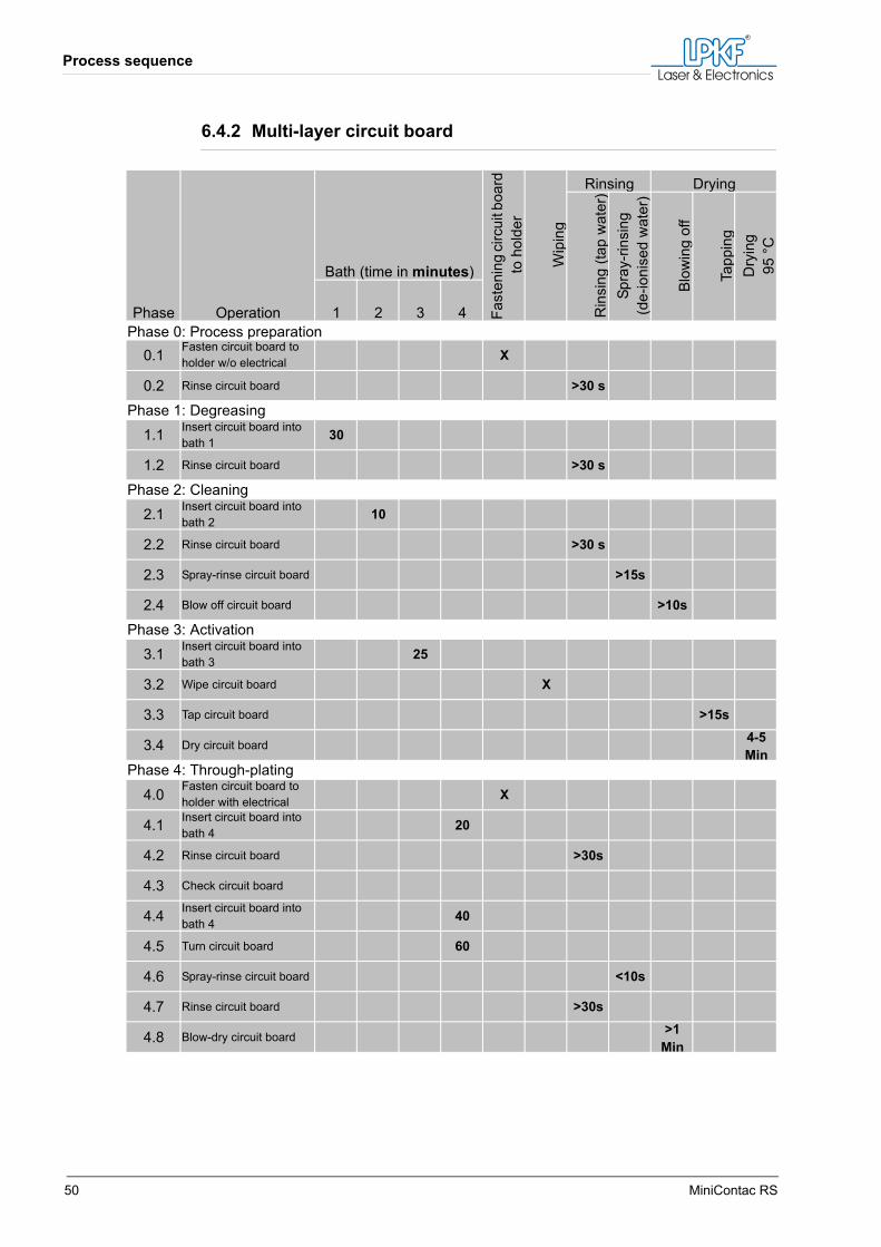
6.4.2 Multi-layer circuit board
Phase Operation
Bath (time in minutes)
Fast
enin
g ci
rcui
t boa
rd
to h
olde
r
Wip
ing
Rinsing Drying
Rin
sing
(tap
wat
er)
Spra
y-rin
sing
(de-
ioni
sed
wat
er)
Blo
win
g of
f
Tapp
ing
Dry
ing
95 °
C
1 2 3 4Phase 0: Process preparation
0.1 Fasten circuit board to holder w/o electrical X
0.2 Rinse circuit board >30 s
Phase 1: Degreasing1.1 Insert circuit board into
bath 1 30
1.2 Rinse circuit board >30 s
Phase 2: Cleaning2.1 Insert circuit board into
bath 2 10
2.2 Rinse circuit board >30 s
2.3 Spray-rinse circuit board >15s
2.4 Blow off circuit board >10s
Phase 3: Activation3.1 Insert circuit board into
bath 3 25
3.2 Wipe circuit board X
3.3 Tap circuit board >15s
3.4 Dry circuit board 4-5 Min
Phase 4: Through-plating
4.0 Fasten circuit board to holder with electrical X
4.1 Insert circuit board into bath 4 20
4.2 Rinse circuit board >30s
4.3 Check circuit board
4.4 Insert circuit board into bath 4 40
4.5 Turn circuit board 60
4.6 Spray-rinse circuit board <10s
4.7 Rinse circuit board >30s
4.8 Blow-dry circuit board >1 Min
Operation
Manual 5.0 Rev.: 27.08.2008 51
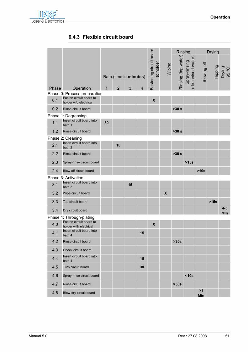
6.4.3 Flexible circuit board
Phase Operation
Bath (time in minutes)
Fast
enin
g ci
rcui
t boa
rd
to h
olde
r
Wip
ing
Rinsing Drying
Rin
sing
(tap
wat
er)
Spra
y-rin
sing
(de-
ioni
sed
wat
er)
Blo
win
g of
f
Tapp
ing
Dry
ing
95 °
C
1 2 3 4Phase 0: Process preparation
0.1 Fasten circuit board to holder w/o electrical X
0.2 Rinse circuit board >30 s
Phase 1: Degreasing1.1 Insert circuit board into
bath 1 30
1.2 Rinse circuit board >30 s
Phase 2: Cleaning2.1 Insert circuit board into
bath 2 10
2.2 Rinse circuit board >30 s
2.3 Spray-rinse circuit board >15s
2.4 Blow off circuit board >10s
Phase 3: Activation3.1 Insert circuit board into
bath 3 15
3.2 Wipe circuit board X
3.3 Tap circuit board >15s
3.4 Dry circuit board 4-5 Min
Phase 4: Through-plating
4.0 Fasten circuit board to holder with electrical X
4.1 Insert circuit board into bath 4 15
4.2 Rinse circuit board >30s
4.3 Check circuit board
4.4 Insert circuit board into bath 4 15
4.5 Turn circuit board 30
4.6 Spray-rinse circuit board <10s
4.7 Rinse circuit board >30s
4.8 Blow-dry circuit board >1 Min
Waste Disposal
52 MiniContac RS
6.5 Waste disposal
Do not let spilled chemicals reach the sewer system.The rinse water of the through-plating process can be disposed of via the sewer system (see appendix).Never pour spent chemicals down the drain, fill into canisters for disposal and dispose of at a certified chemical treatment plant.Refer to the documentation of the chemicals for the appropriate method of disposal (neutralisation, hazardous waste disposal, chemical-physical treatment).Always check and adhere to local and national regulations for the internal or external disposal of waste.Local and national regulations always take precedence over our recom-mendations.
Troubleshooting
Manual 5.0 Rev.: 27.08.2008 53
7. Troubleshooting
7.1 Safety advice
7.2 Error codes
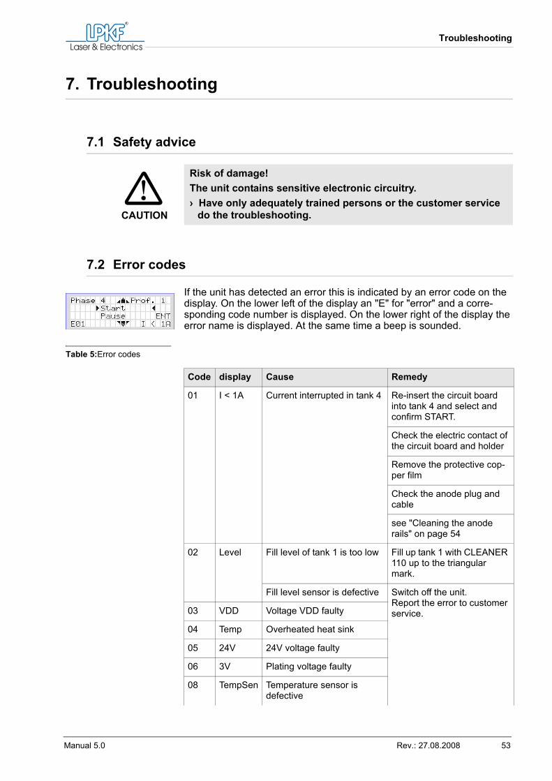
If the unit has detected an error this is indicated by an error code on the display. On the lower left of the display an "E" for "error" and a corre-sponding code number is displayed. On the lower right of the display the error name is displayed. At the same time a beep is sounded.
Table 5:Error codes
CAUTION
Risk of damage!The unit contains sensitive electronic circuitry.› Have only adequately trained persons or the customer service
do the troubleshooting.
Code display Cause Remedy
01 I < 1A Current interrupted in tank 4 Re-insert the circuit board into tank 4 and select and confirm START.
Check the electric contact of the circuit board and holder
Remove the protective cop-per film
Check the anode plug and cable
see "Cleaning the anode rails" on page 54
02 Level Fill level of tank 1 is too low Fill up tank 1 with CLEANER 110 up to the triangular mark.
Fill level sensor is defective Switch off the unit. Report the error to customer service.03 VDD Voltage VDD faulty
04 Temp Overheated heat sink
05 24V 24V voltage faulty
06 3V Plating voltage faulty
08 TempSen Temperature sensor is defective
Other fault indicators
54 MiniContac RS
7.3 Other fault indicators
Table 6:Other faults
7.4 Simple troubleshooting
7.4.1 Cleaning the anode rails
Removing deposits on the anode rails
During longer operation periods deposits of the galvanising chemical can form on the anode rails. These deposits can interrupt the electric current and thus prevent the copper-plating.1. Unplug the mains cable.2. Drain tank 4 into a clean and dry container (e.g. canister) as
described in steps 1 to 6 in "Draining the tanks" on page 60.3. Rinse tank 4 thoroughly.4. Unscrew the copper anodes (see fig. 10, "Copper anodes", on
page 33).5. Remove the anodes with the anode cloth bags.
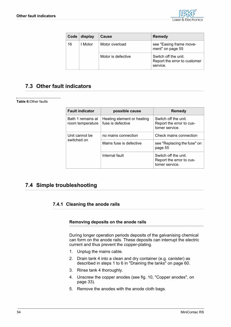
16 I Motor Motor overload see "Easing frame move-ment" on page 55
Motor is defective Switch off the unit. Report the error to customer service.
Code display Cause Remedy
Fault indicator possible cause Remedy
Bath 1 remains at room temperature
Heating element or heating fuse is defective
Switch off the unit. Report the error to cus-tomer service.
Unit cannot be switched on
no mains connection Check mains connection
Mains fuse is defective see "Replacing the fuse" on page 55
Internal fault Switch off the unit. Report the error to cus-tomer service.
Troubleshooting
Manual 5.0 Rev.: 27.08.2008 55
6. Rinse or replace the anode bags and rinse and scrub the anodes clean with a plastic brush.
7. Brush off the deposits on the anode rails towards the bottom of the tank using a plastic brush.
8. Carefully polish the anode rails around the threaded holes on both sides using sandpaper.
9. Rinse the tank thoroughly using tap water.10. Set the copper anodes complete with their cloth bags into tank 4
and screw them to the anode rails using the anode bolts.11. Let the rinse water drain completely and dispose of via the sewer
system.12. Seal the tube with the stopper and re-insert it back into the clamp
rail.13. Pour the drained chemical through a fluted filter (alternatively use
several nested paper coffee filters) into another clean and dry con-tainer (e.g. a canister).
14. Pour the filtered chemical back into the tank.[ ] The deposits on the anode rails are removed.
7.4.2 Easing frame movement
Easing frame movement
After a long time of operation it can happen that the frame seizes or becomes sluggish and thus overloads the motor.1. Unplug the mains cable.2. Loosen the guidance blocks of the frame.3. Re-fasten the guidance blocks so that the frame can be easily
moved.[ ] The frame moves easily.
7.4.3 Replacing the fuse
Replacing the fuse
The mains fuses are two glass fuses (2.5 A slow at 230 V, 5 A slow at 115 V) and are located in the voltage setting module. The fuses are located on opposite sides of the module and each fuse is mounted on the side that is nearest to the triangular mark of its corresponding volt-age.1. Disconnect the mains cable.
Customer service
56 MiniContac RS
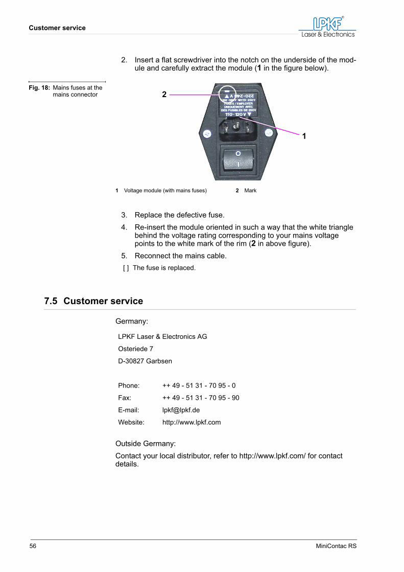
2. Insert a flat screwdriver into the notch on the underside of the mod-ule and carefully extract the module (1 in the figure below).
3. Replace the defective fuse.4. Re-insert the module oriented in such a way that the white triangle
behind the voltage rating corresponding to your mains voltage points to the white mark of the rim (2 in above figure).
5. Reconnect the mains cable.[ ] The fuse is replaced.
7.5 Customer service
Germany:
Outside Germany:Contact your local distributor, refer to http://www.lpkf.com/ for contact details.
Fig. 18: Mains fuses at the mains connector
1 Voltage module (with mains fuses) 2 Mark
1
2
LPKF Laser & Electronics AG
Osteriede 7
D-30827 Garbsen
Phone: ++ 49 - 51 31 - 70 95 - 0
Fax: ++ 49 - 51 31 - 70 95 - 90
E-mail: [email protected]
Website: http://www.lpkf.com
Service and repair
Manual 5.0 Rev.: 27.08.2008 57
8. Service and repair
8.1 Routine inspection
Tank 4 has to be inspected visually once a week for copper sulphate crystals on the walls and in the corners of the tank.These crystals have to be put back into the bath.
8.2 Service and repair by user
8.2.1 Unit
The unit itself requires no servicing.It is essential that the tanks are covered immediately after use in order to prevent contamination of the chemical baths.Carefully clean the unit regularly (depending on volume of through-plated circuit boards weekly or even daily).
8.2.2 Chemical baths
CAUTION
Chemical bath can be ruined!No copper sulphate crystals nor residues of the COPPER PLATER 400 bath may reach the neighbouring AKTIVATOR bath, the AKTI-VATOR bath would be ruined. In such a case the warranty is for-feited.› Keep the AKTIVATOR bath covered.
Tip: Never use abrasives to remove chemicals that have dripped on the unit, use a soft cloth instead. Otherwise, the unit's surface gets scratched and removal of stains is made even more difficult.
CAUTION
Risk of scrap production!Replacing or adding chemicals changes their effect.› If chemical baths have been replaced or SHINE 400 has been
added the unit should be re-initialised with a dummy circuit board.
Service and repair by user
58 MiniContac RS
Bath 1 (Degreasing)
Product: CLEANER 110Keep covered when neither tank 1 nor tank 2 is in use.Evaporation losses can be replaced with distilled or de-ionised water if need be.Replace the degreasing chemical after 3 months or when its colour has significantly changed.Note: Avoid unnecessary heating as this shortens the service life.
Bath 2 (Cleaning)
Product: CLEANER 210Keep covered when neither tank 1 nor tank 2 is in use.Evaporation losses can be replaced with distilled or de-ionised water if need be.Replace the chemical after 3 months or when its colour has significantly changed.
Bath 3 (Activation)
Product: AKTIVATOR 310Keep covered when not in use.The chemical bath is highly sensitive to contaminants and acid ions and thus requires careful handling.Traces of CLEANER 110, CLEANER 210, COPPER PLATER 400, tap water, any acidic chemicals, iron particles or similar can shortly lead to malfunction of the chemical bath. In this case it is irrelevant whether it is in use or not. If the unit is not in use the bath should be stirred thoroughly once a week.Note: After intervals of non-use (more than one day) stir the bath for 2 to 3 min-utes with a fibre glass rod or similar. If this has created foam wait until it has sub-sided before inserting a circuit board.
Replace losses only with AKTIVATOR 310 (fill up to triangular mark).
After a year at the latest, the bath has to be replaced.After replacing the chemical ensure that it is thoroughly stirred.
CAUTION
Chemical bath can be ruined!The AKTIVATOR bath is highly sensitive.› Never add water to the AKTIVATOR bath as this prevents the
through-plating from working.
Service and repair
Manual 5.0 Rev.: 27.08.2008 59
Bath 4 (Copper-plating)
Product: COPPER PLATER 400Keep covered when not in use and filter regularly (approx. every 3 weeks).Note: The service life of the tank's contents is approx. one year. As the service life is influenced by careful operation and air pollution this is only an estimate and can vary.
Filtering bath 4
1. Drain approx. 5 litres from the tank into a clean and dry container (e.g. canister) using the same steps as in "Draining the tanks" on page 60.Note: Filtering this partial volume of the bath is sufficient as contaminates accumulate at the bottom of the tank where they are flushed through the drainage tube with this partial volume.
2. Pour the drained volume through a fluted filter (alternatively use several nested paper coffee filters) into another clean and dry con-tainer (e.g. a canister).
3. Pour the filtered chemical back into tank 4.4. Replenish using COPPER PLATER 400.5. Wipe the tank's rim with a cloth that has been moistened with dis-
tilled or de-ionised water.
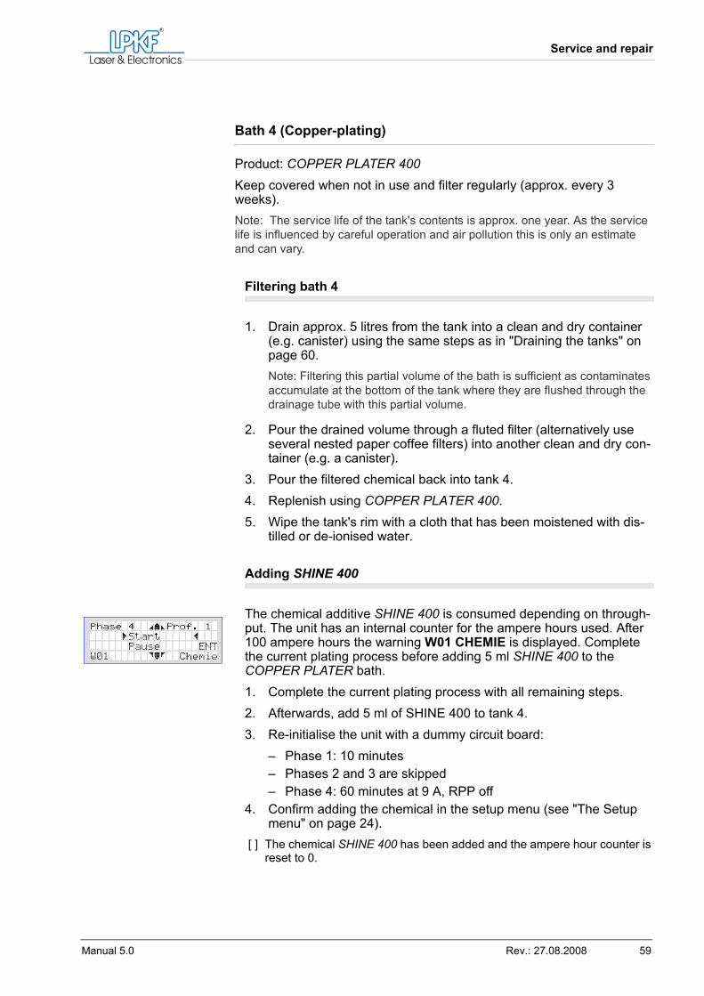
Adding SHINE 400
The chemical additive SHINE 400 is consumed depending on through-put. The unit has an internal counter for the ampere hours used. After 100 ampere hours the warning W01 CHEMIE is displayed. Complete the current plating process before adding 5 ml SHINE 400 to the COPPER PLATER bath.1. Complete the current plating process with all remaining steps.2. Afterwards, add 5 ml of SHINE 400 to tank 4.3. Re-initialise the unit with a dummy circuit board:
– Phase 1: 10 minutes– Phases 2 and 3 are skipped– Phase 4: 60 minutes at 9 A, RPP off
4. Confirm adding the chemical in the setup menu (see "The Setup menu" on page 24).
[ ] The chemical SHINE 400 has been added and the ampere hour counter is reset to 0.
Service and repair by user
60 MiniContac RS
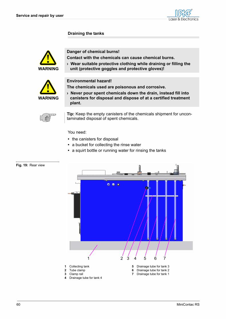
Draining the tanks
You need:• the canisters for disposal• a bucket for collecting the rinse water• a squirt bottle or running water for rinsing the tanks
WARNING
Danger of chemical burns!Contact with the chemicals can cause chemical burns.› Wear suitable protective clothing while draining or filling the
unit (protective goggles and protective gloves)!
WARNING
Environmental hazard!The chemicals used are poisonous and corrosive.› Never pour spent chemicals down the drain, instead fill into
canisters for disposal and dispose of at a certified treatment plant.
Tip: Keep the empty canisters of the chemicals shipment for uncon-taminated disposal of spent chemicals.
Fig. 19: Rear view
1 Collecting tank2 Tube clamp3 Clamp rail4 Drainage tube for tank 4
5 Drainage tube for tank 36 Drainage tube for tank 27 Drainage tube for tank 1
1 2 4 5 6 73
Service and repair
Manual 5.0 Rev.: 27.08.2008 61
For draining each of the tanks (1 to 4) proceed as follows:1. Pull the drainage tube from the clamp rail.2. Clamp the tube shut above the fluid level with the tube clamp sup-
plied with the unit.3. While still holding the tube upwards pull off the stopper.4. Insert the tube's end into the corresponding canister.5. Open the clamp enabling the chemical to drain from the tank.6. When the tank is drained completely put the tube's end into the
bucket for the rinse water.7. Tank 4: Rinse the anodes and the tank:
– Unscrew the anode bolts (see fig. 10, "Copper anodes", on page 33).
– Remove the anodes with the anode cloth bags.– Rinse and scrub the anodes clean with a plastic brush or replace
them if they are overly worn.– Rinse or replace the anode cloth bags.– Rinse the tank thoroughly.– Reinsert the anodes with the anode cloth bags and fasten them
with the anode bolts (see "Mounting the copper anodes" on page 33).
8. Tanks 1/2/3: Rinse the tank thoroughly.9. Tank 3: Rinse the tank again with distilled or de-ionised water.10. Let the rinse water drain completely into the bucket and dispose of
via the sewer system.11. Seal the tube with the stopper and re-insert it back into the clamp
rail.12. Dry the tank.[ ] The tank is drained and can be refilled.

Service and repair by user
62 MiniContac RS
Storage
Manual 5.0 Rev.: 27.08.2008 63
9. Storage
9.1 Decommissioning
Decommissioning the unit
1. Unplug the mains cable.2. Wait until bath 1 has cooled down.3. Drain the chemicals into their respective canisters.4. Rinse the tanks of the unit thoroughly.5. Rinse tank 3 with distilled or de-ionised water.6. Unscrew the anode bolts (see fig. 10, "Copper anodes", on
page 33).7. Remove the anodes with the anode cloth bags.8. Re-install the anode bolts.9. Rinse the anode bags and rinse and scrub the anodes clean with a
plastic brush.10. Dry the anodes and anode cloth bags.
Note: Depending on wear replace the anodes and anode bags before putting the unit back into service.
11. Dry the tanks.[ ] The unit is decommissioned and can now be packed.
Packing the unit
1. Remove and pack the loose components (tank covers, digital ther-mometer etc.) of the unit.
2. Retrieve the original packaging from storage or procure safe pack-aging.
3. Pack the unit.4. Ensure safe transport in horizontal position by applying appropriate
marks on the package (e.g. "fragile", "UP").[ ] The unit is packed and can be transported or stored.
WARNING
Lifting hazard — heavy object.The unit weighs approx. 47 kg. Single person lifting could cause muscle strain or back injury.› Always have two persons of adequate physical strength lift,
move, or install the unit.
Storage
64 MiniContac RS
9.2 Storage
Store the unit in a frost-free and dry place.
9.3 Disposal
Disposing of the unit
1. Decommission the unit (see chapter 9.1‚ "Decommissioning").2. Dispose of the chemicals separately as described in chapter 6.5‚
"Waste Disposal", on page 52.3. Dispose of the unit in adherence to local regulations concerning
plastics and electronic components.[ ] The unit is disposed of.
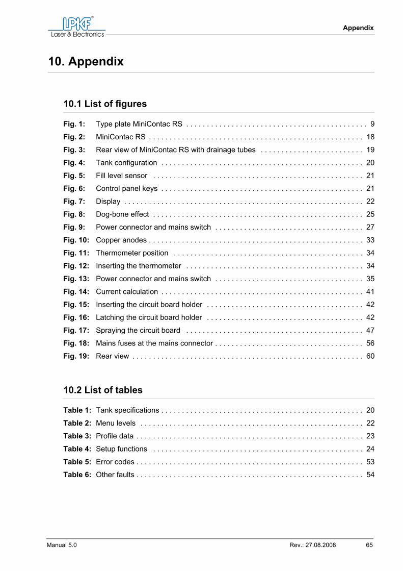
Appendix
Manual 5.0 Rev.: 27.08.2008 65
10. Appendix
10.1 List of figures
Fig. 1: Type plate MiniContac RS . . . . . . . . . . . . . . . . . . . . . . . . . . . . . . . . . . . . . . . . . . . . 9
Fig. 2: MiniContac RS . . . . . . . . . . . . . . . . . . . . . . . . . . . . . . . . . . . . . . . . . . . . . . . . . . . . 18
Fig. 3: Rear view of MiniContac RS with drainage tubes . . . . . . . . . . . . . . . . . . . . . . . . . 19
Fig. 4: Tank configuration . . . . . . . . . . . . . . . . . . . . . . . . . . . . . . . . . . . . . . . . . . . . . . . . . 20
Fig. 5: Fill level sensor . . . . . . . . . . . . . . . . . . . . . . . . . . . . . . . . . . . . . . . . . . . . . . . . . . . 21
Fig. 6: Control panel keys . . . . . . . . . . . . . . . . . . . . . . . . . . . . . . . . . . . . . . . . . . . . . . . . . 21
Fig. 7: Display . . . . . . . . . . . . . . . . . . . . . . . . . . . . . . . . . . . . . . . . . . . . . . . . . . . . . . . . . . 22
Fig. 8: Dog-bone effect . . . . . . . . . . . . . . . . . . . . . . . . . . . . . . . . . . . . . . . . . . . . . . . . . . . 25
Fig. 9: Power connector and mains switch . . . . . . . . . . . . . . . . . . . . . . . . . . . . . . . . . . . . 27
Fig. 10: Copper anodes . . . . . . . . . . . . . . . . . . . . . . . . . . . . . . . . . . . . . . . . . . . . . . . . . . . . 33
Fig. 11: Thermometer position . . . . . . . . . . . . . . . . . . . . . . . . . . . . . . . . . . . . . . . . . . . . . . 34
Fig. 12: Inserting the thermometer . . . . . . . . . . . . . . . . . . . . . . . . . . . . . . . . . . . . . . . . . . . 34
Fig. 13: Power connector and mains switch . . . . . . . . . . . . . . . . . . . . . . . . . . . . . . . . . . . . 35
Fig. 14: Current calculation . . . . . . . . . . . . . . . . . . . . . . . . . . . . . . . . . . . . . . . . . . . . . . . . . 41
Fig. 15: Inserting the circuit board holder . . . . . . . . . . . . . . . . . . . . . . . . . . . . . . . . . . . . . . 42
Fig. 16: Latching the circuit board holder . . . . . . . . . . . . . . . . . . . . . . . . . . . . . . . . . . . . . . 42
Fig. 17: Spraying the circuit board . . . . . . . . . . . . . . . . . . . . . . . . . . . . . . . . . . . . . . . . . . . 47
Fig. 18: Mains fuses at the mains connector . . . . . . . . . . . . . . . . . . . . . . . . . . . . . . . . . . . . 56
Fig. 19: Rear view . . . . . . . . . . . . . . . . . . . . . . . . . . . . . . . . . . . . . . . . . . . . . . . . . . . . . . . . 60
10.2 List of tables
Table 1: Tank specifications . . . . . . . . . . . . . . . . . . . . . . . . . . . . . . . . . . . . . . . . . . . . . . . . . 20
Table 2: Menu levels . . . . . . . . . . . . . . . . . . . . . . . . . . . . . . . . . . . . . . . . . . . . . . . . . . . . . . 22
Table 3: Profile data . . . . . . . . . . . . . . . . . . . . . . . . . . . . . . . . . . . . . . . . . . . . . . . . . . . . . . . 23
Table 4: Setup functions . . . . . . . . . . . . . . . . . . . . . . . . . . . . . . . . . . . . . . . . . . . . . . . . . . . 24
Table 5: Error codes . . . . . . . . . . . . . . . . . . . . . . . . . . . . . . . . . . . . . . . . . . . . . . . . . . . . . . . 53
Table 6: Other faults . . . . . . . . . . . . . . . . . . . . . . . . . . . . . . . . . . . . . . . . . . . . . . . . . . . . . . . 54
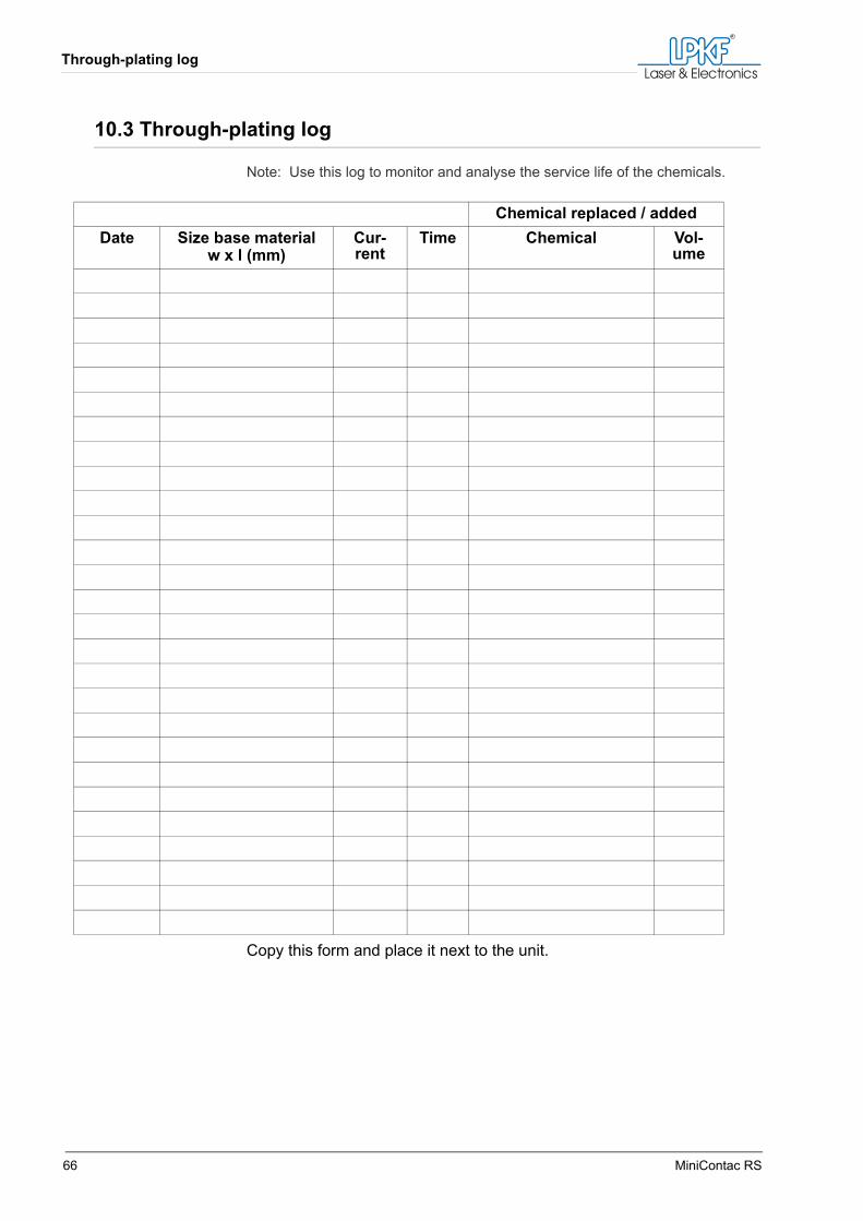
Through-plating log
66 MiniContac RS
10.3 Through-plating log
Note: Use this log to monitor and analyse the service life of the chemicals.
Copy this form and place it next to the unit.
Chemical replaced / addedDate Size base material
w x l (mm)Cur-rent
Time Chemical Vol-ume
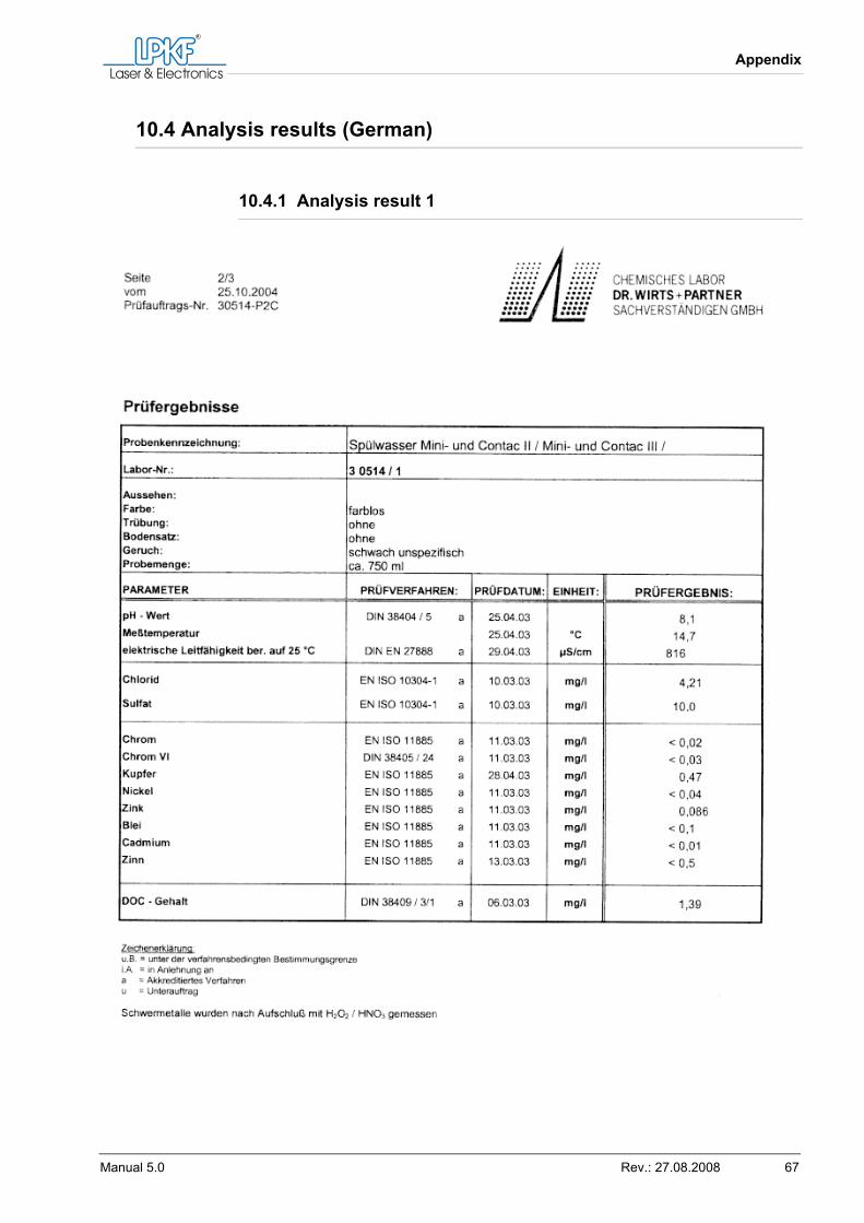
Appendix
Manual 5.0 Rev.: 27.08.2008 67
10.4 Analysis results (German)
10.4.1 Analysis result 1
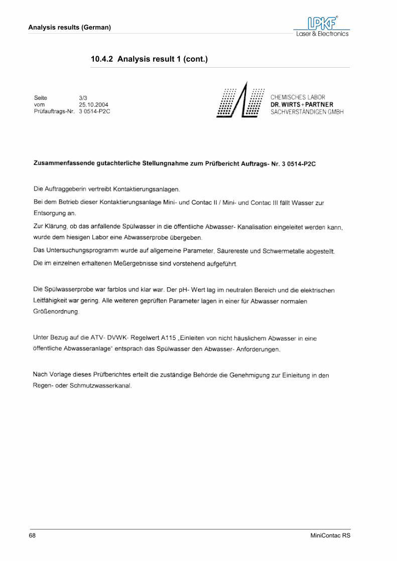
Analysis results (German)
68 MiniContac RS
10.4.2 Analysis result 1 (cont.)
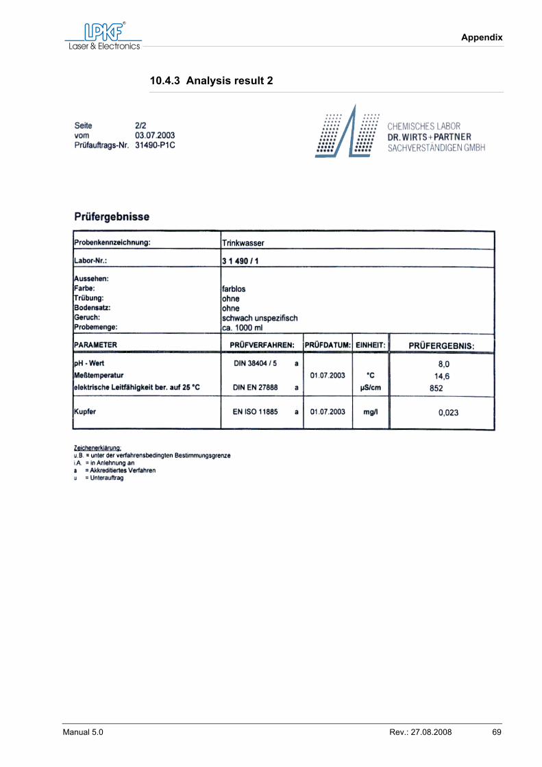
Appendix
Manual 5.0 Rev.: 27.08.2008 69
10.4.3 Analysis result 2
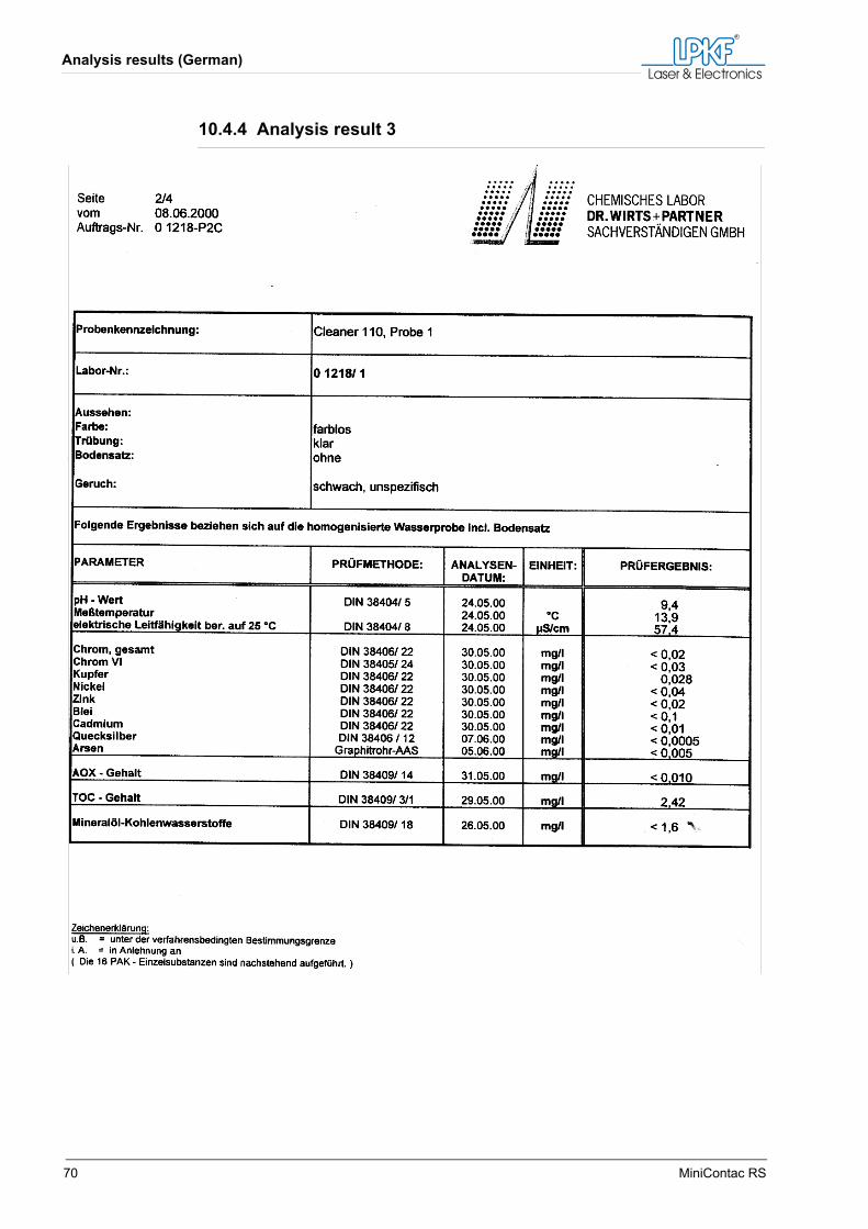
Analysis results (German)
70 MiniContac RS
10.4.4 Analysis result 3
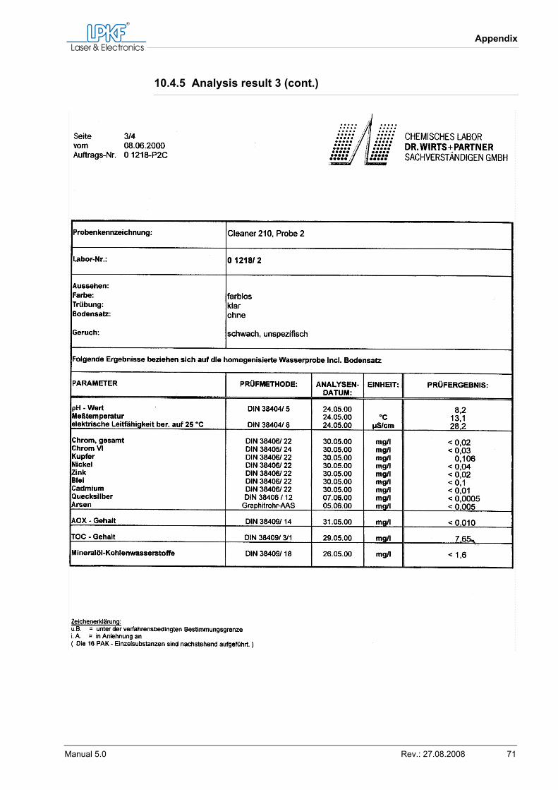
Appendix
Manual 5.0 Rev.: 27.08.2008 71
10.4.5 Analysis result 3 (cont.)

Analysis results (German)
72 MiniContac RS
10.4.6 Analysis result 3 (cont.)
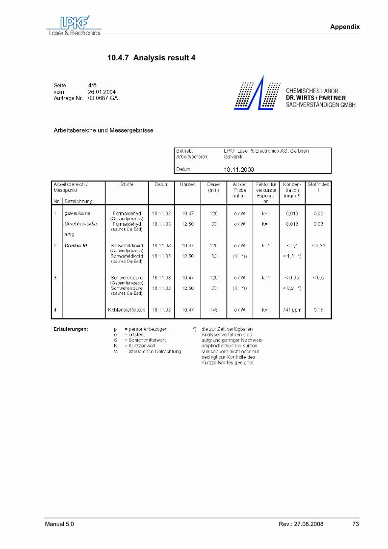
Appendix
Manual 5.0 Rev.: 27.08.2008 73
10.4.7 Analysis result 4
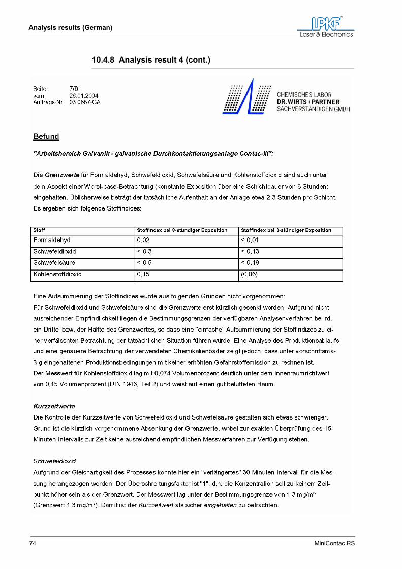
Analysis results (German)
74 MiniContac RS
10.4.8 Analysis result 4 (cont.)
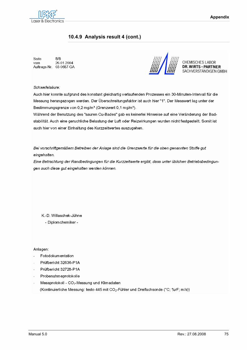
Appendix
Manual 5.0 Rev.: 27.08.2008 75
10.4.9 Analysis result 4 (cont.)
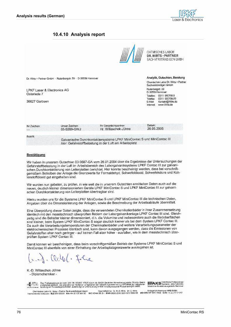
Analysis results (German)
76 MiniContac RS
10.4.10 Analysis report
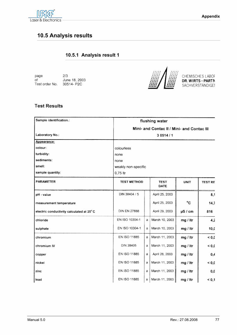
Appendix
Manual 5.0 Rev.: 27.08.2008 77
10.5 Analysis results
10.5.1 Analysis result 1
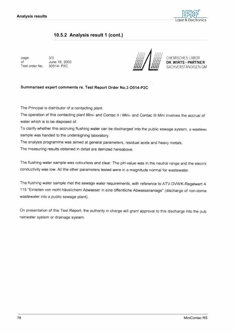
Analysis results
78 MiniContac RS
10.5.2 Analysis result 1 (cont.)
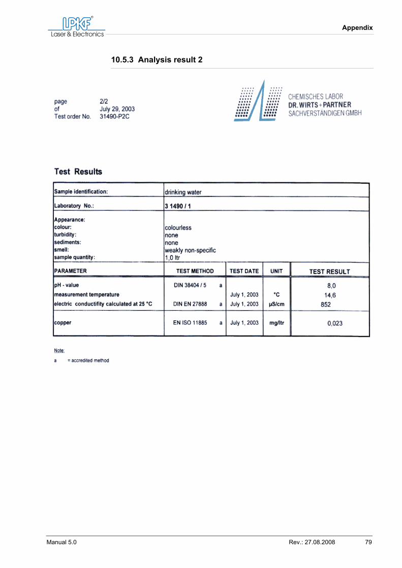
Appendix
Manual 5.0 Rev.: 27.08.2008 79
10.5.3 Analysis result 2
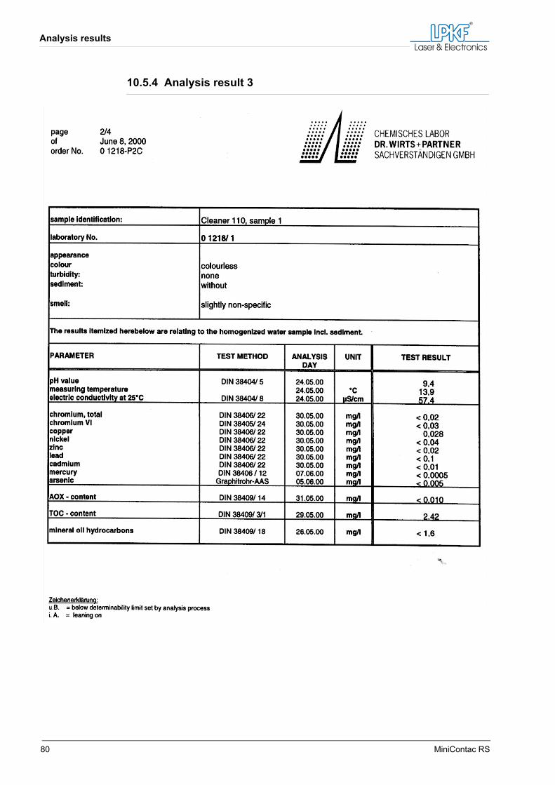
Analysis results
80 MiniContac RS
10.5.4 Analysis result 3
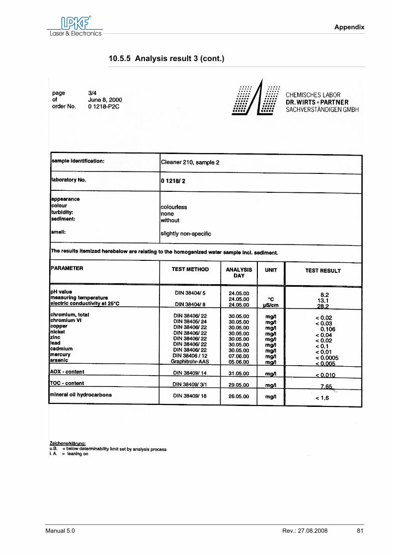
Appendix
Manual 5.0 Rev.: 27.08.2008 81
10.5.5 Analysis result 3 (cont.)
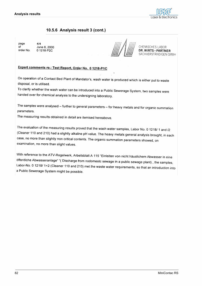
Analysis results
82 MiniContac RS
10.5.6 Analysis result 3 (cont.)
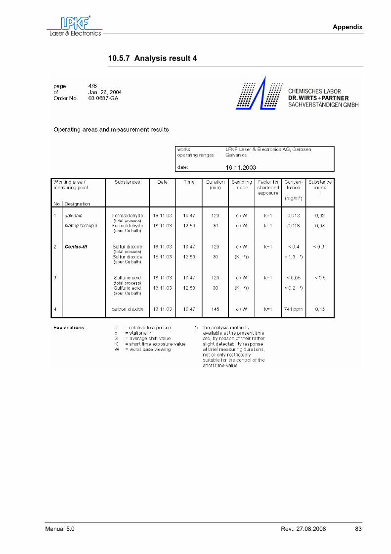
Appendix
Manual 5.0 Rev.: 27.08.2008 83
10.5.7 Analysis result 4
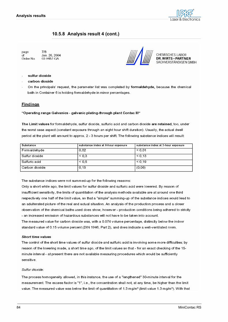
Analysis results
84 MiniContac RS
10.5.8 Analysis result 4 (cont.)
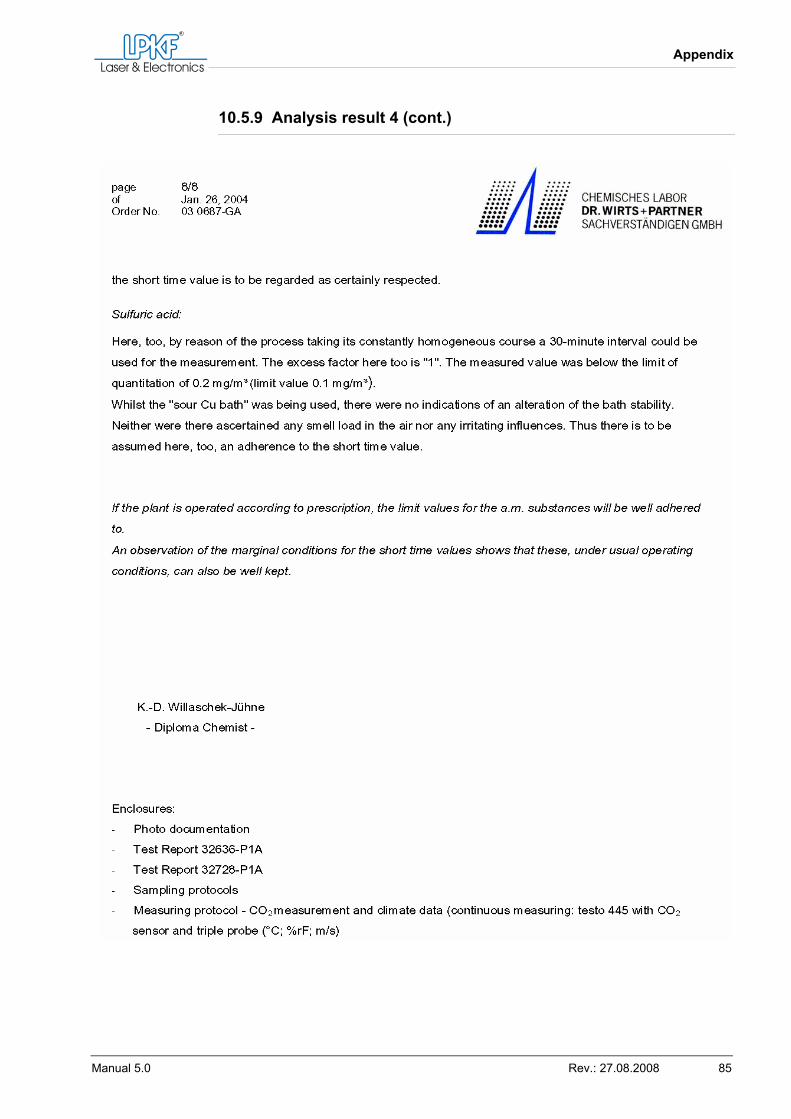
Appendix
Manual 5.0 Rev.: 27.08.2008 85
10.5.9 Analysis result 4 (cont.)
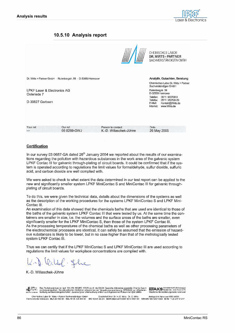
Analysis results
86 MiniContac RS
10.5.10 Analysis report
Appendix
Manual 5.0 Rev.: 27.08.2008 87
10.6 Glossary
Black Hole processIn this process, the circuit board is wetted with a graphite solution. The solution is dried. Subsequently, the graphite layer is removed from the copper. In the via holes where the surface is rough with glass fibres and epoxy the graphite remains and thus forms a conductive surface.RCDAn RCD (Residual Current Device) is an electrical device that discon-nects a circuit whenever it detects that the electric current is not balanced between the phase conductor and the neutral conductor. Such an imbal-ance can be caused by current leakage through the body of a person who is grounded and accidentally touching the energised part of the cir-cuit. RCDs are designed to disconnect quickly enough to mitigate the harm caused by electrical shock in such a case.

Glossary
88 MiniContac RS