Embed Size (px)
Citation preview
SMART INDUSTRIES CORP., MFG.
MANUAL
SMART INDUSTRIES CORP., MFG.
1626 Delaware Ave. • Des Moines, Iowa 50317 (515) 265-9900 • (800) 553-2442 • FAX: 515-265-3148

V
V
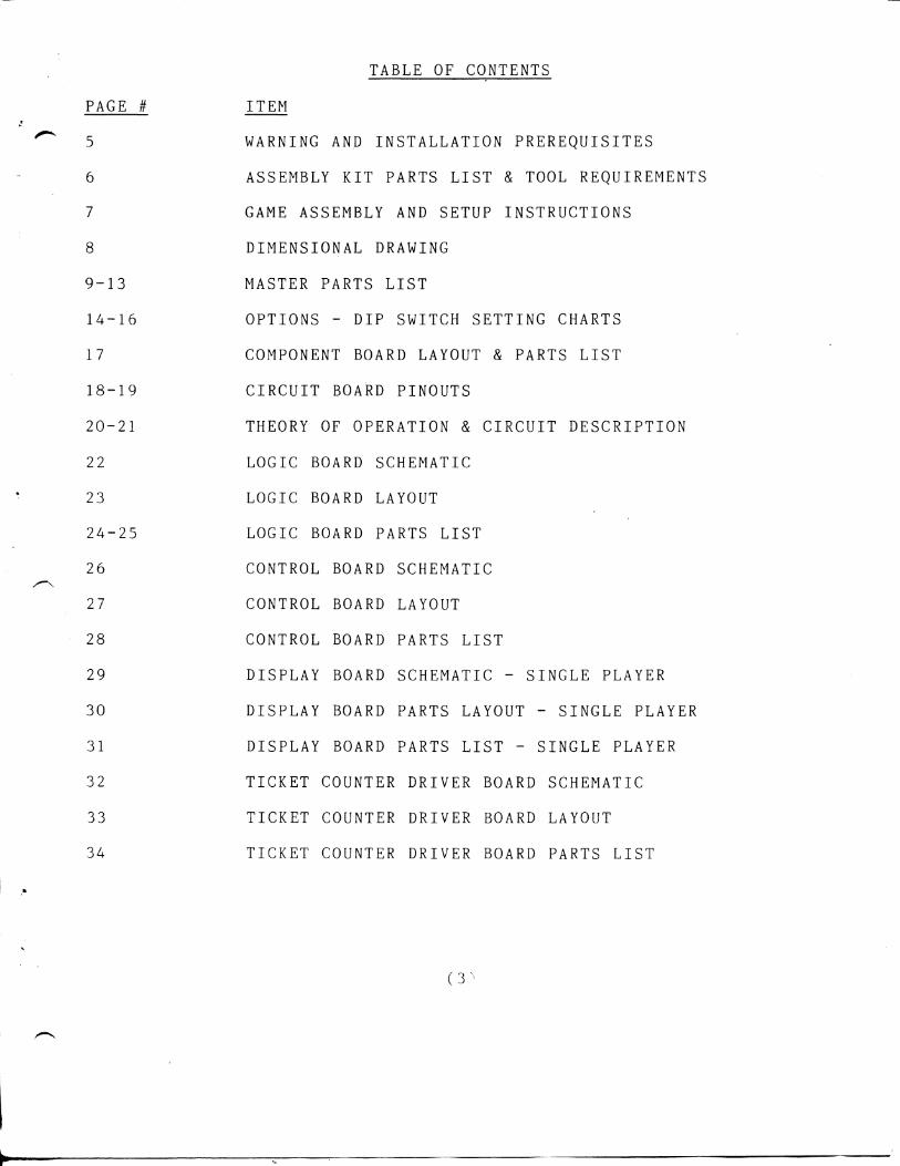
TABLE OF CONTENTS
PAGE # ITEM
5 WARNING AND INSTALLATION PREREQUISITES
6 ASSEMBLY KIT PARTS LIST & TOOL REQUIREMENTS
7 GAME ASSEMBLY AND SETUP INSTRUCTIONS
8 DIMENSIONAL DRAWING
9-13 MASTER PARTS LIST
14-16 OPTIONS - DIP SWITCH SETTING CHARTS
17 COMPONENT BOARD LAYOUT & PARTS LIST
18-19 CIRCUIT BOARD PINOUTS
20-21 THEORY OF OPERATION & CIRCUIT DESCRIPTION
22 LOGIC BOARD SCHEMATIC
23 LOGIC BOARD LAYOUT
24-25 LOGIC BOARD PARTS LIST
26 CONTROL BOARD SCHEMATIC
27 CONTROL BOARD LAYOUT
28 CONTROL BOARD PARTS LIST
29 DISPLAY BOARD SCHEMATIC - SINGLE PLAYER
30 DISPLAY BOARD PARTS LAYOUT - SINGLE PLAYER
31 DISPLAY BOARD PARTS LIST - SINGLE PLAYER
32 TICKET COUNTER DRIVER BOARD SCHEMATIC
33 TICKET COUNTER DRIVER BOARD LAYOUT
34 TICKET COUNTER DRIVER BOARD PARTS LIST
(3

35 CREDIT COUNTER DRIVE BOARD SCHEMATIC & PARTS LAYOUT
36 CREDIT COUNTER DRIVE BOARD PARTS LIST
37 BALL RELEASE ASSEMBLY DETAIL DRAWING &
PARTS LIST
38 TM-4 TICKET DISPENSER SCHEMATIC DIAGRAM
39 TM-4 TICKET DISPENSER LOADING INSTRUCTIONS

WARNING SHOCK HAZARD
Connect t h i s game o n l y t o a grounded 3 w i r e o u t l e t . I f you have o n l y a 2 w i r e o u t l e t , we recommend you h i r e a l i c e n s e d e l e c t r i c i a n t o i n s t a l l a grounded o u t l e t f o r s a f e t y purposes.
P l a y e r s c o u l d r e c e i v e an e l e c t r i c shock i f t h i s game i s n o t p r o p e r l y grounded!!!
GAME INSPECTION
Your c a r e f u l i n s p e c t i o n i s needed t o s u p p l y t h e f i n a l t o u c h o f q u a l i t y c o n t r o l . Please f o l l o w t h e s e i n s t r u c t i o n s t o h e l p us i n s u r e t h a t y o u r new game was d e l i v e r e d t o you i n good c o n d i t i o n .
DO NOT PLUG I N AT THIS TIME.
1. Examine t h e e x t e r i o r o f t h e s c o r i n g c a b i n e t and p l a y f i e l d f o r d e n t s , c h i p s o r broken p a r t s .
2. Remove t h e Marque P l a s t i c f r o m t h e f r o n t o f t h e s c o r i n g c a b i n e t . P l a c e t h e Marque i n a s a f e l o c a t i o n as i t w i l l n o t be r e - i n s t a l l e d u n t i l assembly i s co m p l e t e . I n s p e c t t h e i n t e r i o r o f t h e s c o r i n g c a b i n e t f o r damage and/or l o o s e p a r t s . P e r f o r m v i s u a l i n s p e c t i o n f o r l o o s e w i r e s and check a l l p l u g - i n c o n n e c t o r s t o assure t h e y a r e f i r m l y s e a t e d . Check s c r e w - i n l i g h t b u l b s f o r s e a t i n g i n s o c k e t s .
POWER REQUIREMENTS:
DOMESTIC - 120 V 60 HZ. FOREIGN - 200 t o 240 V 50 HZ CONSUMPTION - Not t o exceed .350 KVA MAIN FUSE - 5 AMP. STEP DOWN TRANSFORMER (FOREIGN) - .500 KVA w i t h 3 AMP. SLO-
BLOW FUSE.
(5)

ASSEMBLY KIT PARTS LIST AND TOOL REQUIREMENTS
The f o l l o w i n g i t e m s a r e i n c l u d e d i n t h e b o l t bag r e c e i v e d w i t h y o u r SMART BALL GAME:
2 1/2-13 X 3" Hex Head Machine B o l t s 2 1/2" S p l i t Lock Washers 2 1/2-13 Hex Nuts 4 5/16-18 X 2 1/2" C a r r i a g e B o l t s 4 5/16" S p l i t Lock Washers 4 5/16-18 Hex Nuts 6 #8 X 3/4" P a r t i c l e Board Screws
Recommended t o o l s f o r t h e assembly o f y o u r SMART BALL GAME a r e :
1 1/2" D r i v e R a t c h e t Wrench w i t h 1/2" and 3/4" s o c k e t s 1 3/4" Box End Wrench 1 #2 P h i l l i p s Screw D r i v e r
A l s o recommended a r e (4) 4" x 4" Padded wooden b l o c k s t o l a y t h e game on d u r i n g assembly.
(6)

ASSEMBLY INSTRUCTIONS
1. R e p o s i t i o n t h e b a l l c o u n t i n i c r o s w i t c h m o u n t i n g b r a c k e t . T h i s i s acco m p l i s h e d by removing t h e two 1/4-20 x 1" machine b o l t s f r o m t h e mounting b r a c k e t and w i t h o u t r e moving t h e w i r e harness from t h e m i c r o s w i t c h , r o t a t e t h e m i c r o s w i t c h b r a c k e t assembly 180 degrees and b o l t i t back t o t h e c a b i n e t f a c e p l a t e . When completed t h e b a l l c o u n t i n g b r a c k e t s h o u l d p r o t r u d e o u t t h r o u g h t h e b a l l r e t u r n o u t l e t .
2. Lay b o t h t h e c o n t r o l c o n s o l e c a b i n e t and t h e a l l e y on t h e i r s i d e s . NOTE: To p r e v e n t m a r r i n g o f t h e p a i n t e d s i d e s o f t h e game, l a y t h e game on c a r p e t p i e c e s o r c l e a n c a r d b o a r d . J o i n t h e c o n t r o l c o n s o l e c a b i n e t t o t h e a l l e y u s i n g two 1/2-13 X 3" machine b o l t s s u p p l i e d .
3. Two harnesses a r e used i n t h e Smart B a l l game. The s i g n a l h a r n e s s i s r o u t e d on t h e l e f t s i d e o f t h e a l l e y w h i l e t h e "AC" ha r n e s s i s r o u t e d on t h e r i g h t s i d e o f t h e a l l e y . The c o n t r o l c o n s o l e p o r t i o n and t h e a l l e y p o r t i o n o f t h e s e h a r n esses a r e j o i n e d w i t h c o n n e c t o r s a p p r o x i m a t e l y 18 i n c h e s f r o m t h e a l l e y f a c e p l a t e . For s h i p p i n g p u r p o s e s , t h e con t r o l c o n s o l e harnesses a r e r e s t r a i n e d i n t h e l o w e r p o r t i o n o f t h e c o n s o l e w i t h w i r e t i e s . Remove t h e s h i p p i n g w i r e t i e s and d r e s s b o t h harnesses t h r o u g h t h e h o l e s p r o v i d e d i n t h e c o n t r o l c o n s o l e and a l l e y f a c e p l a t e s . J o i n t h e c o n n e c t o r s on b o t h harnesses.
4. I n s e r t t h e two, 1 1/4" square s t e e l , l e g s i n t o t h e h o l e s p r o v i d e d t h r o u g h t h e f l o o r a t t h e r e a r o f t h e c o n t r o l c o n s o l e . A l i g n t h e b o l t h o l e s w i t h t h e h o l e s t h r o u g h t h e s i d e s o f t h e c o n t r o l c o n s o l e and f a s t e n w i t h 5/16-18 x 2 1/2 c a r -r a i g e b o l t s . I n s t a l l t h e b o l t s f r o m t h e o u t s i d e , p o s i t i o n i n g t h e n u t s on t h e i n s i d e o f t h e c a b i n e t . For access t o i n s t a l l t h e l e g on t h e lower s i d e , p l a c e 4" b l o c k s under t h e assemb l y . T i g h t e n t h e n u t s VERY s e c u r e l y .
5. Set t h e game u p r i g h t . FOR SAFETY I T I S RECOMMENDED TWO MEN BE UTILIZED TO SET THE GAME UP.
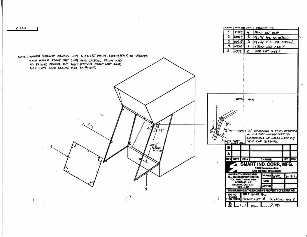
6. I n s t a l l t h e s i d e n e t frames. Use t h r e e #8 x 3/4" p a r t i c l e b o a r d screws t o a t t a c h t h e frame t o t h e c o n t r o l c o n s o l e . FRONT NET: The f r o n t n e t i s an a v a i l a b l e o p t i o n . Supplimen-t a l assembly i n s t r u c t i o n s a r e s u p p l i e d w i t h t h i s o p t i o n .
7. T h i s c o m p letes assembly. The POWER SWITCH i s l o c a t e d i n t h e l e f t f r o n t c o r n e r o f t h e upper p o r t i o n o f t h e c o n t r o l c o ns o l e . P l u g t h e game i n t o t h e power l i n e s o u r c e and t u r n t h e power s w i t c h on. R e - i n s t a l l t h e Marque P l a s t i c .
(7)


MASTER PARTS LIST
PART NUMBER DESCRIPTION QUANTITY
0133 M i c r o s w i t c h b o l t spacer 2 ^ 0348 Door l a t c h t i c k e t d i s p e n s e r & r e a r door 2
11172 Screw #6 X 1/2" PPH wood 8 11178 Screw #4-40 X 3/4 PPH MS 8 1768 B r a c k e t , f u s e & t o g g l e s w i t c h 2 2096 B r a c k e t , s c o r e r i n g s m a l l 28 (36) 2097 Large s c o r e r i n g b r a c k e t 6 2098 Score r i n g c o n n e c t i n g b r a c k e t 4 (6) 2099 DBA cov e r p l a t e 1 2100 Speaker g r i l l 1 2102 I n n e r cover - b a l l r e t u r n 2 2104 Hinge p l a t e - r e a r door 2 2105 T-brace assembly 1 (3) 2106 Leg 2 2107-02 Marque, r e t a i n e r r e d 1 2108 A l l e y s t r a p 1 2111 C o in s l i d e assembly 1 2113 Coin mech s l i d e 1 2114 S l i d e h o u s i n g assembly 1 2115 Net frame assembly, l e f t 1 2116 Net frame assembly, r i g h t 1 2124 Coin box assembly 1 2133 L i g h t h o l d e r 2 2143 A l l e y edge, s t a i n l e s s s t e e l 1 2144 P l a y f i e l d l i g h t b r a c k e t 2 2155 DBA & c o i n mech h o u s i n g assembly 1
^ 2156 Co n n e c t i n g r o d 1 ^ 2157 S o l e n o i d b r a c k e t 1
2158 A d j u s t m e n t p i v o t 1 2162 R a i l - 13 f o o t 1 2165 B a l l r e l e a s e 1 2166 A l l e y f o o t 2 2170 A l l e y r a i l g u i d e 2 2173 A l l e y t r i m - 13 f o o t 2 2176 A l l e y t r i m - f r o n t 2 2188 Back door 1 2190 B a l l r e t u r n board 1 2200 Thermoform h o l d e r 2 2203 S c o r i n g board w/bonus assembly 0 (1) 2204 S c o r i n g board assembly 1 (0) 2207 Face p l a t e c o r k 1 2210 S c o r i n g c a b i n e t back c o r k 1 2221 B a l l r e l e a s e p i v o t assembly 1 2254 Co n n e c t i n g arm assembly 1 2264 Coinbox i n s e r t 1 2265 Cover p l a t e 1 2270 B a l l r e l e a s e s t o p assembly 1 2274 B a l l r e l e a s e l o c k assembly 1 2278 Door, DBA 1 2279 Door, c o i n mechanism 1 2282 D i s p l a y s t o p 2 2290 Bonus b a l l r e t u r n , r i g h t 0 (1)
^ 2291 Bonus b a l l r e t u r n , l e f t 0 (1) 2292-01 Lh bonus m i c r o s w i t c h h o l d e r 0 (1) 2292-02 Rh bonus m i c r o s w i t c h h o l d e r 0 (1)
(9)

MASTER PARTS LIST
PART NUMBER DESCRIPTION QUANTITY
2296 M i c r o s w i t c h form 2 2 3 00 Trough bumper 1 ^ 2306 S o l e n o i d cover 1 23 08 Assembly, t i c k e t d i s p e n s e r c over 1 2 315 F r o n t r h a l l e y s i d e cover 1 2317 A l l e y 1/r s i d e c o v e r - f r o n t 1 2318 Rear r h a l l e y s i d e cover 1 2321 Rear l h a l l e y s i d e cover 1 23 37 F r o n t n e t , c l i p 4 2 338 F r o n t n e t , l e x a n 1 23 39 Assembly, f r o n t n e t frame 1 2451 PCB assembly C o n t r o l 1 2452 PCB assembly. One Pl a y e r D i s p l a y 1 2461 PCB assembly. T i c k e t Counter 1 2463 PCB assembly. C r e d i t Counter 1 2471-03 PCB assembly, 2nd Gen 8031 Game Board 1 2496 Support, l i g h t b r a c k e t 1 2508 Net, t o p cosmetic f r o n t 1 2510 Top n e t assembly 1 2 513 L a t c h , DBA & c o i n door 2 2514 P r o t e c t o r , l i g h t 2 2521 Vent g r i l l 2 2525 Speaker g r i l l 1 252 6 R e t a i n e r , marque s w i v e l 2 2532 Sand bag assembly,small (50) 1 2 53 3 Sand bag assembly medium 1 2534 Sand bag assembly l a r g e 1 ^ 2535-2 B a l l r a i l assembly 1 2556 Bumper, b l a c k PVC, 1" X 1/2" X 9" 2 2557 Cover, w i r e 24" 1 2558 Cover, w i r e 4" 1 2559 Trough, s c o r i n g 1 (0) 2559-01 Trough, bonus s c o r i n g assembly 0 (1) 2560 Trough, bottom, b l a c k abs p i 1 2561 "Hazard" l a b e l 1 2562 Decal, s i d e 2 2563 Decal, f a c e p l a t e • 1 2564 Decal, p r e s s s t a r t t o b e g i n 1 2574 Dispenser, t i c k e t #2 p l a s t i c 1 2575 Net, "U" channel s i d e 2 2579 Harness, a l l e y b a l l r e l e a s e , 10 f o o t 1 2580 Harness, a l l e y b a l l r e l e a s e , 13 f o o t 1 2581 Harness, a l l e y s i g n a l , 10 f o o t 1 2582 Harness, a l l e y s i g n a l , 13 f o o t 1 2583 Harness, c a b i n e t b a l l r e l e a s e 1 2584 Harness, c a b i n e t s i g n a l 1 2585 Harness, c a b i n e t AC w i r i n g 1 2586 Harness, t i c k e t d i s p e n s e r , 2000 s e r i e s 1 2587 Harness, c o i n mechanism 1 2 588 Harness, component board 1 2590 Harness, s i n g l e p l a y e r d i s p l a y 1 2591 Harness, f o u r p l a y e r d i s p l a y 1 ^ 2592 Cover, c o i n box 1 2 62 6 Bumper, hose 1 2627 Bumper, wood dowel 1
( 1 0 )

MASTER PARTS LIST
PART NUMBER DESCRIPTION QUANTITY
2648 Marque "T" m o l d i n g 3/4" 2 2649 Marque "T" m o l d i n g 13/16" 1 2656 D i s p l a y , r e d l e n s s i n g l e 1 2666 D e c a l , "TICKET" 1 2729 Harness, t i c k e t d i s p e n s e r , 4000 s e r i e s 1 2751 C a b i n e t f i n a l assembly 1 2752 A l l e y assembly f i n a l 13 f o o t 1 2756-01 Non bonus t a r g e t b oard assembly 1 (0) 2756-02 Bonus t a r g e t b oard assembly 0 (1) 2757 Component board assembly 1 2762 S c o r i n g t r o u g h assembly, non bonus 1 2763 Bottom t r o u g h assembly 1 2764 Bumper, T-brace 1 2766 50 P t . s c o r i n g r i n g 1 2767 40 P t . s c o r i n g r i n g 1 2768 30 P t . s c o r i n g r i n g 1 2769 20 P t . s c o r i n g r i n g 1 2770 100 P t . s c o r i n g r i n g 0 (2) 2771 10 P t . s c o r i n g r i n g 1 2773-01 T i c k e t d i s p . f i n a l assembly 2000 1 2773-02 T i c k e t d i s p . f i n a l assembly 4000 1 2774 F r o n t n e t f i n a l assembly 1 2775-01 Side n e t f i n a l assembly 1 2775-02 Side n e t f i n a l assembly 1 2779-01 Marque assembly, s i n g l e p l a y e r 1 2779-02 Marque assembly, f o u r p l a y e r 1 2782-01 Lh bonus m i c r o s w i t c h assembly 0 (1) 2782-02 Rh bonus m i c r o s w i t c h assembly 0 (1) 2783 S c o r i n g t r o u g h assembly w i t h bonus 0 (1) 2784 l e g assembly 2 2865 Cover, f u s e & s w i t c h 1 2866 Cover, c o n t r o l b oard 1 2867 Cover, EMI f i l t e r 1 2872 PCB, Four P l a y e r "A" D i s p l a y 1 2886 PCB, Four P l a y e r "B" D i s p l a y 1 2947 B a l l c o u n t sensor b r a c k e t 1 2961 D i s p l a y back subassembly 1 3043 B a l l c o u n t sensor b r a c k e t assembly 1 3047 D i s p l a y assembly, s i n g l e p l a y e r 1 3048 D i s p l a y assembly, f o u r p l a y e r 1 3056 Harness, A-B d i s p l a y i n t e r c o n n e c t 1 50006 T e r m i n a l b l o c k 6 50011 Toggle S w i t c h , l l O V SPST 1 50012 Fu s e h o l d e r , p a n e l mount 2 50064 T r a n s f o r m e r , 115V/14V 6 Ampere 1 50065 F i l t e r , EMI, 120V/250V 5 Ampere 1 50066 T r a n s o r b 1.5KE220C 1 50067 Power c o r d , 10 f o o t , 18/3SJT 1 50252 Fuse, 5 Ampere AGC5 1 50287 C l u s t e r s o c k e t , #22259 1 50289 Nut, hex, 9/16"-18 I P , s t e e l 1 50294 Speaker, 8 Qhm,3 0 Watt 6" X 9" 1 50295 S o l e n o i d , b a l l r e l e a s e 1 50296 Push b u t t o n s w i t c h , s t a r t 1 50297 S w i t c h , s c o r i n g 5 (7)
] 1

MASTER PARTS LIST
PART NUMBER DESCRIPTION QUANTITY
50298 R e v o l v i n g l i g h t , w i n n e r 1 50299 Lamp, l i g h t p i l o t h o l d e r 1 50300 Lens, RED f o r #50299 1 50301 S w i t c h a c t u a t o r , 2" w i r e 5 (7) 50302 Fan 1 50303 B u l b , f l o o d , 50R20 SylVania 2 50304 Socket, p o r c e l a i n lamp 2 50305 B u l b , #912 m i n i a t u r e 4 (2) 50306 B u l b , #1895 m i n i a t u r e 3 (2) 50308 Socket, m i n i a t u r e bayonet 3 (2) 50320 1/2 Ampere slow blow f u s e 1 50479 Lamp h o l d e r , wedge base 4 (2) 60000 C o t t e r p i n , 1/16" X 3/4" 4 60001 C o t t e r p i n , 1/8" X 1" s t e e l 1 60003 Washer, l o c k , 5/16" 4 60004 Washer, f l a t , 5/16" 1 60005 Nut, hex, 5/16"-18 4 60007 Screw, PPH, #8-18 X 1/2" 7 60010 Screw, f l a t head, #8 X 1" 4 60016 Screw, PPH, #8 X 1/2" 49 60017 Screw, PPH, # 6 X 1 1/4" 24 60018 Nut, hex l/4"-20 1 60019 Washer, l o c k , 1/4" s p l i t 1 60021 Screw, PFH, #6 X 5/8" 12 60022 Screw, PPH, #8-18 X 3/4" 12 60046 Washer, l o c k , #10 s p l i t 19 60050 Screw, machine PPH, #4-40 X 3/4" 8 60057 Wire t i e , 4" n y l o n 29 60058 Lock, 7/8" t u b u l a r w i t h s t r cam 2 60062 S t a n d o f f , 1/2" X 1/2" n y l o n 35 60071 Washer, f l a t , 1/4" 1 60073 Nut, l o c k , #8-32 n y l o n i n s e r t 8 60074 Wire t i e , 7 1/2" n y l o n 112 60082 Washer, f l a t , 3/8" 9 60091 S t a n d o f f , 3/8" QD X 1/8" ID X 1/4" 20 60106 Nut, hex, #10-24 1 60109 Nut, #4-40 n y l o c k 25 60111 Washer, f l a t #4 22 60115 Washer, f l a t #8 18 60139 Lock, 1 1/8" c y l i n d e r w i t h cam 1 60155 Screw, PPH, #8 X 2" 4 60156 Screw, machine, PPH #8-32 X 1/4" 2 60157 Screw, PPH, #6 X 3/4" 78 60158 Screw, machine, PPH, #8-32 X 1/2" 8 60165 Nut, hex, #8-32 4 60168 Nut, hex, #10-32 12 60170 Lock, 7/8" c y l i n d e r w i t h cam 1 60198 Screw, machine, PPH, #8-32 X 1/2" 4 60202 Screw, PPH, #6 X 1/2" 19 60213 Screw, PPH, #8 X 3/4" 51 60219 B o l t , hex head, l/2"-13 X 3" 2 60220 Nut, l/2"-13 hex 2 60221 Washer, l o c k , 1/2" s p l i t 2 60225 Screw, machine, SHH, #4-40 X 1" 26 60234 L e v e l e r 3/8"-16 X 3" #FB3348 2
( 1 2 )

MASTER PARTS LIST
PART NUMBER DESCRIPTION QUANTITY
60239 Washer, l o c k , #8 s p l i t 2 60241 Coin mech c h a n n e l , c o i n 1 60243 Bushing, f l a n g e d o i l i t e , 1/4" 1 60245 Cam, l o c k , #7-602 h o o k i n g 2 60265 B o l t , hex head, l/4"-20 X 1 1/4" 1 60273 N u t s e r t s , P/N #4-40 AT52-440 20 60290 B o l t , l/4"-20 X 1" 2 60297 Grounding c l i p #8182-84-00 1 60300 B u l b , 69 Watt s t o p l i g h t 2 60301 N i p p l e , p i p e , NPT 1/2" X 1/2" 1 60303 De c a l , I n s e r t 2 5 Cents 1 60304 T i c k e t d i s p e n s e r , narrow f a c e 1 60308 Sup p o r t , c i r c u i t b o ard LCBS 6 60318 B o l t , hex head, 3/8"-16 X 1" 4 60320 Screw, p h i l pan head 1/4" M/S 2 60321 Screw, machine, PPH, #10-32 X 3/8" 8 60322 S o l e n o i d r e t u r n s p r i n g 1 60324 Coin mechanism 1 60325 Studs, c l i n c h #10-32 X 3/8" 10 60326 Cup, c o i n r e t u r n 1 60327 Coin meter 12 VDC 2 60328 Coin s l o t , t o p e n t r y , p l u n g e 1 60330 Turn b u c k l e #10-24 1 60331 B o l t , eye #10-24 X 3 1/2" 1 60332 Speednut f o r a c t u a t i n g w i r e 7 60333 R i v e t , s t e e l s p l i t 8
^ 60335 Number, 2" B l a c k v i n y l #0 16 60336 Number, 2" B l a c k v i n y l #1 5 60337 Number, 2" Bl a c k v i n y l #2 2 60338 Number, 2" Bl a c k v i n y l #3 2 60339 Number, 2" Bl a c k v i n y l #4 2 60340 Number, 2" Bl a c k v i n y l #5 2 60341 Washer, f i n i s h CTSK 41 60342 Screw, PPH, #8 X 1" 29 60343 Nut, l o c k , 1/2" t i g e r g r i p 2 60344 Screw, p h i l pan head #12 X 1/2" 8 60345 Bumper, t a c k y B l a c k #E6512 BL 2 60346 T i c k e t s , 1 5/32" X 2" Orange 1 60348 Wooden b a l l s , 3" u n f i n i s h e d 10 60349 C l i p , g r a t e r , 4 s i d e d #565-4 2 60351 Adhesive w i r e t i e MT 3/4" X 3" 10 60352 B o l t , s t e p , 5/16"-18 X 2 1/2" 4 60379 Sup p o r t , c i r c u i t b o ard 14 60422 Tinnerman n u t #10-32 2 60438 Bushing b r a s s 3/8" ID 1/2" 00 4 70148 Manual, S m a r t b a l l 1 70231 Tape Y e l l o w 1"
NOTE: Q u a n t i t i e s shown i n p a r e n t h e s i s r e f l e c t t h o s e r e q u i r e d when t h e bonus o p t i o n i s purchased and/or d i f f e r e n c e s r e q u i r e d f o r Four P l a y e r Games as opposed t o S i n g l e P l a y e r Games-
( 1 3 )

DIP SWITCH SETTINGS
SWITCH 1
P o s i t i o n OPTION
Number o f p o i n t s between t i c k e t s 1 2 ( A f t e r f i r s t t i c k e t d i s p e n s e )
ON ON 30 OFF ON 40 ON OFF 50 OFF OFF 70
3 4 Number o f t i c k e t s p e r d i s p e n s e
ON ON 0 OFF ON 1 ON OFF 2 OFF OFF 3
5 Number o f b a l l s p e r game
ON 6 OFF 9
6 7 P r i c e p e r game
ON ON $0.25 OFF ON 0.50 ON OFF 0.75 OFF OFF 1.00
8 A t t r a c t Mode (song & l i g h t )
ON on OFF o f f
14

SWITCH 2
Winner Score - F i r s t t i c k e t d i s -
ON OFF ON OFF ON OFF ON OFF
ON ON OFF OFF ON ON OFF OFF
1 2 3 pense, w i n n e r l i g h t and song.
ON ON ON 50 p o i n t s OFF ON ON 100 ON OFF ON 150 OFF OFF ON 200 ON ON OFF 350 OFF ON OFF 500 ON OFF OFF 700 OFF OFF OFF 900
High Score - Free game - S i n g l e 4 5 6 H i g h Score Song -
ON ON ON ON OFF OFF OFF OFF
50 p o i n t s 100 150 200 350 500 700 900
P l a y e r
ON OFF
Game Song - o v e r i d e
song e n a b l e d song d i s a b l e d
RESERVED - MUST BE TURNED OFF!
*NOTE: P l a y e r s p o i n t s earned must exceed H i g h Score p o i n t s s e t by DIP S w i t c h e s f o r a p p r o p r i a t e a c t i o n s t o o c c u r .
15
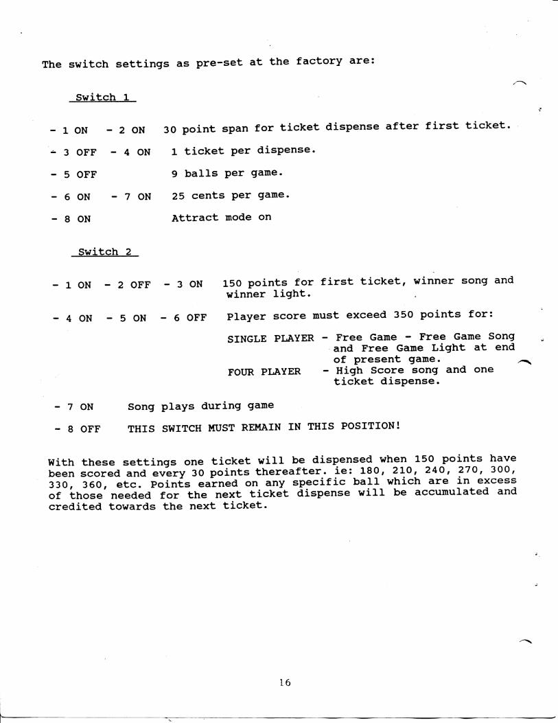
The s w i t c h s e t t i n g s as p r e - s e t a t t h e f a c t o r y a r e :
S w i t c h 1
1 ON - 2 ON 30 p o i n t span f o r t i c k e t d i s p e n s e a f t e r f i r s t t i c k e t ,
3 OFF - 4 ON 1 t i c k e t p e r d i s p e n s e .
5 OFF 9 b a l l s p e r game.
6 ON - 7 ON 25 c e n t s p e r game.
8 ON A t t r a c t mode on
S w i t c h 2
- 1 ON - 2 OFF - 3 ON 150 p o i n t s f o r f i r s t t i c k e t , w i n n e r song and win n e r l i g h t .
- 4 ON - 5 ON - 6 OFF P l a y e r s c o r e must exceed 350 p o i n t s f o r :
SINGLE PLAYER - Free Game - Free Game Song and Free Game L i g h t a t end o f p r e s e n t game.
FOUR PLAYER - Hi g h Score song and one t i c k e t d i s p e n s e .
- 7 ON Song p l a y s d u r i n g game
- 8 OFF THIS SWITCH MUST REMAIN I N THIS POSITION!
W i t h t h e s e s e t t i n g s one t i c k e t w i l l be d i s p e n s e d when 150 p o i n t s have been s c o r e d and e v e r y 30 p o i n t s t h e r e a f t e r , i e : 180, 210, 240, 270, 300, 330, 360, e t c . P o i n t s earned on any s p e c i f i c b a l l w h i c h a r e i n excess o f t h o s e needed f o r t h e n e x t t i c k e t d i s p e n s e w i l l be ac c u m u l a t e d and c r e d i t e d t o w a r d s t h e n e x t t i c k e t .
16

COMPONENT BOARD ASSEMBLY
1 0
I o o O I—."7"
5 ^
0 -
I t e m P a r t # Q u a n t i t y D e s c r i p t i o n 1 2191 1 PCB Mountinq Board 2 50195 1 Diode. KBL02 B r i d q e R e c t i f i e r 3 50339 1 C a o a c i t o r . 4700 uF @ 25 V 4 2866 1 Cover. C o n t r o l Board 5 2450 1 PCB Assembly. C o n t r o l Board 6 60017 8 Screw. # 6 x 1 1/4" PPH 7 60091 8 S t a n d o f f . 3/8" X 1/8" x 1/4" 8 60062 8 S t a n d o f f . 1/2" x 1/2" 9 2471-3 1 PCB Assembly. 8031 Board
10 50011 1 S w i t c h , T oaale. SPST l l O V 11 50012 2 Fuse H o l d e r , Panel Mount 12 1768 1 B r a c k e t , Fuse & Panel S w i t c h 13 60021 6 Screw, #6 x 5/8" F l a t h e a d PPB 14 2865 1 Cover, Fuse & S w i t c h 15 50006 3 T e r m i n a l B l o c k , 6 P o s i t i o n 16 60157 6 Screw, #6 x 3/4" PPH 17 60016 10 Screw, #8 x 1/2' PPH PB 18 50064 1 T r a n s f o r m e r . 115V/14V - 6A 19 2867 1 Cover, F i l t e r EMI 20 50065 1 F i l t e r . EMI 21 2752 1 O p t i o n - DBA C o n t r o l l e r
50067 1 Power Cord, IBGa, 3 Cond, 10' 50252 1 Fuse, 5 Ampere 50320 1 Fuse, 1/2 Ampere Slow Blow 2588 1 Cable Harness, C o n t r o l Board 50066 1 T r a n s o r b
17

"8031" GAME BOARD PINOUT *
MAIN PLAYFIELD CONNECTOR
P i n # Wi r e C o l o r [ Purpose
15 N/C 14 N/C 13 N/C 12 V i o l e t B a l l Counter S w i t c h 11 Orange S c o r i n g S w i t c h e s (5 i n p a r a l l e l ) 10 Y e l l o w • Operate s i g n a l t o t i c k e t d i s p e n s e r 9 Bl u e * 12 v o l t AC 8 Brown * c e n t e r t a p p e d f r o m 7 Bl u e * t r a n s f o r m e r 6 White Game Over s i g n a l t o C o n t r o l Board 5 Blu e Coin Mechanism S w i t c h & Counter 4 Green Bonus S c o r i n g S w i t c h e s ( O p t i o n a l ) 3 Brown S t a r t B u t t o n I n p u t 2 B l a c k S i g n a l Ground 1 Red + 12 v o l t DC
MAIN DISPLAY CONNECTOR
PIN # Wire C o l o r Purpose
A Red U n r e g u l a t e d DC - Approx. 18 v o l t s B Y e l l o w S i g n a l t o C o n t r o l Board -
Four P l a y e r - L a s t Round S i n g l e P l a y e r - E x t r a Game
C N/C D B l a c k S i g n a l Ground E Y e l l o w S e l e c t L i n e (A on Four P l a y e r ) F Green S e l e c t B - Four P l a y e r
B l a n k i n g - S i n g l e P l a y e r G Blue Clock L i n e H V i o l e t Reset L i n e I N/C J N/C
NOTE: P i n s D t h r o u g h H a r e l o g i c l i n e s t o t h e d i s p l a y board
MAIN DRIVER CONNECTOR
PIN # Wire C o l o r Purpose
MC 1 Red +12 v o l t t o C o n t r o l Board MC 2 B l a c k Ground t o C o n t r o l Board MC 3 Blue B a l l Release S i g n a l t o C o n t r o l
Board MC 4 Orange Winner S i g n a l t o C o n t r o l Board
* NOTE: P i n #'s shown correspond t o board m a r k i n g s , n o t t o c o n n e c t o r m a n u f a c t u r e r d e s i g n a t i o n s .
(18)

CONTROL BOARD PINOUT
INPUT CONNECTOR
PIN # Wire C o l o r Purpose
1 B l u e B a l l Release S i g n a l I n p u t 2 Orange Winner S i g n a l I n p u t 3 Y e l l o w S i g n a l I n p u t -
Four P l a y e r - L a s t Round S i n g l e P l a y e r - E x t r a Game
4 White Game Over S i g n a l I n p u t 5 B l a c k Ground 6 Red + 12 v o l t
OUTPUT CONNECTOR
PIN # Wire C o l o r Purpose
1 Brown + 12 v o l t DC t o f l a s h i n g b u l b s 2 Blue # 1 f l a s h e r 3 Orange # 2 f l a s h e r 4 Green L a s t Round/Free Game Lamp 5 Y e l l o w Game Over Lamp 6 Red Winner Lamp (Pa n e l ) 7 B l a c k 12 V AC Common t o p a n e l lamps 8 Bl u e * T w i s t e d P a i r -9 Bl u e * 12 v o l t AC
10 N/C 11 B l a c k Winner L i g h t (Top Bubble) 12 Red B a l l Release S o l e n o i d 13 B l a c k 120 v o l t AC (HOT)
(19)

THEORY OF OPERATION
The h e a r t o f t h e SMART BALL Game i s t h e f i e l d t e s t e d and p r o v e n SMART INDUSTRIES "8031" M i c r o c o n t r o l l e r board. The name "8031" i s d e r i v e d f r o i r ' ^ t h e I n t e l P8031AH Microcomputer wh i c h i s t h e on-board p r o c e s s i n g u n i t .
Game o p t i o n s and o p e r a t i o n a r e d e t e r m i n e d by s o f t w a r e programming which i s s t o r e d i n t h e M2764AF1 E-Prom ( I C 7 ) .
A u dio e f f e c t s a r e g e n e r a t e d by t h e AY-3-8910A Sound G e n e r a t o r (IC6) i n accordance w i t h programmed i n s t r u c t i o n s and a m p l i f i e d by t h e LM383(IC1).
I n p u t i n f o r m a t i o n f r o m e x t e r n a l s ources, i e : c o i n mechanism, d o l l a r b i l l a c c e p t o r , s e n s i n g s w i t c h e s and/or o t h e r sources a r e de-bounced by ICIO, a MC14490 Hex C o n t a c t Bounce E l i m i n a t o r .
E i g h t o u t p u t c o n t r o l s i g n a l s a r e r o u t e d f r o m t h e m i c r o c o m p u t e r t h r o u g h IC2, a ULN2803A 8 Channel D a r l i n g t o n D r i v e r . Two o u t p u t s f r o m IC2 are i n v e r t e d t h r o u g h t h e use o f NPN t r a n s i s t o r s . One a d d i t i o n a l o u t p u t i s t a k e n d i r e c t l y f r o m t h e microcomputer and i n v e r t e d by t r a n s i s t o r T4.
The o p e r a t i o n o f t h e microcomputer i s m o n i t o r e d by t h e DS1232 ( I C S ) . M o n i t o r e d a r e t h e s t a t u s o f t h e 5 v o l t s u p p l y l i n e and program operat i o n . Program o p e r a t i o n i s e v i d e n t Jpy t h e presence o f a s t r o b e s i g n a l on p i n 7 o f ICS. Should t h i s s i g n a l be absent f o r a p e r i o d l o n g e r t h a n 1 second, a r e s e t s i g n a l w i l l be t r a n s m i t t e d f r o m p i n 5 o f ICS t o p i n 9 o f t h e m i c r o c o m p u t e r , IC3. I n t h e e v e n t t h e 5 v o l t s u p p l y l i n e drops more t h a n 5% f r o m i t ' s n o m i n a l v a l u e , p r o c e s s i n g by t h e microcomputer w i l l be s h u t down and w i l l r emain s h u t down u n t i l 250 ms a f t e r t h e ^ s u p p l y l i n e has r e c o v e r e d .
The c l o c k s i g n a l f o r t h e microcomputer i s an i n t e r n a l f u n c t i o n c o n t r o l l e d by an e x t e r n a l 12 MHZ c r y s t a l .
The c l o c k s i g n a l f o r t h e sound g e n e r a t o r i s a 2 MHZ squ a r e wave s i g n a l . T h i s s i g n a l i s g e n e r a t e d by a 4 MHZ c r y s t a l c o n t r o l l e d o s c i l l a t o r formed f r o m two s e c t i o n s o f t h e 4069 (1C12) Hex I n v e r t e r . T h i s s i g n a l i s d i v i d ed by 1C4, t h e 74HCT74 Dual D F l i p F l o p b e f o r e b e i n g i n p u t t o p i n 22 o f 1C6.
1C8, t h e 74HC573 Data L a t c h , l a t c h e s t h e address i n f o r m a t i o n f r o m t h e E-Prom w h i l e p e r t i n e n t d a t a i n f o r m a t i o n i s b e i n g t r a n s f e r r e d .
Two 8 p o s i t i o n DIP Switches a r e i n c l u d e d on b o a r d t o p r o v i d e up t o s i x t e e n program o p t i o n s . A l s o p r o v i d e d on bo a r d a r e p r o v i s i o n s f o r t h e i n s t a l l a t i o n o f two jumper w i r e s . When i n s t a l l e d , t h e s e jumpers p e r m i t t h e u t i l i z a t i o n o f two a d d i t i o n a l i n p u t s i g n a l s , HOWEVER, t h i s r e s u l t s i n two LESS s w i t c h a b l e program o p t i o n s . When t h e s e j umpers a r e i n s t a l l ed and t h e i n p u t s u t i l i z e d , p o s i t i o n 7 and 8 o f DIP S w i t c h 2 MUST BE TURNED OFF. The "8031" as used i n t h e SMART BALL Game has t h e s e jumpers i n s t a l l e d however t h e i n p u t a s s o c i a t e d w i t h DIP S w i t c h 2, p o s i t i o n 7 i s n o t u t i l i z e d and t h i s p o s i t i o n i s used f o r an a d d i t i o n a l o p t i o n .
(20)

Three v o l t a g e r e g u l a t o r s a r e u t i l i z e d on t h e "8031"• Two 12 v o l t r e g u l a t o r s a r e used t o s u p p l y t h e o p e r a t i n g v o l t a g e f o r p e r i p h e r a l s , t h e 8 c h a n n e l d a r l i n g t o n d r i v e r , ULN2803A (IC2) and t h e a u d i o a m p l i f i e r . A d i o d e arrangement i s used t o p r o v i d e b o o s t c u r r e n t f r o m RG3 t o t h e l o a d on RG2. As a r e s u l t o f th e s e d i o d e s , t h e s e l o a d s w i l l r e c e i v e a v o l t a g e o f a p p r o x i m a t e l y 11.2 v o l t s i n s t e a d o f t h e f u l l 12 v o l t s . L o g i c c i r c u i t power i s p r o v i d e d by t h e 5 v o l t r e g u l a t o r RGl, a LM2940C. T h i s i s a s p e c i a l r e g u l a t o r which r e q u i r e s a v e r y s m a l l f o r w a r d v o l t a g e d i f f e r e n t i a l t o re m a i n o p e r a t i o n a l . T h i s d i f f e r e n t i a l i s t y p i c a l l y .5 v o l t a t 1 Ampere o u t p u t c u r r e n t .
As f u r t h e r p r o t e c t i o n a g a i n s t o p e r a t i o n a l problems when low l i n e v o l t a g e i s e n c o u n t e r e d , I C l l , a LM311 v o l t a g e comparator i s i n c l u d e d . The AC i n p u t f r o m p i n 8 i s r e c t i f i e d by D8, f i l t e r e d by 035 and compared by I C l l a g a i n s t a 6.2 v o l t zener r e f e r e n c e , Z l . Should t h e i n p u t v o l t a g e drop below t h e r e f e r e n c e l e v e l , I C l l w i l l t u r n on t h e LED i n d i c a t o r ( L V l ) and a l s o T5, a TIP32 PNP t r a n s i s t o r . T5 passes c u r r e n t f r o m t h e r e c t i f i e d AC sou r c e f o r t h e 12 v o l t r e g u l a t o r s t o t h e 5 v o l t r e g u l a t o r c i r c u i t t o m a i n t a i n t h e l o g i c power source.
(21)


CJ7 IC4 0
: 0 ^==^CFF OC33
IC 3
IC »
>C0* OC«5
ocse ice
oT4 mm MC
ICS
•w
ice
R4
eai
Ocis
Qceo IC7 0CI9
REVISIONS:
SMART INDUSTRIES CORPORATtON 1626 Delaware Ave. Des Moines, Iowa 50317; MACHINE:
PART DESCRIPTION:
2N0 stNCRATioN aoai UNSPlC. TOl: 3 PL.: 2 PL: FRACTION.' ANGULAR.
DRAWN BY:
SCALE: NONE
CHECKED BY:
PART NO.
1

QTY COMPONENT
3 CAPACITOR
2 CAPACITOR
16 CAPACITOR
1 CAPACITOR
3 CAPACITOR
2 CAPACITOR
1 CAPACITOR
1 CAPACITOR
2 CAPACITOR
2 CAPACITOR
1 CONNECTOR
1 CONNECTOR
1 CONNECTOR
1 CONNECTOR
1 CRYSTAL
1 CRYSTAL
5 DIODE
4 DIODE
1 DIODE
1 HEAT SINK
1 HEAT SINK
1 IC
1 IC
1 IC
1 IC
1 IC
1 IC
8031 2ND Gen PARTS LIST
DESCRIPTION SYMBOL
33 PFD +/-10% CERAMIC C l l , C12, C18
.001 MFD DISK CERAMIC CIO, C29
.1 MFD Ceramic C I , 2,4,5,7,8,13 15,16,17,19,21,22,23,30,31
1 MFD 50 V o l t E l e c t . C14,C26,C33
C20,28
C35
C27
C25, C32
C3, C9
2.2 MFD 16 V o l t TANTALUM
10 MFD 25 V o l t E l e c .
47 MFD 25 V o l t E l e c .
470 MFD 25 V o l t E l e c .
1000 MFD 16 V o l t E l e c .
2200 MFD 25 V o l t E l e c .
PHONO JACK, RCA TYPE
4 PIN LOCKING HEADER
10 PIN LOCKING HEADER
15 PIN LOCKING HEADER
3.579545 MHZ TYPE MP-1
12 MHZ TYPE MP-1
1N914
1N4001
1N4735A ZENER 6.2 V. 1 W. Z l
ALUM. BLACK ANODIZED 1/2 X 1 3/8
ALUM. BLACK ANODIZED
LM311N COMPARATOR
LM383T AUDIO POWER AMP.
DS1232 MICRO MONITOR
M2764AF1 E-PROM
ULN2803A DISPLAY DRIVER
D4,D5,D6,D9,D10
D l , D2, D7, D8
CD4069CN/MM74C04N HEX INV. (24)
1 X 1 5/8
I C l l
I C l
IC5
IC7
IC2
IC12
SM PN
50186
50128
50094
50192
50130
50131
50132
50053
50127
50138
50137
50136
50135
50148
50147
50082
50048
50112
50151
50152
50118
50100
50213
50106
50101.
50080

1 I C MC14490P DE-BOUNCE C I R C U I T I C I O 50221
1 I C P8031AH MICROPROCESSOR I C 3 50102
1 I C AY-3-8910A SOUND GENERATOR I C 6 5 0 1 0 5
1 IC LM294OCT VOLTAGE REG. 5 V . RGl 50114
2 I C LM 3 4 0 T 1 2 VOLTAGE R E G . 1 2 V. RG2,RG3 5 0 2 1 6
1 I C MC74HCT00N QUAD NAND GATE I C 9 5 0 2 1 8
1 I C C D 7 4 H C T 7 4 E DUAL F L I P F L O P I C 4 5 0 2 2 0
1 I C M74HCT573B1 OCTAL DATA L A T C H I C 8 5 0 2 1 1
1 L.E.D. Red E m i t t e r T-1 3/4 PACKAGE L V l 5 0 1 4 9
1 POTENTIOMETER lOK ohms .5 Watt Cermet R9 5 0 1 2 3
1 RECTIFIER KBLOl B r i d g e D3 5 0 1 4 6
1 RESISTOR 2 4 ohm 5% 1/4 Watt Carbon R3
1 RESISTOR 27 ohm 5% 1/4 Watt Carbon R l 50116
1 RESISTOR 330 ohm 5% 1/4 Watt Carbon RIO 50117
4 RESISTOR 1000 ohm 5% 1/4 Watt Carbon R6,R8,R20,R21 50120
2 RESISTOR 2200 ohm 5% 1/4 Watt Carbon R2,R7 50238
2 RESISTOR 3900 ohm 5% 1/4 Watt Carbon R4,R5 50119
2 RESISTOR lOK ohm 5% 1/4 Watt Carbon R16,R17 50124
1 RESISTOR 39K ohm 5% 1/4 Watt Carbon R19 50121
2 RESISTOR lOOK ohm 5% 1/4 Watt Carbon R14,R18 50087
1 RESISTOR 1 Meg ohm 5% 1/4 Watt Carbon R15 50126
1 RESISTOR 10 Meg ohm 5% 1/4 Watt Carbon R l l 50125
3 RESISTOR PAK lOK ohm Network R12,R13,R22 50124
1 SOCKET, I . e . 28 PIN 50154
2 SOCKET, I . e . 40 PIN 50153
2 SWITCH DIP SW. 8 Pos. S l i d e SPST SWl, SW2 50150
3 T R A N S I S T O R P N 2 2 2 2 T l , T 2 , T4 5 0 0 8 4
1 T R A N S I S T O R T I P 3 2 T5 5 0 1 3 4
(25)

F i A S H lAMP
PUSH t
O BALL e&LEALtf
IILflllfSlo l i O V A C C « A M .
SMARTBALL CONTROL BOARD
^ Law Roomo/
<!)AHe OvOL l>kp
O i r v A C COMM.

C2
R i S
n 1=1 R 1 6
?1] D
C7
C8
c = R 1 2
^ 1 1
91
U l n n U 8 ,
U3
u u = • R6
0 7 OS
P 2
0 3
n R 3
C 1 8
R L i
S/,/*D
• 12V L ! L I
3. 0 . [ N
t K c n

CONTROL BOARD PARTS LIST
QTY COMPONENT DESCRIPTION SYMBOL SM PN
2 CAPACITOR .01 MFD 50 V o l t Ceramic C4,9 50191 1 CAPACITOR .1 MFD 50 V o l t Ceramic C7 50094 1 CAPACITOR .1 MFD 630 V o l t P o l y e s t e r C3 50133 1 CAPACITOR 1 MFD 50 V o l t E l e c t r o l y t i c C l l 50192 1 CAPACITOR 2.2 MFD 16 V o l t Tantalum C6 50130 3 CAPACITOR 10 MFD 16 V o l t E l e c . C5,8,10 50096 1 CAPACITOR 22 MFD 16 V o l t Tantalum C2 50092 1 CAPACITOR 1000 MFD 16 V o l t E l e c . C12 50053 1 CAPACITOR 2200 MFD 25 V o l t E l e c . C I 50127 1 CONNECTOR 7 PIN LOCKING HEADER P I 1 CONNECTOR 13 PIN LOCKING HEADER P2 50205 3 DIODE 1N4001 D2,3,4 50048 1 IC 556 TIMER U5 4 IC MOC3010 OPTOCOUPLER Ul,2,3,4 50222 1 RELAY DPDT, 12 V o l t C o i l R L I 50085 1 RESISTOR 18 Ohm 5% 1/4 Watt R19 3 RESISTOR 33 Ohm 5% 1/4 Watt R6,8,10 50240 2 RESISTOR 100 ohm 5% 1/4 Watt R2,3 50091 1 RESISTOR 220 ohm 5% 1/4 Watt R5 3 RESISTOR 330 ohm 5% 1/4 Watt R4,17,18 50117 2 RESISTOR 470 ohm 5% 1/4 Watt R7,9 5 RESISTOR lOK ohm 5% 1/4 Watt Rl,12,13,14,16 50050 2 RESISTOR 33K ohm 5% 1/4 Watt R l l , 1 5 2 TRANSISTOR TIP31A Ql,2 50236 1 TRANSISTOR TIP132 NPN DARLINGTON Q7 4 TRIAC BTB08-400B 8 A. 400 V. Q3,4,5,6
(28)
PI
4.17 V GHD SELCCT BLANK R E S E T
CLK
0-0-
AUI2 l-EDI LW>6 y
JLu. TYPICAL K 7 SEGMENTS — X-iy (LEO I - LEO AB)
.10
RPACKI ISO OMM
^ ' ^ ^ ^ - ^ - ^ (H) ® ® ® ® @ r T Y P I C A L X 7 S E G M E N T S —
-S.I2 ( L C D - * ^ - L E O 9 6 )
RPACK2 ISO oua
n ® ® ® ® ® ® _ ^ * TYPICAL X 6 SESMCNir"
( L E D 9 7 - 1 3 6 ) 3 RU^ A
— 12
X ®®®® r
SCOPE DISPLAY
TYPICAL X 7 SEGMENTS ~ (LCD 139 - I S S )
RfACKS X20 OHM
BALLS PLAYED DISPLAY
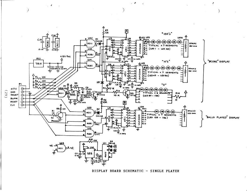
DISPLAY BOARD SCHEMATIC - SINGLE PLAYER

fo
a
1 CIO
CI2
U2 m R6
00
ca a
3 0 CI4 Q
3 i CZJD OI
Ui ICDD5
uMf4-i BFi PR cn PPi cn
PfiACicS QB
a Ba ixi a a a
aaaoD
0 qoD
n o
R»4
OI
a BB RIO
CZ CI 1=3 = 4
RGl
a a a a a a a
as
a a a a a a a
aaaaa cues E g
1 - ^ a
nRi2
<NPT . VU»)
aa a a a aa aaaaaaa
c« a D4
aaaaasa a a a
a
aaaaaa a a a a a a R7ACK1 . 1 P R a a a a a a a a a a a a a a a a a a a a a
a a a a a
aaaaaaa
DISPLAY BOARD PARTS LAYOUT - SINGLE PLATER
>

SINGLE PLAYER DISPLAY BOARD PARTS LIST
QTY COMPONENT DESCRIPTION SYMBOL SM PN
2 CAPACITOR .01 MFD 50 V o l t Ceramic C4,5 50191 9 CAPACITOR .1 MFD 50 V o l t Ceramic 03,7,8,9,10, 50094
11,13,14,15 1 CAPACITOR .22 MFD 50 V o l t Ceramic C2 50133 1 CAPACITOR 10 MFD 16 V o l t E l e c . C6 50096 1 CAPACITOR 47 MFD 16 V o l t E l e c . C12 50193 1 CAPACITOR 1000 MFD 35 V o l t E l e c • C I 1 CONNECTOR 6 PIN RT.ANGLE HEADER P I 5 DIODE 1N914 DIODE Dl,2,3,4,5 2 IC 555 TIMER U9, 10 3 IC ULN2004A ARRAY DRIVER U12,13,14 1 IC 4011 QUAD "NAND" GATE U2 1 IC 4017 U l l 1 IC 4081 QUAD "AND" GATE U l 3 IC 4510 U3,4,5 3 IC 4511 U6,7,8 1 IC 7815 REGULATOR RGl
166 L.E.D. Red E m i t t e r LEDl t h r u LEDl66 11 RESISTOR lOK ohm 5% 1/4 Watt Rl,2,3,4,5,6, 50050
7 ,8,9,12,13 1 RESISTOR 47K Ohm 5% 1/4 Watt R l l 1 RESISTOR lOOK ohm 5% 1/4 Watt RIO 1 RESISTOR 1 Meg Ohm 5% 1/4 Watt R14 1 RESISTOR 11 Ohm 1 Watt Carbon R15 2 RESISTOR PAK 100 Ohm Network Rpack 1,2 1 RESISTOR PAK 220 Ohm Network Rpack 3 2 TRANSISTOR PN2222A Ql,2 1 TRANSISTOR TIP132A Q3
(31)


TICKET COUNTER DRIVER BOARD LAYOUT
I r
(33)

TICKET COUNTER DRIVER BOARD PARTS LIST
QTY COMPONENT DESCRIPTION SYMBOL SM PN
1 CAPACITOR .01 MFD 50 V o l t Ceramic C6 50191
1 CAPACITOR .1 MFD 50 V o l t Ceramic C4 50094
2 CAPACITOR 1 MFD 16 V o l t Tantalum 10% C 2, 5
2 CAPACITOR 10 MFD 16 V o l t Tantalum C 3, 7
1 CAPACITOR 2200 MFD 25 V o l t E l e c . C I 50127
1 CONNECTOR 6 PIN LOCKING HEADER P I 50206
1 DIODE 1N914 D2 50082
2 DIODE 1N4001 D 1, 3 50048
1 IC 555 TIMER U l 50081
1 IC 7805 REGULATOR RGl 50046
1 RESISTOR 330 Ohm 5% 1/4 Watt R4 50117
3 RESISTOR lOK Ohm 5% 1/4 Watt Rl,2,3 50124
1 RESISTOR lOOK ohm 5% 1/4 Watt R6 50087
1 RESISTOR 470 ohm 1/2 Watt R5
1 TRANSISTOR TIP31 Ql 50236
(34)

0 2 C
6
D2 D l
DO 1 ^ 0 3
C I
^ 0 J B ^
c
R l R2
PARTS LAYOUT
CREDIT COUNTER DRIVER BOARD
(35)

CREDIT COUNTER DRIVER BOARD PARTS LIST
QTY COMPONENT DESCRIPTION SYMBOL SM PN
1 CAPACITOR .1 MFD 50 V o l t Ceramic C I 50094
1 CONNECTOR 5 PIN LOCKING HEADER P I 50203
1 DIODE 1N914 . D l 50082
1 DIODE 1N4001 D2 50048
1 RESISTOR 4.7K Ohm 5% 1/4 Watt R3 50086
2 RESISTOR lOK Ohm 5% 1/4 Watt Rl,2 50124
2 TRANSISTOR PN2222A Ql,2 50084
1 TRANSISTOR TIP32A Q3 50134
(36)

I?
P A R T Ma QTY. D C S C R I P T I O W
50895 1 50Ltk)6lO no V A C 1 BALL R C L L A S E: LOCK ASS*Y.
60 O O \ \ I / 8 « 1 L G C O T T E R K E Y
60522 \ x i V : ^ S P R I K I G
Z22I \ B A L L R E L E A S E P I V O T A S S T .
6 0>E0 Z I/il-E.S>^V% PHIL. PAN MO. M.S. \ B A L L R E L E A S E
0 - 7 8 9 A B R A S S BUSHmG 60082 A VB F L A T W A S H E R
60000 5 l/^e K 3 ^ C X I T T E R K E Y
2254 \ C O K ) K ) E C T A R M A S S ' Y .
e I 58 \ A D . ) U S T H E M T P I V O T
2 1 56 \ C O M M E C T I W G R O D
21 57 1 S O L E M D I D B R A C K E T
€0321 6
P H I L . P A K J MD. M . S .
60046 6 Ho. 10 L O C K - W A S H E R
LO
SMAR T BALL-IC FT A 13 FT BALL RELEASE ASSEMBLY
60213 2163
A 1
MO. e^-^ PHIL.P-HD.P.E.S. SMART BALL RAIL
60213 2162
— 5 1
MO. 6*34 PHIL. P HD. P. B.S. SMART BALL RAIL
PAfa MO lO'QTY 13'QTY. PESCRIPTIOM
6 0 0 9 7
6 0 0 0 4
6 0 1 4 7
6 0 S 3 I
6 0 3 3 O
6 0 0 I 8
6 0 0 I 9
6 O 0 7 I
6 0 2 4 3
2 2 7 0
6 0 2 6 5
PART Mo.
MO. 10-32 LOCK-UUT Mc FLAT WASHER MO. 10-24 HEX. LOCK MUT EYE BOLT 10-24 3 > i TURK) BUCKLE J^-20 HEX. MUT
SPLIT WASHER '/4 FLAT WASHER BRASS BUSHIMG BALL RELEASE STOP ASS^Y. 1^-20* I M HEX. HD. H. S.
QTY. DtSCRlPTIOM SMART IND. CORP., MFG.
1626 Delawere Ave Des Moines, Iowa 50317 2535

S PI
8
%9 i(
i'
r4€i4 «. oiOMX ex»to%
A«CM400t. erNCtt 44C M4»r4.
re ncicr MM
'*^^'«ITN LOaiC MeuTtCOMPONKNTt IN eOTTCO UNCt ANC OMITTCe / 41 It JUNACNCe TO ta. D E L T R O N I C LABS INC.
r-TJwixr/8 T M - 4 T I C K . OlSP. BOARD
O N E P U L S E ONC T'"fL^

T I C K E T S KAUST WAVE NOTCHES BETvaeEN EACH TICKET
ROLLER TENSION S P R I N G
T I C K E T QUIDE SPRING
E.
3.
4 .
T I C K E T LOADING DlPFCTIQMS; ENTER TICKETS AS INDICATED AND F E E D TICKETS PAST THE T ICKET GUIDE SPRING UNTIL. THEV STOP.
P L A C E P INGERS AS INDlCATEO AND S Q U E E Z E , THIS O P E N S THE F E E D R O L L E R S .
F E E D T I C K E T S UNTIL THE F IRST T ICKET P R O T R U D E S APPROX. l/IG* BEYOND THE DISPATCH SLOT. R E L E A S E ROLLERS. T I C K E T D I S P E N S E R IS NOVJ LOADED AND READY F O R U S E .
( 3 9 )
<1 /o^ i
-ruEp ATTATLH ftour N E T et iRs AMti XA^STALL f^os>r o c r TO E/o^u?c p i i o ? ^ P IT . k/ttr p e w o v c FzourioerAIOD SiOc rjcTS /Ms;x> ^£cotfe p o r SHIPJ IACATT.
(
1 or/. tow*} ^2i3 *cv«yv' P&. 9c8e«-
V /
5 2 6\oe tjer AisY
i
4-A
dEA^aLiAic of NoLZk L€FT B y SCtP T>AP ^tftCMJS.
" 1 a | 1 1 333122311311 HHKS!IIi!E3HHii
SMART IND. CORP., MFG. 1626Detaww9Av9. OetMolnt. Iowa 50317 V E ^ O T H E W S P E C : ALL DIMENSIONS IN INCHES
TOL:FRACTiDNAL ±Vn ANGULAR. ±y
DECIMAL: (XX ±.03
HIS PRINT ) MCAJT MBT t^. jAXAArtoo hwi
B L„/ J | r r r : . 1. -2lt5 "

ASSEMBLY TWyTBUCTIOWS
1. The " e l l e y " shipping s k i d has been designed \o perform s s s n assembly f i x t u r e . The f i r s t s t e p i n ssscmbly i s t o pr e p a r s t h s c o n t r o l console cabinet, hove the c o n t r o l c o n s o l e c a b i n e t t o t h e a r e a of d e s i r e d f i n a l l o c a t i o n . Uncrate t h e c o n t r o l c o n s o l s c a b i n e t and l a y i t on i t ' s back. I n s e r t t h e two, 1 1/4* s g u a r s s t e e l l e g s i n t o the holes provided through t h e f l o o r s t the r e a r of t h e c o n t r o l console. Align the b o l t h o l e s w i t h t h e h o l e s through the s i d e s of the con t r o l console and f a s t s n w i t h 5/16-18 X 2 1/2 c a r r a i g e bolta. I n s t a l l t h s b o l t s from t h s o u t s i d s , p o s i t i o n i n g t h s nuts on the i n s i d e of the c a b i n e t . T i g h t e n v e r y s e c u r e l y .
a . Move the a l l e y i n t o p o s i t i o n s p p r o x i s a t s l y f i v s f e e t i n f r o n t o f t h e c o n t r o l console cabinet. Remove the p l a s t i c wrap. Remove a l l u p r i g h t supports, s i d e end top c r a t i n g from t he a l l e y s h i p p i n g s k i d . Unload a l l itams placad on tha a l l e y f o r t r a n s i t . VERY IKPORTAMT: Banaath tha fr o n t end of t h e a l l e y , centered between t h e two black f r o n t a l l a y supports, s 2 x 4 has bean n a i l -•d t o t h e e k i d . Pry t h l a 2 x 4 f r o s the s k i d . Removs t h s s t s s l banding s t r a p s securing the r e a r end of the a l l e y t o the s k i d . ( R e f e r t o the eccospaning i l l u s t r a t i o n s t o c l a r i f y i n s t r u c t i o n s . ) B l i d s t h s a l l e y forward, approximataly 1 1/2 i n c h a s , u n t i l t h e Re a r A l l e y Support (on skid) i s 1/2 sxpossd. P i c k t h s c o n t r o l c o n s o l s c a b i n s t up, r o t a t i n g i t ovar t h s l a g s and p l a c a t h s f r o n t edge on the exposed area of tha Rear A l l e y Support. J o i n t h e cont r o l c o n s o l e c a b i n e t t o the a l l e y u s i n g two 1/2-13 x 3" B s c h i n s b o l t s s u p p l i e d .
B. Three ha r n e s s connections a r s r e q u i r s d t o a a k s your Smart B a l l gama o p e r a t i o n a l . A thraa pin MOLZX connector i s u t i l i z s d t o c o n n s c t the B a l l Count Switch. T h i s c o n n e c t i o n i e l o c a t e d beneath the p l a y i n g f i e l d on the r i g h t s i d e o f the c o n t r o l cons o l e . The s i g n a l harness i s routed on the l e f t s i d e of the a l l e y w h i l e the "AC" harness i s routed on the r i g h t s i d e of the a l l e y . The c o n t r o l console portion and t h s s l l s y p o r t i o n of t h e s s h a r n -• • • a s a r s j o i n e d with connectors approximately 18 inches from t h e a l l e y f a c e p l a t e . For shipping purposes, t h a c o n t r o l consolo h a r n s s s s s a r e r e s t r a i n e d i n the lower p o r t i o n of the console w i t h w i r e t i e s . Remove the shipping w i r s t i e s and d r e s s both h a r n s s s s s through the holes provided i n the c o n t r o l c o n s o l e end a l l e y f a c e p l a t e s . J o i n the connectors on both h a r n e s s e s .
4. I n s t a l l the s i d e net frames. Usa t h r e e #8 x 3/4" p a r t i c l e board screws t o a t t a c h the frame t o t h e c o n t r o l console.
. FRONT NET; The f r o n t net i s sn a v a i l a b l e o p t i o n . Assembly i n s t r u c t i o n s f o r t h i s option a r s i n c l u d e d i n t h i s manual.
5. T h i s completes assembly. The POWER SWITCH i s l o c a t e d i n t h e l e f t f r o n t corner of the upper p o r t i o n o f t h e c o n t r o l cons o l e . Plug the game i n t o the power l i n e s o urce and t u r n t h e power s w i t c h on. R e - i n s t a l l the Marque P l a s t i c .
(7)

4
.J,

\ 1 S : a a K\a*,U9* Q 1 € : 2 c riml.A.gV*' 3 G


.T
•V ...
ir'-
s i f i l l ? > ^ o
a 5 5
f
• •
• • • • •
• •
•
•
J > ' l LI • • •
•
•
• • • • •
• •
• • • •
•
• • •
•
•
• •
•
•
•
• • • •
• •
f t 'A,
s f
I -I j r
I
i f
a

SMARTBALL SCORING MODIFICATION INSTALLATION
MECHANICAL CHANGES
1) S l i d e t h e S c o r i n g Board o u t o f t h e S c o r i n g C a b i n e t and s e t away from game.
2) Remove t h e w i r e s w h i c h a r e connected t o t h e S c o r i n g m i c r o s w i t c h e s .
3) P u l l t h e Thermal S c o r i n g Trough o u t o f t h e game. ( F i g u r e 1)
4) The Thermal S c o r i n g Trough needs t o be moved 1 " t o t h e l e f t . Draw a l i n e on t h e t h e r i g h t s i d e o f b o t h Trough M o u n t i n g Boards marking t h e p o s i t i o n o f t h e Thermal S c o r i n g Trough. Remove 4 screws f r o m t h e boards and s l i d e t h e Trough t o t h e l e f t u n t i l i t measures 1 " t o t h e l e f t o f t h e l i n e s . R e i n s t a l l t h e screws f i r m l y . ( F i g u r e 2)
NOTE: I f t h e game has t h e BONUS OPTION, p a r t o f t h e L e f t Bonus S c o r i n g Trough must be trimmed o f f t o a l l o w t h e Thermal S c o r i n g Trough space f o r movement t o t h e l e f t . Measure 2" i n f r o m t h e c e n t e r on t h e f r o n t s i d e o f t h e L e f t Bonus S c o r i n g Trough. T r i m o f f t h e wood p i e c e f r o m t h e t r o u g h a t a 45 degree a n g l e t o w a r d t h e c e n t e r / r e a r o f t h e S c o r i n g C a b i n e t . ( F i g u r e 1 and F i g u r e 3) MAKE NO MODIFICATION TO THE RIGHT BONUS SCORING TROUGH!
5) P l a c e t h e Thermal S c o r i n g Trough back i n t h e game.
6) Set t h e S c o r i n g Board so t h e t o p i s f a c i n g up and t h e f r o n t i s f a c i n g away. Mount t h e S c o r i n g M i c r o s w i t c h B r a c k e t so t h e r i g h t edge o f t h e b r a c k e t i s f l u s h w i t h t a p e r e d edge o f t h e S c o r i n g Holes and 3/4" f r o m t h e bottom. T h i s s h o u l d a l l o w t h e M i c r o s w i t c h A c t u a t o r Wires t o a l i g n i n t h e c e n t e r o f t h e S c o r i n g H o l e s . I f t h e w i r e s a r e n o t c e n t e r e d , make t h e a d j u s t m e n t s t o a c c o m p l i s h t h i s t a s k . ( F i g u r e 4a)
ELECTRONIC CHANGES
1) Remove t h e P l a s t i c Marque, Back Door and Back Cover f r o m t h e game. ( F i g u r e 5)
2) Remove t h e 2 screws h o l d i n g t h e D i s p l a y Assembly. P u l l t h e D i s p l a y Assembly o u t o f t h e game and l e t t h e assembly hang i n f r o n t o f t h e game. T h i s p r o v i d e s access t o t h e Component Board Assembly.
3) Mount t h e S c o r i n g I n t e r f a c e Board n e x t t o t h e 8031 Game Board w i t h t h e c o n n e c t o r t o w a r d s t h e r e a r o f t h e game. ( F i g u r e 6 and F i g u r e 8)
4) Remove t h e e x i s t i n g m i c r o s w i t c h e s f r o m t h e Thermal S c o r i n g Trough.
5) Trace t h e m i c r o s w i t c h c a b l e u n t i l a 9 p i n molex c o n n e c t o r , l o c a t e d i n t h e r e a r o f t h e S c o r i n g Cabinet, i s f o u n d . Unplug t h e c o n n e c t o r and remove t h e f o l l o w i n g c a b l e s f r o m t h e game: ( F i g u r e 7)
1) The c a b l e f o r t h e S c o r i n g m i c r o s w i t c h e s . 2) The c a b l e f o r t h e B a l l Counter m i c r o s w i t c h . 3) The c a b l e s f o r t h e Bonus m i c r o s w i t c h e s i f t h e game has t h e
Bonus O p t i o n . A l l o f t h e s e c a b l e s a r e a t t a c h e d t o t h e 9 p i n c o n n e c t o r . Leave t h e o t h e r end o f t h e c o n n e c t o r f o r hookup l a t e r i n t h e i n s t a l l a t i o n o f t h e r e v i s i o n .
7) Route t h e s u p p l i e d c a b l e t h r o u g h t h e h o l e i n t h e back o f t h e game. Complete t h e f o l l o w i n g c o n n e c t i o n s : ( F i g u r e 7)
1) P l u g t h e 12 p i n connector i n t o S c o r i n g I n t e r f a c e Board. 2) P l u g t h e 9 p i n connector i n t o t h e c o n n e c t o r l e f t d u r i n g
r e m o v a l o f t h e o l d c a b l e s . 3) P l u g t h e 3 p i n connector i n t o t h e B a l l Count m i c r o s w i t c h
c o n n e c t o r . 4) Connect t h e Bonus m i c r o s w i t c h e s i f a p p l i c a b l e .
8) W i r e t i e t h e c a b l e s t o g e t h e r .
9) R e i n s t a l l t h e D i s p l a y Assembly.
10) Route t h e S c o r i n g c a b l e down t h e r i g h t s i d e o f t h e S c o r i n g C a b i n e t . Rest t h e S c o r i n g Board on t h e A l l e y and connect t h e S c o r i n g c a b l e t o t h e m i c r o s w i t c h e s mounted on t h e S c o r i n g Board i n t h e f o l l o w i n g manner: ( F i g u r e 4b)
1) 1 B l a c k w i r e t o each m i c r o s w i t c h . 2) The Brown w i r e t o t h e 50 p o i n t s w i t c h . 3) The Y e l l o w w i r e t o t h e 40 p o i n t s w i t c h . 4) The Green w i r e t o t h e 30 p o i n t s w i t c h . 5) The Blue w i r e t o t h e 20 p o i n t s w i t c h . 6) The V i o l e t w i r e t o t h e 10 p o i n t s w i t c h .
11) R e i n s t a l l t h e P l a s t i c Marque, Back Door and Back Cover.
12) R e i n s t a l l S c o r i n g Board. CAUTION MUST BE USED TO PREVENT DAMAGE TO THE SCORING MICRO-SWITCHES.

PARTS LI S T
QUANTITY DESCRIPTION PART NUMBER
1 Cable Assembly 3441 1 S c o r i n g I n t e r f a c e Board 3419 1 S c o r i n g S w i t c h B r a c k e t 3423 5 M i c r o - s w i t c h a c t u a t o r s 3424 5 M i c r o - s w i t c h e s 50297 3 #8 X 3/4" screws 60213 4 White c i r c u i t b oard s t a n d o f f s 60062 4 B l a c k c i r c u i t b o ard s t a n d o f f s 60091 4 C i r c u i t board mounting screws 60017 20 5 1/4" w i r e t i e s 60112

F i g u r e 1


Back of Cabinet
L e f t Bonus Scoring Trough
/
/ 2" T
Mark and c u t o f f corner
2" ^
TOP VIEW
NOTE: Ri g h t Bonus Scoring Trough r e q u i r e s no m o d i f i c a t i o n .
F i g u r e 3

COMPONENT BOARD ASSEMBLY
Rear _P o
DBA C o n t r o l l e r (Option)
1 I
S c o r i n g I n t e r f a c e ! Board
8031 Board
Fro n t
P l a c e t h e Sco r i n g I n t e r f a c e Board between the 8031 Game Board and the DBA C o n t r o l l e r with the connector f a c i n g toward the r e a r of the game.
Figure 6

F l u s h b r a c k e t w i t h tapered o u t s i d e edge of hole.
Back s i d e of Sc o r i n g Board
3/4"
Figure 4a
S i g n a l (Other c o l o r )
Common (Black)
Micro-switch
Figure 4b

Back Door
Figure 5

12 p i n connector t o S c o r i n g I n t e r f a c e Board
V
S c o r i n g Cable S t a p l e and w i r e t i e t o r i g h t s i d e of Cabinet
To m i c r o - s w i t c h e s
Run Cable behind game and w i r e t i e t o other c a b l e s
Bonus Cables S t a p l e and wire t i e t o back of Cabinet
9 p i n connector
B a l l Count Cable S t a p l e and w i r e t i e t o r i g h t s i d e of Cabinet
3 p i n connector
Figure 7