Embed Size (px)
Citation preview

Pictures are not contractual NT-BFDE(V1-EN) – V1 – 02/06
MANUAL FOR THE INSTALLATION AND MAINTENANCE OF
FIXED ENERGY SUPPLY BOLLARDS (a.k.a. BFDE)
Article Code: DFE… and DFO…
THIS MANUAL IS INTENDED FOR TECHNICAL STAFF IN CHARGE OF THE INSTALLATION, OPERATION AND MAINTENANCE OF THESE PRODUCTS.
ELECTRIC SHOCK HAZARD

Manual for the installation and maintenance of fixed energy supply bollards
Engineering Division – URBACO - 2 -
CONTENT 1. GENERAL FEATURES......................................................................................................................... 3
2. DESCRIPTION ...................................................................................................................................... 4 2.1. BFDE – Simple Unit...................................................................................................................... 4 2.2. BFDE – Double Unit ..................................................................................................................... 5
3. ELECTRICAL SPECIFICATIONS......................................................................................................... 6 3.1. Protection degree ......................................................................................................................... 6 3.2. Specifications for power supply .................................................................................................... 6 3.3. Specifications of electrical protections in boxes (enclosures)....................................................... 6 3.4. Specifications of electrical sockets used ...................................................................................... 7
4. HYDRAULIC SPECIFICATIONS .......................................................................................................... 8
5. INSTALLATION AND START-UP ........................................................................................................ 9 5.1. Roadwork...................................................................................................................................... 9 5.2. Embedding plan for the BFDE...................................................................................................... 9 5.3. BFDE / Installation ...................................................................................................................... 10 5.4. Electrical connections ................................................................................................................. 10 5.5. Connection to local water system............................................................................................... 10 5.6. BFDE / Start-up .......................................................................................................................... 10
6. HOW TO USE THE BFDE? ................................................................................................................ 12 6.1. Conditions of use........................................................................................................................ 12 6.2. Opening the BFDE...................................................................................................................... 12
7. MAINTENANCE AND CHECK-UPS ................................................................................................... 13 7.1. Calendar for maintenance operations......................................................................................... 13 7.2. Description of check-up procedures ........................................................................................... 13
8. TABLE OF ARTICLE CODES ............................................................................................................ 14

URBACO – S.A.
URBACO S.A. - 3 -
1. GENERAL FEATURES The Fixed Bollard for Energy Supply has been designed to make multiple connections easily, be it for power and/or for water according to model purchased. For low voltage, 3 socket types are available: 16 amps, 32 amps and 63 amps. Each socket is individually protected by a RCBO / GFCI breaker 30 milliamps calibrated according to the socket. For water supply, only one type of ball valve is available. The great resistance of the fixed bollard for power supply allows durable exposure in public areas. To give the fixed bollards the highest finishing standard, all materials used for their compositions are of the best quality available. Two models of fixed bollards are available: - BFDE Simple unit: up to 6 sockets of 16 amps or up to 4 valves. - BFDE Double unit: up to 12 sockets of 16 amps and 4 valves. See our catalogue for the various versions. Applications: Market places, pedestrianised streets, show grounds, trade fairs, leisure parks, sports and concert arenas, campsites, RV/caravans parks, technical division facilities and workshops, parking lots, airport grounds, reception centres... Thank you for choosing an URBACO® fixed bollard for power supply; it has been carefully designed according to rigorous specifications to ensure maximum quality and solidity. It will best serve your needs and be operational for a long time if all instructions for installation, directions for use and maintenance are carefully respected. This bollard has received official homologations for use in severe conditions of operation. The alteration of a structural part, control or command actuators, will result in decreased reliability and create potential hazard for users. If installation instructions and maintenance terms are not respected, the life span of your fixed bollard for power supply will be shortened. The safety of users depends on the full respect of all elementary rules of maintenance. This manual is mostly intended to help you install, connect and use your fixed bollard for power supply It uses warning signs and symbols as these pictographs:
Manual for the installation and maintenance of fixed energy supply bollards
Engineering Division – URBACO - 4 -
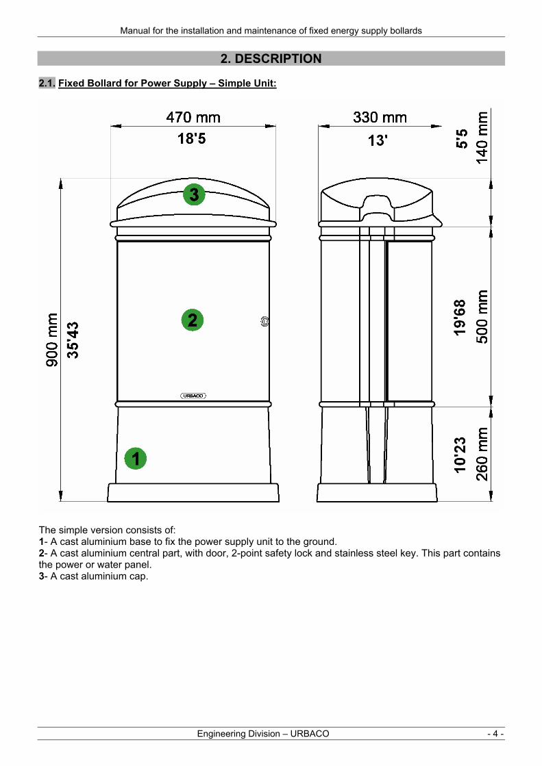
2. DESCRIPTION 2.1. Fixed Bollard for Power Supply – Simple Unit:
The simple version consists of: 1- A cast aluminium base to fix the power supply unit to the ground. 2- A cast aluminium central part, with door, 2-point safety lock and stainless steel key. This part contains the power or water panel. 3- A cast aluminium cap.

URBACO – S.A.
URBACO S.A. - 5 -
2.2. Fixed Bollard for Power Supply – Double Unit:
This double unit version consists of: 1- A cast aluminium base to fix the power supply unit to the ground. 2- A lower part in cast aluminium, door with 2-point safety lock and special stainless steel key. This part contains the electrical panel, the water valves or the electricity or water meters. 3- An upper part in cast aluminium, door with 2-point safety lock and special stainless steel key. This part contains the electrical panel. 4- A cast aluminium cap.

Manual for the installation and maintenance of fixed energy supply bollards
Engineering Division – URBACO - 6 -
C16
C32
C63 + C2 + CT
3. ELECTRICAL SPECIFICATIONS 3.1. Protection degree: In compliance with article 212 of CEI 439-1 as per CEI 529:
- IP44 for the sockets - IP20 for the circuit breaker compartment when its protective cap is open.
3.2. Specifications for power supply: Voltage:
3-phased 400V + neutral + earth (ground) Current frequency:
AC 50Hz Cable between the BFDE and the general switchboard (not supplied):
U1000RO2V (number of conductors and section according to layout) Cable from BFDE (supplied):
H07RNF with 5 conductors, length 6 metres, connected in the electrical box. 3.3. Specifications of electrical protections in boxes (enclosures): In compliance with NF EN 61009-1 standard. Protection for 2P+E 16A socket: GFCI /circuit breaker such as Legrand’s DNX 1Phase+Neutral (or similar) Rated AC amperage: 16 A Breaking capacity: 4.5kA – IEC 60947-2 - 230V~ GFCI: 30mA AC type Protection for 3P+N+E 32A socket: GFCI /circuit breaker such as Legrand’s DX 4P (or similar) Rated AC amperage: 32A Breaking capacity: 10kA – IEC 60947-2 - 400V~ GFCI: 30mA AC type Protection for 3P+N+E 63A socket: GFCI /circuit breaker such as Legrand’s DX 4P (or similar) Rated AC amperage: 63A Breaking capacity: 10kA – IEC 60947-2 - 400V~ GFCI: 30mA AC type

URBACO – S.A.
URBACO S.A. - 7 -
BT16
BT32
BT63
Example of an electrical case: 4 sockets 2P+E 16A 1- IP55 plastic box (case) 2- Sockets 2P+E 240V 16A 3- Transparent protection shutter 4- GFCI’s 16A 30mA 5- Power cable (6m supplied) 6- Cable gland
1
2
3 4
5
6
3.4. Specifications of electrical sockets used: In compliance with CEI EN 60309-1-2 standards and the decree from 14 Nov. 1988 relating to the safety of workers. Socket 2P+E 200/250V 16A such as Legrand’s HYPRA BT16A (or similar) Type: angled socket outlet Pin / Clock face position: 6 o’clock Material: Plastic Protection degree: IP 44 Rated operating voltage: 240V~ single-phased + earth Rated AC amperage: 16A Socket 3P+N+E 380/415V 32A such as Legrand’s HYPRA BT32A (or similar) Type: angled socket outlet Pin / Clock face position: 6 o’clock
Material: Plastic Protection degree: IP 44 Rated operating voltage: 400V~ 3-phased + neutral + earth Rated AC amperage: 32A Socket 3P+N+T 380/415V 63A such as Legrand’s HYPRA BT63A (or similar) Type: angled socket outlet Pin / Clock face position: 6 o’clock
Material: Plastic Protection degree: IP 44 Rated operating voltage: 400V~ 3-phased + neutral + earth Rated AC amperage: 63A

Manual for the installation and maintenance of fixed energy supply bollards
- 8 -
Shut-off valve with drain plug
Check valve
Example of a water supply panel: 4 valves 1- Valve for users 2- Shut-off valve with drain plug 3- Check valve (rear side)
1
2
3
4. HYDRAULIC SPECIFICATIONS Fixed bollards for water supply are fitted with a shut-off valve with drain plug located in the lower part of the unit. A check valve is also available to prevent any contamination risk of drinking-water system. Characteristics: Maximum allowable pressure value: 20 bar Inner diameter of pipes: 15 mm Equipment: 2 or 4 ¼-turn service taps (Ø ½’’ – 15x21) Connections: Shut-off valve must be connected directly onto the water supply system. Male threaded connector Ø ½’’ – 15x21. Hosepipes provided by users are plugged onto the valve or with quick connects (not supplied). It is not possible to shut the door while the unit is being used. Male threaded connector Ø ½’’ – 15x21. .
URBACO – S.A.
Service Ingénierie – URBACO - 9 -
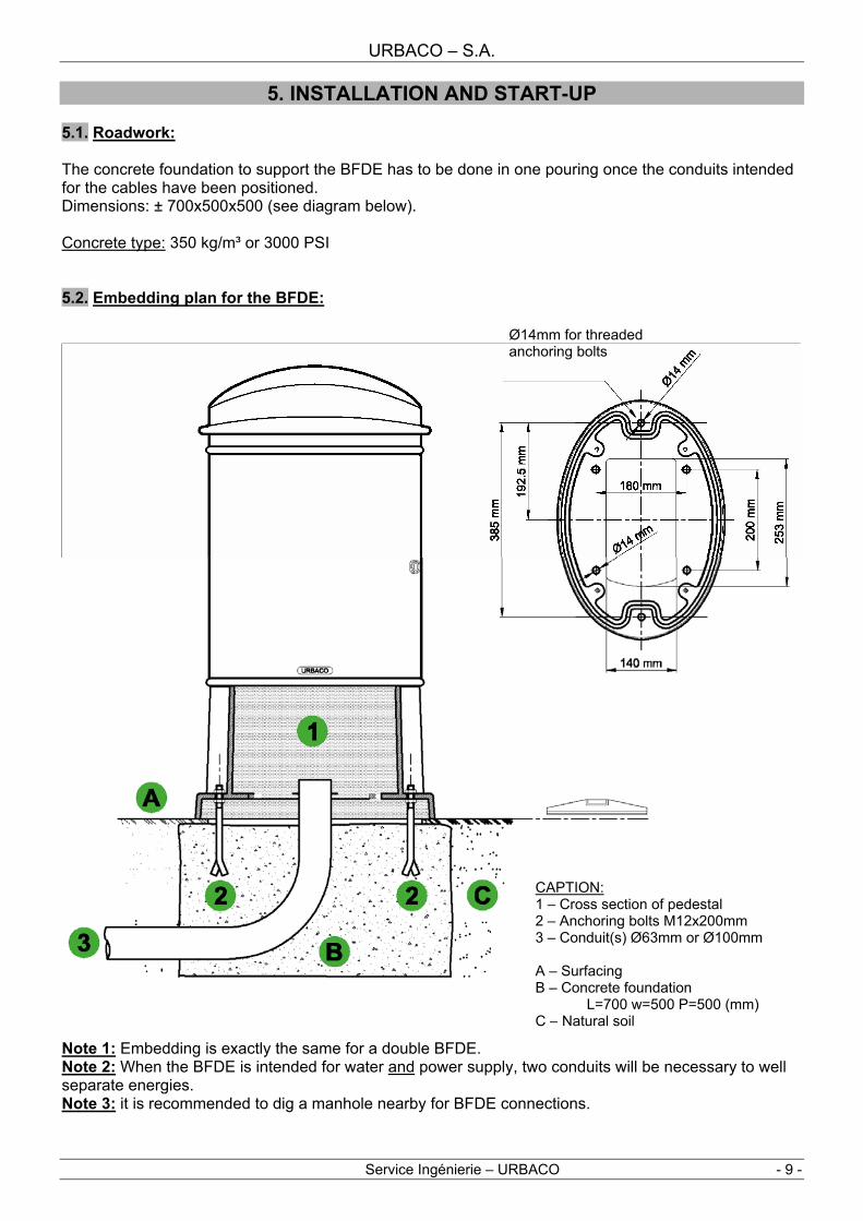
CAPTION: 1 – Cross section of pedestal 2 – Anchoring bolts M12x200mm 3 – Conduit(s) Ø63mm or Ø100mm A – Surfacing B – Concrete foundation
L=700 w=500 P=500 (mm) C – Natural soil
Ø14mm for threaded anchoring bolts
5. INSTALLATION AND START-UP 5.1. Roadwork: The concrete foundation to support the BFDE has to be done in one pouring once the conduits intended for the cables have been positioned. Dimensions: ± 700x500x500 (see diagram below). Concrete type: 350 kg/m³ or 3000 PSI 5.2. Embedding plan for the BFDE:
Note 1: Embedding is exactly the same for a double BFDE. Note 2: When the BFDE is intended for water and power supply, two conduits will be necessary to well separate energies. Note 3: it is recommended to dig a manhole nearby for BFDE connections.

Manual for the installation and maintenance of fixed energy supply bollards
- 10 -
5.3. BFDE / Installation: Before unpacking / unwrapping: Prior to cutting straps which hold the BFDE on its pallet, make sure the material received is well positioned on the pallet and / or that the pallet is not damaged / broken.
Use the appropriate lifting tools to properly position the BFDE. 5.4. Electrical connections: The BFDE is fitted with a H07RNF type cable which will be coupled to the cable going to the low voltage general panel via a proper sealed junction box (not supplied). This junction box may also be lodged inside the cast iron pedestal although the cable length (6 m supplied) also enables to lodge that box inside a manhole located near the BFDE. A technical data sheet is included together with this manual. It contains all specific characteristics of the BFDE chosen (embedding, wiring diagram…).
It is imperative that all electrical wiring be done with all due protection by qualified wiremen.
5.5. Connection to local water system: The shut-off valve is directly connected onto the water inlet. Male threaded connector Ø ½’’ – 15x21 5.6. BFDE – Start-up: When the BFDE has been installed and all connections made, you are ready to proceed with start up once the following points have been checked:
Control procedure to respect before any start up.
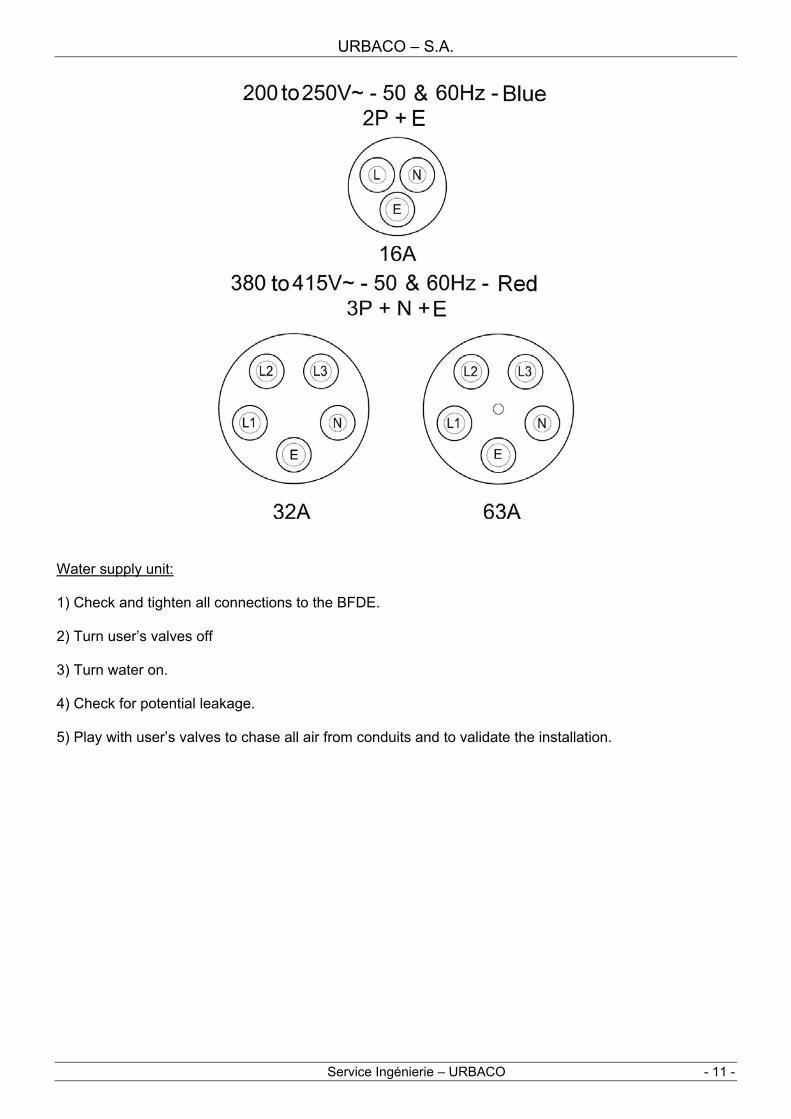
Power supply unit: 1) Check that the cable is properly earthed and has not been damaged during installation. 2) Make sure, once everything is unplugged, there is no short circuit between the various conductors at main circuit breaker level. 3) Energize and check with test button that each GFCI /circuit breaker of the BFDE is operational. 4) For BFDEs with a 63A socket, do a disconnection test with a 63A plug where the neutral terminal is connected to the pilot terminal. Plugging in should trigger the corresponding contactor (mechanical warning indicator visible on the front plate of the contactor. 5) Make sure using the appropriate tools that voltage supplied to each contact are in compliance with the CEE-clock installation diagram of CEI 60 309-2 (see diagrams below).
URBACO – S.A.
Service Ingénierie – URBACO - 11 -
Water supply unit: 1) Check and tighten all connections to the BFDE. 2) Turn user’s valves off 3) Turn water on. 4) Check for potential leakage. 5) Play with user’s valves to chase all air from conduits and to validate the installation.

Manual for the installation and maintenance of fixed energy supply bollards
- 12 -
6. HOW TO USE THE BFDE? 6.1. Conditions of use: The power supply unit can tolerate drizzly weather even when the door(s) is (are) open as it is IP 44 protected. The transparent cover for the GFCI / circuit breaker compartment (2) should only be opened under certain weather and environment conditions (IP 20). With the cable gland option, the door may be shut even with cables still connected. The use of the water supply unit is not subject to any particular weather or environmental condition. Note: for mixed BFDEs supplying power (top module) and water (bottom module), a physical separation is inserted between both modules. 6.2. Opening the BFDE: A key (3) is necessary to open the door(s) and access power sockets, circuit breakers and water valves.

URBACO – S.A.
Service Ingénierie – URBACO - 13 -
7. MAINTENANCE AND CHECK-UPS 7.1. Calendar for maintenance operations:
Check-up Points
Check-up and maintenance of electrical
components 1st mon
th
2nd m
onth
3rd m
onth
4th mon
th
5th mon
th
6th mon
th
7th mon
th
8th mon
th
9th mon
th
10th
month
11th m
onth
12th m
onth
1 Check-up of sockets
2 Check-up of
circuit breakers
3 Check-up of GFCI /
circuit breakers
4 Insulation
5 Control by
authorised body Yearly
Check-up Points
Check-up and maintenance of the water
supply compartment 1st mon
th
2nd m
onth
3rd m
onth
4th mon
th
5th mon
th
6th mon
th
7th mon
th
8th mon
th
9th mon
th
10th
month
11th m
onth
12th m
onth
6 Check-up of valves
7 Leakage
If there is a risk of frost, it is recommended to drain all pipes in the BFDE to avoid conduit breaking.
7.2. Description of check-up procedures: 1- Check-up of sockets: Eye-check all power socket, their covers and bases. Replace faulty components. Check Test en charge de chaque prise. 2- Check-up of circuit breakers: Switch breakers on and off and check voltage. 3- Check-up of GFCI / circuit interrupters: Energize and check with test button that each GFCI /circuit breaker of the BFDE is operational. 4- Insulation: Proceed with insulation tests as stated in the directives of C15-100 standard. 5- Control by authorised body: the legislation states that all operators of any electrical system and/or appliance for public use have all equipment tested once per year by an authorised body (France) – Check what the local legislation recommends in your country. 6- Check-up of valves: Open and shut the valves to check they are working normally. 7- Leakage: Check all conduits and valves for potential leakage.

Manual for the installation and maintenance of fixed energy supply bollards
- 14 -
8. TABLE OF ARTICLE CODES
Fixed Bollards for Sockets Sockets Sockets Energy Supply
Article Code 16A 32A 63A
Valves
DFE300D1 3 --- --- --- DFE400D1 4 --- --- --- DFE600D1 6 --- --- --- DFE210D1 2 1 --- --- DFE410D1 4 1 --- --- DFE020D1 --- 2 --- --- DFE220D1 2 2 --- --- DFE030D1 --- 3 --- ---
Power supply
DFE001D1 --- --- 1 --- DFOE2P1N --- --- --- 2
SIMPLE VERSION
Water supply DFOE4P1N --- --- --- 4
DFEC00P2 12 --- --- --- DFE810P2 8 1 --- --- DFE420P2 4 2 --- --- DFE620P2 6 2 --- --- DFE630P2 6 3 --- --- DFE440P2 4 4 --- --- DFE060P2 --- 6 --- --- DFE601P2 6 --- 1 --- DFE411P2 4 1 1 --- DFE221P2 2 2 1 ---
DFE031P2 --- 3 1 ---
Power supply
DFE002P2 --- --- 2 --- DFE400P1 4 --- --- --- DFE600P1 6 --- --- --- DFE410P1 4 1 --- --- DFE220P1 2 2 --- --- DFE030P1 --- 3 --- ---
Power supplywith meter
DFE001P1 --- --- 1 --- DFE200DE2P2 2 --- --- 2 DFE600DE2P2 6 --- --- 2 DFE410DE2P2 4 1 --- 2 DFE020DE2P2 --- 2 --- 2 DFE120DE2P2 1 2 --- 2 DFE030DE2P2 --- 3 --- 2 DFE001DE2P2 --- --- 1 2 DFE400DE4P2 4 --- --- 4 DFE600DE4P2 6 --- --- 4 DFE410DE4P2 4 1 --- 4 DFE020DE4P2 --- 2 --- 4 DFE120DE4P2 1 2 --- 4 DFE030DE4P2 --- 3 --- 4
DOUBLE VERSION
Power and water supply
DFE001DE4P2 --- --- 1 4

URBACO – S.A.
Service Ingénierie – URBACO - 15 -

Manual for the installation and maintenance of fixed energy supply bollards
- 16 -
BFDEs and their components are in compliance and certified so with the following standards and directives:
- NF EN 60529-1 (OCTOBER 1992) - NF EN 60439-1 (OCTOBER 1994) - NF EN 60439-5 (AUGUST 1996) - NF EN 60204-1 (APRIL 1998) - CEI 439-1 - CEI 529 - CEI 947-2 - CEI 60 309-1 - C 15 100 - CEI 60 309-2
Type: See table §8 First released: 2006
URBACO S.A. - Z.A. du Couquiou 84320 ENTRAIGUES - FRANCE Tél : 04 90 48 08 08 - Fax : 04 90 48 00 88
Tél export : 33 4 90 48 08 00 E.mail : [email protected]