Embed Size (px)
Citation preview

MANUAL FOR HOUSING ASSEMBLY

1st edition English 02/2007Documentation © 2007 Schaeffer AG, Berlin
All rights reserved. This manual may not be reproduced in any form, in whole or in part, without the prior written approval of the publisher. It may not be copied or processed using any electronic, mechanical or chemical method.It is possible that this manual still contains printing faults or errors. How-ever, the information in it is checked regularly, and corrections will appear in the next edition. We accept no liability for technical or printing errors or their consequences. All trademarks and protected rights are acknowl-edged.
Printed in GermanyWe reserve the right to introduce modifications without prior notification, where they serve technical progress.

Page 3
Tabel Of Contents
Side section 1................................................................................................................................................4
Side section 2................................................................................................................................................5
Order numbers for side sections 1 & 2 and accessories.........................................................................6
Housing section 1..........................................................................................................................................7
Order numbers for housing section 1 and accessories...........................................................................8
Housing profile 2............................................................................................................................................9
Order numbers for housing section 2 and accessories.........................................................................10
Housing bracket...........................................................................................................................................11
Order numbers for housing brackets ....................................................................................................12
Schaeffer AG www.schaeffer-ag.deHohentwielsteig 6a, D - 14163 Berlin 06.09.2007
Page 4
SideSideSideSide section 1section 1section 1section 1
The length of the side section is the same as the length of the cover plate (G).
Side plates
Width of housing (A) = õ 30; ï 1000 mm
or (A) = Board width + 3 mm
Height of housing (B) = 42 mm
C = A – 8 mm
D = 34 mm
E = 4 mm
Material thickness = õ 2 mm
Corner radius = 2 mm
Cover plates
Cover plate length (G) = õ 20; ï 1000 mm
Material thickness (M) = õ 1.5 mm
Corner radius = 0 mm
Cover plate height (F) = A - 14.2 mm
Cut surfaces F1 (Case 1) F2 (Case 2)
Height = 3.5 mm 3.5 mm
Cut surface outside (F1) Cut surface inside (F2) Width = G + 3 mm G + 3 mm
Depth (T) = M – 1.5 mm M – 1.5 mm
Cut surface shape: rectangular rectangular
Corner radius = 1.5 mm 1.5 mm
Mill = 3 mm 3 mm
With material thicknesses >2.5 mm the cover plate overlaps the side section. It is then useful to position the cut surface inside.
Rotation angle =
On reverse side:
0° (when aligned horizontally)90° (when aligned vertically)
no yes
Setting points for the cut surfaces (horizontal alignment) F1 (Case 1) F2 (Case 2)
When the alignment is vertical the X and Y values are exchanged.
lower cut surface X = G / 2 G / 2
Y = 1.25 mm 1.25 mm
upper cut surface X = G / 2 G / 2
Y = F – 1.25 mm F – 1.25 mm
Schaeffer AG www.schaeffer-ag.deHohentwielsteig 6a, D - 14163 Berlin 06.09.2007
side panelscover panels
side profiles
printed circuit board feasible
slot width
hole ø3.2 mm orcountersinking ø2.9 mm DIN74-C
edge to fit side profile groove
The cavities are onlynecessary if materialwith a thickness of> 1.5 mm is selected.
cover panelmilled edge
cover panelmilled edge

Page 5
Side section 2Side section 2Side section 2Side section 2
The length of the side section is the same as the length of the cover plate (G).
Side plates
Width of housing (A) = õ 30; ï 1000 mm
or (A) = Board width + 3 mm
Height of housing (B) = 56 mm
C = A – 8 mm
D = 48 mm
E = 4 mm
Material thickness = õ 2 mm
Corner radius = 2 mm
Cover plates
Cover plate length (G) = õ 20; ï 1000 mm
Material thickness (M) = õ 1.5 mm
Corner radius = 0 mm
Cover plate height (F) = A - 14.2 mm
Cut surfaces F1 (Case 1) F2 (Case 2)
Height = 3.5 mm 3.5 mm
Cut surface outside (F1) Cut surface inside (F2) Width = G + 3 mm G + 3 mm
Depth (T) = M – 1.5 mm M – 1.5 mm
Cut surface shape: rectangular rectangular
Corner radius = 1.5 mm 1.5 mm
Mill = 3 mm 3 mm
With material thicknesses >2.5 mm the cover plate overlaps the side section. It is then useful to position the cut surface inside.
Rotation angle =
On reverse side:
0° (when aligned horizontally)90° (when aligned vertically)
no yes
Setting points for the cut surfaces (horizontal alignment) F1 (Case 1) F2 (Case 2)
When the alignment is vertical the X and Y values are exchanged.
lower cut surface X = G / 2 G / 2
Y = 1.25 mm 1.25 mm
upper cut surface X = G / 2 G / 2
Y = F – 1.25 mm F – 1.25 mm
Schaeffer AG www.schaeffer-ag.deHohentwielsteig 6a, D - 14163 Berlin 06.09.2007
hole ø3.2 mm orcountersinking ø2.9 mm DIN74-C
edge to fit side profile groove
The cavities are onlynecessary if materialwith a thickness of> 1.5 mm is selected.
cover panelmilled edge
cover panelmilled edge
side panelscover panels
side profiles
printed circuit board feasible

Page 6
Order numbers for side sections 1 & 2 and accessories
Order numbers for side sections 1 & 2 (Surface anodized, cut edges blank)
Designation Order – No. Remarks
Side section 1 (nature) GL GP 10 11 - ****
Side section 2 (nature) GL GP 10 21 - ****
Side section 1 (black) GL GP 10 13 - ****
Side section 2 (black) GL GP 10 23 - ****
**** corresponds to the required length in mm, min. 30 mm, max. 1000 mm. Cutting accuracy: up to 200 mm length !0.1 mm, greater lengths !0.2 mm
Accessories order numbers
An assembly kit comprises 8 ø2.9 x 9.5 mm screws in acc. with DIN 7981, 7982 or 7983 and 4 self-adhesive, black rubber feet, ø8mm, height = 2.5 mm. The screws are supplied as either nickel-plated, black or white galvanized.
A box of assorted screws contains 50 ø2.9 x 9.5 mm screws in acc. with DIN 7981, 7982 or 7983. The screws are supplied as eithernickel-plated, black or white galvanized.
The ø2.9 x 9.5 mm screws are suitable for side panel thicknesses from 1.5 to 3.0 mm.
Designation Order-No. Screws
Screws white galvanized
Assembly kit ISP / A3,0-ZI GG MS 1101 Oval head screws in acc. with DIN 7981
Assembly kit ISP / B3,0-ZI GG MS 1102 Countersunk head screws in acc. with DIN 7982
Assembly kit ISP / C3,0-ZI GG MS 1103 Oval countersunk head screws in acc. with DIN 7983
Assorted screws ISP / A3,0-ZI GG SO 1101 Oval head screws in acc. with DIN 7981
Assorted screws ISP / B3,0-ZI GG SO 1102 Countersunk head screws in acc. with DIN 7982
Assorted screws ISP / C3,0-ZI GG SO 1103 Oval countersunk head screws in acc. with DIN 7983
Screws nickel-plated
Assembly kit ISP / A3,0-NI GG MS 1111 Oval head screws in acc. with DIN 7981
Assembly kit ISP / B3,0-NI GG MS 1112 Countersunk head screws in acc. with DIN 7982
Assembly kit ISP / C3,0-NI GG MS 1113 Oval countersunk head screws in acc. with DIN 7983
Assorted screws ISP / A3,0-NI GG SO 1111 Oval head screws in acc. with DIN 7981
Assorted screws ISP / B3,0-NI GG SO 1112 Countersunk head screws in acc. with DIN 7982
Assorted screws ISP / C3,0-NI GG SO 1113 Oval countersunk head screws in acc. with DIN 7983
Screws black galvanized
Assembly kit ISP / A3,0-SW GG MS 1121 Oval head screws in acc. with DIN 7981
Assembly kit ISP / B3,0-SW GG MS 1122 Countersunk head screws in acc. with DIN 7982
Assembly kit ISP / C3,0-SW GG MS 1123 Oval countersunk head screws in acc. with DIN 7983
Assorted screws ISP / A3,0-SW GG SO 1121 Oval head screws in acc. with DIN 7981
Assorted screws ISP / B3,0-SW GG SO 1122 Countersunk head screws in acc. with DIN 7982
Assorted screws ISP / C3,0-SW GG SO 1123 Oval countersunk head screws in acc. with DIN 7983
Small screw primer (M3:1)
DIN 7981 DIN 7982 DIN 7983
DIN 7985 DIN 965 DIN 966
Schaeffer AG www.schaeffer-ag.deHohentwielsteig 6a, D - 14163 Berlin 06.09.2007

Page 7
Housing section 1Housing section 1Housing section 1Housing section 1
The length of the side section is the same as the length of the cover plate (G).
Side plates
Width of housing (A) = õ 40; ï 1000 mm
Height of housing (B) = õ 40; ï 1000 mm
C = A – 10.4 mm
D = B – 10.4 mm
E = 5.2 mm
Material thickness = õ 2mm
Corner radius = 2 mm
Deckplatten
Case 1:
Case 2:
Pair A Pair B
Cover plate length (G) = õ 40; ï 1000 mm
Material thickness (M) = õ 1.5 mm
Corner radius = 0 mm
Cover plate height (F) = A - 20.2 mm B - 20.2 mm
Cut surfaces F1 (Case 1) F2 (Case 2)
Cut surface outside (F1) Cut surface inside (F2) Height = 6.5 mm 3.7 mm
Width = G + 3 mm G + 3 mm
Depth (T) = M – 1.5 mm M – 1.5 mm
Cut surface shape: rectangular rectangular
Corner radius = 1.5 mm 1.5 mm
With material thicknesses >2.5 mm the cover plate overlaps the side section. It is then useful to position the cut surface inside.
Mill = 3 mm 3 mm
Rotation angle =
On reverse side:
0° (when aligned horizontally)90° (when aligned vertically)
no yes
Setting points for the cut surfaces (horizontal alignment) F1 (Case 1) F2 (Case 2)
When the alignment is vertical the X and Y values are exchanged.
lower cut surface X = G / 2 G / 2
Y = 2.75 mm 1.35 mm
upper cut surface X = G / 2 G / 2
Y = F – 2.75 mm F – 1.35 mm
Schaeffer AG www.schaeffer-ag.deHohentwielsteig 6a, D - 14163 Berlin 06.09.2007
cover panelspair B
cover panelspair A
side panels
profile
hole ø5.3 mm orcountersinking ø5.0 mm DIN74-A
The cavities are onlynecessary if materialwith a thickness of>1.5 mm is selected.
edge to fit sidehousing profile groove
cover panel
cavitycover panel
cavity

Page 8
Order numbers for housing section 1 and accessories
Surface of the sections anodized (cut edges are blank)
Designation Order – No. Remarks
Housing section 1 (nature)
Housing section 1 (black)
GL GP 20 11 - ****
GL GP 20 13 - ****
**** corresponds to the required length in mm, min. 30 mm, max. 1000 mm. Cutting accuracy: up to 200 mm length !0.1 mm, greater lengths !0.2 mm
Accessories
An assembly kit comprises 8 M5 x 20 mm screws in acc. with DIN 7985, 965 or 966 and 4 self-adhesive, black rubber feet, ø8 mm,height = 2.5 mm. The screws are supplied as either nickel-plated, black or white galvanized.
A box of assorted screws contains 50 M5 x 20 mm screws in acc. with DIN 7985, 965 or 966. The screws are supplied as eithernickel-plated, black or white galvanized.
The M5 x 20 mm screw is suitable for side plate thicknesses from 1.5 to 6.0 mm.
Designation Order-No. Screws
Screws white galvanized
Assembly kit IGP / A6,0-ZI GG MS 1601 Oval countersunk head screws in acc. with DIN 7985
Assembly kit IGP / B6,0-ZI GG MS 1602 Countersunk head screws in acc. with DIN 965
Assembly kit IGP / C6,0-ZI GG MS 1603 Oval countersunk head screws in acc. with DIN 966
Assorted screws IGP / A6,0-ZI GG SO 1601 Oval countersunk head screws in acc. with DIN 7985
Assorted screws IGP / B6,0-ZI GG SO 1602 Countersunk head screws in acc. with DIN 965
Assorted screws IGP / C6,0-ZI GG SO 1603 Oval countersunk head screws in acc. with DIN 966
Screws nickel-plated
Assembly kit IGP / A6,0-NI GG MS 1611 Oval countersunk head screws in acc. with DIN 7985
Assembly kit IGP / B6,0-NI GG MS 1612 Countersunk head screws in acc. with DIN 965
Assembly kit IGP / C6,0-NI GG MS 1613 Oval countersunk head screws in acc. with DIN 966
Assorted screws IGP / A6,0-NI GG SO 1611 Oval countersunk head screws in acc. with DIN 7985
Assorted screws IGP / B6,0-NI GG SO 1612 Countersunk head screws in acc. with DIN 965
Assorted screws IGP / C6,0-NI GG SO 1613 Oval countersunk head screws in acc. with DIN 966
Screws black galvanized
Assembly kit IGP / A6,0-SW GG MS 1621 Oval countersunk head screws in acc. with DIN 7985
Assembly kit IGP / B6,0-SW GG MS 1622 Countersunk head screws in acc. with DIN 965
Assembly kit IGP / C6,0-SW GG MS 1623 Oval countersunk head screws in acc. with DIN 966
Assorted screws IGP / A6,0-SW GG SO 1621 Oval countersunk head screws in acc. with DIN 7985
Assorted screws IGP / B6,0-SW GG SO 1622 Countersunk head screws in acc. with DIN 965
Assorted screws IGP / C6,0-SW GG SO 1623 Oval countersunk head screws in acc. with DIN 966
Small screw primer (M 3:1)
DIN 7985 DIN 965 DIN 966
DIN 562 DIN 934
Schaeffer AG www.schaeffer-ag.deHohentwielsteig 6a, D - 14163 Berlin 06.09.2007
Page 9
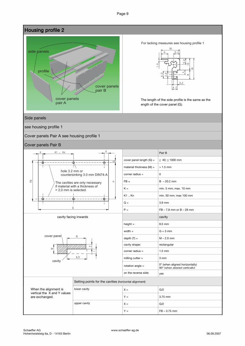
Housing profile 2Housing profile 2Housing profile 2Housing profile 2
The length of the side profile is the same as the
ength of the cover panel (G).
Side panels
see housing profile 1
Cover panels Pair A see housing profile 1
Cover panels Pair B
Pair B
cover panel length (G) = õ 40; ï 1000 mm
material thickness (M) = > 1.5 mm
corner radius = 0
FB = B – 20.2 mm
K = min. 5 mm; max. 10 mm
K1 .. Kn min. 50 mm; max 100 mm
Q = 3.9 mm
P = FB – 7.8 mm or B – 28 mm
cavity facing inwards cavity
height = 8.5 mm
width = G + 3 mm
depth (T) = M – 2.0 mm
cavity shape: rectangular
corner radius = 1.5 mm
milling cutter = 3 mm
rotation angle = 0° (when aligned horizontally)90° (when aligned vertically)
on the reverse side: yes
Setting points for the cavities (horizontal alignment)
When the alignment is vertical the X and Y values are exchanged.
lower cavity X = G/2
Y = 3.75 mm
upper cavity X = G/2
Y = FB – 3.75 mm
Schaeffer AG www.schaeffer-ag.deHohentwielsteig 6a, D - 14163 Berlin 06.09.2007
For lacking measures see housing profile 1
The cavities are only necessaryif material with a thickness of> 2,0 mm is selected.
hole 3.2 mm or3.0 mm DIN74-Acountersinking
cavity
cover panel
cover panelspair B
cover panelspair A
side panels
profile

Page 10
Order numbers for housing section 2 and accessories
Surface of the sections anodized (cut edges are blank)
Designation Order – No. Remarks
Housing section 2 (nature)
Housing section 2 (black)
GL GP 20 21 - ****
GL GP 20 23 - ****
**** corresponds to the required length in mm, min. 30 mm, max. 1000 mm. Cutting accuracy: up to 200 mm length !0.1 mm, greater lengths !0.2 mm
Accessories (Please take the order numbers for the assembly kit or the screw assortment from the “Order numbers for housing
section 1 and accessories” overview)
To assemble cover plate pair B you will require the screws detailed below.
An assembly kit comprises 12 screws M3 x 4 mm or M3 x 5 mm in acc. with DIN 7985, 965 or 966 and 12 square nuts M3 in acc.with DIN 562. The screws are supplied as either nickel-plated, black or white galvanized, the nuts are always white galvanized.
A box of assorted screws contains 50 screws M3 x 4 mm or M3 x 5 mm in acc. with DIN 7985, 965 or 966 or 50 square nuts M3 inacc. with DIN 562. The screws are supplied as either nickel-plated, black or white galvanized.
The M3 x 4 mm screw is suitable for 1.5 mm and the M3 x 5 mm screws for 2.0 to 2.5 mm thick cover plates (excluding the cutsurface).
Designation Order-No. Screws
Screws white galvanized
Assembly kit IGPS / A1,5-ZI GG MS 1701 Oval head screws in acc. with DIN 7985
Assembly kit IGPS / B1,5-ZI GG MS 1702 Countersunk head screws in acc. with DIN 965
Assembly kit IGPS / C1,5-ZI GG MS 1703 Oval countersunk head screws in acc. with DIN 966
Assembly kit IGPS / A2,5-ZI GG MS 1731 Oval head screws in acc. with DIN 7985
Assembly kit IGPS / B2,5-ZI GG MS 1732 Countersunk head screws in acc. with DIN 965
Assembly kit IGPS / C2,5-ZI GG MS 1733 Oval countersunk head screws in acc. with DIN 966
Assorted screws IGPS / A1,5-ZI GG SO 1701 Oval head screws in acc. with DIN 7985
Assorted screws IGPS / B1,5-ZI GG SO 1702 Countersunk head screws in acc. with DIN 965
Assorted screws IGPS / C1,5-ZI GG SO 1703 Oval countersunk head screws in acc. with DIN 966
Assorted screws IGPS / A2,5-ZI GG SO 1731 Oval head screws in acc. with DIN 7985
Assorted screws IGPS / B2,5-ZI GG SO 1732 Countersunk head screws in acc. with DIN 965
Assorted screws IGPS / C2,5-ZI GG SO 1733 Oval countersunk head screws in acc. with DIN 966
Assorted screws IGPS / M - ZI GG SO 9903 Square nuts M3 in acc. with DIN 562
Screws nickel-plated
Assembly kit IGPS / A1,5-NI GG MS 1711 Oval head screws in acc. with DIN 7985
Assembly kit IGPS / B1,5-NI GG MS 1712 Countersunk head screws in acc. with DIN 965
Assembly kit IGPS / C1,5-NI GG MS 1713 Oval countersunk head screws in acc. with DIN 966
Assembly kit IGPS / A2,5-NI GG MS 1741 Oval head screws in acc. with DIN 7985
Assembly kit IGPS / B2,5-NI GG MS 1742 Countersunk head screws in acc. with DIN 965
Assembly kit IGPS / C2,5-NI GG MS 1743 Oval countersunk head screws in acc. with DIN 966
Assorted screws IGPS / A1,5-NI GG SO 1711 Oval head screws in acc. with DIN 7985
Assorted screws IGPS / B1,5-NI GG SO 1712 Countersunk head screws in acc. with DIN 965
Assorted screws IGPS / C1,5-NI GG SO 1713 Oval countersunk head screws in acc. with DIN 966
Assorted screws IGPS / A2,5-NI GG SO 1741 Oval head screws in acc. with DIN 7985
Assorted screws IGPS / B2,5-NI GG SO 1742 Countersunk head screws in acc. with DIN 965
Assorted screws IGPS / C2,5-NI GG SO 1743 Oval countersunk head screws in acc. with DIN 966
Screws black galvanized
Assembly kit IGPS / A1,5-SW GG MS 1721 Oval head screws in acc. with DIN 7985
Assembly kit IGPS / B1,5-SW GG MS 1722 Countersunk head screws in acc. with DIN 965
Assembly kit IGPS / C1,5-SW GG MS 1723 Oval countersunk head screws in acc. with DIN 966
Assembly kit IGPS / A2,5-SW GG MS 1751 Oval head screws in acc. with DIN 7985
Assembly kit IGPS / B2,5-SW GG MS 1752 Countersunk head screws in acc. with DIN 965
Assembly kit IGPS / C2,5-SW GG MS 1753 Oval countersunk head screws in acc. with DIN 966
Assorted screws IGPS / A1,5-SW GG SO 1721 Oval head screws in acc. with DIN 7985
Assorted screws IGPS / B1,5-SW GG SO 1722 Countersunk head screws in acc. with DIN 965
Assorted screws IGPS / C1,5-SW GG SO 1723 Oval countersunk head screws in acc. with DIN 966
Assorted screws IGPS / A2,5-SW GG SO 1751 Oval head screws in acc. with DIN 7985
Assorted screws IGPS / B2,5-SW GG SO 1752 Countersunk head screws in acc. with DIN 965
Assorted screws IGPS / C2,5-SW GG SO 1753 Oval countersunk head screws in acc. with DIN 966
Schaeffer AG www.schaeffer-ag.deHohentwielsteig 6a, D - 14163 Berlin 06.09.2007

Page 11
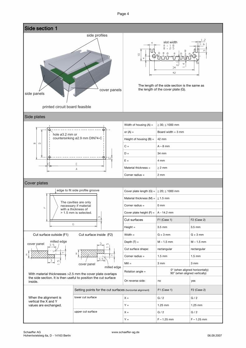
Housing bracketHousing bracketHousing bracketHousing bracket
Description
The housing bracket GZ WI 10 01 can be used, to stabilise housings which are assembled from side or housing profiles. The use ofthis bracket is recommended from a width of 150 mm (for housing profiles this also applies analogously to the height).
Definition by cases
Case 1 Case 2
Side panels Cover panels
Equations
Side profiles Housing profiles
Case 1 Case 2 Case 1 Case 2 A: housing width
WSX= min. 50 mm; max. 100 mm min. 50 mm; max. 100 mm B: housing height
WSX1 .. n= min. 80 mm; max. 100 mm min. 80 mm; max. 100 mm C = A - 2E
WSX' WSX – 4 mm WSX – 5,2 mm D = B - 2E
WSY= 9.3 mm M + 7.7 mm 9,1 mm M + 7.5 mm E(side profile)= 4.0 mm
WSY´= 5.3 mm M + 3.7 mm 3.9 mm M + 2.3 mm E(housing profile)= 5.2 mm
WDX= WSX – 7.1 mm WSX -10,1 mm F: cover panel width
WDX1 .. n= WSX1 .. n WSX1 .. n G: cover panel length
WDY(NT=0)= 6.5 mm 6.5 mm WSY1= B - 2WSY
WDY(NT>0)= NT + 6.4 mm NT + 6.4 mm WDY1= G - 2WDY
Schaeffer AG www.schaeffer-ag.deHohentwielsteig 6a, D - 14163 Berlin 06.09.2007
cover panel
side panel
side orhousing profile
angle(GZ WI 10 01)
coverpanel
side panel
angle
side orhousing profile
coverpanel
side panel
angle
side orhousing profile
hole ø3.2 mm orcountersinking ø3.0 mmDIN74-A
hole ø3.2 mm orcountersinking ø3.0 mmDIN74-A
possible cavity

Page 12
Order numbers for housing brackets
Surface of the brackets natural anodized
Designation Order – No. Remarks
Housing bracket 4 x per unit GG WS 0111
Housing bracket 8 x per unit GG WS 0112
Housing bracket 12 x per unit GG WS 0113
Housing bracket 25 x per unit GG WS 0114
surface drummed
To assemble a housing bracket you will require 2 screws M3 x 5 mm, M3 x 6 mm or M3 x 8 mm.
A packet of screws contains 50 M3 x 5 mm, M3 x 6 mm or M3 x 8 mm screws in acc. with DIN 7985, 965 or 966. The screws aresupplied as either nickel-plated, black or white galvanized.
The M3 x 5 mm screw is suitable for 1.5 mm thick plates.The M3 x 6 mm screw is suitable for 2.0 – 3.0 mm thick plates.The M3 x 8 mm screw is suitable for 4.0 mm thick plates.
Designation Order-No. Screws
Screws white galvanized
Screw packet M3x5-7985-ZI GG RB 1105 Oval head screws in acc. with DIN 7985
Screw packet M3x5-965-ZI GG RB 1305 Countersunk head screws in acc. with DIN 965
Screw packet M3x5-966-ZI GG RB 1405 Oval countersunk head screws in acc. with DIN 966
Screw packet M3x6-7985-ZI GG RB 1106 Oval head screws in acc. with DIN 7985
Screw packet M3x6-965-ZI GG RB 1306 Countersunk head screws in acc. with DIN 965
Screw packet M3x6-966-ZI GG RB 1406 Oval countersunk head screws in acc. with DIN 966
Screw packet M3x8-7985-ZI GG RB 1108 Oval head screws in acc. with DIN 7985
Screw packet M3x8-965-ZI GG RB 1308 Countersunk head screws in acc. with DIN 965
Screw packet M3x8-966-ZI GG RB 1408 Oval countersunk head screws in acc. with DIN 966
Screws nickel-plated
Screw packet M3x5-7985-NI GG RB 2105 Oval head screws in acc. with DIN 7985
Screw packet M3x5-965-NI GG RB 2305 Countersunk head screws in acc. with DIN 965
Screw packet M3x5-966-NI GG RB 2405 Oval countersunk head screws in acc. with DIN 966
Screw packet M3x6-7985-NI GG RB 2106 Oval head screws in acc. with DIN 7985
Screw packet M3x6-965-NI GG RB 2306 Countersunk head screws in acc. with DIN 965
Screw packet M3x6-966-NI GG RB 2406 Oval countersunk head screws in acc. with DIN 966
Screw packet M3x8-7985-NI GG RB 2108 Oval head screws in acc. with DIN 7985
Screw packet M3x8-965-NI GG RB 2308 Countersunk head screws in acc. with DIN 965
Screw packet M3x8-966-NI GG RB 2408 Oval countersunk head screws in acc. with DIN 966
Screws black galvanized
Screw packet M3x5-7985-SW GG RB 3105 Oval head screws in acc. with DIN 7985
Screw packet M3x5-965-SW GG RB 3305 Countersunk head screws in acc. with DIN 965
Screw packet M3x5-966-SW GG RB 3405 Oval countersunk head screws in acc. with DIN 966
Screw packet M3x6-7985-SW GG RB 3106 Oval head screws in acc. with DIN 7985
Screw packet M3x6-965-SW GG RB 3306 Countersunk head screws in acc. with DIN 965
Screw packet M3x6-966-SW GG RB 3406 Oval countersunk head screws in acc. with DIN 966
Screw packet M3x8-7985-SW GG RB 3108 Oval head screws in acc. with DIN 7985
Screw packet M3x8-965-SW GG RB 3308 Countersunk head screws in acc. with DIN 965
Screw packet M3x8-966-SW GG RB 3408 Oval countersunk head screws in acc. with DIN 966
Small screw primer (M 3:1)
DIN 7985 DIN 965 DIN 966
Schaeffer AG www.schaeffer-ag.deHohentwielsteig 6a, D - 14163 Berlin 06.09.2007

Schaeffer AG
Hohentwielsteig 6 a14163 Berlin
Tel +49 (0)30 805 86 95-0Fax +49 (0)30 805 86 95-33