Embed Size (px)
Citation preview
Leergehäuse eCAM
Boîtiers vides eCAM
eCAM empty enclosures
MANUALBVS 15 ATEX E 112 UIECEx BVS 16.0026U
Edition August 2016
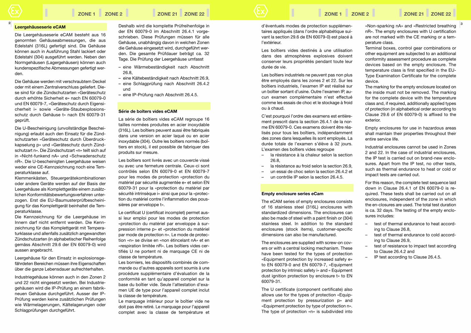
3«Non-sparking nA» and «Restricted breathingnR». The empty enclosures with U certificationare not marked with the CE marking or a tem-perature class. Terminal boxes, control gear combinations orother equipment are subjected to an additionalconformity assessment procedure as completedevices based on the empty enclosure. Thetemperature class is first specified in the EU-Type Examination Certificate for the completedevice. The marking for the empty enclosure located onthe inside must not be removed. The markingfor the complete device with the temperatureclass and, if required, additionally applied typesof protection (in alphabetical order according toClause 29.6 of EN 60079-0) is affixed to theexterior.
Empty enclosures for use in hazardous areasshall maintain their properties throughout theirentire service life.
Industrial enclosures cannot be used in Zones2 and 22. In the case of industrial enclosures,the IP test is carried out on brand-new enclo-sures. Apart from the IP test, no other tests,such as thermal endurance to heat or cold orimpact tests are carried out.
For this reason, the complete test sequence laiddown in Clause 26.4.1 of EN 60079-0 is re -quired. These tests shall be carried out on allenclosures, independent of the zone in whichthe en-closures are used. The total test durationis ca. 32 days. The testing of the empty enclo-sures includes:
– test of thermal endurance to heat accord-ing to Clause 26.8,
– test of thermal endurance to cold accord-ing to Clause 26.9,
– test of resistance to impact test accordingto Clause 26.4.2 and
– IP test according to Clause 26.4.5.
d’éventuels modes de protection supplémen-taires appliqués (dans l’ordre alphabétique sui-vant la section 29.6 de EN 60079-0) est placé àl’extérieur.
Les boîtiers vides destinés à une utilisationdans des atmosphères explosives doiventconserver leurs propriétés pendant toute leurdurée de vie.
Les boîtiers industriels ne peuvent pas non plusêtre employés dans les zones 2 et 22. Sur lesboîtiers industriels, l’examen IP est réalisé surun boîtier sortant d’usine. Outre l’examen IP, au-cun examen complémentaire n’est effectuécomme les essais de choc et le stockage à froidou à chaud.
C’est pourquoi l’ordre des examens est entière-ment prescrit dans la section 26.4.1 de la nor-me EN 60079-0. Ces examens doivent être réa-lisés pour tous les boîtiers, indépendammentdes zones dans lesquelles ils sont employés. Ladurée totale de l’examen s’élève à 32 jours.L’examen des boîtiers vides regroupe– la résistance à la chaleur selon la section
26.8,– la résistance au froid selon la section 26.9,– un essai de choc selon la section 26.4.2 et– un contrôle IP selon la section 26.4.5.
Empty enclosure series eCam
The eCAM series of empty enclosures consistsof 16 stainless steel (316L) enclosures withstandardized dimensions. The enclosures canalso be made of steel with a paint finish or (304)stainless steel. In addition to the standardenclosures (stock items), customer-specificdimensions can also be manufactured.
The enclosures are supplied with screw-on cov-ers or with a central locking mechanism. Thesehave been tested for the types of protection«Equipment protection by increased safety e»to EN 60079-0 and EN 60079-7, «Equipmentprotection by intrinsic safety i» and « Equipmentdust ignition protection by enclosure t» to EN60079-31.
The U certificate (component certificate) alsoallows use for the types of protection «Equip-ment protection by pressurization p» and«Equipment protection by type of protection n».The type of protection «n» is subdivided into
ZONE 1 ZONE 2 ZONE 21 ZONE 22
Leergehäuseserie eCAM
Die Leergehäuseserie eCAM besteht aus 16genormten Gehäuseabmessungen, die ausEdelstahl (316L) gefertigt sind. Die Gehäusekönnen auch in Ausführung Stahl lackiert oderEdelstahl (304) ausgeführt werden. Neben denNormgehäusen (Lagergehäusen) können auchkundenspezifische Abmessungen gefertigt wer-den.
Die Gehäuse werden mit verschraubtem Deckeloder mit einem Zentralverschluss geliefert. Die-se sind für die Zündschutzarten «Geräteschutzdurch erhöhte Sicherheit e» nach EN 60079-0und EN 60079-7, «Geräteschutz durch Eigensi-cherheit i» sowie «Geräte-Staubexplosions-schutz durch Gehäuse t» nach EN 60079-31geprüft.
Die U-Bescheinigung (unvollständige Beschei-nigung) erlaubt auch den Einsatz für die Zünd-schutzarten «Geräteschutz durch Überdruck-kapselung p» und «Geräteschutz durch Zünd-schutzart n». Die Zündschutzart «n» teilt sich aufin «Nicht-funkend nA» und «SchwadenschutznR». Die U-bescheinigten Leergehäuse weisenweder eine CE-Kennzeichnung noch eine Tem-peraturklasse auf.Klemmenkästen, Steuergerätekombinationenoder andere Geräte werden auf der Basis derLeergehäuse als Komplettgeräte einem zusätz-lichen Konformitätsbewertungsverfahren unter-zogen. Erst die EU-Baumusterprüfbescheini-gung für das Komplettgerät beinhaltet die Tem-peraturklasse.Die Kennzeichnung für die Leergehäuse imInnern darf nicht entfernt werden. Die Kenn-zeichnung für das Komplettgerät mit Tempera-turklasse und allenfalls zusätzlich angewandtenZündschutzarten (in alphabetischer Reihenfolgegemäss Abschnitt 29.6 der EN 60079-0) wirdaussen angebracht.
Leergehäuse für den Einsatz in explosionsge-fährdeten Bereichen müssen ihre Eigenschaftenüber die ganze Lebensdauer aufrechterhalten.
Industriegehäuse können auch in den Zonen 2und 22 nicht eingesetzt werden. Bei Industrie-gehäusen wird die IP-Prüfung an einem fabrik-neuen Gehäuse durchgeführt. Ausser der IP-Prüfung werden keine zusätzlichen Prüfungenwie Wärmelagerungen, Kältelagerungen oderSchlagprüfungen durchgeführt.
2Deshalb wird die komplette Prüfreihenfolge inder EN 60079-0 im Abschnitt 26.4.1 vorge-schrieben. Diese Prüfungen müssen für alleGehäuse, unabhängig davon in welchen Zonendie Gehäuse eingesetzt wird, durchgeführt wer-den. Die gesamte Prüfdauer beträgt ca. 32Tage. Die Prüfung der Leergehäuse umfasst
– eine Wärmebeständigkeit nach Abschnitt26.8,
– eine Kältebeständigkeit nach Abschnitt 26.9,– eine Schlagprüfung nach Abschnitt 26.4.2
und– eine IP-Prüfung nach Abschnitt 26.4.5.
Série de boîters vides eCAM
La série de boîtiers vides eCAM regroupe 16tailles normées produites en acier inoxydable(316L). Les boîtiers peuvent aussi être fabriquésdans une version en acier laqué ou en acierinoxydable (304). Outre les boîtiers normés (boî-tiers en stock), il est possible de fabriquer desproduits sur mesure.
Les boîtiers sont livrés avec un couvercle visséou avec une fermeture centrale. Ceux-ci sontcontrôlés selon EN 60079-0 et EN 60079-7pour les modes de protection «protection dumatériel par sécurité augmentée e» et selon EN60079-31 pour la «protection du matériel parsécurité intrinsèque i» ainsi que pour la «protec-tion du matériel contre l’inflammation des pous-sières par enveloppe t».
Le certificat U (certificat incomplet) permet aus-si leur emploi pour les modes de protection«protection du matériel par enveloppe à sur-pression interne p» et «protection du matérielpar mode de protection n». Le mode de protec-tion «n» se divise en «non étincelant nA» et en«respiration limitée nR». Les boîtiers vides cer-tifiés U ne portent ni de marquage CE ni declasse de température.Les borniers, les dispositifs combinés de com-mande ou d’autres appareils sont soumis à uneprocédure supplémentaire d’évaluation de laconformité en tant qu’appareil complet sur labase du boîtier vide. Seule l’attestation d’exa-men UE de type pour l’appareil complet inclutla classe de température.Le marquage intérieur pour le boîtier vide nedoit pas être retiré. Le marquage pour l’appareilcomplet avec la classe de température et
ZONE 1 ZONE 2 ZONE 21 ZONE 22
Manual BVS 15 ATEX E 112 U 3
Edition August 2016 thuba Ltd., CH-4015 BaselCopyright Switzerland
Manual BVS 15 ATEX E 112 U 2
Edition August 2016 thuba Ltd., CH-4015 BaselCopyright Switzerland
Leergehäuse
Typenreihe eCAM
Zelgruppe:Erfahrene Elektrofachkräfte gemäss Betriebssi-cherheitsverordnung und unterwiesene Perso-nen.
Inhalt1. Sicherheitshinweise2. Normenkonformität3. Technische Daten4. Installation5. Entsorgung
1. SicherheitshinweiseDie explosionsgeschützten Leergehäuse mitKomponentenbescheinigung dürfen nur alsBasis für Energieverteilungs-, Schalt- und Steu-ergerätekombination in explosionsgefährdetenBereichen der Zonen 1 und 2 nach EN 60079-10-1 bzw. der Zonen 21 und 22 nach EN 60079-10-2 dienen.
Die Komplettgeräte benötigen eine EU-Bau-
musterprüfbescheinigung einer anerkannten
europäischen Prüfstelle.
Lassen Sie diese Betriebsanleitung und andereGegenstände während des Betriebes nicht indem Gehäuse.
Die Leergehäuse dürfen nur für Anwendungeneingesetzt werden, wo die Beständigkeit desGehäusematerials gewährleistet ist.
Bei nicht korrektem Zusammenbau ist der Min-destschutzgrad IP 66 nach EN 60529 nicht mehrgewährleistet.
Es dürfen keine Veränderungen an den
explosionsgeschützten Leergehäusen eCAM
vorgenommen werden.
Boîtiers vides
Série eCAM
Groupe cible :Électriciens expérimentés selon le décret sur lasécurité au travail et les personnes instruites
Sommaire1. Informations de sécurité2. Conformité aux normes3. Données techniques4. Installation5. Élimination
1. Informations de sécurité
Les boîtiers antidéflagrants avec certification entant que composant ne peuvent servir de baseque pour les dispositifs combinés de distribu-tion d’énergie, de couplage et de commandedans les atmosphères explosives des zones 1et 2 selon CEI 60079-10-1 et des zones 21 et 22selon CEI 60079-10-2.
Les appareils complets nécessitent une atte-
station d’examen UE de type d’un laboratoire
européen reconnu.
Ne laissez ni ces instructions d’utilisation nid’autres objets dans le boîtier pendant leur uti-lisation.
Les boîtiers ne doivent être utilisés que pour desapplications où la résistance du matériau duboîtier est garantie.
Si l’assemblage n’est pas correct, l’indice deprotection minimal IP66 selon CEI 60529 n’estplus garanti.
Aucune modification ne doit être apportée
aux boîtiers antidéflagrants eCAM.
Empty enclosures
Series eCAM (Categories 2G and 2D)
Target group:Experienced qualified electricians in accordancewith the occupational health and safety decreeand trained persons.
Contents:1. Safety rules2. Conformity with standards3. Technical data4. Installation5. Disposal
1. Safety instructions
The explosion-protected empty enclosures withcomponent certification may only be used as abasis for power distribution, switch and controlcombinations in hazardous areas in Zones 1 and2 according to IEC 60079-10-1 and Zones 21and 22 according to IEC 60079-10-2.
The complete distributions require an EU-
Type Examination Certificate from a Europe-
an notified body.
Do not leave this instruction manual or any otherobjects inside the enclosure during operation.
The empty enclosures may only be used forapplications where the stability of the enclosurematerial is ensured.
If assembled incorrectly, the minimum degree ofprotection IP 66 according to IEC 60529 is nolonger ensured.
Modifications to the explosion-protected
empty enclosures of the series eCAM are not
permitted.
2. Conformité aux normes
Les boîtiers antidéflagrants eCAM répondentaux exigences de CEI 60079-0, CEI 60079-7 etCEI 60079-31. Ils ont été conçus, fabriqués etcontrôlés conformément à l’état de la techniqueet selon ISO 9001:2015.
3. Données techniques
3.1 Marquage
II 2G Ex eb IIC Gb II 2D Ex tb IIIC Db
3.2 Attestation d’examen UE de type
BVS 15 ATEX E 112 U
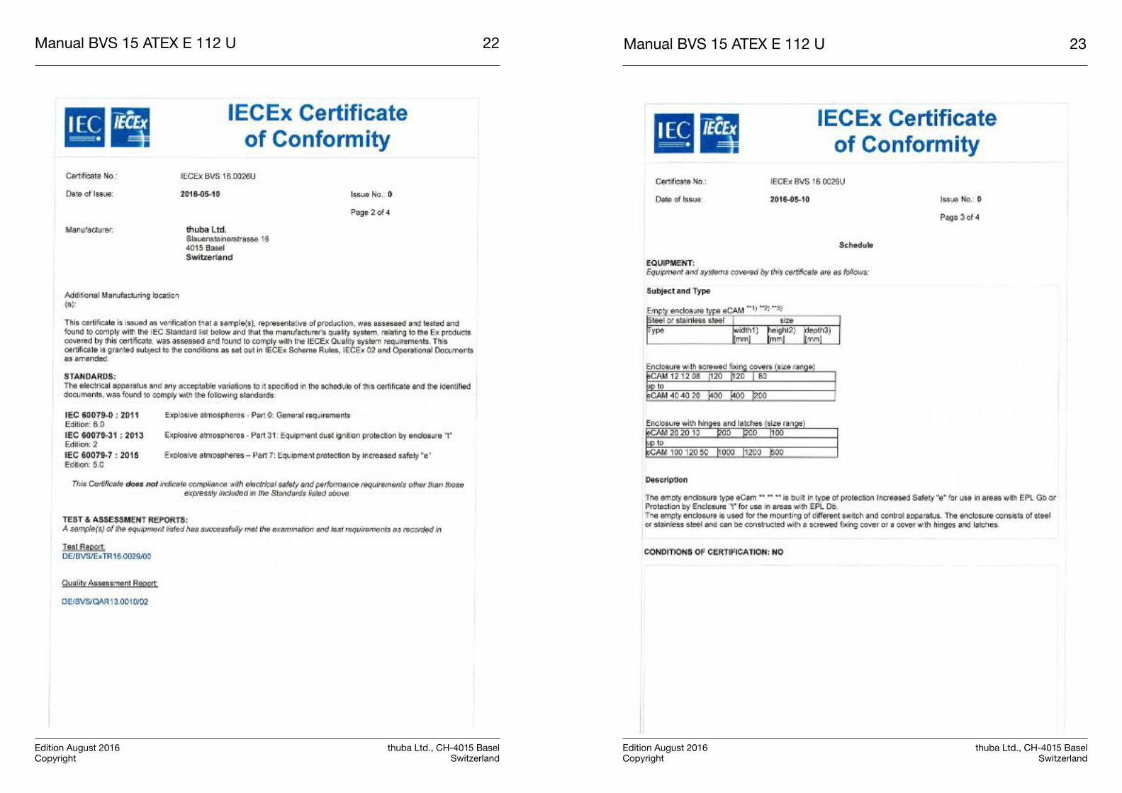
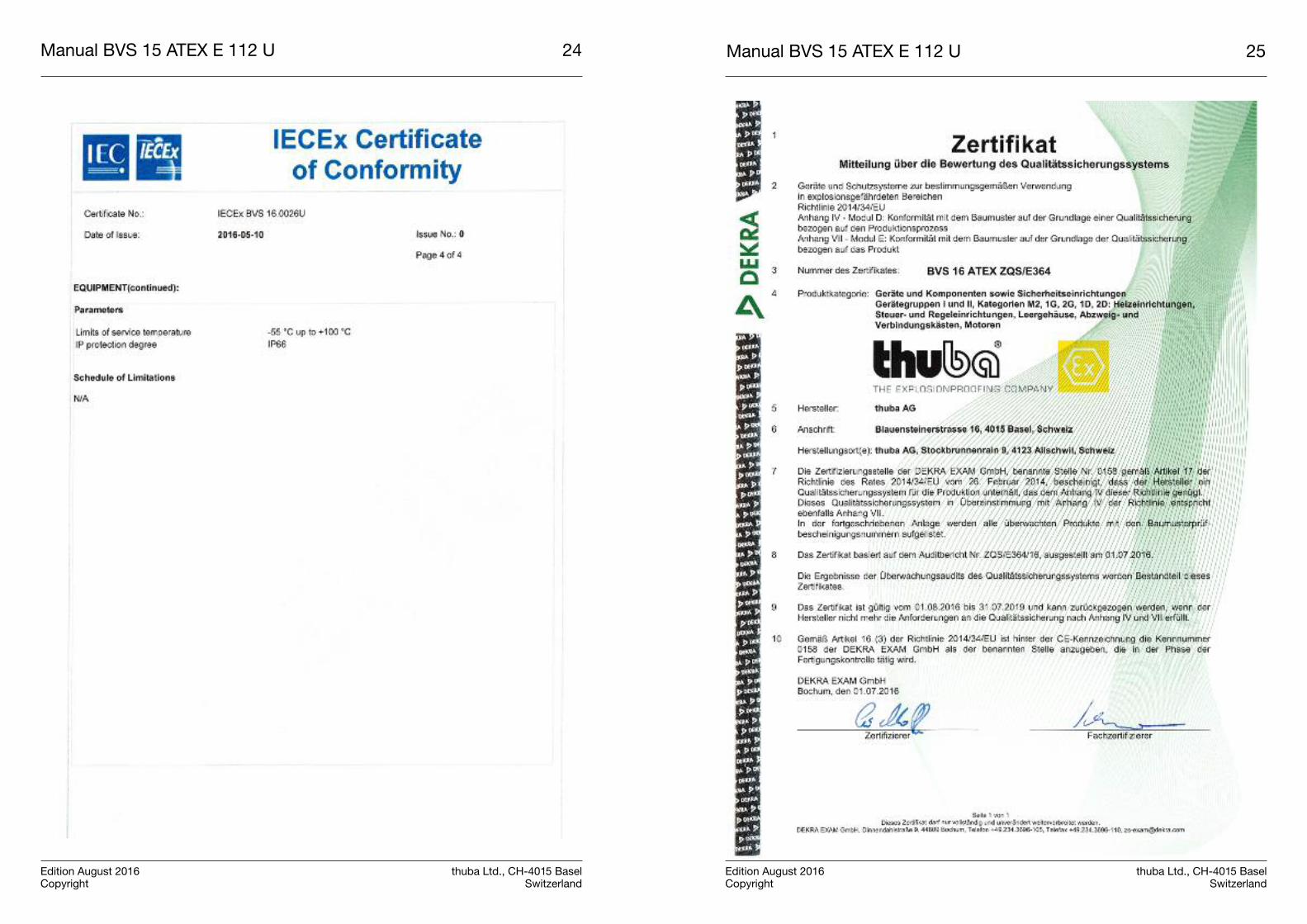
3.3 Certificat de conformité IECEx
IECEx BVS 16.0026U
3.4 Indice de protection du boîtier
Indice de protection minimal IP 661
3.5 Code signalétique général
eCAM Largeur Hauteur Profondeur
Dans le cadre du programme de fabrication, lesdimensions sont fixées en fonction desdemandes du client.
2. Normenkonformität
Die explosionsgeschützten Leergehäuse eCAMentsprechen den Anforderungen der EN 60079-0, EN 60079-7 und EN 60079-31. Sie wurdenentsprechend dem Stand der Technik undgemäss der ISO 9001:2015 entwickelt, gefertigtund geprüft.
3. Technische Daten
3.1 Kennzeichnung
II 2G Ex eb IIC Gb II 2D Ex tb IIIC Db
3.2 EU-Baumusterprüfbescheinigung
BVS 15 ATEX E 112 U
3.3 IECEx Certificate of Conformity
IECEx BVS 16.0026U
3.4 Gehäuseschutzgrad
Mindestschutzart IP 661
3.5 Allgemeiner Typenschlüssel
eCAM Breite Höhe Tiefe
Im Rahmen des Fertigungsprogramms werdendie Abmessungen kundenspezifisch festgelegt.
2. Conformity to standards
The explosion-protected empty enclosures ofthe series eCam meet the requirements of IEC60079-0, IEC 60079-7 and IEC 60079-31. Theyhave been developed, manufactured and testedin accordance with state-of-the-art engineeringpractice and ISO9001:2015.
3. Technical data
3.1 Marking
II 2G Ex eb IIC Gb II 2D Ex tb IIIC Db
3.2 EU-Type Examination Certificate
BVS 15 ATEX E 112 U
3.3 IECEx Certificate of Conformity
IECEx BVS 16.0026U
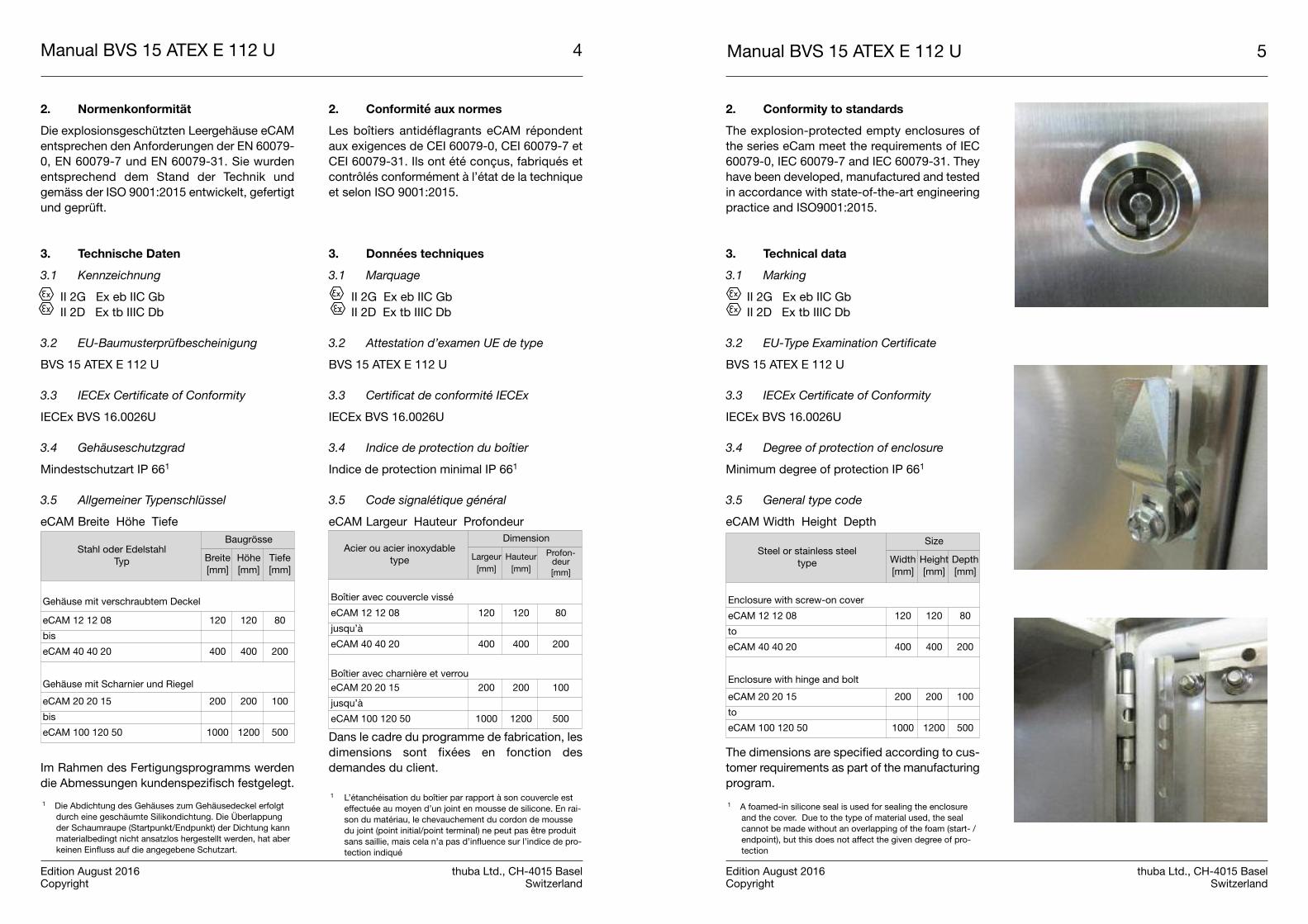
3.4 Degree of protection of enclosure
Minimum degree of protection IP 661
3.5 General type code
eCAM Width Height Depth
The dimensions are specified according to cus-tomer requirements as part of the manufacturingprogram.
Manual BVS 15 ATEX E 112 U 5
Edition August 2016 thuba Ltd., CH-4015 BaselCopyright Switzerland
Manual BVS 15 ATEX E 112 U 4
Edition August 2016 thuba Ltd., CH-4015 BaselCopyright Switzerland
1 Die Abdichtung des Gehäuses zum Gehäusedeckel erfolgtdurch eine geschäumte Silikondichtung. Die Überlappungder Schaumraupe (Startpunkt/Endpunkt) der Dichtung kannmaterialbedingt nicht ansatzlos hergestellt werden, hat aberkeinen Einfluss auf die angegebene Schutzart.
1 A foamed-in silicone seal is used for sealing the enclosureand the cover. Due to the type of material used, the sealcannot be made without an overlapping of the foam (start- /endpoint), but this does not affect the given degree of pro-tection
1 L’étanchéisation du boîtier par rapport à son couvercle esteffectuée au moyen d’un joint en mousse de silicone. En rai-son du matériau, le chevauchement du cordon de moussedu joint (point initial/point terminal) ne peut pas être produitsans saillie, mais cela n’a pas d’influence sur l’indice de pro-tection indiqué
Stahl oder EdelstahlTyp
Baugrösse
Breite[mm]
Höhe[mm]
Tiefe[mm]
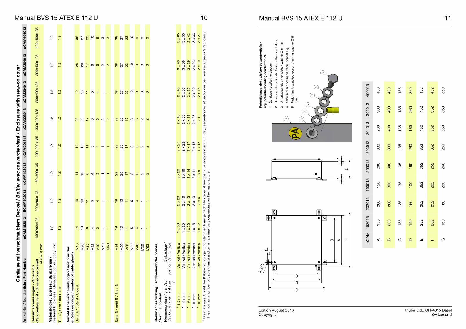
Gehäuse mit verschraubtem Deckel
eCAM 12 12 08 120 120 80
bis
eCAM 40 40 20 400 400 200
Gehäuse mit Scharnier und Riegel
eCAM 20 20 15 200 200 100
bis
eCAM 100 120 50 1000 1200 500
Steel or stainless steeltype
Size
Width[mm]
Height[mm]
Depth[mm]
Enclosure with screw-on cover
eCAM 12 12 08 120 120 80
to
eCAM 40 40 20 400 400 200
Enclosure with hinge and bolt
eCAM 20 20 15 200 200 100
to
eCAM 100 120 50 1000 1200 500
Acier ou acier inoxydabletype
Dimension
Largeur[mm]
Hauteur[mm]
Profon-deur[mm]
Boîtier avec couvercle vissé
eCAM 12 12 08 120 120 80
jusqu’à
eCAM 40 40 20 400 400 200
Boîtier avec charnière et verroueCAM 20 20 15 200 200 100
jusqu’à
eCAM 100 120 50 1000 1200 500
3.6 Drehmomente
3.6.1 Deckelschrauben
Drehmoment 0,8 Nm
3.6.2 Flanschen
Drehmoment 0,4 Nm
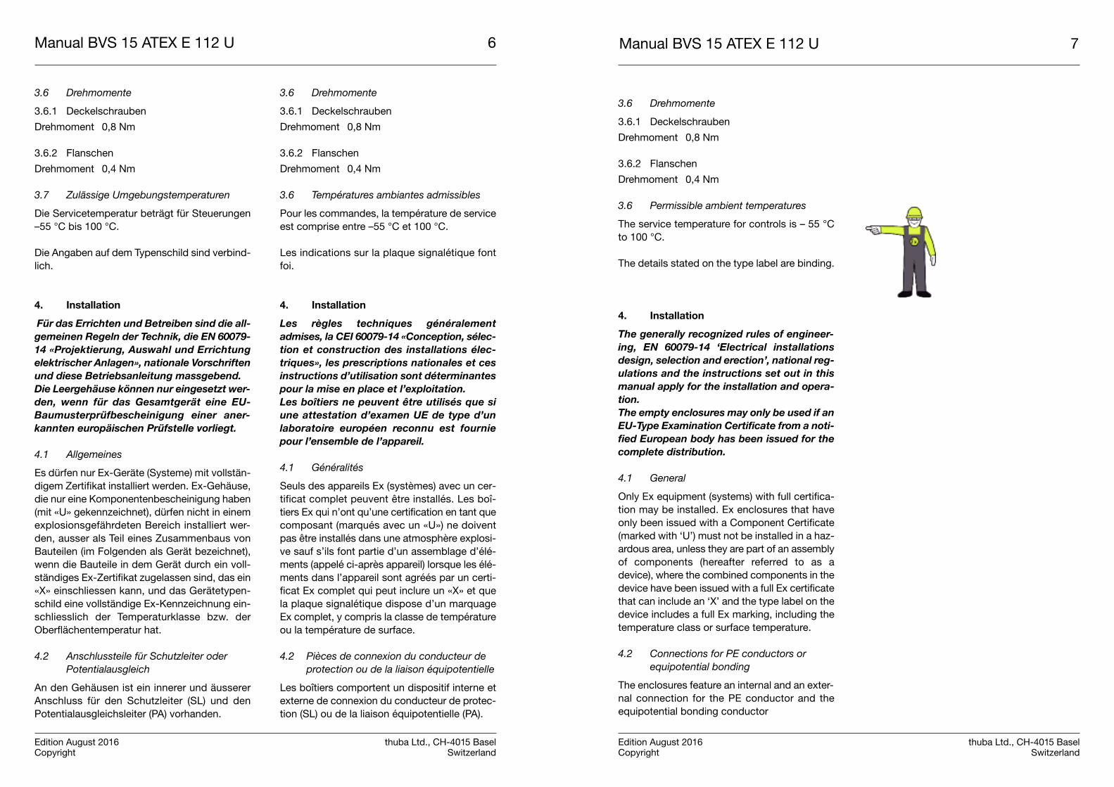
3.6 Permissible ambient temperatures
The service temperature for controls is – 55 °Cto 100 °C.
The details stated on the type label are binding.
4. Installation
The generally recognized rules of engineer-
ing, EN 60079-14 ‘Electrical installations
design, selection and erection’, national reg-
ulations and the instructions set out in this
manual apply for the installation and opera-
tion.
The empty enclosures may only be used if an
EU-Type Examination Certificate from a noti-
fied European body has been issued for the
complete distribution.
4.1 General
Only Ex equipment (systems) with full certifica-tion may be installed. Ex enclosures that haveonly been issued with a Component Certificate(marked with ‘U’) must not be installed in a haz-ardous area, unless they are part of an assemblyof components (hereafter referred to as adevice), where the combined components in thedevice have been issued with a full Ex certificatethat can include an ‘X’ and the type label on thedevice includes a full Ex marking, including thetemperature class or surface temperature.
4.2 Connections for PE conductors or
equipotential bonding
The enclosures feature an internal and an exter-nal connection for the PE conductor and theequipotential bonding conductor
Manual BVS 15 ATEX E 112 U 7
Edition August 2016 thuba Ltd., CH-4015 BaselCopyright Switzerland
Manual BVS 15 ATEX E 112 U 6
Edition August 2016 thuba Ltd., CH-4015 BaselCopyright Switzerland
3.6 Drehmomente
3.6.1 Deckelschrauben
Drehmoment 0,8 Nm
3.6.2 Flanschen
Drehmoment 0,4 Nm
3.7 Zulässige Umgebungstemperaturen
Die Servicetemperatur beträgt für Steuerungen–55 °C bis 100 °C.
Die Angaben auf dem Typenschild sind verbind-lich.
4. Installation
Für das Errichten und Betreiben sind die all-
gemeinen Regeln der Technik, die EN 60079-
14 «Projektierung, Auswahl und Errichtung
elektrischer Anlagen», nationale Vorschriften
und diese Betriebsanleitung massgebend.
Die Leergehäuse können nur eingesetzt wer-
den, wenn für das Gesamtgerät eine EU-
Baumusterprüfbescheinigung einer aner-
kannten europäischen Prüfstelle vorliegt.
4.1 Allgemeines
Es dürfen nur Ex-Geräte (Systeme) mit vollstän-digem Zertifikat installiert werden. Ex-Gehäuse,die nur eine Komponentenbescheinigung haben(mit «U» gekennzeichnet), dürfen nicht in einemexplosionsgefährdeten Bereich installiert wer-den, ausser als Teil eines Zusammenbaus vonBauteilen (im Folgenden als Gerät bezeichnet),wenn die Bauteile in dem Gerät durch ein voll-ständiges Ex-Zertifikat zugelassen sind, das ein«X» einschliessen kann, und das Gerätetypen-schild eine vollständige Ex-Kennzeichnung ein-schliesslich der Temperaturklasse bzw. derOberflächentemperatur hat.
4.2 Anschlussteile für Schutzleiter oder
Potentialausgleich
An den Gehäusen ist ein innerer und äussererAnschluss für den Schutzleiter (SL) und denPotentialausgleichsleiter (PA) vorhanden.
3.6 Drehmomente
3.6.1 Deckelschrauben
Drehmoment 0,8 Nm
3.6.2 Flanschen
Drehmoment 0,4 Nm
3.6 Températures ambiantes admissibles
Pour les commandes, la température de serviceest comprise entre –55 °C et 100 °C.
Les indications sur la plaque signalétique fontfoi.
4. Installation
Les règles techniques généralement
admises, la CEI 60079-14 «Conception, sélec-
tion et construction des installations élec-
triques», les prescriptions nationales et ces
instructions d’utilisation sont déterminantes
pour la mise en place et l’exploitation.
Les boîtiers ne peuvent être utilisés que si
une attestation d’examen UE de type d’un
laboratoire européen reconnu est fournie
pour l’ensemble de l’appareil.
4.1 Généralités
Seuls des appareils Ex (systèmes) avec un cer-tificat complet peuvent être installés. Les boî-tiers Ex qui n’ont qu’une certification en tant quecomposant (marqués avec un «U») ne doiventpas être installés dans une atmosphère explosi-ve sauf s’ils font partie d’un assemblage d’élé-ments (appelé ci-après appareil) lorsque les élé-ments dans l’appareil sont agréés par un certi-ficat Ex complet qui peut inclure un «X» et quela plaque signalétique dispose d’un marquageEx complet, y compris la classe de températureou la température de surface.
4.2 Pièces de connexion du conducteur de
protection ou de la liaison équipotentielle
Les boîtiers comportent un dispositif interne etexterne de connexion du conducteur de protec-tion (SL) ou de la liaison équipotentielle (PA).
Manual BVS 15 ATEX E 112 U 9
Edition August 2016 thuba Ltd., CH-4015 BaselCopyright Switzerland
Manual BVS 15 ATEX E 112 U 8
Edition August 2016 thuba Ltd., CH-4015 BaselCopyright Switzerland
Tabelle 1: Mindestquerschnitt der Schutzleiterklemm-stelle
4.2.1 Schutzleiteranschluss innen
Im Einzelnen erfolgt der Anschluss des Schutz-leiters innen mit den mitgelieferten Muttern,Unterlagscheiben und Federringen.
4.2.1 Anschluss des Schutzpotentialaus-gleichs aussen
In der Gehäusewand ist eine Gewindehülsen M6eingeschweisst. Der Schutzpotentialleiter miteinem Mindestquerschnitt von 4 mm² wird miteinem handelsüblichen Kabelschuh passendenQuerschnitts und Ringdurchmessers ange-schlossen. Die gewählten Kabelschuhe solltender Norm DIN 46234 für Ringkabelschuhe ent-sprechen. Diese Forderung gilt für massive Ein-zelleiter wie auch für mehradrige Leiter.
4.3 Einführungsöffnungen und Durchgangs-
bohrungen bei Einsätzen in staubexplo-
sionsgefährdeten Bereichen
Einsatz von Kabel- und Leitungseinführungen inDurchgangsbohrungen:– Kunststoffverschraubungen der Kategorie
2D mit Gegenmutter– Metallverschraubung mit zusätzlicher Dich-
tung der Kategorie 2D und Gegenmutter(vorzugsweise Kabel- und Leitungsein-führungen mit O-Ring).
5. Entsorgung
Bei der Entsorgung der Leergehäuse eCAM sinddie jeweiligen geltenden nationalen Abfallbesei-tigungsvorschriften zu beachten.
Tableau 1: section min. admise des points de serragedes conducteurs
4.2.1 Connexion interne du conducteur deprotection
La connexion du conducteur de protection esteffectuée en particulier avec les écrous, les ron-delles et les rondelles ressort fournis.
4.2.2 Connexion externe du conducteurd’équipotentialité de protection
Une douille filetée M6 est soudée dans la paroidu boîtier. Le conducteur du potentiel de pro-tection avec une section minimale de 4 mm² estraccordé avec une cosse de câble du commer-ce avec section et diamètre de bague adéquats.Les cosses choisies doivent répondre à la nor-me DIN 46234 pour les cosses à œillets. Cetteexigence s’applique aussi bien aux conducteursindividuels massifs qu’aux conducteurs multi-brins.
4.3 Ouvertures d’insertion et perçages tra-
versants dans le cas des utilisations en
atmosphères poussiéreuses explosives
Recours à des entrées de câble et de conduc-teur dans des perçages traversants:– Presse-étoupe en plastique de catégorie
2D avec contre-écrou– Presse-étoupe en métal avec joint supplé-
mentaire de catégorie 2D et contre-écrou(de préférence entrées de câble et deconducteur avec joint torique)
5. Élimination
Il faut respecter les prescriptions nationales res-pectives en matière d’élimination des déchetslors de la mise au rebut du boîtier eCAM.
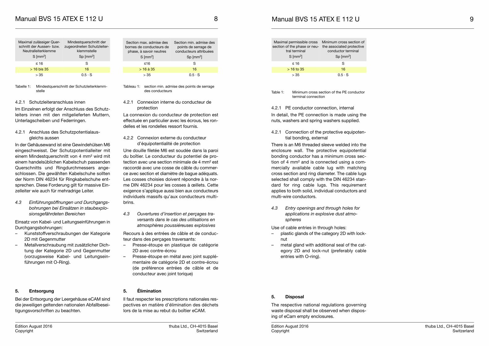
Table 1: Minimum cross section of the PE conductorterminal connection
4.2.1 PE conductor connection, internal
In detail, the PE connection is made using thenuts, washers and spring washers supplied.
4.2.1 Connection of the protective equipoten-tial bonding, external
There is an M6 threaded sleeve welded into theenclosure wall. The protective equipotentialbonding conductor has a minimum cross sec-tion of 4 mm² and is connected using a com-mercially available cable lug with matchingcross section and ring diameter. The cable lugsselected shall comply with the DIN 46234 stan-dard for ring cable lugs. This requirementapplies to both solid, individual conductors andmulti-wire conductors.
4.3 Entry openings and through holes for
applications in explosive dust atmo -
spheres
Use of cable entries in through holes: – plastic glands of the category 2D with lock-
nut – metal gland with additional seal of the cat-
egory 2D and lock-nut (preferably cableentries with O-ring).
5. Disposal
The respective national regulations governingwaste disposal shall be observed when dispos-ing of eCam empty enclosures.
Section max. admise desbornes de conducteurs de
phase, à savoir neutres
S [mm2]
Section min. admise despoints de serrage de
conducteurs attribuées
Sp [mm2]
≤16 S
> 16 à 35 16
> 35 0.5 · S
Maximal permissible crosssection of the phase or neu-
tral terminal
S [mm2]
Minimum cross section ofthe associated protective
conductor terminal
Sp [mm2]
≤ 16 S
> 16 to 35 16
> 35 0.5 · S
Maximal zulässiger Quer-schnitt der Aussen- bzw.
Neutralleiterklemme
S [mm2]
Mindestquerschnitt derzugeordneten Schutzleiter-
klemmstelle
Sp [mm2]
≤ 16 S
> 16 bis 35 16
> 35 0.5 · S
Manual BVS 15 ATEX E 112 U 10 Manual BVS 15 ATEX E 112 U 11
Edition August 2016 thuba Ltd., CH-4015 BaselCopyright Switzerland
eCA
M15
2013
2020
1315
3013
2030
1330
3013
2040
1330
4013
4040
13
A15
020
015
020
030
020
030
040
0
B20
020
030
030
030
040
040
040
0
C13
513
513
513
513
513
513
513
5
D19
016
010
016
026
016
026
036
0
E25
225
235
235
235
245
245
245
2
F20
225
220
225
235
225
235
245
2
G16
016
026
026
026
036
036
036
0
A
B
C
13.5
13
G
E
17
94x
D F
23
4
5
6
1
3
Po
ten
tial
ausg
leic
h/
Lia
iso
n é
qu
ipo
ten
tie
lle
/ eq
uip
ote
nti
al b
on
din
g c
on
du
cto
r P
A
1
Geh
äuse
/ b
oîtie
r /
encl
osur
e
2
Gew
ind
ehül
se /
do
uill
e f
ileté
e /
thr
ead
ed s
leev
e
3
Unt
erla
gsch
eib
e /
rond
elle
/ w
ashe
r Ø
6 m
m
4
Kab
elsc
huh
/ co
sse d
e c
âb
le/
cab
el lu
g
5
Fed
errin
g /
rond
elle
s r
esso
rt/
sprin
g w
ashe
r Ø
6m
m
Geh
äuse
mit
ver
sch
rau
bte
m D
ecke
l / B
oît
ier
ave
c c
ou
ve
rcle
vis
sé
/ E
ncl
osu
re w
ith
sre
w-o
n c
ove
rA
rtik
el-N
r. /
No
. d’a
rtic
le /
Par
t N
um
ber
eCA
M15
2013
EC
AM
2020
13eC
AM
1530
13eC
AM
2013
13eC
AM
3030
13eC
AM
2040
13eC
AM
3040
13eC
AM
4040
13
Ges
amta
bm
essu
ng
en /
dim
en
sio
n
d’e
nco
mb
rem
en
t/
dim
ensi
on
s o
vera
ll (A
xBxC
)m
m15
0x20
0x13
520
0x20
0x13
515
0x30
0x13
520
0x30
0x13
530
0x30
0x13
520
0x40
0x13
530
0x40
0x13
540
0x40
0x13
5
Mat
eria
ldic
ke /
ép
ais
se
ur
du
ma
téri
au
/ m
ater
ial t
hic
knes
s, G
ehäu
se /
boî
tier
/ b
ody
mm
1.2
1.2
1.2
1.2
1.2
1.2
1.2
1.2
Türe
/ p
ort
e/
doo
r m
m1.
21.
21.
21.
21.
21.
21.
21.
2
An
zah
l Kab
elve
rsch
rau
bu
ng
en /
no
mb
res d
es
en
tré
es d
e c
âb
le/
nu
mb
er o
f ca
ble
gla
nd
sS
eite
A /
cô
té A
/ S
ide
A
M16
1419
1419
2819
2838
M20
1013
1013
2013
2027
M25
811
811
1711
1723
M32
45
45
85
810
M40
34
34
64
69
M50
11
11
21
23
M63
11
11
21
23
Sei
te B
/ c
ôté
B/
Sid
e B
M
1619
1928
2828
3838
38
M20
1313
2020
2027
2727
M25
1111
1717
1723
2323
M
325
58
88
1010
10
M40
44
66
69
99
M
501
12
22
33
3
M
631
12
22
33
3
Kle
mm
enb
estü
cku
ng
/ e
qu
ipe
me
nt
de
s b
orn
es
/ te
rmin
al c
on
ten
t
Kle
mm
engr
össe
/ g
rand
eur
Ein
bau
lage
/d
es b
orn
es
/ te
rmin
al s
ize
po
sitio
nd
e m
onta
ge
/
*2.
5 m
mVe
rtik
al /
Ver
tical
1 x
302
x 20
2 x
232
x 27
2 x
462
x 40
3 x
463
x 65
*4
mm
Vert
ikal
/ V
ertic
al1
x 25
2 x
162
x 19
2 x
222
x 38
2 x
333
x 38
3 x
55
*6
mm
Vert
ikal
/ V
ertic
al1
x 20
2 x
132
x 14
2 x
172
x 29
2 x
253
x 29
3 x
42
*10
mm
Vert
ikal
/ V
ertic
al1
x 15
2 x
102
x 11
2 x
132
x 23
2 x
202
x 23
3 x
33
*16
mm
Vert
ikal
/ V
ertic
al1
x 12
2 x
82
x 9
1 x
151
x 19
2 x
162
x 19
3 x
27
*Die
max
imal
e A
nzah
l der
Kab
elei
nfüh
rung
en u
nd K
lem
men
kan
n je
nac
h H
erst
elle
r ab
wei
chen
/ L
e n
om
bre
maxim
um
de p
resse-é
tou
pes e
t d
e b
orn
es p
eu
ven
t vairer
selo
n le f
ab
rican
t/
The
max
imum
num
ber
of c
able
gla
nds
and
ter
min
als
may
var
y d
epen
din
g on
the
man
ufac
ture
r
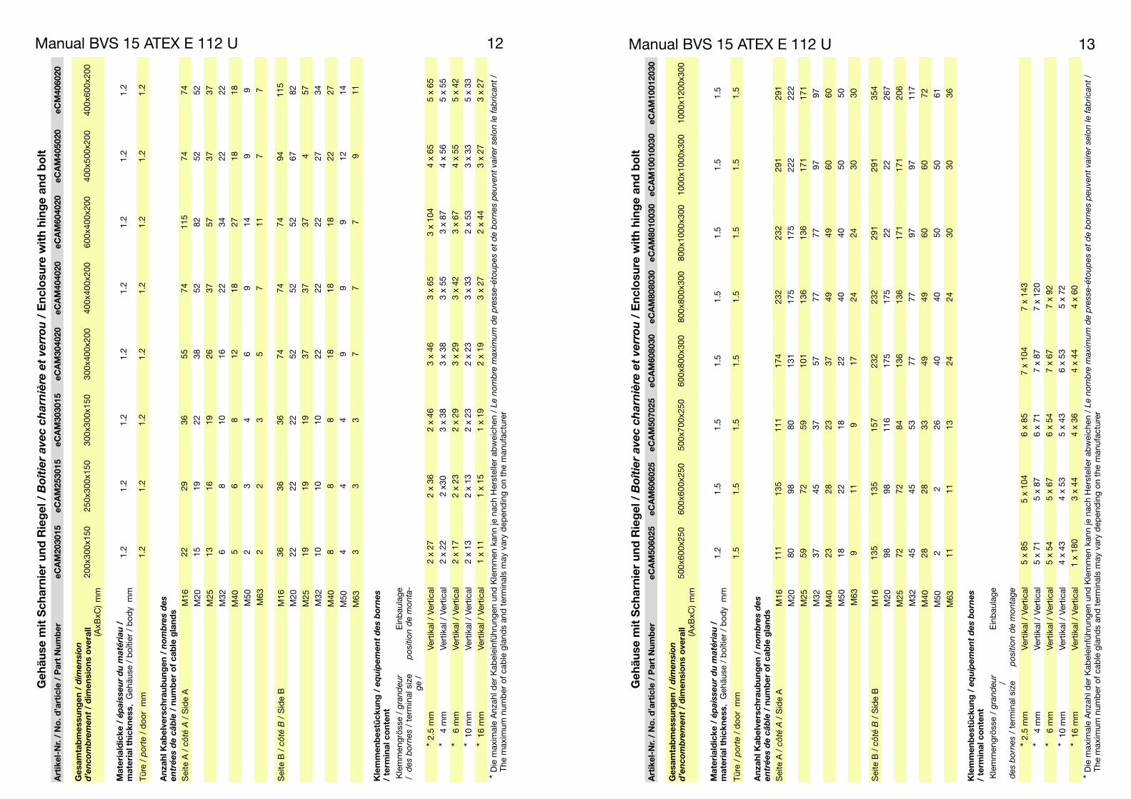
Manual BVS 15 ATEX E 112 U 13Manual BVS 15 ATEX E 112 U 12G
ehäu
se m
it S
char
nie
r u
nd
Rie
gel
/ B
oît
ier
ave
c c
ha
rniè
re e
t ve
rro
u/
En
clo
sure
wit
h h
ing
e an
d b
olt
Art
ikel
-Nr.
/ N
o. d
’art
icle
/ P
art
Nu
mb
ereC
AM
2030
15eC
AM
2530
15eC
AM
3030
15eC
AM
3040
20eC
AM
4040
20eC
AM
6040
20eC
AM
4050
20eC
M40
6020
Ges
amta
bm
essu
ng
en /
dim
en
sio
n
d’e
nco
mb
rem
en
t/
dim
ensi
on
s o
vera
ll (AxB
xC)
mm
200x
300x
150
250x
300x
150
300x
300x
150
300x
400x
200
400x
400x
200
600x
400x
200
400x
500x
200
400x
600x
200
Mat
eria
ldic
ke /
ép
ais
se
ur
du
ma
téri
au
/ m
ater
ial t
hic
knes
s, G
ehäu
se /
boî
tier
/ b
ody
mm
1.2
1.2
1.2
1.2
1.2
1.2
1.2
1.2
Türe
/ p
ort
e/
doo
r m
m1.
21.
21.
21.
21.
21.
21.
21.
2
An
zah
l Kab
elve
rsch
rau
bu
ng
en /
no
mb
res d
es
en
tré
es d
e c
âb
le/
nu
mb
er o
f ca
ble
gla
nd
sS
eite
A /
cô
té A
/ S
ide
A
M16
2229
3655
7411
574
74
M20
1519
2238
5282
5252
M25
1316
1926
3757
3737
M32
68
1016
2234
2222
M40
56
812
1827
1818
M50
23
46
914
99
M63
22
35
711
77
Sei
te B
/ c
ôté
B/
Sid
e B
M
1636
3636
7474
7494
115
M20
2222
2252
5252
6782
M25
1919
1937
3737
457
M
3210
1010
2222
2227
34
M40
88
818
1818
2227
M
504
44
99
912
14
M
633
33
77
79
11
Kle
mm
enb
estü
cku
ng
/ e
qu
ipe
me
nt
de
s b
orn
es
/ te
rmin
al c
on
ten
t
Kle
mm
engr
össe
/ g
rand
eur
Ein
bau
lage
/ d
es b
orn
es
/ te
rmin
al s
ize
po
sitio
nd
e m
onta
-g
e/
*2.
5 m
mVe
rtik
al /
Ver
tical
2 x
272
x 36
2 x
463
x 46
3 x
653
x 10
44
x 65
5 x
65
*4
mm
Vert
ikal
/ V
ertic
al2
x 22
2 x3
03
x 38
3 x
383
x 55
3 x
874
x 56
5 x
55
*6
mm
Vert
ikal
/ V
ertic
al2
x 17
2 x
232
x 29
3 x
293
x 42
3 x
674
x 55
5 x
42
*10
mm
Vert
ikal
/ V
ertic
al2
x 13
2 x
132
x 23
2 x
233
x 33
2 x
533
x 33
5 x
33
*16
mm
Vert
ikal
/ V
ertic
al1
x 11
1 x
151
x 19
2 x
193
x 27
2 x
443
x 27
3 x
27
*Die
max
imal
e A
nzah
l der
Kab
elei
nfüh
rung
en u
nd K
lem
men
kan
n je
nac
h H
erst
elle
r ab
wei
chen
/ L
e n
om
bre
maxim
um
de p
resse-é
tou
pes e
t d
e b
orn
es p
eu
ven
t vairer
selo
n le f
ab
rican
t/
The
max
imum
num
ber
of c
able
gla
nds
and
ter
min
als
may
var
y d
epen
din
g on
the
man
ufac
ture
r
Geh
äuse
mit
Sch
arn
ier
un
d R
ieg
el /
Bo
îtie
r a
ve
c c
ha
rniè
re e
t ve
rro
u/
En
clo
sure
wit
h h
ing
e an
d b
olt
Art
ikel
-Nr.
/ N
o. d
’art
icle
/ P
art
Nu
mb
ereC
AM
5060
25eC
AM
6060
25eC
AM
5070
25eC
AM
6080
30eC
AM
8080
30eC
AM
8010
030
eCA
M10
0100
30eC
AM
1001
2030
Ges
amta
bm
essu
ng
en /
dim
en
sio
n
d’e
nco
mb
rem
en
t/
dim
ensi
on
s o
vera
ll (AxB
xC)
mm
500x
600x
250
600x
600x
250
500x
700x
250
600x
800x
300
800x
800x
300
800x
1000
x300
1000
x100
0x30
010
00x1
200x
300
Mat
eria
ldic
ke /
ép
ais
se
ur
du
ma
téri
au
/ m
ater
ial t
hic
knes
s, G
ehäu
se /
boî
tier
/ b
ody
mm
1.2
1.5
1.5
1.5
1.5
1.5
1.5
1.5
Türe
/ p
ort
e/
doo
r m
m1.
51.
51.
51.
51.
51.
51.
51.
5
An
zah
l Kab
elve
rsch
rau
bu
ng
en /
no
mb
res d
es
en
tré
es d
e c
âb
le/
nu
mb
er o
f ca
ble
gla
nd
sS
eite
A /
cô
té A
/ S
ide
A
M16
111
135
111
174
232
232
291
291
M20
8098
8013
117
517
522
222
2
M25
5972
5910
113
613
617
117
1
M32
3745
3757
7777
9797
M40
2328
2337
4949
6060
M50
1822
1822
4040
5050
M63
911
917
2424
3030
Sei
te B
/ c
ôté
B/
Sid
e B
M
1613
513
515
723
223
229
129
135
4
M20
9898
116
175
175
2222
267
M25
7272
8413
613
617
117
120
6
M
3245
4553
7777
9797
117
M40
2828
3349
4960
6072
M
502
226
4040
5050
61
M
6311
1113
2424
3030
36
Kle
mm
enb
estü
cku
ng
/ e
qu
ipe
me
nt
de
s b
orn
es
/ te
rmin
al c
on
ten
tK
lem
men
grös
se /
gra
nd
eur
Ein
bau
lage
/
des b
orn
es
/ te
rmin
al s
ize
po
sitio
nd
e m
onta
ge
*2.
5 m
mVe
rtik
al /
Ver
tical
5 x
855
x 10
46
x 85
7 x
104
7 x
143
*4
mm
Vert
ikal
/ V
ertic
al5
x 71
5 x
876
x 71
7 x
877
x 12
0
*6
mm
Vert
ikal
/ V
ertic
al5
x 54
5 x
676
x 54
7 x
677
x 92
*10
mm
Vert
ikal
/ V
ertic
al4
x 43
4 x
535
x 43
6 x
535
x 72
*16
mm
Vert
ikal
/ V
ertic
al1
x 18
03
x 44
4 x
364
x 44
4 x
60
*Die
max
imal
e A
nzah
l der
Kab
elei
nfüh
rung
en u
nd K
lem
men
kan
n je
nac
h H
erst
elle
r ab
wei
chen
/ L
e n
om
bre
maxim
um
de p
resse-é
tou
pes e
t d
e b
orn
es p
eu
ven
t vairer
selo
n le f
ab
rican
t/
The
max
imum
num
ber
of c
able
gla
nds
and
ter
min
als
may
var
y d
epen
din
g on
the
man
ufac
ture
r
Manual BVS 15 ATEX E 112 U 14
Edition August 2016 thuba Ltd., CH-4015 BaselCopyright Switzerland
Manual BVS 15 ATEX E 112 U 15
Edition August 2016 thuba Ltd., CH-4015 BaselCopyright Switzerland
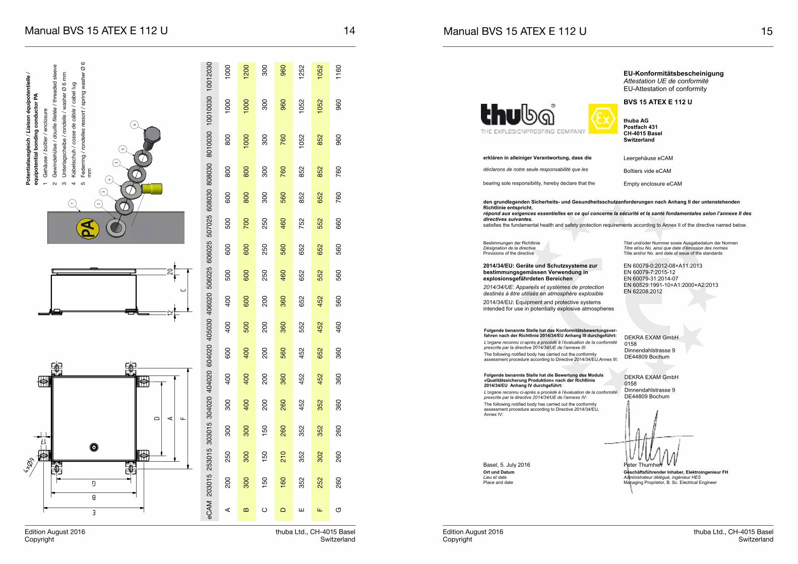
EU-Konformitätsbescheinigung Attestation UE de conformité EU-Attestation of conformity BVS 15 ATEX E 112 U
Wir / Nous / We, thuba AG Postfach 431 CH-4015 Basel Switzerland
erklären in alleiniger Verantwortung, dass die déclarons de notre seule responsabilité que les bearing sole responsibility, hereby declare that the
Leergehäuse eCAM Boîtiers vide eCAM Empty enclosure eCAM
den grundlegenden Sicherheits- und Gesundheitsschutzanforderungen nach Anhang II der untenstehenden Richtlinie entspricht. répond aux exigences essentielles en ce qui concerne la sécurité et la santé fondamentales selon l’annexe II des directives suivantes. satisfies the fundamental health and safety protection requirements according to Annex II of the directive named below. Bestimmungen der Richtlinie Désignation de la directive Provisions of the directive
Titel und/oder Nummer sowie Ausgabedatum der Normen Titre et/ou No. ainsi que date d’émission des normes Title and/or No. and date of issue of the standards
2014/34/EU: Geräte und Schutzsysteme zur bestimmungsgemässen Verwendung in explosionsgefährdeten Bereichen 2014/34/UE: Appareils et systèmes de protection destinés à être utilisés en atmosphère explosible 2014/34/EU: Equipment and protective systems intended for use in potentially explosive atmospheres
EN 60079-0:2012-08+A11:2013 EN 60079-7:2015-12 EN 60079-31:2014-07 EN 60529:1991-10+A1:2000+A2:2013 EN 62208:2012
Folgende benannte Stelle hat das Konformitätsbewertungsver-fahren nach der Richtlinie 2014/34/EU Anhang III durchgeführt: L’organe reconnu ci-après a procédé à l’évaluation de la conformité prescrite par la directive 2014/34/UE de l’annexe III: The following notified body has carried out the conformity assessment procedure according to Directive 2014/34/EU,Annex III:
DEKRA EXAM GmbH 0158 Dinnendahlstrasse 9 DE44809 Bochum
Folgende benannte Stelle hat die Bewertung des Moduls «Qualitätssicherung Produktion» nach der Richtlinie 2014/34/EU Anhang IV durchgeführt: L’organe reconnu ci-après a procédé à l’évaluation de la conformité prescrite par la directive 2014/34/UE de l’annexe IV: The following notified body has carried out the conformity assessment procedure according to Directive 2014/34/EU, Annex IV:
DEKRA EXAM GmbH 0158 Dinnendahlstrasse 9 DE44809 Bochum
Basel, 5. July 2016 Peter Thurnherr Ort und Datum Lieu et date Place and date
Geschäftsführender Inhaber, Elektroingenieur FH Administrateur délégué, ingénieur HES Managing Proprietor, B. Sc. Electrical Engineer
eCA
M20
3015
2530
1530
3015
3040
2040
4020
6040
2040
5030
4060
2050
6025
6060
2550
7025
6080
3080
8030
8010
030
1001
0030
1001
2030
A20
025
030
030
040
060
040
040
050
060
050
060
080
080
010
0010
00
B30
030
030
040
040
040
050
060
060
060
070
080
080
010
0010
0012
00
C15
015
015
020
020
020
020
020
025
025
025
030
030
030
030
030
0
D16
021
026
026
036
056
036
036
046
056
046
056
076
076
096
096
0
E35
235
235
245
245
245
255
265
265
265
275
285
285
210
5210
5212
52
F25
230
235
235
245
265
245
245
255
265
255
265
285
285
210
5210
52
G26
026
026
036
036
036
046
056
056
056
066
076
076
096
096
011
60
B
A
G
E
4x9
D F
17
C
2012
23
4
5
6
1
3
Po
ten
tial
ausg
leic
h/
Lia
iso
n é
qu
ipo
ten
tie
lle
/ eq
uip
ote
nti
al b
on
din
g c
on
du
cto
r P
A
1
Geh
äuse
/ b
oîtie
r /
encl
osur
e
2
Gew
ind
ehül
se /
do
uill
e f
ileté
e /
thr
ead
ed s
leev
e
3
Unt
erla
gsch
eib
e /
rond
elle
/ w
ashe
r Ø
6 m
m
4
Kab
elsc
huh
/ co
sse d
e c
âb
le/
cab
el lu
g
5
Fed
errin
g /
rond
elle
s r
esso
rt/
sprin
g w
ashe
r Ø
6m
m
Manual BVS 15 ATEX E 112 U 17
Edition August 2016 thuba Ltd., CH-4015 BaselCopyright Switzerland
Manual BVS 15 ATEX E 112 U 16
Edition August 2016 thuba Ltd., CH-4015 BaselCopyright Switzerland
Manual BVS 15 ATEX E 112 U 19
Edition August 2016 thuba Ltd., CH-4015 BaselCopyright Switzerland
Manual BVS 15 ATEX E 112 U 18
Edition August 2016 thuba Ltd., CH-4015 BaselCopyright Switzerland
Manual BVS 15 ATEX E 112 U 21
Edition August 2016 thuba Ltd., CH-4015 BaselCopyright Switzerland
Manual BVS 15 ATEX E 112 U 20
Edition August 2016 thuba Ltd., CH-4015 BaselCopyright Switzerland
Manual BVS 15 ATEX E 112 U 23
Edition August 2016 thuba Ltd., CH-4015 BaselCopyright Switzerland
Manual BVS 15 ATEX E 112 U 22
Edition August 2016 thuba Ltd., CH-4015 BaselCopyright Switzerland
Manual BVS 15 ATEX E 112 U 24
Edition August 2016 thuba Ltd., CH-4015 BaselCopyright Switzerland
Manual BVS 15 ATEX E 112 U 25
Edition August 2016 thuba Ltd., CH-4015 BaselCopyright Switzerland
Manual BVS 15 ATEX E 112 U 26
Edition August 2016 thuba Ltd., CH-4015 BaselCopyright Switzerland
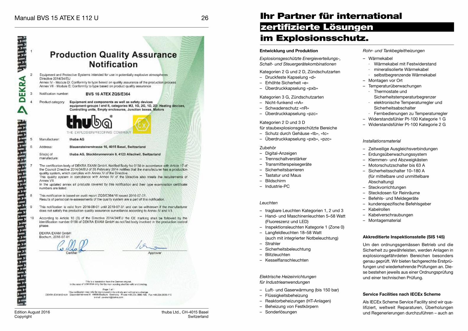
Ihr Partner für internationalzertifizierte Lösungenim Explosionsschutz.
Rohr- und Tankbegleitheizungen
– Wärmekabel · Wärmekabel mit Festwiderstand · mineralisolierte Wärmekabel · selbstbegrenzende Wärmekabel– Montagen vor Ort– Temperaturüberwachungen · Thermostate und Sicherheitstemperaturbegrenzer · elektronische Temperaturregler und Sicherheitsabschalter · Fernbedienungen zu Temperaturregler– Widerstandsfühler Pt-100 Kategorie 1 G– Widerstandsfühler Pt-100 Kategorie 2 G
Installationsmaterial
– Zeitweilige Ausgleichsverbindungen– Erdungsüberwachungssystem– Klemmen- und Abzweigkästen– Motorschutzschalter bis 63 A– Sicherheitsschalter 10–180 A (für mittelbare und unmittelbare
Abschaltung)– Steckvorrichtungen– Steckdosen für Reinräume– Befehls- und Meldegeräte– kundenspezifische Befehlsgeber– Kabelrollen– Kabelverschraubungen– Montagematerial
Akkreditierte Inspektionsstelle (SIS 145)
Um den ordnungsgemässen Betrieb und dieSicherheit zu gewährleisten, werden Anlagen inexplosionsgefährdeten Bereichen besondersgenau geprüft. Wir bieten fachgerechte Erstprü-fungen und wiederkehrende Prüfungen an. Die-se bestehen jeweils aus einer Ordnungsprüfungund einer technischen Prüfung.
Service Facilities nach IECEx Scheme
Als IECEx Scheme Service Facility sind wir qua-lifiziert, weltweit Reparaturen, Überholungenund Regenerierungen durchzuführen – auch an
Entwicklung und Produktion
Explosionsgeschützte Energieverteilungs-,
Schalt- und Steuergerätekombinationen
Kategorien 2 G und 2 D, Zündschutzarten– Druckfeste Kapselung «d»– Erhöhte Sicherheit «e»– Überdruckkapselung «pxb»
Kategorien 3 G, Zündschutzarten– Nicht-funkend «nA» – Schwadenschutz «nR» – Überdruckkapselung «pzc»
Kategorien 2 D und 3 Dfür staubexplosionsgeschützte Bereiche– Schutz durch Gehäuse «tb», «tc»– Überdruckkapselung «pxb», «pzc»
Zubehör – Digital-Anzeigen– Trennschaltverstärker– Transmitterspeisegeräte– Sicherheitsbarrieren– Tastatur und Maus– Bildschirm– Industrie-PC
Leuchten
– tragbare Leuchten Kategorien 1, 2 und 3– Hand- und Maschinenleuchten 5–58 Watt (Fluoreszenz und LED)– Inspektionsleuchten Kategorie 1 (Zone 0)– Langfeldleuchten 18–58 Watt
(auch mit integrierter Notbeleuchtung)– Strahler– Sicherheitsbeleuchtung – Blitzleuchten– Kesselflanschleuchten
Elektrische Heizeinrichtungen
für Industrieanwendungen
– Luft- und Gaserwärmung (bis 150 bar)– Flüssigkeitsbeheizung– Reaktorbeheizungen (HT-Anlagen)– Beheizung von Festkörpern– Sonderlösungen
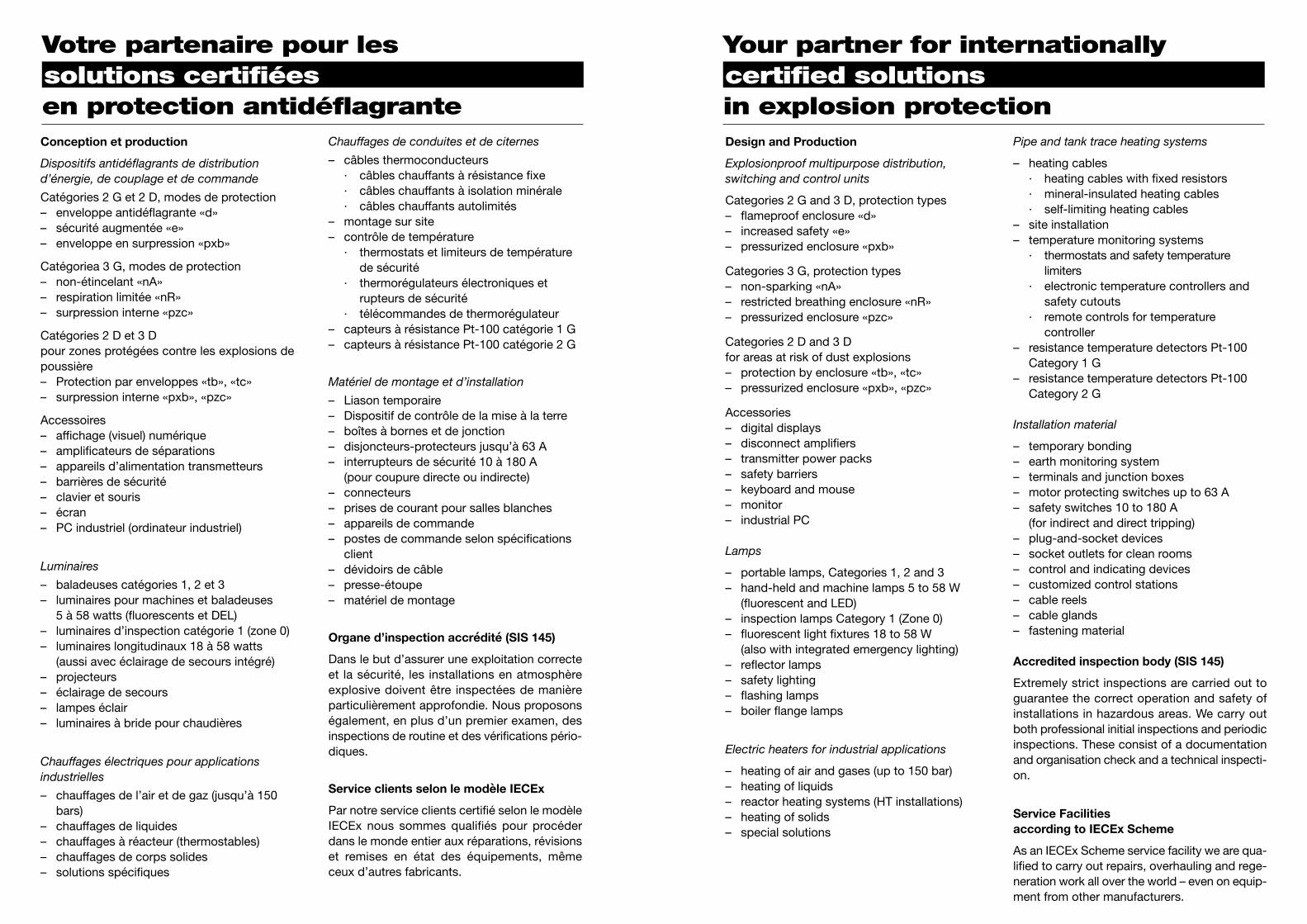
Your partner for internationallycertified solutionsin explosion protection
Votre partenaire pour lessolutions certifiéesen protection antidéflagrante
Chauffages de conduites et de citernes
– câbles thermoconducteurs· câbles chauffants à résistance fixe· câbles chauffants à isolation minérale
· câbles chauffants autolimités– montage sur site– contrôle de température · thermostats et limiteurs de température
de sécurité · thermorégulateurs électroniques et rupteurs de sécurité · télécommandes de thermorégulateur– capteurs à résistance Pt-100 catégorie 1 G– capteurs à résistance Pt-100 catégorie 2 G
Matériel de montage et d’installation
– Liason temporaire– Dispositif de contrôle de la mise à la terre– boîtes à bornes et de jonction– disjoncteurs-protecteurs jusqu’à 63 A– interrupteurs de sécurité 10 à 180 A (pour coupure directe ou indirecte)– connecteurs– prises de courant pour salles blanches– appareils de commande– postes de commande selon spécifications
client– dévidoirs de câble– presse-étoupe– matériel de montage
Organe d’inspection accrédité (SIS 145)
Dans le but d’assurer une exploitation correcteet la sécurité, les installations en atmosphèreexplosive doivent être inspectées de manièreparticulièrement approfondie. Nous proposonségalement, en plus d’un premier examen, desinspections de routine et des vérifications pério-diques.
Service clients selon le modèle IECEx
Par notre service clients certifié selon le modèleIECEx nous sommes qualifiés pour procéderdans le monde entier aux réparations, révisionset remises en état des équipements, mêmeceux d’autres fabricants.
Conception et production
Dispositifs antidéflagrants de distributiond’éner gie, de couplage et de commande
Catégories 2 G et 2 D, modes de protection– enveloppe antidéflagrante «d»– sécurité augmentée «e»– enveloppe en surpression «pxb»
Catégoriea 3 G, modes de protection– non-étincelant «nA» – respiration limitée «nR»– surpression interne «pzc»
Catégories 2 D et 3 Dpour zones protégées contre les explosions depoussière– Protection par enveloppes «tb», «tc»– surpression interne «pxb», «pzc»
Accessoires– affichage (visuel) numérique – amplificateurs de séparations– appareils d’alimentation transmetteurs– barrières de sécurité– clavier et souris– écran– PC industriel (ordinateur industriel)
Luminaires
– baladeuses catégories 1, 2 et 3– luminaires pour machines et baladeuses 5 à 58 watts (fluorescents et DEL)– luminaires d’inspection catégorie 1 (zone 0)– luminaires longitudinaux 18 à 58 watts (aussi avec éclairage de secours intégré)– projecteurs – éclairage de secours – lampes éclair– luminaires à bride pour chaudières
Chauffages électriques pour applications industrielles
– chauffages de l’air et de gaz (jusqu’à 150bars)
– chauffages de liquides– chauffages à réacteur (thermostables)– chauffages de corps solides– solutions spécifiques
Pipe and tank trace heating systems
– heating cables · heating cables with fixed resistors · mineral-insulated heating cables · self-limiting heating cables– site installation – temperature monitoring systems · thermostats and safety temperature
limiters · electronic temperature controllers and safety cutouts · remote controls for temperature
controller– resistance temperature detectors Pt-100
Category 1 G– resistance temperature detectors Pt-100
Category 2 G
Installation material
– temporary bonding– earth monitoring system– terminals and junction boxes – motor protecting switches up to 63 A– safety switches 10 to 180 A (for indirect and direct tripping)– plug-and-socket devices– socket outlets for clean rooms – control and indicating devices– customized control stations– cable reels– cable glands– fastening material
Accredited inspection body (SIS 145)
Extremely strict inspections are carried out toguarantee the correct operation and safety ofinstallations in hazardous areas. We carry outboth professional initial inspections and periodicinspections. These consist of a documentationand organisation check and a technical inspecti-on.
Service Facilities according to IECEx Scheme
As an IECEx Scheme service facility we are qua-lified to carry out repairs, overhauling and rege-neration work all over the world – even on equip-ment from other manufacturers.
Design and Production
Explosionproof multipurpose distribution,
switching and control units
Categories 2 G and 3 D, protection types– flameproof enclosure «d»– increased safety «e»– pressurized enclosure «pxb»
Categories 3 G, protection types– non-sparking «nA»– restricted breathing enclosure «nR»– pressurized enclosure «pzc»
Categories 2 D and 3 Dfor areas at risk of dust explosions– protection by enclosure «tb», «tc»– pressurized enclosure «pxb», «pzc»
Accessories– digital displays– disconnect amplifiers– transmitter power packs– safety barriers– keyboard and mouse– monitor– industrial PC
Lamps
– portable lamps, Categories 1, 2 and 3– hand-held and machine lamps 5 to 58 W
(fluorescent and LED)– inspection lamps Category 1 (Zone 0)– fluorescent light fixtures 18 to 58 W
(also with integrated emergency lighting)– reflector lamps– safety lighting – flashing lamps– boiler flange lamps
Electric heaters for industrial applications
– heating of air and gases (up to 150 bar)– heating of liquids– reactor heating systems (HT installations)– heating of solids – special solutions
thuba Ltd.CH-4015 Basel
Phone +41 61 307 80 00 Fax +41 61 307 80 10E-mail [email protected] www.thuba.com