Embed Size (px)
DESCRIPTION
Manual EN: Metz Mecablitz 44 AF-4i NInstrukcja EN: Metz Mecablitz 44 AF-4i N
Citation preview
MECABLITZ 44 AF-4/4i NBedienungsanleitung Mode d’emploiGebruiksaanwijzing Operating instructionManuale istruzioni Manual de instrucciones
1. Sicherheitshinweise . . . . . . . . . . . . . . . . . . . . . . . . . . . . . . . . . .3Tabelle 1 . . . . . . . . . . . . . . . . . . . . . . . . . . . . . . . . . . . . . . . . . .4
2. Blitzgerät vorbereiten . . . . . . . . . . . . . . . . . . . . . . . . . . . . . . . .52.1 Montage des Blitzgerätes . . . . . . . . . . . . . . . . . . . . . . . . . . . . . .52.1.1 Blitzgerät auf der Kamera montieren . . . . . . . . . . . . . . . . . . . . . .52.1.2 Blitzgerät von der Kamera abnehmen . . . . . . . . . . . . . . . . . . . . .52.2 Stromversorgung . . . . . . . . . . . . . . . . . . . . . . . . . . . . . . . . . . . .52.2.1 Batterien- bzw. Akkuauswahl . . . . . . . . . . . . . . . . . . . . . . . . . . .52.2.2 Batterien austauschen . . . . . . . . . . . . . . . . . . . . . . . . . . . . . . . .52.3 Ein- und Ausschalten des Blitzgerätes . . . . . . . . . . . . . . . . . . . . .52.4 Automatische Geräteabschaltung / Auto - OFF . . . . . . . . . . . . . .53. Programmblitzautomatik . . . . . . . . . . . . . . . . . . . . . . . . . . . . . .64. Betriebsarten des Blitzgerätes . . . . . . . . . . . . . . . . . . . . . . . . . .74.1 TTL-Blitzbetrieb . . . . . . . . . . . . . . . . . . . . . . . . . . . . . . . . . . . . .74.1.1 E-TTL-Blitzbetrieb . . . . . . . . . . . . . . . . . . . . . . . . . . . . . . . . . . . .74.1.2 Automatisches Aufhellblitzen bei Tageslicht mit TTL / E-TTL . . . . . .74.1.3 3D-Multisensor-Aufhellblitzen . . . . . . . . . . . . . . . . . . . . . . . . . . .84.2 D-TTL-Blitzbetrieb . . . . . . . . . . . . . . . . . . . . . . . . . . . . . . . . . . . .94.2.1 D-TTL-3D-Blitzbetrieb . . . . . . . . . . . . . . . . . . . . . . . . . . . . . . . . .94.3 i-TTL-Blitzbetrieb . . . . . . . . . . . . . . . . . . . . . . . . . . . . . . . . . . . .94.3.1 i-TTL-BL-Blitzbetrieb . . . . . . . . . . . . . . . . . . . . . . . . . . . . . . . . .104.4 Manuelle TTL-Blitzbelichtungskorrektur . . . . . . . . . . . . . . . . . . . .104.5 Belichtungskontrollanzeige im TTL-Blitzbetrieb . . . . . . . . . . . . . .114.6 Unterbelichtungsanzeige im TTL-Blitzbetrieb . . . . . . . . . . . . . . . .114.7 Manueller Blitzbetrieb . . . . . . . . . . . . . . . . . . . . . . . . . . . . . . .114.7.1 Manueller Blitzbetrieb M mit voller Lichtleistung . . . . . . . . . . . . .114.7.2 Manueller Blitzbetrieb MLo mit voller Teillichtleistung . . . . . . . . .124.8 Blitztechniken . . . . . . . . . . . . . . . . . . . . . . . . . . . . . . . . . . . . .124.8.1 Indirektes Blitzen . . . . . . . . . . . . . . . . . . . . . . . . . . . . . . . . . . .124.8.2 Nahaufnahmen / Makroaufnahmen . . . . . . . . . . . . . . . . . . . . .134.9 Blitzsynchronisation . . . . . . . . . . . . . . . . . . . . . . . . . . . . . . . . .134.9.1 Normalsynchronisation . . . . . . . . . . . . . . . . . . . . . . . . . . . . . .134.9.2 Synchronisation auf den 2.Verschlussvorhang (REAR-Betrieb) . . .13
4.9.3 Langzeitsynchronisation / SLOW . . . . . . . . . . . . . . . . . . . . . . .145. Blitzgerät- und Kamerafunktionen . . . . . . . . . . . . . . . . . . . . . .145.1 Blitzbereitschaftsanzeige . . . . . . . . . . . . . . . . . . . . . . . . . . . . .145.2 Automatische Blitzsynchronzeitsteuerung . . . . . . . . . . . . . . . . . .145.3 Anzeigen im Kamerasucher . . . . . . . . . . . . . . . . . . . . . . . . . . .145.4 Anzeigen im LC-Display . . . . . . . . . . . . . . . . . . . . . . . . . . . . . .155.4.1 Reichweitenanzeige im TTL-Blitzbetrieb . . . . . . . . . . . . . . . . . . .155.4.2 Reichweitenanzeige im manuellen Blitzbetrieb M bzw. MLo . . . .155.4.3 Überschreitung des Anzeigebereichs . . . . . . . . . . . . . . . . . . . . .155.4.4 Ausblendung der Reichweitenanzeige . . . . . . . . . . . . . . . . . . . .155.4.5 Error-Anzeige „FEE“ im LC-Display des Blitzgerätes . . . . . . . . . .155.4.6 Leitzahlanzeige bei Objektiven ohne CPU . . . . . . . . . . . . . . . . .155.4.7 Meter-Feet-Umschaltung (m-ft) . . . . . . . . . . . . . . . . . . . . . . . . .165.5 Blitzreichweitenbestimmung mit Leitzahlentabelle . . . . . . . . . . . .165.6 LC-Display-Beleuchtung . . . . . . . . . . . . . . . . . . . . . . . . . . . . . .175.7 Motor-Zoom-Reflektor . . . . . . . . . . . . . . . . . . . . . . . . . . . . . . .175.7.1 „Auto-Zoom“ . . . . . . . . . . . . . . . . . . . . . . . . . . . . . . . . . . . . .175.7.2 Manueller Zoom-Betrieb „M. Zoom“ . . . . . . . . . . . . . . . . . . . . .175.7.3 Manueller Zoom-Betrieb statt „Auto-Zoom“ . . . . . . . . . . . . . . . .175.7.4 Extended-Zoom-Betrieb . . . . . . . . . . . . . . . . . . . . . . . . . . . . . .185.8 Autofokus-Messblitz . . . . . . . . . . . . . . . . . . . . . . . . . . . . . . . . .185.9 Vorblitz gegen den „Rote-Augen-Effekt“ . . . . . . . . . . . . . . . . . .195.10 Automatikblitz / Zündungssteuerung . . . . . . . . . . . . . . . . . . . . .195.11 Zurück zur Grundeinstellung . . . . . . . . . . . . . . . . . . . . . . . . . . .196. Spezielle Kamerahinweise . . . . . . . . . . . . . . . . . . . . . . . . . . . .206.1 Im Blitzbetrieb nicht unterstützte Sonderfunktionen . . . . . . . . . . .206.1.1 Programmverschiebung / Programm-Shift . . . . . . . . . . . . . . . . .207. Sonderzubehör . . . . . . . . . . . . . . . . . . . . . . . . . . . . . . . . . . . .208. Hilfe bei Störungen . . . . . . . . . . . . . . . . . . . . . . . . . . . . . . . . .219. Wartung und Pflege . . . . . . . . . . . . . . . . . . . . . . . . . . . . . . . .2110. Technische Daten . . . . . . . . . . . . . . . . . . . . . . . . . . . . . . . . . . .22Garantiebestimmungen . . . . . . . . . . . . . . . . . . . . . . . . . . . . . . . . . . . .23Leitzahlentabelle für TTL und volle Lichtleistung M im Meter-System . . . .134
�
2
VorwortVielen Dank, dass Sie sich für ein Metz Produkt entschieden haben. Wir freuen uns, Sie als Kunde begrüßen zu dürfen.Natürlich können Sie es kaum erwarten, das Blitzgerät in Betrieb zu nehmen.Es lohnt sich aber, die Bedienungsanleitung zu lesen, denn nur so lernen Sie,mit dem Gerät problemlos umzugehen.Dieses Blitzgerät ist für Nikon-Kameras mit TTL–, D-TTL und i–TTL–Blitzsteuerunggeeignet (i-TTL nur mit 44 AF-4i N). Für Kameras anderer Hersteller ist das Blitz-gerät nicht geeignet!
Schlagen Sie bitte auch die Bildseite des Umschlages am Ende derAnleitung auf.
1. Sicherheitshinweise• Das Blitzgerät ist ausschließlich zur Verwendung im fotografischen Be-
reich vorgesehen und zugelassen!• In Umgebung von entflammbaren Gasen oder Flüssigkeiten (Benzin,
Lösungsmittel etc.) darf das Blitzgerät keinesfalls ausgelöst werden!EXPLOSIONSGEFAHR!
• Auto-, Bus-, Fahrrad-, Motorrad- oder Zugfahrer etc. niemals währendder Fahrt mit einem Blitzgerät fotografieren. Durch die Blendung kannder Fahrer einen Unfall verursachen!
• Lösen Sie in unmittelbarer Nähe der Augen keinesfalls einen Blitz aus!Ein Blitzlicht direkt vor den Augen von Personen und Tieren kann zurNetzhautschädigung führen und schwere Sehstörungen verursachen - bishin zur Blindheit!
• Nur die in der Bedienungsanleitung bezeichneten und zugelassenenStromquellen verwenden!
• Batterien/Akkus nicht übermäßiger Wärme wie Sonnenschein, Feueroder dergleichen aussetzen!
• Verbrauchte Batterien/Akkus nicht ins Feuer werfen!
�
• Aus verbrauchten Batterien kann Lauge austreten, was zur Beschädigungder Kontakte führt. Verbrauchte Batterien deshalb immer aus dem Gerätentnehmen.
• Trockenbatterien dürfen nicht geladen werden.• Blitz- und Ladegerät nicht Tropf- und Spritzwasser (z.B. Regen) ausset-
zen!• Schützen Sie Ihr Blitzgerät vor großer Hitze und hoher Luftfeuchtigkeit!
Blitzgerät nicht im Handschuhfach des Autos aufbewahren!• Beim Auslösen eines Blitzes darf sich kein lichtundurchlässiges Material
unmittelbar vor oder direkt auf der Reflektorscheibe befinden. Die Re-flektorscheibe darf nicht verunreinigt sein. Bei Nichtbeachtung kann es,durch die hohe Energie des Blitzlichtes, zu Verbrennungen des Materialsbzw. der Reflektorscheibe führen.
• Nach mehrfachem Blitzen nicht die Reflektorscheibe berühren.Verbrennungsgefahr!
• Blitzgerät nicht zerlegen! HOCHSPANNUNG!Im Geräteinneren befinden sich keine Bauteile, die von einem Laienrepariert werden können.
• Bei Serienblitzaufnahmen mit voller Lichtleistung und den kurzen Blitz-folgezeiten des NC-Akku-Betriebes ist darauf zu achten, dass nach je-weils 15 Blitzen eine Pause von mindestens 10 Minuten eingehaltenwird. Somit vermeiden Sie eine Überlastung des Gerätes.
• Das Blitzgerät darf nur dann zusammen mit einem in die Kamera einge-bauten Blitzgerät verwendet werden, wenn dieses vollständig ausge-klappt werden kann!
• Bei raschem Temperaturwechsel kann Feuchtigkeitsbeschlag auftreten.Gerät akklimatisieren lassen!
• Keine schadhaften Batterien oder Akkus verwenden!
3
��
�
4
Dedicated-BlitzfunktionenDie Dedicated-Blitzfunktionen sind speziell auf das Kamerasystem abge-stimmte Blitzfunktionen. In Abhängigkeit vom Kameratyp werden dabei ver-schiedene Blitzfunktionen unterstützt.Folgende Dedicated-Blitzfunktionen werden vom Blitzgerät unterstützt:• Blitzbereitschaftsanzeige im Kamerasucher / Kameradisplay• Belichtungskontrollanzeige im Kamerasucher / Kameradisplay• Unterbelichtungsanzeige im LC-Display des Blitzgerätes• Automatische Blitzsynchronzeitsteuerung• TTL-Blitzsteuerung (Standard-TTL ohne Messvorblitz)• Automatische Aufhellblitzsteuerung• Matrixgesteuerter TTL-Aufhellblitzbetrieb• 3D-Multisensor-Aufhellblitzbetrieb• D-TTL-Blitzbetrieb und D-TTL-3D-Blitzbetrieb• i-TTL-Blitzbetrieb und i-TTL-BL-Blitzbetrieb (nur mit 44 AF-4i N)• Manuelle TTL-Blitzbelichtungskorrektur• Synchronisation auf den 1. oder 2.Verschlussvorhang (REAR)• Automatische Motor-Zoom-Steuerung• Automatische AF-Messblitzsteuerung• Blitzreichweitenanzeige• Programmblitzautomatik• Vorblitzfunktion zur Reduzierung des Rote-Augen-Effektes• Zündungssteuerung / Auto-Flash• Wake-Up-Funktion für das Blitzgerät
Im Rahmen dieser Bedienungsanleitung ist es nicht möglich, alle Ka-meratypen mit den einzelnen Blitzfunktionen detailliert zu beschrei-ben. Beachten Sie deshalb die Hinweise zum Blitzbetrieb in derBedienungsanleitung Ihrer Kamera, welche Blitzfunktionen von IhremKameratyp unterstützt werden bzw. an der Kamera selbst eingestelltwerden müssen!
Die Nikon-Kameras können hinsichtlich der Dedicated-Blitzfunktionen infolgende Gruppen aufgeteilt werden:
Kameras aus Gruppe A Kameras ohne digitale Datenübertragung zum Blitzgerätz.B. Nikon F601, F601M, F60, F50, FM-3ADigitale Kompaktkameras “Nikon - Coolpix”
Kameras aus Gruppe B Kameras mit digitaler Datenübertragung zum Blitzgerätz.B. Nikon F4, F4s, F801, F801s, Pronea 600i, 6
Kameras aus Gruppe C Kameras mit digitaler Datenübertragung zumBlitzgerät und 3D-Multisensor-Aufhellblitzbetriebz.B. Nikon F5, F100, F90X, F90, F80, F70
Kameras aus Gruppe D Digitale Nikon-Spiegelreflexkameras mit D-TTL-Blitzbetriebz.B. D1, D1x, D1H, D100
Kameras aus Gruppe E Digitale Nikon-Spiegelreflexkameras mit i-TTL-Blitzbetriebz.B. D70(Der i-TTL-Blitzbetrieb wird nur vom 44 AF-4i Nunterstützt )
Tabelle 1
�
2. Blitzgerät vorbereiten2.1 Montage des Blitzgerätes2.1.1 Blitzgerät auf der Kamera montieren
Kamera und Blitzgerät vor der Montage oder Demontage ausschalten.
• Rändelmutter bis zum Anschlag gegen das Blitzgerät drehen. Der Sicherungs-stift im Fuß ist jetzt vollkommen im Gehäuse des Blitzgerätes versenkt.
• Blitzgerät mit dem Anschlussfuß bis zum Anschlag in den Zubehörschuhder Kamera schieben.
• Rändelmutter bis zum Anschlag gegen das Kameragehäuse drehen und dasBlitzgerät festklemmen. Bei Kameragehäusen, die kein Sicherungsloch auf-weisen, versenkt sich der federgelagerte Sicherungsstift im Gehäuse desBlitzgerätes, damit die Oberfläche nicht beschädigt wird.
2.1.2 Blitzgerät von der Kamera abnehmenKamera und Blitzgerät vor der Montage oder Demontage ausschalten.
• Rändelmutter bis zum Anschlag gegen das Blitzgerät drehen.• Blitzgerät aus dem Zubehörschuh der Kamera herausziehen.
2.2 Stromversorgung2.2.1 Batterien- bzw. AkkuauswahlDas Blitzgerät kann wahlweise betrieben werden mit:• 4 NC-Akkus 1,2 V, Typ IEC KR 15/51 (KR6 / AA / Mignon), sie bieten sehr
kurze Blitzfolgezeiten und sparsamen Betrieb, da sie wiederaufladbar sind.• 4 Nickel-Metall-Hydrid Akkus 1,2 V, Typ HR6 (AA / Mignon), deutlich höhere
Kapazität als NC-Akku und weniger umweltschädlich, da cadmiumfrei.• 4 Alkali-Mangan-Trockenbatterien 1,5 V, Typ IEC LR6 (AA / Mignon), war-
tungsfreie Stromquelle für gemäßigte Leistungsanforderungen.• 4 Lithium-Batterien 1,5 V, Typ IEC FR6 L91 (AA / Mignon), wartungsfreie
Stromquelle mit hoher Kapazität und geringer Selbstentladung.
�
�
Wenn Sie das Blitzgerät längere Zeit nicht benutzen, entfernen Siebitte die Batterien aus dem Gerät.
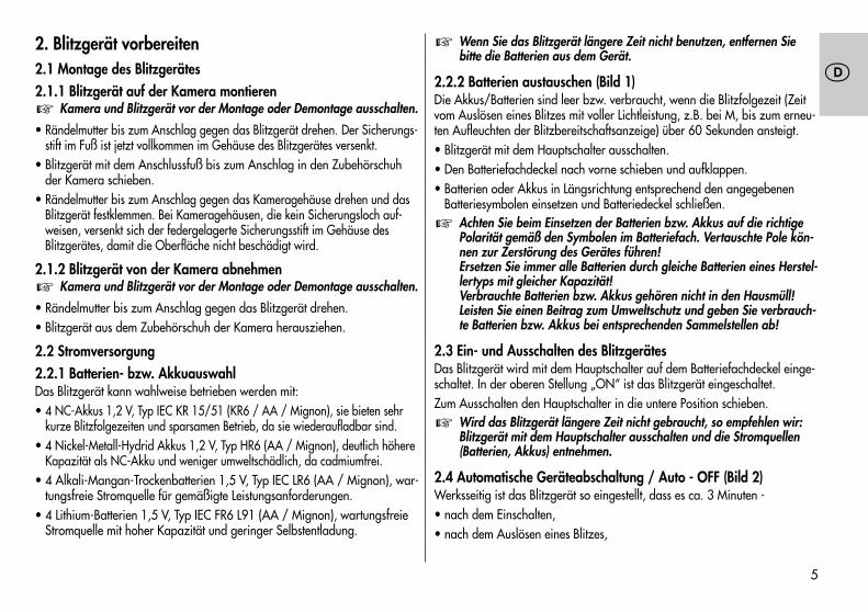
2.2.2 Batterien austauschen (Bild 1)Die Akkus/Batterien sind leer bzw. verbraucht, wenn die Blitzfolgezeit (Zeitvom Auslösen eines Blitzes mit voller Lichtleistung, z.B. bei M, bis zum erneu-ten Aufleuchten der Blitzbereitschaftsanzeige) über 60 Sekunden ansteigt.• Blitzgerät mit dem Hauptschalter ausschalten.• Den Batteriefachdeckel nach vorne schieben und aufklappen.• Batterien oder Akkus in Längsrichtung entsprechend den angegebenen
Batteriesymbolen einsetzen und Batteriedeckel schließen.Achten Sie beim Einsetzen der Batterien bzw. Akkus auf die richtigePolarität gemäß den Symbolen im Batteriefach. Vertauschte Pole kön-nen zur Zerstörung des Gerätes führen!Ersetzen Sie immer alle Batterien durch gleiche Batterien eines Herstel-lertyps mit gleicher Kapazität!Verbrauchte Batterien bzw. Akkus gehören nicht in den Hausmüll!Leisten Sie einen Beitrag zum Umweltschutz und geben Sie verbrauch-te Batterien bzw. Akkus bei entsprechenden Sammelstellen ab!
2.3 Ein- und Ausschalten des Blitzgerätes Das Blitzgerät wird mit dem Hauptschalter auf dem Batteriefachdeckel einge-schaltet. In der oberen Stellung „ON“ ist das Blitzgerät eingeschaltet.Zum Ausschalten den Hauptschalter in die untere Position schieben.
Wird das Blitzgerät längere Zeit nicht gebraucht, so empfehlen wir: Blitzgerät mit dem Hauptschalter ausschalten und die Stromquellen(Batterien, Akkus) entnehmen.
2.4 Automatische Geräteabschaltung / Auto - OFF (Bild 2)Werksseitig ist das Blitzgerät so eingestellt, dass es ca. 3 Minuten -• nach dem Einschalten,• nach dem Auslösen eines Blitzes,
�
�
�
5
��
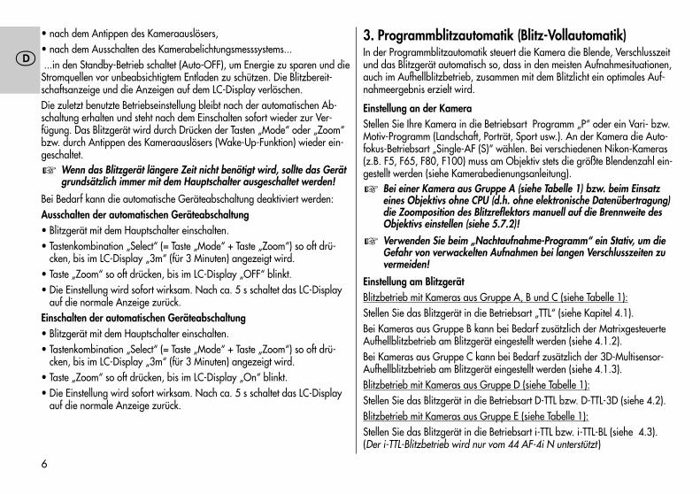
• nach dem Antippen des Kameraauslösers,• nach dem Ausschalten des Kamerabelichtungsmesssystems......in den Standby-Betrieb schaltet (Auto-OFF), um Energie zu sparen und dieStromquellen vor unbeabsichtigtem Entladen zu schützen. Die Blitzbereit-schaftsanzeige und die Anzeigen auf dem LC-Display verlöschen.Die zuletzt benutzte Betriebseinstellung bleibt nach der automatischen Ab-schaltung erhalten und steht nach dem Einschalten sofort wieder zur Ver-fügung. Das Blitzgerät wird durch Drücken der Tasten „Mode“ oder „Zoom“bzw. durch Antippen des Kameraauslösers (Wake-Up-Funktion) wieder ein-geschaltet.
Wenn das Blitzgerät längere Zeit nicht benötigt wird, sollte das Gerätgrundsätzlich immer mit dem Hauptschalter ausgeschaltet werden!
Bei Bedarf kann die automatische Geräteabschaltung deaktiviert werden:Ausschalten der automatischen Geräteabschaltung• Blitzgerät mit dem Hauptschalter einschalten.• Tastenkombination „Select“ (= Taste „Mode“ + Taste „Zoom“) so oft drü-
cken, bis im LC-Display „3m“ (für 3 Minuten) angezeigt wird.• Taste „Zoom“ so oft drücken, bis im LC-Display „OFF“ blinkt.• Die Einstellung wird sofort wirksam. Nach ca. 5 s schaltet das LC-Display
auf die normale Anzeige zurück.Einschalten der automatischen Geräteabschaltung• Blitzgerät mit dem Hauptschalter einschalten.• Tastenkombination „Select“ (= Taste „Mode“ + Taste „Zoom“) so oft drü-
cken, bis im LC-Display „3m“ (für 3 Minuten) angezeigt wird.• Taste „Zoom“ so oft drücken, bis im LC-Display „On“ blinkt.• Die Einstellung wird sofort wirksam. Nach ca. 5 s schaltet das LC-Display
auf die normale Anzeige zurück.
�
3. Programmblitzautomatik (Blitz-Vollautomatik)In der Programmblitzautomatik steuert die Kamera die Blende, Verschlusszeitund das Blitzgerät automatisch so, dass in den meisten Aufnahmesituationen,auch im Aufhellblitzbetrieb, zusammen mit dem Blitzlicht ein optimales Auf-nahmeergebnis erzielt wird.
Einstellung an der KameraStellen Sie Ihre Kamera in die Betriebsart Programm „P“ oder ein Vari- bzw.Motiv-Programm (Landschaft, Porträt, Sport usw.). An der Kamera die Auto-fokus-Betriebsart „Single-AF (S)“ wählen. Bei verschiedenen Nikon-Kameras(z.B. F5, F65, F80, F100) muss am Objektiv stets die größte Blendenzahl ein-gestellt werden (siehe Kamerabedienungsanleitung).
Bei einer Kamera aus Gruppe A (siehe Tabelle 1) bzw. beim Einsatzeines Objektivs ohne CPU (d.h. ohne elektronische Datenübertragung)die Zoomposition des Blitzreflektors manuell auf die Brennweite desObjektivs einstellen (siehe 5.7.2)!
Verwenden Sie beim „Nachtaufnahme-Programm“ ein Stativ, um dieGefahr von verwackelten Aufnahmen bei langen Verschlusszeiten zuvermeiden!
Einstellung am BlitzgerätBlitzbetrieb mit Kameras aus Gruppe A, B und C (siehe Tabelle 1):Stellen Sie das Blitzgerät in die Betriebsart „TTL“ (siehe Kapitel 4.1).Bei Kameras aus Gruppe B kann bei Bedarf zusätzlich der MatrixgesteuerteAufhellblitzbetrieb am Blitzgerät eingestellt werden (siehe 4.1.2).Bei Kameras aus Gruppe C kann bei Bedarf zusätzlich der 3D-Multisensor-Aufhellblitzbetrieb am Blitzgerät eingestellt werden (siehe 4.1.3).Blitzbetrieb mit Kameras aus Gruppe D (siehe Tabelle 1):Stellen Sie das Blitzgerät in die Betriebsart D-TTL bzw. D-TTL-3D (siehe 4.2).Blitzbetrieb mit Kameras aus Gruppe E (siehe Tabelle 1):Stellen Sie das Blitzgerät in die Betriebsart i-TTL bzw. i-TTL-BL (siehe 4.3).(Der i-TTL-Blitzbetrieb wird nur vom 44 AF-4i N unterstützt )
�
�
6
��
Sowie Sie obige Einstellungen vorgenommen haben, können Sie mit IhrenBlitzlichtaufnahmen beginnen, wenn das Blitzgerät seine Blitzbereitschaftanzeigt (siehe 5.1)!
4. Betriebsarten des Blitzgerätes4.1 TTL-Blitzbetrieb (Bild 3)Im TTL-Blitzbetrieb erreichen Sie auf einfache Art sehr gute Blitzlichtauf-nahmen. In dieser Blitzbetriebsart wird die Belichtungsmessung von einemSensor in der Kamera vorgenommen. Dieser misst das durchs Objektiv(TTL = „Trough The Lens“) einfallende Licht. Beim Erreichen der erforderlichenLichtmenge sendet die Kameraelektronik ein Stopp-Signal an das Blitzgerätund die Lichtabstrahlung wird sofort unterbrochen. Der Vorteil dieses Blitz-betriebes liegt darin, dass alle Faktoren, welche die Belichtung beeinflussen(Aufnahmefilter, Blenden- und Brennweitenänderungen bei Zoom-Objektiven,Auszugsverlängerungen für Nahaufnahmen usw.), automatisch bei der Re-gelung des Blitzlichtes berücksichtigt werden. Sie brauchen sich nicht um dieBlitzeinstellung zu kümmern, die Kameraelektronik sorgt automatisch für dierichtige Blitzlichtdosierung. Für die Reichweite des Blitzlichtes beachten Siedie Anzeige im LC-Display des Blitzgerätes (siehe 5.4) bzw. die Hinweise inKapitel 5.5. Bei einer korrekt belichteten Blitzlichtaufnahme erscheint für ca.3 s am LC-Display des Blitzgerätes die „o.k.“-Anzeige (siehe 4.5).Der TTL-Blitzbetrieb wird von allen Kamerabetriebsarten (z.B. Programm „P“,Zeitautomatik „A“, Blendenautomatik „S“, Vari- bzw. Motiv-Programme,Manuell „M“ usw.) unterstützt.
Zum Testen der TTL-Funktion muss sich bei Analog-Kameras ein Film inder Kamera befinden! Beachten Sie, ob es für Ihre Kamera Einschrän-kungen hinsichtlich der Filmempfindlichkeit bzw. ISO-Zahl (z.B. maxi-mal ISO 1000) für den TTL-Blitzbetrieb gibt (siehe Kamerabedienungs-anleitung)!Verschiedene digitale SLR-Kameras unterstützen den normalen Stan-dard-TTL-Blitzbetrieb analoger Kameras nicht! Beim Blitzbetrieb mitKameras aus Gruppe D (siehe Tabelle 1) muss am Blitzgerät derD–TTL– bzw. D-TTL-3D-Blitzbetrieb eingestellt werden (siehe Kapi-tel 4.2). Beim Blitzbetrieb mit Kameras aus Gruppe E (siehe Tabelle 1)
�
muss am Blitzgerät der i-TTL– bzw. i-TTL-BL-Blitzbetrieb(nur mit 44 AF-4i N) eingestellt werden (siehe Kapitel 4.3)!
Einstellvorgang für den TTL-Blitzbetrieb• Blitzgerät auf die Kamera montieren.• Blitzgerät und Kamera einschalten.• Taste „Mode“ so oft drücken, bis im LC-Display „TTL“ blinkt.• Die Einstellung wird sofort wirksam. Nach ca. 5 s schaltet das LC-Display
auf die normale Anzeige zurück.Bei starken Kontrastunterschieden, z.B. dunkles Objekt im Schnee,kann eine Belichtungskorrektur erforderlich sein (siehe 4.4).
4.1.1 Automatisches TTL-Aufhellblitzen bei Tageslicht (Bild 5 und 6)Bei den meisten Kameratypen wird in der Programmautomatik P und denVari- bzw. Motiv-Programmen bei Tageslicht der automatische Aufhellblitz-betrieb aktiviert (siehe Kamerabedienungsanleitung).Mit dem Aufhellblitz können Sie lästige Schatten beseitigen und bei Gegen-lichtaufnahmen eine ausgewogene Belichtung zwischen Motiv und Bildhinter-grund erreichen. Ein computergesteuertes Messsystem der Kamera sorgt fürdie geeignete Kombination von Verschlusszeit, Arbeitsblende und Blitzleis-tung.
Achten Sie darauf, dass die Gegenlichtquelle nicht direkt ins Objektivscheint. Das TTL–Messsystem der Kamera würde dadurch getäuscht!
Eine Einstellung oder Anzeige für den automatischen TTL-Aufhellblitzbetriebam Blitzgerät erfolgt in diesem Fall nicht.
4.1.2 Matrixgesteuerter TTL-AufhellblitzbetriebIn dieser Blitzbetriebsart werden Motiv- und Hintergrundbeleuchtung auto-matisch aufeinander abgestimmt, ohne dass das Motiv selbst überbelichtetwird. Die Belichtungseinstellung für das Umgebungslicht wird von der Kame-ra mit Matrixmessung ermittelt.Verschiedene Nikon-Kameras unterstützen den Matrixgesteuerten TTL–Auf-hell-Blitzbetrieb (siehe Kamerabedienungsanleitung und Tabelle 1).
�
�
7
��
Bei einigen Kameras (z.B. F4, F4s) wird der MatrixgesteuerteTTL-Aufhellblitzbetrieb bei SPOT-Belichtungsmessung nicht unterstützt!Diese Blitzbetriebsart wird dabei automatisch gelöscht bzw. lässt sichnicht aktivieren. Es wird dann der normale TTL-Blitzbetrieb ausgeführt.
Mit Kameras der Gruppe A (siehe Tabelle 1) erfolgt die Einstellung desMatrixgesteuerten TTL-Aufhellblitzbetriebes an der Kamera bzw. wird vonder Kamera automatisch aktiviert (siehe Kamerabedienungsanleitung). EineEinstellung und Anzeige am Blitzgerät erfolgt in diesem Fall nicht.Beim Betrieb mit Kameras der Gruppe B (siehe Tabelle 1) erfolgt die Einstellungund Anzeige des Matrixgesteuerten TTL-Aufhellblitzbetriebes am Blitzgerät:• Blitzgerät auf die Kamera montieren.• Blitzgerät und Kamera einschalten.• Kameraauslöser antippen, damit ein Datenaustausch zwischen Blitzgerät
und Kamera stattfinden kann.• Taste „Mode“ so oft drücken, bis im LC-Display „TTL “ blinkt.• Die Einstellung wird sofort wirksam. Nach ca. 5 s schaltet das LC-Display
auf die normale Anzeige zurück.Ausschalten des „Matrixgesteuerten TTL-Aufhellblitzbetriebes“• Am Blitzgerät die Taste "Mode" so oft drücken, bis im LC-Display "TTL"
ohne das Symbol blinkt.• Die Einstellung wird sofort wirksam. Nach ca. 5 s schaltet das LC-Display
auf die normale Anzeige zurück.
4.1.3 3D-Multisensor-AufhellblitzbetriebDiese Blitzbetriebsart optimiert die ausgewogene Belichtung zwischen Motivund Bildhintergrund. Bei einer Aufnahme wird vor der eigentlichen Belich-tung eine Serie fast unsichtbarer Messvorblitze vom Blitzgerät abgegeben.Diese wird vom TTL-Multisensor und dem Mikrocontroller der Kamera ausge-wertet. Die Kamera passt daraufhin die TTL-Blitzbelichtung optimal der Auf-nahmesituation an ("Multi-Sensor-Aufhellblitzen"). Bei der Verwendung von"D-AF-Nikkor-Objektiven" geht zusätzlich die Entfernung zum Motiv in dieBestimmung der optimalen Blitzleistung ein ("3D-Multisensor-Aufhellblitzen").
� Verschiedene Kameras aus Gruppe C der Tabelle 1 unterstützen den "3D-Multi-Sensor-Aufhellblitzbetrieb".
Bei einigen Kameras (z.B. F5, F80 und F100) wird der 3D-Multisensor-Aufhellblitzbetrieb bei SPOT-Belichtungsmessung nicht unterstützt!Diese Blitzbetriebsart wird dabei automatisch gelöscht bzw. lässt sichnicht aktivieren. Es wird dann der normale TTL-Blitzbetrieb ausgeführt.
Einstellvorgang für den "3D-Multisensor-Aufhellblitzbetrieb" am Blitzgerät• Blitzgerät auf die Kamera montieren.
• Blitzgerät und Kamera einschalten.
• Kameraauslöser antippen, damit ein Datenaustausch zwischen Blitzgerätund Kamera stattfinden kann.
• Taste "Mode" so oft drücken, bis im LC-Display "TTL " blinkt.
• Die Einstellung wird sofort wirksam. Nach ca. 5 s schaltet das LC-Displayauf die normale Anzeige zurück.
Bei Verwendung eines Objektivs ohne CPU wird bei einigen Kamerasnur der Matrixgesteuerte Aufhellblitzbetrieb bzw. nur der Standard-TTL-Blitzbetrieb unterstützt. Der 3D-Multisensor-Aufhellblitzbetrieblässt sich dann nicht einstellen. Es erfolgt die entsprechende Anzeigefür die aktuelle Blitzbetriebsart im LC-Display des Blitzgerätes.
Ausschalten der Betriebsart „3D-Multisensor-Aufhellblitzen“
• Am Blitzgerät die Taste "Mode" so oft drücken, bis im LC-Display "TTL"ohne das Symbol blinkt.
• Die Einstellung wird sofort wirksam. Nach ca. 5 s schaltet das LC-Displayauf die normale Anzeige zurück.
�
�
8
��
4.2 D-TTL-BlitzbetriebDiese Blitzbetriebsart steht nur zusammen mit den digitalen NikonSLR-Kameras aus Gruppe D (siehe Tabelle 1) zur Verfügung! DerStandard-TTL-Blitzbetrieb analoger Kameras wird von den digitalenSLR-Kameras nicht unterstützt!
Der D-TTL-Blitzbetrieb ist eine weiterentwickelte Variante des Standard–TTL–Blitzbetriebes analoger Kameras. Bei der Aufnahme werden vor der eigentlichenBelichtung mehrere fast unsichtbare Messvorblitze vom Blitzgerät abgegeben. Dasreflektierte Licht der Messblitze wird von der Kamera ausgewertet. Entsprechendder Auswertung wird die nachfolgende Blitzbelichtung von der Kamera optimal andie Aufnahmesituation angepasst (siehe Kamerabedienungsanleitung).Einstellvorgang• Blitzgerät auf die Kamera montieren.• Blitzgerät und Kamera einschalten.• Kameraauslöser antippen, damit ein Datenaustausch zwischen Blitzgerät
und Kamera stattfinden kann.• Taste „Mode“ so oft drücken, bis im LC-Display „D TTL“ blinkt.• Die Einstellung wird sofort wirksam. Nach 5 s schaltet das LC-Display auf
die normale Anzeige zurück.
4.2.1 D-TTL-3D-BlitzbetriebBei dieser Betriebsart werden im D-TTL-Blitzbetrieb (siehe oben) von derKamera zusätzlich Daten zur Entfernung des Motivs berücksichtigt.
Diese Blitzbetriebsart steht nur bei Verwendung von „D-AF-Nikkor-Objektiven“ zur Verfügung! Bei einigen Kameras wird der D-TTL-3D-Blitzbetrieb bei SPOT-Belichtungsmessung nicht unterstützt! Diese Blitz-betriebsart wird dabei automatisch gelöscht bzw. lässt sich nichtaktivieren. Es wird dann der normale D-TTL-Blitzbetrieb ausgeführt.
Für die Einstellung des D-TTL-3D Blitzbetriebes muss sich der Reflektorkopfdes Blitzgerätes in der Normalposition befinden bzw. darf nicht abge-schwenkt sein.
�
�Für den D-TTL-3D-Blitzbetrieb müssen die Kamera und das Objektiv die Aus-wertung von Entfernungsdaten unterstützen (siehe Kamerabedienungsanlei-tung und die technischen Angaben des Objektivs)!Einstellvorgang• Blitzgerät auf die Kamera montieren.• Blitzgerät und Kamera einschalten.• Kameraauslöser antippen, damit ein Datenaustausch zwischen Blitzgerät
und Kamera stattfinden kann.• Am Blitzgerät die Taste „MODE“ so oft drücken, bis im Display „D TTL“ und
das Symbol blinken.• Die Einstellung wird sofort wirksam und nach 5 s automatisch gespeichert.
4.3 i-TTL-BlitzbetriebDiese Blitzbetriebsart steht nur zusammen mit den digitalen NikonSLR-Kameras aus Gruppe E (siehe Tabelle 1) und dem 44 AF-4i zurVerfügung! Der Standard-TTL-Blitzbetrieb analoger Kameras wird vonden digitalen SLR- Kameras nicht unterstützt!
Der i-TTL-Blitzbetrieb ist eine weiterentwickelte Variante des Standard-TTL–Blitzbetriebes analoger Kameras. Bei der Aufnahme werden vor der eigentlichenBelichtung mehrere fast unsichtbare Messvorblitze vom Blitzgerät abgegeben. Dasreflektierte Licht der Messblitze wird von der Kamera ausgewertet. Entsprechendder Auswertung wird die nachfolgende Blitzbelichtung von der Kamera optimalan die Aufnahmesituation angepasst (siehe Kamerabedienungsanleitung).Einstellvorgang• Blitzgerät auf die Kamera montieren.• Blitzgerät und Kamera einschalten.• Kameraauslöser antippen, damit ein Datenaustausch zwischen Blitzgerät
und Kamera stattfinden kann.• Am Blitzgerät die Taste „MODE“ so oft drücken, bis im Display „TTL“ blinkt.
Beim Betrieb mit Kameras aus Gruppe E wird am Blitzgerät automatischder i-TTL-Blitzbetrieb aktiviert. Das Symbol „i“ wird dabei nicht angezeigt.
• Die Einstellung wird sofort wirksam und nach 5 s automatisch gespeichert.
�
9
��
4.3.1 i-TTL-BL-BlitzbetriebBei dieser Betriebsart werden im i-TTL-Blitzbetrieb (siehe oben) von der Ka-mera zusätzlich Daten zur Entfernung des Motivs berücksichtigt.
Diese Blitzbetriebsart steht nur bei Verwendung von „D-AF-Nikkor-Objektiven“ zur Verfügung! Bei einigen Kameras wird der i-TTL-BL-Blitzbetrieb bei SPOT-Belichtungsmessung nicht unterstützt! DieseBlitzbetriebsart wird dabei automatisch gelöscht bzw. lässt sich nichtaktivieren. Es wird dann der normale i-TTL-Blitzbetrieb ausgeführt.
Für den i-TTL-BL-Blitzbetrieb müssen die Kamera und das Objektiv die Aus-wertung von Entfernungsdaten unterstützen (siehe Kamerabedienungsan-leitung und die technischen Angaben des Objektivs)!Bei SPOT-Belichtungsmessung wird mit verschiedenen Kameras nur der i–TTL–Blitz-betrieb unterstützt. Der i-TTL-BL-Blitzbetrieb lässt sich dann nicht aktivieren!Einstellvorgang• Blitzgerät auf die Kamera montieren.• Blitzgerät und Kamera einschalten.• Kameraauslöser antippen, damit ein Datenaustausch zwischen Blitzgerät
und Kamera stattfinden kann.• Am Blitzgerät die Taste „MODE“ so oft drücken, bis im Display „TTL“ und
das Symbol blinken. Das Symbol „i“ wird dabei nicht angezeigt.• Die Einstellung wird sofort wirksam und nach 5 s automatisch gespeichert.
4.4 Manuelle TTL-BlitzbelichtungskorrekturDie TTL-Blitzbelichtungsautomatik der meisten Kameras ist auf einen Refle-xionsgrad des Motivs von 25 % (durchschnittlicher Reflexionsgrad von Blitz-motiven) abgestimmt. Ein dunkler Hintergrund, der viel Licht absorbiert, oderein heller Hintergrund, der stark reflektiert, können zu Über- bzw. Unterbe-lichtung des Motivs führen.Um den oben genannten Effekt zu kompensieren, kann bei einigen Kamerasdie TTL-Blitzbelichtung (bzw. D-TTL-Blitzbelichtung / i–TTL–Blitzbelichtung beidigitalen SLR–Kameras) manuell mit einem Korrekturwert der Aufnahmesitua-
�
tion angepasst werden. Die Höhe des Korrekturwertes ist vom Kontrast zwi-schen Motiv und Bildhintergrund abhängig!
Dunkles Motiv vor hellem Bildhintergrund: Positiver Korrekturwert.Helles Motiv vor dunklem Bildhintergrund: Negativer Korrekturwert.Beim Einstellen eines Korrekturwertes kann sich die Reichweitenan-zeige im LC-Display des Blitzgerätes ändern und dem Korrekturwertangepasst werden (abhängig von Kameratyp)!
Eine Belichtungskorrektur durch Verändern der Objektivblende ist nichtmöglich, da die Belichtungsautomatik der Kamera die geänderte Blendewiederum als normale Arbeitsblende betrachtet.
Vergessen Sie nicht, die TTL-Blitzbelichtungskorrektur nach der Auf-nahme wieder zurück zu stellen!
In Abhängigkeit vom Kameratyp muss die Einstellung für die manuelleTTL–Blitzbelichtungskorrektur entweder an der Kamera oder am Blitz-gerät erfolgen. Beachten Sie hierzu die Hinweise in der Kamerabedie-nungsanleitung!Bei Kameras der Gruppe A (siehe Tabelle 1) muss die Einstellunggrundsätzlich an der Kamera erfolgen! Am Blitzgerät ist dabei dieEinstellung nicht möglich!
Einstellung am Blitzgerät• Blitzgerät auf die Kamera montieren.• Blitzgerät und Kamera einschalten.• Kameraauslöser antippen, damit ein Datenaustausch zwischen Blitzgerät
und Kamera stattfinden kann.
• Tastenkombination "Select" (= Taste "Mode" + Taste "Zoom") so oft drü-cken, bis im LC-Display EV (Exposure Value = Blendenwert) angezeigtwird. Neben EV wird der eingestellte Korrekturwert blinkend angezeigt.
• Während die Anzeige für den Korrekturwert blinkt, kann mit der Taste"Zoom" ein positiver bzw. mit der Taste "Mode" ein negativer Korrektur-wert eingestellt werden.
�
�
�
10
�
Der Einstellbereich für den Korrekturwert erstreckt sich von -3 bis +1 Blenden-werten in Drittel Blendenstufen.
Die Einstellung wird sofort wirksam. Nach ca. 5 s schaltet das LC-Display aufdie normale Anzeige zurück.
Wenn die Kamera mit einem CPU-Objektiv betrieben wird, blinkt am LC–Dis-play des Blitzgerätes EV neben dem Blendensymbol zum Hinweis, dass einmanueller Korrekturwert für die Blitzbelichtung eingestellt ist.Wenn die Kamera mit einem Objektiv ohne CPU betrieben wird, so werden amLC-Display des Blitzgerätes anstelle des Blendensymbols und Blendenwertes EVund der eingestellte manuelle Korrekturwert für die Blitzbelichtung angezeigt.Anstelle der Reichweite wird die aktuelle Leitzahl des Blitzgerätes angezeigt.Gemäß Kapitel 5.4.6 kann dann die Reichweite des Blitzgerätes ermittelt werden.
Verschiedene Kameras bieten die Möglichkeit zur Einstellung einesmanuellen Korrekturwertes an der Kamera selbst. Wir empfehlen, beidiesen Kameras die Einstellung des Korrekturwertes entweder an derKamera oder am Blitzgerät vorzunehmen.
Löschen der manuellen TTL-Blitzbelichtungskorrektur am Blitzgerät• Tastenkombination "Select" (= Taste "Mode" + Taste "Zoom") so oft drü-
cken, bis im LC-Display EV angezeigt wird.
• Neben EV wird der eingestellte Korrekturwert blinkend angezeigt.
• Während die Anzeige für den Korrekturwert blinkt, wird mit der Taste"Zoom" bzw. mit der Taste "Mode" der Korrekturwert auf 0.0 eingestelltund damit gelöscht.
Die Einstellung wird sofort wirksam. Nach ca. 5 s schaltet das LC-Display aufdie normale Anzeige zurück.
4.5 Belichtungskontrollanzeige im TTL–Blitzbetrieb (Bild 4)Die Belichtungskontrollanzeige „o.k.“ erscheint im LC-Display des Blitzgerätesnur, wenn die Aufnahme im TTL-Blitzbetrieb bzw. den modernen Variantendes TTL-Blitzbetriebes (z.B. 3D-TTL, D-TTL, D-TTL-3D, i-TTL, i-TTL-BL usw.) rich-tig belichtet wurde!
�
Erfolgt keine Belichtungskontrollanzeige „o.k.“ nach der Aufnahme, so wurdedie Aufnahme unterbelichtet und Sie müssen die nächstkleinere Blendenzahleinstellen (z.B. anstatt Blende 11 die Blende 8) oder die Entfernung zumMotiv bzw. zur Reflexfläche (z.B. beim indirekten Blitzen) verkleinern und dieAufnahme wiederholen. Beachten Sie die Reichweitenanzeige im LC-Displaydes Blitzgerätes (siehe 5.4.1) bzw. die Hinweise in Kapitel 5.5.
Zur Belichtungskontrollanzeige im Kamerasucher siehe auch 5.3!
4.6 Unterbelichtungsanzeige im TTL–BlitzbetriebEinige Nikon-Kameras aus Gruppe C, D und E (Tabelle 1) warnen in verschiede-nen Kamerabetriebsarten (z.B. „P“ und „A“) bei einer unterbelichteten Blitzauf-nahme mit einer Anzeige im LC-Display des Blitzgerätes, die das Ausmaß derUnterbelichtung in Blendenwerten angibt (siehe Kamerabedienungsanleitung).Leuchtet nach einer durchgeführten Blitzaufnahme die Belichtungskontrollan-zeige „OK“ am Blitzgerät nicht auf, bzw. blinkt das Blitzsymbol im Kamera-sucher, so wird im LC-Display des Blitzgerätes kurzzeitig die Unterbelichtung inBlendenwerten von -0,3 bis -3,0 in Drittelstufen angezeigt.
Im Grenzfall, wenn das Blitzgerät keine OK-Anzeige durchführt, bzw. wenndas Blitzsymbol im Kamerasucher blinkt, die Belichtung jedoch noch korrektist, erscheint keine Anzeige im LC-Display des Blitzgerätes!
Damit eine Unterbelichtungsanzeige erfolgen kann muss am Blitzgerätdie Betriebsart TTL bzw. eine moderne Variante des TTL-Blitzbetriebes(z.B. 3D-TTL, D-TTL, D-TTL-3D, i-TTL, i-TTL-BL usw.) eingestellt sein.
4.7 Manueller BlitzbetriebDie Kamera ist in die Betriebsart Zeitautomatik „A“ bzw. in die manuelleBetriebsart „M“ oder „X“ zu schalten. Blende und Verschlusszeit (bei „M“)sind an der Kamera entsprechend der Aufnahmesituation zu wählen (sieheKamerabedienungsanleitung).
4.7.1 Manueller Blitzbetrieb M mit voller LichtleistungIn dieser Betriebsart wird vom Blitzgerät stets ein ungeregelter Blitz mit vollerLichtleistung abgegeben. Die Anpassung an die Aufnahmesituation erfolgt durchdie Blendeneinstellung an der Kamera. Mit Kameras aus Gruppe C, D und E wird
�
�
11
�
im LC-Display des Blitzgerätes die Entfernung vom Blitzgerät zum Motiv ange-zeigt, die für eine korrekte Blitzbelichtung einzuhalten ist (siehe auch 5.4.2).Einstellvorgang für den manuellen Blitzbetrieb M• Blitzgerät mit dem Hauptschalter einschalten.• Taste „Mode“ so oft drücken, bis im LC-Display „M“ blinkt.• Die Einstellung wird sofort wirksam. Nach ca. 5 s schaltet das LC-Display
auf die normale Anzeige zurück.
4.7.2 Manueller Blitzbetrieb MLo mit TeillichtleistungIn dieser Betriebsart wird vom Blitzgerät stets ein ungeregelter Blitz mit einermanuellen Teillichtleistung (Low) abgegeben. Die Anpassung an die Aufnah-mesituation erfolgt z.B. durch Auswahl einer geeigneten manuellen Teillicht-leistung bzw. durch die Blendeneinstellung an der Kamera. Im LC-Displaydes Blitzgerätes wird die Entfernung angezeigt, die für eine korrekte Blitz-belichtung einzuhalten ist (siehe auch 5.4.2).Einstellvorgang für den manuellen Blitzbetrieb MLo:• Blitzgerät mit dem Hauptschalter einschalten.• Taste “Mode” so oft drücken, bis im LC-Display “MLo” blinkt.• Die Einstellung wird sofort wirksam. Nach ca. 5 s schaltet das LC-Display auf
die normale Anzeige zurück.
4.8 Blitztechniken4.8.1 Indirektes BlitzenDirekt geblitzte Bilder sind nicht selten an ihrer typisch harten und ausge-prägten Schattenbildung zu erkennen. Oft wirkt auch der physikalisch be-dingte Lichtabfall vom Vordergrund zum Hintergrund störend. Durch indirek-tes Blitzen können diese Erscheinungen weitgehend vermieden werden, weildas Objekt und der Hintergrund mit zerstreutem Licht weich und gleichmäßigausgeleuchtet werden kann. Der Reflektor wird dabei so geschwenkt, dass ergeeignete Reflexflächen (z.B. Decke oder Wände des Raumes) beleuchtet.Der Reflektor des Blitzgerätes ist bis zu 90° vertikal schwenkbar. ZumSchwenken des Reflektorkopfes nach unten den Entriegelungsknopf drücken.Beim vertikalen Schwenken des Reflektors ist darauf zu achten, dass umeinen genügend großen Winkel geschwenkt wird, damit kein direktes Lichtvom Reflektor auf das Motiv fallen kann. Deshalb mindestens bis zur 60°Rastposition schwenken. Im LC-Display erlöschen die Entfernungsangaben.Der Motivabstand, vom Blitzgerät über Decke oder Wand zum Motiv, ist jetzteine unbekannte Größe.Das von den Reflexflächen zerstreut reflektierte Licht ergibt eine weiche Aus-leuchtung des Objektes. Die reflektierende Fläche muss farbneutral bzw.weiß sein und sollte keine Strukturen aufweisen (z. B. Holzbalken an derDecke), die zu Schattenbildung führen können. Für Farbeffekte wählt manReflexflächen in der entsprechenden Farbe.
Beachten Sie, dass die Reichweite des Blitzlichtes beim indirekten Blit-zen stark abnimmt. Für normale Zimmerhöhe kann man sich zur Er-mittlung der maximalen Reichweite mit folgender Faustformel behelfen:
Leitzahl Reichweite = ———————————————
Beleuchtungsabstand x 2
�
12
�
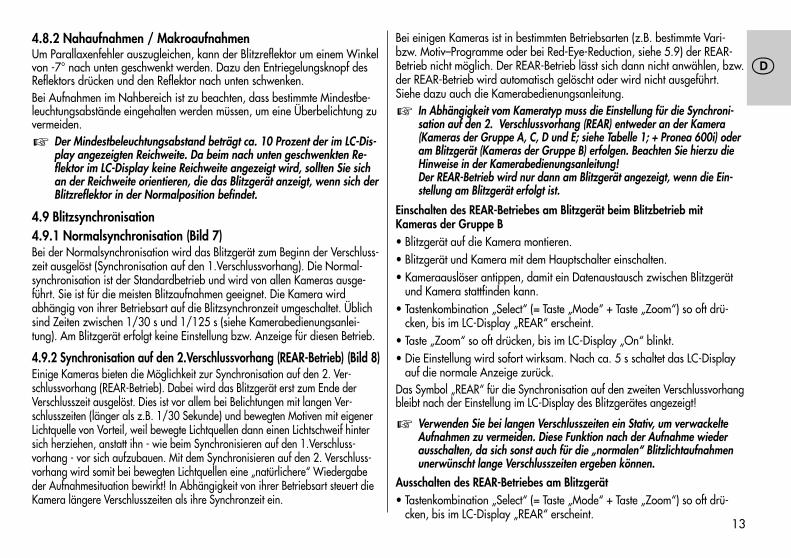
4.8.2 Nahaufnahmen / MakroaufnahmenUm Parallaxenfehler auszugleichen, kann der Blitzreflektor um einem Winkelvon -7° nach unten geschwenkt werden. Dazu den Entriegelungsknopf desReflektors drücken und den Reflektor nach unten schwenken.Bei Aufnahmen im Nahbereich ist zu beachten, dass bestimmte Mindestbe-leuchtungsabstände eingehalten werden müssen, um eine Überbelichtung zuvermeiden.
Der Mindestbeleuchtungsabstand beträgt ca. 10 Prozent der im LC-Dis-play angezeigten Reichweite. Da beim nach unten geschwenkten Re-flektor im LC-Display keine Reichweite angezeigt wird, sollten Sie sichan der Reichweite orientieren, die das Blitzgerät anzeigt, wenn sich derBlitzreflektor in der Normalposition befindet.
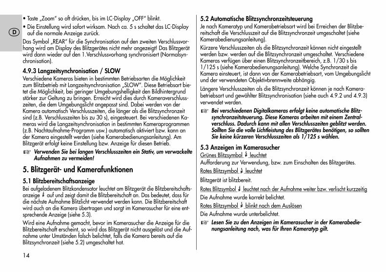
4.9 Blitzsynchronisation4.9.1 Normalsynchronisation (Bild 7)Bei der Normalsynchronisation wird das Blitzgerät zum Beginn der Verschluss-zeit ausgelöst (Synchronisation auf den 1.Verschlussvorhang). Die Normal-synchronisation ist der Standardbetrieb und wird von allen Kameras ausge-führt. Sie ist für die meisten Blitzaufnahmen geeignet. Die Kamera wirdabhängig von ihrer Betriebsart auf die Blitzsynchronzeit umgeschaltet. Üblichsind Zeiten zwischen 1/30 s und 1/125 s (siehe Kamerabedienungsanlei-tung). Am Blitzgerät erfolgt keine Einstellung bzw. Anzeige für diesen Betrieb.
4.9.2 Synchronisation auf den 2.Verschlussvorhang (REAR-Betrieb) (Bild 8)Einige Kameras bieten die Möglichkeit zur Synchronisation auf den 2. Ver-schlussvorhang (REAR-Betrieb). Dabei wird das Blitzgerät erst zum Ende derVerschlusszeit ausgelöst. Dies ist vor allem bei Belichtungen mit langen Ver-schlusszeiten (länger als z.B. 1/30 Sekunde) und bewegten Motiven mit eigenerLichtquelle von Vorteil, weil bewegte Lichtquellen dann einen Lichtschweif hintersich herziehen, anstatt ihn - wie beim Synchronisieren auf den 1.Verschluss-vorhang - vor sich aufzubauen. Mit dem Synchronisieren auf den 2. Verschluss-vorhang wird somit bei bewegten Lichtquellen eine „natürlichere“ Wiedergabeder Aufnahmesituation bewirkt! In Abhängigkeit von ihrer Betriebsart steuert dieKamera längere Verschlusszeiten als ihre Synchronzeit ein.
�
Bei einigen Kameras ist in bestimmten Betriebsarten (z.B. bestimmte Vari-bzw. Motiv–Programme oder bei Red-Eye-Reduction, siehe 5.9) der REAR-Betrieb nicht möglich. Der REAR-Betrieb lässt sich dann nicht anwählen, bzw.der REAR-Betrieb wird automatisch gelöscht oder wird nicht ausgeführt.Siehe dazu auch die Kamerabedienungsanleitung.
In Abhängigkeit vom Kameratyp muss die Einstellung für die Synchroni-sation auf den 2. Verschlussvorhang (REAR) entweder an der Kamera(Kameras der Gruppe A, C, D und E; siehe Tabelle 1; + Pronea 600i) oderam Blitzgerät (Kameras der Gruppe B) erfolgen. Beachten Sie hierzu dieHinweise in der Kamerabedienungsanleitung!Der REAR-Betrieb wird nur dann am Blitzgerät angezeigt, wenn die Ein-stellung am Blitzgerät erfolgt ist.
Einschalten des REAR-Betriebes am Blitzgerät beim Blitzbetrieb mitKameras der Gruppe B• Blitzgerät auf die Kamera montieren.• Blitzgerät und Kamera mit dem Hauptschalter einschalten.• Kameraauslöser antippen, damit ein Datenaustausch zwischen Blitzgerät
und Kamera stattfinden kann.• Tastenkombination „Select“ (= Taste „Mode“ + Taste „Zoom“) so oft drü-
cken, bis im LC-Display „REAR“ erscheint.• Taste „Zoom“ so oft drücken, bis im LC-Display „On“ blinkt.• Die Einstellung wird sofort wirksam. Nach ca. 5 s schaltet das LC-Display
auf die normale Anzeige zurück.Das Symbol „REAR“ für die Synchronisation auf den zweiten Verschlussvorhangbleibt nach der Einstellung im LC-Display des Blitzgerätes angezeigt!
Verwenden Sie bei langen Verschlusszeiten ein Stativ, um verwackelteAufnahmen zu vermeiden. Diese Funktion nach der Aufnahme wiederausschalten, da sich sonst auch für die „normalen“ Blitzlichtaufnahmenunerwünscht lange Verschlusszeiten ergeben können.
Ausschalten des REAR-Betriebes am Blitzgerät• Tastenkombination „Select“ (= Taste „Mode“ + Taste „Zoom“) so oft drü-
cken, bis im LC-Display „REAR“ erscheint.
�
�
13
�
• Taste „Zoom“ so oft drücken, bis im LC-Display „OFF“ blinkt.• Die Einstellung wird sofort wirksam. Nach ca. 5 s schaltet das LC-Display
auf die normale Anzeige zurück.Das Symbol „REAR“ für die Synchronisation auf den zweiten Verschlussvor-hang wird am Display des Blitzgerätes nicht mehr angezeigt! Das Blitzgerätwird dann wieder auf den 1.Verschlussvorhang synchronisiert (Normalsyn-chronisation).
4.9.3 Langzeitsynchronisation / SLOWVerschiedene Kameras bieten in bestimmten Betriebsarten die Möglichkeitzum Blitzbetrieb mit Langzeitsynchronisation „SLOW“. Diese Betriebsart bie-tet die Möglichkeit, bei geringer Umgebungshelligkeit den Bildhintergrundstärker zur Geltung zu bringen. Erreicht wird dies durch Kameraverschluss-zeiten, die dem Umgebungslicht angepasst sind. Dabei werden von derKamera automatisch Verschlusszeiten, die länger als die Blitzsynchronzeitsind (z.B. Verschlusszeiten bis zu 30 s), eingesteuert. Bei verschiedenen Ka-meras wird die Langzeitsynchronisation in bestimmten Kameraprogrammen(z.B. Nachtaufnahme-Programm usw.) automatisch aktiviert bzw. kann ander Kamera eingestellt werden (siehe Kamerabedienungsanleitung). AmBlitzgerät erfolgt keine Einstellung bzw. Anzeige für diesen Betrieb.
Verwenden Sie bei langen Verschlusszeiten ein Stativ, um verwackelteAufnahmen zu vermeiden!
5. Blitzgerät- und Kamerafunktionen5.1 BlitzbereitschaftsanzeigeBei aufgeladenem Blitzkondensator leuchtet am Blitzgerät die Blitzbereitschafts-anzeige auf und zeigt damit die Blitzbereitschaft an. Das bedeutet, dass fürdie nächste Aufnahme Blitzlicht verwendet werden kann. Die Blitzbereitschaftwird auch an die Kamera übertragen und sorgt im Kamerasucher für eine ent-sprechende Anzeige (siehe 5.3).Wird eine Aufnahme gemacht, bevor im Kamerasucher die Anzeige für dieBlitzbereitschaft erscheint, so wird das Blitzgerät nicht ausgelöst und die Auf-nahme unter Umständen falsch belichtet, falls die Kamera bereits auf dieBlitzsynchronzeit (siehe 5.2) umgeschaltet hat.
�
5.2 Automatische BlitzsynchronzeitsteuerungJe nach Kameratyp und Kamerabetriebsart wird bei Erreichen der Blitzbe-reitschaft die Verschlusszeit auf die Blitzsynchronzeit umgeschaltet (sieheKamerabedienungsanleitung).Kürzere Verschlusszeiten als die Blitzsynchronzeit können nicht eingestelltwerden bzw. werden auf die Blitzsynchronzeit umgeschaltet. VerschiedeneKameras verfügen über einen Blitzsynchronzeitbereich, z.B. 1/30 s bis1/125 s (siehe Kamerabedienungsanleitung). Welche Synchronzeit dieKamera einsteuert, ist dann von der Kamerabetriebsart, vom Umgebungslichtund der verwendeten Objektivbrennweite abhängig.Längere Verschlusszeiten als die Blitzsynchronzeit können je nach Kamera-betriebsart und gewählter Blitzsynchronisation (siehe auch 4.9.2 und 4.9.3)verwendet werden.
Bei verschiedenen Digitalkameras erfolgt keine automatische Blitz-synchronzeitsteuerung. Diese Kameras arbeiten mit einem Zentral-verschluss. Dadurch kann mit allen Verschlusszeiten geblitzt werden.Sollten Sie die volle Lichtleistung des Blitzgerätes benötigen, so solltenSie keine kürzeren Verschlusszeiten als 1/125 s wählen.
5.3 Anzeigen im KamerasucherGrünes Blitzsymbol leuchtetAufforderung zur Verwendung, bzw. zum Einschalten des Blitzgerätes.Rotes Blitzsymbol leuchtet
Blitzgerät ist blitzbereit.Rotes Blitzsymbol leuchtet nach der Aufnahme weiter bzw. verlischt kurzzeitigDie Aufnahme wurde korrekt belichtet.Rotes Blitzsymbol blinkt nach dem AuslösenDie Aufnahme wurde unterbelichtet.
Lesen Sie zu den Anzeigen im Kamerasucher in der Kamerabedie-nungsanleitung nach, was für Ihren Kameratyp gilt.
�
�
14
�
5.4 Anzeigen im LC-DisplayDie Nikon-Kameras der Gruppe B, C, D und E (siehe Tabelle 1) übertragendie Werte für ISO, Objektivbrennweite (mm) und Blende an das Blitzgerät.Dieses passt seine erforderlichen Einstellungen automatisch an. Es errechnetaus den Werten und seiner Leitzahl die maximale Reichweite des Blitzlichtes.Blitzbetriebsart, Reichweite, Blende und Zoomreflektor-Position werden imLC-Display das Blitzgerätes angezeigt.Wird das Blitzgerät betrieben, ohne dass es Daten von der Kamera erhaltenhat (z.B. wenn die Kamera ausgeschaltet ist oder mit einer Kamera derGruppe A betrieben wird), so wird nur die gewählte Blitzbetriebsart, dieReflektorposition und "M.Zoom" angezeigt. Die Anzeigen für Blende undReichweite erfolgen erst, wenn das Blitzgerät die erforderlichen Daten vonder Kamera erhalten hat.
Anzeigen für Auto Zoom, Blende und Reichweite erfolgen nur mit Ka-meras der Gruppe B, C, D und E (siehe Tabelle 1), wenn diese miteinem AF-Objektiv bzw. Objektiv mit CPU betrieben werden!
5.4.1 Reichweitenanzeige im TTL-BlitzbetriebIm LC-Display des Blitzgerätes wird der Wert für die maximale Reichweitedes Blitzlichtes angezeigt. Der angezeigte Wert bezieht sich auf einen Re-flexionsgrad von 25 % des Motivs, was für die meisten Aufnahmesituationenzutrifft. Starke Abweichungen des Reflexionsgrades, z.B. bei sehr stark odersehr schwach reflektierenden Objekten, können die Reichweite des Blitzge-rätes beeinflussen.Beachten Sie bei der Aufnahme die Reichweitenanzeige im LC-Display desBlitzgerätes. Das Motiv sollte sich im Bereich von etwa 40 % bis 70 % desangezeigten Wertes befinden. Damit wird der Elektronik genügend Spiel-raum zum Ausgleich gegeben. Der Mindestabstand zum Motiv sollte 10 %des angezeigten Wertes nicht unterschreiten, um Überbelichtungen zu ver-meiden! Die Anpassung an die jeweilige Aufnahmesituation kann durchÄndern der Objektivblende erreicht werden.
�
5.4.2 Reichweitenanzeige im manuellen Blitzbetrieb M bzw. MLoIm LC-Display des Blitzgerätes wird der Entfernungswert angezeigt, der füreine korrekte Blitzbelichtung des Motivs einzuhalten ist. Die Anpassung andie jeweilige Aufnahmesituation kann durch Ändern der Objektivblende unddurch Wahl zwischen voller Lichtleistung M und der Teillichtleistung MLo er-reicht werden (siehe 4.7).
5.4.3 Überschreitung des AnzeigebereichsDas Blitzgerätes kann Reichweiten bis maximal 199 m bzw. 199 ft anzei-gen. Bei hohen ISO-Werten (z.B. ISO 6400) und großen Blendenöffnungenkann der Anzeigebereich überschritten werden. Dies wird durch einen Pfeilbzw. Dreieck hinter dem Entfernungswert angezeigt.
5.4.4 Ausblendung der ReichweitenanzeigeWird der Reflektorkopf aus seiner Normalposition nach oben bzw. untenabgeschwenkt, erfolgt keine Entfernungsanzeige im LC-Display des Blitz-gerätes!
5.4.5 Error-Anzeige „FEE“ im LC-Display des BlitzgerätesBei verschiedenen Kameras bzw. Kamerabetriebsarten (z.B. Programm P, Vari-Programme, Blendenautomatik S) ist es erforderlich, den Blendenring am Ob-jektiv auf die maximale Blendenzahl einzustellen. Befindet sich der Blendenringnicht in der Position der maximalen Blendenzahl, so erfolgt im LC-Display desBlitzgerätes bzw. der Kamera eine Error-Anzeige „FEE“! Überprüfen Sie indiesem Fall die Kamera- bzw. Objektiveinstellungen (siehe Kamerabedie-nungsanleitung).
5.4.6 Leitzahlanzeige bei Objektiven ohne CPUObjektive ohne CPU (d.h. ohne elektronische Datenübertragung) übertragenkeine elektrischen Informationen über Brennweite und Blendeneinstellung andie Kameras. Wird ein solches Objektiv mit einer Kamera aus Gruppe B, C,D und E eingesetzt, so erhält das Blitzgerät von der Kamera nur Daten überISO. Die Position des Zoomreflektors muss von Hand eingestellt werden (sie-he 5.7.2).
15
�
16
�
Mit verschiedenen Kameras wird im LC-Display des Blitzgerätes in diesemFall an Stelle eines Entfernungswertes die Leitzahl für die aktuelle Einstellungangezeigt. Die maximale Blitzreichweite ergibt sich nun aus der Beziehung:
LeitzahlReichweite = —————
Blende
Beachten Sie die Hinweise zur Motiventfernung unter 5.5! Bei abge-schwenktem Blitzreflektor erfolgt keine Leitzahlanzeige!
5.4.7 Meter - Feet - Umschaltung (m - ft)Die Reichweitenanzeige im LC-Display des Blitzgerätes kann wahlweise inMeter (m) oder Feet (ft) erfolgen. Zum Wechsel der Anzeige verfahren Siewie nachfolgend beschrieben:• Blitzgerät mit dem Hauptschalter ausschalten.• Tastenkombination „Select“ (= Taste „Mode“ + Taste „Zoom“) gedrückt hal-
ten.• Blitzgerät mit dem Hauptschalter einschalten.• Tastenkombination „Select“ (= Taste „Mode“ + Taste „Zoom“) loslassen.• Die Entfernungsanzeige wechselt von m in ft, bzw. von ft in m.
5.5 Blitzreichweitenbestimmung mit LeitzahltabelleKameras aus Gruppe A übertragen keine Daten für ISO, Blende und Brenn-weite an das Blitzgerät. Es erfolgen im LC-Display des Blitzgerätes keine An-zeigen für Kamerablende und Blitzreichweite. In diesem Fall können Sie dieReichweite des Blitzlichtes mit Hilfe der Tabelle 2 im Anhang (siehe Kapi-tel 10) ermitteln.Es gilt folgende Beziehung:
LeitzahlReichweite = —————
Blende
�
Dies gilt nicht für die indirekte Blitzbelichtung, z.B. bei abgeschwenk-tem Blitzreflektor!
Beispiel:Sie verwenden ISO 100 und die Objektiv-Brennweite 50 mm. Aus derTabelle 2 im Anhang entnehmen Sie die für diese Kombination gültigeLeitzahl 34. An der Kamera bzw. dem Objektiv wählen Sie z.B. dieBlende 4. Mit der oben genannten Formel ermitteln Sie nun die Reichweitedes Blitzlichtes:
Leitzahl 34Reichweite = ———————= 8,5 m
Blende 4
Für den manuellen Blitzbetrieb M mit voller Lichtleistung bedeutet dies, dass sichdas Motiv in 8,5 m Entfernung befinden soll, damit es korrekt belichtet wird.Für den TTL-Blitzbetrieb bedeutet dies, dass sich das Motiv maximal in 8,5 mEntfernung befinden darf. Um jedoch der Elektronik der Blitzbelichtungsauto-matik in der Kamera genug Spielraum zur Lichtregelung zu bieten, sollte sichdas Motiv in einer Entfernung zwischen 40 % und 60 % der errechnetenReichweite befinden. In oben angeführtem Beispiel entspricht das einer Ent-fernung von 3,4 m bis 5,1 m zum Motiv. Für Nahaufnahmen ist zu beachten,dass eine Mindestentfernung von 10 % des errechneten Wertes eingehaltenwerden muss, um Überbelichtungen zu vermeiden. Im oben angeführten Bei-spiel beträgt die Mindestentfernung 10 % von 8,5 m = 0,85 m.
Beachten Sie, dass sich die Reichweite auf Motive mit einem Refle-xionsgrad von 25 % bezieht, was für die meisten Aufnahmesitua-tionen zutrifft. Starke Abweichungen des Refexionsgrades, z.B. beisehr stark oder sehr schwach reflektierenden Motiven, können dieReichweite des Blitzgerätes beeinflussen.
�
�
17
�
5.6 LC-Display-BeleuchtungBeim Drücken der Taste „Mode“ bzw. der Taste „Zoom“ wird für ca. 10 s dieLC-Display-Beleuchtung des Blitzgerätes aktiviert. Beim Auslösen eines Blitzeswird die LC-Display-Beleuchtung ausgeschaltet.
Bei der ersten Betätigung der genannten Tasten erfolgt keine Ände-rung der Einstellungen am Blitzgerät!
Wurde im TTL-Blitzbetrieb die Aufnahme korrekt belichtet, so wird währendder „o.k.“-Anzeige (siehe 4.5) die LC-Display-Beleuchtung aktiviert.
5.7 Motor-Zoom-ReflektorDer Reflektor des Blitzgerätes kann Objektivbrennweiten ab 24 mm ausleuch-ten.5.7.1 „Auto-Zoom“Wenn das Blitzgerät mit einer Kamera aus Gruppe B, C, D oder E und einemObjektiv mit CPU betrieben wird, passt sich seine Zoom-Reflektor-Positionautomatisch der Objektivbrennweite an. Nach dem Einschalten des Blitzge-rätes wird in dessen LC-Display „Auto Zoom“ und die aktuelle Reflektorpo-sition angezeigt.Die automatische Reflektoranpassung erfolgt für Objektivbrennweiten ab24 mm. Wird eine Brennweite von weniger als 24 mm eingesetzt, so blinktim LC-Display die Anzeige „24“ mm als Warnhinweis, dass die Aufnahmevom Blitzgerät an den Bildrändern nicht vollständig ausgeleuchtet werdenkann.
Für Objektive mit Brennweiten ab 20 mm kann eine Weitwinkelstreu-scheibe (Sonderzubehör, siehe Kapitel 7) verwendet werden. DerBlitzreflektor muss sich dabei in der Position 24 mm befinden.
5.7.2 Manueller Zoom-Betrieb „M. Zoom“Bei Kameras aus Gruppe A oder bei Einsatz eines Objektivs ohne CPU (z.B.Manuell-Fokus-Objektiv), muss die Zoom-Position des Blitzreflektors manuellan die Objektivbrennweite angepasst werden. Der Auto-Zoom-Betrieb ist indiesem Fall nicht möglich! Im LC-Display des Blitzgerätes wird „M.Zoom“ (fürmanuelle Zoomeinstellung) und die aktuelle Zoom-Position (mm) angezeigt.
�
�
• Durch wiederholtes Drücken der Taste „Zoom“ am Blitzgerät können nach-einander folgende Reflektor-Positionen angewählt werden:
24 mm - 28 mm - 35 mm - 50 mm - 70 mm - 85 mm - 105 mm.Es erfolgt kein Warnhinweis bei fehlerhafter Einstellung der Zoomreflektor-position!
Wenn Sie nicht immer die volle Leitzahl und Reichweite des Blitzge-rätes benötigen, können Sie die Zoomreflektor-Position auf der An-fangsbrennweite des Zoomobjektives belassen. Damit ist garantiert,dass die Bildränder immer vollständig ausgeleuchtet werden. Sie spa-ren sich damit die fortwährende Anpassung an die Objektivbrenn-weite.
Beispiel:Sie benutzen ein Zoomobjektiv mit einem Brennweitenbereich von 35 mm bis105 mm. In diesem Beispiel stellen Sie die Position des Zoomreflektors desBlitzgerätes auf 35 mm.
5.7.3 Manueller Zoom-Betrieb statt „Auto-Zoom“Auf Wunsch kann bei Kameras aus Gruppe B. C, D und E und Objektivenmit CPU die Position des Zoom-Reflektors manuell verstellt werden, um be-stimmte Beleuchtungseffekte zu erzielen (z.B. hot-spot usw.): Durch wieder-holtes Drücken der Taste „Zoom“ am Blitzgerät können nacheinander folgen-de Reflektor-Positionen angewählt werden:24 mm - 28 mm - 35 mm - 50 mm - 70 mm - 85 mm - 105 mm.Im LC-Display des Blitzgerätes wird „M.Zoom“ (für manuelle Zoomeinstel-lung) und die aktuelle Zoom-Position (mm) angezeigt. Die Einstellung wirdsofort wirksam. Nach ca. 5 s schaltet das LC-Display auf die normale An-zeige zurück.
Führt die manuelle Verstellung des Zoom-Reflektors dazu, dass dasBild an den Rändern nicht voll ausgeleuchtet werden kann, so blinktzur Warnung die Anzeige für die Reflektorposition auf dem Displaydes Blitzgerätes.
�
�
18
�
Beispiel:• Sie arbeiten mit Objektivbrennweite 50 mm.• Am Blitzgerät ist die Reflektorposition 70 mm von Hand eingestellt (An-
zeige „M.Zoom“).• Im LC-Display des Blitzgerätes blinkt die Anzeige „70“ mm für die Zoom-
position, weil die Bildränder nicht vollständig ausgeleuchtet werden können.Zurückstellen auf „Auto-Zoom“Zum Zurückstellen auf „Auto Zoom“ gibt es verschiedene Möglichkeiten:• Drücken Sie die Taste „Zoom“ am Blitzgerät so oft, bis im Display „Auto
Zoom“ angezeigt wird. Die Einstellung wird sofort wirksam. Nach ca. 5 sschaltet das LC-Display auf die normale Anzeige zurück.
Oder:• Schalten Sie das Blitzgerät mit dem Hauptschalter kurzzeitig aus. Nach
dem Wiedereinschalten wird im Display des Blitzgerätes „Auto Zoom“angezeigt.
5.7.4 Extended-Zoom-BetriebBeim Extended-Zoom-Betrieb (Ex) wird die Brennweite des Blitzgerätes umeine Stufe gegenüber der Objektiv-Brennweite der Kamera reduziert! Dieresultierende großflächigere Ausleuchtung sorgt in Räumen für zusätzlichesStreulicht (Reflexionen) und damit für eine weichere Blitzlicht-Ausleuchtung.Beispiel für den Extended-Zoom-Betrieb:Die Objektiv-Brennweite an der Kamera beträgt 35 mm. Im Extended-Zoom-Betrieb steuert das Blitzgerät auf die Reflektorposition 28 mm. Im LC–Displaywird jedoch weiterhin 35 mm angezeigt!Der Extended-Zoom-Betrieb ist nur in der Betriebsart "Auto Zoom" mit Kame-ras aus Gruppe B, C, D und E der Tabelle 1 und CPU-Objektiven mit Brenn-weiten ab 28 mm möglich.Da die Anfangsposition des Zoomreflektors 24 mm beträgt, wird bei Objek-tivbrennweiten von weniger als 28 mm im LC-Display "24" mm blinkend an-gezeigt. Dies ist ein Warnhinweis, dass eine für den Extended-Zoom-Betrieberforderliche Reflektorposition nicht angesteuert werden kann.
Aufnahmen mit Objektivbrennweiten von 24 mm werden auch im Ex-tended-Zoom-Betrieb vom Blitzgerät korrekt ausgeleuchtet!
Einschalten des Extended-Zoom-Betriebes• Tastenkombination „Select“ (= Taste „Mode“ + Taste „Zoom“) so oft drü-
cken, bis im LC-Display „Ex“ erscheint.• Taste „Zoom“ so oft drücken, bis im LC-Display „On“ blinkt.• Die Einstellung wird sofort wirksam. Nach ca. 5 s schaltet das LC-Display
auf die normale Anzeige zurück.Das Symbol „Ex“ für den Extended-Zoom-Betrieb bleibt nach der Einstellungim LC-Display des Blitzgerätes angezeigt!
Beachten Sie, dass sich durch die breitere Ausleuchtung im Extended-Zoom-Betrieb eine geringere Blitzreichweite ergibt!
Ausschalten des Extended-Zoom-Betriebes• Tastenkombination „Select“ (= Taste „Mode“ + Taste „Zoom“) so oft drü-
cken, bis im LC-Display „Ex“ erscheint.• Taste „Zoom“ so oft drücken, bis im LC-Display „Off“ blinkt.• Die Einstellung wird sofort wirksam. Nach ca. 5 s schaltet das LC-Display
auf die normale Anzeige zurück.Das Symbol „Ex“ für den Extended-Zoom-Betrieb wird nach dem Speichernim LC-Display des Blitzgerätes nicht mehr angezeigt!
5.8 Autofokus-MessblitzSobald die Umlichtverhältnisse für eine automatische Fokussierung nichtmehr ausreichen, wird von der Kameraelektronik der Autofokus-Messblitzaktiviert. Der Autofokusscheinwerfer strahlt dabei ein Streifenmuster ab, wel-ches auf das Motiv projiziert wird. Auf dieses Streifenmuster kann dann dieKamera automatisch fokussieren. Die Reichweite des AF-Messblitzes beträgtca. 6 m ... 9 m (bei Standardobjektiv 1,7/50 mm). Wegen der Parallaxezwischen Objektiv und AF-Rotlicht-Scheinwerfer beträgt die Naheinstell-grenze des Autofokus-Messblitzes ca. 0,7 m bis 1 m.
�
�
19
�
Damit der AF-Messblitz durch die Kamera aktiviert werden kann,muss an der Kamera die AF-Betriebsart „Single-AF (S)“ eingestellt sein(siehe Kamerabedienungsanleitung). Zoomobjektive mit geringer An-fangsblendenöffnung schränken die Reichweite des AF-Messblitzeszum Teil erheblich ein!Das Streifenmuster des AF-Messblitzes unterstützt nur den zentralenAF-Sensor der Kamera. Bei Kameras mit mehreren AF-Sensoren emp-fehlen wir nur das mittlere AF-Messfeld der Kamera zu aktivieren (sie-he Kamerabedienungsanleitung).Wenn der Fotograf manuell oder die Kamera selbstständig einendezentralen AF-Sensor auswählt, wird der Scheinwerfer für denAF–Messblitz des Blitzgerätes nicht aktiviert.Einige Kameras verwenden in diesem Fall den in die Kamera integriertenScheinwerfer für den AF-Messblitz (siehe Kamerabedienungsanleitung).
5.9 Vorblitze gegen den „Rote-Augen-Effekt“ (Red-Eye-Reduction)Beim „Rote-Augen-Effekt“ handelt es sich grundsätzlich um einen physikali-schen Effekt. Dieser Effekt tritt immer dann auf, wenn die zu fotografierendePerson mehr oder weniger voll in die Kamera blickt, das Umlicht relativ dun-kel ist und das Blitzgerät sich auf oder unmittelbar neben der Kamera befin-det. Das Blitzgerät hellt dabei den Augenhintergrund auf. Die blutgefüllteNetzhaut wird durch die Pupille hindurch sichtbar und von der Kamera alsroter Fleck oder Punkt aufgezeichnet.Die Funktion zur Verringerung des „Rote-Augen-Effektes“ (Red-Eye-Reduc-tion) bringt hier eine deutliche Verbesserung. Bei Verwendung dieser Funk-tion zündet das Blitzgerät vor dem Verschlussablauf drei sichtbare schwacheVorblitze, denen der Hauptblitz folgt. Diese Vorblitze führen dazu, dass sichdie Pupillen der Personen weiter schließen und damit den Effekt der rotenAugen verringern.Die Vorblitzfunktion wird an der Kamera eingestellt. Die aktivierte Vorblitz-Funktion wird am LC-Display der Kamera mit einem entsprechenden Symbolangezeigt (siehe Kamerabedienungsanleitung)! Am Blitzgerät erfolgt keineEinstellung bzw. Anzeige.
� Die Vorblitzfunktion zur Verringerung des „Rote-Augen-Effektes“ ist nur mitKameras möglich, welche diese Betriebsart unterstützen (siehe Kamerabedie-nungsanleiktung)!Bei einigen Kameras unterstützt die Red-Eye-Reduction nur das kamerainter-ne Blitzgerät bzw. einen extra Scheinwerfer im Kameragehäuse (siehe Be-dienungsanleitung der Kamera)!Bei Verwendung der Vorblitzfunktion ist die Synchronisation auf den 2. Ver-schlussvorhang (REAR) nicht möglich!
5.10 Automatikblitz / Zündungssteuerung (AUTO-FLASH)Ist das vorhandene Umgebungslicht für eine Belichtung im normalen Modusausreichend, so verhindern verschiedene Kameras die Blitzauslösung. BeimBetätigen des Kameraauslösers wird kein Blitzlicht ausgelöst.Die Zündungssteuerung arbeitet bei verschieden Kameras nur in derBetriebsart Vollprogramm oder Programm "P" bzw. muss an der Kameraaktiviert werden (siehe Kamerabedienungsanleitung).
5.11 Zurück zur GrundeinstellungDas Blitzgerät kann mit einem Tastendruck von mindestens drei Sekunden aufdie Taste „Mode“ zu seiner Grundeinstellung zurückgesetzt werden.Folgende Einstellungen werden gesetzt:• Blitzbetriebsart „TTL“.• Automatische Geräteabschaltung „Auto-Off“ wird aktiviert (3m On).• Automatischer Zoom-Betrieb „Auto-Zoom“.• Der Extended-Zoom-Betrieb „Ex“ wird gelöscht.• Blitzbelichtungskorrekturwert am Blitzgerät wird gelöscht.• REAR-Einstellung am Blitzgerät wird gelöscht.
20
�
6. Spezielle KamerahinweiseWegen der Vielzahl der Kameratypen und deren Eigenschaften ist es imRahmen dieser Bedienungsanleitung nicht möglich, auf alle kameraspezifi-schen Möglichkeiten, Einstellungen, Anzeigen usw. detailliert einzugehen.Informationen und Hinweise zum Einsatz eines Blitzgerätes entnehmen Siebitte den entsprechenden Kapiteln Ihrer Kamerabedienungsanleitung!
6.1 Im Blitzbetrieb nicht unterstützte Sonderfunktionen6.1.1 Programmverschiebung / Programm-ShiftMit eingeschaltetem Blitz ist bei verschiedenen Kameras die Programmver-schiebung (Zeit-Blenden-Paar) in der Programmautomatik P nicht durchführ-bar (siehe Kamerabedienungsanleitung).
7. SonderzubehörFür Fehlfunktionen und Schäden am Blitzgerät, verursacht durch dieVerwendung von Zubehör anderer Hersteller, wird keine Gewähr-leistung übernommen!
• Weitwinkelstreuscheibe 20 mm(Bestellnr. 000044217)Für die Ausleuchtung von Objektivbrennweiten ab 20 mm. Die Grenz-reichweiten verringern sich entsprechend dem Lichtverlust ca. um denFaktor 1,4.
• Farb-Filter-Set 44-32(Bestellnr. 00004432A)Umfasst 4 Farbfilter für Effektbeleuchtung und einen klaren Filter zur Auf-nahme von Farbfolien beliebiger Farbe.
• Mecabounce 44-90(Bestellnr. 000044900)Mit diesem Diffusor erreichen Sie auf einfachste Weise eine weiche Aus-leuchtung. Die Wirkung ist großartig, weil die Bilder einen softartigenEffekt erhalten. Die Gesichtsfarbe von Personen wird natürlicher wiederge-geben. Die Grenzreichweiten verringern sich entsprechend dem Lichtverlustcirca auf die Hälfte.
• Reflexschirm 54-23(Bestellnr. 000054236)Mildert durch sein weiches gerichtetes Licht harte Schlagschatten.
�
21
�
8. Hilfe bei StörungenSollte es einmal vorkommen, dass z.B. im LC-Display des Blitzgerätes unsin-nige Anzeigen erscheinen, oder das Blitzgerät funktioniert nicht so wie essoll, so schalten Sie das Blitzgerät für ca. 10 Sekunden mit dem Hauptschal-ter aus. Überprüfen Sie die korrekte Montage des Blitzgerätefußes im Zube-hörschuh der Kamera und die Kameraeinstellungen.Das Blitzgerät sollte nach dem Einschalten wieder „normal“ funktionieren. Istdies nicht der Fall, so wenden Sie sich bitte an Ihren Fachhändler.
9. Wartung und PflegeEntfernen Sie Schmutz und Staub mit einem weichen, trockenen oder silicon-behandelten Tuch. Verwenden Sie keine Reinigungsmittel - die Kunststoffteilekönnten beschädigt werden.
Formieren des Blitz-KondensatorsDer im Blitzgerät eingebaute Blitzkondensator erfährt eine physikalische Ver-änderung, wenn das Gerät längere Zeit nicht eingeschaltet wird. Aus diesemGrund ist es notwendig, das Gerät im vierteljährlichen Abstand für ca. 10 Min.einzuschalten (beachten Sie hierzu 2.4!). Die Batterien bzw. Akkus müssen da-bei so viel Energie liefern, dass die Blitzbereitschaft längstens 1 Min. nach demEinschalten aufleuchtet.
22
�
10. Technische DatenMax. Leitzahl bei ISO 100/21°; Zoom 105 mm:Im Metersystem: 44 Im Feet-System: 144Blitzleuchtzeiten:Ca. 1/200 ... 1/20.000 Sekunde (im TTL-Betrieb)Im M - Betrieb ca. 1/200 Sekunde bei voller LichtleistungIm MLo - Betrieb ca. 1/5000 SekundeFarbtemperatur:ca. 5600 KFilmempfindlichkeit:ISO 6 bis ISO 6400Synchronisation:NiederspannungszündungBlitzanzahlen:ca. 85 mit NC-Akku (600 mAh)ca. 205 mit NiMH-Akku (1600 mAh)ca. 240 mit Hochleistungs-Alkali-Mangan-Batterien
(bei jeweils voller Lichtleistung)Blitzfolgezeit:ca. 4 s mit NC-Akkuca. 4 s mit NiMH-Akkuca. 5 s mit Hochleistungs-Alkali-Mangan-Batterien
(bei jeweils voller Lichtleistung)Schwenkbereiche und Raststellungen des Reflektorkopfes:Nach oben / unten: 60°, 75°, 90° / -7°Abmaße ca. in mm:75 x 125 x 108 (B x H x T)
Gewicht:Blitzgerät mit Stromquellen: ca. 400 GrammAuslieferungsumfang:Blitzgerät, Bedienungsanleitung
Batterie-EntsorgungBatterien/Akkus gehören nicht in den Hausmüll! Bitte bedienen Sie sich beider Rückgabe verbrauchter Batterien/Akkus eines vorhandenen Rücknahme-systems.Bitte geben Sie nur entladene Batterien/Akkus ab. Batterien sind in der Regeldann entladen, wenn das damit betriebene Gerät- abschaltet und signalisiert „Batterien leer“- nach längerem Gebrauch der Batterien nicht mehr einwandfrei funktioniert.Zur Kurzschlusssicherheit sollten die Batteriepole mit einem Klebestreifenüberdeckt werden.Deutschland: Als Verbraucher sind Sie gesetzlich verpflichtet, gebrauchteBatterien zurückzugeben. Sie können Ihre alten Batterien überall dort unent-geltlich abgeben, wo die Batterien gekauft wurden. Ebenso bei den öffent-lichen Sammelstellen in Ihrer Stadt oder Gemeinde.Diese Zeichen finden Sie auf schadstoffhaltigen Batterien:Pb = Batterie enthält BleiCd = Batterie enthält CadmiumHg = Batterie enthält QuecksilberLi = Batterie enthält Lithium
Änderungen und Irrtümer vorbehalten !
23
�1. Die Garantiebestimmungen gelten ausschließlich für Käufe in der Bundes-
republik Deutschland ab 01.01.2002.2. Im Ausland gelten die Gewährleistungsregelungen des jeweiligen Landes
bzw. die Garantieregelungen des Verkäufers.3. Die nachfolgenden Bestimmungen haben nur für den privaten Gebrauch
Gültigkeit.4. Die Garantiezeit - 24 Monate - beginnt mit dem Abschluss des Kauf-
vertrages bzw. mit dem Tag der Auslieferung des Gerätes an den Käufer(Endverbraucher).
5. Garantieansprüche können nur unter Nachweis des Kaufdatums durchVorlage der Garantieurkunde und des vom Verkäufer maschinell erstelltenKaufbeleges geltend gemacht werden.
6. Beanstandete Geräte bitten wir zusammen mit dieser Garantieurkundeund dem Kaufbeleg entweder über den Fachhändler oder direkt an dieFirma Metz-Werke GmbH & Co KG - Zentralkundendienst - Ohmstrasse55, 90513 Zirndorf, transportsicher verpackt unter genauer Schilderungder Beanstandung einzusenden. Sie können unter den gleichenBedingungen auch an die autorisierten Kundendienststellen der FirmaMetz-Werke GmbH & Co KG eingesandt werden. Hin- und Rücksendungerfolgen auf Gefahr des Käufers.
7. Die Garantie besteht darin, dass Geräte, die infolge eines anerkanntenFabrikations- oder Materialfehlers defekt geworden sind, kostenlos repa-riert oder, soweit eine Reparatur unverhältnismäßig ist, ausgetauscht wer-den. Eine weitergehende Haftung, insbesondere für Schäden, die nicht amGerät selbst entstanden sind, ist ausgeschlossen. Dies gilt nicht, soweit imFalle des Vorsatzes oder der groben Fahrlässigkeit zwingend gehaftetwird. Garantieleistungen bewirken weder eine Verlängerung derGarantiezeit, noch wird für die ersetzten oder nachgebesserten Teile eineneue Garantiezeit begründet.
8. Unsachgemäße Behandlung und Eingriffe durch den Käufer oder Dritteschließen die Garantieverpflichtungen sowie alle weiteren Ansprüche aus.Ausgenommen von der Garantie sind ferner Schäden oder Fehler, diedurch Nichtbeachtung der Gebrauchsanleitung, mechanische Beschädi-gung, ausgelaufene Batterien oder durch höhere Gewalt, Wasser, Blitz etc.entstanden sind.Ferner sind Verschleiß, Verbrauch sowie übermäßige Nutzung von derGarantie ausgenommen. Hiervon sind vor allem folgende Teile betroffen:Blitzröhre, fest eingebaute Akkus, Kontakte, Verbindungskabel.
9. Durch diese Garantieurkunde werden die Gewährleistungsansprüche desKäufers gegenüber dem Verkäufer nicht berührt.
Metz-Werke GmbH & Co KG
GarantiebestimmungenBundesrepublik Deutschland
24
�
1. Consignes de sécurité . . . . . . . . . . . . . . . . . . . . . . . . . . . . . . . . 25Tableau 1. . . . . . . . . . . . . . . . . . . . . . . . . . . . . . . . . . . . . . . . . 26
2. Préparation du flash. . . . . . . . . . . . . . . . . . . . . . . . . . . . . . . . . 272.1 Montage du flash . . . . . . . . . . . . . . . . . . . . . . . . . . . . . . . . . . . 272.1.1 Fixation du flash sur l’appareil. . . . . . . . . . . . . . . . . . . . . . . . . . 272.1.2 Détacher le flash de l’appareil photo . . . . . . . . . . . . . . . . . . . . . 272.2 Alimentation. . . . . . . . . . . . . . . . . . . . . . . . . . . . . . . . . . . . . . . 272.2.1 Choix des piles ou accus . . . . . . . . . . . . . . . . . . . . . . . . . . . . . . 272.2.2 Remplacement des piles . . . . . . . . . . . . . . . . . . . . . . . . . . . . . . 272.3 Mise en marche et coupure du flash . . . . . . . . . . . . . . . . . . . . . . 272.4 Coupure automatique du flash / Auto - OFF. . . . . . . . . . . . . . . . 283. Automatisme programmé au flash (flash tout automatique) . . . . 284. Modes de fonctionnement du flash . . . . . . . . . . . . . . . . . . . . . . 294.1 Mode flash TTL . . . . . . . . . . . . . . . . . . . . . . . . . . . . . . . . . . . . . 294.1.1 Dosage automatique flash/ambiance en mode TTL . . . . . . . . . . . 294.1.2 Dosage flash/ambiance avec mesure matricielle TTL . . . . . . . . . . 304.1.3 Dosage automatique flash/ambiance par multi-capteur 3D . . . . . 304.2 Contrôle du flash D-TTL . . . . . . . . . . . . . . . . . . . . . . . . . . . . . . . 314.2.1 Contrôle du flash D-TTL 3D . . . . . . . . . . . . . . . . . . . . . . . . . . . . 314.3 Contrôle du flash i-TTL. . . . . . . . . . . . . . . . . . . . . . . . . . . . . . . . 314.3.1 Contrôle du flash i-TTL-BL . . . . . . . . . . . . . . . . . . . . . . . . . . . . . 324.4 Correction manuelle d’exposition au flash en mode TTL . . . . . . . . 324.5 Témoin de bonne exposition avec flash TTL . . . . . . . . . . . . . . . . . 334.6 Signalisation de sous-exposition au flash TTL. . . . . . . . . . . . . . . . 334.7 Mode flash manuel . . . . . . . . . . . . . . . . . . . . . . . . . . . . . . . . . . 344.7.1 Mode flash manuel M à pleine puissance lumineuse . . . . . . . . . . 344.7.2 Mode flash manuel MLo à puissance partielle . . . . . . . . . . . . . . . 344.8 Techniques de photographie au flash . . . . . . . . . . . . . . . . . . . . . 344.8.1 Eclairage indirect au flash . . . . . . . . . . . . . . . . . . . . . . . . . . . . . 344.8.2 Macrophotographie (photographie rapprochée) . . . . . . . . . . . . . 354.9 Synchronisation du flash . . . . . . . . . . . . . . . . . . . . . . . . . . . . . . 354.9.1 Synchronisation normale . . . . . . . . . . . . . . . . . . . . . . . . . . . . . . 354.9.2 Synchronisation sur le 2ème rideau (mode REAR). . . . . . . . . . . . . . 35
4.9.3 Synchronisation en vitesse lente / SLOW . . . . . . . . . . . . . . . . . . 365. Fonctions du flash et de l’appareil photo . . . . . . . . . . . . . . . . . . 365.1 Témoin de disponibilité du flash . . . . . . . . . . . . . . . . . . . . . . . . . 365.2 Commutation automatique sur la vitesse de synchro flash. . . . . . . 365.3 Signalisations dans le viseur . . . . . . . . . . . . . . . . . . . . . . . . . . . 375.4 Affichages sur l’écran de contrôle ACL . . . . . . . . . . . . . . . . . . . . 375.4.1 Affichage de portée en mode flash TTL . . . . . . . . . . . . . . . . . . . . 375.4.2 Affichage de portée en mode flash manuel M ou MLo . . . . . . . . . 375.4.3 Dépassement de la capacité d’affichage. . . . . . . . . . . . . . . . . . . 375.4.4 Suppression de l’affichage de portée . . . . . . . . . . . . . . . . . . . . . 375.4.5 Signalisation d’erreur „FEE“ sur l’écran ACL du flash. . . . . . . . . . 375.4.6 Affichage du nombre-guide avec un objectif à MAP manuelle . . . 385.4.7 Commutation mètres - feet (m - ft) . . . . . . . . . . . . . . . . . . . . . . . 385.5 Détermination de la portée de l’éclair avec le tableau du nombre-guide . 385.6 Eclairage de l’écran de contrôle ACL . . . . . . . . . . . . . . . . . . . . . 385.7 Asservissement de la tête zoom motorisée. . . . . . . . . . . . . . . . . . 395.7.1 „Auto-Zoom“ . . . . . . . . . . . . . . . . . . . . . . . . . . . . . . . . . . . . . . 395.7.2 Mode zoom manuel „M. Zoom“. . . . . . . . . . . . . . . . . . . . . . . . . 395.7.3 Mode zoom manuel au lieu de „Auto-Zoom“ . . . . . . . . . . . . . . . 395.7.4 Mode zoom étendu. . . . . . . . . . . . . . . . . . . . . . . . . . . . . . . . . . 405.8 Illuminateur AF . . . . . . . . . . . . . . . . . . . . . . . . . . . . . . . . . . . . . 405.9 Pré-éclairs réducteurs d’yeux rouges . . . . . . . . . . . . . . . . . . . . . 415.10 Flash automatique / Inhibition de l’éclair (AUTO-FLASH). . . . . . . 415.11 Retour aux réglages initiaux . . . . . . . . . . . . . . . . . . . . . . . . . . . 416. Conseils spécifiques concernant les reflex . . . . . . . . . . . . . . . . . 426.1 Fonctions spéciales non supportées par le flash . . . . . . . . . . . . . . 426.1.1 Décalage de programme / Programm-Shift . . . . . . . . . . . . . . . . 427. Accessoires en option . . . . . . . . . . . . . . . . . . . . . . . . . . . . . . . . 428. Remède en cas de mauvais fonctionnement. . . . . . . . . . . . . . . . 439. Entretien . . . . . . . . . . . . . . . . . . . . . . . . . . . . . . . . . . . . . . . . . 4310. Caractéristiques techniques. . . . . . . . . . . . . . . . . . . . . . . . . . . . 44
Tableau 2. . . . . . . . . . . . . . . . . . . . . . . . . . . . . . . . . . . . . . . . 134
�
�
25
�
Avant-proposNous vous remercions d’avoir porté votre choix sur un produit Metz et avonsle plaisir de vous saluer au sein de la grande famille de nos clients.Nous savons que vous brûlez d’envie d’essayer votre flash. Prenez tout demême le temps de lire le mode d’emploi. C’est la seule manière de découvrirles potentialités de votre flash et d’apprendre à les utiliser.Ce flash convient pour les appareils photo Nikon avec contrôle du flash TTL,D-TTL et i-TTL (i-TTL uniquement avec 44 AF-4i N). Le flash ne convient paspour les appareils d'autres marques !
Pour la lecture, dépliez le rabat en dernière page.
1. Consignes de sécurité• Le flash est conçu et agréé pour l’emploi exclusif en photographie.• Ne déclenchez en aucun cas un éclair à proximité de gaz ou de liquides
inflammables (essence, diluants, ...). RISQUE D’EXPLOSION !• Ne photographiez jamais au flash le conducteur d’un bus, d’un train,
d’une voiture, d’une moto ni un cycliste, car sous le coup de l’éblouisse-ment il risque de provoquer un accident.
• Ne déclenchez jamais le flash à proximité des yeux ! L’amorçage d’unéclair directement devant les yeux de personnes ou d’animaux peut en-traîner une lésion de la rétine et occasionner de graves troubles visuelspouvant aller jusqu’à l’aveuglement.
• Utilisez exclusivement les sources d’énergie autorisées mentionnées dansle mode d’emploi.
• N’exposez pas les piles ou accus à une trop grande chaleur, par ex. ausoleil, aux flammes ou autre.
• Ne jetez pas au feu les piles ni les accus usés !• Sortez immédiatement les piles usées du flash !
En effet, les piles usées peuvent „couler“ et provoquer une dégradationdu flash.
�
• Ne rechargez pas les piles sèches !• Maintenez votre flash et le chargeur à l’abri de l’eau tombant en gouttes
et des projections d’eau !• Ne soumettez pas le flash à une trop grande chaleur ni à une trop forte
humidité de l’air ! Ne conservez pas le flash dans la boîte à gants devotre voiture !
• Au moment de déclencher un éclair, il ne doit pas se trouver de matièreopaque directement devant ni sur la glace du réflecteur. La glace duréflecteur ne doit pas non plus être souillée. En cas de non-respect decette consigne de sécurité, l’énergie de l’éclair peut provoquer des brûlu-res sur la matière opaque ou sur la glace du réflecteur.
• Après une séquence d’éclairs, la glace du réflecteur est très chaude. Nela touchez pas, risque de brûlure !
• Ne pas démonter le flash ! DANGER HAUTE TENSION ! Le flash ne ren-ferme pas de pièces susceptibles de pouvoir être réparées par un non-spécialiste.
• Si vous êtes amené à faire des séries de photos au flash à pleine puis-sance en bénéficiant du recyclage rapide procuré par le fonctionnementsur accus NiCd, veillez à faire une pause d’au moins 10 minutes après15 éclairs pour éviter de surcharger le flash.
• Le flash ne peut être utilisé conjointement avec le flash intégré de l’ap-pareil photo que si celui-ci peut être complètement déployé !
• Un changement rapide de température peut entraîner la formation debuée. Laisser le temps à l’appareil pour s’acclimater !
• Ne pas utiliser des piles ou accus défectueux !
�
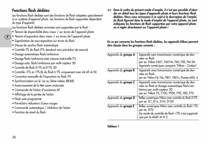
�
26
�
Fonctions flash dédiéesLes fonctions flash dédiées sont des fonctions de flash adaptées spécialementà un système d’appareil photo. Les fonctions de flash supportées dépendentdu type d’appareil.Les fonctions flash dédiées suivantes sont supportées par le flash :• Témoin de disponibilité dans viseur / sur écran de l’appareil photo• Témoin d’exposition dans viseur / sur écran de l’appareil photo• Signalisation de sous-exposition sur écran du flash• Vitesse de synchro flash automatique• Contrôle TTL du flash (TTL standard sans pré-éclair de mesure)• Dosage automatique flash/ambiance• Dosage flash/ambiance avec mesure matricielle TTL• Dosage auto. flash/ambiance par multi-capteur 3D• Contrôle de flash D-TTL et D-TTL-3D• Contrôle i-TTL et i-TTL-BL du flash (i-TTL uniquement avec 44 AF-4i N)• Correction manuelle de l’exposition au flash TTL• Synchronisation sur le 1er ou 2ème rideau (REAR)• Asservissement de la tête zoom motorisée• Commande de l’éclair d’assistance AF• Affichage de la portée de l’éclair• Flash auto programmé• Pré-éclairs réducteurs d’yeux rouges• Commande automatique / inhibition de l’éclair• Fonction de réveil du flash
Dans le cadre du présent mode d’emploi, il n’est pas possible d’abor-der en détail tous les types d’appareils photo et leurs fonctions flashdédiées. Nous vous renvoyons à ce sujet à la description de l’emploidu flash figurant dans le mode d’emploi de l’appareil photo, où sontindiquées les fonctions de flash supportées par votre appareil photoou à régler directement sur l’appareil photo !
En ce qui concerne les fonctions flash dédiées, les appareils Nikon peuventêtre classés dans les groupes suivants :
Appareils du groupe A Appareils sans transmission numérique de don-nées au flashpar ex. Nikon F601, F601M, F60, F50, FM-3AAppareils numériques compacts “Nikon - Coolpix”
Appareils du groupe B Appareils avec transmission numérique de don-nées au flashpar ex. Nikon F4, F4s, F801, F801s, Pronea 600i, 6
Appareils du groupe C Appareils avec transmission numérique de don-nées au flash et dosage automatique flash/am-biance par multi-capteur 3Dpar ex. Nikon F5, F100, F90X, F90, F80, F70
Appareils du groupe D Reflex numériques Nikon avec contrôle du flash D-TTLpar ex. D1, D1x, D1H, D100
Appareils du groupe E Reflex numériques Nikon avec contrôle du flash i-TTLpar ex. D70(Le mode de contrôle de flash i-TTL n'est supportéque par le 44AF-4i N !)
Tableau 1
�
27
�
2. Préparation du flash2.1 Montage du flash2.1.1 Fixation du flash sur l’appareil
Couper l’appareil photo et le flash avec l’interrupteur général !
• Tourner l’écrou moleté jusqu’en butée contre le flash. A présent, le piond’immobilisation dans le sabot est complètement éclipsé dans le boîtier.
• Engager le sabot du flash dans la griffe porte-accessoires de l’appareilphoto.
• Tourner l’écrou moleté jusqu’en butée contre le boîtier de l’appareil photopour bloquer le flash. Sur les reflex sans trou d’immobilisation, le pionmonté sur ressort reste éclipsé dans le boîtier du flash et n’abîme pas lasurface.
2.1.2 Détacher le flash de l’appareil photoCouper l’appareil photo et le flash avec l’interrupteur général.
• Tourner l’écrou moleté jusqu’en butée contre le flash.• Dégager le flash de la griffe porte-accessoires de l’appareil photo.
2.2 Alimentation2.2.1 Choix des piles ou accusLe flash peut fonctionner sur :• 4 accus NiCd 1,2 V, type IEC KR 15/51 (KR6 / AA / Mignon), ils pro-
curent des temps de recyclage très courts et sont économiques à l’usagecar rechargeables.
• 4 accus nickel-hydrure métallique 1,2 V, type HR6 (AA / Mignon), capaci-té nettement supérieure à celle des accus NiCd et moins nuisibles à l’envi-ronnement car sans cadmium.
• 4 piles alcalines au manganèse 1,5 V, type IEC LR6 (AA / Mignon),sources sans entretien pour exigences de performances moyennes.
�
�
• 4 piles au lithium 1,5 V, type FR6 L91 ;stockables sans perte de capacité pendant de nombreuses années, con-viennent donc très bien à l’utilisation sporadique.
Si le flash reste inutilisé pendant une longue période, sortez-en lespiles ou accus.
2.2.2 Remplacement des piles (Fig. 1)Les accus ou les piles sont vides ou usées lorsque le temps de recyclage (délaientre le déclenchement d’un éclair à pleine puissance, par ex. sur M, et l’in-stant d’allumage du témoin de disponibilité) dépasse les 60 secondes.• Couper le flash avec l’interrupteur général.• Repousser le couvercle du compartiment des piles dans le sens de la flèche
et le rabattre.• Introduire les piles ou les accus NiCd dans le sens de la longueur en vous
conformant aux symboles de piles puis refermer le couvercle.A la mise en place des piles ou accus, respecter la polarité (voir lessymboles de piles figurant dans le compartiment des piles). Une inver-sion de polarité peut conduire à la destruction de l’appareil ! Toujoursremplacer les piles et accus par jeu complet de piles/accus identiquesd’un même constructeur et de même capacité !Pensez à la protection de l’environnement ! Ne jetez pas les piles ouaccus à la poubelle, mais apportez-les à un point de collecte !
2.3 Mise en marche et coupure du flashLa mise en marche du flash s’effectue par l’interrupteur général sur le cou-vercle des piles. Sur la position supérieure „ON“, le flash est en service.Pour couper le flash, repousser l’interrupteur sur la position inférieure.
Si le flash reste inutilisé pendant une période prolongée, nous recom-mandons de couper le flash avec l’interrupteur général et de retirerles piles ou accus.
�
�
�
�
28
�
2.4 Coupure automatique du flash / Auto - OFF (Fig. 2)En usine, le flash est réglé pour se mettre en veille (Auto-OFF) 3 minutes envi-ron après• la mise en marche,• le déclenchement d’un éclair,• l’enfoncement à mi-course du déclencheur du reflex,• la coupure du système de mesure d’exposition du reflex...pour éviter une consommation inutile d’énergie et ménager ainsi les piles ouaccus. Le témoin de disponibilité et les affichages sur l’écran ACL du flashs’éteignent.Les réglages effectués avant la coupure automatique restent conservés et sontrétablis immédiatement à la remise en service. Le flash est réactivé en ap-puyant sur la touche „Mode“ ou „Zoom“ ou en enfonçant à mi-course le dé-clencheur de l’appareil photo (fonction de réveil).
Si le flash reste inutilisé pendant une période prolongée, il est conseil-lé de couper le flash avec l’interrupteur général !
Si on le désire, on peut désactiver la fonction de coupure automatique.Désactivation de la coupure automatique • Mettre en marche le flash avec l’interrupteur général.• Répéter l’appui sur la combinaison de touches „Select“ (= touche „Mode“ +
touche „Zoom“) jusqu’à ce que „3m“ (= 3 minutes) s’affiche sur l’écran ACL.• Répéter l’appui sur la touche „Zoom“ jusqu’à ce que „OFF“ clignote sur
l’écran ACL.• Le réglage prend effet immédiatement. Après env. 5 s, l’écran ACL retour-
ne à l’affichage normal.Activation de la coupure automatique• Mettre en marche le flash avec l’interrupteur général.• Répéter l’appui sur la combinaison de touches „Select“ (= touche „Mode“ +
touche „Zoom“) jusqu’à ce que „3m“ (= 3 minutes) s’affiche sur l’écran ACL.
�
• Répéter l’appui sur la touche „Zoom“ jusqu’à ce que „On“ clignote surl’écran ACL.
• Le réglage prend effet immédiatement. Après env. 5 s, l’écran ACL retour-ne à l’affichage normal.
3. Automatisme programmé au flash (flash tout automatique)Dans ce mode tout automatique, l’appareil photo gère l’ouverture, la vitessed’obturation et le flash de manière à obtenir un résultat optimal avec l’éclairdu flash, et ce dans la plupart des situations de prise de vue, aussi en fill-inau flash (dosage flash/ambiance).
Réglage sur l’appareil photoSélectionnez sur votre appareil le mode programme „P“ Vari, ou un pro-gramme-résultat (paysage, portait, sport etc.). Sur l’appareil photo, sélec-tionner le mode autofocus „Single-AF (S)“. Sur certains reflex Nikon (par ex.F5, F65, F80, F100), il faut toujours sélectionner sur l’objectif la plus grandeouverture possible (voir le mode d’emploi de l’appareil photo).
Avec un appareil du groupe A (voir Tableau 1) ou en liaison avec unobjectif sans CPU (c.-à-d. sans transmission électronique de données),adapter manuellement la position zoom du réflecteur à la distancefocale de l’objectif (voir 5.7.2) !
Dans le cas du programme „Prise de vue nocturne“, utiliser un tré-pied pour éviter le bougé dans le cas de longs temps de pose !
Réglages sur le flashUtilisation du flash avec des appareils des groupes A, B et C (voir Tableau 1) :Sélectionner sur le flash le mode “TTL” (voir chap. 4.1).En liaison avec des appareils du groupe B, on pourra au besoin activer sur leflash le dosage flash/ambiance avec mesure matricielle (voir 4.1.2).En liaison avec des appareils du groupe C, on pourra au besoin activer sur leflash le dosage automatique flash/ambiance par multi-capteur 3D (voir 4.1.3).
�
�
�
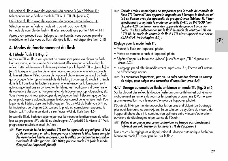
29
�
Utilisation du flash avec des appareils du groupe D (voir Tableau 1) :Sélectionner sur le flash le mode D-TTL ou D-TTL-3D (voir 4.2).Utilisation du flash avec des appareils du groupe E (voir Tableau 1) :Sélectionner sur le flash le mode i-TTL ou i-TTL-BL (voir 4.3).Le mode de contrôle de flash i-TTL n'est supporté que par le 44AF-4i N !Après avoir procédé aux réglages susmentionnés, vous pouvez prendreimmédiatement des vues au flash dès que le flash est disponible (voir 5.1)!
4. Modes de fonctionnement du flash4.1 Mode flash TTL (Fig. 3)La mesure TTL au flash vous permet de réussir sans peine vos photos au flash.Dans ce mode, la me-sure de l’exposition est effectuée par la cellule dans lereflex. Cette cellule mesure la lumière pénétrant par l’objectif (TTL = „Trough TheLens“). Lorsque la quantité de lumière nécessaire pour une lumination correctedu film est atteinte, l’électronique de l’appareil photo envoie un signal au flashqui provoque l’interruption immédiate de l’éclair. L’avantage du mode TTL résidedans le fait que tous les facteurs exerçant une influence sur la lumination sontautomatiquement pris en compte, tels les filtres, les modifications d’ouverture etde couverture des zooms, l’augmentation du tirage en macrophotographie, etc.Vous n’avez pas à vous préoccuper du réglage du flash, l’électronique de l’ap-pareil photo assure automatiquement le dosage correct de la lumière flash. Pourla portée de l’éclair, observez l’affichage sur l’écran ACL du flash (voir 5.4) oules indications du chapitre 5.5. Lorsque la photo est correctement exposée, letémoin „o.k.“ s’allume pendant 3 s sur l’écran ACL du flash (voir 4.5).Le contrôle TTL du flash est supporté par tous les modes de fonctionnement du reflex(par ex. programme „P“, priorité au diaphragme „A“, priorité à la vitesse „S“, Vari,programmes-résultats, manuel „M“, etc.).
Pour pouvoir tester la fonction TTL sur les appareils argentiques, il fautqu’ils contiennent un film. Lorsque vous choisirez le film, tenez comptedes éventuelles limites imposées par le reflex concernant la sensibilitémaximale du film (par ex. ISO 1000) pour le mode TTL (voir le moded’emploi de l’appareil photo)!
�
Certains reflex numériques ne supportent pas le mode de contrôle deflash TTL “normal” des appareils argentiques ! Lorsque le flash est uti-lisé en liaison avec des appareils du groupe D (voir Tableau 1), il fautsélectionner sur le flash le mode de contrôle D–TTL ou D-TTL-3D (voirchapitre 4.2). En liaison avec des appareils du groupe E (voir Ta-bleau 1) il faut sélectionner sur le flash le mode de contrôle i-TTL oui–TTL-BL. Le mode de contrôle de flash i-TTL n'est supporté que par le44AF-4i N. (voir chapitre 4.3) !
Réglage pour le mode flash TTL• Monter le flash sur l’appareil photo.• Mettre en marche le flash et l’appareil photo.• Répéter l’appui sur la touche „Mode“ jusqu’à ce que „TTL“ clignote sur
l’écran ACL.• Le réglage prend effet immédiatement. Après env. 5 s, l’écran ACL retour-
ne à l’affichage normal.Les contrastes importants, par ex. un sujet sombre devant un champde neige, peut exiger une correction d’exposition (voir 4.4).
4.1.1 Dosage automatique flash/ambiance en mode TTL (Fig. 5 et 6)Sur la plupart des reflex, le dosage flash/am-biance (fill-in) est activé auto-matiquement en lumière du jour sur les positions programme P, Vari et pro-grammes-résultats (voir le mode d’emploi de l’appareil photo).L’éclair de fill-in permet de déboucher les ombres et d’obtenir un éclairageplus équilibré dans les contre-jours. Le calculateur du système de mesure del’appareil photo choisit la combinaison optimale entre vitesse d’obturation,ouverture de diaphragme et puissance de l’éclair.
Veillez à ce que la source en contre-jour ne frappe pas directementl’objectif car cela fausserait la mesure TTL de l’appareil !
Dans ce cas, le réglage et la signalisation du dosage automatique flash/am-biance en mode TTL n’ont pas lieu sur le flash.
�
�
�
�
30
�
4.1.2 Dosage flash/ambiance avec mesure matricielle TTLDans ce mode de contrôle du flash, l’éclairage du sujet et de l’arrière-plan estautomatiquement équilibré, sans surexposition du sujet. Le réglage de l’exposi-tion pour la lumière ambiante est déterminé par l’appareil photo par mesurematricielle.Certains appareils Nikon supportent le dosage flash/ambiance avec mesurematricielle TTL (voir le mode d’emploi de l’appareil photo et Tableau 1).
Avec certains reflex (par ex. F4, F4s), le dosage automatique flash/ambiance par mesure matricielle TTL n’est pas supporté en mesured’exposition SPOT ! Ce mode de contrôle du flash est automatique-ment désactivé ou ne peut pas être activé. Le contrôle du flash s’effec-tue alors en mode TTL standard.
En liaison avec des appareils du groupe A (voir Tableau 1), le dosage flash/ambiance avec mesure matricielle TTL se règle sur l’appareil photo ou estactivé automatiquement (voir le mode d’emploi de l’appareil photo). Dans cecas, il n’y a ni réglage ni affichage sur le flash.En liaison avec des appareils du groupe B (voir Tableau 1), le réglage et l’affichagedu dosage flash/ambiance avec mesure matricielle TTL s’opèrent sur le flash :• Monter le flash sur l’appareil photo.• Mettre en marche le flash et l’appareil photo.• Enfoncer à mi-course le déclencheur de l’appareil photo pour provoquer
un échange de données entre l’appareil photo et le flash.• Répéter l’appui sur la touche „Mode“ jusqu’à ce que „TTL “ clignote sur
l’écran ACL.• Le réglage prend effet immédiatement. Après env. 5 s, l’écran ACL retourne à
l’affichage normal.Désactivation du dosage flash/ambiance avec mesure matricielle TTL• Répéter l’appui sur la touche “Mode” du flash jusqu’à ce que “TTL” (sans le
symbole ) clignote sur l’écran ACL.• Le réglage prend effet immédiatement. Après env. 5 s, l’écran ACL retourne à
l’affichage normal.
�
4.1.3 Dosage automatique flash/ambiance par multi-capteur 3DCe mode de contrôle du flash contribue à un éclairage équilibré du sujet et del’arrière-plan. Avant la prise de vue proprement dite, le flash émet une sériede pré-éclairs de mesure quasiment imperceptibles. Ces derniers sont évaluéspar le multi-capteur TTL et le microcontrôleur de l’appareil photo ; sur la basede ce calcul, l’appareil photo adapte de façon optimale l’exposition au flashTTL à la situation de prise de vue (dosage flash/ambiance par multi-capteur).En conjugaison avec des objectifs “AF Nikkor type D”, le calcul fait encoreintervenir la distance au sujet dans la détermination de la puissance optimalede l’éclair (dosage flash/ambiance par multi-capteur 3D).Certains appareils du groupe C selon Tableau 1 supportent le “dosageflash/ambiance par multi-capteur 3D”.
Avec certains reflex (par ex. F5, F80 et F100), le dosage automatiqueflash/ambiance par multi-capteur 3D n’est pas supporté en mesured’exposition SPOT ! Ce mode de contrôle du flash est automatique-ment désactivé ou ne peut pas être activé. Le contrôle du flash s’effec-tue alors en mode TTL standard.
Réglage pour le “dosage flash/ambiance par multi-capteur 3D” sur le flash• Monter le flash sur l’appareil photo.• Mettre en marche le flash et l’appareil photo.• Enfoncer à mi-course le déclencheur de l’appareil photo pour provoquer
un échange de données entre l’appareil photo et le flash.• Répéter l’appui sur la touche “Mode” jusqu’à ce que “TTL ” clignote sur
l’écran ACL.• Le réglage prend effet immédiatement. Après env. 5 s, l’écran ACL retourne à
l’affichage normal.Certains reflex, lorsqu’ils comportent un objectif sans CPU, ne supportentque le dosage flash/ambiance avec mesure matricielle ou que le modeflash TTL standard. Ils s’opposent à la sélection du dosage flash/am-biance par multi-capteur 3D. Le mode de contrôle du flash effectif estsignalé en conséquence sur l’écran ACL du flash.
�
�
�
31
�
Désactivation du “dosage flash/ambiance par multi-capteur 3D”• Répéter l’appui sur la touche “Mode” du flash jusqu’à ce que “TTL” (sans le
symbole ) clignote sur l’écran ACL.• Le réglage prend effet immédiatement. Après env. 5 s, l’écran ACL retourne à
l’affichage normal.
4.2 Contrôle du flash D-TTLCe mode de contrôle du flash n’est disponible qu’en liaison avec lesreflex numériques Nikon du groupe D (voir Tableau 1) ! Les reflex nu-mériques ne supportent pas le mode flash TTL standard des appareilsargentiques !
Le contrôle du flash D-TTL est une variante évoluée du contrôle de flash TTL“normal” des appareils argentiques. Avant la prise de vue proprement dite,le flash émet une série de pré-éclairs de mesure quasiment imperceptibles. Lalumière réfléchie des pré-éclairs est évaluée par l’appareil photo qui en dé-duit les paramètres de réglage optimaux du flash pour la prise de vue (voirle mode d’emploi de l’appareil photo).Procédure de réglage• Monter le flash sur l’appareil photo.• Mettre en marche le flash et l’appareil photo.• Enfoncer à mi-course le déclencheur de l’appareil photo pour provoquer
un échange de données entre l’appareil photo et le flash.• Répéter l’appui sur la touche “Mode” jusqu’à ce que “D TTL” clignote sur
l’écran ACL.• Le réglage prend effet immédiatement. Après env. 5 s, l’écran ACL retour-
ne à l’affichage normal.
4.2.1 Contrôle du flash D-TTL-3DDans ce mode avec contrôle du flash D-TTL (voir ci-dessus), l’appareil photoprend aussi en compte des informations de distance flash-sujet.
Ce mode de contrôle du flash n’est disponible qu’en liaison avec lesobjectifs “AF Nikkor type D”. Avec certains reflex, le mode flash
�
�
D–TTL 3D n’est pas supporté en mesure d’exposition SPOT ! Ce modede contrôle du flash est automatiquement désactivé ou ne peut pasêtre activé. Le contrôle du flash s’effectue alors en mode D-TTL nor-mal.
Pour pouvoir sélectionner le mode D-TTL 3D, le réflecteur du flash doit setrouver en position normale et ne doit pas être pivoté.Pour le mode D-TTL 3D, l’appareil photo et l’objectif doivent supporter l’éva-luation des informations de distance (voir le mode d’emploi de l’appareilphoto et les caractéristiques techniques de l’objectif) !Procédure de réglage• Monter le flash sur l’appareil photo.• Mettre en marche le flash et l’appareil photo.• Enfoncer à mi-course le déclencheur de l’appareil photo pour provoquer
un échange de données entre l’appareil photo et le flash.• Répétez l’appui sur la touche “MODE” sur le flash jusqu’à ce que “TTL” et
le symbole clignotent sur l’écran ACL.• Le réglage prend effet immédiatement et est mémorisé automatiquement
après 5 s.
4.3 Contrôle du flash i-TTLCe mode de contrôle du flash n'est disponible qu'avec les reflexnumériques Nikon du groupe E (voir tableau 1) en liaison avec lemecablitz 44 AF-4i N. Les reflex numériques ne supportent pas lemode flash TTL standard des appareils argentiques !
Le contrôle du flash i-TTL est une variante évoluée du contrôle de flash TTL“normal” des appareils argentiques. Avant la prise de vue proprement dite,le flash émet une série de pré-éclairs de mesure quasiment imperceptibles. Lalumière réfléchie des pré-éclairs est évaluée par l’appareil photo qui en dé-duit les paramètres de réglage optimaux du flash pour la prise de vue (voirle mode d’emploi de l’appareil photo).
�
�
32
�
Procédure de réglage• Monter le flash sur l’appareil photo.• Mettre en marche le flash et l’appareil photo.• Enfoncer à mi-course le déclencheur de l’appareil photo pour provoquer
un échange de données entre l’appareil photo et le flash.• Répéter l’appui sur la touche “Mode” jusqu’à ce que “TTL” clignote sur
l’écran ACL. Lors du fonctionnement en liaison avec un appareil photo dugroupe E le mode i-TTL est activé automatiquement sur le flash. Le symbole“i” n’est pas affiché.
• Le réglage prend effet immédiatement et est mémorisé automatiquementaprès 5 s.
4.3.1 Contrôle du flash i-TTL-BLDans ce mode avec contrôle du flash i-TTL (voir ci-dessus), l’appareil photoprend aussi en compte des informations de distance flash-sujet.
Ce mode de contrôle du flash n’est disponible qu’en liaison avec lesobjectifs “AF Nikkor type D”. Avec certains reflex, le mode flash i-TTL-BL n’est pas supporté en mesure d’exposition SPOT ! Ce mode de con-trôle du flash est automatiquement désactivé ou ne peut pas être acti-vé. Le contrôle du flash s’effectue alors en mode i-TTL normal.
Pour le mode i-TTL-BL, l’appareil photo et l’objectif doivent supporter l’éva-luation des informations de distance (voir le mode d’emploi de l’appareilphoto et les caractéristiques techniques de l’objectif) !En mesure SPOT, certains appareils photo ne supportent que le mode decontrôle i-TTL. Dans ce cas, il n’est pas possible d’activer le mode i-TTL BL !Procédure de réglage• Monter le flash sur l’appareil photo.• Mettre en marche le flash et l’appareil photo.• Enfoncer à mi-course le déclencheur de l’appareil photo pour provoquer
un échange de données entre l’appareil photo et le flash.
�
• Répétez l’appui sur la touche “MODE” sur le flash jusqu’à ce que “TTL” etle symbole clignotent sur l’écran ACL. Le symbole “i” n’est pas affiché.
• Le réglage prend effet immédiatement et est mémorisé automatiquementaprès 5 s.
4.4 Correction manuelle d’exposition au flash en mode TTLL’automatisme d’exposition TTL de la plupart des appareils photo est calibrépour une réflectance de 25 % (réflectance moyenne des sujets pris au flash). Lesfonds sombres qui absorbent beaucoup de lumière ou les fonds clairs très réflé-chissants (par ex. contre-jour) peuvent se traduire respectivement par une sous-exposition ou une surexposition.Pour rattraper l’erreur d’exposition mentionnée, certains appareils photo(voir Tableau 1) permettent de corriger l’exposition TTL (ou l’expositionD–TTL / l’exposition i-TTL avec les reflex numériques) manuellement d’unevaleur adaptée à la situation de prise de vue. La valeur de la correction dé-pend du contraste entre le sujet et le fond !
Sujet sombre sur fond clair : valeur de correction positive. Sujet clairsur fond sombre : valeur de correction négative. Le réglage d’une va-leur de correction peut entraîner la modification de la portée affichéesur l’écran ACL du flash et son adaptation à la valeur de correction(suivant le type d’appareil photo) !
Une correction d’exposition par action sur le diaphragme de l’objectif n’estpas possible puisque l’automatisme d’exposition de l’appareil photo consi-dérera l’ouverture corrigée comme ouverture de travail normale.
Après la photo, n’oubliez pas d’annuler à nouveau sur l’appareilphoto la correction d’exposition au flash TTL !
Suivant le type d’appareil photo, le réglage de la correction manuelled’exposition au flash en mode TTL doit se faire soit sur l’appareil photosoit sur le flash. Voyez à ce sujet les indications données dans le moded’emploi de l’appareil photo !Avec des appareils photo du groupe A (voir Tableau 1), le réglage s’opèretoujours sur l’appareil photo ! Le réglage sur le flash n’est pas possible !
�
�
�
�
33
�
Réglage sur le flash• Monter le flash sur l’appareil photo.• Mettre en marche le flash et l’appareil photo.• Enfoncer à mi-course le déclencheur de l’appareil photo pour provoquer
un échange de données entre l’appareil photo et le flash.• Répéter l’appui sur la combinaison de touches “Select” (= touche “Mode” +
touche “Zoom”) jusqu’à ce que EV (Exposure Value = indice de luminationIL) s’affiche sur l’écran ACL. EV est suivi de la valeur de correction réglée,qui s’affiche en clignotant.
• Tant que la valeur de correction clignote, les touches “Zoom” et “Mode”permettent respectivement de régler une valeur de correction positive etnégative.
La valeur de correction est réglable entre -3 EV (IL) et +1 EV (IL) par tiers devaleur.Le réglage prend effet immédiatement. Après env. 5 s, l’écran ACL retourne àl’affichage normal.Si le reflex est utilisé avec un objectif avec CPU, EV clignote à côté du sym-bole de diaphragme sur l’écran ACL du flash, pour signaler qu’une valeur decorrection manuelle est réglée pour l’exposition au flash.Si le reflex est utilisé avec un objectif sans CPU, l’écran ACL du flash affichepour EV la valeur de correction manuelle d’exposition au flash au lieu dusymbole de diaphragme et de l’ouverture du diaphragme. Au lieu de la por-tée de l’éclair, le flash affiche son nombre-guide actuel. On pourra alorsdéterminer la portée du flash en utilisant la formule donnée au chapitre 5.4.6.
Certains reflex offrent la possibilité de régler la valeur de correctionmanuelle directement sur le reflex même. Dans un tel cas, nous re-commandons de régler la valeur de correction soit sur le reflex soitsur le flash.
�
Annulation de la valeur de correction manuelle d’exposition au flash TTL surle flash• Répéter l’appui sur la combinaison de touches “Select” (= touche “Mode” +
touche “Zoom”) jusqu’à ce que EV s’affiche sur l’écran ACL.• La valeur de correction réglée clignote à côté de EV.• Tant que la valeur de correction clignote, les touches “Zoom” ou “Mode”
permettent d’annuler la valeur de correction en la réglant à 0.0.Le réglage prend effet immédiatement. Après env. 5 s, l’écran ACL retourneà l’affichage normal.
4.5 Témoin de bonne exposition avec flash TTL (Fig. 4)Le témoin de bonne exposition “o.k.” ne s’affiche sur l’écran ACL que si laprise de vue avec contrôle TTL du flash ou avec un mode de contrôle TTL évo-lué (par ex. 3D-TTL, D-TTL, D-TTL-3D, i-TTL, i-TTL-BL etc.) à été correctementexposée !Si le témoin de bonne exposition „o.k.“ ne s’allume pas après la prise de vue,c’est que la photo a été sous-exposée et il faut répéter la photo avec une plusgrande ouverture du diaphragme (plus petit indice d’ouverture, par ex. f/8 aulieu de f/11) ou en se rapprochant du sujet ou de la surface réfléchissante (enéclairage indirect). Observer l’indication de portée sur l’écran ACL du flash(voir 5.4.1) et les indications du chapitre 5.5.
Pour la signalisation de bonne exposition dans le viseur, voir aussi 5.3 !
4.6 Signalisation de sous-exposition au flash TTLDans certains modes (p. ex. „P“ et „A“), quelques appareils Nikon du grou-pe C, D et E (Tableau 1) signalent aussi la sous-exposition au flash en divi-sions de diaphragme (IL) sur l’écran ACL du flash (voir mode d’emploi del’appareil photo).Si après la prise de vue au flash, le témoin „ok“ ne s’allume pas sur le flashet si le témoin de bonne exposition clignote dans le viseur, l’écran ACL duflash affiche passagèrement la valeur de sous-exposition entre -0,3 IL à–3,0 IL par 1/3 IL.
�
�
34
�
Dans les cas limites, il se peut que le témoin „ok“ ne s’allume pas sur le flashmais que le symbole de l’éclair clignote dans le viseur. Dans ce cas, l’exposi-tion est tout de même correcte.
Pour que la sous-exposition puisse être signalée, il faut que le mode TTLou un mode de contrôle TTL évolué (par ex. 3D-TTL, D-TTL, D–TTL–3D, i-TTL,i-TTL-BL etc.) soit réglé sur le flash.
4.7 Mode flash manuelSélectionner sur l’appareil photo le mode Priorité au diaphragme „A“ ou lemode manuel „M“ ou „X“. Régler sur l’appareil photo l’ouverture et la vitessed’obturation (pour „M“) convenant à la situation de prise de vue (voir lemode d’emploi de l’appareil photo).
4.7.1 Mode flash manuel M à pleine puissance lumineuseDans ce mode, le flash émet toujours un éclair non dosé avec sa pleine puissan-ce lumineuse. L’adaptation à la situation de prise de vue s’effectue en jouant surle réglage de l’ouverture sur l’appareil photo. Avec des appareils du groupe C,D et E, l’écran ACL du flash affiche la distance flash-sujet à respecter pour obte-nir une photo correctement exposée au flash (voir aussi 5.4.2).Procédure de réglage pour le mode flash manuel M• Mettre en marche le flash avec l’interrupteur général.• Répéter l’appui sur la touche „Mode“ jusqu’à ce que „M“ clignote sur
l’écran ACL.• Le réglage prend effet immédiatement. Après env. 5 s, l’écran ACL re-
tourne à l’affichage normal.
4.7.2 Mode flash manuel MLo à puissance partielleDans ce mode, le flash émet toujours un éclair non dosé ayant la puissancepartielle réglée manuellement (Low). L’adaptation à la situation de prise devue s’effectue en jouant sur le réglage du niveau de puissance partielle ousur le réglage de l’ouverture sur l’appareil photo. L’écran ACL du flash af-fiche la distance flash-sujet à respecter pour obtenir une photo correctementexposée au flash (voir aussi 5.4.2).
�
Procédure de réglage pour le mode flash manuel MLo• Mettre en marche le flash avec l’interrupteur général.• Répéter l’appui sur la touche “Mode” jusqu’à ce que “MLo” clignote sur
l’écran ACL.• Le réglage prend effet immédiatement. Après env. 5s, l'écran ACL retourne
à l'affichage normal.
4.8 Techniques de photographie au flash4.8.1 Eclairage indirect au flashLes photos prises au flash direct sont presque toutes caractérisées par desombres portées souvent inesthétiques. Et sur une grande profondeur dechamp, les lois de la physique font que l’arrière-plan reste souvent dans lapénombre. Ces phénomènes pourront être évités par l’éclairage indirect quidonne une lumière diffuse pour un éclairage doux et régulier du sujet et del’arrière-plan. Le réflecteur est dirigé vers une surface réfléchissante (p. ex. leplafond ou les murs de la pièce).Le réflecteur du flash est orientable dans le sens vertical jusqu’à 90°. En positionde base, le réflecteur est verrouillé mécaniquement. Pour le déverrouiller, enfon-cer le bouton de déverrouillage.On veillera à basculer le réflecteur d’un angle suffisant dans le sens verticalpour empêcher que de la lumière directe ne vienne frapper le sujet. On bas-culera donc au moins jusqu’à la position de crantage à 60°. Les indicationsde distance disparaissent de l’écran ACL. La distance flash-sujet en passantpar le plafond est maintenant une grandeur inconnue.La lumière diffuse renvoyée par la surface réfléchissante donne un éclairagedoux du sujet. La surface réfléchissante devra être de teinte neutre pour éviterdes retours de couleurs, à moins que l’on recherche des effets de couleurs,auquel cas elle pourra avoir la teinte voulue. On évitera aussi les surfacesanguleuses (par ex. poutres au plafond) qui risquent de placer dans l’ombreune partie de la scène.
�
35
�
Notez que la portée du flash diminue fortement en éclairage indirect.Pour une pièce de hauteur normale, la portée maximale de l’éclairpeut être calculée par la formule approchée suivante :
nombre-guidePortée = ———————————————
distance d’éclairage x 2
4.8.2 Macrophotographie (photographie rapprochée)Pour compenser l’erreur de parallaxe, le réflecteur principal est orientablevers le bas d’un angle de -7°. Pour l’abaisser, appuyer sur le bouton de dé-verrouillage du réflecteur puis basculer ce dernier vers le bas.En macrophotographie, il faut veiller à respecter une certaine distance ausujet pour éviter une surexposition.
La distance d’éclairage minimale est d’environ 10 % de la portée affi-chée sur l’écran ACL du flash. Or, comme le flash n’affiche pas deportée lorsque le réflecteur est basculé vers le bas, on se basera sur laportée affichée par le flash lorsque le réflecteur se trouve en positionnormale.
4.9 Synchronisation du flash4.9.1 Synchronisation normale (Fig. 7)En synchronisation normale, le flash est déclenché au début du temps depose (synchronisation sur le 1er rideau). La synchronisation normale est lemode de fonctionnement standard et est effectuée par tous les reflex. Elleconvient pour la majorité des prises de vue au flash. Suivant le mode sélec-tionné, l’appareil photo est commuté sur la vitesse de synchro flash, en géné-ral comprise entre 1/30e s et 1/125e s (voir le mode d’emploi du reflex). Cemode de synchronisation n’exige pas de réglage sur le flash et n’y est passignalé de façon particulière.
4.9.2 Synchronisation sur le 2ème rideau (mode REAR) (Fig. 8)Certains appareils photo offrent la possibilité de synchroniser sur le 2èmerideau (mode REAR). Dans ce cas, l’éclair n’est déclenché que sur la fin dutemps de pose. La synchronisation sur le second rideau ne produit de l’effetque pour les prises de vue avec temps de pose long (supérieur à 1/30e de
�
� seconde) et pour des sujets animés portant une source lumineuse, car lasource lumineuse mobile laisse alors derrière elle une traînée, contrairementà ce qui est le cas pour la synchronisation sur le premier rideau où la “traî-née” précède la source lumineuse. La synchronisation sur le second rideaupermet donc de rendre avec naturel les sujets lumineux animés ! Suivant lemode sélectionnée sur l’appareil photo, celui-ci réglera un temps de poseplus long que celui correspondant à sa vitesse de synchro.Avec certains appareils, la fonction REAR n’est pas possible pour certains modesde fonctionnement (par ex. certains programmes-résultats ou en liaison avec lafonction de réduction des yeux rouges, voir 5.9). La sélection de la fonction REARn’est alors pas possible ou la fonction est automatiquement désélectionnée oun’est pas exécutée. Voir à ce sujet le mode d’emploi de l’appareil photo.
Suivant le type d’appareil phot, le réglage pour la synchronisation surle 2ème rideau (REAR) doit s’effectuer soit sur l’appareil photo (appa-reils du groupe A, C, D et E; voir Tableau 1; + Pronea 600i) ou sur leflash (appareils du groupe B). Voyez à ce sujet les indications donnéesdans le mode d’emploi de l’appareil photo !Le mode REAR n’est signalé que sur le flash que si son réglage a eulieu sur le flash.
Activation du mode REAR sur le flash en liaison avec un appareil du groupe B• Monter le flash sur l’appareil photo.• Mettre en marche le flash et l’appareil photo.• Enfoncer à mi-course le déclencheur de l’appareil photo pour provoquer
un échange de données entre l’appareil photo et le flash.• Répéter l’appui sur la combinaison de touches “Select” (= touche “Mode” +
touche “Zoom”) jusqu’à ce que “REAR” s’affiche sur l’écran ACL.• Répéter l’appui sur la touche “Zoom” jusqu’à ce que “On” clignote sur
l’écran ACL.• Le réglage prend effet immédiatement. Après env. 5 s, l’écran ACL retour-
ne à l’affichage normal.Le symbole “REAR” de synchronisation sur le second rideau reste affiché sur
�
�
36
�
l’écran ACL du flash après le réglage !Considérant les temps de pose relativement longs, montez votre ap-pareil sur un trépied pour éviter les bougés. Désactivez la fonctionlorsque vous n’en avez plus besoin, sans quoi les prises de vue “nor-males” au flash seraient également prises avec un temps de pose pro-longé.
Désactivation du mode REAR sur le flash• Répéter l’appui sur la combinaison de touches “Select” (= touche “Mode” +
touche “Zoom”) jusqu’à ce que “REAR” s’affiche sur l’écran ACL.• Répéter l’appui sur la touche “Zoom” jusqu’à ce que “OFF” clignote sur
l’écran ACL.• Le réglage prend effet immédiatement. Après env. 5 s, l’écran ACL retourne à
l’affichage normal.Le symbole “REAR” de synchronisation sur le second rideau disparaît del’écran ACL du flash ! Le flash est à nouveau synchronisé sur le 1er rideau(synchronisation normale).
4.9.3 Synchronisation en vitesse lente / SLOWDans certains modes de fonctionnement, certains appareils photos sont com-patibles avec une synchronisation du flash en vitesse lente. Ce mode de con-trôle permet une meilleure mise en valeur de l’arrière-plan en faible lumière.Cela s’obtient en adaptant la vitesse d’obturation au niveau de lumière am-biante, ce qui donne en règle générale des vitesses plus lente que la vitessede synchro-flash (par ex. temps de pose jusqu’à 30 s). Sur certains appareilsphotos, la synchronisation en vitesse lente est activée automatiquement danscertains modes (par ex. programme “nuit”, etc.) ou elle peut être réglée surl’appareil (voir le mode d’emploi de l’appareil photo). Ce mode n’exige pasde réglage sur le flash et n’y est pas signalé de façon particulière.
Pour les temps de pose longs, montez votre appareil sur un trépiedpour éviter les bougés !
�
�5. Fonctions du flash et de l’appareil photo5.1 Témoin de disponibilité du flashLorsque le condensateur du flash est chargé, le témoin de disponibilité s’allume sur le flash pour signaler que la prochaine photo peut être priseavec l’éclairage par le flash. La disponibilité du flash est aussi transmise àl’appareil photo et est signalée dans le viseur (voir 5.3).Si l’on prend la photo avant l’apparition du témoin de disponibilité, le flashn’est pas déclenché, ce qui peut conduire éventuellement à une sous-exposi-tion si l’appareil a déjà été réglé sur la vitesse de synchro-flash (voir 5.2).
5.2 Commutation automatique sur la vitesse de synchro flashSuivant le type d’appareil et le mode sélectionné, le recyclage du flash s’ac-compagne de la commutation automatique sur la vitesse de synchro-flash(voir le mode d’emploi de l’appareil photo).Il n’est pas possible de régler une vitesse plus rapide que la vitesse de syn-chro-flash de l’appareil photo ou alors elle est commutée automatiquementsur cette vitesse. Certains appareils disposent d’une plage de synchronisa-tion, par ex. entre 1/30e s et 1/125e s (voir le mode d’emploi du reflex). Lavitesse de synchronisation choisie par l’appareil dépend alors du modesélectionné sur l’appareil, du niveau de l’éclairage ambiant et de la distancefocale de l’objectif.Suivant le mode sélectionné sur l’appareil et le mode de synchronisation cho-isi pour le flash, il est possible de sélectionner une vitesse plus lente que lavitesse de synchro-flash (voir aussi 4.9.2 et 4.9.3).
Sur certains appareils photo numériques, il ne se produit pas de com-mutation automatique sur la vitesse de synchro-flash. Ces appareilsdisposent d’un obturateur focal et permettent d’opérer au flash àtoutes les vitesses d’obturation. Pour obtenir la pleine puissance lumi-neuse du flash, nous recommandons de régler sur l’appareil photoune vitesse d’obturation plus rapide que le 1/125 s.
�
�
37
�
5.3 Signalisations dans le viseurSymbole éclair vert alluméDemande d’utilisation ou de mise en marche du flash.Symbole éclair rouge alluméLe flash est prêt à l’utilisation.Symbole éclair rouge reste allumé après la prise de vue ou s’éteint passagère-mentLa photo a été correctement exposée.Symbole éclair rouge clignote après le déclenchementLa photo a été sous-exposée.
Reportez-vous au mode d’emploi de votre appareil photo pour con-naître la signification des signalisations dans le viseur.
5.4 Affichages sur l’écran de contrôle ACLLes reflex Nikon du groupe B, C, D et E (voir Tableau 1) transmettent au flashles valeurs de ISO, la distance focale de l’objectif (mm) et l’ouverture du dia-phragme. Le flash adapte automatiquement ses réglages. A partir des va-leurs transmises et de son nombre-guide, il calcule la portée maximale del’éclair. Le mode de fonctionnement du flash, la portée, le diaphragme et laposition de la tête zoom du flash sont affichés sur l’écran ACL du flash.Si le flash est utilisé sans qu’il reçoive de données du reflex (par ex. lorsquel’appareil photo est coupé ou qu’il fait partie des appareils du groupe A), seulsle mode de flash sélectionné, la position de la tête zoom et “M.Zoom” sontaffichés. L’ouverture du diaphragme et la portée ne sont affichées que lorsquele flash aura reçu les informations nécessaires du reflex.
Les affichages d’Auto Zoom, d’ouverture et de portée n’ont lieu quepour des appareils du groupe B, C, D et E (voir Tableau 1) si ceux-cisont équipés d’un objectif AF ou d’un objectif avec CPU.
5.4.1 Affichage de portée en mode flash TTLL’écran ACL du flash affiche la valeur de la portée maximale de l’éclair. Lavaleur affichée se rapporte à une réflectance de 25 % du sujet, ce qui est lecas dans la plupart des situations de prise de vue. Des écarts importants du
�
�
degré de réflectance, par ex. pour des objets très fortement ou très faible-ment réfléchissants, peuvent fausser le calcul de la portée.Lors de la prise de vue, observer l’indication de portée sur l’écran ACL du flash.Le sujet devrait se trouver dans la zone allant env. de 40 % à 70 % de la portéeaffichée pour laisser à l’électronique du reflex une latitude suffisante pour doserla lumière. Pour éviter les surexpositions, il ne faudrait pas se rapprocher dusujet à moins de 10 % de la valeur de portée affichée. L’adaptation à la situa-tion de prise de vue peut se faire en jouant sur l’ouverture de l’objectif.
5.4.2 Affichage de portée en mode flash manuel M ou MLoL’écran de contrôle ACL affiche la distance à respecter pour obtenir unephoto avec une exposition correcte du sujet. L’adaptation à la situation deprise de vue peut se faire en jouant sur l’ouverture de l’objectif et en choi-sissant entre la pleine puissance lumineuse M et la puissance partielle MLo(voir 4.7).
5.4.3 Dépassement de la capacité d’affichageLe flash peut afficher une portée maximale de 199 m ou 199 ft. Pour des valeursélevées de sensibilité ISO (par ex. ISO 6400) et de grandes ouvertures du dia-phragme, il peut arriver que la portée maximale affichable soit dépassée. Ceciest signalé par une flèche (triangle) derrière la valeur de portée affichée.
5.4.4 Suppression de l’affichage de portéeLa portée de l’éclair n’est pas affichée sur l’écran ACL du flash lorsque leréflecteur est basculé vers le haut ou le bas !
5.4.5 Signalisation d’erreur “FEE” sur l’écran ACL du flashSur certains appareils ou dans certains modes de fonctionnement de l’appareil(par ex. programme P, Vari, programmes-résultats, priorité à la vitesse S), ilfaut positionner la bague du diaphragme de l’objectif sur l’indice d’ouverturemaximal (= ouverture minimale). Si la bague du diaphragme n’est pas régléesur l’indice d’ouverture maximal, l’écran ACL du flash ou de l’appareil affichela signalisation d’erreur “FEE”. Dans ce cas, vérifier le réglage de l’appareil etde l’objectif (voir le mode d’emploi de l’appareil photo).
�
38
�
5.4.6 Affichage du nombre-guide avec un objectif à MAP manuelleLes objectifs sans CPU (c.-à-d. sans transmission électronique de données) netransmettent pas d’informations électriques concernant la distance focale ni l’ou-verture réglée sur l’appareil. Si on utilise un tel objectif sur un appareil photo dugroupe B, C, D et E, le flash ne reçoit du reflex que des informations au sujet del’ISO. La position du réflecteur zoom doit être adaptée à la main (voir 5.7.2).En liaison avec certains appareils, l’écran ACL du flash affiche dans ce cas àla place de la portée le nombre-guide pour les réglages momentanés. La por-tée maximale de l’éclair est donnée par la formule :
nombre-guidePortée = ——————————
diaphragme
Veuillez tenir compte des remarques sous 5.5 concernant la distanceau sujet. Si le réflecteur est pivoté, le nombre-guide n’est pas affiché !
5.4.7 Commutation mètres - feet (m - ft)La portée peut être affichée sur l’écran ACL du flash au choix en mètres (m)ou en pieds (feet = ft). Marche à suivre pour basculer de l’un à l’autre :• Couper le flash avec l’interrupteur général.• Maintenir enfoncée la combinaison de touches “Select” (= touche “Mode”
+ touche “Zoom”).• Mettre en marche le flash avec l’interrupteur général.• Relâcher la combinaison de touches “Select” (= touche “Mode” + touche
“Zoom”).• L’affichage de distance bascule de m sur ft ou de ft sur m.
5.5 Détermination de la portée de l’éclair avec le tableau du nombre-guideLes appareils du groupe A ne transmettent pas au flash d’informations con-cernant la sensibilité ISO, le diaphragme et la distance focale. L’ouvertureréglée sur l’appareil et la portée de l’éclair ne sont pas affichées sur l’écranACL du flash. Dans ce cas, vous pouvez déterminer la portée de l’éclair aumoyen du Tableau 2 donné en annexe (voir chap. 10).
�
On a la formule :
nombre-guidePortée = ——————————
diaphragme
Cette formule ne vaut pas pour l’éclairage indirect, par exemple lors-que le réflecteur du flash est pivoté !
Exemple :Vous utilisez 100 ISO et une distance focale de 50 mm. Sur Tableau 2 enannexe vous relevez pour cette combinaison le nombre-guide 34. Sur l’ap-pareil ou l’objectif, vous sélectionnez par ex. le diaphragme 4. La formuleprécitée vous permet alors de calculer la portée :
nombre-guide 34Portée = ———————————— = 8,5 m
diaphragme 4En flash manuel M à pleine puissance, cela signifie que le sujet doit se trou-ver à une distance de 8,5 m pour être correctement exposé.Avec contrôle TTL du flash, cela signifie que le sujet peut se trouver au maxi-mum à une distance de 8,5 m. Cependant, pour laisser à l’électronique d’ex-position du reflex une latitude suffisante pour doser la lumière, le sujet de-vrait se trouver dans la zone allant env. de 40 % à 60 % de la portéecalculée. Dans l’exemple susmentionné, ceci correspondrait à une distanceentre 3,4 m et 5,1 m au sujet. Pour éviter les surexpositions en photographierapprochée, il ne faudrait pas se rapprocher du sujet à moins de 10 % de lavaleur de portée calculée. Dans l’exemple précédent, la distance minimalede 10 % de 8,5 m = 0,85 m.
Notez que les indications de portée sont données pour des sujets avecune réflectance de 25 %, ce qui est le cas dans la plupart des situa-tions de prise de vue. Des valeurs de réflectance fortement diver-gentes, par ex. avec des sujets très fortement ou très faiblement réflé-chissants, peuvent influencer la portée du flash.
5.6 Eclairage de l’écran de contrôle ACLLe fait d’appuyer sur la touche “Mode” ou “Zoom” a pour effet d’activerpendant environ 10 s l’éclairage de l’écran ACL. L’éclairage de l’écran ACL
�
�
�
sera coupé immédiatement au déclenchement de l’éclair.Le premier actionnement des touches mentionnées n’entraîne pas demodification des réglages sur le flash !
Si la photo a été correctement exposée en mode flash TTL, l’éclairage del’écran ACL est allumé pour la durée d’allumage du témoin “o.k.” (voir 4.5).
5.7 Asservissement de la tête zoom motoriséeLe réflecteur du flash peut couvrir des focales à partir de 24 mm.
5.7.1 “Auto-Zoom”Si le flash est utilisé avec un appareil photo du groupe B, C, D ou E et un ob-jectif avec CPU, la tête zoom motorisée s’adapte automatiquement à cette dis-tance focale. Après la mise en marche du flash, la mention “Auto Zoom” et laposition momentanée du réflecteur sont affichées sur l’écran ACL du flash.L’asservissement automatique de la tête zoom motorisée a lieu pour desdistances focales à partir de respectivemement 24 mm. En présence d’unobjectif avec une distance focale de moins que 24 mm, la valeur “24” mmclignote sur l’écran ACL du flash à titre d’avertissement de vignettage, du faitque l’éclair ne peut pas couvrir toute la photo jusqu’aux bords.
Pour les objectifs de focale à partir de 20 mm, on pourra utiliser un dif-fuseur grand angle (options, voir chapitre 7). La tête zoom du flash doitalors se trouver sur la position 24 mm.
5.7.2 Mode zoom manuel “M. Zoom”Avec un appareil du groupe A ou en liaison avec un objectif sans CPU (parex. objectif à MAP manuelle), il faut adapter manuellement la position zoomdu réflecteur à la distance focale de l’objectif. Le mode Auto-Zoom n’est paspossible dans un tel cas ! L’écran ACL du flash affiche “M.Zoom” (pour zoommanuel) et la position momentanée de la tête zoom (mm).• En répétant l’appui sur la touche “Zoom” sur le flash, on peut choisir de
façon séquentielle parmi l’une des positions de réflecteur suivantes :24 mm - 28 mm - 35 mm - 50 mm - 70 mm - 85 mm - 105 mm.Le réglage erroné de la position du réflecteur ne donne pas lieu à une signa-lisation d’avertissement !
�
�Si vous n’avez pas toujours besoin de la pleine puissance et de lapleine portée du flash, vous pouvez laisser la tête zoom sur la posi-tion correspondant à la plus petite distance focale de l’objectif zoom.Vous avez ainsi la garantie que les bords de l’image seront toujourstotalement couverts par l’éclair. Vous vous épargnez ainsi une adap-tation permanente à la focale variable de l’objectif.
Exemple :Vous utilisez un zoom 35 - 105 mm. Dans ce cas, vous réglez la tête zoomdu flash sur 35 mm.
5.7.3 Mode zoom manuel au lieu de “Auto-Zoom”Avec des appareils du groupe B, C, D et E et des objectifs avec CPU, onpeut, si on le désire, modifier manuellement la position de la tête zoom, parex. pour obtenir des effets d’éclairage spéciaux tels que hot-spot, etc. En ré-pétant l’appui sur la touche “Zoom” sur le flash, on peut choisir de façon sé-quentielle parmi l’une des positions de réflecteur suivantes :24 mm - 28 mm - 35 mm - 50 mm - 70 mm - 85 mm - 105 mm.L’écran ACL du flash affiche “M.Zoom” (pour Zoom Manuel) et la positionmomentanée de la tête zoom (mm). Le réglage prend effet immédiatement.Après env. 5 s, l’écran ACL retourne à l’affichage normal.
Si la correction manuelle de position a pour effet d’entraîner un vig-nettage sur les bords de la photo, la valeur de position de la têtezoom clignote à titre d’avertissement sur l’écran ACL du flash.
Exemple :• Vous opérez avec un objectif de focale 50 mm.• La position de réflecteur 70 mm est réglée à la main sur le flash (affichage
“M.Zoom”).• La valeur de position zoom “70” mm clignote sur l’écran ACL du flash, car
avec ce réglage l’éclair ne couvre pas la photo jusque dans les coins.
�
�
39
��
40
�
Retour à “Auto-Zoom”On a les possibilités suivantes pour retourner à “Auto Zoom” :• Répéter l’appui sur la touche “Zoom” du flash jusqu’à ce que “Auto Zoom”
s’affiche sur l’écran ACL. Le réglage prend effet immédiatement. Aprèsenv. 5 s, l’écran ACL retourne à l’affichage normal.
Ou :• Couper passagèrement le flash avec l’interrupteur général. A la remise en
marche, l’écran ACL du flash affiche “Auto Zoom”.
5.7.4 Mode zoom étenduDans le mode zoom étendu (Ex), le réglage de la tête zoom du flash est dé-calé automatiquement d’un cran vers les grands angles par rapport à la fo-cale réglée sur l’objectif. L’élargissement du faisceau procure en intérieur da-vantage de lumière diffuse (réflexions) et adoucit ainsi l’éclairage au flash.
Exemple de mode zoom étendu :La focale de l’objectif monté sur le reflex est de 35 mm. En mode zoom éten-du, le flash positionne sa tête zoom sur 28 mm. L’écran de contrôle ACL con-tinue cependant d’afficher 35 mm !Le mode zoom étendu n’est possible qu’en mode “Auto Zoom” avec desappareils du groupe B, C, D et E du Tableau 1 et des objectifs à CPU defocale à partir de 28 mm.Etant donné que la position extrême de la tête zoom est 24 mm, l’utilisationd’objectifs de focale inférieure à 28 mm se traduira par l’affichage cligno-tant de “24” mm sur l’écran ACL. Il s’agit là d’un avertissement signalant quela position qui serait nécessaire pour la fonction de zoom étendu ne peut pasêtre réalisée par la tête zoom du flash.
Les prises de vues avec des objectifs de distance focale comprise entre 24 mmseront tout de même correctement exposées, même en mode zoom étendu !
Activation du mode zoom étendu• Répéter l’appui sur la combinaison de touches “Select” (= touche “Mode” +
touche “Zoom”) jusqu’à ce que “Ex” s’affiche sur l’écran ACL.
�
• Répéter l’appui sur la touche “Zoom” jusqu’à ce que “On” clignote surl’écran ACL.
• Le réglage prend effet immédiatement. Après env. 5 s, l’écran ACL retour-ne à l’affichage normal.
Le symbole “Ex” du mode zoom étendu reste affiché sur l’écran ACL du flashaprès le réglage !
Notez que l’élargissement du faisceau de l’éclair en mode zoom éten-du se traduit par une moindre portée de l’éclair !
Désactivation du mode zoom étendu• Répéter l’appui sur la combinaison de touches “Select” (= touche “Mode” +
touche “Zoom”) jusqu’à ce que “Ex” s’affiche sur l’écran ACL.• Répéter l’appui sur la touche “Zoom” jusqu’à ce que “Off” clignote sur
l’écran ACL.• Le réglage prend effet immédiatement. Après env. 5 s, l’écran ACL retour-
ne à l’affichage normal.Le symbole “Ex” du mode zoom étendu n’est plus affiché sur l’écran ACL duflash !
5.8 Illuminateur AFLorsque la lumière ambiante est insuffisante pour permettre une mise aupoint automatique, l’électronique de l’appareil photo active l’illuminateur AF.Celui-ci émet un réseau de bandes qu’il projette sur le sujet. Le système auto-focus de l’appareil photo utilise ces bandes pour réaliser la mise au pointautomatique. La portée de l’illuminateur AF est d’environ 6 m ... 9 m (pourun objectif standard f1,7/50 mm). En raison de l’erreur de parallaxe entrel’objectif et le faisceau de l’illuminateur AF, la limite de mise au point rappro-chée de l’illuminateur AF est d’env. 0,7 m à 1 m.
Afin que l’illuminateur AF puisse être activé par l’appareil photo, l’ob-jectif monté sur le reflex doit être réglé sur le mode autofocus “Single-AF (S)” (voir le mode d’emploi de l’appareil photo). Les objectif zoomspeu lumineux (petite ouverture maximale) peuvent réduire considéra-blement la portée de l’illuminateur AF !
�
��
Le réseau de bandes de l’illuminateur AF n’est capté que par le colli-mateur AF central du reflex. Sur les modèles à plusieurs collimateursAF nous recommandons de n’activer que le collimateur central (voir lemode d’emploi de l’appareil photo).Si vous sélectionnez manuellement ou que le reflex sélectionne delui–même un des collimateurs AF décentrés, l’illuminateur AF du flashne sera pas activé pour l’éclair de mesure.Certains reflex contournent cette situation et utilisent pour l’éclair demesure l’illuminateur AF intégré dans le reflex (voir le mode d’emploide l’appareil photo).
5.9 Pré-éclairs réducteurs d’yeux rougesLes yeux rouges sont un effet purement physiologique. Cet effet se présentetoujours lorsque la personne photographiée regarde plus ou moins directe-ment en direction de l’appareil photo, lorsque la lumière ambiante est faibleet que le flash est monté directement sur l’appareil photo ou à sa proximitédirecte. L’éclair vient alors frapper le fond des yeux, et la rétine, qui présenteune forte irrigation sanguine, devient visible à travers la pupille dilatée dufait de l’obscurité. C’est ce qui forme la tache rouge sur la pellicule.La fonction de réduction d’yeux rouges apporte une amélioration sensible.Elle consiste à déclencher, avant l’ouverture du premier rideau et avant leséclairs de mesure pour le multi-capteur, trois éclairs visibles de faible intensitéqui seront ensuite suivis de l’éclair principal. Les pré-éclairs ont pour objet deprovoquer un rétrécissement de la pupille au moment de l’éclair principal ;atténuant ainsi l’effet d’yeux rouges.La fonction de réduction d’yeux rouges est réglée sur l’appareil photo. Lors-qu’elle est activée, la fonction de réduction d’yeux rouges est signalée surl’écran ACL du flash par le symbole dédié (voir le mode d’emploi de l’appa-reil photo) ! Sur le flash, il n’y a ni réglage ni affichage.La fonction de réduction d’yeux rouges n’est possible qu’avec des appareilsqui supportent cette fonction (voir mode d’emploi de l’appareil photo) !Sur certains appareils, la fonction de réduction d’yeux rouges n’est suppor-tée que par le flash intégré ou un illuminateur spécial incorporé dans le boî-
tier du reflex (voir mode d’emploi de l’appareil photo) !On ne peut pas utiliser conjointement la fonction de réduction d’yeux rougeset la synchronisation sur le 2ème rideau (REAR) !
5.10 Flash automatique / Inhibition de l'éclair (AUTO-FLASH)Si la lumière ambiante est suffisante pour une exposition en mode normal,certains appareils empêchent le déclenchement de l'éclair. L'actionnement dudéclencheur de l'appareil photo ne déclenche pas d'éclair. Sur certainsappareils, l'inhibition de l'éclair ne fonctionne qu'en mode tout automatiqueou Programme "P" et doit être activé sur l'appareil photo (voir le mode d'em-ploi de l'appareil photo).
5.11 Retour aux réglages initiauxLe flash peut être réinitialisé sur ses réglages de base en maintenant pendantau moins 3 secondes l’appui sur la touche “Mode”.Les réglages suivants sont activés :• Mode flash “TTL”.• Activation de la coupure automatique “Auto-Off” (3m On).• Mode zoom automatique “Auto-Zoom”.• Le mode zoom étendu “Ex” est annulé.• La valeur de correction d’exposition au flash sur le flash est annulée.• La fonction REAR est désactivée sur le flash.
41
��
42
�
6. Conseils spécifiques concernant les reflexEn considération de la multitude de types de reflex et de leurs propriétés, iln’est pas possible dans le cadre de ce mode d’emploi de traiter en détail tousles réglages, affichages et autres possibilités spécifiques aux différents mo-dèles de reflex. Vous trouverez dans les chapitres correspondants du moded’emploi de votre appareil reflex les informations et conseils concernantl’emploi d’un flash !
6.1 Fonctions spéciales non supportées par le flash6.1.1 Décalage de programme / Programm-ShiftLorsque le flash est en marche, le décalage de programme (couple vitesse-ouverture) n’est pas réalisable en automatisme programmé P (voir le moded’emploi de l’appareil photo).
7. Accessoires en optionNous déclinons toute responsabilité pour le mauvais fonctionnementet l’endommagement du flash dus à l’utilisation d’accessoires d’autresconstructeurs !
• Diffuseur grand-angle 20mm(réf. 000044217)Pour la couverture de focales d’objectifs à partir de 20 mm. Les limites deportée sont réduites dans le rapport de la perte de lumière, soit environ dufacteur 1,4.
• Jeu de filtres colorés 44-32(réf. 00004432A)Comprend 4 filtres de couleur pour des effets d’éclairage et un filtre trans-parent pouvant recevoir des gélatines de toutes couleurs.
• Mecabounce 44-90(réf. 000044900)Ce diffuseur offre un moyen simple pour obtenir un éclairage doux. L’effetest sensationnel en raison de l’effet soyeux des photos. La teinte des vi-sages est rendue avec plus de naturel. Les limites de portée sont réduitesdans le rapport de la perte de lumière, soit environ de moitié.
• Ecran réfléchissant 54-23(réf. 000054236)Renvoie une lumière diffuse pour atténuer les ombres portées.
�
�
43
�
8. Remède en cas de mauvais fonctionnementS’il devait arriver que l’écran de contrôle ACL du flash affiche des valeursaberrantes ou que le flash ne fonctionne pas comme il le devrait dans les dif-férents modes, couper le flash pendant environ 10 secondes au moyen del’interrupteur général. Vérifier les réglages sur l’appareil photo et si le pieddu flash est engagé correctement dans la griffe porte-accessoires.Le flash devrait alors refonctionner normalement. Si ce n’est pas le cas,adressez-vous à votre revendeur.
9. EntretienEliminez la poussière et la saleté au moyen d’un chiffon doux, sec ou silico-né. N’utilisez pas de détergent sous risque d’endommager la matière plas-tique.
Formation du condensateur de flashSi le flash reste longtemps sans être mis sous tension, le condensateur deflash subit une modification physique. Pour éviter ce phénomène, il est néces-saire de mettre le flash en marche pendant 10 minutes env. à intervalles detrois mois environ (voir à ce propos 2.4!). La charge des piles ou accus doitêtre suffisante pour que le témoin de recyclage s’allume au plus tard 1 mi-nute après la mise en marche.
�
44
�
10. Caractéristiques techniquesNombre-guide maximal pour ISO 100 / 21° ; zoom 105 mm :en mètres : 44 en feet : 144
Durées de l’éclair :env. 1/200 ... 1/20.000 s (en mode TTL)en mode M env. 1/200 s à pleine puissanceen mode MLo env. 1/5000 s
Température de couleur :env. 5600 K
Sensibilité du film :ISO 6 à ISO 6400
Synchronisation:amorçage à très basse tension
Autonomie :env. 85 éclairs avec accus NiCd (600 mAh)env. 205 éclairs avec accus NiMH (1600 mAh)env. 240 éclairs avec piles alcalines HP au Mg
(à chaque fois à pleine puissance)
Temps de recyclage :env. 4 s avec accus NiCdenv. 4 s avec accus NiMHenv. 5 s avec piles alcalines hautes perf. au Mg
(à chaque fois à pleine puissance)
Orientation et crantages de la tête zoom :vers le haut / bas : 60°, 75°, 90° / -7°
Dimensions approx. en mm :75 x 125 x 108 (L x H x P)
Poids :flash avec piles/accus : env. 400 grammes
Fourniture :flash, mode d’emploi
Elimination des batteriesNe pas jeter les batteries dans les ordures ménagères.Veuillez rendre vos batteries usées là où elles sont éventuellement reprisesdans votre pays.Veillez à ne rendre que des batteries/accus déchargés.En règle générale, les batteries/accus sont déchargés lorsque l’appareilqu’elles alimentaient :- arrête de fonctionner et signale „batteries vides”- ne fonctionne plus très bien au bout d’une longue période d’utilisation des
batteries.Pour éviter les courts-circuits, il est recommandé de couvrir les pôles des bat-teries de ruban adhésif.
Sous réserve de modifications et d’erreus !

45
�
✍ ✍
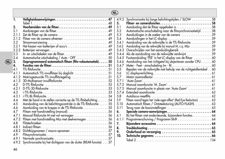
46
�
1. Veiligheidsaanwijzingen. . . . . . . . . . . . . . . . . . . . . . . . . . . . . . 47Tabel 1. . . . . . . . . . . . . . . . . . . . . . . . . . . . . . . . . . . . . . . . . . . 48
2. Voorbereiden van de flitser. . . . . . . . . . . . . . . . . . . . . . . . . . . . 492.1 Aanbrengen van de flitser . . . . . . . . . . . . . . . . . . . . . . . . . . . . . 492.1.1 Zet de flitser op de camera . . . . . . . . . . . . . . . . . . . . . . . . . . . . 492.1.2 Flitser van de camera afnemen . . . . . . . . . . . . . . . . . . . . . . . . . 492.2 Stroomvoorziening . . . . . . . . . . . . . . . . . . . . . . . . . . . . . . . . . . 492.2.1 Het kiezen van batterijen of accu’s . . . . . . . . . . . . . . . . . . . . . . . 492.2.2 Batterijen vervangen . . . . . . . . . . . . . . . . . . . . . . . . . . . . . . . . . 492.3 In- en uitschakelen van de flitser. . . . . . . . . . . . . . . . . . . . . . . . . 492.4 Automatische uitschakeling / Auto - OFF . . . . . . . . . . . . . . . . . . 503. Geprogrammeerd automatisch flitsen (flits-volautomatiek) . . . . . 504. Functies van de flitser . . . . . . . . . . . . . . . . . . . . . . . . . . . . . . . . 514.1 TTL-flitsfunctie . . . . . . . . . . . . . . . . . . . . . . . . . . . . . . . . . . . . . . 514.1.1 Automatisch TTL-invulflitsen bij daglicht . . . . . . . . . . . . . . . . . . . 514.1.2 Matrixgestuurde TTL-invulflitsregeling . . . . . . . . . . . . . . . . . . . . . 514.1.3 3D-Multisensor-invulflitsfunctie . . . . . . . . . . . . . . . . . . . . . . . . . . 524.2 D-TTL flitsfunctie . . . . . . . . . . . . . . . . . . . . . . . . . . . . . . . . . . . . 534.2.1 D-TTL-3D-flitsfunctie . . . . . . . . . . . . . . . . . . . . . . . . . . . . . . . . . 534.3 i-TTL-flitsfunctie . . . . . . . . . . . . . . . . . . . . . . . . . . . . . . . . . . . . . 534.3.1 i-TTL-BL-flitsfunctie. . . . . . . . . . . . . . . . . . . . . . . . . . . . . . . . . . . 544.4 Met de hand in te stellen correctie op de TTL-flitsbelichting . . . . . . 544.5 Aanduiding van de belichtingscontrole in de TTL-flitsfunctie . . . . . 554.6 Aanduiding van te krappe in de TTL-flitsfunctie . . . . . . . . . . . . . . 554.7 Flitsen met handinstelling (manual) . . . . . . . . . . . . . . . . . . . . . . . 564.7.1 Manual flitsfunctie M met vol vermogen . . . . . . . . . . . . . . . . . . . 564.7.2 Flitsen met handinstelling MLo met deelvermogen . . . . . . . . . . . . 564.8 Flitstechnieken . . . . . . . . . . . . . . . . . . . . . . . . . . . . . . . . . . . . . 564.8.1 Indirect flitsen . . . . . . . . . . . . . . . . . . . . . . . . . . . . . . . . . . . . . . 564.8.2 Dichtbijopnamen / macro-opnamen . . . . . . . . . . . . . . . . . . . . . 574.9 Flitssynchronisatie . . . . . . . . . . . . . . . . . . . . . . . . . . . . . . . . . . . 574.9.1 Normale synchronisatie. . . . . . . . . . . . . . . . . . . . . . . . . . . . . . . 574.9.2 Synchronisatie bij het dichtgaan van de sluiter (REAR-functie) . . . 57
4.9.3 Synchronisatie bij lange belichtingstijden / SLOW . . . . . . . . . . . 585. Flitser- en camerafuncties . . . . . . . . . . . . . . . . . . . . . . . . . . . . . 585.1 Aanduiding dat de flitser opgeladen is . . . . . . . . . . . . . . . . . . . . 585.2 Automatische omschakeling naar de flitssynchronisatietijd . . . . . . 585.3 Aanduidingen in de zoeker van de camera . . . . . . . . . . . . . . . . . 595.4 Aanduidingen in het LC-display . . . . . . . . . . . . . . . . . . . . . . . . . 595.4.1 Aanduiding van de reikwijdte in de TTL-flitsfunctie. . . . . . . . . . . . 595.4.2 Aanduiding van de reikwijdte bij manual M, c.q. MLo . . . . . . . . . . . . . 595.4.3 Overschrijden van het aanduidingbereik . . . . . . . . . . . . . . . . . . 595.4.4 Als de aanduiding van de reikwijdte verdwijnt . . . . . . . . . . . . . . 595.4.5 Foutaanduiding ‘FEE’ in het LC-display van de flitser . . . . . . . . . . 605.4.6 Aanduiding van het richtgetal bij objectieven zonder CPU . . . . . . 605.4.7 Meter - Feet - omschakeling (m - ft) . . . . . . . . . . . . . . . . . . . . . . 605.5 Bepalen van de reikwijdte met behulp van de richtgetallentabel . . 605.6 LC-displayverlichting . . . . . . . . . . . . . . . . . . . . . . . . . . . . . . . . . 615.7 Motor-zoomreflector . . . . . . . . . . . . . . . . . . . . . . . . . . . . . . . . . 615.7.1 ‘Auto-Zoom’. . . . . . . . . . . . . . . . . . . . . . . . . . . . . . . . . . . . . . . 615.7.2 Manual zoomfunctie ‘M. Zoom’ . . . . . . . . . . . . . . . . . . . . . . . . . 615.7.3 Manual zoomfunctie in plaats van ‘Auto-Zoom’ . . . . . . . . . . . . . 615.7.4 Extended-zoomfunctie . . . . . . . . . . . . . . . . . . . . . . . . . . . . . . . . 625.8 Autofocus-meetflits . . . . . . . . . . . . . . . . . . . . . . . . . . . . . . . . . . 625.9 Flitsen vooraf tegen het ‘rode-ogen-effect’ (Red-Eye-Reduction) . . . . . . . . 635.10 Automatisch flitsen / Ontsteeksturing (AUTO-FLASH). . . . . . . . . . 635.11 Terug naar de basisinstellingen . . . . . . . . . . . . . . . . . . . . . . . . . 636. Speciale camera-aanwijzingen . . . . . . . . . . . . . . . . . . . . . . . . . 646.1 Bij het flitsen niet ondersteunde, bijzondere functies. . . . . . . . . . . 646.1.1 Programverschuiving / Programm-Shift . . . . . . . . . . . . . . . . . . . 647. Bijzondere accessoires . . . . . . . . . . . . . . . . . . . . . . . . . . . . . . . 648. Troubleshooting . . . . . . . . . . . . . . . . . . . . . . . . . . . . . . . . . . . . 659. Onderhoud en verzorging . . . . . . . . . . . . . . . . . . . . . . . . . . . . 6510. Technische gegevens . . . . . . . . . . . . . . . . . . . . . . . . . . . . . . . . 66
Tabel 2. . . . . . . . . . . . . . . . . . . . . . . . . . . . . . . . . . . . . . . . . . 134
�
�
47
�
VoorwoordHartelijk dank voor uw beslissing een Metz product aan te schaffen. Wij ver-heugen ons u als klant te mogen begroeten.Natuurlijk kunt u nauwelijks wachten de flitser in gebruik te nemen. Het isechter lonend de gebruiksaanwijzing te lezen want alleen dan leert u omzonder problemen met het apparaat om te gaan. Deze flitser is geschikt voor Nikon- camera's met TTL-, D-TTL en i-TTL flitsre-gelingen (i-TTL alleen met de 44 AF-4i N). Op camera's van andere fabri-kanten kan de flitser niet worden gebruikt!
Voor camera’s van andere fabrikanten is deze flitser niet geschikt!
1. Veiligheidsaanwijzingen• De flitser is alleen bedoeld en toegelaten voor gebruik bij fotografische
toepassingen!• In de omgeving van ontvlambare gassen of vloeistoffen (benzine, oplos-
middelen enz.) mag in geen geval een flits worden ontstoken!GEVAAR VOOR EXPLOSIE!
• Auto-, bus- en treinbestuurders, berijders van fiets of motorfiets e.d. noo-it tijdens het rijden met flits fotograferen. Door de verblinding zou dezeeen ongeval kunnen veroorzaken!
• Ontsteek ook nooit een flits vlak bij de ogen! Een flits vlak bij de ogenvan personen of dieren zou beschadiging van het netvlies tot gevolgkunnen hebben en ernstige storingen bij het kijken kunnen veroorzaken,tot blindheid toe!
• Gebruik alleen de in de gebruiksaanwijzing aangegeven en toegelatenstroombronnen!
• Stel batterijen en accu’s niet bloot aan overmatige warmte zoals vanzonneschijn, vuur en dergelijke!
• Gooi verbruikte batterijen / accu’s niet in open vuur!
�
• Uit verbruikte batterijen kan loog lekken, dat tot beschadiging van decontacten leidt. Verbruikte batterijen daarom altijd uit het apparaatnemen.
• Batterijen kunnen niet worden opgeladen.• Stel de flitser en het oplaadapparaat niet bloot aan drup- of spatwater
(bijv. regen)!• Bescherm uw apparaat tegen grote hitte en hoge luchtvochtigheid!
Bewaar de flitser niet in het handschoenvak van uw auto!• Bij het ontsteken van een flits mag er zich geen licht-nietdoorlatend ma-
teriaal op of vlak voor het venster van de reflector bevinden. Het venstervan de reflector mag niet vuil zijn. Door de hoge energie van het flitslichtzou het materiaal of het venster van de reflector kunnen verbranden.
• Raak, na meervoudig flitsen het venster van de reflector niet aan.Gevaar voor verbranding!
• Neem de flitser niet uit elkaar! HOOGSPANNING!In het binnenst van de flitser bevinden zich geen onderdelen die dooreen leek zouden kunnen worden gerepareerd.
• Bij serieopnamen met vol vermogen en de korte flitsvolgtijden van deaccufunctie moet u er op letten, dat u telkens na 15 flitsen een pauze vanminstens 10 minuten aanhoudt, om overbelasting van het apparaat tevermijden.
• De flitser mag alleen dan samen met de in een camera ingebouwde flit-ser worden gebruikt, als deze laatste geheel kan worden opengeklapt!
• Bij snelle temperatuurwisseling kan het apparaat beslaan. Laat de flitserdan eerst acclimatiseren!
• Gebruik geen beschadigde batterijen of accu’s!
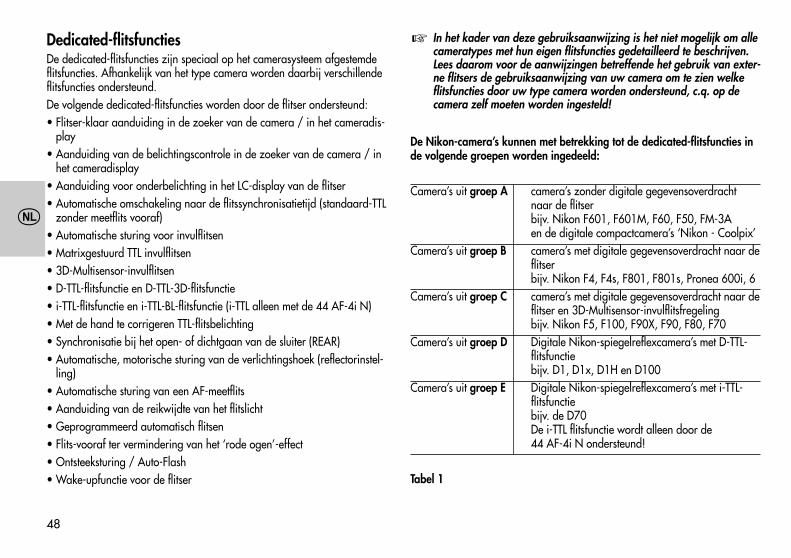
�
48
�
Dedicated-flitsfunctiesDe dedicated-flitsfuncties zijn speciaal op het camerasysteem afgestemdeflitsfuncties. Afhankelijk van het type camera worden daarbij verschillendeflitsfuncties ondersteund.De volgende dedicated-flitsfuncties worden door de flitser ondersteund:• Flitser-klaar aanduiding in de zoeker van de camera / in het cameradis-
play• Aanduiding van de belichtingscontrole in de zoeker van de camera / in
het cameradisplay• Aanduiding voor onderbelichting in het LC-display van de flitser• Automatische omschakeling naar de flitssynchronisatietijd (standaard-TTL
zonder meetflits vooraf)• Automatische sturing voor invulflitsen• Matrixgestuurd TTL invulflitsen• 3D-Multisensor-invulflitsen• D-TTL-flitsfunctie en D-TTL-3D-flitsfunctie• i-TTL-flitsfunctie en i-TTL-BL-flitsfunctie (i-TTL alleen met de 44 AF-4i N)• Met de hand te corrigeren TTL-flitsbelichting• Synchronisatie bij het open- of dichtgaan van de sluiter (REAR)• Automatische, motorische sturing van de verlichtingshoek (reflectorinstel-
ling)• Automatische sturing van een AF-meetflits• Aanduiding van de reikwijdte van het flitslicht• Geprogrammeerd automatisch flitsen• Flits-vooraf ter vermindering van het ‘rode ogen’-effect• Ontsteeksturing / Auto-Flash• Wake-upfunctie voor de flitser
In het kader van deze gebruiksaanwijzing is het niet mogelijk om allecameratypes met hun eigen flitsfuncties gedetailleerd te beschrijven.Lees daarom voor de aanwijzingen betreffende het gebruik van exter-ne flitsers de gebruiksaanwijzing van uw camera om te zien welkeflitsfuncties door uw type camera worden ondersteund, c.q. op decamera zelf moeten worden ingesteld!
De Nikon-camera’s kunnen met betrekking tot de dedicated-flitsfuncties inde volgende groepen worden ingedeeld:
Camera’s uit groep A camera’s zonder digitale gegevensoverdrachtnaar de flitserbijv. Nikon F601, F601M, F60, F50, FM-3Aen de digitale compactcamera’s ‘Nikon - Coolpix’
Camera’s uit groep B camera’s met digitale gegevensoverdracht naar deflitserbijv. Nikon F4, F4s, F801, F801s, Pronea 600i, 6
Camera’s uit groep C camera’s met digitale gegevensoverdracht naar deflitser en 3D-Multisensor-invulflitsfregelingbijv. Nikon F5, F100, F90X, F90, F80, F70
Camera’s uit groep D Digitale Nikon-spiegelreflexcamera’s met D-TTL-flitsfunctiebijv. D1, D1x, D1H en D100
Camera’s uit groep E Digitale Nikon-spiegelreflexcamera’s met i-TTL-flitsfunctiebijv. de D70De i-TTL flitsfunctie wordt alleen door de 44 AF-4i N ondersteund!
Tabel 1
�
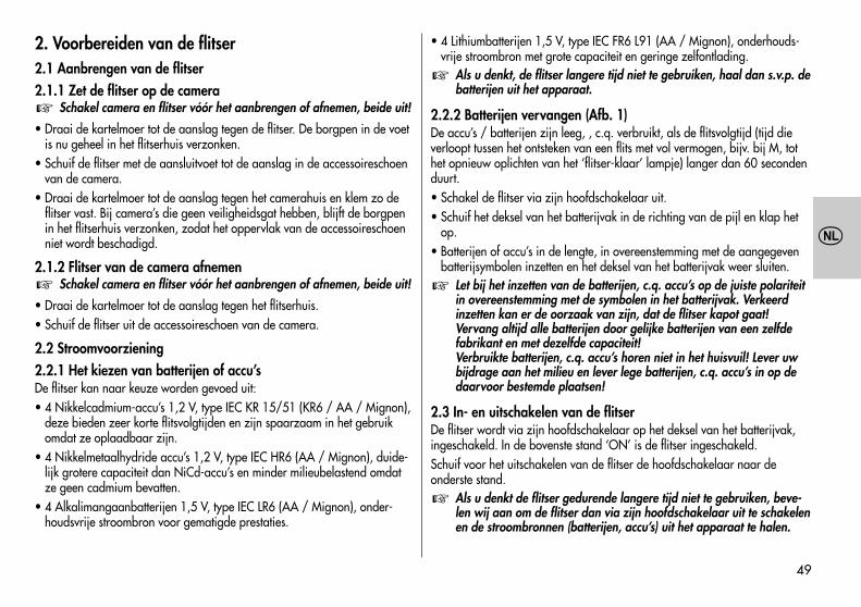
49
�
2. Voorbereiden van de flitser2.1 Aanbrengen van de flitser2.1.1 Zet de flitser op de camera
Schakel camera en flitser vóór het aanbrengen of afnemen, beide uit!
• Draai de kartelmoer tot de aanslag tegen de flitser. De borgpen in de voetis nu geheel in het flitserhuis verzonken.
• Schuif de flitser met de aansluitvoet tot de aanslag in de accessoireschoenvan de camera.
• Draai de kartelmoer tot de aanslag tegen het camerahuis en klem zo deflitser vast. Bij camera’s die geen veiligheidsgat hebben, blijft de borgpenin het flitserhuis verzonken, zodat het oppervlak van de accessoireschoenniet wordt beschadigd.
2.1.2 Flitser van de camera afnemenSchakel camera en flitser vóór het aanbrengen of afnemen, beide uit!
• Draai de kartelmoer tot de aanslag tegen het flitserhuis.• Schuif de flitser uit de accessoireschoen van de camera.
2.2 Stroomvoorziening2.2.1 Het kiezen van batterijen of accu’sDe flitser kan naar keuze worden gevoed uit:• 4 Nikkelcadmium-accu’s 1,2 V, type IEC KR 15/51 (KR6 / AA / Mignon),
deze bieden zeer korte flitsvolgtijden en zijn spaarzaam in het gebruikomdat ze oplaadbaar zijn.
• 4 Nikkelmetaalhydride accu’s 1,2 V, type IEC HR6 (AA / Mignon), duide-lijk grotere capaciteit dan NiCd-accu’s en minder milieubelastend omdatze geen cadmium bevatten.
• 4 Alkalimangaanbatterijen 1,5 V, type IEC LR6 (AA / Mignon), onder-houdsvrije stroombron voor gematigde prestaties.
�
�
• 4 Lithiumbatterijen 1,5 V, type IEC FR6 L91 (AA / Mignon), onderhouds-vrije stroombron met grote capaciteit en geringe zelfontlading.
Als u denkt, de flitser langere tijd niet te gebruiken, haal dan s.v.p. debatterijen uit het apparaat.
2.2.2 Batterijen vervangen (Afb. 1)De accu’s / batterijen zijn leeg, , c.q. verbruikt, als de flitsvolgtijd (tijd dieverloopt tussen het ontsteken van een flits met vol vermogen, bijv. bij M, tothet opnieuw oplichten van het ‘flitser-klaar’ lampje) langer dan 60 secondenduurt.• Schakel de flitser via zijn hoofdschakelaar uit.• Schuif het deksel van het batterijvak in de richting van de pijl en klap het
op.• Batterijen of accu’s in de lengte, in overeenstemming met de aangegeven
batterijsymbolen inzetten en het deksel van het batterijvak weer sluiten.Let bij het inzetten van de batterijen, c.q. accu’s op de juiste polariteitin overeenstemming met de symbolen in het batterijvak. Verkeerdinzetten kan er de oorzaak van zijn, dat de flitser kapot gaat!Vervang altijd alle batterijen door gelijke batterijen van een zelfdefabrikant en met dezelfde capaciteit!Verbruikte batterijen, c.q. accu’s horen niet in het huisvuil! Lever uwbijdrage aan het milieu en lever lege batterijen, c.q. accu’s in op dedaarvoor bestemde plaatsen!
2.3 In- en uitschakelen van de flitserDe flitser wordt via zijn hoofdschakelaar op het deksel van het batterijvak,ingeschakeld. In de bovenste stand ‘ON’ is de flitser ingeschakeld.Schuif voor het uitschakelen van de flitser de hoofdschakelaar naar deonderste stand.
Als u denkt de flitser gedurende langere tijd niet te gebruiken, beve-len wij aan om de flitser dan via zijn hoofdschakelaar uit te schakelenen de stroombronnen (batterijen, accu’s) uit het apparaat te halen.
�
�
�
50
�
2.4 Automatische uitschakeling / Auto – OFF (Afb. 2)In de fabriek is de flitser zo ingesteld, dat deze zich ong. 3 minuten –• na het inschakelen,• na het ontsteken van een flits,• na het aantippen van de ontspanknop op de camera,• na het uitschakelen van het belichtingsmeetsysteem in de camera ...... in de standby-functie schakelt (Auto-OFF) om energie te sparen en destroombronnen tegen voortijdig ontladen te beschermen. Het ‘flitser-klaar’lampje dooft en aanduidingen in het LC-display verdwijnen.De het laatst gebruikt instelling blijft na het automatisch uitschakelen behou-den en staat onmiddellijk na het weer inschakelen ter beschikking. De flitserwordt door op de toetsen ‘Mode’ of ‘Zoom’, c.q. door het aantippen van deontspanknop op de camera (Wake-upfunctie) weer ingeschakeld.
Als u de flitser gedurende een langere tijd niet gebruikt, schakel hemdan in principe altijd via de hoofdschakelaar uit!
Indien gewenst, kan de automatische uitschakeling uitgezet worden:Uitschakelen van de automatische uitschakeling• Schakel de flitser via zijn hoofdschakelaar in.• Druk zo vaak op de toetscombinatie ‘Select’ (= toets ‘Mode’ + toets ‘Zoom’),
dat in het LC-display ‘3 m’ (voor 3 minuten) wordt aangegeven.• Druk zo vaak op de toets ‘Zoom’, dat in het LC-display ‘OFF’ knippert.• De instelling treedt onmiddellijk in werking. Na ong. 5 s. schakelt het LC-dis-
play naar de normale weergave terug.Inschakelen van de automatische uitschakeling:• Schakel de flitser via zijn hoofdschakelaar in.• Druk zo vaak op de toetscombinatie ‘Select’ (= toets ‘Mode’ + toets ‘Zoom’),
dat in het LC-display ‘3 m’ (voor 3 minuten) wordt aangegeven.• Druk zo vaak op de toets ‘Zoom’, dat in het LC-display ‘On’ knippert.• De instelling treedt onmiddellijk in werking. Na ong. 5 s. schakelt het LC-dis-
play naar de normale weergave terug.
�
3. Geprogrammeerd automatisch flitsen (flits-volautomatiek)Bij het geprogrammeerd automatisch flitsen stuurt de camera diafragma,belichtingstijd en de flitser automatisch zodanig dat in de meeste gevallen,ook bij het invulflitsen, samen met het flitslicht een optimaal opnameresultaatwordt verkregen.Instellingen op de cameraZet uw camera in de functie Program ‘P’, of een Vari- , c.q. onderwerpspro-gramma (landschap, portret, sport enz.). Kies op de camera de autofocus-functie ‘Single-AF (S)’. Bij sommige Nikon-camera’s (bijv. F5, F65, F80 enF100) moet op het objectief steeds het hoogste diafragmagetal worden inge-steld (zie de gebruiksaanwijzing van de camera).
Bij een camera uit groep A (zie Tabel 1), c.q. bij het gebruik van eenobjectief zonder CPU (dus zonder elektronische gegevensoverdracht)de zoomstand van de flitsreflector met de hand instellen op de brand-puntsafstand van het objectief (zie 5.7.2)!
Gebruik bij het ‘nachtopnameprogramma’ een statief, om het gevaarvan camerabeweging bij het opnamen te vermijden om het gevaarvan camerabeweging tijdens het opnemen met de dan gebruikelijkelange belichtingen te vermijden!
Instellingen op de flitserFlitsen met camera’s uit de groepen A, B en C (zie Tabel 1):Stel op de flitser de functie ‘TTL’ in (zie hoofdstuk 4.1).Bij de camera’s uit groep B kan indien nodig bovendien de matrixgestuurdeinvulflitsfunctie op de flitser worden ingesteld (zie 4.1.2).Bij camera’s uit groep C kan indien nodige bovendien de 3D-Multisensor-invulflitsfunctie op de flitser worden ingesteld (zie 4.1.3).Flitsen met camera’s uit groep D (zie Tabel 1):Stel op de flitser de functie D-TTL, c.q. D-TTL-3D in (zie 4.2).Flitsen met camera’s uit groep E (zie Tabel 1):Stel op de flitser de functie i-TTL, c.q. i-TTL-BL in (zie 4.3).De i-TTL flitsfunctie wordt alleen door de 44 AF-4i N ondersteund!
�
�
51
�
Als u bovenstaande instellingen hebt uitgevoerd, kunt u met uw flitsopnamenbeginnen zodra de flitser aangeeft dat hij flitsklaar is (zie 5.1)!
4. Functies van de flitser4.1 TTL-flitsfunctie (Afb. 3)In de TTL-flitsfunctie krijgt u op een eenvoudige manier zeer goede flitsfoto’s.In deze flits wordt de belichtingsmeting door een sensor in de camera uitge-voerd. Deze meet in de camera de hoeveelheid door het objectief (TTL =’Through The Lens’) binnenvallende licht. Bals de voor een goede belichtingvereiste hoeveelheid licht is bereikt, zendt de elektronica in de camera eenstopsignaal naar de flitser en deze onderbreekt onmiddellijk het uitzendenvan flitslicht. Het voordeel van deze flitsfunctie ligt in het feit, dat alle factorendie de belichting kunnen beïnvloeden (opnamefilters, verandering van dia-fragmawaarde en brandpuntsafstand bij zoomobjectieven, uittrekverlengingvoor dichtbijopnamen enz.), automatisch bij de regeling van het flitslicht inacht worden genomen. U hoeft zich niet te bekommeren om de instelling vande flitser, de elektronica in de camera zorgt automatisch voor de juiste dose-ring van het flitslicht. Voor de reikwijdte van het flitslicht kijkt u op het LC-dis-play van de flitser (zie 5.4), c.q. de aanwijzingen in hoofdstuk 5.5. Bij eencorrect belichte flitsopname verschijnt gedurende ong. 3 s. in het LC-displayvan de flitser de ‘o.k.’-aanduiding (zie 4.5).De TTL-flitsfunctie wordt in alle camerafuncties (bijv. Program ‘P’, tijdautoma-tiek ‘A’, diafragma-automatiek ‘S’, Vari-, c.q. onderwerpsprogramma’s,Manual ‘M’ enz.) ondersteund.
Voor het testen van de TTL-functie moet zich bij analoge camera’s eenfilm in de camera bevinden! Let er, of er voor uw camera wellicht eenbeperking ten aanzien van de filmgevoeligheid, c.q. ISO-getal (bijv.maximaal ISO 1000) voor de TTL-flitsfunctie bestaat (zie de gebruiks-aanwijzing van de camera)!Sommige digitale SLR-camera’s ondersteunen de normale standaardTTL-flitsfunctie van analoge camera’s niet! Bij de flitsfunctie met came-ra’s uit groep D (zie Tabel 1) moet op de flitser de D-TTL, c.q. deD–TTL–3D-flitsfunctie worden ingesteld (zie hoofdstuk 4.2). Bij de flits-
�
functie met camera’s uit groep E (zie Tabel 1) moet op de flitser detitel, c.q. i-TTL-BL-flitsfunctie (i-TTL alleen met de 44 AF-4i N) wordeningesteld (zie hoofdstuk 4.3)!
Het instellen van de TTL-flitsfunctie• Breng de flitser aan op de camera.• Schakel flitser en camera in.• Druk zo vaak op de toets ‘Mode’, dat in het LC-display ‘TTL’ knippert.• De instelling treedt onmiddellijk in werking. Na ong. 5 s. schakelt het
LC–display naar de normale weergave terug.Bij sterke helderheidverschillen, bijv. donker onderwerp in de sneeuw,kan een correctie op de flitsbelichting noodzakelijk blijken (zie 4.4).
4.1.1 Automatisch TTL-invulflitsen bij daglicht (Afb. 5 en 6)Bij de meeste cameratypes wordt in de Programautomatiek P, en de Vari-,c.q. onderwerpsprogramma’s bij daglicht de automatische invulflitsfunctiegeactiveerd (zie de gebruiksaanwijzing van de camera).Met het invulflitsen kunt u lastige schaduwen wegwerken en bij tegenlichtop-namen een meer uitgebalanceerde belichting tussen onderwerp en achter-grond bereiken. Een computergestuurd meetsysteem in de camera zorgt vooreen geschikte combinatie van belichtingstijd, werkdiafragma en flitsvermo-gen.
Let er op, dat de bron van het tegenlicht niet rechtstreeks in het objec-tief schijnt. Het TTL-meetsysteem van de camera zou erdoor kunnenworden misleid!
Een instelling of aanduiding voor de automatische TTL-invulflitsfunctie ver-schijnt niet op de flitser en hoeft er niet op te worden ingesteld.
4.1.2 Matrixgestuurde TTL-invulflitsregelingIn deze flitsfunctie worden onderwerp- en achtergrondbelichting automatischop elkaar afgestemd, zonder dat het onderwerp zelf overbelicht wordt. Debelichtingsinstelling voor het omgevingslicht wordt door de camera via dematrixmeting bepaald.
�
�
52
�
Verschillende Nikon-camera’s ondersteunen de matrixgestuurde TTL-invulflits-functie (zie de gebruiksaanwijzing van de camera en Tabel 1).
Bij enkele camera’s (bijv. F4 en F4s) wordt de matrixgestuurde TTL-in-vulflitsfunctie bij SPOT-belichtingsmeting niet ondersteund! Deze flits-functie wordt bij die camera’s automatisch uitgeschakeld, c.q. is niette activeren. Daar wordt dan de normale TTL-flitsfunctie uitgevoerd.
Met camera’s uit groep A (zie Tabel 1) vindt de instelling van de matrixge-stuurde TTL-invulflitsfunctie op de camera, c.q. wordt deze door de cameraautomatisch geactiveerd (zie de gebruiksaanwijzing van de camera). Op deflitser hoeft in dit geval niets te worden ingesteld.Bij het gebruik met camera’s uit groep B (zie Tabel 1) vindt instelling en aan-duiding van de matrixgestuurde TTL-invulflitsfunctie plaats op de flitser:• Breng de flitser aan op de camera.• Schakel flitser en camera in.• Tip de ontspanknop op de camera aan, zodat er een uitwisseling van ge-
gevens tussen camera en flitser kan plaatsvinden.• Druk zo vaak op de toets ‘Mode’, dat in het LC-display ‘TTL ’ knippert.• De instelling treedt onmiddellijk in werking. De instelling treedt onmiddellijk
in werking. Na ong. 5 s. schakelt het LC-display weer naar de normaleweergave terug.
Uitschakelen van de ‘matrixgestuurde TTL-invulflitsfunctie’• Druk zo vaak op de toets ‘Mode’ van de flitser, dat in het LC-display ‘TTL’
zonder het symbool knippert.• De instelling treedt onmiddellijk in werking. Na ong. 5 s. schakelt het
LC–display weer naar de normale weergave terug.
4.1.3 3D-Multisensor-invulflitsfunctieDeze flitsfunctie optimaliseert de uitgebalanceerde belichting tussen onder-werp en achtergrond. Bij een opname wordt, voorafgaand aan de eigenlijkebelichting, een serie bijna onzichtbare meetflitsen door de flitser afgegeven.Deze wordt door de TTL-multisensor en de microcontroller van de camera
�
geëvalueerd. De camera past daarop de TTL-flitsbelichting optimaal aan deopnamesituatie aan (‘multi-sensor-invulflitsen). Bij gebruik van ‘D-AF-Nikkor-objectieven’ telt bovendien de afstand tot het onderwerp in de bepaling vanhet optimale flitsvermogen mee (‘3D-multisensor-invulflitsen‘).Sommige camera’s uit groep C van de Tabel 1 ondersteunen de ‘3D-multi-sensor-invulflitsfunctie’.
Bij enkele camera’s (bijv. F5, F80 en F100) wordt de 3D-Multisensor-invulflitsfunctie bij SPOT-belichtingsmeting niet ondersteund! Deze flits-functie wordt daar automatisch gewist, c.q. laat zich niet activeren.Daar wordt dan de normale TTL-flitsfunctie uitgevoerd.
Het instellen van de ‘3Dmultisensor-invulflitsfunctie‘ op de flitser• Breng de flitser aan op de camera.• Schakel flitser en camera in.• Tip de ontspanknop op de camera aan, zodat er een gegevensuitwisseling
tussen camera en flitser kan plaatsvinden.• Druk zo vaak op de toets ‘Mode’, dat in het LC-display ‘TTL ‘ knippert.• De instelling treedt onmiddellijk in werking. Na ong. 5 s. schakelt het
LC–display weer naar de normale weergave terug.Bij gebruik van een objectief zonder CPU wordt bij enige camera’salleen de matrixgestuurde invulflitsfunctie, c.q. alleen de standaard-TTL-flitsfunctie ondersteund. De 3D-multisensor-invulflitsfunctie laatzich dan niet instellen. De betreffende aanduiding voor de actueleflitsfunctie verschijnt dan in het LC-display van de flitser.
Uitschakelen van de functie ‘3D-multisensor-invulflitsen‘• Druk op de flitser de toets ‘Mode’ zo vaak, dat in het LC-display ‘TTL’ zon-
der het symbool knippert.• De instelling treedt onmiddellijk in werking. Na ong. 5 s. schakelt het
LC–display weer naar de normale weergave terug.
�
�
53
�
4.2 D-TTL-flitsfunctieDeze flitsfunctie staat alleen samen met de digitale Nikon SLR-came-ra’s uit groep D (zie Tabel 1) ter beschikking! De standaard TTL-flits-functie van analoge camera’s wordt door de digitale SLR- camera’sniet ondersteund!
De D-TTL-flitsfunctie is een doorontwikkelde variant op de standaard-TTL-flits-functie van analoge camera’s. Voorafgaand aan de eigenlijke belichting vande opname wordt een serie nagenoeg onzichtbare meetflitsen door de flitserafgegeven. De hoeveelheid gereflecteerd licht wordt door de camera geëva-lueerd. In overeenstemming met de verwerking wordt de erna volgende flits-belichting optimaal door de camera aan opnamesituatie aangepast (zie degebruiksaanwijzing van de camera).Het instellen• Breng de flitser aan op de camera.• Schakel flitser en camera in.• Tip de ontspanknop op de camera aan, zodat er een gegevensuitwisseling
tussen camera en flitser kan plaatsvinden.• Druk zo vaak op de toets ’Mode’, dat in het LC-display ’D TTL’ knippert.• De instelling treedt onmiddellijk in werking. Na 5 s. schakelt het LC-display
weer naar de normale aanduiding terug.
4.2.1 D-TTL-3D-flitsfunctieBij deze functie worden in de D-TTL-flitsfunctie (zie boven) door de camerabovendien gegevens met betrekking tot de afstand tot het onderwerp in achtgenomen.
Deze flitsfunctie staat alleen bij gebruik van ‘D-AF-Nikkor-objektie-ven’ ter beschikking! Bij sommige camera’s wordt de D-TTL-3D-flits-functie bij SPOT-belichtingsmeting niet ondersteund! Deze flitsfunctiewordt dan automatisch gewist, c.q. laat zich niet activeren. Daarwordt dan de normale D-TTL-flitsfunctie uitgevoerd.
Voor het instellen van de D-TTL-3D-flitsfunctie moet de reflector van de flitserzich in de normale stand bevinden, c.q. mag niet uitgezwenkt zijn!
�
�Voor de D-TTL-3D-flitsfunctie moeten camera en objectief de evaluatie vanafstandsgegevens ondersteunen (zie de gebruiksaanwijzing van de cameraen de technische gegevens van het objectief)!Het instellen• Breng de flitser aan op de camera.• Schakel flitser en camera in.• Tip de ontspanknop op de camera aan, zodat er een gegevensuitwisseling
tussen camera en flitser kan plaatsvinden.• Druk op de flitser zo vaak op de toets ’MODE’, dat in het LC-display
’D TTL’ en het symbool knipperen.• De instelling treedt onmiddellijk in werking en wordt na 5 s. automatisch
opgeslagen.
4.3 i-TTL-flitsfunctieDeze flitsregeling is alleen beschikbaar met de digitale NikonSLR-camera's uit groep E (zie tabel 1) en de 44AF-4i N flitser.De standaard TTL-flitsfunctie van analoge camera’s wordt door dedigitale SLR-camera’s niet ondersteund !
De i-TTL-flitsfunctie is een doorontwikkelde variant op de standaard TTL-flits-functie van analoge camera’s. Voorafgaand aan de eigenlijke belichtingworden bij de opname meerdere, vrijwel onzichtbare meetflitsen door de flit-ser afgegeven. De hoeveelheid gereflecteerd licht wordt door de camera ge-ëvalueerd. In overeenstemming met de verwerking wordt de erna volgendeflitsbelichting door de camera optimaal aangepast aan de opnamesituatie(zie de gebruiksaanwijzing van de camera).Het instellen• Breng de flitser aan op de camera.• Schakel flitser en camera in.• Tip de ontspanknop op de camera aan, zodat er een gegevensuitwisseling
tussen camera en flitser kan plaatsvinden.
�
54
�
• Druk zo vaak op de toets ’MODE’ van de flitser, dat in het display ‘TTL’knippert. Bij het gebruik van camera’s uit groep E wordt op de flitser auto-matisch de i-TTL-flitsfunctie geactiveerd. Het symbool ’i’ wordt daarbij nietaangegeven.
• De instelling treedt onmiddellijk in werking en wordt na 5 s. automatischopgeslagen.
4.3.1 i-TTL-BL-flitsfunctieDeze flitsregeling is alleen beschikbaar met de digitale Nikon SLR-camera'suit groep E (zie tabel 1) en de 44AF-4i N flitser.
Deze flitsfunctie staat alleen bij gebruik van ‘D-AF-Nikkor-objectieventer beschikking! Bij sommige camera’s wordt de i-TTL-BL-flitsfunctie bijSPOT-belichtingsmeting niet ondersteund! Deze flitsfunctie wordt danautomatisch gewist, c.q. laat zich niet activeren. Daar wordt dan denormale i-TTL-flitsfunctie uitgevoerd.
Voor de i-TTL-BL-flitsfunctie moeten camera en objectief de evaluatie vanafstandgegevens ondersteunen (zie de gebruiksaanwijzing van de cameraen de technische gegevens van het objectief)!Bij SPOT-belichtingsmeting wordt met sommige camera’s alleen de i-TTL-flits-functie ondersteund. De i-TTL-BL-flitsfunctie kan dan niet worden geactiveerd!Het instellen• Breng de flitser aan op de camera.• Schakel flitser en camera in.• Tip de ontspanknop op de camera aan, zodat er een gegevensuitwisseling
tussen camera en flitser kan plaatsvinden.• Druk zo vaak op de toets ‘MODE’ van de flitser, dat in het display ‘TTL’ en
het symbool knipperen. Het symbool ‘i’ wordt daarbij niet aangege-ven.
• De instelling treedt onmiddellijk in werking en wordt na 5 s. automatischopgeslagen.
�
4.4 Met de hand in te stellen correctie op de TTL-flitsbelichtingDe TTL-flitsbelichtigsautomatiek van de meeste camera’s is er op afgestemddat een te flitsen onderwerp een reflectie heeft van 25 % (gemiddelde reflec-tiegraad van flitsonderwerpen). Een donkere achtergrond die veel licht ab-sorbeert, of een lichte achtergrond die veel licht reflecteert kunnen over, c.q.onderbelichting van het onderwerp zelf, veroorzaken.Om bovengenoemd effect te compenseren, kan bij sommige camera’s deTTL-flitsbelichting (c.q. D-TTL-flitsbelichting / i-TTL-flitsbelichting bij digitaleSLR-camera’s) met de hand met een correctiewaarde worden aangepast aande opnamesituatie. De hoogte van de correctiewaarde hangt af van het hel-derheidverschil tussen onderwerp en achtergrond!
Donker onderwerp voor een lichte achtergrond: positieve correctie-waarde. Licht onderwerp tegen een donkere achtergrond: negatievecorrectiewaarde. Bij het instellen van een correctiewaarde kan deaanduiding voor de flitsreikwijdte in het LC-display van de flitser ver-anderen en aangepast worden aan de ingevoerde correctiewaarde(afhankelijk van het type camera)!
Een correctie op de flitsbelichting door het veranderen van de diafragma-waarde is niet mogelijk, omdat de belichtingsautomatiek van de camera dieveranderde diafragmawaarde weer ‘ziet’ als normaal werkdiafragma.
Vergeet niet de correctie op de TTL-flitsbelichting na de opname weerop de camera terug te zetten!
Afhankelijk van het type camera moet de instelling van een correctie-waarde op de TTL-flitsbelichting met de hand op de camera of op deflitser worden uitgevoerd. Let op de betreffende aanwijzingen in degebruiksaanwijzing van de camera!Bij camera’s uit groep A (zie Tabel 1) moet de instelling in principe opde camera plaatsvinden! Op de flitser is de instelling dan niet moge-lijk!
�
�
�
55
�
Instellen op de flitser• Breng de flitser aan op de camera.• Schakel flitser en camera in.• Tip de ontspanknop op de camera aan, zodat er een gegevensuitwisseling
tussen camera en flitser kan plaatsvinden.• Druk zo vaak op de toetscombinatie ‘Select’ (= toets ‘Mode’ + toets ‘Zoom’), dat
in het LC-display EV (Exposure Value = belichtingswaarde) wordt aangegeven.Naast EV wordt de ingestelde correctiewaarde knipperend aangegeven.
• Zolang de aanduiding voor de correctiewaarde knippert, kunt u met detoets ‘Zoom’ een positieve, c.q. met de toets ‘Mode’ een negatieve correc-tiewaarde invoeren.
Het instelbereik voor de correctiewaarde loopt van –3 tot +1 diafragma-waarde in derden van diafragmawaarden.De instelling treedt onmiddellijk in werking. Na ong. 5 s. schakelt het LC-dis-play weer naar de normale weergave terug.Wanneer de camera met een CPU-objectief wordt gebruikt, knippert in hetLC-display van de flitser EV naast het diafragmasymbool als aanwijzing datu met de hand een correctiewaarde voor de flitsbelichting hebt ingevoerd.Wanneer de camera met een objectief zonder CPU wordt gebruikt, danwordt in het LC-display van de flitser in plaats van het diafragmasymbool enbelichtingswaarde EV de met de hand ingestelde correctiewaarde voor deflitsbelichting aangegeven. In plaats van de reikwijdte wordt het actuele richt-getal van de flitser aangegeven. Als aangegeven in hoofdstuk 5.4.6 kan dande reikwijdte van de flitser worden berekend.
Sommige camera’s bieden de mogelijkheid voor het met de hand in-stellen van een correctiewaarde op de camera zelf. Wij bevelen aanbij deze camera’s het instellen van een correctiewaarde op de cameraof op de flitser uit te voeren.
�
Het wissen van een met de hand ingestelde correctiewaarde op de TTL-flits-belichting op de flitser• Druk zo vaak op de toetsencombinatie ‘Select’ (= toets ‘Mode’ + toets
‘Zoom’), dat in het LC-display EV wordt aangegeven.• Naast EV wordt de ingestelde correctiewaarde knipperend aangegeven.• Zolang de correctiewaarde knippert, kunt u met de toets ‘Zoom’, c.q. met
de toets ‘Mode’ de correctiewaarde op 0.0 instellen en daarmee wissen.De instelling treedt onmiddellijk in werking. Na ong. 5 s. schakelt het LC-dis-play weer naar de normale weergave terug.
4.5 Aanduiding van de belichtingscontrole in de TTL-flitsfunctie (Afb. 4)De aanduiding van de belichtingscontrole ‘o.k.’ verschijnt alleen in hetLC–display van de flitser als de opname in de TTL-flitsfunctie, c.q. de moder-ne varianten van de TTL-flitsfunctie (bijv. 3D-TTL, D-TTL, D-TTL-3D, i-TTL,i–TTL–BL enz.) goed werd belicht!Verschijnt er geen aanduiding van de belichtingscontrole ‘o.k.’ na de opna-me, dan werd deze te krap belicht en moet u het eerstvolgend lagere dia-fragmagetal instellen (bijv. in plaats van diafragma 11 diafragma 8) of deafstand tot het onderwerp, c.q. het reflecterend vlak (bijv. bij indirect flitsen)verkleinen en de opname herhalen. Let op de aanduiding van de reikwijdtein het LC-display van de flitser (zie 5.4.1), c.q. de aanwijzingen in hoofd-stuk 5.5.
Zie voor aanduiding van de belichtingscontrole in de zoeker van decamera ook 5.3!
4.6 Aanduiding van te krappe belichting in de TTL-flitsfunctieEnkele Nikon-camera’s uit groep C, D en E (zie Tabel 1) waarschuwen in ver-schillende camerafuncties (bijv. bij ‘P’ en ‘A’) bij een te krap belichte flitsop-name met een aanduiding in het LC-display van de flitser, die de mate vanonderbelichting in diafragmastops aangeeft (zie de gebruiksaanwijzing vande camera).Licht na een gedane flitsopname de aanduiding van de belichtingscontrole‘OK’ op de flitser niet op, c.q. knippert het flitssymbool in de zoeker van de
�
56
�
camera, dan wordt in het LC-display van de flitser korte tijd de mate vanonderbelichting in diafragmastops van – 0,3 tot – 3,0 in stappen van eenderde stop aangegeven.In het grensgeval, als de flitser geen OK-aanduiding toont, c.q. als het flits-symbool in de zoeker van de camera knippert, de belichting echter nog cor-rect is, verschijnt er geen aanduiding in het LC-display van de flitser!
Om een aanduiding van te krappe belichting te krijgen, moet op deflitser de functie TTL, c.q. een moderne variant op de TTL-flitsfunctie(bijv. 3D-TTL, D-TTL, D-TTL-3D, i-TTL, i-TTL-BL enz.) ingesteld staan.
4.7 Flitsen met handinstelling (manual)De camera moet in de functie tijdautomatiek ‘A’, c.q. in de manual functie‘M’ of ‘X’ gezet worden. Diafragma en belichtingstijd (bij ‘M’) moeten op decamera, in overeenstemming met de betreffende opnamesituatie worden ge-kozen (zie de gebruiksaanwijzing van de camera).
4.7.1 Manual flitsfunctie M met vol vermogenIn deze functie wordt door de flitser steeds een niet-geregelde flits met volvermogen afgegeven. De aanpassing aan de opnamesituatie vindt plaatsdoor het instellen van een diafragmawaarde op de camera. Met camera’s uitgroep C, D en E wordt in het LC-display van de flitser de afstand van flitsertot onderwerp aangegeven, die voor een correcte flitsbelichting moet wordenaangehouden (zie ook 5.4.2).Het instellen van de manual flitsfunctie M• Schakel de flitser via zijn hoofdschakelaar in.• Druk zo vaak op de toets ‘Mode’, dat in het LC-display ‘M’ knippert.• De instelling treedt onmiddellijk in werking. Na ong. 5 s. schakelt het
LC–display weer naar de normale weergave terug.
4.7.2 Flitsen met handinstelling MLo met deelvermogenIn deze functie geeft de flitser steeds een niet-geregelde flits af met 1/8 (Low)van zijn volle vermogen. De aanpassing aan de opnamesituatie moet, bijv.door het instellen van de diafragmawaarde op de camera, worden gekozen.
�
In het LC-display van de flitser wordt de afstand van flitser tot onderwerpaangegeven zoals die voor een correcte belichting moet worden aangehou-den (zie ook 5.4.2).
Het instellen van flitsen met handinstelling MLo• Schakel de flitser via zijn hoofdschakelaar in.• Druk zo vaak op de ’Mode’-toets, dat in het LC-display ’MLo’ knippert.• De instelling treedt onmiddellijk in werking. Na ong. 5 s. schakelt het
LC-display terug naar de normale weergave.
4.8 Flitstechnieken
4.8.1 Indirect flitsenRechtstreeks geflitste foto’s zijn vaak aan hun typisch harde en nadrukkelijkeschaduwen te herkennen. Vaak werkt ook de natuurkundig bepaalde lichtaf-val van voor- naar achtergrond storend. Door indirect te flitsen kunt u dezeverschijnselen een heel eind onderdrukken, omdat onderwerp en achter-grond met verstrooid licht zacht en gelijkmatig kunnen worden verlicht. Dereflector wordt hierbij zo omhoog gezwenkt dat hij een geschikt reflectievlak(bijv. plafond of wand van de ruimte) verlicht.De reflector van de flitser kan tot 90° verticaal worden gezwenkt. Voor hetzwenken van de reflector naar beneden de ontgrendelknop indrukken.Bij het verticaal zwenken van de reflector moet u er op letten dat hij voldoen-de vér wordt gezwenkt, zodat er geen rechtstreeks licht uit de reflector meerop het onderwerp meer kan vallen. Daarom tot minstens de 60° klikstandzwenken. In het LC-display verdwijnen de afstandsopgaven. De afstand vande flitser, via het reflecterende vlak tot het onderwerp is nu immers een onbe-kende grootheid.Het door het reflecterende vlak gereflecteerde licht geeft een zachte verlich-ting van het onderwerp. Het reflecterend vlak moet neutraal van kleur, c.q.wit zijn en mag liefst niet gestructureerd zijn (bijvoorbeeld houten balkentegen het plafond), die schaduwvorming kunnen geven. Voor kleureffectenkunt u een reflecterend vlak in de betreffende kleur kiezen.
57
�
Let er op, dat de reikwijdte van het flitslicht bij indirect flitsen sterkafneemt. Voor normale kamerhoogte kan men zich voor het bepalenvan de maximale reikwijdte met de volgende vuistregel behelpen:
richtgetalReikwijdte = —————————————-----
verlichtingsafstand x 2
4.8.2 Dichtbijopnamen / macro-opnamenOm parallaxfouten op te heffen kan de flitsreflector in een hoek van –7°naar beneden worden gezwenkt. Druk daarvoor op de ontgrendelknop enzwenk de reflector naar beneden.Bij opnamen in het dichtbijbereik moet u er op letten, dat u een bepaaldeminimumafstand moet aanhouden om overbelichting te vermijden.
De minimale flitsafstand bedraagt ong. 10 procent van de in hetLC–display aangegeven maximale reikwijdte. Dar er bij naar benedengezwenkte reflector in het LC-display geen reikwijdte wordt aangege-ven, moet u zich oriënteren aan de reikwijdte die de flitser aangeeft,als de reflector zich in de normale stand bevindt.
4.9 Flitssynchronisatie4.9.1 Normale synchronisatie (Afb. 7)Bij de normale synchronisatie wordt de flits aan het begin van de belichtingontstoken (synchronisatie bij het opengaan van de sluiter). De normale syn-chronisatie is de standaardfunctie en wordt door alle camera’s uitgevoerd.Hij is voor de meeste flitsopnamen geschikt. De camera wordt, afhankelijkvan de erop ingestelde functie, naar de flitssynchronisatietijd omgeschakeld.Gebruikelijke zijn belichtingstijden tussen 1/30 s. en 1/125 s. (zie de ge-bruiksaanwijzing van de camera). Op de flitser hoeft niets te worden inge-steld, er verschijnt voor deze functie geen aanduiding in het LC-display.
4.9.2 Synchronisatie bij het dichtgaan van de sluiter(REAR-functie) (Afb. 8)
Enkele camera’s bieden de mogelijkheid van synchronisatie bij het dichtgaanvan de sluiter (REAR-functie). Daarbij wordt de flits pas aan het einde van de
�
� belichting ontstoken. Dit is vooral bij lange belichtingstijden (langer dan bijv.1/30 seconde) en bewegende onderwerpen met een eigen lichtbron eenvoordeel, omdat de bewegende lichtbronnen een lichtstaart achter zich trek-ken, in plaats van deze, zoals bij synchronisatie bij het opengaan van desluiter, voor zich opbouwen. Met het synchroniseren bij het dichtgaan van desluiter wordt daardoor bij bewegende onderwerpen een ‘natuurlijker’ weer-gave van de opnamesituatie verkregen! Afhankelijk van de erop ingesteldefunctie stelt de camera langere belichtingstijden dan zijn flitssynchronisatie-tijd in.Bij enkele camera’s is in bepaalde functies (bijv. bepaalde Vari-, c.q. onder-werpsprogramma’s of bij het verminderen van het rode ogen-effect, zie 5.9)de REAR-functie niet mogelijk. De REAR-functie kan dan niet worden geko-zen, c.q. de REAR-functie wordt automatisch gewist of wordt niet uitgevoerd.Zie daarvoor ook de gebruiksaanwijzing van de camera.
Afhankelijk van het type camera moet de instelling voor de synchroni-satie bij het dichtgaan van de sluiter (REAR) of op de camera of op deflitser worden ingesteld (camera’s van groepen A, C, D en E; zie Ta-bel 1; + Pronea 600i) of op de flitser (camera’s van de groep B)plaatsvinden. Let hiervoor op de aanwijzingen in de gebruiksaanwij-zing van de camera!De REAR-functie wordt alleen dan op de flitser aangegeven als deinstelling op de flitser zelf is gedaan.
Inschakelen van de REAR-functie op de flitser bij flitsen met camera’s uit groep B• Breng de flitser aan op de camera.• Schakel flitser en camera in.• Tip de ontspanknop op de camera aan, zodat er een gegevensuitwisseling
tussen camera en flitser kan plaatsvinden.• Druk zo vaak op de toetsencombinatie ‘Select’ (= toets ‘Mode’ + toets
‘Zoom’), dat in het LC-display ‘REAR’ verschijnt.• Druk zo vaak op de toets ‘Zoom’, dat in het LC-display ‘ON’ knippert.• De instelling treedt onmiddellijk in werking. Na ong. 5 s. schakelt het
LC–display weer naar de normale weergave terug.
�
58
�
Het symbool ‘REAR’ voor de synchronisatie bij het dichtgaan van de sluiterblijft na de instelling in het LC-display van de flitser aangegeven!
Gebruik bij langere belichtingstijden een statief om bewegen van decamera tijdens het opnamen te voorkomen. Schakel deze functie nade opname weer uit, daar anders ook voor de ‘normale’ flitsopnamenongewenst lange belichtingstijden kunnen ontstaan.
Uitschakelen van de REAR-functie op de flitser• Druk zo vaak op de toetsencombinatie ‘Select’ (= toets ‘Mode’ + toets
‘Zoom’), dat in het LC-display ‘REAR’ verschijnt.• Druk zo vaak op de toets ‘Zoom’, dat in het LC-display ‘OFF’ knippert.• De instelling treedt onmiddellijk in werking. Na ong. 5 s. schakelt het
LC–display weer naar de normale weergave terug.Het symbool ‘REAR’ voor de synchronisatie bij het dichtgaan van de sluiterwordt niet meer in de display van de flitser aangegeven! De flitser wordt danweer gesynchroniseerd bij het opengaan van de sluiter (normale synchroni-satie).
4.9.3 Synchronisatie bij lange belichtingstijden / SLOWEen aantal camera’s biedt in bepaalde functies de mogelijkheid om in combi-natie met een lange belichtingstijd ‘SLOW’ te flitsen. In deze functie kunt u bijeen lage omgevingshelderheid de achtergrond op een foto beter uit latenkomen. Dit wordt bereikt door belichtingstijden die aan die achtergrond zijnaangepast. Hierbij worden door de camera automatisch belichtingstijden dielanger zijn dan de flitssynchronisatietijd zijn (bijv. belichtingstijden tot 30 se-conden), ingesteld. Bij sommige camera’s wordt de synchronisatietijd bij lan-ge belichtingstijden in bepaalde cameraprogramma’s (bijv. nachtopname-program enz.) automatisch geactiveerd, c.q. kan op de camera ingesteldworden (zie de gebruiksaanwijzing van de camera). Op de flitser hoeft nietste worden ingesteld en vindt er voor deze functie ook geen aanduidingplaats.
Gebruik bij lange belichtingstijden een statief om onscherpte doorcamerabeweging tijdens het opnemen te voorkomen!
�
�
5. Flitser- en camerafuncties5.1 Aanduiding dat de flitser opgeladen isZodra de flitscondensator is opgeladen licht op de flitser de daarvoor be-stemde aanduiding op en geeft daarmee aan, dat de flitser gereed is omte flitsen. Dat betekent dat bij de eerstvolgende opname flitslicht kan wordengebruikt. Het signaal wordt ook naar de camera overgebracht en zorgt er inde zoeker van de camera voor dat ook daarin de betreffende aanduidingverschijnt (zie 5.3).Wordt een opname gemaakt, voordat in de zoeker van de camera de aan-duiding is verschenen, dan wordt er geen flits ontstoken en kan de opnameonder bepaalde omstandigheden te krap worden belicht als de camera welal naar de flitssynchronisatietijd (zie 5.2) is omgeschakeld.
5.2 Automatische omschakeling naar de flitssynchronisatietijdAfhankelijk van het type camera en de daarop ingestelde functie wordt, alsde flitscondensator opgeladen is, de ingestelde belichtingstijd omgeschakeldnaar de flitssynchronisatietijd (zie de gebruiksaanwijzing van de camera).Kortere belichtingstijden dan de flitssynchronisatietijd kunnen niet ingesteldworden, c.q. worden naar de flitssynchronisatietijd omgeschakeld. Sommigecamera’s hebben een bereik aan flitssynchronisatietijden, bijv. 1/30 s. tot1/125 s. (zie de gebruiksaanwijzing van de camera). Welke synchronisatie-tijd de camera dan kiest, is dan afhankelijk van de camerafunctie, de helder-heid van de omgeving en de brandpuntsafstand van het gebruikte objectief.Langere belichtingstijden dan de flitssynchronisatietijd kunnen, afhankelijkvan de camerafunctie en gekozen flitssynchronisatie (zie ook 4.9.2 en 4.9.3)worden gebruikt.
Bij verschillende digitale camera’s vindt geen omschakeling van debelichtingstijd plaats. Deze camera’s werken met een centraalsluiter.Daardoor kan er bij elke belichtingstijd worden geflitst. Als u denkt,het volle flitsvermogen nodig te hebben, kies dan een belichtingstijdvan 1/125 s. of langer.
�
59
�
5.3 Aanduidingen in de zoeker van de cameraGroen flitssymbool licht opGebruik de flitser, c.q. schakel hem in.Rood flitssymbool licht opFlitser is opgeladen.Rood flitssymbool blijft na de opname oplichten, c.q. dooft voor korte tijdDe opname werd correct belicht.Rood pijlsymbool knippert na de opnameDe opname werd te krap belicht.
Zoek, voor de aanduidingen in de zoeker, in de gebruiksaanwijzingvan de camera wat voor úw type camera geldend is.
5.4 Aanduidingen in het LC-displayDe Nikon-camera’s uit de groepen B, C, D en E (zie Tabel 1) geven de waar-den van ISO, de brandpuntsafstand van het objectief (mm) en diafragmaaan de flitser door. Deze past zijn vereiste instellingen automatisch aan. Hijberekent uit de waarden en zijn richtgetal de maximale reikwijdte van hetflitslicht. Flitsfunctie, reikwijdte, diafragma en stand van de zoomreflectorworden in het LC-display van de flitser aangegeven.Als de flitser wordt gebruikt, zonder dat hij gegevens van de camera heeftontvangen (bijv. als de camera uitgeschakeld is, of de camera is er een uitgroep A), dan wordt alleen de gekozen flitsfunctie, de stand van de zoomre-flector en ‘M.Zoom’ aangegeven. De aanduiding voor diafragma en reik-wijdte worden pas gegeven als de flitser de vereiste gegevens van de cameraheeft ontvangen.
De aanduidingen voor Auto Zoom, diafragma en reikwijdte komenalleen op de flitser bij camera’s uit de groepen B, C, D en E (zie Ta-bel 1) als deze met een AF-objectief, c.q. objectief met CPU wordengebruikt!
�
�
5.4.1 Aanduiding van de reikwijdte in de TTL-flitsfunctieIn het LC-display van de flitser worst de waarde van de maximale reikwijdtevan het flitslicht aangegeven. De aangegeven waarde heeft betrekking opeen reflectiegraad van 25 % van het onderwerp, die voor de meeste opna-mesituaties geldt. Sterke afwijkingen van de reflectiegraad, bijv bij zeer sterkof zeer zwak reflecterende onderwerpen kunnen de reikwijdte van het flits-licht beïnvloeden.Let bij de opname op de aanduiding van de reikwijdte in het LC-display vande flitser. Het onderwerp moet zich het liefst in een bereik van ongeveer40 % tot 70 % van de aangegeven waarde bevinden. De elektronica heeftdan voldoende speelruimte voor het instellen. De minimale flitsafstand magniet korter zijn dan 10 % van de aangegeven waarde om overbelichting tevermijden! De aanpassing aan de actuele opnamesituatie kan door verande-ren van het diafragma van het objectief worden verkregen.
5.4.2 Aanduiding van de reikwijdte bij manual flitsen M, c.q. MLoIn het LC-display van de flitser wordt de afstand aangegeven, die u, voor eencorrect belichte flitsopname van het onderwerp, aan moet houden. De aan-passing aan de actuele opnamesituatie kan door veranderen van de diafrag-mawaarde op het objectief en door het veranderen van de keuze tussen volleenergie M of deelenergie MLo worden bereikt (zie 4.7).
5.4.3 Overschrijden van het aanduidingbereikDe flitser kan reikwijdten tot maximaal 199 m, c.q. 199 ft aangeven. Bij ho-gen ISO-waarden (bijv. ISO 6400) en grote diafragmaopeningen kan hetaanduidingbereik worden overschreden. Dit wordt door een pijl, c.q. drie-hoekje achter de afstandswaarde aangegeven.
5.4.4 Als de aanduiding van de reikwijdte verdwijntWordt de kop van de reflector vanuit zijn normale stand naar boven, c.q.naar beneden gezwenkt, vindt er in het LC-display van de flitser geen aan-duiding van de reikwijdte meer plaats!
60
�
5.4.5 Foutaanduiding ‘FEE’ in het LC-display van de flitserBij sommige camera’s, c.q. camerafuncties (bijv. program P, de Vairprogram-ma’s en diafragma-automatiek S) is het noodzakelijk de diafragmaring vanhet objectief op het hoogste diafragmagetal in te stellen. Bevindt de diafrag-maring zich niet in de stand van het maximale diafragmagetal, dan ver-schijnt in het LC-display van de flitser, c.q. van de camera een foutaandui-ding ‘FEE’! Controleer in dat geval de instellingen op camera of objectief (ziede gebruiksaanwijzing van de camera).
5.4.6 Aanduiding van het richtgetal bij objectieven zonder CPUObjectieven zonder CPU (ofwel zonder elektronische overdracht van gege-vens) zenden geen elektrische informaties betreffende de brandpuntsafstanden diafragma-instelling naar de camera’s. Als een dergelijk objectief op eencamera uit groep B, C, D en E wordt gebruikt, krijgt de flitser alleen de gege-vens van ISO van de camera. De stand van de zoomreflector moet dan metde hand worden ingesteld (zie 5.7.2).Met verschillende camera’s wordt in het LC-display van de flitser in dat gevalin plaats van de afstandswaarde, het richtgetal voor de actuele instellingaangegeven. De maximale flitsreikwijdte is dan te berekenen met de formule:
richtgetalReikwijdte = ————————————
diafragmawaarde
Let op de aanwijzingen met betrekking tot de flitsafstand in 5.5! Bijgezwenkte flitsreflector vindt er geen opgave van het richtgetal plaats!
5.4.7 Meter – Feet – omschakeling (m – ft)De aanduiding van de reikwijdte in het LC-display van de flitser kan naarkeuze in meters (m) of in feet (ft) plaatsvinden. Voor het wisselen van de aan-duiding gaat u als volgt te werk:• Schakel de flitser via zijn hoofdschakelaar uit.• Houd de toetsencombinatie ‘Select’ (= toets ‘Mode’ + toets ‘Zoom’) inge-
drukt.• Schakel de flitser via zijn hoofdschakelaar in.
�
• Laat de toetsencombinatie ‘Select’ (= toets ‘Mode’ + toets ‘Zoom’) los.• De aanduiding van de afstand is nu gewisseld van m naar ft, c.q. van ft
naar m.
5.5 Bepalen van de reikwijdte met behulp van de richtgetallentabel Camera’s uit groep A geven geen gegevens over ISO, diafragma en brand-puntsafstand naar de flitser door. In het LC-display van de flitser verschijnendientengevolge geen gegevens betreffende de diafragmawaarde en de reik-wijdte van het flitslicht. In dat geval kunt u de reikwijdte van het flitslicht metbehulp van Tabel 2 in het aanhangsel (zie hoofdstuk 10) berekenen.Dat gaat volgens volgende formule:
richtgetalReikwijdte = ————————————
diafragmawaarde
Dit geldt niet voor indirect flitsen, bijv. bij gezwenkte reflector!
Voorbeeld:U gebruikt ISO 100 en de brandpuntsafstand van het objectief bedraagt50 mm. In Tabel 2 in het aanhangsel vindt u het voor deze combinatie gel-dende richtgetal 34. Op de camera, c.q. het objectief kiest u bijv. diafrag-ma 4. Met bovenstaande formule bepaalt u nu de reikwijdte van de flits:
richtgetal 34Reikwijdte = ————————————— = 8,5 m
diafragmawaarde 4
Voor flitsen met handinstelling M en vol vermogen betekent dat, dat het on-derwerp zich op 8,5 m afstand moet bevinden om een correcte belichting tekrijgen.Voor de TTL-flitsfunctie betekent dat, dat het onderwerp zich maximaal op8,5 m afstand mag bevinden. Om de elektronica in de camera echter vol-doende speelruimte te geven moet het onderwerp zich op een afstand vantussen 40 % en 60 % van de berekende reikwijdte bevinden. In bovenstaandvoorbeeld komt dat overeen met een afstand van 3,4 m tot 5,1 m tot hetonderwerp. Voor dichtbijopnamen moet u er op letten, minstens een afstand
�
61
�
van 10 % van de berekende reikwijdte aan te houden. In het bovenstaandevoorbeeld dus een minimale flitsafstand van 10 % van 8,5 m = 0,85 m.
Let er ook op, dat de reikwijdte geldt voor onderwerpen met een re-flectiegraad van 25 %, die voor de meeste flitsopnamen geldend is.Sterke afwijkingen van de reflectiegraad, bijv. bij zeer sterk of zeerzwak reflecterende onderwerpen kunnen de reikwijdte van het flits-licht beïnvloeden.
5.6 LC-displayverlichtingBij het drukken op de toets ‘Mode’, c.q. de toets ‘Zoom’ wordt voor ong.10 s. de verlichting van het LC-display van de flitser geactiveerd. Bij het ont-steken van een flits wordt de displayverlichting weer uitgeschakeld.
Bij het de eerste keer bedienen van deze toetsen worden de instellin-gen op de flitser niet veranderd!
Werd in de TTL-flitsfunctie de opname correct belicht, dan wordt ook, zolangde ‘o.k.’-aanduiding (zie 4.5) in het LC-display staat, de verlichting van hetLC-display geactiveerd.
5.7 Motor-zoomreflectorDe reflector van de flitser kan brandpuntsafstanden vanaf 24 mm uitlichten.
5.7.1 ‘Auto-Zoom’Als de flitser met een camera uit groep B, C, D of E en een objectief met CPUwordt gebruikt, past de stand van de zoomreflector zich automatisch aan debrandpuntsafstand van het objectief aan. Na het inschakelen van de flitserwordt in zijn LC-display ‘Auto Zoom’ en de actuele reflectorstand aangegeven.De automatische aanpassing van de reflectorstand vindt bij objectieven meteen brandpuntsafstand vanaf 24 mm plaats. Wordt een brandpuntsafstandvan minder dan 24 mm gebruikt, knippert in het LC-display de aanduiding‘24’ mm als waarschuwing dat het onderwerp aan de randen niet geheeldoor de flitser kan worden verlicht.
Voor objectieven met brandpuntsafstanden vanaf 20 mm kan een groo-thoekdiffusor (optioneel accessoire, zie hoofdstuk 7) worden gebruikt.De reflector van de flitser moet zich dan in de stand 24 mm bevinden.
�
�
�
5.7.2 Manual zoomfunctie ‘M. Zoom’Bij camera’s uit groep A of bij gebruik van een objectief zonder CPU (bijv.een met de hand scherp te stellen objectief), moet de zoomstand van de flits-reflector met de hand aan de brandpuntsafstand van het objectief wordenaangepast. De Auto-Zoomfunctie is in dat geval niet werkzaam! In hetLC–display van de flitser wordt ‘M.Zoom’ (voor zoominstelling met de hand)en de actuele zoomstand (mm) aangegeven.Door herhaald op de toets ‘Zoom’ op de flitser te drukken kunnen na elkaarde volgende reflectorstanden worden gekozen:24 mm - 28 mm – 35 mm – 50 mm – 70 mm – 85 mm – 105 mm.Bij verkeerd instellen van de stand van de zoomreflector verschijnt er geenwaarschuwing!
Als u niet altijd het volle richtgetal en reikwijdte van de flitser nodigheeft, kunt u de stand van de zoomreflector op de aanvangsbrand-puntsafstand van het zoomobjectief laten staan. Daarmee is gegaran-deerd, dat de randen van het onderwerp altijd geheel worden verlicht.U spaart daarmee het steeds weer aanpassen van de reflectorstandaan de brandpuntsafstand van het objectief.
Voorbeeld:U gebruikt een 35 – 105 mm zoomobjectief. In dat geval stelt u de stand vande flitsreflector in op 35 mm.
5.7.3 Manual zoomfunctie in plaats van ‘Auto-Zoom’Indien gewenst kan bij camera’s uit groep B, C, D en E en objectieven metCPU de stand van de zoomreflector met de hand worden versteld om be-paalde verlichtingseffecten te krijgen (bijv. hot-spot enz.): door herhaald opde flitser op de toets ‘Zoom’ te drukken kunnen na elkaar de volgende reflec-torstanden worden gekozen:24 mm – 28 mm – 35 mm – 50 mm – 70 mm – 85 mm – 105 mm.In het LC-display van de flitser wordt ‘M.Zoom’ (voor reflectorinstelling metde hand) en de actuele zoomstand (mm) aangegeven. De instelling treedtonmiddellijk in werking. Na ong. 5 s. schakelt het LC-display weer naar denormale weergave terug.
�
62
�
Leidt het met de hand instellen van de reflectorstand er toe dat de fotoniet tot aan de randen correct kan worden belicht, knippert in hetLC–display van de flitser als waarschuwing de aanduiding van dereflectorstand.
Voorbeeld:• Het objectief waarmee U werkt heeft een brandpuntsafstand van 50 mm.• Op de flitser is met de hand de reflectorstand van 70 mm ingesteld (aan-
duiding ‘M.Zoom’).• In het LC-display van de flitser knippert de aanduiding ‘70’ mm voor de
zoomstand, omdat de randen van de foto niet volledig kunnen wordenbelicht.
Terugzetten naar ‘Auto-Zoom’Voor het terugzetten naar ‘Auto Zoom’ zijn er verschillende mogelijkheden:• Druk zo vaak op de toets ‘Zoom’ op de flitser, dat in het LC-display ‘Auto
Zoom’ wordt aangegeven. De instelling treedt onmiddellijk in werking. Naong. 5 s. schakelt het LC-display weer naar de normale weergave terug.
Of:• Schakel de flitser via zijn hoofdschakelaar even uit. Na d het weer inscha-
kelen wordt in het display van de flitser ‘Auto Zoom’ aangegeven.
5.7.4 Extended-zoomfunctieBij de extended-zoomfunctie (Ex) wordt de stand van de zoomreflector vande flitser ten opzichte van de gebruikte brandpuntsafstand van het objectieféén stap lage gezet! De daaruit resulterende, ruimer verlichting zorgt inruimten voor wat extra strooilicht (reflecties) en daarmee voor een zachtereflitsverlichting.Voorbeeld voor de Extended-zoomfunctie:De brandpuntsafstand van het objectief op de camera bedraagt 35 mm. Inde extended-zoomfunctie stelt de flitser in op de reflectorstand van 28 mm. Inhet LC-display wordt echter ook nu 35 mm aangegeven!De extended-zoomfunctie is alleen in de stand ‘Auto Zoom’ met camera’s uit
� groep B, C, D en E van Tabel 1 en CPU-objectieven met brandpuntsafstandenvanaf 28 mm mogelijk. Daar de aanvangsstand van de zoomreflector 24 mmis, wordt bij objectieven met een kleinere brandpuntsafstand dan 28 mm in hetLC-display ‘24’ mm knipperend aangegeven. Dit is de waarschuwing dat devoor de extended-zoomfunctie vereiste reflectorstand niet kan worden bereikt.
Opnamen met objectieven die een brandpuntsafstand van 24 mmhebben worden ook in de extended-zoomfuctie correct uitgelicht!
Inschakelen van de extended-zoomfunctie• Druk zo vaak op de toetsencombinatie ‘Select’ (= toets ‘Mode’ + toets
‘Zoom’), dat in het LC-display ‘Ex’ verschijnt.• Druk zo vaak op de toets ‘Zoom’, dat in het LC-display ‘On’ knippert.• De instelling treedt onmiddellijk in werking. Na ong. 5 s. schakelt het LC-dis-
play weer naar de normale weergave terug.Het symbool ‘Ex’ voor de extended-zoomfunctie blijft na de instelling in hetLC-display van de flitser aangegeven!
Let er op, dat door de bredere verlichting in de extended-zoomfunctie,de reikwijdte van de flits kleiner wordt!
Uitschakelen van de extended-zoomfunctie• Druk zo vaak op de toetsencombinatie ‘Select’ (= toets ‘Mode’ + toets
‘Zoom’), dat in het LC-display ‘Ex’ verschijnt.• Druk zo vaak op de toets ‘Zoom’, dat in het LC-display ‘Off’ knippert.• De instelling treedt onmiddellijk in werking. Na ong. 5 s. schakelt het LC-dis-
play weer naar de normale weergave terug.Het symbool ‘Ex’ voor de extended-zoomfunctie wordt dan niet meer in hetLC-display van de flitser aangegeven!
5.8 Autofocus-meetflitsZodra er voor automatische scherpstelling te weinig licht is wordt door deelektronica in de camera de autofocus-meetflits geactiveerd. De autofocus-schijnwerper zendt daarbij een streeppatroon dato p het onderwerp wordtgeprojecteerd. Op dat streeppatroon kan de camera dan automatisch
�
�
63
�
scherpstellen. De reikwijdte van AF-meetflits bedraagt ong. 6 m ... 9 m (bijstandaardobjectief 1,7/50 mm). Vanwege de parallax tussen objectief en deAF-schijnwerper bedraagt de dichtbijgrens van de AF-meetflits ong. 0,7 mtot 1 m.
Om de AF-meetflits door de camera te laten activeren, moet op de ca-mera de AF-functie ’Single-AF (S)’ ingesteld zijn (zie de gebruiksaan-wijzing van de camera). Zoomobjectieven met een lage lichtsterktekunnen de reikwijdte van de AF-meetflits behoorlijk beperken!Het streeppatroon van de AF-meetflits ondersteunt alleen de centraleAF-meetsensor van de camera. Bij camera’s met meerdere AF-senso-ren bevelen wij aan alleen het middelste AF-meetveld in de camera teactiveren (zie de gebruiksaanwijzing van de camera).Als de fotograaf met de hand of de camera zelfstandig een gedecen-treerde AF-sensor uitkiest, wordt de schijnwerper van de flitser voorde AF-meetflits van de flitser niet geactiveerd.Een enkele camera gebruikt in dat geval de in de camera ingebouw-de schijnwerper voor de AF-meetflits (zie de gebruiksaanwijzing vande camera).
5.9 Flitsen vooraf tegen het ‘rode ogen-effect’ (Red-Eye-Reduction)Bij het ‘rode ogen-effect’ gaat het in principe om een fysiek effect. Dit effecttreedt altijd op als de te fotograferen persoon meer of minder recht de ca-mera inkijkt, er relatief weinig omgevingslicht is en de flitser zich op of vlakbij de camera bevindt. De flitser verlicht dan de achtergrond in de ogen. Hetmet bloed gevulde netvlies wordt door de pupil heen zichtbaar en door decamera als een rode vlek geregistreerd.De functie ter vermindering van dit ‘rode ogen-effect (Red-Eye-Reduction)brengt hier een duidelijke verbetering. Bij gebruik van deze functie zendt deflitser voorafgaand aan de eigenlijke flitsbelichting drie zichtbaar zwakkeflitsen, gevolgd door de hoofdflits uit. Deze flitsen vooraf leiden ertoe, dat depupillen van de persoon wat meer sluiten waarmee het effect van de rodeogen wordt verminderd.De functie van het vooraf flitsen wordt op de camera ingesteld. De geacti-veerde functie van vooraf flitsen wordt in het LC-display van de camera met
�
een overeenkomstig symbool aangegeven (zie de gebruiksaanwijzing van decamera)! Op de flitser hoeft geen instelling te worden gedaan en verschijnter ook geen aanduiding.De functie van het flitsen vooraf ter vermindering van het ‘rode ogen-effect’ isalleen mogelijk met camera’s die deze functie ondersteunen (zie de gebruiks-aanwijzing van de camera)!Bij sommige camera’s ondersteunt de Red-Eye-Reduction alleen de in decamera ingebouwde flitser, c.q. een extra schijnwerper in het camerahuis(zie de gebruiksaanwijzing van de camera)!Bij gebruik van de functie van vooraf flitsen is synchronisatie bij het dicht-gaan van de sluiter (REAR) niet mogelijk!
5.10 Automatisch flitsen / Ontsteeksturing (AUTO FLASH)Als er voor een belichting in de 'normale' modus voldoende omgevingslichtis, verhindert een aantal camera's het ontsteken van een flits. Bij het bedie-nen van de ontspanknop op de camera wordt er dan geen flitslicht afgege-ven. Deze ontsteeksturing werkt bij verschillende camera's alleen in de func-tie 'geheel geprogrammeerd' of programma 'P', c.q. moet op de cameraworden geactiveerd (zie de gebruiksaanwijzing van de camera).
5.11 Terug naar de basisinstellingenDe flitser kan door gedurende minstens drie seconden lang op de toets‘Mode’ te drukken in zijn basisinstellingen worden teruggezet.De volgende instellingen worden teruggezet:• De flitsfunctie ‘TTL’.• De automatische uitschakeling van het apparaat ‘Auto-Off’ wordt geacti-
veerd (3 m On).• De automatische zoomfunctie ‘Auto-Zoom’.• De extended-zoonfunctie ‘Ex’ wordt gewist.• Een correctiewaarde op de flitsbelichting wordt gewist.• De REAR-instelling op de flitser wordt gewist.
64
�
6. Speciale camera-aanwijzingenVanwege de vele cameratypes en hun eigenschappen is het binnen het kadervan deze gebruiksaanwijzing niet mogelijk gedetailleerd op alle cameraspe-cifieke mogelijkheden, instellingen enz. in te gaan. Informaties en aanwijzin-gen voor het gebruik van een externe flitser vindt u in de betreffende hoofd-stukken van de gebruiksaanwijzing van uw camera!
6.1 Bij het flitsen niet ondersteunde, bijzondere functies6.1.1 Programverschuiving / Programm-ShiftMet ingeschakelde flitser is bij verschillende camera’s de programshift (ver-stellen van het diafragma-belichtingstijdpaar) in de bij geprogrammeerdopnemen P niet uitvoerbaar (zie de gebruiksaanwijzing van de camera).
7. Bijzondere accessoiresVoor verkeerd functioneren en schade aan de flitser, veroorzaakt doorhet gebruik van accessoires van andere fabrikanten geven wij geengarantie!
• Groothoekdiffusor 44-21(Bestelnr. 000044217)Voor het volledig uitlichten van onderwerpen, opgenomen met een brand-puntsafstand vanaf 20 mm. De reikwijdtegrens wordt wegens het verliesaan licht met een factor 1,4 verkort.
• Set kleurenfilters 44-32(Bestelnr. 00004432A)Omvat 4 kleurenfilters voor verlichtingseffecten en een helder filter voor hetopnemen van foliefilters in een willekeurige kleur.
• Mecabounce 44-90(Bestelnr. 000044900)Met deze diffusor bereikt u op de eenvoudigste manier een zachte verlich-ting. De werking is reusachtig, omdat de foto’s een soft effect krijgen. Degezichtskleur van personen wordt natuurlijker weergegeven. De reikwijdte-grenzen worden wegens het lichtverlies tot ongeveer de helft verkort.
• Reflectiescherm 54-23(Bestelnr. 000054236)Verzacht door zijn milde licht harde slagschaduwen.
�
65
�
8. TroubleshootingZou het ooit eens voorkomen, dat bijv. in het LC-display van de flitser onzin-nige aanduidingen verschijnen of de flitser functioneert niet zoals op grondvan de instellingen er op zou mogen worden verwacht, schakel de flitser danvoor ong. 10 seconden via zijn hoofdschakelaar. Controleer of de flitser cor-rect in de accessoireschoen van de camera is aangebracht, evenals de instel-lingen op de camera.De flitser zou nu na het weer inschakelen weer ‘normaal’ moeten functione-ren. Is dat niet het geval, ga er dan s.v.p. mee naar uw fotohandelaar.
9. Onderhoud en verzorgingVerwijder stof en vuil met een zachte, droge of met siliconen behandeldedoek. Gebruik geen oplosmiddelen: de kunststof onderdelen zouden kunnenworden beschadigd.
Formeren van de flitscondensatorDe in de flitser ingebouwde flitscondensator ondergaat een natuurkundigeverandering als het apparaat gedurende een langere tijd niet wordt inge-schakeld. Op basis daarvan is het noodzakelijk het apparaat elk kwartaalgedurende ong. 10 min. In te schakelen (let hiervoor op 2.4!). De batterijen,c.q. accu’s moeten hierbij zoveel energie leveren, dat de flitser uiterlijk bin-nen 1 minuut opgeladen is.
66
�
10. Technische gegevensMaximaal richtgetal bij ISO 100 / 21°; zoom 105 mm:In meters: 44 In feet: 144Flitsduur:Ong. 1/200 ... 1/20.000 seconde (in de TTL-functie)In de M-functie ong. 1/200 seconde bij vol vermogenIn de MLo-functie ong. 1/5000 secondeKleurtemperatuur:Ong. 5600 KFilmgevoeligheid:ISO 6 tot ISO 6400Synchronisatie:LaagspanningsontstekingAantallen flitsen:ong. 85 met NiCd-accu (600 mAh)ong. 205 met NiMH-accu (1200 mAh)ong. 240 met super alkalimangaanbatterijen
(telkens met vol vermogen)Flitsvolgtijd:ong. 4 s. met NiCd-accuong. 4 s. met NiMH-accuong. 5 s. met super alkalimangaanbatterijen
(telkens met vol vermogen)Zwenkbereiken en klikstanden van de reflectorkop:Naar boven / beneden: 60°, 75°, 90° / -7°
Afmetingen in mm (ong.):75 x 125 x 108 (B x H x D)Gewicht:Flitser met stroombronnen: ong. 400 gramLevering omvat:flitser, gebruiksaanwijzing
Afvoeren van de batterijenBatterijen horen niet bij het huisvuil.S.v.p. de batterijen bij een daarvoor bestemd inzamelpunt afgeven.S.v.p. alleen ontladen batterijen / accu’s afgeven.Batterijen / accu’s zijn in de regel ontladen wanneer het daarvoor gebruikteapparaat- uitschakelt en aangeeft ‘batterijen leeg’- de batterijen na langer gebruik niet meer goed functioneren.Om kortsluiting te voorkomen, moeten de batterijpolen met plakband wordenafgeplakt.
Onder voorbehoudvan wijzigingen en vergissingen !

67
✍ ✍
68
�
1. Safety instructions . . . . . . . . . . . . . . . . . . . . . . . . . . . . . . . . . .69Table 1 . . . . . . . . . . . . . . . . . . . . . . . . . . . . . . . . . . . . . . . . . . .70
2. Preparing the flash unit for use . . . . . . . . . . . . . . . . . . . . . . . . .712.1 Mounting the flash unit . . . . . . . . . . . . . . . . . . . . . . . . . . . . . . .712.1.1 Mounting the flash unit on the camera . . . . . . . . . . . . . . . . . . . .712.1.2 Removing the flash unit from the camera . . . . . . . . . . . . . . . . . . . .712.2 Power supply . . . . . . . . . . . . . . . . . . . . . . . . . . . . . . . . . . . . . .712.2.1 Suitable batteries . . . . . . . . . . . . . . . . . . . . . . . . . . . . . . . . . . .712.2.2 Replacing batteries . . . . . . . . . . . . . . . . . . . . . . . . . . . . . . . . . .712.3 Switching the flash unit on and off . . . . . . . . . . . . . . . . . . . . . . .712.4 Auto-OFF for the flash unit . . . . . . . . . . . . . . . . . . . . . . . . . . . .723. Programmed Auto Flash Mode (Full Auto Mode) . . . . . . . . . . . .724. Operating modes of the flash unit . . . . . . . . . . . . . . . . . . . . . . .734.1 TTL flash mode . . . . . . . . . . . . . . . . . . . . . . . . . . . . . . . . . . . . .734.1.1 Automatic TTL fill-in flash in daylight . . . . . . . . . . . . . . . . . . . . .734.1.2 Matrix-controlled TTL fill-in flash . . . . . . . . . . . . . . . . . . . . . . . . .734.1.3 3D multi-sensor fill-in flash . . . . . . . . . . . . . . . . . . . . . . . . . . . .744.2 D-TTL flash mode . . . . . . . . . . . . . . . . . . . . . . . . . . . . . . . . . . .754.2.1 D-TTL 3D flash mode . . . . . . . . . . . . . . . . . . . . . . . . . . . . . . . . .754.3 i-TTL flash mode . . . . . . . . . . . . . . . . . . . . . . . . . . . . . . . . . . . .754.3.1 i-TTL BL flash mode . . . . . . . . . . . . . . . . . . . . . . . . . . . . . . . . . .764.4 Manual TTL flash exposure correction . . . . . . . . . . . . . . . . . . . . .764.5 Correct exposure indication in TTL flash mode . . . . . . . . . . . . . . .774.6 Underexposure warning in TTL flash mode . . . . . . . . . . . . . . . . .774.7 Manual flash mode . . . . . . . . . . . . . . . . . . . . . . . . . . . . . . . . . .774.7.1 Manual flash mode M with full light output . . . . . . . . . . . . . . . . .774.7.2 MLo manual flash mode with partial light output levels . . . . . . . . .784.8 Flash techniques . . . . . . . . . . . . . . . . . . . . . . . . . . . . . . . . . . . .784.8.1 Bounce flash . . . . . . . . . . . . . . . . . . . . . . . . . . . . . . . . . . . . . . .784.8.2 Close-ups / Macrophotography . . . . . . . . . . . . . . . . . . . . . . . . .784.9 Flash synchronisation . . . . . . . . . . . . . . . . . . . . . . . . . . . . . . . .794.9.1 Normal synchronisation . . . . . . . . . . . . . . . . . . . . . . . . . . . . . .794.9.2 REAR - Second-curtain synchronisation . . . . . . . . . . . . . . . . . . .79
4.9.3 Slow synchronisation / SLOW . . . . . . . . . . . . . . . . . . . . . . . . . .805. Flash unit and camera functions . . . . . . . . . . . . . . . . . . . . . . . .805.1 Flash readiness indication . . . . . . . . . . . . . . . . . . . . . . . . . . . . .805.2 Automatic flash sync speed control . . . . . . . . . . . . . . . . . . . . . . .805.3 Displays in the camera viewfinder . . . . . . . . . . . . . . . . . . . . . . .805.4 Information in the LC display . . . . . . . . . . . . . . . . . . . . . . . . . . .805.4.1 Maximum flash range indication in TTL flash mode . . . . . . . . . . .815.4.2 Maximum flash range indication in manual flash modes M and MLo .815.4.3 Exceeding the display range . . . . . . . . . . . . . . . . . . . . . . . . . . .815.4.4 Blanking out the maximum flash range display . . . . . . . . . . . . . .815.4.5 “FEE” error indication on the flash unit’s LC-display . . . . . . . . . . .815.4.6 Guide number indication when using lenses without CPU . . . . . . .815.4.7 Meter-Feet changeover (m - ft) . . . . . . . . . . . . . . . . . . . . . . . . . .825.5 Determining the maximum flash range with the guide number table .825.6 LC display illumination . . . . . . . . . . . . . . . . . . . . . . . . . . . . . . .825.7 Motor zoom reflector . . . . . . . . . . . . . . . . . . . . . . . . . . . . . . . .825.7.1 “Auto Zoom” . . . . . . . . . . . . . . . . . . . . . . . . . . . . . . . . . . . . . .835.7.2 Manual zoom mode “M. Zoom” . . . . . . . . . . . . . . . . . . . . . . . .835.7.3 Manual zoom mode instead of “Auto Zoom” . . . . . . . . . . . . . . .835.7.4 Extended zoom mode . . . . . . . . . . . . . . . . . . . . . . . . . . . . . . . .845.8 AF measuring beam . . . . . . . . . . . . . . . . . . . . . . . . . . . . . . . . .845.9 Preflashes for red-eye reduction . . . . . . . . . . . . . . . . . . . . . . . . .855.10 AUTO-FLASH / Triggering control . . . . . . . . . . . . . . . . . . . . . . .855.11 Return to basic setting . . . . . . . . . . . . . . . . . . . . . . . . . . . . . . . .856. Special remarks concerning the cameras . . . . . . . . . . . . . . . . . .866.1 Special functions not supported in flash mode . . . . . . . . . . . . . . .866.1. Program shift . . . . . . . . . . . . . . . . . . . . . . . . . . . . . . . . . . . . . .867. Optional extras . . . . . . . . . . . . . . . . . . . . . . . . . . . . . . . . . . . .868. Advice in the event of a fault . . . . . . . . . . . . . . . . . . . . . . . . . .879. Maintenance and care . . . . . . . . . . . . . . . . . . . . . . . . . . . . . . .8710. Technical data . . . . . . . . . . . . . . . . . . . . . . . . . . . . . . . . . . . . .88
Table 2 . . . . . . . . . . . . . . . . . . . . . . . . . . . . . . . . . . . . . . . . . .134
�
69
�
ForewordWe congratulate you on purchasing this flash unit and thank you for yourconfidence in Metz products.It is only natural that you should want to use your flash unit straight away.However, we recommend that you study these Operating Instructions before-hand to be able to fully exploit and utilize all the capabilities offered.This flash unit can be used for Nikon cameras with TTL, D-TTL and i-TTL flashcontrol (i-TTL only in conjunction with 44 AF-4i N). It is not suitable forcameras made by other manufacturers.
Please also open the back cover page with the illustrations.
1. Safety instructions• The flash unit is exclusively intended and approved for photographic
use!• Never fire a flash in the vicinity of flammable gases or liquids (petrol,
solvents, etc.)!DANGER OF EXPLOSION!
• Never take flash shots of car, bus or train drivers, or of motorcycle andbicycle riders, whilst they are travelling. They could be blinded by thelight and cause an accident!
• Never fire a flash in the immediate vicinity of the eyes! Flash fired direct-ly in front of the eyes of a person or animal can damage the retina andlead to severe visual disorders - even blindness!
• Only use the approved power sources listed in the Operating Instruc-tions!
• Do not expose batteries to excessive heat, sunshine, fire and the like!• Never throw exhausted batteries on to a fire!• Exhausted batteries should be immediately removed from the flash unit!
Lye leaking out of spent batteries will damage the unit.• Never recharge dry-cell batteries!
�
• Do not expose the flash unit or battery charger to dripping or splashingwater (such as rain)!
• Protect the flash unit from excessive heat and humidity! Do not store theflash unit in the glove compartment of a car!
• Never place material that is impervious to light in front of, or directly on,the reflector screen. The reflector screen must be perfectly clean when aflash is fired. The high energy of the flash light will burn the material ordamage the reflector screen if this is not observed.
• Do not touch the reflector screen after a series of flash shots. Danger ofburns!
• Never disassemble the flashgun! DANGER: HIGH VOLTAGE! There are nocomponents inside the flashgun that can be repaired by a layman.
• When taking a series of flash shots at full light output and fast recyclingtimes as provided by NiCad battery operation, make sure to observe aninterval of at least 10 minutes after 15 flashes, otherwise the flash unitwill be overloaded.
• The flash unit may only be used in combination with a camera-integratedflash unit if the latter can completely be folded out!
• Quick changes in temperature may cause condensation. Therefore givethe flashgun time to become acclimatized!
• Never use defective batteries!
�
70
Dedicated flash functionsDedicated flash functions are flash functions that have been specificallyadapted to a given camera system. The supported flash functions depend onthe type of the camera used.The following dedicated flash functions are supported by the flash unit:• Flash-ready indication in camera’s viewfinder• Correct exposure indication in camera’s viewfinder or display panel• Underexposure warning on flash unit’s display panel • Automatic flash sync speed control • TTL flash control (standard TTL without measuring preflash)• Automatic fill-in flash control • Matrix-controlled TTL fill-in flash mode • 3D multi-sensor fill-in flash mode • D-TTL and D-TTL 3D flash mode• i-TTL and i-TTL-BL flash mode (i-TTL only in conjunction with 44 AF-4i N)• Manual TTL flash exposure correction• 1st or 2nd curtain synchronisation (REAR)• Automatic motor zoom control • Automatic AF measuring beam control • Maximum flash range indication • Programmed auto flash mode • Preflash for red-eye reduction • Triggering control / Auto Flash • Wake-up function for the flash unit
It is impossible to describe in detail all camera types and their indivi-dual dedicated flash functions within the framework of these instruc-tions. Therefore, please refer to the flash mode description in yourcamera’s operating instructions to find out which functions are sup-ported and which ones have to be set manually on the camera.
Nikon cameras can be subdivided into the following groups according totheir dedicated flash functions:
Cameras Group A Cameras without digital data transfer to the flashunite.g. Nikon F601, F601M, F60, F50, FM-3ADigital compact cameras “Nikon - Coolpix”
Cameras Group B Cameras with digital data transfer to the flash unite.g. Nikon F4, F4s, F801, F801s, Pronea 600i, 6
Cameras Group C Cameras with digital data transfer to the flash unitand 3D multi-sensor fill-in flash modee.g. Nikon F5, F100, F90X, F90, F80, F70
Cameras Group D Digital Nikon single-lens reflex cameras withD–TTL flash modee.g. D1, D1x, D1H, D100
Cameras Group E Digital Nikon SLR cameras with i-TTL flash modee.g. D70The i-TTL flash mode is only supported bythe 44 AF-4i N.
Table 1
�
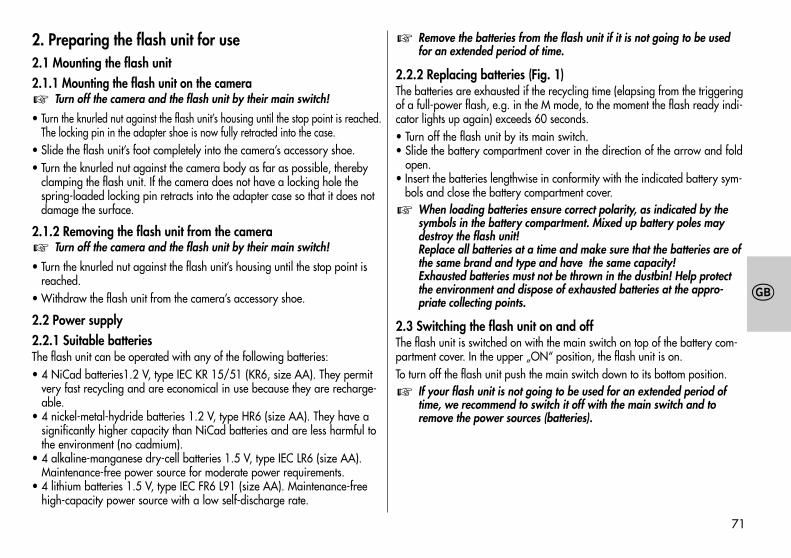
71
�
2. Preparing the flash unit for use2.1 Mounting the flash unit2.1.1 Mounting the flash unit on the camera
Turn off the camera and the flash unit by their main switch!
• Turn the knurled nut against the flash unit’s housing until the stop point is reached.The locking pin in the adapter shoe is now fully retracted into the case.
• Slide the flash unit’s foot completely into the camera’s accessory shoe.• Turn the knurled nut against the camera body as far as possible, thereby
clamping the flash unit. If the camera does not have a locking hole thespring-loaded locking pin retracts into the adapter case so that it does notdamage the surface.
2.1.2 Removing the flash unit from the cameraTurn off the camera and the flash unit by their main switch!
• Turn the knurled nut against the flash unit’s housing until the stop point isreached.
• Withdraw the flash unit from the camera’s accessory shoe.
2.2 Power supply2.2.1 Suitable batteriesThe flash unit can be operated with any of the following batteries:• 4 NiCad batteries1.2 V, type IEC KR 15/51 (KR6, size AA). They permit
very fast recycling and are economical in use because they are recharge-able.
• 4 nickel-metal-hydride batteries 1.2 V, type HR6 (size AA). They have asignificantly higher capacity than NiCad batteries and are less harmful tothe environment (no cadmium).
• 4 alkaline-manganese dry-cell batteries 1.5 V, type IEC LR6 (size AA).Maintenance-free power source for moderate power requirements.
• 4 lithium batteries 1.5 V, type IEC FR6 L91 (size AA). Maintenance-freehigh-capacity power source with a low self-discharge rate.
�
�
Remove the batteries from the flash unit if it is not going to be usedfor an extended period of time.
2.2.2 Replacing batteries (Fig. 1)The batteries are exhausted if the recycling time (elapsing from the triggeringof a full-power flash, e.g. in the M mode, to the moment the flash ready indi-cator lights up again) exceeds 60 seconds.• Turn off the flash unit by its main switch.• Slide the battery compartment cover in the direction of the arrow and fold
open.• Insert the batteries lengthwise in conformity with the indicated battery sym-
bols and close the battery compartment cover.When loading batteries ensure correct polarity, as indicated by thesymbols in the battery compartment. Mixed up battery poles maydestroy the flash unit!Replace all batteries at a time and make sure that the batteries are ofthe same brand and type and have the same capacity!Exhausted batteries must not be thrown in the dustbin! Help protectthe environment and dispose of exhausted batteries at the appro-priate collecting points.
2.3 Switching the flash unit on and offThe flash unit is switched on with the main switch on top of the battery com-partment cover. In the upper „ON“ position, the flash unit is on.To turn off the flash unit push the main switch down to its bottom position.
If your flash unit is not going to be used for an extended period oftime, we recommend to switch it off with the main switch and toremove the power sources (batteries).
�
�
�
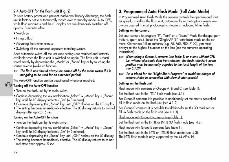
72
�
2.4 Auto-OFF for the flash unit (Fig. 2)To save battery power and prevent inadvertent battery discharge, the flashunit is factory-set to automatically switch-over to standby mode (Auto-OFF),while flash readiness and the LC display are simultaneously switched off,approx. 3 minutes after:• Switch-on• Firing a flash• Actuating the shutter release• Switching off the camera’s exposure metering system.After automatic switch-off the last-used settings are retained and instantlyavailable when the flash unit is switched on again. The flash unit is reacti-vated merely by depressing the „Mode“ or „Zoom“ key or by touching theshutter release (wake-up function).
The flash unit should always be turned off by the main switch if it isnot going to be used for an extended period!
The Auto-OFF function can be deactivated whenever required:Turning off the Auto-OFF function• Turn on the flash unit by its main switch.• Continue depressing the key combination „Select“ (= „Mode“ key + „Zoom“
key) until the LC display indicates „3m“ (= 3 minutes).• Continue depressing the „Zoom“ key until „OFF“ flashes on the LC display.• The setting becomes immediately effective. The LC display returns to normal
display after approx. 5 sec.Turning on the Auto-OFF function• Turn on the flash unit by its main switch.• Continue depressing the key combination „Select“ (= „Mode“ key + „Zoom“
key) until the LC display indicates „3m“ (= 3 minutes).• Continue depressing the „Zoom“ key until „ON“ flashes on the LC display.• The setting becomes immediately effective. The LC display returns to its nor-
mal state after approx. 5 sec.
�
3. Programmed Auto Flash Mode (Full Auto Mode)In Programmed Auto Flash Mode the camera controls the aperture and shut-ter speed, as well as the flash unit, automatically so that optimal results arealways assured in most photographic situations, including fill-in flash.Settings on the cameraSet your camera to program “P”, “Vari” or a “Scene” Mode (landscape, por-traiture, sport, etc.). Select the “Single-AF (S)” auto-focus mode on the ca-mera. On various Nikon cameras (e.g. F5, F65, F80, F100), you mustalways set the highest f-number on the lens (see the camera’s operatinginstructions).
When using a Group A camera (see Table 1) or a lens without CPU(i.e. without electronic data transmission), the flash reflector’s zoomposition must be manually adjusted to the focal length of the lens(see 5.7.2)!
Use a tripod for the “Night Shots Program” to avoid the danger ofcamera shake in connection with slow shutter speeds!
Settings on the flash unitFlash mode with cameras of Groups A, B and C (see Table 1):Set the flash unit in the “TTL” flash mode (see 4.1).For Group B cameras it is possible to additionally set the matrix-controlledfill-in flash mode on the flash unit (see 4.1.2).For Group C cameras it is possible to additionally set the 3D multi-sensorfill–in flash mode on the flash unit (see 4.1.3).Flash mode with Group D cameras (see Table 1):Set the flash unit in the D-TTL or D-TTL 3D flash mode (see 4.2).Flash mode with Group E cameras (see Table 1):Set the flash unit in the i-TTL or i-TTL BL flash mode (see 4.3).The i-TTL flash mode is only supported by the 44 AF-4i N.
�
�
73
�
As soon as the above settings have been made you can start shooting flashpictures when flash readiness is indicated (see 5.1).
4. Operating modes of the flash unit4.1 TTL flash mode (Fig. 3)The TTL flash mode is a very simple way to achieve excellent flash shots. Inthis mode exposure readings are taken by a sensor built into the camerawhich measures the light through the camera lens (TTL). The electronic controlcircuit within the camera transmits a stop signal to the flash unit after expo-sure by the correct amount of light, thereby instantly interrupting the flash.The advantage of this flash mode is that all factors influencing correct ex-posure (filters, change of aperture and focal length with zoom lenses, exten-sions for close-ups, etc.) are automatically taken into account. You need notworry about setting the flash, the camera’s electronic system automaticallydetermines the correct amount of flash light required. For the maximum flashrange please observe the distances given in the flash unit’s LC display(see 5.4) and the information in section 5.5. If flash exposure was correct,the flash unit’s LC display indicates “o.k.” for about 3 sec. (see 4.5).The TTL flash mode is supported by all camera modes (e.g. Program “P”,Aperture Priority Mode “A”, Shutter Priority Mode “S”, Vari or Scene Modes,Manual Mode “M”, etc.).
For analog cameras, a film must be loaded in the camera to test the TTLfunction. Please check whether limits regarding maximum film speed orISO value (e.g. maximum ISO 1000) are applicable to the given camerawhen in TTL mode (refer to the camera’s operating instructions)!
Various digital SLR cameras do not support the normal TTL flash modeof analog cameras. If the flash unit is used in conjunction with Group Dcameras (see Table 1), the D-TTL or D-TTL 3D flash mode must be select-ed on the flash unit (see 4.2). When using the flash unit with Group Ecameras (see Table 1) you must set the i-TTL or i-TTL BL flash mode (i-TTL only in conjunction with 44 AF-4i N) on the flash unit (see 4.3).
�
�
Setting procedure for TTL flash mode• Mount the flash unit on the camera.• Switch on the flash unit and the camera.• Continue depressing the “Mode” key until “TTL” flashes on the LC display.• The setting becomes immediately effective. The LC display returns to its nor-
mal state after approx. 5 sec.Pronounced differences in contrast, e.g. a dark subject in snow, maymake it necessary to correct the exposure settings (see 4.4).
4.1.1 Automatic TTL fill-in flash in daylight (Fig. 5 and 6)Most camera models automatically activate the fill-in flash mode when inauto program mode “P”, Vari or a Scene mode in daylight (see the camera’soperating instructions).Fill-in flash overcomes troublesome dense shadows and produces a morebalanced exposure between subject and background with contre-jour shots.The camera’s computer-controlled metering system sets the most suitablecombination of shutter speed, working aperture and flash output.
Ensure that the contre-jour light source does not shine directly into thelens as this will mislead the camera’s TTL metering system!
In this instance there is no setting or display on the flash unit for automaticTTL fill-in flash.
4.1.2 Matrix-controlled TTL fill-in flashIn this flash mode the subject and the background lighting are automaticallybalanced without overexposing the subject. The camera establishes the ex-posure setting for the ambient light by matrix metering.Various Nikon cameras support the matrix-controlled TTL fill-in flash mode(see operating instructions of the camera and Table 1).
Some cameras (F4 or F4s for example) do not support the matrix-con-trolled TTL fill-in flash mode for SPOT exposure metering. This flashmode will then either be automatically cancelled or cannot be acti-vated, so that the normal TTL flash mode will be performed.
�
�
�
74
�
When using Group A cameras (see Table 1), the matrix-controlled TTL fill-inflash mode is set on the camera or is automatically activated (see operatinginstructions of the camera). In this instance there is no setting or display onthe flash unit.When using Group B cameras (see Table 1), the matrix-controlled TTL fill-inflash mode is set and indicated on the flash unit.• Mount the flash unit on the camera.• Switch on both the flash unit and the camera.• Lightly touch the camera’s shutter release to induce a data exchange be-
tween flash unit and camera.• Continue depressing the “Mode” key until “TTL ” flashes on the LC dis-
play.• The setting becomes immediately effective. The LC display returns to its nor-
mal state after approx. 5 sec.Deactivating the matrix-controlled TTL fill-in flash mode• Continue depressing the “Mode” key on the flash unit until “TTL” (without
the symbol) flashes on the LC display.• The setting becomes immediately effective. The LC display returns to its nor-
mal state after approx. 5 sec.
4.1.3 3D multi-sensor fill-in flashThis flash mode optimizes a balanced exposure between subject and back-ground. Prior to exposure a series of almost invisible measuring preflashesare fired by the flash unit. These are evaluated by the TTL multi-sensor and thecamera’s micro-controller. The camera then adapts TTL flash exposure opti-mally to the given photographic situation (“multi-sensor fill-in flash”). When“D-AF-Nikkor” lenses are used, the camera-to-subject distance will be addi-tionally taken into account when determining the optimal flash output(“3D multi-sensor fill-in flash mode”).
Different cameras from Group C in Table 1 support the “3D multi-sensor fill-inflash”.
Some cameras (e.g. F5, F80 and F100) do not support the 3D multi-sensor fill-in flash mode for SPOT exposure metering. This flash modewill then either be automatically cancelled or it cannot be activated sothat the normal TTL flash mode will be performed.
Setting the “3D multi-sensor fill-in flash mode” on the flash unit• Mount the flash unit on the camera.• Switch on the flash unit and the camera.• Lightly touch the camera’s shutter release to induce a data exchange be-
tween the flash unit and the camera.• Continue depressing the “Mode” key until “TTL ” flashes on the LC dis-
play.• The setting becomes immediately effective. The LC display returns to its nor-
mal state after approx. 5 sec.When a lens without CPU is used, some cameras will only support thematrix-controlled fill-in flash mode or the standard TTL flash mode. Insuch cases the 3D multi-sensor fill-in flash cannot be activated. Theflash unit’s LC display will then indicate the corresponding display forthe current flash mode.
Deactivating the “3D multi-sensor fill-in flash”• Continue depressing the “Mode” key on the flash unit until “TTL” without
symbol “ “ flashes on the LC display.• The setting becomes immediately effective. The LC display returns to its nor-
mal state after approx. 5 sec.
�
�
75
�
4.2 D-TTL flash modeThis flash mode is only possible in conjunction with digital Nikon SLRcameras of Group D (see Table 1). Digital SLR cameras do not supportthe normal TTL flash mode of analog cameras.
The D-TTL flash mode is an advanced variant of the normal TTL flash mode ofanalog cameras. Prior to shooting a series of weakly visible measuring pre-flashes are fired by the flash unit. The camera evaluates the reflected pre-flash light so that the subsequent flash exposure is optimally adapted to theprevailing photographic situation (see operating instructions of your camera). Setting procedure• Mount the flash unit on the camera.• Switch on the flash unit and the camera.• Lightly touch the camera’s shutter release for data exchange between flash
unit and camera.• Continue to depress the “Mode” button until “D-TTL” flashes on the LC dis-
play.• The setting becomes instantly effective. The LC display returns to its normal
state after approx. 5 sec.
4.2.1 D-TTL 3D flash modeIn this mode with D-TTL flash control (see above) the camera additionallytakes into account the flash-to-subject distance.
This flash mode is only available with “D-AF Nikkor lenses”. Some came-ras do not support the D-TTL 3D flash mode for SPOT exposure metering.This flash mode will then either be automatically cancellled or it cannot beactivated so that the normal D-TTL flash mode will be performed.
To set the D-TTL 3D flash mode the flash head must be in the normal position,i.e. it must not be swivelled down.For D-TTL 3D flash mode, both the camera and the lens must support the eva-luation of distance data (see operating instructions for the camera and speci-fications of the lens).
�
�Setting procedure• Mount the flash unit on the camera.• Switch on the flash unit and the camera.• Lightly touch the camera’s shutter release to induce a data exchange be-
tween the flash unit and the camera.• Continue depressing the “ MODE “ key on the flash unit until “D TTL“ and
the “ “symbol flash in the LC display.• The setting becomes immediately effective and is automatically saved after
5 seconds.
4.3 i-TTL flash modeThis flash mode is only available for Nikon digital SLR cameras ofGroup E (see Table 1) in conjunction with the 44 AF-4i N flash unit.The standard TTL flash mode of analog cameras is not supported bythe digital SLR cameras.
i-TTL flash mode is an advanced variant of the standard TTL flash control ofanalog cameras. When shooting a picture, several weakly visible preflashesare fired by the flash unit prior to exposure. The camera then evaluates thereflected preflash light so that the subsequent flash exposure is optimallyadapted to the prevailing photographic situation (see operating instructionsof the camera).Setting procedure• Mount the flash unit on the camera.• Switch on the flash unit and the camera.• Lightly touch the camera’s shutter release to induce a data exchange be-
tween the flash unit and the camera.• Continue depressing the “ MODE “ key on the flash unit until “ TTL “ flashes
in the LC display. When using Group E cameras, the i-TTL flash mode isautomatically activated on the flash unit. The “ i “ symbol is not indicated.
• The setting becomes instantly effective and is automatically saved after5 sec.
�
76
�
4.3.1 i-TTL BL flash modeIn this mode with i-TTL flash control (see above) the camera additionally takesinto account data relating to the flash-to-subject distance.
This flash mode is only possible in conjunction with “ D-AF Nikkorlenses “. Some cameras do not support the i-TTL BL flash mode forSPOT exposure metering. This flash mode will then either be automa-tically cancelled or it cannot be activated so that the normal i-TTL flashmode will be performed.
For the i-TTL BL flash mode, both the camera and the lens must support theevaluation of distances (see operating instructions for the camera and specifi-cations for the given lens). Some cameras only support the i-TTL flash modefor SPOT exposure metering. The i-TTL BL flash mode can then not be acti-vated.Setting procedure• Mount the flash unit on the camera.• Switch on the flash unit and the camera.• Lightly touch the camera’s shutter release to induce a data exchange be-
tween the flash unit and the camera.• Continue to depress the “ MODE “ button on the flash unit until “TTL“ and
the symbol flash on the LC display. The “i“ symbol is not indicated.• The setting becomes instantly effective and is automatically saved after
5 sec.
4.4 Manual TTL flash exposure correctionThe TTL auto flash mode of most cameras is matched to a 25 % degree oflight reflection by the subject (average amount of light reflected by subjectsshot with flash). Consequently, a dark background that absorbs a great dealof light, or a bright background that reflects a great deal of light, can resultin under- or overexposure, respectively.To offset this effect a correction value can be set on some cameras to manual-ly match the TTL flash exposure (or D-TTL flash exposure / i-TTL flash expo-sure on digital SLR cameras) to the photographic situation. The actual extent
�
of correction depends on the contrast prevailing between subject and back-ground!
A dark subject in front of a bright background: Positive correctionvalue. Light subject in front of a dark background: Negative correc-tion value. Correction value settings can change the maximum flashrange indicated on the flash unit’s LC display and match it to the givencorrection value (depends upon the camera model)!
Exposure correction by changing the lens diaphragm is not possible becausethe camera’s automatic exposure system will automatically regard the changeddiaphragm as the normal working aperture.
After the exposure do not forget to reset the TTL flash exposure cor-rection back to the normal value on the camera!
Depending on the given type of camera, the manual TTL flash expo-sure correction must be set either on the camera or on the flash unit.Please refer to the indications given in the corresponding cameramanual.When using a Group A camera (see Table 1) this setting must alwaysbe made on the camera. It cannot be made on the flash unit.
Setting on the flash unit• Mount the flash unit on the camera.• Switch on the flash unit and the camera.• Lightly touch the camera’s shutter release to induce a data exchange be-
tween the flash unit and the camera.• Continue depressing the “Select” key combination (= “Mode” key +
“Zoom” key) until EV (Exposure Value) is indicated on the LC display.Alongside EV, the set correction value is flashing on the display.
• While the correction value is flashing, a positive value can be adjustedwith the “Zoom” key, and a negative value with the “Mode” key.
The setting range for the correction value extends from -3EV to +1EV in 1/3stop increments.
�
�
�
77
�
The setting becomes immediately effective. After approx. 5 sec. the LC dis-play returns to its normal state.If the camera is used with a CPU lens, then EV will flash alongside the aper-ture symbol on the flash unit’s LC display to indicate that a manual correctionvalue has been set for flash exposure.If the camera is used with a lens without CPU, then the adjusted manual cor-rection value for flash exposure will be displayed on the flash unit in place ofthe aperture symbol and the EV exposure value. Instead of the maximum flashrange, the flash unit indicates its guide number. To determine the maximumflash range of the flash unit please refer to the formula given in section 5.4.6.
Many cameras offer the facility to set a manual correction value di-rectly on the camera. In such an instance we advise setting the cor-rection value either on the camera or on the flash unit.
Cancelling manual TTL flash exposure correction on the flash unit• Continue depressing the “Select” key combination (= “Mode” key +
“Zoom” key) until EV is indicated on the LC display.• The set correction value flashes alongside EV on the display.• While the correction value is flashing, set the correction value at 0.0 with
the “Zoom” key or the “Mode” key, thereby cancelling manual TTL flashexposure correction.
The setting becomes immediately effective. After approx. 5 sec. the LC dis-play returns to its normal state.
4.5 Correct exposure indication in TTL flash mode (Fig. 4)The “o.k.” correct exposure confirmation only appears in the flash unit’s LCdisplay if the shot was correctly exposed in TTL flash mode or its correspond-ing advanced variants (e.g. 3D-TTL, D-TTL, D-TTL 3D, i-TTL, i-TTL BL, etc.).If “o.k.” is not displayed after the exposure, then this means that the shotwas underexposed. The shot will then have to be repeated with the nextsmaller f-number (e.g. f/8 instead of f/11) or the distance to the subject orthe reflecting surface (e.g. when bouncing the flash) must be reduced.Please observe the maximum flash range indicated on the flash unit’s LC dis-play (see 5.4.1) and the information given in section 5.5.
�
Also refer to section 5.3 regarding correct exposure indication in thecamera’s viewfinder!
4.6 Underexposure warning in TTL flash modeIn certain modes (for example “P” and “A”), some Group C, D and E Nikoncameras listed in Table 1 will give underexposure warning for flash shots byway of aperture increments (EV) on the flash unit’s LC display (see operatinginstructions of the camera).If the “OK” correct exposure confirmation does not light up on the flash unitafter a flash shot was taken, or if the flash symbol in the camera viewfinderflashes, then the flash unit’s LC display briefly indicates the underexposurevalue between -0.3 EV and -3.0 EV in one-third increments.In borderline instances it may occur that “o.k.” is not displayed on the flashunit but the flash symbol in the camera viewfinder flashes. In such an eventthe exposure will nevertheless be correct.
To enable underexposure indication, the TTL mode or an advancedvariant of TTL flash mode (e.g. 3D-TTL, D-TTL 3D, i-TTL, i-TTL BL, etc.)must be set on the flash unit.
4.7 Manual flash modeSet “A” aperture priority or the manual mode “M” or “X” on the camera.Select the aperture and shutter speed (with “M”) on the camera according tothe given photographic situation (see the camera’s operating instructions).
4.7.1 Manual flash mode M with full light outputIn this mode the flash unit always fires uncontrolled flashes at full light output.Adaptation to the given photographic situation is by selecting a corres-ponding aperture setting on the camera. When using Group C, D and Ecameras, the flash unit’s LC display will indicate the flash-to-subject distancerequired for a correct exposure (see also 5.4.2).
�
�
78
�
Setting procedure for the manual flash mode M• Turn on the flash unit by its main switch.• Continue depressing the “Mode” key until “M” flashes on the LC display.• The setting becomes immediately effective. The LC display returns to its nor-
mal state after approx. 5 sec.
4.7.2 MLo manual flash mode with partial light output levelsIn this mode the flash unit always fires an uncontrolled flash at a manually setpartial light output level (Low). Adaptation to the prevailing photographic s-ituation is by selecting an appropriate partial output level or by setting a cor-responding aperture on the camera. The flash unit’s LC display panel willindicate the distance required for correct flash exposure (also see 5.4.2).Setting procedure for the manual flash mode MLo• Turn on the flash unit with the main switch.• Continue depressing the “Mode” key until “MLo” flashes on the LC display.• The setting becomes instantly effective. After about 5 sec. the LC display returns
to its normal state.
4.8 Flash techniques4.8.1 Bounce flashPhotos shot with full frontal flash are easily recognized by their harsh, denseshadows. This is often associated with a sharp drop in light from the fore-ground to the background. This phenomenon can be avoided with bounceflash because the diffused light will produce a soft and uniform rendition ofboth the subject and the background. For this situation the reflector is turnedin such a manner that the flash is bounced off a suitable reflective surface(e.g. ceiling or wall of the room).The reflector can be turned vertically up to 90°. The reflector head is mecha-nically interlocked in its basic position. Press the pushbutton to unlock andturn the reflector head.
When turning the reflector vertically, it is essential to ensure that it is movedby a sufficiently wide angle so that direct light can no longer fall on the sub-ject. Consequently, always turn the reflector at least to the 60° lock-in posi-tion. The distance readings on the LC display will disappear. The flash-to-subject distance via the ceiling or wall is an unknown magnitude.The light bounced off the reflecting surfaces produces a soft and uniform illu-mination of the subject. The reflecting surface must be white or have a neu-tral colour, and it must not be structured (e.g. wooden beams in a ceiling) asthese might cause shadows. For colour effects just select the reflective surfacein the desired colour.
Take into account that the maximum flash range is considerably dimi-nished when bouncing the flash. The following rule of thumb will helpyou determine the maximum flash range for a room of normal height:
guide numberMaximum flash range = —————————————
lighting distance x 2
4.8.2 Close-ups / MacrophotographyThe flash reflector can be swivelled down by an angle of -7° to compensatefor parallax error. For this purpose depress the unlocking button of the re-flector and fold down the reflector.For close-ups it is necessary to ensure that certain minimum lighting distancesare maintained to avoid overexposure.
The minimum lighting distance is approx. 10 per cent of the maximumflash range indicated on the LC display. Since the maximum flashrange is not indicated on the LC display when the reflector is swivelleddown, then be guided by the maximum flash range indicated by theflash unit when the reflector is in its normal position!
�
�
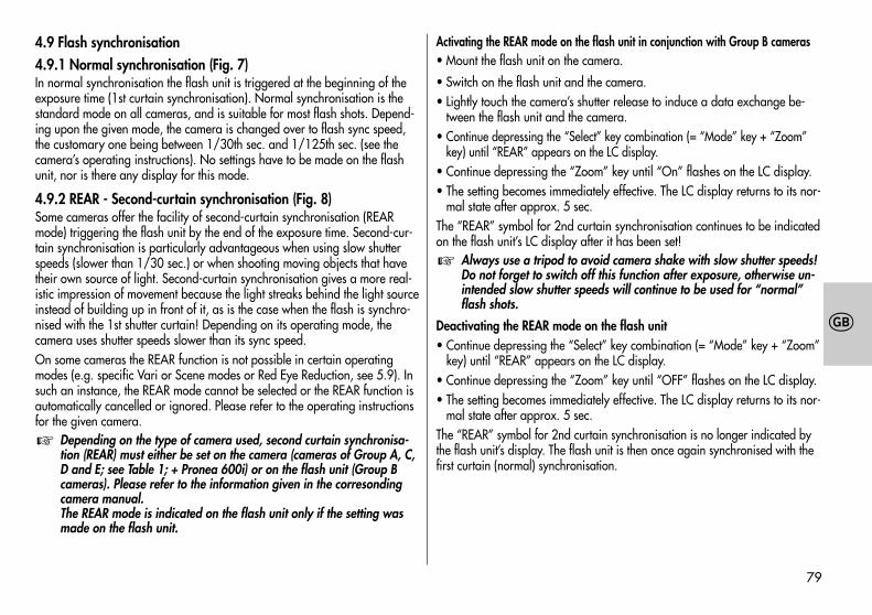
79
�
4.9 Flash synchronisation4.9.1 Normal synchronisation (Fig. 7)In normal synchronisation the flash unit is triggered at the beginning of theexposure time (1st curtain synchronisation). Normal synchronisation is thestandard mode on all cameras, and is suitable for most flash shots. Depend-ing upon the given mode, the camera is changed over to flash sync speed,the customary one being between 1/30th sec. and 1/125th sec. (see thecamera’s operating instructions). No settings have to be made on the flashunit, nor is there any display for this mode.
4.9.2 REAR - Second-curtain synchronisation (Fig. 8)Some cameras offer the facility of second-curtain synchronisation (REARmode) triggering the flash unit by the end of the exposure time. Second-cur-tain synchronisation is particularly advantageous when using slow shutterspeeds (slower than 1/30 sec.) or when shooting moving objects that havetheir own source of light. Second-curtain synchronisation gives a more real-istic impression of movement because the light streaks behind the light sourceinstead of building up in front of it, as is the case when the flash is synchro-nised with the 1st shutter curtain! Depending on its operating mode, thecamera uses shutter speeds slower than its sync speed.On some cameras the REAR function is not possible in certain operatingmodes (e.g. specific Vari or Scene modes or Red Eye Reduction, see 5.9). Insuch an instance, the REAR mode cannot be selected or the REAR function isautomatically cancelled or ignored. Please refer to the operating instructionsfor the given camera.
Depending on the type of camera used, second curtain synchronisa-tion (REAR) must either be set on the camera (cameras of Group A, C,D and E; see Table 1; + Pronea 600i) or on the flash unit (Group Bcameras). Please refer to the information given in the corresondingcamera manual.The REAR mode is indicated on the flash unit only if the setting wasmade on the flash unit.
�
Activating the REAR mode on the flash unit in conjunction with Group B cameras• Mount the flash unit on the camera.
• Switch on the flash unit and the camera.• Lightly touch the camera’s shutter release to induce a data exchange be-
tween the flash unit and the camera.• Continue depressing the “Select” key combination (= “Mode” key + “Zoom”
key) until “REAR” appears on the LC display.• Continue depressing the “Zoom” key until “On” flashes on the LC display.• The setting becomes immediately effective. The LC display returns to its nor-
mal state after approx. 5 sec.The “REAR” symbol for 2nd curtain synchronisation continues to be indicatedon the flash unit’s LC display after it has been set!
Always use a tripod to avoid camera shake with slow shutter speeds!Do not forget to switch off this function after exposure, otherwise un-intended slow shutter speeds will continue to be used for “normal”flash shots.
Deactivating the REAR mode on the flash unit• Continue depressing the “Select” key combination (= “Mode” key + “Zoom”
key) until “REAR” appears on the LC display.• Continue depressing the “Zoom” key until “OFF” flashes on the LC display.• The setting becomes immediately effective. The LC display returns to its nor-
mal state after approx. 5 sec.The “REAR” symbol for 2nd curtain synchronisation is no longer indicated bythe flash unit’s display. The flash unit is then once again synchronised with thefirst curtain (normal) synchronisation.
�
80
�
4.9.3 Slow synchronisation / SLOWIn certain operating modes, some cameras permit slow flash synchronisation(“SLOW”) which will provide added prominence to the background at lowerambient light levels. This is achieved by matching the shutter speed to theambient light. Accordingly, shutter speeds slower than the flash sync speed(e.g. shutter speeds up to 30 s) are automatically adjusted by the camera.Some cameras automatically activate SLOW synchronisation in connectionwith certain programs (e.g. night shots program, etc.) or permit slow syn-chronisation to be set (see camera’s instruction manual). No settings aremade on the flash unit nor is there any display for this mode.
Use a tripod to avoid camera shake with slow shutter speeds!
5. Flash unit and camera functions5.1 Flash readiness indicationThe flash readiness symbol lights up on the flash unit when the flash capa-citor is charged, thereby indicating that flashes can be fired for the next shot.Flash readiness is also transmitted to the camera for corresponding display inthe viewfinder (see 5.3).If a picture is shot before flash readiness is signalled in the camera’s view-finder, then the flash unit will not be triggered so that the exposure may beincorrect if the camera has changed over to flash sync speed in the meantime(see 5.2).
5.2 Automatic flash sync speed controlDepending upon the camera model and camera mode, the shutter speed ischanged to flash sync speed when flash readiness is reached (see the came-ra’s operating instructions).Shutter speeds faster than the flash sync speed cannot be set or will automati-cally be converted to flash sync speed. Various cameras have a sync speedrange, e.g. 1/30th sec. to 1/125th sec. (see the camera’s operating instruc-tions). The actual sync speed set by the camera depends upon the cameramode, the ambient light and the focal length of the lens used.
�
Shutter speeds slower than the flash sync speed can be set, depending uponthe given camera model and the selected flash synchronisation (see also4.9.2 and 4.9.3).
Various digital cameras do not provide automatic flash sync speedcontrol. They are equipped with a diaphragm shutter and permit theuse of flash at all shutter speeds. Should you require the full light out-put of the flash unit we recommend not to use shutter speeds fasterthan 1/125 sec.
5.3 Displays in the camera viewfinderGreen flash symbol illuminatedCommand to switch on or use the flash unit.Red flash symbol illuminatedThe flash unit is ready for firing.Red flash symbol remains illuminated after shooting or goes out momentarilyThe exposure was correct.Red arrow symbol flashes after shootingThe shot was underexposed.
Refer to the operating instructions to establish whatever is applicableto the displays in the viewfinder for the given camera model.
5.4 Information in the LC displayNikon cameras of Group B, C, D and E (see Table 1) transmit the ISO, focallength of the lens (mm) and f-stop to the flash unit and the flash unit thenautomatically adapts its settings accordingly. The flash unit calculates themaximum flash range from these values and its own guide number. Flashmode, maximum flash range, aperture and zoom reflector position are allindicated on the flash unit’s LC display.If the flash unit is operated without having received any data from the ca-mera (e.g. when the camera is switched off or if a camera from Group A isbeing used), then only the selected flash mode, the reflector position and“M.Zoom” will be displayed. The aperture and the maximum flash range will
�
�
81
�
only be displayed after the flash unit has received the corresponding datafrom the camera.
Auto Zoom, aperture and maximum flash range are only displayed inconjunction with Group B, C, D and E cameras (see Table 1) if these arefitted with an AF lens or a lens with CPU.
5.4.1 Maximum flash range indication in TTL flash modeThe flash unit’s LC display indicates the maximum flash range. The indicatedvalue relates to a factor of 25 % of light reflection by the subject, whichapplies to most photographic situations. Pronounced deviations from this re-flection factor, e.g. highly reflective or poorly reflecting objects, can influencethe maximum flash range of the flash unit.Always observe the maximum flash range indicated by the flash unit’s LCdisplay. The subject should be within approx. 40 % to 70 % of the indicatedvalue. This gives the electronic circuit sufficient scope for compensation. Toavoid overexposure, the minimum flash-to-subject distance should not be lessthan 10 % of the indicated value. Adaptation to the given photographic si-tuation is possible by changing the aperture setting on the lens.
5.4.2 Maximum flash range indication in manual flash modes Mand MLo
The flash unit’s LC display indicates the distance to be maintained for correctexposure of the subject. Adaptation to the given photographic situation isachieved by changing the aperture setting on the lens and selecting either“M” for full light output or “MLo” for partial light output (see 4.7).
5.4.3 Exceeding the display rangeThe flash unit can indicate a maximum range of 199 m or 199 ft. Thisdisplay range can be exceeded in the event of high ISO values (e.g. ISO6400) and large aperture openings. An arrow or triangle after the distancevalue indicates that the display range has been exceeded.
�
5.4.4 Blanking out the maximum flash range displayThe flash unit’s LC display does not indicate any distances when the reflectorhead is swivelled up or down out of its normal position!
5.4.5 “FEE” error indication on the flash unit’s LC-displayOn some cameras and in some camera modes (e.g. program “P”, Vari-pro-grams, “S” shutter priority mode) it is necessary to set the aperture ring ofthe lens to the maximum f-number. Otherwise the message “FEE” (= error)will be indicated on the flash unit’s LC-display or the camera. In such aninstance please check the settings on the camera or lens (see operatinginstructions of the camera).
5.4.6 Guide number indication when using lenses without CPULenses without CPU (i.e. without electronic data transmission) do not transmitto the camera any electric information about focal length and aperture set-ting. If such a lens is used on a Group B, C, D and E camera, then the flashunit will only receive from the camera the data relating to ISO. The positionof the zoom reflector must be set manually (see 5.7.2).In conjunction with certain cameras, the flash unit’s LC display indicates, inthis instance, the guide number for the current setting instead of the distance.The maximum flash range is the result of the following formula:
guide numberMaximum flash range = ——————————
aperture
Refer to the instructions regarding the flash-to-subject distance insection 5.5. The guide number is not indicated when the reflector isfolded down.
�
82
�
5.4.7 Meter-Feet changeover (m - ft)The maximum flash range indicated by the flash unit’s LC display can beeither in meter (m) or feet (ft). To change between the two, proceed in the fol-lowing manner:• Turn off the flash unit by its main switch.• Keep the “Select” key combination depressed (= “Mode” key + “Zoom” key).• Turn on the flash unit by its main switch.• Release the “Select” key combination (= “Mode” key + “Zoom” key).• The flash range indication changes from m to ft or from ft to m.
5.5 Determining the maximum flash range with the guide number tableGroup A cameras do not transmit to the flash unit the ISO, aperture andfocal length data. Consequently, the flash unit’s LC display will not indicatethe camera’s aperture and the maximum flash range. In such an event youcan determine the maximum flash range with the help of Table 2 listed in theAddendum (see section 10).Use the following formula:
guide numberMaximum flash range = ——————————
aperture
This formula does not apply to bounce flashes, e.g. when the reflectoris folded down!
Example:The lens has a focal length of 50 mm and ISO is 100. The guide number givenfor this combination in Table 2 in the Addendum is 34. Set on the camera or lensthe aperture f/4, for example. The above formula can now be used to calculatethe maximum flash range:
guide number 34Maximum flash range = ———————————— = 8,5 m
aperture 4
For the manual flash mode “M” at full light output this means that the dis-tance to the subject should be 8,5 m to obtain correct exposure results.
�
For TTL flash mode this means that 8,5 m should be the maximum distance tothe subject. However, to give the camera’s electronic system sufficient scopefor light output control the subject should be positioned somewhere between40 % and 60 % of the calculated range. For the above example this means adistance of between 3,4 m and 5,1 m. For close-ups it is necessary to ensurethat a minimum distance of 10 % of the calculated value is observed in orderto avoid overexposure. For the above example the minimum distance is 10 %of 8,5 m = 0,85 m.
Please note that the maximum flash range is related to subjects with a25 % reflectivity which applies to most shooting situations. Pronounceddeviations from this reflectivity, e.g. highly or poorly reflective subjects,can influence the maximum flash range of the flash unit.
5.6 LC display illuminationKeep the “Mode” or “Zoom” key depressed for approx. 10 sec. to activatethe flash unit’s LC display illumination. The LC display illumination is switchedoff when a flash is triggered.
The settings on the flash unit are not changed when the above keysare pressed for the first time!
If the shot was correctly exposed in TTL flash mode, then the LC display illu-mination will be activated during “o.k.” display (see 4.5).
5.7 Motor zoom reflectorThe reflector’s illumination angle equals the coverage of a lens of 24 mm fo-cal length.
�
�
83
�
5.7.1 “Auto Zoom”If the flash unit is operated with a Group B, C, D or E camera with CPU lens,its zoom reflector position will be automatically adapted to the focal length ofthe lens. When the flash unit is turned on, the LC display will indicate “AutoZoom” and the current reflector position.Automatic reflector adaptation commences with focal lengths as of 24 mm. Ifa lens with a focal length of less than 24 mm is used, the value “24” mm orwill start to flash on the LC display to warn you of vignetting because theflash unit will not fully illuminate the picture right out to the image corners.
For lenses with focal lengths as of 20 mm a wide-angle diffuser canbe used (optional extra, see section 7). The flash head must then beset to the 24 mm position.
5.7.2 Manual zoom mode “M. Zoom”With Group A cameras, or when a lens without CPU is used (e.g. manualfocus lens), it is necessary to adjust the flash reflector’s zoom position ma-nually to the focal length of the lens. In this case, auto-zooming is not pos-sible. The flash unit’s LC display indicates “M.Zoom” (for manual zoom set-ting) and the current zoom position (mm).• The following reflector positions can be selected by repeated depression of
the “Zoom” key:24 mm - 28 mm - 35 mm - 50 mm - 70 mm - 85 mm - 105 mm.No warning is given if the zoom reflector setting is incorrect!
If you do not always need the full guide number and maximum flashrange of the flash unit you can leave the zoom reflector at the positionfor the shortest focal length of the zoom lens. This will provide fulllight coverage of the image corners and eliminate the need for per-manent adaptation to the lens focal length.
Example:A zoom lens with a focal length range of 35 mm to 105 mm is being used: Inthis case set the flash unit’s zoom reflector to 35 mm.
�
�
5.7.3 Manual zoom mode instead of “Auto Zoom”When using Group B, C, D and E cameras with CPU lenses, the position ofthe zoom reflector can be manually changed, for instance to achieve specificlighting effects (e.g. hot-spot, etc.). Repeated depression of the “Zoom” keyon the flash unit will successively select the following reflector positions:24 mm - 28 mm - 35 mm - 50 mm - 70 mm - 85 mm - 105 mmThe flash unit’s LC display indicates “M.Zoom” for manual zoom setting andthe current zoom position (mm). The setting becomes instantly effective. Thedisplay is switched back to its normal state after approx. 5 sec.
If manual adjustment of the zoom reflector results in vignetting so thatthe flash will not cover the image corners, then the reflector positionindicated on the flash unit’s display will start flashing as a warning.
Example:• You are using a lens focal length of 50 mm.• A reflector position of 70 mm has been manually adjusted on the flash unit
(“M.Zoom” is displayed).• “70” mm for the zoom position starts flashing on the flash unit’s LC display
because the image corners will not be fully illuminated.Returning to “Auto Zoom”There are various ways to return to “Auto Zoom”:• Continue pressing the “Zoom” key on the flash unit until “Auto Zoom” appears
on the display. The setting becomes instantly effective. The LC display returns toits normal state after approx. 5 sec.
Or:• Briefly turn off the flash unit by its main switch. When the flash unit is
turned on again the display of the flash unit will indicate “Auto Zoom”.
�
84
�
5.7.4 Extended zoom modeThe extended zoom mode (Ex) reduces the focal length setting of the flashunit by one step as compared to the focal length of the camera lens! Theresulting wider light coverage inside rooms provides additional stray light(reflections) to achieve a softer flash illumination.Example of extended zoom mode:The focal length set on the camera lens is 35 mm. The extended zoom modesets a 28 mm reflector position on the flash unit but 35 mm continues to beindicated on the LC display!The extended zoom mode is only possible in the “Auto Zoom” mode with GroupB, C, D and E cameras as listed in Table 1 and CPU lenses with focal lengths asof 28 mm.Since the initital position of the zoom reflector is 24 mm, a focal length of less than28 mm will cause “24” mm to flash on the LC display thereby warning the userthat the required reflector position for the extended zoom mode cannot be set.
Shots taken with a 24 mm focal length setting will be correctly illumi-nated right out to the image corners by the flash unit also in extendedzoom mode!
Turning on the extended zoom mode• Continue depressing the “Select” key combination (= “Mode” key + “Zoom”
key) until “Ex” appears on the LC display.• Continue depressing the “Zoom” key until “On” flashes on the LC display.• The setting becomes instantly effective. The LC display returns to its normal
state after approx. 5 sec.After the setting procedure, the “Ex” symbol for the extended zoom mode willcontinue to be indicated on the flash unit’s LC display!
Please note that the wider illumination coverage in extended zoommode results in a diminished maximum flash range!
Turning off the extended zoom mode• Continue depressing the “Select” key combination (= “Mode” key + “Zoom”
key) until “Ex” appears on the LC display.
�
�
• Continue depressing the “Zoom” key until “OFF” flashes on the LC display.• The setting becomes instantly effective. The LC display returns to its normal
state after approx. 5 sec.The “Ex” symbol for the extended zoom mode will no longer be indicated onthe flash unit’s LC display!
5.8 AF measuring beamThe AF measuring beam is activated by the camera electronics when theambient lighting conditions are insufficient for automatic focusing. The AFbeam emitter projects a striped pattern on to the subject, and the camerauses this pattern to focus automatically. The AF beam has a range of approx.6 m to 9 m (with a 50 mm/f/1.7 standard lens). Parallax error between lensand AF red light emitter limits the close-up range of the AF measuring beamto approx. 0.7 m - 1 m.
The AF mode “Single-AF (S)” must be set on the camera so that the AFmeasuring beam can be activated by the camera (see the camera’soperating instructions). Zoom lenses with a small initial lens aperturemay significantly reduce the range of the AF measuring beam!The striped pattern of the AF measuring beam only supports the ca-mera’s central AF sensor. When using cameras with several AF sen-sors we recommend to only activate the camera’s central AF meteringarea (see the camera’s operating instructions). If a decentral AF sensoris manually selected by the photographer, or automatically by thecamera, then the emitter of the flash unit’s AF measuring beam willnot be activated.In such instances some cameras will use the AF illuminator integratedin the camera (see operating instructions of the camera).
�
85
�
5.9 Preflashes for red-eye reductionRed eyes are always the result of a physical effect. It arises whenever a per-son looks more or less straight into the camera , the ambient light is relativelydark, and the flash unit is mounted on or directly next to the camera. Theflash unit illuminates the back of the eyes, revealing the blood-filled retinathrough the pupil. This is recorded by the camera as a red spot in the eyes.The red-eye reduction facility brings about a significant improvement in thisrespect. When this function is used, the flash unit triggers three weakly visiblepreflashes prior to shutter operation, which are followed by the main flash.These preflashes induce the pupils to close down, thereby diminishing thered-eye effect.The preflash function is set on the camera. An activated preflash function isindicated on the camera’s LC display by a corresponding symbol (see opera-ting instructions of the camera). There is no setting made on the flash unit,nor an information given on the flash unit’s display.The preflash function for red-eye reduction is only possible with cameras thatsupport this mode (see operating instructions of the camera)!On some cameras, the red-eye reduction will only support the flash unit builtinto the camera or an extra illuminator incorporated in the camera body (seeoperating instructions of the camera)!Second curtain synchronisation (REAR) will not work when the preflash func-tion is used!
5.10 AUTO FLASH / Triggering controlSome cameras prevent the triggering of a flash if the existing ambient light issufficient for an exposure in normal mode. No flash will be fired when thecamera’s shutter release is pressed. On various cameras, the triggering con-trol function only works in the full auto mode or Program “P” or it must beactivated on the camera (see camera manual).
5.11 Return to basic settingThe flash unit returns to its basic setting when the “Mode” key is kept de-pressed for at least three seconds.The following settings are adjusted:• The “TTL” flash mode.• The “Auto-OFF” (3m On) function is activated.• The automatic zoom mode “Auto Zoom”.• The extended-zoom mode “Ex” is cancelled.• The flash exposure correction value on the flash unit is cancelled.• The REAR function on the flash unit is deactivated.
86
�
6. Special remarks concerning the camerasThe multitude of camera models and their features make it impossible to de-tail all camera-specific capabilities, settings, displays, etc. For more detailsconcerning the operation of a flash unit please refer to the correspondingchapters in the operating instructions for the given camera!
6.1 Special functions not supported in flash mode6.1.1 Program shiftA program shift (paired shutter/aperture setting) cannot be carried out in theprogrammed auto mode P when the flash unit is switched on (see operatinginstructions of the camera).
7. Optional extrasNo guarantee is given for malfunctions and damage to the flash unitcaused by the use of accessories from other manufacturers!
• 20 mm wide-angle diffuser(Item No. 000044217)For full illumination in conjunction with lenses of 20 mm and up. The rangeis reduced by the factor 1.4 due to the corresponding loss of light.
• Colour filter set 44-32(Item No. 00004432A))Consists of 4 colour filters to achieve special lighting effects, plus a clear fil-ter to hold colour foils in any colour.
• Mecabounce 44-90(Item No. 000044900)A diffuser to achieve soft illumination in the simplest possible manner. Theeffect is very impressive because the pictures are given a very soft atmos-phere. Facial colours are rendered more naturally. However, loss of lighthalves the maximum flash range.
• Bounce diffuser 54-23(Item No. 000054236)The soft directed light diminishes dense shadows.
�
87
�
8. Advice in the event of a faultShould the LC display indicate meaningless information or should the flashunit not work properly in the individual modes, then switch off the flash unitfor about 10 seconds by its main switch. Check the camera settings and findout if the flash unit’s foot is correctly mounted in the camera’s accessory shoe.The flash unit must operate properly when it is switched on again. Contactyour local dealer should this not be the case.
9. Maintenance and careRemove any grime and dust with a soft, dry or silicon-treated cloth. Neveruse detergents that could damage plastic parts.
Forming the flash capacitorThe flash capacitor incorporated in the flash unit undergoes a physical changewhen the flash unit is not switched on for prolonged periods of time. For thisreason it is necessary to switch on the flash unit for approx. 10 minutes every3 months (see 2.4!). The batteries must supply sufficient power for flash readi-ness to be indicated within 1 minute after the flash unit was switched on.
88
�
10. Technical dataMaximal guide number at ISO 100/21°, 105 mm zoom:In the metric system: 44; in the imperial system: 144
Flash durations:Approx. 1/200th to 1/20,000th sec. (in TTL mode)In M mode approx. 1/200th sec. at full light outputIn MLo mode approx. 1/200th sec.
Colour temperature:approx. 5600 K
Film speed:ISO 6 to ISO 6400Synchronisation:Low-voltage ignition
Number of flashes:approx. 85 with NiCad batteries (600 mAh)approx. 205 with NiMH batteries (1200 mAh)approx. 240 with high-capacity alkaline manganese batteries
(at full light output)
Recycling time:approx. 4 s with NiCad batteriesapprox. 4 s with NiMH batteriesapprox. 5 s with high-capacity alkaline manganese batteries
(at full light output)
Swivelling range and locking positions of flash head:Upwards / downwards: 60°, 75°, 90° / -7°
Dimensions approx. in mm:75 x 125 x 108 (W x H x D)
Weight:Flash unit with power sources: approx. 400 g
Included:Flash unit, Operating Instructions
Disposal of batteriesDo not dispose of spent batteries with domestic rubbish.Please return spent batteries to collecting points should they exist in yourcountry!Please return only fully discharged batteries.Normally, batteries are fully discharged if:- The device they powered switches itself off and indicates "Spent Batteries".- They no longer function properly after prolonged use.To ensure short-circuit safety please cover the battery poles with adhesivetape.
Errors excepted. Subject to changes!

89
�
✍ ✍
90
�
1. Per la vostra sicurezza . . . . . . . . . . . . . . . . . . . . . . . . . . . . . . . 91Tabella 1 . . . . . . . . . . . . . . . . . . . . . . . . . . . . . . . . . . . . . . . . . 92
2. Preparazione del flash . . . . . . . . . . . . . . . . . . . . . . . . . . . . . . . 932.1 Montaggio del flash . . . . . . . . . . . . . . . . . . . . . . . . . . . . . . . . . 932.1.1 Montaggio del flash sulla camera . . . . . . . . . . . . . . . . . . . . . . . 932.1.2 Smontaggio del flash dalla camera . . . . . . . . . . . . . . . . . . . . . . 932.2 Alimentazione . . . . . . . . . . . . . . . . . . . . . . . . . . . . . . . . . . . . . 932.2.1 Scelta delle pile o delle batterie . . . . . . . . . . . . . . . . . . . . . . . . . 932.2.2 Sostituzione delle batterie . . . . . . . . . . . . . . . . . . . . . . . . . . . . . 932.3 Accensione e spegnimento del flash . . . . . . . . . . . . . . . . . . . . . . 932.4 Spegnimento automatico dell’apparecchio / Auto - OFF . . . . . . . 943. Automatismo di programma flash (flash completamento autom.) 944. Modalità del flash . . . . . . . . . . . . . . . . . . . . . . . . . . . . . . . . . . 954.1 Modo flash TTL . . . . . . . . . . . . . . . . . . . . . . . . . . . . . . . . . . . . . 954.1.1 Lampi di schiarita automatici TTL con luce diurna . . . . . . . . . . . . 954.1.2 Modo lampo di schiarita TTL con controllo a matrice . . . . . . . . . . 964.1.3 Lampo di schiarita con multisensore 3D . . . . . . . . . . . . . . . . . . . 964.2 Modo flash D-TTL . . . . . . . . . . . . . . . . . . . . . . . . . . . . . . . . . . . 974.2.1 Modo flash D-TTL-3D . . . . . . . . . . . . . . . . . . . . . . . . . . . . . . . . 974.3 Modo flash i-TTL . . . . . . . . . . . . . . . . . . . . . . . . . . . . . . . . . . . . 974.3.1 Modo flash i-TTL-BL. . . . . . . . . . . . . . . . . . . . . . . . . . . . . . . . . . 984.4 Compensazione manuale dell’esposizione TTL . . . . . . . . . . . . . . 984.5 Indicazione di corretta esposizione nel Modo flash TTL . . . . . . . . 994.6 Indicazione di sottoesposizione nel Modo flash TTL . . . . . . . . . . . 994.7 Modo flash manuale . . . . . . . . . . . . . . . . . . . . . . . . . . . . . . . . 1004.7.1 Modo flash manuale M con potenza piena . . . . . . . . . . . . . . . . . 1004.7.2 Modo flash manuale MLo con potenza ridotta. . . . . . . . . . . . . . 1004.8 Tecniche lampo. . . . . . . . . . . . . . . . . . . . . . . . . . . . . . . . . . . . 1004.8.1 Lampo riflesso . . . . . . . . . . . . . . . . . . . . . . . . . . . . . . . . . . . . 1004.8.2 Riprese macro (primo piano) . . . . . . . . . . . . . . . . . . . . . . . . . . 1014.9 Sincronizzazione flash . . . . . . . . . . . . . . . . . . . . . . . . . . . . . . 1014.9.1 Sincronizzazione normale . . . . . . . . . . . . . . . . . . . . . . . . . . . . 1014.9.2 Sincronizzazione sulla 2a tendina (REAR). . . . . . . . . . . . . . . . . 101
4.9.3 Sincronizzazione con tempi lunghi / SLOW . . . . . . . . . . . . . . . 1025. Funzioni del flash e della camera . . . . . . . . . . . . . . . . . . . . . . 1025.1 Indicazione di stato di carica del flash . . . . . . . . . . . . . . . . . . . 1025.2 Controllo automatico del tempo di sincronizzazione . . . . . . . . . 1025.3 Indicazioni sul mirino della camera . . . . . . . . . . . . . . . . . . . . . 1035.4 Indicazioni nel display LC . . . . . . . . . . . . . . . . . . . . . . . . . . . . 1035.4.1 Indicazione campo d’utilizzo nel modo TTL . . . . . . . . . . . . . . . . 1035.4.2 Indicazione del campo d’utilizzo nel Modo manuale M o MLo . 1035.4.3 Superamento del campo indicato . . . . . . . . . . . . . . . . . . . . . . . 1035.4.4 Soppressione dell’indicazione del campo d’utilizzo . . . . . . . . . . 1035.4.5 Segnalazione di errore “FEE” sul display LC del flash . . . . . . . . 1045.4.6 Indicazione numero guida con obiettivo con messa a fuoco manuale . 1045.4.7 Commutazione metri - piedi (m - ft). . . . . . . . . . . . . . . . . . . . . 1045.5 Determinazione del campo d’utilizzo tramite la tab. dei num. guida 1045.6 Illuminazione display LC . . . . . . . . . . . . . . . . . . . . . . . . . . . . . 1055.7 Parabola zoom motorizzata . . . . . . . . . . . . . . . . . . . . . . . . . . 1055.7.1 “Auto-Zoom” . . . . . . . . . . . . . . . . . . . . . . . . . . . . . . . . . . . . . 1055.7.2 Modo zoom manuale “M. Zoom”. . . . . . . . . . . . . . . . . . . . . . . 1055.7.3 Modo zoom manuale anziché “Auto-Zoom” . . . . . . . . . . . . . . . 1055.7.4 Modo “Zoom esteso” . . . . . . . . . . . . . . . . . . . . . . . . . . . . . . . 1065.8 Illuminatore di assistenza AF . . . . . . . . . . . . . . . . . . . . . . . . . . 1075.9 Prelampi contro l’effetto “occhi rossi” (Red-Eye-Reduction) . . . . . 1075.10 Auto-flash / Soppressione del lampo (AUTO-FLASH) . . . . . . . . 1085.11 Ritorno all’impostazione inizale (reset) . . . . . . . . . . . . . . . . . . . 1086. Avvertenze speciali della camera . . . . . . . . . . . . . . . . . . . . . . 1086.1 Funzioni speciali non supportate nel Modo flash . . . . . . . . . . . . 1086.1.1 Spostamento di programma / Programm-Shift . . . . . . . . . . . . . 1087. Accessori opzionali . . . . . . . . . . . . . . . . . . . . . . . . . . . . . . . . 1098. In caso di anomalie di funzionamento. . . . . . . . . . . . . . . . . . . 1099. Cura e manutenzione . . . . . . . . . . . . . . . . . . . . . . . . . . . . . . . 10910. Dati tecnici . . . . . . . . . . . . . . . . . . . . . . . . . . . . . . . . . . . . . . . 110
Tabella 2 . . . . . . . . . . . . . . . . . . . . . . . . . . . . . . . . . . . . . . . . 134
�
91
�
PremessaVi ringraziamo vivamente per aver acquistato un prodotto Metz e siamo lietidi potervi accogliere come nostri Clienti.Comprendiamo il vostro desiderio di provare subito il nuovo lampeggiatore.Prima di utilizzarlo, Vi consigliamo tuttavia di leggere con attenzione questeistruzioni: sarà ben speso il tempo che trascorrerete ad approfondire questomanuale. Esso vi metterà infatti nelle condizioni di utilizzare il flash corretta-mente e senza problemi e di sfruttare appieno le sue enormi potenzialità.Questo flash è adatto per le camere Nikon con modo TTL, D-TTL e i-TTL (i-TTLsolo con 44 AF -4i N). Il flash non è adatto per camere di altre marche!
Aprite il risvolto de copertina con le illustrazioni.
1. Per la vostra sicurezza• L’uso del lampeggiatore è previsto ed ammesso esclusivamente nell’am-
bito fotografico!• Non scattare il flash in prossimità di gas o liquidi infiammabili (benzina,
solventi ecc.). PERICOLO DI ESPLOSIONE!• Non fotografare mai con il lampeggiatore il conducente di un’auto, di un
autobus, di una bicicletta, di un motorino o di un treno ecc. durante laguida. A causa dell’abbagliamento il guidatore potrebbe provocare unincidente!
• Non scattare flash direttamente negli occhi ad una distanza particolar-mente ridotta! Il lampo diretto negli occhi di persone o animali può pro-vocare danni alla retina e gravi danni alla vista, in alcuni casi addiritturala cecità!
• Utilizzare esclusivamente le fonti di energia descritte e ammesse nelleistruzioni d’uso.
• Utilizzare esclusivamente le fonti di energia descritte e ammesse nelleistruzioni d’uso.
�
• Non esporre le pile o le batterie a fonti di calore eccessive come il sole, ilfuoco o simili!
• Non gettare nel fuoco le batterie o le pile esaurite!• Un’eventuale fuoriuscita di acido dalle batterie esaurite può provocare
danni al flash. Rimuovete subito le batterie esaurite dall’apparecchio!• Le batterie a secco non possono essere ricaricate!• Non esporre il flash o il caricabatteria a gocce o spruzzi d’acqua (ad es.
pioggia)!• Proteggete il vostro flash dal calore o dall’umidità eccessivi e non conser-
vatelo nel cassetto portaoggetti della vostra automobile!• Prima di scattare un flash, accertatevi che non vi sia del materiale opaco
davanti o direttamente a contatto con la parabola e che il vetro diquest’ultima sia pulito. Trascurando i suddetti accorgimenti l’elevataenergia sprigionata dal lampo potrebbe incendiare il materiale o il riflet-tore.
• Non taccare la parabola dopo aver scattato diversi flash. Pericolo diustione!
• Non smontare il lampeggiatore! ALTA TENSIONE! Le riparazioni devonoessere effettuate esclusivamente da personale esperto e autorizzato.
• Quando si scattano fotografie in serie con flash a piena potenza, vista labrevità dei tempi di ricarica delle batterie NiCd, dopo ogni 15 scatti farriposare il flash per circa 10 minuti in modo da non sottoporlo a solleci-tazioni eccessive.
• Il flash può essere impiegato insieme al flash integrato nella camera, sol-tanto se questo può essere aperto completamente!
• Con improvvisi sbalzi di temperatura può formarsi uno strato di umidità.Lasciare acclimatizzare l’apparecchio!
• Non utilizzare pile o batterie difettose!
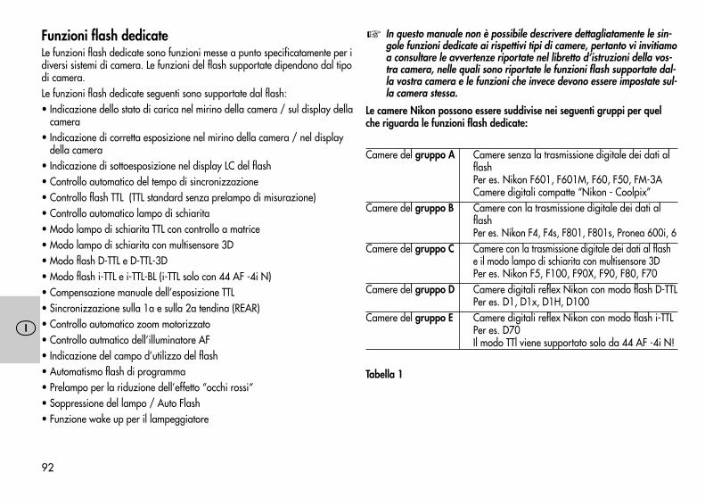
�
92
Funzioni flash dedicateLe funzioni flash dedicate sono funzioni messe a punto specificatamente per idiversi sistemi di camera. Le funzioni del flash supportate dipendono dal tipodi camera.Le funzioni flash dedicate seguenti sono supportate dal flash:• Indicazione dello stato di carica nel mirino della camera / sul display della
camera• Indicazione di corretta esposizione nel mirino della camera / nel display
della camera• Indicazione di sottoesposizione nel display LC del flash• Controllo automatico del tempo di sincronizzazione• Controllo flash TTL (TTL standard senza prelampo di misurazione)• Controllo automatico lampo di schiarita• Modo lampo di schiarita TTL con controllo a matrice• Modo lampo di schiarita con multisensore 3D• Modo flash D-TTL e D-TTL-3D• Modo flash i-TTL e i-TTL-BL (i-TTL solo con 44 AF -4i N)• Compensazione manuale dell’esposizione TTL• Sincronizzazione sulla 1a e sulla 2a tendina (REAR)• Controllo automatico zoom motorizzato• Controllo autmatico dell’illuminatore AF• Indicazione del campo d’utilizzo del flash• Automatismo flash di programma• Prelampo per la riduzione dell’effetto “occhi rossi“• Soppressione del lampo / Auto Flash• Funzione wake up per il lampeggiatore
In questo manuale non è possibile descrivere dettagliatamente le sin-gole funzioni dedicate ai rispettivi tipi di camere, pertanto vi invitiamoa consultare le avvertenze riportate nel libretto d’istruzioni della vos-tra camera, nelle quali sono riportate le funzioni flash supportate dal-la vostra camera e le funzioni che invece devono essere impostate sul-la camera stessa.
Le camere Nikon possono essere suddivise nei seguenti gruppi per quelche riguarda le funzioni flash dedicate:
Camere del gruppo A Camere senza la trasmissione digitale dei dati alflashPer es. Nikon F601, F601M, F60, F50, FM-3ACamere digitali compatte “Nikon - Coolpix”
Camere del gruppo B Camere con la trasmissione digitale dei dati alflashPer es. Nikon F4, F4s, F801, F801s, Pronea 600i, 6
Camere del gruppo C Camere con la trasmissione digitale dei dati al flashe il modo lampo di schiarita con multisensore 3DPer es. Nikon F5, F100, F90X, F90, F80, F70
Camere del gruppo D Camere digitali reflex Nikon con modo flash D-TTLPer es. D1, D1x, D1H, D100
Camere del gruppo E Camere digitali reflex Nikon con modo flash i-TTLPer es. D70Il modo TTl viene supportato solo da 44 AF -4i N!
Tabella 1
�
93
�
2. Preparazione del flash2.1 Montaggio del flash2.1.1 Montaggio del flash sulla camera
Spegnete la camera e il flash con l’interruttore principale!
• Ruotate il dado zigrinato fino ad arresto contro il flash. La spina di sicurezzanella base fino è ora scomparsa completamente nel corpo del flash.
• Spingete il flash con la base fino all’arresto nella slitta accessori della ca-mera.
• Ruotate il dado zigrinato fino ad arresto contro la camera e fissate il flash.Con fotocamere il cui corpo non possiede il foro per il blocco di sicurezza,il relativo perno, grazie al sistema a molla, scompare nel corpo del flashper non rovinare la superficie.
2.1.2 Smontaggio del flash dalla cameraSpegnete la camera e il flash con l’interruttore principale.
• Ruotate il dado zigrinato fino ad arresto contro il flash.• Estraete il flash dalla slitta accessori della camera.
2.2 Alimentazione2.2.1 Scelta delle pile o delle batterieIl flash può essere alimentato a scelta con:• 4 batterie al NiCd 1,2 V, tipo IEC KR 15/51 (KR6 / AA / Mignon), offro-
no il vantaggio di tempi di ricarica particolarmente brevi e un esercizioeconomico, in quanto ricaricabili.
• 4 batterie al nichel metallidruro 1,2 V, tipo HR6 (AA / Mignon); capacitànettamente superiore rispetto alle batterie NiCd e maggiore compatibilitàambientale, poiché privi di Cd.
• 4 batterie a secco alcaline al manganese 1,5 V, tipo IEC LR6 (AA /Mignon), una fonte di energia esente da manutenzione, adatta per unimpiego generico.
�
�
• 4 batterie al litio 1,5 V, tipo IEC FR6 L91 (AA / Mignon), una fonte d’ener-gía esente da manutenzione, ad elevata capacità e autoscarica contenuta.
Se prevedete di non usare il flash per lungo tempo, togliete le batteriedall’apparecchio.
2.2.2 Sostituizione delle batterie (Fig. 1)Le pile o le batterie sono vuote o esaurite, quando il tempo di ricarica (tempoche intercorre dall’emissione del lampo a piena potenza, ad es. con M, finoalla successiva accensione della spia di carica del flash) supera i 60 secondi.• Spegnete il flash con l’interruttore principale.• Spingete il coperchio vano batterie in direzione della freccia e apritelo.• Inserite le pile o le batterie NiCd in senso longitudinale come indicato dai
simboli delle batterie e chiudete il coperchio.Quando inserite le pile/batterie, assicuratevi sempre che le polarità(+/-) siano corrette, come indicato dai simboli all’interno del vanobatteria. L’inversione delle polarità può provocare la rottura dell’ap-parecchio!Sostituite sempre tutte le batterie con batterie equivalenti dello stessocostruttore e della stessa capacità!Non gettate mai le pile/batterie esaurite nei rifiuti domestici! Portatelenei contenitori appositi per il riciclaggio!
2.3 Accensione e spegnimento del flashIl flash si accende tramite l’interruttore principale sul coperchio del vano batteria.Quando l’interruttore è posizionato in alto su „ON“, il flash è acceso.Per spegnere il flash, spostate l’interruttore principale in basso.
Se prevedete di non utilizzare il lampeggiatore per lungo tempo, viconsigliamo di spegnere il lampeggiatore con l’interruttore principalee di estrarre le sorgenti di alimentazione (pile, batterie).
�
�
�
94
�
2.4 Spegnimento automatico dell’apparecchio / Auto - OFF (Fig. 2)Il flash è impostato di fabbrica in modo tale che circa 3 minuti• dopo l’accensione,• dopo l’emissione del lampo,• dopo aver premuto leggermente il pulsante di scatto della camera,• dopo lo spegnimento del sistema di misurazione dell’esposizione della
camera...... commuti su stand-by (Auto-OFF) per risparmiare energia ed evitare che lesorgenti d’alimentazione si scarichino inutilmente. La spia di carica del flash ele indicazioni sul display LC si spengono.La modalità d’esercizio impostata per ultimo rimane memorizzata dopo lospegnimento e viene immediatamente ripristimata alla successiva accensio-ne. Il lampeggiatore si riaccende non appena si premono i tasti „Mode“ o„Zoom“ oppure si tocca leggermente il pulsante di scatto della camera (fun-zione Wake-Up).
Se prevedete di non utilizzare il flash per lungo tempo, è opportunospegnere l’apparecchio sempre con l’interruttore principale!
Se lo si desidera, è possibile disattivare lo spegnimento automatico dell’ap-parecchio.Disattivazione dello spegnimento automatico dell’apparecchio• Accendete il flash con l’interruttore principale.• Premete la combinazione di tasti „Select“ (= tasto „Mode“ + tasto „Zoom“)
finché sul display LC non compare l’indicazione „3m“ (3 minuti).• Premete il tasto „Zoom“ finché sul display LC non lampeggia l’indicazione
„OFF“.• L’impostazione ha effetto immediato. Dopo circa 5 sec. il display LC ritorna
all’indicazione normale.
�
Attivazione dello spegnimento automatico dell’apparecchio• Accendete il flash con l’interruttore principale.• Premete la combinazione di tasti „Select“ (= tasto „Mode“ + tasto „Zoom“)
finché sul display LC non compare l’indicazione „3m“ (3 minuti).• Premete il tasto „Zoom“ finché sul display LC non lampeggia l’indicazione
„On“.• L’impostazione ha effetto immediato. Dopo circa 5 sec. il display LC ritorna
all’indicazione normale.
3. Automatismo di programma flash (flash completa-mento automatico)
Nell’automatismo di programma flash, la camera gestisce automaticamentel’apertura del diaframma, i tempi di posa e il flash, in modo tale che si otten-ga una ripresa ottimale il flash nelle maggiori situazioni di ripresa, anchenell’esercizio con lampo di schiarita.Impostazioni sulla cameraImpostate la camera sul modo Programma “P”, o sul Programma Scene oVari (paesaggio, ritratto, sport, ecc.). Selezionate sulla camera il modoAutofocus “Single-AF (S)”. Su alcune camere Nikon (ad es. F5, F65, F80,F100) si deve impostare sull’obiettivo sempre il numero di diaframma mag-giore (vedi istruzioni d’uso della camera).
Sui modelli di camera del Gruppo A (vedi Tabella 1) o in caso di im-piego di obiettivo privo di CPU (ossia senza trasferimento elettronicodi dati), adattate la posizione zoom della parabola manualmente allafocale dell’obiettivo (vedi 5.7.2)!
Nel “Programma riprese notturne” utilizzate uno stativo per evitareche la ripresa risulti mossa con tempi di posa lunghi!
�
�
95
�
Impostazione sul flashModo flash con camere del gruppo A, B e C (vedi Tabella 1):Impostate il flash nel modo “TTL” (vedi cap. 4.1).Con le camere del gurppo B si può impostare sul falsh, se necessario, ancheil modo lampo di schiarita con controllo a matrice (vedi cap. 4.1.2).Con le camere del gruppo C si può impostare sul flash, se necessario, ancheil modo lampo di schiarita con multisensore 3D (vedi 4.1.3).Modo flash con camere del gruppo D (vedi Tabella 1):Impostate il flash nel modo D-TTL o D-TTL-3D (vedi 4.2).Modo flash con camere del gruppo E (vedi Tabella 1):Impostate il flash nel modo i-TTL o i-TTL-BL (vedi 4.3)Il modo TTl viene supportato solo da 44AF -4i N.Appena avete effettuate le impostazioni suddette, potete iniziare a fare laripresa, se il flash è carico (vedi 5.1)!
4. Modalità del flash4.1 Modo flash TTL (Fig. 3)Con il modo flash TTL potete ottenere con facilità delle buone riprese. La misu-razione dell’esposizione nel Modo TTL viene effettuata da un sensore incorpo-rato nella camera. Questo sensore rileva l’intensità attraverso l’obiettivo (TTL =“Trough The Lens”). Non appena l’erogazione luminosa è sufficiente per unacorretta esposizione, il circuito di controllo elettronico della fotocamera trasmet-te al flash un segnale di stop che interrompe istantaneamente l’emissione dellampo. Questo tipo di funzionamento è vantaggioso poiché tiene conto, per laregolazione del lampo, automaticamente di tutti i fattori che influiscono sull’es-posizione, (presenza di filtri, variazioni di diaframma o di focale con obiettivizoom, l’uso di dispositivi di prolunga nelle riprese macro). Non dovete pre-occuparvi dell’impostazione del flash poiché il sistema elettronico della cameraprovvede automaticametne ad un corretto dosaggio del flash. Per il campod’utilizzo del flash osservate le indicazioni nel display LC del flash (vedi 5.4) ole avvertenze riportate nel capitolo 5.5. Se l’esposizione è corretta, sul display
LC del flash compare per circa 3 s l’indicazione “o.k.” (vedi 4.5).Il Modo flash TTL viene supportato da tutti i Modi della camera (ad es. Pro-gramma “P”, Automatismo dei tempi “A”, Automatismo del diaframma “S”,Programmi Scene o Vari, Manuale “M” ecc.).
Per testare il corretto funzionamento di TTL nella camera deve esserestata inserita una pellicola con camere analoghe! Fate attenzione alleeventuali limitazioni della vostra camera per quel che riguarda la sensi-bilità della pellicola o il valore ISO (ad es. massimo ISO 1000) per ilModo TTL (vedi istruzioni d’uso della camera)!Alcune camere digitali reflex non supportano il normale modo TTL stan-dard di camere analoghe. Se utilizzate il flash con camere del gruppo D(vedi Tabella 1) dovete impostare sul flash il modo D-TTL o D-TTL-3D(vedi cap. 4.2). Se utilizzate camere del gruppo E (vedi Tabella 1) dove-te impostare sul flash il modo i-TTL o i-TTL-BL(i-TTL solo con 44 AF -4i N, vedi capitolo 4.3)!
Procedura per l’impostazione del modo flash TTL• Montate il flash sulla camera.• Accendete il flash e la camera.• Premete il tasto “Mode” finché nel display LC non lampeggia il simbolo “TTL”.• L’impostazione ha effetto immediato. Dopo circa 5 sec. il display LC ritorna
all’indicazione normale.In presenza di contrasti molto forti, ad es. oggetto scuro sulla neve, potreb-be essere necessaria una compensazione dell’esposizione (vedi 4.4).
4.1.1 Lampi di schiarita automatici TTL con luce diurna (Fig. 5 e 6)Sulla maggior parte delle camere viene attivata, con la luce diurna, automa-ticamente la luce di schiarita nell’Automatismo di programma P e nei Pro-grammi Scene o Vari (vedi istruzioni d’uso della camera).La luce di schiarita consente di eliminare fastidiose ombre e nelle riprese incontroluce di raggiungere un’esposizione equilibrata tra motivo e sfondo. Unsistema di misurazione computerizzato della camera provvede ad una combi-nazione adeguata di tempi di posa, aperture di diaframma e potenza del flash.
�
�
96
�
Fate attenzione che la fonte del controluce non entri direttamentenell’obiettivo. Il sistema di misurazione TTL della camera non funzio-nerebbe correttamente!
In questo caso sul flash non ha luogo l’impostazione o l’indicazione per illampo di schiarita automatico TTL.
4.1.2 Modo lampo di schiarita TTL con controllo a matriceIn questa modalità l’illuminazione del motivo e dello sfondo vengono adatta-te automaticamente l’una all’altra, senza che il motivo risulti sovraesposto.L’impostazione dell’esposizione per la luce ambiente viene calcolata dallacamera con la misurazione a matrice.Diverse camere Nikon supportano il Modo lampo di schiarita TTL con con-trollo a matrice (vedi istruzioni d’uso della camera e Tabella 1).
Su alcune camere (ad es. F4, F4s) il modo lampo di schiarita TTL concontrollo a matrice non viene supportato con la misurazione dell’es-posizione SPOT. Questa modalità viene cancellata automaticamente onon si può attivare e viene impostato il normale modo TTL.
Con le camere del gruppo A (vedi Tabella 1) l’impostazione del modo lampodi schiarita TTL con controllo a matrice va effettuato sulla camera o vieneattivato automaticamente dalla camera (vedi istruzoini d’uso della camera).Sul flash non compare in questo caso alcuna indicazione né deve essere ef-fettuata alcuna impostazione.Con le camere del gruppo B (vedi Tabella 1) il modo lampo di schiarita TTLcon controllo a matrice va impostato e viene visualizzato sul flash:• Montate il flash sulla camera.• Accendete il flash e la camera.• Premete il pulsante di scatto della camera, in modo che tra il flash e la ca-
mera possa aver luogo uno scambio di dati.• Premete il tasto “Mode”, finchè sul display LC non lampeggia il simbolo
“TTL ”.
�
� • L’impostazione ha effetto immediato. Dopo circa 5 sec. il display LC ritornaall’indicazione normale.
Spegnimento del “Modo lampo di schiarita TTL con controllo a matrice”• Premete sul flash il tasto “Mode” finché sul display LC non lampeggia “TTL”
senza il simbolo .• L’impostazione ha effetto immediato. Dopo ca. 5s il display LC ritorna
all’indicazione normale.
4.1.3 Lampo di schiarita con multisensore 3DQuesto modo ottimizza l’equilibrio dell’esposizione tra motivo e sfondo.Nella ripresa viene emessa dal flash una serie di prelampi di misurazionequasi invisibili prima della vera e propria esposizione. Questa serie di pre-lampi viene analizzata dal multisensore TTL e dal microcontroller dellacamera. La camera adatta quindi l’esposizione flash TTL in modo ottimalealla situazione di ripresa (“Lampi di schiarita con multisensore”). Se si uti-lizzano “Obiettivi D-AF-Nikkor” viene presa in considerazione anche ladistanza dal motivo per determinare l’ottimale potenza del flash (“Lampi dischiarita con multisensore 3D”).Diverse camere del Gruppo C della Tabella 1 supportano il “Modo lampo dischiarita con multisensore 3D”.
Su alcune camere (ad es. F5, F80 e F100) il modo lampo di schiaritacon multisensore 3D non viene supportato con la misurazione dell’es-posizione SPOT. Questa modalità viene cancellata automaticamente onon si può attivare e viene impostato il normale modo TTL.
Impostazione del “Modo lampo di schiarita con multisensore 3D” sul flash• Montate il flash sulla camera.• Accendete flash e camera.• Premete leggermente il pulsante di scatto della camera, in modo che tra il
flash e la camera possa aver luogo uno scambio di dati.• Premete il tasto “Mode” finché sul display LC non lampeggia “TTL ”.
�
97
�
• L’impostazione ha effetto immediato. Dopo ca. 5s il display LC ritornaall’indicazione normale.
Impiegando un obiettivo privo di CPU su alcune camere viene suppor-tato solo il Modo lampo di schiarita con controllo a matrice o solo ilmodo flash TTL standard. In questo caso non si può impostare il modolampo di schiarita con multisensore 3D. Sul display LC del flash com-pare di conseguenza l’indicazione del modo flash attuale.
Disattivazione del modo “Lampi di schiarita con multisensore 3D”• Premete il tasto “Mode” sul flash finché sul display LC non lampeggia “TTL”
senza il simbolo .• L’impostazione ha effetto immediato. Dopo ca. 5s il display LC ritorna
all’indicazione normale.
4.2 Modo flash D-TTLQuesto modo è disponibile soltanto con le camere reflex digitaliNikon del gruppo D (vedi Tabella 1)! Il modo flash TTL standard dicamere analoghe non viene supportato dalle camere digitali reflex!
Il modo flash D-TTL è una versione più evoluta del modo flash TTL standarddi camere analoghe. Nella ripresa viene emessa dal flash una serie di pre-lampi di misurazione quasi invisibili prima della vera e propria esposizione.La luce riflessa dei prelampi viene valutata dalla camera e in base a suddettavalutazione, la camera adatta l’esposizione successiva in modo ottimale allasituazione di ripresa (vedi istruzioni d’uso della camera).Procedura per l’impostazione• Montate il flash sulla camera.• Accendete il flash e la camera.• Premete leggermente il pulsante di scatto della camera in modo che tra il
flash e la camera possa aver luogo uno scambio di dati.• Premete il tasto “Mode” finché sul display LC non lampeggia “D TTL”.• L’impostazione ha effetto immediato. Dopo circa 5 s il display LC ritorna
all’indicazione normale.
�
�
4.2.1 Modo flash D-TTL-3DIn questa caso la camera tiene conto nel modo flash D-TTL (vedi sopra) an-che dei dati sulla distanza dal motivo.
Questo modo è disponibile solo se si utilizzano “obiettivi AF Nikkortipo D”. Su alcune camere il modo flash D-TTL 3D non viene supporta-to con la misurazione dell’esposizione SPOT! Questa modalità vienecancellata automaticamente o non si può attivare e viene impostato ilnormale modo D-TTL.
Per impostare il modo flash D-TTL-3D la testa della parabola del flash devetrovarsi in posizione normale ovvero non deve essere orientata!Per il modo flash D-TTL-3D, la camera e l’obiettivo devono supportare la va-lutazione dei dati relativi alla distanza (vedi istruzioni d’uso della camera e idati tecnici dell’obiettivo)!Procedura per l’impostazione• Montate il flash sulla camera.• Accendete il flash e la camera.• Premete leggermente il pulsante di scatto della camera in modo che tra il
flash e la camera possa aver luogo uno scambio di dati.• Premete sul flash il tasto “MODE” finché sul display non lampeggiano
“D TTL” e il simbolo .• L’impostazione ha effetto immediato e viene memorizzata automaticamen-
te dopo 5 s.
4.3 Modo flash i-TTLQuesta modalità è disponibile solo con le camere reflex digitali Nikondel gruppo E (vedi tabella 1) e con 44 AF -4i N. Il modo flash TTLstandard di camere analoghe non viene supportato dalle cameredigitali reflex!
Il modo flash i-TTL è una una versione più evoluta del modo flash TTL stan-dard di camere analoghe Nella ripresa viene emessa dal flash una serie diprelampi di misurazione quasi invisibili prima della vera e propria esposizio-
�
�
98
�
ne. La luce riflessa dei prelampi viene valutata dalla camera e in base a sud-detta valutazione, la camera adatta l’esposizione successiva in modo ottima-le alla situazione di ripresa (vedi istruzioni d’uso della camera).Procedura per l’impostazione• Montate il flash sulla camera.• Accendete il flash e la camera.• Premete leggermente il pulsante di scatto della camera in modo che tra il
flash e la camera possa aver luogo uno scambio di dati.• Premete il tasto “Mode” sul flash finché sul display non lampeggia “TTL”.
Con le camere del gruppo E il modo flash i-TTL viene attivato automatica-mente sul flash. Il simbolo “i” non compare.
• L’impostazione ha effetto immediato e viene memorizzata automaticamen-te dopo 5 s.
4.3.1 Modo flash i-TTL-BLIn questa caso la camera tiene conto nel modo flash i-TTL (vedi sopra) anchedei dati sulla distanza dal motivo.
Questo modo è disponibile solo se si utilizzano “obiettivi AF Nikkortipo D”. Su alcune camere il modo flash i-TT-BL non viene supportatocon la misurazione dell’esposizione SPOT! Questa modalità vienecancellata automaticamente o non si può attivare e viene impostato ilnormale modo i-TTL.
Per il modo flash i-TTL-BL, la camera e l’obiettivo devono supportare la valu-tazione dei dati relativi alla distanza (vedi istruzioni d’uso della camera e idati tecnici dell’obiettivo)!Con la misurazione dell’esposizione SPOT, alcune camere supportano sol-tanto il modo flash i-TTL. Quindi non è possibile attivare il modo i-TTL-BL!Procedura per l’impostazione• Montate il flash sulla camera.• Accendete il flash e la camera.• Premete leggermente il pulsante di scatto della camera in modo che tra il
flash e la camera possa aver luogo uno scambio di dati.
�
• Premete il tasto “Mode” sul flash finché sul display non lampeggiano “TTL”e il simbolo . Il simbolo “i” non compare.
L’impostazione ha effetto immeditao e viene memorizzata automaticamentedopo 5 s.4.4 Compensazione manuale dell’esposizione TTLI sistemi di esposizione automatica flash TTL della maggior parte delle came-re sono regolati per un fattore di riflessione pari al 25 % (il fattore medio diriflessione per i motivi ripresi con flash). Uno sfondo scuro, che assorbe mol-ta luce, o uno chiaro che invece la riflette fortemente, possono causare unasottoesposizione o una sovraesposizione del motivo.Per correggere l’effetto descritto sopra, è possibile su alcune camere compen-sare l’esposizione flash TTL (o esposizione flash D-TTL / esposizione flashi–TTL con camere digitali reflex) manualmente selezionando un valore di com-pensazione in base alla situazione di ripresa. Il valore di compensazionedipende dal contrasto esistente tra il motivo e lo sfondo!
Motivo scuro davanti a sfondo chiaro: valore di compensazione positi-vo. Motivo chiaro davanti a sfondo scuro: valore di compensazionenegativo. Impostando il valore di compensazione, sul display LC delflash l’indicazione del campo d’utilizzo può variare in funzione delvalore impostato (a seconda del tipo di camera)!
Non è possibile correggere l’esposizione modificando l’apertura del dia-framma sull’obiettivo, in quanto il sistema di esposizione automatica dellacamera considererebbe il nuovo valore come il normale diaframma dilavoro.
Dopo la ripresa non dimenticate di azzerare sulla camera la compen-sazione dell’esposizione flash TTL!
A seconda del tipo di camera, l’impostazione per la compensazione manu-ale dell’esposizione TTL deve essere effettuata sulla camera o sul flash. Os-servate le avvertenze riportate nelle istruzioni d’uso della camera!Con le camere del gruppo A (vedi Tabella 1) l’impostazione deve essereeffettuata generalmente sulla camera ! L’impostazione sul flash non è quin-di possibile!
�
�
�
99
�
Impostazione sul flash• Montate il flash sulla camera.• Accendete il flash e la camera.• Premete il pulsante di scatto della camera, in modo che tra il flash e la ca-
mera possa aver luogo uno scambio di dati.• Premete la combinazione di tasti “Select” (= tasto “Mode” + tasto “Zoom”)
finché sul display LC non compare EV (Exposure Value = apertura di dia-framma). Accanto ad EV lampeggia il valore di compensazione impostato.
• Mentre il valore di compensazione lampeggia, potete impostare con iltasto “Zoom” un valore di compensazione positivo e con il tasto “Mode”un valore negativo.
Il campo di compensazione va da un valore di -3 a +1 in incrementi di 1/3.L’impostazione ha effetto immediato. Dopo ca. 5 s il display LC ritorna all’in-dicazione normale.Se la camera lavora con un obiettivo con CPU, sul display LC del flash lam-peggia EV accanto al simbolo del diaframma per segnalare che è stata effet-tuata una correzione manuale del valore per l’esposizione.Se la camere lavora senza obiettivo con CPU, sul display LC del flash com-pare come EV il valore di compensazione manuale impostato per l’esposizio-ne flash al posto del simbolo del diaframma e del valore di apertura del dia-framma. Al posto del campo di utilizzo viene visualizzato il numero guidaattuale del flash. Il campo d’utilizzo del flash può essere determinato utiliz-zando la formula riportata al capitolo 5.4.6.
Alcune camere offrono la possibilità di impostare un valore di com-pensazione manuale direttamente sulla camera. Con queste camere viconsigliamo di impostare il valore di compensazione o sulla camera osul flash.
Annullamento della compensazione manuale dell’esposizione flash TTL sul flash• Premete la combinazione di tasti “Select” (= tasto “Mode” + tasto “Zoom”)
finché sul display LC non compare EV.
�
• Accanto EV lampeggia il valore di compensazione impostato.• Mentre la visualizzazione del valore di compensazione lampeggia, con il
tasto “Zoom” o con il tasto “Mode” potete impostare il valore di compen-sazione su 0.0 e quindi annullarlo.
L’impostazione ha effetto immediato. Dopo ca. 5 s il display LC ritorna all’in-dicazione normale.
4.5 Indicazione di corretta esposizione nel Modo flash TTL (Fig. 4)L’indicazione di corretta esposizione “o.k.” compare nel display LC del flashsolo se la ripresa era correttamente esposta nel modo TTL o in un altro modopiù evoluto del modo TTL ( ad es. 3D-TTL, D-TTL, D-TTL-3D, i-TTL, i-TTL-BL ecc.)!Se, dopo la ripresa, non compare l’indicazione “o.k.” di corretta esposizione,ciò significa che la ripresa era sottoesposta e che quindi è necessario impostareil numero di daframma successivo inferiore (ad es. al posto di 11, il valore 8)oppure ridurre la distanza dal motivo o dalla superficie riflettente (ad es. conlampo riflesso) e ripetere la ripresa. Osservate l’indicazione del campo d’utilizzosul display LC del flash (vedi 5.4.1) oppure le avvertenze nel capitolo 5.5.
Per l’indicazione di corretta esposizione nel mirino della camera vedianche capitolo 5.3!
4.6 Indicazione di sottoesposizione nel Modo flash TTLIn diversi tipi di funzionamento della camera (ad es. con “P” e “A”) alcunecamere Nikon del Gruppo C, D e E della Tabella 1 segnalano un’eventualesottoesposizione della ripresa con flash in valori di diaframma (EV) sul dis-play LC del flash (vedi istruzioni d’uso della camera).Se dopo aver effettuato la ripresa con il flash, la spia di corretta esposizione“OK” sul flash non si accende e il simbolo flash nel mirino della camera lam-peggia, compare brevemente sul display LC del flash l’indicazione di sotto-esposizione da -0,3 a -3,0 in incrementi di 1/3 EV.In casi limite può accadere che sul flash non compare il simbolo “OK”, manel mirino della camera lampeggia il simbolo del flash. L’esposizione inquesti casi limite è tuttavia corretta!
�
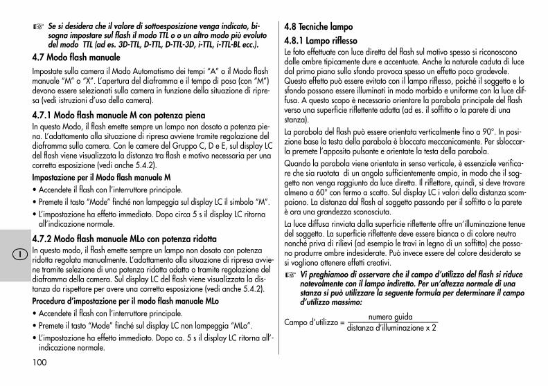
100
�
Se si desidera che il valore di sottoesposizione venga indicato, bi-sogna impostare sul flash il modo TTL o o un altro modo più evolutodel modo TTL (ad es. 3D-TTL, D-TTL, D-TTL-3D, i-TTL, i-TTL-BL ecc.).
4.7 Modo flash manualeImpostate sulla camera il Modo Automatismo dei tempi “A” o il Modo flashmanuale “M” o “X”. L’apertura del diaframma e il tempo di posa (con “M”)devono essere selezionati sulla camera in funzione della situazione di ripre-sa (vedi istruzioni d’uso della camera).
4.7.1 Modo flash manuale M con potenza pienaIn questo Modo, il flash emette sempre un lampo non dosato a potenza pie-na. L’adattamento alla situazione di ripresa avviene tramite regolazione deldiaframma sulla camera. Con le camere del Gruppo C, D e E, sul display LCdel flash viene visualizzata la distanza tra flash e motivo necessaria per unacorretta esposizione (vedi anche 5.4.2).Impostazione per il Modo flash manuale M• Accendete il flash con l’interruttore principale.• Premete il tasto “Mode” finché non lampeggia sul display LC il simbolo “M”.• L’impostazione ha effetto immediato. Dopo circa 5 s il display LC ritorna
all’indicazione normale.
4.7.2 Modo flash manuale MLo con potenza ridottaIn questo modo, il flash emette sempre un lampo non dosato con potenzaridotta regolata manualmente. L’adattamento alla situazione di ripresa avvie-ne tramite selezione di una potenza ridotta adatta o tramite regolazione deldiaframma della camera. Sul display LC del flash viene visualizzata la dis-tanza da rispettare per avere una corretta esposizione (vedi anche 5.4.2).Procedura d’impostazione per il modo flash manuale MLo• Accendete il flash con l’interruttore principale.• Premete il tasto “Mode” finché sul display LC non lampeggia “MLo”.• L’impostazione ha effetto immediato. Dopo ca. 5 s il display LC ritorna all’-
indicazione normale.
� 4.8 Tecniche lampo4.8.1 Lampo riflessoLe foto effettuate con luce diretta del flash sul motivo spesso si riconosconodalle ombre tipicamente dure e accentuate. Anche la naturale caduta di lucedal primo piano sullo sfondo provoca spesso un effetto poco gradevole.Questo effetto può essere evitato con il lampo riflesso, poiché il soggetto e losfondo possono essere illuminati in modo morbido e uniforme con la luce dif-fusa. A questo scopo è necessario orientare la parabola principale del flashverso una superficie riflettente adatta (ad es. il soffitto o la parete di unastanza).La parabola del flash può essere orientata verticalmente fino a 90°. In posi-zione base la testa della parabola è bloccata meccanicamente. Per sbloccar-la premete l’apposito pulsante e orientate la testa della parabola.Quando la parabola viene orientata in senso verticale, è essenziale verifica-re che sia ruotata di un angolo sufficientemente ampio, in modo che il sog-getto non venga raggiunto da luce diretta. Il riflettore, quindi, si deve trovarealmeno a 60° con fermo a scatto. Sul display LC i valori della distanza scom-paiono. La distanza dal flash al soggetto passando per il soffitto o la pareteè ora una grandezza sconosciuta.La luce diffusa rinviata dalla superficie riflettente offre un’illuminazione tenuedel soggetto. La superficie riflettente deve essere bianca o di colore neutrononché priva di rilievi (ad esempio le travi in legno di un soffitto) che posso-no produrre ombre indesiderate. Può invece essere del colore desiderato sesi vogliono ottenere effetti creativi.
Vi preghiamoo di osservare che il campo d’utilizzo del flash si riducenotevolmente con il lampo indiretto. Per un’altezza normale di unastanza si può utilizzare la seguente formula per determinare il campod’utilizzo massimo:
numero guidaCampo d’utilizzo = —————————————————
distanza d’illuminazione x 2
�
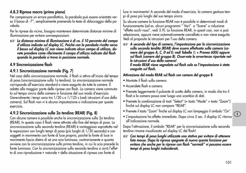
101
�
4.8.2 Riprese macro (primo piano)Per compensare un errore parallattico, la parabola può essere orientata ver-so il basso di -7°, semplicemente premendo la testa di sbloccaggio della pa-rabola.Per le riprese da vicino, bisogna mantenere determinate distanze minime diilluminazione per evitare sovraesposizioni.
La distanza minima di illuminazione è di ca. il 10 percento del campod’utilizzo indicato sul display LC. Poiché con la parabola rivolta versoil basso sul display LC non viene indicato alcun campo di utilizzo, do-vete prendere come riferimento il campo d’utilizzo indicato dal flashquando la parabola si trova in posizione normale.
4.9 Sincronizzazione flash4.9.1 Sincronizzazione normale (Fig. 7)Nel caso della sincronizzazione normale, il flash si attiva all’inizio del tempodi posa (sincronizzazione sulla 1a tendina). La sincronizzazione normalecorrisponde all’esercizio standard e viene eseguita da tutte le camere. Èadatta alla maggior parte delle riprese con flash. La camera viene commuta-ta sul tempo sincro della camera in funzione del suo modo d’esercizio.Generalmente i tempi sono tra 1/30 s e 1/125 s (vedi istruzioni d’uso dellacamera). Sul flash non vi è alcuna impostazione o indicazione per questoesercizio.
4.9.2 Sincronizzazione sulla 2a tendina (REAR) (Fig. 8)Con alcune camere è possibile anche la sincronizzazione sulla 2a tendina(REAR). In questo caso il flash viene attivato alla fine del tempo di posa. Lasincronizzazione sulla seconda tendina (REAR) è vantaggiosa soprattutto nel-le esposizioni con lunghi tempi di posa (più lunghi di 1/30 secondo) e consoggetti in movimento con fonte di luce propria, poiché la fonte di luce inmovimento lascia dietro di sé una scia luminosa, contrariamente a quantoavviene con la sincronizzazione sulla prima tendina, in cui la scia precede lafonte luminosa. Con la sincronizzazione sulla seconda tendina si avrà l’effet-to di una riproduzione « naturale » della situazione di ripresa con fonte di
�
luce in movimento! A seconda del modo d’esercizio, la camera gestisce tem-pi di posa più lunghi del suo tempo sincro.Su alcune camere la funzione REAR non è possibile in determinati modi difunzionamento (ad es. alcuni programmi “ Vari” o “Scene” o riduzione“effetto occhi rossi”, vedi 5.9). La funzione REAR, in questi casi, non si puòselezionare, oppure viene automaticamente cancellata o non viene eseguita.Vedi al proposito le istruzioni per l’uso della camera.
A seconda del tipo di camera, l’impostazione per la sincronizzazionesulla seconda tendita (REAR) deve essere effettuata sulla camera (ca-mere del gruppo A, C, D ed E; vedi Tabella 1; + Pronea 600i) oppuresul flash (camere del gruppo B). Osservate le avvertenze riportate nel-le istruzioni d’uso della camera!Il modo REAR viene segnalato sul flash solo se l’impostazione è stataeseguita sul flash.
Attivazione del modo REAR sul flash con camere del gruppo B• Montate il flash sulla camera.• Accendete flash e camera.• Premete leggermente il pulsante di scatto della camera, in modo che tra il
flash e la camera possa aver luogo uno scambio di dati.• Premete la combinazione di tasti “Select” (= tasto “Mode” + tasto “Zoom”)
finché sul display LC non compare “REAR”.• Premete il tasto “Zoom” finché sul display LC non lampeggia il simbolo “On”.• L’impostazione ha effetto immediato. Dopo circa 5 sec. il display LC ritorna
all’indicazione normale.Dopo l’attivazione, il simbolo “REAR” per la sincronizzazione sulla secondatendina rimane visualizzato sul display LC del flash!
Con tempi di posa lunghi utilizzate uno stativo per evitare di ottenerefoto mosse. Dopo la ripresa spegnete di nuovo questa funzione perevitare che anche per le riprese con flash “normali” vi possano esseretempi di posa lunghi indesiderati.
�
�
102
�
Disattivazione del modo REAR sul flash• Premete la combinazione di tasti “Select” (= tasto “Mode” + tasto “Zoom”)
finché sul display LC non compare “REAR”.• Premete il tasto “Zoom” finché sul display LC non lampeggia il simbolo
“OFF”.• L’impostazione ha effetto immediato. Dopo circa 5 sec. il display LC ritorna
all’indicazione normale.Il simbolo “REAR” per la sincronizzazione sulla seconda tendina scomparedal display del flash! Il flash si sincronizza quindi di nuovo sulla prima tendi-na (sincronizzazione normale).
4.9.3 Sincronizzazione con tempi lunghi / SLOWAlcune camere consentono, in determinati Modi, l’esercizio del flash con sin-cronizzazione con tempi lunghi “SLOW”. La sincronizzazione con tempilunghi consente di mettere più in luce lo sfondo in presenza di luminositàambiente scarsa. Ciò si ottiene adattando i tempo di posa della camera allaluce ambiente. In questo caso la camera imposta automaticamente tempi diposa più lunghi del tempo sincro della camera (ad es. tempi di posa fino a30 s). Su alcune camere la sincronizzazione con tempi lunghi viene attivataautomaticamente in determinati programmi della camera (ad es. programmiriprese notturne, ecc.) o può essere impostata sulla camera (vedi istruzionid’uso della camera). Sul flash non ha luogo alcuna impostazione o visualiz-zazione per questo modo.
Con tempi di posa lunghi utilizzate uno stativo per evitare che la fotovenga mossa!
�
5. Funzioni del flash e della camera5.1 Indicazione di stato di carica del flashQuando il condensatore flash è carico, sul flash si accende la spia di carica delflash per indicare che il flash è pronto. Ciò significa che per la prossima ri-presa si può utilizzare il flash. L’indicazione di flash carico viene trasmessa allacamera che presenta a sua volta il simbolo corrispondente nel mirino (vedi 5.3).Se la ripresa viene fatta prima che sul mirino compaia l’indicazione di flashcarico, il flash non viene attivato e la foto potrebbe avere un’esposizione noncorretta, nel caso in cui la camera abbia già commutato sul tempo sincro-flash(vedi 5.2).
5.2 Controllo automatico del tempo di sincronizzazioneA seconda del tipo e del Modo della camera, il tempo di posa viene commu-tato sul tempo sincro-flash, una volta che il flash ha raggiunto lo stato di ca-rica (vedi istruzioni d’uso della camera).Tempi di posa più brevi del tempo sincro-flash non possono essere impostatio vengono commutati sul tempo sincro-flash. Alcune camere dspongono diun tempo sincro che va, ad esempio, da 1/30 s a 1/125 s (vedi istruzionid’uso della camera). Il tempo sincro impostato dalla camera dipende dalModo della camera, dalla luce ambiente e dalla focale dell’obiettivo.Tempi di posa più lunghi del tempo sincro-flash possono essere impiegati aseconda del Modo della camera e della sincronizzazione flash selezionata(vedi anche 4.9.2 e 4.9.3).
Su alcune camere non ha luogo il controllo automatico del tempo disincronizzazione. Queste camere dispongono di un otturatore centraleche permette di lavorare con tutti i tempi di otturazione. Per ottenerela potenza piena del flash non selezionate tempi di otturazione piùbrevi di 1/125 s.
�
103
�
5.3 Indicazioni sul mirino della cameraIl simbolo flash verde si accendeRichiesta di utilizzo/accensione del flash.Il simbolo flash rosso si accendeIl flash è carico.Il simbolo flash rosso rimane acceso dopo la ripresa, oppure si spegnebrevementeL’esposizione della ripresa era corretta.Il simbolo flash rosso lampeggia dopo lo scattoLa ripresa era sottoesposta.
Per quel che riguarda le indicazioni nel mirino della camera, consulta-te nelle istruzioni d’uso della vostra camera ciò che vale per il vostrotipo di camera.
5.4 Indicazioni nel display LCLe camere Nikon del Gruppo B, C, D e E (vedi Tabella 1) trasmettono al flash idati relativi al ISO, alla focale dell’obiettivo (mm) e all’apertura del diafram-ma. Il flash adatta automaticamente le sue impostazioni a queste indicazioni ecalcola da questi dati e dal suo numero guida il campo massimo d’utilizzo delflash. Il modo flash, il campo d’utilizzo, il valore di diaframma e la posizionedella parabola zoom vengono visualizzati sul display LC del flash.Se azionate il flash senza che questo abbia ricevuto i dati dalla camera (ades. se la camera è spenta o quando si usano camere del Gruppo A), vengonovisualizzati solo il modo flash selezionato, la posizione della parabola e“M.Zoom”. Il valore di apertura del diaframma e il campo d’utilizzo vengonovisualizzati solo se il flash ha ricevuto i necessari dati dalla camera.
Auto Zoom, apertura di diaframma e campo d’utilizzo vengono indi-cati solo con camere del Gruppo B, C, D e E (vedi Tabella 1), soltantose queste utilizzano obiettivi AF o obiettivi con CPU!
�
�
5.4.1 Indicazione campo d’utilizzo nel modo TTLSul display LC del flash viene visualizzato il valore del massimo campo d’utiliz-zo del flash. Il valore visualizzato si riferisce ad un grado di riflessione del25 % del motivo: cosa che interessa la maggior parte delle situazioni di ripre-sa. Scostamenti elevati del grado di riflessione, ad es. in presenza di oggettimolto o poco riflettenti, possono influenzare il campo d’utilizzo del flash.Osservate durante la ripresa l’indicazione del campo d’utilizzo sul displayLC del flash. Il motivo dovrebbe trovarsi in un campo compreso tra circa il40 % e il 70 % del valore visualizzato. Ciò consente all’elettronica di avereun gioco sufficiente per la compensazione. La distanza minima dal motivonon dovrebbe essere inferiore al 10 % del valore indicato per evitare sovra-esposizioni. L’adattamento alle diverse situazioni di ripresa è possibile vari-ando l’apertura del diaframma sull’obiettivo.
5.4.2 Indicazione del campo d’utilizzo nel Modo manuale M o MLoNel display LC del flash viene visualizzata la distanza necessaria per una cor-retta esposizione del motivo. L’adattamento alle diverse situazioni di ripresa èpossibile modificando l’apertura del diaframma sull’obiettivo e selezionandouna potenza piena M o una potenza parziale MLo (vedi 4.7).
5.4.3 Superamento del campo indicatoIl flash può visualizzare campi d’utilizzo massimi di 199 m/199 ft. Con valoriISO elevati (ad es. ISO 6400) e ampie aperture del diaframma è possibile su-perare il campo d’indicazione visualizzabile. Ciò viene indicato con una frec-cia o un triangolo dietro all’indicazione della distanza.
5.4.4 Soppressione dell’indicazione del campo d’utilizzoOrientando verso l’alto o verso il basso la testa della parabola, la distanzanon viene indicata sul display LC del flash!
104
�
5.4.5 Segnalazione di errore “FEE” sul display LC del flashSu determinate camere o in certi modi di funzionamento della camera (ades. Programma P, Programmi Vari, Automatismo di diaframma S) è necessa-rio impostare sull’obiettivo la ghiera dei diaframmi sul numero di diaframmamassimo (= apertura minima). Se la ghiera dei diaframmi non si trova sulnumero di diaframma massimo, compare sul display LC del flash o sullacamera l’indicazione di errore “FEE”! Controllate in questo caso le impos-tazioni di camera e obiettivo (vedi istruzioni d’uso della camera).
5.4.6 Indicazione numero guida con obiettivo con messa a fuoco manualeGli obiettivi privi di CPU (ossia senza trasferimento elettronico dei dati) non tras-mettono alla camera le informazioni elettriche relative alla distanza focale ne all’-apertura del diaframma. Se un tale obiettivo viene impiegato su camere del grup-po B, C, D e E, il flash riceve dalla camera solo i dati relativi al ISO. La posizionedella parabola zoom deve essere impostata manualmente (vedi 5.7.2).Con alcune camere compare sul display LC del flash, in questo caso, al postodel valore della distanza il numero guida per l’impostazione del momento. Ilcampo massimo di utilizzo del flash si ricava da questa formula:
numero guidaCampo d’utilizzo = —————————
diaframma
Vi preghiamo di tenere presente le avvertenze sulla distanza dal moti-vo al capitolo 5.5! Se la parabola è orientata il numero guida nonviene visualizzato!
5.4.7 Commutazione metri - piedi (m - ft)Il campo d’utilizzo può essere visualizzato sul display LC del flash a scelta inmetri (m) o in piedi (ft). Per commutare l’indicazione procedere come descrit-to qui di seguito:• Spegnete il flash con l’interruttore principale.• Tenete premuta la combinazione di tasti “Select” (= tasto “Mode” + tasto
“Zoom”).• Accendete il flash con l’interruttore principale.
�
• Rilasciate la combinazione di tasti “Select” (= tasto “Mode” + tasto“Zoom”).
• L’indicazione della distanza commuta da m ad ft, oppure da ft ad m.
5.5 Determinazione del campo d’utilizzo tramite la tabella deinumeri guida
Le camere del Gruppo A non trasmettono al flash i dati relativi alla sensibili-tà ISO, al diaframma e alla focale. L’apertura di diaframma impostata sullacamera e il campo d’utilizzo del flash non compaiono sul display LC delflash. In questo caso potete determinare il campo d’utilizzo del flash serven-dovi della Tabella 2 riportata in allegato (vedi 10).Vale la seguente formula:
numero guidaCampo d’utilizzo = —————————
diaframma
Ciò non vale per l’esposizione flash indiretta, ad es. con la parabolaflash orientata!
Esempio:Utilizzate ISO 100 e una distanza focale dell’obiettivo di 50 mm. Dalla Ta-bella 2 riportata in allegato riportata in allegato ricaverete il numero gui-da 34 valido per questa combinazione. Sulla camera o sull’obiettivo selezio-nate ad esempio il diaframma 4. Con la formula suddetta potete ricavareora il campo d’utilizzo del flash:
numero guida 34Campo d’utilizzo = ——————————— = 8,5 m
diaframma 4
Nel Modo flash manuale M con potenza piena ciò significa che il soggetto sidovrebbe trovare ad una distanza di 8,5 m per ottenere una corretta esposi-zione.Nel Modo flash TTL ciò significa che il soggetto può trovarsi al massimo ad unadistanza di 8,5 m. Per lasciare tuttavia all’elettronica dell’automatismo di espo-sizione nella camera gioco sufficiente per la regolazione della luce, il soggetto
�
105
�
dovrebbe trovarsi ad una distanza compresa tra il 40 % e il 60 % del campod’utilizzo ricavato dal calcolo. Nell’esempio suddetto ciò corrisponderebbe aduna distanza compresa tra 3,4 m e 5,1 m. Per evitare sovraesposizioni nelleriprese macro si tenga presente che si deve mantenere una distanza minima del10 % del valore ricavato. Nell’esempio suddetto, la distanza minima del 10 %di 8,5 m = 0,85 m.
Vi preghiamo di osservare che il campo d’utilizzo si riferisce a motivicon un grado di riflessione del 25 %: come accade nella maggior par-te delle situazioni di ripresa. Gradi di riflessione molto divergenti, adesempio con motivi poco riflettenti o con un fortissimo grado di rifles-sione, possono influire sul campo d’utilizzo del flash.
5.6 Illuminazione display LCPremendo il tasto “Mode” oppure il tasto “Zoom” si attiva per circa 10 s l’il-luminazione del display LC del flash. Con l’attivazione del lampo l’illumina-zione del display LC si spegne.
Azionando per la prima volta i suddetti tasti non ha luogo alcuna va-riazione delle impostazioni sul flash!
Se nel Modo TTL l’esposizione è corretta, l’illuminazione del display LC vieneattivata durante la visualizzazione del simbolo “o.k.” (vedi 4.5).
5.7 Parabola zoom motorizzataLa parabola del flash può illuminare focali di obiettivo a partire da 24 mm.5.7.1 “Auto-Zoom”Se si impiega il flash in combinazione con una camera del Gruppo B, C, D eE e un obiettivo con CPU, la posizione della sua parabola zoom viene adat-tata automaticamente alla focale dell’obiettivo. Dopo aver acceso il flash, suldisplay LC dello stesso compare “Auto Zoom” e l’attuale posizione della pa-rabola.L’adattamento automatico della parabola ha luogo per focali d’obiettivo apartire da 24 mm. Se si impiega una focale inferiore a 24 mm, sul displayLC il simbolo “24” mm comincia a lampeggiare per indicare che la ripresanon può essere illuminata ai bordi completamente dal flash.
�
�
Per obiettivi con focali a partire da 20 mm si può utilizzare un diffu-sore grandangolare (accessori opzionali, vedi cap. 7). La parabolaflash deve trovarsi in posizione 24 mm.
5.7.2 Modo zoom manuale “M. Zoom”Con camere del Gruppo A o con un obiettivo privo di CPU (ad es. obiettivocon messa a fuoco manuale), la posizione della parabola zoom deve essereadattata maualmente alla focale dell’obiettivo. Il Modo Auto-Zoom non è inquesto caso possibile! Nel display LC del flash compare “M.Zoom” (per l’im-postazione zoom manuale) e la posizione attuale zoom (mm).• Premendo ripetutamente il tasto “Zoom” sul flash si possono selezionare
una dopo l’altra le seguenti posizioni per la parabola:24 mm - 28 mm - 35 mm - 50 mm - 70 mm - 85 mm - 105 mm.Un’impostazione errata della posizione della parabola zoom non è seguitada alcuna segnalazione di avvertimento!
Se non utilizzare sempre il numero guida e il campo d’utilizzo massi-mi del flash, potete lasciate la parabola zoom sulla posizione corris-pondente alla focale iniziale dell’obiettivo zoom. Ciò assicura sempreun’illuminazione completa dei bordi. In tal modo non dovrete efettua-re il continuo adattamento alla focale variabile dell’obiettivo.
Esempio:Utilizzate un obiettivo zoom con una focale che va da 35 mm a 105 mm. Inquesto caso impostate la posizione della parabola zoom del flash su 35 mm.
5.7.3 Modo zoom manuale anziché “Auto-Zoom”Se lo si desidera, con camere del Gruppo B, C, D e E e obiettivi con CPU èpossibile impostare la posizione della parabola zoom manualmente perpoter ottenere determinati effetti di illuminazione (ad es. hot-spot ecc.).Premendo ripetutamente il tasto “Zoom” sul flash si possono selezionare unadopo l’altra le seguenti posizioni per la parabola:24 mm - 28 mm - 35 mm - 50 mm - 70 mm - 85 mm - 105 mm.Nel display LC del flash compaiono il simbolo “M.Zoom” (per impostazioni
�
�
106
�
manuali dello zoom) e la posizione zoom attuale (mm). L’impostazione haeffetto immediato. Dopo circa 5 s il display LC ritorna all’indicazione normale.
Se la regolazione manuale della parabola zoom provoca una illumi-nazione incompleta dell’immagine ai bordi, l’indicazione della posi-zione della parabola comincia a lampeggiare sul display del flashcome segnale di avvertimento.
Esempio:• Lavorate con focale obiettivo 50 mm.• Sul flash la parabola è posizionata manualmente su 70 mm (indicazione
“M.Zoom”).• Sul display LC del flash l’indicazione “70” mm per la posizione zoom lam-
peggia poiché i bordi dell’immagine non possono essere illuminati comple-tamente.
Reset su “Auto-Zoom”Per risettare su “Auto Zoom” esistono diverse possibilità:• premete il tasto “Zoom” sul flash finché sul display non compare “Auto
Zoom”. L’impostazione ha effetto immediato. Dopo circa 5 s il display LCritorna all’indicazione normale.
oppure:• spegnete brevemente il flash con l’interruttore principale. Una volta riacce-
so, sul display del flash compare “Auto Zoom”.
5.7.4 Modo “Zoom esteso”Con il modo Zoom esteso (Ex) la focale del flash viene ridotta di un gradorispetto alla focale dell’obiettivo della camera! Ciò provoca l’illuminazione diuna superficie maggiore provvedendo, in ambienti chiusi, ad una supplemen-tare luce diffusa (riflessioni) e quindi ad una più morbida illuminazione dellaluce flash.
Esempio per il modo Zoom esteso:La focale dell’obiettivo sulla camera è di 35 mm. Nel Modo Zoom esteso ilflash imposta la posizione della parabola su 28 mm. Sul display LC continua
�
tuttavia ad essere visualizzato 35 mm!Il modo “Zoom esteso” è possibile solo nel modo “Auto Zoom” con cameredel Gruppo B, C, D e E della Tabella 1 e con obiettivi CPU con focali a parti-re da 28 mm.Poiché la posizione iniziale della parabola è di 24 mm, con focali inferiori a 28 mmsul display LC lampeggia “24” mm. Ciò sta a significare che non può essere realizza-ta la posizione della parabola necessaria per il modo “Zoom esteso”.
Riprese con focali dell’obiettivo che vanno da 24 mm vengono illumi-nate correttamente dal flash anche nel modo Zoom esteso!
Accensione del Modo «Zoom esteso• Premete la combinazione di tasti “Select” (= tasto “Mode” + tasto “Zoom”)
finché sul display LC non compare “Ex”.• Premete il tasto “Zoom” finché sul display LC non lampeggia il simbolo
“On”.• L’impostazione ha effetto immediato. Dopo circa 5 sec. il display LC ritorna
all’indicazione normale.Il simbolo “Ex” per il Modo Zoom esteso rimane visualizzato dopo l’imposta-zione sul display LC del flash!
Tenete presente che un’illuminazione più ampia nel Modo Zoom este-so determina un campo d’utilizzo del flash ridotto!
Spegnimento del Modo Zoom esteso• Premete la combinazione di tasti “Select” (= tasto “Mode” + tasto “Zoom”)
finché sul display LC non compare il simbolo “Ex”.• Premete il tasto “Zoom” finché sul display LC non lampeggia il simbolo
“Off”.• L’impostazione ha effetto immediato. Dopo circa 5 sec. il display LC ritorna
all’indicazione normale..Il simbolo “Ex” per il Modo Zoom esteso non viene più visualizzato sul dis-play LC del flash!
�
�
107
�
5.8 Illuminatore di assistenza AFNon appena la luce ambiente non è più sufficiente per una messa a fuoco au-tomatica, il sistema elettronico della camera attiva l’illuminatore AF (Autofo-cus). Il proiettore autofocus proietta un fascio di raggi luminosi sul motivo, lacui riflessione consente alla camera di operare la messa a fuoco. La portatadell’illuminatore AF è di circa 6 m ... 9 m (con obiettivi standard 1,7/50 mm).A causa del parallasse tra obiettivo e proiettore AF a luce rossa il limite dellamessa a fuoco ravvicinata dell’illuminatore AF va da circa 0,7 m a 1 m.
Perché l’illuminatore AF possa essere attivato dalla camera, la came-ra deve essere impostata su AF “Single-AF (S)” (vedi istruzioni d’usodella camera). Obiettivi zoom con apertura ridotta del diaframmainiziale limitano a volte considerevolmente la portata dell’illuminato-re AF!Il fascio luminoso dell’illuminatore AF supporta solo il sensore centraleAF della camera. Con camere dotate di diversi sensori AF vi raccom-andiamo di attivare solo il campo di misurazione AF centrale della ca-mera (vedi istruzioni d’uso della camera).Se viene selezionato un sensore AF decentrato dal fotografo stesso oautomaticamente dalla camera, la parabola per l’illuminatore AF delflash non viene attivata.Alcune camere utilizzano in questo caso la parabola integrata nellacamera per l’illuminatore AF (vedi le istruzioni d’uso della camera).
�
5.9 Prelampi contro l’effetto “occhi rossi” (Red-Eye-Reduction)Gli “occhi rossi” sono un effetto puramento fisico. Questo effetto si presentaquando la persona da fotografare guarda più o meno direttamente la came-ra, la luce ambiente è relativamente bassa e il lampeggiatore è montato di-rettamente sulla camera o si trova nelle sue immediate vicinanze. Il lam-peggiatore schiarisce in questi casi il fondo dell’occhio, per cui la retina(iniettata di sangue) diventa visibile attraverso la pupilla e viene registratadalla camera sotto forma di macchia o punto rosso.
La funzione di riduzione dell’effetto “occhi rossi” (Red-Eye-Reduction) ha unsensibile effetto positivo. Con questa funzione il flash accende tre prelampitenui visibili ai quali segue il lampo principale prima dell’apertura della 1atendina. I tre prelampi provocano un ulteriore restringimento delle pupille, avantaggio di una riduzione dell’effetto “occhi rossi”.
La funzione di prelampo viene impostata sulla camera. Quando è attiva, com-pare sul display LC della camera il relativo simbolo (vedi istruzioni d’uso dellacamera)! Sul flash non vi è alcuna impostazione né indicazione per questafunzione.La funzione di prelampo per la riduzione dell’effetto “occhi rossi” è possibilesolo con camere che supportano tale funzione (vedi istruzioni d’uso della ca-mera)!Su alcune camere la riduzione dell’effetto “occhi rossi” supporta solo il flashincorporato nella camera o un illuminatore speciale integrato nel corpo dellacamera (vedi istruzioni d’uso della camera)!Utilizzando la funzione prelampo, la sincronizzazione sulla 2a tendina(REAR) non è possibile!
108
�
5.10 Flash automatico/ Soppressione del lampo (AUTO-FLASH)Se la luce ambiente è sufficiente per una corretta esposizione nel modo nor-male, determinate camere impediscono l’attivazione del flash e pertanto pre-mendo il pulsante di scatto della camera non viene emesso alcun lampo. Lasoppressione del lampo funziona su alcune camere solo nel modo pro-gramma completamente automatico o programma “P” oppure deve essereattivata sulla camera (vedi istruzioni d’uso della camera).
5.11 Ritorno all’impostazione inizale (reset)Il flash può essere riportato all’impostazione inizale tenendo premuto il tasto“Mode” per almeno 3 secondi.Le impostazioni seguenti vengono attivate:• Modo flash “TTL”.• Spegnimento automatico dell’apparecchio “Auto-Off” (3m On).• Modo Automatico Zoom “Auto-Zoom”.• Cancellazione del Modo Zoom esteso “Ex”.• Il valore di compensazione dell’esposizione flash sul flash viene cancellato.• L’impostazione REAR sul flash viene annullata.
6. Avvertenze speciali della cameraVista la varietà di modelli di camera e delle loro caratteristiche non possia-mo trattare in questa sede in modo dettagliato tutte le possibilità, impostazio-ni, indicazioni ecc. specifiche per ogni camera. Le informazioni e le avver-tenze circa l’impiego di un flash sono raccolte nelle istruzioni d’uso dellavostra camera al capitolo rispettivo!
6.1 Funzioni speciali non supportate nel Modo flash6.1.1 Spostamento di programma / Programm-ShiftCon il flash accesso, lo spostamento di programma (coppia tempo-diaframma)con alcune camere non può essere eseguito nell’Automatismo di programma P(vedi istruzioni d’uso della camera).
109
�
7. Accessori opzionaliIl cattivo funzionamento e i danni eventualmente provocati al flashdall’utilizzo di accessori di altre marche non sono coperti dalla nostragaranzia!
• Diffusore grandangolare 20mm(art. N° 000044217)Per l’illuminazione di focali di obiettivi a partire da 24 mm. I valori di porta-ta limite si riducono in funzione della perdita di luce di circa il fattore 1,4.
• Set filtro colorati 44-32(art. N° 00004432A)Comprende 4 filtri a colori per illuminazioni d’effetto e un filtro trasparenteper la ripresa di pellicole colorate di qualsiasi colore.
• Mecabounce 44-90(art. N° 000044900)Questo diffusore permette di realizzare con estrema semplicità un’illumina-zione tenue. L’effetto che se ne ricava è straordinario poiché crea un’im-magine morbida. Il colore della pelle del viso risulta molto naturale. I valoridi portata limite si riducono della metà in funzione alla perdita di luce.
• Schermo riflettente 54-23(art. N° 000054236)riflette una luce diffusa per ammorbidire le ombre.
�8. In caso di anomalie di funzionamentoNel caso il cui il display LC del flash dovesse per esempio fornire indicazionisenza senso o il flash non funzionasse come dovrebbe, spegnete il flash percirca 10 secondi con l’interruttore principale. Controllate che la base delflash sia stata montata correttamente nella slitta portaccessori della camera everificare le impostazioni della camera.Dopo la riaccensione, il flash dovrebbe funzionare di nuovo “normalmente”. Incaso contrario vi preghiamo di rivolgersi al rivenditore specializzato.
9. Cura e manutenzioneEliminate lo sporco e la polvere con un panno morbido, asciutto o trattato alsilicone. Non utilizzate prodotti detergenti, in quanto potrebbero provocaredanni alle parti in plastica.Formazione del condensatore flashIl condensatore incorporato nel flash tende a deformarsi qundo il lampeggia-tore resta inutilizzato per lungo tempo. Per questo è necessario accendereper circa 10 min. l’apparecchio ogni tre mesi (vedi al proposito 2.4). Se lebatterie hanno energia sufficiente, la spia di carica flash impiega non più diun minuto per accendersi.
110
�
10. Dati tecniciNumero guida massimo per ISO 100 / 21°; Zoom 105 mm:in metri: 44 in piedi: 144Durata del lampo:ca. 1/200 ... 1/20.000 secondi (nel Modo TTL)nel Modo M ca. 1/200 secondi a potenza pienanel Modo MLo ca. 1/5000 secondi
Temperatura di colore:ca. 5600 K
Sensibilità della pellicola:da ISO 6 a ISO 6400
Sincronizzazione:accensione a bassa tensione
Numero lampi:ca. 85 con batterie NiCd (600 mAh)ca. 205 con batterie al nichel metallidruro (1600 mAh)ca. 240 con batterie alcaline al manganese di elevata capacità(rispettivamente a piena potenza)
Tempo di ricarica:ca. 4 s con batterie NiCdca. 4 s con batterie al nichel metallidruroca. 5 s con batterie alcaline al manganese di elevata capacità(rispettivamente a piena potenza)
Orientabilità e posizioni di arresto della testa della parabola:verso l’alto / verso il basso: 60°, 75°, 90° / -7°Dimensioni in mm (ca.):75 x 125 x 108 (larg x alt x prof)Peso:flash con batterie: ca. 400 grammiDotazione standard:lampeggiatore, istruzioni d’uso
Smaltimento delle batterieLe batterie non vanno gettate insieme ai rifiuti domestici.Si prega di utilizzare un sistema di smaltimento adeguato, p. es. portandoleal negozio dove le si è acquistate o ad un centro di raccolta apposito.Si prega di effettuare lo smaltimento soltanto di batterie scariche.Le batterie sono scariche, quando l’apparecchio, alimentato dalle stesse,- si spegne e segnala „batteria vuota“- non funziona regolarmente dopo un uso prolungato delle batterie.Per una protezione contro il cortocircuito si consiglia di coprire i poli dellabatteria con del nastro autoadesivo.
Riserva di modifiche e disponibilità di fornitura!

111
�
✍ ✍
112
�
1. Indicaciones de seguridad . . . . . . . . . . . . . . . . . . . . . . . . . . . 113Tabla 1 . . . . . . . . . . . . . . . . . . . . . . . . . . . . . . . . . . . . . . . . . 114
2. Preparación del flash . . . . . . . . . . . . . . . . . . . . . . . . . . . . . . . 1152.1 Montaje del flash . . . . . . . . . . . . . . . . . . . . . . . . . . . . . . . . . . 1152.1.1 Montar el flash sobre la cámara . . . . . . . . . . . . . . . . . . . . . . . 1152.1.2 Extraer el flash de la cámara . . . . . . . . . . . . . . . . . . . . . . . . . . 1152.2 Alimentación de corriente . . . . . . . . . . . . . . . . . . . . . . . . . . . . 1152.2.1 Selección de pilas o acumuladores. . . . . . . . . . . . . . . . . . . . . . 1152.2.2 Cambio de las pilas . . . . . . . . . . . . . . . . . . . . . . . . . . . . . . . . 1152.3 Conexión y desconexión del flash . . . . . . . . . . . . . . . . . . . . . . 1152.4 Desconexión automática del flash /Auto - OFF . . . . . . . . . . . . . 1163. Automatismo progr. para flash (automatismo total del flash) . . 1164. Modos de funcionamiento del flash. . . . . . . . . . . . . . . . . . . . . 1174.1 Funcionamiento TTL del flash . . . . . . . . . . . . . . . . . . . . . . . . . . 1174.1.1 Destello de aclaración TTL automático, con luz de día . . . . . . . . 1184.1.2 Control matricial del destello de aclaración TTL . . . . . . . . . . . . . 1184.1.3 Funcionamiento de destellos de aclaración por multisensor 3D. . 1184.2 Control del flash D-TTL . . . . . . . . . . . . . . . . . . . . . . . . . . . . . . 1194.2.1 Control del flash D-TTL-3D. . . . . . . . . . . . . . . . . . . . . . . . . . . . 1194.3 Control del flash i-TTL . . . . . . . . . . . . . . . . . . . . . . . . . . . . . . . 1204.3.1 Control del flash i-TTL-BL . . . . . . . . . . . . . . . . . . . . . . . . . . . . . 1204.4 Corrección manual de exposición del flash TTL . . . . . . . . . . . . . 1204.5 Indicador del control de la exposición en funcionamiento TTL . . . 1224.6 Indicación de subexposición en funcionamiento TTL del flash . . . 1224.7 Funcionamiento manual del flash . . . . . . . . . . . . . . . . . . . . . . . 1224.7.1 Funcionamiento manual M del flash con plena potencia luminosa . 1224.7.2 Modo manual del flash MLo con potencias parciales de luz . . . . . . . 1224.8 Técnicas de destello . . . . . . . . . . . . . . . . . . . . . . . . . . . . . . . . 1234.8.1 Destellos indirectos . . . . . . . . . . . . . . . . . . . . . . . . . . . . . . . . . 1234.8.2 Fotografía de proximidad / primeros planos . . . . . . . . . . . . . . 1234.9 Sincronización del flash . . . . . . . . . . . . . . . . . . . . . . . . . . . . . 1234.9.1 Sincronización normal . . . . . . . . . . . . . . . . . . . . . . . . . . . . . . 1234.9.2 Sincronización a la 2ª cortinilla (modo REAR). . . . . . . . . . . . . . 123
4.9.3 Sincronización de velocidad lenta / SLOW . . . . . . . . . . . . . . . 1245. Funciones de la cámara y del flash . . . . . . . . . . . . . . . . . . . . . 1255.1 Indicación de disposición de disparo . . . . . . . . . . . . . . . . . . . . 1255.2 Control automático de sincronización del flash . . . . . . . . . . . . . 1255.3 Indicadores en el visor de la cámara . . . . . . . . . . . . . . . . . . . . 1255.4 Indicadores en el display LC . . . . . . . . . . . . . . . . . . . . . . . . . . 1255.4.1 Indicador del alcance en funcionamiento TTL del flash . . . . . . . . 1265.4.2 Indicador del alcance en funcionam. manual del flash M, respect. MLo . 1265.4.3 Superación del margen de indicación . . . . . . . . . . . . . . . . . . . 1265.4.4 Desaparición del indicador del alcance . . . . . . . . . . . . . . . . . . 1265.4.5 Indicador de error “FEE” en el display LC del flash . . . . . . . . . . 1265.4.6 Indicador del número - guía con objetivos sin CPU . . . . . . . . . . 1265.4.7 Conmutación de metros a pies (m - ft) . . . . . . . . . . . . . . . . . . . 1265.5 Determinación del alcance del destello con la tabla de números - guía. 1275.6 Iluminación del display LC . . . . . . . . . . . . . . . . . . . . . . . . . . . . 1285.7 Reflector con motor zoom . . . . . . . . . . . . . . . . . . . . . . . . . . . . 1285.7.1 “Auto-Zoom” . . . . . . . . . . . . . . . . . . . . . . . . . . . . . . . . . . . . . 1285.7.2 Funcionamiento zoom manual “M. Zoom” . . . . . . . . . . . . . . . . 1285.7.3 Funcionamiento zoom manual, en lugar de “Auto-Zoom” . . . . . 1285.7.4 Funcionamiento del zoom extendido . . . . . . . . . . . . . . . . . . . . 1285.8 Destello de medición autofoco . . . . . . . . . . . . . . . . . . . . . . . . . 1295.9 Predestellos contra el “Efecto de ojos rojos” (Red-Eye-Reduction) 1305.10 Flash automátiqo / control de ignición (AUTO-FLASH) . . . . . . . 1305.11 Retorno a los ajustes básicos . . . . . . . . . . . . . . . . . . . . . . . . . . 1306. Indicaciones especiales para la cámara . . . . . . . . . . . . . . . . . 1316.1 Funciones especiales no soportadas en modo flash . . . . . . . . . . 1316.1.1 Desplazamiento de programa / Programm-Shift . . . . . . . . . . . . 1317. Accesorios especiales . . . . . . . . . . . . . . . . . . . . . . . . . . . . . . . 1318. Ayuda en caso de problemas . . . . . . . . . . . . . . . . . . . . . . . . . 1329. Mantenimiento y cuidados . . . . . . . . . . . . . . . . . . . . . . . . . . . 13210. Características técnicas. . . . . . . . . . . . . . . . . . . . . . . . . . . . . . 133
Tabla 2. . . . . . . . . . . . . . . . . . . . . . . . . . . . . . . . . . . . . . . . . . 134
�
113
�
IntroducciónLe agradecemos que se haya decidido por un producto de Metz y nos com-place saludarle como usuario de nuestra marca.Como es natural, deseará ponerlo en funcionamiento cuanto antes, pero lerecomendamos leer primeramente estas instrucciones, pues sólo así podráaprender a manejarlo correctamente.Este flash está indicado para cámaras Nikon con control TTL-, D-TTL e i-TTL(i-TTL solamente con el 44 AF- 4i N). ¡ No está indicado para cámaras deotros fabricantes!
Por favor abra la doble página con el dibujo al final de las instruccio-nes.
1. Indicaciones de seguridad• ¡El flash está previsto y autorizado para su uso exclusivo en el ámbito
fotográfico!• ¡No disparar nunca el flash en las proximidades de gases o líquidos
inflamables (gasolina, disolventes, etc.)! ¡PELIGRO DE EXPLOSION!• No fotografiar nunca con flash a conductores de automóviles, autobuses,
bicicletas, motocicletas, o trenes, etc. ¡El conductor se podría deslumbrary provocar un accidente!
• ¡En ningún caso disparar un flash en la proximidad inmediata de losojos! La luz directa del flash sobre los ojos de personas o animales pue-de producir daños en la retina y causar graves deterioros en la visión,incluso la ceguera!
• ¡Emplear solamente las fuentes de energía recomendadas y admitidasen las instrucciones del modo de empleo!
• ¡No someter las pilas o acumuladores a calor excesivo, como los rayosdel sol, fuego o similares!
• ¡No arrojar las pilas o acumuladores gastados al fuego!
�
• Las pilas gastadas pueden soltar ácido, lo que podría causar daños enlos contactos. Por tanto, retirar siempre las pilas gastadas del aparato.
• Las pilas secas no se pueden recargar.• ¡No exponer ni el flash ni el cargador al goteo o salpicaduras de agua
(por ej. lluvia)!• ¡Proteger el flash contra el calor elevado y la alta humedad del aire! ¡No
guardar el flash en la guantera del automóvil!• Al disparar un destello, no debe encontrarse ningún material opaco
inmediatamente delante o directamente sobre el reflector. El cristal delreflector debe estar limpio. Caso contrario, debido a la alta energía dela luz del flash, se podrían provocar quemaduras del material o delreflector.
• Después de secuencias de varios destellos, no se debe tocar el reflector.¡Peligro de quemaduras!
• ¡No desmontar el flash! ¡ALTA TENSION! En el interior del aparato no seencuentra ningún componente que pueda ser reparado por profanos.
• En series de destellos con plena potencia luminosa y cortos intervalosentre destellos, usando acumuladores de NC, hay que tener en cuentaque, después de cada 15 destellos es necesaria una pausa de al me-nos10 minutos, para evitar una sobrecarga del flash.
• ¡El flash solamente se puede utilizar en conjunto con un flash integradoen la cámara, siempre que éste se pueda desplegar completamente!
• ¡Cuando hay cambios rápidos de la temperatura, se pueden producir con-densaciones de la humedad. Esperar a que se aclimate el aparato!
• ¡No utilizar pilas o acumuladores defectuosos!
�
114
Funciones del flash dedicadasLas funciones dedicadas del flash son aquellas funciones del flash que seadaptan especialmente al sistema de la cámara. Así, según el modelo decámara, son soportadas algunas funciones del flash.Las siguientes funciones dedicadas del flash son soportadas por el flash:• Indicación de disponibilidad del flash en el visor / display de la cámara• Indicación de la exposición en el visor / display de la cámara• Indicación de subexposición en el display LC del flash• Control automático de la velocidad de sincronización del flash• Control TTL del flash (TTL standard sin predestellos de medida)• Control automático de destellos de aclaración• Funcionamiento de destellos de aclaración TTI por control matricial• Funcionamiento de destellos de aclaración por multisensor 3D• Funcionamiento del flash D-TTL y D-TTL-3D• Funcionamiento del flash i-TTL e i-TTL-BL (i-TTL solamente con el 44 AF- 4i N)• Corrección manual de la exposición del flash TTL• Sincronización a la 1ª o la 2ª cortinilla de obturación (REAR)• Control automático de zoom por motor• Control automático de destellos de medición AF• Indicación del alcance del flash• Automatismo programado para flash• Función de predestellos para reducir el efecto de los ojos rojos• Control de ignición / Auto Flash• Función despertador para el flash
En el marco de las presentes instrucciones, sería imposible describirdetalladamente todos los modelos de cámaras y cada una de sus fun-ciones de flash dedicadas. ¡Por esto rogamos consultar en las indica-ciones de empleo del flash, que figuran en el manual de instruccionesde la cámara, qué funciones del flash son soportadas por ese modelode cámara, o que tendrían que ajustarse directamente en la mismacámara!
En lo que respecta a las funciones dedicadas del flash, las cámaras Nikonse pueden clasificar en los siguientes grupos:
Cámaras del grupo A Cámaras sin transmisión digital de datos al flash,por ej. Nikon F601, F601M, F60, F50, FM-3ACámaras digitales compactas “Nikon - Coolpix”
Cámaras del grupo B Cámaras con transmisión digital de datos al flash,por ej. Nikon F4, F4s, F801, F801s, Pronea 600i, 6
Cámaras del grupo C Cámaras con transmisión digital de datos al flashy funcionamiento de destellos de aclaración pormultisensor 3Dpor ej. Nikon F5, F100, F90X, F90, F80, F70
Cámaras del grupo D Cámaras reflex digitales Nikon con funcionamien-to del flash D-TTLpor ej. D1, D1x, D1H, D100
Cámaras del grupo E Cámaras reflex digitales Nikon con funcionamien-to del flash i-TTLpor ej. D70El modo i-TTL solamente está soportadopor el 44 AF-4i N
Tabla 1
�
115
�
2. Preparación del flash2.1 Montaje del flash2.1.1 Montar el flash sobre la cámara
Desconectar la cámara y el flash, mediante el interruptor principal.
• Girar la tuerca moleteada, hasta tope, contra el flash. El pasador de segu-ridad en el pie está ahora totalmente hundido en la carcasa.
• Introducir el flash, con el pie de conexión hasta tope, en la zapata porta-accesorios de la cámara.
• Girar la tuerca moleteada hasta tope, contra la carcasa de la cámara yfijar el flash. En aquellas carcasas de cámaras que non presentan agujerode seguridad, el pasador se hundirá con su sistema de muelle en la carca-sa del adaptador, para que non se dañe la superficie.
2.1.2 Extraer el flash de la cámaraDesconectar la cámara y el flash, mediante el interruptor principal.
• Girar la tuerca moleteada, hasta tope, contra el flash.• Extraer el flash de la zapata portaaccesorios de la cámara.
2.2 Alimentación de corriente2.2.1 Selección de pilas o acumuladoresEl flash se puede hacer funcionar, a elección con:• 4 acumuladores NC 1,2 V, tipo IEC KR 15/51 (KR6 / AA / Mignon), que
ofrecen intervalos cortos entre destellos y funcionamiento económico, porser recargables.
• 4 acumuladores de hidruro metálico de níquel 1,2 V, tipo HR6 (AA / Mignon),con bastante más capacidad que los de NC y más ecológicos, ya que carecende cadmio.
�
�
• 4 pilas secas alcalino - manganesas 1,5 V, tipo IEC LR6 (AA / Mignon),fuente de energía sin mantenimiento, para rendimientos moderados.
• 4 pilas de litio 1,5 V, tipo IEC FR6 L91 (AA / Mignon), fuente de energíasin mantenimiento, de alta capacidad y reducida autodescarga.
Cuando no se vaya a utilizar el flash durante largo tiempo, retirar laspilas del aparato.
2.2.2 Cambio de las pilas (Grabado 1)Se considera que las pilas o acumuladores NC están descargados o usados,cuando el intervalo entre destellos (tiempo desde el disparo de un destello,con plena potencia luminosa, por ej. en modo M, hasta que se ilumina denuevo la indicación de disposición de disparo), sobrepasa los 60 segundos.• Desconectar el flash mediante el interruptor principal.• Deslizar la tapa del compartimento de las pilas en el sentido de la flecha y
abrir.• Introducir las pilas o acumuladores NC en sentido longitudinal, según los
símbolos indicados en los mismos y cerrar la tapa.Al colocar las pilas o los acumuladores, observar la polaridad correc-ta, según los símbolos en el compartimento de los mismos. El confun-dir los polos puede originar la inutilización del aparato.Sustituir siempre todas las pilas por las equivalentes del mismo fabri-cante y con la misma capacidad!Las pilas y acumuladores gastados no deben formar parte de la basu-ra doméstica. Contribuyamos a conservar el medio ambiente, desha-ciéndonos de las pilas o los acumuladores en los recipientes destina-dos a ello.
2.3 Conexión y desconexión del flashEl flash se conecta con el interruptor principal en la tapa del compartimentode las pilas. En la posición superior „ON“, el flash está conectado.Para desconectar, desplazar el interruptor principal a la posición inferior.
�
�
116
�
Si no se va a utilizar el flash durante largo tiempo, recomendamosdesconectar el flash con el interruptor principal y retirar las fuentes deenergía (pilas, acumuladores).
2.4 Desconexión automática del flash / Auto - OFF (Grabado 2)De fábrica, el flash está ajustado de manera que, aprox. 3 minutos -• después de la conexión,• después del disparo de un destello,• después de pulsar el disparador de la cámara,• después de desconectar el sistema fotométrico de la cámara......conmuta al modo Stand-by (Auto-OFF), para ahorrar energía y protegerlas fuentes de corriente de descargas involuntarias. La indicación de disposi-ción de disparo y los indicadores en el display LC se apagan.El ajuste operativo últimamente utilizado, permanece invariable después dela desconexión automática y está otra vez disponible inmediatamente, tras laconexión. El flash se conecta de nuevo, al pulsar las teclas „Mode“ o „Zoom“o al pulsar el disparador de la cámara (función Wake-Up).
¡Cuando no se vaya a utilizar el flash durante largo tiempo, por prin-cipio hay que desconectarlo siempre, mediante el interruptor princi-pal!
En caso necesario, se puede desactivar la desconexión automática del apa-rato:Desactivación de la desconexión automática del flash• Conectar el flash mediante el interruptor principal.• Pulsar tantas veces la combinación „Select“ (= la tecla „Mode“ + la tecla
„Zoom“), hasta que en el display LC aparezca „3m“ (durante 3 minutos).• Pulsar tantas veces la tecla „Zoom“, hasta que en el display LC parpadee
„OFF“.• El ajuste entra en efecto inmediatamente. Después de aprox. 5 seg., el
display LC conmuta de nuevo a la indicación normal.
�
� Activación de la desconexión automática del flash• Conectar el flash mediante el interruptor principal.• Pulsar tantas veces la combinación „Select“ (= la tecla „Mode“ + la tecla
„Zoom“), hasta que en el display LC aparezca „3m“ (durante 3 minutos).• Pulsar tantas veces la tecla „Zoom“, hasta que en el display LC parpadee
„On“.• El ajuste entra en efecto inmediatamente. Después de aprox. 5 seg., el dis-
play LC conmuta de nuevo a la indicación normal.
3. Automatismo programado para flash (automatismototal del flash)
En el automatismo programado para flash, la cámara controla automática-mente el diafragma, la velocidad de obturación y el flash, de tal maneraque, en la mayor parte de las situaciones de toma, incluso en modo de de-stello de aclaración en conjunto con la luz del flash, se consigue un óptimoresultado de la toma.Ajuste en la cámaraAjustar la cámara al modo de funcionamiento programa “P”, o un progra-ma Vari o de escenarios (paisajes, retratos, deportes, etc.). Seleccionar en lacámara el modo de funcionamiento autofoco “Single-AF (S)”. Para distintascámaras Nikon (por ej. F5, F65, F80, F100) hay que ajustar siempre, en elobjetivo, el máximo valor de abertura (ver las instrucciones de empleo de lacámara).
¡En una cámara del Grupo A (ver Tabla 1) o al emplear un objetivosin CPU (es decir, sin transmisión electrónica de datos), ajustar manu-almente la posición del zoom del reflector del flash, a la distanciafocal del objetivo (ver 5.7.2)!
¡En el “programa de tomas nocturnas”, utilizar un trípode para evitarel peligro de tomas movidas, con velocidades de obturación cortas!
�
�
117
�
Ajustes en el flashFuncionamiento del flash con cámaras del grupo A, B o C (ver Tabla 1):Seleccionar en el flash el funcionamiento “TTL” (ver cap. 4.1).En caso de necesidad, con las cámaras del grupo B, se puede activar adicio-nalmente en el flash, el funcionamiento de destellos de aclaración con con-trol matricial (ver 4.1.2).En caso de necesidad, con las cámaras del grupo C, se puede activar adi-cionalmente en el flash, el funcionamiento de destellos de aclaración pormultisensor 3D (ver 4.1.3).Funcionamiento del flash con cámaras del grupo D (ver Tabla 1):Seleccionar en el flash el funcionamiento D-TTL o el D-TTL-3D (ver 4.2).Funcionamiento del flash con cámaras del grupo E (ver Tabla 1):Seleccionar en el flash el funcionamiento i-TTL o el i-TTL-BL (ver 4.3).El modo i-TTL solamente está soportado por el 44AF-4i N¡Después de haber procedido a los ajustes arriba mencionados, ya se puedecomenzar a fotografiar con el flash, siempre que este indique su disponibili-dad (ver 5.1)!
4. Modos de funcionamiento del flash4.1 Funcionamiento TTL del flash (Grabado 3)Con el funcionamiento TTL, se consiguen de manera sencilla, muy buenastomas con luz de flash. En este modo de funcionamiento del flash, la medi-ción de la exposición se lleva a cabo por medio de un sensor en la cámara.Este sensor mide la luz que llega a través del objetivo (TTL = “Trough TheLens”). Al alcanzarse la cantidad de luz necesaria, la electrónica de la cá-mara envía al flash una señal de parada, con lo que se interrumpe inmedia-tamente la radiación de luz. La ventaja de este funcionamiento del flash con-siste en que todos los factores que influyen en la exposición (filtros,modificaciones del diafragma o de la distancia focal con objetivos zoom,extensiones para primeros planos, etc.), son tenidos en cuenta automática-mente en la regulación de la luz del flash. No es necesario preocuparse por
el ajuste del flash, ya que la electrónica de la cámara se ocupa automática-mente de la dosificación correcta de la luz del flash. Para el alcance de laluz del flash observar el correspondiente indicador en el display LC del flash(ver 5.4) o las indicaciones del capítulo 5.5. Cuando hay una toma por luzde flash, correctamente expuesta, aparece durante aprox. 3 seg. en eldisplay LC del flash, la indicación “o.k.” (ver 4.5).El modo TTL del flash es soportado por todos los funcionamientos de lacámara (por ej. programa “P”, automatismo de tiempo “A”, automatismo dediafragma “S”, programa Vario o de escenarios, manual “M”, etc.).
¡Para comprobar la función TTL en las cámaras analógicas, debenestar cargadas con una película! Observar si existen limitaciones enla cámara, respecto a la sensibilidad de la película o al valor ISO (porej. máximo ISO 1000) para el funcionamiento TTL (ver instruccionesde empleo de la cámara)!¡Algunas cámaras SLR digitales no soportan el funcionamiento normaldel flash TTL de las cámaras analógicas! Cuando el flash se utiliza concámaras del grupo D (ver Tabla 1), hace falta ajustar en el flash elfuncionamiento D-TTL o el D-TTL-3D (ver capítulo 4.2) ¡Funcionando elflash con cámaras del grupo E (ver Tabla 1), hay que ajustar en elflash el funcionamiento i-TTL o el i-TTL-BL (i-TTL solamente con el44AF- 4i N, ver capítulo 4.3)!
Proceso de ajuste para el funcionamiento TTL del flash• Montar el flash sobre la cámara.
• Conectar el flash y la cámara.
• Pulsar repetidamente la tecla “Mode”, hasta que en el display LC parpa-dee “TTL”.
• El ajuste es efectivo inmediatamente. Después de aprox. 5 seg., el displayLC conmuta de nuevo a la indicación normal.
Con fuertes diferencias de contrastes, por ej. sujetos oscuros en la nieve,podría ser necesaria una corrección de la exposición (ver capítulo 4.4).
�
�
118
�
4.1.1 Destello de aclaración TTL automático, con luz de día (Grabado 5 y 6)En la mayor parte de las cámaras, el destello de aclaración automático seactiva a la luz del día, con el automatismo de programa P y los programasVari o de escenarios (ver instrucciones de empleo de la cámara).Mediante el destello de aclaración se pueden eliminar las incómodas som-bras y, a la vez, conseguir en tomas a contraluz, una equilibrada exposiciónentre sujeto y fondo de la imagen. Un sistema de medición de la cámara,controlado por ordenador, se ocupa de la combinación adecuada de veloci-dad de obturación, abertura de trabajo y potencia de destello.
Evitar que la fuente de contraluz incida directamente en el objetivo,pues entonces, el sistema de medición TTL de la cámara se equivocaría!
En este caso, en el flash no se produce un ajuste o indicación para el destellode aclaración TTL automático.
4.1.2 Control matricial del destello de aclaración TTLEn este modo de control del flash, la iluminación del sujeto y la del fondo seadaptan entre sí automáticamente, sin tener que sobreexponer el propiosujeto. Mediante la medición matricial, la cámara calcula los ajustes de laexposición, según la luz ambiente.Algunos modelos de cámaras Nikon soportan el control matricial del destellode aclaración TTL (ver las instrucciones de empleo de la cámara y la Tabla 1).
En algunas cámaras (por ej. F4, F4s), el funcionamiento de destello deaclaración TTL por control matricial no es soportado con la medida dela exposición SPOT, por lo que entonces se anula automáticamenteeste modo de funcionamiento del flash o no se puede activar. Enton-ces se efectúa el modo TTL normal del flash.
Con cámaras del grupo A (ver Tabla 1), el ajuste del funcionamiento de de-stellos de aclaración con control matricial TTL, se lleva acabo en la cámara ose activa automáticamente por la cámara (ver las instrucciones de empleo dela cámara). En ese caso, no hay ni ajuste ni indicación en el flash.
�
�
Cuando se trabaja con cámaras del grupo B (ver Tabla 1), el ajuste y la indi-cación del funcionamiento de destellos de aclaración TTL con control matri-cial, se llevan a cabo en el flash:• Montar el flash sobre la cámara.• Conectar el flash y la cámara.• Pulsar el disparador de la cámara, para que tenga lugar el intercambio
de datos entre el flash y la cámara.• Pulsar repetidamente la tecla “Mode”, hasta que en el display LC parpa-
dee “TTL ”.• El ajuste es efectivo inmediatamente. Después de aprox. 5 seg., el display
LC conmuta de nuevo a la indicación normal.Desactivación del “Funcionamiento de destellos de aclaración por controlmatricial TTL”• Pulsar repetidamente en el flash la tecla “Mode”, hasta que en el display
LC parpadee “TTL” (sin el símbolo ).• El ajuste es efectivo inmediatamente. Después de aprox. 5 seg., el display
LC conmuta de nuevo a la indicación normal.
4.1.3 Funcionamiento de destellos de aclaración por multisensor 3DEste modo de funcionamiento del flash optimiza la exposición equilibrada entreel sujeto y el fondo. En una toma, antes de la propia exposición, el flash emiteune serie de predestellos de medición casi imperceptibles, que son evaluados porel multisensor TTL y el microcontrolador de la cámara. A continuación, la cámaraadapta óptimamente la exposición del flash TTL a la situación de la toma (“destel-los de aclaración por multisensor”). Cuando se utilizan objetivos “Nikkor D-AF”,la distancia al sujeto interviene adicionalmente en la determinación de la poten-cia óptima del destello (“destellos de aclaración por multisensor 3D”).Algunas cámaras del Grupo C de la Tabla 1 soportan el “Funcionamiento dedestellos de aclaración por multisensor 3D”.
119
�
En algunas cámaras (por ej. F5, F80 y F100), ¡el funcionamiento dedestellos de aclaración por multisensor 3D no es soportado con lamedida SPOT de la exposición! Este modo de funcionamiento delflash queda así anulado automáticamente o no se puede activar.Entonces, se lleva acabo el modo del flash TTL normal.
Procedimiento de ajuste para el “Funcionamiento de destellos de aclara-ción por multisensor 3D” en el flash• Montar el flash sobre la cámara.• Conectar el flash y la cámara.• Pulsar el disparador de la cámara, para que tenga lugar un intercambio
de datos entre el flash y la cámara.• Pulsar repetidamente la tecla “Mode”, hasta que en el display LC parpa-
dee “TTL ”.• El ajuste es efectivo inmediatamente. Después de aprox. 5 seg., el display
LC conmuta de nuevo a la indicación normal.En algunas cámaras, cuando se utiliza un objetivo sin CPU, no sesoporta más que el funcionamiento de destellos de aclaración concontrol matricial o el modo TTL normal del flash. Entonces, no se pue-de ajustar el funcionamiento de destellos de aclaración por multisen-sor 3D. La correspondiente indicación del modo actual de funciona-miento del flash se efectúa en el display del flash.
Desactivación del modo “Destellos de aclaración por multisensor 3D”• Pulsar repetidamente en el flash la tecla “Mode”, hasta que en el display
LC parpadee “TTL” (sin el símbolo ).• El ajuste es efectivo inmediatamente. Después de aprox. 5 seg., el display
LC conmuta de nuevo a la indicación normal.
4.2 Control del flash D-TTL¡Este modo de funcionamiento del flash solamente está disponibleconjuntamente con las cámaras SRL digitales Nikon del grupo D (verTabla 1). Las cámaras SRL digitales no soportan el modo standard delflash TTL de las cámaras analógicas !
�
�
� El funcionamiento D-TTL del flash es una variante evolucionada del modostandard del flash TTL de las cámaras analógicas. En la toma, antes de lapropia exposición, el flash emite una serie de predestellos de medición, casiimperceptibles. La luz reflejada de los destellos de medición es evaluada porla cámara que, entonces, adapta óptimamente la subsiguiente exposición delflash de la cámara a la situación de la toma (ver las instrucciones de empleode la cámara).Procedimiento de ajuste• Montar el flash sobre la cámara.• Conectar el flash y la cámara.• Pulsar el disparador de la cámara, para que pueda tener lugar un inter-
cambio de datos entre la cámara y el flash.• Pulsar repetidamente la tecla “Mode”, hasta que en el display LC parpa-
dee “D TTL”.• El ajuste es efectivo inmediatamente. A los 5 seg., el display LC retorna a
la indicación normal.
4.2.1 Control del flash D-TTL-3DEn este funcionamiento del flash D-TTL (ver arriba), la cámara tiene en cuen-ta adicionalmente los datos sobre la distancia al sujeto.
Este funcionamiento del flash solamente está disponible para la utili-zación conjunta con objetivos “ Nikkor D-AF”. ¡Algunas cámaras nosoportan el funcionamiento del flash D-TTL 3D con la medida de laexposición SPOT! Este modo de funcionamiento del flash queda anu-lado automáticamente, o no se puede activar. Entonces, se lleva aca-bo el funcionamiento normal del flash D-TTL..
Para seleccionar el modo D-TTL-3D del flash, el cabezal del reflector delflash se debe encontrar en la posición normal, es decir, no debe estar incli-nado.¡Para el modo del flash D-TTL-3D, la cámara y el objetivo deben soportar laevaluación de los datos de la distancia (ver las instrucciones de empleo de lacámara y las características técnicas del objetivo)!
�
120
�
Procedimiento de ajuste• Montar el flash sobre la cámara.• Conectar el flash y la cámara.• Pulsar el disparador de la cámara, para que pueda tener lugar un inter-
cambio de datos entre la cámara y el flash.• En el flash, pulsar repetidamente la tecla “MODE”, hasta que en el display
parpadee “D TTL” y el símbolo .• El ajuste es efectivo inmediatamente y a los 5 seg., se memoriza automáti-
camente.
4.3 Control del flash i-TTLEste modo de funcionamiento del flash solamente está disponible enconjunto con las cámaras digitales Nikon SRL del grupo E (ver tabla 1)y el 44 AF-4i N. Las cámaras digitales SLR no soportan el funciona-miento standard TTL del flash de las cámaras analógicas!
El funcionamiento i-TTL del flash es una variante evolucionada del modo standardTTL del flash de las cámaras analógicas. En la toma, antes de la propia exposi-ción, el flash emite una serie de predestellos de medición, casi imperceptibles. Laluz reflejada de los destellos de medición es evaluada por la cámara que, enton-ces, adapta óptimamente la subsiguiente exposición del flash de la cámara a lasituación de la toma (ver las instrucciones de empleo de la cámara).Procedimiento de ajuste• Montar el flash sobre la cámara.• Conectar el flash y la cámara.• Pulsar el disparador de la cámara, para que pueda tener lugar un inter-
cambio de datos entre la cámara y el flash.• En el flash, pulsar repetidamente la tecla “MODE”, hasta que en el display LC
parpadee “TTL”. Cuando se utilizan cámaras del grupo E, en el flash se acti-va automáticamente el modo i-TTL y entonces no se visualiza el símbolo “i”.
• El ajuste es efectivo inmediatamente y a los 5 seg., se memoriza automáti-camente.
�
4.3.1 Control del flash i-TTL-BLEn este funcionamiento del flash i-TTL (ver arriba), la cámara tiene en cuentaadicionalmente los datos sobre la distancia al sujeto.
Este funcionamiento del flash solamente está disponible para la utili-zación conjunta con “objetivos Nikkor D-AF”. ¡Algunas cámaras nosoportan el funcionamiento del flash i-TTL BL con la medición de laexposición SPOT! Este modo de funcionamiento del flash queda asíanulado automáticamente, o no se puede activar. Entonces, se llevaacabo el funcionamiento normal del flash i-TTL.
¡Para el funcionamiento del flash i-TTL-BL, la cámara y el objetivo deben so-portar la evaluación de los datos de la distancia (ver las instrucciones de em-pleo de la cámara y las características técnicas del objetivo)!Con la medición SPOT de la exposición, algunas cámaras solamente sopor-tan el funcionamiento del flash i-TTL. ¡Entonces, no es posible activar el fun-cionamiento del flash i-TTL-BL!Procedimiento de ajuste• Montar el flash sobre la cámara.• Conectar el flash y la cámara.• Pulsar el disparador de la cámara, para que pueda tener lugar un inter-
cambio de datos entre la cámara y el flash.• En el flash, pulsar repetidamente la tecla “MODE”, hasta que en el display
parpadee”TTL” y el símbolo .• El ajuste es efectivo inmediatamente y se memoriza automáticamente a los 5 seg.
4.4 Corrección manual de exposición del flash TTLEl automatismo TTL de la exposición del flash de la mayor parte de las cá-maras, está adaptado a un grado de reflexión del sujeto del 25 % (gradomedio de reflexión de los sujetos con flash). Un fondo oscuro, que absorbamucha luz, o un fondo claro con fuerte reflexión, pueden conducir a sobre-exposiciones o subexposiciones del sujeto.
�
121
�
Para compensar este efecto, en algunas cámaras (ver Tabla 1) la exposicióndel flash TTL (o la exposición D-TTL en las cámaras digitales SLR) se puedeadaptar manualmente a la situación de la toma, mediante un valor de cor-rección. Este grado de corrección depende del contraste entre el sujeto y elfondo de la imagen!
Sujeto oscuro delante de fondo claro: valor de corrección positivo.Sujeto claro delante de fondo oscuro: valor de corrección negativo.¡Al ajustar un valor de corrección, puede cambiarse la indicación delalcance en el display LC del flash y su adaptación al valor de correc-ción (según el tipo de cámara)!
No es posible una corrección de la exposición, al modificarse el diafragmadel objetivo, puesto que el automatismo de la exposición de la cámara vuel-ve a considerar al diafragma modificado, como abertura de trabajo normal.
¡Después de la toma, no olvidar volver a ajustar de nuevo en la cá-mara, la corrección TTL de la exposición del flash!
Dependiendo del tipo de la cámara, el ajuste para la corrección ma-nual de la exposición TTL, se debe llevar a cabo en la cámara o en elflash. Para ello, tener en cuenta las indicaciones de las instruccionesde empleo de la cámara!Con cámaras del grupo A (ver Tabla 1), por principio, el ajuste se de-be realizar en la cámara! Por tanto, no es posible el ajuste en el flash!
Ajuste en el flash• Montar el flash sobre la cámara.• Conectar el flash y la cámara.• Pulsar el disparador de la cámara, para que tenga lugar un intercambio
de datos entre el flash y la cámara.• Pulsar repetidamente la combinación de teclas “Select” (= tecla “Mode” +
tecla “Zoom”), hasta que el display LC aparezca EV (Exposure Value =valor del diafragma). Además de EV se visualiza parpadeando el valor decorrección ajustado.
�
�
�
• Mientras parpadea la indicación del valor de corrección, las teclas“Zoom” y “Mode” permiten ajustar respectivamente un valor de correcciónpositivo o negativo.
El margen de ajuste para el valor de corrección está comprendido entre–3 EV y +1 EV, en tercios del valor del diafragma.El ajuste es efectivo inmediatamente. Después de aprox. 5 seg., el display LCconmuta de nuevo a la indicación normal.Si la cámara se utiliza con un objetivo con CPU, en el display LC del flashparpadea EV, junto al símbolo del diafragma, para indicar que se ha ajusta-do un valor de corrección manual para la exposición del flash.Si la cámara se utiliza con un objetivo sin CPU, entonces, en el display LCdel flash se visualiza el valor de corrección manualmente ajustado para laexposición del flash, en lugar del símbolo del diafragma y el valor de aber-tura EV. En lugar del alcance se indica el número guía actual del flash Segúnel capítulo 5.4.6, se puede determinar entonces el alcance del flash.
Algunas cámaras ofrecen la posibilidad de ajustar el valor de correc-ción manual directamente en la misma cámara. En ese caso, reco-mendamos ajustar el valor de corrección o en la cámara o en el flash.
Anulación del valor de corrección manual de exposición del flash TTL, en el flash• Pulsar repetidamente la combinación de teclas “Select” (= tecla “Mode” +
tecla “Zoom”), hasta que en el display LC aparezca EV.• Además de EV se visualiza parpadeando el valor de corrección ajustado.• Mientras parpadea la indicación del valor de corrección, con la tecla
“Zoom” o la tecla “Mode” se puede ajustar el valor de corrección a 0.0 yasí anularse.
El ajuste es efectivo inmediatamente. Después de aprox. 5 seg., el display LCconmuta de nuevo a la indicación normal.
�
122
�
4.5 Indicador del control de la exposición en funcionamiento TTL (Grab. 4)¡El indicador del control de la exposición “o.k.” aparece en el display LC delflash, solamente cuando la toma en funcionamiento TTL del flash, o con lasmodernas variantes del funcionamiento TTL (por ej. 3D-TTL, D-TTL, D-TTL-3D,i-TTL, i-TTL-BL etc.) se ha expuesto correctamente!Si, después de la toma, no aparece la indicación “o.k.”, para el control de laexposición, se debe a que estuvo subexpuesta y hay que ajustar al próximovalor más pequeño del diafragma (por ej. en lugar del diafragma f11, eldiafragma inferior f8) o acortar la distancia al sujeto, respect. a la superficiede reflexión (por ej. con destellos indirectos) y repetir la toma. Observar elindicador del alcance en el display LC del flash (ver 5.4.1) o las indicacionesdel capítulo 5.5.
¡Para la indicación del control de la exposición en el visor de la cáma-ra, ver también 5.3!
4.6 Indicación de subexposición en funcionamiento TTL del flashAlgunas cámaras Nikon del Grupo A de la Tabla 1, estando en algunos mo-dos de funcionamiento (por ej. en “P” y “A”), avisan cuando se produce unatoma subexpuesta, indicando en el display LC del flash la magnitud de la sub-exposición, con valores del diafragma (ver las instrucciones de empleo de lacámara).Si, después de una toma con flash, no se ilumina la indicación del control dela exposición “OK” en el flash, o parpadea el símbolo de destello en el visorde la cámara, entonces, en el display LC del flash aparecerá brevemente lasubexposición en valores del diafragma, desde -0,3 hasta -3,0 en tercios deescalón.En casos límite puede ocurrir que, en el flash no aparece ninguna indicación“OK”, pero parpadea el símbolo flash en el visor de la cámara. No ostante,en tales casos, la exposición es correcta.
Para que se pueda visualizar la indicación de subexposición, en elflash debe estar ajustado el funcionamiento TTL o una variante moder-na del funcionamiento TTL del flash (por ej. 3D-TTL, D-TTL, D-TTL-3D,i–TTL, i-TTL-BL etc.).
�
�
4.7 Funcionamiento manual del flashLa cámara hay que conmutarla al modo de automatismo de tiempo “A” o almodo manual “M” o al “X”. El diafragma y la velocidad de obturación (con“M”) hay que seleccionarlos en la cámara, según la situación de la toma (verinstrucciones de empleo de la cámara).
4.7.1 Funcionamiento manual M del flash con plena potencia luminosaEn este modo de funcionamiento, el flash libera siempre un destello no regu-lado, con su plena potencia luminosa. La adaptación a la situación de latoma, se lleva a cabo mediante el ajuste del diafragma en la cámara. Concámaras del Grupo C, D y E, en el display LC del flash se indica la distanciadel flash al sujeto, que hay que mantener para una correcta exposición delflash (ver también 5.4.2).Proceso de ajuste para el funcionamiento manual M del flash• Conectar el flash mediante el interruptor principal.• Pulsar repetidamente la tecla “Mode”, hasta que en el display LC parpa-
dee “M”.• El ajuste entra en efecto inmediatamente. Después de aprox. 5 seg., el
display LC conmuta de nuevo a la indicación normal.
4.7.2 Modo manual del flash MLo con potencias parciales de luzEn este funcionamiento, el flash emite siempre un destello no regulado, conuna potencia parcial de luz ajustada manualmente (Low). La adaptación a lasituación de la toma, se efectúa, por ej., seleccionando una potencia parcialmanual apropiada o mediante el ajuste del diafragma en la cámara. En eldisplay LC del flash se indica la distancia que hay que mantener para unacorrecta exposición del flash (ver también 5.4.2).Procedimiento de ajuste para el modo de flash manual MLo:• Conectar el flash mediante el interruptor principal.• Pulsar repetidamente la tecla “Mode”, hasta que parpadee “MLo” en el
display LC.
123
�
• El ajuste es efectivo inmediatamente. A los 5 seg. aprox., el display LCretorna a la indicación normal.
4.8 Técnicas de destello
4.8.1 Destellos indirectosLas imágenes con destellos directos se reconocen, generalmente, por la típi-ca formación de sombras marcadamente pronunciadas. Con frecuencia,también es molesta la caída de intensidad luminosa entre el primer plano yel fondo, como consecuencia física. Gracias a la iluminación indirecta, esposible evitar, en gran manera, estos fenómenos, ya que el sujeto y el fondose pueden iluminar de una forma suave y uniforme con luz difusa. El reflec-tor se gira aquí de manera que ilumine las superficies de reflexión adecua-das (por ej. techo o paredes del recinto).El reflector del flash se puede orientar hasta 90º verticalmente. En su posi-ción básica, la cabeza del reflector está mecánicamente bloqueada. Paragirar la cabeza del reflector, pulsar el botón de desbloqueo.En el giro vertical del reflector, hay que tener en cuenta de hacerlo con unángulo suficientemente grande para que no pueda llegar luz directa del reflec-tor al sujeto. Por tanto, girar hasta la mínima posición de retención, de 60°.En el display LC se borran las indicaciones sobre la distancia. La distancia delflash al sujeto, a través de la pared o del techo, es ahora desconocida.La luz difusa reflejada desde las superficies de reflexión ofrece una ilumina-ción suave del sujeto. Las superficies reflectantes han de ser de color neutroo blancas y no deben presentar estructuras (por ej. traviesas de madera enel techo), que podrían producir sombras. Para efectos cromáticos, se eligensuperficies de reflexión en el correspondiente color.
Hay que tener en cuenta que, con luz indirecta de flash, se reduceconsiderablemente el alcance del destello. Para una altura normal dela habitación, se puede calcular el máximo alcance, con la ayuda dela siguiente fórmula:
número - guíaAlcance = ——————————————————
distancia de iluminación x 2
�
4.8.2 Fotografía de proximidad / primeros planosPara compensar errores de paralaje, el reflector del flash se puede girar enun ángulo de -7°, hacia abajo. Para ello, presionar el botón de desbloqueodel reflector y girar el reflector hacia abajo.En las tomas de proximidad, tener en cuenta de mantener una cierta distan-cia de iluminación, a fin de evitar sobreexposiciones.
La distancia mínima de iluminación es, aprox. el 10 por ciento delalcance indicado en el display LC. Puesto que, al girar hacia abajo elreflector, en el display LC no se indica ningún alcance, hay que orien-tarse por el alcance que se indica en el flash, cuando el reflector delflash se encuentra en la posición normal.
4.9 Sincronización del flash4.9.1 Sincronización normal (Grabado 7)En la sincronización normal, el flash se dispara al comienzo del tiempo deobturación (sincronización a la 1ª cortinilla). La sincronización normal es elmodo de funcionamiento estándar y se lleva a cabo en todas las cámaras.Está indicada para la mayor parte de las tomas con flash. La cámara, segúnsu modo de funcionamiento, conmuta a la velocidad de sincronización delflash. Son normales velocidades entre 1/30 seg. y 1/125 seg. (ver instruc-ciones de empleo de la cámara). En el flash no se visualiza ningún ajuste oindicación para este funcionamiento.
4.9.2 Sincronización a la 2ª cortinilla (modo REAR) (Grabado 8)Algunas cámaras ofrecen la posibilidad de la sincronización a la 2ª corti-nilla (modo REAR). Con ella, el flash dispara al final del tiempo de exposi-ción. Esto es una ventaja, sobre todo en exposiciones con velocidades deobturación cortas (más cortas, que por ej., 1/30 seg.) y sujetos en movi-miento, con fuente de luz propia, ya que las fuentes de luz en movimientodejan tras de sí una estela luminosa, en vez de delante de ellas, como en lasincronización a la 1ª cortinilla. ¡Así, mediante la sincronización a la 2ª cor-tinilla y con fuentes de luz en movimiento, se conseguirá una reproducción“más natural” de la situación de toma! Según el modo de funcionamiento, la
�
124
�
cámara activa velocidades de obturación más cortas que su velocidad desincronización.En algunas cámaras, con determinados modos de funcionamiento (por ej.ciertos programas Vari o de sujetos, así como para la reducción de los ojosrojos, ver 5.9), no es posible el funcionamiento REAR. Entonces, no se puedeseleccionar el funcionamiento REAR, o se borra automáticamente, o no selleva a cabo. Ver aquí también las instrucciones de empleo de la cámara.
Dependiendo del tipo de la cámara, el ajuste para la sincronización ala 2ª cortinilla (REAR) se debe llevar a cabo en la cámara (cámaras delos grupos A, C, D y E; ver Tabla 1; + Pronea 600i) o en el flash (cá-maras del grupo B). Para ello, tener en cuenta las indicaciones de lasinstrucciones de empleo de la cámara!Entonces, el modo REAR solamente se visualizará en el flash, cuandoel ajuste se ha realizado en el flash.
Activación del modo REAR en el flash, cuando funciona con cámaras delgrupo B• Montar el flash sobre la cámara.• Conectar el flash y la cámara.• Pulsar el disparador de la cámara, para que tenga lugar un intercambio
de datos entre el flash y la cámara.• Pulsar tantas veces la combinación “Select” (= la tecla “Mode” + la tecla
“Zoom”), hasta que en el display LC aparezca “REAR”.• Pulsar tantas veces la tecla “Zoom”, hasta que en el display LC parpadee “On”.• El ajuste entra en efecto inmediatamente. Después de aprox. 5 seg., el
display LC conmuta de nuevo a la indicación normal.¡El símbolo “REAR”, de sincronización a la segunda cortinilla, permaneceindicado en el display LC del flash, después del ajuste!
Con velocidades de obturación cortas, utilizar un trípode, para evitartomas movidas. Desactivar de nuevo esta función después de la toma,puesto que, si no, en las tomas “normales” con luz de flash, podríanresultar velocidades cortas de obturación, no deseadas.
�
�
Desactivación del modo REAR en el flash• Pulsar tantas veces la combinación “Select” (= la tecla “Mode” + la tecla
“Zoom”), hasta que en el display LC aparezca “REAR”.• Pulsar tantas veces la tecla “Zoom”, hasta que en el display LC parpadee
“OFF”.• El ajuste entra en efecto inmediatamente. Después de aprox. 5 seg., el
display LC conmuta de nuevo a la indicación normal.¡El símbolo “REAR” para la sincronización a la segunda cortinilla ya no sevisualiza más en el display del flash! El flash se sincroniza, entonces, otravez a la 1ª cortinilla (sincronización normal).
4.9.3 Sincronización de velocidad lenta / SLOWAlgunas cámaras ofrecen, en determinados modos de funcionamiento, laposibilidad del modo flash con sincronización de velocidad lenta “SLOW”.Con este modo de funcionamiento se puede resaltar fuertemente el fondo dela imagen, con reducida luminosidad ambiente. Esto se consigue mediantevelocidades de obturación en la cámara, adaptadas a la luz ambiente. Paraello, la cámara activa automáticamente velocidades de obturación más len-tas que la velocidad de sincronización del flash (por ej. con tiempos de obtu-ración hasta 30 seg.). En algunas cámaras, la sincronización de velocidadlenta con determinados programas, (por ej. programas para fotografía deproximidad, etc.) se activa automáticamente o se puede ajustar en la cáma-ra (ver instrucciones de empleo de la cámara). En el flash no se produce unaindicación o ajuste para este funcionamiento.
¡Con velocidades de obturación lentas, utilizar un trípode, para evitartomas movidas!
�
125
�
5. Funciones de la cámara y del flash5.1 Indicación de disposición de disparoCuando el condensador del flash está cargado, luce en el flash la indicación dedisposición de disparo , indicando así que el flash está preparado para dispa-rar, lo cual significa que en la siguiente toma se puede hacer uso de la luz delflash. La disposición de disparo se comunica también a la cámara y se ocupa deque haya en el visor de la cámara la correspondiente indicación (ver 5.3).Si se hace una toma, antes de que aparezca en el visor de la cámara laindicación de la disposición de disparo, entonces el flash no dispara y latoma, según circunstancias, pudiera salir con una falsa exposición, si es quela cámara ya se conmutó a la velocidad de sincronización (ver 5.2).
5.2 Control automático de sincronización del flashSegún el tipo de cámara y su modo de funcionamiento, al conseguirse ladisposición de disparo, la velocidad de obturación se conmuta a la veloci-dad de sincronización del flash (ver instrucciones de empleo de la cámara).Las velocidades de obturación más rápidas que la velocidad de sincroniza-ción del flash no se pueden ajustar, o se conmutan automáticamente a lavelocidad de sincronización del flash. Distintas cámaras disponen de unmargen de sincronización, por ej. desde 1/30 seg. hasta 1/125 seg. (verinstrucciones de empleo de la cámara). Dependiendo del modo de funciona-miento de cámara, de la luz ambiente y de la distancia focal del objetivoempleada, la cámara activará una determinada velocidad de sincroniza-ción.Se pueden emplear velocidades de obturación más lentas que la velocidadde sincronización del flash, según el modo de funcionamiento de la cámaray de la sincronización del flash seleccionada (ver también 4.9.2 y 4.9.3).
En algunas cámaras digitales, no se lleva a cabo el control automáti-co de la velocidad de sincronización del flash. Estas cámaras trabajancon un obturador focal y permiten operar con el flash a cualquier ve-locidad de obturación. Cuando se necesita la plena potencia luminosadel flash, entonces no se debería seleccionar una velocidad de obtu-ración más rápida que 1/125 seg.
�
5.3 Indicadores en el visor de la cámaraEl símbolo verde del flash luceDemanda para la utilización o para la conexión del flash.El símbolo rojo del flash luceEl flash está listo para el uso.El símbolo rojo del flash sigue luciendo después de la toma, o se apagabrevementeLa toma se ha expuesto correctamente.El símbolo rojo del flash parpadea después de dispararLa toma se ha subexpuesto.
Respecto a las indicaciones en el visor de la cámara, leer en las in-strucciones de empleo de la cámara, lo que es válido para este tipode cámara.
5.4 Indicadores en el display LCLas cámaras Nikon del Grupo B, C, D y E (ver Tabla 1) transmiten al flash losvalores de sensibilidad ISO, la distancia focal del objetivo (mm) y la abertu-ra del diafragma. El flash adapta automáticamente sus ajustes necesarios. Apartir de los valores transmitidos y de su número guía calcula el máximoalcance del destello. El modo de funcionamiento del flash, el alcance, el dia-fragma y la posición del reflector del flash se visualizan en el display LC delflash.Si el flash se utiliza sin que haya recibido los datos de la cámara (por ej.cuando la cámara está desconectada o que se utilice una cámara delGrupo A), entonces, solamente se visualizará el modo seleccionado delflash, la posición del reflector y “M.Zoom”. Las indicaciones del diafragma ydel alcance solamente se efectuarán cuando el flash haya recibido los datosde la cámara.
Las indicaciones para Auto Zoom, diafragma y alcance solamente tie-nen lugar con cámaras del Grupo B, C, D y E (ver Tabla 1) si estánequipadas con un objetivo AF o un objetivo con CPU.
�
�
126
�
5.4.1 Indicador del alcance en funcionamiento TTL del flashEn el display LC del flash se indica el valor para el máximo alcance de la luzdel flash. El valor indicado se refiere a un grado de reflexión del sujeto del25 %, lo que se puede aplicar a la mayor parte de las situaciones de toma.Las pronunciadas desviaciones del grado de reflexión, por ej. con sujetosfuertemente o débilmente reflectantes, pueden influir en el alcance del flash.Cuando se hace la toma, recomendamos observar la indicación del alcanceen el display LC del flash. El sujeto se debe encontrar en un ámbito entreaprox. el 40 % hasta el 70 % del valor indicado. Con ello, se proporciona ala electrónica el suficiente margen para el ajuste. La distancia mínima alsujeto, no debe ser inferior al 10 % del valor indicado, para evitar sobreex-posiciones! La adaptación a la respectiva situación de la toma, se puedeconseguir modificando el diafragma del objetivo.
5.4.2 Indicador del alcance en funcionamiento manual del flash M,respect. MLo
En el display LC del flash se indica el valor de la distancia, que hay quemantener para una correcta exposición con flash, del sujeto. La adaptacióna la respectiva situación de la toma se puede conseguir, modificando el dia-fragma del objetivo y mediante la selección entre plena potencia luminosa My las potencias parciales de luz MLo (ver 4.7).
5.4.3 Superación del margen de indicaciónEl flash puede indicar alcances de hasta máx. 199 m respect. 199 ft. Conaltos valores ISO (por ej. ISO 6400) y grandes aberturas del diafragma, sepuede sobrepasar el margen de indicación. Esto se visualiza mediante unaflecha, respect. un triángulo debajo del valor de la distancia.
5.4.4 Desaparición del indicador del alcance¡Si se gira la cabeza del reflector desde su posición normal, hacia arriba oabajo, no aparece ninguna indicación de la distancia en el display LC delflash!
5.4.5 Indicador de error “FEE” en el display LC del flashEn distintas cámaras o con algunos tipos de funcionamiento de la cámara(por ej. en programas P, programas Vari, automatismo de diafragma S), esnecesario ajustar el anillo del diafragma en el objetivo al máximo valor deabertura. Si el anillo no se encuentra en la máxima posición del escalón deldiafragma, entonces, en el display LC del flash o de la cámara, aparece unaindicación de error “FEE”. En ese caso, comprobar la cámara o los ajustesdel objetivo (ver las instrucciones de empleo de la cámara).
5.4.6 Indicador del número - guía con objetivos sin CPULos objetivos sin CPU (es decir, sin transmisión electrónica de datos) no trans-miten a la cámara ninguna información eléctrica sobre la distancia focal o lagraduación del diafragma. Si se utiliza uno de tales objetivos con una cáma-ra del Grupo B, C, D y E, entonces, el flash recibe de la cámara solamentedatos sobre la sensibilidad ISO. La posición del reflector zoom hay queajustarla a mano (ver 5.7.2).En este caso, con algunas cámaras, en el display LC del flash, en lugar de unvalor de la distancia, se visualiza el número guía para el ajuste actual. Elmáximo alcance del destello se obtiene de la relación:
número - guíaAlcance = ——————————
diafragma
¡Prestar atención a las indicaciones sobre las distancias al sujeto infe-riores a 5.5! Con el reflector del flash inclinado, no se produce ningu-na indicación sobre el número - guía!
5.4.7 Conmutación de metros a pies (m - ft)La indicación del alcance en el display LC del flash se puede realizar, a elec-ción, en metros (m) o en pies (ft). Para conmutar el indicador, proceder comose describe a continuación:• Desconectar el flash mediante el interruptor principal.• Mantener pulsada la combinación de teclas “Select” (= la tecla “Mode” +
la tecla “Zoom”).
�
127
�
• Conectar el flash mediante el interruptor principal.• Soltar la combinación de teclas “Select” (= la tecla “Mode” + la tecla
“Zoom”).• La indicación de la distancia cambia de m a ft, respect. de ft a m.
5.5 Determinación del alcance del destello con la tabla de números - guíaLas cámaras del Grupo A no transmiten al flash ningún dato sobre ISO, dia-fragma y distancia focal. En el display LC del flash no se visualiza ningunaindicación para el diafragma de la cámara y el alcance del destello. En estecaso se puede determinar el alcance del destello, con la ayuda de la Tabla 2en el anexo (ver capítulo 10).Existe la siguiente relación:
número - guíaAlcance = ——————————
diafragma
¡Esto no es válido para la iluminación indirecta por flash, por ej. conel reflector del flash inclinado!
Ejemplo:Se está empleando ISO 100 y una distancia focal del objetivo de 50 mm. Dela Tabla 2 en el anexo se toma el número - guía 34, válido para esa combi-nación. En la cámara o en el objetivo se selecciona, por ej. el diafragma 4.Mediante la fórmula arriba citada, se determina ahora el alcance del destel-lo:
número - guía 34Alcance = ———————————— = 8,5 m
diafragma 4
Para el funcionamiento manual M del flash con plena potencia lumínica esosignifica que el sujeto debe encontrarse a una distancia de 8,5 m, para quequede correctamente expuesto.Para el funcionamiento TTL del flash eso significa que el sujeto puede encontrar-se a una distancia máxima de 8,5 m. Sin embargo, para que la electrónica delautomatismo de la exposición del flash en la cámara tenga suficiente margen
�
para la regulación de la luz, el sujeto debería encontrarse a una distancia entreel 40 % y el 60 % del alcance calculado. En el ejemplo citado arriba, eso corre-sponde a una distancia al sujeto de 3,4 m hasta 5,1 m. Para fotografías de pro-ximidad, hay que observar que se ha de mantener una distancia mínima del 10% del valor calculado, para evitar sobreexposiciones. En dicho ejemplo de arri-ba, la distancia mínima, del 10 % sobre 8,5 m, es = 0,85 m.
Hay que tener en cuenta que el alcance se refiere a sujetos con ungrado de reflexión del 25 %, lo que concuerda con la mayor parte desituaciones de toma. Cuando hay fuertes desviaciones del grado dereflexión, por ej. con sujetos que reflejan fuertemente o suavemente,pueden influir en los alcances del flash.
5.6 Iluminación del display LCAl pulsar la tecla “Mode”, o la tecla “Zoom”, se activa durante aprox.10 seg. la iluminación del display LC del flash. Al disparar un destello, sedesconecta la iluminación del display LC.
¡Con la primera pulsación de las teclas citadas no se modifican losajustes del flash!
Si, en el funcionamiento TTL, la toma tiene una exposición correcta, entonces,durante la indicación “o.k.” (ver 4.5) se activa la iluminación del display LC.
5.7 Reflector con motor zoomEl reflector del flash puede iluminar distancias focales del objetivo a partir de 24 mm.
5.7.1 “Auto-Zoom”Cuando el flash se acciona con una cámara del Grupo B, C, D o E y unobjetivo con CPU, se adapta automáticamente su posición del reflector delzoom, a la distancia focal del objetivo. Después de la conexión del flash, sevisualiza en su display LC “Auto Zoom” y la posición actual del reflector.La adaptación automática del reflector se produce para distancias focalesdel objetivo, a partir de 24 mm. Si se ajusta una distancia focal inferior a24 mm, entonces parpadea en el display LC la indicación “24” mm, comoaviso de que la toma no se puede iluminar plenamente por el flash en losbordes de la imagen.
�
�

128
�
Para objetivos con distancia focal a partir de 20 mm, se puede em-plear un difusor gran angular (accesorios especiales, ver capítulo 7).El reflector del flash se debe encontrar entonces en la posición de24 mm.
5.7.2 Funcionamiento zoom manual “M. Zoom”Con cámaras del Grupo A o al emplear un objetivo sin CPU (por ej. objetivode enfoque manual), hay que adaptar a mano la posición zoom del reflectordel flash, a la distancia focal del objetivo. ¡En este caso no es posible el fun-cionamiento de Auto-Zoom! En el display LC del flash, aparece “M.Zoom”(para el ajuste manual del zoom) así como la posición actual del zoom (mm).• Pulsando repetidamente la tecla “Zoom” en el flash, se pueden seleccionar
las siguientes posiciones correlativas del reflector:24 mm - 28 mm - 35 mm - 50 mm - 70 mm - 85 mm - 105 mm.¡No se produce ninguna indicación de aviso cuando se ha ajustado errónea-mente la posición del reflector del zoom!
Cuando no siempre se necesita totalmente el número - guía y el al-cance del flash, se puede dejar la posición del reflector del zoom en ladistancia focal inicial del objetivo del zoom. Con ello se garantiza quelos bordes de la imagen quedan siempre plenamente iluminados. Conello también se ahorra la repetitiva adaptación a la distancia focal delobjetivo.
Ejemplo:Se está utilizando un objetivo zoom con un alcance de la distancia focal de35 mm hasta 105 mm. En este ejemplo, se ajusta la posición del reflector delzoom del flash a 35 mm.
5.7.3 Funcionamiento zoom manual, en lugar de “Auto-Zoom”Bajo deseo, en cámaras del Grupo B, C, D y E y objetivos con CPU, se pue-de reajustar manualmente la posición del reflector del zoom, para, por ej.,conseguir determinados efectos lumínicos (por ej. hot-spot, etc.). Pulsandorepetidamente la tecla “Zoom” en el flash se pueden seleccionar las siguien-tes posiciones correlativas del reflector:
�
� 24 mm - 28 mm - 35 mm - 50 mm - 70 mm - 85 mm - 105 mm.En el display LC del flash se visualiza “M.Zoom” (para el ajuste manual delzoom) y la posición actual del zoom (mm). El ajuste se hace efectivo inme-diatamente. Después de aprox. 5 seg., el display conmuta de nuevo a suindicación normal.
Si el reajuste manual del reflector del zoom, conduce a que la imagenno se pueda iluminar plenamente en sus bordes, entonces, como avi-so, parpadea la indicación para la posición del reflector en el displaydel flash.
Ejemplo:• Se trabaja con una distancia focal del objetivo de 50 mm.• En el flash se ajusta a mano la posición del reflector de 70 mm (indicación
“M.Zoom”).• En el display LC del flash parpadea la indicación “70” mm para la posi-
ción del zoom, porque los bordes de la imagen no se pueden iluminar ple-namente.
Retorno a “Auto-Zoom”Para volver a ajustar “Auto Zoom”, existen distintas posibilidades:• Pulsar repetidamente la tecla “Zoom” en el flash, hasta que en el display
aparezca “Auto Zoom”. El ajuste es efectivo inmediatamente. Después deaprox. 5 seg., el display LC retorna de nuevo a la indicación normal.
O:• Desconectar brevemente el flash con el interruptor principal. Después de
volver a conectar, en el display del flash aparece “Auto Zoom”.
5.7.4 Funcionamiento del zoom extendidoCon el funcionamiento del zoom extendido (Ex) se reduce en un escalón ladistancia focal del flash, con respecto a la distancia focal del objetivo de lacámara! La iluminación resultante de superficies grandes, en recintos sirvepara una luz difusa adicional (reflejos) y con ello, para una iluminación sua-ve con la luz del flash.
�
129
�
Ejemplo para el modo Extended-Zoom:La distancia focal del objetivo en la cámara es de 35 mm. Con funciona-miento del zoom extendido, el flash se ajusta a la posición del reflector de28 mm. ¡Sin embargo, en el display LC se sigue indicando 35 mm!El funcionamiento del zoom extendido solamente es posible en el modo defuncionamiento “Auto Zoom” con cámaras del Grupo B, C, D y E de laTabla 1 y objetivos con CPU y distancias focales a partir de 28 mm.Puesto que la posición de partida del reflector del zoom es de 24 mm, condistancias focales del objetivo inferiores a 28 mm se visualiza en el displaycon un parpadeo de “24” mm. Esto es una indicación de aviso de que no sepuede activar la posición del reflector necesaria para el funcionamiento dezoom extendido.
Las tomas con distancias focales del objetivo, desde 24 mm, se ilumi-nan correctamente por el flash, ¡también en funcionamiento de zoomextendido!
Activación del modo Extended-Zoom• Pulsar tantas veces la combinación “Select” (= la tecla “Mode” + la tecla
“Zoom”) , hasta que en el display LC aparezca “Ex”.• Pulsar tantas veces la tecla “Zoom”, hasta que en el display LC del flash
parpadee “On”.• El ajuste entra en efecto inmediatamente. Después de aprox. 5 seg., el
display LC conmuta de nuevo a la indicación normal.¡El símbolo “Ex” para el funcionamiento del zoom extendido permaneceindicado en el display LC del flash, después del ajuste!
Observar que, debido a la iluminación más amplia en el funciona-miento del zoom extendido, resulta un alcance más limitado del flash!
Desactivación del modo Extended-Zoom• Pulsar tantas veces la combinación “Select” (= la tecla “Mode” + la tecla
“Zoom”), hasta que en el display LC aparezca “Ex”.• Pulsar tantas veces la tecla “Zoom”, hasta que en el display LC parpadee “Off”.
�
�
• El ajuste entra en efecto inmediatamente. Después de aprox. 5 seg., eldisplay LC conmuta de nuevo a la indicación normal.
¡El símbolo “Ex” para el funcionamiento del zoom extendido ya no apareceen el display LC del flash!
5.8 Destello de medición autofocoTan pronto como las condiciones de la luz ambiente para un enfoque auto-mático ya no sean suficientes, la electrónica de la cámara activa un destellode medición para auto - enfoque. El reflector de autofoco emite un dibujo defranjas que se proyecta sobre el sujeto. Entonces, la cámara puede enfocarautomáticamente sobre este dibujo. El alcance del destello de medición AFes de aprox. 6 m ... 9 m (y con el objetivo estándar f1,7 / 50 mm). Debidoal paralaje entre el objetivo y el reflector de luz roja AF, el límite de mediciónautoenfoque para la corta distancia es de aprox. 0,7 m hasta 1 m.
Para que la cámara pueda activar el destello de medición AF, en lacámara hay que ajustar el modo “Single AF (S)” (ver las instruccionesde empleo de la cámara). ¡Los objetivos zoom con reducida aberturainicial del diafragma limitan, en parte, de forma importante, el de-stello de medición AF!El dibujo de franjas del destello de medición AF soporta solamente elsensor central AF de la cámara. En las cámaras con varios sensoresAF, recomendamos activar sólo la zona central de medición AF de lacámara (ver instrucciones de empleo de la cámara).Cuando el fotógrafo trabaja en modo manual, o la cámara seleccionaautomáticamente un sensor AF no central, no se activa el reflectorpara el destello de medición AF del flash. Algunas cámaras utilizan,en ese caso, el reflector integrado en la cámara, para el destello demedición AF (ver instrucciones de empleo de la cámara).
�
130
�
5.9 Predestellos contra el “Efecto de ojos rojos” (Red-Eye-Reduction)El “efecto de ojos rojos” es, básicamente, un efecto físico. Aparece siempre,cuando: la persona a fotografiar mira más o menos directamente a la cáma-ra, la luz ambiente es relativamente oscura y el flash se encuentra sobre oinmediatamente al lado de la cámara. El flash ilumina entonces el fondo delojo, dejando aparecer la sangre de la retina a través de la pupila y la cá-mara lo representa como un punto o mancha roja.La función para reducir el “efecto de ojos rojos” proporciona una considerablemejora. Su utilización consiste en que el flash emite 3 predestellos, muy débil-mente visibles, antes del consiguiente destello principal. Estos predestellos sirvenpara cerrar la pupila de los sujetos, reduciendo así dicho efecto de ojos rojos.La función de predestellos se ajusta en la cámara. La función activada depredestellos se visualiza en el display LC de la cámara, mediante el símbolocorrespondiente (ver las instrucciones de empleo de la cámara). En el flashno se efectúa ningún ajuste, ni aparecen indicaciones.¡La función de predestello para reducir el “efecto de ojos rojos” solamente esposible con cámaras que soportan este modo de funcionamiento (ver las instruc-ciones de empleo de la cámara)!¡En algunas cámaras, la reducción del efecto de ojos rojos activa solamenteel flash interno o un proyector extra en la carcasa de la cámara (ver las in-strucciones de empleo de la cámara)!¡Cuando se utiliza la función de predestellos, no es posible la sincronizacióna la 2ª cortinilla (REAR)!
5.10 Flash automático / control de ignición (AUTO-FLASH)Si la luz ambiente disponible es suficiente para la exposición en modo nor-mal, entonces muchas cámaras evitan el disparo del flash. Al accionarse eldisparador de la cámara, no se emite ningún destello del flash. En algunascámaras, el control de ignición solamente trabaja en el funcionamiento deautomatismo total o programa P, o se ha de activar en la cámara (ver lasinstrucciones de empleo de la cámara).
5.11 Retorno a los ajustes básicosEl flash, mediante una pulsación de, al menos, tres segundos sobre la tecla“Mode”, puede volver a sus ajustes básicos.Se establecen los siguientes ajustes:• Modo de funcionamiento “TTL” del flash.• Se activa la desconexión automática del aparato “Auto-Off” (3 m On).• Funcionamiento automático del zoom “Auto-Zoom”.• Se borra el modo de zoom extendido “Ex”.• Se anula el valor de corrección de la exposición en el flash.• Se anula en el flash la función REAR.
7. Accesorios especiales¡No asumimos ninguna garantía por funcionamientos erróneos o da-ños en el flash, causados al utilizar accesorios de otros fabricantes!
• Difusor gran angular 20 mm(Ref. n° 000044217)Para la iluminación de distancias focales del objetivo a partir de 20 mm. Losalcances límite disminuyen según la pérdida de luz aprox en el factor 1,4.
• Juego de filtros de color 44-32(Ref. n° 00004432A)Contiene 4 filtros de color para efectos lumínicos y un filtro transparenteque admite láminas de cualquier color.
• Difusor Mecabounce 44-90(Ref. n° 000044900)Mediante este difusor se consigue, de manera sencilla, una iluminaciónsuave. El efecto es extraordinario, dado que las imágenes adquieren unaspecto delicado. El color de la piel de las personas resulta muy natural.Los alcances límite se reducen aprox. a la mitad, según la pérdida de luz.
• Paraguas de reflexión 54-23(Ref n° 000054236)Disminuye sombras duras dirigiendo una luz suave.
�
131
�
6. Indicaciones especiales para la cámaraDebido a la gran variedad de tipos de cámaras y sus características, es im-posible describir detalladamente, en el marco de las presentes instrucciones,todas las posibilidades, ajustes, indicaciones, etc., específicos de cada cá-mara. ¡Las informaciones y observaciones para la aplicación de un flash,rogamos tomarlas de los correspondientes capítulos en las instrucciones deempleo de la cámara!
6.1 Funciones especiales no soportadas en modo flash
6.1.1 Desplazamiento de programa / Programm-ShiftEn algunas cámaras, con el flash conectado, no es posible el desplazamien-to de programa (par tiempo - diafragmas) en el automatismo de progra-mas P, (ver las instrucciones de empleo de la cámara).
132
�
8. Ayuda en caso de problemasSi alguna vez aparecen en el display LC del flash, por ej. indicaciones ab-surdas, o el flash no funciona como es debido, entonces, desconectar el flashdurante aprox. 10 segundos, mediante el interruptor principal y comprobarel correcto montaje del pie del flash en la zapata portaaccesorios de la cá-mara, así como los ajustes de la cámara.Tras la conexión, el flash debería funcionar de nuevo “normalmente”. Si noes el caso, rogamos se dirijan a su proveedor especialista.
9. Mantenimiento y cuidadosRetirar la suciedad o el polvo con un paño suave, seco o tratado con silicona.No utilizar detergentes, que pudieran dañar los elementos de plástico.Formación del condensador de destellosEl condensador de destellos incorporado en el flash, se deforma físicamente, siel aparato no se conecta durante largos periodos. Por este motivo es necesarioconectar el flash durante aprox. 10 min., en intervalos trimestrales (¡observaraquí 2.4!). Las pilas o acumuladores deberán tener la suficiente energía paraque la indicación de disposición de disparo luzca, como máx., 1 min. despuésde la conexión.
133
�
10. Características técnicasMáximo número - guía con ISO 100 / 21°; zoom 105 mm:En metros: 44 en pies: 144Duración de destellos:Aprox. 1/200 ... 1/20.000 seg. (en modo TTL)En modo M, aprox. 1/200 seg. con plena potencia luminosaEn modo MLo, aprox. 1/5000 seg.Temperatura de color:Aprox. 5600 KSensibilidad de la película:ISO 6 hasta ISO 6400Sincronización:Encendido de baja tensiónCantidad de destellos:Aprox. 85 con acum. NC (600 mAh)Aprox. 205 con acum. NiMH (1600 mAh)Aprox. 240 con pilas alcalino-manganesas de alta capacidad
(a plena potencia luminosa)Intervalo entre destellos:Aprox. 4 seg. con acum. NCAprox. 4 seg. con acum. NiMHAprox. 5 seg. con pilas alcalino-manganesas de alta capacidad
(a plena potencia luminosa)Ambito de giro y posiciones fijas de la cabeza del reflector:Hacia arriba / abajo: 60°, 75°, 90° / -7°
Dimensiones aprox. in mm:75 x 125 x 108 (An. x Al. x Pr.)Peso:Flash con fuentes de energía: aprox. 400 grs.Contenido del suministro:Flash, instrucciones de manejo
Eliminación de las bateríasNo se deben tirar las baterías a la basura casera.Para la devolución de sus baterías gastadas, sírvase utilizar uno de los siste-mas de reciclaje existente eventualmente en su país.Sírvase devolver unicamente baterías descargadas.Por regla general, las baterías están descargadas cuando el aparato alimen-tado por ellas- se apaga y señala „baterías gastadas“- no funciona bien despues de un largo período de uso de las bateríasPara evitar cortocircuitos, es recomendable cubrir los polos de las bateríascon cinta adhesiva.
¡Con reserva de modificaciones y posibilidades de entrega!
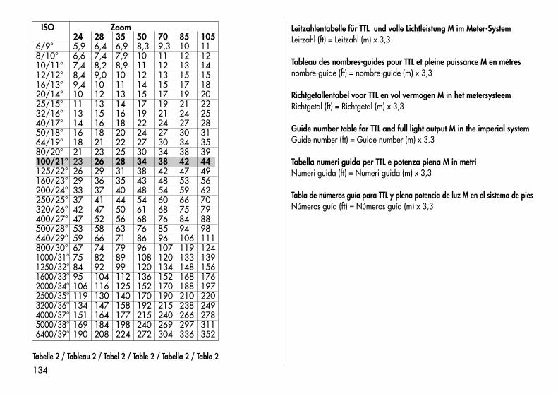
134
ISO Zoom24 28 35 50 70 85 105
6/9° 5,9 6,4 6,9 8,3 9,3 10 118/10° 6,6 7,4 7,9 10 11 12 1210/11° 7,4 8,2 8,9 11 12 13 1412/12° 8,4 9,0 10 12 13 15 1516/13° 9,4 10 11 14 15 17 1820/14° 10 12 13 15 17 19 2025/15° 11 13 14 17 19 21 2232/16° 13 15 16 19 21 24 2540/17° 14 16 18 22 24 27 2850/18° 16 18 20 24 27 30 3164/19° 18 21 22 27 30 34 3580/20° 21 23 25 30 34 38 39100/21° 23 26 28 34 38 42 44125/22° 26 29 31 38 42 47 49160/23° 29 36 35 43 48 53 56200/24° 33 37 40 48 54 59 62250/25° 37 41 44 54 60 66 70320/26° 42 47 50 61 68 75 79400/27° 47 52 56 68 76 84 88500/28° 53 58 63 76 85 94 98640/29° 59 66 71 86 96 106 111800/30° 67 74 79 96 107 119 1241000/31° 75 82 89 108 120 133 1391250/32° 84 92 99 120 134 148 1561600/33° 95 104 112 136 152 168 1762000/34° 106 116 125 152 170 188 1972500/35° 119 130 140 170 190 210 2203200/36° 134 147 158 192 215 238 2494000/37° 151 164 177 215 240 266 2785000/38° 169 184 198 240 269 297 3116400/39° 190 208 224 272 304 336 352
Leitzahlentabelle für TTL und volle Lichtleistung M im Meter-SystemLeitzahl (ft) = Leitzahl (m) x 3,3
Tableau des nombres-guides pour TTL et pleine puissance M en mètresnombre-guide (ft) = nombre-guide (m) x 3,3
Richtgetallentabel voor TTL en vol vermogen M in het metersysteemRichtgetal (ft) = Richtgetal (m) x 3,3
Guide number table for TTL and full light output M in the imperial system Guide number (ft) = Guide number (m) x 3.3
Tabella numeri guida per TTL e potenza piena M in metriNumeri guida (ft) = Numeri guida (m) x 3,3
Tabla de números guía para TTL y plena potencia de luz M en el sistema de piesNúmeros guía (ft) = Números guía (m) x 3,3
Tabelle 2 / Tableau 2 / Tabel 2 / Table 2 / Tabella 2 / Tabla 2
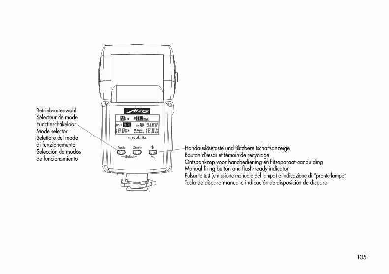
135
44 AF-02
BetriebsartenwahlSélecteur de modeFunctieschakelaarMode selectorSelettore del mododi funzionamentoSelección de modosde funcionamiento
Handauslösetaste und BlitzbereitschaftsanzeigeBouton d’essai et témoin de recyclageOntspanknop voor handbediening en flitsaparaat-aanduidingManual firing button and flash-ready indicatorPulsante test (emissione manuale del lampo) e indicazione di “pronto lampo”Tecla de disparo manual e indicación de disposición de disparo
A M TTLo.k.REAR
LoPDE HSS
PISOEV
M. ZoomAuto Zoom
Exmm
ftm
ML
Mode Zoom
mecablitz
Select
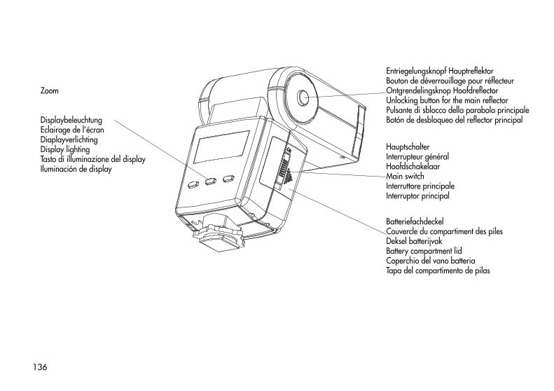
136
44 AF-03
BatteriefachdeckelCouvercle du compartiment des pilesDeksel batterijvakBattery compartment lidCoperchio del vano batteriaTapa del compartimento de pilas
Entriegelungsknopf HauptreflektorBouton de déverrouillage pour réflecteurOntgrendelingsknop HoofdreflectorUnlocking button for the main reflectorPulsante di sblocco della parabola principaleBotón de desbloqueo del reflector principal
HauptschalterInterrupteur généralHoofdschakelaarMain switchInterruttore principaleInterruptor principal
Zoom
DisplaybeleuchtungEclairage de l’écranDiaplayverlichtingDisplay lightingTasto di illuminazione del displayIluminación de display
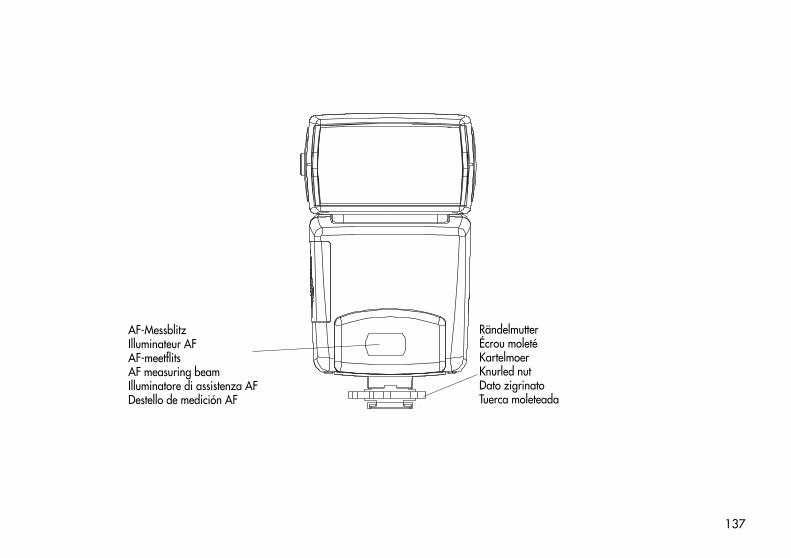
137
44 AF-3C
AF-MessblitzIlluminateur AFAF-meetflitsAF measuring beamIlluminatore di assistenza AFDestello de medición AF
RändelmutterÉcrou moletéKartelmoerKnurled nutDato zigrinatoTuerca moleteada
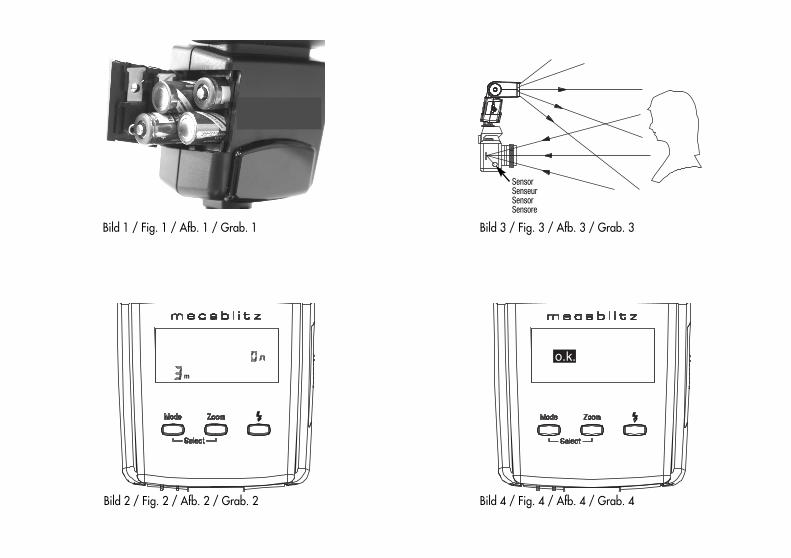
Bild 1 / Fig. 1 / Afb. 1 / Grab. 1
Bild 2 / Fig. 2 / Afb. 2 / Grab. 2
m
Bild 3 / Fig. 3 / Afb. 3 / Grab. 3
SensorSenseurSensorSensore
Bild 4 / Fig. 4 / Afb. 4 / Grab. 4
o.k.

Bild 5 / Fig. 5 / Afb. 5 / Grab. 5
Bild 6 / Fig. 6 / Afb. 6 / Grab. 6
Bild 7 / Fig. 7 / Afb. 7 / Grab. 7
Bild 8 / Fig. 8 / Afb. 8 / Grab. 8

140
✍ ✍
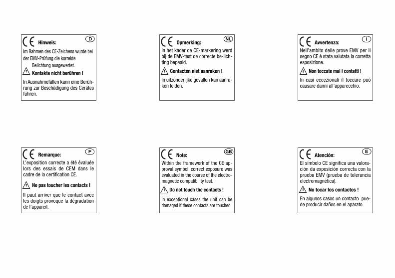
Hinweis:
Im Rahmen des CE-Zeichens wurde beider EMV-Prüfung die korrekte
Belichtung ausgewertet.
Kontakte nicht berühren !
In Ausnahmefällen kann eine Berüh-rung zur Beschädigung des Gerätesführen.
�
Remarque:L’exposition correcte a été évaluéelors des essais de CEM dans lecadre de la certification CE.
Ne pas toucher les contacts !
Il paut arriver que le contact avecles doigts provoque la dégradationde l’appareil.
�
Opmerking:In het kader de CE-markering werdbij de EMV-test de correcte be-lich-ting bepaald.
Contacten niet aanraken !
In uitzonderlijke gevallen kan aanra-ken leiden.
�
Note:Within the framework of the CE ap-proval symbol, correct exposure wasevaluated in the course of the electro-magnetic compatibility test.
Do not touch the contacts !
In exceptional cases the unit can bedamaged if these contacts are touched.
�
Avvertenza:Nell’ambito delle prove EMV per ilsegno CE è stata valutata la correttaesposizione.
Non toccate mai i contatti !
In casi eccezionali il toccare puòcausare danni all’apparecchio.
�
Atención:El símbolo CE significa una valora-ción da exposición correcta con laprueba EMV (prueba de toleranciaelectromagnética).
No tocar los contactos !
En algunos casos un contacto pue-de producir daños en el aparato.
�
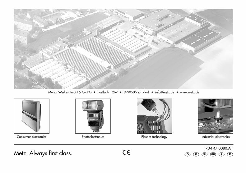
704 47 0080.A1
� � � � � �
Consumer electronics Photoelectronics Plastics technology Industrial electronics
Metz - Werke GmbH & Co KG • Postfach 1267 • D-90506 Zirndorf • [email protected] • www.metz.de
Metz. Always first class.


![4.- Secrets [Melinda Metz]](https://img.pdfslide.us/doc/110x75/5571fc184979599169967b52/4-secrets-melinda-metz.jpg)