Embed Size (px)
Citation preview

MANUAL Servicebox 815/818

Thank you for purchasing this Servicebox to your 815/818!
This guide provides the information needed to service and maintain your spreader at 5,000 hour service. A spreader used and serviced properly retain their qualities for a long and profitable life in service, and you get the full advantage of all the features.
Maintenance may only be carried out by qualified personnel.
For more detailed information about spare parts and service instructions, we refer to our manual for the specific spreader.
All information, illustrations and specifications in this manual are based on the latest information at the time of publication. The right is reserved to make changes at any time without notice. COPYRIGHT© 2015 ELME Spreader AB.

IndexTwistlock Assembly 4-9
Wear pads 10-11
Flextrack Chain Assembly 12-13
Additional Parts 14-17
Summary of all parts included 18
Why use Genuine Parts? 19

The twistlock is a genuine ELME part, which is certified and marked with a unique serial number.
TWISTLOCK ASSEMBLY

8
910
11
The tie-rod is a fixed unit and is not adjustable.
To remove the tie-rod proceed as follows:
1 Remove the Locked / Not locked sensor bracket (item 1).
2 Loosen one of the adjuster bolts at the twistlock cylinder, enough to give some play.
3 Loosen and remove the M8 x 80 bolts (item 2) in the top of both twistlocks in the same end beam.
4 Use two of the M8 x 80 bolts (item 2) as pullers by inserting them in the two threaded holes (item 3) in each of the cranks (item 4) and tighten them alternately until they lift the cranks (item 4) off the top of the twistlock shaft (item 5).
5 The tie-rod (item 6) including both cranks (item 4) can now be removed from the endbeam. Now, it is also possible to replace the O-ring, washer and ball joint (item 14).
To remove the twistlock and sleeve proceed as follows:
6 The key (item 7) that locates the crank (item 4) to the twistlock (item 5) is held in place on the twistlock by a roll pin, so that it will remain in place on the twistlock after the crank is removed. By lightly knocking the key away from the twistlock, it can be removed.
1213
1
23 4 6
7
5
5
14

7 Support the twistlock (item 5) from below so that it does not drop out. Using a screwdriver prise the collets (item 8) out of the recess in the twistlock (item5). It is now possible to lower the twistlock out of the end beam. The sleeve (item 9) and lower bearing set (item 10) will in most cases accompany the twistlock as it is removed. This is quite normal.
Inspection prior to reassembly
8 After removal of all twistlock parts, remove all grease and dirt from the parts and also from the corner of the end beam. Steam clean or clean with some form of solvent.
9 Heck the twistlock (item 5) for wear at the head and also for wear at the bushing surfaces. Inspect the lower (item 10) and upper (item 11) bearing sets for wear and damage. If badly worn or damaged, they should be replaced. The collets (item 8) and and the crank (item 4) should be inspected for possible wear or damage and replaced if necessary.
It should be noted that the state of the collets (item 8) and the recess in the twistlock (item 5) is very important, as these parts are carrying the load when a containerislifted.
Replacing / Fitting twistlocks
10 Prepare the sleeve (item 9), place and grease the bushing and fit the four cente- ring springs in the sides of the sleeve.
11 Grease the upper bearing set (item 11) and place in position on the greased top surface of the corner plate (in the endbeam) with the convex half uppermost (threaded holes up). Grease the lower bearing set (item 10) and place in position on the greased bottom surface of the corner plate (in the endbeam, the grease will hold it in place).
12 Lift the sleeve assembly as assembled in point 10 and position up through the corner plate in the endbeam. Note the direction of the grease nipple! Then place the twistlock in the sleeve, ensuring that both bearings (item 10 and 11) are posi- tioned correctly around the twistlock. Support the assembly with a jack or other means.
13 Fit the collets (item 8) with the pointed part upwards.
14 Fit the key (item 7) incl. roll pin to the keyway of the twistlock (item 5).
6

15 In order to fit the tie-rod (item 6), it is necessary to mount both cranks (item 4) to the tie-rod before placing it in the end beam. Fit the ball joints, O rings, and plastic washers to the tie-rod ends and then fit the fork of the crank (item 4) over the tie- rod end. Ensure that the countersunk ends of the securing holes in the crank are upper most. Secure the crank to the tie-rod end by fitting the pin (item 12) and then the ring pin and allen screw (item 13).
16 In order to simplify assembly of the crank to the twistlock, it is advisable to fit two alignment pins to the assemby. The pins can be made from two M8 x 75 bolts or allen screws with the heads removed and slightly chamfered. These pins should be screwed into the top plate of the upper bearing (item 11) diagonally so that each pin guides one half of the collets (item 8).
17 Insert the tie-rod (item 6) into the end beam and then fit the cranks (item 4) onto the alignment pins and ensure that the key and keyway line up. Fit two of the allens securing (item 2) in the remaining two holes and screw in and tighten lightly. Remove the alignment pins and fit the other two securing screws. The securing screws can now be tightened to approx. 25 Nm.
18 Activate the twistlocks to the NOT LOCKED position and then adjust the twistlock cylinder adjuster bolts, so that the twistlocks are positioned accurately in the NOT LOCKED position. Then adjust properly, see ”Twistlock angle adjustment”.
19 Grease the complete assembly with a high-pressure grease gun.
In order to test the operation, it is necessary to land the spreader on a container so that the seated pins are activated.
7
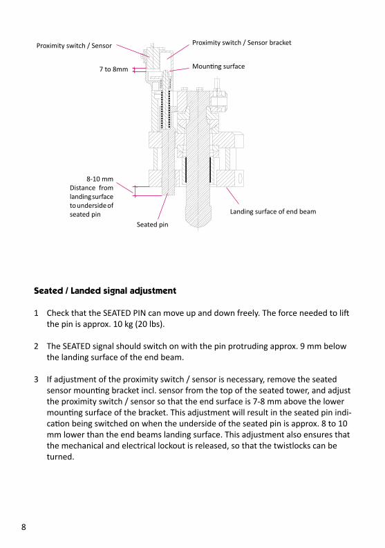
8-10 mm Distance from landing surface to underside of seated pin
Mounting surface
Landing surface of end beam
Seated pin
Proximity switch / Sensor Proximity switch / Sensor bracket
7 to 8mm
Seated / Landed signal adjustment
1 Check that the SEATED PIN can move up and down freely. The force needed to lift the pin is approx. 10 kg (20 lbs).
2 The SEATED signal should switch on with the pin protruding approx. 9 mm below the landing surface of the end beam.
3 If adjustment of the proximity switch / sensor is necessary, remove the seated sensor mounting bracket incl. sensor from the top of the seated tower, and adjust the proximity switch / sensor so that the end surface is 7-8 mm above the lower mounting surface of the bracket. This adjustment will result in the seated pin indi- cation being switched on when the underside of the seated pin is approx. 8 to 10 mm lower than the end beams landing surface. This adjustment also ensures that the mechanical and electrical lockout is released, so that the twistlocks can be turned.
8
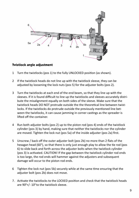
1
2b2a 3 5b5a
4 4
6
Twistlock angle adjustment
1 Turn the twistlocks (pos 1) to the fully UNLOCKED position (as shown).
2 If the twistlock heads do not line up with the twistlock sleeve, they can be adjusted by loosening the lock nuts (pos 5) for the adjuster bolts (pos 2).
3 Turn the twistlocks at each end of the end beam, so that they line up with the sleeves. If it is found difficult to line up the twistlocks and sleeves accurately distri- bute the misalignment equally on both sides of the sleeve. Make sure that the twistlock heads DO NOT protrude outside the the theoretical line between twist- locks. If the twistlocks do protrude outside the previously mentioned line bet- ween the twistlocks, it can cause jamming in corner castings as the spreader is lifted off the container.
4 Run both adjuster bolts (pos 2) up to the piston rod (pos 4) ends of the twistlock cylinder (pos 3) by hand, making sure that neither the twistlocks nor the cylinder are moved. Tighten the lock nut (pos 5a) of the inside adjuster (pos 2a) first.
5 Unscrew / back off the outer adjuster bolt (pos 2b) no more than 2 flats of the hexagan head (60°), so that there is only just enough play to allow the tie rod (pos 6) to slide back and forth across the adjuster bolts when the twistlock cylinder (pos 3) is activated. CAUTION! If the gap between the twistlock cylinder rod ends is too large, the rod ends will hammer against the adjusters and subsequent damage will occur to the piston rod ends.
6 Tighten the lock nut (pos 5b) securely while at the same time ensuring that the adjuster bolt (pos 2b) does not move.
7. Activate the twistlocks to the LOCKED position and check that the twistlock heads are 900+/- 100 to the twistlock sleeve.
9
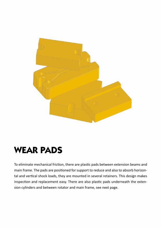
To eliminate mechanical friction, there are plastic pads between extension beams and main frame. The pads are positioned for support to reduce and also to absorb horizon-tal and vertical shock loads, they are mounted in several retainers. This design makes inspection and replacement easy. There are also plastic pads underneath the exten-sion cylinders and between rotator and main frame, see next page.
WEAR PADS

The nylon wear pads should be inspected for wear at the same time as their tracks are lubricated. Replacing the wear pads can be done with ordinary hand tools and without removing the beams.
The pads should be replaced when their thickness is reduced to minimum 18 mm.
Minimum 18 mm
11
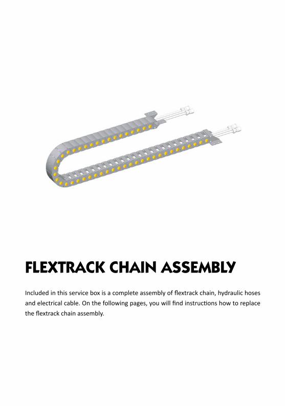
Included in this service box is a complete assembly of flextrack chain, hydraulic hoses and electrical cable. On the following pages, you will find instructions how to replace the flextrack chain assembly.
FLEXTRACK CHAIN ASSEMBLY

Remove the extension cylinder (item 1) and old flextrack chain (item 2) from the end-beam and dismount hoses (item 3) and cable (not shown on the picture below). Replace with new flextrack chain assembly according to below instructions.
Fasten the flextrack chain with bolts (M8x20 + locking nut) onto the flextrack bracket (item 4), which is moulded on the shell.
Strap the flextrack chain provisionally to the valve assembly (item 5). Remove the strap, when the cylinder is mounted in the extension beam.
Pull the cable (not shown on picture above) and the hoses (item 3) through the flextrack chain. Please note! Mark one of the hoses, to avoid mix-up! The male on the cable should come out where the valve assembly is. Place the cylinder (item 1), so that it rests on the flextrack chain.
Turn up and pull the hoses (item 3) towards the valve assembly and fasten them with hose clamps (item 6).
Remount the extension cylinder into the endbeam.
4
3
5
1
23
6
13
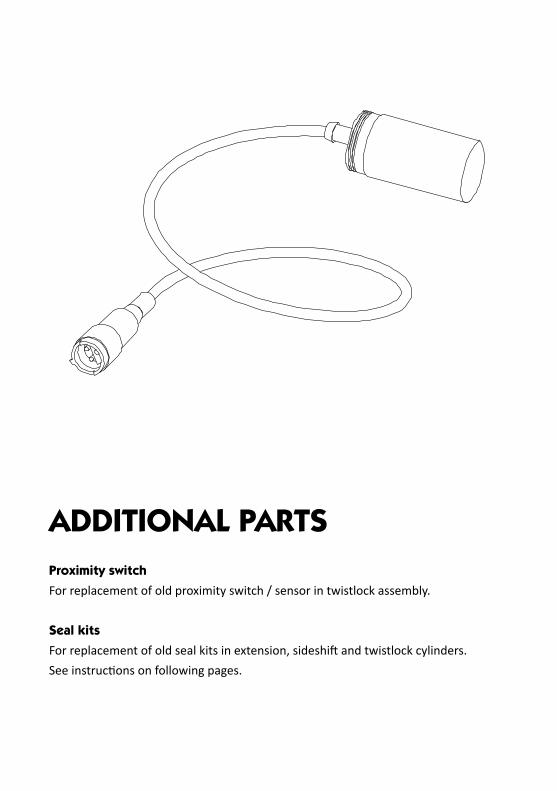
ADDITIONAL PARTSProximity switchFor replacement of old proximity switch / sensor in twistlock assembly.
Seal kitsFor replacement of old seal kits in extension, sideshift and twistlock cylinders.See instructions on following pages.

15
Seal replacement - Slew/reach cylinder
Remove the slew/reach cylinder or tie up the cylinder when working on the spreader.Loosen gland (item 3) and hydraulic hoses and pull out the piston rod (item 1). Be careful not to damage the piston rod when removing and beware of the oil spill.Use a drift punch to remove the roll pin (item 6) and remove the nut (item 5), the piston (item 4) and the gland (item 3) from the piston rod. Check the piston rod and cylinder for damages that can cause leakage and repair or replace when necessary.Carefully remove the seals (items 2), do not damage the surfaces. Clean all parts. Place the new seals with oil or grease. Place the gland and the piston on the piston rod, tighten the nut and secure it with the roll pin. Slide the piston rod assy. into the cylinder and tighten the gland.
1
23
2
42
56

Seal replacement - Extension cylinder
Remove the extension cylinder. Remove the 140 Bar relief valve from the side of the extension cylinder valve. (Wrench 7/8”). Remove the bolts (item 12), and place the ring (item 10) on the painted front side of the piston rod, so that it cannot damage the surface of the rod.Pull out the piston rod, beware of the oil spill (place the hydraulic hose from the front end in a oil bin) and be carefull not to damage the piston rod. Use a drift punch to remove the roll pin (item 2) and remove the nut (item 3), the piston (item 4), the spacer (item 5), the gland (item 7) and the washer (item 9). Check the piston rod and cylinder for damages that can cause leakage and repair or replace when necessary.Carefully remove the seals (items 1). Do not damage the surfaces. Check the bushing (item 6) and the guide ring (item 8) and replace if necessary. Clean all parts.Place the new seals with oil or grease. Place the washer, gland, spacer and piston on the piston rod, tighten the nut and secure it with the roll pin. Slide the piston rod assembly into the cylinder, place the ring (item 10) and tighten the bolts evenly (78 Nm). Place the 140 Bar relief valve and tighten it. (45 Nm).
1 3 4 15 1
6 7 1 8 9 1 10
11
12
16

Seal replacement - Twistlock cylinder
Before disassembly, check the piston rod ends. Repair/grind if they are damaged.Remove the allen screws (item 2 and 12). Remove the washers (item 4) and the plates (item 6) and pull out the piston rod (item 1). Use a drift punch to remove the roll pin from the piston (item 11) and remove the piston from the rod.Carefully remove the seals (items 3, 5, 7, 9 and 10), do not damage the surfaces. Clean all parts. Check the piston rod and cylinder for damages that can cause leakage and repair or replace when necessary. Place the new seals with oil or grease.Slide the piston on the piston rod so that the securing holes line up and place the roll pin. Slide the piston rod in the cylinder, place the plates (item 6) and tighten the M8x160 mm bolts (23 Nm). Place the plates (item 4) and tighten the bolts (23 Nm).
7 5 4
2
3
12
1
2 3 4 5 67 8 9 10 11
17

Summary of all parts included in the box:
Twistlock Assembly 4x Twistlock kit 8x Seal ring 8x O-ring 4x Ball joint 4x Seated pin 4x Nut 4x Indicator arm 4x Compression spring 4x Compression spring 4x Tie rod
Wear pads 20x Wear pad - Mainframe/ Extension beam 4x Wear pad - Mainframe 4x Wear pad - Extension cylinder
Flextrack Chain Assembly 2x Flex track chain 4x Bracket 16x Screw 4x Hydraulic hose assy. 2x Cable assy.
Additional Items 4x Proximity switch 3x Seal kit - Slew/reach cylinder 1x Seal kit - Extension cylinder 1x Seal kit - Twistlock cylinder
18

ELME GENUINE PARTSBy using ELME genuine parts, you always get parts you can rely on and true peace of
mind. If you are using non-genuine parts, you put weak links into a strong, perfectly
designed chain of interactive components. Please note that non-genuine parts are made
by factories that have not been approved by ELME and they are often manufactured to be
as cheap as possible, using inferior materials, workmanship and by reversed engineering.
Non-genuine parts are high risk. Real cost and real risk is measured not in the price, but in
the cost of the component in the event of failure. Use of non-genuine parts may lead to
higher downtime and lower productivity due to more frequent failures. For correct operation
of the spreader, only ELME Genuine Parts and accessories which are approved by ELME should
be used. If non-genuine parts are used, the warranty is not valid. By using ELME Genuine Parts
and accessories approved by ELME, you will maintain original standard. ELME will disclaim all
responsibility if parts from third party are used.
INSPECTION/MAINTENANCEAlways inspect your spreader before using it. If any kind of damage is detected – which may af-
fect the function of the spreader - this must be corrected before use. If the spreader needs to be
repaired, please contact a specialist and see to that only ELME Genuine Parts are used if need of
replacement. This is to ensure that the spreader still is reliable. Repairs made by a non-qualified
person or use of non-genuine parts may lead to increased risk of personal injuries or damages.
Service and maintenance are necessary to keep capacity and efficiency of the spreader for many
years.
MODIFICATION OF THE SPREADER/PRODUCT LIABILITY/WARRANTYFor the avoidance of doubt, ELME is not liable in case of damage due to factors beyond ELME’s
control or due to a lack of maintenance or the use of non-genuine parts. The spreader should
not be modified without consultation with ELME. If so, this means that the spreader is not CE
approved and thus ELME has no product liability.
Why use Genuine Parts?
19

HEADOFFICEELME Spreader AB Älmhult, [email protected]
SALES AND SPARE PARTSELME Spreader Trading (Shanghai) Co. Ltd Shanghai, [email protected]
SPARE PARTSELME Americas Inc. Martin, TN, United [email protected]
© E
LME
Spr
eade
r AB
• 20
15