Embed Size (px)
DESCRIPTION
Manual de usuario en Inglés para los analizadores semiautomáticos Clindiag Sa-10 y Sa-20.
Citation preview
User’s Manual
SA-10/20 Semi-Automatic Clinical Chemistry Analyzer
0
CLINDIAG SYSTEMS USA
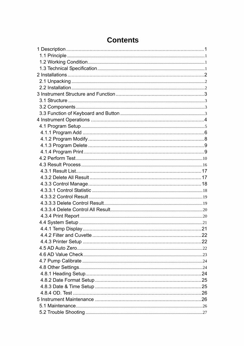
Contents 1 Description ....................................................................................................1 1.1 Principle ...............................................................................................................................1 1.2 Working Condition............................................................................................................1 1.3 Technical Specification ...................................................................................................1
2 Installations ...................................................................................................2 2.1 Unpacking ...........................................................................................................................2 2.2 Installation ...........................................................................................................................2
3 Instrument Structure and Function ................................................................3 3.1 Structure ..............................................................................................................................3 3.2 Components .......................................................................................................................3 3.3 Function of Keyboard and Button ..............................................................................3
4 Instrument Operations ..................................................................................4 4.1 Program Setup ..................................................................................................................5 4.1.1 Program Add ........................................................................................6 4.1.2 Program Modify ....................................................................................8 4.1.3 Program Delete ....................................................................................9 4.1.4 Program Print .......................................................................................9 4.2 Perform Test .....................................................................................................................10 4.3 Result Process ................................................................................................................16 4.3.1 Result List...........................................................................................17 4.3.2 Delete All Result .................................................................................17 4.3.3 Control Manage..................................................................................18 4.3.3.1 Control Statistic ......................................................................................................18 4.3.3.2 Control Result .........................................................................................................19 4.3.3.3 Delete Control Result...........................................................................................19 4.3.3.4 Delete Control All Result.....................................................................................204.3.4 Print Report .................................................................................................................20
4.4 System Setup ..................................................................................................................21 4.4.1 Temp Display......................................................................................21 4.4.2 Filter and Cuvette ...............................................................................22 4.4.3 Printer Setup ......................................................................................22 4.5 AD Auto Zero....................................................................................................................22 4.6 AD Value Check ..............................................................................................................23 4.7 Pump Calibrate ...............................................................................................................24 4.8 Other Settings..................................................................................................................24 4.8.1 Heading Setup....................................................................................24 4.8.2 Date Format Setup .............................................................................25 4.8.3 Date & Time Setup .............................................................................25 4.8.4 OD. Test .............................................................................................26
5 Instrument Maintenance .............................................................................26 5.1 Maintenance.....................................................................................................................26 5.2 Trouble Shooting ............................................................................................................27

5.3 Fittings Replacement ....................................................................................................28 5.3.1 Power Supply Fuse ............................................................................28 5.3.2 Peristalsis Pump Tube Replacement..................................................28 5.3.3 Printing Paper Replacement...............................................................28
6 Storage .......................................................................................................28
1 Description SA series of Semi-Automatic Clinical Chemistry Analyzers is used to
measure biochemistry items and a part of immunity items, with characteristics
of high precision, good repetition and complete function.
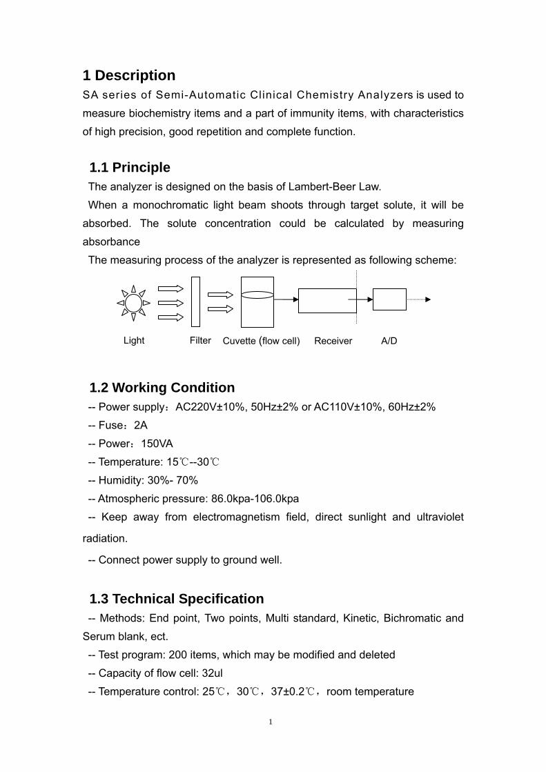
1.1 Principle The analyzer is designed on the basis of Lambert-Beer Law.
When a monochromatic light beam shoots through target solute, it will be
absorbed. The solute concentration could be calculated by measuring
absorbance The measuring process of the analyzer is represented as following scheme:
Light Filter Cuvette (flow cell) Receiver A/D
1.2 Working Condition -- Power supply:AC220V±10%, 50Hz±2% or AC110V±10%, 60Hz±2%
-- Fuse:2A
-- Power:150VA
-- Temperature: 15℃--30℃
-- Humidity: 30%- 70%
-- Atmospheric pressure: 86.0kpa-106.0kpa -- Keep away from electromagnetism field, direct sunlight and ultraviolet
radiation.
-- Connect power supply to ground well.
1.3 Technical Specification -- Methods: End point, Two points, Multi standard, Kinetic, Bichromatic and
Serum blank, ect.
-- Test program: 200 items, which may be modified and deleted -- Capacity of flow cell: 32ul
-- Temperature control: 25℃,30℃,37±0.2℃,room temperature
1
-- Optical system: interferential filters, 340 / 405 / 492 / 510 / 546 / 578 /
620nm and two more filters available.
-- Light source: 6V 10W halogen lamp
-- Photometric range: 0-2.5A
-- Display: LCD screen
-- Printer: built-in thermal printer
-- Serial output: RS-232 standard
-- Dimension: 39cm×37cm×18cm
2 Installations Attention: The instrument should be installed by professionals. 2.1 Unpacking Unpack outer package, and check:
-- If the outer package is broken during transportation,
-- If the packing contents are complete referring to packing list
If you find any problems, please contact the local distributor or Clindiag
service department.
2.2 Installation -- Install the instrument on a stable desk.
-- Connect power cable with the appointed power supply, before connecting
check the voltage of the electricity.
-- Put waste pipe end (at the back of the instrument) into waste bottle. -- If voltage drifts more than 10 %, please connect a stabilizer.
-- Switch on the main machine, before test. The analyzer must be warmed up
for 5 minutes at least.
2
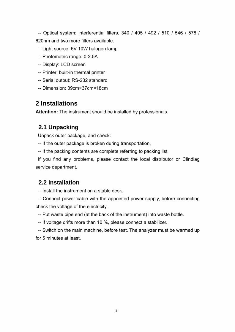
3 Instrument Structure and Function 3.1 Structure
Print cover
Front view
Back view 3.2 Components The main components: SCM, LCD screen, keyboard, aspirating probe, optical
system, peristaltic pump and built-in printer. Flow cell is made of quartz. The volume is 32ul. The advisable aspiration
volume is 300-500ul.
3.3 Function of Keyboard and Button “PUSH” button: used for controlling aspirating sample.
Keyboard: composed of 19 film keys, the key function is listed in Table 1.
Film board
Incubator
“PUSH” button
Fuse Socket
Waste tube connector
3
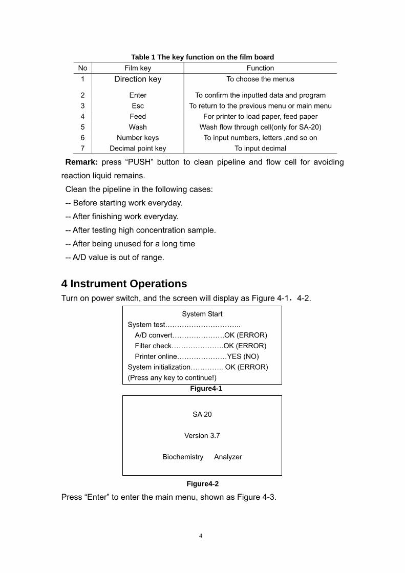
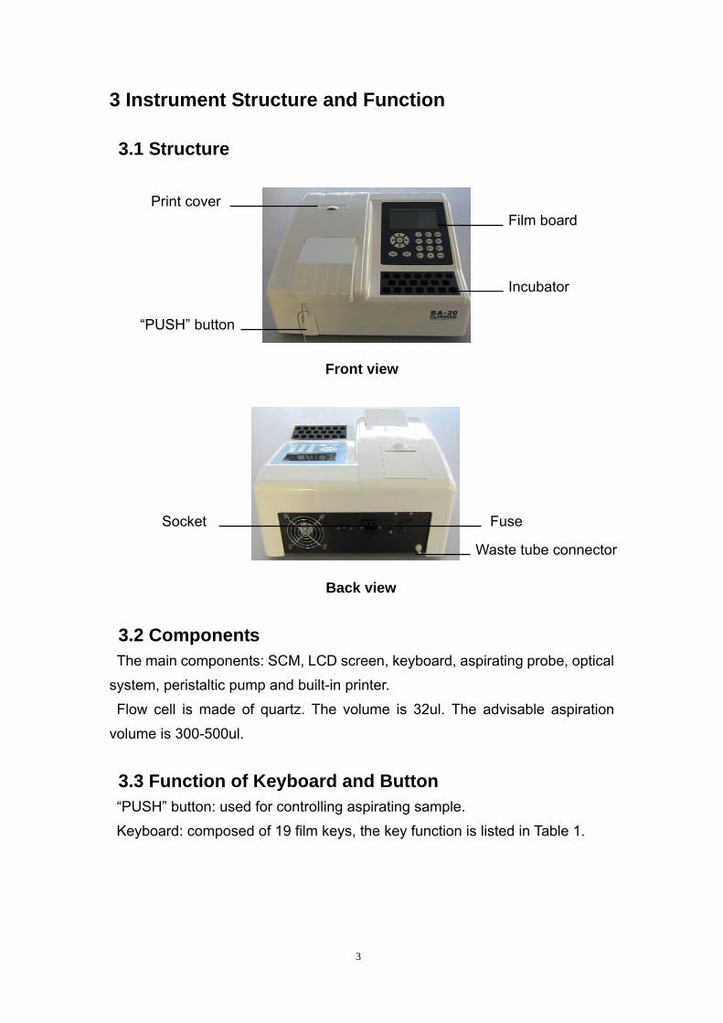
Table 1 The key function on the film board No Film key Function 1 Direction key To choose the menus
2 Enter To confirm the inputted data and program 3 Esc To return to the previous menu or main menu 4 Feed For printer to load paper, feed paper 5 Wash Wash flow through cell(only for SA-20) 6 Number keys To input numbers, letters ,and so on 7 Decimal point key To input decimal
Remark: press “PUSH” button to clean pipeline and flow cell for avoiding
reaction liquid remains.
Clean the pipeline in the following cases:
-- Before starting work everyday.
-- After finishing work everyday.
-- After testing high concentration sample.
-- After being unused for a long time
-- A/D value is out of range.
4 Instrument Operations Turn on power switch, and the screen will display as Figure 4-1,4-2.
Figure4-1
SA 20
Version 3.7
Biochemistry Analyzer
System Start
(Press any key to continue!)
System test………………………….. A/D convert………………….OK (ERROR) Filter check………………….OK (ERROR) Printer online…………………YES (NO)
System initialization………….. OK (ERROR)
Figure4-2
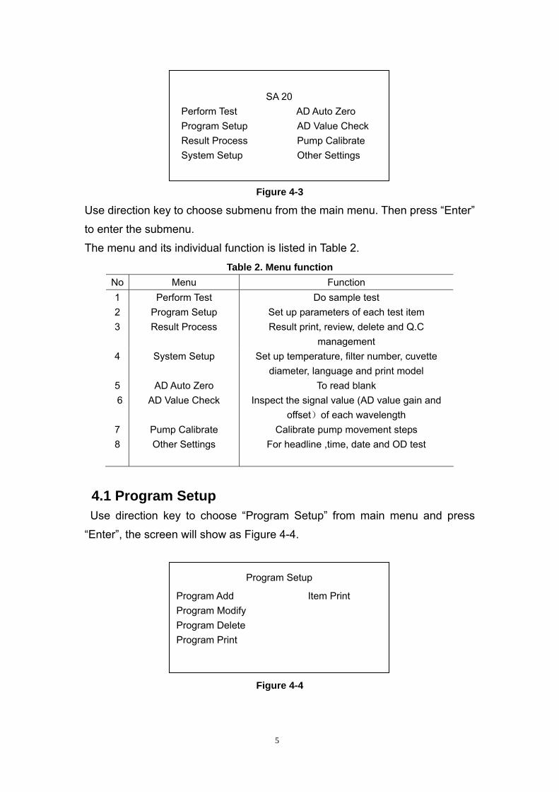
Press “Enter” to enter the main menu, shown as Figure 4-3.
4
Result Process Pump Calibrate System Setup Other Settings
Program Setup AD Value Check Perform Test AD Auto Zero
SA 20
Figure 4-3
Use direction key to choose submenu from the main menu. Then press “Enter”
to enter the submenu.
The menu and its individual function is listed in Table 2.
Table 2. Menu function No Menu Function 1 Perform Test Do sample test 2 Program Setup Set up parameters of each test item 3 Result Process Result print, review, delete and Q.C
management 4 System Setup Set up temperature, filter number, cuvette
diameter, language and print model 5 AD Auto Zero To read blank 6 AD Value Check Inspect the signal value (AD value gain and
offset)of each wavelength 7 Pump Calibrate Calibrate pump movement steps 8 Other Settings For headline ,time, date and OD test
4.1 Program Setup Use direction key to choose “Program Setup” from main menu and press
“Enter”, the screen will show as Figure 4-4.
Program Setup
Program Add Item Print Program Modify Program Delete Program Print
Figure 4-4
5
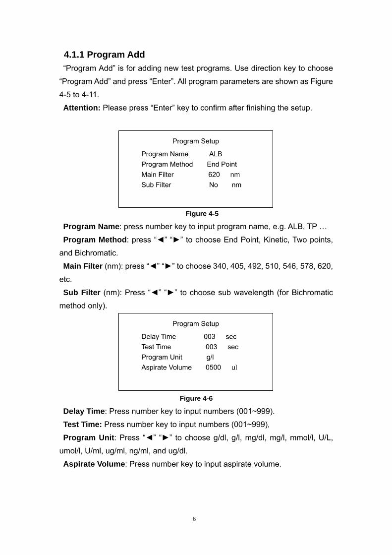
4.1.1 Program Add “Program Add” is for adding new test programs. Use direction key to choose
“Program Add” and press “Enter”. All program parameters are shown as Figure
4-5 to 4-11.
Attention: Please press “Enter” key to confirm after finishing the setup.
Program Name ALB Program Method End Point Main Filter 620 nm Sub Filter No nm
Program Setup
Figure 4-5
Program Name: press number key to input program name, e.g. ALB, TP …
Program Method: press “◄” “►” to choose End Point, Kinetic, Two points,
and Bichromatic.
Main Filter (nm): press “◄” “►” to choose 340, 405, 492, 510, 546, 578, 620,
etc.
Sub Filter (nm): Press “◄” “►” to choose sub wavelength (for Bichromatic
method only).
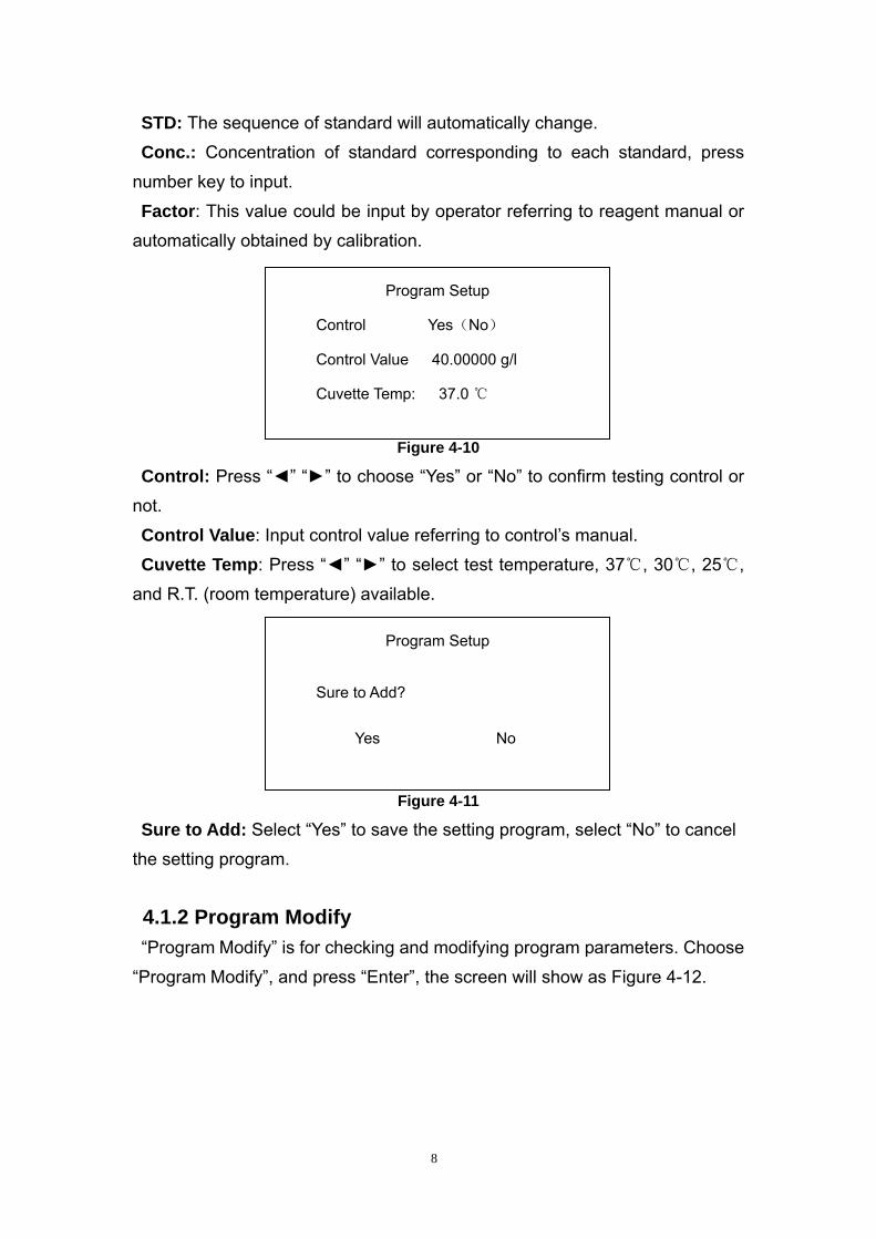
Aspirate Volume 0500 ul
Program Setup
Delay Time 003 sec Test Time 003 sec Program Unit g/l
Figure 4-6
Delay Time: Press number key to input numbers (001~999).
Test Time: Press number key to input numbers (001~999),
Program Unit: Press “◄” “►” to choose g/dl, g/l, mg/dl, mg/l, mmol/l, U/L,
umol/l, U/ml, ug/ml, ng/ml, and ug/dl.
Aspirate Volume: Press number key to input aspirate volume.
6
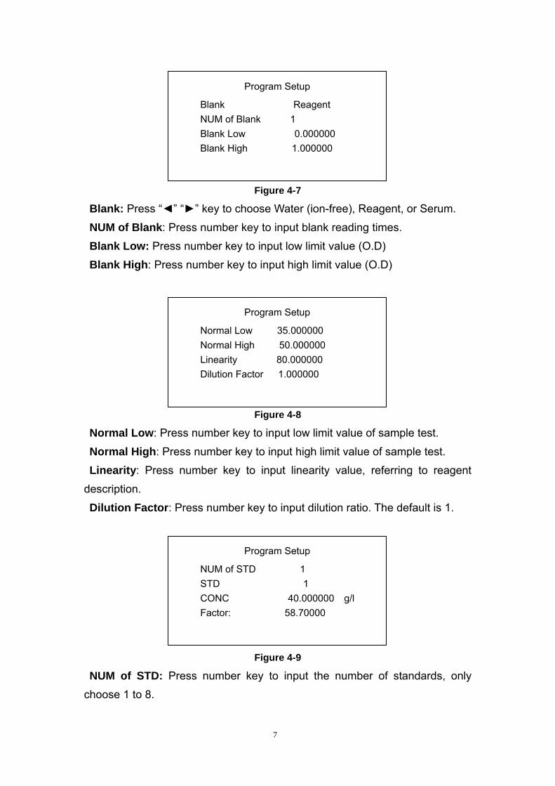
Figure 4-7
Blank: Press “◄” “►” key to choose Water (ion-free), Reagent, or Serum.
NUM of Blank: Press number key to input blank reading times.
Blank Low: Press number key to input low limit value (O.D)
Blank High: Press number key to input high limit value (O.D)
Figure 4-8
Normal Low: Press number key to input low limit value of sample test.
Normal High: Press number key to input high limit value of sample test.
Linearity: Press number key to input linearity value, referring to reagent
description.
Dilution Factor: Press number key to input dilution ratio. The default is 1.
NUM of Blank 1 Blank Low 0.000000 Blank High 1.000000
Program Setup
Normal Low 35.000000 Normal High 50.000000 Linearity 80.000000 Dilution Factor 1.000000
Program Setup
NUM of STD 1 STD 1 CONC 40.000000 g/l Factor: 58.70000
Program Setup
Blank Reagent
Figure 4-9
NUM of STD: Press number key to input the number of standards, only
choose 1 to 8.
7
STD: The sequence of standard will automatically change.
Conc.: Concentration of standard corresponding to each standard, press
number key to input.
Factor: This value could be input by operator referring to reagent manual or
automatically obtained by calibration.
Figure 4-10
Control Yes(No)
Control Value 40.00000 g/l
Cuvette Temp: 37.0 ℃
Program Setup
Control: Press “◄” “►” to choose “Yes” or “No” to confirm testing control or
not.
Control Value: Input control value referring to control’s manual.
Cuvette Temp: Press “◄” “►” to select test temperature, 37℃, 30℃, 25℃,
and R.T. (room temperature) available.
Figure 4-11
Sure to Add?
Yes No
Program Setup
Sure to Add: Select “Yes” to save the setting program, select “No” to cancel
the setting program.
4.1.2 Program Modify
“Program Modify” is for checking and modifying program parameters. Choose
“Program Modify”, and press “Enter”, the screen will show as Figure 4-12.
8
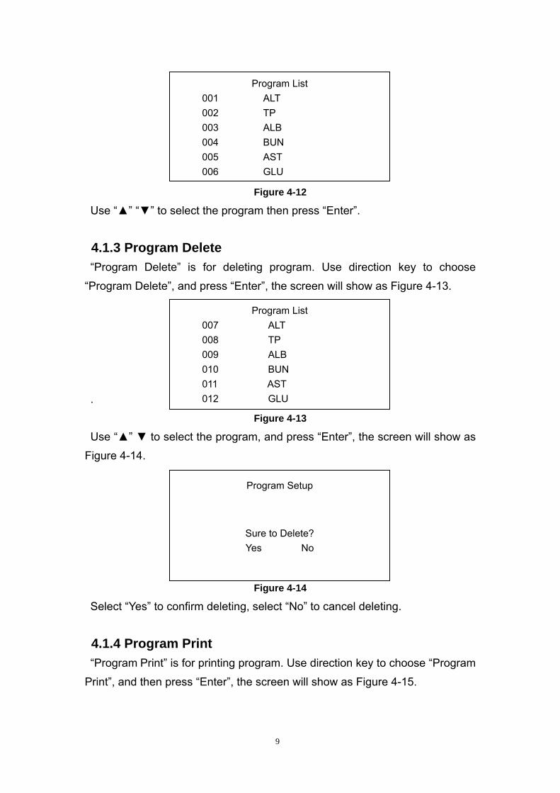
002 TP 003 ALB 004 BUN 005 AST 006 GLU
Program List 001 ALT
Figure 4-12
Use “▲” “▼” to select the program then press “Enter”.
4.1.3 Program Delete
“Program Delete” is for deleting program. Use direction key to choose
“Program Delete”, and press “Enter”, the screen will show as Figure 4-13.
011 AST 012 GLU
Program List 007 ALT 008 TP 009 ALB 010 BUN
.
Figure 4-13
Use “▲” ▼ to select the program, and press “Enter”, the screen will show as
Figure 4-14.
Figure 4-14
Program Setup
Sure to Delete? Yes No
Select “Yes” to confirm deleting, select “No” to cancel deleting.
4.1.4 Program Print
“Program Print” is for printing program. Use direction key to choose “Program
Print”, and then press “Enter”, the screen will show as Figure 4-15.
9
017 AST 018 GLU
Program List 013 ALT 014 TP 015 ALB 016 BUN
Figure 4-15
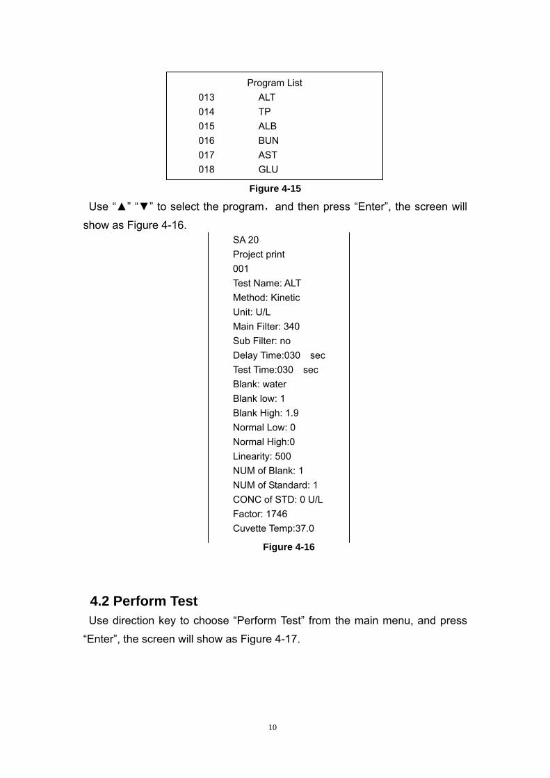
Use “▲” “▼” to select the program,and then press “Enter”, the screen will
show as Figure 4-16. SA 20 Project print 001 Test Name: ALT Method: Kinetic Unit: U/L Main Filter: 340 Sub Filter: no Delay Time:030 sec Test Time:030 sec Blank: water Blank low: 1 Blank High: 1.9 Normal Low: 0 Normal High:0 Linearity: 500 NUM of Blank: 1 NUM of Standard: 1 CONC of STD: 0 U/L Factor: 1746 Cuvette Temp:37.0
Figure 4-16
4.2 Perform Test
Use direction key to choose “Perform Test” from the main menu, and press
“Enter”, the screen will show as Figure 4-17.
10
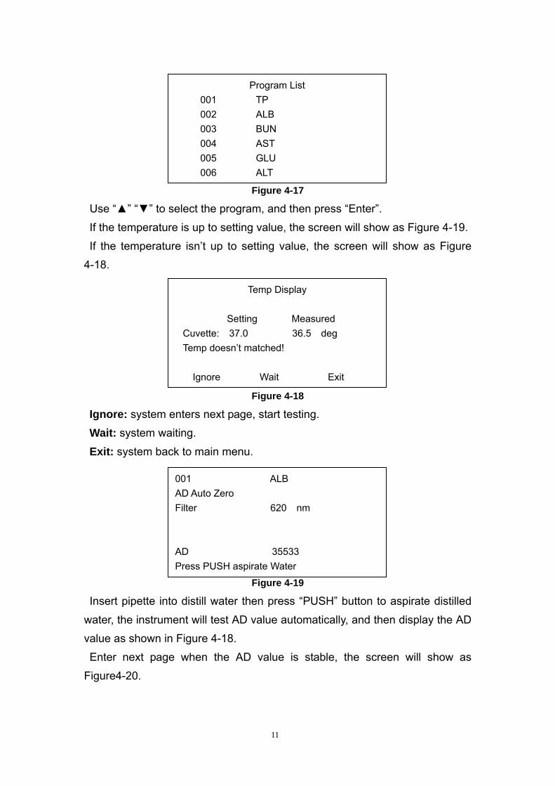
Figure 4-17
005 GLU 006 ALT
Program List 001 TP 002 ALB 003 BUN 004 AST
Use “▲” “▼” to select the program, and then press “Enter”.
If the temperature is up to setting value, the screen will show as Figure 4-19.
If the temperature isn’t up to setting value, the screen will show as Figure
4-18.
Figure 4-18
Ignore: system enters next page, start testing.
Wait: system waiting.
Exit: system back to main menu.
Figure 4-19
001 ALB AD Auto Zero Filter 620 nm AD 35533 Press PUSH aspirate Water
Temp Display
Ignore Wait Exit
Setting Measured Cuvette: 37.0 36.5 deg Temp doesn’t matched!
Insert pipette into distill water then press “PUSH” button to aspirate distilled
water, the instrument will test AD value automatically, and then display the AD
value as shown in Figure 4-18.
Enter next page when the AD value is stable, the screen will show as
Figure4-20.
11

Figure 4-20
If choose “No”, the instrument will use the last blank value and do the
standard test directly. The screen will show as Figure 4-23.
If choose “Yes”, the instrument will do blank test, the screen will show as
Figure 4-21.
Figure 4-21
Insert pipette into blank then press “PUSH” button to aspirate blank. The
instrument will test blank absorbency, then display as shown in Figure 4-22.
Figure 4-22
No Yes
001 ALB Test Blank Press PUSH aspirate Blank
001 ALB Test Blank OD 0.2100 Press Enter to continue
001 ALB Test Blank OD: 0.2100
Press “Enter”, enter the next page, the screen will show as Figure4-23.
12
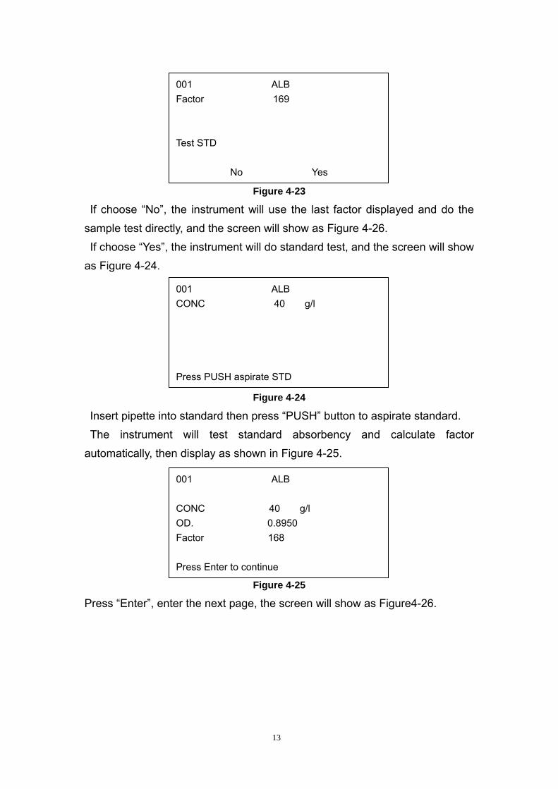
Figure 4-23
If choose “No”, the instrument will use the last factor displayed and do the
sample test directly, and the screen will show as Figure 4-26.
If choose “Yes”, the instrument will do standard test, and the screen will show
as Figure 4-24.
Figure 4-24
Insert pipette into standard then press “PUSH” button to aspirate standard.
The instrument will test standard absorbency and calculate factor
automatically, then display as shown in Figure 4-25.
Figure 4-25
No Yes
001 ALB CONC 40 g/l Press PUSH aspirate STD
001 ALB CONC 40 g/l OD. 0.8950 Factor 168 Press Enter to continue
001 ALB Factor 169 Test STD
Press “Enter”, enter the next page, the screen will show as Figure4-26.
13
No Yes
001 ALB Test Control
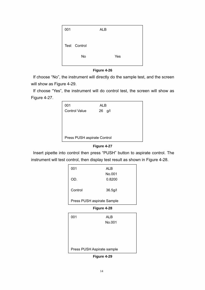
Figure 4-26
If choose “No”, the instrument will directly do the sample test, and the screen
will show as Figure 4-29.
If choose “Yes”, the instrument will do control test, the screen will show as
Figure 4-27.
Figure 4-27
Insert pipette into control then press “PUSH” button to aspirate control. The
instrument will test control, then display test result as shown in Figure 4-28.
Press PUSH aspirate Control
001 ALB No.001
OD. 0.8200 Control 36.5g/l
Press PUSH aspirate Sample
001 ALB Control Value 26 g/l
Figure 4-28
Figure 4-29
Press PUSH Aspirate sample
001 ALB No.001
14
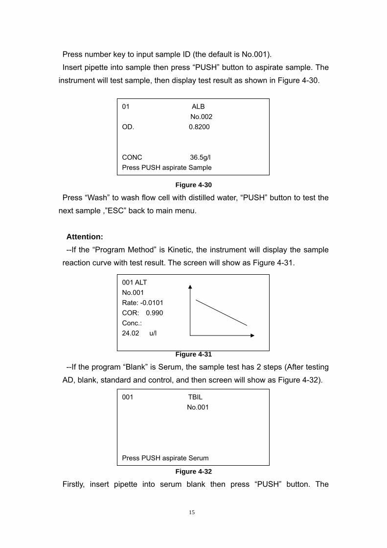
Press number key to input sample ID (the default is No.001).
Insert pipette into sample then press “PUSH” button to aspirate sample. The
instrument will test sample, then display test result as shown in Figure 4-30.
Press PUSH aspirate Sample
01 ALB No.002 OD. 0.8200 CONC 36.5g/l
Figure 4-30
Press “Wash” to wash flow cell with distilled water, “PUSH” button to test the
next sample ,”ESC” back to main menu.
Attention: --If the “Program Method” is Kinetic, the instrument will display the sample
reaction curve with test result. The screen will show as Figure 4-31.
Figure 4-31
001 ALT No.001 Rate: -0.0101 COR: 0.990 Conc.: 24.02 u/l
--If the program “Blank” is Serum, the sample test has 2 steps (After testing
AD, blank, standard and control, and then screen will show as Figure 4-32).
Press PUSH aspirate Serum
001 TBIL No.001
Figure 4-32
Firstly, insert pipette into serum blank then press “PUSH” button. The
15
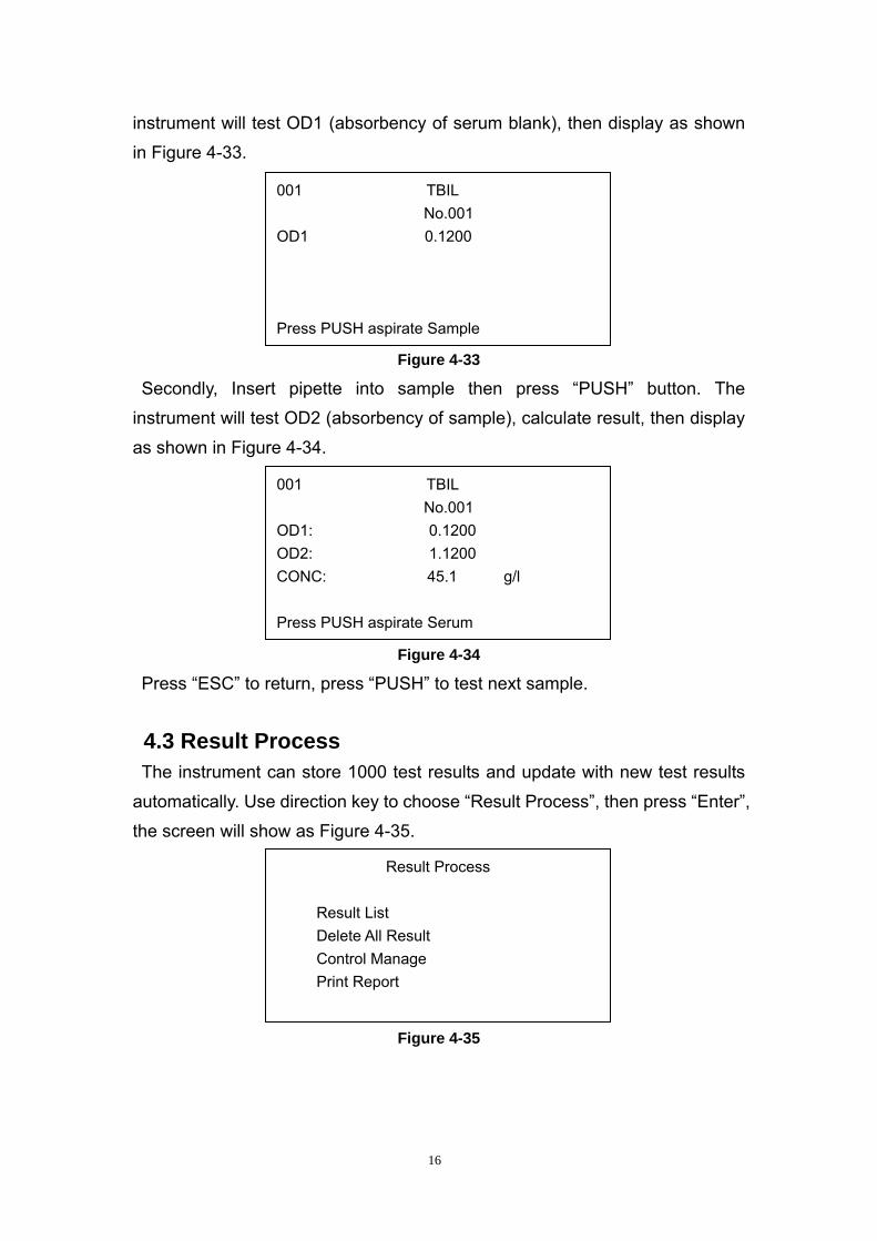
instrument will test OD1 (absorbency of serum blank), then display as shown
in Figure 4-33.
Figure 4-33
Secondly, Insert pipette into sample then press “PUSH” button. The
instrument will test OD2 (absorbency of sample), calculate result, then display
as shown in Figure 4-34.
Press PUSH aspirate Sample
001 TBIL No.001 OD1: 0.1200 OD2: 1.1200
Press PUSH aspirate Serum CONC: 45.1 g/l
001 TBIL No.001 OD1 0.1200
Figure 4-34
Press “ESC” to return, press “PUSH” to test next sample.
4.3 Result Process
The instrument can store 1000 test results and update with new test results
automatically. Use direction key to choose “Result Process”, then press “Enter”,
the screen will show as Figure 4-35.
Print Report
Result Process
Result List Delete All Result Control Manage
Figure 4-35
16
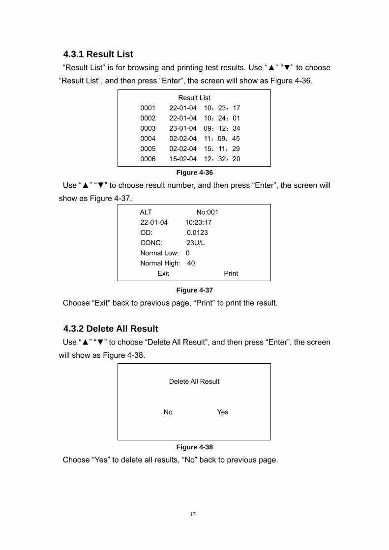
4.3.1 Result List “Result List” is for browsing and printing test results. Use “▲” “▼” to choose
“Result List”, and then press “Enter”, the screen will show as Figure 4-36.
Figure 4-36
Use “▲” “▼” to choose result number, and then press “Enter”, the screen will
show as Figure 4-37.
0005 02-02-04 15:11:29 0006 15-02-04 12:32:20
ALT No:001 22-01-04 10:23:17 OD: 0.0123 CONC: 23U/L Normal Low: 0 Normal High: 40 Exit Print
Result List 0001 22-01-04 10:23:17 0002 22-01-04 10:24:01 0003 23-01-04 09:12:34 0004 02-02-04 11:09:45
Figure 4-37
Choose “Exit” back to previous page, “Print” to print the result.
4.3.2 Delete All Result Use “▲” “▼” to choose “Delete All Result”, and then press “Enter”, the screen
will show as Figure 4-38.
Delete All Result
No Yes
Figure 4-38
Choose “Yes” to delete all results, “No” back to previous page.
17
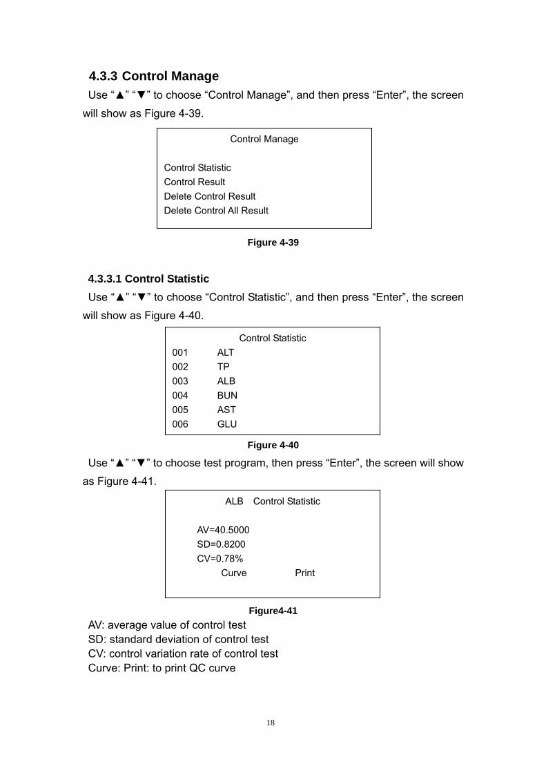
4.3.3 Control Manage Use “▲” “▼” to choose “Control Manage”, and then press “Enter”, the screen
will show as Figure 4-39.
Control Manage
Control Statistic Control Result Delete Control Result Delete Control All Result
Figure 4-39
4.3.3.1 Control Statistic Use “▲” “▼” to choose “Control Statistic”, and then press “Enter”, the screen
will show as Figure 4-40.
Figure 4-40 Use “▲” “▼” to choose test program, then press “Enter”, the screen will show
as Figure 4-41.
006 GLU
ALB Control Statistic
AV=40.5000 SD=0.8200 CV=0.78% Curve Print
Control Statistic 001 ALT 002 TP 003 ALB 004 BUN 005 AST
Figure4-41 AV: average value of control test SD: standard deviation of control test CV: control variation rate of control test Curve: Print: to print QC curve
18
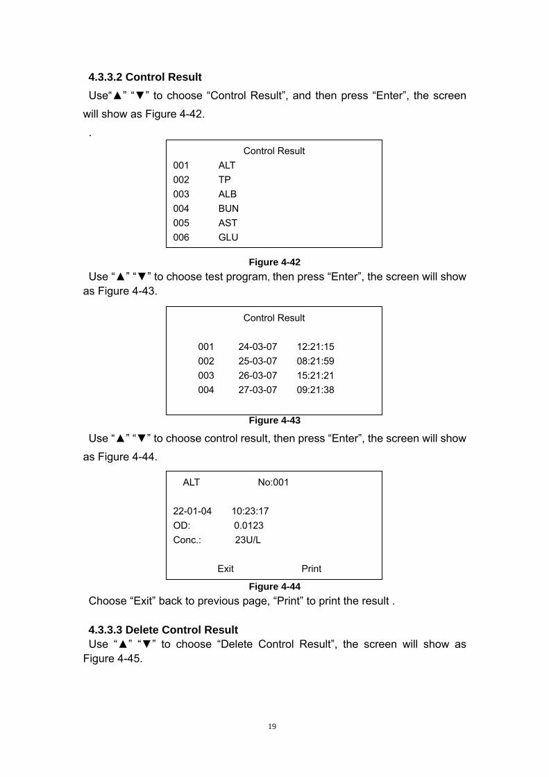
4.3.3.2 Control Result Use“▲” “▼” to choose “Control Result”, and then press “Enter”, the screen
will show as Figure 4-42.
.
Figure 4-42 Use “▲” “▼” to choose test program, then press “Enter”, the screen will show
as Figure 4-43.
Figure 4-43
Use “▲” “▼” to choose control result, then press “Enter”, the screen will show
as Figure 4-44.
Figure 4-44
006 GLU
Control Result
001 24-03-07 12:21:15 002 25-03-07 08:21:59 003 26-03-07 15:21:21 004 27-03-07 09:21:38
ALT No:001 22-01-04 10:23:17 OD: 0.0123 Conc.: 23U/L
Exit Print
Control Result 001 ALT 002 TP 003 ALB 004 BUN 005 AST
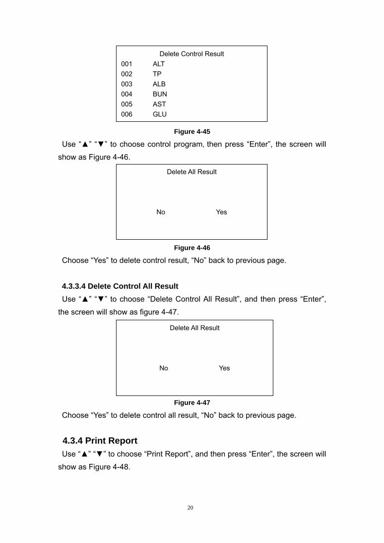
Choose “Exit” back to previous page, “Print” to print the result . 4.3.3.3 Delete Control Result Use “▲” “▼” to choose “Delete Control Result”, the screen will show as
Figure 4-45.
19
005 AST 006 GLU
Delete Control Result 001 ALT 002 TP 003 ALB 004 BUN
Figure 4-45
Use “▲” “▼” to choose control program, then press “Enter”, the screen will
show as Figure 4-46.
Figure 4-46
Choose “Yes” to delete control result, “No” back to previous page.
4.3.3.4 Delete Control All Result Use “▲” “▼” to choose “Delete Control All Result”, and then press “Enter”,
the screen will show as figure 4-47.
No Yes
Delete All Result
No Yes
Delete All Result
Figure 4-47
Choose “Yes” to delete control all result, “No” back to previous page.
4.3.4 Print Report Use “▲” “▼” to choose “Print Report”, and then press “Enter”, the screen will
show as Figure 4-48.
20
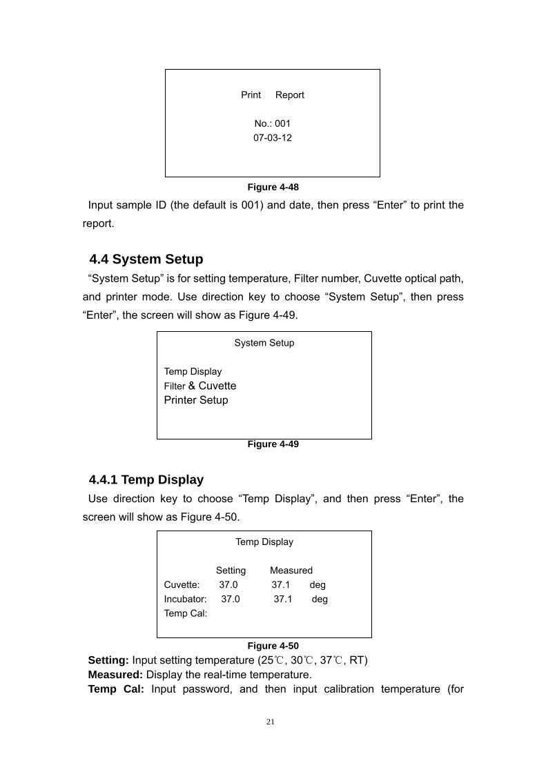
Print Report
No.: 001 07-03-12
Figure 4-48
Input sample ID (the default is 001) and date, then press “Enter” to print the
report.
4.4 System Setup “System Setup” is for setting temperature, Filter number, Cuvette optical path,
and printer mode. Use direction key to choose “System Setup”, then press
“Enter”, the screen will show as Figure 4-49.
Figure 4-49
System Setup
Temp Display Filter & Cuvette Printer Setup
4.4.1 Temp Display Use direction key to choose “Temp Display”, and then press “Enter”, the
screen will show as Figure 4-50.
Figure 4-50
Temp Display
Setting Measured Cuvette: 37.0 37.1 deg Incubator: 37.0 37.1 deg Temp Cal:
Setting: Input setting temperature (25℃, 30℃, 37℃, RT) Measured: Display the real-time temperature. Temp Cal: Input password, and then input calibration temperature (for
21
professionals only).
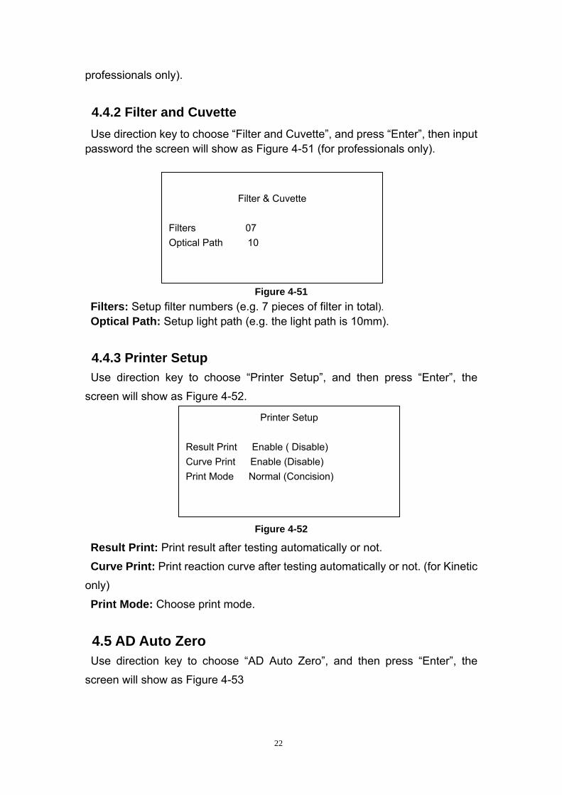
4.4.2 Filter and Cuvette Use direction key to choose “Filter and Cuvette”, and press “Enter”, then input
password the screen will show as Figure 4-51 (for professionals only).
Figure 4-51 Filters: Setup filter numbers (e.g. 7 pieces of filter in total). Optical Path: Setup light path (e.g. the light path is 10mm).
4.4.3 Printer Setup Use direction key to choose “Printer Setup”, and then press “Enter”, the
screen will show as Figure 4-52.
Filter & Cuvette
Filters 07 Optical Path 10
Printer Setup Result Print Enable ( Disable) Curve Print Enable (Disable) Print Mode Normal (Concision)
Figure 4-52
Result Print: Print result after testing automatically or not.
Curve Print: Print reaction curve after testing automatically or not. (for Kinetic
only)
Print Mode: Choose print mode. 4.5 AD Auto Zero Use direction key to choose “AD Auto Zero”, and then press “Enter”, the
screen will show as Figure 4-53
22
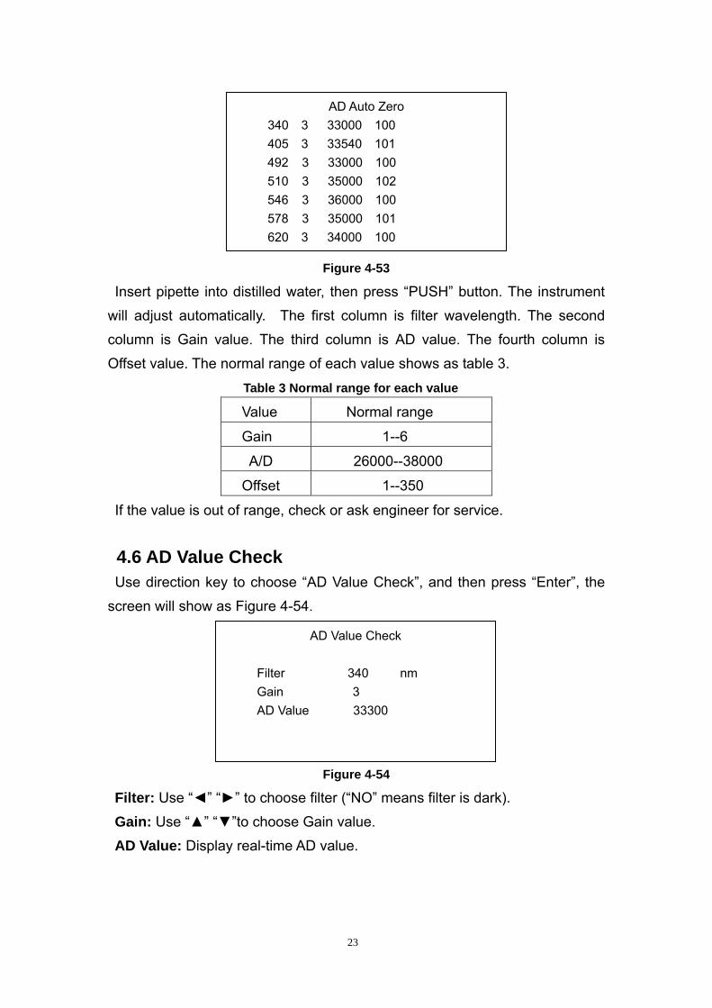
Figure 4-53
Insert pipette into distilled water, then press “PUSH” button. The instrument
will adjust automatically. The first column is filter wavelength. The second
column is Gain value. The third column is AD value. The fourth column is
Offset value. The normal range of each value shows as table 3.
Table 3 Normal range for each value
Value Normal range
Gain 1--6
A/D 26000--38000
Offset 1--350
If the value is out of range, check or ask engineer for service.
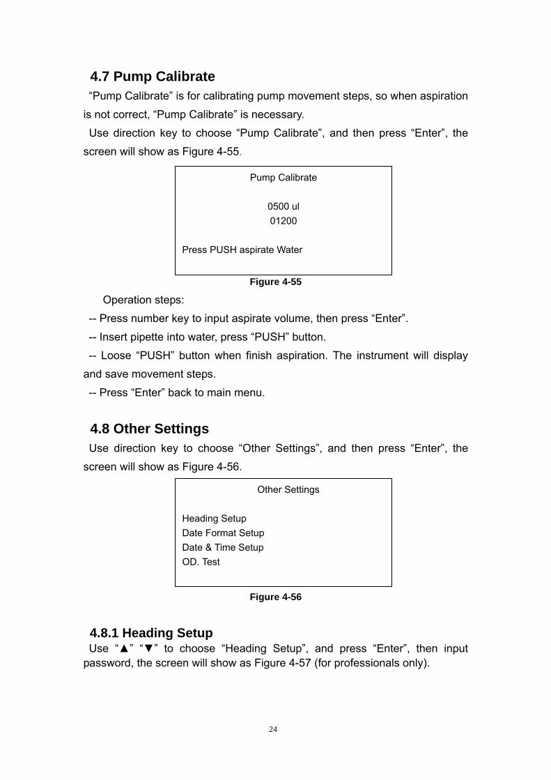
4.6 AD Value Check Use direction key to choose “AD Value Check”, and then press “Enter”, the
screen will show as Figure 4-54.
546 3 36000 100 578 3 35000 101 620 3 34000 100
AD Value Check
Filter 340 nm Gain 3 AD Value 33300
AD Auto Zero 340 3 33000 100 405 3 33540 101 492 3 33000 100 510 3 35000 102
Figure 4-54
Filter: Use “◄” “►” to choose filter (“NO” means filter is dark).
Gain: Use “▲” “▼”to choose Gain value.
AD Value: Display real-time AD value.
23
4.7 Pump Calibrate “Pump Calibrate” is for calibrating pump movement steps, so when aspiration
is not correct, “Pump Calibrate” is necessary.
Use direction key to choose “Pump Calibrate”, and then press “Enter”, the
screen will show as Figure 4-55.
Figure 4-55
01200 Press PUSH aspirate Water
Pump Calibrate
0500 ul
Operation steps:
-- Press number key to input aspirate volume, then press “Enter”.
-- Insert pipette into water, press “PUSH” button.
-- Loose “PUSH” button when finish aspiration. The instrument will display
and save movement steps.
-- Press “Enter” back to main menu.
4.8 Other Settings Use direction key to choose “Other Settings”, and then press “Enter”, the
screen will show as Figure 4-56.
Figure 4-56
Heading Setup Date Format Setup Date & Time Setup OD. Test
Other Settings
4.8.1 Heading Setup Use “▲” “▼” to choose “Heading Setup”, and press “Enter”, then input
password, the screen will show as Figure 4-57 (for professionals only).
24
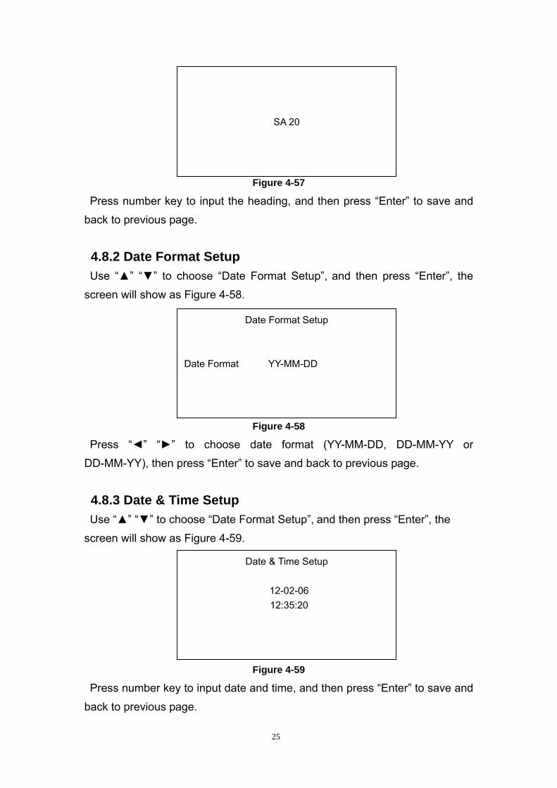
Figure 4-57
Press number key to input the heading, and then press “Enter” to save and
back to previous page.
4.8.2 Date Format Setup Use “▲” “▼” to choose “Date Format Setup”, and then press “Enter”, the
screen will show as Figure 4-58.
Figure 4-58
SA 20
Date Format Setup
Date Format YY-MM-DD
Press “◄” “►” to choose date format (YY-MM-DD, DD-MM-YY or
DD-MM-YY), then press “Enter” to save and back to previous page.
4.8.3 Date & Time Setup Use “▲” “▼” to choose “Date Format Setup”, and then press “Enter”, the
screen will show as Figure 4-59. Date & Time Setup
12-02-06 12:35:20
Figure 4-59
Press number key to input date and time, and then press “Enter” to save and
back to previous page.
25
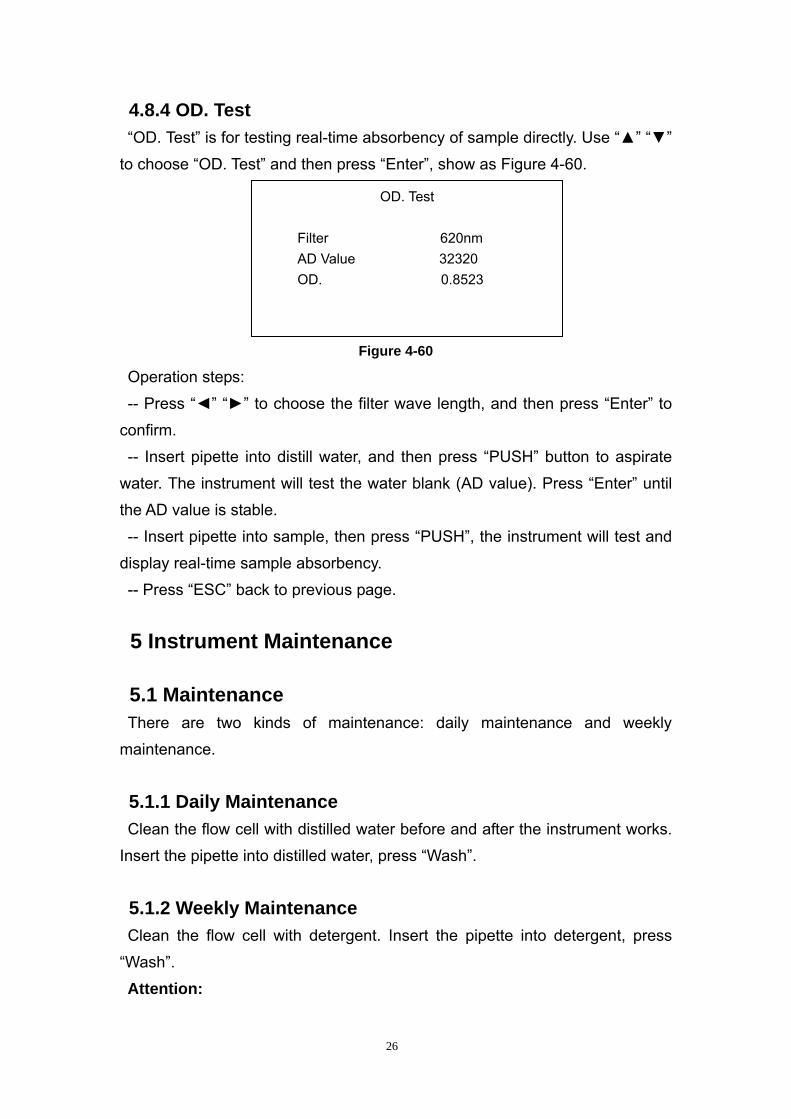
4.8.4 OD. Test “OD. Test” is for testing real-time absorbency of sample directly. Use “▲” “▼”
to choose “OD. Test” and then press “Enter”, show as Figure 4-60.
OD. Test
Filter 620nm AD Value 32320 OD. 0.8523
Figure 4-60
Operation steps:
-- Press “◄” “►” to choose the filter wave length, and then press “Enter” to
confirm.
-- Insert pipette into distill water, and then press “PUSH” button to aspirate
water. The instrument will test the water blank (AD value). Press “Enter” until
the AD value is stable.
-- Insert pipette into sample, then press “PUSH”, the instrument will test and
display real-time sample absorbency.
-- Press “ESC” back to previous page.
5 Instrument Maintenance
5.1 Maintenance There are two kinds of maintenance: daily maintenance and weekly
maintenance.
5.1.1 Daily Maintenance
Clean the flow cell with distilled water before and after the instrument works.
Insert the pipette into distilled water, press “Wash”.
5.1.2 Weekly Maintenance
Clean the flow cell with detergent. Insert the pipette into detergent, press
“Wash”.
Attention:
26
-- Detergent should remain in flow cell for about 5-10 minutes. The following
detergents are recommended: 20% NaCLO, 95% absolute alcohol and Special
detergent.
-- If the analyzer stands idle for long time, loose the peristaltic pump tube and
turn on the analyzer every week.
5.2 Trouble Shooting 5.2.1 A/D value of 0 -- The lamp is damaged or the voltage is too low
-- The lamp connection is loose contact
-- Filters have loose contact
-- Filters are damaged
5.2.2 AD value out of range -- There is no distilled water in flow cell
-- Flow cell is dirty
-- There is bubble in flow cell
-- Pipette is leaked or blocked.
-- Peristalsis pump hitch
-- Filter is aging or damaged
5.2.3 Wrong test result or bad repetition -- There is bubble in flow cell
-- Peristalsis pump tube is not installed properly or leaked.
--Aspiration is abnormal.
-- Voltage is not stable
-- The sample is haemolytic or the reagent is invalid.
Attention: If there are some problems cannot be resolved, please contact
Clindiag distributor and engineer
27
5.3 Fittings Replacement 5.3.1 Power Supply Fuse -- Turn off power supply, and unplug power supply line.
-- On the right underside of the instrument, pull out fuse under the socket.
-- Replace old fuse with a new one
5.3.2 Peristalsis Pump Tube Replacement -- Open the cover on the instrument side face.
-- Pull out the pump tube.
-- Replace with the new pump tube
5.3.3 Printing Paper Replacement -- Open printer cover; take away the old printing paper
-- Load the new printing paper into the paper slot
-- Put the paper to the form feed
-- Press “Feed”
Attention: If there are some problems cannot be resolved, please contact
Clindiag distributor and engineer
6 Storage Packed instruments should be placed in the well-ventilated room, avoiding
hard by poisonous, harmful and corrosive substances.
End
28
CLINDIAG SYSTEMS USA