Embed Size (px)
Citation preview

7/30/2019 Manual de Servicio2 Bizhub 160
http://slidepdf.com/reader/full/manual-de-servicio2-bizhub-160 1/313
SERVICE MANUAL
2005.042005.04
Ver. 1.0Ver. 1.0
FIELD SERVICE

7/30/2019 Manual de Servicio2 Bizhub 160
http://slidepdf.com/reader/full/manual-de-servicio2-bizhub-160 2/313
SAFETY AND IMPORTANT WARNING ITEMS
S-1
Read carefully the Safety and Important Warning Items described below to understand
them before doing service work.
Because of possible hazards to an inexperienced person servicing this product as well as
the risk of damage to the product, KONICA MINOLTA BUSINESS TECHNOLOGIES, INC.
(hereafter called the KMBT) strongly recommends that all servicing be performed only by
KMBT-trained service technicians.
Changes may have been made to this product to improve its performance after this Service
Manual was printed. Accordingly, KMBT does not warrant, either explicitly or implicitly, that
the information contained in this Service Manual is complete and accurate.
The user of this Service Manual must assume all risks of personal injury and/or damage to
the product while servicing the product for which this Service Manual is intended.
Therefore, this Service Manual must be carefully read before doing service work both in thecourse of technical training and even after that, for performing maintenance and control of
the product properly.
Keep this Service Manual also for future service.
In this Service Manual, each of three expressions “ DANGER”, “ WARNING”, and
“ CAUTION” is defined as follows together with a symbol mark to be used in a limited
meaning.When servicing the product, the relevant works (disassembling, reassembling, adjustment,
repair, maintenance, etc.) need to be conducted with utmost care.
Symbols used for safety and important warning items are defined as follows:
SAFETY AND IMPORTANT WARNING ITEMS
IMPORTANT NOTICE
DESCRIPTION ITEMS FOR DANGER,WARNING AND CAUTION
DANGER: Action having a high possibility of suffering death or serious injury
WARNING: Action having a possibility of suffering death or serious injury
CAUTION: Action having a possibility of suffering a slight wound, mediumtrouble, and property damage
:Precaution when servicing the
product. General
precaution
Electric hazard High temperature
:Prohibition when servicing the
product. General
prohibition
Do not touch
with wet hand
Do not
disassemble
:Direction when servicing theproduct. General
instruction
Unplug Ground/Earth

7/30/2019 Manual de Servicio2 Bizhub 160
http://slidepdf.com/reader/full/manual-de-servicio2-bizhub-160 3/313
SAFETY AND IMPORTANT WARNING ITEMS
S-2
[1] MODIFICATIONS NOT AUTHORIZED BY KONICA MINOLTABUSINESS TECHNOLOGIES, INC.
KONICA MINOLTA brand products are renowned for their high reliability. This reliability isachieved through high-quality design and a solid service network.
Product design is a highly complicated and delicate process where numerous mechanical,
physical, and electrical aspects have to be taken into consideration, with the aim of arriving
at proper tolerances and safety factors. For this reason, unauthorized modifications involve
a high risk of degradation in performance and safety. Such modifications are therefore
strictly prohibited. the points listed below are not exhaustive, but they illustrate the reason-
ing behind this policy.
SAFETY WARNINGS
Prohibited Actions
DANGER
• Using any cables or power cord not specified by KMBT.
• Using any fuse or thermostat not specified by KMBT.
Safety will not be assured, leading to a risk of fire and
injury.
• Disabling fuse functions or bridging fuse terminals with
wire, metal clips, solder or similar object.
• Disabling relay functions (such as wedging paper between
relay contacts)
• Disabling safety functions (interlocks, safety circuits, etc.)
Safety will not be assured, leading to a risk of fire and
injury.
• Making any modification to the product unless instructed
by KMBT
• Using parts not specified by KMBT

7/30/2019 Manual de Servicio2 Bizhub 160
http://slidepdf.com/reader/full/manual-de-servicio2-bizhub-160 4/313
SAFETY AND IMPORTANT WARNING ITEMS
S-3
[2] POWER PLUG SELECTION
In some countries or areas, the power plug provided with the product may not fit wall outlet
used in the area. In that case, it is obligation of customer engineer (hereafter called the CE)
to attach appropriate power plug or power cord set in order to connect the product to the
supply.
Power Cord Set or Power PlugWARNING
• Use power supply cord set which meets the following
criteria:
- provided with a plug having configuration intended for
the connection to wall outlet appropriate for the prod-
uct's rated voltage and current, and
- the plug has pin/terminal(s) for grounding, and
- provided with three-conductor cable having enough cur-
rent capacity, and
- the cord set meets regulatory requirements for the area.
Use of inadequate cord set leads to fire or electric shock.
• Attach power plug which meets the following criteria:
- having configuration intended for the connection to wall
outlet appropriate for the product's rated voltage and
current, and
- the plug has pin/terminal(s) for grounding, and- meets regulatory requirements for the area.
Use of inadequate cord set leads to the product connect-
ing to inadequate power supply (voltage, current capacity,
grounding), and may result in fire or electric shock.
• Conductors in the power cable must be connected to ter-
minals of the plug according to the following order:
• Black or Brown: L (line)
• White or Light Blue: N (neutral)
• Green/Yellow: PE (earth)
Wrong connection may cancel safeguards within the
product, and results in fire or electric shock.
kw

7/30/2019 Manual de Servicio2 Bizhub 160
http://slidepdf.com/reader/full/manual-de-servicio2-bizhub-160 5/313
SAFETY AND IMPORTANT WARNING ITEMS
S-4
[3] CHECKPOINTS WHEN PERFORMING ON-SITE SERVICE
KONICA MINOLTA brand products are extensively tested before shipping, to ensure that all
applicable safety standards are met, in order to protect the customer and customer engi-
neer (hereafter called the CE) from the risk of injury. However, in daily use, any electrical
equipment may be subject to parts wear and eventual failure. In order to maintain safety
and reliability, the CE must perform regular safety checks.
1. Power Supply
Connection to Power Supply
WARNING
• Check that mains voltage is as specified.
Connection to wrong voltage supply may result in fire or
electric shock.
• Connect power plug directly into wall outlet having same
configuration as the plug.
Use of an adapter leads to the product connecting to
inadequate power supply (voltage, current capacity,
grounding), and may result in fire or electric shock.
If proper wall outlet is not available, advice the customer
to contact qualified electrician for the installation.
• Plug the power cord into the dedicated wall outlet with a
capacity greater than the maximum power consumption.
If excessive current flows in the wall outlet, fire may
result.
• If two or more power cords can be plugged into the wall
outlet, the total load must not exceed the rating of the wall
outlet.
If excessive current flows in the wall outlet, fire may
result.
• Make sure the power cord is plugged in the wall outlet
securely.
Contact problems may lead to increased resistance,
overheating, and the risk of fire.
• Check whether the product is grounded properly.
If current leakage occurs in an ungrounded product, you
may suffer electric shock while operating the product.
Connect power plug to grounded wall outlet.
kw
7/30/2019 Manual de Servicio2 Bizhub 160
http://slidepdf.com/reader/full/manual-de-servicio2-bizhub-160 6/313
SAFETY AND IMPORTANT WARNING ITEMS
S-5
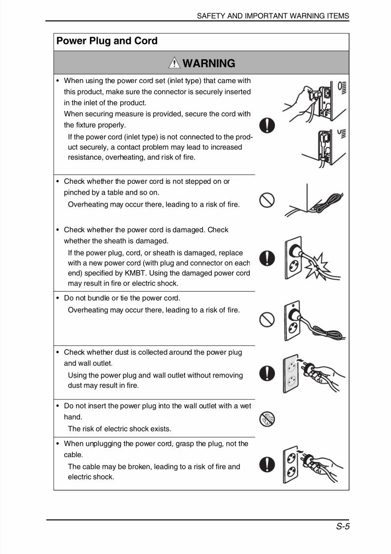
Power Plug and Cord
WARNING
• When using the power cord set (inlet type) that came with
this product, make sure the connector is securely inserted
in the inlet of the product.
When securing measure is provided, secure the cord with
the fixture properly.
If the power cord (inlet type) is not connected to the prod-
uct securely, a contact problem may lead to increased
resistance, overheating, and risk of fire.
• Check whether the power cord is not stepped on or
pinched by a table and so on.Overheating may occur there, leading to a risk of fire.
• Check whether the power cord is damaged. Check
whether the sheath is damaged.
If the power plug, cord, or sheath is damaged, replace
with a new power cord (with plug and connector on each
end) specified by KMBT. Using the damaged power cord
may result in fire or electric shock.
• Do not bundle or tie the power cord.
Overheating may occur there, leading to a risk of fire.
• Check whether dust is collected around the power plug
and wall outlet.
Using the power plug and wall outlet without removing
dust may result in fire.
• Do not insert the power plug into the wall outlet with a wet
hand.
The risk of electric shock exists.
• When unplugging the power cord, grasp the plug, not the
cable.
The cable may be broken, leading to a risk of fire and
electric shock.

7/30/2019 Manual de Servicio2 Bizhub 160
http://slidepdf.com/reader/full/manual-de-servicio2-bizhub-160 7/313
SAFETY AND IMPORTANT WARNING ITEMS
S-6
2. Installation Requirements
Wiring
WARNING
• Never use multi-plug adapters to plug multiple power cords
in the same outlet.
If used, the risk of fire exists.
• When an extension cord is required, use a specified one.
Current that can flow in the extension cord is limited, so
using a too long extension cord may result in fire.
Do not use an extension cable reel with the cable taken
up. Fire may result.
Prohibited Installation Places
WARNING
• Do not place the product near flammable materials or vola-
tile materials that may catch fire.
A risk of fire exists.
• Do not place the product in a place exposed to water such
as rain.
A risk of fire and electric shock exists.
When not Using the Product for a long time
WARNING
• When the product is not used over an extended period oftime (holidays, etc.), switch it off and unplug the power
cord.
Dust collected around the power plug and outlet may
cause fire.

7/30/2019 Manual de Servicio2 Bizhub 160
http://slidepdf.com/reader/full/manual-de-servicio2-bizhub-160 8/313
SAFETY AND IMPORTANT WARNING ITEMS
S-7
Ventilation
CAUTION
• The product generates ozone gas during operation, but it
will not be harmful to the human body.
If a bad smell of ozone is present in the following cases,
ventilate the room.
a. When the product is used in a poorly ventilated room
b. When taking a lot of copies
c. When using multiple products at the same time
Stability
CAUTION• Be sure to lock the caster stoppers.
In the case of an earthquake and so on, the product may
slide, leading to a injury.
Inspection before Servicing
CAUTION
• Before conducting an inspection, read all relevant docu-
mentation (service manual, technical notices, etc.) and
proceed with the inspection following the prescribed pro-
cedure, using only the prescribed tools. Do not make any
adjustment not described in the documentation.
If the prescribed procedure or tool is not used, the prod-
uct may break and a risk of injury or fire exists.
• Before conducting an inspection, be sure to disconnect
the power plugs from the product and options.
When the power plug is inserted in the wall outlet, some
units are still powered even if the POWER switch is
turned OFF. A risk of electric shock exists.
• The area around the fixing unit is hot.
You may get burnt.

7/30/2019 Manual de Servicio2 Bizhub 160
http://slidepdf.com/reader/full/manual-de-servicio2-bizhub-160 9/313
SAFETY AND IMPORTANT WARNING ITEMS
S-8
Work Performed with the Product Powered On
WARNING
• Take every care when making adjustments or performing
an operation check with the product powered.
If you make adjustments or perform an operation check
with the external cover detached, you may touch live or
high-voltage parts or you may be caught in moving gears
or the timing belt, leading to a risk of injury.
• Take every care when servicing with the external cover
detached.
High-voltage exists around the drum unit. A risk of elec-
tric shock exists.
Safety Checkpoints
WARNING
• Check the exterior and frame for edges, burrs, and other
damage.
The user or CE may be injured.
• Do not allow any metal parts such as clips, staples, andscrews to fall into the product.
They can short internal circuits and cause electric shock
or fire.
• Check wiring for squeezing and any other damage.
Current can leak, leading to a risk of electric shock or
fire.
• Carefully remove all toner remnants and dust from electri-
cal parts and electrode units such as a charging coronaunit.
Current can leak, leading to a risk of product trouble or
fire.
• Check high-voltage cables and sheaths for any damage.
Current can leak, leading to a risk of electric shock or
fire.

7/30/2019 Manual de Servicio2 Bizhub 160
http://slidepdf.com/reader/full/manual-de-servicio2-bizhub-160 10/313
SAFETY AND IMPORTANT WARNING ITEMS
S-9
• Check electrode units such as a charging corona unit for
deterioration and sign of leakage.
Current can leak, leading to a risk of trouble or fire.
• Before disassembling or adjusting the write unit (P/H unit)
incorporating a laser, make sure that the power cord has
been disconnected.
The laser light can enter your eye, leading to a risk of
loss of eyesight.
• Do not remove the cover of the write unit. Do not supply
power with the write unit shifted from the specified mount-
ing position.
The laser light can enter your eye, leading to a risk of
loss of eyesight.
• When replacing a lithium battery, replace it with a new lith-
ium battery specified in the Parts Guide Manual. Dispose
of the used lithium battery using the method specified by
local authority.
Improper replacement can cause explosion.
• After replacing a part to which AC voltage is applied (e.g.,
optical lamp and fixing lamp), be sure to check the installa-
tion state.
A risk of fire exists.
• Check the interlock switch and actuator for loosening and
check whether the interlock functions properly.
If the interlock does not function, you may receive an
electric shock or be injured when you insert your hand in
the product (e.g., for clearing paper jam).
• Make sure the wiring cannot come into contact with sharp
edges, burrs, or other pointed parts.
Current can leak, leading to a risk of electric shock or
fire.
Safety Checkpoints
WARNING

7/30/2019 Manual de Servicio2 Bizhub 160
http://slidepdf.com/reader/full/manual-de-servicio2-bizhub-160 11/313
SAFETY AND IMPORTANT WARNING ITEMS
S-10
• Make sure that all screws, components, wiring, connec-
tors, etc. that were removed for safety check and mainte-
nance have been reinstalled in the original location. (Pay
special attention to forgotten connectors, pinched cables,
forgotten screws, etc.)
A risk of product trouble, electric shock, and fire exists.
Safety Checkpoints
WARNING
Handling of Consumables
WARNING
• Toner and developer are not harmful substances, but care
must be taken not to breathe excessive amounts or let the
substances come into contact with eyes, etc. It may be
stimulative.
If the substances get in the eye, rinse with plenty of water
immediately. When symptoms are noticeable, consult a
physician.
• Never throw the used cartridge and toner into fire.
You may be burned due to dust explosion.
Handling of Service Materials
CAUTION
• Unplug the power cord from the wall outlet.Drum cleaner (isopropyl alcohol) and roller cleaner (ace-
tone-based) are highly flammable and must be handled
with care. A risk of fire exists.
• Do not replace the cover or turn the product ON before
any solvent remnants on the cleaned parts have fully
evaporated.
A risk of fire exists.
7/30/2019 Manual de Servicio2 Bizhub 160
http://slidepdf.com/reader/full/manual-de-servicio2-bizhub-160 12/313
SAFETY AND IMPORTANT WARNING ITEMS
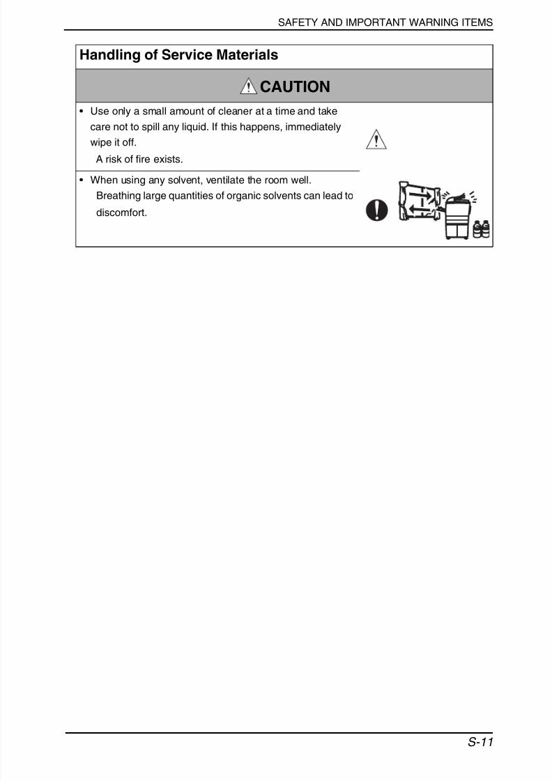
S-11
• Use only a small amount of cleaner at a time and take
care not to spill any liquid. If this happens, immediately
wipe it off.
A risk of fire exists.
• When using any solvent, ventilate the room well.
Breathing large quantities of organic solvents can lead to
discomfort.
Handling of Service Materials
CAUTION

7/30/2019 Manual de Servicio2 Bizhub 160
http://slidepdf.com/reader/full/manual-de-servicio2-bizhub-160 13/313
SAFETY AND IMPORTANT WARNING ITEMS
S-12
[4] Laser Safety
• This is a digital machine certified as a Class 1 laser product. There is no possibility of
danger from a laser, provided the machine is serviced according to the instruction in this
manual.
4.1 Internal Laser Radiation
*at laser aperture of the Print Head Unit
• This product employs a Class 3b laser diode that emits an invisible laser beam. The laser
diode and the scanning polygon mirror are incorporated in the print head unit.
• The print head unit is NOT A FIELD SERVICEABLE ITEM. Therefore, the print head unit
should not be opened under any circumstances.
semiconductor laser
Maximum power of the laser diode 15 mW
Maximum average radiation power (*) 36.903 µW
Wavelength 770-800 nm
Laser Aperture ofthe Print Head Unit
C4980o053AB

7/30/2019 Manual de Servicio2 Bizhub 160
http://slidepdf.com/reader/full/manual-de-servicio2-bizhub-160 14/313
SAFETY AND IMPORTANT WARNING ITEMS
S-13
[5] Used Batteries Precautions
ALL Areas
CAUTION
Danger of explosion if battery is incorrectly replaced.
Replace only with the same or equivalent type recommended by the manufacturer.
Dispose of used batteries according to the manufacturer’s instructions.
Germany
VORSICHT!
Explosionsgefahr bei unsachgemäßem Austausch der Batterie.
Ersatz nur durch denselben oder einen vom Hersteller empfohlenen gleichwertigen Typ.
Entsorgung gebrauchter Batterien nach Angaben des Herstellers.
France
ATTENTIONIl y a danger d’explosion s’il y a remplacement incorrect de la batterie.
Remplacer uniquement avec une batterie du même type ou d’un type équivalent recom-
mandé par le constructeur. Mettre au rebut les batteries usagées conformément aux
instructions du fabricant.
Denmark
ADVARSEL!
Lithiumbatteri - Eksplosionsfare ved fejlagtig håndtering.
Udskiftning må kun ske med batteri af samme fabrikat og type. Levér det brugte batteri til-bage til leverandøren.
Finland, Sweden
VAROlTUS
Paristo voi räjähtää, jos se on virheellisesti asennettu.
Vaihda paristo ainoastaan laitevalmistajan suosittelemaan tyyppiin. Hävitä käytetty paristo
valmistajan ohjeiden mukaisesti.
VARNING
Explosionsfara vid felaktigt batteribyte.Använd samma batterityp eller en ekvivalent typ som rekommenderas av apparat-
tillverkaren. Kassera använt batteri enligt fabrikantens instruktion.
Norway
ADVARSEL
Eksplosjonsfare ved feilaktig skifte av batteri.
Benytt samme batteritype eller en tilsvarende type anbefalt av apparatfabrikanten. Brukte
batterier kasseres i henhold til fabrikantens instruksjoner.

7/30/2019 Manual de Servicio2 Bizhub 160
http://slidepdf.com/reader/full/manual-de-servicio2-bizhub-160 15/313
SAFETY AND IMPORTANT WARNING ITEMS
S-14
U.S.A., Canada(CDRH Regulation)• This machine is certified as a Class 1 Laser product under Radiation Performance Stan-
dard according to the Food, Drug and Cosmetic Act of 1990. Compliance is mandatory
for Laser products marketed in the United States and is reported to the Center for
Devices and Radiological Health (CDRH) of the U.S. Food and Drug Administration of
the U.S. Department of Health and Human Services (DHHS). This means that the device
does not produce hazardous laser radiation.
• The label shown on page S-16 indicates compliance with the CDRH regulations and
must be attached to laser products marketed in the United States.
All Areas
Denmark
CAUTION Use of controls, adjustments or performance of procedures other than those
specified in this manual may result in hazardous radiation exposure.
semiconductor laser
Maximum power of the laser diode 15 mW
Wavelength 770-800 nm
CAUTION• Use of controls, adjustments or performance of procedures other than those
specified in this manual may result in hazardous radiation exposure.
semiconductor laser
Maximum power of the laser diode 15 mW
Wavelength 770-800 nm
ADVARSEL• Usynlig laserstråling ved åbning, når sikkerhedsafbrydere er ude af funktion.
Undgå udsættelse for stråling. Klasse 1 laser produkt der opfylder IEC60825-1sikkerheds kravene.
halvlederlaser
Laserdiodens højeste styrke 15 mW
bølgelængden 770-800 nm

7/30/2019 Manual de Servicio2 Bizhub 160
http://slidepdf.com/reader/full/manual-de-servicio2-bizhub-160 16/313
SAFETY AND IMPORTANT WARNING ITEMS
S-15
Finland, Sweden
Norway
LUOKAN 1 LASERLAITEKLASS 1 LASER APPARAT
VAROITUS!
• Laitteen käyttäminen muulla kuin tässä käyttöohjeessa mainitulla tavalla saat-taa altistaa käyttäjän turvallisuusluokan 1 ylittävälle näkymättömälle laser-säteilylle.
puolijohdelaser
Laserdiodin suurin teho 15 mW
aallonpituus 770-800 nm
VARNING!
• Om apparaten används på annat sätt än i denna bruksanvisning specificerats,kan användaren utsättas för osynlig laserstrålning, som överskrider gränsen förlaserklass 1.
halvledarlaser
Den maximala effekten för laserdioden 15 mW
våglängden 770-800 nm
VARO!• Avattaessa ja suojalukitus ohitettaessa olet alttiina näkymättomälle laser-
säteilylle. Älä katso säteeseen.
VARNING!• Osynlig laserstråining när denna del är öppnad och spärren är urkopplad.
Betrakta ej stråien.
ADVERSEL• Dersom apparatet brukes på annen måte enn spesifisert i denne bruksanvisn-
ing, kan brukeren utsettes för unsynlig laserstrålning, som overskrider grensenfor laser klass 1.
halvleder laser
Maksimal effekt till laserdiode 15 mW
bølgelengde 770-800 nm

7/30/2019 Manual de Servicio2 Bizhub 160
http://slidepdf.com/reader/full/manual-de-servicio2-bizhub-160 17/313
SAFETY AND IMPORTANT WARNING ITEMS
S-16
5.1 Laser Safety Label
• A laser safety label is attached to the inside of the machine as shown below.
5.2 Laser Caution Label
• A laser caution label is attached to the outside of the machine as shown below.
4980D070AB
4980D061AA

7/30/2019 Manual de Servicio2 Bizhub 160
http://slidepdf.com/reader/full/manual-de-servicio2-bizhub-160 18/313
SAFETY AND IMPORTANT WARNING ITEMS
S-17
5.3 PRECAUTIONS FOR HANDLING THE LASER EQUIPMENT
• When laser protective goggles are to be used, select ones with a lens conforming to the
above specifications.
• When a disassembly job needs to be performed in the laser beam path, such as when
working around the printerhead and PC Drum, be sure first to turn the printer OFF.
• If the job requires that the printer be left ON, take off your watch and ring and wear laser
protective goggles.• A highly reflective tool can be dangerous if it is brought into the laser beam path. Use
utmost care when handling tools on the user’s premises.
• The Print Head is not to be disassembled or adjusted in the field. Replace the Unit or
Assembly including the Control Board. Therefore, remove the Laser Diode, and do not
perform Control Board trimmer adjustment.
7/30/2019 Manual de Servicio2 Bizhub 160
http://slidepdf.com/reader/full/manual-de-servicio2-bizhub-160 19/313
SAFETY AND IMPORTANT WARNING ITEMS
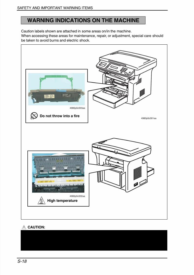
S-18
Caution labels shown are attached in some areas on/in the machine.
When accessing these areas for maintenance, repair, or adjustment, special care should
be taken to avoid burns and electric shock.
CAUTION:
WARNING INDICATIONS ON THE MACHINE
4980p0c001aa
4980p0c002aa
4980p0c003aa
High temperature
Do not throw into a fire
• You may be burned or injured if you touch any area that you are advised not totouch by any caution label. Do not remove caution labels. If any caution label hascome off or become dirty and therefore the caution cannot be read, contact ourService Office.

7/30/2019 Manual de Servicio2 Bizhub 160
http://slidepdf.com/reader/full/manual-de-servicio2-bizhub-160 20/313
SERVICE MANUAL
2005.04
Ver. 1.0
FIELD SERVICE
Main Unit

7/30/2019 Manual de Servicio2 Bizhub 160
http://slidepdf.com/reader/full/manual-de-servicio2-bizhub-160 21/313

7/30/2019 Manual de Servicio2 Bizhub 160
http://slidepdf.com/reader/full/manual-de-servicio2-bizhub-160 22/313
After publication of this service manual, the parts and mechanism may be subject to change for
improvement of their performance.
Therefore, the descriptions given in this service manual may not coincide with the actual machine.
When any change has been made to the descriptions in the service manual, a revised version will be
issued with a revision mark added as required.
Revision mark:
• To indicate clearly a section revised, show to the left of the revised section.
A number within represents the number of times the revision has been made.
• To indicate clearly a section revised, show in the lower outside section of the correspond-
ing page.
A number within represents the number of times the revision has been made.
NOTERevision marks shown in a page are restricted only to the latest ones with the old ones deleted.
• When a page revised in Ver. 2.0 has been changed in Ver. 3.0:
The revision marks for Ver. 3.0 only are shown with those for Ver. 2.0 deleted.
• When a page revised in Ver. 2.0 has not been changed in Ver. 3.0:
The revision marks for Ver. 2.0 are left as they are.
1
1
1
1
2005/04 1.0 — Issue of the first edition
Date Service manual Ver. Revision mark Descriptions of revision

7/30/2019 Manual de Servicio2 Bizhub 160
http://slidepdf.com/reader/full/manual-de-servicio2-bizhub-160 23/313

7/30/2019 Manual de Servicio2 Bizhub 160
http://slidepdf.com/reader/full/manual-de-servicio2-bizhub-160 24/313
b i z h u b 1 6 0 / 1 6 0 f
b i z h u b 1 6 1 / 1 6 1 f
G e n e r a l
M a i n t e n a n c e
A d j u s t m e n t / S e t t i n g
T r o u b l e s h o o t i n g
A p p e n d i x
Field Service Ver. 1.0 Apr. 2005
i
CONTENTS
General1. System configuration............................................................................................... 1
2. Product specifications .............................................................................................2
2.1 bizhub 160 / bizhub 161 ....................................................................................... 2
2.1.1 Main Unit ....................................................................................................... 2
2.1.2 GDI Printer Function (bizhub 160 only).........................................................4
2.1.3 PCL Printer Function (bizhub 161 only)........................................................5
2.2 bizhub 160f / bizhub 161f ..................................................................................... 6
2.2.1 Main Unit ....................................................................................................... 6
2.2.2 GDI Printer Function (bizhub 160f only)........................................................ 8
2.2.3 PCL Printer Function (bizhub 161f only)....................................................... 9
2.2.4 FAX Function...............................................................................................10
Maintenance3. Periodical check .................................................................................................... 13
3.1 Maintenance Items .............................................................................................13
3.1.1 Parts to be Replaced by Users (CRU) ........................................................ 13
3.1.2 Periodical Parts Replacement (Every 50,000 Print)....................................13
3.2 Maintenance Parts.............................................................................................. 143.3 Concept of parts life............................................................................................ 14
3.4 Maintenance procedure (Periodical check parts) ...............................................15
3.4.1 Remove the Imaging Cartridge................................................................... 15
3.4.2 Feed Roller..................................................................................................15
3.4.3 Replacement of the Image Transfer Roller..................................................16
3.5 Replacing the Unit .............................................................................................. 17
3.5.1 Replacement of the Toner Cartridge........................................................... 17
3.5.2 Replacement of the Drum Cartridge ........................................................... 18
3.5.3 Replacement of the Fusing Unit.................................................................. 19
4. Service tool ........................................................................................................... 21
4.1 CE Tool List......................................................................................................... 21
4.2 Copy materials.................................................................................................... 21
4.2.1 Maintenance Kit ..........................................................................................21
5. Firmware upgrade ................................................................................................. 22
5.1 Preparations for Firmware rewriting.................................................................... 22
5.2 Firmware rewriting .............................................................................................. 22
5.2.1 Installing the Printer Driver/ TWAIN Driver Using Plug and Play ................ 22
7/30/2019 Manual de Servicio2 Bizhub 160
http://slidepdf.com/reader/full/manual-de-servicio2-bizhub-160 25/313
b i z h u b 1 6 1 / 1 6 1 f
G e n e r a l
M a i n t e n a n c e
A d j u s t m e n t / S e t t i n g
T r o u b l e s h o o t i n g
A p p e n d i x
Field Service Ver. 1.0 Apr. 2005
ii
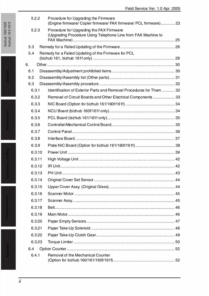
5.2.2 Procedure for Upgrading the Firmware
(Engine firmware/ Copier firmware/ FAX firmware/ PCL firmware)............. 23
5.2.3 Procedure for Upgrading the FAX Firmware
(Upgrading Procedure Using Telephone Line from FAX Machine to
FAX Machine) ............................................................................................. 25
5.3 Remedy for a Failed Updating of the Firmware.................................................. 26
5.4 Remedy for a Failed Updating of the Firmware for PCL
(bizhub 161, bizhub 161f only) ........................................................................... 28
6. Other ..................................................................................................................... 30
6.1 Disassembly/Adjustment prohibited items.......................................................... 30
6.2 Disassembly/Assembly list (Other parts)............................................................ 31
6.3 Disassembly/Assembly procedure ..................................................................... 32
6.3.1 Identification of Exterior Parts and Removal Procedures for Them ............ 32
6.3.2 Removal of Circuit Boards and Other Electrical Components .................... 33
6.3.3 NIC Board (Option for bizhub 161/160f/161f) ............................................. 34
6.3.4 NCU Board (bizhub 160f/161f only)............................................................ 34
6.3.5 PCL Board (bizhub 161/161f only).............................................................. 35
6.3.6 Controller/Mechanical Control Board.......................................................... 35
6.3.7 Control Panel .............................................................................................. 36
6.3.8 Interface Board ........................................................................................... 37
6.3.9 Plate NIC Board (Option for bizhub 161/160f/161f) .................................... 38
6.3.10 Power Unit .................................................................................................. 39
6.3.11 High Voltage Unit ........................................................................................ 42
6.3.12 IR Unit......................................................................................................... 42
6.3.13 PH Unit ....................................................................................................... 43
6.3.14 Original Cover Set Sensor .......................................................................... 44
6.3.15 Upper Cover Assy. (Original Glass) ............................................................ 44
6.3.16 Scanner Motor ............................................................................................ 45
6.3.17 Scanner Assy. ............................................................................................. 45
6.3.18 Belt.............................................................................................................. 46
6.3.19 Main Motor.................................................................................................. 46
6.3.20 Paper Empty Sensors................................................................................. 47
6.3.21 Paper Take-Up Solenoid ............................................................................. 48
6.3.22 Paper Take-Up Clutch Gear........................................................................ 49
6.3.23 Torque Limiter ............................................................................................. 50
6.4 Option Counter ................................................................................................... 52
6.4.1 Removal of the Mechanical Counter
(Option for bizhub 160/161/160f/161f) ........................................................ 52

7/30/2019 Manual de Servicio2 Bizhub 160
http://slidepdf.com/reader/full/manual-de-servicio2-bizhub-160 26/313
b i z h u b 1 6 0 / 1 6 0 f
b i z h u b 1 6 1 / 1 6 1 f
G e n e r a l
M a i n t e n a n c e
A d j u s t m e n t / S e t t i n g
T r o u b l e s h o o t i n g
A p p e n d i x
Field Service Ver. 1.0 Apr. 2005
iii
Adjustment/Setting7. How to use the adjustment section ....................................................................... 53
8. Status Mode.......................................................................................................... 54
8.1 Status Mode function tree................................................................................... 54
8.2 Status Mode setting procedure........................................................................... 55
8.2.1 Procedure ...................................................................................................55
8.2.2 Exiting procedure........................................................................................ 55
8.2.3 Changing the Status Mode functions .......................................................... 55
8.2.4 TOTAL PAGE............................................................................................... 56
8.2.5 TX/ RX RESULT (bizhub 160f/161f only) .................................................... 56
8.2.6 PRINT REPORT (bizhub 161/160f/161f only)............................................. 57
9. Utility Mode (bizhub 160/bizhub 161).................................................................... 64
9.1 Utility Mode function tree ....................................................................................64
9.2 Utility Mode setting procedure ............................................................................ 65
9.2.1 Procedure ...................................................................................................65
9.2.2 Exiting procedure........................................................................................ 65
9.2.3 Changing the settings for Utility Mode functions......................................... 65
9.2.4 MACHINE SETTING................................................................................... 66
9.2.5 PAPER SOURCE SETUP...........................................................................67
9.2.6 USER MANAGEMENT ............................................................................... 68
9.2.7 COPY SETTING ......................................................................................... 689.2.8 NETWORK SETTING .................................................................................69
10. Utility Mode (bizhub 160f/bizhub 161f).................................................................. 71
10.1 Utility Mode function tree ....................................................................................71
10.2 Utility Mode setting procedure ............................................................................ 74
10.2.1 Procedure ...................................................................................................74
10.2.2 Exiting procedure........................................................................................74
10.2.3 Changing the settings for Utility Mode Functions........................................ 74
10.2.4 MACHINE SETTING...................................................................................75
10.2.5 PAPER SOURCE SETUP........................................................................... 77
10.2.6 USER MANAGEMENT ............................................................................... 77
10.2.7 ADMIN. MANAGEMENT.............................................................................78
10.2.8 COPY SETTING .........................................................................................80
10.2.9 FAX REGISTRATION.................................................................................. 81
10.2.10 TX OPERATION.......................................................................................... 83
10.2.11 RX OPERATION ......................................................................................... 85
10.2.12 COMM. SETTING....................................................................................... 91
10.2.13 REPORTING............................................................................................... 92

7/30/2019 Manual de Servicio2 Bizhub 160
http://slidepdf.com/reader/full/manual-de-servicio2-bizhub-160 27/313
b i z h u b 1 6 1 / 1 6 1 f
G e n e r a l
M a i n t e n a n c e
A d j u s t m e n t / S e t t i n g
T r o u b l e s h o o t i n g
A p p e n d i x
Field Service Ver. 1.0 Apr. 2005
iv
10.2.14 INITIAL USER DATA................................................................................... 93
10.2.15 NETWORK SETTING................................................................................. 94
10.2.16 E-MAIL SETTING 1 .................................................................................... 96
10.2.17 E-MAIL SETTING 2 .................................................................................... 97
10.2.18 SCAN SETTING ......................................................................................... 99
11. Adjustment item list............................................................................................. 100
12. Service Mode (bizhub 160/bizhub 161) .............................................................. 101
12.1 Service Mode function tree............................................................................... 101
12.2 Service Mode setting procedure....................................................................... 103
12.2.1 Procedure ................................................................................................. 103
12.2.2 Exiting procedure...................................................................................... 103
12.2.3 Changing the settings for Service Mode functions ................................... 103
12.3 Service Mode functions.................................................................................... 104
12.3.1 SERVICE’S CHOICE................................................................................ 104
12.3.2 ADJUST.................................................................................................... 107
12.3.3 COUNTER................................................................................................ 115
12.3.4 DISPLAY................................................................................................... 117
12.3.5 FUNCTION ............................................................................................... 118
12.3.6 FIXED ZOOM CHANGE........................................................................... 120
12.3.7 FACTORY TEST....................................................................................... 120
12.3.8 CLEAR DATA ............................................................................................ 12113. Service Mode (bizhub 160f/bizhub 161f) ............................................................ 122
13.1 Service Mode function tree............................................................................... 122
13.2 Service Mode setting procedure....................................................................... 125
13.2.1 Procedure ................................................................................................. 125
13.2.2 Exiting procedure...................................................................................... 125
13.2.3 Changing the settings for Service Mode functions ................................... 125
13.3 Service Mode functions.................................................................................... 126
13.3.1 SERVICE’S CHOICE................................................................................ 126
13.3.2 ADJUST.................................................................................................... 134
13.3.3 COUNTER................................................................................................ 142
13.3.4 DISPLAY................................................................................................... 144
13.3.5 FUNCTION ............................................................................................... 145
13.3.6 Soft Switch Function................................................................................. 147
13.3.7 REPORT................................................................................................... 148
13.3.8 T.30 PROTOCOL LIST.............................................................................. 152
13.3.9 ADMIN. REGISTRATION (Administrator number registration) ................. 153
13.3.10 FIXED ZOOM CHANGE........................................................................... 154

7/30/2019 Manual de Servicio2 Bizhub 160
http://slidepdf.com/reader/full/manual-de-servicio2-bizhub-160 28/313
b i z h u b 1 6 0 / 1 6 0 f
b i z h u b 1 6 1 / 1 6 1 f
G e n e r a l
M a i n t e n a n c e
A d j u s t m e n t / S e t t i n g
T r o u b l e s h o o t i n g
A p p e n d i x
Field Service Ver. 1.0 Apr. 2005
v
13.3.11 FACTORY TEST ....................................................................................... 154
13.3.12 CLEAR DATA ............................................................................................ 154
14. Board Switch.......................................................................................................160
14.1 Names of control panel parts and their functions ............................................. 160
14.1.1 bizhub 160/ bizhub 161............................................................................. 160
14.1.2 bizhub 160f/ bizhub 161f........................................................................... 161
14.2 Circuit Board Locations..................................................................................... 163
14.2.1 bizhub 160 ................................................................................................ 163
14.2.2 bizhub 161 ................................................................................................ 164
14.2.3 bizhub 160f ............................................................................................... 164
14.2.4 bizhub 161f ............................................................................................... 165
14.3 Functions of switches and parts on PWBs ....................................................... 165
14.3.1 PWB-P (Controller/Mechanical Control Board) ......................................... 165
14.3.2 PWB-IF (Interface Board).......................................................................... 166
14.3.3 NCU (Network Control Unit Board) ........................................................... 166
14.3.4 PCL (PCL Controller Board) ..................................................................... 166
14.3.5 NC-501: PWB- NIC (Network Interface Card Board) ................................ 167
14.3.6 NC-501: NIC-IF (Plate NIC Board)............................................................ 167
14.4 Adjustment of jumper switches on NCU board................................................. 168
15. Security Mode ..................................................................................................... 169
15.1 Security Mode function tree..............................................................................16915.2 Security Mode setting procedure......................................................................169
15.2.1 Procedure ................................................................................................. 169
15.2.2 Exiting Procedure...................................................................................... 169
15.3 Security Mode functions ................................................................................... 169
15.3.1 MACHINE COUNTER............................................................................... 169
16. Soft Switch Set (bizhub 160f/bizhub 161f only)...................................................170
16.1 Description........................................................................................................ 170
16.2 Default setting................................................................................................... 17116.2.1 Country for each Marketing area ..............................................................171
16.3 Default soft switch setting for each market area 1 ............................................ 172
16.4 Default soft switch setting for each market area 2 ............................................ 174
16.5 Default soft switch setting for each market area 3 ............................................ 176
16.6 Default soft switch setting for each market area 4 ............................................ 178
16.7 Soft switch list ................................................................................................... 179
16.8 Soft switch definition......................................................................................... 183
16.8.1 SOFT SWITCH: #01 ................................................................................. 18316.8.2 SOFT SWITCH: #02 ................................................................................. 184
16.8.3 SOFT SWITCH: #03 ................................................................................. 185

7/30/2019 Manual de Servicio2 Bizhub 160
http://slidepdf.com/reader/full/manual-de-servicio2-bizhub-160 29/313
b i z h u b 1 6 1 / 1 6 1 f
G e n e r a l
M a i n t e n a n c e
A d j u s t m e n t / S e t t i n g
T r o u b l e s h o o t i n g
A p p e n d i x
Field Service Ver. 1.0 Apr. 2005
vi
16.8.4 SOFT SWITCH: #04................................................................................. 186
16.8.5 SOFT SWITCH: #05................................................................................. 187
16.8.6 SOFT SWITCH: #06................................................................................. 188
16.8.7 SOFT SWITCH: #07................................................................................. 188
16.8.8 SOFT SWITCH: #08................................................................................. 189
16.8.9 SOFT SWITCH: #09................................................................................. 190
16.8.10 SOFT SWITCH: #10................................................................................. 191
16.8.11 SOFT SWITCH: #11................................................................................. 192
16.8.12 SOFT SWITCH: #12................................................................................. 192
16.8.13 SOFT SWITCH: #13................................................................................. 193
16.8.14 SOFT SWITCH: #14................................................................................. 194
16.8.15 SOFT SWITCH: #15................................................................................. 194
16.8.16 SOFT SWITCH: #16................................................................................. 195
16.8.17 SOFT SWITCH: #17................................................................................. 195
16.8.18 SOFT SWITCH: #18................................................................................. 196
16.8.19 SOFT SWITCH: #19................................................................................. 197
16.8.20 SOFT SWITCH: #20................................................................................. 198
16.8.21 SOFT SWITCH: #21................................................................................. 199
16.8.22 SOFT SWITCH: #22................................................................................. 200
16.8.23 SOFT SWITCH: #23................................................................................. 200
16.8.24 SOFT SWITCH: #24................................................................................. 201
16.8.25 SOFT SWITCH: #25................................................................................. 201
16.8.26 SOFT SWITCH: #26................................................................................. 202
16.8.27 SOFT SWITCH: #27................................................................................. 203
16.8.28 SOFT SWITCH: #28................................................................................. 204
16.8.29 SOFT SWITCH: #29................................................................................. 205
16.8.30 SOFT SWITCH: #30................................................................................. 206
16.8.31 SOFT SWITCH: #31................................................................................. 207
16.8.32 SOFT SWITCH: #32................................................................................. 207
16.8.33 SOFT SWITCH: #33................................................................................. 208
16.8.34 SOFT SWITCH: #34................................................................................. 208
16.8.35 SOFT SWITCH: #35................................................................................. 209
16.8.36 SOFT SWITCH: #36................................................................................. 210
16.8.37 SOFT SWITCH: #37................................................................................. 211
16.8.38 SOFT SWITCH: #38................................................................................. 212
16.8.39 SOFT SWITCH: #39................................................................................. 212
16.8.40 SOFT SWITCH: #40................................................................................. 213

7/30/2019 Manual de Servicio2 Bizhub 160
http://slidepdf.com/reader/full/manual-de-servicio2-bizhub-160 30/313
b i z h u b 1 6 0 / 1 6 0 f
b i z h u b 1 6 1 / 1 6 1 f
G e n e r a l
M a i n t e n a n c e
A d j u s t m e n t / S e t t i n g
T r o u b l e s h o o t i n g
A p p e n d i x
Field Service Ver. 1.0 Apr. 2005
vii
16.8.41 SOFT SWITCH: #41 ................................................................................. 214
16.8.42 SOFT SWITCH: #42 ................................................................................. 215
16.8.43 SOFT SWITCH: #43 ................................................................................. 215
16.8.44 SOFT SWITCH: #44 ................................................................................. 215
16.8.45 SOFT SWITCH: #45 ................................................................................. 216
16.8.46 SOFT SWITCH: #46 ................................................................................. 216
16.8.47 SOFT SWITCH: #47 ................................................................................. 217
16.8.48 SOFT SWITCH: #48 ................................................................................. 217
16.8.49 SOFT SWITCH: #49 ................................................................................. 218
16.8.50 SOFT SWITCH: #50 ................................................................................. 218
16.8.51 SOFT SWITCH: #51 ................................................................................. 219
16.8.52 SOFT SWITCH: #52 ................................................................................. 219
16.8.53 SOFT SWITCH: #53 ................................................................................. 220
16.8.54 SOFT SWITCH: #54 ................................................................................. 220
16.8.55 SOFT SWITCH: #55 ................................................................................. 221
16.8.56 SOFT SWITCH: #56 ................................................................................. 221
16.8.57 SOFT SWITCH: #57 ................................................................................. 221
16.8.58 SOFT SWITCH: #58 ................................................................................. 222
16.8.59 SOFT SWITCH: #59 Part 1....................................................................... 223
16.8.60 SOFT SWITCH: #59 Part 2....................................................................... 224
16.8.61 SOFT SWITCH: #59 Part 3....................................................................... 225
16.8.62 SOFT SWITCH: #60 ................................................................................. 226
16.8.63 SOFT SWITCH: #61 ................................................................................. 226
16.8.64 SOFT SWITCH: #62 ................................................................................. 227
16.8.65 SOFT SWITCH: #63 ................................................................................. 227
16.8.66 SOFT SWITCH: #64 ................................................................................. 228
17. Fax Protocols ...................................................................................................... 229
17.1 G3 ECM (G3 Error Correction Mode) ............................................................... 229
17.2 Line control ....................................................................................................... 230
17.2.1 Procedure of G3 mode communication..................................................... 230
17.3 Table of reference code .................................................................................... 231
17.4 How to analyze the T30 protocol monitor .........................................................232
Troubleshooting18. Introduction ......................................................................................................... 239
18.1 Overall Control Configuration ........................................................................... 23919. Jam display ......................................................................................................... 240
19.1 Misfeed Displays............................................................................................... 240

7/30/2019 Manual de Servicio2 Bizhub 160
http://slidepdf.com/reader/full/manual-de-servicio2-bizhub-160 31/313
b i z h u b 1 6 1 / 1 6 1 f
G e n e r a l
M a i n t e n a n c e
A d j u s t m e n t / S e t t i n g
T r o u b l e s h o o t i n g
A p p e n d i x
Field Service Ver. 1.0 Apr. 2005
viii
19.1.1 Misfeed Display Resetting Procedure....................................................... 240
19.2 Sensor layout.................................................................................................... 241
19.3 Solution ............................................................................................................ 242
19.3.1 Initial Check Items .................................................................................... 242
19.3.2 Paper Take-Up/Transport Misfeed ............................................................ 243
19.3.3 Fusing/Exit Misfeed................................................................................... 244
20. Malfunction code................................................................................................. 245
20.1 Trouble code..................................................................................................... 245
20.1.1 Trouble code list........................................................................................ 245
20.2 Solution ............................................................................................................ 247
20.2.1 C0045: Fuser Fan Motor Error.................................................................. 247
20.2.2 C0210: H.V. Abnormal .............................................................................. 247
20.2.3 C0500: Fuser Warm Up Error................................................................... 248
20.2.4 C0510: Fuser Temperature Low ............................................................... 249
20.2.5 C0520: Fuser Overheat ............................................................................ 250
20.2.6 C0650: Scanner Home Sensor Error........................................................ 250
20.2.7 C1200: ASIC Memory Abnormal .............................................................. 251
20.2.8 C1300: Polygon Mirror Motor Error........................................................... 251
20.2.9 C133B: Communication with Option Error................................................ 252
20.2.10 C133C: Modem Error................................................................................ 252
20.2.11 C133D: ROM Checksum Error ................................................................. 25320.2.12 C13F0: Laser Error ................................................................................... 253
20.2.13 C1468: Parameter Chip Error ................................................................... 254
20.2.14 C14A3: IR Lamp Malfunction.................................................................... 254
21. Power supply trouble........................................................................................... 255
21.1 Power is not turned ON. ................................................................................... 255
22. Image quality problem......................................................................................... 256
22.1 Troubleshooting Image Quality Problems......................................................... 256
22.2 How to Identify Problematic Part ...................................................................... 25622.2.1 Initial Check Items .................................................................................... 256
22.3 Troubleshooting for Specific Image Quality Problems ...................................... 257
22.4 Solution ............................................................................................................ 258
22.4.1 Image Reading System: Blank or Black Prints ......................................... 258
22.4.2 Image Reading System: Low Image Density............................................ 258
22.4.3 Image Reading System: Foggy Background or Rough Image.................. 259
22.4.4 Image Reading System: Black Streaks or Bands..................................... 260
22.4.5 Image Reading System: Black Spots ....................................................... 261
22.4.6 Image Reading System: Blank Streaks or Bands..................................... 262

7/30/2019 Manual de Servicio2 Bizhub 160
http://slidepdf.com/reader/full/manual-de-servicio2-bizhub-160 32/313
b i z h u b 1 6 0 / 1 6 0 f
b i z h u b 1 6 1 / 1 6 1 f
G e n e r a l
M a i n t e n a n c e
A d j u s t m e n t / S e t t i n g
T r o u b l e s h o o t i n g
A p p e n d i x
Field Service Ver. 1.0 Apr. 2005
ix
22.4.7 Image Reading System: Uneven Image ................................................... 263
22.4.8 Printer System: Blank or Black Prints ....................................................... 264
22.4.9 Printer System: Blank Spots ..................................................................... 265
22.4.10 Printer System: Smears on Back.............................................................. 265
22.4.11 Printer System: Low Image Density.......................................................... 266
22.4.12 Printer System: Foggy Background........................................................... 267
22.4.13 Printer System: Blank Streaks or Bands................................................... 267
22.4.14 Printer System: Black Streaks or Bands...................................................268
22.4.15 Printer System: Offset Image.................................................................... 268
22.4.16 Printer System: Uneven Image ................................................................. 269
23. FAX error (bizhub 160f/bizhub 161f only)............................................................270
23.1 Communication Error........................................................................................ 270
23.1.1 Outline....................................................................................................... 270
23.1.2 Error occurring during transmission.......................................................... 270
23.1.3 Error occurring during reception ............................................................... 270
23.2 Error Code........................................................................................................ 271
23.2.1 Reception.................................................................................................. 271
23.2.2 Transmission .............................................................................................273
Appendix
24. Parts layout drawing............................................................................................ 27724.1 Main Unit...........................................................................................................277
24.2 DF-501 (Option)................................................................................................ 278
24.3 PF-501 (Option)................................................................................................279
25. Connector layout drawing.................................................................................... 280
25.1 Main Unit........................................................................................................... 280

7/30/2019 Manual de Servicio2 Bizhub 160
http://slidepdf.com/reader/full/manual-de-servicio2-bizhub-160 33/313

7/30/2019 Manual de Servicio2 Bizhub 160
http://slidepdf.com/reader/full/manual-de-servicio2-bizhub-160 34/313
Field Service Ver. 1.0 Apr. 2005 1. System configuration
1
b i z h u b 1 6 0 / 1 6 0 f
b i z h u b 1 6 1 / 1 6 1 f
G e n e r a l
General
1. System configuration
[1] Automatic Document Feeder DF-501 [5] Mechanical Counter MC-502
[2] Original Cover OC-503 [6] Expansion memory (32 MB) EM-101
[3] Main Unit
bizhub 160, bizhub 160f,
bizhub 161, bizhub 161f
[7] NIC NC-501
- Plate NIC Board
[4] Paper Feed Cassette PF-501 [8] Internet Fax & Network Scan kit SU-502
4980G001AB
51
6
4
3
2
7
7
8

7/30/2019 Manual de Servicio2 Bizhub 160
http://slidepdf.com/reader/full/manual-de-servicio2-bizhub-160 35/313
2. Product specifications Field Service Ver. 1.0 Apr. 2005
2
b i z h u b 1 6 1 / 1 6 1 f
G e n e r a l
2. Product specifications
2.1 bizhub 160 / bizhub 161
2.1.1 Main Unit
Copy Medium
NOTEThe dimension for Tray2 is fixed at A4 or Letter.
Type Desktop
Original scanning system Scanning in main scanning direction with a 3-line color CCD sensor, and
scanning in sub-scanning direction with unit scanning and sheet feed-
through system
Photo conductor type OPC (Organic Photo conductor)
Copying system Electrostatic dry Powdered image transfer to plain paper with laser
Resolution Scan: 600 dpi × 600 dpi
Write: 600 dpi × 600 dpi
Paper feed-in system 2-Way system (Tray1 and Bypass Tray)
*3-Way system is possible if optional PF-501 (Tray2) is installed.
Exposure system Unit scanning slit exposure
Developing system FMT (Fine Micro Toning) single component developing
Drum-charging system Rotating brush with pre-charge film
Image transfer system Roller transfer
Paper separation system Curvature separation + Charge Neutralizing needle
Fusing system Heat roller
Max. Original size Up to A4 or 8.5 × 14 (Legal)
Memory Capacity STD: 16 MB
*48 MB Maximum with 32 MB Option Memory (EM-101)
Paper source Tray1 Bypass Tray Tray2
Type Plain paper
(60 to 90 g/m2, 16 to 24 lb)
A4, A5, B5,
8.5 × 14 (Legal),
8.5 × 11 (Letter),
5.5 × 8.5 (Half Letter),
FLS, 16K
Custom size:
Max. 216 × 356 µµMin. 105 × 148 µµ
A4,
8.5 × 11 (Letter)
Recycled paper
(60 to 90 g/m2, 16 to 24 lb)
Special paper
(91 to 163 g/m2, 24 to 43 lb)
–
Transparencies –
Label sheets –
Envelopes –

7/30/2019 Manual de Servicio2 Bizhub 160
http://slidepdf.com/reader/full/manual-de-servicio2-bizhub-160 36/313
Field Service Ver. 1.0 Apr. 2005 2. Product specifications
3
b i z h u b 1 6 0 / 1 6 0 f
b i z h u b 1 6 1 / 1 6 1 f
G e n e r a l
Zoom Ratios
Power /Current Consumption (main unit only)
Continuous copy speed
(copies/min.)
12 copies/minute
(at full size and 600 dpi × 300 dpi, with ADF)
Continuous print speed
(sheets/min.)
More than 16 sheets/minute
(with plain A4R or Letter R paper)
Warm-up time Less than 25 seconds
(at a room temperature of 23 °C and at the rated voltage)
First print time 16 seconds or less
(at full size and 600 dpi × 300 dpi, with plain A4R or Letter R paper)
First copy time 13 seconds or less
(at full size and 600 dpi × 300 dpi, with plain A4R or Letter R paper)
*If the Start key is pressed more than 3 seconds after opening and clos-
ing the Original Cover or Auto Document Feeder after the engine has
warmed up.
Metric Size Inch Size
Fixed Full size ×1.00 ×1.00
Enlargement ×1.15
×1.41
×2.00
×4.00
×1.29
×1.54
×2.00
×4.00
Reduction ×0.81
×0.70
×0.50
×0.25
×0.78
×0.64
×0.50
×0.25
Variable ×0.25 to ×4.00 (in ×0.01 increments)
Lens Through lens (F=5.0, f=27.195)
Exposure Lamp Cold Cathode Florescent Lamp
Fusing temperature 200 °C
Voltage Maximum power consumption
110 V, 120-127 V 720, 820-880 W
220-240 V 740-850 W
Power source 110 V, 120V-127 V, 220-240 V 50/60 Hz
Main unit dimensions
(including Original Cover)
Width....508 mm (20 inch)
Depth....608 mm (24 inch)
Height....408 mm (16 inch)
Main unit weight 14.9 kg (32.75 lb)

7/30/2019 Manual de Servicio2 Bizhub 160
http://slidepdf.com/reader/full/manual-de-servicio2-bizhub-160 37/313
2. Product specifications Field Service Ver. 1.0 Apr. 2005
4
b i z h u b 1 6 1 / 1 6 1 f
G e n e r a l
2.1.2 GDI Printer Function (bizhub 160 only)
RAM Share with copier.
Interfaces IEEE 1284 (Parallel),
USB Revision 1.1 (except for Windows NT)
Printer Language GDI
Fonts Windows
Supported Operating
Systems
Windows XP (SP2 or later),
Windows server 2003,
Windows 2000 (SP4 or later),
Windows NT Workstation Version 4.0 (SP6a or later),
Windows Me,
Windows 98 (SP1),
Windows 98 Second Edition
Web Browser Internet Explorer 4.0 or later,
Netscape navigator 4.0 or later

7/30/2019 Manual de Servicio2 Bizhub 160
http://slidepdf.com/reader/full/manual-de-servicio2-bizhub-160 38/313
Field Service Ver. 1.0 Apr. 2005 2. Product specifications
5
b i z h u b 1 6 0 / 1 6 0 f
b i z h u b 1 6 1 / 1 6 1 f
G e n e r a l
2.1.3 PCL Printer Function (bizhub 161 only)
Memory capacity 32MB (on board for image processing).
16MB (on board for file system, input buffer).
64MB/ 128MB
(optional, standard DIMM for file system. PC133 is recommended)
Interfaces IEEE 1284 (Parallel),USB Revision 1.1 (except for Windows NT)
Printer Language PJL, PCL5e, PCL-XL 2.1
PCL6 printer controller switches the PDL by PJL command.
Download Fonts PCL6 printer controller supports two kinds of download font format.
Bitmap font format/ True type font format
Resident Font & Symbol Set 8 bitmap font (Standard), 45 scale font (Standard)
Symbol Set List (Total 36)
ISO 8859-1 Latin1/ ISO 8859-2 Latin2/ ISO 8559-9 Latin5/ISO 4/ ISO 6/
ISO 11/ ISO 15/ ISO 17/ ISO 21/ ISO 60/ ISO 69/ PC-8/ PC Turkish / PC-
8 Danish/ Norwegian/ PC-850 /PC-852 / PC-856 (PC-Cyrillic)/ Ventura
International/ Ventura US/ Ventura Math/ Windows 3.0 Latin 1 80H/ Win-
dows 3.1 Latin 1 80H/ Windows 3.1 Latin 2 80H/ Windows 3.1 Latin 5
80H/ Windows 3.1 Baltic 80H/ PS Text/ PS Math/ PI Font/ Roman-8/
Desktop/ Microsoft Publishing/ Math-8/ MC Text ODBH/ Legal/ Symbol/
Wingdings
Typeface List (Total 53)
Courier/ CG Times/ CG Times Bold/ CG Times Italic/ CG Times Bold
Italic/ CG Omega/ CG Omega Bold/ CG Omega Italic/ CG Omega Bold
Italic/ Coronet/ Clarendon Condensed/ Univers Medium/ Univers Bold/
Univers Medium Italic/ Univers Bold Italic/ Univers Medium Condensed/
Univers Bold Condensed/ Univers Medium Condensed Italic/ Univers
Bold Condensed Italic/ Antique Olive/ Antique Olive Bold/ Antique OliveItalic/ Garamond Antiqua/ Garamond Halbfett/ Garamond Kursiv/ Gara-
mond Kursiv Halbfelt/ Marigold/ Albertus Medium/ Abertus Extra Bold/
Arial/ Arial Bold/ Arial Italic/ Arial Bold Italic/ Times New/ Times New
Bold/ Times New Italic/ Times New Bold Italic/ Symbol/ Wingdings/ Cou-
rier Bold/ Courier Italic/ Courier Bold Italic/ Letter Gothic/
Resident Font & Symbol Set Letter Gothic Bold/ Letter Gothic Italic/ Line Printer (ISO 8859-1 Latin1)/
Line Printer (Leagal)/ Line Printer (Roman-8)/ Line Printer (PC-8 Danish/
Norwegian)/ Line Printer (PC-850)/ Line Printer (ISO 8859-2 Latin 2)/
Line Printer (ISO 8859-9 Latin5)/ Line Printer (PC-8)
Supported Operating
Systems
Windows XP,
Windows server 2003,Windows 2000,
Windows NT4.0 (SP6a or later: USB not supported),
Windows Me,
Windows 98 Second Edition

7/30/2019 Manual de Servicio2 Bizhub 160
http://slidepdf.com/reader/full/manual-de-servicio2-bizhub-160 39/313
2. Product specifications Field Service Ver. 1.0 Apr. 2005
6
b i z h u b 1 6 1 / 1 6 1 f
G e n e r a l
2.2 bizhub 160f / bizhub 161f
2.2.1 Main Unit
Copy Medium
NOTEThe dimension for Tray2 is fixed at A4 or Letter.
Type Desktop
Original scanning system Scanning in main scanning direction with a 3-line color CCD sensor, and
scanning in sub-scanning direction with unit scanning and sheet feed-
through system
Photo conductor type OPC (Organic Photo conductor)
Copying system Electrostatic dry Powdered image transfer to plain paper with laser
Resolution Scan: 600 dpi × 600 dpi
Write: 600 dpi × 600 dpi
Paper feed-in system 2-Way system (Tray1 and Bypass Tray)
*3-Way system is possible if optional PF-501 (Tray2) is installed.
Exposure system Unit scanning slit exposure
Developing system FMT (Fine Micro Toning) single component developing
Drum-charging system Rotating brush with pre-charge filmImage transfer system Roller transfer
Paper separation system Curvature separation + Charge Neutralizing needle
Fusing system Heat roller
Max. Original size Up to A4 or 8.5 × 14 (Legal)
Memory Capacity STD: 16 MB (48 MB Maximum with 32 MB Option Memory)
Paper source Tray1 Bypass Tray Tray2
Type Plain paper
(60 to 90 g/m2, 16 to 24 lb)
A4, A5, B5,
8.5 × 14 (Legal),
8.5 × 11 (Letter),
5.5 × 8.5 (Half Letter),
FLS, 16K
Custom size:
Max. 216 × 356 µµMin. 105 × 148 µµ
A4,
8.5 × 11 (Letter)
Recycled paper
(60 to 90 g/m2, 16 to 24 lb)
Special paper
(91 to 163 g/m2, 24 to 43 lb)
–
Transparencies –
Label sheets –
Envelopes –

7/30/2019 Manual de Servicio2 Bizhub 160
http://slidepdf.com/reader/full/manual-de-servicio2-bizhub-160 40/313
Field Service Ver. 1.0 Apr. 2005 2. Product specifications
7
b i z h u b 1 6 0 / 1 6 0 f
b i z h u b 1 6 1 / 1 6 1 f
G e n e r a l
Zoom Ratios
Power /Current Consumption (main unit only)
Continuous copy speed
(copies/min.)
12 copies/minute
(at full size and 600 dpi × 300 dpi)
Continuous print speed
(sheets/min.)
More than 16 sheets/minute
(with plain A4R or Letter R paper)
Warm-up time Less than 25 seconds
(at a room temperature of 23 °C and at the rated voltage)
First print time 16 seconds or less
(at full size and 600 dpi × 300 dpi, with plain A4R or Letter R paper)
First copy time 13 seconds or less
(at full size and 600 dpi × 300 dpi, with plain A4R or Letter R paper)
*If the Start key is pressed more than 3 seconds after opening and clos-
ing the Original Cover or Auto Document Feeder after the engine has
warmed up.
Metric Size Inch Size
Fixed Full size ×1.00 ×1.00
Enlargement ×1.15
×1.41
×2.00
×4.00
×1.29
×1.54
×2.00
×4.00
Reduction ×0.81
×0.70
×0.50
×0.25
×0.78
×0.64
×0.50
×0.25
Variable ×0.25 to ×4.00 (in ×0.01 increments)
Lens Through lens (F=5.0, f=27.195)
Exposure Lamp Cold Cathode Florescent Lamp
Fusing temperature 200 °C
Voltage Maximum power consumption
110 V, 120-127 V 700, 770-880 W
220-240 V 740-830 W
Power source 110 V, 120V-127 V, 220-240 V 50/60 Hz
Dimensions
(including Automatic
Document Feeder)
Width....508 mm (20 inch)
Depth....608 mm (24 inch)
Height....468 mm (16 inch)
Weight
(including Automatic
Document Feeder)
17.3 kg (38.25 lb)

7/30/2019 Manual de Servicio2 Bizhub 160
http://slidepdf.com/reader/full/manual-de-servicio2-bizhub-160 41/313
2. Product specifications Field Service Ver. 1.0 Apr. 2005
8
b i z h u b 1 6 1 / 1 6 1 f
G e n e r a l
2.2.2 GDI Printer Function (bizhub 160f only)
RAM Share with copier.
Interfaces IEEE 1284 (Parallel),
USB Revision 1.1 (except for Windows NT)
Printer Language GDI
Fonts Windows
Supported Operating
Systems
Windows XP (SP2 or later),
Windows server 2003,
Windows 2000 (SP4 or later),
Windows NT Workstation Version 4.0 (SP6a or later),
Windows Me,
Windows 98 (SP1),
Windows 98 Second Edition
Web Browser Internet Explorer 4.0 or later,
Netscape navigator 4.0 or later

7/30/2019 Manual de Servicio2 Bizhub 160
http://slidepdf.com/reader/full/manual-de-servicio2-bizhub-160 42/313
Field Service Ver. 1.0 Apr. 2005 2. Product specifications
9
b i z h u b 1 6 0 / 1 6 0 f
b i z h u b 1 6 1 / 1 6 1 f
G e n e r a l
2.2.3 PCL Printer Function (bizhub 161f only)
Memory capacity 32MB (on board for image processing).
16MB (on board for file system, input buffer).
64MB/ 128MB
(optional, standard DIMM for file system. PC133 is recommended)
Interfaces IEEE 1284 (Parallel),USB Revision 1.1 (except for Windows NT)
Printer Language PJL, PCL5e, PCL-XL 2.1
PCL6 printer controller switches the PDL by PJL command.
Download Fonts PCL6 printer controller supports two kinds of download font format.
Bitmap font format/ True type font format
Resident Font & Symbol Set Symbol Set List (Total 36)
ISO 8859-1 Latin1/ ISO 8859-2 Latin2/ ISO 8559-9 Latin5/ISO 4/ ISO 6/
ISO 11/ ISO 15/ ISO 17/ ISO 21/ ISO 60/ ISO 69/ PC-8/ PC Turkish / PC-
8 Danish/ Norwegian/ PC-850 /PC-852 / PC-856 (PC-Cyrillic)/ Ventura
International/ Ventura US/ Ventura Math/ Windows 3.0 Latin 1 80H/ Win-
dows 3.1 Latin 1 80H/ Windows 3.1 Latin 2 80H/ Windows 3.1 Latin 5
80H/ Windows 3.1 Baltic 80H/ PS Text/ PS Math/ PI Font/ Roman-8/
Desktop/ Microsoft Publishing/ Math-8/ MC Text ODBH/ Legal/ Symbol/
Wingdings
Typeface List (Total 53)
Courier/ CG Times/ CG Times Bold/ CG Times Italic/ CG Times Bold
Italic/ CG Omega/ CG Omega Bold/ CG Omega Italic/ CG Omega Bold
Italic/ Coronet/ Clarendon Condensed/ Univers Medium/ Univers Bold/
Univers Medium Italic/ Univers Bold Italic/ Univers Medium Condensed/
Univers Bold Condensed/ Univers Medium Condensed Italic/ Univers
Bold Condensed Italic/ Antique Olive/ Antique Olive Bold/ Antique Olive
Italic/ Garamond Antiqua/ Garamond Halbfett/ Garamond Kursiv/ Gara-mond Kursiv Halbfelt/ Marigold/ Albertus Medium/ Abertus Extra Bold/
Arial/ Arial Bold/ Arial Italic/ Arial Bold Italic/ Times New/ Times New
Bold/ Times New Italic/ Times New Bold Italic/ Symbol/ Wingdings/ Cou-
rier Bold/ Courier Italic/ Courier Bold Italic/ Letter Gothic/
Resident Font & Symbol Set Letter Gothic Bold/ Letter Gothic Italic/ Line Printer (ISO 8859-1 Latin1)/
Line Printer (Leagal)/ Line Printer (Roman-8)/ Line Printer (PC-8 Danish/
Norwegian)/ Line Printer (PC-850)/ Line Printer (ISO 8859-2 Latin 2)/
Line Printer (ISO 8859-9 Latin5)/ Line Printer (PC-8)
Supported Operating
Systems
Windows XP,
Windows server 2003,
Windows 2000,Windows NT4.0 (SP6a or later: USB not supported),
Windows Me,
Windows 98 Second Edition

7/30/2019 Manual de Servicio2 Bizhub 160
http://slidepdf.com/reader/full/manual-de-servicio2-bizhub-160 43/313
2. Product specifications Field Service Ver. 1.0 Apr. 2005
10
b i z h u b 1 6 1 / 1 6 1 f
G e n e r a l
2.2.4 FAX Function
General
Compatibility Super G3/ G3/ ECM (Error correction mode)
Scanning Resolution STD: CD 8 lines/mm x FD 3.85 lines/mm
Fine: CD 8 lines/mm x FD 7.7 lines/mm
Super Fine: CD 8 lines/mm x FD 15.4 lines/mmLine PSTN/ PBX
Data Transmission Rate 33.6 kbps (V.34 JBIG)
Coding Method MH/ MR/ MMR/ JBIG
Scanning Area Scanning on the original glass
- Metric: A5, A4
- Inch: 5.5 × 8.5 (Half Letter), 8.5 × 11 (Letter), 8.5 × 14 (Legal)
Sheet through scanning
- CD direction: Maximum 215 mm (8.5 inch)
- FD direction: Maximum 1,000 mm (39 inch)
Internet fax Enable when the optional Internet Fax & Network Scan Kit SU-502 isinstalled.
Dialing
Direct dialing Entering the fax number directly using the 10-Key Pad.
One touch dial 15 keys
Speed dial 200 fax numbers
Group dial 15 groups (50 destination/group)
Program dial 4 keys (No. 12, 13, 14, 15)
Other dialing Pause insert, Phone Book dial, On-hook dial,
Automatic redial, Redial, Chain dial, Combination dial
Transmission
Transmission mode ADF TX, Memory TX, Batch TX, Broadcast TX,
Confidential Mailbox TX,
F code TX (SubAddress TX, SID TX), Forward TX
Manual TX, Polling TX, Quick Memory TX, Book TX,
Relay initiate TX, Reservation TX, Timer TX,
TX resolution mode/ TX
image mode
Standard (204 dpi x 98 dpi),
Fine (204 dpi x 196 dpi),
Super fine (204 dpi x 392 dpi),
Standard + halftone (204 dpi x 98 dpi),
Fine + halftone (204 dpi x 196 dpi),Super fine + halftone (204 dpi x 392 dpi)
Receiving
Receiving mode Auto RX, Closed network RX, Confidential Mailbox RX,
Inward Polling RX, Manual RX, Memory RX, Substitute RX,
RX resolution 204 dpi x 98 dpi, 204 dpi x 196 dpi, 204 dpi x 392 dpi
Max. recording paper size A4 or 8.5 × 14 (Legal)
Report Activity report, Back up RAM error report,
G3 protocol monitor report, Memory image print,
Power failure report, Reservation report, RX result report,
Service report, TX result report,List Key setting list, Machine status list, Memory data list,
One-touch dial list, Service data list, Speed dial list,

7/30/2019 Manual de Servicio2 Bizhub 160
http://slidepdf.com/reader/full/manual-de-servicio2-bizhub-160 44/313
Field Service Ver. 1.0 Apr. 2005 2. Product specifications
11
b i z h u b 1 6 0 / 1 6 0 f
b i z h u b 1 6 1 / 1 6 1 f
G e n e r a l
Other Features Automatic paper selection, Backup of memory,
Confirmation of communication result, Daylight saving time,
Date/Time setting, Display of destination station, Footer,
Header, Package reception printing, Pause insert,
Quick memory printing, Remote monitor, RX print cancel,
RX printing mode (100 %reception/ Reception print mode/ Cut mode),
Separate print, Smoothing, Speaker, Time zone,
Tone signal transmission, TX cancel, RX cancel

7/30/2019 Manual de Servicio2 Bizhub 160
http://slidepdf.com/reader/full/manual-de-servicio2-bizhub-160 45/313
2. Product specifications Field Service Ver. 1.0 Apr. 2005
12
b i z h u b 1 6 1 / 1 6 1 f
G e n e r a l
Blank page

7/30/2019 Manual de Servicio2 Bizhub 160
http://slidepdf.com/reader/full/manual-de-servicio2-bizhub-160 46/313
Field Service Ver. 1.0 Apr. 2005 3. Periodical check
13
b i z h u b 1 6 0 / 1 6 0 f
b i z h u b 1 6 1 / 1 6 1 f
M a i n t e n a n c e
Maintenance
3. Periodical check
3.1 Maintenance Items
3.1.1 Parts to be Replaced by Users (CRU)
*1: Average number of print during intermittent printing (2 pages/job)
3.1.2 Periodical Parts Replacement (Every 50,000 Print)
No. Class Parts to be replaced Cycle Clean Replace Descriptions
1 Processing
sections
Toner cartridge 4,300 ● *1
2 Drum Cartridge 16,000 ● *1
No. Class Parts to be replacedNumber of
personnel
Check Clean ReplaceLubri-
cation
Descrip-
tions
1Overall
Paper take-up and
image conditions●
2 Appearance ● ●
3Paper feed
sectionFeed roller ● ●
4Transport
sectionImage Transfer Roller 1 ●
5Fusing
sectionFusing Unit 1 ●
6 DF-501 Paper Separator Pad 1 ●

7/30/2019 Manual de Servicio2 Bizhub 160
http://slidepdf.com/reader/full/manual-de-servicio2-bizhub-160 47/313
3. Periodical check Field Service Ver. 1.0 Apr. 2005
14
b i z h u b 1 6 1 / 1 6 1 f
M a i n t e n a n c e
3.2 Maintenance Parts
• To ensure that the machine produces good copies and to extend its service life, it is rec-
ommended that the maintenance jobs described in this schedule be carried out as
instructed.
• Replace with reference to the numeric values displayed on the PM counter.
A. Main Unit
B. Option
NOTE
• As a rule, the Drum Cartridge and Toner Cartridge are to be replaced by the user.• The contents of the Maintenance List are subject to change without notice.• For the part numbers, see Parts Manual and Parts Modification Notice.
3.3 Concept of parts life
A. Conditions for Life Specifications Values• The life specifications value represents the number of printed pages produced or figures
equivalent to it when given conditions (see the Table given below) are met. It can be
more or less depending on how each individual printer is used.
No.Classifica-
tionParts name
Qua
ntity
Actual
durable
cycle
Pats No. Descriptions
Ref.Page
in this
manual
1
Image
Transfer
section
Image Transfer Roller 1 50,000 4136-4103-XX ☞ 16
2Fusing
section
Fusing Unit (100V)1 50,000
4137-0751-XX☞ 19
Fusing Unit (200V) 4137-0752-XX
3 Processing
section
Toner Cartridge 1 4,300 (materials) ☞ 17
4 Drum Cartridge 1 16,000 (materials) ☞ 18
No.Classifica-
tionParts name
Qua
ntity
Actual
durable
cycle
Pats No. Descriptions
Ref.Page
in this
manual
1 DF-501 Separation Pad 1 50,000 4980-1075-XXDF-501
manual
Print Conditions
Job type Making 2 copies per job
Paper size A4R / Letter R
B/W ratio B/W 6 %

7/30/2019 Manual de Servicio2 Bizhub 160
http://slidepdf.com/reader/full/manual-de-servicio2-bizhub-160 48/313

7/30/2019 Manual de Servicio2 Bizhub 160
http://slidepdf.com/reader/full/manual-de-servicio2-bizhub-160 49/313
3. Periodical check Field Service Ver. 1.0 Apr. 2005
16
b i z h u b 1 6 1 / 1 6 1 f
M a i n t e n a n c e
3.4.3 Replacement of the Image Transfer Roller
1. Remove the Imaging Cartridge.
2. Place the levers of the Bearings
(white) on the right and left ends of
the Image Transfer Roller toward this
side and remove the Image Transfer
Roller from the Image Transfer Rollerholder.
3. Pull out the Bearings on the right and
left ends, and the gear, from the
Image Transfer Roller removed from
its holder. Install the Bearings and
the gear to the new Image Transfer
Roller.
NOTE• Do not touch, or dirty with chemi-cals or toner, the surface of theImage Transfer Roller, as indenta-tions in and dirt on the surface ofthe Image Transfer Roller adverselyaffect the quality of the printedimage.
• When handling the Image TransferRoller, hold onto the shaft andBearings of the roller.
• Do not place a new Image TransferRoller directly on the floor or othersurface.
4. Insert the new Image Transfer Roller
into the Image Transfer Roller holder
and place the levers of the Bearings
into the original upward positions.
4136E018AA
4136E019AB
4136E020AB

7/30/2019 Manual de Servicio2 Bizhub 160
http://slidepdf.com/reader/full/manual-de-servicio2-bizhub-160 50/313

7/30/2019 Manual de Servicio2 Bizhub 160
http://slidepdf.com/reader/full/manual-de-servicio2-bizhub-160 51/313

7/30/2019 Manual de Servicio2 Bizhub 160
http://slidepdf.com/reader/full/manual-de-servicio2-bizhub-160 52/313
Field Service Ver. 1.0 Apr. 2005 3. Periodical check
19
b i z h u b 1 6 0 / 1 6 0 f
b i z h u b 1 6 1 / 1 6 1 f
M a i n t e n a n c e
3.5.3 Replacement of the Fusing Unit
NOTE• Immediately after turning off the printer, the area around the Fusing Unit is
extremely hot. Therefore, in order to reduce the risk of burns, wait until the unithas cooled down before performing any operation.
A. Removal Procedure1. Remove the Rear Cover.☞ 32
2. Remove the NIC Board. (only when the option NC-501 is mounted)
☞ 34
3. Remove the NCU Board. (bizhub 160f/161f only)
☞ 34
4. Remove the PCL Board. (bizhub 161/161f only)
☞ 35
5. Unplug all connector on the Control-ler/Mechanical Control Board.
NOTE• The two connectors marked with
“*” in the illustration are providedfor bizhub 160f/161f only.
6. Remove the two screws, and then
remove the Left Rear Cover.
7. Remove the three screws, and then
remove the Circuit Board and Metal
Bracket.
4980E004AB
* *
4980U044AA
4980E008AA

7/30/2019 Manual de Servicio2 Bizhub 160
http://slidepdf.com/reader/full/manual-de-servicio2-bizhub-160 53/313

7/30/2019 Manual de Servicio2 Bizhub 160
http://slidepdf.com/reader/full/manual-de-servicio2-bizhub-160 54/313

7/30/2019 Manual de Servicio2 Bizhub 160
http://slidepdf.com/reader/full/manual-de-servicio2-bizhub-160 55/313

7/30/2019 Manual de Servicio2 Bizhub 160
http://slidepdf.com/reader/full/manual-de-servicio2-bizhub-160 56/313
Field Service Ver. 1.0 Apr. 2005 5. Firmware upgrade
23
b i z h u b 1 6 0 / 1 6 0 f
b i z h u b 1 6 1 / 1 6 1 f
M a i n t e n a n c e
5. Select “Specify a location”, and then click the [Browse...] button.
6. Specify “\Corresponding_language\Win9X” on the CD-ROM, and then click the [OK]
button.
7. Click the [OK] button, and then continue following the instructions in the dialog boxes
that appear until the “Completing the Found New Hardware Wizard” dialog box
appears.
8. Click the [Finish] button.
9. When the “Found New Hardware Wizard” dialog box appears again, repeat steps 4through 8 to install all drivers.
5.2.2 Procedure for Upgrading the Firmware(Engine firmware/ Copier firmware/ FAX firmware/ PCL firmware)
NOTE• The engine firmware, Copier firmware, FAX firmware and PCL firmware can be
upgraded by using the following procedure.• For the upgrading procedure of NIC firmware, see “NIC NC-501 Upgrading the
Firmware.”
1. Turn on the printer.2. Start up the host computer (Windows 98 or later).
3. Copy the “Update Software” folder and “Update” file to drive C. (Copy them into the
highest directory on drive C.)
4. Use a USB cable to connect the printer to the host computer. (Wait until the hardware is
detected.)
5. Display the “System Properties” dialog box (“Properties” for “My Computer”), click the
“Hardware” tab, click the [Device Manager] button, select “Imaging devices”, and then
check that “KONICA MINOLTA 160 scanner” has been added.
6. Double-click “Update” file in the “Update Software” folder.
The “A3S/A4S Update F/W-VX.XX” dialog box appears.
4980f2e001aa
4980D045AA
4980D047AA

7/30/2019 Manual de Servicio2 Bizhub 160
http://slidepdf.com/reader/full/manual-de-servicio2-bizhub-160 57/313

7/30/2019 Manual de Servicio2 Bizhub 160
http://slidepdf.com/reader/full/manual-de-servicio2-bizhub-160 58/313
Field Service Ver. 1.0 Apr. 2005 5. Firmware upgrade
25
b i z h u b 1 6 0 / 1 6 0 f
b i z h u b 1 6 1 / 1 6 1 f
M a i n t e n a n c e
5.2.3 Procedure for Upgrading the FAX Firmware(Upgrading Procedure Using Telephone Line from FAX Machine to FAXMachine)
NOTE• The firmware transmitter fax machine must be loaded with the latest version of the
firmware. If the firmware is not upgraded, do that by following the “Procedure for
Updating the Firmware” described in the previous section.1. Set the REMOTE MONITOR to “FULL” in ADMIN.MANEGEMENT mode of Utility.
(Firmware receiver fax machine)
2. Set the firmware transmitter fax machine into the Service mode.
Utility, Stop, 0, 0, Stop, 0, 1
3. Select “5. FUNCTION” and then select “UPLOAD FIRMWARE”.
4. Type the telephone number, to which the firmware receiver fax machine is connected.
(The relevant one touch dial number may be used if the telephone number has been
previously programmed in it.)
5. Press the Start key. This starts transfer of the data.
The Message Panel of the transmitter fax machine displays the same screen as thatappearing during ordinary faxing.
When the data transfer is completed, the ordinary standby screen reappears on the
Message Panel.
6. The firmware receiver fax machine receives the firmware data.
The following message appears on the Message Panel, indicating that transfer of firm-
ware data is started.
NOTE• Do not use any of the printer and copier functions until upgrading of firmware is
completed.
7. The following message appears on the Message Panel of the firmware receiver fax
machine, indicating that upgrading of the firmware is completed.
8. Turn OFF and ON the Power Switch of the firmware receiver fax machine.
Data transfer started
Data transfer completed
Approx. 15 min.
4980D514AA
Firmware being uploaded
4980D515AA

7/30/2019 Manual de Servicio2 Bizhub 160
http://slidepdf.com/reader/full/manual-de-servicio2-bizhub-160 59/313
5. Firmware upgrade Field Service Ver. 1.0 Apr. 2005
26
b i z h u b 1 6 1 / 1 6 1 f
M a i n t e n a n c e
5.3 Remedy for a Failed Updating of the Firmware
1. Turn off the printer.
2. Remove the USB cable connecting the printer to the host computer.
3. Remove the Rear Cover.
☞ 32
4. Remove the NIC Board. (only when the option NC-501 is mounted)
☞ 345. Change the settings for jumper switches CJ1 and CJ2 on the Controller/Mechanical
Control Board from “1-2” to “2-3”.
6. Attach Service Download BIOS U19 and U26 to memory sockets U19 and U26 on the
Controller/Mechanical Control Board.
4980D052AA
U19U26
CJ1
CJ2
CJ1
CJ2
PWB-P(Controller/MechanicalControl Board)
4980D069AA
Service Download BIOS U19 and U26(Parts No.: 4980-1157-xx)

7/30/2019 Manual de Servicio2 Bizhub 160
http://slidepdf.com/reader/full/manual-de-servicio2-bizhub-160 60/313
Field Service Ver. 1.0 Apr. 2005 5. Firmware upgrade
27
b i z h u b 1 6 0 / 1 6 0 f
b i z h u b 1 6 1 / 1 6 1 f
M a i n t e n a n c e
7. Use a USB cable to connect the printer to the host computer.
8. Start up the host computer.
9. Turn on the printer. The following message appears in the display.
10. Perform steps 6 through 10 of “Procedure for Upgrading the Firmware” to update the
firmware.
11. Check that the following message appears in the display to indicate that the updating of
the firmware has been completed correctly.
12. Turn off the printer.13. Change the settings for jumper switches CJ1 and CJ2 on the Controller/Mechanical
Control Board from “2-3” to “1-2”. (Return them to their default settings.)
14. Remove Service Download BIOS U19 and U26 from memory sockets U19 and U26 on
the Controller/Mechanical Control Board.
15. Install the NIC Board. (only when the optional NIC Board is mounted)
16. Install the Rear Cover.
17. Turn on the printer.
4980D053AA
4980D051AB

7/30/2019 Manual de Servicio2 Bizhub 160
http://slidepdf.com/reader/full/manual-de-servicio2-bizhub-160 61/313

7/30/2019 Manual de Servicio2 Bizhub 160
http://slidepdf.com/reader/full/manual-de-servicio2-bizhub-160 62/313

7/30/2019 Manual de Servicio2 Bizhub 160
http://slidepdf.com/reader/full/manual-de-servicio2-bizhub-160 63/313
6. Other Field Service Ver. 1.0 Apr. 2005
30
b i z h u b 1 6 1 / 1 6 1 f
M a i n t e n a n c e
6. Other
6.1 Disassembly/Adjustment prohibited items
A. Paint-locked Screws
NOTE• Paint-locked screws show that the assembly or unit secured can only be adjusted
or set at the factory and should not be adjusted, set, or removed in the field.
B. Red Painted Screws
NOTE• When the screws are removed, the red paint is coated on the points where read-
justment is required.• Once the red painted screw is removed or loosened, you should make adjustment.
Accordingly check the adjustment items in operation manual and make necessaryadjustment. Note that when two or more screws are used on the part in questions,only one representative screw may be marked with red paint.
(1) Other Screws not Marked with Red Paint
C. Variable Resistors on Board
NOTE• Do not turn the variable resistors on boards for which no adjusting instructions
are given in Adjustment/Setting.
D. Removal of PWBs
NOTE• When removing a circuit board or other electrical component, refer to “Handling of
PWBs” and follow the corresponding removal procedures.• The removal procedures given in the following omit the removal of connectors and
screws securing the circuit board support or circuit board.• Where it is absolutely necessary to touch the ICs and other electrical components
on the board, be sure to ground your body.
Scanner Assy PH Unit
4980D054AA 4980D014AA

7/30/2019 Manual de Servicio2 Bizhub 160
http://slidepdf.com/reader/full/manual-de-servicio2-bizhub-160 64/313
Field Service Ver. 1.0 Apr. 2005 6. Other
31
b i z h u b 1 6 0 / 1 6 0 f
b i z h u b 1 6 1 / 1 6 1 f
M a i n t e n a n c e
6.2 Disassembly/Assembly list (Other parts)
No. Section Part name Ref.Page
1 Exterior parts Original Cover ☞ 32
2 Exit tray ☞ 32
3 Front Door ☞ 32
4 Tray1 (with Bypass Tray) ☞ 32
5 Left Cover ☞ 32
6 Right Cover ☞ 32
7 Rear Cover ☞ 32
8Board and etc. PWB-NIC Network Interface Card Board
* NC-501 Option for bizhub 161/160f/161f
☞ 34
9PWB-NCU NCU Board
* bizhub 160f/161f only
☞ 34
10PWB-PCL PCL Board
* bizhub 161/161f only
☞ 35
11 PWB-P Controller/Mechanical Control Board ☞ 35
12 PWB-O Control Panel ☞ 36
13 PWB-IF Interface Board ☞ 37
14NIC-IF Plate NIC Board
* NC-501 Option for bizhub 161/160f/161f
☞ 38
15 PU1 Power Unit ☞ 39
16 HV1 High Voltage Unit ☞ 42
17 Unit PH Unit ☞ 43
18 IR IR Unit ☞ 42
19 Original cover set sensor ☞ 44
20 Upper Cover Assy. (Original Glass) ☞ 44
21 Scanner Motor ☞ 45
22 Scanner Assy. ☞ 45
23 Belt ☞ 46
24 Others Main Motor ☞ 46
25 Paper Empty Sensors ☞ 47
26 Paper Take-Up Solenoid ☞ 48
27 Paper Take-Up Clutch Gear ☞ 49
28 Torque Limiter ☞ 50
29Mechanical Counter
* Option for bizhub 160/161/160f/161f
☞ 52

7/30/2019 Manual de Servicio2 Bizhub 160
http://slidepdf.com/reader/full/manual-de-servicio2-bizhub-160 65/313

7/30/2019 Manual de Servicio2 Bizhub 160
http://slidepdf.com/reader/full/manual-de-servicio2-bizhub-160 66/313
Field Service Ver. 1.0 Apr. 2005 6. Other
33
b i z h u b 1 6 0 / 1 6 0 f
b i z h u b 1 6 1 / 1 6 1 f
M a i n t e n a n c e
6.3.2 Removal of Circuit Boards and Other Electrical Components
NOTE• When removing a circuit board or other electric component, refer to the precau-
tions for handling PWBs and follow the corresponding removal procedures.• The removal procedures given in the following paragraphs omit the removal of the
component in question from a connector or a PWB support.
• Where it is absolutely necessary to touch the ICs and other electric componentson the board, be sure to ground your body.
4980D025AC
4980D064AC
PWB-O
PWB-P
HV1
PU1
PWB-PCL
PWB-NIC
PWB-NCU
PWB-IF
NIC-IF

7/30/2019 Manual de Servicio2 Bizhub 160
http://slidepdf.com/reader/full/manual-de-servicio2-bizhub-160 67/313

7/30/2019 Manual de Servicio2 Bizhub 160
http://slidepdf.com/reader/full/manual-de-servicio2-bizhub-160 68/313

7/30/2019 Manual de Servicio2 Bizhub 160
http://slidepdf.com/reader/full/manual-de-servicio2-bizhub-160 69/313
6. Other Field Service Ver. 1.0 Apr. 2005
36
b i z h u b 1 6 1 / 1 6 1 f
M a i n t e n a n c e
A. Moving the Parameter Chip
NOTE• After the Controller/Mechanical Control Board (PWB-P) is replaced, be sure to
move the Parameter Chip form the old Controller/Mechanical Control Board to thenew one.
Remove the Parameter Chip (U39) from the old Controller/Mechanical Control Board, and
then attach it to the new Controller/Mechanical Control Board.
NOTE• Be sure to install the Parameter
Chip (U39) so that notch A faces the
correct direction.
6.3.7 Control Panel
1. Remove the Exit tray.
☞ 32
2. Remove the Rubber cap, thenremove the three screws.
3. Unplug one connector and one flat
cable.
4. Remove the Control Panel.
NOTE• Use utmost care not to snap off the
flat cable.
4980D059AB
Parameter Chip
Old Controller/Mechanical Control BoardNew Controller/Mechanical Control Board
1171D049AA
A
A
4136D047AA

7/30/2019 Manual de Servicio2 Bizhub 160
http://slidepdf.com/reader/full/manual-de-servicio2-bizhub-160 70/313

7/30/2019 Manual de Servicio2 Bizhub 160
http://slidepdf.com/reader/full/manual-de-servicio2-bizhub-160 71/313

7/30/2019 Manual de Servicio2 Bizhub 160
http://slidepdf.com/reader/full/manual-de-servicio2-bizhub-160 72/313
Field Service Ver. 1.0 Apr. 2005 6. Other
39
b i z h u b 1 6 0 / 1 6 0 f
b i z h u b 1 6 1 / 1 6 1 f
M a i n t e n a n c e
9. Remove the three screws.
10. Remove the Circuit Board and Metal
Bracket.
11. Remove the two screws.
12. Remove the Plate NIC Board.
6.3.10 Power Unit
1. Remove the Right Cover.
☞ 32
2. Remove the Left Cover.
☞ 32
3. Remove the Rear Cover.
☞ 32
4. Remove the NIC Board. (only when the option NC-501 is mounted)☞ 34
5. Remove the NCU Board. (bizhub 160f/161f only)
☞ 34
6. Remove the PCL Board. (bizhub 161/161f only)
☞ 35
7. Remove the IR Unit.
☞ 42
8. Remove the two screws.9. Remove the Left Rear Cover.
4980E008AA
4980U045AC
4980D060AA

7/30/2019 Manual de Servicio2 Bizhub 160
http://slidepdf.com/reader/full/manual-de-servicio2-bizhub-160 73/313

7/30/2019 Manual de Servicio2 Bizhub 160
http://slidepdf.com/reader/full/manual-de-servicio2-bizhub-160 74/313

7/30/2019 Manual de Servicio2 Bizhub 160
http://slidepdf.com/reader/full/manual-de-servicio2-bizhub-160 75/313

7/30/2019 Manual de Servicio2 Bizhub 160
http://slidepdf.com/reader/full/manual-de-servicio2-bizhub-160 76/313
Field Service Ver. 1.0 Apr. 2005 6. Other
43
b i z h u b 1 6 0 / 1 6 0 f
b i z h u b 1 6 1 / 1 6 1 f
M a i n t e n a n c e
7. Remove the two screws.
8. Unhook the two tabs, and then
remove the IR Unit.
6.3.13 PH Unit
NOTE• NEVER attempt to replace the PH Unit with power being supplied to the printer.
Doing that could lead to exposure to the laser beam, resulting in blindness• NEVER attempt to disassemble or adjust the PH Unit.
Doing that could lead to exposure to the laser beam, resulting in blindness.
1. Remove the IR Unit.
☞ 42
2. Remove the Fusing Unit.
☞ 19
3. Remove the Exit tray.
☞ 32
4. Remove the PCL Board. (bizhub 161/161f only).
☞ 35
5. Remove the four screws.
6. Unhook the two tabs, and thenremove the Upper Cover.
7. Disconnect one flat cable and one
connector from the Controller/
Mechanical Control Board.NOTE• Use utmost care not to snap off the
flat cable.
4980D008AB
4980D012AB
4980D005AA

7/30/2019 Manual de Servicio2 Bizhub 160
http://slidepdf.com/reader/full/manual-de-servicio2-bizhub-160 77/313
6. Other Field Service Ver. 1.0 Apr. 2005
44
b i z h u b 1 6 1 / 1 6 1 f
M a i n t e n a n c e
8. Remove three screws.
9. Remove the PH Unit.
NOTE• When reinstalling the PH Unit,
tighten the screws in the numericalorder shown in the illustration.
Precautions for Removal/Reinstallation of the PH Unit• NEVER touch the window on the backside of the PH Unit. A dirty window can
cause an image problem.
6.3.14 Original Cover Set Sensor
1. Remove the Original Cover.
2. Remove the Control Panel.
☞ 36
3. Remove the Original cover set sen-
sor.
6.3.15 Upper Cover Assy. (Original Glass)
1. Remove the Original Cover.
2. Remove the Control Panel.☞ 36
3. Remove the six screws.
4. Remove the Upper Cover Assy.
(Original Glass).
4136D008AC
2
3
1
Window
4136D009AB
4980D073AA
4980D017AB

7/30/2019 Manual de Servicio2 Bizhub 160
http://slidepdf.com/reader/full/manual-de-servicio2-bizhub-160 78/313
Field Service Ver. 1.0 Apr. 2005 6. Other
45
b i z h u b 1 6 0 / 1 6 0 f
b i z h u b 1 6 1 / 1 6 1 f
M a i n t e n a n c e
6.3.16 Scanner Motor
1. Remove the Original Cover.
2. Remove the Upper Cover Assy. (Original Glass).
☞ 32
3. Remove the Left Cover.
☞ 32
4. Unplug one connector from the
Scanner Motor.
5. Remove the two screws.6. Remove the Scanner Motor Mount-
ing Bracket.
7. Remove the two screws.
8.Remove the Scanner Motor.
6.3.17 Scanner Assy.
1. Remove the Original Cover.
2.Remove the Upper Cover Assy. (Original Glass).☞ 32
3. Remove the two screws.
4. Remove the Flat Cable Holding
Plate.
4980D007AA
4980D018AB
4980D019AA
4980D020AA

7/30/2019 Manual de Servicio2 Bizhub 160
http://slidepdf.com/reader/full/manual-de-servicio2-bizhub-160 79/313

7/30/2019 Manual de Servicio2 Bizhub 160
http://slidepdf.com/reader/full/manual-de-servicio2-bizhub-160 80/313
Field Service Ver. 1.0 Apr. 2005 6. Other
47
b i z h u b 1 6 0 / 1 6 0 f
b i z h u b 1 6 1 / 1 6 1 f
M a i n t e n a n c e
6.3.20 Paper Empty Sensors
1. Remove the Imaging Cartridge.
2. Remove the Front Door.
NOTE• The Imaging Cartridge is the Drum Cartridge, to which the Toner Cartridge is
mounted.
3. Remove the Left and Right Covers.
☞ 32
4. Remove the four connectors from the
Paper Take-Up Upper Guide Assy.
5. Unhook the two tabs, and then
remove the Paper Take-Up Upper
Guide Assy.
6. Unhook two tabs and remove the
tray.
7. Remove the Multi purpose TrayPaper Empty Sensor.
4980D015AB
4980D016AB
4980D027AC
4980D028AB

7/30/2019 Manual de Servicio2 Bizhub 160
http://slidepdf.com/reader/full/manual-de-servicio2-bizhub-160 81/313

7/30/2019 Manual de Servicio2 Bizhub 160
http://slidepdf.com/reader/full/manual-de-servicio2-bizhub-160 82/313
Field Service Ver. 1.0 Apr. 2005 6. Other
49
b i z h u b 1 6 0 / 1 6 0 f
b i z h u b 1 6 1 / 1 6 1 f
M a i n t e n a n c e
Precautions for Installation of the Paper Take-Up Solenoid1. Mount the Paper Take-Up Solenoid and tighten one screw.2. Turn the gear in the direction of the arrow shown below so that the flapper of the
Paper Take-Up Solenoid catches the stopper of the gear.
6.3.22 Paper Take-Up Clutch Gear
1. Remove the Fusing Unit.
☞ 19
2. Remove the Power Unit.
☞ 39
3. Remove the Paper Take-Up Upper Guide Assy.
4. Disconnect one connector and
remove the Cooling Fan Motor 2.
5. Disconnect one connector of the
Main Motor.
6. Remove the Paper Lifting Plate Assy.
7. Remove two springs.
8. Disconnect one connector and one
flat cable from the Controller/
Mechanical Control Board.
NOTE• Use utmost care not to snap off the
flat cable.
9.Remove the Top Cover.
10. Remove four screws.
11. Remove the PH Base Plate Assy.
Flapper
Gear
4980D067AA
Stopper
4980D074AA
4980D057AA
4136D016AB

7/30/2019 Manual de Servicio2 Bizhub 160
http://slidepdf.com/reader/full/manual-de-servicio2-bizhub-160 83/313
6. Other Field Service Ver. 1.0 Apr. 2005
50
b i z h u b 1 6 1 / 1 6 1 f
M a i n t e n a n c e
12. Disconnect one connector of the
Paper Take-Up Solenoid.
13. Remove two screws.
14. Remove the Left Frame.
15. Remove one screw.
16. Remove the Paper Take-Up Sole-
noid.
17. Unhook two tabs and remove the
Paper Take-Up Clutch Gear.
6.3.23 Torque Limiter1. Remove the Paper take up Clutch Gear.
☞ 49
2. Unhook three tabs and take apart
the Paper Take-Up Clutch Gear then,
remove the Torque Limiter.
4136D017AC
4136D018AA
4136D057AA
4136D043AA
Torque Limiter
CouplingGear

7/30/2019 Manual de Servicio2 Bizhub 160
http://slidepdf.com/reader/full/manual-de-servicio2-bizhub-160 84/313

7/30/2019 Manual de Servicio2 Bizhub 160
http://slidepdf.com/reader/full/manual-de-servicio2-bizhub-160 85/313

7/30/2019 Manual de Servicio2 Bizhub 160
http://slidepdf.com/reader/full/manual-de-servicio2-bizhub-160 86/313
Field Service Ver. 1.0 Apr. 2005 7. How to use the adjustment section
53
b i z h u b 1 6 0 / 1 6 0 f
b i z h u b 1 6 1 / 1 6 1 f
A d j u s t m e n t / S e t t i n g
Adjustment/Setting
7. How to use the adjustment section
• “Adjustment/Setting” contains detailed information on the adjustment items and proce-
dures for this machine.
• Throughout this “Adjustment/Setting,” the default settings are indicated by “ ”.
A. Advance Checks• Before attempting to solve the customer problem, the following advance checks must be
made. Check to see if:
1. The power supply voltage meets the specifications.
2. The power supply is properly grounded.
3. The machine shares the power supply with any other machine that draws large current
intermittently (e.g., elevator and air conditioner that generate electric noise).
4. The installation site is environmentally appropriate: high temperature, high humidity,
direct sunlight, ventilation, etc.; levelness of the installation site.
5. The original has a problem that may cause a defective image.6. The density is properly selected.
7. The Original Glass, slit glass, or related part is dirty.
8. Correct paper is being used for printing.
9. The units, parts, and supplies used for printing (developer, PC Drum, etc.) are properly
replenished and replaced when they reach the end of their useful service life.
10. Toner is not running out.
B. Precautions for Service Jobs1. To unplug the power cord of the machine before starting the service job procedures.
2. If it is unavoidably necessary to service the machine with its power turned ON, use
utmost care not to be caught in the Scanner Cables or gears of the Exposure Unit.3. Special care should be used when handling the Fusing Unit which can be extremely
hot.
4. The Developing Unit has a strong magnetic field. Keep watches and measuring instru-
ments away from it.
5. Take care not to damage the PC Drum with a tool or similar device.
6. Do not touch IC pins with bare hands.

7/30/2019 Manual de Servicio2 Bizhub 160
http://slidepdf.com/reader/full/manual-de-servicio2-bizhub-160 87/313

7/30/2019 Manual de Servicio2 Bizhub 160
http://slidepdf.com/reader/full/manual-de-servicio2-bizhub-160 88/313

7/30/2019 Manual de Servicio2 Bizhub 160
http://slidepdf.com/reader/full/manual-de-servicio2-bizhub-160 89/313

7/30/2019 Manual de Servicio2 Bizhub 160
http://slidepdf.com/reader/full/manual-de-servicio2-bizhub-160 90/313
Field Service Ver. 1.0 Apr. 2005 8. Status Mode
57
b i z h u b 1 6 0 / 1 6 0 f
b i z h u b 1 6 1 / 1 6 1 f
A d j u s t m e n t / S e t t i n g
8.2.6 PRINT REPORT (bizhub 161/160f/161f only)
* : Available only if the bizhub 160f/161f.
** : Available only if the bizhub 161/160f/161f.
Functions • TX Result Report* : Prints the transmission result report.
• RX Result Report* : Prints the reception result report.
• Activity Report* : Prints the transmission/reception result report.
• Memory Report* : Prints the list of documents stored in the memory.
• Memory Image Report* : Prints the reduced image of the first page of the docu-
ment stored in the memory.• One Touch List* : Prints the recipients programmed in the one-touch
dial keys.
• Speed Dial List* : Prints the recipients programmed for the speed dial
numbers.
• Key Setting List* : Prints the settings specified for one-touch dial keys.
• Machine Status List* : Prints the current machine status.
• Configuration Page** : Prints the current machine configuration.
Use • The reports and the lists are printed.
Setting/Procedure 1. Press the Status key 3 times.
2. Press the Yes key.
3. Press the t and s keys to select the report/list that you wish to print, and thenpress the Yes key. After the specified report/list is printed, the main screen
appears again.
NOTE• The reception/transmission result reports can be checked on screen. For
details on viewing the transmission result, refer to “TX/ RX Result.”☞ 56

7/30/2019 Manual de Servicio2 Bizhub 160
http://slidepdf.com/reader/full/manual-de-servicio2-bizhub-160 91/313

7/30/2019 Manual de Servicio2 Bizhub 160
http://slidepdf.com/reader/full/manual-de-servicio2-bizhub-160 92/313
Field Service Ver. 1.0 Apr. 2005 8. Status Mode
59
b i z h u b 1 6 0 / 1 6 0 f
b i z h u b 1 6 1 / 1 6 1 f
A d j u s t m e n t / S e t t i n g
• Memory image print (example)
• One-touch list (example)
• Speed dial list (example)
• Key setting list (example)
NAME:ABC 123TEL:1234567DATE:Dec.01.2003 15:12
SESSION FUNCTION NO. DESTINATION STATION DATE TIME PAGE
0077 TX 001 DELLY OFFICE JAN.26 16:03 001
MEMORY IMAGE PRINT
MEMORY IMAGE
NAME:ABC 123TEL:1234567DATE:Dec.01.2003 15:12
OT-NO. DESTINATION STATION DESTINATION NUMBER BATCH TIME SPEED SET DATE
OP-01 AMSTERDAM OFFICE 0P09876543 33.6 JAN.20.2001
ONE TOUCH LIST
NAME:ABC 123TEL:1234567DATE:Dec.01.2003 15:12
SP-NO. DESTINATION STATION DESTINATION NUMBER SPEED SET DATE
SP-001 SYDNEY OFFICE 0P111222333444 33.6 JAN.26.2004
SPEED DIAL LIST
NAME:ABC 123
TEL:1234567DATE:Dec.01.2003 15:12
KEY-NO. TIMER FUNCTION NO. DESTINATION STATION
OT-01 APORO OFFICE 01 OT-01J.B SUB:1234
999888777666
KEY SETTING LIST

7/30/2019 Manual de Servicio2 Bizhub 160
http://slidepdf.com/reader/full/manual-de-servicio2-bizhub-160 93/313
8. Status Mode Field Service Ver. 1.0 Apr. 2005
60
b i z h u b 1 6 1 / 1 6 1 f
A d j u s t m e n t / S e t t i n g
• Machine status list (Page1: example)
NAME:ABC 123TEL:1234567DATE:Dec.01.2004 15:12
..MACHINE SETTING..
..PAPER SOURCE SETTING..
..COPY SETTING..
..FAX REGISTRATION..
..TX OPERATIONS..
..RX OPERATIONS..
AUTO RESET (min.) OFF
ENERGY SAVE MODE (min.) 15
DENSITY (ADF) MODE 1
DENSITY (BOOK) MODE 1
PRINT DENSITY LIGHT DARK
LCD CONTRAST LIGHT DARK
LANGUAGE ENGLISH
LAMP OFF TIME MODE 1
BUZZER VOLUME LOW
INITIALMODE COPY
TRAY PAPER TRAY SETTING
TRAY1 A4 L CONTINUOUS
TRAY2 A4 L CONTINUOUS
PAPER PRIORITY TRAY 1
DENSITY PRIORITY AUTO DENSITY
DENSITY LEVEL (AUTO) LIGHT DARK
DENSITY LEVEL (MANUAL) LIGHT DARK
OUTPUT PRIORITY NON
ADF RESOLUTION 600X300
ONE TOUCH OR GROUP DIAL 10/15 RESERVED
SPEED DIAL 004/210 RESERVED
PROGRAM DIAL (12) NONE (13) PROGRAM (14) PROGRAM 15) PROGRAM
BATCH TX 00/15
MAIL BOX
(01) ID= NONE (02) ID= NONE
(03) ID= NONE (04) ID= NONE
(05) ID= NONE
SCAN CONTRAST LIGHT DARK
RESOLUTION STANDARD
DEFAULT TX MEMORY TX
HEADER ON
MEMORY RX MODE OFF
NO. OF RINGS 2
RIDUCTION RX ON
RX PRINT MEMORY RX
RX MODE AUTO RX
FORWARD ON(PRINT)
FOOTER OFF
SELECT TRAY TRAY1 :ENABLE
CLOSED NETWORK OFF
MACHINE STATUS LIST

7/30/2019 Manual de Servicio2 Bizhub 160
http://slidepdf.com/reader/full/manual-de-servicio2-bizhub-160 94/313
Field Service Ver. 1.0 Apr. 2005 8. Status Mode
61
b i z h u b 1 6 0 / 1 6 0 f
b i z h u b 1 6 1 / 1 6 1 f
A d j u s t m e n t / S e t t i n g
• Machine status list (Page2: example)
NAME:ABC 123TEL:1234567DATE:Dec.01.2004 15:12
..COMM SETTING..
..REPORTING..
..INITIAL USER DATA..
..NETWORK SETTING..
..E-MAIL SETTING 1..
..E-MAIL SETTING 2..
..SCANNER SETTING..
..OTHER STATUS..
TONE/PULSE TONE
LINE MONITOR LOW
PSTN/PBX PSTN
ACTIVITY REPORT ON
RESERVATION REPORT OFF
TX RESULT REPORT OFF
RX RESULT REPORT OFF
DATE AND TIME JAN.27.2004 10:00 +00:00
USER FAX NUMBER 0P1234567890
USER NAME AAABBBCCC DDDEEE
IP ADDRESS 111.222.333.444
SUBNET MASK 555.666.777.888
GATEWAY 999.000.111.222
DNS CONFIG. DISABLE
GATEWAY TX DISABLE
SENDER NAME
E-MAIL ADDRESS [email protected]
SMTP SERVER 333.444.555.666
SMTP PORT NO. 77
SMTP TIMEOUT (sec.) 60
TEXT INSERT OFF
DEFAULT SUBJECT from aaa
POP3 SERVER 888.999.000.111
POP3 PORT NO. 888
POP3 TIMEOUT (sec.) 60
POP3 ACCCOUNT aaa
POP3 PASSWORD ****
AUTO RECEPTION (min.) OFFREPLAY ADDRESS [email protected]
HEADER PRINT ON
RESOLUTION 300X300
IMAGE FORMAT TIFF
CODING METHOD MH
TX/RX TOTAL PAGES TX 000000 RX 000000
USER COUNTERTOTAL COUNTER 000000
SCAN COUNTER 000000
MACHINE STATUS LIST

7/30/2019 Manual de Servicio2 Bizhub 160
http://slidepdf.com/reader/full/manual-de-servicio2-bizhub-160 95/313

7/30/2019 Manual de Servicio2 Bizhub 160
http://slidepdf.com/reader/full/manual-de-servicio2-bizhub-160 96/313
Field Service Ver. 1.0 Apr. 2005 8. Status Mode
63
b i z h u b 1 6 0 / 1 6 0 f
b i z h u b 1 6 1 / 1 6 1 f
A d j u s t m e n t / S e t t i n g
• Configuration page (example: bizhub 161f)
• PCL font list (example: bizhub 161f)
KONICA MINOLTA 161f Printer Configuration Page
Printer InformationMaser F/W : 100
Printer F/W : 100
Language : EnglishTotal Count : 000000
Paper Size Count : 000000
Printer ConfigurationPrinter Memory : 16Mbytes
TRAY 1: A4
TRAY 2: A4
Bypass : Installed
Output Tray : Standard
NIC : Installed
PDL InformationPaper size : A4
Orientation : Portrait
Copies : 1
Paper Source : Auto
Font Name : Courier
Size : 12.0
Pitch : 10.0
Symbol Set : PC-8
Form Length : 64
Network InformationNIC F/W : 5.03
Hardware Address: 00:00:00:00:00:00
Network : Ethernet
Network Speed : Auto
TCP/IP ConfigurationIP Address : 000.000.000.000
Subnetmask : 000.000.000.000
Gateway : 000.000.000.000
IPP: HTTP: //000.000.000.000/ipp.cgi
DHCP Server : 000.000.000.000
IP Mode : DHCP
KONICA MINOLTA bizhub 161f PCL Font List 1
FontID
SymbolSet
Fix/ PS
Pitch(cpi)
PointSize
StyleStrokeWeight
Name orTypeface
Print Sample &Escape Sequence
01 PC-8 F Scale Upright Medium Courier
02 PC-8 P Scale Upright Medium CG Times
03 PC-8 P Scale Upright BoldCG Times
Bold
- - - - - - - -
53 PC-850 F 16.67/8.5 Upright Medium Line Printer

7/30/2019 Manual de Servicio2 Bizhub 160
http://slidepdf.com/reader/full/manual-de-servicio2-bizhub-160 97/313
9. Utility Mode (bizhub 160/bizhub 161) Field Service Ver. 1.0 Apr. 2005
64
b i z h u b 1 6 1 / 1 6 1 f
A d j u s t m e n t / S e t t i n g
9. Utility Mode (bizhub 160/bizhub 161)
• This mode is used to set various machine functions.
9.1 Utility Mode function tree
*: Available only if the NIC NC-501 is installed. (bizhub 161 only)
UTILITY MODE
MACHINE SETTING
1:AUTO PANEL RESET
2:ENERGY SAVE MODE
3:DENSITY(ADF)
4:DENSITY(BOOK)
5:PRINT DENSITY
6:LCD CONTRAST
7:LANGUAGE
8:LAMP OFF TIME
☞ 66
1:CHANGE DC?USER MANAGEMENT
☞ 68
1:TRAY1 PAPER2:TRAY SETTING
PAPER SOURCE SETUP
☞ 68
COPY SETTING
1:PAPER PRIORITY
2:DENSITY PRIORITY
3:DENSITY LEVEL (A)
4:DENSITY LEVEL (M)
5:OUTPUT PRIORITY
6:RESOLUTION
☞ 68
NETWORK SETTING*
1:IP ADDRESS*
2:SUBNET MASK*
3:GATEWAY*☞ 69

7/30/2019 Manual de Servicio2 Bizhub 160
http://slidepdf.com/reader/full/manual-de-servicio2-bizhub-160 98/313
Field Service Ver. 1.0 Apr. 2005 9. Utility Mode (bizhub 160/bizhub 161)
65
b i z h u b 1 6 0 / 1 6 0 f
b i z h u b 1 6 1 / 1 6 1 f
A d j u s t m e n t / S e t t i n g
9.2 Utility Mode setting procedure
9.2.1 Procedure
1. Press the Utility key.
2. The first Utility Mode screen appears.
9.2.2 Exiting procedure
• Press the Panel Reset key.
9.2.3 Changing the settings for Utility Mode functions
1. Press the ▲ / ▼ key, < / > key or the 10-Key Pad to select the desired function.
2. Press the ▲ / ▼ key, < / > key or the 10-Key Pad to select the desired setting.
3. Press the Yes key to apply the setting.
4. To return to the previous screen, press the No/ C key.
Utility key Yes keyNo/ C key 10-Key Pad
Panel Reset key▲ / ▼ key< / > key
4980S001AA

7/30/2019 Manual de Servicio2 Bizhub 160
http://slidepdf.com/reader/full/manual-de-servicio2-bizhub-160 99/313
9. Utility Mode (bizhub 160/bizhub 161) Field Service Ver. 1.0 Apr. 2005
66
b i z h u b 1 6 1 / 1 6 1 f
A d j u s t m e n t / S e t t i n g
9.2.4 MACHINE SETTING
• Various settings for the machine’s operating environment can be specified.
A. AUTO PANEL RESET
B. ENERGY SAVE MODE
C. DENSITY (ADF)
D. DENSITY (BOOK)
E. PRINT DENSITY
F. LCD CONTRAST
Functions / Use • To specify the time until the auto panel reset operation is performed after a copy
cycle has been completed or after the last key operation.
Setting/Procedure • The default setting is “1” minute.
OFF
ON : 0.5 “1” 2 3 4 5 (min)
Functions / Use • To specify the time until the machine enters Energy Save mode after a copy
cycle has been completed or after the last key operation.
Setting/Procedure • The default setting is “15” minutes.
“15” min (1 to 240)
Functions / Use • To specify the scanning density when using the Automatic Document Feeder.
NOTE• In order to reduce the appearance of spots in copies, the Automatic Docu-
ment Feeder density level is set for lighter copies as a default.
Setting/Procedure • The default setting is “MODE1.”
“MODE 1” : For a lighter copy density in order to reduce the appearance
of spots in copiesMODE 2 : For printing copies with the same density as the document
Functions / Use • To specify the scanning density when using the Original Glass.
Setting/Procedure • The default setting is “MODE1.”
“MODE 1” : For printing copies with the same density as the document
MODE 2 : For a lighter copy density in order to reduce the appearance
of spots in copies
Functions / Use • To specify the default print density.
Setting/Procedure • The default setting is “0.”
“0” (-3 to +3)
Functions / Use • To specify the brightness of the display.
Setting/Procedure • The default setting is “0.”
“0” (-1 to +2)

7/30/2019 Manual de Servicio2 Bizhub 160
http://slidepdf.com/reader/full/manual-de-servicio2-bizhub-160 100/313
Field Service Ver. 1.0 Apr. 2005 9. Utility Mode (bizhub 160/bizhub 161)
67
b i z h u b 1 6 0 / 1 6 0 f
b i z h u b 1 6 1 / 1 6 1 f
A d j u s t m e n t / S e t t i n g
G. LANGUAGE
H. LAMP OFF TIME
9.2.5 PAPER SOURCE SETUP
• Various settings for the paper tray can be specified.
A. TRAY1 PAPER
B. TRAY SETTING
Functions / Use • To specify the language of screens.
Setting/Procedure • The default setting is “ENGLISH.”
• The language settings are divided into Type 1 and Type 2.
• The Type 1 languages are the standard.
Available Languages
Type1 “ENGLISH” GERMAN FRENCH ITALIAN DANISH
DUTCH SPANISH NORWEGIAN SWEDISH FINNISH
TURKISH PORTUGUESE
Type2 “ENGLISH” GERMAN FRENCH CZECH HUNGARIAN
POLISH ROMANIAN LITHUANIAN SLOVAKIAN
Functions / Use • To specify the time until the Exposure Lamp goes off.
Setting/Procedure • The default setting is “MODE1.”
“MODE 1” : When four hours have passed since the last operation
was performed
MODE 2 : When the machine enters Energy Save mode
Functions / Use • To specify the type and size of paper loaded into Tray1.
Setting/Procedure • Default setting of paper type is “PLAIN.”
“PLAIN” OHP CARD ENVELOPE
• Default setting of paper size depend on the marketing area setting.
Metric area : “A4”, Inch area : “LT”
A5 B5 A4 FLS 16K HL LT LG
NOTE• If “OHP” is selected as the paper type, only “A4” and “LT” are available as
paper sizes.
• To specify a custom paper size, type in the size.
Functions / Use • To specify whether or not auto tray switching is enabled for each paper tray.
Setting/Procedure • The default setting is “CONTINUOUS.”
FIXED “CONTINUOUS”

7/30/2019 Manual de Servicio2 Bizhub 160
http://slidepdf.com/reader/full/manual-de-servicio2-bizhub-160 101/313
9. Utility Mode (bizhub 160/bizhub 161) Field Service Ver. 1.0 Apr. 2005
68
b i z h u b 1 6 1 / 1 6 1 f
A d j u s t m e n t / S e t t i n g
9.2.6 USER MANAGEMENT
• Various functions for use of the machine can be set.
A. CHANGE DC?
9.2.7 COPY SETTING
• The default settings for each copy function can be specified.
A. PAPER PRIORITY
B. DENSITY PRIORITY
C. DENSITY LEVEL (A)
D. DENSITY LEVEL (M)
E. OUTPUT PRIORITY
Functions / Use • To clear the I/C COUNTER value.
Setting/Procedure NOTE• If the Drum Cartridge has been replaced, never fail to use this function toclear the “I/C COUNTER” value.
• This function has the same effect as “SERVICE MODE/CLEAR DATA/I/CCOUNTER.”
☞ 121
Functions / Use • To specify the paper tray that is given priority.
Setting/Procedure • The default setting is “TRAY1.”
“TRAY1” TRAY2
Functions / Use • To specify the image density setting that is selected when the machine is turned
on or the Panel Reset key is pressed.
Setting/Procedure • The default setting is “AUTO.”
“AUTO” MANUAL PHOTO
Functions / Use • To specify the default density level when the Auto setting is selected.
Setting/Procedure • The default setting is NORMAL “0.”
“0” (-1 to +1)
Functions / Use • To specify the default density level when manually setting the image density.
Setting/Procedure • The default setting is NORMAL “0.”
“0” (-4 to +4)
Functions / Use • To specify the default finishing setting.
Setting/Procedure • The default setting is “NON.”
“NON” SORT

7/30/2019 Manual de Servicio2 Bizhub 160
http://slidepdf.com/reader/full/manual-de-servicio2-bizhub-160 102/313
Field Service Ver. 1.0 Apr. 2005 9. Utility Mode (bizhub 160/bizhub 161)
69
b i z h u b 1 6 0 / 1 6 0 f
b i z h u b 1 6 1 / 1 6 1 f
A d j u s t m e n t / S e t t i n g
F. RESOLUTION
9.2.8 NETWORK SETTING
• Depending on the network environment in which the machine is located, there may be
some restrictions on the network functions that the machine can use. Make the network
settings to suit the functions and environment required for customer’s location. The net-
work settings can be specified from the control panel or using the administrator mode of
Page Scope Web Connection.
A. IP ADDRESS
B. SUBNET MASK
Functions / Use • To specify the scanning resolution.
Setting/Procedure • The default setting is “600×300.”
“600×300” 600×600
Functions / Use • This function is used to specify the IP address for the copier.
NOTE• Available only if the NIC NC-501 is installed.• Please consult customer’s network administrator for information about
the IP address to use.
Setting/Procedure • The default setting is “AUTO.”
“AUTO” SPECIFY
• If AUTO is selected, the IP address is automatically acquired from the DHCP
server.
NOTE
• AUTO is only enabled if there is a DHCP server available on the network.• When IP address cannot be acquired from the DHCP server, IP address isacquired by the “Auto-IP function.”
• When AUTO is selected, there is no need to set the subnet mask or gate-way setting. When using a fixed IP address, IP Address in NVRAM must beselected for Page Scope Web Connection.
• Select this option from the “TCP/IP Configuration” menu on the “Network”tab.
• If SPECIFY is selected, the screen for entering the IP address appears.
Functions / Use • This function is used to specify the subnet mask value for the network.
NOTE• Available only if the NIC NC-501 is installed.• Please consult customer's network administrator for information about
the subnet mask to use.
Setting/Procedure • Setting LAN connect to WAN the net mask address.
NOTE• If Auto is selected for “1 IP Address/Auto,” the items of “2 Subnet mask”
and “3 Gateway” are automatically set. Key entry is therefore disabled for“2 Subnet mask” and “3 Gateway.”

7/30/2019 Manual de Servicio2 Bizhub 160
http://slidepdf.com/reader/full/manual-de-servicio2-bizhub-160 103/313
9. Utility Mode (bizhub 160/bizhub 161) Field Service Ver. 1.0 Apr. 2005
70
b i z h u b 1 6 1 / 1 6 1 f
A d j u s t m e n t / S e t t i n g
C. GATEWAY
Functions / Use • This function is used to specify the default gateway (IP address) of a router on
the network.
NOTE• Available only if the NIC NC-501 is installed.• Please consult customer’s network administrator for information about
the gateway to use.Setting/Procedure • Setting LAN address.
NOTE• If Auto is selected for “1 IP Address/Auto,” the items of “2 Subnet mask”
and “3 Gateway” are automatically set. Key entry is therefore disabled for“2 Subnet mask” and “3 Gateway.”

7/30/2019 Manual de Servicio2 Bizhub 160
http://slidepdf.com/reader/full/manual-de-servicio2-bizhub-160 104/313
Field Service Ver. 1.0 Apr. 2005 10. Utility Mode (bizhub 160f/bizhub 161f)
71
b i z h u b 1 6 0 / 1 6 0 f
b i z h u b 1 6 1 / 1 6 1 f
A d j u s t m e n t / S e t t i n g
10. Utility Mode (bizhub 160f/bizhub 161f)
• This mode is used to set various machine functions.
10.1 Utility Mode function tree
UTILITY MODE
~
MACHINE SETTING
1: AUTO PANEL RESET
2: ENERGY SAVE MODE
3: DENSITY(ADF)
4: DENSITY(BOOK)
5: PRINT DENSITY
6: LCD CONTRAST
7: LANGUAGE
8: LAMP OFF TIME
9: BUZZER VOLUME
10: INITIAL MODE
☞ 75
1: TRAY1 PAPER
2: TRAY SETTINGPAPER SOURCE SETUP
☞ 77
1: CHANGE DC?USER MANAGEMENT
☞ 77
1: REMOTE MONITORADMIN. MANAGEMENT
☞ 78
COPY SETTING
1: PAPER PRIORITY
2: DENSITY PRIORITY
3: DENSITY LEVEL (A)
4: DENSITY LEVEL (M)
5: OUTPUT PRIORITY
6: RESOLUTION
☞ 80
FAX REGISTRATION
1: ONE TOUCH DIAL
2: SPEED DIAL
3: GROUP DIAL
4: PROGRAM DIAL
5: BATCH TX
6: MAILBOX
☞ 81
TX OPERATION
1: SCAN CONTRAST
2: RESOLUTION
3: DEFAULT TX
4: HEADER
☞ 83

7/30/2019 Manual de Servicio2 Bizhub 160
http://slidepdf.com/reader/full/manual-de-servicio2-bizhub-160 105/313
10. Utility Mode (bizhub 160f/bizhub 161f) Field Service Ver. 1.0 Apr. 2005
72
b i z h u b 1 6 1 / 1 6 1 f
A d j u s t m e n t / S e t t i n g
*: Available only if the NIC NC-501 is installed.
**: Available only if the Internet Fax & Network Scan Kit SU-502 is installed.
UTILITY MODE
~
~
RX OPERATION
1: MEMORY RX MODE
2: NO. of RINGS
3: REDUCTION RX
4: RX PRINT
5: RX MODE
6: FORWARD
7: FOOTER
8: SELECT TRAY
9: CLOSED NETWORK
☞ 85
1: TONE/PULSE
2: LINE MONITOR
3: PSTN/PBX
COMM. SETTING
☞ 91
REPORTING
1: ACTIVITY REPORT
2: RESERV. REPORT
3: TX RESULT REPORT
4: RX RESULT REPORT☞ 92
INITIAL USER DATA
1: DATE & TIME
2: USER FAX NO.
3: USER NAME☞ 93
NETWORK SETTING*
1: IP ADDRESS*
2: SUBNET MASK*
3: GATEWAY*
4: DNS CONFIG**
5: GATE WAY TX**
☞ 94
E-MAIL SETTING 1**
1: SENDER NAME**
2: E-MAIL ADDRESS**3: SMTP SERVER**
4: SMTP PORT NO.**
5: SMTP TIME OUT**
6: TEXT INSERT**
7: DEFAULT SUBJECT**
☞ 96

7/30/2019 Manual de Servicio2 Bizhub 160
http://slidepdf.com/reader/full/manual-de-servicio2-bizhub-160 106/313
Field Service Ver. 1.0 Apr. 2005 10. Utility Mode (bizhub 160f/bizhub 161f)
73
b i z h u b 1 6 0 / 1 6 0 f
b i z h u b 1 6 1 / 1 6 1 f
A d j u s t m e n t / S e t t i n g
*: Available only if the NIC NC-501 is installed.
**: Available only if the Internet Fax & Network Scan Kit SU-502 is installed.
UTILITY MODE
~
E-MAIL SETTING 2**
1: POP3 SERVER**
2: POP3 PORT NO.**
3: POP3 TIMEOUT**
4: POP3 ACCOUNT**
5: POP3 PASSWORD**6: AUTO RECEPTION**
7: REPLAY ADDRESS**
8: HEADER PRINT**
☞ 97
1: RESOLUTION**
2: IMAGE FORMAT**
3: CODING METHOD**
SCAN SETTING**
☞ 99

7/30/2019 Manual de Servicio2 Bizhub 160
http://slidepdf.com/reader/full/manual-de-servicio2-bizhub-160 107/313

7/30/2019 Manual de Servicio2 Bizhub 160
http://slidepdf.com/reader/full/manual-de-servicio2-bizhub-160 108/313
Field Service Ver. 1.0 Apr. 2005 10. Utility Mode (bizhub 160f/bizhub 161f)
75
b i z h u b 1 6 0 / 1 6 0 f
b i z h u b 1 6 1 / 1 6 1 f
A d j u s t m e n t / S e t t i n g
10.2.4 MACHINE SETTING
• Various settings for the machine’s operating environment can be specified.
A. AUTO PANEL RESET
B. ENERGY SAVE MODE
C. DENSITY (ADF)
D. DENSITY (BOOK)
E. PRINT DENSITY
F. LCD CONTRAST
Functions / Use • To specify the time until the auto panel reset operation is performed after a copy
cycle has been completed or after the last key operation.
Setting/Procedure • The default setting is “1” minute.
OFF
ON : 0.5 “1” 2 3 4 5 (min)
Functions / Use • To specify the time until the machine enters Energy Save mode after a copy
cycle has been completed or after the last key operation.
Setting/Procedure • The default setting is “15” minutes.
“15” min (1 to 240)
Functions / Use • To specify the scanning density when using the Automatic Document Feeder.
NOTE• In order to reduce the appearance of spots in copies, the Automatic Docu-
ment Feeder density level is set for lighter copies as a default.
Setting/Procedure • The default setting is “MODE1.”
“MODE 1” :For a lighter copy density in order to reduce the appearance
of spots in copies
MODE 2 : For printing copies with the same density as the document
Functions / Use • To specify the scanning density when using the Original Glass.
Setting/Procedure • The default setting is “MODE1.”
“MODE 1” : For printing copies with the same density as the document
MODE 2 : For a lighter copy density in order to reduce the appearance
of spots in copies
Functions / Use • To specify the default print density.
Setting/Procedure • The default setting is “0.”
“0” (-3 to +3)
Functions / Use • To specify the brightness of the display.
Setting/Procedure • The default setting is “0.”
“0” (-1 to +2)

7/30/2019 Manual de Servicio2 Bizhub 160
http://slidepdf.com/reader/full/manual-de-servicio2-bizhub-160 109/313
10. Utility Mode (bizhub 160f/bizhub 161f) Field Service Ver. 1.0 Apr. 2005
76
b i z h u b 1 6 1 / 1 6 1 f
A d j u s t m e n t / S e t t i n g
G. LANGUAGE
H. LAMP OFF TIME
I. BUZZER VOLUME
J. INITIAL MODE
Functions / Use • To specify the language of screens.
Setting/Procedure • The default setting is “ENGLISH.”
• The language settings are divided into Type 1 and Type 2.
• The Type 1 languages are the standard.
Available Languages
Type1 “ENGLISH” GERMAN FRENCH ITALIAN DANISH
DUTCH SPANISH NORWEGIAN SWEDISH FINNISH
TURKISH PORTUGUESE
Type2 “ENGLISH” GERMAN FRENCH CZECH HUNGARIAN
POLISH ROMANIAN LITHUANIAN SLOVAKIAN
Functions / Use • To specify the time until the Exposure Lamp goes off.
Setting/Procedure • The default setting is “MODE1.”
“MODE 1” : When four hours have passed since the last operation
was performed
MODE 2 : When the machine enters Energy Save mode
Functions / Use • To set the volume of alarms and the beep sounded when a key is pressed.
Setting/Procedure • The default setting is “LOW.”
HIGHT “LOW” OFF
Functions / Use • To set the mode (Copy mode or Fax mode) that the machine starts up in or
returns to after the Control Panel is reset.
Setting/Procedure • The default setting is “COPY.”
“COPY” FAX

7/30/2019 Manual de Servicio2 Bizhub 160
http://slidepdf.com/reader/full/manual-de-servicio2-bizhub-160 110/313
Field Service Ver. 1.0 Apr. 2005 10. Utility Mode (bizhub 160f/bizhub 161f)
77
b i z h u b 1 6 0 / 1 6 0 f
b i z h u b 1 6 1 / 1 6 1 f
A d j u s t m e n t / S e t t i n g
10.2.5 PAPER SOURCE SETUP
• Various settings for the paper tray can be specified.
A. TRAY1 PAPER
B. TRAY SETTING
10.2.6 USER MANAGEMENT
• Various functions for use of the machine can be set.
A. CHANGE DC?
Functions / Use • To specify the type and size of paper loaded into Tray1.
Setting/Procedure • Default setting of paper type is “PLAIN.”
“PLAIN” OHP CARD ENVELOPE
• Default setting of paper size depend on the marketing area setting.
Metric area : “A4”, Inch area : “LT”
A5 B5 A4 FLS 16K HL LT LG
NOTE• If “OHP” is selected as the paper type, only “A4” and “LT” are available as
paper sizes.
• To specify a custom paper size, type in the size.
Functions / Use • To specify whether or not auto tray switching is enabled for each paper tray.
Setting/Procedure • The default setting is “CONTINUOUS.”
FIXED “CONTINUOUS”
Functions / Use • To clear the I/C COUNTER value.
Setting/Procedure NOTE• If the Drum Cartridge has been replaced, never fail to use this function to
clear the “I/C COUNTER” value.• This function has the same effect as “SERVICE MODE/CLEAR DATA/I/C
COUNTER.”☞ 121

7/30/2019 Manual de Servicio2 Bizhub 160
http://slidepdf.com/reader/full/manual-de-servicio2-bizhub-160 111/313
10. Utility Mode (bizhub 160f/bizhub 161f) Field Service Ver. 1.0 Apr. 2005
78
b i z h u b 1 6 1 / 1 6 1 f
A d j u s t m e n t / S e t t i n g
10.2.7 ADMIN. MANAGEMENT
• Various functions for controlling the use of the machine can be set.
• In order to set an “ADMIN. MANAGEMENT” function, the administrator number (ADMIN.
NO.) must be entered.
☞ 153
A. REMOTE MONITOR
ADMIN. NO=_ _ _ _ _ _
Functions / Use • To set the access right when monitoring a user machine from a remote location
on the Service side.
• RSD is used for remote monitoring.
Setting/Procedure • The default setting is “LIMITED.”
“LIMITED” FULL OFF
LIMITED:
• Access right with limited functions. Detailed settings made in the user machinecan be monitored. It is, however, not possible to change the user setting or
upgrade firmware.
FULL:
• Access right with no restrictions. In addition to being able to monitor the detailed
settings made in the user machine, the Service can change user settings and
upgrade firmware.
• When “FULL” is selected, the “Remote Monitoring Password” screen will appear.
• The Administrator of the user machine sets a 4-digit (0000 to 9999) “RemoteMonitoring Password.”
• This password is necessary for Remote Monitoring and must be obtained in
advance from the Administrator of the user machine.
OFF:
• Access is prohibited. Remote Monitoring is disabled.
PASSWORD=_ _ _ _ _ _
OK=YES

7/30/2019 Manual de Servicio2 Bizhub 160
http://slidepdf.com/reader/full/manual-de-servicio2-bizhub-160 112/313
Field Service Ver. 1.0 Apr. 2005 10. Utility Mode (bizhub 160f/bizhub 161f)
79
b i z h u b 1 6 0 / 1 6 0 f
b i z h u b 1 6 1 / 1 6 1 f
A d j u s t m e n t / S e t t i n g
NOTEPrecautions for Changing the Setting of ADMIN. MANAGEMENT/REMOTE MONITORIf the user machine setting has been changed from “LIMITED” to “FULL” or viceversa while RSD (Remote Setup Diagnostic) communication is established, performthe following operations:• Temporarily disconnect the communication and re-execute “Remote Connect.”• Press the “Disconnect” key to disconnect the communication.
• The specific changes made in the setting of REMOTE MONITOR are not validatedunless the connection is made again.
< Precautions for Using the RSD (Remote Setup Diagnostic)>• When a connection is established with a local machine using the RSD, the follow-
ing message appears on the Display and no operations can be made from the“Control Panel” of the local machine. Neither the PC print nor Scanner functioncan be accepted.
• No connection can be made with the RSD during operation from the “ControlPanel” of the local machine. Make the connection while no operations are per-formed on the local machine.
• As is the case with the RSD, operations from the “Control Panel” of the localmachine, PC print, and Scanner function are not accepted while a connection isbeing established with the local machine using the LSD (Local Setup Diagnostic)and Page Scope Web Connection/Admin. mode.
• As is the case with the RSD, no connection can be made with LSD and Page ScopeWeb Connection/Admin. mode during operation from the “Control Panel” of thelocal machine. Make the connection while no operations are performed on thelocal machine.
4980P533AA
4980P534AA

7/30/2019 Manual de Servicio2 Bizhub 160
http://slidepdf.com/reader/full/manual-de-servicio2-bizhub-160 113/313
10. Utility Mode (bizhub 160f/bizhub 161f) Field Service Ver. 1.0 Apr. 2005
80
b i z h u b 1 6 1 / 1 6 1 f
A d j u s t m e n t / S e t t i n g
10.2.8 COPY SETTING
• The default settings for each copy function can be specified.
A. PAPER PRIORITY
B. DENSITY PRIORITY
C. DENSITY LEVEL (A)
D. DENSITY LEVEL (M)
E. OUTPUT PRIORITY
F. RESOLUTION
Functions / Use • To specify the paper tray that is given priority.
Setting/Procedure • The default setting is “TRAY1.”
“TRAY1” TRAY2
Functions / Use • To specify the image density setting that is selected when the machine is turned
on or the Panel Reset key is pressed.
Setting/Procedure • The default setting is “AUTO.”
“AUTO” MANUAL PHOTO
Functions / Use • To specify the default density level when the Auto setting is selected.
Setting/Procedure • The default setting is NORMAL “0.”
“0” (-1 to +1)
Functions / Use • To specify the default density level when manually setting the image density.
Setting/Procedure • The default setting is NORMAL “0.”
“0” (-4 to +4)
Functions / Use • To specify the default finishing setting.
Setting/Procedure • The default setting is “NON.”
“NON” SORT
Functions / Use • To specify the scanning resolution.
Setting/Procedure • The default setting is “600×300.”
“600×300” 600×600

7/30/2019 Manual de Servicio2 Bizhub 160
http://slidepdf.com/reader/full/manual-de-servicio2-bizhub-160 114/313

7/30/2019 Manual de Servicio2 Bizhub 160
http://slidepdf.com/reader/full/manual-de-servicio2-bizhub-160 115/313
10. Utility Mode (bizhub 160f/bizhub 161f) Field Service Ver. 1.0 Apr. 2005
82
b i z h u b 1 6 1 / 1 6 1 f
A d j u s t m e n t / S e t t i n g
D. PROGRAM DIAL
E. BATCH TX
F. MAILBOX
Functions / Use • This function can be used to program one-touch dial keys (No. 12 to 15) with fax
numbers and a transmission/reception function (such as timer transmission or
polling reception), allowing that function to be carried out by pressing just the
corresponding one-touch dial key.
Setting/Procedure • If one-touch dial keys have been programmed with fax numbers and a transmis-
sion/reception function, that function can be carried out by pressing just the cor-responding one-touch dial key.
• The function of registration
Function No. Function Description
1 BROADCAST Up to 50 detection
2 TIMER TX -
3 MAIBOX TX -
6 POLLING RX Up to 50 detection
7 RELEY INITIATE -
Functions / Use • This function can be used to specify the batch transmission setting (transmission
time) for a one-touch dial key programmed with recipient fax numbers, so multi-
ple documents can be stored in the memory and sent out together at the speci-
fied time.
Setting/Procedure • If the batch transmission setting (transmission time) is specified for a one-touch
dial key programmed with recipient fax numbers, multiple documents can be
stored in the memory and sent out together at the specified time.
• A one-touch dial key must first be programmed with the fax number of the recipi-ent for the batch transmission.
• Cannot set for e-mail address.
Functions / Use • This function can be used to specify mailbox IDs in order to receive faxes with
mailbox reception only if the mailbox ID sent by the caller matches the mailbox
ID set on this machine.
Setting/Procedure • Mailbox IDs must first be specified in order to receive faxes with mailbox recep-
tion only if the mailbox ID sent by the caller matches the mailbox ID set on this
machine.• A mailbox ID cannot be the same as a relay box ID.
• Setting value : 0000 to 9999
• Password : Setting range 0 to 9999, or none.

7/30/2019 Manual de Servicio2 Bizhub 160
http://slidepdf.com/reader/full/manual-de-servicio2-bizhub-160 116/313
Field Service Ver. 1.0 Apr. 2005 10. Utility Mode (bizhub 160f/bizhub 161f)
83
b i z h u b 1 6 0 / 1 6 0 f
b i z h u b 1 6 1 / 1 6 1 f
A d j u s t m e n t / S e t t i n g
10.2.10 TX OPERATION
• From the “TX OPERATION” menu, various functions for sending faxes can be set.
A. SCAN CONTRAST
B. RESOLUTION
C. DEFAULT TX
Functions / Use • This function can be used to set the default scanning contrast level to one of five
settings between “LIGHT” and “DARK.” For dark-colored paper (media), select a
setting towards “LIGHT.” For faint or colored text, select a setting toward “DARK.”Setting/Procedure • The default setting is “0.”
Setting value Description
-2
-1
“0”
+1
+2
4980S506AA
4980S505AA
4980S502AA
4980S503AA
4980S504AA
Functions / Use • This function can be used to set the default scanning resolution (image quality)
to one of the following: “Standard”, “Fine”, “Super Fine”, “Half Tone + Standard”,
“Half Tone + Fine” or “Half Tone + Super Fine.”
Setting/Procedure • The default setting is “STD.”
• The resolution when transmission image mode is Text.
“STD”: Standard
FINE: Fine
S/F : Super FineH/T : Half Tone
-> to the resolution when transmission image mode is half-tone.
Functions / Use • This function can be used to set the default setting (ON or OFF) for adding the
header (date sent, sender's name and fax number, etc.) when sending faxes.
Setting/Procedure • The default setting is “MEM.TX.”
“MEM TX” : Memory Transmission
ADF TX : Direct transmission

7/30/2019 Manual de Servicio2 Bizhub 160
http://slidepdf.com/reader/full/manual-de-servicio2-bizhub-160 117/313
10. Utility Mode (bizhub 160f/bizhub 161f) Field Service Ver. 1.0 Apr. 2005
84
b i z h u b 1 6 1 / 1 6 1 f
A d j u s t m e n t / S e t t i n g
D. HEADER
Functions / Use • This function can be used to specify mailbox IDs in order to receive faxes with
mailbox reception only if the mailbox ID sent by the caller matches the mailbox
ID set on this machine.
Setting/Procedure • The default setting is “ON.”
“ON” : Add header
OFF : No header
The contents of registration.
• TX data and time.
• Transmitter’s own name.
• Transmitter’s own tel number.
• Session number.
• Page number.
• Total page number (only displayed by use the memory TX job).
• It is selectable by soft switch to transmit only pages which have failed to transmit,
if communication error occurs on the way transmitting document. In this case,
page number on Header Print is continued from the page number of the docu-
ment successfully transmitted. Whether user setting is allowed or not is select-
able with Soft switch.
• For North America, Header print is set ON, and setting change to OFF by the
user is not allowed.
• Attaching Header Print:
Image within 4 mm (1/4 in.) top margin of transmitting document is not transmit-
ted and Header print data is attached.

7/30/2019 Manual de Servicio2 Bizhub 160
http://slidepdf.com/reader/full/manual-de-servicio2-bizhub-160 118/313
Field Service Ver. 1.0 Apr. 2005 10. Utility Mode (bizhub 160f/bizhub 161f)
85
b i z h u b 1 6 0 / 1 6 0 f
b i z h u b 1 6 1 / 1 6 1 f
A d j u s t m e n t / S e t t i n g
10.2.11 RX OPERATION
• From the RX OPERATION menu, various functions for receiving faxes can be set.
A. MEMORY RX MODE
B. No. of RINGS
Functions / Use • This function can be used to set whether to allow (“ON”) memory reception or
not (“OFF”). In cases when confidential faxes are being received, the received
document can be stored in the memory and printed at a specified time or when
memory reception is set to “OFF.” A password can be set to specify the starting
time or ending time of memory reception, or to cancel the function.The set start-
ing time and ending time are valid every day until memory reception is turned off.
Setting/Procedure • The default setting is “OFF.”
ON : Enable memory RX mode
“OFF” : Disable memory RX mode
Functions / Use • This function can be used to set the number of rings between 1 and 16 until the
call is answered.
Setting/Procedure • The default setting is “2” (marketing area: standard).
• Depend on soft switch setting of marketing area.
1 : Once “2” : Twice 3 : 3 times 4 : 4 times
5 : 5 times 6 : 6 times 7 : 7 times 8 : 8 times
9 : 9 times 10 : 10 times 11 : 11 times 12 : 12 times
13 : 13 times 14 : 14 times 15 : 15 times 16 : 16 times
NOTE• A fax to be received is cancelled and the machine becomes unable to
receive it if the setting of “No. of RINGS” is made longer than the setting
of “CNG duration after dialing.”Be sure to make the “No. of RINGS” setting to a value shorter than the“CNG duration after dialing” setting.
☞ 199 : SOFT SWITCH/ #21/ Bit No. 6-7: CNG duration after dialing

7/30/2019 Manual de Servicio2 Bizhub 160
http://slidepdf.com/reader/full/manual-de-servicio2-bizhub-160 119/313

7/30/2019 Manual de Servicio2 Bizhub 160
http://slidepdf.com/reader/full/manual-de-servicio2-bizhub-160 120/313
Field Service Ver. 1.0 Apr. 2005 10. Utility Mode (bizhub 160f/bizhub 161f)
87
b i z h u b 1 6 0 / 1 6 0 f
b i z h u b 1 6 1 / 1 6 1 f
A d j u s t m e n t / S e t t i n g
(2) 100 % RX mode• All receiving data is divided into 2 pages or more, and is printed.
Recording
paper sizeFooter
Length of
received imagePrinting
A4
OFF
Less than 289 mm 1 page
290 mm to 570 mm Divide into 2 pages
571 mm to 851 mm Divide into 3 pages
852 mm or more Divide into 4 pages or more
ON
Less than 285 mm 1 page
286 mm to 562 mm Divide into 2 pages
563 mm to 839 mm Divide into 3 pages
840 mm or more Divide into 4 pages or more
Letter
OFF
Less than 271 mm 1 page
272 mm to 534 mm Divide into 2 pages
535 mm to 797 mm Divide into 3 pages
798 mm or more Divide into 4 pages or more
ON
Less than 267 mm 1 page
268 mm to 526 mm Divide into 2 pages
527 mm to 785 mm Divide into 3 pages
786 mm or more Divide into 4 pages or more
Legal
OFF
Less than 348 mm 1 page
349 mm to 688 mm Divide into 2 pages
689 mm to 1,028 mm Divide into 3 pages
1,029 mm or more Divide into 4 pages or more
ON
Less than 344 mm 1 page
345 mm to 680 mm Divide into 2 pages
681 mm to 1,016 mm Divide into 3 pages
1,017 mm or more Divide into 4 pages or more

7/30/2019 Manual de Servicio2 Bizhub 160
http://slidepdf.com/reader/full/manual-de-servicio2-bizhub-160 121/313
10. Utility Mode (bizhub 160f/bizhub 161f) Field Service Ver. 1.0 Apr. 2005
88
b i z h u b 1 6 1 / 1 6 1 f
A d j u s t m e n t / S e t t i n g
(3) Cut mode• The data that is larger than 1-page record area is cut and not recorded (to 18 mm).
Recording
paper sizeFooter
Length of
received imagePrinting
A4
OFF
Less than 289 mm 1 page
290 mm to 313 mm Print into 1 page. 1 mm to 24 mm of end is cut.
314 mm to 570 mm Divide into 2 pages
571 mm to 594 mm Divide into 2 pages. 1 mm to 24 mm of end is cut.
595 mm to 851 mm Divide into 3 pages
852 mm or more Divide into 3 pages (or more). 1 mm to 24 mm of end is cut.
ON
Less than 285 mm 1 page
286 mm to 309 mm Print into 1 page. 1 mm to 24 mm of end is cut.
310 mm to 562 mm Divide into 2 pages
563 mm to 586 mm Divide into 2 pages. 1 mm to 24 mm of end is cut.
587 mm to 839 mm Divide into 3 pages
840 mm or more Divide into 3 pages (or more). 1 mm to 24 mm of end is cut.
Letter
OFF
Less than 271 mm 1 page
272 mm to 295 mm Print into 1 page. 1 mm to 24 mm of end is cut.
296 mm to 534 mm Divide into 2 pages
535 mm to 558 mm Divide into 2 pages. 1 mm to 24 mm of end is cut.
559 mm to 797 mm Divide into 3 pages
798 mm or more Divide into 3 pages (or more). 1 mm to 24 mm of end is cut.
ON
Less than 267 mm 1 page
268 mm to 291 mm Print into 1 page. 1 mm to 24 mm of end is cut.292 mm to 526 mm Divide into 2 pages
527 mm to 550 mm Divide into 2 pages. 1 mm to 24 mm of end is cut.
510 mm to 785 mm Divide into 3 pages
786 mm or more Divide into 3 pages (or more). 1 mm to 24 mm of end is cut.
Legal
OFF
Less than 347 mm 1 page
348 mm to 371 mm Print into 1 page. 1 mm to 24 mm of end is cut.
372 mm to 686 mm Divide into 2 pages
687 mm to 710 mm Divide into 2 pages. 1 mm to 24 mm of end is cut.
711 mm to 1,025 mm Divide into 3 pages
1,026 mm or more Divide into 3 pages (or more). 1 mm to 24 mm of end is cut.
ON
Less than 343 mm 1 page
344 mm to 367 mm Print into 1 page. 1 mm to 24 mm of end is cut.
368 mm to 678 mm Divide into 2 pages
679 mm to 702 mm Divide into 2 pages. 1 mm to 24 mm of end is cut.
703 mm to 1,13 mm Divide into 3 pages
1,014 mm or more Divide into 3 pages (or more). 1 mm to 24 mm of end is cut.

7/30/2019 Manual de Servicio2 Bizhub 160
http://slidepdf.com/reader/full/manual-de-servicio2-bizhub-160 122/313
Field Service Ver. 1.0 Apr. 2005 10. Utility Mode (bizhub 160f/bizhub 161f)
89
b i z h u b 1 6 0 / 1 6 0 f
b i z h u b 1 6 1 / 1 6 1 f
A d j u s t m e n t / S e t t i n g
D. RX PRINT
E. RX MODE
F. FORWARD
Functions / Use • This function can be used to set whether the fax is only printed after all docu-
ment pages have been received (“MEMORY RX”) or printing begins as soon as
the first page of the document is received (“PRINT RX”).
Setting/Procedure • The default setting is “MEMORY RX.”
“MEMORY RX” : Printed after all document pages have been received.
PRINT RX : Printing begins as soon as the first page of the docu-
ment is received.
Functions / Use • This function can be used to set the reception mode to automatic reception
(“AUTO RX”) or manual reception (“MANUAL RX”).
• Automatic reception : Automatically begins receiving after the set number of
rings.
• Manual reception : Does not automatically receive the fax. Reception begins
after making a connection by picking up the telephone
receiver or pressing the Speaker key, then pressing theStart key.
Setting/Procedure • The default setting is “AUTO RX.”
“AUTO RX” : Automatic reception
MANUAL RX : Manual reception
Functions / Use • This function can be used to set whether or not the received document is for-
warded.
• Forward : The received document is forwarded to the specified fax
(“ON”) number or e-mail address.
• Forward and print : The received document is printed by this machine at the
(“ON (PRINT)”) same time that it is forwarded to the specified fax number
or e-mail address.
• Do not forward : The document is not forwarded.
(“OFF”)
Setting/Procedure • The default setting is “OFF.”
ON : Add forward
“OFF” : No forward

7/30/2019 Manual de Servicio2 Bizhub 160
http://slidepdf.com/reader/full/manual-de-servicio2-bizhub-160 123/313
10. Utility Mode (bizhub 160f/bizhub 161f) Field Service Ver. 1.0 Apr. 2005
90
b i z h u b 1 6 1 / 1 6 1 f
A d j u s t m e n t / S e t t i n g
G. FOOTER
• Attaching footer print:
When Footer is selected ON, it is printed at the end of printable area. 4mm line area from
the end of printable area is kept for printing Footer. It should be attached on Footer area
regardless of image length. If the received image is divided into 2 pages or more, Footer
is printed in the specified location of all the recording sheets of paper printed.
• Image data area:
The received image data is printed on the area except for 12mm from recording paper
size. (No printable area: 8mm (1/3 in) + Footer area: 4mm (1/4 in)) The following table is
the image printable area of each recording paper size due to setting of Footer Print.
H. SELECT TRAY
Functions / Use • This function can be used to set whether or not the reception information (RX
data and time, RX management number, RX page number, Transmitter’s ID) is
printed at the bottom of each received document.
Setting/Procedure • The default setting is “OFF.”
ON : Add footer
“OFF” : No footer
Paper lengthFooter off Footer on
Image data area Image data area Footer area
A4 297 mm 289 mm 285 mm +4 mm (1/4 in)
Letter 279 mm 271 mm 267 mm +4 mm (1/4 in)
Legal 356 mm 348 mm 344 mm +4 mm (1/4 in)
Functions / Use • This function can be used to select which paper tray can be used to supply
paper when printing received documents or transmission reports. (A paper tray
that cannot be used for supplying paper can also be specified.)
• This function is only available when an optional paper tray is installed.
Setting/Procedure • The default setting is “Enable.”
Tray1 : “Enable” Disable
Tray2 : “Enable” Disable
• A non-equipped cassette is not displayed.
When setting value is determined, reception setting of utility menu is indicated.
This setting has effect on RX print and Report print.

7/30/2019 Manual de Servicio2 Bizhub 160
http://slidepdf.com/reader/full/manual-de-servicio2-bizhub-160 124/313
Field Service Ver. 1.0 Apr. 2005 10. Utility Mode (bizhub 160f/bizhub 161f)
91
b i z h u b 1 6 0 / 1 6 0 f
b i z h u b 1 6 1 / 1 6 1 f
A d j u s t m e n t / S e t t i n g
I. CLOSED NETWORK
10.2.12 COMM. SETTING
• From the “COMM.SETTING” menu, various functions are available for specifying com-
munication settings.
A. TONE/ PULSE
B. LINE MONITOR
Functions / Use • This function can be used to set whether or not the fax is received if the sender's
fax number does not match the fax number programmed in this machine's one-
touch dial keys.
Setting/Procedure • The default setting is “OFF.”
ON : Enable closed network reception
“OFF” : Disable closed network reception
Functions / Use • This function can be used to specify the dialing system. If this function is not cor-
rectly set to the type of dialing system used, faxes cannot be sent. Select the
correct setting after checking which type of dialing system is used by your tele-
phone line.
• There are two types of telephone dialing systems: tone dialing (PB) and pulse
dialing (DP10pps or DP20pps). Faxes cannot be sent if this machine is not set to
the system used by your telephone line. Select the correct setting after checking
which type of dialing system is used.
Setting/Procedure • The default setting is “TONE.”
“TONE” : Tone line
PULSE 10pps : Pulse line of 10 pps
PULSE 20pps : Pulse line of 20 pps
Functions / Use • This function can be used to set the volume when monitoring communication to
“HIGH”, “LOW” or “OFF.”
• Usual TX/ RX (Start) : Pressing Start key following pressing ten-key.
Pressing Start key following pressing Speed dial.
Pressing One-touch key.
Pressing Redial key.
• Usual TX/ RX (End) : After receiving V21 signal.
• Using Speaker key (Start) : Just after pressing Speaker key.
• Using Speaker key (End) : Just after pressing Speaker key
Setting/Procedure • The default setting is “LOW.”
HIGE --- Usual TX/ RX : High, Usual SPEAKER key : High
“LOW” --- Usual TX/ RX : Low, Usual SPEAKER key : Low
OFF --- Usual TX/ RX : Off, Usual SPEAKER key : Low

7/30/2019 Manual de Servicio2 Bizhub 160
http://slidepdf.com/reader/full/manual-de-servicio2-bizhub-160 125/313
10. Utility Mode (bizhub 160f/bizhub 161f) Field Service Ver. 1.0 Apr. 2005
92
b i z h u b 1 6 1 / 1 6 1 f
A d j u s t m e n t / S e t t i n g
C. PSTN/ PBX
10.2.13 REPORTING
• From the “REPORTING” menu, various functions are available for specifying which
reports are automatically printed.
A. ACTIVITY REPORT
B. RESERV.REPORT
C. TX RESULT REPORT
D. RX RESULT REPORT
Functions / Use • This function can be used to set whether the connected telephone wiring is a
public switched telephone network (PSTN) or a private branch exchange (PBX).
For a PBX system, the outside line access number (or extension number) must
be specified.
• The connected wiring system can be set to either PSTN (Public Switched Tele-
phone Network) or PBX (Private Branch Exchange). For a PBX system, the out-
side line access number (or extension number) must be specified. The outside
line access number (or extension number) is programmed in the [#] key.
Setting/Procedure • The default setting is “PSTN.”
“PSTN” : Public Switched Telephone Network
PBX : Private Branch Exchange
Functions / Use • Every 60 transmissions/receptions, a report can be printed to show the results of
the transmissions/receptions. This function can be used to set whether the
report is printed automatically when the 60th transmission/ reception is reached.
Setting/Procedure • The default setting is “ON.”
“ON” OFF
Functions / Use • If multiple recipients are specified for transmission, such as with broadcast trans-mission and polling reception, a report can be printed to show specified settings.
This function can be used to set whether this report is printed automatically.
Setting/Procedure • The default setting is “OFF.”
ON “OFF”
Functions / Use • This function can be used to set whether the report showing the result of a trans-
mission is printed automatically after the transmission is finished.
Setting/Procedure • The default setting is “OFF.”
ON “OFF”
Functions / Use • This function can be used to set whether the report showing the result of a
reception is printed automatically after mailbox reception is finished.
(If regular reception is not finished normally, a report will always be printed,
regardless of the selected setting.)
Setting/Procedure • The default setting is “OFF.”
ON “OFF”

7/30/2019 Manual de Servicio2 Bizhub 160
http://slidepdf.com/reader/full/manual-de-servicio2-bizhub-160 126/313
Field Service Ver. 1.0 Apr. 2005 10. Utility Mode (bizhub 160f/bizhub 161f)
93
b i z h u b 1 6 0 / 1 6 0 f
b i z h u b 1 6 1 / 1 6 1 f
A d j u s t m e n t / S e t t i n g
10.2.14 INITIAL USER DATA
• Various settings for the machine’s user data can be specified.
A. DATE & TIME
B. USER FAX No.
C. USER NAME
Setting value Description
Hour 00 to 23
Minute 00 to 59
Year 00 to 99 (2000 to 2099 will be meant)
Month 01 to 12
Day 01 to 28, 29, 30, 31
Time Zone -12 hour to +12hour, interval: 30 minute.
Functions / Use • User fax number is set to TSI (Transmitting Station Identification), CSI (Called
Subscriber Identification) during communication. A symbol is printed on header
and Status list, but only figure is set to TSI, CSI signal. This is checked with thecommunication permission ID registered at destination station in case of Closed
network.
Setting/Procedure • Max. 20 digits.
• The characters which can be inputted are “numbers from 0 to 9”, “Space”, “+”
and “-.”
Functions / Use • The User Name is used for the indication of destination station at the time of the
communication between same models.
Setting/Procedure • Maximum 32 digits character can be inputted.

7/30/2019 Manual de Servicio2 Bizhub 160
http://slidepdf.com/reader/full/manual-de-servicio2-bizhub-160 127/313
10. Utility Mode (bizhub 160f/bizhub 161f) Field Service Ver. 1.0 Apr. 2005
94
b i z h u b 1 6 1 / 1 6 1 f
A d j u s t m e n t / S e t t i n g
10.2.15 NETWORK SETTING
• Depending on the network environment in which the machine is located, there may be
some restrictions on the network functions that the machine can use. Make the network
settings to suit the functions and environment required for customer’s location. The net-
work settings can be specified from the control panel or using the administrator mode of
Page Scope Web Connection.
A. IP ADDRESS
B. SUBNET MASK
Functions / Use • This function is used to specify the IP address for the copier.
NOTE• Available only if the NIC NC-501 is installed.• Please consult customer’s network administrator for information about
the IP address to use.
Setting/Procedure • The default setting is “AUTO.”
“AUTO” SPECIFY
• If “AUTO” is selected, the IP address is automatically acquired from the DHCP
server.
NOTE• AUTO is only enabled if there is a DHCP server available on the network.• When IP address cannot be acquired from the DHCP server, IP address is
acquired by the “Auto-IP function.”• When AUTO is selected, there is no need to set the subnet mask or gate-
way setting. When using a fixed IP address, IP Address in NVRAM must beselected for Page Scope Web Connection.
• Select this option from the “TCP/IP Configuration” menu on the “Network”tab.
• If SPECIFY is selected, the screen for entering the IP address appears.
Functions / Use • This function is used to specify the subnet mask value for the network.
NOTE• Available only if the NIC NC-501 is installed.• Please consult customer’s network administrator for information about
the subnet mask to use.
Setting/Procedure • Setting LAN connect to WAN the net mask address.
NOTE
• If Auto is selected for “1 IP Address/Auto,” the items of “2 Subnet mask”and “3 Gateway” are automatically set. Key entry is therefore disabled for“2 Subnet mask” and “3 Gateway.”

7/30/2019 Manual de Servicio2 Bizhub 160
http://slidepdf.com/reader/full/manual-de-servicio2-bizhub-160 128/313
Field Service Ver. 1.0 Apr. 2005 10. Utility Mode (bizhub 160f/bizhub 161f)
95
b i z h u b 1 6 0 / 1 6 0 f
b i z h u b 1 6 1 / 1 6 1 f
A d j u s t m e n t / S e t t i n g
C. GATEWAY
D. DNS CONFIG.
E. GATEWAY TX
Functions / Use • This function is used to specify the default gateway (IP address) of a router on
the network.
NOTE• Available only if the NIC NC-501 is installed.• Please consult customer’s network administrator for information about
the gateway to use.Setting/Procedure • Setting LAN address.
NOTE• If Auto is selected for “1 IP Address/Auto,” the items of “2 Subnet mask”
and “3 Gateway” are automatically set. Key entry is therefore disabled for“2 Subnet mask” and “3 Gateway.”
Functions / Use • This function is used to enable or disable the DNS (Domain Name System) set-
ting. If there is a DNS server on your network, enter the IP address of the DNS
server.• *If the DNS server is located within your local network, select Enable. If you are
using the DNS server of an Internet service provider (ISP) or some other DNS
server located outside your local network, select Disable.
NOTE• Available only if the Internet Fax & Network Scan Kit SU-502 is installed.• Please consult customer’s network administrator for details.
Setting/Procedure • The default setting is “DISABLE.”
“DISABLE” ENABLE
• If DISABLE is selected, the NETWORK SETTING screen appears.
• If ENABLE is selected, the screen for entering the IP address of the DNS server
appears.
Functions / Use • This function is used to enable the Direct Fax function.
NOTE• Available only if the Internet Fax & Network Scan Kit SU-502 is installed.
Setting/Procedure • The default setting is “DISABLE.”
“DISABLE” ENABLE

7/30/2019 Manual de Servicio2 Bizhub 160
http://slidepdf.com/reader/full/manual-de-servicio2-bizhub-160 129/313
10. Utility Mode (bizhub 160f/bizhub 161f) Field Service Ver. 1.0 Apr. 2005
96
b i z h u b 1 6 1 / 1 6 1 f
A d j u s t m e n t / S e t t i n g
10.2.16 E-MAIL SETTING 1
• Available only if the Internet Fax & Network Scan Kit SU-502 is installed.
• Depending on the network environment in which the machine is located, there may be
some restrictions on the network functions that the machine can use. Make the network
settings to suit the functions and environment required for customer’s location. The net-
work settings can be specified from the control panel or using the administrator mode of
Page Scope Web Connection.A. SENDER NAME
B. E-MAIL ADDRESS
C. SMTP SERVER
D. SMTP PORT NO.
E. SMTP TIMEOUT
Functions / Use • This function is used to specify the sender’s name.
Setting/Procedure • Up to 20 characters can be entered for the sender name.
Functions / Use • This function is used to specify the e-mail address of the sender.
NOTE
• Please consult customer’s network administrator for information about thee-mail address to use.
Setting/Procedure • Up to 64 characters can be entered for the sender address.
• If customer does not receive e-mail on the copier, enter the e-mail address of the
customer’s administrator.
Functions / Use • This function is used to enter the IP address or host name of an SMTP server.
NOTE• Please consult customer’s network administrator for information about the
IP address to use.Setting/Procedure • Up to 64 characters can be entered for the host name.
• The DNS settings must have been specified before specifying the host name for
the SMTP server.
Functions / Use • This function is used to enter the port number (1 to 65535) for the SMTP server.
NOTE• Please consult customer’s network administrator for information about the
port number to use.
Setting/Procedure • The port number can be set between 1 and 65535.
• Normally, port number 25 is used.
Functions / Use • This function is used to specify the length of time (in seconds) before the con-
nection to the SMTP server times out. (30 to 300 seconds)
Setting/Procedure • The default setting is “60” second.
“60” sec (30 to 300)

7/30/2019 Manual de Servicio2 Bizhub 160
http://slidepdf.com/reader/full/manual-de-servicio2-bizhub-160 130/313
Field Service Ver. 1.0 Apr. 2005 10. Utility Mode (bizhub 160f/bizhub 161f)
97
b i z h u b 1 6 0 / 1 6 0 f
b i z h u b 1 6 1 / 1 6 1 f
A d j u s t m e n t / S e t t i n g
F. TEXT INSERT
G. DEFAULT SUBJECT
10.2.17 E-MAIL SETTING 2
• Available only if the Internet Fax & Network Scan Kit SU-502 is installed.
• Depending on the network environment in which the machine is located, there may be
some restrictions on the network functions that the machine can use. Make the network
settings to suit the functions and environment required for customer’s location. The net-
work settings can be specified from the control panel or using the administrator mode of
Page Scope Web Connection.
A. POP3 SERVER
B. POP3 PORT NO.
Functions / Use • This function is used to specify whether or not to insert text explaining that an
image has been attached to an e-mail message, when sending scan data as an
E-mail attachment.
Setting/Procedure • The default setting is “OFF.”
ON : If ON is selected, the following text is inserted in the
e-mail message.
“OFF” : If OFF is selected, a blank e-mail message will be sent.
NOTE• Image data (TIFF format) has been attached to the E-mail. We recommend
you use a program like “Imaging for Windows” to view the file.
Functions / Use • This function is used to specify the default subject line, when sending scan data
as an e-mail attachment.
Setting/Procedure • Up to 20 characters can be entered for the default subject.
Functions / Use • This function is used to enter the IP address or host name of an POP3 server.
NOTE• Please consult customer’s network administrator for information about the
IP address to use.
Setting/Procedure • Up to 64 characters can be entered for the host name.
• The DNS settings must have been specified before specifying the host name for
the POP3 server.
Functions / Use • This function is used to enter the port number (1 to 65535) for the POP3 server.
NOTE• Please consult customer’s network administrator for information about the
port number to use.
Setting/Procedure • The port number can be set between 1 and 65535.
• Normally, port number 110 is used.

7/30/2019 Manual de Servicio2 Bizhub 160
http://slidepdf.com/reader/full/manual-de-servicio2-bizhub-160 131/313
10. Utility Mode (bizhub 160f/bizhub 161f) Field Service Ver. 1.0 Apr. 2005
98
b i z h u b 1 6 1 / 1 6 1 f
A d j u s t m e n t / S e t t i n g
C. POP3 TIMEOUT
D. POP3 ACCOUNT
E. POP3 PASSWORD
F. AUTO RECEPTION
G. REPLAY ADDRESS
H. HEADER PRINT
Functions / Use • This function is used to specify the length of time (in seconds) before the con-
nection to the POP3 server times out. (30 to 300 seconds)
Setting/Procedure • The default setting is “60” second.
“60” sec (30 to 300)
Functions / Use • This function is used to enter the account name used to log on to the POP3
server.
NOTE• Please consult customer’s network administrator for information about the
account name to use.
Setting/Procedure • Up to 64 characters can be entered for the account name.
Functions / Use • This function is used to enter the password associated with the account name
used to log in to the POP3 server.
NOTE• Please consult customer’s network administrator for information about the
password to use.
Setting/Procedure • Up to 32 characters can be entered for the password.
Functions / Use • This function is used to specify the time interval (in minutes) for checking E-mail,
when Auto Reception is enabled. (0 minutes: OFF, 1 to 60 minutes)
Setting/Procedure • The default setting is “OFF.”
ON “OFF”
• If ON is selected, the screen used to specify the time interval for checking e-mail
appears. The time interval for automatically checking for new e-mail can be set
between 1 minute and 60 minutes. The default setting is “15 minutes.”
• If OFF is selected, the E-MAIL SETTING 2 screen appears again.
Functions / Use • This function is used to enter the e-mail address to be used when sending notifi-
cation of an error, if an error occurs while receiving an Internet fax.
Setting/Procedure • Up to 64 characters can be entered for the reply address.
• Normally, the reply address is set to the e-mail address of the customer's admin-
istrator.
Functions / Use • This function is used to specify whether or not to print header information when
printing E-mails that have been received.
Setting/Procedure • The default setting is “OFF.”
ON : Printing cover page & attachment file.
“OFF” : Only printing attachment file.

7/30/2019 Manual de Servicio2 Bizhub 160
http://slidepdf.com/reader/full/manual-de-servicio2-bizhub-160 132/313
Field Service Ver. 1.0 Apr. 2005 10. Utility Mode (bizhub 160f/bizhub 161f)
99
b i z h u b 1 6 0 / 1 6 0 f
b i z h u b 1 6 1 / 1 6 1 f
A d j u s t m e n t / S e t t i n g
10.2.18 SCAN SETTING
• Available only if the Internet Fax & Network Scan Kit SU-502 is installed.
• The scan settings can be specified from the control panel or using the administrator
mode of Page Scope Web Connection.
A. RESOLUTION
B. IMAGE FORMAT
C. CODING METHOD
Functions / Use • The default settings for resolution used by the Scan to E-mail and Scan toServer (FTP) functions can be specified.
Setting/Procedure • The default setting is “300 × 300” dpi.
150 × 150 dpi : Normal resolution for text documents containing stan-
dard sized text.
“300 × 300” dpi : Higher resolution for text documents containing small
characters or fine print, such as a newspaper article.
600 × 600 dpi : Highest resolution for scanning photographs and other
images
Functions / Use • The default settings for data format used by the Scan to E-mail and Scan to
Server (FTP) functions can be specified.
Setting/Procedure • The default setting is “TIFF.”
“TIFF” PDF
• TIFF : Tagged Image File Format, The image is not compressed. Images are
clearer than the image data of the PDF form.
• PDF : Portable Document Format, The image is compressed. The data size
becomes small compared with the image data of the TIFF form.
Functions / Use • The default settings for coding method, used by the Scan to E-mail and Scan to
Server (FTP) functions can be specified.
Setting/Procedure • The default setting is “MH.”
“MH” : Modified Huffmann.
MR : Modified Read, 50% faster than MH.
MMR : Modified Modified Read, 50% faster than MR.

7/30/2019 Manual de Servicio2 Bizhub 160
http://slidepdf.com/reader/full/manual-de-servicio2-bizhub-160 133/313
11. Adjustment item list Field Service Ver. 1.0 Apr. 2005
100
b i z h u b 1 6 1 / 1 6 1 f
A d j u s t m e n t / S e t t i n g
11. Adjustment item list
• This table shows the adjustment items that are required when a part of the machine has
been replaced. Priority order, if applicable, during the adjustment procedures is indicated
by the corresponding number in the parentheses.
Replacement Part/Service Job
Adjustment/Setting Items No R e p l a c e I m a g e T r a n s f e r R o l l e r
R e p l a c e F u s i n g U n i t y
R e p l a c e D r u m C
a r t r i d g
e
R e p l a c e P a p e r T a k e - u p
p a r t s
R e p l a c e S c a n n e r A s s y .
R e m o v a l O r i g i n a l G l a s
s
R e p l a c e P W B - P
R e p l a c e P H
U n i t
E x e c u t e M e m o r y C l e a
r
E x e c u t e F / W u
p d a t e
R e p l a c e A D F P a p e r S e
p a r a t o r P a d
S e r v i c e M o d e
Service
Choice
Re-entry of Service Choice set-
tings1 (1)
Edge Erase
(Leading, Trailing, Vertical) 2 (1)
Adjust
PRN Main Regist 3 (2)
PRN Sub Regist 4 (3)
CCD Main Zoom 5 (1)
CCD Sub Zoom 6 (2)
CCD Main Regist 7 (3) (1)
CCD Sub Regist 8 (4) (2)
ADF Sub Zoom 9 (5) (3)
ADF Main Regist 10 (6) (4)
ADF Sub Regist 11 (7) (5)
CounterPM Counter check (return to 0) 12 (2) (2)
I/C Counter check (return to 0) 13 (2)
Display F/W Version Check 14 ❍
FunctionPaper Feed Test 15 ❍
ADF Feed Test 16 ❍
Soft Switch Re-entry of Soft Switch 17 (4)
Clear DataPM Counter 18 (1) (1)
I/C Counter 19 (1)
Re-entry of Utility settings 20 (3)Re-entry of Security settings 21 (2)
F/W upgrading 22 (2)
Remounting of EEPROM (PWB-P) 23 (1)

7/30/2019 Manual de Servicio2 Bizhub 160
http://slidepdf.com/reader/full/manual-de-servicio2-bizhub-160 134/313
Field Service Ver. 1.0 Apr. 2005 12. Service Mode (bizhub 160/bizhub 161)
101
b i z h u b 1 6 0 / 1 6 0 f
b i z h u b 1 6 1 / 1 6 1 f
A d j u s t m e n t / S e t t i n g
12. Service Mode (bizhub 160/bizhub 161)
• This mode is used to check, specify, adjust and register service functions.
12.1 Service Mode function tree
SERVICE MODE
*: bizhub 160 only**: bizhub 161 only ~
SHIPMENT DESTINATION
LEADING EDGE ERASE
TRAILING EDGE ERASE
VERTICAL EDGE ERASE
FLS PAPER SIZE
GDI TIMEOUT*
TONER EMPTY STOP
PRE-ROTATION
FUSER TEMP.Ad
1. SERVICE’S CHOICE
☞ 104
PRN MAIN REGIST
PRN SUB REGIST
CCD MAIN ZOOM
CCD SUB ZOOM
CCD MAIN REGIST
CCD SUB REGIST
ADF SUB ZOOM
ADF MAIN REGIST
ADF SUB REGIST
2. ADJUST
☞ 107
3. COUNTER
TOTAL COUNTER
PM COUNTER
I/C COUNTER
APPLICATION COUNTER
SCAN COUNTER
PRINTER JAM COUNTER
ADF JAM COUNTER
TROUBLE COUNTER
☞ 115
MAIN F/W VER.
ENGINE F/W VER.
PCL F/W VER.**
NIC F/W VER.**
MAIN RAM SIZE
PCL RAM SIZE**
SERIAL NO.
CUSTOMER ID
TC TYPE
4. DISPLAY
☞ 117

7/30/2019 Manual de Servicio2 Bizhub 160
http://slidepdf.com/reader/full/manual-de-servicio2-bizhub-160 135/313
12. Service Mode (bizhub 160/bizhub 161) Field Service Ver. 1.0 Apr. 2005
102
b i z h u b 1 6 1 / 1 6 1 f
A d j u s t m e n t / S e t t i n g
SERVICE MODE
~
5. FUNCTION
PAPER FEED TEST
PRINT TEST PATTERN
ADF FEED TEST
COPY ADF GLASS AREA
CCD MOVE TO HOME
SCAN TEST
☞ 118
7. FACTORY TESTPANEL BUZZER TEST
RAM TEST☞ 120
8. CLEAR DATA
MEMORY CLEAR
TOTALCLEAR
PM COUNTER
I/C COUNTER
APPLICATION COUNTER
SCAN COUNTER
PRINTER JAM COUNTER
ADF JAM COUNTER
TROUBLE COUNTER
☞
121
REDUCTION 2
REDUCTION 1
EXPANTION 1
EXPANTION 2
9. FIXED ZOOM CHANGE
☞ 120

7/30/2019 Manual de Servicio2 Bizhub 160
http://slidepdf.com/reader/full/manual-de-servicio2-bizhub-160 136/313
Field Service Ver. 1.0 Apr. 2005 12. Service Mode (bizhub 160/bizhub 161)
103
b i z h u b 1 6 0 / 1 6 0 f
b i z h u b 1 6 1 / 1 6 1 f
A d j u s t m e n t / S e t t i n g
12.2 Service Mode setting procedure
NOTE• Be sure to keep the access procedure for the Service mode from any unauthorized
persons not involved with service operations.
12.2.1 Procedure
1. Press the Utility key.2. Press the following keys in this order to enter the Service Mode.
Stop → 0 → 0 → Stop → 0 → 1
3. The first Service mode screen appears.
12.2.2 Exiting procedure
• Press the Panel Reset key.
12.2.3 Changing the settings for Service Mode functions
1. Press the ▲ / ▼ key to select the desired function.
2. Press the ▲ / ▼ key, < / > key or the 10-Key Pad to select the desired setting.3. Press the Yes key to apply the setting.
4. To return to the previous screen, press the No/ C key.
NOTE• In order for the settings for the Service mode functions to be changed, the
machine must be turned off, then on again.
Status key Yes keyNo/ C key
Panel Reset key▲ / ▼ key< / > key4980S001AA

7/30/2019 Manual de Servicio2 Bizhub 160
http://slidepdf.com/reader/full/manual-de-servicio2-bizhub-160 137/313

7/30/2019 Manual de Servicio2 Bizhub 160
http://slidepdf.com/reader/full/manual-de-servicio2-bizhub-160 138/313
Field Service Ver. 1.0 Apr. 2005 12. Service Mode (bizhub 160/bizhub 161)
105
b i z h u b 1 6 0 / 1 6 0 f
b i z h u b 1 6 1 / 1 6 1 f
A d j u s t m e n t / S e t t i n g
C. TRAILING EDGE ERASE
D. VERTICAL EDGE ERASE
Functions • To change the laser emission timing to adjust the width of the image area that is
erased at the trailing edge.
Use • When the PH unit has been replaced
• When the user requests a smaller margin
Adjustment Speci-
fication
•Specify the amount erased at the trailing
edge (width of B) of the paper.
Specifications
0 ± 2.0 mm
Setting Range
0 to 5 (1 increment = 1 mm)
The default setting is “4” mm
Adjustment
Instruction
To reduce the margin........ Decrease the setting.
To increase the margin..... Increase the setting.
Adjustment
Procedure
1. Enter Service’s Choice in the Service mode.
2. Select “TRAILING EDGE ERASE”.
3. Specify the setting.
4. Specify settings for the “LEADING EDGE ERASE” and the “VERTICAL EDGE
ERASE” functions in the same way.
4022D503AA
B
Functions • To change the laser emission timing to adjust the width of the image area that is
erased on both sides (main scan direction).
Use • When the PH unit has been replaced
• When the user requests a smaller margin
Adjustment Speci-
fication
•Specify the amount erased at the both
sides (width of C) of the paper.
Specifications
0 ± 2.0 mm
Setting Range
0 to 5 (1 increment = 1 mm)
The default setting is “4” mm
Adjustment
Instruction
To reduce the margin........ Decrease the setting.
To increase the margin..... Increase the setting.
Adjustment
Procedure
1. Enter Service’s Choice in the Service mode.
2. Select “VERTICAL EDGE ERASE”.
3. Specify the setting.
4. Specify settings for the “LEADING EDGE ERASE” and the “TRAILING EDGE
ERASE” functions in the same way.
4022D503AA
C
C

7/30/2019 Manual de Servicio2 Bizhub 160
http://slidepdf.com/reader/full/manual-de-servicio2-bizhub-160 139/313
12. Service Mode (bizhub 160/bizhub 161) Field Service Ver. 1.0 Apr. 2005
106
b i z h u b 1 6 1 / 1 6 1 f
A d j u s t m e n t / S e t t i n g
E. FLS PAPER SIZE
F. GDI TIMEOUT
G. TONER EMPTY STOP
H. PRE-ROTATION
I. FUSER TEMP.Ad
Functions • To specify the paper size for foolscap.
Use • When the FLS paper size has been changed
• Upon setup
Setting/Procedure • The default setting is “330∗210.”
330∗203 “330∗210” 330∗216 337∗206
Functions / Use • To specify the time for GDI time out.
• bizhub 160 only.
Setting/Procedure • The default setting is “6” (60 seconds).
0 (5sec) 1 (10sec) 2 (20sec) 3 (30sec)
4 (40sec) 5 (50sec) “6” (60sec)
Functions / Use • To select if copy operations are stopped when the toner becomes empty.
Setting/Procedure • The default setting is “ON.”
“ON” OFF
• If “OFF” is selected, operations are not stopped when the toner becomes empty.
Functions / Use • To select if the pre-rotation operation for the Fusing Roller is performed when the
Start key is pressed.Setting/Procedure • The default setting is “ON.”
“ON” OFF
• If “OFF” is selected, the length of time until the first copy can be printed is
shorter.
Functions • To specify the fusing temperature when using plain paper (more than 186 mm).
Use • When a fusing failure has occurred
Setting/Procedure • The default setting is “0.”
“0” (Standard) 1 (Higher)

7/30/2019 Manual de Servicio2 Bizhub 160
http://slidepdf.com/reader/full/manual-de-servicio2-bizhub-160 140/313
Field Service Ver. 1.0 Apr. 2005 12. Service Mode (bizhub 160/bizhub 161)
107
b i z h u b 1 6 0 / 1 6 0 f
b i z h u b 1 6 1 / 1 6 1 f
A d j u s t m e n t / S e t t i n g
12.3.2 ADJUST
Precautions for making test copies with functions from the “ADJUST” menu
• The test pattern should be positioned vertically.
• Use paper loaded into Tray1 to make the test copy.
A. Printing a Test Pattern
NOTEPrint a test pattern when making the following adjustments.• Printer’s main scanning & sub-scanning registration adjustments• Scanner’s main scanning & sub-scanning registration adjustments• Scanner’s zoom ratio adjustment
1. Enter the Service mode.
2. Press the Density Select key to select the function.
3. Select “PRINT TEST PATTERN” → “TEST PATTERN 1.”
4. Press the Start key to begin printing the test pattern.
TEST PATTERN 1
4980S530AA
TEST PATTERN 2
4980S531AA

7/30/2019 Manual de Servicio2 Bizhub 160
http://slidepdf.com/reader/full/manual-de-servicio2-bizhub-160 141/313

7/30/2019 Manual de Servicio2 Bizhub 160
http://slidepdf.com/reader/full/manual-de-servicio2-bizhub-160 142/313
Field Service Ver. 1.0 Apr. 2005 12. Service Mode (bizhub 160/bizhub 161)
109
b i z h u b 1 6 0 / 1 6 0 f
b i z h u b 1 6 1 / 1 6 1 f
A d j u s t m e n t / S e t t i n g
C. PRN SUB REGIST
Functions • To vary and adjust the print start position in the sub-scanning direction.
Use • After the PRN MAIN REGIST adjustment has been performed
• If the image on the copy deviates in the sub scan direction
• When the PH unit has been replaced
Adjustment
Specification
•Adjust the width of C in the printed test pattern
so that the following specification is met.
Specifications
20 ± 2.5 mm
Setting Range
87 to 113 (1 increment = 0.46 mm)
The default setting is “100”
Adjustment
Instruction
If the width of C in the test pattern is longer than the specified width
..... Increase the setting.
If the width of C in the test pattern is shorter than the specified width
..... Decrease the setting.Adjustment
Procedure
1. Print the test pattern.
2. Check that the width of C in the test pattern meets the specification.
If the width of C is out of specification, adjust it according to the following procedure.
3. Enter the “ADJUST” menu in the Service mode.
4. Change the setting.
If the shift cannot be adjusted to within the specification with a single adjustment, per-
form the adjustment again to change the setting.
5. Press the Yes key to apply the setting.
NOTE• If the Stop key is pressed, instead of the Yes key, the main screen is displayed
and the setting returns to that before it was changed.6. Print a test pattern again and check it.
4007D051AA

7/30/2019 Manual de Servicio2 Bizhub 160
http://slidepdf.com/reader/full/manual-de-servicio2-bizhub-160 143/313
12. Service Mode (bizhub 160/bizhub 161) Field Service Ver. 1.0 Apr. 2005
110
b i z h u b 1 6 1 / 1 6 1 f
A d j u s t m e n t / S e t t i n g
D. CCD MAIN ZOOM
Functions • To adjust for variations in the accuracy of IR parts and their mounting accuracy by
varying the scanning zoom ratio in the main scanning direction.
Use • After the PRN MAIN REGIST and PRN SUB REGIST adjustments have been per-
formed
• When the Scanner Assy. has been replaced
AdjustmentSpecification
•After finishing the PRN MAIN REGIST and
PRN SUB REGIST adjustments.
•Place the printed test pattern on the Original
Glass, and make a copy of it.
•Adjust the width of D in the copy of the test
pattern so that the following specification is
met.
Specifications
100 ± 0.5 % (Zoom Ratio = Full Size :100%)
Setting Range
95 to 105 (1 increment = 0.4 %)The default setting is “100”
Adjustment
Instruction
If the width of D in the test pattern is longer than the specified width.
..... Decrease the setting.
If the width of D in the test pattern is shorter than the specified width.
..... Increase the setting.
Adjustment
Procedure
1. Print the test pattern.
2. Enter the “ADJUST” menu in the Service mode.
3. Place the test pattern on the Original Glass and make a test copy.
NOTE• The test pattern should be positioned vertically.
• Use A4 or Letter paper loaded into Tray1 to make the test copy.
4. Check that the width of D in the copy of the test pattern meets the specification.
Calculation: (1 – Width of D in the document ÷ Width of D in the copy) × 100
If the width of D is out of specification, adjust it according to the following procedure.
5. Change the setting.
If the shift cannot be adjusted to within the specification with a single adjustment, per-
form the adjustment again to change the setting.
6. Press the Yes key to apply the setting.
NOTE• If the Stop key is pressed, instead of the Yes key, the main screen is displayed
and the setting returns to that before it was changed.• Place the test pattern on the Original Glass again, make another test copy, and
check it.
4007D052AA

7/30/2019 Manual de Servicio2 Bizhub 160
http://slidepdf.com/reader/full/manual-de-servicio2-bizhub-160 144/313
Field Service Ver. 1.0 Apr. 2005 12. Service Mode (bizhub 160/bizhub 161)
111
b i z h u b 1 6 0 / 1 6 0 f
b i z h u b 1 6 1 / 1 6 1 f
A d j u s t m e n t / S e t t i n g
E. CCD SUB ZOOM
Functions • To adjust for variations in the accuracy of IR parts and their mounting accuracy by
varying the scanning zoom ratio in the sub-scanning direction.
Use • After the PRN MAIN REGIST and PRN SUB REGIST adjustments have been per-
formed
• When the Scanner Assy. has been replaced
AdjustmentSpecification
•After finishing the PRN MAIN REGIST and
PRN SUB REGIST adjustments.
•Place the printed test pattern on the Original
Glass, and make a copy of it.
•Adjust the width of E in the copy of the test
pattern so that the following specification is
met.
Specifications
200 ± 0.5% (Zoom Ratio = Full Size:100 %)
Setting Range
95 to 105 (1 increment = 0.4 %)The default setting is “100”
Adjustment
Instruction
If the width of E in the test pattern is longer than the specified width.
..... Decrease the setting.
If the width of E in the test pattern is shorter than the specified width.
..... Increase the setting.
Adjustment
Procedure
1. Print the test pattern.
2. Enter the “ADJUST” menu in the Service mode.
3. Place the test pattern on the Original Glass and make a test copy.
NOTE• The test pattern should be positioned vertically.
• Use A4 or Letter paper loaded into Tray1 to make the test copy.
4. Check that the width of E in the copy of the test pattern meets the specification.
Calculation: (1 – Width of E in the document ÷ Width of E in the copy) × 100
If the width of E is out of specification, adjust it according to the following procedure.
5. Change the setting.
If the shift cannot be adjusted to within the specification with a single adjustment, per-
form the adjustment again to change the setting.
6. Press the Yes key to apply the setting.
NOTE• If the Stop key is pressed, instead of the Yes key, the main screen is displayed
and the setting returns to that before it was changed.• Place the test pattern on the Original Glass again, make another test copy, and
check it.
4007D053AA

7/30/2019 Manual de Servicio2 Bizhub 160
http://slidepdf.com/reader/full/manual-de-servicio2-bizhub-160 145/313

7/30/2019 Manual de Servicio2 Bizhub 160
http://slidepdf.com/reader/full/manual-de-servicio2-bizhub-160 146/313
Field Service Ver. 1.0 Apr. 2005 12. Service Mode (bizhub 160/bizhub 161)
113
b i z h u b 1 6 0 / 1 6 0 f
b i z h u b 1 6 1 / 1 6 1 f
A d j u s t m e n t / S e t t i n g
G. CCD SUB REGIST
Functions • To adjust for variations in the accuracy of IR parts and their mounting accuracy by
varying the scanning start position in the sub-scanning direction.
Use • After the PRN MAIN REGIST and PRN SUB REGIST and CCD SUB ZOOM adjust-
ments have been performed
• When the Upper Cover Assy. (Original Glass) has been replaced
• When the Scanner Assy. has been replacedAdjustment
Specification
•After finishing the PRN MAIN REGIST & PRN
SUB REGIST and CCD SUB ZOOM adjust-
ments.
•Place the printed test pattern on the Original
Glass, and make a copy of it.
•Adjust the width of C in the printed test pattern
so that the following specification is met.
Specifications
20 ± 3.0 mm
Setting Range90 to 110 (1 increment = 0.5 mm)
The default setting is “100”
Adjustment
Instruction
If the width of C in the test pattern is longer than the specified width
..... Increase the setting.
If the width of C in the test pattern is shorter than the specified width
..... Decrease the setting.
Adjustment
Procedure
1. Print the test pattern.
2. Enter the “ADJUST” menu in the Service mode.
3. Place the test pattern on the Original Glass and make a test copy.
NOTE
• The test pattern should be positioned vertically.• Use A4 or Letter paper loaded into Tray1 to make the test copy.
4. Check that the width of C in copy of the test pattern meets the specification.
If the width of C is out of specification, adjust it according to the following procedure.
5. Change the setting.
If the shift cannot be adjusted to within the specification with a single adjustment, per-
form the adjustment again to change the setting.
6. Press the Yes key to apply the setting.
NOTE• If the Stop key is pressed, instead of the Yes key, the main screen is displayed
and the setting returns to that before it was changed.• Place the test pattern on the Original Glass again, make another test copy, and
check it.
4007D051AA

7/30/2019 Manual de Servicio2 Bizhub 160
http://slidepdf.com/reader/full/manual-de-servicio2-bizhub-160 147/313
12. Service Mode (bizhub 160/bizhub 161) Field Service Ver. 1.0 Apr. 2005
114
b i z h u b 1 6 1 / 1 6 1 f
A d j u s t m e n t / S e t t i n g
H. ADF SUB ZOOM☞ For details, see DF-501 Service Manual.
I. ADF MAIN REGIST☞ For details, see DF-501 Service Manual.
J. ADF SUB REGIST☞ For details, see DF-501 Service Manual.
Functions • To adjust for variations in the accuracy of all parts and their mounting accuracy by
varying the scanning zoom ratio in the sub-scanning direction when using the Auto-
matic Document Feeder.
Use • After the PRN MAIN REGIST and PRN SUB REGIST and CCD SUB ZOOM adjust-
ments have been performed• When the Upper Cover Assy. (Original Glass) has been replaced
• When the ADF has been replaced
Functions • To adjust for variations in the accuracy of all parts and their mounting accuracy by
varying the scanning start position in the main scanning direction when using the
Automatic Document Feeder.
Use • After the PRN MAIN REGIST and PRN SUB REGIST and CCD MAIN ZOOM adjust-
ments have been performed
• After the ADF SUB ZOOM adjustments have been performed
• When the Upper Cover Assy. (Original Glass) has been replaced
• When the ADF has been replaced
Functions • To adjust for variations in the accuracy of all parts and their mounting accuracy by
varying the scanning start position in the sub-scanning direction when using the Auto-
matic Document Feeder.Use • After the PRN MAIN REGIST and PRN SUB REGIST and CCD SUB ZOOM adjust-
ments have been performed
• After the ADF SUB ZOOM adjustments have been performed
• When the Upper Cover Assy. (Original Glass) has been replaced
• When the ADF has been replaced

7/30/2019 Manual de Servicio2 Bizhub 160
http://slidepdf.com/reader/full/manual-de-servicio2-bizhub-160 148/313
Field Service Ver. 1.0 Apr. 2005 12. Service Mode (bizhub 160/bizhub 161)
115
b i z h u b 1 6 0 / 1 6 0 f
b i z h u b 1 6 1 / 1 6 1 f
A d j u s t m e n t / S e t t i n g
12.3.3 COUNTER
• The counter values can be displayed.
NOTEThe following counters continue counting even while operations are performed inService Mode.• PM COUNTER
• IC COUNTER• PRINTER JAM COUNTER• ADF JAM COUNTER• TROUBLE COUNTER
A. TOTAL COUNTER
B. PM COUNTER
C. I/C COUNTER
D. APPLICATION COUNTER
E. SCAN COUNTER
Functions / Use • To display the total number of pages used.
Setting/Procedure • COPY: Number of copies printed
• PRINT: Number of computer printouts printed
• Test prints made in Service mode to check the operation are not counted.
Functions / Use • To display the number of times that PM parts are used.
Setting/Procedure • To clear the counter data, use the functions on the “CLEAR DATA” menu of Ser-
vice mode.
Functions / Use • To display the total number of times that the Drum Cartridge has been used.
Setting/Procedure • To clear the counter data, use the functions on the “CLEAR DATA” menu of Ser-
vice mode.
Functions / Use • To display the number of pages used with each application.
Setting/Procedure COPY PRINT : Number of copies printed
FAX RX PRINT : (Not Used)
REPORT PRINT : (Not Used)
PC PRINT : Number of computer printouts printed
FAX TX PAGE : (Not Used)
MAIL TX PAGE : (Not Used)
• To clear the counter data, use the functions on the “CLEAR DATA” menu of Ser-
vice mode.
Functions / Use • To display the number of scans made.
Setting/Procedure MONOCHROME : Number of monochrome scans
COLOR : Number of color scans
• Scans made while making copies are not counted.
• To clear the counter data, use the functions on the “CLEAR DATA” menu of Ser-
vice mode.

7/30/2019 Manual de Servicio2 Bizhub 160
http://slidepdf.com/reader/full/manual-de-servicio2-bizhub-160 149/313

7/30/2019 Manual de Servicio2 Bizhub 160
http://slidepdf.com/reader/full/manual-de-servicio2-bizhub-160 150/313
Field Service Ver. 1.0 Apr. 2005 12. Service Mode (bizhub 160/bizhub 161)
117
b i z h u b 1 6 0 / 1 6 0 f
b i z h u b 1 6 1 / 1 6 1 f
A d j u s t m e n t / S e t t i n g
12.3.4 DISPLAY
• Various information can be displayed.
Function Purpose Setting Details/Precautions
MAIN F/W VER. To display the version of the Copier firmware.
ENGINE F/W VER. To display the version of the engine firmware.
PCL F/W VER. To display the version of the PCL firmware.
NIC F/W VER. To display the version of the NIC firmware.
MAIN RAM SIZE To display the size of the main memory.
PCL RAM SIZE To display the size of the PCL memory.
SERIAL NO. To display the serial number of the main unit.
• Once the serial number is specified, “SERIALNO.” on the “ADJUST” menu
cannot be set again.
CUSTOMER ID To display the customer ID for the main unit.
TC TYPE To specify the type of Toner Cartridge
that should be installed in the main unit.
• Once the type of Toner Cartridge is
specified, “TC TYPE” on the
“ADJUST” menu cannot be set again.
<Types of Toner Cartridges>
• Europe:
Toner Cartridge 906 A
• Others:
Toner Cartridge 907 B
• North/ South America:
Toner Cartridge 908 C
• The default setting differs depend-
ing on the marketing area.
Toner Cartridge Type Setting
(No Toner Cartridge) 0
(Not Used) 1
A 2
B 3
(Not Used) 4
C 5
(Not Used) 6
(Not Used) 7(Not Used) 8
(Not Used) 9
(Not Used) 10
(Not Used) 11

7/30/2019 Manual de Servicio2 Bizhub 160
http://slidepdf.com/reader/full/manual-de-servicio2-bizhub-160 151/313
12. Service Mode (bizhub 160/bizhub 161) Field Service Ver. 1.0 Apr. 2005
118
b i z h u b 1 6 1 / 1 6 1 f
A d j u s t m e n t / S e t t i n g
12.3.5 FUNCTION
• The service functions (paper feed test and image printing) can be checked and adjusted.
A. PAPER FEED TEST
B. PRINT TEST PATTERN 1
C. PRINT TEST PATTERN 2
Functions • To check the paper feeding in the paper take-up/transport sections without print-
ing on the paper.
Use • When a paper misfeed occurs
Setting/Procedure 1. Select the paper tray.
2. Press the Start key to begin testing paper feeding.
3. Press the Stop key to stop testing paper feeding.
Functions • To pr int the test pattern for adjusting the image.
Use • If there is tilt or when registration or zoom ratio adjustments are performed
Setting/Procedure 1. Select the paper tray.
2. Select the test pattern type.
3. Press the Start key to print the test pattern.
4980S530AA
Functions • To pr int the test pattern for halftones and gradations.
Use • When checking density and pitch irregularities
• When checking reproducibility of gradationsSetting/Procedure 1. Select the paper tray.
2. Select the test pattern type.
3. Press the Start key to print the test pattern.
4980S531AA

7/30/2019 Manual de Servicio2 Bizhub 160
http://slidepdf.com/reader/full/manual-de-servicio2-bizhub-160 152/313
Field Service Ver. 1.0 Apr. 2005 12. Service Mode (bizhub 160/bizhub 161)
119
b i z h u b 1 6 0 / 1 6 0 f
b i z h u b 1 6 1 / 1 6 1 f
A d j u s t m e n t / S e t t i n g
D. ADF FEED TEST
E. COPY ADF GLASS AREA
F. CCD MOVE TO HOME
G. SCAN TEST
Functions • To check the paper feeding in the paper take-up/transport sections in the Auto-
matic Document Feeder.
Use • When a document misfeed occurs
Setting/Procedure 1. Load paper into the Automatic Document Feeder.
2. Press the Start key to begin testing paper feeding.
3. Press the Stop key to stop testing paper feeding.
Functions • To check for dirt in the scanning section of the Automatic Document Feeder.
Use • If spots appear in the copies
Setting/Procedure 1. Load A4 or Letter paper into Tray1.
2. Press the Start key to start the “COPY ADF GLASS AREA” function.
3. Two copy samples are fed out.
4. Check that no spots appear in the copy samples.
5. Press the Stop key to stop the “COPY ADF GLASS AREA” function.
Functions • To move the scanner to its home position in order to secure the scanner.
Use • When transporting the machine
Setting/Procedure NOTE• When transporting the machine, be sure to move the scanner to its home
position and secure it with the stopper at the bottom left of the IR.
Functions • To check the lighting of the Exposure Lamp and the movement of the scanner.
Use • If the scanner malfunctions
Setting/Procedure 1. Press the Start key to begin the scanner test.
2. Press the Stop key to stop the scanner test.

7/30/2019 Manual de Servicio2 Bizhub 160
http://slidepdf.com/reader/full/manual-de-servicio2-bizhub-160 153/313
12. Service Mode (bizhub 160/bizhub 161) Field Service Ver. 1.0 Apr. 2005
120
b i z h u b 1 6 1 / 1 6 1 f
A d j u s t m e n t / S e t t i n g
12.3.6 FIXED ZOOM CHANGE
A. Default fixed zoom ratios and setting ranges according to marketing area• Metric
• Inch
12.3.7 FACTORY TEST
• Operation tests can be performed during manufacturing.
Functions/Use • The fixed zoom ratios can be changed.
Setting/Procedure 1. Select the fixed zoom ratio that you wish to change.
2. Use the 10-Key Pad to type in the desired fixed zoom ratio.
Setting Name Initial fixed zoom ratio Setting Range
Reduction 2 70% 51% to 70%
Reduction 1 81% 71% to 99%
Expansion 1 115% 101% to 140%
Expansion 2 141% 141% to 199%
Setting Name Initial fixed zoom ratio Setting Range
Reduction 2 64% 51% to 64%
Reduction 1 78% 65% to 99%
Expansion 1 129% 101% to 153%
Expansion 2 154% 154% to 199%
Functions/Use
PANEL BUZZER TEST To check the operation of the display and all indicators and buttons.
RAM TEST To test reading and writing of the memory.

7/30/2019 Manual de Servicio2 Bizhub 160
http://slidepdf.com/reader/full/manual-de-servicio2-bizhub-160 154/313

7/30/2019 Manual de Servicio2 Bizhub 160
http://slidepdf.com/reader/full/manual-de-servicio2-bizhub-160 155/313
13. Service Mode (bizhub 160f/bizhub 161f) Field Service Ver. 1.0 Apr. 2005
122
b i z h u b 1 6 1 / 1 6 1 f
A d j u s t m e n t / S e t t i n g
13. Service Mode (bizhub 160f/bizhub 161f)
• This mode is used to check, specify, adjust and register service functions.
13.1 Service Mode function tree
*: bizhub 160f only
**: bizhub 161f only
SERVICE MODE
~
1. SERVICE’S CHOICE
MARKETTING AREA
SHIPMENT DESTINATION
LEADING EDGE ERASE
TRAILING EDGE ERASE
VERTICAL EDGE ERASE
FLS PAPER SIZE
TX SPEED
RX SPEED
TX LEVEL
RX LEVELDTMF LEVEL
CNG LEVEL
CED LEVEL
ECM MODE
CODING SCHEME
TONER EMPTY REPORT
PROTOCOL REPORT
GDI TIMEOUT*
TONER EMPTY STOP
PRE-ROTATION
FUSER TEMP Ad
☞ 126
PRN MAIN REGIST
PRN SUB REGIST
CCD MAIN ZOOM
CCD SUB ZOOM
CCD MAIN REGIST
CCD SUB REGIST
ADF SUB ZOOM
ADF MAIN REGIST
ADF SUB REGIST
2. ADJUST
☞ 134

7/30/2019 Manual de Servicio2 Bizhub 160
http://slidepdf.com/reader/full/manual-de-servicio2-bizhub-160 156/313
Field Service Ver. 1.0 Apr. 2005 13. Service Mode (bizhub 160f/bizhub 161f)
123
b i z h u b 1 6 0 / 1 6 0 f
b i z h u b 1 6 1 / 1 6 1 f
A d j u s t m e n t / S e t t i n g
*: bizhub 160f only
**: bizhub 161f only
SERVICE MODE
~
~
3. COUNTER
TOTAL COUNTER
PM COUNTER
I/C COUNTER
APPLICATION COUNTER
SCAN COUNTER
PRINTER JAM COUNTER
ADF JAM COUNTER
TROUBLE COUNTER
☞ 142
4. DISPLAY
MAIN F/W VER.
ENGINE F/W VER.
PCL F/W VER.**
NIC F/W VER.
MAIN RAM SIZE
PCL RAM SIZE**
SERIAL NO.
CUSTOMER ID
TC TYPE
☞ 144
5. FUNCTION
PAPER FEED TEST
PRINT TEST PATTERN
ADF FEED TESTCOPY ADF GLASS AREA
CCD MOVE TO HOME
UPLOAD FIRMWARE
FAX RES. COPY TEST
SCAN TEST
☞ 145
6. SOFT SWITCH
#01 = 10000000
to
#64 = 00001000☞ 147

7/30/2019 Manual de Servicio2 Bizhub 160
http://slidepdf.com/reader/full/manual-de-servicio2-bizhub-160 157/313

7/30/2019 Manual de Servicio2 Bizhub 160
http://slidepdf.com/reader/full/manual-de-servicio2-bizhub-160 158/313
Field Service Ver. 1.0 Apr. 2005 13. Service Mode (bizhub 160f/bizhub 161f)
125
b i z h u b 1 6 0 / 1 6 0 f
b i z h u b 1 6 1 / 1 6 1 f
A d j u s t m e n t / S e t t i n g
13.2 Service Mode setting procedure
NOTE• Be sure to keep the access procedure for the Service mode from any unauthorized
persons not involved with service operations.
13.2.1 Procedure
1. Press the Utility key.2. Press the following keys in this order to enter the Service mode.
Stop → 0 → 0 → Stop → 0 → 1
3. The first Service mode screen appears.
13.2.2 Exiting procedure
• Press the Panel Reset key.
13.2.3 Changing the settings for Service Mode functions
1. Press the ▲ / ▼ key to select the desired function.
2. Press the ▲ / ▼ key, < / > key or the 10-Key Pad to select the desired setting.
3. Press the Yes key to apply the setting.
4. To return to the previous screen, press the No/C key.
NOTE• In order for the settings for the Service Mode functions to be changed, the
machine must be turned off, then on again.
C4980o408CB
Utility key No/ C key Yes key 10-Key Pad Stop key
< / > key ▲ / ▼ key Panel Reset key

7/30/2019 Manual de Servicio2 Bizhub 160
http://slidepdf.com/reader/full/manual-de-servicio2-bizhub-160 159/313

7/30/2019 Manual de Servicio2 Bizhub 160
http://slidepdf.com/reader/full/manual-de-servicio2-bizhub-160 160/313

7/30/2019 Manual de Servicio2 Bizhub 160
http://slidepdf.com/reader/full/manual-de-servicio2-bizhub-160 161/313

7/30/2019 Manual de Servicio2 Bizhub 160
http://slidepdf.com/reader/full/manual-de-servicio2-bizhub-160 162/313
Field Service Ver. 1.0 Apr. 2005 13. Service Mode (bizhub 160f/bizhub 161f)
129
b i z h u b 1 6 0 / 1 6 0 f
b i z h u b 1 6 1 / 1 6 1 f
A d j u s t m e n t / S e t t i n g
E. VERTICAL EDGE ERASE
F. FLS PAPER SIZE
G. TX SPEED
H. RX SPEED
Functions • To change the laser emission timing to adjust the width of the image area that is
erased on both sides (main scan direction).
Use • When the PH unit has been replaced
• When the user requests a smaller margin
Adjustment Speci-
fication
•Specify the amount erased at the both
sides (width of C) of the paper.
Specifications
0 ± 2.0 mm
Setting Range
0 to 5 (1 increment = 1 mm)
The default setting is “4” mm
Adjustment
Instruction
To reduce the margin........ Decrease the setting.
To increase the margin..... Increase the setting.
Adjustment
Procedure
1. Enter Service’s Choice in the Service mode.
2. Select “VERTICAL EDGE ERASE.”
3. Specify the setting.
4. Specify settings for the “LEADING EDGE ERASE” and the “TRAILING EDGE
ERASE” functions in the same way.
4022D503AA
C
C
Functions • To specify the paper size for foolscap.
Use • When the FLS paper size has been changed
• Upon setup
Setting/Procedure • The default setting is “330∗210” mm.
330∗203 “330∗210” 330∗216 337∗206 (mm)
Functions/Use • Transmit start speed setting. Choose the mode from among the following.
Setting/Procedure • The default setting is “V.34.”
“V.34” : 33600, 31200, 28800, 26400, 24000, 21600, 19200, 16800
V.17 : 14400, 12000, 9600, 7200
V.29 : 9600, 7200
V.27 : 4800, 2400
Functions/Use • Reception start speed setting. Choose the mode from among the following.
Setting/Procedure • The default setting is “V.34.”
“V.34” : 33600, 31200, 28800, 26400, 24000, 21600, 19200, 16800
V.17 : 14400, 12000, 9600, 7200
V.29 : 9600, 7200
V.27 : 4800, 2400

7/30/2019 Manual de Servicio2 Bizhub 160
http://slidepdf.com/reader/full/manual-de-servicio2-bizhub-160 163/313
13. Service Mode (bizhub 160f/bizhub 161f) Field Service Ver. 1.0 Apr. 2005
130
b i z h u b 1 6 1 / 1 6 1 f
A d j u s t m e n t / S e t t i n g
I. TX LEVEL
J. RX LEVEL
K. DTMF LEVEL
L. CNG LEVEL
M. CED LEVEL
N. ECM MODE
O. CODING SCHEME
• Select compression method in TX/ RX mode.
Functions/Use • PSK/FSK signal output level.
Setting/Procedure • The default setting is “-9 dBm.”
-2 dBm -3 to -8 dBm “-9 dBm” -10 to -16 dBm -17 dBm
Functions/Use • Reception sensitivity level.
Setting/Procedure • The default setting is “-43 dBm.”
-36 dBm -37 to -42 dBm “-43 dBm” -44 to -48 dBm -49 dBm
Functions/Use • Dual tone output level.
Setting/Procedure • The default setting is “-9 dBm.”
-2 dBm -3 to -8 dBm “-9 dBm” -10 to -16 dBm -17 dBm
Functions/Use • Calling tone output level.
Setting/Procedure • The default setting is “-11 dBm.”
-2 dBm -3 to -10 dBm “-11 dBm” -12 to -16 dBm -17 dBm
Functions/Use • Answer tone output level.Setting/Procedure • The default setting is “-11 dBm.”
-2 dBm -3 to -10 dBm “-11 dBm” -12 to -16 dBm -17 dBm
Functions/Use • Select error correction mode.
Setting/Procedure • The default setting is “ON.”
“ON” : When an error occurs during communication, re-send the frame
where the error occurs.
OFF : Any error is ignored during communication.
Functions/Use • Select compression method in TX/ RX mode.
Setting/Procedure • The default setting is “JBIG.”
“JBIG” : The most complex compression method that generates the
smallest code than any of following ones.
MMR : A compression method.
MR : A compression method.
MH : The simplest compression method.

7/30/2019 Manual de Servicio2 Bizhub 160
http://slidepdf.com/reader/full/manual-de-servicio2-bizhub-160 164/313
Field Service Ver. 1.0 Apr. 2005 13. Service Mode (bizhub 160f/bizhub 161f)
131
b i z h u b 1 6 0 / 1 6 0 f
b i z h u b 1 6 1 / 1 6 1 f
A d j u s t m e n t / S e t t i n g
P. Toner Empty Report
• Toner empty report (example)
Functions/Use • Select to generate a report to a specific destination when toner empty status
occurs in the engine.
Setting/Procedure • The default setting is “OFF.”
“OFF” : Not to generate report.
ON : Generate a report to report destination.
• If “ON” is selected, select generate report and send to remote side when toner
runs out.
• Enter the telephone number for which the report is to be produced.
• Fax number specifications: An up-to-20-digit number that may consist of “0-9”,
“*”, “#”, “pause”, and “space.” (0-9, #, *, pause, _)
• The report will generate after 20 minutes, 24 hours, 48 hours, or 72 hours after
the event has occurred or until the condition is gone.
NAME:ABC 123TEL:1234567DATE:Dec.01.2003 15:12
The Fax’s following conditions were appears, the machine may be can not work correctly, the Fax already send areport to your dealer automatically. They will contact with you soon.
Toner status : Empty
SERVICE REPORT

7/30/2019 Manual de Servicio2 Bizhub 160
http://slidepdf.com/reader/full/manual-de-servicio2-bizhub-160 165/313

7/30/2019 Manual de Servicio2 Bizhub 160
http://slidepdf.com/reader/full/manual-de-servicio2-bizhub-160 166/313
Field Service Ver. 1.0 Apr. 2005 13. Service Mode (bizhub 160f/bizhub 161f)
133
b i z h u b 1 6 0 / 1 6 0 f
b i z h u b 1 6 1 / 1 6 1 f
A d j u s t m e n t / S e t t i n g
T. PRE-ROTATION
U. FUSER TEMP Ad
Functions / Use • To select if the pre-rotation operation for the Fusing Roller is performed when the
Start key is pressed.
Setting/Procedure • The default setting is “ON.”
“ON” OFF
• If “OFF” is selected, the length of time until the first copy can be printed isshorter.
Functions • To specify the fusing temperature when using plain paper (more than 186 mm).
Use • When a fusing failure has occurred
Setting/Procedure • The default setting is “0.”
“0” (Standard) 1 (Higher)

7/30/2019 Manual de Servicio2 Bizhub 160
http://slidepdf.com/reader/full/manual-de-servicio2-bizhub-160 167/313

7/30/2019 Manual de Servicio2 Bizhub 160
http://slidepdf.com/reader/full/manual-de-servicio2-bizhub-160 168/313

7/30/2019 Manual de Servicio2 Bizhub 160
http://slidepdf.com/reader/full/manual-de-servicio2-bizhub-160 169/313

7/30/2019 Manual de Servicio2 Bizhub 160
http://slidepdf.com/reader/full/manual-de-servicio2-bizhub-160 170/313
Field Service Ver. 1.0 Apr. 2005 13. Service Mode (bizhub 160f/bizhub 161f)
137
b i z h u b 1 6 0 / 1 6 0 f
b i z h u b 1 6 1 / 1 6 1 f
A d j u s t m e n t / S e t t i n g
D. CCD MAIN ZOOM
Functions • To adjust for variations in the accuracy of IR parts and their mounting accuracy by
varying the scanning zoom ratio in the main scanning direction.
Use • After the PRN MAIN REGIST and PRN SUB REGIST adjustments have been per-
formed
• When the Scanner Assy. has been replaced
AdjustmentSpecification
•After finishing the PRN MAIN REGIST and
PRN SUB REGIST adjustments.
•Place the printed test pattern on the Original
Glass, and make a copy of it.
•Adjust the width of D in the copy of the test
pattern so that the following specification is
met.
Specifications
100 ± 0.5 % (Zoom Ratio = Full Size :100%)
Setting Range
95 to 105 (1 increment = 0.4 %)The default setting is “100”
Adjustment
Instruction
If the width of D in the test pattern is longer than the specified width.
..... Decrease the setting.
If the width of D in the test pattern is shorter than the specified width.
..... Increase the setting.
Adjustment
Procedure
1. Print the test pattern.
2. Enter the “ADJUST” menu in the Service mode.
3. Place the test pattern on the Original Glass and make a test copy.
NOTE• The test pattern should be positioned vertically.
• Use A4 or Letter paper loaded into Tray1 to make the test copy.
4. Check that the width of D in the copy of the test pattern meets the specification.
Calculation: (1 – Width of D in the document ÷ Width of D in the copy) × 100
If the width of D is out of specification, adjust it according to the following procedure.
5. Change the setting.
If the shift cannot be adjusted to within the specification with a single adjustment, per-
form the adjustment again to change the setting.
6. Press the Yes key to apply the setting.
NOTE• If the Stop key is pressed, instead of the Yes key, the main screen is displayed
and the setting returns to that before it was changed.
• Place the test pattern on the Original Glass again, make another test copy, andcheck it.
4007D052AA

7/30/2019 Manual de Servicio2 Bizhub 160
http://slidepdf.com/reader/full/manual-de-servicio2-bizhub-160 171/313

7/30/2019 Manual de Servicio2 Bizhub 160
http://slidepdf.com/reader/full/manual-de-servicio2-bizhub-160 172/313

7/30/2019 Manual de Servicio2 Bizhub 160
http://slidepdf.com/reader/full/manual-de-servicio2-bizhub-160 173/313
13. Service Mode (bizhub 160f/bizhub 161f) Field Service Ver. 1.0 Apr. 2005
140
b i z h u b 1 6 1 / 1 6 1 f
A d j u s t m e n t / S e t t i n g
G. CCD SUB REGIST
Functions • To adjust for variations in the accuracy of IR parts and their mounting accuracy by
varying the scanning start position in the sub-scanning direction.
Use • After the PRN MAIN REGIST and PRN SUB REGIST and CCD SUB ZOOM adjust-
ments have been performed
• When the Upper Cover Assy. (Original Glass) has been replaced
• When the Scanner Assy. has been replacedAdjustment
Specification
•After finishing the PRN MAIN REGIST & PRN
SUB REGIST and CCD SUB ZOOM adjust-
ments.
•Place the printed test pattern on the Original
Glass, and make a copy of it.
•Adjust the width of C in the printed test pattern
so that the following specification is met.
Specifications
20 ± 3.0 mm
Setting Range90 to 110 (1 increment = 0.5 mm)
The default setting is “100”
Adjustment
Instruction
If the width of C in the test pattern is longer than the specified width
..... Increase the setting.
If the width of C in the test pattern is shorter than the specified width
..... Decrease the setting.
Adjustment
Procedure
1. Print the test pattern.
2. Enter the “ADJUST” menu in the Service mode.
3. Place the test pattern on the Original Glass and make a test copy.
NOTE
• The test pattern should be positioned vertically.• Use A4 or Letter paper loaded into Tray1 to make the test copy.
4. Check that the width of C in copy of the test pattern meets the specification.
If the width of C is out of specification, adjust it according to the following procedure.
5. Change the setting.
If the shift cannot be adjusted to within the specification with a single adjustment, per-
form the adjustment again to change the setting.
6. Press the Yes key to apply the setting.
NOTE• If the Stop key is pressed, instead of the Yes key, the main screen is displayed
and the setting returns to that before it was changed.
• Place the test pattern on the Original Glass again, make another test copy, andcheck it.
4007D051AA

7/30/2019 Manual de Servicio2 Bizhub 160
http://slidepdf.com/reader/full/manual-de-servicio2-bizhub-160 174/313

7/30/2019 Manual de Servicio2 Bizhub 160
http://slidepdf.com/reader/full/manual-de-servicio2-bizhub-160 175/313

7/30/2019 Manual de Servicio2 Bizhub 160
http://slidepdf.com/reader/full/manual-de-servicio2-bizhub-160 176/313
Field Service Ver. 1.0 Apr. 2005 13. Service Mode (bizhub 160f/bizhub 161f)
143
b i z h u b 1 6 0 / 1 6 0 f
b i z h u b 1 6 1 / 1 6 1 f
A d j u s t m e n t / S e t t i n g
G. ADF JAM COUNTER
H. TROUBLE COUNTER
Functions / Use • To display the number of misfeeds that occurred while using the Automatic Doc-
ument Feeder.
Setting/Procedure • To clear the counter data, use the functions on the “CLEAR DATA” menu of Ser-
vice mode.
Functions / Use • To display the number of times each error was detected.
Setting/Procedure C0045 :Fuser fan error
C0210 :Transfer voltage error
C0500 :Fuser Warm up error
C0510 :Fuser temperature low
C0520 :Fuser overheat
C0650 :Home sensor error / Scanner motor error
C1200 :ASIC memory abnormal
C1300 :Polygon mirror motor error
C133B :Communication with option error
C133C :Modem error
C133D :ROM checksum error
C13F0 :Laser error
C1468 :Parameter Chip error
C14A3 :IR lamp malfunction
• To clear the counter data, use the functions on the “CLEAR DATA” menu of Ser-
vice mode.

7/30/2019 Manual de Servicio2 Bizhub 160
http://slidepdf.com/reader/full/manual-de-servicio2-bizhub-160 177/313
13. Service Mode (bizhub 160f/bizhub 161f) Field Service Ver. 1.0 Apr. 2005
144
b i z h u b 1 6 1 / 1 6 1 f
A d j u s t m e n t / S e t t i n g
13.3.4 DISPLAY
• Various information can be displayed.
*: bizhub 161f only
Function Purpose Setting Details/Precautions
MAIN F/W VER. To display the version of the Copier firmware.
ENGINE F/W VER. To display the version of the engine firmware.
PCL F/W VER. To display the version of the PCL firmware.
NIC F/W VER. To display the version of the NIC firmware.
MAIN RAM SIZE To display the size of the main memory.
PCL RAM SIZE To display the size of the PCL memory.
SERIAL NO. To display the serial number of the main unit.
• Once the serial number is specified, “SERIALNO.” on the “ADJUST” menu
cannot be set again.
CUSTOMER ID To display the customer ID for the main unit.
TC TYPE To specify the type of Toner Cartridge
that should be installed in the main unit.
• Once the type of Toner Cartridge is
specified, “TC TYPE” on the
“ADJUST” menu cannot be set again.
<Types of Toner Cartridges>
• Europe:
Toner Cartridge 906 A
• Others:
Toner Cartridge 907 B
• North/ South America:
Toner Cartridge 908 C
• The default setting differs depend-
ing on the marketing area.
Toner Cartridge Type Setting
(No Toner Cartridge) 0
(Not Used) 1
A 2
B 3
(Not Used) 4
C 5
(Not Used) 6
(Not Used) 7(Not Used) 8
(Not Used) 9
(Not Used) 10
(Not Used) 11

7/30/2019 Manual de Servicio2 Bizhub 160
http://slidepdf.com/reader/full/manual-de-servicio2-bizhub-160 178/313

7/30/2019 Manual de Servicio2 Bizhub 160
http://slidepdf.com/reader/full/manual-de-servicio2-bizhub-160 179/313
13. Service Mode (bizhub 160f/bizhub 161f) Field Service Ver. 1.0 Apr. 2005
146
b i z h u b 1 6 1 / 1 6 1 f
A d j u s t m e n t / S e t t i n g
D. ADF FEED TEST
E. COPY ADF GLASS AREA
F. CCD MOVE TO HOME
G. UPLOAD FIRMWARE
H. FAX RES. COPY TEST
I. SCAN TEST
Functions • To check the paper feeding in the paper take-up/transport sections in the Auto-
matic Document Feeder.
Use • When a document misfeed occurs
Setting/Procedure 1. Load paper into the Automatic Document Feeder.
2. Press the Start key to begin testing paper feeding.
3. Press the Stop key to stop testing paper feeding.
Functions • To check for dirt in the scanning section of the Automatic Document Feeder.
Use • If spots appear in the copies
Setting/Procedure 1. Load A4 or Letter paper into Tray1.
2. Press the Start key to start the “COPY ADF GLASS AREA” function.
3. Two copy samples are fed out.
4. Check that no spots appear in the copy samples.
5. Press the Stop key to stop the “COPY ADF GLASS AREA” function.
Functions • To move the scanner to its home position in order to secure the scanner.
Use • When transporting the machine
Setting/Procedure NOTE• When transporting the machine, be sure to move the scanner to its home
position and secure it with the stopper at the bottom left of the IR.
Functions/Use • Download firmware from this machine to remote side, after setup of remote side
location.
Setting/Procedure • Machine will dial automatically and copy the EPROM data to remote side
machine.
• For details, refer to ADJUSTMENT.
Functions • Fax resolution copy test
Use • To check whether the encoding/ decoding process is correct
Setting/Procedure • The paper source is fixed to Tray1(MP).(Tray cannot be changed.)• When A4 or Letter is not loaded in Tray1, operation of printing is not performed.
NOTE• If an error is displayed during the test, execute “SERVICE MODE/CLEAR
DATA/DRAM CLEAR.”
Functions • To check the lighting of the Exposure Lamp and the movement of the scanner.
Use • If the scanner malfunctions
Setting/Procedure 1. Press the Start key to begin the scanner test.2. Press the Stop key to stop the scanner test.

7/30/2019 Manual de Servicio2 Bizhub 160
http://slidepdf.com/reader/full/manual-de-servicio2-bizhub-160 180/313

7/30/2019 Manual de Servicio2 Bizhub 160
http://slidepdf.com/reader/full/manual-de-servicio2-bizhub-160 181/313

7/30/2019 Manual de Servicio2 Bizhub 160
http://slidepdf.com/reader/full/manual-de-servicio2-bizhub-160 182/313
Field Service Ver. 1.0 Apr. 2005 13. Service Mode (bizhub 160f/bizhub 161f)
149
b i z h u b 1 6 0 / 1 6 0 f
b i z h u b 1 6 1 / 1 6 1 f
A d j u s t m e n t / S e t t i n g
(1) Service Data List (example)
NAME:ABC 123TEL:1234567DATE:Dec.01.2003 15:12MARKETING AREA=STANDARDSHIPMENT DESTINATION= METRIC
-- SOFT SWITCH --SW01-SW16 01 20 80 0C 00 00 07 61 00 81 00 80 10 00 01 03SW17-SW32 00 00 68 00 80 06 00 00 00 28 00 A7 14 68 00 00SW33-SW48 C0 82 10 8A 00 C1 00 08 00 00 00 04 00 06 00 89SW49-SW64 01 00 00 00 00 B0 00 00 00 00 00 21 0F 00 80 10
--COMMUNICATION HISTORY & COUNTER --
000000: ECM RX TIME 000000: ECM TX TIME000001: G3 RX TIME 000000: G3 RX PAGE000000: V.17 14.4K 000000: V.17 12K000000: V.17 9.6K 000000: V.17 7.2K000000: V.29 9.6K 000000: V.29 7.2K000000: V.27 4.8K 000001: V.27 2.4K000000: G3 TX TIME 000000: G3 TX PAGE000000: V.17 14.4K 000000: V.17 12K000000: V.33 14.4K 000000: V.33 12K000000: V.17 9.6K 000000: V.17 7.2K000000: V.29 9.6K 000000: V.29 7.2K000000: V.27 4.8K 000000: V.27 2.4K000007: V.34 RX TIME 000007: V.34 RX PAGE
000002: 33.6K 000005: 31.2K000000: 28.8K 000000: 26.4K000000: 24.0K 000000: 21.6K000000: 19.2K 000000: 16.8K000000: 9.6K 000000: 7.2K000000: 4.8K 000000: 2.4K000001: V.34 TX TIME 000015: V.34 TX PAGE000001: 33.6K 000006: 31.2K000000: 28.8K 000000: 26.4K000000: 24.0K 000000: 21.6K000000: 19.2K 000000: 16.8K000000: 9.6K 000000: 7.2K000000: 4.8K 000000: 2.4K000007: JBIG TX TIME 000007: JBIG RX TIME000000: TOTAL COUNTER000000: COPY PRINT 000000: FAX PRINT000000: REPORT PRINT 000000: PC PRINT
-- MAILBOX ID & PW --NO.1 ID= PW= NO.2 ID= PW= NO.3 ID= PW=NO.4 ID= PW= NO.5 ID= PW=
SERVICE DATA LIST
(example)
SW01 = Hex 01 = 0000 0001
Bit no. = 8 7 6 5 4 3 2 1
Bit No.8 = 0 Bit No.4 =0
Bit No.7 = 0 Bit No.3 =0
Bit No.6 = 0 Bit No.2 =0
Bit No.5 = 0 Bit No.1 =1

7/30/2019 Manual de Servicio2 Bizhub 160
http://slidepdf.com/reader/full/manual-de-servicio2-bizhub-160 183/313

7/30/2019 Manual de Servicio2 Bizhub 160
http://slidepdf.com/reader/full/manual-de-servicio2-bizhub-160 184/313
Field Service Ver. 1.0 Apr. 2005 13. Service Mode (bizhub 160f/bizhub 161f)
151
b i z h u b 1 6 0 / 1 6 0 f
b i z h u b 1 6 1 / 1 6 1 f
A d j u s t m e n t / S e t t i n g
B. ERROR CODE LIST• Print out error code as following table. (example)
☞ See Troubleshooting Error Code.
CODE ERROR TIMES CODE ERROR TIMES CODE ERROR TIMES
000100040007000A000D0010001300160019001C001F002200250028002B002E00310034
0037003A003D0040004300460049004C004F005200550058005B005E006100640067006A006D00700073
00760079007C007F008200850088008B008E009100940097009A009D00A000A300A600A900AC00AF00B2
00B500B800BB00BE00C100C400C700CA00CD00D000D300D600D900DC00DF00E200E500E800EB00EE00F1
00F400F700FA00FD
000000000000000000000000000000000000000000000000000000000000000000000000000000000000000000000000000000000000000000000000000000000000000000000000
000000000000000000000000000000000000000000000000000000000000000000000000000000000000000000000000000000000000000000000000000000000000000000000000000000000000000200000000
000000000000000000000000000000000000000000000000000000000000000000000000000000010000000000000000000000000000000000000024000045580000000000000001000000000000000000000000
000000000000000000000000000000000000000000000000000000000000000000000000000000000000000000000000000000000000000000000000000000000000000000000000000000000000000000000000
00000000000000000000000000000000
000200050008000B000E001100140017001A001D0020002300260029002C002F00320035
0038003B003E004100440047004A004D0050005300560059005C005F006200650068006B006E00710074
0077007A007D0080008300860089008C008F009200950098009B009E00A100A400A700AA00AD00B000B3
00B600B900BC00BF00C200C500C800CB00CE00D100D400D700DA00DD00E000E300E600E900EC00EF00F2
00F500F800FB00FE
000000000000000000000000000000000000000000000000000000000000000000000000000000000000000000000000000000000000000000000000000000000000000000000000
000000000000000000000000000000000000000000000000000000000000000000000000000000000000000000000000000000000000000000000000000000000000000000000000000000000000000000000000
000000000000000000000000000000000000000100000000000000000000000000000000000000000000000000000000000000000000000000000000000000020000000600000000000000000000000000000000
000000000000000000000000000000000000000000000000000000000000000000000000000000000000000000000000000000000000000000000000000000000000000000000000000000000000000000000000
00000000000000000000000000000006
000300060009000C000F001200150018001B001E002100240027002A002D003000330036
0039003C003F004200450048004B004E005100540057005A005D0060006300660069006C006F00720075
0078007B007E008100840087008A008D0090009300960099009C009F00A200A500A800AB00AE00B100B4
00B700BA00BD00C000C300C600C900CC00CF00D200D500D800DB00DE00E100E400E700EA00ED00F000F3
00F600F900FC00FF
000000000000000000000000000000000000000000000000000000000000000000000000000000000000000000000000000000000000000000000000000000000000000000000000
000000000000000000000000000000000000000000000000000000000000000000000000000000000000000000000000000000000000000000000000000000000000000000000000000000000000000800000000
000000170000000000000000000000000000000000000000000000000000000000000000000000000000000000000000000000000000000000000000000000000000000000000000000000000000000000000000
000000000000000000000000000000000000000000000000000000000000000000000000000000000000000000000000000000000000000000000000000000000000000000000000000000000000000000000000
00000000000000000000000000000002
ERROR CODE LIST

7/30/2019 Manual de Servicio2 Bizhub 160
http://slidepdf.com/reader/full/manual-de-servicio2-bizhub-160 185/313
13. Service Mode (bizhub 160f/bizhub 161f) Field Service Ver. 1.0 Apr. 2005
152
b i z h u b 1 6 1 / 1 6 1 f
A d j u s t m e n t / S e t t i n g
13.3.8 T.30 PROTOCOL LIST
• Print out T.30 or V8 protocol after communication.
1. SESSION NUMBER
2. FUNCTION NAME
3. DESTINATION NAME/TELEPHONE NUMBER
4. COMMUNICATION DATE & TIME
5.TOTAL PAGE NUMBER FOR THIS SESSION6. COMMUNICATION SPEED AND ECM MODE
7. COMMUNICATION RESULT
8. T.30 COMMAND SENT BY LOCAL FAX
9. T.30 COMMAND RECEIVED FROM REMOTE FAX
10. T.30 FRAME THAT INCLUDES ADDRESS & CONTROL & DATA
A. V.17 Communication (example)☞ 132
NAME: ABCTEL:886 3 4733507DATE: APR.10’97 12:20
SESSION FUNCTION NO DESTINATION STATION DATE TIME PAGE DURATION MODE RESULT
0001 TX 01ABC22345678901234567890
DEC.02 15:00 008 00h00min00s ECM-12 OK
TX RX DATA
NSF FF 03 20 00 00 00 00 00 00 00 00 00 00 00 00 00 00 00 00 00 00 00 00 00
CSI FF 03 40 00 00 00 00 00 00 00 00 00 00 00 00 00 00 00 00 00 00 00 00 00 00
DIS FF 13 40 00 00 00 00 00
NSS FF 03 00 00 00 00 00 00 00 00 00 00 00
DCS FF 03 00 00 00 00 00 00 00 00 00
TCF 00 00 00 00 00 00 00 00 00 00 00
CFR FF 13 84
PIX
EOP FF 13 BF 2F 00 00 41
MCF FF 13 8C
DCN FF 13 FB
DATA PHASE TRAINING PHASE
PROTOCOL MONITOR REPORT

7/30/2019 Manual de Servicio2 Bizhub 160
http://slidepdf.com/reader/full/manual-de-servicio2-bizhub-160 186/313

7/30/2019 Manual de Servicio2 Bizhub 160
http://slidepdf.com/reader/full/manual-de-servicio2-bizhub-160 187/313
13. Service Mode (bizhub 160f/bizhub 161f) Field Service Ver. 1.0 Apr. 2005
154
b i z h u b 1 6 1 / 1 6 1 f
A d j u s t m e n t / S e t t i n g
13.3.10 FIXED ZOOM CHANGE
Default fixed zoom ratios and setting ranges according to marketing area
• Metric
• Inch
13.3.11 FACTORY TEST
• This test is for factory adjustment only and should NOT be used.
13.3.12 CLEAR DATA• Each type of data can be cleared.
A. DRAM CLEAR
Functions/Use • The fixed zoom ratios can be changed.
Setting/Procedure 1. Select the fixed zoom ratio that you wish to change.
2. Use the 10-Key Pad to type in the desired fixed zoom ratio.
Setting Name Initial fixed zoom ratio Setting Range
Reduction 2 70% 51% to 70%
Reduction 1 81% 71% to 99%
Expansion 1 115% 101% to 140%
Expansion 2 141% 141% to 199%
Setting Name Initial fixed zoom ratio Setting Range
Reduction 2 64% 51% to 64%
Reduction 1 78% 65% to 99%
Expansion 1 129% 101% to 153%
Expansion 2 154% 154% to 199%
Functions/Use
SIGNAL TEST • This test is for factory adjustment only and should NOT be used.
RELAY TEST • This test is for factory adjustment only and should NOT be used.
DIAL TEST • This test is for factory adjustment only and should NOT be used.
VOLUME TEST • To check the volume of the speaker.
PANEL BUZZER TEST • To check the operation of the display and all indicators and buttons.
• When the panel buzzer test are finish, press the panel reset key twice.
RAM TEST • To test reading and writing of the memory.
Functions/Use • To clear the settings for the functions listed at the right and return the functions
to their default settings.
• Clear all data in the memory file and free all memory to 100%, the user data are
not affected. But only clear DRAM data on PWB-P.
Setting/Procedure NOTE• Not include DRAM data on NIC.

7/30/2019 Manual de Servicio2 Bizhub 160
http://slidepdf.com/reader/full/manual-de-servicio2-bizhub-160 188/313

7/30/2019 Manual de Servicio2 Bizhub 160
http://slidepdf.com/reader/full/manual-de-servicio2-bizhub-160 189/313
13. Service Mode (bizhub 160f/bizhub 161f) Field Service Ver. 1.0 Apr. 2005
156
b i z h u b 1 6 1 / 1 6 1 f
A d j u s t m e n t / S e t t i n g
UTILITYMODE
E-MAIL SETTING 1 SENDER NAMEE-MAIL ADDRESSSMTP SERVERSMTP TIMEOUTTEXT INSERTDEFAULT SUBJECT
NoneNoneNone60OFFNone
MACHINE STATUS LIST ☞ 57
E-MAIL SETTING 2 POP3 SERVER
POP3 PORT NO.POP3 TIMEOUTPOP3 ACCOUNTPOP3 PASSWORDAUTO RECEPTIONREPLAY ADDRESSHEADER PRINT
None
NoneNoneNoneNoneOFFNoneOFF
MACHINE STATUS LIST ☞ 57
SCAN SETTING RESOLUTIONIMAGE FROMATCODING METHOD
300 X 300TIFFMH
MACHINE STATUS LIST ☞ 57
TX/RX Result (Activity Data) None TX RESULT REPORTRX RESULT REPORTACTIVITY REPORT
☞ 57
Image Data of DRAM memory file None MEMORY DATA LISTMEMORY IMAGE PRINT
☞ 57
SERVICEMODE
SERVICE’S CHOICE MARKETTING AREA STANDARD SERVICE DATA LIST ☞ 148
TX SPEEDRX SPEEDTX LEVELRX LEVELDTMF LEVELCNG LEVELCED LEVELECM MODECODING SCHEMEPROTOCOL REPORT
V.34V.34-3 dBm to -8 dBm-37dBm to -42 dBm-9 dBm-11 dBm-11 dBmONJBIGOFF
None
None
MODE Initialized Items Default Report/ List

7/30/2019 Manual de Servicio2 Bizhub 160
http://slidepdf.com/reader/full/manual-de-servicio2-bizhub-160 190/313

7/30/2019 Manual de Servicio2 Bizhub 160
http://slidepdf.com/reader/full/manual-de-servicio2-bizhub-160 191/313

7/30/2019 Manual de Servicio2 Bizhub 160
http://slidepdf.com/reader/full/manual-de-servicio2-bizhub-160 192/313
Field Service Ver. 1.0 Apr. 2005 13. Service Mode (bizhub 160f/bizhub 161f)
159
b i z h u b 1 6 0 / 1 6 0 f
b i z h u b 1 6 1 / 1 6 1 f
A d j u s t m e n t / S e t t i n g
D. TOTAL CLEAR
E. Other counter clear
Functions/Use • The following counter are cleared (initialization).
Setting/Procedure • PM counter
• I/C counter
• Application counter
• Scan counter
• Printer jam counter• ADF jam counter
• Trouble counter
NOTE• After the “TOTAL CLEAR” function is performed, turn the machine off,
then on again.• The clearance of “TOTAL COUNTER” can not be performed.
Functions Use
PM COUNTER To clear the PM COUNTER value.I/C COUNTER To clear the I/C COUNTER value.
APPLICATION COUNTER To clear the APPLICATION COUNTER value.
SCAN COUNTER To clear the SCAN COUNTER value.
PRINTER JAM COUNTER To clear the PRINTER JAM COUNTER value.
ADF JAM COUNTER To clear the ADF JAM COUNTER value.
TROUBLE COUNTER To clear the TROUBLE COUNTER value.

7/30/2019 Manual de Servicio2 Bizhub 160
http://slidepdf.com/reader/full/manual-de-servicio2-bizhub-160 193/313
14. Board Switch Field Service Ver. 1.0 Apr. 2005
160
b i z h u b 1 6 1 / 1 6 1 f
A d j u s t m e n t / S e t t i n g
14. Board Switch
14.1 Names of control panel parts and their functions
14.1.1 bizhub 160/ bizhub 161
No. Key Name Function
1 Printer key Press to enter Printer mode.
2 Utility key Press to enter Utility mode.
3 Error lamp The indicator lights up if an error or malfunction occurs.
4 Display Shows the number of copies to be made, the zoom ratio,
and other settings.
5 No/C key • Press to reset the number of copies to “1”.
• Press to clear various settings.
• Press to return to the previous screen.
• Press to specify various settings.
6 Yes key • Press to apply the specified setting.
• Press to specify various settings.
7 10-Key Pad Use to type in the number of copies to be made and any
other numeric data.
8 Stop key • Press to stop the print operation.• Press to stop the scan operation.
• The indicator lights up in orange when the machine is
brought to a pause or in a print cycle.
9 Panel Reset key Press to reset all copy functions to their default settings.
10 Start key • Press to start a scanning operation.
• Press to start a print operation.
• Press to specify various settings.
11 ▲ / ▼ key • Press to change the zoom ratio between ×0.25 and
×4.00 in ×0.01 increments.
• Press to show the various settings and information.
• Press to specify various settings.
12 Zoom key Press to select a zoom ratio from the preset fixed ratios.
21 3 4 65 7 8
9101111 12131415141618 17
4980S001AA

7/30/2019 Manual de Servicio2 Bizhub 160
http://slidepdf.com/reader/full/manual-de-servicio2-bizhub-160 194/313

7/30/2019 Manual de Servicio2 Bizhub 160
http://slidepdf.com/reader/full/manual-de-servicio2-bizhub-160 195/313

7/30/2019 Manual de Servicio2 Bizhub 160
http://slidepdf.com/reader/full/manual-de-servicio2-bizhub-160 196/313
Field Service Ver. 1.0 Apr. 2005 14. Board Switch
163
b i z h u b 1 6 0 / 1 6 0 f
b i z h u b 1 6 1 / 1 6 1 f
A d j u s t m e n t / S e t t i n g
14.2 Circuit Board Locations
14.2.1 bizhub 160
28 Redial/Pause key
Re-dials the last number called.
During dialing, use to generate a pause when transferring
from an internal to an external line or receiving information
services.
29 Speed Dial keyUse to dial previously programmed fax numbers repre-
sented by 3-digit numbers.
30 Function key
Used to select a function.
• BROADCAST (broadcast transmission), TIMER TX
(timer transmission), MAILBOX TX (mailbox transmis-
sion), PRINT MAILBOX RX (retrieve mailbox faxes),
POLLING TX (polling transmission), POLLING RX (poll-
ing reception), RELAY INITIATE (relay initiation transmis-
sion), CANCEL RESERV. (cancel queued job), TX
MODE (transmission mode), Internet fax reception (with
the Internet Fax & Network Scan Kit installed)
31 One-touch Dial key Used to dial previously programmed fax numbers.
No. Key Name Function
PWB-IF
PWB-P4980S002AA

7/30/2019 Manual de Servicio2 Bizhub 160
http://slidepdf.com/reader/full/manual-de-servicio2-bizhub-160 197/313

7/30/2019 Manual de Servicio2 Bizhub 160
http://slidepdf.com/reader/full/manual-de-servicio2-bizhub-160 198/313

7/30/2019 Manual de Servicio2 Bizhub 160
http://slidepdf.com/reader/full/manual-de-servicio2-bizhub-160 199/313

7/30/2019 Manual de Servicio2 Bizhub 160
http://slidepdf.com/reader/full/manual-de-servicio2-bizhub-160 200/313

7/30/2019 Manual de Servicio2 Bizhub 160
http://slidepdf.com/reader/full/manual-de-servicio2-bizhub-160 201/313
14. Board Switch Field Service Ver. 1.0 Apr. 2005
168
b i z h u b 1 6 1 / 1 6 1 f
A d j u s t m e n t / S e t t i n g
14.4 Adjustment of jumper switches on NCU board
• Make the correct settings of the jumper switches at six places on the NCU Board accord-
ing to the applicable marketing area.
• When the NCU Board has been replaced, check that the jumper switches are set as
shown below.
✽ Country Classification Jumper Switch Setting
3
12
123Setting: 1 - 2 Setting: 2 - 3
4507D529AA
4980D507AB
Type Jumper Switch Setting Country
STD (UL)/
(Others)
JP1 2 - 3 STD (UL): Canada, South America, Taiwan, U.S A.
STD (Others): Bahrain, Baltic, Croatia, Hong Kong, Iran,
Kuwait, Malaysia, New Zealand, Poland, Qatar, Romania,
Russia, Singapore, Slovakia, Slovenia, Ukraine, Others.
JP2 1 - 2
JP3 1 - 2
JP4 1 - 2
JP5 2 - 3JP6 2 - 3
TBR-21 JP1 2 - 3 Austria, Belgium, Cyprus, Czech, Denmark, Finland,
France, Germany, Greece, Hungary, Iceland,
Ireland, Italy, Liechtenstein, Luxembourg,
Netherlands, Norway, Sweden, Switzerland, U.K,.
JP2 2 - 3
JP3 2 - 3
JP4 2 - 3
JP5 1 - 2
JP6 1 - 2
Australia/
South
Africa
JP1 2 - 3 Australia/ South Africa
JP2 2 - 3
JP3 1 - 2
JP4 1 - 2
JP5 2 - 3
JP6 2 - 3
China JP1 2 - 3 China
JP2 1 - 2
JP3 1 - 2
JP4 1 - 2
JP5 2 - 3
JP6 1 - 2

7/30/2019 Manual de Servicio2 Bizhub 160
http://slidepdf.com/reader/full/manual-de-servicio2-bizhub-160 202/313
Field Service Ver. 1.0 Apr. 2005 15. Security Mode
169
b i z h u b 1 6 0 / 1 6 0 f
b i z h u b 1 6 1 / 1 6 1 f
A d j u s t m e n t / S e t t i n g
15. Security Mode
• This mode is used to set various security functions.
15.1 Security Mode function tree
15.2 Security Mode setting procedure
NOTE• Be sure to keep the access procedure for the Security mode from any unautho-
rized persons not involved with service operations.
15.2.1 Procedure
1. Display the Service mode screen.2. Press the Stop key, then the 9 key.
3. The Security mode screen appears.
15.2.2 Exiting Procedure
• Press the Panel Reset key.
15.3 Security Mode functions
15.3.1 MACHINE COUNTER
SECURITY MACHINE COUNTER
Functions / Use • To enable or disable copying depending on whether or not the Mechanical
Counter is installed.
Setting/Procedure • The default setting is “ENABLE.”
“ENABLE” DISABLE
NOTE• If “ENABLE” is selected, copying is possible even if the Mechanical
Counter is not installed.

7/30/2019 Manual de Servicio2 Bizhub 160
http://slidepdf.com/reader/full/manual-de-servicio2-bizhub-160 203/313

7/30/2019 Manual de Servicio2 Bizhub 160
http://slidepdf.com/reader/full/manual-de-servicio2-bizhub-160 204/313

7/30/2019 Manual de Servicio2 Bizhub 160
http://slidepdf.com/reader/full/manual-de-servicio2-bizhub-160 205/313
16. Soft Switch Set (bizhub 160f/bizhub 161f only) Field Service Ver. 1.0 Apr. 2005
172
b i z h u b 1 6 1 / 1 6 1 f
A d j u s t m e n t / S e t t i n g
16.3 Default soft switch setting for each market area 1
Soft
switch No.
Marketing area
Standard
(Initial setting)U.S.A. West europe Asia
Bit No. Bit No. Bit No. Bit No.
1 2 3 4 5 6 7 8 1 2 3 4 5 6 7 8 1 2 3 4 5 6 7 8 1 2 3 4 5 6 7 8
# 01 1 0 0 0 0 0 0 0 1 0 0 0 0 0 0 0 1 0 0 0 0 0 0 0 1 0 0 0 0 0 0 0
# 02 0 0 0 0 0 1 0 0 0 0 0 0 0 0 0 0 0 0 0 0 0 1 0 0 0 0 0 0 0 1 0 0
# 03 0 1 1 0 0 0 0 1 0 1 1 0 0 0 0 1 0 1 1 0 0 0 1 1 0 1 1 0 0 0 0 1
# 04 0 0 1 1 0 0 0 0 0 0 1 1 0 0 0 0 0 0 1 1 0 0 0 0 0 0 1 1 0 0 0 0
# 05 0 1 0 1 0 0 0 0 0 0 0 1 0 0 0 0 0 1 0 1 0 0 1 1 0 0 0 1 0 0 0 0
# 06 1 1 1 1 0 0 1 0 1 1 1 1 0 0 1 0 1 1 1 1 0 0 1 0 1 1 1 1 0 0 1 0
# 07 0 0 0 1 0 0 0 0 0 0 0 1 0 0 0 0 0 0 0 1 0 0 0 1 1 1 1 0 0 0 0 0
# 08 1 0 0 0 0 1 1 0 1 0 0 0 0 1 1 0 0 0 0 0 1 1 1 1 1 0 0 0 0 1 1 0
# 09 0 0 0 0 0 0 0 0 0 0 0 0 0 0 0 0 0 0 1 0 1 0 1 0 0 0 0 0 0 0 0 0
# 10 1 0 0 0 0 1 0 1 1 0 0 0 0 1 0 1 1 1 1 1 0 1 1 1 1 0 0 0 0 1 0 1
# 11 0 0 0 0 0 0 0 0 0 0 0 0 0 1 0 0 1 0 0 0 0 0 0 0 0 0 0 0 0 0 0 0
# 12 0 0 0 0 0 0 0 1 0 0 0 0 0 0 0 1 0 0 0 0 0 0 0 1 0 0 0 0 0 0 0 1
# 13 0 0 0 0 1 0 0 0 0 0 0 0 1 0 0 0 0 0 1 0 1 0 0 1 0 0 0 0 1 0 0 0
# 14 0 1 0 0 0 0 0 0 0 1 0 0 0 0 0 0 0 1 0 0 0 0 0 0 0 1 0 0 0 0 0 0
# 15 1 0 0 0 0 0 0 0 1 0 0 0 0 0 0 0 1 0 0 0 0 0 0 0 1 0 0 0 0 0 0 0
# 16 1 1 0 0 0 0 0 0 1 1 0 0 0 0 0 0 1 1 0 0 0 0 0 0 1 1 0 0 0 0 0 0
# 17 0 0 0 0 0 0 0 0 0 0 0 0 0 0 0 0 0 0 0 0 0 0 0 0 0 0 0 0 0 0 0 0# 18 0 0 0 0 0 0 0 0 0 0 0 0 0 0 0 0 0 0 0 0 0 0 0 0 0 0 0 0 0 0 0 0
# 19 0 0 0 1 0 1 1 0 0 0 0 1 0 1 1 0 1 1 0 1 0 1 1 0 0 1 1 0 0 1 1 0
# 20 0 0 0 0 0 0 0 0 0 0 0 0 0 0 0 0 0 0 0 0 0 0 0 0 0 0 0 0 0 0 0 0
# 21 0 0 0 0 0 0 1 1 0 0 0 0 0 0 0 1 0 0 0 0 0 0 1 1 0 0 0 0 0 0 1 1
# 22 0 1 1 0 0 0 0 0 0 1 1 0 0 0 0 0 0 1 1 0 0 0 0 0 0 1 1 0 0 0 0 0
# 23 0 0 0 0 0 0 0 0 0 0 0 0 0 0 0 0 0 0 0 0 0 0 0 0 0 0 0 0 0 0 0 0
# 24 0 0 0 0 0 0 0 0 0 0 0 0 0 0 0 0 0 0 0 0 0 0 0 0 0 0 0 0 0 0 0 0
# 25 0 0 0 0 0 0 0 0 0 0 0 0 0 0 0 0 0 0 0 0 0 0 0 0 0 0 0 0 0 0 0 0
# 26 0 0 0 1 0 1 0 0 0 0 0 1 0 1 0 0 0 0 0 1 0 1 0 0 0 0 0 1 0 1 0 0# 27 0 0 0 0 0 0 0 0 0 0 0 0 0 0 0 0 0 0 0 0 0 0 0 0 0 0 0 0 0 0 0 0
# 28 1 1 1 0 0 1 0 1 1 1 1 0 0 1 0 1 1 1 1 0 1 0 1 0 1 1 1 0 0 1 0 1
# 29 0 0 1 0 1 0 0 0 0 0 1 0 1 0 0 0 0 0 1 0 1 0 0 0 0 0 1 0 1 0 0 0
# 30 0 0 0 1 0 1 1 0 0 0 0 1 0 1 1 0 0 0 0 1 0 1 1 0 0 0 0 1 0 1 1 0
# 31 0 0 0 0 0 0 0 0 0 0 0 0 0 0 0 0 0 0 0 0 0 0 0 0 0 0 0 0 0 0 0 0
# 32 0 0 0 0 0 0 0 0 0 0 0 0 0 0 0 0 0 0 0 0 0 0 0 0 0 0 0 0 0 0 0 0
# 33 0 0 0 0 0 0 1 0 0 0 0 0 0 0 1 0 0 0 0 0 0 0 1 0 0 0 0 0 0 0 1 0
# 34 0 1 0 0 0 0 0 0 0 1 0 0 0 0 0 0 0 1 0 0 0 0 0 0 0 1 0 0 0 0 0 0
# 35 0 0 0 0 1 0 0 1 0 0 0 0 0 1 0 1 0 0 0 0 0 1 0 1 0 0 0 0 1 0 0 1
# 36 0 1 0 1 0 0 0 1 0 1 0 1 0 0 0 1 0 1 0 1 0 0 0 1 0 1 0 1 0 0 0 1
# 37 0 0 0 0 0 0 0 0 0 0 0 0 0 0 0 0 0 0 0 0 0 0 0 0 0 0 0 0 0 0 0 0

7/30/2019 Manual de Servicio2 Bizhub 160
http://slidepdf.com/reader/full/manual-de-servicio2-bizhub-160 206/313

7/30/2019 Manual de Servicio2 Bizhub 160
http://slidepdf.com/reader/full/manual-de-servicio2-bizhub-160 207/313

7/30/2019 Manual de Servicio2 Bizhub 160
http://slidepdf.com/reader/full/manual-de-servicio2-bizhub-160 208/313
Field Service Ver. 1.0 Apr. 2005 16. Soft Switch Set (bizhub 160f/bizhub 161f only)
175
b i z h u b 1 6 0 / 1 6 0 f
b i z h u b 1 6 1 / 1 6 1 f
A d j u s t m e n t / S e t t i n g
# 38 1 0 0 0 0 1 1 1 1 0 0 0 0 1 1 1 1 0 0 0 0 1 1 1 1 0 0 0 0 1 1 1
# 39 1 0 0 0 0 0 0 0 1 0 0 0 0 0 0 0 1 0 0 0 0 0 0 0 1 0 0 0 0 0 0 0
# 40 0 0 0 0 0 0 0 0 0 0 0 0 0 0 0 0 0 0 0 0 0 0 0 0 0 0 0 0 0 0 0 0
# 41 0 0 0 0 0 0 0 0 0 0 0 0 0 0 0 0 0 0 0 0 0 0 0 0 0 0 0 0 0 0 0 0
# 42 0 0 0 0 0 0 0 0 0 0 0 0 0 0 0 0 0 0 0 0 0 0 0 0 0 0 0 0 0 0 0 0
# 43 0 0 0 0 0 0 0 0 0 0 0 0 0 0 0 0 0 0 0 0 0 0 0 0 0 0 0 0 0 0 0 0
# 44 0 0 0 0 0 0 0 0 0 0 0 0 0 0 0 0 0 0 0 0 0 0 0 0 0 0 0 0 0 0 0 0
# 45 0 0 0 0 0 0 0 0 0 0 0 0 0 0 0 0 0 0 0 0 0 0 0 0 0 0 0 0 0 0 0 0
# 46 0 1 0 1 0 0 0 0 0 1 0 1 0 0 0 0 0 1 0 1 0 0 0 0 0 1 0 1 0 0 0 0
# 47 0 0 0 0 0 0 0 0 0 0 0 0 0 0 0 0 0 0 0 0 0 0 0 0 0 0 0 0 0 0 0 0
# 48 1 0 0 1 0 0 0 1 1 0 0 1 0 0 0 1 1 0 0 1 0 0 0 1 1 0 0 1 0 0 0 1# 49 1 0 0 0 0 0 0 0 1 0 0 0 0 0 0 0 1 0 0 0 0 0 0 0 1 0 0 0 0 0 0 0
# 50 0 0 0 0 0 0 0 0 0 0 0 0 0 0 0 0 0 0 0 0 0 0 0 0 0 0 0 0 0 0 0 0
# 51 0 0 0 0 0 0 0 0 0 0 0 0 0 0 0 0 0 0 0 0 0 0 0 0 0 0 0 0 0 0 0 0
# 52 0 0 0 0 0 0 0 0 0 0 0 0 0 0 0 0 0 0 0 0 0 0 0 0 0 0 0 0 0 0 0 0
# 53 0 0 0 0 0 0 0 0 0 0 0 0 0 0 0 0 0 0 0 0 0 0 0 0 0 0 0 0 0 0 0 0
# 54 0 0 0 1 0 1 0 1 0 0 0 1 0 1 0 1 0 0 0 1 0 1 0 1 0 0 0 1 0 1 0 1
# 55 0 0 0 0 0 0 0 0 0 0 0 0 0 0 0 0 0 0 0 0 0 0 0 0 0 0 0 0 0 0 0 0
# 56 0 0 0 0 0 0 0 0 0 0 0 0 0 0 0 0 0 0 0 0 0 0 0 0 0 0 0 0 0 0 0 0
# 57 0 0 0 0 0 0 0 0 0 0 0 0 0 0 0 0 0 0 0 0 0 0 0 0 0 0 0 0 0 0 0 0
# 58 0 0 0 0 0 0 0 0 0 0 0 0 0 0 0 0 0 0 0 0 0 0 0 0 0 0 0 0 0 0 0 0
# 59 0 0 0 0 0 0 0 0 0 0 0 0 0 0 0 0 0 0 0 0 0 0 0 0 0 0 0 0 0 0 0 0
# 60 1 0 0 0 0 1 0 0 1 0 0 0 0 1 0 0 1 0 0 0 0 1 0 0 1 0 0 0 0 1 0 0
# 61 1 1 1 1 0 0 0 0 1 1 1 1 0 0 0 0 1 1 1 1 0 0 0 0 1 1 1 1 0 0 0 0
# 62 0 0 0 0 0 0 0 0 0 0 0 0 0 0 0 0 0 0 0 0 0 0 0 0 0 0 0 0 0 0 0 0
# 63 0 0 0 0 0 0 0 1 0 0 0 0 0 0 0 1 0 0 0 0 0 0 0 1 0 0 0 0 0 0 0 1
# 64 0 0 0 0 1 0 0 0 0 0 0 0 1 0 0 0 0 0 0 0 1 0 0 0 0 0 0 0 1 0 0 0
Soft
switch No.
Marketing area
Austria China Germany Japan
Bit No. Bit No. Bit No. Bit No.
1 2 3 4 5 6 7 8 1 2 3 4 5 6 7 8 1 2 3 4 5 6 7 8 1 2 3 4 5 6 7 8

7/30/2019 Manual de Servicio2 Bizhub 160
http://slidepdf.com/reader/full/manual-de-servicio2-bizhub-160 209/313

7/30/2019 Manual de Servicio2 Bizhub 160
http://slidepdf.com/reader/full/manual-de-servicio2-bizhub-160 210/313
Field Service Ver. 1.0 Apr. 2005 16. Soft Switch Set (bizhub 160f/bizhub 161f only)
177
b i z h u b 1 6 0 / 1 6 0 f
b i z h u b 1 6 1 / 1 6 1 f
A d j u s t m e n t / S e t t i n g
# 38 1 0 0 0 0 1 1 1 1 0 0 0 0 1 1 1 1 0 0 0 0 1 1 1 1 0 0 0 0 1 1 1
# 39 1 0 0 0 0 0 0 0 1 0 0 0 0 0 0 0 1 0 0 0 0 0 0 0 1 0 0 0 0 0 0 0
# 40 0 0 0 0 0 0 0 0 0 0 0 0 0 0 0 0 0 0 0 0 0 0 0 0 0 0 0 0 0 0 0 0
# 41 0 0 0 0 0 0 0 0 0 0 0 0 0 0 0 0 0 0 0 0 0 0 0 0 0 0 0 0 0 0 0 0
# 42 0 0 0 0 0 0 0 0 0 0 0 0 0 0 0 0 0 0 0 0 0 0 0 0 0 0 0 0 0 0 0 0
# 43 0 0 0 0 0 0 0 0 0 0 0 0 0 0 0 0 0 0 0 0 0 0 0 0 0 0 0 0 0 0 0 0
# 44 0 0 0 0 0 0 0 0 0 0 0 0 0 0 0 0 0 0 0 0 0 0 0 0 0 0 0 0 0 0 0 0
# 45 0 0 0 0 0 0 0 0 0 0 0 0 0 0 0 0 0 0 0 0 0 0 0 0 0 0 0 0 0 0 0 0
# 46 0 1 0 1 0 0 0 0 0 1 0 1 0 0 0 0 0 1 0 1 0 0 0 0 0 1 0 1 0 0 0 0
# 47 0 0 0 0 0 0 0 0 0 0 0 0 0 0 0 0 0 0 0 0 0 0 0 0 0 0 0 0 0 0 0 0
# 48 1 0 0 1 0 0 0 1 1 0 0 1 0 0 0 1 1 0 0 1 0 0 0 1 1 0 0 1 0 0 0 1# 49 1 0 0 0 0 0 0 0 1 1 0 0 0 0 0 0 1 0 0 0 0 0 0 0 1 0 0 0 0 0 0 0
# 50 0 0 0 0 0 0 0 0 0 0 0 0 0 0 0 0 0 0 0 0 0 0 0 0 0 0 0 0 0 0 0 0
# 51 0 0 0 0 0 0 0 0 0 0 0 0 0 0 0 0 0 0 0 0 0 0 0 0 0 0 0 0 0 0 0 0
# 52 0 0 0 0 0 0 0 0 0 0 0 0 0 0 0 0 0 0 0 0 0 0 0 0 0 0 0 0 0 0 0 0
# 53 0 0 0 0 0 0 0 0 0 0 0 0 0 0 0 0 0 0 0 0 0 0 0 0 0 0 0 0 0 0 0 0
# 54 0 0 0 1 0 1 0 1 0 0 0 1 0 1 0 1 0 0 0 1 0 1 0 1 0 0 0 1 0 1 0 1
# 55 0 0 0 0 0 0 0 0 0 0 0 0 0 0 0 0 0 0 0 0 0 0 0 0 0 0 0 0 0 0 0 0
# 56 0 0 0 0 0 0 0 0 0 0 0 0 0 0 0 0 0 0 0 0 0 0 0 0 0 0 0 0 0 0 0 0
# 57 0 0 0 0 0 0 0 0 0 0 0 0 0 0 0 0 0 0 0 0 0 0 0 0 0 0 0 0 0 0 0 0
# 58 0 0 0 0 0 0 0 0 0 0 0 0 0 0 0 0 0 0 0 0 0 0 0 0 0 0 0 0 0 0 0 0
# 59 1 0 0 1 0 0 0 0 0 0 0 0 0 0 0 0 0 1 0 0 0 0 0 0 0 0 0 0 0 0 0 0
# 60 1 0 0 0 0 1 0 0 1 0 0 0 0 1 0 0 1 0 0 0 0 1 0 0 1 0 0 0 0 1 0 0
# 61 1 1 1 1 0 0 0 0 1 1 1 1 0 0 0 0 1 1 1 1 0 0 0 0 1 1 1 1 0 0 0 0
# 62 0 0 0 0 0 0 0 0 0 0 0 0 0 0 0 0 0 0 0 0 0 0 0 0 0 0 0 0 0 0 0 0
# 63 0 0 0 0 0 0 0 1 0 0 0 0 0 0 0 1 0 0 0 0 0 0 0 1 0 0 0 0 0 0 0 1
# 64 0 0 0 0 1 0 0 0 0 0 0 0 1 0 0 0 0 0 0 0 1 0 0 0 0 0 0 0 1 0 0 0
Soft
switch No.
Marketing area
Korea New Zealand South Africa Taiwan
Bit No. Bit No. Bit No. Bit No.
1 2 3 4 5 6 7 8 1 2 3 4 5 6 7 8 1 2 3 4 5 6 7 8 1 2 3 4 5 6 7 8

7/30/2019 Manual de Servicio2 Bizhub 160
http://slidepdf.com/reader/full/manual-de-servicio2-bizhub-160 211/313

7/30/2019 Manual de Servicio2 Bizhub 160
http://slidepdf.com/reader/full/manual-de-servicio2-bizhub-160 212/313

7/30/2019 Manual de Servicio2 Bizhub 160
http://slidepdf.com/reader/full/manual-de-servicio2-bizhub-160 213/313
16. Soft Switch Set (bizhub 160f/bizhub 161f only) Field Service Ver. 1.0 Apr. 2005
180
b i z h u b 1 6 1 / 1 6 1 f
A d j u s t m e n t / S e t t i n g
# 12 8 ECM Mode capability ☞ 192
7/6 V.34 fall back level for V.34 TX.
5 Send CTC after 4th PPR
3 Send EOR after lowest speed
2/1 TCF transmission timing after DCS
# 13 8 MR capability for G3 ☞ 193
7/6 Delay time between transaction
5 Super fine printing capability for receiving
4 Disable ultra fine capability in RX mode
3 DTS mode (Der Telefax Standard)
2 Send DTC signal if RX DIS signal in polling RX mode
# 14 6 Memory size level to RX ☞ 194
3/2/1 Time between V.34 ANSam signal and FSK DIS signal
# 15 1 Remote side no document to be polled ☞ 194
# 16 2/1 Fax communication coding method ☞ 195
# 17 6 CED frequency ☞ 195
5/4/3 Pause between off hook and CED signal
2/1 Inactivity timer [T5]
# 18 6/5 G3 mode training quality level ☞ 196
4/3/2/1 Redefine re-dial attempts counter
# 19 8/7/6/5 CNG signal level ☞ 197
4/3/2/1 DTMF high frequency level# 20 5/4/3/2/1 Redefine redial interval ☞ 198
# 21 8 NSS signal before DCS ☞ 199
7/6 CNG duration after dialing (T1)
5 T4 timer
3 DIS signal length
2/1 Increase default T1 timing during calling
# 22 8 Detect busy tone before dial ☞ 200
7 Regard dial tone as busy tone after dialing
6 Check busy tone method
4/3/2/1 CED signal output level
# 23 - Reserved ☞ 200
# 24 - Reserved ☞ 201
# 25 4/3 Flash key time in ON hook key dial ☞ 201
# 26 8/7 Dial tone detection time before disconnected ☞ 202
6/5/4/3/2/1 Dial tone insensitivity
# 27 4/3/2/1 Immunity for dial tone receiver ☞ 203
# 28 8/7/6/5 Time to dial after dial tone on the line ☞ 204
# 29 5/4/3/2/1 Time to dial after size the line when dial tone detected ☞ 205
Switch
No.
Bit No. Designation Page No.

7/30/2019 Manual de Servicio2 Bizhub 160
http://slidepdf.com/reader/full/manual-de-servicio2-bizhub-160 214/313

7/30/2019 Manual de Servicio2 Bizhub 160
http://slidepdf.com/reader/full/manual-de-servicio2-bizhub-160 215/313
16. Soft Switch Set (bizhub 160f/bizhub 161f only) Field Service Ver. 1.0 Apr. 2005
182
b i z h u b 1 6 1 / 1 6 1 f
A d j u s t m e n t / S e t t i n g
# 46 8 Delight savings timer ☞ 216
4 RX print
3 Default TX mode
2 Header for FAX TX
1 Print model name
# 47 6 RX mode ☞ 217
5 Footer
# 48 8 Activity report ☞ 217
7 Reservation report
6 TX result report
5 RX result report
4 TX/ RX error report
3 Error report for I-FAX and network scanner
2 Error mail (I-FAX)
1 Broadcast report
# 49 6 Print RX mailbox report method ☞ 218
5 Redial method if communication fail
4/3/2/1 No. of ring
# 50 8 Transmit or cancel after time out in “Memory TX” ☞ 218
# 51 4/3 T30 monitor report selection ☞ 219
2 Send “un-sent page mode” for memory transmission
# 52 - Reserved ☞ 219# 53 - Reserved ☞ 220
# 54 8 Report/ LCD date/ time type ☞ 220
7/6 Report/ LCD date/ time format
5/4 Memory near full capacity for black/ white scanning
3/2 Memory near full capacity for color/gray scanning
# 55 - Reserved ☞ 221
# 56 - Reserved ☞ 221
# 57 - Reserved ☞ 221
# 58 8 Time out from OSK to FSK delay time ☞ 222
# 59 6/5/4/3/2/1 Time between GMT (Greenwich Mean Time) ☞ 223
# 60 6 Quick memory TX ☞ 226
3 Print mailbox RX image even if password is not correct
2 Off hook alarm after communication
1 Display destination selection within TX phase C
# 61 4/3/2/1 Max. No. of ring ☞ 226
# 62 - Reserved ☞ 227
# 63 8 # key definition in PBX mode ☞ 227
1 TX result report with image
Switch
No.
Bit No. Designation Page No.

7/30/2019 Manual de Servicio2 Bizhub 160
http://slidepdf.com/reader/full/manual-de-servicio2-bizhub-160 216/313
Field Service Ver. 1.0 Apr. 2005 16. Soft Switch Set (bizhub 160f/bizhub 161f only)
183
b i z h u b 1 6 0 / 1 6 0 f
b i z h u b 1 6 1 / 1 6 1 f
A d j u s t m e n t / S e t t i n g
16.8 Soft switch definition16.8.1 SOFT SWITCH: #01
# 64 6 Print RX error report on RX side if no FAX signal is detected ☞ 228
5 10 pps & 20 pps selectable by user
Switch
No.
Bit No. Designation Page No.
Bit
No.
Designation Function Initial
Setting
Bit HEX
8 Detect CED or not after
Dial
0: Detect CED after dial
1: Not detect CED after dial
0 0
7 Reserved Reserved 0
6 Reserved Reserved 0
5 Reserved Reserved 0
4 Reserved Reserved 0 1
3 Reserved Reserved 0
2 V.34 CI signal byte num-
ber reserved
0
1 1
Byte
number30 bytes 9 bytes 15 bytes 60 bytes
Bit 2 0 0 1 1
Bit 1 0 1 0 1

7/30/2019 Manual de Servicio2 Bizhub 160
http://slidepdf.com/reader/full/manual-de-servicio2-bizhub-160 217/313

7/30/2019 Manual de Servicio2 Bizhub 160
http://slidepdf.com/reader/full/manual-de-servicio2-bizhub-160 218/313

7/30/2019 Manual de Servicio2 Bizhub 160
http://slidepdf.com/reader/full/manual-de-servicio2-bizhub-160 219/313
16. Soft Switch Set (bizhub 160f/bizhub 161f only) Field Service Ver. 1.0 Apr. 2005
186
b i z h u b 1 6 1 / 1 6 1 f
A d j u s t m e n t / S e t t i n g
16.8.4 SOFT SWITCH: #04
• Bit 3: The alarm lasts for 3 seconds after a negative signal is detected in G3 mode.
• Bit 4: The display message will stay put on the LCD for 3 seconds or until next incoming
T30 signal.
Bit
No.
Designation Function Initial
Setting
Bit HEX
8 Reserved Reserved 0 0
7 Reserved Reserved 0
6 Reserved Reserved 0
5 Reserved Reserved 0
4 Visible alarm
for RTN signal
0: No
1: Yes - display message while sending / receivingRTN signal (RTN= Return To Negative).
1 C
3 Audible alarm
for RTN signal
0: No
1: Yes - alarm for sending or receiving RTN signal.1
2 Reserved Reserved 0
1 Polarity change
detection
0: Not to detect phase reverse during dialing & calling1: Detect line phase reverse during dialing & calling
0

7/30/2019 Manual de Servicio2 Bizhub 160
http://slidepdf.com/reader/full/manual-de-servicio2-bizhub-160 220/313

7/30/2019 Manual de Servicio2 Bizhub 160
http://slidepdf.com/reader/full/manual-de-servicio2-bizhub-160 221/313
16. Soft Switch Set (bizhub 160f/bizhub 161f only) Field Service Ver. 1.0 Apr. 2005
188
b i z h u b 1 6 1 / 1 6 1 f
A d j u s t m e n t / S e t t i n g
16.8.6 SOFT SWITCH: #06
16.8.7 SOFT SWITCH: #07
Bit
No.
Designation Function Initial
Setting
Bit HEX
8 Ring on time to
ignore ring off time at1st cycle
0 4
7 1
6 Reserved Reserved 0
5 Reserved Reserved 0
4 Ring off time at 1st.
cycle to approve
incoming ring
1 F
3 1
2 Reserved Reserved 1
1 Reserved Reserved 1
Time (ms) 50 100 150 800
Bit 8 0 0 1 1Bit 7 0 1 0 1
Time (ms) 100 250 500 1000
Bit 4 0 0 1 1
Bit 3 0 1 0 1
Bit
No.
Designation Function Initial
Setting
Bit HEX
8 Dial tone or busy
tone detection
0: Disable1: Enable - Detect dial tone before dial
0 0
7 PSTN/PBX setting 0: PSTN1: PBX - Select PBX line type
0
6 PBX dial tone detect 0: Not to detect dial tone before pre-fix number1: Detect dial tone before the pre-fix number in PBX
mode
0
5 Dial mode select 0: DTMF - PB1: Pulse - DP
0
4 Tx level select for
PSK/FSK
1 8
3 0
2 0
1 0
Level (dBm) -17 -16 -15 -14 -13 -12 -11 -10
Bit 4 0 0 0 0 0 0 0 0
Bit 3 0 0 0 0 1 1 1 1
Bit 2 0 0 1 1 0 0 1 1
Bit 1 0 1 0 1 0 1 0 1
Level (dBm) -9 -8 -7 -6 -5 -4 -3 -2
Bit 4 1 1 1 1 1 1 1 1
Bit 3 0 0 0 0 1 1 1 1
Bit 2 0 0 1 1 0 0 1 1
Bit 1 0 1 0 1 0 1 0 1

7/30/2019 Manual de Servicio2 Bizhub 160
http://slidepdf.com/reader/full/manual-de-servicio2-bizhub-160 222/313

7/30/2019 Manual de Servicio2 Bizhub 160
http://slidepdf.com/reader/full/manual-de-servicio2-bizhub-160 223/313
16. Soft Switch Set (bizhub 160f/bizhub 161f only) Field Service Ver. 1.0 Apr. 2005
190
b i z h u b 1 6 1 / 1 6 1 f
A d j u s t m e n t / S e t t i n g
16.8.9 SOFT SWITCH: #09
• Bit 5: When this bit is set to “1”, the “+” character will be placed in the first position on CSI
and TSI command.
Bit
No.
Designation Function Initial
Setting
Bit HEX
8 Ringer frequency
detection
0 0
7 0
6 Reserved Reserved 0
5 TSI/CSI append “+” 0: Not append “+” before send out TSI/CSI1: Automatically insert “+”
0
4 Reserved Reserved 0 0
3 Reserved Reserved 0
2 Time from RX DISsignal to send DCS
signal
0
1 0
Ringer
frequencyrange (Hz)
10 to 75Hz 20 to57.5 20 to 75Hz 10 to 75Hz
Bit 8 0 0 1 1
Bit 7 0 1 0 1
Description (ms) 70 120 180 240
Bit 2 0 0 1 1
Bit 1 0 1 0 1

7/30/2019 Manual de Servicio2 Bizhub 160
http://slidepdf.com/reader/full/manual-de-servicio2-bizhub-160 224/313

7/30/2019 Manual de Servicio2 Bizhub 160
http://slidepdf.com/reader/full/manual-de-servicio2-bizhub-160 225/313

7/30/2019 Manual de Servicio2 Bizhub 160
http://slidepdf.com/reader/full/manual-de-servicio2-bizhub-160 226/313

7/30/2019 Manual de Servicio2 Bizhub 160
http://slidepdf.com/reader/full/manual-de-servicio2-bizhub-160 227/313
16. Soft Switch Set (bizhub 160f/bizhub 161f only) Field Service Ver. 1.0 Apr. 2005
194
b i z h u b 1 6 1 / 1 6 1 f
A d j u s t m e n t / S e t t i n g
16.8.14 SOFT SWITCH: #14
• Bit 6: If set to 1, machine will become manual RX mode if available memory size less
than 128 K (manual RX mode: Press “Speaker” key and “Start” key, then machine
can start receiving).
16.8.15 SOFT SWITCH: #15
Bit
No.
Designation Function Initial
Setting
Bit HEX
8 Reserved Reserved 0 0
7 Reserved Reserved 0
6 Memory size level To
RX
1: Up to 128 KB
0: Based on system configuration0
5 Reserved Reserved 0
4 Reserved Reserved 0 2
3 Time between V.34
ANSam signal and
FSK DIS signal
0
2 1
1 0
Timer (ms) 50 60 70 80 100 120 140 160
Bit 3 0 0 0 0 1 1 1 1
Bit 2 0 0 1 1 0 0 1 1
Bit 1 0 1 0 1 0 1 0 1
Bit
No.
Designation Function Initial
Setting
Bit HEX
8 Reserved Reserved 0 07 Reserved Reserved 0
6 Reserved Reserved 0
5 Reserved Reserved 0
4 Reserved Reserved 0 1
3 Reserved Reserved 0
2 Reserved Reserved 0
1 Remote side no doc-
ument to be polled
0: Not to generate error report document to be polled
1: Generate error report after communication end1

7/30/2019 Manual de Servicio2 Bizhub 160
http://slidepdf.com/reader/full/manual-de-servicio2-bizhub-160 228/313
Field Service Ver. 1.0 Apr. 2005 16. Soft Switch Set (bizhub 160f/bizhub 161f only)
195
b i z h u b 1 6 0 / 1 6 0 f
b i z h u b 1 6 1 / 1 6 1 f
A d j u s t m e n t / S e t t i n g
16.8.16 SOFT SWITCH: #16
16.8.17 SOFT SWITCH: #17
• T5: 60 ± 5 sec in ITU-T standard
Bit
No.
Designation Function Initial
Setting
Bit HEX
8 Reserved Reserved 0 0
7 Reserved Reserved 0
6 Reserved Reserved 0
5 Reserved Reserved 0
4 Reserved Reserved 0 3
3 Reserved Reserved 0
2 Fax communication
coding method
1
1 1Coding
methodMMR MR MH JBIG
Bit 2 0 0 1 1
Bit 1 0 1 0 1
Bit
No.
Designation Function Initial
Setting
Bit HEX
8 Reserved Reserved 0 0
7 Reserved Reserved 0
6 CED frequency 0: 2100 Hz
1: 1100 Hz
0
5 Pause between off
hook and CED sig-
nal
0
4 0 0
3 0
2 Inactivity timer [T5] 0
1 0
Time
(T=)
1.8 secto 2.5 sec
T+ 100 ms T+ 200 ms T+ 300 ms
Bit 5 0 0 0 0
Bit 4 0 0 1 1
Bit 3 0 1 0 1
Time
(T=)T+ 400 ms T+ 500 ms T+ 600 ms T+ 700 ms
Bit 5 1 1 1 1
Bit 4 0 0 1 1
Bit 3 0 1 0 1
Descrip-
tionT5 T5 + 20 sec T5 + 40 sec T5 + 60 sec
Bit 2 0 0 1 1
Bit 1 0 1 0 1

7/30/2019 Manual de Servicio2 Bizhub 160
http://slidepdf.com/reader/full/manual-de-servicio2-bizhub-160 229/313

7/30/2019 Manual de Servicio2 Bizhub 160
http://slidepdf.com/reader/full/manual-de-servicio2-bizhub-160 230/313

7/30/2019 Manual de Servicio2 Bizhub 160
http://slidepdf.com/reader/full/manual-de-servicio2-bizhub-160 231/313
16. Soft Switch Set (bizhub 160f/bizhub 161f only) Field Service Ver. 1.0 Apr. 2005
198
b i z h u b 1 6 1 / 1 6 1 f
A d j u s t m e n t / S e t t i n g
16.8.20 SOFT SWITCH: #20
Bit
No.
Designation Function Initial
Setting
Bit HEX
8 Reserved Reserved 0 0
7 Reserved Reserved 0
6 Reserved Reserved 0
5 Redefine redial
interval
Redefine redial
interval over default
setting that is based
on soft SW #08 bit 1
to 4
0
4 0 0
3 0
2 0
1 0
Interval (min) 0 1 2 3 4 5 6 7 8 9 10 11
Bit 5 0 0 0 0 0 0 0 0 0 0 0 0
Bit 4 0 0 0 0 0 0 0 0 1 1 1 1
Bit 3 0 0 0 0 1 1 1 1 0 0 0 0
Bit 2 0 0 1 1 0 0 1 1 0 0 1 1
Bit 1 0 1 0 1 0 1 0 1 0 1 0 1
Interval (min) 12 13 14 15 16 17 18 19 20
Bit 5 0 0 0 0 1 1 1 1 1Bit 4 1 1 1 1 0 0 0 0 0
Bit 3 1 1 1 1 0 0 0 0 1
Bit 2 0 0 1 1 0 0 1 1 0
Bit 1 0 1 0 1 0 1 0 1 0
Interval (min) Reserved
Bit 5 1 1 1 1 1 1 1 1 1 1 1
Bit 4 0 0 0 1 1 1 1 1 1 1 1
Bit 3 1 1 1 0 0 0 0 1 1 1 1
Bit 2 0 1 1 0 0 1 1 0 0 1 1
Bit 1 1 0 1 0 1 0 1 0 1 0 1

7/30/2019 Manual de Servicio2 Bizhub 160
http://slidepdf.com/reader/full/manual-de-servicio2-bizhub-160 232/313
Field Service Ver. 1.0 Apr. 2005 16. Soft Switch Set (bizhub 160f/bizhub 161f only)
199
b i z h u b 1 6 0 / 1 6 0 f
b i z h u b 1 6 1 / 1 6 1 f
A d j u s t m e n t / S e t t i n g
16.8.21 SOFT SWITCH: #21
• Bit 1 to 2:T1 indicates the calling time after dialing, can adjust the T1 time longer by
changing the default value. The default T1 timer depends on each country reg-
ulation.
• Bit 3 :Some old machines can not accept DIS command over 4 bytes, and every time
will become fail. In this case you can set this bit to 1. If this bit is set to 1, JBIG
and V8 capability will be disabled automatically.
• Bit 6 to 7:A fax to be received is cancelled and the machine becomes unable to receive itif the setting of “No. of RINGS” is made longer than the setting of “CNG dura-
tion after dialing.” Be sure to make the “No. of RINGS” setting to a value shorter
than the “CNG duration after dialing” setting.
☞ Utility Mode/ RX operation/ No. of RINGS
• Bit 8 :Sender machine’s name will show on the other party’s LCD or print on the
report if remote side is the same model.
Bit
No.
Designation Function Initial
Setting
Bit HEX
8 NSS signal before
DCS
0: Not to send NSS signal if remote side is same model
1: Send NSS signal if remote side is same model
1 C
7 CNG duration after
dialing(T1)
1
6 0
5 T4 timer 0: 3.0 sec – Normal case1: 4.5 sec
0
4 Reserved Reserved 0 0
3 DIS signal length 0: Normal length (bit 1 to 64)1: 4 bytes DIS command – bit 1 to 32 only
0
2 Increase default T1timing during calling
01 0
Duration (sec) 40 60 70 120
Bit 7 0 0 1 1
Bit 6 0 1 0 1
Description (sec) T1 T1+ 30 T1+ 40 T1+60
Bit 7 0 0 1 1
Bit 6 0 1 0 1

7/30/2019 Manual de Servicio2 Bizhub 160
http://slidepdf.com/reader/full/manual-de-servicio2-bizhub-160 233/313

7/30/2019 Manual de Servicio2 Bizhub 160
http://slidepdf.com/reader/full/manual-de-servicio2-bizhub-160 234/313
Field Service Ver. 1.0 Apr. 2005 16. Soft Switch Set (bizhub 160f/bizhub 161f only)
201
b i z h u b 1 6 0 / 1 6 0 f
b i z h u b 1 6 1 / 1 6 1 f
A d j u s t m e n t / S e t t i n g
16.8.24 SOFT SWITCH: #24
16.8.25 SOFT SWITCH: #25
Bit
No.
Designation Function Initial
Setting
Bit HEX
8 Reserved Reserved 0 0
7 Reserved Reserved 0
6 Reserved Reserved 0
5 Reserved Reserved 0
4 Reserved Reserved 0 0
3 Reserved Reserved 0
2 Reserved Reserved 0
1 Reserved Reserved 0
Bit
No.
Designation Function Initial
Setting
Bit HEX
8 Reserved Reserved 0 0
7 Reserved Reserved 0
6 Reserved Reserved 0
5 Reserved Reserved 0
4 Flash key time in ON
hook key dial
0 0
3 0
2 Reserved Reserved 0
1 Reserved Reserved 0
Flash time (ms) 100 80 60 50
Bit 4 0 0 1 1Bit 3 0 1 0 1

7/30/2019 Manual de Servicio2 Bizhub 160
http://slidepdf.com/reader/full/manual-de-servicio2-bizhub-160 235/313
16. Soft Switch Set (bizhub 160f/bizhub 161f only) Field Service Ver. 1.0 Apr. 2005
202
b i z h u b 1 6 1 / 1 6 1 f
A d j u s t m e n t / S e t t i n g
16.8.26 SOFT SWITCH: #26
Bit
No.
Designation Function Initial
Setting
Bit HEX
8 Dial tone detection time
before disconnected
0 2
7 0
6 Dial tone insensitivity
(0 dBm to -40 dBm)
1
5 0
4 1 8
3 0
2 0
1 0
Time (sec) 10 15 20 25
Bit 8 0 0 1 1
Bit 7 0 1 0 1
Level
(dBm)0 -1 -2 -3 -4 -5 -6 -7 -8 -9 -10
Bit 6 0 0 0 0 0 0 0 0 0 0 0
Bit 5 0 0 0 0 0 0 0 0 0 0 0
Bit 4 0 0 0 0 0 0 0 0 1 1 1
Bit 3 0 0 0 0 1 1 1 1 0 0 0
Bit 2 0 0 1 1 0 0 1 1 0 0 1
Bit 1 0 1 0 1 0 1 0 1 0 1 0
Level
(dBm)-11 -12 -13 -14 -15 -16 -17 -18 -19 -20
Bit 6 0 0 0 0 0 0 0 0 0 0
Bit 5 0 0 0 0 0 1 1 1 1 1
Bit 4 1 1 1 1 1 0 0 0 0 0
Bit 3 0 1 1 1 1 0 0 0 0 1
Bit 2 1 0 0 1 1 0 0 1 1 0
Bit 1 1 0 1 0 1 0 1 0 1 0
Level
(dBm)
-21 -22 -23 -24 -25 -26 -27 -28 -29 -30
Bit 6 0 0 0 0 0 0 0 0 0 0
Bit 5 1 1 1 1 1 1 1 1 1 1
Bit 4 0 0 0 1 1 1 1 1 1 1
Bit 3 1 1 1 0 0 0 0 1 1 1
Bit 2 0 1 1 0 0 1 1 0 0 1
Bit 1 1 0 1 0 1 0 1 0 1 0
Level
(dBm)-31 -32 -33 -34 -35 -36 -37 -38 -39 -40
Bit 6 0 1 1 1 1 1 1 1 1 1
Bit 5 1 0 0 0 0 0 0 0 0 0Bit 4 1 0 0 0 0 0 0 0 0 1
Bit 3 1 0 0 0 0 1 1 1 1 0
Bit 2 1 0 0 1 1 0 0 1 1 0Bit 1 1 0 1 0 1 0 1 0 1 0
Level
(dBm)-41 to -50
Bit 1 to 6 Setting disable

7/30/2019 Manual de Servicio2 Bizhub 160
http://slidepdf.com/reader/full/manual-de-servicio2-bizhub-160 236/313
Field Service Ver. 1.0 Apr. 2005 16. Soft Switch Set (bizhub 160f/bizhub 161f only)
203
b i z h u b 1 6 0 / 1 6 0 f
b i z h u b 1 6 1 / 1 6 1 f
A d j u s t m e n t / S e t t i n g
16.8.27 SOFT SWITCH: #27
• Bit 1 to 4:Line input energy must be lower this level before dialing.
Bit
No.
Designation Function Initial
Setting
Bit HEX
8 Reserved Reserved 0 0
7 Reserved Reserved 0
6 Reserved Reserved 0
5 Reserved Reserved 0
4 Immunity for dial
tone receiver
0 0
3 0
2 0
1 0
Level (dBm) 0 -1 -2 -3 -4 -5 -6 -7
Bit 4 0 0 0 0 0 0 0 0
Bit 3 0 0 0 0 1 1 1 1
Bit 2 0 0 1 1 0 0 1 1
Bit 1 0 1 0 1 0 1 0 1
Level (dBm) -8 -9 -10 -11 -12 -13 -14 -15
Bit 4 1 1 1 1 1 1 1 1Bit 3 0 0 0 0 1 1 1 1
Bit 2 0 0 1 1 0 0 1 1
Bit 1 0 1 0 1 0 1 0 1

7/30/2019 Manual de Servicio2 Bizhub 160
http://slidepdf.com/reader/full/manual-de-servicio2-bizhub-160 237/313
16. Soft Switch Set (bizhub 160f/bizhub 161f only) Field Service Ver. 1.0 Apr. 2005
204
b i z h u b 1 6 1 / 1 6 1 f
A d j u s t m e n t / S e t t i n g
16.8.28 SOFT SWITCH: #28
Bit
No.
Designation Function Initial
Setting
Bit HEX
8 Time to dial after dial
tone on the line
1 A
7 0
6 1
5 0
4 Reserved Reserved 0 7
3 Reserved Reserved 1
2 Reserved Reserved 1
1 Reserved Reserved 1
Time (sec) 0 0.1 0.2 0.3 0.4 0.5 0.6 0.7
Bit 8 0 0 0 0 0 0 0 0Bit 7 0 0 0 0 1 1 1 1
Bit 6 0 0 1 1 0 0 1 1
Bit 5 0 1 0 1 0 1 0 1
Time (sec) 1.4 1.5Bit 8 1 1
Bit 7 1 1
Bit 6 1 1
Bit 5 0 1
Time (sec) 0.8 0.9 1 1.1 1.2 1.3
Bit 8 1 1 1 1 1 1
Bit 7 0 0 0 0 1 1
Bit 6 0 0 1 1 0 0
Bit 5 0 1 0 1 0 1

7/30/2019 Manual de Servicio2 Bizhub 160
http://slidepdf.com/reader/full/manual-de-servicio2-bizhub-160 238/313
Field Service Ver. 1.0 Apr. 2005 16. Soft Switch Set (bizhub 160f/bizhub 161f only)
205
b i z h u b 1 6 0 / 1 6 0 f
b i z h u b 1 6 1 / 1 6 1 f
A d j u s t m e n t / S e t t i n g
16.8.29 SOFT SWITCH: #29
Bit
No.
Designation Function Initial
Setting
Bit HEX
8 Reserved Reserved 0 1
7 Reserved Reserved 0
6 Reserved Reserved 0
5 Time to dial after size
the line when dial tone
detected
(Unit = 200 ms)
1
4 0 4
3 1
2 0
1 0
Time
(sec)0 0.2 0.4 0.6 0.8 1.0 1.2 1.4 1.6 1.8
Bit 5 0 0 0 0 0 0 0 0 0 0
Bit 4 0 0 0 0 0 0 0 0 1 1
Bit 3 0 0 0 0 1 1 1 1 0 0
Bit 2 0 0 1 1 0 0 1 1 0 0
Bit 1 0 1 0 1 0 1 0 1 0 1
Time
(sec)4.0 4.2 4.4 4.6 4.8 5.0 5.2 5.4 5.6 5.8
Bit 5 1 1 1 1 1 1 1 1 1 1
Bit 4 0 0 0 0 1 1 1 1 1 1
Bit 3 1 1 1 1 0 0 0 0 1 1
Bit 2 0 0 1 1 0 0 1 1 0 0
Bit 1 0 1 0 1 0 1 0 1 0 1
Time(sec) 2.0 2.2 2.4 2.6 2.8 3.0 3.2 3.4 3.6 3.8
Bit 5 0 0 0 0 0 0 1 1 1 1
Bit 4 1 1 1 1 1 1 0 0 0 0
Bit 3 0 0 1 1 1 1 0 0 0 0
Bit 2 1 1 0 0 1 1 0 0 1 1
Bit 1 0 1 0 1 0 1 0 1 0 1
Time
(sec)6.0 6.2
Bit 5 1 1
Bit 4 1 1
Bit 3 1 1
Bit 2 1 1
Bit 1 0 1

7/30/2019 Manual de Servicio2 Bizhub 160
http://slidepdf.com/reader/full/manual-de-servicio2-bizhub-160 239/313
16. Soft Switch Set (bizhub 160f/bizhub 161f only) Field Service Ver. 1.0 Apr. 2005
206
b i z h u b 1 6 1 / 1 6 1 f
A d j u s t m e n t / S e t t i n g
16.8.30 SOFT SWITCH: #30
Bit
No.
Designation Function Initial
Setting
Bit HEX
8 Pause delay time within
digitsEx. 002Pxxxxxx
0 6
7 1
6 Signal tone sensitivity
(dBm) after dial for
busy tone
1
5 0
4 1 8
3 0
2 0
1 0
Time (sec) 2.0 2.5 3.0 3.5
Bit 8 0 0 1 1Bit 7 0 1 0 1
Level
(dBm)0 -1 -2 -3 -4 -5 -6 -7 -8 -9 -10
Bit 6 0 0 0 0 0 0 0 0 0 0 0
Bit 5 0 0 0 0 0 0 0 0 0 0 0
Bit 4 0 0 0 0 0 0 0 0 1 1 1
Bit 3 0 0 0 0 1 1 1 1 0 0 0
Bit 2 0 0 1 1 0 0 1 1 0 0 1
Bit 1 0 1 0 1 0 1 0 1 0 1 0
Level
(dBm)-11 -12 -13 -14 -15 -16 -17 -18 -19 -20
Bit 6 0 0 0 0 0 0 0 0 0 0
Bit 5 0 0 0 0 0 1 1 1 1 1
Bit 4 1 1 1 1 1 0 0 0 0 0
Bit 3 0 1 1 1 1 0 0 0 0 1
Bit 2 1 0 0 1 1 0 0 1 1 0
Bit 1 1 0 1 0 1 0 1 0 1 0
Level
(dBm)
-21 -22 -23 -24 -25 -26 -27 -28 -29 -30
Bit 6 0 0 0 0 0 0 0 0 0 0
Bit 5 1 1 1 1 1 1 1 1 1 1
Bit 4 0 0 0 1 1 1 1 1 1 1
Bit 3 1 1 1 0 0 0 0 1 1 1
Bit 2 0 1 1 0 0 1 1 0 0 1
Bit 1 1 0 1 0 1 0 1 0 1 0
Level
(dBm)-31 -32 -33 -34 -35 -36 -37 -38 -39 -40
Bit 6 0 1 1 1 1 1 1 1 1 1
Bit 5 1 0 0 0 0 0 0 0 0 0Bit 4 1 0 0 0 0 0 0 0 0 1
Bit 3 1 0 0 0 0 1 1 1 1 0
Bit 2 1 0 0 1 1 0 0 1 1 0Bit 1 1 0 1 0 1 0 1 0 1 0
Level
(dBm)
-41 to -50
Bit 1 to 6 Setting disable

7/30/2019 Manual de Servicio2 Bizhub 160
http://slidepdf.com/reader/full/manual-de-servicio2-bizhub-160 240/313
Field Service Ver. 1.0 Apr. 2005 16. Soft Switch Set (bizhub 160f/bizhub 161f only)
207
b i z h u b 1 6 0 / 1 6 0 f
b i z h u b 1 6 1 / 1 6 1 f
A d j u s t m e n t / S e t t i n g
16.8.31 SOFT SWITCH: #31
16.8.32 SOFT SWITCH: #32
Bit
No.
Designation Function Initial
Setting
Bit HEX
8 Reserved Reserved 0 0
7 Reserved Reserved 0
6 Reserved Reserved 0
5 Reserved Reserved 0
4 Reserved Reserved 0 0
3 Reserved Reserved 0
2 Reserved Reserved 0
1 Reserved Reserved 0
Bit
No.
Designation Function Initial
Setting
Bit HEX
8 Reserved Reserved 0
07 Reserved Reserved 0
6 Reserved Reserved 0
5 Reserved Reserved 0
4 Reserved Reserved 0
03 Reserved Reserved 02 Reserved Reserved 0
1 Reserved Reserved 0

7/30/2019 Manual de Servicio2 Bizhub 160
http://slidepdf.com/reader/full/manual-de-servicio2-bizhub-160 241/313
16. Soft Switch Set (bizhub 160f/bizhub 161f only) Field Service Ver. 1.0 Apr. 2005
208
b i z h u b 1 6 1 / 1 6 1 f
A d j u s t m e n t / S e t t i n g
16.8.33 SOFT SWITCH: #33
• Bit 4 to 5: V.17, V.29 and V.27 only
16.8.34 SOFT SWITCH: #34
Bit
No.
Designation Function Initial
Setting
Bit HEX
8 Reserved Reserved 0 4
7 V.17 echo protectiontone
0: Off1: On
1
6 V.29 echo protection
tone
0: Off1: On
0
5 Compromise equalize
enable (CEQ) in the
transmit path (TCEQ)
0: No1: Yes
0
4 Compromise equalize
enable (CEQ) in the
receiver path (RCEQ)
0: No1: Yes
0 0
3 Reserved Reserved 02 Reserved Reserved 0
1 Reserved Reserved 0
Bit
No.
Designation Function Initial
Setting
Bit HEX8 Reserved Reserved 0 0
7 Reserved Reserved 0
6 Reserved Reserved 0
5 Reserved Reserved 0
4 Reserved Reserved 0 2
3 Reserved Reserved 0
2 Reserved Reserved 1
1 Reserved Reserved 0

7/30/2019 Manual de Servicio2 Bizhub 160
http://slidepdf.com/reader/full/manual-de-servicio2-bizhub-160 242/313
Field Service Ver. 1.0 Apr. 2005 16. Soft Switch Set (bizhub 160f/bizhub 161f only)
209
b i z h u b 1 6 0 / 1 6 0 f
b i z h u b 1 6 1 / 1 6 1 f
A d j u s t m e n t / S e t t i n g
16.8.35 SOFT SWITCH: #35
Bit
No.
Designation Function Initial
Setting
Bit HEX
8 Dial tone table switch
time
1 9
7 0
6 Dial tone frequency
upper range index
See Bit 1 to 3
(This upper range value must be higher than lower range
value that defined in bit 1 to 3)
0
5 1
4 0 0
3 Dial tone frequency
Low range index
0
2 0
1 0
Time (ms) 300 600 1000 2000
Bit 8 0 0 1 1Bit 7 0 1 0 1
Frequency
range (Hz)375 to 462 310 to 380 462 to 580
Bit 6 0 0 0
Bit 5 0 0 1Bit 4 0 1 0
Frequency
range (Hz)570 to 630 300 to 370 Reserved
Bit 6 0 1 1 1 1Bit 5 1 0 0 1 1
Bit 4 1 0 1 0 1
Frequency
range (Hz)375 to 462 310 to 380 462 to 580
Bit 3 0 0 0
Bit 2 0 0 1Bit 1 0 1 0
Frequency
range (Hz)570 to 630 300to 370 Reserved
Bit 3 0 1 1 1 1
Bit 2 1 0 0 1 1
Bit 1 1 0 1 0 1

7/30/2019 Manual de Servicio2 Bizhub 160
http://slidepdf.com/reader/full/manual-de-servicio2-bizhub-160 243/313
16. Soft Switch Set (bizhub 160f/bizhub 161f only) Field Service Ver. 1.0 Apr. 2005
210
b i z h u b 1 6 1 / 1 6 1 f
A d j u s t m e n t / S e t t i n g
16.8.36 SOFT SWITCH: #36
• Bit 8: The redial fail counter will plus 1 for each auto dialing, unless user interruption or
after finish communication. If the counter is over the setting in bit 1to 4 and Bit set
to 1, then the machine will stop redial unless user interruption or enter the commu-
nication phase.
Bit
No.
Designation Function Initial
Setting
Bit HEX
8 Re-dial attempts con-
tinue fail counter
0: No any limitation
1: limit up to bit 1 to 4
1 8
7 Reserved Reserved 0
6 Reserved Reserved 0
5 Reserved Reserved 0
4 Re-dial attempts fail
limitation counter
1 6
3 0
2 1
1 0
Counter 0 1 2 3 4 5 6 7
Bit 4 0 0 0 0 0 0 0 0
Bit 3 0 0 0 0 1 1 1 1
Bit 2 0 0 1 1 0 0 1 1
Bit 1 0 1 0 1 0 1 0 1
Counter 8 9 10 11 12 13 14 15Bit 4 1 1 1 1 1 1 1 1
Bit 3 0 0 0 0 1 1 1 1
Bit 2 0 0 1 1 0 0 1 1
Bit 1 0 1 0 1 0 1 0 1

7/30/2019 Manual de Servicio2 Bizhub 160
http://slidepdf.com/reader/full/manual-de-servicio2-bizhub-160 244/313
Field Service Ver. 1.0 Apr. 2005 16. Soft Switch Set (bizhub 160f/bizhub 161f only)
211
b i z h u b 1 6 0 / 1 6 0 f
b i z h u b 1 6 1 / 1 6 1 f
A d j u s t m e n t / S e t t i n g
16.8.37 SOFT SWITCH: #37
Bit
No.
Designation Function Initial
Setting
Bit HEX
8 Polling TX type for V.34
modem
0: V.34
1: V.17
0 0
7 Auto dial learning for
V.34 modem
0: Yes- skip V.34 handshaking with remote side1: No - retry from V.8 handshake
0
6 RX start symbol rate for
V.34 modem
0
5 0
4 0 0
3 TX start symbol rate
for V.34 modem
0
2 0
1 0
Symbol rate
(sym/s)3429 3200 3000 2800 2400
Max. speed
(kbps)33.6 31.2 26.4 24.0 21.6
Bit 6 0 0 0 0 1
Bit 5 0 0 1 1 0
Bit 4 0 1 0 1 0
Symbol rateReserved
Max. speed
Bit 6 1 1 1
Bit 5 0 1 1
Bit 4 1 0 1
Symbol rate
(sym/s)3429 3200 3000 2800 2400
Max. speed
(kbps)33.6 31.2 26.4 24.0 21.6
Bit 6 0 0 0 0 1Bit 5 0 0 1 1 0
Bit 4 0 1 0 1 0
Symbol rateReserved
Max. speed
Bit 6 1 1 1
Bit 5 0 1 1
Bit 4 1 0 1

7/30/2019 Manual de Servicio2 Bizhub 160
http://slidepdf.com/reader/full/manual-de-servicio2-bizhub-160 245/313
16. Soft Switch Set (bizhub 160f/bizhub 161f only) Field Service Ver. 1.0 Apr. 2005
212
b i z h u b 1 6 1 / 1 6 1 f
A d j u s t m e n t / S e t t i n g
16.8.38 SOFT SWITCH: #38
• Bit 8: This bit when set to 1 can get higher speed communication for V.34 under the same
line condition.
16.8.39 SOFT SWITCH: #39
Bit
No.
Designation Function Initial
Setting
Bit HEX
8 Fine tune of 33.6 kbps/
31.2 kbps receivingspeed for V.34 modem
0: No - modem default setting
1: Yes
1 E
7 Set/Reset V.34 trans-
mit level deviation
0: Reset
1: Set1
6 V.34 flag number
between ECM frame
1
5 0
4 Phase 2 guard tone
power level (V.34)
0: normal power level1: -7 db of normal power level
0 1
3 Reserved Reserved 02 Polling RX start speed 0: start from V.34
1: start from V.17
0
1 V.8 /V.34 capability 0: No
1: Yes1
Flags number 2 4 8 10
Bit 6 0 0 1 1
Bit 5 0 1 0 1
Bit
No.
Designation Function Initial
Setting
Bit HEX
8 Disable V.34 TX for
V.34 modem
0: No1: Yes
0 0
7 Disable V.34 RX for
V.34 modem
0: No1: Yes
0
6 Flags number in ECM
frame for V.34 modem
0
5 0
4 Manual TX mode for
V.34 modem
0: V.8 - start handshake from V.81: V.17
0 1
3 Switch from V.17 to
V.34 if DIS bit 6 set after
received DIS
0: Yes - start V.8 handshaking.but only first time1: No - Continue start with V.17
0
2 Delay time in primary
channel for V.34 trans-
mit after CFR or MCF
signal
0
1 1
Flags number 1 2 3 4
Bit 6 0 0 1 1
Bit 5 0 1 0 1
Symbol rate (ms) 100 200 300 500
Bit 2 0 0 1 1
Bit 1 0 1 0 1

7/30/2019 Manual de Servicio2 Bizhub 160
http://slidepdf.com/reader/full/manual-de-servicio2-bizhub-160 246/313
Field Service Ver. 1.0 Apr. 2005 16. Soft Switch Set (bizhub 160f/bizhub 161f only)
213
b i z h u b 1 6 0 / 1 6 0 f
b i z h u b 1 6 1 / 1 6 1 f
A d j u s t m e n t / S e t t i n g
16.8.40 SOFT SWITCH: #40
Bit
No.
Designation Function Initial
Setting
Bit HEX
8 V.17 RX start speed
Select receiving start
speed for V.17
0 0
7 0
6 0
5 0
4 Reserved Reserved 0 0
3 V.34 RX start speed 0
2 0
1 0
Speed (bps)V.17 V.17 V.17 V.17
14400 12200 9600 7200Bit 8 0 0 0 0
Bit 7 0 0 0 0
Bit 6 0 0 1 1
Bit 5 0 1 0 1
Speed (bps)V.29 V.29 V.27 V.27 ter
9600 7200 4800 2400
Bit 8 0 0 0 0
Bit 7 1 1 1 1
Bit 6 0 0 1 1
Bit 5 0 1 0 1
Speed Reserved
Bit 8 1 1 1 1 1 1 1 1
Bit 7 0 0 0 0 1 1 1 1
Bit 6 0 0 1 1 0 0 1 1
Bit 5 0 1 0 1 0 1 0 1
Speed (bps)
V.34 V.34 V.34 V.34
33600 31200 28800 26400
Bit 3 0 0 0 0
Bit 2 0 0 1 1
Bit 1 0 1 0 1
Speed (bps)V.34 V.34 V.34 V.34
24000 21600 19200 16800
Bit 3 1 1 1 1
Bit 2 0 0 1 1
Bit 1 0 1 0 1

7/30/2019 Manual de Servicio2 Bizhub 160
http://slidepdf.com/reader/full/manual-de-servicio2-bizhub-160 247/313
16. Soft Switch Set (bizhub 160f/bizhub 161f only) Field Service Ver. 1.0 Apr. 2005
214
b i z h u b 1 6 1 / 1 6 1 f
A d j u s t m e n t / S e t t i n g
16.8.41 SOFT SWITCH: #41
Bit
No.
Designation Function Initial
Setting
Bit HEX
8 V.17 TX start speed
Select receiving start
speed for V.17
0 0
7 0
6 0
5 0
4 Reserved Reserved 0 0
3 V.34 TX start speed 0
2 0
1 0
Speed (bps)V.17 V.17 V.17 V.17
14400 12200 9600 7200Bit 8 0 0 0 0
Bit 7 0 0 0 0
Bit 6 0 0 1 1
Bit 5 0 1 0 1
Speed (bps)V.29 V.29 V.27 V.27 ter
9600 7200 4800 2400
Bit 8 0 0 0 0
Bit 7 1 1 1 1
Bit 6 0 0 1 1Bit 5 0 1 0 1
Speed Reserved
Bit 8 1 1 1 1 1 1 1 1
Bit 7 0 0 0 0 1 1 1 1
Bit 6 0 0 1 1 0 0 1 1
Bit 5 0 1 0 1 0 1 0 1
Speed (bps)V.34 V.34 V.34 V.34
33600 31200 28800 26400
Bit 3 0 0 0 0
Bit 2 0 0 1 1
Bit 1 0 1 0 1
Speed (bps)V.34 V.34 V.34 V.34
24000 21600 19200 16800
Bit 3 1 1 1 1
Bit 2 0 0 1 1
Bit 1 0 1 0 1

7/30/2019 Manual de Servicio2 Bizhub 160
http://slidepdf.com/reader/full/manual-de-servicio2-bizhub-160 248/313
Field Service Ver. 1.0 Apr. 2005 16. Soft Switch Set (bizhub 160f/bizhub 161f only)
215
b i z h u b 1 6 0 / 1 6 0 f
b i z h u b 1 6 1 / 1 6 1 f
A d j u s t m e n t / S e t t i n g
16.8.42 SOFT SWITCH: #42
16.8.43 SOFT SWITCH: #43
16.8.44 SOFT SWITCH: #44
Bit
No.
Designation Function Initial
Setting
Bit HEX
8 Reserved Reserved 0 0
7 Reserved Reserved 0
6 Reserved Reserved 0
5 Reserved Reserved 0
4 Reserved Reserved 0 0
3 Reserved Reserved 0
2 Reserved Reserved 0
1 Reserved Reserved 0
Bit
No.
Designation Function Initial
Setting
Bit HEX
8 Reserved Reserved 0 0
7 Reserved Reserved 0
6 Reserved Reserved 0
5 Reserved Reserved 0
4 Reserved Reserved 0 0
3 Reserved Reserved 02 Reserved Reserved 0
1 Reserved Reserved 0
Bit
No.
Designation Function Initial
Setting
Bit HEX
8 Reserved Reserved 0 0
7 Reserved Reserved 0
6 Reserved Reserved 0
5 Reserved Reserved 0
4 Reserved Reserved 0 0
3 Reserved Reserved 0
2 Reserved Reserved 0
1 Reserved Reserved 0

7/30/2019 Manual de Servicio2 Bizhub 160
http://slidepdf.com/reader/full/manual-de-servicio2-bizhub-160 249/313
16. Soft Switch Set (bizhub 160f/bizhub 161f only) Field Service Ver. 1.0 Apr. 2005
216
b i z h u b 1 6 1 / 1 6 1 f
A d j u s t m e n t / S e t t i n g
16.8.45 SOFT SWITCH: #45
16.8.46 SOFT SWITCH: #46
• Bit 1: If machine name not registered, the model name will print at the top of each receiv-
ing page. The default is not printed.
• Bit 2: Some country such as U.S.A. PTT regulation, must send header at top of each
page.
Bit
No.
Designation Function Initial
Setting
Bit HEX
8 Reserved Reserved 0 0
7 Reserved Reserved 0
6 Closed network 0: OFF1: ON
0
5 Reserved Reserved 0
4 Reserved Reserved 0 0
3 Reserved Reserved 0
2 Reserved Reserved 0
1 Reserved Reserved 0
Bit
No.
Designation Function Initial
Setting
Bit HEX
8 Daylight savings timer 0: No1: Yes
0 0
7 Reserved Reserved 0
6 Reserved Reserved 0
5 Reserved Reserved 0
4 RX print 0: RX one page then print one page. (PRINT RX)
1: Start to print after receiving all pages. (MEMORYRX)
1 A
3 Default TX mode 0: Memory TX1: ADF TX
0
2 Header for FAX TX 0: Off
1: On-Transmit header at top of each page.1
1 Print model name on
top of TX page if
machine name not reg-
ister
0: No1: Yes
0

7/30/2019 Manual de Servicio2 Bizhub 160
http://slidepdf.com/reader/full/manual-de-servicio2-bizhub-160 250/313
Field Service Ver. 1.0 Apr. 2005 16. Soft Switch Set (bizhub 160f/bizhub 161f only)
217
b i z h u b 1 6 0 / 1 6 0 f
b i z h u b 1 6 1 / 1 6 1 f
A d j u s t m e n t / S e t t i n g
16.8.47 SOFT SWITCH: #47
• Bit 5: The footer shows machine number, receiving time, remote side TSI number, ses-
sion and page number.
16.8.48 SOFT SWITCH: #48
• Bit 4: During communication have error in TX or RX and Bit 4 was set, the machine
printed error report.
• Bit 2: If resetting (delete), the mail will be deleted on POP3 server. If setting (keep),
the mail will be kept on POP3 server.
Bit
No.
Designation Function Initial
Setting
Bit HEX
8 Reserved Reserved 0 0
7 Reserved Reserved 0
6 RX mode 0: Auto RX mode1: Manual RX mode
0
5 Footer 0: Off1: On – Print footer information at each of received page
0
4 Reserved Reserved 0 0
3 Reserved Reserved 0
2 Reserved Reserved 0
1 Reserved Reserved 0
Bit
No.
Designation Function Initial
Setting
Bit HEX
8 Activity repor t 0: No
1: Yes1 8
7 Reservation report 0: No1: Yes
0
6 TX result report 0: No1: Yes
0
5 RX result report 0: No1: Yes
0
4 TX/ RX error report 0: No
1: Yes1 9
3 Error report for I-FAX
and network scanner
0: No1: Yes
0
2 Error mail (I-FAX) If machine receives Error Mail (I-FAX), the mail is
deleted or kept?
0: Delete1: Keep
0
1 Broadcast report 0: Not to print
1: Print1

7/30/2019 Manual de Servicio2 Bizhub 160
http://slidepdf.com/reader/full/manual-de-servicio2-bizhub-160 251/313
16. Soft Switch Set (bizhub 160f/bizhub 161f only) Field Service Ver. 1.0 Apr. 2005
218
b i z h u b 1 6 1 / 1 6 1 f
A d j u s t m e n t / S e t t i n g
16.8.49 SOFT SWITCH: #49
16.8.50 SOFT SWITCH: #50
• Bit 8: Can select cancel this job and print out report or start to send in case of time when
memory full condition occurs
Bit
No.
Designation Function Initial
Setting
Bit HEX
8 Reserved Reserved 0 0
7 Reserved Reserved 0
6 Print RX mailbox report
method
0: Based on RX RESULT REPORT setting
1: Always printing
0
5 Redial method if com-
munication fail
0: Redial again
1: Based on redial time interval
0
4 No. of rings 0 1
3 0
2 0
1 1
No. of rings 1 2 3 4 5 6 7 8
Bit 4 0 0 0 0 0 0 0 0
Bit 3 0 0 0 0 1 1 1 1
Bit 2 0 0 1 1 0 0 1 1
Bit 1 0 1 0 1 0 1 0 1
No. of rings 9 10 11 12 13 14 15 16
Bit 4 1 1 1 1 1 1 1 1
Bit 3 0 0 0 0 1 1 1 1
Bit 2 0 0 1 1 0 0 1 1
Bit 1 0 1 0 1 0 1 0 1
Bit
No.
Designation Function Initial
Setting
Bit HEX
8 Transmit or cancel after
time out in “Memory
TX”
0: Cancel and print out
1: Transmission
0 0
7 Reserved Reserved 0
6 Reserved Reserved 0
5 Reserved Reserved 0
4 Reserved Reserved 0 0
3 Reserved Reserved 02 Reserved Reserved 0
1 Reserved Reserved 0

7/30/2019 Manual de Servicio2 Bizhub 160
http://slidepdf.com/reader/full/manual-de-servicio2-bizhub-160 252/313
Field Service Ver. 1.0 Apr. 2005 16. Soft Switch Set (bizhub 160f/bizhub 161f only)
219
b i z h u b 1 6 0 / 1 6 0 f
b i z h u b 1 6 1 / 1 6 1 f
A d j u s t m e n t / S e t t i n g
16.8.51 SOFT SWITCH: #51
16.8.52 SOFT SWITCH: #52
Bit
No.
Designation Function Initial
Setting
Bit HEX
8 Reserved Reserved 0 0
7 Reserved Reserved 0
6 Reserved Reserved 0
5 Reserved Reserved 0
4 T30 monitor report
selection
0 0
3 0
2 Send “un-sent page
mode” for memorytransmission
0: From error page
1: From start page
0
1 Reserved Reserved 0
Descrip-
tion
Not toprint
Print report
for each
transaction
Print report
while reporting
error
Not
used
Bit 4 0 0 1 1
Bit 3 0 1 0 1
Bit
No.
Designation Function Initial
Setting
Bit HEX
8 Reserved Reserved 0 0
7 Reserved Reserved 0
6 Reserved Reserved 0
5 Reserved Reserved 0
4 Reserved Reserved 0 0
3 Reserved Reserved 0
2 Reserved Reserved 0
1 Reserved Reserved 0

7/30/2019 Manual de Servicio2 Bizhub 160
http://slidepdf.com/reader/full/manual-de-servicio2-bizhub-160 253/313
16. Soft Switch Set (bizhub 160f/bizhub 161f only) Field Service Ver. 1.0 Apr. 2005
220
b i z h u b 1 6 1 / 1 6 1 f
A d j u s t m e n t / S e t t i n g
16.8.53 SOFT SWITCH: #53
16.8.54 SOFT SWITCH: #54
Bit
No.
Designation Function Initial
Setting
Bit HEX
8 Reserved Reserved 0 0
7 Reserved Reserved 0
6 Reserved Reserved 0
5 Reserved Reserved 0
4 Reserved Reserved 0 0
3 Reserved Reserved 0
2 Reserved Reserved 0
1 Reserved Reserved 0
Bit
No.
Designation Function Initial
Setting
Bit HEX
8 Report/ LCD date/time
type
0: Digits format (example: 2003. 11. 19)
1: Alpha numeric format (example: 2003. NOV. 19)0 2
7 Report/ LCD date/time
format
When bit No.8 is “1”.
When bit No.8 is “0”.
0
6 1
5 Memory near full
capacity for black/white
scanning
0
4 1 8
3 Memory near full
capacity for Color/Gray
scanning
0
2 0
1 Reserved Reserved 0
Date/ Time2003.
NOV. 19
19. NOV.
2003
NOV. 19.2003
Bit 7 0 0 1
Bit 6 0 1 0
Date/ Time2003. 11.
19
19. 11.
2003
11. 19.2003
Bit 7 0 0 1
Bit 6 0 1 0
Description (KB) 48 96 176 256
Bit 5 0 0 1 1
Bit 4 0 1 0 1
Description (KB) 512 1024 2512 5024
Bit 3 0 0 1 1
Bit 2 0 1 0 1

7/30/2019 Manual de Servicio2 Bizhub 160
http://slidepdf.com/reader/full/manual-de-servicio2-bizhub-160 254/313
Field Service Ver. 1.0 Apr. 2005 16. Soft Switch Set (bizhub 160f/bizhub 161f only)
221
b i z h u b 1 6 0 / 1 6 0 f
b i z h u b 1 6 1 / 1 6 1 f
A d j u s t m e n t / S e t t i n g
16.8.55 SOFT SWITCH: #55
16.8.56 SOFT SWITCH: #56
16.8.57 SOFT SWITCH: #57
Bit
No.
Designation Function Initial
Setting
Bit HEX
8 Reserved Reserved 0 0
7 Reserved Reserved 0
6 Reserved Reserved 0
5 Reserved Reserved 0
4 Reserved Reserved 0 0
3 Reserved Reserved 0
2 Reserved Reserved 0
1 Reserved Reserved 0
Bit
No.
Designation Function Initial
Setting
Bit HEX
8 Reserved Reserved 0 0
7 Reserved Reserved 0
6 Reserved Reserved 0
5 Reserved Reserved 0
4 Reserved Reserved 0 0
3 Reserved Reserved 02 Reserved Reserved 0
1 Reserved Reserved 0
Bit
No.
Designation Function Initial
Setting
Bit HEX
8 Reserved Reserved 0 0
7 Reserved Reserved 0
6 Reserved Reserved 0
5 Reserved Reserved 0
4 Reserved Reserved 0 0
3 Reserved Reserved 0
2 Reserved Reserved 0
1 Reserved Reserved 0

7/30/2019 Manual de Servicio2 Bizhub 160
http://slidepdf.com/reader/full/manual-de-servicio2-bizhub-160 255/313
16. Soft Switch Set (bizhub 160f/bizhub 161f only) Field Service Ver. 1.0 Apr. 2005
222
b i z h u b 1 6 1 / 1 6 1 f
A d j u s t m e n t / S e t t i n g
16.8.58 SOFT SWITCH: #58
• Bit 8: This is the delay time for PSK signal after sending MCF or PPR command. The
timer depends on regulations of each country.
Bit
No.
Designation Function Initial
Setting
Bit HEX
8 Time out from PSK to
FSK delay time
0: 6 sec
1: 30 sec
0 0
7 Reserved Reserved 0
6 Reserved Reserved 0
5 Reserved Reserved 0
4 Reserved Reserved 0 0
3 Reserved Reserved 0
2 Reserved Reserved 0
1 Reserved Reserved 0

7/30/2019 Manual de Servicio2 Bizhub 160
http://slidepdf.com/reader/full/manual-de-servicio2-bizhub-160 256/313
Field Service Ver. 1.0 Apr. 2005 16. Soft Switch Set (bizhub 160f/bizhub 161f only)
223
b i z h u b 1 6 0 / 1 6 0 f
b i z h u b 1 6 1 / 1 6 1 f
A d j u s t m e n t / S e t t i n g
16.8.59 SOFT SWITCH: #59 Part 1
Bit
No.
Designation Function Initial
Setting
Bit HEX
8 Reserved Reserved 0 0
7 Reserved Reserved 0
6 Time between GMT
GMT: Greenwich mean
time
0
5 0
4 0 0
3 0
2 0
1 0
Time between
mean time
Greenwich mean time + T
+00:00 +00:30 +01:00 +01:30
Bit 6 0 0 0 0
Bit 5 0 0 0 0
Bit 4 0 0 0 0
Bit 3 0 0 0 0
Bit 2 0 0 1 1
Bit 1 0 1 0 1
Time between
mean time
Greenwich mean time + T
+02:00 +02:30 +03:00 +03:30
Bit 6 0 0 0 0
Bit 5 0 0 0 0
Bit 4 0 0 0 0
Bit 3 1 1 1 1
Bit 2 0 0 1 1
Bit 1 0 1 0 1
Time between
mean time
Greenwich mean time + T
+04:00 +04:30 +05:00 +05:30
Bit 6 0 0 0 0Bit 5 0 0 0 0
Bit 4 1 1 1 1
Bit 3 0 0 0 0
Bit 2 0 0 1 1
Bit 1 0 1 0 1
Time between
mean time
Greenwich mean time + T
+06:00 +06:30 +07:00 +07:30
Bit 6 0 0 0 0
Bit 5 0 0 0 0
Bit 4 1 1 1 1
Bit 3 1 1 1 1
Bit 2 0 0 1 1
Bit 1 0 1 0 1
Time between
mean time
Greenwich mean time + T
+08:00 +08:30 +09:00 +09:30
Bit 6 0 0 0 0
Bit 5 1 1 1 1
Bit 4 0 0 0 0
Bit 3 0 0 0 0
Bit 2 0 0 1 1
Bit 1 0 1 0 1

7/30/2019 Manual de Servicio2 Bizhub 160
http://slidepdf.com/reader/full/manual-de-servicio2-bizhub-160 257/313
16. Soft Switch Set (bizhub 160f/bizhub 161f only) Field Service Ver. 1.0 Apr. 2005
224
b i z h u b 1 6 1 / 1 6 1 f
A d j u s t m e n t / S e t t i n g
16.8.60 SOFT SWITCH: #59 Part 2
Bit
No.
Designation Function Initial
Setting
Bit HEX
8 Reserved Reserved 0 0
7 Reserved Reserved 0
6 Time between GMT
GMT: Greenwich mean
time
0
5 0
4 0 0
3 0
2 0
1 0
Time between
mean time
Greenwich mean time + T
+10:00 +10:30 +11:00 +11:30
Bit 6 0 0 0 0
Bit 5 1 1 1 1
Bit 4 0 0 0 0
Bit 3 1 1 1 1
Bit 2 0 0 1 1
Bit 1 0 1 0 1
Time betweenmean time
Greenwich mean time + T+12:00 -00:30 -01:00 -01:30
Bit 6 0 1 1 1
Bit 5 1 0 0 0
Bit 4 1 0 0 0
Bit 3 0 0 0 0
Bit 2 0 0 1 1
Bit 1 0 1 0 1
Time between
mean time
Greenwich mean time + T
-02:00 -02:30 -03:00 -03:30
Bit 6 1 1 1 1Bit 5 0 0 0 0
Bit 4 0 0 0 0
Bit 3 1 1 1 1
Bit 2 0 0 1 1
Bit 1 0 1 0 1
Time between
mean time
Greenwich mean time + T
-04:00 -04:30 -05:00 -05:30
Bit 6 1 1 1 1
Bit 5 0 0 0 0
Bit 4 1 1 1 1
Bit 3 0 0 0 0
Bit 2 0 0 1 1
Bit 1 0 1 0 1

7/30/2019 Manual de Servicio2 Bizhub 160
http://slidepdf.com/reader/full/manual-de-servicio2-bizhub-160 258/313
Field Service Ver. 1.0 Apr. 2005 16. Soft Switch Set (bizhub 160f/bizhub 161f only)
225
b i z h u b 1 6 0 / 1 6 0 f
b i z h u b 1 6 1 / 1 6 1 f
A d j u s t m e n t / S e t t i n g
16.8.61 SOFT SWITCH: #59 Part 3
• Bit1-6: This value must be entered correctly, or E-mail headers will be wrong. A good ref-
erence web site may be found at http://greenwichmeantime.com
Available ranges are:12 to –12, in one hour increments. The default setting is
zero.
Bit
No.
Designation Function Initial
Setting
Bit HEX
8 Reserved Reserved 0 0
7 Reserved Reserved 0
6 Time between GMT
GMT: Greenwich mean
time
0
5 0
4 0 0
3 0
2 0
1 0
Time between
mean time
Greenwich mean time + T
-06:00 -06:30 -07:00 -07:30
Bit 6 1 1 1 1
Bit 5 0 0 0 0
Bit 4 1 1 1 1
Bit 3 1 1 1 1
Bit 2 0 0 1 1
Bit 1 0 1 0 1
Time betweenmean time Greenwich mean time + T-08:00 -08:30 -09:00 -09:30
Bit 6 1 1 1 1
Bit 5 1 1 1 1
Bit 4 0 0 0 0
Bit 3 0 0 0 0
Bit 2 0 0 1 1
Bit 1 0 1 0 1
Time between
mean time
Greenwich mean time + T
-10:00 -10:30 -11:00 -11:30
Bit 6 1 1 1 1
Bit 5 1 1 1 1
Bit 4 0 0 0 0
Bit 3 1 1 1 1
Bit 2 0 0 1 1
Bit 1 0 1 0 1
Time between
mean time
Greenwich mean time + T
-12:00 Reserved
Bit 6 1 1 1 1 1 1 1 1
Bit 5 1 1 1 1 1 1 1 1
Bit 4 1 1 1 1 1 1 1 1Bit 3 0 0 0 0 1 1 1 1
Bit 2 0 0 1 1 0 0 1 1
Bit 1 0 1 0 1 0 1 0 1

7/30/2019 Manual de Servicio2 Bizhub 160
http://slidepdf.com/reader/full/manual-de-servicio2-bizhub-160 259/313
16. Soft Switch Set (bizhub 160f/bizhub 161f only) Field Service Ver. 1.0 Apr. 2005
226
b i z h u b 1 6 1 / 1 6 1 f
A d j u s t m e n t / S e t t i n g
16.8.62 SOFT SWITCH: #60
• Bit 3: If bit 3 is set to “1”, machine will print out the incoming page even if password is not
correct.
16.8.63 SOFT SWITCH: #61
Bit
No.
Designation Function Initial
Setting
Bit HEX
8 Reserved Reserved 0 2
7 Reserved Reserved 0
6 Quick memory TX 0: Ineffective
1: Effective1
5 Reserved Reserved 0
4 Reserved Reserved 0 1
3 Print mailbox RX image
even if password is not
correct
0: No1: Yes
0
2 Off hook alarm after
communication
0: Alarm1: No alarm after communication
0
1 Display destination
selection within TX
Phase C
0: Local Name or telephone number
1: Display and report Remote telephone number1
Bit
No.
Designation Function Initial
SettingBit HEX
8 Reserved Reserved 0 0
7 Reserved Reserved 0
6 Reserved Reserved 0
5 Reserved Reserved 0
4 Max. No. of rings 1 F
3 1
2 1
1 1
No. of rings 1 2 3 4 5 6 7 8
Bit 4 0 0 0 0 0 0 0 0
Bit 3 0 0 0 0 1 1 1 1
Bit 2 0 0 1 1 0 0 1 1Bit 1 0 1 0 1 0 1 0 1
No. of rings 9 10 11 12 13 14 15 16
Bit 4 1 1 1 1 1 1 1 1
Bit 3 0 0 0 0 1 1 1 1
Bit 2 0 0 1 1 0 0 1 1Bit 1 0 1 0 1 0 1 0 1

7/30/2019 Manual de Servicio2 Bizhub 160
http://slidepdf.com/reader/full/manual-de-servicio2-bizhub-160 260/313

7/30/2019 Manual de Servicio2 Bizhub 160
http://slidepdf.com/reader/full/manual-de-servicio2-bizhub-160 261/313
16. Soft Switch Set (bizhub 160f/bizhub 161f only) Field Service Ver. 1.0 Apr. 2005
228
b i z h u b 1 6 1 / 1 6 1 f
A d j u s t m e n t / S e t t i n g
16.8.66 SOFT SWITCH: #64
• Bit 6: If this bit set to “1”, Machine does not print a RX error report if no Fax signal from
the other party is detected.
• Bit 5: Prevents user to change PPS if this bit set to “0.”
Bit
No.
Designation Function Initial
Setting
Bit HEX
8 Reserved Reserved 0 1
7 Reserved Reserved 0
6 Print RX error repor t
on RX side if no FAX
signal is detected
0: No1: Yes
0
5 10 PPS & 20 PPS
selectable by user
0: No
1: Yes1
4 Reserved 0 0
3 Reserved 0
2 Reserved 0
1 Reserved 0

7/30/2019 Manual de Servicio2 Bizhub 160
http://slidepdf.com/reader/full/manual-de-servicio2-bizhub-160 262/313
Field Service Ver. 1.0 Apr. 2005 17. Fax Protocols
229
b i z h u b 1 6 0 / 1 6 0 f
b i z h u b 1 6 1 / 1 6 1 f
A d j u s t m e n t / S e t t i n g
17. Fax Protocols
17.1 G3 ECM (G3 Error Correction Mode)
• G3 ECM is the error correction system newly recommended by Consultative Committee
of International Telephone & Telegraph of 1988.
• By G3 ECM, documents are divided into blocks (called partial page) for transmission. Ifany error takes place in any frame (one partial page consists of 256 frames) on a partial
page, the receiving party generates the retransmit request with erroneous frame num-
bers.
Here is an example where frame 1 and frame 3 are subjected to error:
Transmission Receiving
Partial page(High-speed Modem Sig-nal)
300 dps Modem Signal
Re-transmission for error(High-speed modem Sig-nal)
300 dps Modem Signal
Error
Note: If one page end andconsists of plural number ofpartial pages, PPS.NULL signal is transmittedfrom the transmission side.
Re-transmit request(MCF is repeated if thereis no error)
Re-transmission
Partial page end
Message check (Receivedwithout error)
4507M501AA
Partial page end and End
procedure

7/30/2019 Manual de Servicio2 Bizhub 160
http://slidepdf.com/reader/full/manual-de-servicio2-bizhub-160 263/313
17. Fax Protocols Field Service Ver. 1.0 Apr. 2005
230
b i z h u b 1 6 1 / 1 6 1 f
A d j u s t m e n t / S e t t i n g
17.2 Line control
17.2.1 Procedure of G3 mode communication
• Basic communications diagram of G3 mode.
Drawing: Line Control
G3 machine
(Receiving)
This machine
(Transmission)
This machine(Receiving)
G3 machine(Transmission)
Phase
Phase
R side start
R side start[START] key press
[START] key press
4507M502AA

7/30/2019 Manual de Servicio2 Bizhub 160
http://slidepdf.com/reader/full/manual-de-servicio2-bizhub-160 264/313
Field Service Ver. 1.0 Apr. 2005 17. Fax Protocols
231
b i z h u b 1 6 0 / 1 6 0 f
b i z h u b 1 6 1 / 1 6 1 f
A d j u s t m e n t / S e t t i n g
17.3 Table of reference code
Code Function
CFR Confirmation to Receive. 1850 Hz or 1650 Hz 3 sec.
CIG Calling Station Identification.
CRP Command Repeat.
CSI Called Subscriber Identification.
DCN Disconnect.
DCS Digital Identification Signal.
DIS Digital Transmit Command.
DTC Digital Transmit Command.
EOM End of Message. 1,100 Hz.
EOP End of Procedure.
FTT Failure to Train.
MCF Message Confirmation. 1,650 Hz or 1,850 Hz.MPS Multi-Page Signal.
NCS Non-Standard Facilities Command.
NCF Non-Standard Facilities.
NSS Non-Standard Facilities Set-up.
PIN Procedural Interrupt Negative.
PIP Procedural Interrupt Positive.
PRI-EOM Procedure Interrupt-End of Message (COM).
PRI-MPS Procedure Interrupt-Multi page Signal (MPS).
PRI-EOP Procedure Interrupt-End of Procedure (EOP).
RTN Retrain Negative.
RTP Retrain Positive.
TSI Transmitting Station Identification.

7/30/2019 Manual de Servicio2 Bizhub 160
http://slidepdf.com/reader/full/manual-de-servicio2-bizhub-160 265/313
17. Fax Protocols Field Service Ver. 1.0 Apr. 2005
232
b i z h u b 1 6 1 / 1 6 1 f
A d j u s t m e n t / S e t t i n g
17.4 How to analyze the T30 protocol monitor
• DCS or DIS
• HEX Data as printed on page.
☞ 132, 152
• Example: V.17 Communication
• FIF (Facsimile Information Field)
• Hex-Binary Conversion List
NAME: ABCTEL:886 3 4733507DATE: APR.23’04 12:20
SESSION FUNCTION NO DESTINATION STATION DATE TIME PAGE DURATION MODE RESULT
0001 TX 01ABC22345678901234567890
DEC.02 15:00 008 00h00min00s ECM-12 OK
TX RX DATA
FF 13 83 00 46 88 00...
PROTOCOL MONITOR REPORT
FCF (Facsimile Control Field)= 83: DCS, 80: DIS
FIF (Facsimile Information Field)
Means Last Control Field.
Means address
HEX1 2
0 0 4 6 8 8 0 0
Data Bit 0 0 0 0 0 0 0 0 0 1 0 0 0 1 1 0 1 0 0 0 1 0 0 0 0 0 0 0 0 0 0 0
Bit No. 8 7 6 5 4 3 2 1 16 15 14 13 12 11 10 9 24 23 22 21 20 19 18 19 32 31 30 29 28 27 26 25
NoteBit No.11= 1, Bit No.12=0 7200 bps
Bit No.15= 1 R8 x 7.7 Lines/mm (Fine Mode)
Bit No.19= 0, Bit No.20=1 Unlimited Paper Length
↑↑↑ ↑↑
Hex Binary Hex Binary Hex Binary Hex Binary
0 0 0 0 0 4 0 1 0 0 8 1 0 0 0 C 1 1 0 0
1 0 0 0 1 5 0 1 0 1 9 1 0 0 1 D 1 1 0 1
2 0 0 1 0 6 0 1 1 0 A 1 0 1 0 E 1 1 1 03 0 0 1 1 7 0 1 1 1 B 1 0 1 1 F 1 1 1 1

7/30/2019 Manual de Servicio2 Bizhub 160
http://slidepdf.com/reader/full/manual-de-servicio2-bizhub-160 266/313
Field Service Ver. 1.0 Apr. 2005 17. Fax Protocols
233
b i z h u b 1 6 0 / 1 6 0 f
b i z h u b 1 6 1 / 1 6 1 f
A d j u s t m e n t / S e t t i n g
DIS(DTC)/ DCS Bit Allocation Table of FIF (Facsimile Information Field)
Bit
No.Designation DIS/DTC DCS
1“0”= Invalid
“1”= Store-and-forward switching Internet fax simple mode
2 Set to “0”
3“0”= Invalid
“1”= Real-time Internet fax
4 Set to “0”
5 Set to “0”
6“0”= Invalid
“1”= V.8 capabilitiesInvalid
7 Flame size“0” = 256 octets preferred
“1”= 64 octets preferredInvalid
8 Set to “0”
9 “0”= Invalid“1”= Ready to transmit a facsimile document (polling)
Set to “0”
10“0”= Invalid
“1”= Receiver fax operation
11
Data signalling rate
12
13
14
15“0”= Invalid
“1”= R8 × 7.7 lines/mm and/or 200 × 200 pels/25.4 mm
Bit No.Data signalling rate
14 13 12 11
0 0 0 0V.27 ter fall-back
mode
0 0 0 1 Rec. V.29
0 0 1 0 Rec. V.27 ter
0 0 1 1Rec. V.27 ter and
V.29
0 1 0 0 Not used
0 1 0 1 Not used
0 1 1 0 Reserved
0 1 1 1 Reserved
1 0 0 0 Not used
1 0 0 1 Not used
1 0 1 0 Reserved1 0 1 1
Rec. V.27 ter , V.29,
V33 and V.17
1 1 0 0 Not used
1 1 0 1 Not used
1 1 1 0 Reserved
1 1 1 1 Reserved
Bit No.Data signalling rate
14 13 12 11
0 0 0 02400 bit/s,
rec. V.27ter
0 0 0 19600 bit/s,
rec. V.29
0 0 1 0 4800 bit/s,rec. V.27ter
0 0 1 17200 bit/s,
rec. V.29
0 1 0 0 Invalid
0 1 0 1 Reserved
0 1 1 0 Invalid
0 1 1 1 Reserved
1 0 0 014,400 bit/s,
rec. V.17
1 0 0 19,600 bit/s,
rec. V.17
1 0 1 012,000 bit/s,
rec. V.17
1 0 1 17,200 bit/s,
rec. V.17
1 1 0 0 Reserved
1 1 0 1 Reserved
1 1 1 0 Reserved
1 1 1 1 Reserved

7/30/2019 Manual de Servicio2 Bizhub 160
http://slidepdf.com/reader/full/manual-de-servicio2-bizhub-160 267/313
17. Fax Protocols Field Service Ver. 1.0 Apr. 2005
234
b i z h u b 1 6 1 / 1 6 1 f
A d j u s t m e n t / S e t t i n g
16“0”= Invalid
“1”= Two-dimensional coding capability
“0”= Invalid
“1”= Two-dimensional coding
17
Recording width
capabilities18
19
Recording length
capability20
21
22
23
24 Extension field“0”= Without
“1”= With
25 Reserved
26“0”= Invalid
“1”= Un-compressed mode
Bit
No.Designation DIS/DTC DCS
Bit No.Data signalling rate
18 17
0 0 Scan line length 215 mm ±1%
0 1
Scan line length 215 mm ±
1%
and scan line length 255
mm ± 1%
1 0
Scan line length 215 mm ±
1%
and scan line length 255
mm ± 1%
and scan line length 303
mm ± 1%1 1 Invalid
Bit No.Data signalling rate
18 17
0 0Scan line length 215
mm ± 1%
0 1Scan line length 215
mm ± 1%
1 0Scan line length 303
mm ± 1%
1 1 Invalid
Bit No.Recording length capability
20 19
0 0 A4 (297 mm)
0 1A4 (297 mm) and B4 (364
mm)
1 0 Unlimited
1 1 Invalid
Bit No. Recording length capabil-
ity20 19
0 0 A4 (297 mm)
0 1 B4 (364 mm)
1 0 Unlimited
1 1 Invalid
Bit No. Minimum scan line time
capability at the receive23 22 21
0 0 020 ms at 3.85 1/mm: T 7.7 = T 3.85 20
ms
0 0 1 5 ms at 3.85 1/mm: T 7.7 = T 3.85
0 1 010 ms at 3.85 1/mm: T 7.7 = T 3.85 10
ms
0 1 1 20 ms at 3.85 1/mm: T 7.7 = 1/2 T 3.85
1 0 040 ms at 3.85 1/mm: T 7.7 = T 3.85 40
ms1 0 1 40 ms at 3.85 1/mm: T 7.7 = 1/2 T 3.85
1 1 0 10 ms at 3.85 1/mm: T 7.7 = 1/2 T 3.85
1 1 1 0 ms at 3.85 1/mm: T 7.7 = T 3.85
Bit No.Minimum scan line time
23 22 21
0 0 0 20 ms
0 0 1 5 ms
0 1 0 10 ms
1 0 0 40 ms
1 1 1 0 ms

7/30/2019 Manual de Servicio2 Bizhub 160
http://slidepdf.com/reader/full/manual-de-servicio2-bizhub-160 268/313
Field Service Ver. 1.0 Apr. 2005 17. Fax Protocols
235
b i z h u b 1 6 0 / 1 6 0 f
b i z h u b 1 6 1 / 1 6 1 f
A d j u s t m e n t / S e t t i n g
27“0”= Invalid
“1”= ECM
28 Set to “0”Frame size 0: 256 octets
Frame size 1: 64 octets
29 Set to “0”30 Set to “0”
31“0”= Invalid
“1”= T.6 coding capability
“0”= Invalid
“1”= T.6 coding enabled
32 Extend field“0”= Without
“1”= With
33“0”= Invalid
“1”= Field not valid capability
34“0”= Invalid
“1”= Multiple selective polling capabilitySet to “0”
35“0”= Invalid“1”= Polling subaddress transmission (DTC) by Polled Sub-
Address (DIS)/PSA
Set to “0”
36“0”= Invalid
“1”= T.43 coding
37“0”= Invalid
“1”= Plane interleave
38 Set to “0”
39 Set to “0”
40 Extend field“0”= Without
“1”= With
41“0”= Invalid
“1”= R8 x 15.4 lines/mm
42“0”= Invalid
“1”= 300 x 300 pels/25.4 mm
43“0”= Invalid
“1”= R16 x 15.4 lines/mm and/or 400 x 400 pels/25.4 mm
44“0”= Invalid
“1”= Inch based resolution preferred
Resolution type selection
“0”= metric based resolution
“1”= inch based resolution
45 “0”= Invalid“1”= Metric based resolution preferred
Do not care
46
Minimum scan line
time capability for
higher resolutions.
“0”: T 15.4 = T 7.7
“1”: T 15.4 = 1/2 T 7.7
Do not care
47
“0”= Invalid
“1”= Selective polling (DIS)/ Selective polling transmission
(DTC)
Set to “0”
48 Extend field0: Without
1: With
49 “0”= Invalid“1”= Sub Addressing capability
“0”= Invalid“1”= Sub Addressing transmission
Bit
No.Designation DIS/DTC DCS

7/30/2019 Manual de Servicio2 Bizhub 160
http://slidepdf.com/reader/full/manual-de-servicio2-bizhub-160 269/313
17. Fax Protocols Field Service Ver. 1.0 Apr. 2005
236
b i z h u b 1 6 1 / 1 6 1 f
A d j u s t m e n t / S e t t i n g
50
“0”= Invalid
“1”= Password/ Sender Identification capability (DIS)/
Password transmission (DTC)
“0”= Invalid
“1”= Sender Identification transmis-
sion
51“0”= Invalid
“1”= Ready to transmit a data file (polling)Set to “0”
52 Set to “0”
53“0”= Invalid
“1”= Binary File Transfer (BFT)
54“0”= Invalid
“1”= Document Transfer Mode (DTM)
55“0”= Invalid
“1”= EDIFACT Transfer (EDI)
56 Extend field0: Without
1: With
57 “0”= Invalid“1”= Basic Transfer Mode (BTM)
58 Set to “0”
59
“0”= Invalid
“1”= Ready to transmit a character or mixed mode docu-
ment (polling)
Set to “0”
60“0”= Invalid
“1”= Character mode
61 Set to “0”
62“0”= Invalid
“1”= Mixed mode63 Set to “0”
64 Extend field“0”= Without
“1”= With
65“0”= Invalid
“1”= Processable mode 26
66“0”= Invalid
“1”= Digital network capability
67Duplex and half
duplex capabilities
“0”= Half duplex operation only
“1”= Duplex and half duplex operation
“0”= Half duplex operation only
“1”= Duplex operation
68 “0”= Invalid“1”= JPEG coding
69“0”= Invalid
“1”= Full color mode
70 Set to “0”“0”= Invalid
“1”= Preferred Huffmann tables
71“0”= Invalid
“1”= 12 bit/pixel/element
72 Extend field“0”= Without
“1”= With
73 “0”= Invalid“1”= No sampling (1:1:1)
Bit
No.Designation DIS/DTC DCS

7/30/2019 Manual de Servicio2 Bizhub 160
http://slidepdf.com/reader/full/manual-de-servicio2-bizhub-160 270/313
Field Service Ver. 1.0 Apr. 2005 17. Fax Protocols
237
b i z h u b 1 6 0 / 1 6 0 f
b i z h u b 1 6 1 / 1 6 1 f
A d j u s t m e n t / S e t t i n g
74“0”= Invalid
“1”= Nonstandard radiation light
75“0”= Invalid
“1”= Nonstandard is mute range
76“0”= Invalid“1”= North American Letter (215.9 mm × 279.4 mm) capac-
ity
“0”= Invalid“1”= North American Letter (215.9
mm × 279.4 mm)
77
“0”= Invalid
“1”= North American Legal (215.9 mm × 355.6 mm) capac-
ity
“0”= Invalid
“1”= North American Legal (215.9
mm × 355.6 mm)
78“0”= Invalid
“1”= Single layer sequential encoding, basic capacity
“0”= Invalid
“1”= Single layer sequential encod-
ing, basic
79“0”= Invalid
“1”= Single layer sequential encoding, optional L0 capacity
80 Extend field“0”= Without
“1”= With
81“0”= Invalid
“1”= HKM key management capacity
“0”= Invalid
“1”= HKM key management selec-
tion
82“0”= Invalid
“1”= RSA key management capacity
“0”= Invalid
“1”= RSA key management selection
83“0”= Invalid
“1”= Override mode capacity
“0”= Invalid
“1”= Override mode function
84“0”= Invalid
“1”= HFX40 code capacity
“0”= Invalid
“1”= HFX40 code selection
85“0”= Invalid
“1”= Alternative code number 2 capacity
“0”= Invalid
“1”= Alternative code number 2
selection
86“0”= Invalid
“1”= Alternative code number 3 capacity
“0”= Invalid
“1”= Alternative code number 3
selection
87“0”= Invalid
“1”= HFX40-1 hashing capacity
“0”= Invalid
“1”= HFX40-1 hashing selection
88 Extend field“0”= Without
“1”= With
89“0”= Invalid
“1”= Alternative hashing system number 2 capacity
“0”= Invalid
“1”= Alternative hashing system
number 2 selection
90“0”= Invalid
“1”= Alternative hashing system number 3 capacity
“0”= Invalid
“1”= Alternative hashing system
number 3 selection
91 Reserved
92“0”= Invalid
“1”= T.44 (Mixed raster content) mode
93 “0”= Invalid“1”= T.44 (Mixed raster content) mode
Bit
No.Designation DIS/DTC DCS

7/30/2019 Manual de Servicio2 Bizhub 160
http://slidepdf.com/reader/full/manual-de-servicio2-bizhub-160 271/313
17. Fax Protocols Field Service Ver. 1.0 Apr. 2005
238
b i z h u b 1 6 1 / 1 6 1 f
A d j u s t m e n t / S e t t i n g
94“0”= Invalid
“1”= T.44 (Mixed raster content) mode
95“0”= Invalid
“1”= Page length maximum strip size for T.44 (Mixed raster content)
96 Extend field “0”= Without“1”= With
97“0”= Invalid
“1”= Color/mono-color multi-value 300 pixels x 300 pixels or 400 pixels x 400 pixels / 25.4 mm
98“0”= Invalid
“1”= R4 x 3.85 lines/mm and/or 100 pixels x 100 pixels / 25.4 mm for color/mono-color multi-value
99“0”= Invalid
“1”= Single phase C BFT negotiation capacity
100 Set to “0”
101 Set to “0”
102 Set to “0”
103 Set to “0”
104 Extend field“0”= Without
“1”= With
Bit
No.Designation DIS/DTC DCS

7/30/2019 Manual de Servicio2 Bizhub 160
http://slidepdf.com/reader/full/manual-de-servicio2-bizhub-160 272/313
Field Service Ver. 1.0 Apr. 2005 18. Introduction
239
b i z h u b 1 6 0 / 1 6 0 f
b i z h u b 1 6 1 / 1 6 1 f
T r o u b l e s h o o t i n g
Troubleshooting
18. Introduction
• This chapter contains the items required or used when troubleshooting various printer
problems.
18.1 Overall Control Configuration• Understanding the overall control configuration will help perform the troubleshooting pro-
cedures for paper misfeeds, malfunctions, and image problems.
4980T001AA
Control Panel(PWB-O)
Paper Feed Cassette
Controller/Mechanical ControlBoard (PWB-P)
DC Stabilized PowerUnit (PU)
PH Unit
Automatic DocumentFeeder
Main Unit DriveSystem
Control System Line
Image Reading (IR)Drive System
High Voltage Unit(HV1)

7/30/2019 Manual de Servicio2 Bizhub 160
http://slidepdf.com/reader/full/manual-de-servicio2-bizhub-160 273/313
19. Jam display Field Service Ver. 1.0 Apr. 2005
240
b i z h u b 1 6 1 / 1 6 1 f
T r o u b l e s h o o t i n g
19. Jam display
19.1 Misfeed Displays
• The Error indicator lights up and a message appears in the display when a paper mis-
feed occurs.
Paper Take-Up Section Misfeed
Transport Section Misfeed
19.1.1 Misfeed Display Resetting Procedure
1. Open the appropriate covers, remove the misfed paper and any remaining paper, and
then close the covers.
2. Open, then close the Front Door.
4980P555DA
4980P502DA

7/30/2019 Manual de Servicio2 Bizhub 160
http://slidepdf.com/reader/full/manual-de-servicio2-bizhub-160 274/313
Field Service Ver. 1.0 Apr. 2005 19. Jam display
241
b i z h u b 1 6 0 / 1 6 0 f
b i z h u b 1 6 1 / 1 6 1 f
T r o u b l e s h o o t i n g
19.2 Sensor layout
4980M005AA
Exit Sensor(PS1)
Paper Take-UpSwitch (S1)

7/30/2019 Manual de Servicio2 Bizhub 160
http://slidepdf.com/reader/full/manual-de-servicio2-bizhub-160 275/313
19. Jam display Field Service Ver. 1.0 Apr. 2005
242
b i z h u b 1 6 1 / 1 6 1 f
T r o u b l e s h o o t i n g
19.3 Solution
19.3.1 Initial Check Items
• When a paper misfeed occurs in the printer, first make the following initial checks.
Precautions for Clearing Misfeed• Reset the misfeed condition by opening and closing the Front Door after the mis-
feed has been cleared.
Check Action
Does the paper meet product specifications? • Replace paper.
Is the paper curled, wavy, or damp? • Replace paper.
• Instruct user in correct paper storage.
Is the paper transport path deformed, dirty, or
obstructed with foreign matter?
• Clean the paper path and replace if neces-
sary.
Are the Paper Separator Fingers dirty, deformed, or
worn?• Replace Fusing Unit.
Is the roller dirty, deformed, or worn? • Clean the roller and replace if necessary.
Are Edge Guides at correct position to accommodate
paper?
• Slide the Edge Guides up against the edges
of the paper stack.
Does the actuator operate correctly when checked? • Correct or replace the actuator.

7/30/2019 Manual de Servicio2 Bizhub 160
http://slidepdf.com/reader/full/manual-de-servicio2-bizhub-160 276/313
Field Service Ver. 1.0 Apr. 2005 19. Jam display
243
b i z h u b 1 6 0 / 1 6 0 f
b i z h u b 1 6 1 / 1 6 1 f
T r o u b l e s h o o t i n g
19.3.2 Paper Take-Up/Transport Misfeed
A. Detection Timing
B. Troubleshooting Procedures
Type Description
MP tray Pick-up
Jam
The Paper Take-Up Switch does not turn on after the predetermined period of time
has elapsed after paper take-up began.
2nd tray Pick-upJam
Bypass tray
Pick-up Jam
Separator Jam The Exit Sensor is not blocked after the predetermined period of time has elapsed
after the Paper Take-Up Switch is turned on.
The Paper Take-Up Switch is not turned off after the predetermined period of time
has elapsed after the Paper Take-Up Switch is turned on.
Relevant Electrical Parts
Paper Take-Up Switch (S1)
Exit Sensor (PS1)
Paper Take-Up Solenoid (SL1)
Controller/Mechanical Control Board (PWB-P)
Step Action
WIRING DIAGRAM
Control SignalLocation
(Electric Parts)
1 Initial checks – –
2 SL1 solenoid check PWB-P MPJ3P-2 B-7
3 S1 switch check PWB-P MPJ10P-2 F-7
4 PS1 sensor check PWB-P MPJ8P-3 B-7
5 Replace PWB-P. – –

7/30/2019 Manual de Servicio2 Bizhub 160
http://slidepdf.com/reader/full/manual-de-servicio2-bizhub-160 277/313
19. Jam display Field Service Ver. 1.0 Apr. 2005
244
b i z h u b 1 6 1 / 1 6 1 f
T r o u b l e s h o o t i n g
19.3.3 Fusing/Exit Misfeed
A. Detection Timing
B. Troubleshooting Procedures
Type Description
Fuser Jam The Exit Sensor is not unblocked after the predetermined period of time has elapsed
after the Paper Take-Up Switch is turned on.
Remains paperJam 1
If all of the following conditions are met
• The Front Door or Exit Cover is opened, then closed. (Or the machine is turned
on.)
• The Paper Take-Up Switch is turned on or the Exit Sensor is blocked.
Remains paper
Jam 2
Paper exit jam The Exit Sensor is unblocked slower than the predetermined period of time after the
Paper Take-Up Switch is turned on.
Relevant Electric Parts
Paper Take-Up Switch (S1)Exit Sensor (PS1) Controller/Mechanical Control Board (PWB-P)
Step Action
WIRING DIAGRAM
Control SignalLocation
(Electric Parts)
1 Initial check items – –
2 S1 switch check PWB-P MPJ10P-2 F-7
3 PS1 sensor check PWB-P MPJ8P-3 B-7
4 Replace PWB-P. – –

7/30/2019 Manual de Servicio2 Bizhub 160
http://slidepdf.com/reader/full/manual-de-servicio2-bizhub-160 278/313
Field Service Ver. 1.0 Apr. 2005 20. Malfunction code
245
b i z h u b 1 6 0 / 1 6 0 f
b i z h u b 1 6 1 / 1 6 1 f
T r o u b l e s h o o t i n g
20. Malfunction code
• The CPU performs a self-diagnosis on the condition of the unit, and if a malfunction is
detected, the warning appears alternately with the error code in the display.
<Procedure for cancelling a malfunction display>
• In the C05XX trouble, turn the machine off, then on with the STOP key held down.• Except above, cancel the malfunction display by turning the machine off, then on again.
20.1 Trouble code
20.1.1 Trouble code list
4980P550DA
Malfunction
CodeMalfunction Name Description
C0045 Fuser fan motor error • The LOCK signal remains HIGH or LOW continuously for a
predetermined period of time while the Cooling Fan Motor
remains energized.
C0210 H. V. abnormal • The Drum Charge Monitor Voltage (HVC_MON) signal falls
outside a predetermined range at any time after the lapse of a
predetermined period of time after the Power Switch has been
turned ON.
• The Image Transfer Voltage Monitor signal (T_MON_V) and
Image Transfer Current Monitor signal (T_MON_I) fall outside
a corresponding predetermined range.
C0500 Fuser warm up error • The voltage of the Thermistor remains low for a predetermined
period of time when a warm-up cycle is started.
• The temperature detected by the Thermistor remains lower
than a reference value for a predetermined period of time forthe period of time that begins 5 sec. after, and ends 9 sec.
after, the start of the warm-up cycle (where the temperature
detected by the Thermistor is 80 °C or less).
• The temperature detected by the Thermistor does not increase
for a 3-sec. period or more for the period of time that begins
after the lapse of a predetermined period of time after the Fus-
ing Roller Heater Lamp has been turned ON and ends when
the lamp is turned OFF.
• The Fusing Roller Heater Lamp remains ON for a 30-sec.
period or more (except during the period through which the
Main Motor remains energized).

7/30/2019 Manual de Servicio2 Bizhub 160
http://slidepdf.com/reader/full/manual-de-servicio2-bizhub-160 279/313
20. Malfunction code Field Service Ver. 1.0 Apr. 2005
246
b i z h u b 1 6 1 / 1 6 1 f
T r o u b l e s h o o t i n g
C0510 Fuser temperature low • The temperature detected by the Thermistor remains lower
than the set temperature continuously for a predetermined
period of time while the fusing temperature control is being
provided.
(The set temperatures are as follows: 140 °C during a print
mode at 600 dpi; 70 °C during the standby mode.)
C0520 Fuser overheat • The temperature detected by the Thermistor remains higher
than 235 °C for a predetermined period of time while the fusing
temperature control is being provided.
C0650 Scanner home sen-
sor error
• The Scanner Home Position Sensor is not detected within the
predetermined period of time after the Scanner Motor has
started turning.
C1200 ASIC memory abnor-
mal
• An error occurred while writing to or reading the SRAM on the
Control Board (PWB-C).
C1300 Polygon mirror motor
error
• The LOCK signal is not detected within a predetermined
period of time that begins 1 sec. after the Polygon Motor hasbeen energized.
• No new LOCK signal is detected for a 1-sec. period that begins
1.5 sec. after the first LOCK signal was detected.
• The LOCK signal is not detected for a continuous 0.5-sec.
period in a state in which the Polygon Motor runs stably.
• The LOCK signal remains ON for a continuous 5-sec. period or
more when the Polygon Motor remains deenergized.
C133B Communication with
option error
• Communication could not be established with the Controller
Control Board within 5 seconds while printing.
C133C Modem error • A malfunction occurred in the Modem.
C133D ROM checksum error • A malfunction occurred in the ROM.
C13F0 Laser error • The laser output exceeds the upper limit value.
• The laser output remains lower than the lower limit value.
C1468 Parameter Chip error • An Parameter Chip not written with initial data was detected.
C14A3 IR lamp malfunction • The luminosity level of the Exposure Lamp is not stabilized
within the predetermined period of time.
Malfunction
CodeMalfunction Name Description

7/30/2019 Manual de Servicio2 Bizhub 160
http://slidepdf.com/reader/full/manual-de-servicio2-bizhub-160 280/313
Field Service Ver. 1.0 Apr. 2005 20. Malfunction code
247
b i z h u b 1 6 0 / 1 6 0 f
b i z h u b 1 6 1 / 1 6 1 f
T r o u b l e s h o o t i n g
20.2 Solution
20.2.1 C0045: Fuser Fan Motor Error
A. Detection Timing
B. Troubleshooting Procedures
20.2.2 C0210: H.V. Abnormal
A. Detection Timing
B. Troubleshooting Procedures
Description
• The LOCK signal remains HIGH or LOW continuously for a predetermined period of time while the
Cooling Fan Motor remains energized.
Relevant Electric Parts
Cooling Fan Motor (M2) Controller/Mechanical Control Board (PWB-P)
Power Unit (PU1)
Step Action
WIRING DIAGRAM
Control SignalLocation
(Electric Parts)
1 Check the Motor connectors for connec-
tion and correct as necessary.
– –
2 Check the fan for possible overload and
correct as necessary.
– –
3 M2 operation check PWB-P MPJ13P-1 to 3
(pulse)
B-8
4 M3 operation check PWB-P MPJ6P-1 to 3
(pulse)
B-9
5 Replace PWB-P. – –
Description
• The Drum Charge Monitor Voltage (HVC_MON) signal falls outside a predetermined range at any
time after the lapse of a predetermined period of time after the Power Switch has been turned ON.
• The Image Transfer Voltage Monitor signal (T_MON_V) and Image Transfer Current Monitor signal
(T_MON_I) fall outside a corresponding predetermined range.
Relevant Electric Parts
Fusing Unit Controller/Mechanical Control Board (PWB-P)
Step Action
WIRING DIAGRAM
Control SignalLocation
(Electric Parts)
1 Replace Fusing Unit. – –
2 Replace PWB-P. – –

7/30/2019 Manual de Servicio2 Bizhub 160
http://slidepdf.com/reader/full/manual-de-servicio2-bizhub-160 281/313
20. Malfunction code Field Service Ver. 1.0 Apr. 2005
248
b i z h u b 1 6 1 / 1 6 1 f
T r o u b l e s h o o t i n g
20.2.3 C0500: Fuser Warm Up Error
A. Detection Timing
B. Troubleshooting Procedures
Description
• The voltage of the Thermistor remains low for a predetermined period of time when a warm-up cycle
is started.
• The temperature detected by the Thermistor remains lower than a reference value for a predeter-
mined period of time for the period of time that begins 5 sec. after, and ends 9 sec. after, the start of
the warm-up cycle (where the temperature detected by the Thermistor is 80 °C or less).
• The temperature detected by the Thermistor does not increase for a 3-sec. period or more for the
period of time that begins after the lapse of a predetermined period of time after the Fusing Roller
Heater Lamp has been turned ON and ends when the lamp is turned OFF.
• The Fusing Roller Heater Lamp remains ON for a 30-sec. period or more (except during the period
through which the Main Motor remains energized).
Relevant Electric Parts
Fusing Unit
Thermistor (TH1)
Fusing Roller Heater Lamp (H1)
Controller/Mechanical Control Board (PWB-P)
Thermostat (TS1)
Power Unit (PU1)
Step Action
WIRING DIAGRAM
Control SignalLocation
(Electric Parts)
1 Replace Thermistor (TH1). – –
2 Replace Fusing Unit. – –
3 Replace Controller/Mechanical Control
Board (PWB-P).
– –
4 Replace Power Unit (PU1). – –

7/30/2019 Manual de Servicio2 Bizhub 160
http://slidepdf.com/reader/full/manual-de-servicio2-bizhub-160 282/313
Field Service Ver. 1.0 Apr. 2005 20. Malfunction code
249
b i z h u b 1 6 0 / 1 6 0 f
b i z h u b 1 6 1 / 1 6 1 f
T r o u b l e s h o o t i n g
20.2.4 C0510: Fuser Temperature Low
A. Detection Timing
B. Troubleshooting Procedures
Description
• The temperature detected by the Thermistor remains lower than the set temperature continuously for
a predetermined period of time while the fusing temperature control is being provided. (The set tem-
peratures are as follows: 140 °C during a print mode at 600 dpi; 70 °C during the standby mode.)
Relevant Electric Parts
Fusing Unit
Thermistor (TH1)
Fusing Roller Heater Lamp (H1)
Controller/Mechanical Control Board (PWB-P)
Thermostat (TS1)
Power Unit (PU1)
Step Action
WIRING DIAGRAM
Control Signal
Location
(Electric Parts)
1 Replace Thermistor (TH1). – –
2 Replace Fusing Unit. – –
3 Replace Controller/Mechanical Control
Board (PWB-P).
– –
4 Replace Power Unit (PU1). – –

7/30/2019 Manual de Servicio2 Bizhub 160
http://slidepdf.com/reader/full/manual-de-servicio2-bizhub-160 283/313
20. Malfunction code Field Service Ver. 1.0 Apr. 2005
250
b i z h u b 1 6 1 / 1 6 1 f
T r o u b l e s h o o t i n g
20.2.5 C0520: Fuser Overheat
A. Detection Timing
B. Troubleshooting Procedures
20.2.6 C0650: Scanner Home Sensor Error
A. Detection Timing
B. Troubleshooting Procedures
Description
• The temperature detected by the Thermistor remains higher than 235 °C for a predetermined period
of time while the fusing temperature control is being provided.
Relevant Electric Parts
Fusing Unit
Thermistor (TH1)
Fusing Roller Heater Lamp (H1)
Controller/Mechanical Control Board (PWB-P)
Thermostat (TS1)
Power Unit (PU1)
Step Action
WIRING DIAGRAM
Control SignalLocation
(Electric Parts)
1 Replace Thermistor (TH1). – –
2 Replace Fusing Unit. – –
3 Replace Controller/Mechanical Control
Board (PWB-P).
– –
4 Replace Power Unit (PU1). – –
Description
• The Scanner Home Position Sensor is not detected within the predetermined period of time after the
Scanner Motor has started turning.
Relevant Electrical Components
Scanner Motor (M4) Controller/Mechanical Control Board (PWB-P)
Step Action
WIRING DIAGRAM
Control SignalLocation
(Electric Parts)
1 M4 operation check – –
2 Replace PWB-P. – –

7/30/2019 Manual de Servicio2 Bizhub 160
http://slidepdf.com/reader/full/manual-de-servicio2-bizhub-160 284/313
Field Service Ver. 1.0 Apr. 2005 20. Malfunction code
251
b i z h u b 1 6 0 / 1 6 0 f
b i z h u b 1 6 1 / 1 6 1 f
T r o u b l e s h o o t i n g
20.2.7 C1200: ASIC Memory Abnormal
A. Detection Timing
B. Troubleshooting Procedures
20.2.8 C1300: Polygon Mirror Motor Error
A. Detection Timing
B. Troubleshooting Procedures
Description
• An error occurred while writing to or reading the SRAM on the Control Board (PWB-C).
Relevant Electrical Components
Controller/Mechanical Control Board (PWB-P)
Step Action
WIRING DIAGRAM
Control SignalLocation
(Electric Parts)
1 Turn the copier off, then on again. – –
2 Check the connection of the memory on
the PWB-P, and then correct it if neces-sary.
– –
3 Replace PWB-P. – –
Description
• The LOCK signal is not detected within a predetermined period of time that begins 1 sec. after the
Polygon Motor has been energized.
• No new LOCK signal is detected for a 1-sec. period that begins 1.5 sec. after the first LOCK signal
was detected.
• The LOCK signal is not detected for a continuous 0.5-sec. period in a state in which the Polygon
Motor runs stably.
• The LOCK signal remains ON for a continuous 5-sec. period or more when the Polygon Motor
remains deenergized.
Relevant Electric Parts
PH Unit
Flat cable
Controller/Mechanical Control Board (PWB-P)
Step Action
WIRING DIAGRAM
Control SignalLocation
(Electric Parts)
1 Check cables for connection and correct
as necessary.
– –
2 Replace PH Unit. – –
3 Replace PWB-P. – –

7/30/2019 Manual de Servicio2 Bizhub 160
http://slidepdf.com/reader/full/manual-de-servicio2-bizhub-160 285/313
20. Malfunction code Field Service Ver. 1.0 Apr. 2005
252
b i z h u b 1 6 1 / 1 6 1 f
T r o u b l e s h o o t i n g
20.2.9 C133B: Communication with Option Error
A. Detection Timing
B. Troubleshooting Procedures
20.2.10 C133C: Modem Error
A. Detection Timing
B. Troubleshooting Procedures
Description
• Communication could not be established with the Controller Control Board within 5 seconds while
printing.
Relevant Electrical Components
Controller/Mechanical Control Board (PWB-P)
Step Action
WIRING DIAGRAM
Control SignalLocation
(Electric Parts)
1 Replace PWB-P. – –
Description
• A malfunction occurred in the Modem.
Relevant Electrical Components
Network Control Unit Board (NCU)
Step Action
WIRING DIAGRAM
Control SignalLocation
(Electric Parts)
1 Replace NCU. – –

7/30/2019 Manual de Servicio2 Bizhub 160
http://slidepdf.com/reader/full/manual-de-servicio2-bizhub-160 286/313
Field Service Ver. 1.0 Apr. 2005 20. Malfunction code
253
b i z h u b 1 6 0 / 1 6 0 f
b i z h u b 1 6 1 / 1 6 1 f
T r o u b l e s h o o t i n g
20.2.11 C133D: ROM Checksum Error
A. Detection Timing
B. Troubleshooting Procedures
20.2.12 C13F0: Laser ErrorA. Detection Timing
B. Troubleshooting Procedures
Description
• A malfunction occurred in the ROM.
Relevant Electrical Components
Controller/Mechanical Control Board (PWB-P)
Step Action WIRING DIAGRAM
Control Signal Location
(Electric Parts)
1 Replace PWB-P. – –
Description
• The laser output exceeds the upper limit value.
• The laser output remains lower than the lower limit value.
Relevant Electric Parts
PH Unit
Flat cable
Controller/Mechanical Control Board (PWB-P)
Step Action
WIRING DIAGRAM
Control SignalLocation
(Electric Parts)
1 Check cables for connection and correct
as necessary.
– –
2 Replace PH Unit. – –
3 Replace PWB-P. – –

7/30/2019 Manual de Servicio2 Bizhub 160
http://slidepdf.com/reader/full/manual-de-servicio2-bizhub-160 287/313
20. Malfunction code Field Service Ver. 1.0 Apr. 2005
254
b i z h u b 1 6 1 / 1 6 1 f
T r o u b l e s h o o t i n g
20.2.13 C1468: Parameter Chip Error
A. Detection Timing
B. Troubleshooting Procedures
20.2.14 C14A3: IR Lamp Malfunction
A. Detection Timing
B. Troubleshooting Procedures
Description
• An Parameter Chip not written with initial data was detected.
Relevant Electric Parts
Controller/Mechanical Control Board (PWB-P)
Step Action
WIRING DIAGRAM
Control SignalLocation
(Electric Parts)
1 Unplug, then plug in the power cord,
and turn off the copier, then turn it on
again.
– –
2 Check the connection of the Parameter
Chip on the PWB-P, and then correct it if
necessary.
– –
3 Replace PWB-P. – –
4 Replace Parameter Chip. – –
Description
• The luminosity level of the Exposure Lamp is not stabilized within the predetermined period of time.
Relevant Electric Parts
IR Unit Controller/Mechanical Control Board (PWB-P)
Step Action
WIRING DIAGRAM
Control SignalLocation
(Electric Parts)
1 Check the connection of the connectors,
and then correct them if necessary.
– –
2 Replace PWB-P. – –
3 Replace the Scanner Assy. – –

7/30/2019 Manual de Servicio2 Bizhub 160
http://slidepdf.com/reader/full/manual-de-servicio2-bizhub-160 288/313
Field Service Ver. 1.0 Apr. 2005 21. Power supply trouble
255
b i z h u b 1 6 0 / 1 6 0 f
b i z h u b 1 6 1 / 1 6 1 f
T r o u b l e s h o o t i n g
21. Power supply trouble
21.1 Power is not turned ON.
Relevant Electric Parts
Controller/Mechanical Control Board (PWB-P) Power Unit (PU1)
Step CheckWiring Diagram
(Location)Result Action
1 Is the power cord plugged into
the power outlet?
– NO Plug the power cord into the
power outlet.
2 Is the power cord connected
properly to the printer?
– NO Plug the power cord into the
printer.
3 Is the Power Switch turned ON? – NO Turn ON the Power Switch.
4 Are the fuses (F101 and F102)
on the Power Unit conducting?
– NO Replace Power Unit (PU1).
– YES Replace Controller/Mechanical
Control Board (PWB-P).

7/30/2019 Manual de Servicio2 Bizhub 160
http://slidepdf.com/reader/full/manual-de-servicio2-bizhub-160 289/313
22. Image quality problem Field Service Ver. 1.0 Apr. 2005
256
b i z h u b 1 6 1 / 1 6 1 f
T r o u b l e s h o o t i n g
22. Image quality problem
22.1 Troubleshooting Image Quality Problems
• This chapter is divided into two parts: “Initial Checks” and “Troubleshooting for Specific
Image Quality Problems”.
• If an image quality problem occurs, first go through the “Initial Checks” and, if the cause
is still not identified, continue to “Troubleshooting for Specific Image Quality Problems”.
22.2 How to Identify Problematic Part
22.2.1 Initial Check Items
• Determine if the failure is attributable to a basic cause or causes.
Section Step Check Result Action
Installation
site
1 The installation size complies with the
requirements specified in “PRECAUTIONS
FOR INSTALLATION” contained in the
“GENERAL” section.
NO Change the installation
site.
Paper 2 The paper meets product specifications. NO Instruct the user to use
recommended paper that
meets product specifica-
tions.
3 The paper is damp. YES Change the paper.
Instruct the user on the
correct methods for stor-
ing paper.
Original
document
4 The document is not flat. YES Correct the document.
5 Copies of a faint document (written in lightpencil, etc.) are being made.
YES Instruct the user to use adocument with an appro-
priate image density.
6 Copies of a highly transparent document
(OHP film, etc.) are being made.
YES Instruct the user on how
to copy transparent doc-
uments.
7 The Original Glass is dirty or scratched. YES Clean or replace the
Original Glass.
PM parts 8 PM parts relating to image formation have
reached the end of cleaning/replacement
cycles.
YES Clean or replace the PM
parts.
Adjustments 9 There are adjustments that can improve
image quality problems by being performed
again.
YES Perform the adjustment
again.

7/30/2019 Manual de Servicio2 Bizhub 160
http://slidepdf.com/reader/full/manual-de-servicio2-bizhub-160 290/313
Field Service Ver. 1.0 Apr. 2005 22. Image quality problem
257
b i z h u b 1 6 0 / 1 6 0 f
b i z h u b 1 6 1 / 1 6 1 f
T r o u b l e s h o o t i n g
22.3 Troubleshooting for Specific Image Quality Problems
• Determine if the failure is attributable to the input system (Image Reading Section) or the
output system (Engine section).
Check Result Cause
Copy made at a reduced
zoom ratio Input
(image reading)
system
Output (printer)
system1177T03YA
1177T04YA
Full-size copy Reduced copy
1177T05YA
Full-size copy Reduced copy

7/30/2019 Manual de Servicio2 Bizhub 160
http://slidepdf.com/reader/full/manual-de-servicio2-bizhub-160 291/313
22. Image quality problem Field Service Ver. 1.0 Apr. 2005
258
b i z h u b 1 6 1 / 1 6 1 f
T r o u b l e s h o o t i n g
22.4 Solution
22.4.1 Image Reading System: Blank or Black Prints
<Sample of Image Quality Problem>
A. Troubleshooting Procedures
22.4.2 Image Reading System: Low Image Density
<Sample of Image Quality Problem>
A. Troubleshooting Procedures
4011T035AA 4011T036AA
Step Check Result Action
1 Are there no bent connector pins on the cables
connecting the control boards, are all connec-
tors correctly plugged in, and are no cables
broken?
NO Correctly plug in the connectors.
Replace connection cables.
2 Does the Exposure Lamp light up? NO Replace the Scanner Assy.
4011T003AA
Step Check Result Action
1 Is the surface of the Original Glass dirty? YES Clean it.
2 Are the Shading Sheet or back surface of the
Original Glass dirty?
YES Clean them.
3 Are the mirror or lens dirty? YES Clean them.
Replace the Scanner Assy.
4 Is the Exposure Lamp dirty? YES Clean it.
Replace the Scanner Assy.
5 Are there no bent connector pins on the cables
connecting the control boards, are all connec-tors correctly plugged in, and are no cables
broken?
NO Correctly plug in the connectors.
Replace connection cables.

7/30/2019 Manual de Servicio2 Bizhub 160
http://slidepdf.com/reader/full/manual-de-servicio2-bizhub-160 292/313
Field Service Ver. 1.0 Apr. 2005 22. Image quality problem
259
b i z h u b 1 6 0 / 1 6 0 f
b i z h u b 1 6 1 / 1 6 1 f
T r o u b l e s h o o t i n g
22.4.3 Image Reading System: Foggy Background or Rough Image
<Sample of Image Quality Problem>
A. Troubleshooting Procedures
4011T004AA
Step Check Result Action
1 Does sunlight or any other extraneous light
enter the machine?
YES Protect the copier from extraneous
light.2 Is the document damaged or dirty? YES Replace the document.
3 Is the Original Pad dirty? YES Clean it.
4 Does the Original Cover not lie flat? YES If the Original Cover is deformed or
the hinges are damaged, replace the
Original Cover.
5 Is the surface of the Original Glass dirty? YES Clean it.
6 Are the Shading Sheet or back surface of the
Original Glass dirty?
YES Clean them.
7 Are the mirror or lens dirty? YES Clean them.
Replace the Scanner Assy.
8 Is the Exposure Lamp dirty? YES Clean it.
Replace the Scanner.
9 Are there no bent connector pins on the cables
connecting the control boards, are all connec-
tors correctly plugged in, and are no cables
broken?
NO Correctly plug in the connectors.
Replace connection cables.

7/30/2019 Manual de Servicio2 Bizhub 160
http://slidepdf.com/reader/full/manual-de-servicio2-bizhub-160 293/313
22. Image quality problem Field Service Ver. 1.0 Apr. 2005
260
b i z h u b 1 6 1 / 1 6 1 f
T r o u b l e s h o o t i n g
22.4.4 Image Reading System: Black Streaks or Bands
<Sample of Image Quality Problem>
A. Troubleshooting Procedures
4011T017AA 4011T023AA
Step Check Result Action
1 Is the document damaged or dirty? YES Replace the document.
2 Is the Original Pad dirty? YES Clean it.
3 Does the Original Cover not lie flat? YES If the Original Cover is deformed or
the hinges are damaged, replace the
Original Cover.
4 Is the surface of the Original Glass dirty? YES Clean it.
5 Are the Shading Sheet or back surface of the
Original Glass dirty?
YES Clean them.
6 Are the mirror or lens dirty? YES Clean them.
Replace the Scanner Assy.
7 Is the Exposure Lamp dirty? YES Clean it.
Replace the Scanner Assy.
8 Are there no bent connector pins on the cables
connecting the control boards, are all connec-
tors correctly plugged in, and are no cables
broken?
NO Correctly plug in the connectors.
Replace connection cables.

7/30/2019 Manual de Servicio2 Bizhub 160
http://slidepdf.com/reader/full/manual-de-servicio2-bizhub-160 294/313
Field Service Ver. 1.0 Apr. 2005 22. Image quality problem
261
b i z h u b 1 6 0 / 1 6 0 f
b i z h u b 1 6 1 / 1 6 1 f
T r o u b l e s h o o t i n g
22.4.5 Image Reading System: Black Spots
<Sample of Image Quality Problem>
A. Troubleshooting Procedures
4011T521AA
Step Check Result Action
1 Is the document damaged or dirty? YES Replace the document.
2 Is the Original Pad dirty? YES Clean it.
3 Is the Original Glass dirty? YES Clean it.
4 The problem has been eliminated after per-
forming step 3.
NO Replace the Scanner Assy.

7/30/2019 Manual de Servicio2 Bizhub 160
http://slidepdf.com/reader/full/manual-de-servicio2-bizhub-160 295/313
22. Image quality problem Field Service Ver. 1.0 Apr. 2005
262
b i z h u b 1 6 1 / 1 6 1 f
T r o u b l e s h o o t i n g
22.4.6 Image Reading System: Blank Streaks or Bands
<Sample of Image Quality Problem>
A. Troubleshooting Procedures
4011T015AA 4011T020AA
Step Check Result Action
1 Is the document damaged or dirty? YES Replace the document.
2 Is the Original Pad dirty? YES Clean it.
3 Does the Original Cover not lie flat? YES If the Original Cover is deformed or
the hinges are damaged, replace the
Original Cover.
4 Is the surface of the Original Glass dirty? YES Clean it.
5 Are the Shading Sheet or back surface of the
Original Glass dirty?
YES Clean them.
6 Are the mirror or lens dirty? YES Clean them.
Replace the Scanner Assy.
7 Is the Exposure Lamp dirty? YES Clean it.
Replace the Scanner Assy.
8 Are there no bent connector pins on the cables
connecting the control boards, are all connec-
tors correctly plugged in, and are no cables
broken?
NO Correctly plug in the connectors.
Replace connection cables.

7/30/2019 Manual de Servicio2 Bizhub 160
http://slidepdf.com/reader/full/manual-de-servicio2-bizhub-160 296/313
Field Service Ver. 1.0 Apr. 2005 22. Image quality problem
263
b i z h u b 1 6 0 / 1 6 0 f
b i z h u b 1 6 1 / 1 6 1 f
T r o u b l e s h o o t i n g
22.4.7 Image Reading System: Uneven Image
<Sample of Image Quality Problem>
A. Troubleshooting Procedures
4011T528AA
Step Check Result Action
1 Is the Scanner Motor drive being transmitted? NO Correct drive coupling mechanisms.
Replace it.2 Is the harness of the Exposure Lamp catch-
ing?
YES Correct it.
3 Is there enough slack in the Belt? NO Correct it.
Replace the Belt.
4 Are the Scanner Rails scratched or dirty? YES Clean them.
5 Are there no bent connector pins on the cables
connecting the control boards, are all connec-
tors correctly plugged in, and are no cables
broken?
NO Correctly plug in the connectors.
Replace connection cables.
6 The problem has been eliminated after per-forming step 5.
NO Replace the Scanner Assy.Replace the IR Unit.

7/30/2019 Manual de Servicio2 Bizhub 160
http://slidepdf.com/reader/full/manual-de-servicio2-bizhub-160 297/313
22. Image quality problem Field Service Ver. 1.0 Apr. 2005
264
b i z h u b 1 6 1 / 1 6 1 f
T r o u b l e s h o o t i n g
22.4.8 Printer System: Blank or Black Prints
<Typical Faulty Images>
A. Troubleshooting Procedures
4011T035AA 4011T036AA
Step Check Result Action
1 Is a printed page blank? YES Check PH Unit connectors for proper
connection.2 Is the coupling of the drive mechanism of the
Imaging Cartridge properly connected?
NO Check coupling of drive mechanism
for connection and correct as neces-
sary, or replace Imaging Cartridge
(Drum Cartridge, Toner Cartridge).
3 Is the drum charge voltage contact point or PC
Drum ground contact point of the Imaging Car-
tridge properly connected?
NO Check, clean, or correct contact point.
4 Is the High Voltage Unit (HV1) connector con-
nected properly?
NO Connect it properly.
5 Is the problem eliminated when step 4 was
checked?
NO Replace High Voltage Unit (HV1).
Replace Controller/Mechanical Con-
trol Board (PWB-P).
Replace PH Unit.

7/30/2019 Manual de Servicio2 Bizhub 160
http://slidepdf.com/reader/full/manual-de-servicio2-bizhub-160 298/313
Field Service Ver. 1.0 Apr. 2005 22. Image quality problem
265
b i z h u b 1 6 0 / 1 6 0 f
b i z h u b 1 6 1 / 1 6 1 f
T r o u b l e s h o o t i n g
22.4.9 Printer System: Blank Spots
<Typical Faulty Image>
A. Troubleshooting Procedures
22.4.10 Printer System: Smears on Back
<Typical Faulty Image>
A. Troubleshooting Procedures
4011T008AA
Step Check Result Action
1 Is paper damp? YES Replace paper for one just
unwrapped.2 Is the PC Drum scratchy? YES Replace Drum Cartridge.
3 Is there foreign matter on paper path? YES Remove foreign matter.
4 Is Image Transfer Roller dir ty or scratchy? YES Replace Image Transfer Roller.
Replace High Voltage Unit (HV1).
Replace Controller/Mechanical Con-
trol Board (PWB-P).
4011T009AA
Step Check Result Action
1 Is there foreign matter on paper path? YES Remove foreign matter.
2 Is Fusing Roller dirty or scratchy? YES Replace Fusing Unit (Fusing Roller).
3 Is Image Transfer Roller dir ty or scratchy? YES Replace Image Transfer Roller.

7/30/2019 Manual de Servicio2 Bizhub 160
http://slidepdf.com/reader/full/manual-de-servicio2-bizhub-160 299/313
22. Image quality problem Field Service Ver. 1.0 Apr. 2005
266
b i z h u b 1 6 1 / 1 6 1 f
T r o u b l e s h o o t i n g
22.4.11 Printer System: Low Image Density
<Typical Faulty Image>
A. Troubleshooting Procedures
4011T003AA
Step Check Result Action
1 Is paper damp? YES Replace paper for one just
unwrapped.2 Is there toner left in Toner Cartridge? NO Replace Toner Cartridge.
3 Is PC Drum faulty (life)? YES Replace Drum Cartridge.
4 Is developing bias faulty? YES Replace High Voltage Unit (HV1).
Replace Controller/Mechanical Con-
trol Board (PWB-P).
5 Is image transfer faulty? YES Replace Image Transfer Roller.
Replace High Voltage Unit (HV1).
Replace Controller/Mechanical Con-
trol Board (PWB-P).

7/30/2019 Manual de Servicio2 Bizhub 160
http://slidepdf.com/reader/full/manual-de-servicio2-bizhub-160 300/313
Field Service Ver. 1.0 Apr. 2005 22. Image quality problem
267
b i z h u b 1 6 0 / 1 6 0 f
b i z h u b 1 6 1 / 1 6 1 f
T r o u b l e s h o o t i n g
22.4.12 Printer System: Foggy Background
<Typical Faulty Image>
A. Troubleshooting Procedures
22.4.13 Printer System: Blank Streaks or Bands
<Typical Faulty Images>
A. Troubleshooting Procedures
4011T004AA
Step Check Result Action
1 Is PC Drum scratchy? YES Replace Drum Cartridge.
2 Is developing bias contact terminal in goodcontact with the mating part?
NO Clean contact terminal or check termi-nal position.
3 Is PH window dirty? YES Clean.
4 Is the problem eliminated after checks have
been made up to step 3?
NO Replace High Voltage Unit (HV1).
Replace Controller/Mechanical Con-
trol Board (PWB-P).
4011T015AA 4011T020AA
Step Check Result Action
1 Is Image Transfer Roller dented, scratchy, or
dirty?
YES Replace Image Transfer Roller.
2 Is PC Drum scratchy or dirty? YES Replace Drum Cartridge.
3 Is Fusing Roller scratchy or dirty? YES Replace Fusing Unit (Fusing Roller).
4 Is PH window dirty? YES Clean.
5 Is the problem eliminated after checks have
been made up to step 4?
NO Replace Controller/Mechanical Con-
trol Board (PWB-P).

7/30/2019 Manual de Servicio2 Bizhub 160
http://slidepdf.com/reader/full/manual-de-servicio2-bizhub-160 301/313
22. Image quality problem Field Service Ver. 1.0 Apr. 2005
268
b i z h u b 1 6 1 / 1 6 1 f
T r o u b l e s h o o t i n g
22.4.14 Printer System: Black Streaks or Bands
<Typical Faulty Images>
A. Troubleshooting Procedures
22.4.15 Printer System: Offset Image
<Typical Faulty Image>
A. Troubleshooting Procedures
4011T017AA 4011T023AA
Step Check Result Action
1 Is paper path dirty with toner? YES Clean.
2 Is PC Drum scratchy or dirty? YES Replace Drum Cartridge.
3 Is Fusing Roller scratchy or dirty? YES Replace Fusing Unit (Fusing Roller).
4 Is the problem eliminated after checks have
been made up to step 3?
NO Replace Controller/Mechanical Con-
trol Board (PWB-P).
4136T003AA
Current dataPrevious data
Step Check Result Action
1 Is Fusing Roller faulty? YES Replace Fusing Unit (Fusing Roller).
2 Is Image Transfer Roller faulty? YES Replace Image Transfer Roller.

7/30/2019 Manual de Servicio2 Bizhub 160
http://slidepdf.com/reader/full/manual-de-servicio2-bizhub-160 302/313
Field Service Ver. 1.0 Apr. 2005 22. Image quality problem
269
b i z h u b 1 6 0 / 1 6 0 f
b i z h u b 1 6 1 / 1 6 1 f
T r o u b l e s h o o t i n g
22.4.16 Printer System: Uneven Image
<Typical Faulty Images>
A. Troubleshooting Procedures
51-mm-pitch uneven image
4136T004AA
75.3-mm-pitch uneven image
4136T005AA
94.2-mm-pitch uneven image
4136T006AA
51.8-mm-pitch uneven image
4136T008AA
Step Check Cause Result Action
1 Is uneven image at a pitch
of 50.6 mm?
Image Transfer Roller is
scratchy or dirty.
YES Replace Image Transfer
Roller.
2 Is uneven image at a pitch
of 51.8 mm?
Flexible Sleeve is scratchy
or dirty.
YES Replace Toner Cartridge.
3 Is uneven image at a pitch
of 75.3 mm?
Fusing Roller/rt is scratchy
or dirty.
YES Replace Fusing Unit.
4 Is uneven image at a pitchof 94.2 mm?
PC Drum is scratchy ordirty.
YES Replace Drum Cartridge.
Fusing Roller is scratchy or
dirty.
YES Replace Fusing Unit.

7/30/2019 Manual de Servicio2 Bizhub 160
http://slidepdf.com/reader/full/manual-de-servicio2-bizhub-160 303/313
23. FAX error (bizhub 160f/bizhub 161f only) Field Service Ver. 1.0 Apr. 2005
270
b i z h u b 1 6 1 / 1 6 1 f
T r o u b l e s h o o t i n g
23. FAX error (bizhub 160f/bizhub 161f only)
23.1 Communication Error
23.1.1 Outline
• Error caused by a problem of communication functioning. Five possible causes of errors
are:
1. Communication is discontinued by a machine error.
2. Communication is discontinued by a machine trouble.
3. Communication is discontinued by an error occurring at the destination station.
4. Communication is discontinued by a protocol error.
5. ADF Error on trouble.
• When communication is discontinued due to item 3 or 4, transmission is retried. In othercase, transmission is canceled without retry.
23.1.2 Error occurring during transmission
• The transmission error before “Phase-B” performs redial according to the redial interval
of each country and the number of times.
The transmission error after “Phase-C” performs redial only one time. Transmission is
canceled when an error occurs again. (can change in Soft SW)
When an error occurs by ADF TX, transmission is canceled without redial.
23.1.3 Error occurring during reception
• Reception is canceled.
4980P513AA
G3 machine(Receiving)
This machine(Transmission)
Phase
R side start
[START]key press
4980o512AA

7/30/2019 Manual de Servicio2 Bizhub 160
http://slidepdf.com/reader/full/manual-de-servicio2-bizhub-160 304/313
Field Service Ver. 1.0 Apr. 2005 23. FAX error (bizhub 160f/bizhub 161f only)
271
b i z h u b 1 6 0 / 1 6 0 f
b i z h u b 1 6 1 / 1 6 1 f
T r o u b l e s h o o t i n g
23.2 Error Code
23.2.1 Reception
Code Possible Causes of Error.
0001 No G3 signal received within 35 sec. in manual receive mode.
0003 Received DIS after sending DIS signal.
0004 Received DCN after sending DTC signal.
0006 Detect busy tone within receiving phase B.
0009 Can not receive any signal within 35 sec. in manual polling mode.
0010 Received DCN signal after sending DTC signal in polling RX.
0011 Can not receive any correct response after sending three DTC signals.
0012 Remote side Password does not match in polling RX/our side no file to be polled.
0013 Can not receive carrier signal within 6 sec. after sending CFR in data phase C.
0014 Can not receive T.30 signal after sending FTT signal.
0015 Line polarity change within receiving phase B~D.0016 Receive DCN signal after sending FTT signal.
0017 Can not receive any response from remote side after sending type of xxx_EOM signal.
0018 Can not detect energy within 6 sec. after sending FTT command.
0019 Received DCN signal after sending CFR signal.
001A No energy on line over 6 sec. within phase C before any corrected ECM frame.
001D Detect FSK signal, but did not receive any command within 6 sec.
001E In phase C, have detected FSK signal, but did not receive any command within 6 sec.
0020 Can not correct frame within 6 sec., or in non-ECM mode, one decoding line over 6 sec.
0021 Remote-side disconnect at phase C (V.17).
0022 Owing to noise interference on the line, receiving side can't receive correct data within spec-
ified time (no ECM).
0023 • Received “Remote monitoring password” error in RSD.
☞ “Utility mode/ Admin.management/ Remote monitor”.
☞ “Service mode/ Admin. registration.”• The Customer machine has updated the firmware now.
• The Service Tech. Rep. updated remote machine firmware by RSD.
0024 • TX and RX machines both have different “machine ID (FAX model ID)” code in
RSD.
• The Customer machine has updated the firmware now.• The Service Tech. Rep. updated remote machine firmware by RSD
0025 • TX and RX machines have different “company ID (FAX machine maker ID)”
code in RSD.
• The Customer machine has updated the firmware now.
• The Service Tech. Rep. updated remote machine firmware by RSD
0026 • Remote monitor level error. Remote side can’t access in RSD.
• The Customer machine has updated the firmware now.
• The Service Tech. Rep. updated remote machine firmware by RSD
0027 RSD connect failure due to user incorrect operation or machine error.
0029 Mailbox password not programmed or matched for mailbox receiving.
002A Line Problem
0030 Did not receive any signal within 6 sec.at phase D.

7/30/2019 Manual de Servicio2 Bizhub 160
http://slidepdf.com/reader/full/manual-de-servicio2-bizhub-160 305/313
23. FAX error (bizhub 160f/bizhub 161f only) Field Service Ver. 1.0 Apr. 2005
272
b i z h u b 1 6 1 / 1 6 1 f
T r o u b l e s h o o t i n g
0031 Received incorrect signal at phase D (not EOP, MPS, EOM, DCS PPS_Q, PPS_Q, etc.).
0032 Did not receive carrier signal within 6 sec.after sending MCF. or RTP, RTN signal.
0033 Received DCN signal at phase D within pages (not last page).
0039 In non-ECM mode, when machine already received the data but next line data doesn’t
receive within 13.1 seconds.
003F Remote side TSI not programmed in machine one touch or speed dial directory.
0040 Did not receive carrier signal within 6 sec. after sending CTR.
0041 Did not receive carrier signal within 6 sec. after sending PPR.
0042 Did not receive correct signal after sending RNR signal.
0043 Received incorrect signal at phase D in ECM mode.
0044 Did not receive carrier signal /FSK signal within 6 sec. after sending MCF in ECM mode.
0045 Did not receive any correct signal after sending RNR response with ERR signal.
0046 Receive incorrect signal when sending RNR response with ERR signal.
0047 Did not receive correct signal after sending ERR signal.
0048 Did not receive correct signal after receiving PPS_PRI_Q or PRI_Q, EOR_PRI_Q.
0049 Did not receive correct signal after sending PIP/PIN signal within 13 sec.
004A Line energy over threshold lasts for 60 seconds after MCF and can not detect FSK or carrier
signal in ECM mode.
004B Can not detect correct FSK signal even though detected FSK tone within 6 sec.
004C Command hand shake fail when V.34 RX.
004E Receive DCN signal after sending DIS in V.34.
004F Remote side disconnected after sending ANSam in V.8 phase.
0050 Did not receive any correct signal after sending CJ signal in V.8 phase.
0051 Did not receive phase C signal after phase B within 20 seconds in V.34.
0052 Did not receive phase D signal after phase C within 20 seconds in V.34.
0053 Modem disconnect after phase D in V.34.
0054 Remote side disconnected after phase D in V.8.
0055 Receive incorrect signal after sending DIS signal in V.34.
0056 Modem disconnect after sending CFR in V.34.
0057 Did not detect image signal within 6 seconds after sending CFR.
0058 Did not detect image signal within 6 seconds after modem enter to phase A in V.34.
0059 Relay box is not registered even when Relay job has been received.005A Modem can not detect any correct ECM frame within 3 minutes in phase C.
005B Did not detect phase E signal after primary channel within 6 seconds.
005C Detect busy tone within control channel after phase C.
005D Remote-side disconnect at phase C (V.34).
005E Did not detect control channel signal after received RCP frame within 6 seconds.
005F Did not detect silence after sending JM signal for polling TX function.
0060 There are no bulletin files to be polled in V.34.
0061 Machine can not detect V.21 or V.8 signal within 35 seconds.
0062 Modem disconnect in phase D after our side sending out flag sequence in control channel.
0063 Did not receive any flag sequence in control channel within 6 seconds in phase D.
Code Possible Causes of Error.

7/30/2019 Manual de Servicio2 Bizhub 160
http://slidepdf.com/reader/full/manual-de-servicio2-bizhub-160 306/313
Field Service Ver. 1.0 Apr. 2005 23. FAX error (bizhub 160f/bizhub 161f only)
273
b i z h u b 1 6 0 / 1 6 0 f
b i z h u b 1 6 1 / 1 6 1 f
T r o u b l e s h o o t i n g
23.2.2 Transmission
0064 Did not detect any control channel signal in phase D within 60 seconds even though energy
still on the line.
0065 Did not detect any control channel signal within 60 seconds after detect silence in phase D.
0066 Did not receive T.30 signal or carrier signal after sending CFR in V.34.
0070 User presses stop key during receiving.
0071 Memory full during receiving.
Code Possible Causes of Error.
Code Possible Causes of Error.
0080 Did not detect any G3 signal within 35 sec. specified by ITU-T in phase B.
0081 Received DTC signal in transmission phase.
0082 Transmitting unit receives a signal other than DIS or DTC. and DCN in phase B.
0083 Detected FSK signal, but did not receive any signal within 35 seconds.
0084 Detect DCN signal in phase B.0085 Transmitting unit sending DCS 3 times consecutively, but each time receiver responds with
DIS/DTC.
0086 Detected response signal other than DTC, DIS, FTT, DCN or CFR after sending DCS.
0087 Training attempt has failed because speed unit cannot adjust to low lower speed.
0088 Received DCN signal after sending out DCS signal.
0089 Remote side no mailbox function or not compatible.
008A Remote side not enough memory for relay initiate.
008B Receiver's protocol of DIS is received, but it is not compatible with our machine.
008C Remote side not enough memory for relay initiate.008D Receiver's protocol of DIS is received, but remote side can't receive document temporary,
may be run out of paper or other reason.
008E Remote side CSI number not defined in machine one touch or speed dial directory.
008F Modem not ready to receive V.34 data during 6 seconds after receiving CFR signal.
0090 Called side document not ready for our polling.
0091 Sending out DCS+TCF signal 3 times consecutively but no signal in response from receiver.
0092 Remote side disconnected during transmitting phase.
0093 Received DCN signal after sending out DCS signal for V.34.
0094 It is over 4 minutes to TX a ECM block (64K).0095 Wrong ID number when Polling RX or Mail Box TX.
0099 Remote side disconnect after primary channel.
009A Did not detect any signal after sending CI signal.
009C Received DCN after sending DTC in V.34 polling RX.
009D Remote side hang up before V.34 modem enters phase B state in V.34 polling RX.
009F Did not receive any response from other side after sending PPS_EOM signal.
00A0 User stops or cancels transmission job.
00A1 Document JAM during transmission.
00AE Did not finish V.8 procedure or detect V.21 signal after CM signal within 30 seconds.
00AF Modem can not enter into control channel after TX side sends out RCP signal for V.34.
00B0 Did not receive any command after our side retry three DCS signal in V.34 TX.

7/30/2019 Manual de Servicio2 Bizhub 160
http://slidepdf.com/reader/full/manual-de-servicio2-bizhub-160 307/313
23. FAX error (bizhub 160f/bizhub 161f only) Field Service Ver. 1.0 Apr. 2005
274
b i z h u b 1 6 1 / 1 6 1 f
T r o u b l e s h o o t i n g
00B1 Did not finish V.8 procedure or detect V.21 signal after ANSam signal within 35 seconds.
00B2 Did not detect phase B signal after our side sending CJ signal within 30 seconds.
00B3 Did not detect correct V.21 or JM signal after sending CM signal.
00B4 Did not detect correct phase B signal within 25 second after CM/JM signal exchange.
00B5 Did not detect phase C signal after phase B within 25 seconds.
00B6 Did not detect phase D signal within 25 seconds after CM/JM exchange.
00B7 Did not detect phase E signal after phase D within 30 seconds.
00B8 Remote side disconnect after our side sent DCS signal in V.34.
00B9 Receive T.30 signal other than DIS,DCS,CFR after sending DCS signal in V.34.
00BA Did not receive correct signal after our side sent DTC signal in V.34.
00BB Every time our side received DIS signal after sending DTC in V.34.
00BC Modem not ready within 10 second after entering primary channel in V.34.
00BD Can not detect correct V.21 or JM signal after detected FSK frequency.
00BE Remote side no document to be polled after V8 handshaking.00BF Capability not match after V8 handshaking.
00C0 Remote side disconnect before entering primary channel in V.34.
00C1 At phase-D, transmitting unit sends out EOP 3 times consecutively, but receives no answer
from receiving unit.
00C2 Remote side disconnect after sending out V.8 CM signal.
00C4 After sending MPS signal, the received signal is not one of MCF, RTN, PIP, PIN, RTP, DCN.
00C5 Received DCN signal after sending MPS signal.
00C9 At phase-D, sending MPS 3 times consecutively, but no answer from receiving unit.
00CA After sending EOP signal, the received signal is not one of MCF, RTN, PIP, PIN, PRI-EOP,DCN.
00CB After sending EOP signal, the received signal is DCN signal.
00CC After sending EOM signal, the received signal is not one of MCF, RTN, PIP, PIN, RTP, DCN.
00CD At phase-D, transmitting unit sends out EOM 3 times consecutively, but receives no answer.
00CE At phase-D, transmitting unit sends out EOM, but receives DCN.
00CF Received incorrect signal after sending DTC signal for V.34 polling.
00D0 Received ERR signal after sending EOR_NULL.
00D1 ECM TX received wrong command in phase D after PPS-EOP. (not PPR, MCF, PIP,
PIN,.....).
00D2 Receive DCN after send command PPS-EOP signal.
00D3 Received DCN after sending PPS_NULL signal.
00D4 Received DCN after sending PPS_EOM signal.
00D8 Did not detect correct phase C signal for polling within 25 seconds.
00D9 Did not detect correct phase C signal after detecting silence after phase B.
00DA Did not detect phase D signal within 30 seconds or remote side hang up over 6 seconds.
00DB Did not receive any T.30 signal within 15 seconds in phase D.
00DC Received T.30 signal in phase D other than DCS,DIS or DTC.
00DD Remote side not the same model or no mailbox ID defined for mailbox TX.00DE Remote side no SUB capability in V.34.
Code Possible Causes of Error.

7/30/2019 Manual de Servicio2 Bizhub 160
http://slidepdf.com/reader/full/manual-de-servicio2-bizhub-160 308/313
Field Service Ver. 1.0 Apr. 2005 23. FAX error (bizhub 160f/bizhub 161f only)
275
b i z h u b 1 6 0 / 1 6 0 f
b i z h u b 1 6 1 / 1 6 1 f
T r o u b l e s h o o t i n g
00E0 At phase-D, transmitting unit sends out PPS_NULL 3 times consecutively but receives no
answer.
00E1 Received incorrect response after sending PPS_NULL.
00E2 Did not receive any response in RR response procedure after sending PPS_NULL.
00E4 At phase-D, transmitting unit sends out PPS_MPS 3 times consecutively but no answer.
00E5 Received incorrect response after sending PPS_MPS.
00E6 Did not receive any response in RR response procedure after sending PPS_MPS.
00E7 Received DCN after sending PPS_MPS.
00E8 At phase-D, transmitting unit sends out PPS_EOP 3 times consecutively but no answer.
00E9 Receive PIN signal after sent last page three times.
00EA Did not receive any response in RR response procedure after sending PPS_EOP.
00EB At phase-D, transmitting unit sends out PPS_EOM 3 times consecutively but no answer.
00EC Received incorrect response after sending PPS_EOM.
00ED Did not receive any response in RR response procedure after sent out PPS_EOM.
00EE At phase-D, transmitting unit sends out EOR_NULL 3 times consecutively but no answer.
00EF Received incorrect response after sending EOR_NULL.
00F0 Did not receive any response procedure after sending EOR_NULL.
00F1 At phase-D, transmitting unit sends out EOR_MPS 3 times consecutively but no answer.
00F2 Received incorrect response after sending EOR_MPS.
00F3 Received ERR signal after sending EOR_MPS.
00F4 Did not receive any response in RR response procedure after sending EOR_MPS.
00F5 At phase-D, transmitting unit sends out EOR_EOP 3 times consecutively but no answer.
00F6 Received incorrect response after sending EOR_EOP.00F7 After Received ERR, our side can not receive response after sending EOR_EOP command.
00F8 At phase-D, transmitting unit sends out EOR_EOM 3 times consecutively but no answer.
00F9 Received incorrect response after sending EOR_EOM.
00FA Received ERR signal after sending EOR_EOM.
00FB Did not receive any response in RR response procedure after sending EOR_EOM.
00FC Did not receive any response after sending CTC.
00FD Can’t speed down to lower speed in ECM mode.
00FE Memory full for transmission.
00FF Redial all fail.
Code Possible Causes of Error.

7/30/2019 Manual de Servicio2 Bizhub 160
http://slidepdf.com/reader/full/manual-de-servicio2-bizhub-160 309/313
23. FAX error (bizhub 160f/bizhub 161f only) Field Service Ver. 1.0 Apr. 2005
276
b i z h u b 1 6 1 / 1 6 1 f
T r o u b l e s h o o t i n g
Blank page

7/30/2019 Manual de Servicio2 Bizhub 160
http://slidepdf.com/reader/full/manual-de-servicio2-bizhub-160 310/313
Field Service Ver. 1.0 Apr. 2005 24. Parts layout drawing
277
b i z h u b 1 6 0 / 1 6 0 f
b i z h u b 1 6 1 / 1 6 1 f
A p p e n d i x
Appendix
24. Parts layout drawing
24.1 Main Unit
[1] Controller/Mechanical control Board (PWB-P) [14] Plat NIC Board (NIC-IF)
[2] High Voltage Unit (HV1) [15] Battery (BATT1)
[3] Thermistor (TH1) [16] Speaker (SP1)
[4] Cooling Fan Motor 2 (M3) [17] NCU Board (PWB-NCU)
[5] Control Panel (PWB-O) [18] Interface Board (PWB-IF)
[6] Front Door Switch (S2) [19] Scanner Motor (M4)
[7] Paper Take-Up Switch (S1) [20] Power Unit (PU1)
[8] Multi purpose Tray Paper Empty Sensor (PE1) [21] Fusing Roller Heater Lamp (H1)
[9] Multiple Bypass Tray Paper Empty Sensor
(PE2)
[22] Network Interface Card Board
(PWB-NIC)
[10] Toner Empty detection sensor (TE1) [23] Original Cover set sensor (PS2)
[11] Paper Take-Up Solenoid (SL1) [24] Thermostat (TS1)
[12] Main Motor (M1) [25] PCL Board (PWB-PCL)
[13] Cooling Fan Motor 1 (M2) [26] Exit Sensor (PS1)
4980f5c001aa
[22]
[3]
[4]
[5]
[6]
PH
[7]
[8]
[9][10][11][12]
[13]
[14]
[15]
[16]
[17]
[19]
[24] [25] [26] [1] [2]
[20]
[18]
[21]
[23]

7/30/2019 Manual de Servicio2 Bizhub 160
http://slidepdf.com/reader/full/manual-de-servicio2-bizhub-160 311/313
24. Parts layout drawing Field Service Ver. 1.0 Apr. 2005
278
b i z h u b 1 6 1 / 1 6 1 f
A p p e n d i x
24.2 DF-501 (Option)
[1] Control Board (PWB-A DF) [5] Main Motor (M5-DF)
[2] Paper take-Up Sensor (PC2-DF) [6] DF door set switch (S3-DF)
[3] Paper take-Up clutch (CL1-DF) [7] Original detection Sensor (PC1-DF)
[4] Leading Edge Detection Sensor (PC3-DF)
[4]
[2]
[1]
1382M006AA
[5]
[3]
[6]
[7]

7/30/2019 Manual de Servicio2 Bizhub 160
http://slidepdf.com/reader/full/manual-de-servicio2-bizhub-160 312/313
Field Service Ver. 1.0 Apr. 2005 24. Parts layout drawing
279
b i z h u b 1 6 0 / 1 6 0 f
b i z h u b 1 6 1 / 1 6 1 f
A p p e n d i x
24.3 PF-501 (Option)
[1] 2nd Drawer Control Board (PWB-A PF) [3] 2nd Drawer Take-up solenoid (SL2-PF)
[2] Cassette type Detecting Switch (SW1-PF)
[3]
[2]
[1]
4516M002AA

7/30/2019 Manual de Servicio2 Bizhub 160
http://slidepdf.com/reader/full/manual-de-servicio2-bizhub-160 313/313
25 Connector layout drawing Field Service Ver 1 0 Apr 2005