Embed Size (px)
Citation preview
MANUAL DE INSTRUÇÕES DO MULTÍMETRO DIGITAL
MODELO MD-6540 (versão em Inglês)
Leia atentamente as instruções contidas
neste manual antes de iniciar o uso do
instrumento
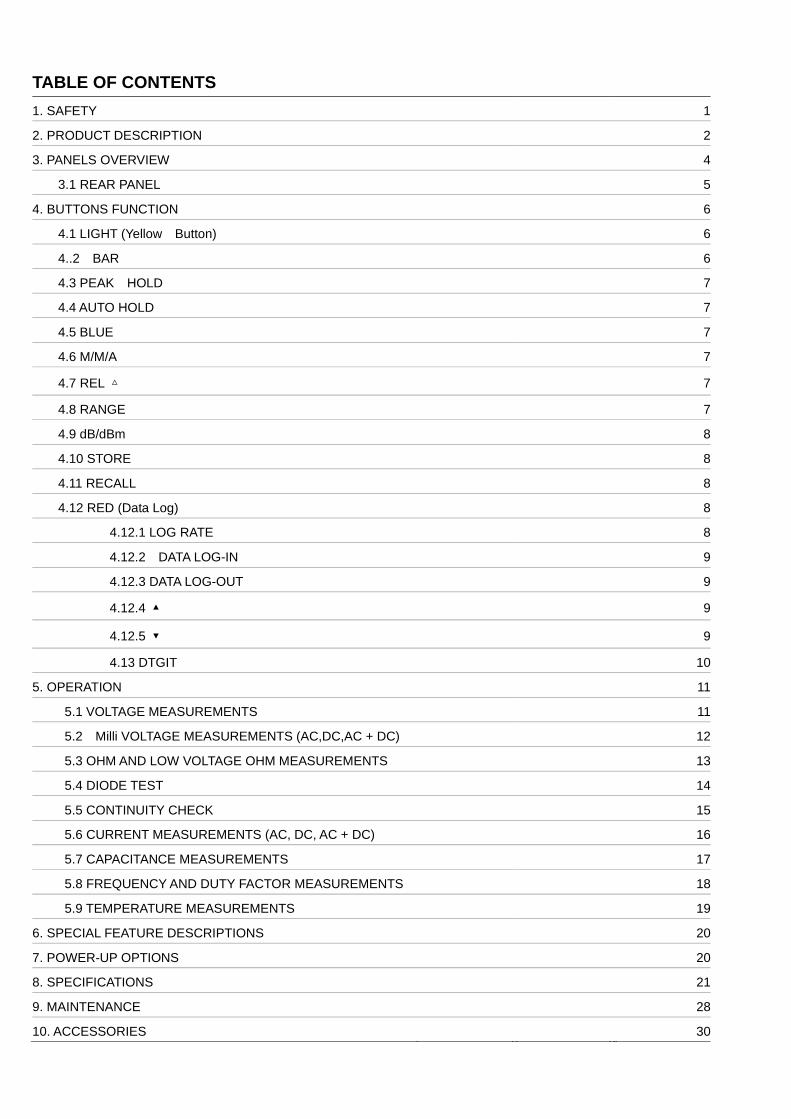
TABLE OF CONTENTS 1. SAFETY 1
2. PRODUCT DESCRIPTION 2
3. PANELS OVERVIEW 4
3.1 REAR PANEL 5
4. BUTTONS FUNCTION 6
4.1 LIGHT (Yellow Button) 6
4..2 BAR 6
4.3 PEAK HOLD 7
4.4 AUTO HOLD 7
4.5 BLUE 7
4.6 M/M/A 7
4.7 REL 7
4.8 RANGE 7
4.9 dB/dBm 8
4.10 STORE 8
4.11 RECALL 8
4.12 RED (Data Log) 8
4.12.1 LOG RATE 8
4.12.2 DATA LOG-IN 9
4.12.3 DATA LOG-OUT 9
4.12.4 9
4.12.5 9
4.13 DTGIT 10
5. OPERATION 11
5.1 VOLTAGE MEASUREMENTS 11
5.2 Milli VOLTAGE MEASUREMENTS (AC,DC,AC + DC) 12
5.3 OHM AND LOW VOLTAGE OHM MEASUREMENTS 13
5.4 DIODE TEST 14
5.5 CONTINUITY CHECK 15
5.6 CURRENT MEASUREMENTS (AC, DC, AC + DC) 16
5.7 CAPACITANCE MEASUREMENTS 17
5.8 FREQUENCY AND DUTY FACTOR MEASUREMENTS 18
5.9 TEMPERATURE MEASUREMENTS 19
6. SPECIAL FEATURE DESCRIPTIONS 20
7. POWER-UP OPTIONS 20
8. SPECIFICATIONS 21
9. MAINTENANCE 28
10. ACCESSORIES 30
1. SAFETY Review the following safety precautions to avoid injury and prevent damage to this product or any products connected to it. To avoid potential hazards, use the product only as specified. # CAUTION. These statements identify conditions or practices that could result in damage to the equipment or other property. # WARNING. These statements identify conditions or practices that could result in personal injury or loss of life. Symbols on the product # Refer to manual 1 Double Insulated " High Voltage Specific precautions Use proper Fuse. To avoid fire hazard, use only the fuse type and rating specified for this product. Do not operate without covers. To avoid personal injury , do not apply any voltage or current to the product without the covers in place. Electric overload. Never apply a voltage to a connector on the product that is outside the range specified for that connector. Avoid electric shock. To avoid injury or loss of life, do not connect or disconnect probes or test leads while they are connected to a voltage source. Do not operate in wet/damp conditions. To avoid electric shock , do not operate this product in wet or damp conditions.
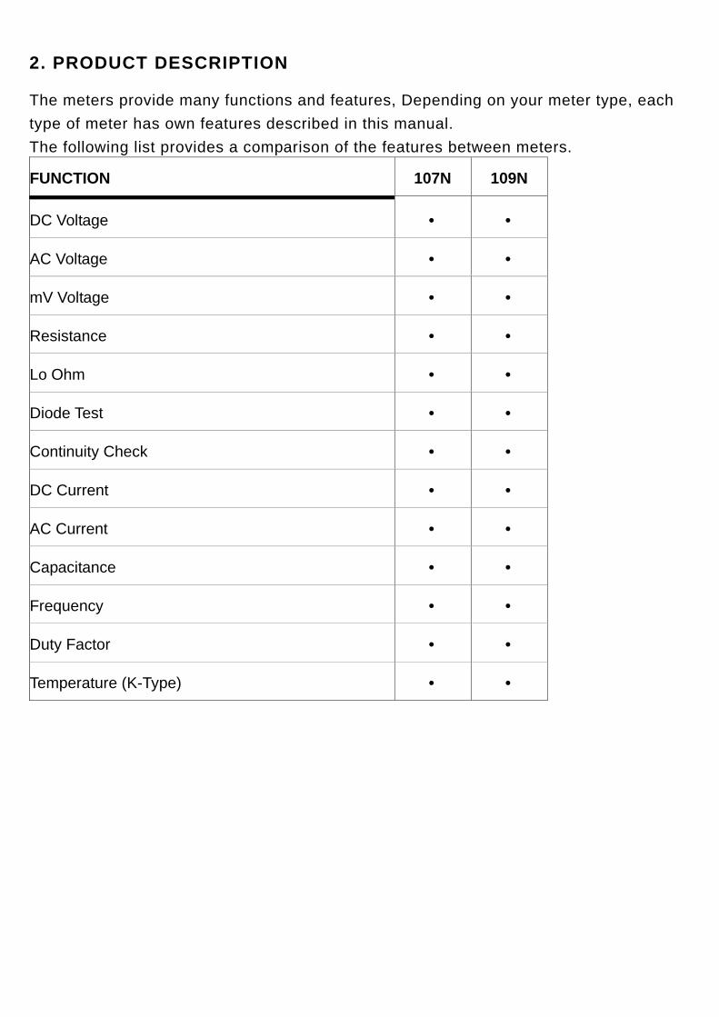
2. PRODUCT DESCRIPTION
The meters provide many functions and features, Depending on your meter type, each type of meter has own features described in this manual. The following list provides a comparison of the features between meters. FUNCTION 107N 109N
DC Voltage • •
AC Voltage • •
mV Voltage • •
Resistance • •
Lo Ohm • •
Diode Test • •
Continuity Check • •
DC Current • •
AC Current • •
Capacitance • •
Frequency • •
Duty Factor • •
Temperature (K-Type) • •
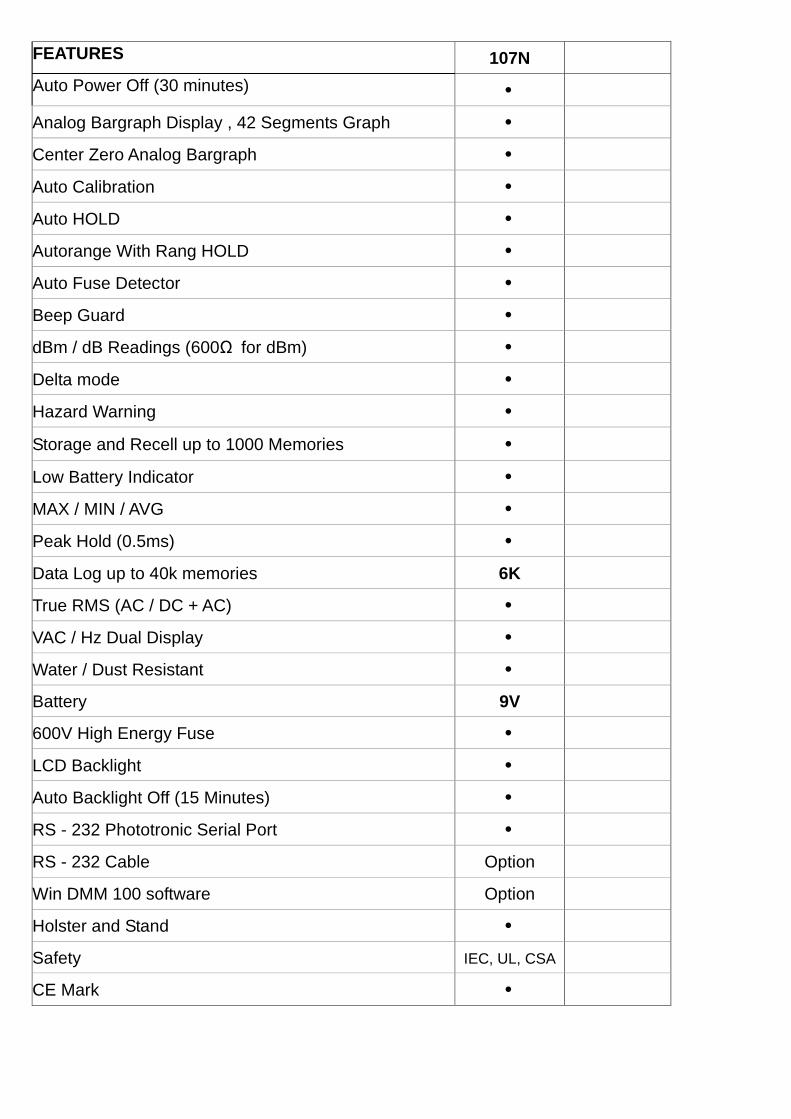
FEATURES 107N Auto Power Off (30 minutes) • Analog Bargraph Display , 42 Segments Graph • Center Zero Analog Bargraph • Auto Calibration • Auto HOLD • Autorange With Rang HOLD • Auto Fuse Detector • Beep Guard • dBm / dB Readings (600Ω for dBm) • Delta mode • Hazard Warning • Storage and Recell up to 1000 Memories • Low Battery Indicator • MAX / MIN / AVG • Peak Hold (0.5ms) • Data Log up to 40k memories 6K True RMS (AC / DC + AC) • VAC / Hz Dual Display • Water / Dust Resistant • Battery 9V 600V High Energy Fuse • LCD Backlight • Auto Backlight Off (15 Minutes) • RS - 232 Phototronic Serial Port • RS - 232 Cable Option Win DMM 100 software Option Holster and Stand • Safety IEC, UL, CSA CE Mark •
3. FRONT PANEL OVERVIEW
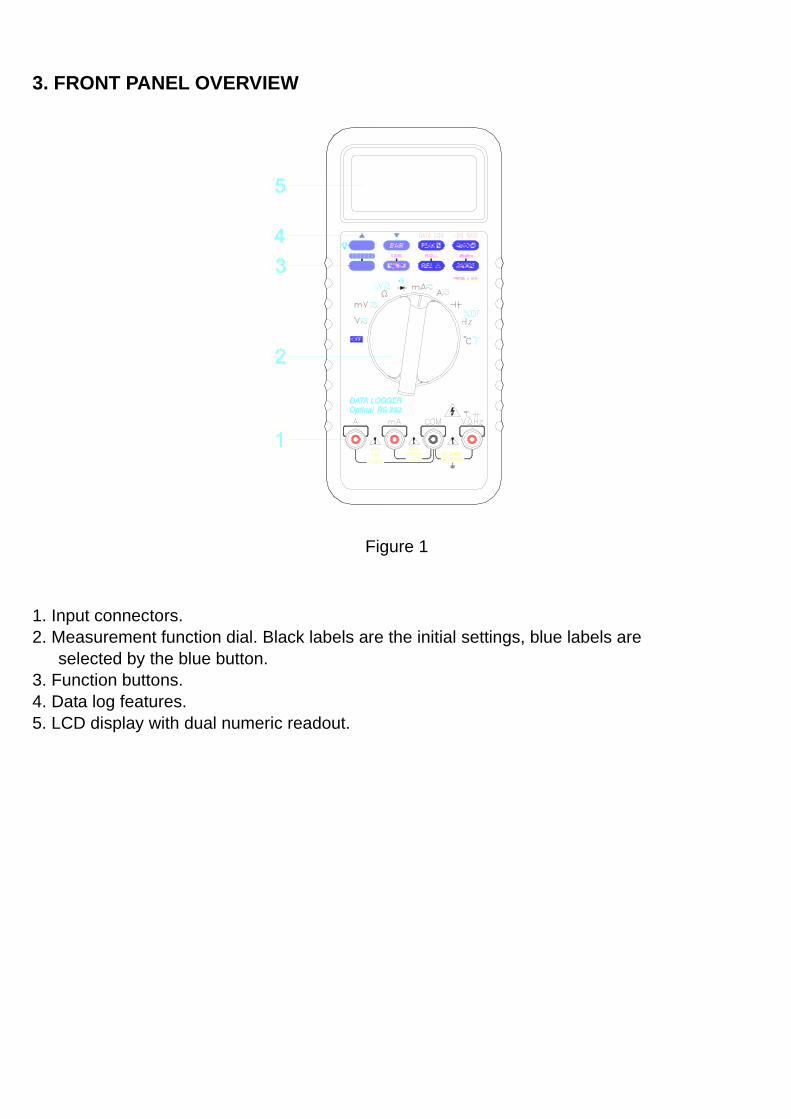
Figure 1
1. Input connectors. 2. Measurement function dial. Black labels are the initial settings, blue labels are selected by the blue button. 3. Function buttons. 4. Data log features. 5. LCD display with dual numeric readout.
3-1 DISPLAY INDICATORS
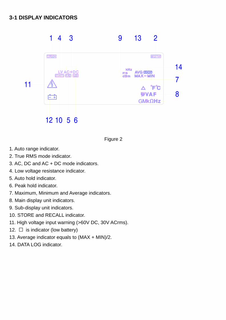
Figure 2
1. Auto range indicator. 2. True RMS mode indicator. 3. AC, DC and AC + DC mode indicators. 4. Low voltage resistance indicator. 5. Auto hold indicator. 6. Peak hold indicator. 7. Maximum, Minimum and Average indicators. 8. Main display unit indicators. 9. Sub-display unit indicators. 10. STORE and RECALL indicator. 11. High voltage input warning (>60V DC, 30V ACrms). 12. is indicator (low battery) 13. Average indicator equals to (MAX + MIN)/2. 14. DATA LOG indicator.
Indicator Unit Indicator Unit
μ micro V Volt
m milli A Ampere
K kilo F Farad
M mega Hz Hertz
delta S Second
% percent Fahrenheit
dB Decibel (1V ref.) Celsius
dBm Decibel(1mW on 600Ω) Ω ohm
G gega n nano
4. BUTTONS FUNCTION
Prediction : Buzzer beeps once for every key-press. Buzzer beeps twice for every invalid key-press.
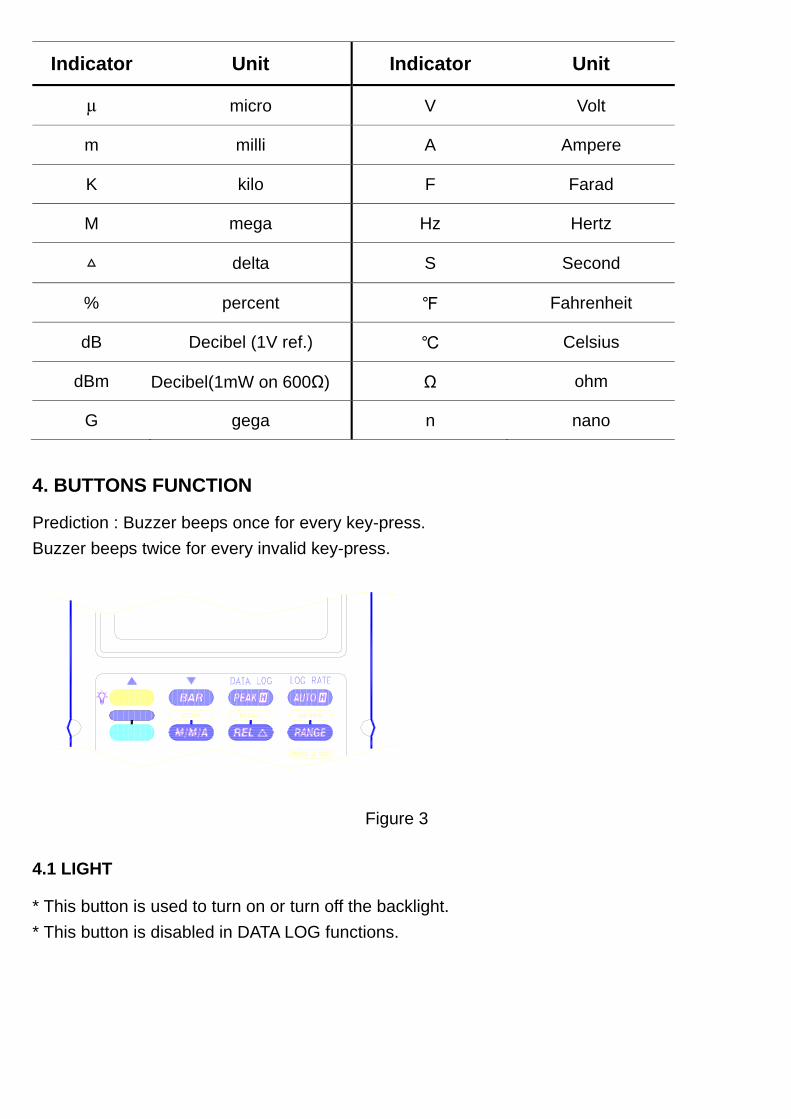
Figure 3
4.1 LIGHT
* This button is used to turn on or turn off the backlight. * This button is disabled in DATA LOG functions.
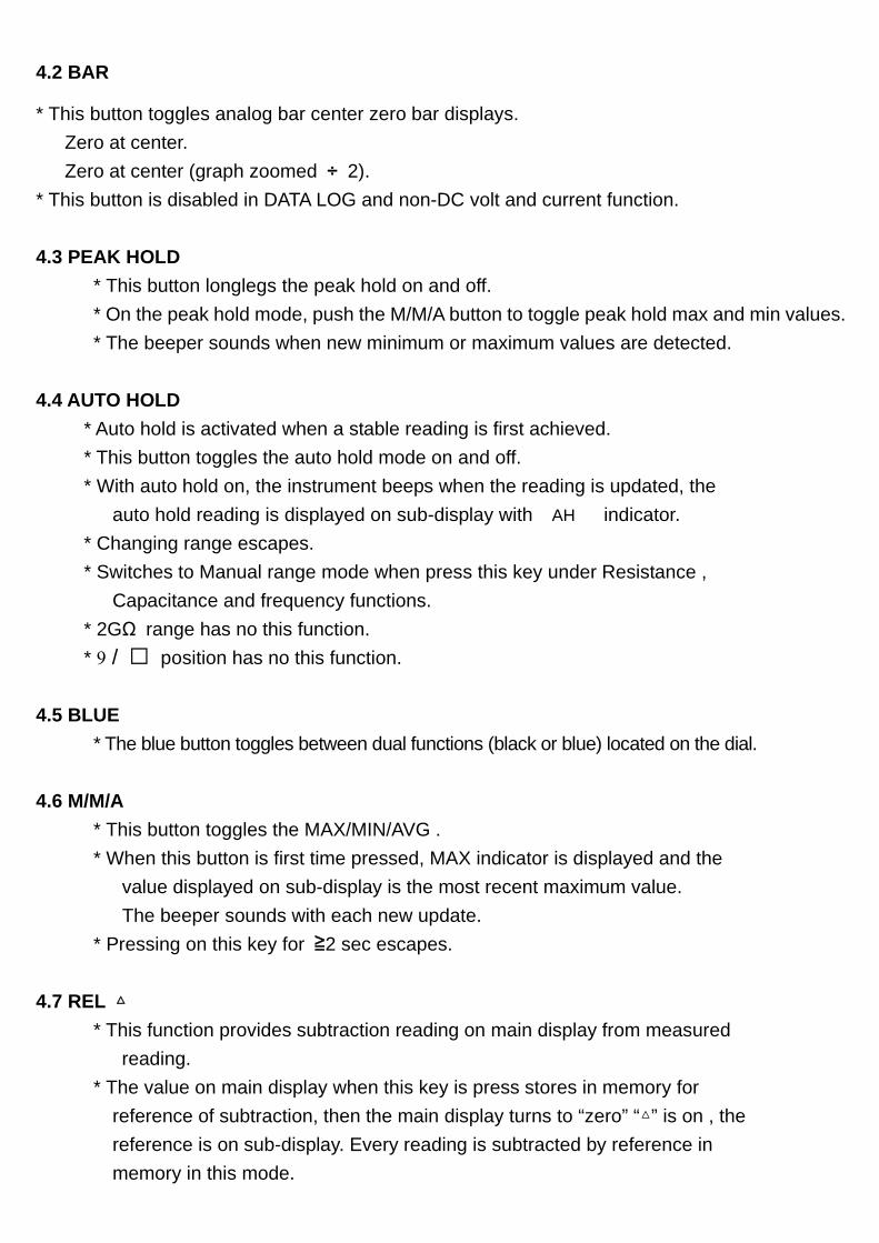
4.2 BAR
* This button toggles analog bar center zero bar displays. Zero at center. Zero at center (graph zoomed ÷ 2). * This button is disabled in DATA LOG and non-DC volt and current function. 4.3 PEAK HOLD * This button longlegs the peak hold on and off. * On the peak hold mode, push the M/M/A button to toggle peak hold max and min values. * The beeper sounds when new minimum or maximum values are detected. 4.4 AUTO HOLD * Auto hold is activated when a stable reading is first achieved. * This button toggles the auto hold mode on and off. * With auto hold on, the instrument beeps when the reading is updated, the auto hold reading is displayed on sub-display with AH indicator. * Changing range escapes. * Switches to Manual range mode when press this key under Resistance , Capacitance and frequency functions. * 2GΩ range has no this function. * 9 / position has no this function. 4.5 BLUE * The blue button toggles between dual functions (black or blue) located on the dial. 4.6 M/M/A * This button toggles the MAX/MIN/AVG . * When this button is first time pressed, MAX indicator is displayed and the value displayed on sub-display is the most recent maximum value. The beeper sounds with each new update. * Pressing on this key for ≧2 sec escapes. 4.7 REL * This function provides subtraction reading on main display from measured reading. * The value on main display when this key is press stores in memory for reference of subtraction, then the main display turns to “zero” “” is on , the reference is on sub-display. Every reading is subtracted by reference in memory in this mode.
* Press again to escape. 4.8 Range * It switches meter auto ranging or manual ranging and range change in manual range mode. * Pressing this key for 2 sec turns manual ranging to auto ranging mode. 4.9 dB/dBm * Pressing RANGE key for ≧ 2 sec enables "dB/dBm" function in AC Volt mode; One press in this mode toggles dB and dBm. * The reading of dB or dBm appears on sub-display, reference resistance for dBm is 600Ω and reference voltage for dB is 1V. * Again 2 sec press on this key in this mode escaps. 4.10 STORE * Pressing M/M/A key for ≧ 2 sec enables "STORE" function, one press in this mode stores reading just measured, in memory offering up to 1000 stores. When store is full, Every press beeps twice. * Again 2 sec press on this key in this mode escaps. * Power-up with PEAK key pressing to clear stores. 4.11 RECALL * Pressing REL key for ≧ 2 enables "RECALL" function. * Again 2 sec press on this key in this mode escaps. * In RECALL mode, use arrow keys (“” , “ “) marked above yellow and BAR keys to scroll and veiw up and down the stored readings; arrow keys perform scroll rate of 10 data/sec when is pressed ≧2 sec and hold. 4.12 RED (Data Log) * Predictions : A. Data quantities : 40K readings form as sequence number on sub-display up to 9999 and each 1/4 scale of bar indicates 10K. (for 109N only) B. RANGE function is only enable in just data log mode. C. Any position (measuring function) change escaps out without storing any data to memory. D. Max. Pause time is 4095 seconds, exceed pause time stores as 4095 seconds. E. Max. Pause and Log Rate setting quantities are 3.6K. F. Auto Power Off function is disabled.
* Pressing BLUE key ≧ 2 sec turns meter into Data log mode, then can be chose desired Data log function. * Again 2 sec press on this key in this mode while not in any Data Log function mode escaps, otherwise, any press on this key is invalid. 4.12.1 LOG RATE * Selectable Log Rate has 0.5", 1", 10", 30", 60", 120", 180", 240" 300”, 360”, 480” and 600”. * One press on AUTO H key (LOG RATE) enables this function, the 1st default is on sub-display, use "" or "" to select Log Rate period for data log-in. * The default (1st) Log Rate is adapted to measuring requirements. * Again press this key once in this mode confirms the Log Rate for log-in and escaps. 4.12.2 DATA LOG-IN * Pressing on PEAK H key ≧ 2 sec enables data log-in function. * Meter starts storing measured reading referring to log rate selected into memory. * One press on this key in this mode interrupts data log-in with “PAUS” on sub-display for log rate re-setting. * While data log-in performing, the “—” sub-display is blinking for storing indication. * When stores data at 40Kth (6Kth for 107N), data log-in stops, the bar is full (for 109 only) , sub-display keeps blinking “—” and showing FULL. 4.12.3 DATA LOG-OUT * One press on PEAK H key (DATA LOG) enables data log-out function when is just in data log mode, sub-display appears sequence number of this logged-in reading has displayed on main display. * The first data displayed when just enabled data log-out is the last reading logged-in. * In this mode, one press on "" or "" key sequentely steps up or down the logged-in data. * Pressing on "" or "" key ≧ 2 sec performs sequentely steps up or down the logged-in data with 10 data/sec display rate and stops at the reading when the key is released. * In this mode, one press M/ M/ A key toggles maximum and minimum values logged-in, pressing on ≧ 2 sec escaps. * In this mode, press RANGE key and then press on "" or "" key toggles the turning points logged-in with “MAX” or “MIN” symbol depending
on the comparison from current reading and next reading. Press Range key again to escape. 4.12.4 : Scrolls up data of function selected. 4.12.5 : Scrolls down data of function selected. 4.13 DIGIT * Pressing on BAR key for ≧ 2 sec enables “DIGIT” function, again 2 sec pressing excapes. * Press under this mode toggles 20000 / 4000 count modes. * Rotate to power OFF then on to reset to 20000 count mode (default). * This key is not available on following items. 4.13.1 200MΩ and 2GΩ ranges of Resistances function. 4.13.2 “9” / “ ” position. 4.13.3 “ ” position. 4.13.4 “Hz” / “%DF” position.
4.13.5 “°C “ / “°F “ position.
5 OPERATION
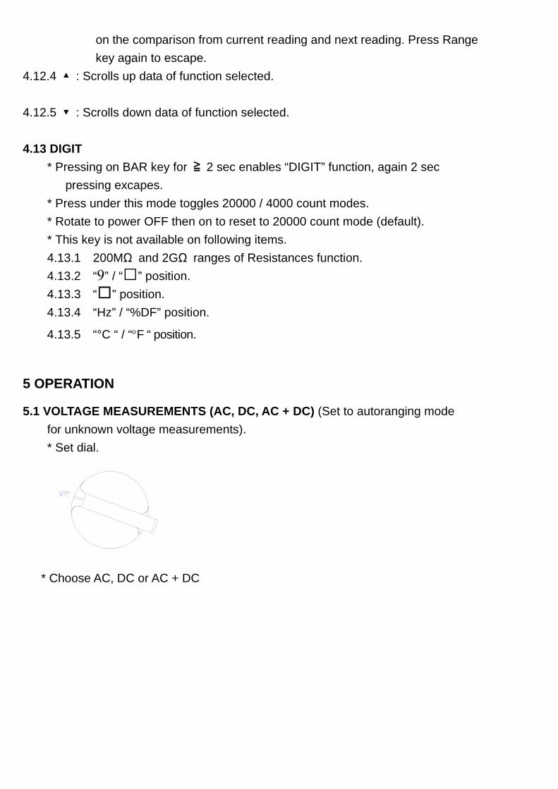
5.1 VOLTAGE MEASUREMENTS (AC, DC, AC + DC) (Set to autoranging mode for unknown voltage measurements). * Set dial.
* Choose AC, DC or AC + DC
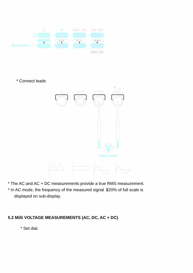
* Connect leads
* The AC and AC + DC measurements provide a true RMS measurement. * In AC mode, the frequency of the measured signal ≧20% of full scale is displayed on sub-display.
5.2 Milli VOLTAGE MEASUREMENTS (AC, DC, AC + DC)
* Set dial.
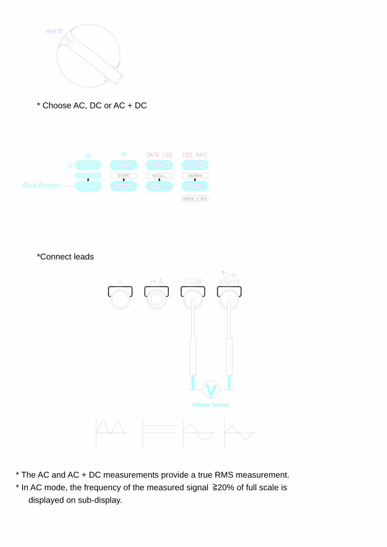
* Choose AC, DC or AC + DC
*Connect leads
* The AC and AC + DC measurements provide a true RMS measurement. * In AC mode, the frequency of the measured signal ≧20% of full scale is displayed on sub-display.
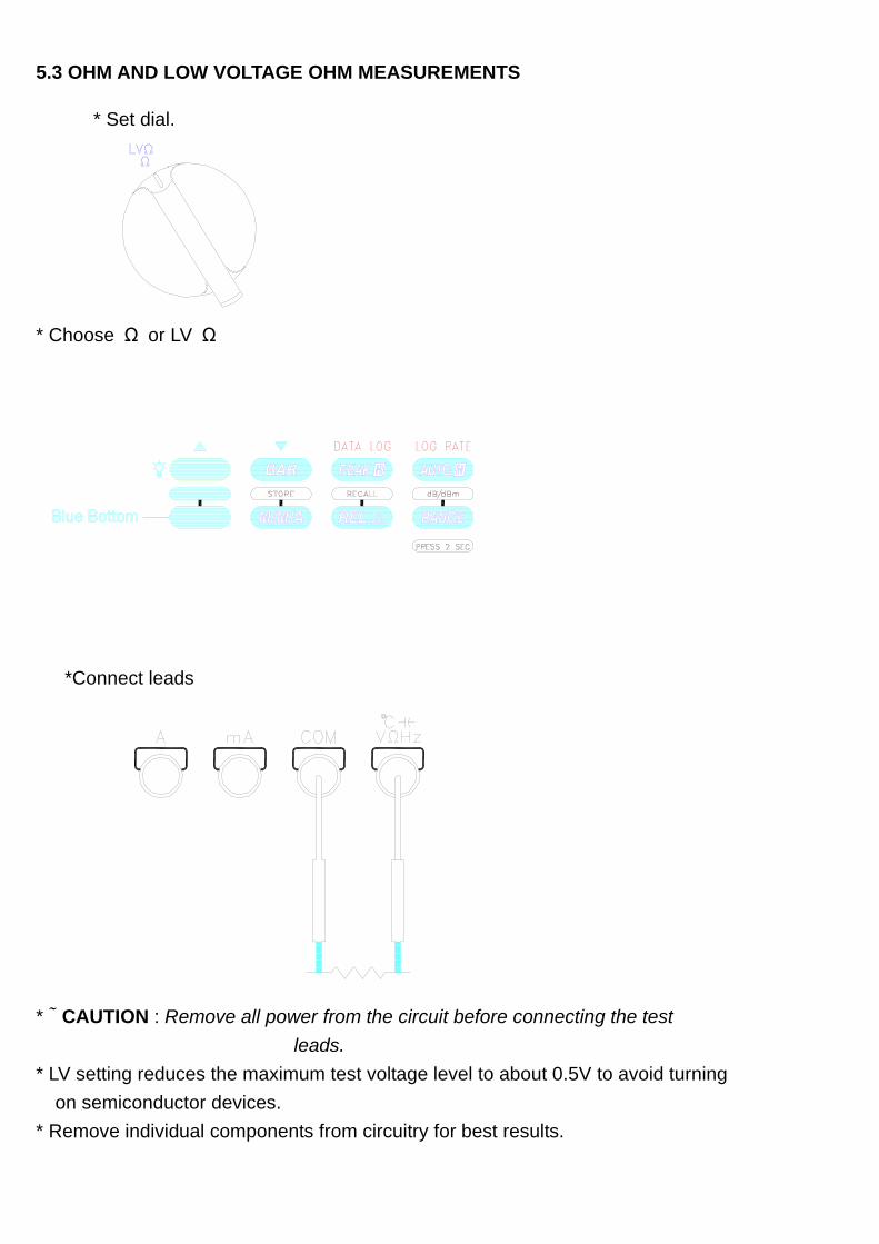
5.3 OHM AND LOW VOLTAGE OHM MEASUREMENTS
* Set dial.
* Choose Ω or LV Ω
*Connect leads
* # CAUTION : Remove all power from the circuit before connecting the test leads. * LV setting reduces the maximum test voltage level to about 0.5V to avoid turning on semiconductor devices. * Remove individual components from circuitry for best results.
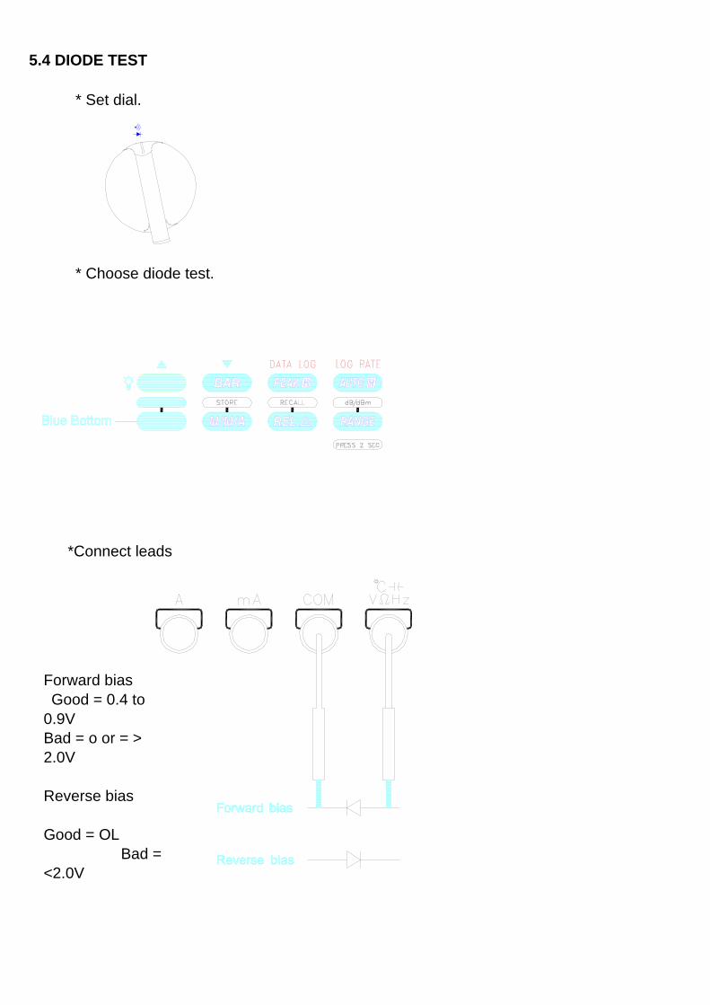
5.4 DIODE TEST
* Set dial.
* Choose diode test.
*Connect leads
Forward bias Good = 0.4 to 0.9V Bad = o or = > 2.0V Reverse bias Good = OL Bad = <2.0V
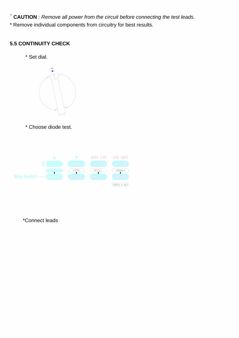
# CAUTION : Remove all power from the circuit before connecting the test leads. * Remove individual components from circuitry for best results. 5.5 CONTINUITY CHECK
* Set dial.
* Choose diode test.
*Connect leads
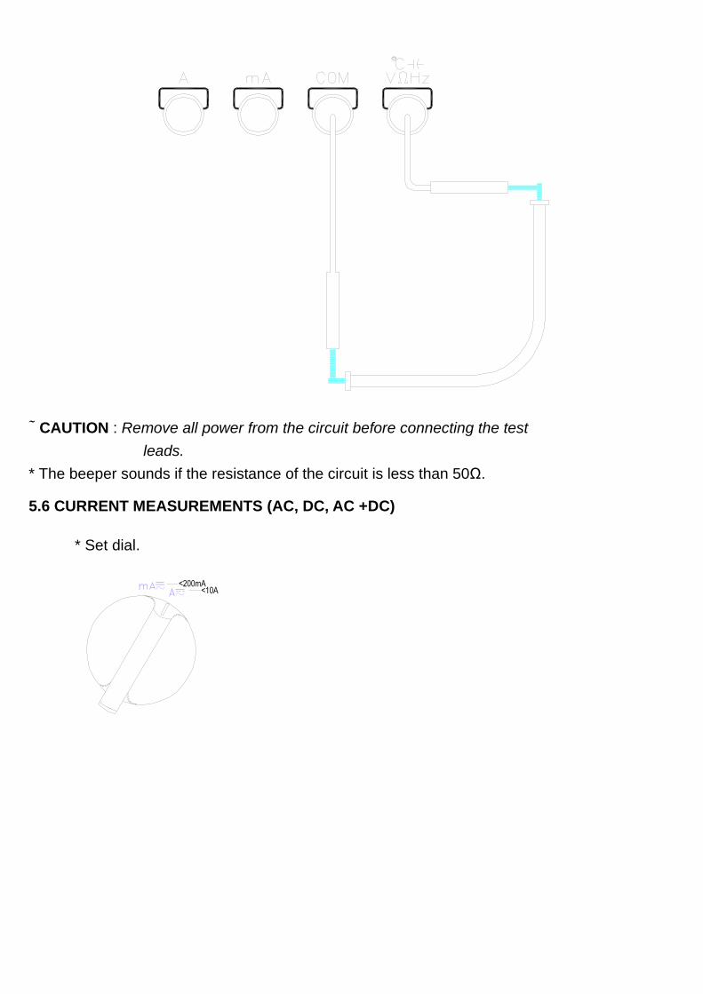
# CAUTION : Remove all power from the circuit before connecting the test leads. * The beeper sounds if the resistance of the circuit is less than 50Ω.
5.6 CURRENT MEASUREMENTS (AC, DC, AC +DC)
* Set dial.
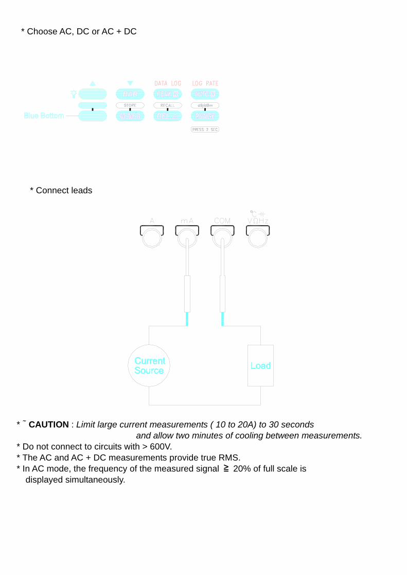
* Choose AC, DC or AC + DC
* Connect leads
* # CAUTION : Limit large current measurements ( 10 to 20A) to 30 seconds and allow two minutes of cooling between measurements. * Do not connect to circuits with > 600V. * The AC and AC + DC measurements provide true RMS. * In AC mode, the frequency of the measured signal ≧ 20% of full scale is displayed simultaneously.
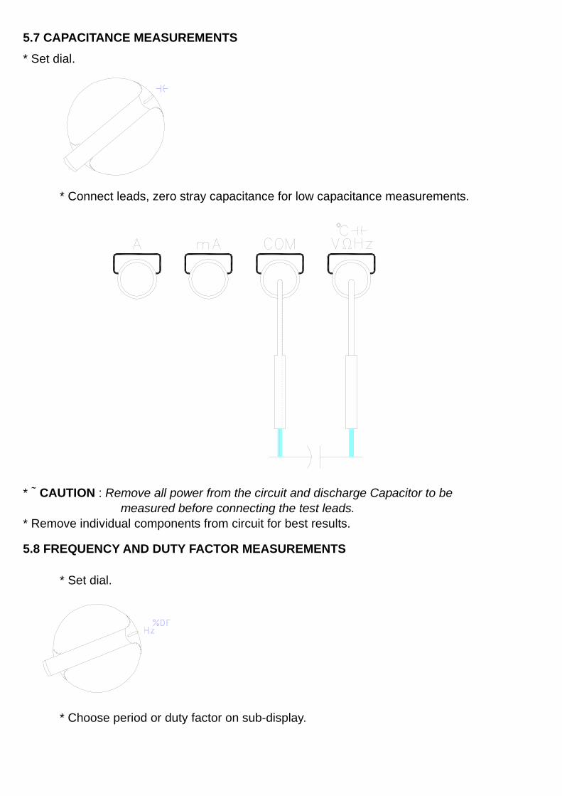
5.7 CAPACITANCE MEASUREMENTS * Set dial.
* Connect leads, zero stray capacitance for low capacitance measurements.
* # CAUTION : Remove all power from the circuit and discharge Capacitor to be measured before connecting the test leads. * Remove individual components from circuit for best results.
5.8 FREQUENCY AND DUTY FACTOR MEASUREMENTS
* Set dial.
* Choose period or duty factor on sub-display.
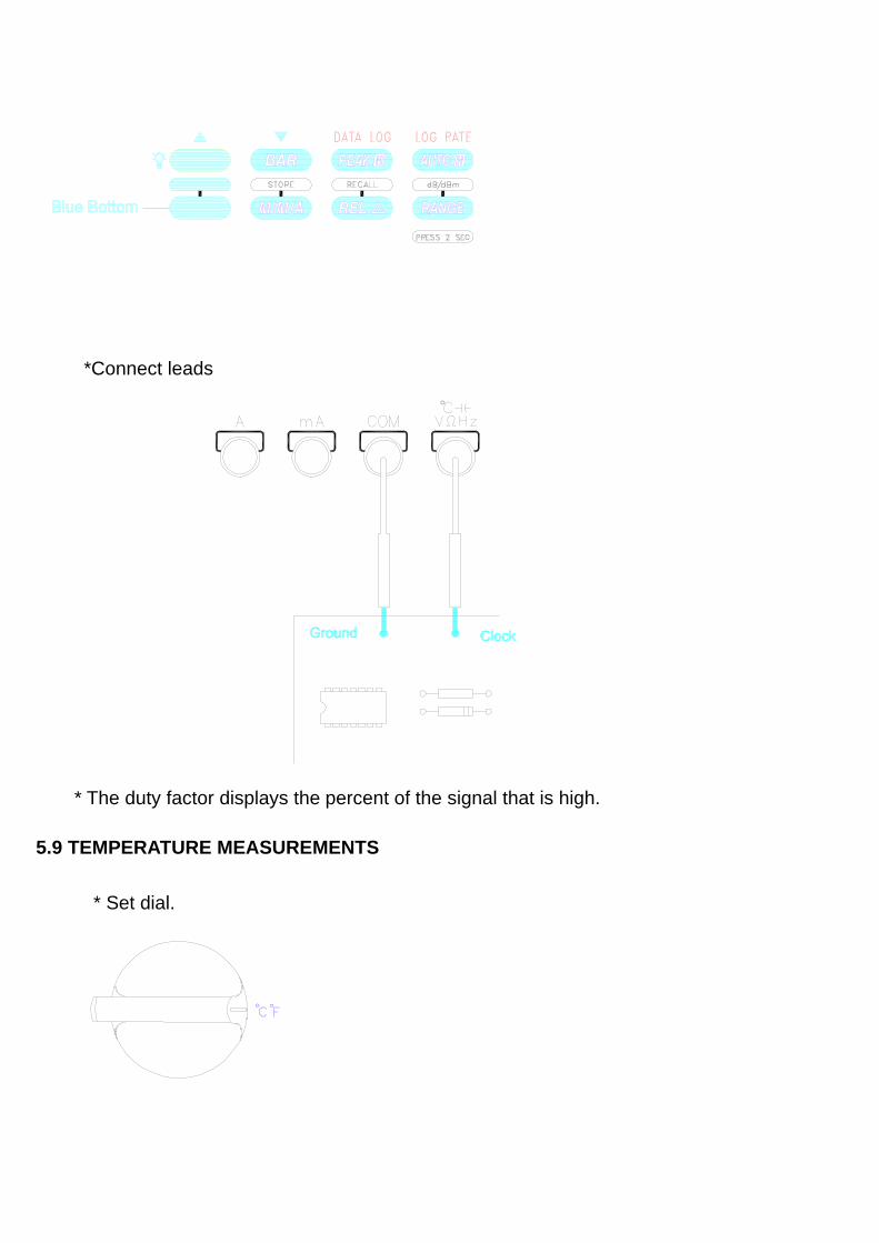
*Connect leads
* The duty factor displays the percent of the signal that is high.
5.9 TEMPERATURE MEASUREMENTS
* Set dial.
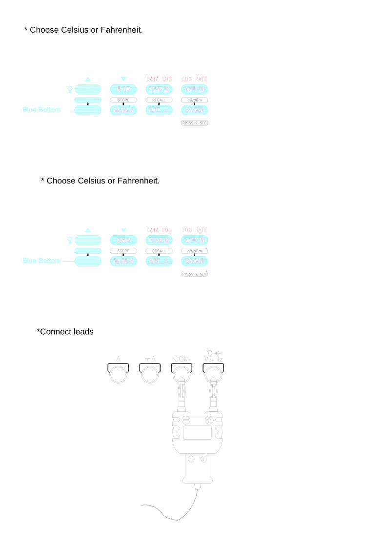
* Choose Celsius or Fahrenheit.
* Choose Celsius or Fahrenheit.
*Connect leads
* This setting requires an optional temperature probe and adapter. Refer to Accessories. * Allow about 5 minutes room temperature balance after settled for best measurement.
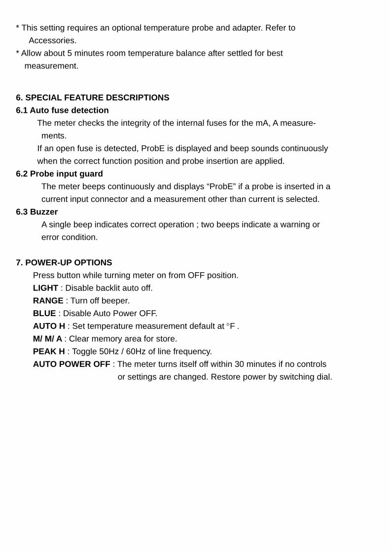
6. SPECIAL FEATURE DESCRIPTIONS 6.1 Auto fuse detection The meter checks the integrity of the internal fuses for the mA, A measure- ments. If an open fuse is detected, ProbE is displayed and beep sounds continuously when the correct function position and probe insertion are applied. 6.2 Probe input guard The meter beeps continuously and displays “ProbE” if a probe is inserted in a current input connector and a measurement other than current is selected. 6.3 Buzzer A single beep indicates correct operation ; two beeps indicate a warning or error condition. 7. POWER-UP OPTIONS Press button while turning meter on from OFF position. LIGHT : Disable backlit auto off. RANGE : Turn off beeper. BLUE : Disable Auto Power OFF. AUTO H : Set temperature measurement default at °F . M/ M/ A : Clear memory area for store. PEAK H : Toggle 50Hz / 60Hz of line frequency. AUTO POWER OFF : The meter turns itself off within 30 minutes if no controls or settings are changed. Restore power by switching dial.
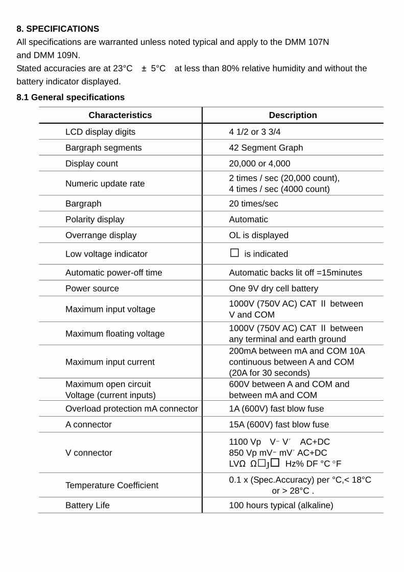
8. SPECIFICATIONS All specifications are warranted unless noted typical and apply to the DMM 107N and DMM 109N. Stated accuracies are at 23°C ± 5°C at less than 80% relative humidity and without the battery indicator displayed.
8.1 General specifications Characteristics Description
LCD display digits 4 1/2 or 3 3/4 Bargraph segments 42 Segment Graph Display count 20,000 or 4,000
Numeric update rate 2 times / sec (20,000 count), 4 times / sec (4000 count)
Bargraph 20 times/sec Polarity display Automatic Overrange display OL is displayed
Low voltage indicator is indicated
Automatic power-off time Automatic backs lit off =15minutes Power source One 9V dry cell battery
Maximum input voltage 1000V (750V AC) CAT Ⅱ between V and COM
Maximum floating voltage 1000V (750V AC) CAT Ⅱ between any terminal and earth ground
Maximum input current 200mA between mA and COM 10A continuous between A and COM (20A for 30 seconds)
Maximum open circuit Voltage (current inputs)
600V between A and COM and between mA and COM
Overload protection mA connector 1A (600V) fast blow fuse A connector 15A (600V) fast blow fuse
V connector 1100 Vp V% V' AC+DC 850 Vp mV% mV' AC+DC LVΩ Ω : Hz% DF °C °F
Temperature Coefficient 0.1 x (Spec.Accuracy) per °C,< 18°C or > 28°C .
Battery Life 100 hours typical (alkaline)
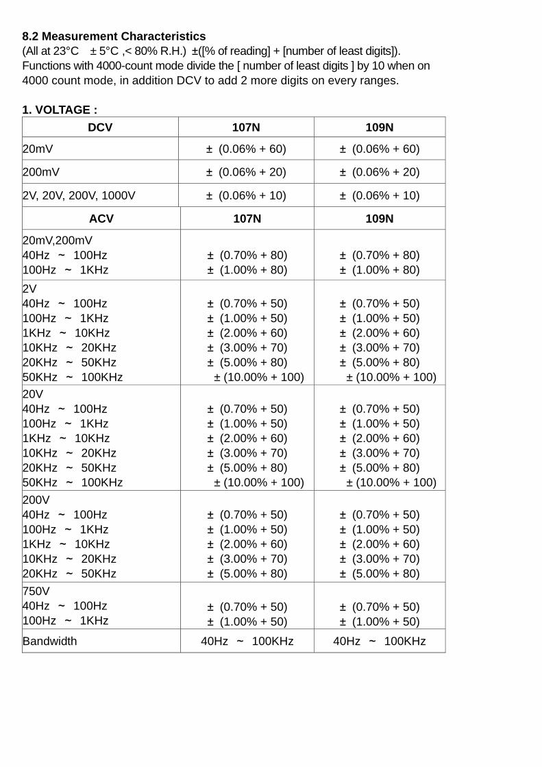
8.2 Measurement Characteristics (All at 23°C ± 5°C ,< 80% R.H.) ±([% of reading] + [number of least digits]). Functions with 4000-count mode divide the [ number of least digits ] by 10 when on 4000 count mode, in addition DCV to add 2 more digits on every ranges. 1. VOLTAGE :
DCV 107N 109N 20mV ± (0.06% + 60) ± (0.06% + 60) 200mV ± (0.06% + 20) ± (0.06% + 20) 2V, 20V, 200V, 1000V ± (0.06% + 10) ± (0.06% + 10)
ACV 107N 109N 20mV,200mV 40Hz ~ 100Hz 100Hz ~ 1KHz
± (0.70% + 80) ± (1.00% + 80)
± (0.70% + 80) ± (1.00% + 80)
2V 40Hz ~ 100Hz 100Hz ~ 1KHz 1KHz ~ 10KHz 10KHz ~ 20KHz 20KHz ~ 50KHz 50KHz ~ 100KHz
± (0.70% + 50) ± (1.00% + 50) ± (2.00% + 60) ± (3.00% + 70) ± (5.00% + 80)
± (10.00% + 100)
± (0.70% + 50) ± (1.00% + 50) ± (2.00% + 60) ± (3.00% + 70) ± (5.00% + 80)
± (10.00% + 100) 20V 40Hz ~ 100Hz 100Hz ~ 1KHz 1KHz ~ 10KHz 10KHz ~ 20KHz 20KHz ~ 50KHz 50KHz ~ 100KHz
± (0.70% + 50) ± (1.00% + 50) ± (2.00% + 60) ± (3.00% + 70) ± (5.00% + 80)
± (10.00% + 100)
± (0.70% + 50) ± (1.00% + 50) ± (2.00% + 60) ± (3.00% + 70) ± (5.00% + 80)
± (10.00% + 100) 200V 40Hz ~ 100Hz 100Hz ~ 1KHz 1KHz ~ 10KHz 10KHz ~ 20KHz 20KHz ~ 50KHz
± (0.70% + 50) ± (1.00% + 50) ± (2.00% + 60) ± (3.00% + 70) ± (5.00% + 80)
± (0.70% + 50) ± (1.00% + 50) ± (2.00% + 60) ± (3.00% + 70) ± (5.00% + 80)
750V 40Hz ~ 100Hz 100Hz ~ 1KHz
± (0.70% + 50) ± (1.00% + 50)
± (0.70% + 50) ± (1.00% + 50)
Bandwidth 40Hz ~ 100KHz 40Hz ~ 100KHz
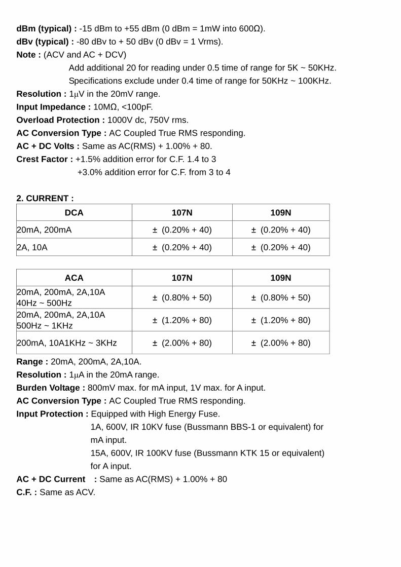
dBm (typical) : -15 dBm to +55 dBm (0 dBm = 1mW into 600Ω). dBv (typical) : -80 dBv to + 50 dBv (0 dBv = 1 Vrms). Note : (ACV and AC + DCV) Add additional 20 for reading under 0.5 time of range for 5K ~ 50KHz. Specifications exclude under 0.4 time of range for 50KHz ~ 100KHz. Resolution : 1μV in the 20mV range. Input Impedance : 10MΩ, <100pF. Overload Protection : 1000V dc, 750V rms. AC Conversion Type : AC Coupled True RMS responding. AC + DC Volts : Same as AC(RMS) + 1.00% + 80. Crest Factor : +1.5% addition error for C.F. 1.4 to 3 +3.0% addition error for C.F. from 3 to 4 2. CURRENT :
DCA 107N 109N 20mA, 200mA ± (0.20% + 40) ± (0.20% + 40) 2A, 10A ± (0.20% + 40) ± (0.20% + 40)
ACA 107N 109N 20mA, 200mA, 2A,10A 40Hz ~ 500Hz ± (0.80% + 50) ± (0.80% + 50) 20mA, 200mA, 2A,10A 500Hz ~ 1KHz ± (1.20% + 80) ± (1.20% + 80)
200mA, 10A1KHz ~ 3KHz ± (2.00% + 80) ± (2.00% + 80)
Range : 20mA, 200mA, 2A,10A. Resolution : 1μA in the 20mA range. Burden Voltage : 800mV max. for mA input, 1V max. for A input. AC Conversion Type : AC Coupled True RMS responding. Input Protection : Equipped with High Energy Fuse. 1A, 600V, IR 10KV fuse (Bussmann BBS-1 or equivalent) for mA input. 15A, 600V, IR 100KV fuse (Bussmann KTK 15 or equivalent) for A input. AC + DC Current : Same as AC(RMS) + 1.00% + 80 C.F. : Same as ACV.
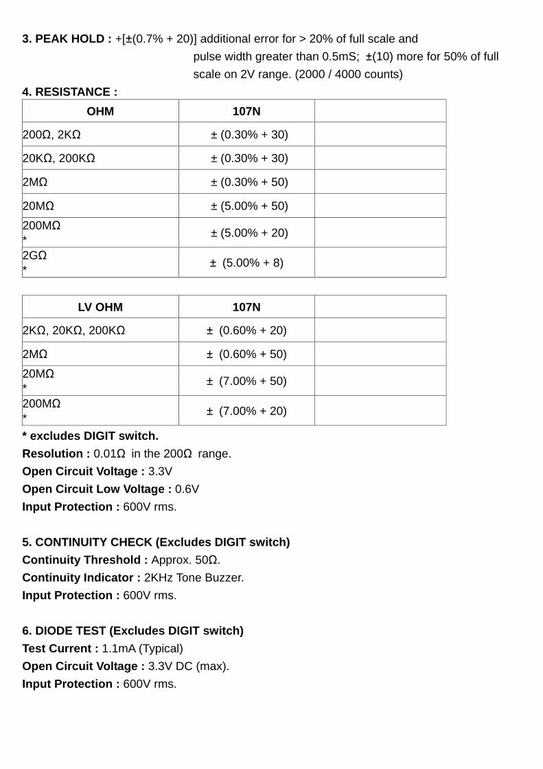
3. PEAK HOLD : +[±(0.7% + 20)] additional error for > 20% of full scale and pulse width greater than 0.5mS; ±(10) more for 50% of full scale on 2V range. (2000 / 4000 counts) 4. RESISTANCE :
OHM 107N 200Ω, 2KΩ ± (0.30% + 30) 20KΩ, 200KΩ ± (0.30% + 30) 2MΩ ± (0.30% + 50) 20MΩ ± (5.00% + 50) 200MΩ * ± (5.00% + 20) 2GΩ * ± (5.00% + 8)
LV OHM 107N
2KΩ, 20KΩ, 200KΩ ± (0.60% + 20) 2MΩ ± (0.60% + 50) 20MΩ * ± (7.00% + 50) 200MΩ * ± (7.00% + 20)
* excludes DIGIT switch. Resolution : 0.01Ω in the 200Ω range. Open Circuit Voltage : 3.3V Open Circuit Low Voltage : 0.6V Input Protection : 600V rms. 5. CONTINUITY CHECK (Excludes DIGIT switch) Continuity Threshold : Approx. 50Ω. Continuity Indicator : 2KHz Tone Buzzer. Input Protection : 600V rms. 6. DIODE TEST (Excludes DIGIT switch) Test Current : 1.1mA (Typical) Open Circuit Voltage : 3.3V DC (max). Input Protection : 600V rms.
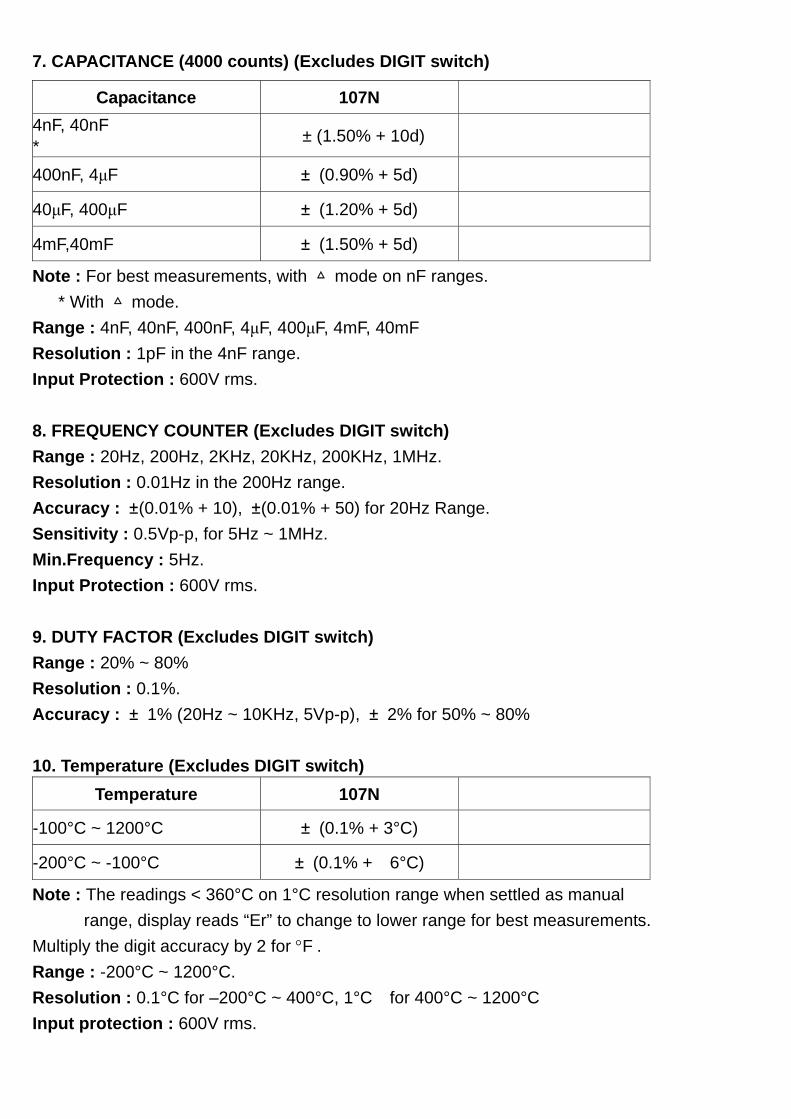
7. CAPACITANCE (4000 counts) (Excludes DIGIT switch)
Capacitance 107N 4nF, 40nF * ± (1.50% + 10d)
400nF, 4μF ± (0.90% + 5d) 40μF, 400μF ± (1.20% + 5d) 4mF,40mF ± (1.50% + 5d) Note : For best measurements, with mode on nF ranges. * With mode. Range : 4nF, 40nF, 400nF, 4μF, 400μF, 4mF, 40mF Resolution : 1pF in the 4nF range. Input Protection : 600V rms. 8. FREQUENCY COUNTER (Excludes DIGIT switch) Range : 20Hz, 200Hz, 2KHz, 20KHz, 200KHz, 1MHz. Resolution : 0.01Hz in the 200Hz range. Accuracy : ±(0.01% + 10), ±(0.01% + 50) for 20Hz Range. Sensitivity : 0.5Vp-p, for 5Hz ~ 1MHz. Min.Frequency : 5Hz. Input Protection : 600V rms. 9. DUTY FACTOR (Excludes DIGIT switch) Range : 20% ~ 80% Resolution : 0.1%. Accuracy : ± 1% (20Hz ~ 10KHz, 5Vp-p), ± 2% for 50% ~ 80% 10. Temperature (Excludes DIGIT switch)
Temperature 107N -100°C ~ 1200°C ± (0.1% + 3°C) -200°C ~ -100°C ± (0.1% + 6°C) Note : The readings < 360°C on 1°C resolution range when settled as manual range, display reads “Er” to change to lower range for best measurements. Multiply the digit accuracy by 2 for °F . Range : -200°C ~ 1200°C. Resolution : 0.1°C for –200°C ~ 400°C, 1°C for 400°C ~ 1200°C Input protection : 600V rms.
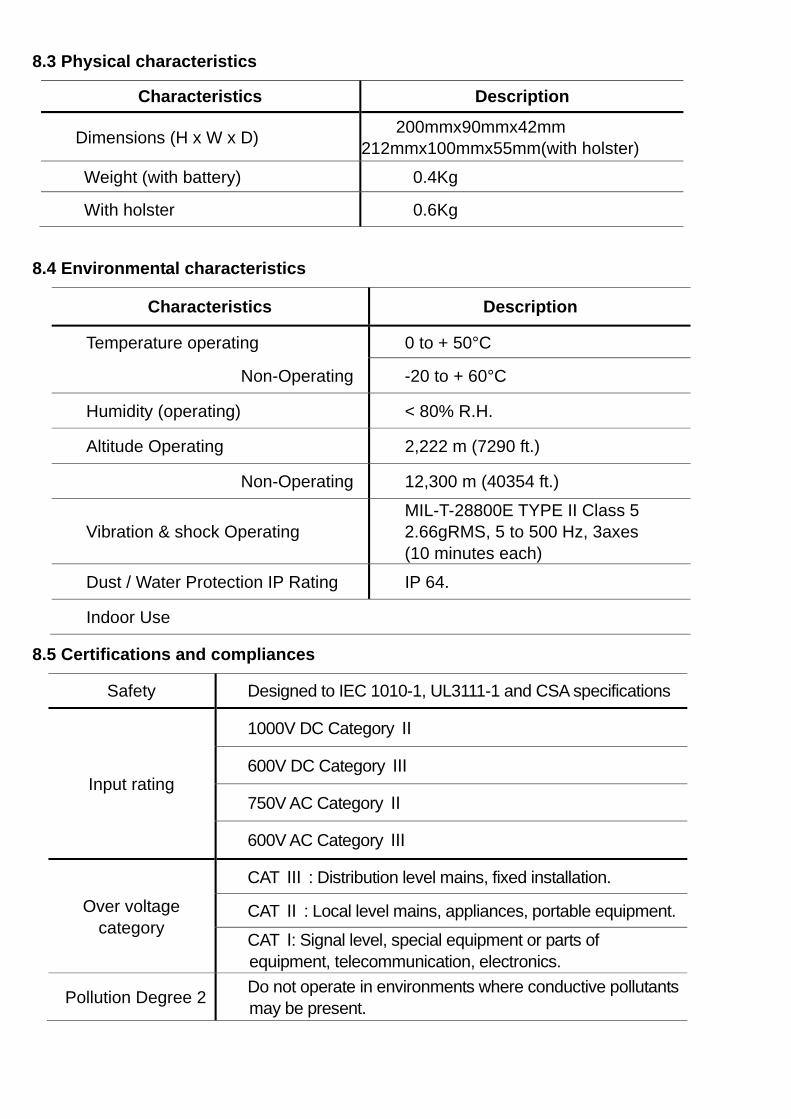
8.3 Physical characteristics
Characteristics Description
Dimensions (H x W x D) 200mmx90mmx42mm 212mmx100mmx55mm(with holster)
Weight (with battery) 0.4Kg With holster 0.6Kg
8.4 Environmental characteristics
Characteristics Description
Temperature operating 0 to + 50°C Non-Operating -20 to + 60°C Humidity (operating) < 80% R.H. Altitude Operating 2,222 m (7290 ft.) Non-Operating 12,300 m (40354 ft.)
Vibration & shock Operating MIL-T-28800E TYPE II Class 5
2.66gRMS, 5 to 500 Hz, 3axes (10 minutes each)
Dust / Water Protection IP Rating IP 64. Indoor Use
8.5 Certifications and compliances
Safety Designed to IEC 1010-1, UL3111-1 and CSA specifications
Input rating
1000V DC Category Ⅱ
600V DC Category Ⅲ
750V AC Category Ⅱ
600V AC Category Ⅲ
Over voltage category
CAT Ⅲ : Distribution level mains, fixed installation. CAT Ⅱ : Local level mains, appliances, portable equipment. CAT Ⅰ: Signal level, special equipment or parts of
equipment, telecommunication, electronics.
Pollution Degree 2 Do not operate in environments where conductive pollutants may be present.
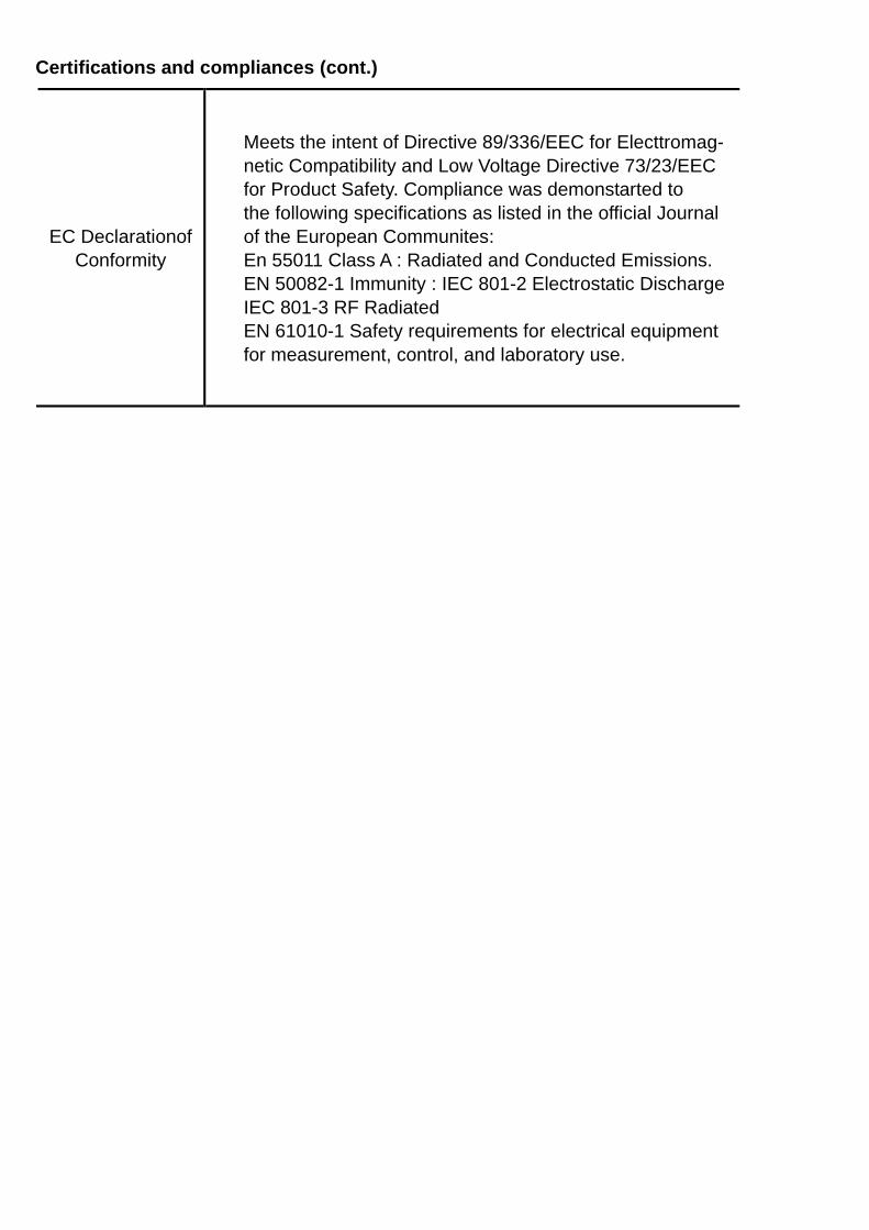
Certifications and compliances (cont.)
EC Declarationof Conformity
Meets the intent of Directive 89/336/EEC for Electtromag- netic Compatibility and Low Voltage Directive 73/23/EEC for Product Safety. Compliance was demonstarted to the following specifications as listed in the official Journal of the European Communites: En 55011 Class A : Radiated and Conducted Emissions. EN 50082-1 Immunity : IEC 801-2 Electrostatic Discharge IEC 801-3 RF Radiated EN 61010-1 Safety requirements for electrical equipment for measurement, control, and laboratory use.
9. MAINTENANCE
Protect the meter from adverse weather conditions. The meter is not waterproof. Do not expose the LCD display to direct sunlight for long period of time. # CAUTIONS. To avoid damage to the meter, do not expose it to sprays, liquids, or solvents. Clean the exterior of the meter by removing dust with a lint-free cloth. Use care to Avoid scratching the clear plastic display filter. For further cleaning, use a soft cloth or paper towel dampened with water. You can use a 75% isopropyl alcohol solution for more efficient cleaning. # CAUTION. To avoid damage to the surface of the meter, do not use abrasive or chemical cleaning agents. BATTERY REPLACEMENT (refer to Figure 4) 1. Disconnect the test leads from any circuit under test and turn off meter. 2. Remove the test leads from meter. 3. Loosen the plastic screws on the battery cover. 4. Remove battery cover from case bottom. 5. Install a new battery after removing the original one. 6. Assemble battery cover onto bottom case with screw driver. FUSE REPLACEMENT (refer to Figure 5) 1. Follow step 1 to step 4 described in Battery Replacement. 2. Remove the battery from meter. 3. Remove 3 screws installed the top case and bottom case of meter. 4. Separate the top case and PCB of meter. 5. Replace a new fuse(FUSE 1 or FUSE 2). 6. Assemble the top case and PCB of meter. 7. Assemble the top case, PCB, and bottom case of meter. 8. Install the battery removed and assemble the battery cover.
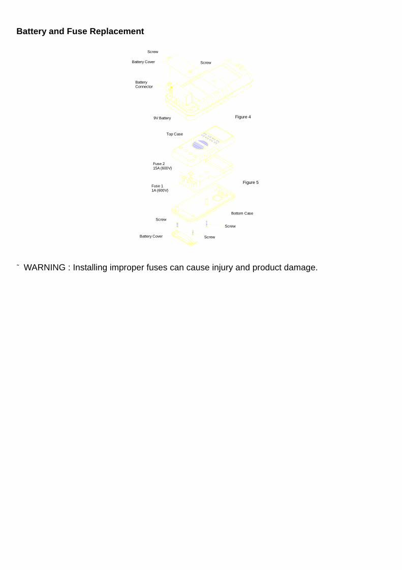
Battery and Fuse Replacement
Screw
Screw
Battery Cover
Battery Connector
9V Battery
Figure 4
Screw
Bottom Case
Figure 5Fuse1
1A(600v)
Battery Cover
Screw
Screw
Fuse2 15A(600v)
Top Case
Figure 4
Figure 5
Screw
Screw Battery Cover
Battery Connector
9V Battery
Top Case
Bottom Case Screw
Screw
Screw Battery Cover
Fuse 1 1A (600V)
Fuse 2 15A (600V)
# WARNING : Installing improper fuses can cause injury and product damage.
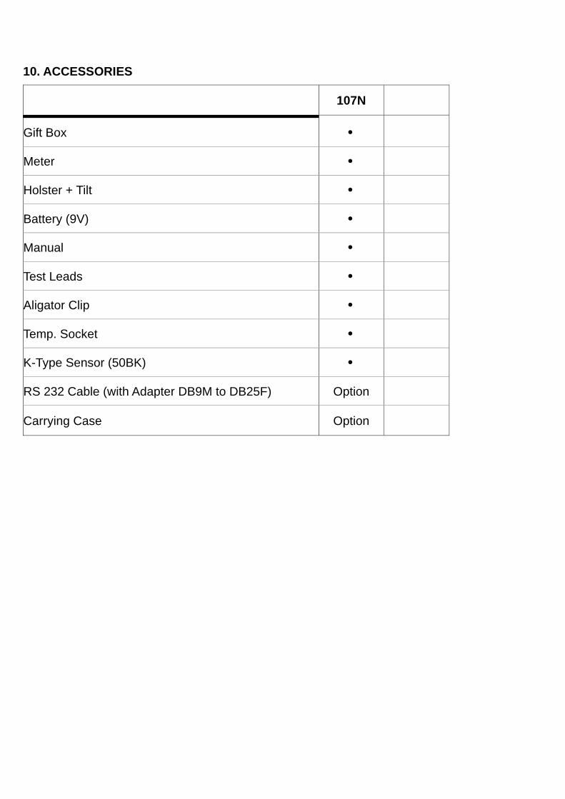
10. ACCESSORIES
107N
Gift Box •
Meter •
Holster + Tilt •
Battery (9V) •
Manual •
Test Leads •
Aligator Clip •
Temp. Socket •
K-Type Sensor (50BK) •
RS 232 Cable (with Adapter DB9M to DB25F) Option
Carrying Case Option