Embed Size (px)
Citation preview
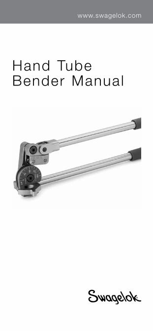
Hand Tube Bender Manual
www.swagelok.com

2
3
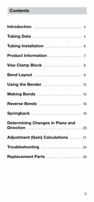
Contents
Introduction . . . . . . . . . . . . . . . . . . . . . . . . . . . 4
Tubing Data . . . . . . . . . . . . . . . . . . . . . . . . . . . . 4
Tubing Installation . . . . . . . . . . . . . . . . . . . . . 6
Product Information . . . . . . . . . . . . . . . . . . . 7
Vise Clamp Block . . . . . . . . . . . . . . . . . . . . . . 8
Bend Layout . . . . . . . . . . . . . . . . . . . . . . . . . . . 9
Using the Bender . . . . . . . . . . . . . . . . . . . . . . 12
Making Bends . . . . . . . . . . . . . . . . . . . . . . . . . 15
Reverse Bends . . . . . . . . . . . . . . . . . . . . . . . . 18
Springback . . . . . . . . . . . . . . . . . . . . . . . . . . . . 19
Determining Changes in Plane and Direction . . . . . . . . . . . . . . . . . . . . . . . . . . . . . . . 20
Adjustment (Gain) Calculations . . . . . . . 21
Troubleshooting . . . . . . . . . . . . . . . . . . . . . . . 24
Replacement Parts . . . . . . . . . . . . . . . . . . . . 26
4
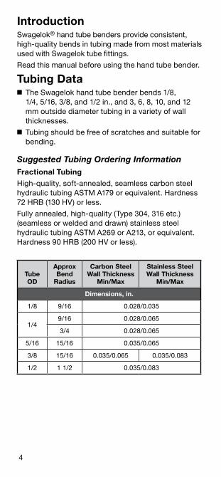
IntroductionSwagelok® hand tube benders provide consistent, high‑quality bends in tubing made from most materials used with Swagelok tube fittings .
Read this manual before using the hand tube bender .
Tubing Data■ The Swagelok hand tube bender bends 1/8,
1/4, 5/16, 3/8, and 1/2 in ., and 3, 6, 8, 10, and 12 mm outside diameter tubing in a variety of wall thicknesses .
■ Tubing should be free of scratches and suitable for bending .
Suggested Tubing Ordering InformationFractional Tubing
High‑quality, soft‑annealed, seamless carbon steel hydraulic tubing ASTM A179 or equivalent . Hardness 72 HRB (130 HV) or less .
Fully annealed, high‑quality (Type 304, 316 etc .) (seamless or welded and drawn) stainless steel hydraulic tubing ASTM A269 or A213, or equivalent . Hardness 90 HRB (200 HV or less) .
Tube OD
Approx Bend
Radius
Carbon Steel Wall Thickness
Min/Max
Stainless Steel Wall Thickness
Min/Max
Dimensions, in.
1/8 9/16 0 .028/0 .035
1/49/16 0 .028/0 .065
3/4 0 .028/0 .065
5/16 15/16 0 .035/0 .065
3/8 15/16 0 .035/0 .065 0 .035/0 .083
1/2 1 1/2 0 .035/0 .083
5
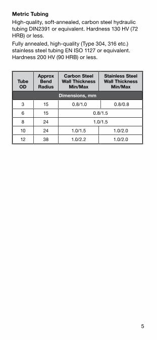
Metric Tubing
High‑quality, soft‑annealed, carbon steel hydraulic tubing DIN2391 or equivalent . Hardness 130 HV (72 HRB) or less .
Fully annealed, high‑quality (Type 304, 316 etc .) stainless steel tubing EN ISO 1127 or equivalent . Hardness 200 HV (90 HRB) or less .
Tube OD
Approx Bend
Radius
Carbon Steel Wall Thickness
Min/Max
Stainless Steel Wall Thickness
Min/Max
Dimensions, mm
3 15 0 .8/1 .0 0 .8/0 .8
6 15 0 .8/1 .5
8 24 1 .0/1 .5
10 24 1 .0/1 .5 1 .0/2 .0
12 38 1 .0/2 .2 1 .0/2 .0
6
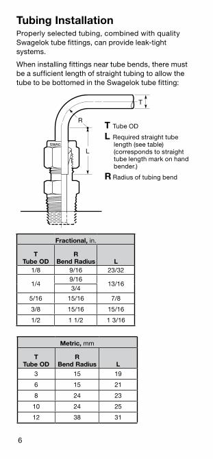
Tubing InstallationProperly selected tubing, combined with quality Swagelok tube fittings, can provide leak‑tight systems .
When installing fittings near tube bends, there must be a sufficient length of straight tubing to allow the tube to be bottomed in the Swagelok tube fitting:
L
T
R
Metric, mm
TTube OD
RBend Radius L
3 15 19
6 15 21
8 24 23
10 24 25
12 38 31
Fractional, in .
TTube OD
RBend Radius L
1/8 9/16 23/32
1/49/16
13/163/4
5/16 15/16 7/8
3/8 15/16 15/16
1/2 1 1/2 1 3/16
T Tube OD
L Required straight tube length (see table) (corresponds to straight tube length mark on hand bender .)
R Radius of tubing bend
7
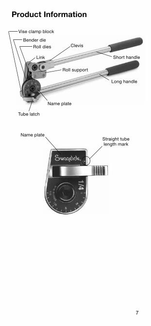
Product Information
Clevis
Link
Roll dies
Bender die
Vise clamp block
Name plate
Tube latch
Roll support
Long handle
Short handle
Name plateStraight tube length mark
8
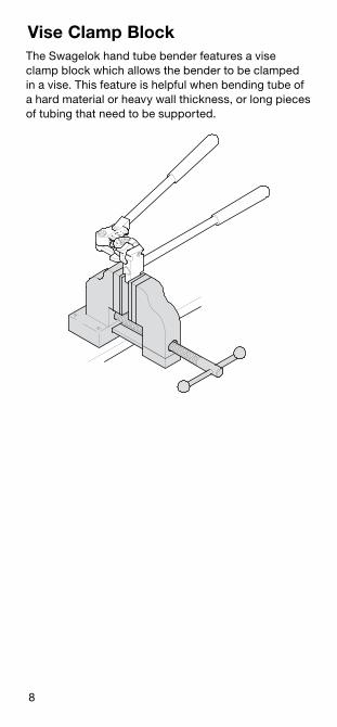
Vise Clamp BlockThe Swagelok hand tube bender features a vise clamp block which allows the bender to be clamped in a vise . This feature is helpful when bending tube of a hard material or heavy wall thickness, or long pieces of tubing that need to be supported .
9
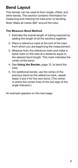
Bend LayoutThis bender can be used to form single, offset, and other bends . This section contains information for measuring and marking the tube prior to bending .
Note: Make all marks 360° around the tube .
The Measure-Bend Method
1 . Estimate the overall length of tubing required by adding the length of all the sections together .
2 . Place a reference mark at the end of the tube from which you are beginning the measurement .
3 . Measure from the reference mark and make a bend mark on the tube at a distance equal to the desired bend length . This mark indicates the vertex of the bend .
4 . See Using the Bender, page 12, to bend the tube .
5 . For additional bends, use the vertex of the previous bend as the reference mark, repeat steps 3 and 4 for the next bend . (The vertex is where the center lines of the two legs of the angle intersect .)
An example appears on the next page .
10
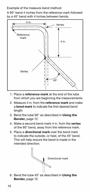
Example of the measure‑bend method:
A 90° bend 4 inches from the reference mark followed by a 45° bend with 4 inches between bends .
1 . Place a reference mark at the end of the tube from which you are beginning the measurements .
2 . Measure 4 in . from the reference mark and make a bend mark to indicate the first desired bend length .
3 . Bend the tube 90° as described in Using the Bender, page 12 .
4 . Make a second bend mark 4 in . from the vertex of the 90° bend, away from the reference mark .
5 . Place a directional mark over the bend mark to indicate the outside, or heel, of the 45° bend . This will help ensure the bend is made in the intended direction .
6 . Bend the tube 45° as described in Using the Bender, page 12 .
Directional mark
Second 90 Bend.eps
4 in .
Vertex
45°
Vertex
Reference mark
4 in .
11
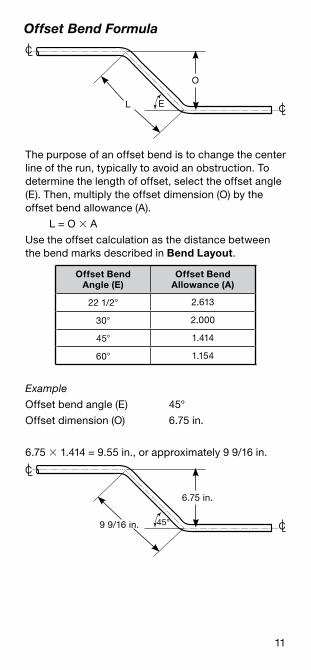
Offset Bend Formula
The purpose of an offset bend is to change the center line of the run, typically to avoid an obstruction . To determine the length of offset, select the offset angle (E) . Then, multiply the offset dimension (O) by the offset bend allowance (A) .
L = O A
Use the offset calculation as the distance between the bend marks described in Bend Layout .
Offset Bend Angle (E)
Offset Bend Allowance (A)
22 1/2 2 .613
30 2 .000
45 1 .414
60 1 .154
Example
Offset bend angle (E) 45°
Offset dimension (O) 6 .75 in .
6 .75 1 .414 = 9 .55 in ., or approximately 9 9/16 in .
C
C
O
L E
C
C
6 .75 in .
9 9/16 in . 45°
12
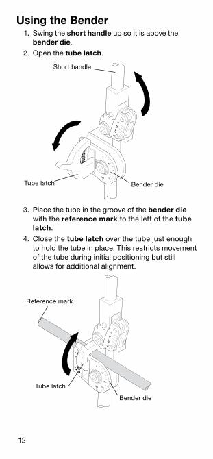
3 . Place the tube in the groove of the bender die with the reference mark to the left of the tube latch .
4 . Close the tube latch over the tube just enough to hold the tube in place . This restricts movement of the tube during initial positioning but still allows for additional alignment .
Short handle
Bender dieTube latch
Using the Bender 1 . Swing the short handle up so it is above the
bender die .
2 . Open the tube latch .
Bender die
Reference mark
Tube latch
13
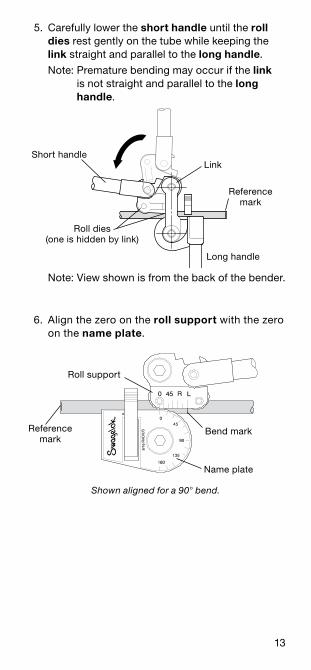
5 . Carefully lower the short handle until the roll dies rest gently on the tube while keeping the link straight and parallel to the long handle .
Note: Premature bending may occur if the link is not straight and parallel to the long handle .
6 . Align the zero on the roll support with the zero on the name plate .
Short handle
Long handle
Reference mark
Link
Roll dies (one is hidden by link)
Shown aligned for a 90 bend.
Note: View shown is from the back of the bender .
Name plate
Roll support
Reference mark
Bend mark
14
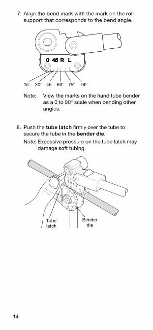
8 . Push the tube latch firmly over the tube to secure the tube in the bender die .
Note: Excessive pressure on the tube latch may damage soft tubing .
7 . Align the bend mark with the mark on the roll support that corresponds to the bend angle .
Tube latch
Bender die
Note: View the marks on the hand tube bender as a 0 to 90 scale when bending other angles .
15 30 60 75 9045
15
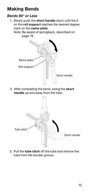
2 . After completing the bend, swing the short handle up and away from the tube .
1 . Slowly push the short handle down until the 0 on the roll support reaches the desired degree mark on the name plate . Note: Be aware of springback, described on
page 19 .
Making BendsBends 90° or Less
3 . Pull the tube latch off the tube and remove the tube from the bender groove .
Short handle
Roll support
Name plate
Short handle
Tube latch
16
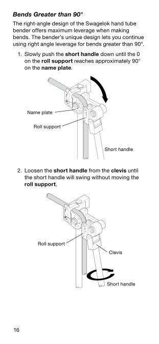
Bends Greater than 90°The right‑angle design of the Swagelok hand tube bender offers maximum leverage when making bends . The bender’s unique design lets you continue using right angle leverage for bends greater than 90° .
1 . Slowly push the short handle down until the 0 on the roll support reaches approximately 90 on the name plate .
2 . Loosen the short handle from the clevis until the short handle will swing without moving the roll support .
Short handle
Roll support
Name plate
Short handle
Roll support
Clevis
17
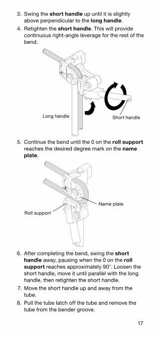
3 . Swing the short handle up until it is slightly above perpendicular to the long handle .
4 . Retighten the short handle . This will provide continuous right‑angle leverage for the rest of the bend .
5 . Continue the bend until the 0 on the roll support reaches the desired degree mark on the name plate .
6 . After completing the bend, swing the short handle away, pausing when the 0 on the roll support reaches approximately 90 . Loosen the short handle, move it until parallel with the long handle, then retighten the short handle .
7 . Move the short handle up and away from the tube .
8 . Pull the tube latch off the tube and remove the tube from the bender groove .
Long handle Short handle
Roll support
Name plate
18
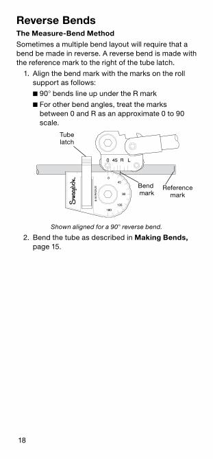
Reverse BendsThe Measure-Bend Method
Sometimes a multiple bend layout will require that a bend be made in reverse . A reverse bend is made with the reference mark to the right of the tube latch .
1 . Align the bend mark with the marks on the roll support as follows:
■ 90 bends line up under the R mark
■ For other bend angles, treat the marks between 0 and R as an approximate 0 to 90 scale .
Shown aligned for a 90 reverse bend.
2 . Bend the tube as described in Making Bends, page 15 .
Tube latch
Reference mark
Bend mark
19
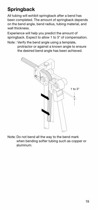
All tubing will exhibit springback after a bend has been completed . The amount of springback depends on the bend angle, bend radius, tubing material, and wall thickness .
Experience will help you predict the amount of springback . Expect to allow 1 to 3° of compensation .
Note : Verify the bend angle using a template, protractor or against a known angle to ensure the desired bend angle has been achieved .
Springback
Note: Do not bend all the way to the bend mark when bending softer tubing such as copper or aluminum .
1 to 3°
20
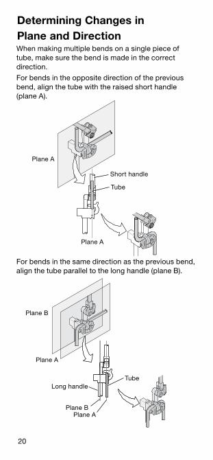
Determining Changes inPlane and DirectionWhen making multiple bends on a single piece of tube, make sure the bend is made in the correct direction .
For bends in the opposite direction of the previous bend, align the tube with the raised short handle (plane A) .
For bends in the same direction as the previous bend, align the tube parallel to the long handle (plane B) .
Plane A
Plane A
Short handle
Tube
Plane B
Plane A
Plane BPlane A
Long handleTube
21
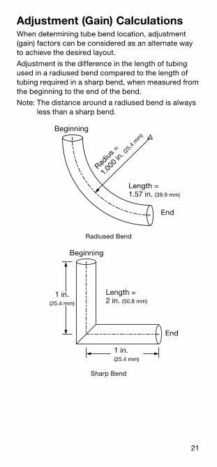
Adjustment (Gain) CalculationsWhen determining tube bend location, adjustment (gain) factors can be considered as an alternate way to achieve the desired layout .
Adjustment is the difference in the length of tubing used in a radiused bend compared to the length of tubing required in a sharp bend, when measured from the beginning to the end of the bend .
Note: The distance around a radiused bend is always less than a sharp bend .
Radiused Bend
Sharp Bend
Beginning
End
Radius
=
1 .000
in . (2
5 .4
mm
)
Length =1 .57 in . (39 .9 mm)
Length =2 in . (50 .8 mm)
1 in .(25 .4 mm)
Beginning
End
1 in .(25 .4 mm)
22
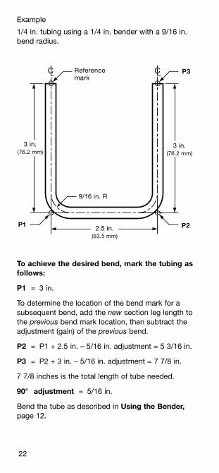
To achieve the desired bend, mark the tubing as follows:
P1 = 3 in .
To determine the location of the bend mark for a subsequent bend, add the new section leg length to the previous bend mark location, then subtract the adjustment (gain) of the previous bend .
P2 = P1 + 2 .5 in . – 5/16 in . adjustment = 5 3/16 in .
P3 = P2 + 3 in . – 5/16 in . adjustment = 7 7/8 in .
7 7/8 inches is the total length of tube needed .
90° adjustment = 5/16 in .
Bend the tube as described in Using the Bender, page 12 .
Example
1/4 in . tubing using a 1/4 in . bender with a 9/16 in . bend radius .
Crawford Hand Tube Bender MS-13-43 C-ELD-334
Reference mark
3 in .(76 .2 mm)
3 in .(76 .2 mm)
9/16 in . R
2 .5 in .(63 .5 mm)
P1 P2
P3C C
23
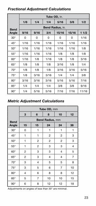
Fractional Adjustment Calculations
Metric Adjustment Calculations
Adjustments on angles of less than 30° are minimal .
Bend Angle
Tube OD, in .
1/8 1/4 1/4 5/16 3/8 1/2
Bend Radius, in .
9/16 9/16 3/4 15/16 15/16 1 1/2
30° 0 0 0 0 0 1/16
45° 1/16 1/16 1/16 1/16 1/16 1/16
50° 1/16 1/16 1/16 1/16 1/16 1/8
55° 1/16 1/16 1/16 1/8 1/8 1/8
60° 1/16 1/8 1/16 1/8 1/8 3/16
65° 1/8 1/8 1/8 3/16 1/8 1/4
70° 1/8 1/8 1/8 3/16 3/16 5/16
75° 1/8 3/16 3/16 1/4 1/4 3/8
80° 3/16 3/16 3/16 5/16 5/16 7/16
85° 1/4 1/4 1/4 3/8 3/8 9/16
90° 1/4 5/16 5/16 7/16 7/16 11/16
Bend Angle
Tube OD, mm
3 6 8 10 12
Bend Radius, mm
15 15 24 24 38
30° 0 1 1 1 1
45° 1 1 2 2 3
50° 1 2 2 2 3
55° 1 2 3 3 4
60° 2 3 3 4 5
65° 2 3 4 4 7
70° 3 4 5 5 8
75° 3 5 6 7 10
80° 4 6 8 8 12
85° 5 7 10 10 15
90° 6 8 12 12 18
24
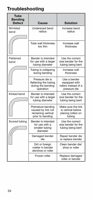
TroubleshootingTube
Bending Defect Cause Solution
Wrinkled bend
Undersized bend radius
Increase bend radius
Tube wall thickness too thin
Increase wall thickness
Flattened bend
Bender is intended for use with a larger
tubing diameter
Use the correct size bender for the tubing being bent
Tubing is collapsing during bending
Increase wall thickness
Pressure die is flattening the tubing during the bending
operation
Use a bender equipped with
rollers instead of a pressure die
Kinked bend Bender is intended for use with a larger
tubing diameter
Use the correct size bender for the tubing being bent
Premature bending caused by link not remaining vertical prior to bending
Make sure the link is vertical before placing rollers on
tubing
Scored tubing Bender is intended for use with a smaller tubing
diameter
Use the correct size bender for the tubing being bent
Damaged bender die
Repair bender die or replace bender
Dirt or foreign matter in bender die/shoe or roller
Clean bender die/shoe or roller
Frozen roller Replace damaged roller or bender
25
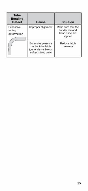
Tube Bending Defect Cause Solution
Excessive tubing deformation
Improper alignment Make sure that the bender die and bend shoe are
aligned
Excessive pressure on the tube latch
(generally visible on softer tubing only)
Reduce latch pressure
26
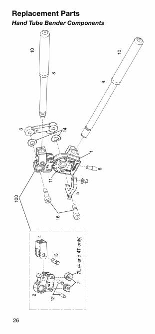
Replacement PartsHand Tube Bender Components
1
102
5
3
4
6
7
8
9
1211
13
14
15
16
100
10
7L (4
and
4T
onl
y)
27
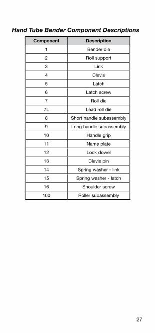
Hand Tube Bender Component Descriptions
Component Description
1 Bender die
2 Roll support
3 Link
4 Clevis
5 Latch
6 Latch screw
7 Roll die
7L Lead roll die
8 Short handle subassembly
9 Long handle subassembly
10 Handle grip
11 Name plate
12 Lock dowel
13 Clevis pin
14 Spring washer ‑ link
15 Spring washer ‑ latch
16 Shoulder screw
100 Roller subassembly
28
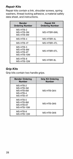
Repair KitsRepair kits contain a link, shoulder screws, spring washers, thread locking adhesive, a material safety data sheet, and instructions .
Bender Ordering Number
Repair Kit Ordering Number
MS‑HTB‑2 MS‑HTB‑3M MS‑HTB‑6M
MS‑HTBR‑6ML
MS‑HTB‑4 MS‑HTBR‑4L
MS‑HTB‑4T MS‑HTBR‑4TL
MS‑HTB‑5 MS‑HTB‑8M MS‑HTB‑6T MS‑HTB‑10M
MS‑HTBR‑6TL
MS‑HTB‑8 MS‑HTB‑12M MS‑HTBR‑8L
Grip KitsGrip kits contain two handle grips .
Bender Ordering Number
Grip Kit Ordering Number
MS‑HTB‑2 MS‑HTB‑3M MS‑HTB‑6M MS‑HTB‑4 MS‑HTB‑4T
MS‑HTB‑GK4
MS‑HTB‑5 MS‑HTB‑8M MS‑HTB‑6T MS‑HTB‑10M
MS‑HTB‑GK6
MS‑HTB‑8 MS‑HTB‑12M MS‑HTB‑GK8
29
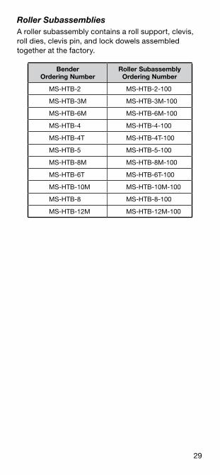
Roller SubassembliesA roller subassembly contains a roll support, clevis, roll dies, clevis pin, and lock dowels assembled together at the factory .
Bender Ordering Number
Roller Subassembly Ordering Number
MS‑HTB‑2 MS‑HTB‑2‑100
MS‑HTB‑3M MS‑HTB‑3M‑100
MS‑HTB‑6M MS‑HTB‑6M‑100
MS‑HTB‑4 MS‑HTB‑4‑100
MS‑HTB‑4T MS‑HTB‑4T‑100
MS‑HTB‑5 MS‑HTB‑5‑100
MS‑HTB‑8M MS‑HTB‑8M‑100
MS‑HTB‑6T MS‑HTB‑6T‑100
MS‑HTB‑10M MS‑HTB‑10M‑100
MS‑HTB‑8 MS‑HTB‑8‑100
MS‑HTB‑12M MS‑HTB‑12M‑100
30
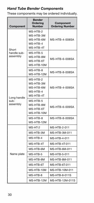
Hand Tube Bender ComponentsThese components may be ordered individually .
Component
Bender Ordering Number
Component Ordering Number
Short handle sub‑assembly
MS‑HTB‑2MS‑HTB‑3MMS‑HTB‑6MMS‑HTB‑4MS‑HTB‑4T
MS‑HTB‑4‑008SA
MS‑HTB‑5MS‑HTB‑8MMS‑HTB‑6TMS‑HTB‑10M
MS‑HTB‑6‑008SA
MS‑HTB‑8MS‑HTB‑12M
MS‑HTB‑8‑008SA
Long handle sub‑assembly
MS‑HTB‑2MS‑HTB‑3MMS‑HTB‑6MMS‑HTB‑4MS‑HTB‑4T
MS‑HTB‑4‑009SA
MS‑HTB‑5MS‑HTB‑8MMS‑HTB‑6TMS‑HTB‑10M
MS‑HTB‑6‑009SA
MS‑HTB‑8MS‑HTB‑12M
MS‑HTB‑8‑009SA
Name plate
MS‑HT‑2 MS‑HTB‑2‑011
MS‑HTB‑3M MS‑HTB‑3M‑011
MS‑HTB‑4 MS‑HTB‑4‑011
MS‑HTB‑4T MS‑HTB‑4T‑011
MS‑HTB‑6M MS‑HTB‑6M‑011
MS‑HTB‑5 MS‑HTB‑5‑011
MS‑HTB‑8M MS‑HTB‑8M‑011
MS‑HTB‑6T MS‑HTB‑6T‑011
MS‑HTB‑10M MS‑HTB‑10M‑011
MS‑HTB‑8 MS‑HTB‑8‑011S
MS‑HTB‑12M MS‑HTB‑12M‑011S
31
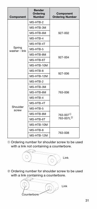
Component
Bender Ordering Number
Component Ordering Number
Spring washer ‑ link
MS‑HTB‑2
927‑002
MS‑HTB‑3M
MS‑HTB‑6M
MS‑HTB‑4
MS‑HTB‑4T
MS‑HTB‑5
927‑004MS‑HTB‑8M
MS‑HTB‑6T
MS‑HTB‑10M
MS‑HTB‑8927‑006
MS‑HTB‑12M
Shoulder screw
MS‑HTB‑2
763‑006
MS‑HTB‑3M
MS‑HTB‑6M
MS‑HTB‑4
MS‑HTB‑4T
MS‑HTB‑5
763‑007➀
763‑007L➁
MS‑HTB‑8M
MS‑HTB‑6T
MS‑HTB‑10M
MS‑HTB‑8763‑008
MS‑HTB‑12M
➀ Ordering number for shoulder screw to be used with a link not containing a counterbore .
➁ Ordering number for shoulder screw to be used with a link containing a counterbore .
Link
Counterbore
Link

Swagelok—TM Swagelok Company© 2009–2012 Swagelok CompanyPrinted in U .S .A ., AGSJuly 2012, R4MS‑13‑43