Embed Size (px)
Citation preview
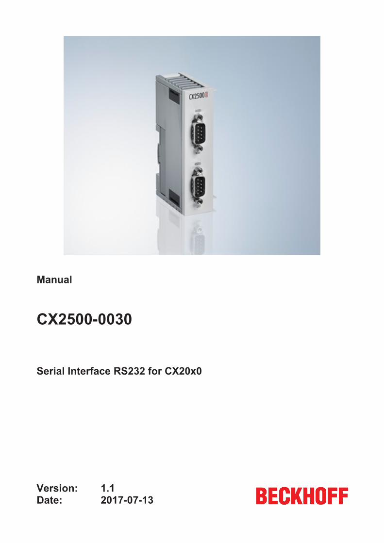
Manual
CX2500-0030
Serial Interface RS232 for CX20x0
1.12017-07-13
Version:Date:

Table of contents
CX2500-0030 3Version: 1.1
Table of contents1 Foreword .................................................................................................................................................... 5
1.1 Notes on the documentation........................................................................................................... 51.2 Safety instructions .......................................................................................................................... 61.3 Documentation issue state ............................................................................................................. 7
2 Product overview....................................................................................................................................... 82.1 Intended use ................................................................................................................................... 82.2 System overview............................................................................................................................. 92.3 CX2500-0030 - Technical data ....................................................................................................... 9
3 Mounting and wiring ............................................................................................................................... 103.1 Unpacking, installation and transport............................................................................................ 103.2 Dimensions ................................................................................................................................... 113.3 Attaching the system interface to the CX20x0 system ................................................................. 123.4 Installation on the mounting rail .................................................................................................... 133.5 Mounting the module lock............................................................................................................. 153.6 CX2500-0030 connections ........................................................................................................... 17
4 Commissioning / Configuration ............................................................................................................. 194.1 Switching on and off ..................................................................................................................... 194.2 PLC-Interface CX2500-0030 ........................................................................................................ 20
5 Error handling and diagnostics ............................................................................................................. 225.1 Faults ............................................................................................................................................ 22
6 Decommissioning.................................................................................................................................... 236.1 Disassembly and disposal ............................................................................................................ 23
7 Appendix .................................................................................................................................................. 257.1 Certifications ................................................................................................................................. 257.2 Support and Service ..................................................................................................................... 26
Table of contents
CX2500-00304 Version: 1.1
Foreword
CX2500-0030 5Version: 1.1
1 Foreword
1.1 Notes on the documentationThis description is only intended for the use of trained specialists in control and automation engineering whoare familiar with the applicable national standards.It is essential that the documentation and the following notes and explanations are followed when installingand commissioning the components. It is the duty of the technical personnel to use the documentation published at the respective time of eachinstallation and commissioning.
The responsible staff must ensure that the application or use of the products described satisfy all therequirements for safety, including all the relevant laws, regulations, guidelines and standards.
Disclaimer
The documentation has been prepared with care. The products described are, however, constantly underdevelopment.We reserve the right to revise and change the documentation at any time and without prior announcement.No claims for the modification of products that have already been supplied may be made on the basis of thedata, diagrams and descriptions in this documentation.
Trademarks
Beckhoff®, TwinCAT®, EtherCAT®, Safety over EtherCAT®, TwinSAFE®, XFC® and XTS® are registeredtrademarks of and licensed by Beckhoff Automation GmbH.Other designations used in this publication may be trademarks whose use by third parties for their ownpurposes could violate the rights of the owners.
Patent Pending
The EtherCAT Technology is covered, including but not limited to the following patent applications andpatents:EP1590927, EP1789857, DE102004044764, DE102007017835with corresponding applications or registrations in various other countries.
The TwinCAT Technology is covered, including but not limited to the following patent applications andpatents:EP0851348, US6167425 with corresponding applications or registrations in various other countries.
EtherCAT® is registered trademark and patented technology, licensed by Beckhoff Automation GmbH,Germany
Copyright
© Beckhoff Automation GmbH & Co. KG, Germany.The reproduction, distribution and utilization of this document as well as the communication of its contents toothers without express authorization are prohibited.Offenders will be held liable for the payment of damages. All rights reserved in the event of the grant of apatent, utility model or design.
Foreword
CX2500-00306 Version: 1.1
1.2 Safety instructions
Safety regulations
Please note the following safety instructions and explanations!Product-specific safety instructions can be found on following pages or in the areas mounting, wiring,commissioning etc.
Exclusion of liability
All the components are supplied in particular hardware and software configurations appropriate for theapplication. Modifications to hardware or software configurations other than those described in thedocumentation are not permitted, and nullify the liability of Beckhoff Automation GmbH & Co. KG.
Personnel qualification
This description is only intended for trained specialists in control, automation and drive engineering who arefamiliar with the applicable national standards.
Description of symbols
In this documentation the following symbols are used with an accompanying safety instruction or note. Thesafety instructions must be read carefully and followed without fail!
DANGER
Serious risk of injury!Failure to follow the safety instructions associated with this symbol directly endangers thelife and health of persons.
WARNING
Risk of injury!Failure to follow the safety instructions associated with this symbol endangers the life andhealth of persons.
CAUTION
Personal injuries!Failure to follow the safety instructions associated with this symbol can lead to injuries topersons.
Attention
Damage to the environment or devicesFailure to follow the instructions associated with this symbol can lead to damage to the en-vironment or equipment.
Note
Tip or pointerThis symbol indicates information that contributes to better understanding.
Foreword
CX2500-0030 7Version: 1.1
1.3 Documentation issue stateVersion Changes1.0 first version1.1 Technical data updated
Product overview
CX2500-00308 Version: 1.1
2 Product overview
2.1 Intended useThe CX20x0 device series is a modular control system designed for DIN rail installation. The system isscalable, so that the required modules can be assembled and installed in the control cabinet or terminal boxas required.
Only switch the PC off after closing the software
Before the Embedded PC is switched off, the software currently running on it should be stopped properly inorder to avoid data loss on the hard disk. Please read the section on “Switching off”.
Switch off all system components and uncouple the Industrial PC from the system if the PC is not used forcontrol purposes, e.g. during a function test. To disconnect first pull the first terminal behind the powersupply unit (optional), then pull the connectors of the fieldbus connections.System components that have been switched off must be secured against being switched on again.
The Embedded PC’s power supply unit must be supplied with 24 VDC.
Attention
Damage to the environment or devicesDo not exchange any parts when under power! The exchange of controller parts when livecan lead to short-circuits or overvoltages. These can damage the controller itself and con-nected peripherals (terminals, monitors, input devices, etc.).
When components are being fitted or removed, the supply voltage must be switched off.
Software knowledge
Attention
System malfunctionsMandatory software knowledge! Every user must be familiar with any of the functions of thesoftware installed on the PC that he can reach.
Product overview
CX2500-0030 9Version: 1.1
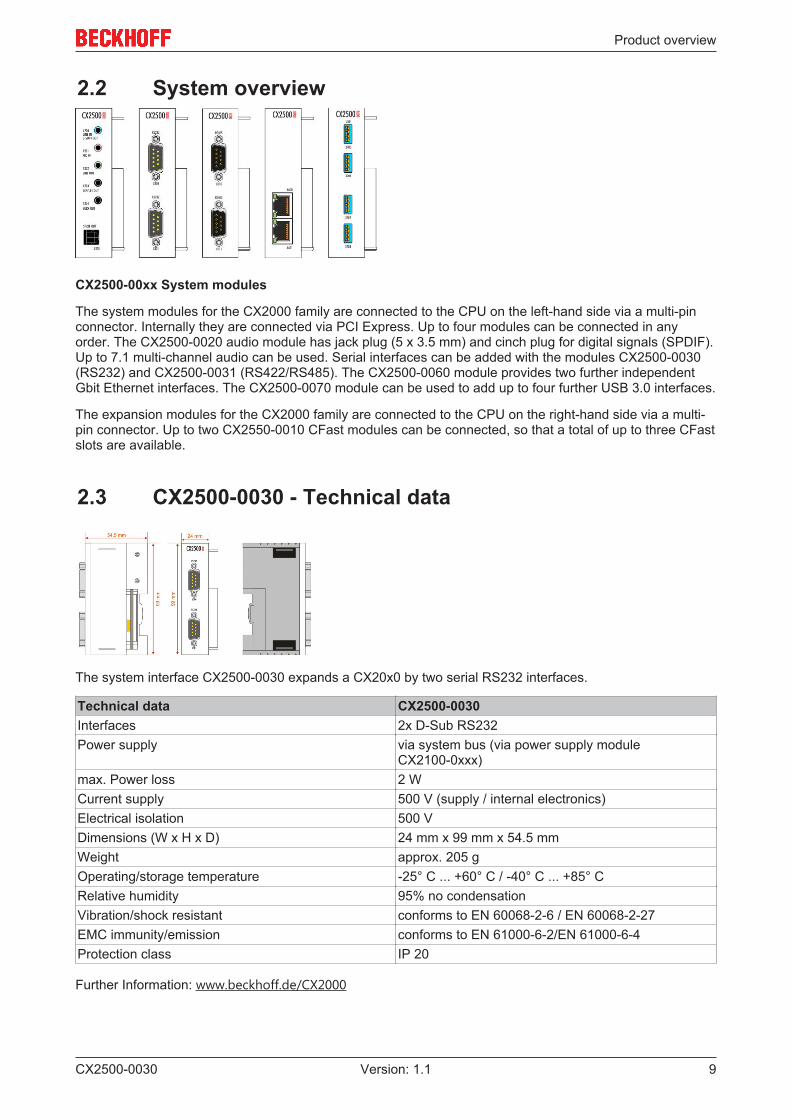
2.2 System overview
CX2500-00xx System modules
The system modules for the CX2000 family are connected to the CPU on the left-hand side via a multi-pinconnector. Internally they are connected via PCI Express. Up to four modules can be connected in anyorder. The CX2500-0020 audio module has jack plug (5 x 3.5 mm) and cinch plug for digital signals (SPDIF).Up to 7.1 multi-channel audio can be used. Serial interfaces can be added with the modules CX2500-0030(RS232) and CX2500-0031 (RS422/RS485). The CX2500-0060 module provides two further independentGbit Ethernet interfaces. The CX2500-0070 module can be used to add up to four further USB 3.0 interfaces.
The expansion modules for the CX2000 family are connected to the CPU on the right-hand side via a multi-pin connector. Up to two CX2550-0010 CFast modules can be connected, so that a total of up to three CFastslots are available.
2.3 CX2500-0030 - Technical data
The system interface CX2500-0030 expands a CX20x0 by two serial RS232 interfaces.
Technical data CX2500-0030Interfaces 2x D-Sub RS232Power supply via system bus (via power supply module
CX2100-0xxx)max. Power loss 2 WCurrent supply 500 V (supply / internal electronics)Electrical isolation 500 VDimensions (W x H x D) 24 mm x 99 mm x 54.5 mmWeight approx. 205 gOperating/storage temperature -25° C ... +60° C / -40° C ... +85° CRelative humidity 95% no condensationVibration/shock resistant conforms to EN 60068-2-6 / EN 60068-2-27EMC immunity/emission conforms to EN 61000-6-2/EN 61000-6-4Protection class IP 20
Further Information: www.beckhoff.de/CX2000
Mounting and wiring
CX2500-003010 Version: 1.1
3 Mounting and wiring
3.1 Unpacking, installation and transportThe specified storage conditions must be adhered to (see "Technical data").
Dimensions and weight of the individual modules
Dimensions (W x H x D): 24 mm x 99 mm x 54.5 mm
Weight: approx. 205 g (system interface)
Unpacking
Proceed as follows to unpack the unit:
1. Remove packaging.2. Do not discard the original packaging. Keep it for transporting the device in the future.3. Check the delivery for completeness by comparing it with your order.4. Please keep the associated paperwork. It contains important information for handling the unit.5. Check the contents for visible shipping damage.6. If you notice any shipping damage or inconsistencies between the contents and your order, you
should notify Beckhoff Service.
Attention
Danger of damage to the device!During transport in cold conditions, or if the device is subjected to extreme temperature dif-ferences, condensation on and inside the device must be avoided. Prior to operation, thedevice must be allowed to slowly adjust to room temperature. Should condensation occur,a delay time of approximately 12 hours must be allowed before the unit is switched on.
Installation
The devices are designed for installation in control cabinets.
Shipping and relocation
Despite the robust design of the unit, the components are sensitive to strong vibrations and impacts. Duringtransport, your computer should therefore be protected from excessive mechanical stress. Therefore, pleaseuse the original packaging.
Mounting and wiring
CX2500-0030 11Version: 1.1
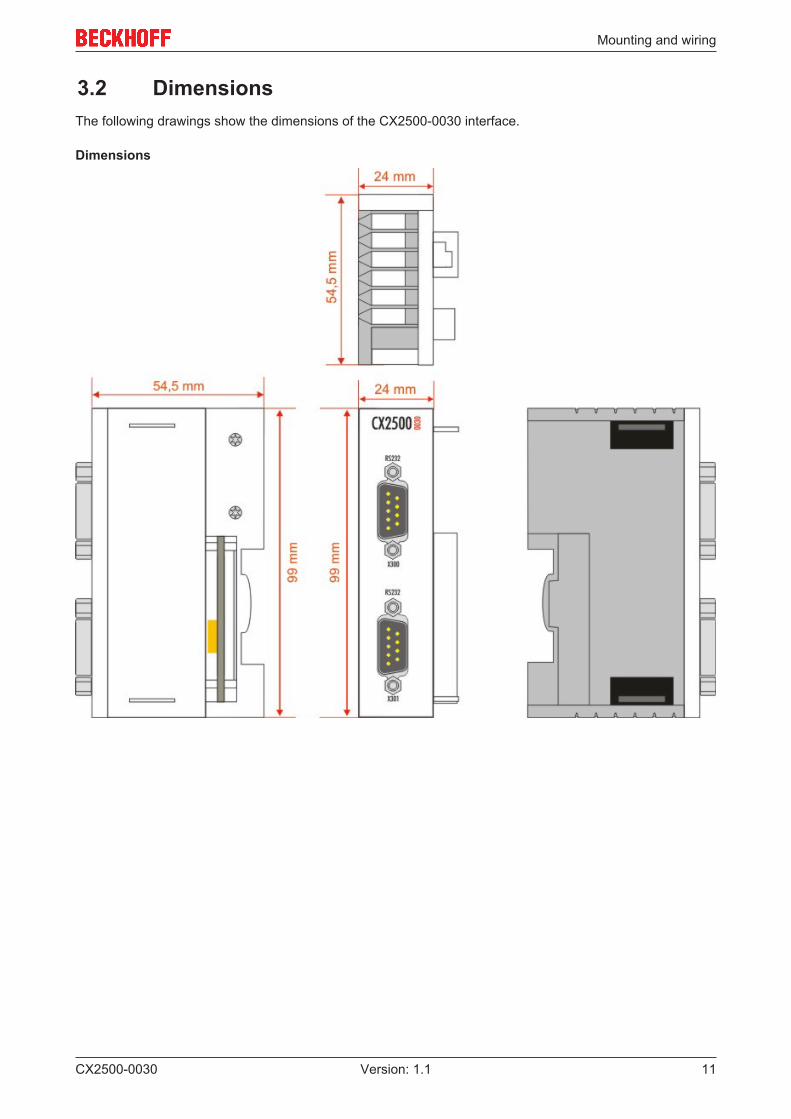
3.2 DimensionsThe following drawings show the dimensions of the CX2500-0030 interface.
Dimensions
Mounting and wiring
CX2500-003012 Version: 1.1
3.3 Attaching the system interface to the CX20x0 system
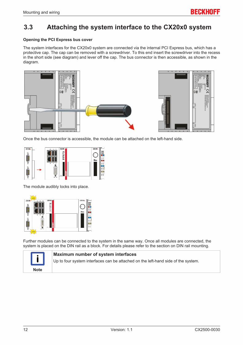
Opening the PCI Express bus cover
The system interfaces for the CX20x0 system are connected via the internal PCI Express bus, which has aprotective cap. The cap can be removed with a screwdriver. To this end insert the screwdriver into the recessin the short side (see diagram) and lever off the cap. The bus connector is then accessible, as shown in thediagram.
Once the bus connector is accessible, the module can be attached on the left-hand side.
The module audibly locks into place.
Further modules can be connected to the system in the same way. Once all modules are connected, thesystem is placed on the DIN rail as a block. For details please refer to the section on DIN rail mounting.
Note
Maximum number of system interfacesUp to four system interfaces can be attached on the left-hand side of the system.
Mounting and wiring
CX2500-0030 13Version: 1.1
3.4 Installation on the mounting rail
Snapping onto the mounting rail
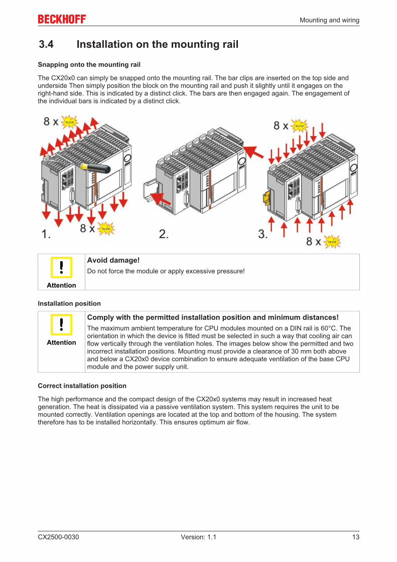
The CX20x0 can simply be snapped onto the mounting rail. The bar clips are inserted on the top side andunderside Then simply position the block on the mounting rail and push it slightly until it engages on theright-hand side. This is indicated by a distinct click. The bars are then engaged again. The engagement ofthe individual bars is indicated by a distinct click.
Attention
Avoid damage!Do not force the module or apply excessive pressure!
Installation position
Attention
Comply with the permitted installation position and minimum distances!The maximum ambient temperature for CPU modules mounted on a DIN rail is 60°C. Theorientation in which the device is fitted must be selected in such a way that cooling air canflow vertically through the ventilation holes. The images below show the permitted and twoincorrect installation positions. Mounting must provide a clearance of 30 mm both aboveand below a CX20x0 device combination to ensure adequate ventilation of the base CPUmodule and the power supply unit.
Correct installation position
The high performance and the compact design of the CX20x0 systems may result in increased heatgeneration. The heat is dissipated via a passive ventilation system. This system requires the unit to bemounted correctly. Ventilation openings are located at the top and bottom of the housing. The systemtherefore has to be installed horizontally. This ensures optimum air flow.
Mounting and wiring
CX2500-003014 Version: 1.1
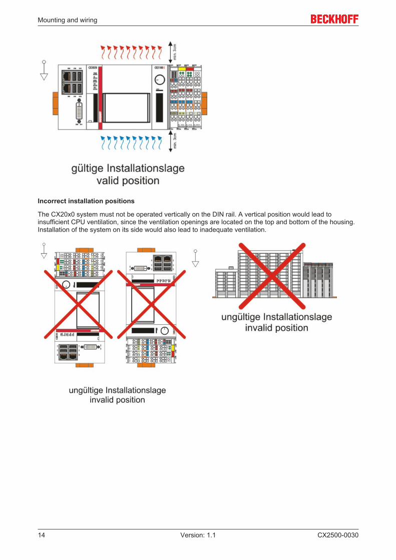
Incorrect installation positions
The CX20x0 system must not be operated vertically on the DIN rail. A vertical position would lead toinsufficient CPU ventilation, since the ventilation openings are located on the top and bottom of the housing.Installation of the system on its side would also lead to inadequate ventilation.
Mounting and wiring
CX2500-0030 15Version: 1.1
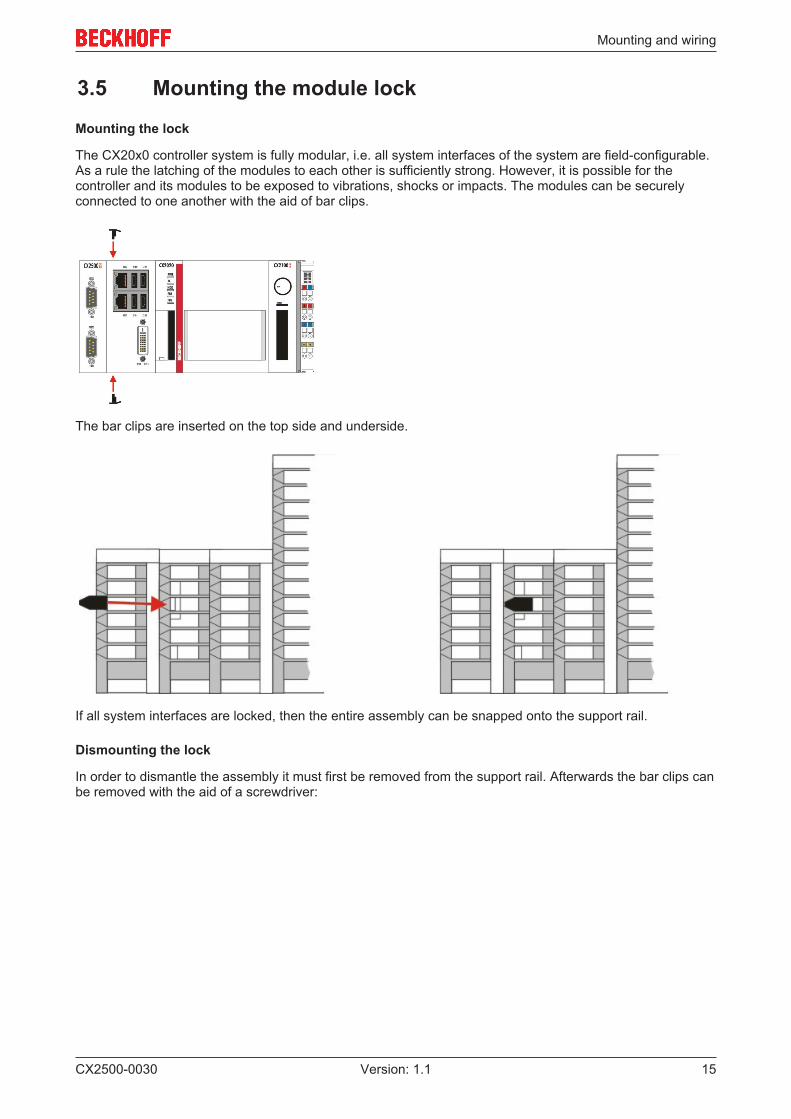
3.5 Mounting the module lock
Mounting the lock
The CX20x0 controller system is fully modular, i.e. all system interfaces of the system are field-configurable.As a rule the latching of the modules to each other is sufficiently strong. However, it is possible for thecontroller and its modules to be exposed to vibrations, shocks or impacts. The modules can be securelyconnected to one another with the aid of bar clips.
The bar clips are inserted on the top side and underside.
If all system interfaces are locked, then the entire assembly can be snapped onto the support rail.
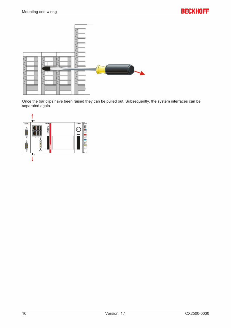
Dismounting the lock
In order to dismantle the assembly it must first be removed from the support rail. Afterwards the bar clips canbe removed with the aid of a screwdriver:
Mounting and wiring
CX2500-003016 Version: 1.1
Once the bar clips have been raised they can be pulled out. Subsequently, the system interfaces can beseparated again.
Mounting and wiring
CX2500-0030 17Version: 1.1
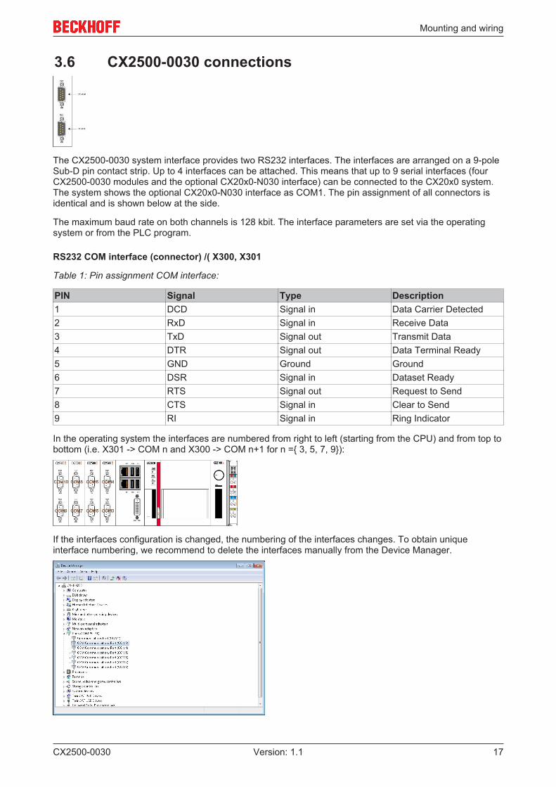
3.6 CX2500-0030 connections
The CX2500-0030 system interface provides two RS232 interfaces. The interfaces are arranged on a 9-poleSub-D pin contact strip. Up to 4 interfaces can be attached. This means that up to 9 serial interfaces (fourCX2500-0030 modules and the optional CX20x0-N030 interface) can be connected to the CX20x0 system.The system shows the optional CX20x0-N030 interface as COM1. The pin assignment of all connectors isidentical and is shown below at the side.
The maximum baud rate on both channels is 128 kbit. The interface parameters are set via the operatingsystem or from the PLC program.
RS232 COM interface (connector) /( X300, X301
Table 1: Pin assignment COM interface:
PIN Signal Type Description1 DCD Signal in Data Carrier Detected2 RxD Signal in Receive Data3 TxD Signal out Transmit Data4 DTR Signal out Data Terminal Ready5 GND Ground Ground6 DSR Signal in Dataset Ready7 RTS Signal out Request to Send8 CTS Signal in Clear to Send9 RI Signal in Ring Indicator
In the operating system the interfaces are numbered from right to left (starting from the CPU) and from top tobottom (i.e. X301 -> COM n and X300 -> COM n+1 for n ={ 3, 5, 7, 9}):
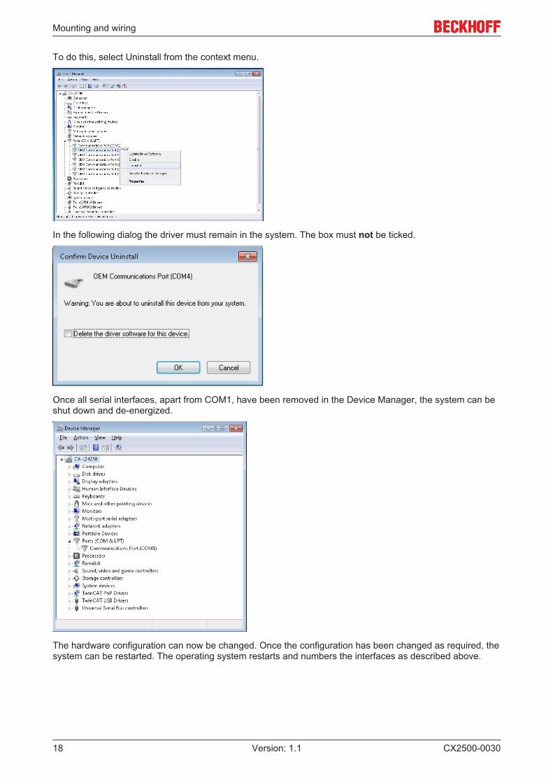
If the interfaces configuration is changed, the numbering of the interfaces changes. To obtain uniqueinterface numbering, we recommend to delete the interfaces manually from the Device Manager.
Mounting and wiring
CX2500-003018 Version: 1.1
To do this, select Uninstall from the context menu.
In the following dialog the driver must remain in the system. The box must not be ticked.
Once all serial interfaces, apart from COM1, have been removed in the Device Manager, the system can beshut down and de-energized.
The hardware configuration can now be changed. Once the configuration has been changed as required, thesystem can be restarted. The operating system restarts and numbers the interfaces as described above.
Commissioning / Configuration
CX2500-0030 19Version: 1.1
4 Commissioning / Configuration
4.1 Switching on and off
Switching on
The power supply for the basic CPU module comes from the power supply unit. The basic CPU modulestarts automatically when the power supply unit is connected to the mains.
Switching on for the first time
When you switch on the PC for the first time, the pre-installed operating system (optional) will be started.
Switching off
The Embedded PC switches off when the power supply unit is switched off. The control software typicallyrunning on Embedded PCs should be shut down or stopped correctly. A user who may not close softwaremay also not switch the Embedded PC off, since data can be lost from the hard disk by switching off whilesoftware is running.
Once the software has been stopped, the operating system can be shut down. Only then should the powersupply be interrupted.
Commissioning / Configuration
CX2500-003020 Version: 1.1
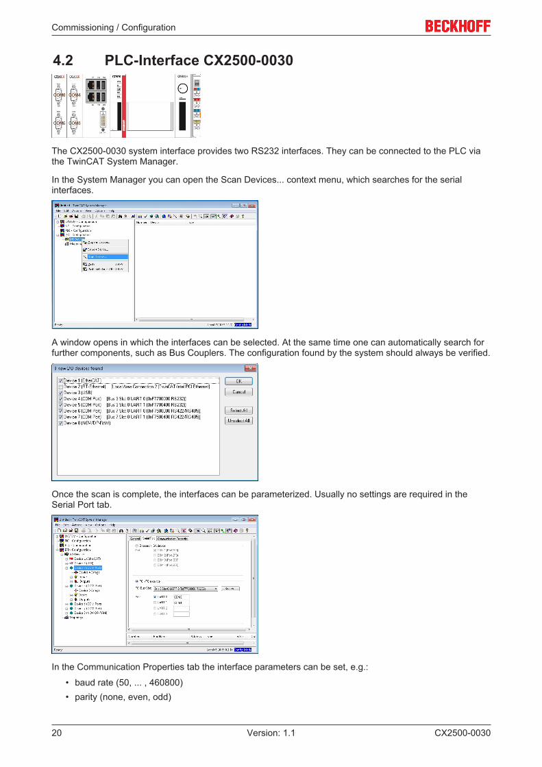
4.2 PLC-Interface CX2500-0030
The CX2500-0030 system interface provides two RS232 interfaces. They can be connected to the PLC viathe TwinCAT System Manager.
In the System Manager you can open the Scan Devices... context menu, which searches for the serialinterfaces.
A window opens in which the interfaces can be selected. At the same time one can automatically search forfurther components, such as Bus Couplers. The configuration found by the system should always be verified.
Once the scan is complete, the interfaces can be parameterized. Usually no settings are required in theSerial Port tab.
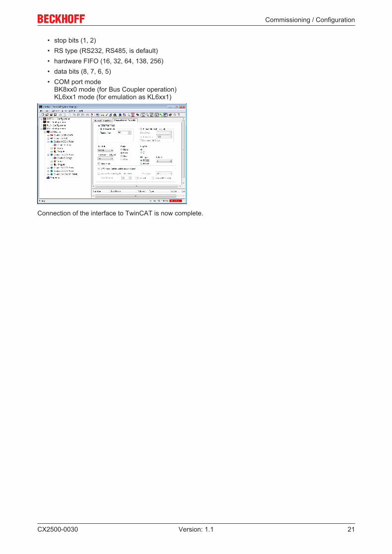
In the Communication Properties tab the interface parameters can be set, e.g.:
• baud rate (50, ... , 460800)• parity (none, even, odd)
Commissioning / Configuration
CX2500-0030 21Version: 1.1
• stop bits (1, 2)• RS type (RS232, RS485, is default)• hardware FIFO (16, 32, 64, 138, 256)• data bits (8, 7, 6, 5)• COM port mode
BK8xx0 mode (for Bus Coupler operation)KL6xx1 mode (for emulation as KL6xx1)
Connection of the interface to TwinCAT is now complete.
Error handling and diagnostics
CX2500-003022 Version: 1.1
5 Error handling and diagnostics
5.1 FaultsPlease also refer to the Safety instructions section.
Possible faults and their correction
Fault Cause Measuresno function after the Embedded PChas been switched on
no power supply for the EmbeddedPC other causes
1.Check the fuse2. Measure voltage at connection,check plug wiring, call Beckhoffsupport
Embedded PC does not boot fully Hard disk damaged (e.g. due toswitching off while software isrunning), incorrect setup, othercauses
Check setup Call Beckhoff Support
Computer boots, software starts,but control does not operatecorrectly
Cause of the fault is either in thesoftware or in parts of the plantoutside the Embedded PC
Call the manufacturer of themachine or the software.
CF card access error Faulty CFast card, faulty CFast slot Use a different CFast card to checkthe CFast slot Call BeckhoffSupport
Embedded PC only works partiallyor temporarily
Defective components in theEmbedded PC
Call Beckhoff support
Please make a note of the following information before contacting Beckhoff service or support:
1. Precise device ID: CXxxxx-xxxx2. Serial number3. Hardware version4. Any interfaces (N030, N031, B110, ...)5. TwinCAT version used6. Any components / software used
The quickest response will come from support / service in your country. Therefore please contact yourregional contact. For details please refer to our website at www.beckhoff.de or ask your distribution partner.
Decommissioning
CX2500-0030 23Version: 1.1
6 Decommissioning
6.1 Disassembly and disposal
The disassembly of a CX20x0 hardware configuration with system interfaces takes place in 3 steps
1. Switching off and disconnecting the power supply
Before a CX20x0 system can be dismantled, the system should be switched off, and the power supplyshould be disconnected.
2. Removing from the DIN rail
Before the individual modules are disconnected, the whole CX20x0 hardware block should be removed fromthe DIN rail. Proceed as follows:
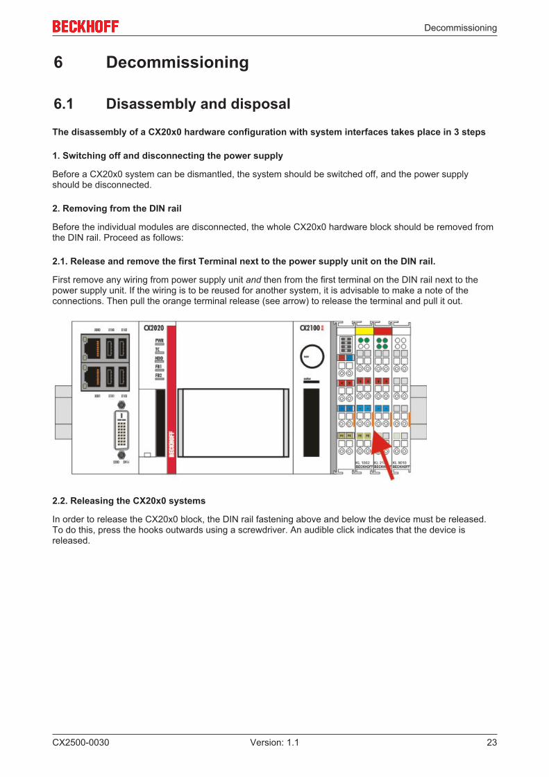
2.1. Release and remove the first Terminal next to the power supply unit on the DIN rail.
First remove any wiring from power supply unit and then from the first terminal on the DIN rail next to thepower supply unit. If the wiring is to be reused for another system, it is advisable to make a note of theconnections. Then pull the orange terminal release (see arrow) to release the terminal and pull it out.
2.2. Releasing the CX20x0 systems
In order to release the CX20x0 block, the DIN rail fastening above and below the device must be released.To do this, press the hooks outwards using a screwdriver. An audible click indicates that the device isreleased.

Decommissioning
CX2500-003024 Version: 1.1
After pulling on the terminal release of the power supply unit (see arrow) the block can be carefully removedfrom the DIN rail.
Disposal
The device must be fully dismantled in order to dispose of it.
Electronic parts must be disposed of in accordance with national electronics scrap regulations.
3. Disconnecting the system interface
Disconnecting the system modules from the basic module
If the modules are locked, i.e. attached with tie clips, the clips must be released. To this end lift the tie clipswith a screwdriver and pull them out. Subsequently, the system interfaces can be separated again.
Attention
Do not use force to open the device!Opening the module housing by force would destroy it. The devices may only be opened byBeckhoff service personnel.
Appendix
CX2500-0030 25Version: 1.1
7 Appendix
7.1 CertificationsAll products of the Embedded PC family are CE, UL and EAC certified. Since the product family iscontinuously developed further, we are unable to provide a full listing here. The current list of certifiedproducts can be found at www.beckhoff.com.
FCC Approvals for the United States of America
FCC: Federal Communications Commission Radio Frequency Interference Statement
This equipment has been tested and found to comply with the limits for a Class A digital device, pursuant toPart 15 of the FCC Rules. These limits are designed to provide reasonable protection against harmfulinterference when the equipment is operated in a commercial environment. This equipment generates, uses,and can radiate radio frequency energy and, if not installed and used in accordance with the instructionmanual, may cause harmful interference to radio communications. Operation of this equipment in aresidential area is likely to cause harmful interference in which case the user will be required to correct theinterference at his own expense.
FCC Approval for Canada
FCC: Canadian Notice
This equipment does not exceed the Class A limits for radiated emissions as described in the RadioInterference Regulations of the Canadian Department of Communications.
Appendix
CX2500-003026 Version: 1.1
7.2 Support and ServiceBeckhoff and their partners around the world offer comprehensive support and service, making available fastand competent assistance with all questions related to Beckhoff products and system solutions.
Beckhoff's branch offices and representatives
Please contact your Beckhoff branch office or representative for local support and service on Beckhoffproducts!
The addresses of Beckhoff's branch offices and representatives round the world can be found on her internetpages:http://www.beckhoff.com
You will also find further documentation for Beckhoff components there.
Beckhoff Headquarters
Beckhoff Automation GmbH & Co. KG
Huelshorstweg 2033415 VerlGermany
Phone: +49(0)5246/963-0Fax: +49(0)5246/963-198e-mail: [email protected]
Beckhoff Support
Support offers you comprehensive technical assistance, helping you not only with the application ofindividual Beckhoff products, but also with other, wide-ranging services:
• support• design, programming and commissioning of complex automation systems• and extensive training program for Beckhoff system components
Hotline: +49(0)5246/963-157Fax: +49(0)5246/963-9157e-mail: [email protected]
Beckhoff Service
The Beckhoff Service Center supports you in all matters of after-sales service:
• on-site service• repair service• spare parts service• hotline service
Hotline: +49(0)5246/963-460Fax: +49(0)5246/963-479e-mail: [email protected]