Embed Size (px)
Citation preview
DIGITAL COMCORDER DECK
CSM-2000
MECHANICAL ™anv2 ® File with the SERVICE MANUAL.
1. Operation
2. Adjustment
3. Disassembly and Reassembly
1. Operation
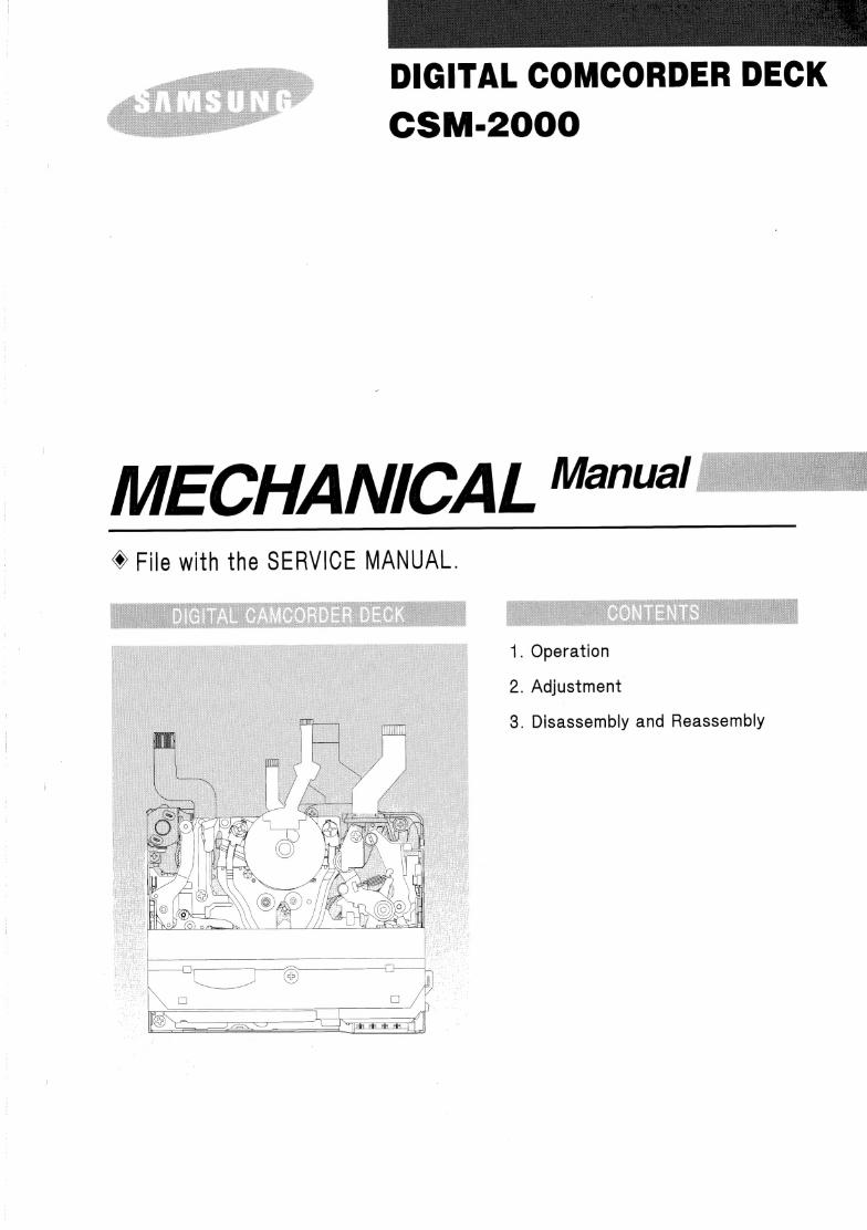
1-1 Nomenclature
THHIHUIIH
= IN | | - Wt
2 @
3 @ , ®
- @
® 6 ©
7 ® 8 ) Sas ©
© 10 20)
@
Fig ti
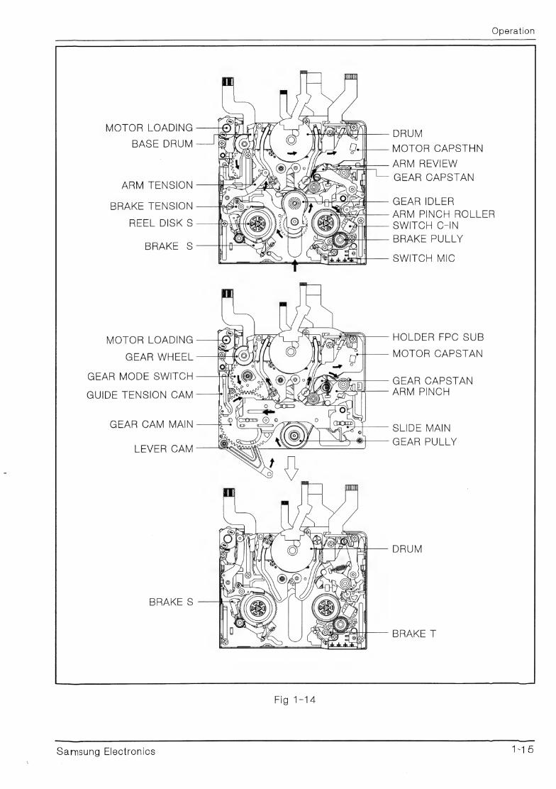
@ BASE DRUM @ BRAKE S @® ARM PINCH
@ MOTOR LOADING @ REEL DISK S @ COVER REEL
~® GEAR WHEEL @ IDLER @ LEVER EJECT
@ GEAR MODE SWITCH @ HOLDER FPC SUB @® REEL DISK T
@ GUIDE TENSION CAM @ DRUM | @ BRAKE PULLY
@ ARM TENSION @® MOTOR CAPSTAN @ SWITCH MIC
@ BRAKE TENSION @ REVIEW ARM @ BRAKE MAIN T
Samsung Electronics (Faat
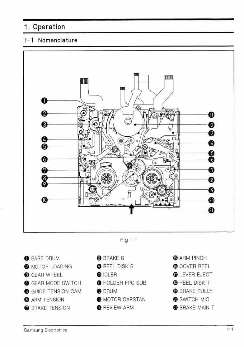
9o od 9Oe © D
@ BASE DRUM
@ MOTOR LOADING
® GEAR WHEEL
@ GEAR MODE SWITCH
@ GUIDE TENSION CAM
© POLE BASE S
@ SLIDE MAIN
@ GEAR CAM MAIN
@ LEVER CAM
venenroes
hese | Kp
= / Xp EO) (OY TSE AEE TEA T
Fig 1-2
@ DRUM
@ HOLDER FPC SUB
@ MOTOR CAPSTAN
® GUIDE RAIL
@ GEAR CAPSTAN
® ARM PINCH
@ POLE BASE T
@ TIMMING BELT
@ GEAR PULLY
9S 6 ©6698 66
Samsung Electt nics
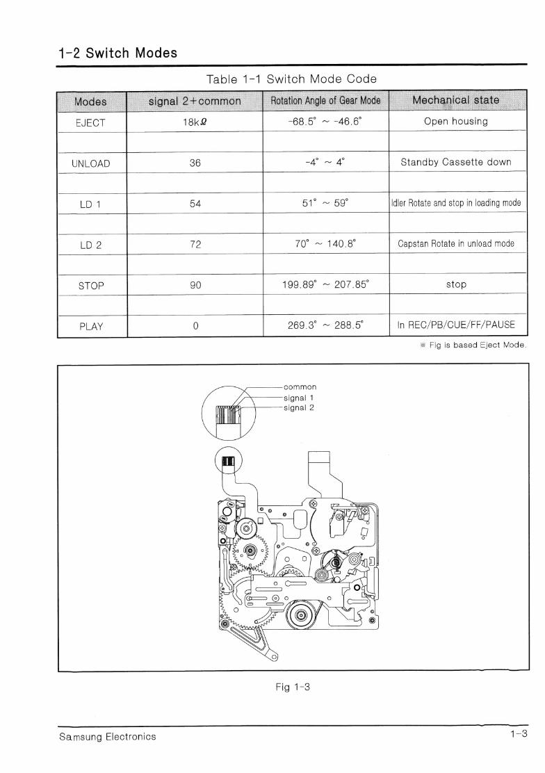
1-2 Switch Modes NN
Table 1-1 Switch Mode Code
EJECT =00:0 = =40-0 Open housing
51° ~ 59° Idler Rotate and stop in loading mode
70° ~ 140.8 Capstan Rotate in unload mode
LD
LZ
199.89° ~ 207.85 stop
2600.6 -~ 288.5 In REC/PB/CUE/FF/PAUSE
* Fig is based Eject Mode.
common
signal 1
signal 2
Samsung Electronics 420
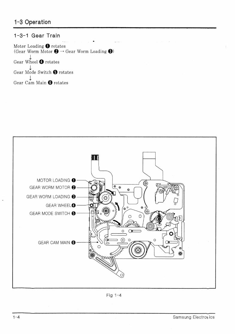
1-3 Operation
1-3-1 Gear Train
Moter Loading @ rotates (Gear Worm Motor @ — Gear Worm Loading @)
i; Gear Wheel @ rotates
ak Gear Mode Switch @ rotates
ub Gear Cam Main @ rotates
MOTOR LOADING @
GEAR WORM MOTOR @
GEAR WORM LOADING @
GEAR WHEEL@
GEAR MODE SWITCH @
GEAR CAM MAIN @
Fig 1-4
ee | | - Samsung Electronics
Operation
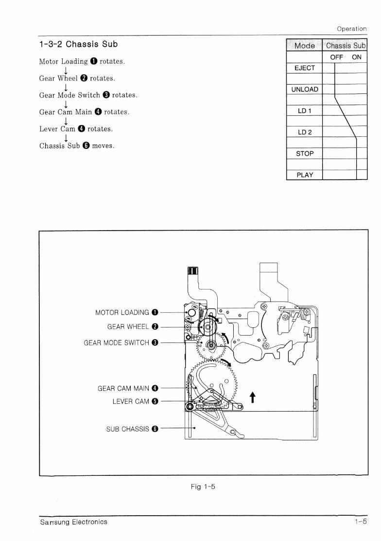
1-3-2 Chassis Sub
Motor Loading @ rotates.
i Gear Wheel @ rotates.
1 Gear Mode Switch @ rotates.
i Gear Cam Main @ rotates.
Lever Cam @ rotates.
[ Chassis Sub @ moves.
MOTOR LOADING @
GEAR WHEEL @
GEAR MODE SWITCH @
GEAR CAM MAIN @
LEVER CAM @
SUB CHASSIS @
Samsung Electronics 1-5
Operation
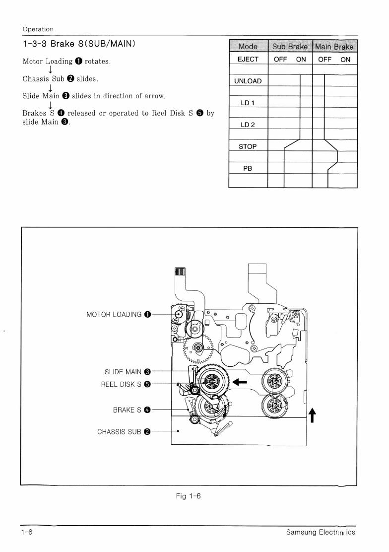
1-8-3 Brake S(SUB/MAIN)
Motor Loading @ rotates.
ieee @ slides.
Slide Main @ slides in direction of arrow.
1 Brakes S @ released or operated to Reel Disk S @ by slide Main @.
MOTOR LOADING @ /
“QP FSS .
—,
«.
SLIDE MAIN ©
REEL DISK S ©
BRAKE S @
CHASSIS SUB @
Fig. 1=6
ne nN eran a eSSSS SSSSSSSSGEA, SSSSSES
1-6 Samsung Electrin ics
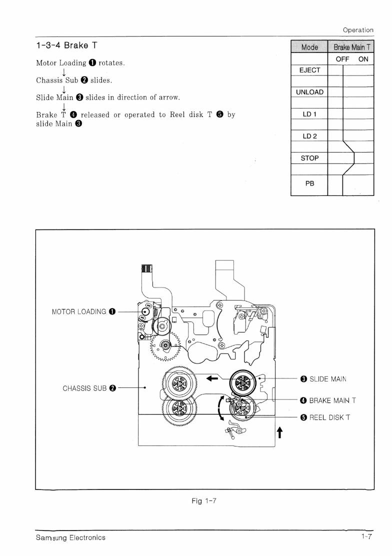
1-3-4 Brake T
Motor Loading @ rotates.
seca ak @ slides.
Slide Main @ slides in direction of arrow.
1 Brake T @ released or operated to Reel disk T @ by slide Main ©
MOTOR LOADING @
CHASSIS SUB @
Fig 1-7
Samsung Electronics
; S cA
ne , ‘f) A) ws ny 7
wy2 ’ NY, | . oy
)))) | Ae 2 OR &
Operation
© SLIDE MAIN
© BRAKE MAIN T
@® REEL DISK T
Operation
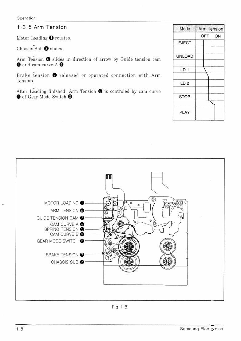
1-3-5 Arm Tension
Motor Loading @ rotates.
fieiacia ie @ slides.
Arm Tension @ slides in direction of arrow by Guide tension cam
@ and cam curve A®
Brake tension @ released or operated connection with Arm
Tension.
After Loading finished, Arm Tension @ is controled by cam curve © of Gear Mode Switch @.
MOTOR LOADING @
ARM TENSION @
GUIDE TENSION CAM @
CAM CURVE A @ SPRING TENSION @
CAM CURVE B @
GEAR MODE SWITCH @
BRAKE TENSION @
CHASSIS SUB @
Fig 1-8
176 Samsung Electonics
Operation
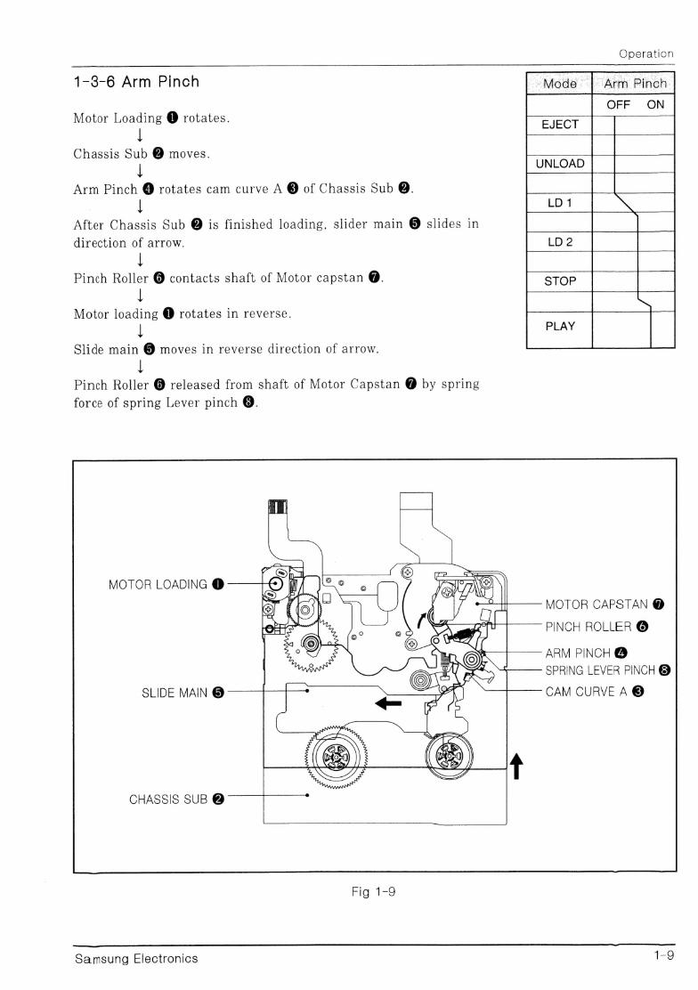
1-3-6 Arm Pinch
Motor Loading @ rotates.
{ Chassis Sub @ moves.
| Arm Pinch @ rotates cam curve A @ of Chassis Sub @.
| { After Chassis Sub @ is finished loading, slider main @ slides in
direction of arrow.
{ Pinch Roller @ contacts shaft of Motor capstan @.
t Motor loading @ rotates in reverse.
{ Slide main @ moves in reverse direction of arrow.
Pinch Roller @ released from shaft of Motor Capstan @ by spring
force of spring Lever pinch ®.
MOTOR LOADING @
SLIDE MAIN @
CHASSIS SUB @
Fig 1-9
MOTOR CAPSTAN @
PINCH ROLLER @
ARM PINCH @
SPRING LEVER PINCH @
CAM CURVE A @
Lee ee eee ener eee rer ere n en rne ereaaaereeeaee ——————N
Samsung Electronics ee,
Operation
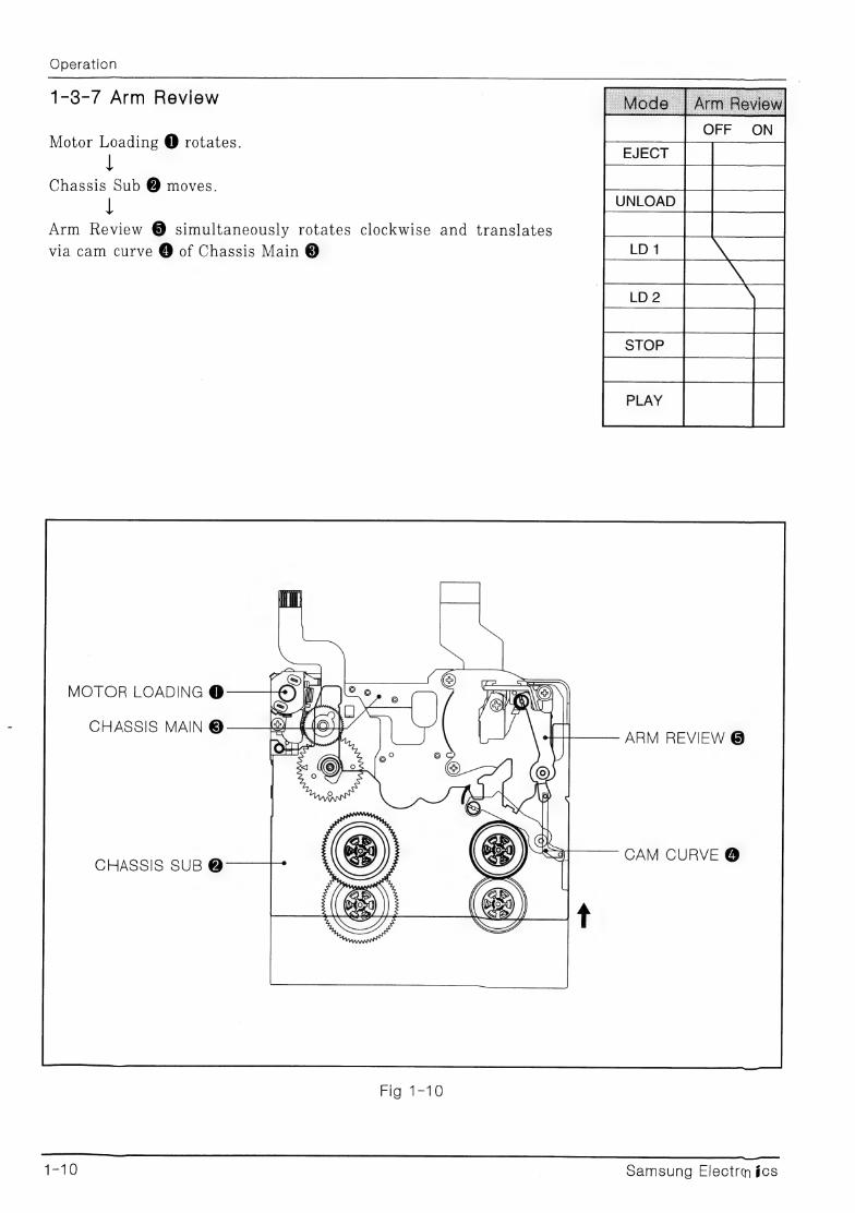
1-8-7 Arm Review
Motor Loading @ rotates.
t Chassis Sub @ moves.
1 Arm Review ® simultaneously rotates clockwise and translates
via cam curve @ of Chassis Main @
MOTOR LOADING @
CHASSIS MAIN @ PR ARM REVIEW @
CAM CURVE @ CHASSIS SUB @
Fid-l=10
A Sg SUS
1-10 samsung Electrm ics
Operation
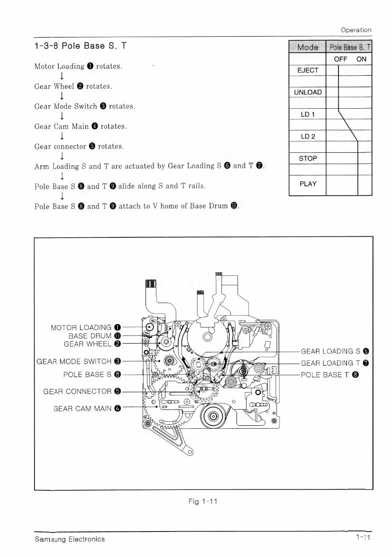
1-3-8 Pole Base S, T
Motor Loading @ rotates.
Gear Wheel @ rotates.
1 Gear Mode Switch ® rotates.
{ Gear Cam Main @ rotates.
{ Gear connector @ rotates.
' Arm Loading S and T are actuated by Gear Loading S @ and T @.
{ Pole Base S @ and T @ slide along S and T rails.
i Pole Base S @ and T @ attach to V home of Base Drum @.
MOTOR LOADING @ BASE DRUM @
GEAR WHEEL @ one as g
GEAR MODE SWITCH @ one % ox oS OX tg TBpl te Sl Ae eae POLE BASE S ® ALS a
Pde vases 4 x
> GEAR CONNECTOR @
GEAR CAM MAIN @
Fig) ta
Samsung Electronics
GEAR LOADING S @
GEAR LOADING T @
POLE BASE T ®
Operation
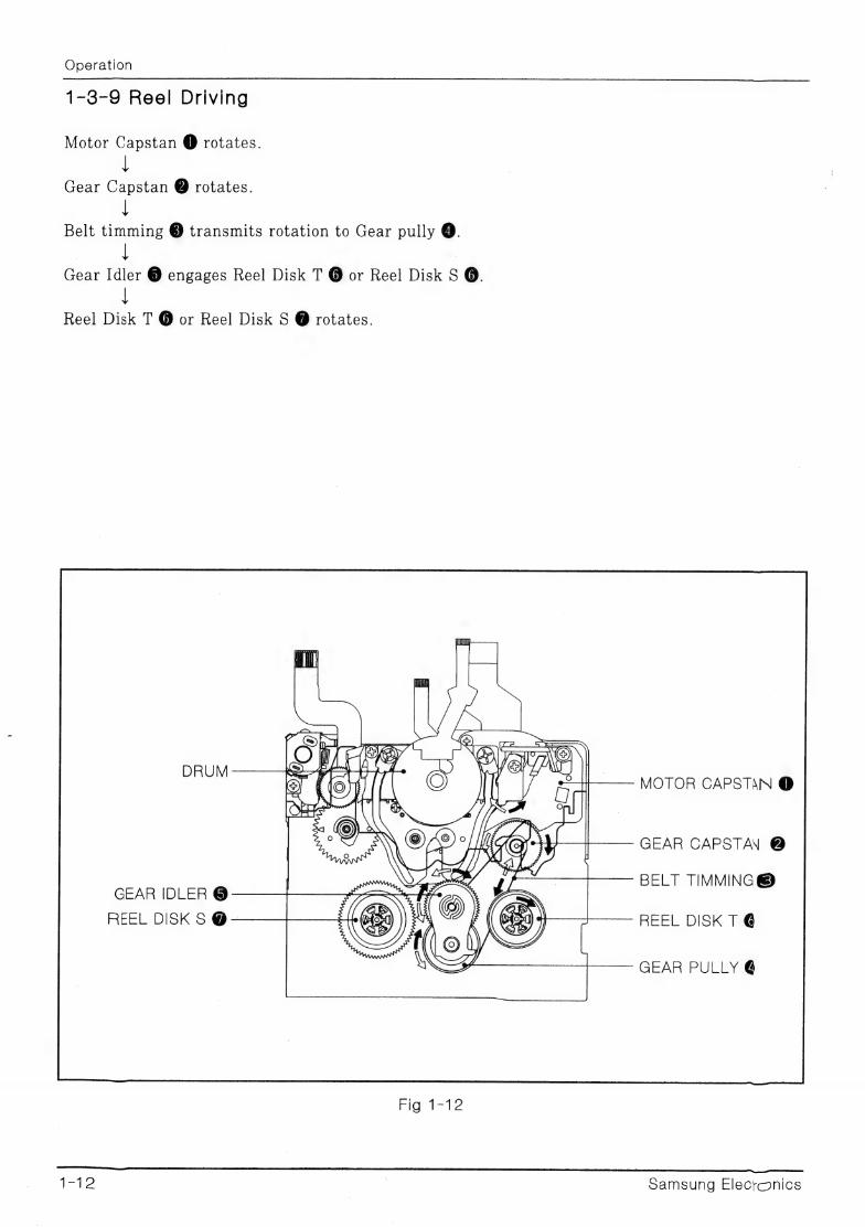
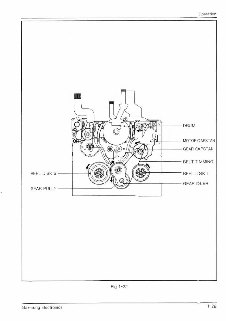
1-3-9 Reel Driving
Motor Capstan @ rotates.
Gear Capstan @ rotates.
Belt timming © transmits rotation to Gear pully @.
| { | Gear Idler @ engages Reel Disk T @ or Reel Disk S @.
{ Reel Disk T @ or Reel Disk S @ rotates.
DRUM MOTOR CAPSTAN @
GEAR CAPSTAN @
BELT TIMMING® GEAR IDLER @
REEL DISK S @- REEL DISK T @
GEAR PULLY @
Fig 112
12 | Samsung Elecronics
1-4 Mode Transitions
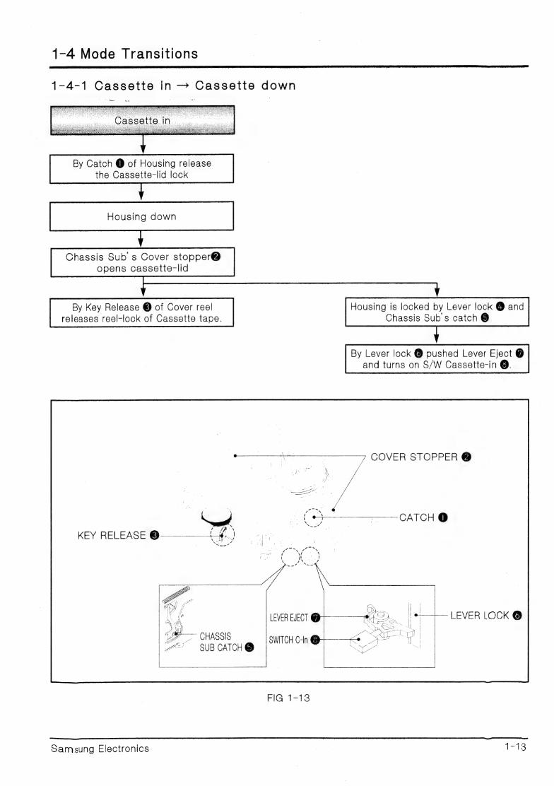
1-4-1 Cassette in — Cassette down
By Catch @ of Housing release the Cassette-lid lock
Chassis Sub s Cover stopper@ opens cassette-lid
By Key Release @ of Cover reel releases reel-lock of Cassette tape.
Housing is locked by Lever lock @ and Chassis Sub s catch @
By Lever lock @ pushed Lever Eject @ and turns on S/W Cassette-in @.
COVER STOPPER @
KEY RELEASE @
LEVER EJECT ¢ the 5. fe LEVER LOCK @
pe SO SWITCH C-In @ SUB CATCH @ ii
FIG 1-13
Samsung Electronics | ee!
Operation
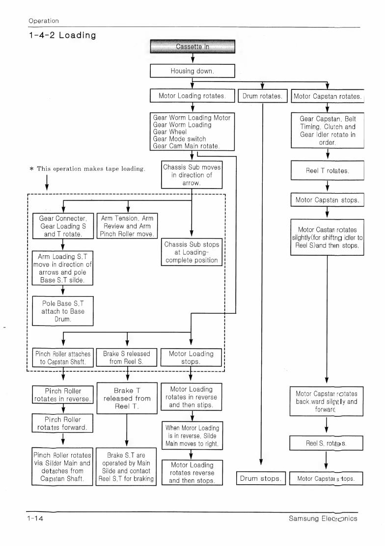
1-4-2 Loading
Motor Loading rotates.
| Gear Worm Loading Motor Gear Worm Loading Gear Wheel Gear Mode switch Gear Cam Main rotate.
Chassis Sub moves
in direction of
arrow.
* This operation makes tape loading.
Arm Tension, Arm
Review and Arm
Pinch Roller move.
Gear Connecter,
Gear Loading S and | rotate.
Chassis Sub stops at Loading-
complete position Arm Loading S,T
move in direction of arrows and pole Base §,T silde.
Pole Base S, 1
attach to Base
Drum.
Pinch Roller attaches |} Brake S released Motor Loading to Capstan Shaft. from Reel S. stops.
— Pinch Roller rotates in reverse.
Pinch Roller rotates forward.
Y Pinch Roller rotates
via Silder Main and
De ig eg, De ge ee Les ee ge ee RT Be og hen ae ee eg ea Rn es ce ce ecm cm sr cc el os es a ce ss ae oe eee ee eee em ee
Motor Loading rotates In reverse
and then stips.
Brake T
released from
Reel |.
When Moror Loading is in reverse, Silde
Main moves to right.
Brake S,T are
operated by Main Motor Loading
rotates reverse
and then stops.
Silde and contact Reel S,T for braking
detaches from Capstan Shaft.
Motor Capstan rotates.
Gear Capstan, Belt
Timing, Clutch and Gear Idler rotate in
order.
Y Reel T rotates.
| Motor Capstan stops.
Motor Castan rotates
silghtly(for shifting idler to Reel S)and then stops.
Motor Capstan rotates back.ward silntly and
forward
Reel S, rotites.
Motor Capstans tops.
Samsung Elecronics
Operation
MOTOR LOADING
BASE DRUM DRUM
MOTOR CAPSTHN
ARM REVIEW
ARM TENSION GEAR CAPSTAN
GEAR IDLER
ARM PINCH ROLLER SWITCH C-IN
BRAKE PULLY
SWITCH MIC
BRAKE TENSION
REEL DISK S
BRAKE S$
AQOLUER-ErS 2Ub
MOTOR CAPSTAN
MOTOR LOADING
GEAR WHEEL
GEAR MODE SWITCH
GUIDE TENSION CAM
GEAR CAPSTAN ARM PINCH
GEAR CAM MAIN SLIDE MAIN
GEAR PULLY LEVER CAM
DRUM
BRAKE S
BRAKE T
rig. t=14
Samsung Electronics 1-15
Operation
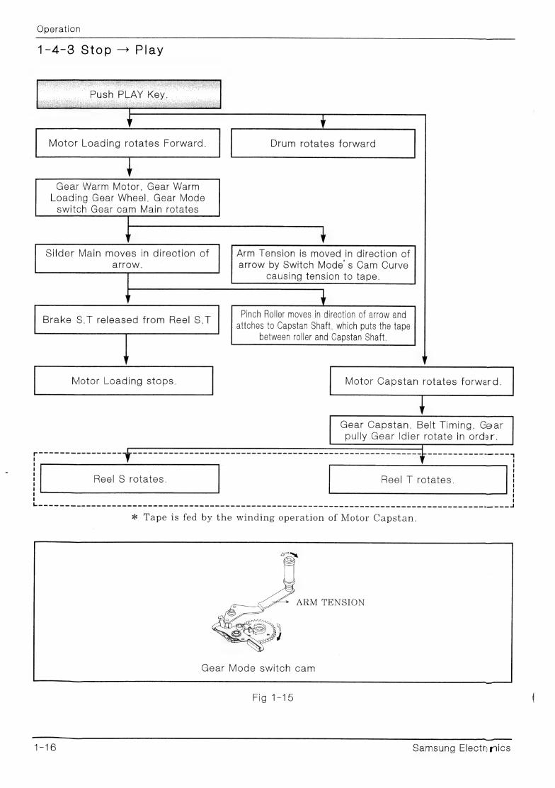
1-4-3 Stop — Play
Motor Loading rotates Forward. Drum rotates forward
Gear Warm Motor, Gear Warm
Loading Gear Wheel, Gear Mode switch Gear cam Main rotates
Silder Main moves in direction of
arrow.
Brake S.T released from Reel S,T
Motor Loading stops.
Arm Tension is moved in direction of arrow by Switch Mode s Cam Curve
causing tension to tape.
Pinch Roller moves in direction of arrow and atiches to Capstan Shaft. which puts the tape
between roller and Capstan Shaft.
Motor Capstan rotates forward.
Gear Capstan, Belt Timing, Gear pully Gear Idier rotate in order.
Reel S rotates. Reel T rotates.
——— a ee ee ee ee ee ee ee ee ey ee ee ee ee ee ee ee ee ee ee ee ee ee ee ee ee me ees cy ee eee ee eee ce ess ee ee ee ee es eee ee eee ee ee es ee SG SE ee ee ee ee a ee LAS
ARM TENSION
Gear Mode switch cam
AiG. 1216
1S Samsung Electn mics
Operation
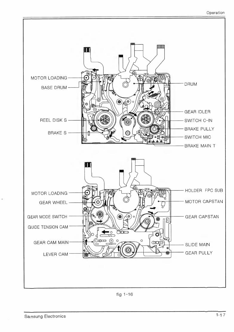
MOTOR LOADING
BASE DRUM
REEL DISK S
BRAKE S
MOTOR LOADING
GEAR WHEEL
GEAR MODE SWITCH
GUIDE TENSION CAM
GEAR CAM MAIN
LEVER CAM
Samsung Electronics
DRUM
GEAR IDLER
SWITCH C-IN
BRAKE PULLY
SWITCH MIC
BRAKE MAIN T
HOLDER FPC SUB
MOTOR CAPSTAN
GEAR CAPSTAN
SLIDE MAIN
GEAR PULLY
Operation
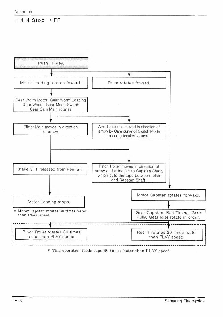
1-4-4 Stop > FF
Push FF Key.
Motor Loading rotates foward. Drum rotates foward.
Gear Worm Motor, Gear Worm Loading Gear Wheel, Gear Mode Switch
Gear Cam Main rotates
Slider Main moves in direction Arm Tension is moved in direction of
of arrow arrow by Cam curve of Switch Mode
causing tension to tape.
Pinch Roller moves in direction of arrow and attaches to Capstan Shaft, which puts the tape between roller
and Capstan Shaft.
Motor Capstan rotates forward. |
Brake S, T released from Reel S,T
Motor Loading stops.
* Motor Capstan rotates 30 times faster 2. imi f than PLAY speed. Gear Capstan, Belt Timing. Ga
Pully, Gear Idler rotate in order.
oe oe eee ee ee ee ee ee ee ee SS Se Se ED NS SD SS SD ee Ce GS SD Ge SD SED Ge Oe ee Ee SE Ge SD GED SED Gy GE ET GD GP SES ED Ge ce ew CUS Ome! com Oe es EE OS Ge ome CP ED eS OE Gee ee Oe ee ee OS So ee
Pinch Roller rotates 30 times Reel T rotates 380 times faster | faster tnan PLAY speed. | — tnan PLAY speed.
— NS Sm cS EU ES SS SE ST SS GS SSS Ga a ee ee mS CGS Ce eS Se eC Gee Se GSE GR SP SO OL GS Ge eS en OD eT Oe SS US eS SS SD GU GES SD OU eS nD ome one os mA, om om ae
* This operation feeds tape 30 times faster than PLAY speed.
PoSSsSS=-S5 rene anne
1-18 Samsung Electnmics
Operation
MOTOR LOADING
BASE DRUM re
GEAR-IDLER
REEL DISKS SWITCH C-IN
aes BRAKE PULLY
SWITCH MIC
BRAKE MAIN T
MOTOR LOADING RM onrsees ea ret
GEAR WHEEL MOTOR CAPSTAN
GEAR MODE SWITCH GEAR CAPSTAN
GUIDE TENSION CAM
GEAR CAM MAIN SLIDE MAIN
GEAR PULEY LEVER CAM
ie a
Samsung Electronics 1-19
Operation
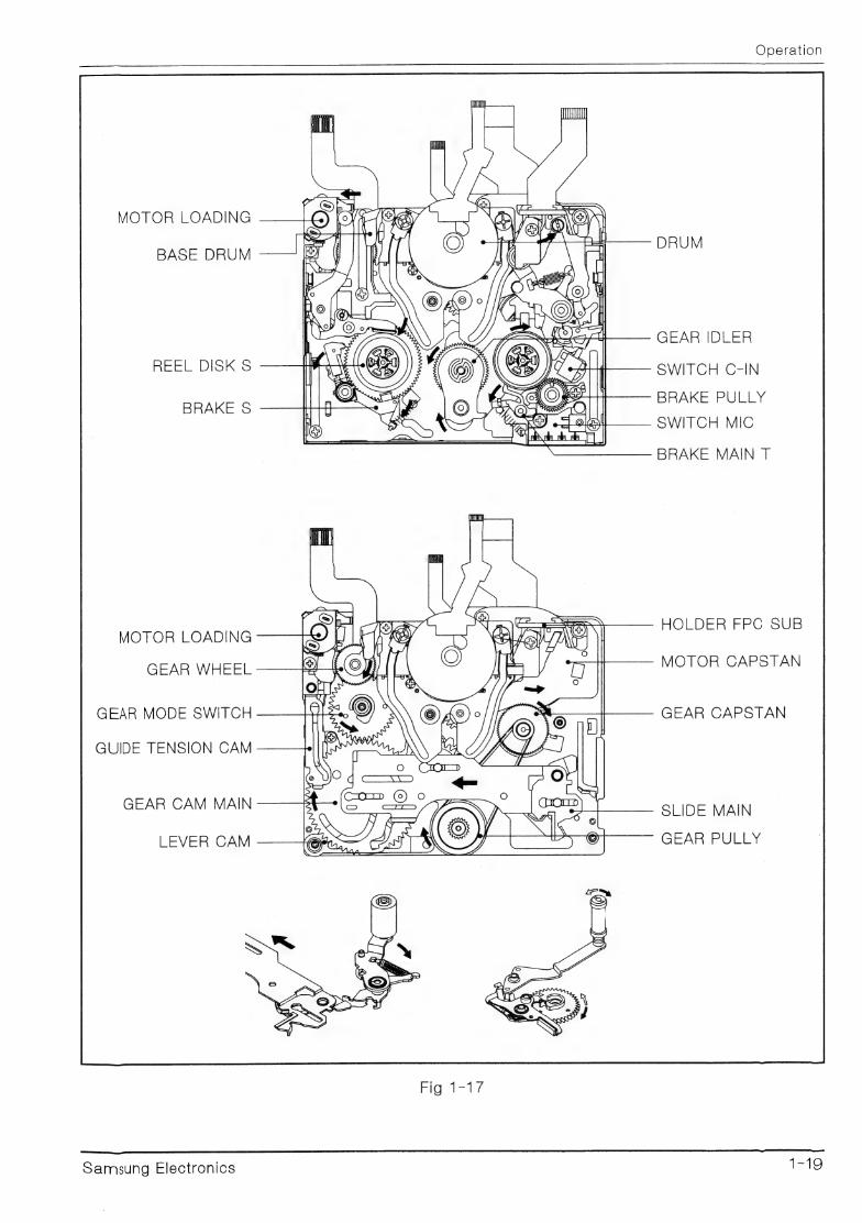
1-4-5 Stop — REW
Motor Loading rotates forward.
Gear Worm Motor Gear Worm Loading Gear Wheel, Gear Mode Switch
Gear Cam Main rotate.
Silder Main moves in
direction of arrow.
Brake S released
from Reel S.,
Motor Loading stops.
Motor Capstan rotates reverse.
Gear Capstan, Belt Timming, Gear pully and Gear Idler rotate in order.
Reel totates 30
times faster than
PLAY speed.
Reel S rotates 30
times faster than
PLAY speed. —
ee ae |
* This operation feeds tape 30 times faster than PLAY mode.
Arm Tension is moved in direction of arrow by switch cam of gear mode causing tension to tape
Pinch Roller moves in direction of arrow and attaches to
Capstan Shaft. which puts the tape between roller and
capstan shaft.
Drum rotates forward
* Motor Capstan rotates about 30 times faster than PLAY mode.
Samsung Electonics
Operation
HUI
ay OOUOLOORE
@ =. _—
MOTOR LOADING \al aro ae sh ny BASE DRUM Md Ve \
J) Saaes) \ [SE (ot
, "I ey Be | mo
\ fo GEAR IDLER
REEL DISK S SWITCH C-IN BRAKE PULLY
BRAKE S SWITCH MIC
— BRAKE MAIN T
GEAR WHEEL MOTOR CAPSTAN
GEAR MODE SWITCH GEAR CAPSTAN
GUIDE TENSION
GEAR CAM MAIN SLIDE MAIN
LEVER CAM GEAR PULLY
Fig: JG
Samsung Electronics 7 12d
Operation
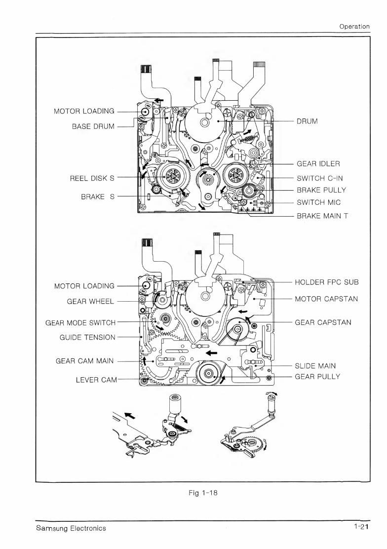
1-4-6 Stop — REC
Motor Loading rotates forward. Drum rotates forward.
Gear Worm Motor, Gear Worm
Loading Gear Wheel, Gear Mode switch, Gear Cam Main rotate.
Silder Main moves in direction Arm Tension is moved in direction of arrow. arrow by Cam of Switch Mode.
Brake S, T released from
Reel S, T
! t ‘ 1
Pinch Roller moves in direction of arrow
and attaches to Capstan Shaft
Motor Capstan rotates in | reverse. Motor Loading stops.
Gear Capstan, Belt Timing. Gear | Pully, and Gear Idler rotate in order. penis
r —— a ae See ee See See ce ane cee Fe ces ees ee ee eee ee ee ee ee ee ee ee ee eee ee ee ee ee ee ee ee ee eee ee ee ee ee ee ee eee ce eee ee eee es ee ee esse ee es ee ye
Reel | rotates. Reel S rotates.
Cee =. bo eo oe
Motor Capstan stops.
Reel T stops. Reel S stops.
* Drum is rotating during REC/PAUSE
Motor Capstan rotates forward. Pinch Roller rotates.
Reel T rotates.
* ‘Tape is wound to Reel T by this operation.
1-22 Samsung Electo nics

Operation
MOTOR LOADING
L@ (2S Aare | 4 ao DRUM
BASE DRUM hn | £// Same) \ tp [oe <c : phd a a GEAR IDLER ag 5a |
REEL DISK S 2) Sal _
S| BRAKE S af) || oo aie SWITCH MIC
= BRAKE MAIN T
MOTOR LOADING HOLDER FPG * sue
GEAR WHEEL MOTOR CAPSTAN
GEAR MODE SWITCH GEAR CAPSTAN
GUIDE TENSION CAM
GEAR CAM MAIN SLIDE MAIN
LEVER CAM GEAR PULLY
Fig 1-19
Samsung Electronics 123
Operation
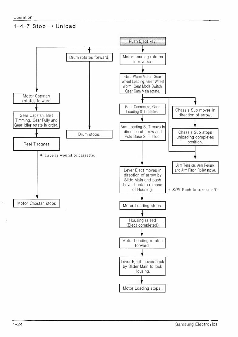
1-4-7 Stop — Unload
Drum rotates forward. Motor Loading rotates in reverse.
Gear Worm Motor, Gear
Wheel Loading, Gear Wheel Worm, Gear Mode Switch, Gear Cam Main rotate.
Gear Connector, Gear Loading S,T rotates.
Arm Loading S, T move in direction of arrow and
rum Stops. Pole Base S, T silde.
Motor Capstan rotates forward.
Gear Capstan, Belt Timming, Gear Pully and
Gear Idler rotate in order.
Reel T rotates
* Tape is wound to cassette.
Chassis Sub moves in
direction of arrow.
Chassis Sub stops unloading completes
position.
Arm Tension, Arm Review
and Arm Pinch Roller move.
* S/W Push is turned off.
Lever Eject moves in direction of arrow by Silde Main and push Lever Lock to release
of Housing.
Motor Loading stops.
Housing raised
(Eject completed)
Motor Loading rotates forward.
Y Lever Eject moves back
by Slider Main to lock
Motor Capstan stops
Housing.
Motor Loading stops.
1-24 Samsung Electra ics
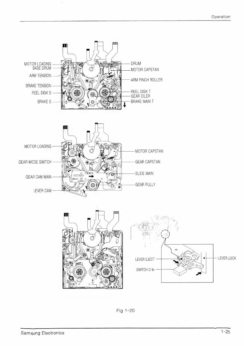
Operation
MOTOR LOADING DRUM BASE DRUM MOTOR CAPSTAN
ARM TENSION ARM PINCH ROLLER
BRAKE TENSION BEY ed
REEL DISK § “, ( @B)\ 4251 — REEL DISK T ANS Ay || GEAR IDLER
BRAKE $ AO BRAKE MAIN T
MOTOR LOADING MOTOR CAPSTAN
GEAR MODE SWITCH GEAR CAPSTAN
GEAR CAM MAIN SLIDE MAIN
GEAR PULLY
LEVER CAM
eb g O),
om fo Sh
Re JO ea: @ NS [e}
eel lone
C/ 4
LEVER EJECT
SWITCH C-In
Fig 1420
Samsung Electronics 1-25
Operation
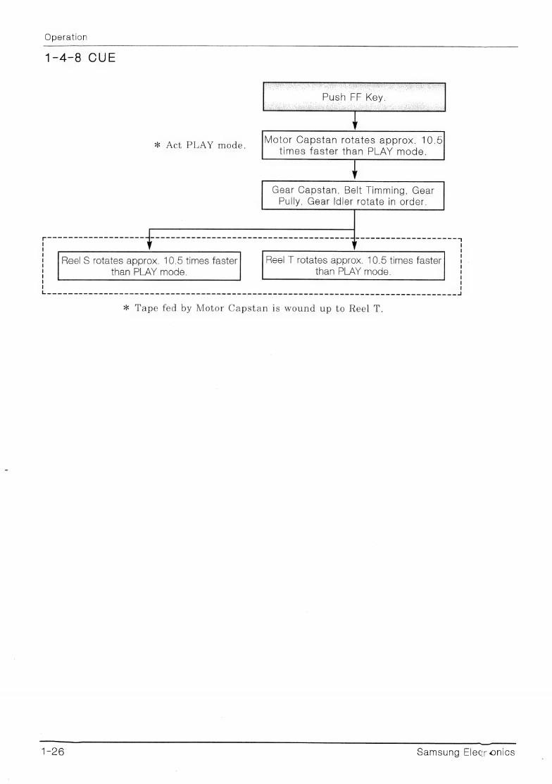
1-4-8 CUE
Reel S rotates approx. 10.5 times faster Reel T rotates approx. 10.5 times faster than PLAY mode. than PLAY mode.
* Tape fed by Motor Capstan is wound up to Reel T.
le ee
LL SS SSeS sts
1-26 samsung Elecr onics

REE DISK oS
GEAR CLUTCH
Frids tc)
Samsung Electronics
Operation
DRUM
MOTOR CAPSTAN
GEAR CAPSTAN
BELT TIMMING
REEL DISK T
GEAR ADEE
ea
Operation
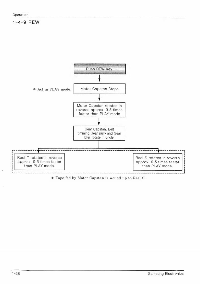
1-4-9 REW
* Act in PLAY mode. Motor Capstan Stops
Motor Capstan rotates in reverse approx. 9.5 times faster than PLAY mode
Gear Capstan, Belt timming,Gear pully and Gear
Idler rotate in oncler
Reel S rotates in reverse
approx. 9.5 times faster tnan PLAY mode.
Reel T rotates in reverse
approx. 9.5 times faster than PLAY mode.
ia as aes alae | Ls ee eel
* Tape fed by Motor Capstan is wound up to Reel S.
Le EP SSS SSS SSS SSS Shs ss ens SSNS
1-28 Samsung Electrics
Operation
DRUM
MOTOR CAPSTAN
GEAR CAPSTAN
BELT TIMMING
REEL DISK S REEL DISK T
GEAR ID CER GEAR PULLY
FIG: l=22
Samsung Electronics 1-29

1=30 Samsung Electionics
2. Adjustment
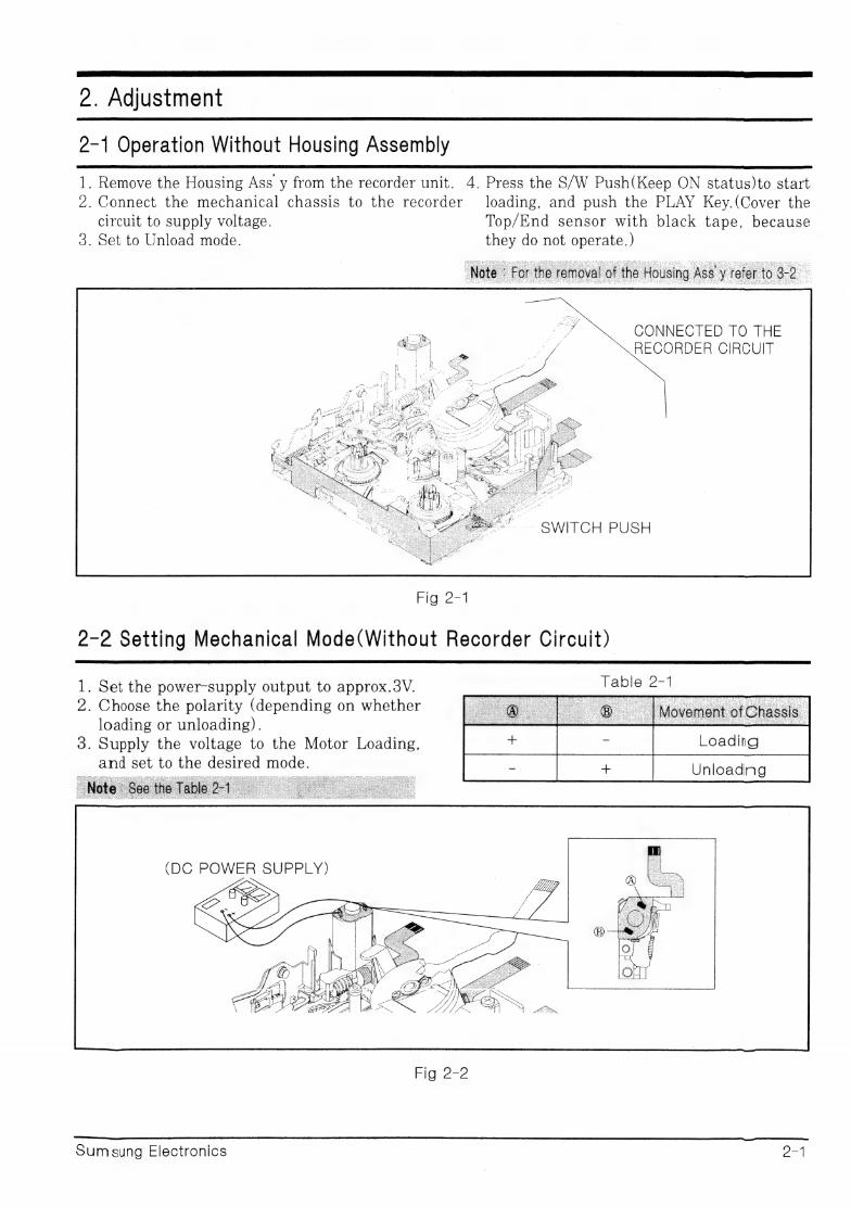
2-1 Operation Without Housing Assembly
1. Remove the Housing Ass y from the recorder unit. 4. Press the S/W Push(Keep ON status)to start 2. Connect the mechanical chassis to the recorder loading, and push the PLAY Key.(Cover the
circuit to supply voltage. Top/End sensor with black tape, because 3. Set to Unload mode. they do not operate.)
CONNECTED TO THE RECORDER CIRCUIT
SWITCH PUSH
Fig 2-1
2-2 Setting Mechanical Mode(Without Recorder Circuit)
1. Set the power-supply output to approx.38V. | ee Re ‘ease
loading or unloading). : 3. Supply the voltage to the Motor Loading,
and set to the desired mode. Unloadng
(DC POWER SUPPLY) Ulf
Sumsung Electronics aa
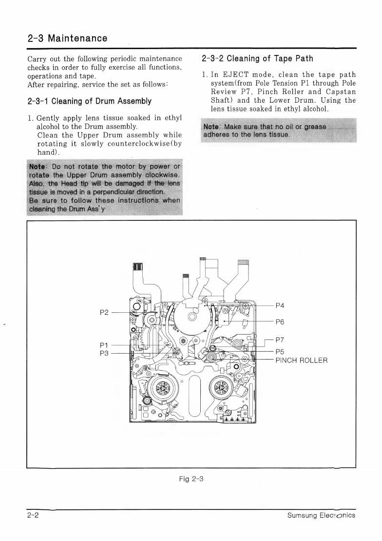
2-3 Maintenance
Carry out the following periodic maintenance 2-3-2 Cleaning of Tape Path checks in order to fully exercise all functions, operations and tape. 1. In EJECT mode, clean the tape path
After repairing, service the set as follows: system(from Pole Tension Pl through Pole Review P7, Pinch Roller and Capstan
2-3-1 Cleaning of Drum Assembly Shaft) and the Lower Drum. Using the lens tissue soaked in ethyl alcohol.
1. Gently apply lens tissue soaked in ethyl
alcohol to the Drum assembly. Clean the Upper Drum assembly while rotating it slowly counterclockwise(by
hand).
PA (ee jerry Y P6
=
|| mes P/
Alcoa pA PS PINCH ROLLER
la 8 "
if
FIG.2-3
2-2 Sumsung Electonics
Adjustment se a SS SSS SSS SS
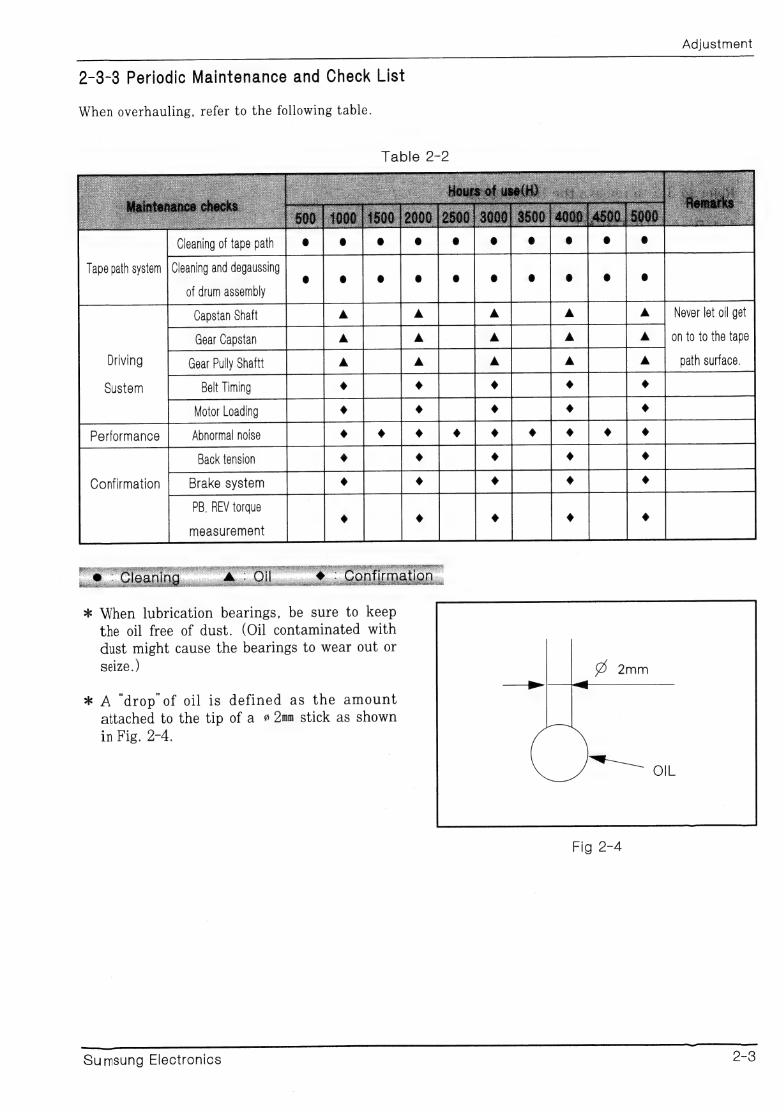
9-3-3 Periodic Maintenance and Check List
When overhauling, refer to the following table.
Tape path system
Never let oil get Capstan Shaft ba
tear cpan | on to to the tape
Driving path surface.
Sustem
Performance
Brake system
PB, REV torque
measurement
Confirmation
* When lubrication bearings, be sure to keep
the oil free of dust. (Oil contaminated with
dust might cause the bearings to wear out or
seize. )
* A “drop of oil is defined as the amount attached to the tip of a # 2mm stick as shown
in Fig. 2-4.
Fig 2-4
Sumsung Electronics o-3
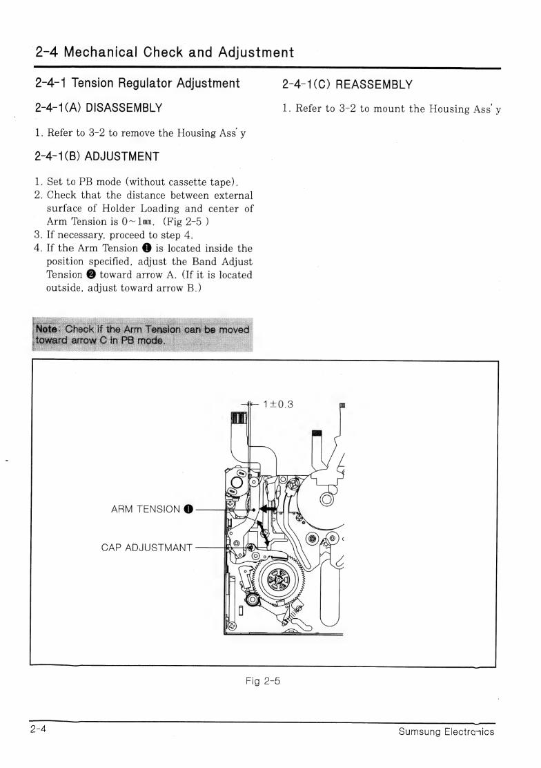
2-4 Mechanical Check and Adjustment
2-4-1 Tension Regulator Adjustment 2-4-1(C) REASSEMBLY
2-4-1(A) DISASSEMBLY 1. Refer to 3-2 to mount the Housing Ass’ y
L Refer to 3-2 to remove the Housing Ass y
2-4-1(B) ADJUSTMENT
1. Set to PB mode (without cassette tape). 2. Check that the distance between external
surface of Holder Loading and center of
Arm Tension is 0O~1mm, (Fig 2-5 ) 3. If necessary, proceed to step 4.
4. If the Arm Tension @ is located inside the
position specified, adjust the Band Adjust
Tension @ toward arrow A. (If it is located
outside, adjust toward arrow B.)
ARM TENSION @
CAP ADJUSTMANT
FIGwZ=o
2-4 | Sumsung Electronics
2-4-2 Back Tension Confirmation
1. Set up the cassette-torque tape.
2.Set to CAMERA mode, push the
EDIT(+) KEY and check that the
torque value of Reel S is 4.5+0.5g.cm.
2-4-3 PB/REV Torque check
1. Set up the cassette torque tape.
2.Set to CAMERA mode, Push the
EDIT(+)Key and check that the torque
value of Reel T is 7.5+3g.cm.
3. Push the EDIT(-) Key and check that
the torque value of Reel S is 12.5+
3g.cm.
4. If necessary, replace the defective Gear
pully Ass y.
Adjustment
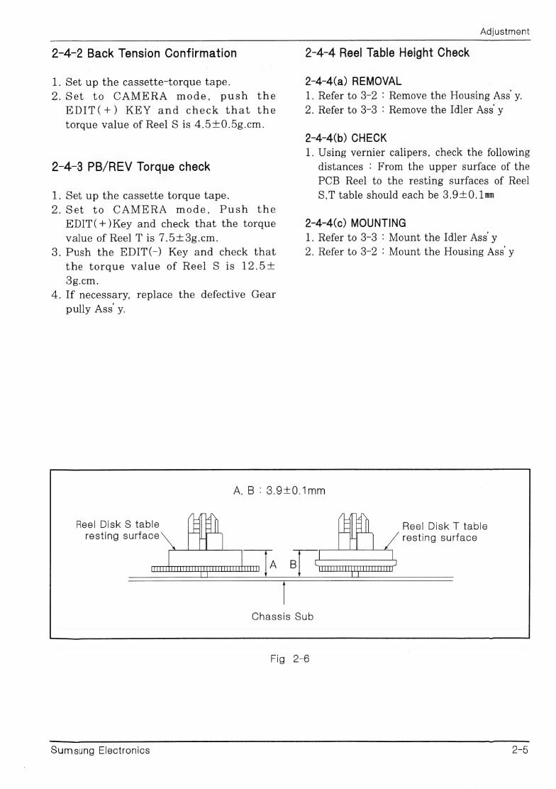
2-4-4 Reel Table Height Check
2-4-4(a) REMOVAL | 1. Refer to 3-2 : Remove the Housing Ass y.
2. Refer to 3-3 : Remove the Idler Ass y
2-4-4(b) CHECK
1. Using vernier calipers, check the following
distances : From the upper surface of the
PCB Reel to the resting surfaces of Reel
S,T table should each be 3.90. 1mm
2-4-4(c) MOUNTING 1. Refer to 3-3 : Mount the Idler Ass y 2. Refer to 3-2 : Mount the Housing Ass y
A,B: 3.940.1mm
Reel Disk S table resting surface
Reel Disk T table resting surface
Chassis Sub
Fig 2-6
Sumsung Electronics 25
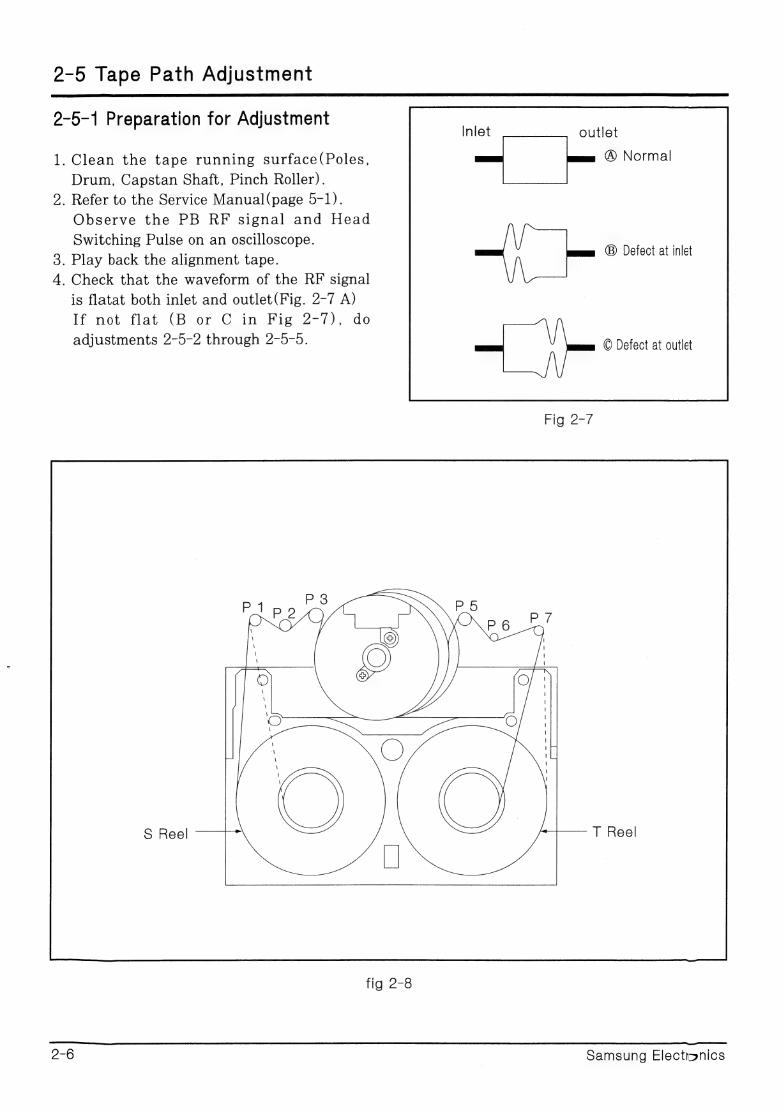
2-5 Tape Path Adjustment
2-5-1 Preparation for Adjustment outlet
1. Clean the tape running surface(Poles, @ Normal
Drum, Capstan Shaft, Pinch Roller).
2. Refer to the Service Manual(page 5-1).
Observe the PB RF signal and Head
Switching Pulse on an oscilloscope.
3. Play back the alignment tape.
4. Check that the waveform of the RF signal
is flatat both inlet and outlet(Fig. 2-7 A) If not flat (B or C in Fig 2-7), do
adjustments 2-5-2 through 2-5-5. EDetocvat cutie
Defect at inlet
Pigi2e-7
S Reel T Reel
fig 2-8
2-6 | Samsung Electonics
Adjustment
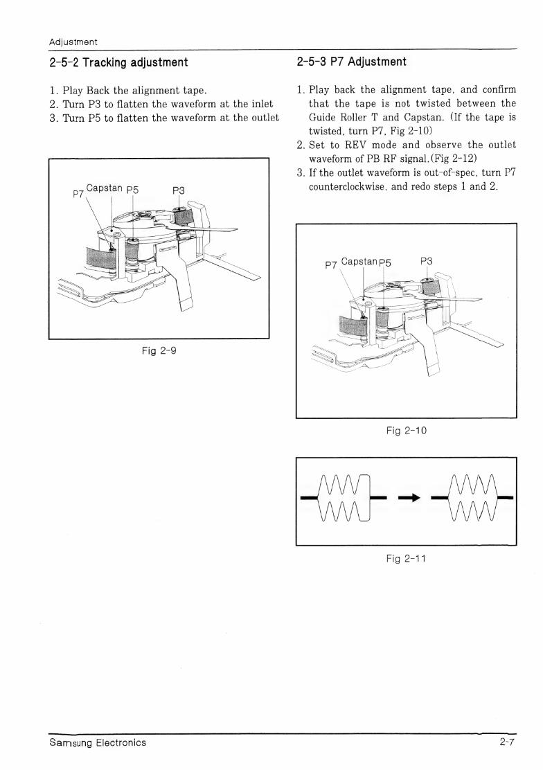
2-5-2 Tracking adjustment 2-5-3 P7 Adjustment
1. Play Back the alignment tape. 1. Play back the alignment tape, and confirm
2. Turn P3 to flatten the waveform at the inlet that the tape is not twisted between the
3. Turn P5 to flatten the waveform at the outlet Guide Roller T and Capstan. (If the tape is
twisted, turn P7, Fig 2-10)
2. Set to REV mode and observe the outlet
waveform of PB RF signal.(Fig 2-12)
3. If the outlet waveform is out-of-spec, turn P7
Capstan p5 counterclockwise, and redo steps | and 2. Pe
Fig 2-9
Fig 2-10
Fig-2=— 1
Samsung Electronics OF
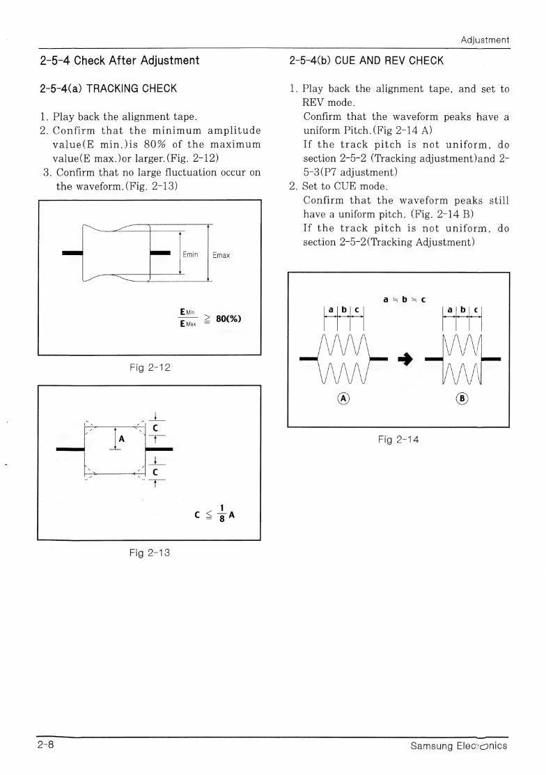
2-5-4 Check After Adjustment
2-5-4(a) TRACKING CHECK
1. Play back the alignment tape.
2. Confirm that the minimum amplitude
value(E min.)is 80% of the maximum
value(E max.)or larger. (Fig. 2-12)
3. Confirm that no large fluctuation occur on
the waveform. (Fig. 2-13)
Emin Emax
Fig 2-12
Fig 2-13
Adjustment
2-5-4(b) CUE AND REV CHECK
1. Play back the alignment tape, and set to
REV mode.
Confirm that the waveform peaks have a
uniform Pitch.(Fig 2-14 A)
If the track pitch is not uniform, do
section 2-5-2 (Tracking adjustment)and 2-
5-3(P7 adjustment)
2. Set to CUE mode.
Confirm that the waveform peaks still
have a uniform pitch. (Fig. 2-14 B)
If the track pitch is not uniform, do
section 2-5-2(Tracking Adjustment)
Fig 2-14
Samsung Elecronics

Adjustment
2-§-5(C) RISE TIME CHECK 2-5-4(D) TAPE PATH CHECK
1. Play back the alignment tape. 1. In CUE and REV modes, check that the
2. Set to playback mode, and confirm that tape is not curled around the Pl, P3, Pd
the waveform of PB RF signal rises flat upper flange and P7 upper/Lower flanges.
within 3 seconds. Also confirm that the
tape is not twisted or curled around the
Pinch Roller. (Fig 2-15)
3. Run the tape in CUE/REV and FF/REW
modes, then playback. Confirm the
waveform of PB RF signal rises flat within
3 seconds. Also confirm that the tape is
not twisted or curled around the Pinch
Roller.
4. Repeat steps 2. and 3.
D7 Capstan p5
Fig 2-15
>
From the S-Reel To the T Reel
FIG.2=16
Samsung Electronics 9-9
3. Disassembly and Reassembly
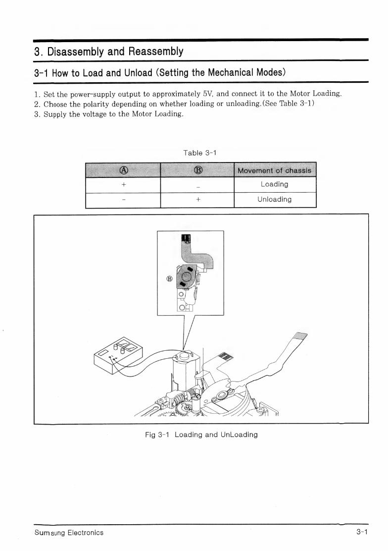
3-1 How to Load and Unload (Setting the Mechanical Modes)
1. Set the power-supply output to approximately 5V, and connect it to the Motor Loading.
2. Choose the polarity depending on whether loading or unloading. (See Table 3-1)
3. Supply the voltage to the Motor Loading.
Table 3-1
Unloading
Fig 8-1 Loading and UnLoading
Oa ea aad
Sum sung Electronics | 2-4

8-2 Housing
3-2-1 Disassembly 3-2-2 Reassembly 1. Mount the Cam L and Cam R of Lever
Housing @ to stud Housing L @ and stud 1. Push the Lever(see arrow, Detail A) turn Housing R@.
the Lever Lock@in the direction of arrow 2. Put the Hook L @ and Hook R into the
B, and open the Housing. Sub chassis @, pushing them in the
2. Remove the screw @ ,and separate the direction of A, and then reassembled
Hook L and Hook R and then lift it. Housing Ass y @ into the Sub chassis @.
3. Separate the Lever L @ and Lever R from 3. Secure the screw @
the Stud-housing L @ and stud-housing R
@, and then lift the Housing Ass y.
HOUSING ASS Y @
LEFT, RIGHT HOOK @
SCREW 1EA @
STUD HOUSING? @
SUB CHASSIS @
FIG 3-2 HOUSING
orc Sumsung Electonics
— WASHER-SLIT @
——\
CaN \4
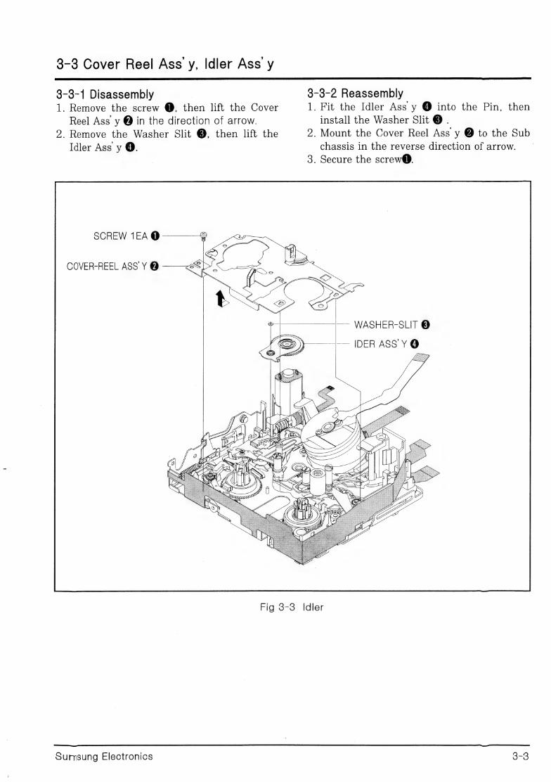
chassis in the reverse direction of arrow.
3. Secure the screw@.
install the Washer Slit @ . 2. Mount the Cover Reel Ass y @ to the Sub
1. Fit the Idler Ass y @ into the Pin, then 3-3-2 Reassembly
4 ALY
i
he
\ ¢
Tw HY VEk(k
emaliis
L Wb *
AX ol - C2
aN
YY
aé Os
g
Nu
NY
pie
:
Reel Ass y @ in the direction of arrow.
SCREW 1EA @
2. Remove the Washer Slit @, then lift the
COVER-REEL ASS Y @
1. Remove the screw @, then lift the Cover
Idler Ass y @.
8-3 Cover Reel Ass y, Idler Ass y
3-3-1 Disassembly
ix
s @
3-3
Fig 38-3 Idler
Sumsung Electronics
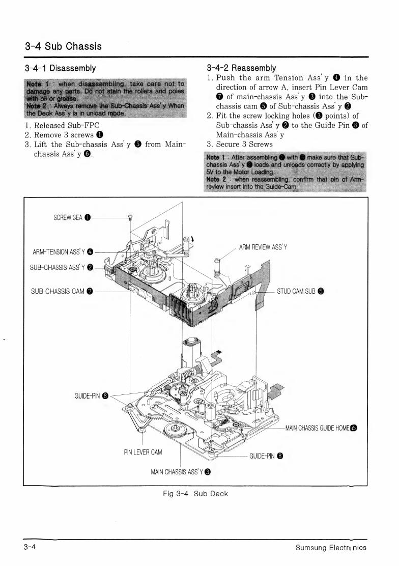
3-4 Sub Chassis
1. Push the arm Tension Ass y ® in the 3-4-2 Reassembly 3-4-1 Disassembly
direction of arrow A, insert Pin Lever Cam
@ of main-chassis Ass y @ into the Sub- chassis cam @ of Sub-chassis Ass y @
ay ‘o)
Gy 5 @
©
os
LLI
To
=
a
=
‘5S
L
Liu
oO
jm)
a
=
= a)
Oo
®
2
Nee
(aa)
PD
mn
&
—
Sp)
cas
=
S
es
oO
=
a
ee.
=
=
oT
A
she.
oD
2
Laas
=
>
oa
LUI
o
2
nM
YO
or
Hm
nN
WZ
2 om
&
=
oe
S
o4G
PY
®
coat
> ae
ee
ee 2S
8
9 om aD)
rns
wn N oD | R= S & e) ft
>
@m)
"wm 6p) << 2
5
8
2
A,
wm
GB
_-
aren)
eS
So
8
S
1
o
P
>—_
>
a
ae
<<
:
:
=
©
OQ
Lu
YD
op)
<
|
“i
cD
cp)
ep)
©
De
ane
=>
<t
<
oO
<
re
EQ
&
ooe0,s,
C5
D
S
op)
SOD
es
a=
=
Sis
Thess
i
ue
O
2e44
=
«a
an =
i
©
>
=]
D
ra
NOY)
-PIN @ GUIDE PIN LEVER CAM
|
MAIN CHASSIS ASS Y @
Fig 3-4 Sub Deck
Sumsung Electro nics 3-4
3-5 Arm-Tension and Arm-Review
3-5-2 Reassembly 1. Insert the Arm Review @ into the pinl @. 2. After Tension Release @ assembled to the
pin 3 @, Brake-Tension @ insert in the
3-5-1 Disassembly pin 3. | | | |
1. Separate the spring-Tension @ from Hook 3. When Arm-Tension @ insert in the pin 2
© of sub-chassis. ©, pin of Arm-Tension @ assembled into
2. Remove the Washer-slit®, and then lift up cam part @ of Brake Tension.
the Arm-Tension @. 4. Assambled the Washer-slit @.
3. Lift up the Brake-Tension @ and the 5. Hang the spring Tension @ to the hook of
Tension Release @. Brake Tension @ and hook of sub-chassis
4. Lift up the Arm-Review®. 0.
SPRING TENSION @
BRAKE TENSION @ CAM PART BRAKE TENSION @
TENSION RELEASE @
WASHER SLIT @ ————®
ARM TENSION PIN @ a
SUB CHASSIS ARM REVIEW @ PIN2@
PIN3 @
SUB CHASSIS @
Fig 3-5 Arm Review and Arm Tension
Sumsung Electronics 3-5
3-6 Reel Disk S, T, Brake S, Brake Main T, Brake Pully, Lever Eject
3-6-1 Disassembly _ 3-6-2 Reassembly 1. Separate the spring Brake S @ from the spring 1. Mount the Lever Eject
hook @, and then lift it up. 2. Remove the washer-slit @, lift up the Brake S @.
3. Separate the spring Main Brake T @ from the
spring hook @, lift up the Brake Main T @ 2. Mount the Brake pully @, secure the screw 4. Lift up the Reel S @, T @. | 1EA ©. 5. Remove the screw 1EA @, lift the Brake pully @. 3. Insert the washer slit @.
6. Lift up the Lever Eject @. 4. Mount the Brake main T @, hang the spring ae Main Brake T @ to the spring hook @.
o. After Mount the Brake S @ and insert the washer slit @, and then hang the spring
Brake S @ to the spring hook @.
ti Abs REEL DISK S @—{W GW) — REEL DISK T @
®———_ SPRING MAIN BRAKE T @ SPRING BRAKE S @ ——* a
WASHER SLIT @ ——¢I “it _—— BRAKE MAIN T @ BRAKES ® e — SCREW 1EA@
BRAKE PULLY @ 5 A 2 <2. LEVER EJECT ©
SPRING HOOK @ SUB CHASSIS STOPPER @
Fig 8-6 RELL DISK S, T, BRAKE S, BRAKE MAIN T, BRAKE PULLY, LEVER EJECT
3-6 Sumsung Electronics
3-7 DRUM
3-7-1 Disassembly 3-7-2 Reassembly 1. Mount and insert the Drum @ to the
Bosses @. 2. Insert the spring plate Drum @, and
secure the screw @.
1. Remove 1 screw @ and then remove the
spring plate Drum @. 2. Remove the Drum @.
DRUM @
HEAD TIP @
BASE DRUM @
2 BOSS ©
Fig 8-7 DRUM
ena arama A CC csc czas a a aee aeanaeacmmmraacnntana ma ee ee ee pe
Sumsung Electronics | Orr
3-8 Guide Rail Ass y
3-8-1 Disassembly
1. Remove the screw 3 @ in the up and the
screw 1 @ in the back, lift up the Guide rail ass y @.
2. Separate it and turn to count clock wise
the Guider Roller S @ and T @, and then separate the spring Guide Roller 2 @.
GUIDE ROLLERS @
SPRING GUIDE ROLLER 2EA @
GUIDE RAIL ASS Y @
POLE BASE S @
MAIN CHASSIS @
3-8-2 Reassembly 1. Insert the Spring Guide Roller 2 @ to the
pole Base S © and T @, and then assemble the Guide Roller S @ and T @ as turn to count clock wise.
2. After Pole Base S @ and T © unloading mode, and then assemble Guide Rail Assy @ to the Main chassis @ and secure the screw
3 @ in the up and the screw 1 in the back @.
GUIDE ROLLER T @
SCREW 3EA @
DRUM BASE ©
POLE BASE T @
Fig 38-8 Guide Rail
3-8 Sumsung Electronics
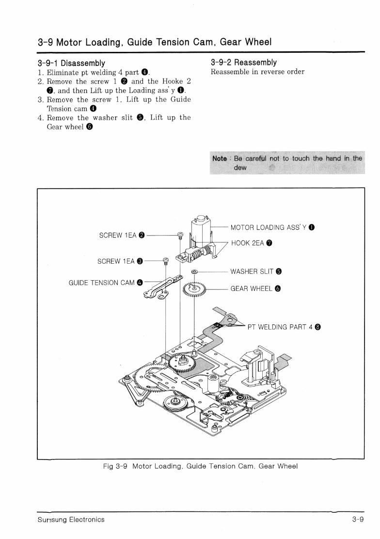
38-9 Motor Loading, Guide Tension Cam, Gear Wheel
3-9-1 Disassembly 3-9-2 Reassembly 1. Eliminate pt welding 4 part @. | Reassemble in reverse order
2. Remove the screw 1 @ and the Hooke 2 @, and then Lift up the Loading ass y @.
3. Remove the screw 1, Lift up the Guide
Tension cam @ 4. Remove the washer slit @, Lift up the
Gear wheel @
MOTOR LOADING ASS’ Y @ SCREW 1EA @
HOOK 2EA @
SCREW 1EA ©
GUIDE TENSION CAM @
Fig 8-9 Motor Loading, Guide Tension Cam, Gear Wheel
Sumsung Electronics 3-9
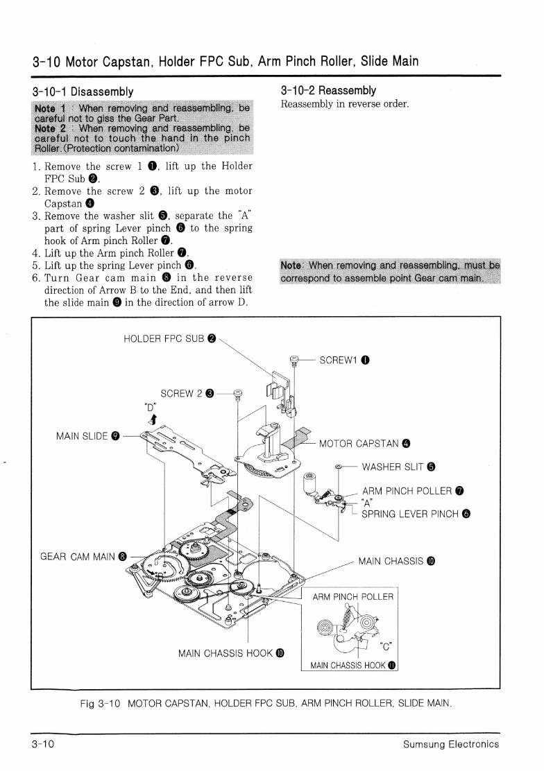
8-10 Motor Capstan, Holder FPC Sub, Arm Pinch Roller, Slide Main
3-10-1 Disassembly 3-10-2 Reassembly Reassembly in reverse order.
FPC Sub @. 2. Remove the screw 2 @, lift up the motor
Capstan @ 3. Remove the washer slit @, separate the “A’
part of spring Lever pinch @ to the spring
hook of Arm pinch Roller @. ._ Lift up the Arm pinch Roller @. . Lift up the spring Lever pinch ©. | _Turn Gear cam main @ in the reverse
direction of Arrow B to the End, and then lift
the slide main @ in the direction of arrow D.
HD Oe
HOLDER FPC SUB @
SCREW1 @
MAIN SLIDE @ MOTOR CAPSTAN @
WASHER SLIT @
ARM PINCH POLLER @ “A
SPRING LEVER PINCH @
GEAR CAM MAIN @ fo TY Ps MAIN CHASSIS @
MAIN CHASSIS HOOK @ MAIN CHASSIS HOOK @
Fig 3-10 MOTOR CAPSTAN, HOLDER FPC SUB, ARM PINCH ROLLER, SLIDE MAIN.
oat 8, Sumsung Electronics
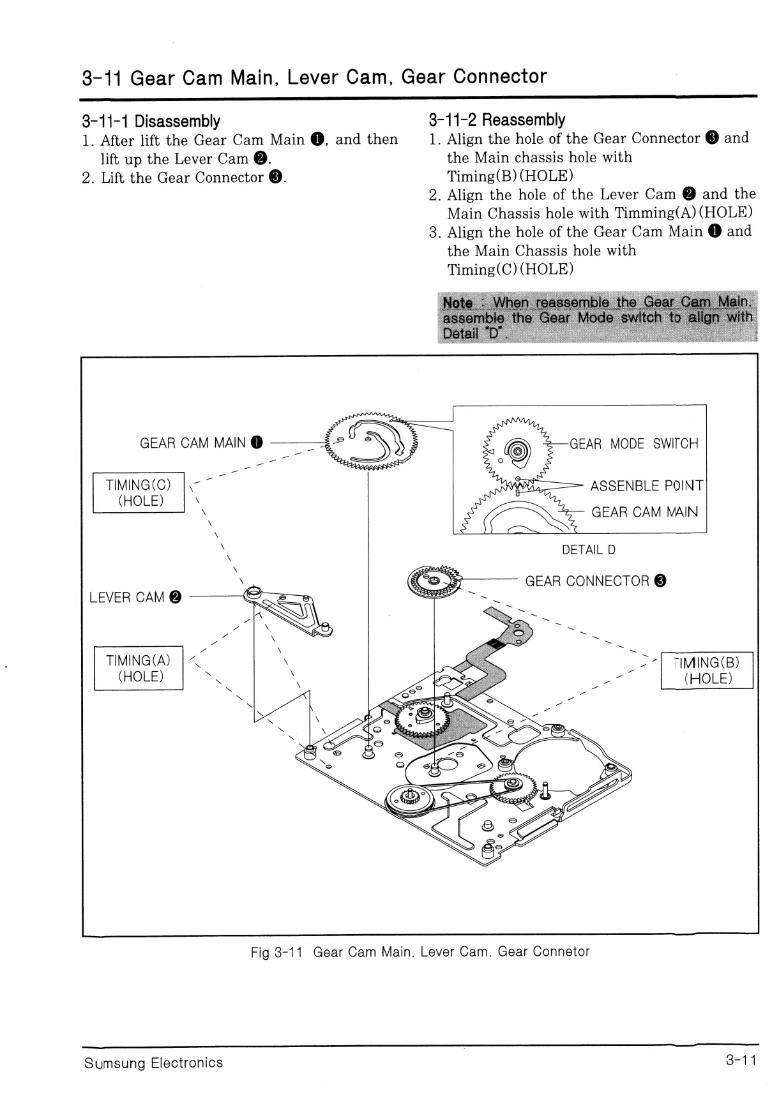
3-11 Gear Cam Main, Lever Cam, Gear Connector _ eee
em
3-11-1 Disassembly 3-11-2 Reassembly 1. After lift the Gear Cam Main @, and then 1. Align the hole of the Gear Connector @ and
lift up the Lever Cam @. the Main chassis hole with 2. Lift the Gear Connector @. Timing(B) (HOLE)
2. Align the hole of the Lever Cam @ and the Main Chassis hole with Timming(A) (HOLE)
3. Align the hole of the Gear Cam Main @ and the Main Chassis hole with
Timing(C) (HOLE)
GEAR CAM MAIN @ GEAR MODE SWITCH
TIMING(C) |.- 7 ASSENBLE POINT (HOLE) \
GEAR CAM MAIN
\
" | DETAIL D x peak,
\ (@ 37 GEAR CONNECTOR © LEVER CAM @ ee
TIMING(A) |“ (HOLE) *
Fig 8-11 Gear Cam Main, Lever Cam, Gear Connetor
eee eee ee eee eee ee ee eee ——
Sumsung Electronics 3-11
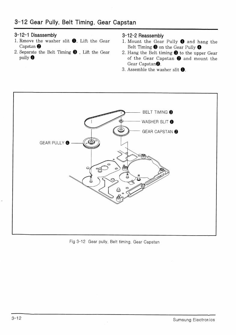
3-12 Gear Pully, Belt Timing, Gear Capstan
3-12-2 Reassembly 3-12-1 Disassembly 1. Rmove the washer slit @, Lift the Gear 1. Mount the Gear Pully @ and hang the
Capstan @ Belt Timing @ on the Gear Pully @ 2. Separate the Belt Timing @ , Lift the Gear 2. Hang the Belt timing ® to the upper Gear
pully @ | of the Gear Capstan @ and mount the Gear Capstan@.
3. Assemble the washer slit @.
BELT TIMING @
>———— WASHER SLIT @
GEAR CAPSTAN @
GEAR PULLY @
Fig 3-12 Gear pully, Belt timing. Gear Capstan
eS
OF lc | Sumsung Electronics


![Samsung Ps42q97hdx Ps42q97hdxeu Ps50q97hdx Ps50q97hdxeu [Sm]](https://img.pdfslide.us/doc/110x75/55cf9065550346703ba58d7e/samsung-ps42q97hdx-ps42q97hdxeu-ps50q97hdx-ps50q97hdxeu-sm.jpg)

![Samsung ML-2010 [Sm]](https://img.pdfslide.us/doc/110x75/5540408b550346466d8b4a61/samsung-ml-2010-sm.jpg)


![Samsung PN50A550 PN58A550 SchematicDiagram [SM]](https://img.pdfslide.us/doc/110x75/55cf8e47550346703b9069b6/samsung-pn50a550-pn58a550-schematicdiagram-sm.jpg)
![Samsung Beko Sdi42sdv3 [Sm]](https://img.pdfslide.us/doc/110x75/55cf9d77550346d033adc035/samsung-beko-sdi42sdv3-sm.jpg)
![Samsung Ps42c91hx [Sm]](https://img.pdfslide.us/doc/110x75/55cf97ef550346d03394886d/samsung-ps42c91hx-sm.jpg)