Embed Size (px)
Citation preview

Manual Car Jack for High Profile Vehicles
A Baccalaureate thesis submitted to the Department of Mechanical and Materials Engineering
College of Engineering and Applied Science University of Cincinnati
in partial fulfillment of the
requirements for the degree of
Bachelor of Science
in Mechanical Engineering Technology
by
David Barthelmas
April 2017
Thesis Advisor:
Professor Amir Salehpour
ii
TABLE OF CONTENTS
TABLE OF CONTENTS .......................................................................................................... II
LIST OF FIGURES ............................................. ERROR! BOOKMARK NOT DEFINED.
LIST OF TABLES ............................................... ERROR! BOOKMARK NOT DEFINED.
ABSTRACT ............................................................................................................................ III
PROBLEM DEFINITION AND RESEARCH ........................................................................ 1
PROBLEM STATEMENT........................................................................................................................................ 1 CUSTOMER FEATURES ........................................................................................................................................ 1
DESIGN .................................................................................................................................... 1
RESEARCH .......................................................................................................................................................... 1 DESIGN PROCESS ................................................................................................................................................ 2 DESIGN ALTERNATIVES ...................................................................................................................................... 3
DESIGN SELECTION ............................................................................................................. 5
BASE/ CONCEPT SELECTION ............................................................................................................................... 5 LEVER SELECTION .............................................................................................................................................. 7 INITIAL DESIGN .................................................................................................................................................. 8 PRODUCT REDESIGN ......................................................................................................................................... 10 FINITE ELEMENT ANALYSIS (FEA) .................................................................................................................. 10 FABRICATION ................................................................................................................................................... 14 ASSEMBLY DRAWINGS ..................................................................................................................................... 15
CONCLUSION ....................................................................................................................... 17
PROJECT MANAGEMENT .................................................................................................. 18
BIBLIOGRAPHY ................................................................................................................... 18
APPENDIX A ......................................................................................................................... 19
REVISED PART DRAWINGS ............................................................................................................................... 19
APPENDIX B ......................................................................................................................... 23
INITIAL PART DRAWINGS ................................................................................................................................. 23
iii
ABSTRACT
Automotive jacks have been around for years and there are dozens of different styles,
sizes and weight capacities. There are also very expensive hydraulic lift systems that can be
purchased to lift all 4 points of the car up.
The design of the manual car jack/stand will allow the user to be able to achieve greater
lift from a conventional household car jack. This jack/stand will be able to lift the vehicle
that has a higher than stock frame rail. This can occur on vehicles that have aftermarket lifted
suspensions or vehicles with a large amount of suspension travel. This will then allow the
individual to work on it in their driveway without needing an expensive, space consuming
lift.

iv

Manual Car Jack for High Profile Vehicles David Barthelmas
1
PROBLEM DEFINITION AND RESEARCH
PROBLEM STATEMENT
Automotive jacks have been around for years with dozens of different styles, sizes and
weight capacity. When typically working on a vehicle with a frail rail that is not at stock
height, items would have to be used to increase the usable height of the jack. There is an
alternative to this, which is an expensive automotive hydraulic lift that lifts the whole vehicle
at four contact points all at the same time.
The design of the manual car jack/stand will allow the user to be able to increase the
usable height of existing car jacks without using items such as bricks, blocks, or pieces of
scrap metal. This jack will be able to lift a vehicle that is high profile with more than typical
suspension travel, thus allowing the individual to work on it in their driveway without
needing an expensive, space consuming lift.
CUSTOMER FEATURES
Features that sets this product apart from others include:
• Safe/strong
• Easy to move
• Easy to adjust/ operate
• Easy to store
• Light in weight
• Aesthetically pleasing
Objectives:
This car jack/stand will be able to lift vehicles safely and with ease so that the
operator can change/ rotate tires on vehicles with high profiles or flexible suspensions.
Lastly, this product should be able to be used with different styles car jacks to accommodate
customers that already may have different car jacks. These may include scissor jacks and
rolling hydraulic jacks.
DESIGN
RESEARCH
Car jacks have had many advancements from worm gear scissor jacks to hydraulic lifts.
The issue that arises with most car jacks is that they are not designed for vehicles that have
had aftermarket parts added to the stock vehicle. These types of vehicles will be able to
articulate to a point where the maximum lift height of the jack (typically 19-23 inches) will
not be able to lift the vehicles tires off the ground. To achieve the extra height that is needed
to lift the vehicle off of the ground, something needs to be added either above or below the
jack. Typically, a block of wood or a cinderblock is used to achieve the extra height. With
more and more people adding aftermarket parts to their vehicles, there will be an increased
need for people to be able to work on their vehicles safely.

Manual Car Jack for High Profile Vehicles David Barthelmas
2
Initial research includes the following products and others that are not depicted. Product
(1) is a typical jack stand that you can purchase at your local auto parts stores. This product is
simply a device to hold the weight of the vehicle while working. This can only be removed
once the weight of the vehicle is lifted by the car jack. Product (2) is a hydraulic rolling jack
that can also be purchased at your local auto parts stores. This product is used by most car
enthusiast due to its ease of use, rapid pump features for quick lofting and lowering, and its
lifting height. These jacks come in two typical maximum lifting heights of 19 ¾ inches and
23 ¾ inches. These heights work for most vehicles, but when the vehicle can articulate with
lots of suspension travel this is not high enough.
(1) (2)
DESIGN PROCESS
The design process was all centered around the core principle that this product needed to
be safe, functional and cost effective all at the same time. This means reducing material
thickness to an acceptable and safe thickness, and adding structural support where needed.
To narrow down what kind of jack and stand combination would encompass these features,
sketches of possible designs were made. Then determined what features could be functional
and incorporated. If they were not functional or feasible, then those were eliminated. The
parts that were feasible were transferred to the next idea etc. This is the flow of the Design
Alternatives section.
Once the process started to narrow to a design that was safe, functional and achieved all
my design specifications, the design was brought into a solid model using Solidworks. This is
where the design was altered to make all the components and features mesh into one fully
functional and fully defined model. Multiple revisions on some components were made and
documented in the Appendix section.

Manual Car Jack for High Profile Vehicles David Barthelmas
3
DESIGN ALTERNATIVES
• Car Jack with jack point
on side.
• Accommodate all jacks
• Bad with bending moment
• Tough to manufacture
• Car Jack with jack point
in the middle
• Accommodate all jacks
• Two supporting polls to
stabilize structure
• Two contact points
• Collapsible
• Mounting bar to roller-
type jack
• Non-universal device
• Two contact points
• Collapsible

Manual Car Jack for High Profile Vehicles David Barthelmas
4
• Jack goes on top of block
instead of on the ground
• Limits variety of jacks
that can be used to bottle
and scissor type
• Cumbersome
• Difficult to manufacture
• Car Jack with jack point
on side.
• Accommodate all jacks
• Bad with bending
moment
• Tough to manufacture
• Single Jack contact point
• Collapsible
• Use of multiple jack
• Swivel ends for two
different types of contact
points on the car
• Two contact points on the
vehicle
• Pyramid style jack and
jack stand combination
• Two contact points on the
vehicle
• One central jack point
• Possible issue with
pinching on jack stand
post

Manual Car Jack for High Profile Vehicles David Barthelmas
5
DESIGN SELECTION
BASE/ CONCEPT SELECTION
Concept Section Sketch
The selected product is a pyramid style jack and jack stand combination with one contact
point on the vehicle. This product will be able to be used with most major jacks on the
market today including scissor and rolling hydraulic style. The product will feature an
opening for the jack to be placed inside of the pyramid to be able to contact the lifting post
located in the center of the jack stand. The post will feature a locking mechanism that will
hold the lifting post at the desired height.
• Folding feature on
pyramid style jack and
jack stand combination
• Locking pin when in use
to keep system open

Manual Car Jack for High Profile Vehicles David Barthelmas
6
Concept Detail Drawing of Base and Lever
Concept Detail Drawing of Post and Contact Plate
Concept Detail Drawing of Base and Lever and Concept Detail Drawing of Post and
Contact Plate are preliminary sketches that were used to make the Solidworks drawings.
Within Solidworks, a fully defined and functioning model will be created in order to test fit,
strength and functionality.

Manual Car Jack for High Profile Vehicles David Barthelmas
7
LEVER SELECTION
Design 1 Design 2 Design 3
Parameter Weight Rating Total Rating Total Rating Total
Safety 0.6 6 3.6 5 3 3 1.8
Ease of use 0.2 2 0.4 7 1.4 3 0.6
Product Cost 0.1 2 0.2 7 0.7 8 0.8
Ease of Manufacturing
0.1 2 0.2 7 0.7 8 0.8
Sum of Weight and Rating
1 4.4 5.8 4
Table 1: Weights and rating table
From the table 1, the single lever (design 2) was determined to be the best type of
locking/ release for this system. The single lever design fulfilled all the engineering
parameters that were laid out for this design to be successful. The ratings were determined by
how safe, how easy to use the system is, how much the product would cost, and how easy it
would be to manufacture. These factors were taken into consideration and then given a rating
on a scale from 1-10. This rating was then multiplied by the weight and summed.
Design 1
Design 2
Design 3

Manual Car Jack for High Profile Vehicles David Barthelmas
8
INITIAL DESIGN
Multiple designs and revolving design modifications were made while making the solid
model in Solidworks. The revolving design modifications worked as follows:
1. Model design of multiple concepts
2. Assemble concepts
3. Test for fitment, aesthetics, and feasibility
4. Repeat steps 1-3 if the concept fails
Revision 1
Revisions were captured after they had been determined that they will not function and
satisfy the engineering characteristics. Revision 1 was initially made from the concept that
was hand drawn in the Base/ Concept Selection category. This concept featured an open front
to allow the user to insert the jack, tall tapered structure, and open ports for weight reduction
and design aesthetics. This revision was eventually modified due to the open front design and
the open ports allowing for too much bending which caused the structure to butterfly open
when a loading force was applied to the top of the structure.

Manual Car Jack for High Profile Vehicles David Barthelmas
9
Revision 2
Revision 2 aided in correcting the problems that arose in revision 1. Revision 2 featured
a slightly larger top to make the loading force move down the walls of the structure rather
than trying to flatten he structure. Also, the side ports were rounded to decrease point loading
on sharp corners. The side ports were then made to be smaller to increase the amount of
material on the walls thus slightly increasing the strength of the structure. Then the front of
the front of the structure was modified. A front wall section was added where the jack would
be placed. Due to ease of manufacturing concerns, the base was then split into two sections
which will be welded together. This is all depicted in above.
Initial Final Design (Revision 3)
Revision 3 is the culmination of all the revisions and design alterations that were made.
This revision consists of a shorter, more ridged, and stronger design. The base is made up of
two pieces and welded together. The front opening will be able to accommodate different
kinds of jacks. The opening is wide and tall enough that a hydraulic style jack will be able to
roll in and contact the base and extend up without hitting the jack stand.

Manual Car Jack for High Profile Vehicles David Barthelmas
10
PRODUCT REDESIGN
After fully defining the initial design, Solidworks was used to predict the total weight of
the system at 130 pounds. This would prove to be unacceptable and would not satisfy the
customer and engineering requirements. A redesign of the ratcheting style locking post and
the post was needed to decrease the weight of the system.
The post was the first component to be redesigned. The solid steel 3x5 inch post was
where most the weight issues were concentrated. This post was changed from a solid steel
post to a hollow square tube post.
The design choice to switch to a hollow square tube did not allow for the previously
designed ratcheting locking mechanism. The change to the hollow square tube made the
locking mechanism to have to change to a simpler design. The least favorable pin locking
mechanism was the best match for the hollow square tube. To accommodate for the new
hollow square tube, the ratchet house was replaced with a square sleeve and there was a need
for an additional supporting brace to be inserted due to the loss of stability with the change of
the ratcheting housing.
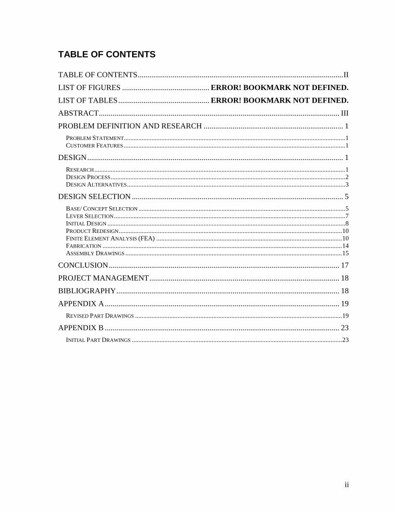
FINITE ELEMENT ANALYSIS (FEA)
The finite element analysis (FEA) was performed on the key components of the system.
This was used to determine if the component was structurally sound and able to withstand the
forces applied. The applied force that was used for these components was a 10,000-pound
static force applied where the force would be concentrated in a loaded scenario (pink
arrows). This load was determined by the curb weight of my test vehicle at approximately
5,000 pounds and a safety factor of 2, resulting in a 10,000 pound load. The main
Weight = 29.30 lbs Weight = 11.40 lbs

Manual Car Jack for High Profile Vehicles David Barthelmas
11
components that were evaluated in FEA fared well to the 10,000-pound load.
Two materials and thicknesses were tested in FEA to determine at what point the
material would fail. FEA determined that with the same outer dimension of 3x3 inches and
same size hole at 0.75 inches, the wall thickness needed to be 0.25 inches with 1020 cold
rolled steel and 0.125 inches with 1045 cold rolled steel. The maximum yield stress that
occurred for the 0.25 inch 1020 cold rolled steel was 206,000,000 N/m^2 with a maximum
yield stress before plastic deformation of 350,000,000 N/m^2. The maximum yield stress that
occurred for the 0.125 inch 1045 cold rolled steel was 455,100,000 N/m^2 with a maximum
yield stress before plastic deformation of 530,000,000 N/m^2. The increased strength of the
1045 cold rolled steel allowed for half the wall thickness. For this project, 1020 cold rolled
steel was the only financially and available option to use. For the rest of the FEA
calculations, 1020 cold rolled steel was assumed as the material.
FEA 1: 13x3x0.25 Inch Square Tune 1020
Cold Rolled Steel
FEA 2: 3x3x0.125 Inch Square Tune 1045 Cold
Rolled Steel

Manual Car Jack for High Profile Vehicles David Barthelmas
12
FEA 3: Post Sleeve
The maximum yield stress that occurred for the 0.25 inch 1020 cold rolled steel post
sleeve was 212,800,000 N/m^2 with a maximum yield stress before plastic deformation of
350,000,000 N/m^2. The highest amount of concentration was located at the bottom of the
hole where the pin would be resting in a loaded condition. No plastic deformation occurred
when loaded and this design was determined to be acceptable for use.
FEA 4: Base Stress
FEA did not represent the stresses properly on the base piece. This is due to the
unrealisic constrainets and scenerio that Solidworks assumes. Witht this, Solidworks assumes
that the structure will be loaded soalely on the 11 guage sheet at the very top. But in reality,
there is another piece that will mirror it and a support piece that will prevent twisting and aid
in keeping the struture from collapsing. This FEA study determined that the maximum yeaild
Manual Car Jack for High Profile Vehicles David Barthelmas
13
stress was 16,490,000,000 N/m^2 wich is well above the yeild strength of the material it
350,000,000 N/m^2. With the above conditions of the support and improper loading in FEA,
the base was determined to be able to fair the load based on market research. Typical jack
stands are made from 10 to 14-gauge sheet metal. From this, the 11 gauge sheet metal was
determined to be suitable for this design.
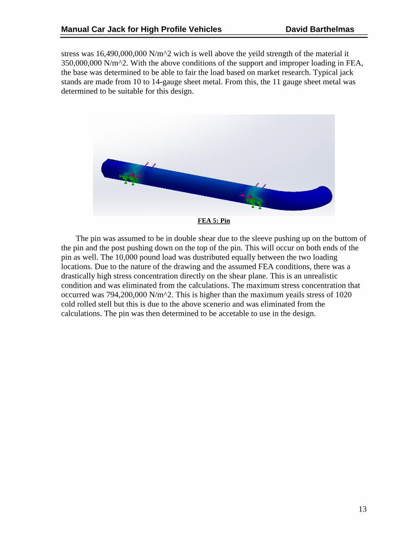
FEA 5: Pin
The pin was assumed to be in double shear due to the sleeve pushing up on the buttom of
the pin and the post pushing down on the top of the pin. This will occur on both ends of the
pin as well. The 10,000 pound load was dustributed equally between the two loading
locations. Due to the nature of the drawing and the assumed FEA conditions, there was a
drastically high stress concentration directly on the shear plane. This is an unrealistic
condition and was eliminated from the calculations. The maximum stress concentration that
occurred was 794,200,000 N/m^2. This is higher than the maximum yeails stress of 1020
cold rolled stell but this is due to the above scenerio and was eliminated from the
calculations. The pin was then determined to be accetable to use in the design.

Manual Car Jack for High Profile Vehicles David Barthelmas
14
FABRICATION
Fabrication of the base was a 5-step process. Initially this was thought to be a 2-step
process, but with the machinery available 3 extra steps were needed. The steps to fabricate
the base included:
• Plasma cutting 11-gauge sheet metal to shape
• Cutting 2-inch relief cuts along the bed lines to decrease material to be bent
• Bending the sheet metal at 10-20 degree each per 5 bend lines
• Tig welding relief cuts closed
• Grinding surface flat
After both frame pieces were finished and grinded smooth, the two pieces were spot
welded so that the structure sat flat. After the seam was welded, the brace was welded to the
sleeve and primed. The sleeve and brace needed to be primed and painted before fitted inside
of the base frame due to limited access to that area after fully assembled. Once the sleeve is
inserted in the base and welded, the jack post contact is welded to the post. This was then
primed and painted as well in the areas that will be contained in the sleeve when fully
assembled. Then the end effector contact is welded to the post after the post is slid through
the sleeve.
Relief Cuts Tig Fill Welds Finish Grinding

Manual Car Jack for High Profile Vehicles David Barthelmas
15
ASSEMBLY DRAWINGS
Initial Design Assembly Drawing: Fully Assembled
Spot Weld Frame
Level
Prime and Paint
Sleeve and Brace
Post With 7 Height
Selections

Manual Car Jack for High Profile Vehicles David Barthelmas
16
Initial Design Assembly Drawing: Exploded View with BOM
Final Design Assembly Drawing: Fully Assembled

Manual Car Jack for High Profile Vehicles David Barthelmas
17
Final Design Assembly Drawing: Exploded View with BOM
CONCLUSION
The conclusion from the research, design, design selection, and FEA is that all the
components are strong enough to withstand the forces needed for the jack stand assembly to
function properly. Each key individual part was put through the required tests to establish its
functionality and safety. Therefore, it can be said that once the individual parts are assembled
as one unit, it will be just as strong, if not stronger.
The initial design of the jack stand with the solid rectangular post weighed 130 pounds
and was determined to not be feasible for the needed application. After the redesign, the
system weighed 30 pounds. This weight is better suited for the application of the jack stand.
After fabrication and product testing, there are a couple changes that could be made in
order to make the product function better for the operator. First off, 1045 cold rolled steel
would be a better option for this product due to its increased structural strength. This will
allow for the wall thicknesses to be decreased by half, which will then decrease the overall
weight of the product. A key feature of the design is the alignment of the holes for the
locking pin. This was an issue with the product that was produced due to the substantial gap
between the sleeve and the post. If this could be reduced to allow for better meshing, the
system would operate much better.

Manual Car Jack for High Profile Vehicles David Barthelmas
18
PROJECT MANAGEMENT
The following schedule is subject to change.
Table 1: Tentative Schedule
Table 2: Budget
BIBLIOGRAPHY 1. ASEDeals Automotive Service Equipment. ASEDeals Automotive Service Equipment Web
Site. [Online] [Cited: September 26, 2016.] http://www.asedeals.com/jacks/aluminum-
jacks/ranger-aluminum-racing-jack-rfj-4000al/.
2. Harbor Freight Tools. [Online] 2016. [Cited: 09 26, 2016.]
http://www.harborfreight.com/6-ton-jack-stand-set-38847.html.

19
APPENDIX A
REVISED PART DRAWINGS
Part Drawing 1: Post
Part Drawing 2: Base

20
Part Drawing 3: Brace
Part Drawing 4: End Effector Contact

21
Part Drawing 5: Jack Post Contact
Part Drawing 6: Outer Sleeve

22
Assembly Drawing 1
Assembly Drawing 2

23
APPENDIX B
INITIAL PART DRAWINGS
Part Drawing 7: Base Part Drawing

24
Part Drawing 8: End Effector Base Part Drawing
Part Drawing 9: End Effector Contact Part Drawing
25
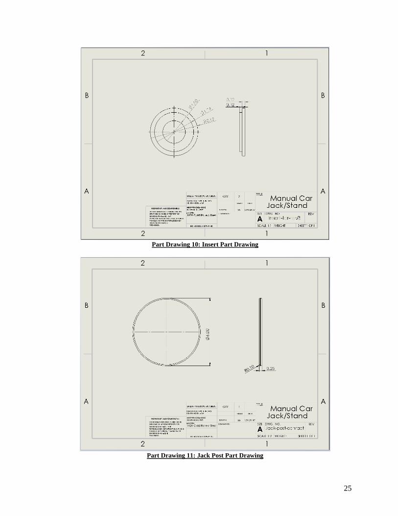
Part Drawing 10: Insert Part Drawing
Part Drawing 11: Jack Post Part Drawing
26
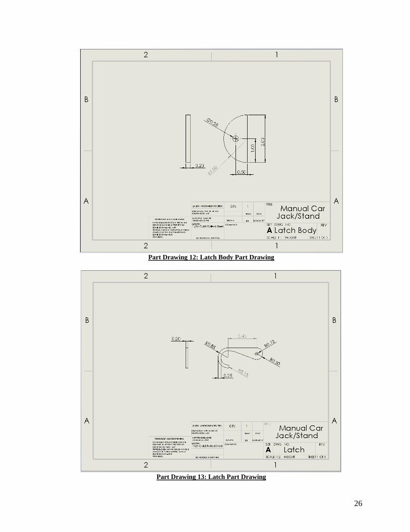
Part Drawing 12: Latch Body Part Drawing
Part Drawing 13: Latch Part Drawing

27
Part Drawing 14: Ratchet Housing Part Drawing
Part Drawing 15: Release Bar Part Drawing

28
Part Drawing 16: Shaft Part Drawing
Part Drawing 17: Tooth Stopper Part Drawing

29

30

31