Embed Size (px)
Citation preview
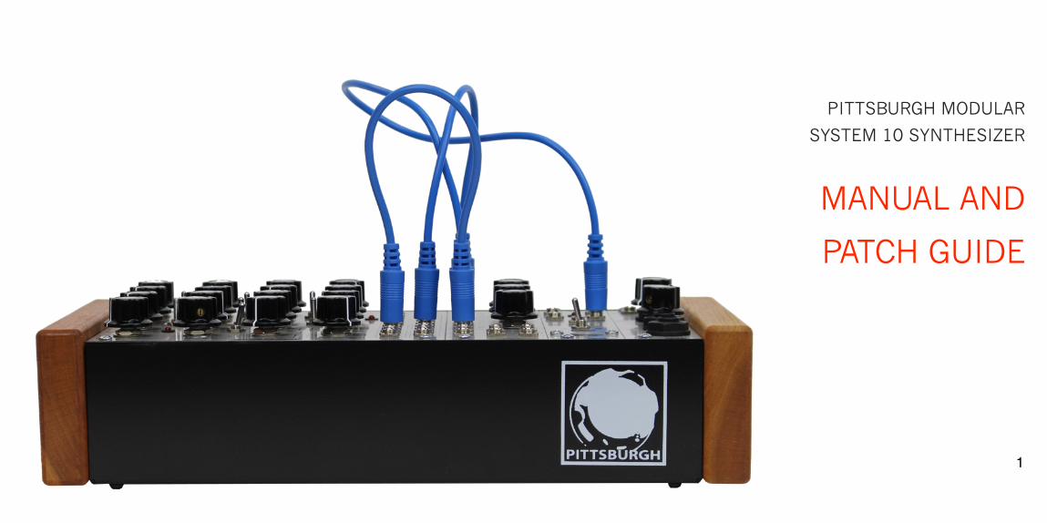
!!PITTSBURGH MODULAR
SYSTEM 10 SYNTHESIZER
!MANUAL AND
PATCH GUIDE !!!!!!!!!
�1
Important Instructions – PLEASE READ!!!Read Instructions: Please read the System 10 Synthesizer manual completely before use and retain for future reference. !IMPORTANT Ribbon Cable Power Information: The System 10 combines a set of individual modules to create a complete instrument. The individual modules can be rearranged, removed, and replaced with any compatible eurorack modules from Pittsburgh Modular and other manufacturers. !The System 10 uses a standard 10 pin eurorack power ribbon cable to connect the modules to the internal bipolar +/-12v power
supply. Please pay very close attention to the orientation of the ribbon cable when adding and removing modules. The stripe on the ribbon cable marks -12v. This stripe needs to line up with the -12v pins on the power rail and the -12v pins on the module. Failure to match up the pins correctly can result in damage to one or all the modules in the System 10. On the power rail, the -12v pins are clearly labeled. On the individual modules, the positive and negative sides of the pin connectors are labeled next to the power header on either the top or bottom of the PCB. !Do NOT remove individual modules from the System 10 while synthesizer is plugged in. !Do NOT unplug ribbon cables from the System 10 or individual modules while the System 10 is plugged in. !!!!
�2
Table of Contents !!!!!!!Important Instructions ………………….…… 2 Table of Contents …….…….…………….…… 3 Case and Power Specifications ………….… 4 System 10 Package Contents………….…… 4 An Introduction to Modular Synthesis….… 5 Modular Signal Paths ……………..........….. 6 Individual Modules ……………………..… 7-18 Patching a Modular Synthesizer ……..…. 19 Patch Guides …………………….….…… 20-29 1 Year Limited Warranty……………….…… 30 Service and Other Information ….….….… 31
�3
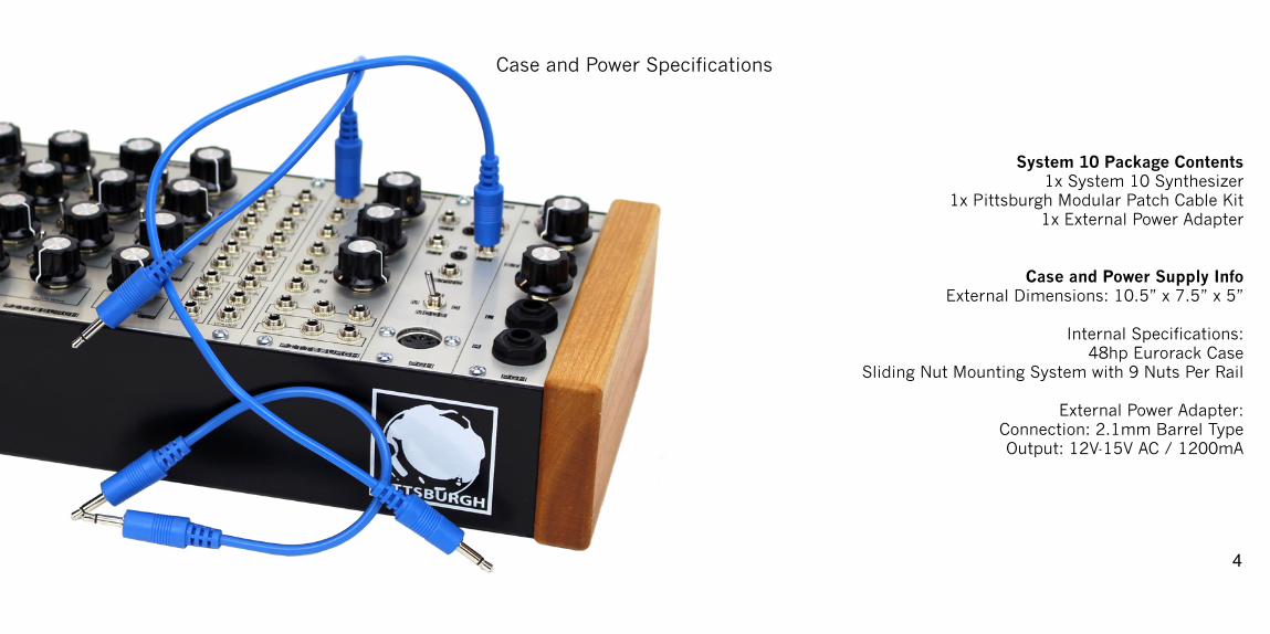
Case and Power Specifications !!!!System 10 Package Contents 1x System 10 Synthesizer
1x Pittsburgh Modular Patch Cable Kit 1x External Power Adapter !!
Case and Power Supply Info External Dimensions: 10.5” x 7.5” x 5”
Internal Specifications:
48hp Eurorack Case Sliding Nut Mounting System with 9 Nuts Per Rail !
External Power Adapter: Connection: 2.1mm Barrel Type Output: 12V-15V AC / 1200mA !!!
�4
An Introduction to Modular Synthesis! !
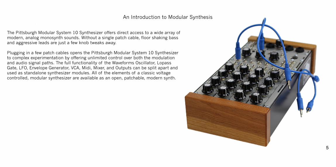
The Pittsburgh Modular System 10 Synthesizer offers direct access to a wide array of modern, analog monosynth sounds. Without a single patch cable, floor shaking bass and aggressive leads are just a few knob tweaks away. !Plugging in a few patch cables opens the Pittsburgh Modular System 10 Synthesizer to complex experimentation by offering unlimited control over both the modulation and audio signal paths. The full functionality of the Waveforms Oscillator, Lopass Gate, LFO, Envelope Generator, VCA, Midi, Mixer, and Outputs can be split apart and used as standalone synthesizer modules. All of the elements of a classic voltage controlled, modular synthesizer are available as an open, patchable, modern synth. !!
�5
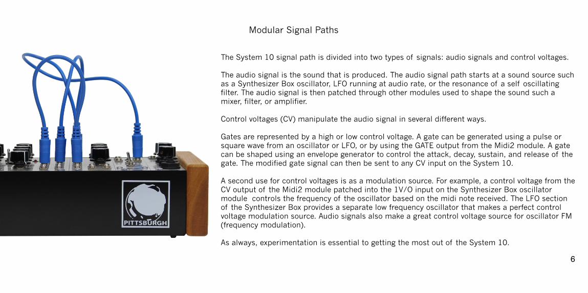
Modular Signal Paths!!The System 10 signal path is divided into two types of signals: audio signals and control voltages. !The audio signal is the sound that is produced. The audio signal path starts at a sound source such as a Synthesizer Box oscillator, LFO running at audio rate, or the resonance of a self oscillating filter. The audio signal is then patched through other modules used to shape the sound such a mixer, filter, or amplifier. !Control voltages (CV) manipulate the audio signal in several different ways. !Gates are represented by a high or low control voltage. A gate can be generated using a pulse or square wave from an oscillator or LFO, or by using the GATE output from the Midi2 module. A gate can be shaped using an envelope generator to control the attack, decay, sustain, and release of the gate. The modified gate signal can then be sent to any CV input on the System 10. !A second use for control voltages is as a modulation source. For example, a control voltage from the CV output of the Midi2 module patched into the 1V/O input on the Synthesizer Box oscillator module controls the frequency of the oscillator based on the midi note received. The LFO section of the Synthesizer Box provides a separate low frequency oscillator that makes a perfect control voltage modulation source. Audio signals also make a great control voltage source for oscillator FM (frequency modulation). !As always, experimentation is essential to getting the most out of the System 10.
�6
Individual Modules
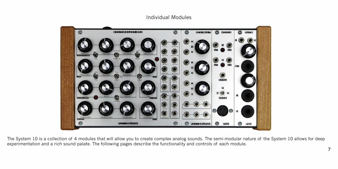
!The System 10 is a collection of 4 modules that will allow you to create complex analog sounds. The semi-modular nature of the System 10 allows for deep experimentation and a rich sound palate. The following pages describe the functionality and controls of each module.
�7
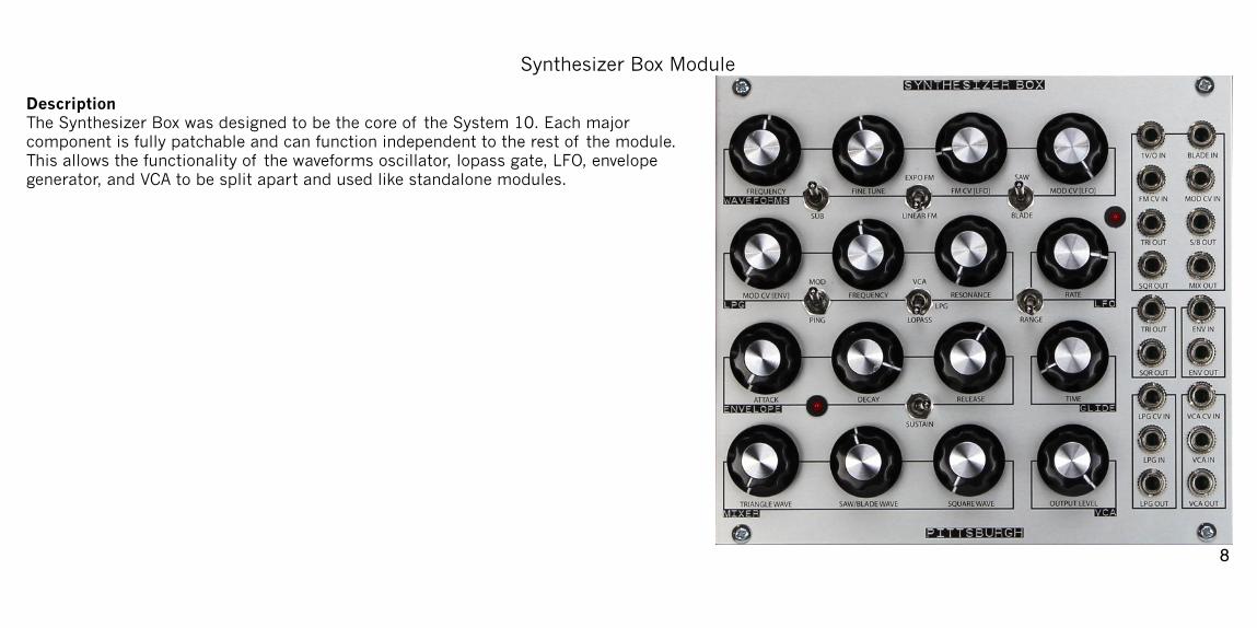
Synthesizer Box Module!Description The Synthesizer Box was designed to be the core of the System 10. Each major component is fully patchable and can function independent to the rest of the module. This allows the functionality of the waveforms oscillator, lopass gate, LFO, envelope generator, and VCA to be split apart and used like standalone modules. !!!!!!!!!!!!!!!!!!
�8
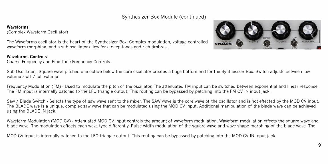
Synthesizer Box Module (continued)!Waveforms (Complex Waveform Oscillator) The Waveforms oscillator is the heart of the Synthesizer Box. Complex modulation, voltage controlled waveform morphing, and a sub oscillator allow for a deep tones and rich timbres. !Waveforms Controls Coarse Frequency and Fine Tune Frequency Controls !Sub Oscillator - Square wave pitched one octave below the core oscillator creates a huge bottom end for the Synthesizer Box. Switch adjusts between low volume / off / full volume !Frequency Modulation (FM) - Used to modulate the pitch of the oscillator, The attenuated FM input can be switched between exponential and linear response. The FM input is internally patched to the LFO triangle output. This routing can be bypassed by patching into the FM CV IN input jack. !Saw / Blade Switch - Selects the type of saw wave sent to the mixer. The SAW wave is the core wave of the oscillator and is not effected by the MOD CV input. The BLADE wave is a unique, complex saw wave that can be modulated using the MOD CV input. Additional manipulation of the blade wave can be achieved using the BLADE IN jack. !Waveform Modulation (MOD CV) - Attenuated MOD CV input controls the amount of waveform modulation. Waveform modulation effects the square wave and blade wave. The modulation effects each wave type differently. Pulse width modulation of the square wave and wave shape morphing of the blade wave. The !MOD CV input is internally patched to the LFO triangle output. This routing can be bypassed by patching into the MOD CV IN input jack.
�9
Synthesizer Box Module (continued)!Waveforms Patch Points 1V/O IN - One volt per octave input. BLADE IN - Blade wave manipulation input. FM CV IN - Frequency modulation input overrides internal routing to allow for external modulation. MOD CV IN - Waveform modulation input overrides internal routing to allow for external modulation.TRI OUT - Post mixer triangle wave output. S/B OUT - Post mixer saw or blade wave output. SQR OUT - Post mixer square wave output. MIX OUT - Mixer output includes triangle, saw/blade, square, and sub oscillator waveforms. !!!!!!!!!!!!!!!
�10
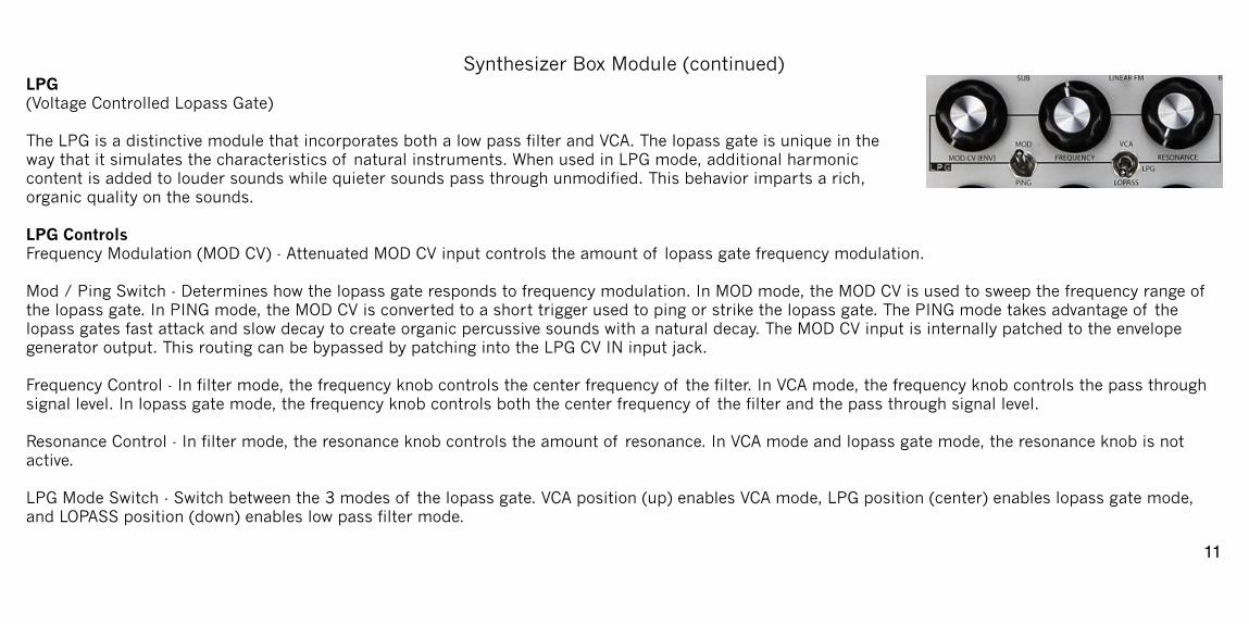
Synthesizer Box Module (continued)LPG (Voltage Controlled Lopass Gate) The LPG is a distinctive module that incorporates both a low pass filter and VCA. The lopass gate is unique in the way that it simulates the characteristics of natural instruments. When used in LPG mode, additional harmonic content is added to louder sounds while quieter sounds pass through unmodified. This behavior imparts a rich, organic quality on the sounds. !LPG Controls Frequency Modulation (MOD CV) - Attenuated MOD CV input controls the amount of lopass gate frequency modulation. !Mod / Ping Switch - Determines how the lopass gate responds to frequency modulation. In MOD mode, the MOD CV is used to sweep the frequency range of the lopass gate. In PING mode, the MOD CV is converted to a short trigger used to ping or strike the lopass gate. The PING mode takes advantage of the lopass gates fast attack and slow decay to create organic percussive sounds with a natural decay. The MOD CV input is internally patched to the envelope generator output. This routing can be bypassed by patching into the LPG CV IN input jack. !Frequency Control - In filter mode, the frequency knob controls the center frequency of the filter. In VCA mode, the frequency knob controls the pass through signal level. In lopass gate mode, the frequency knob controls both the center frequency of the filter and the pass through signal level. !Resonance Control - In filter mode, the resonance knob controls the amount of resonance. In VCA mode and lopass gate mode, the resonance knob is not active. !LPG Mode Switch - Switch between the 3 modes of the lopass gate. VCA position (up) enables VCA mode, LPG position (center) enables lopass gate mode, and LOPASS position (down) enables low pass filter mode.
�11
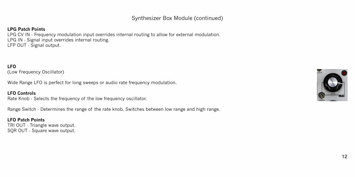
Synthesizer Box Module (continued)!LPG Patch Points LPG CV IN - Frequency modulation input overrides internal routing to allow for external modulation. LPG IN - Signal input overrides internal routing. LFP OUT - Signal output. !!!LFO (Low Frequency Oscillator) Wide Range LFO is perfect for long sweeps or audio rate frequency modulation. !LFO Controls Rate Knob - Selects the frequency of the low frequency oscillator. !Range Switch - Determines the range of the rate knob. Switches between low range and high range. !LFO Patch Points TRI OUT - Triangle wave output. SQR OUT - Square wave output. !!!
�12
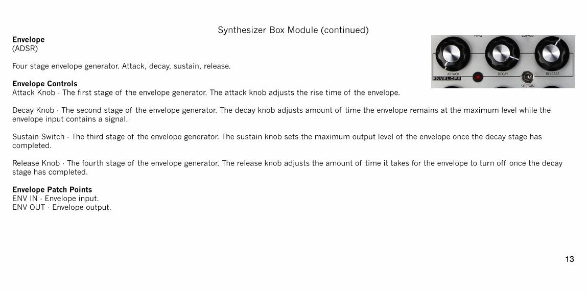
Synthesizer Box Module (continued)Envelope (ADSR) Four stage envelope generator. Attack, decay, sustain, release. !Envelope Controls Attack Knob - The first stage of the envelope generator. The attack knob adjusts the rise time of the envelope. !Decay Knob - The second stage of the envelope generator. The decay knob adjusts amount of time the envelope remains at the maximum level while the envelope input contains a signal. !Sustain Switch - The third stage of the envelope generator. The sustain knob sets the maximum output level of the envelope once the decay stage has completed. !Release Knob - The fourth stage of the envelope generator. The release knob adjusts the amount of time it takes for the envelope to turn off once the decay stage has completed. !Envelope Patch Points ENV IN - Envelope input. ENV OUT - Envelope output. !!!!
�13
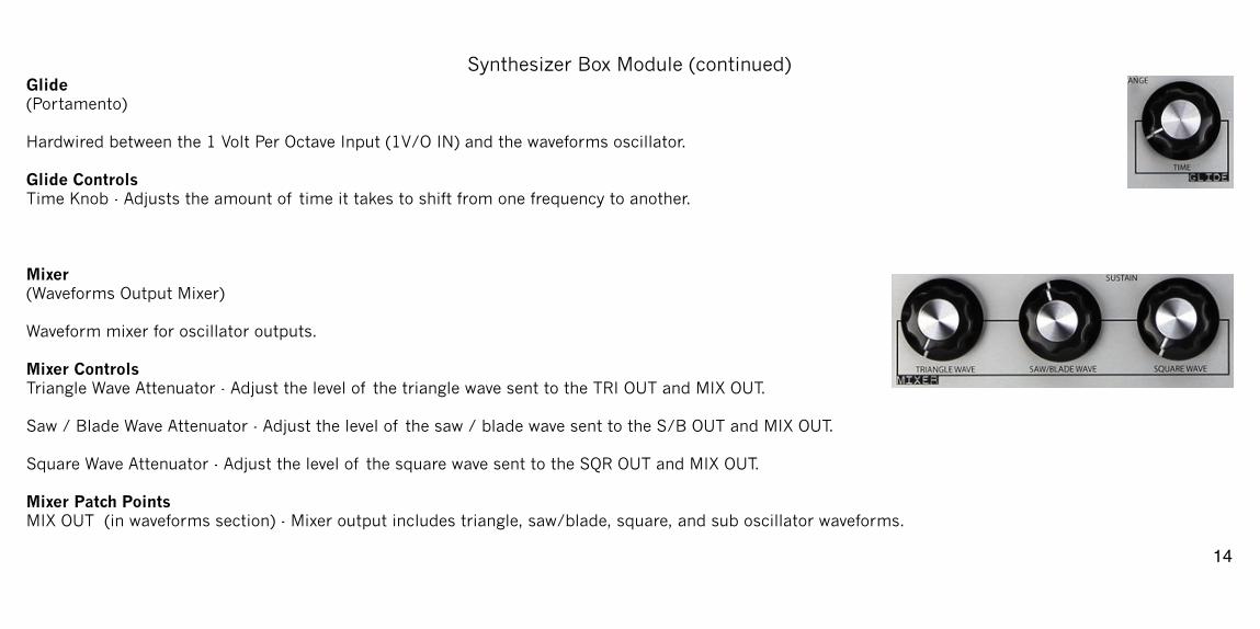
Synthesizer Box Module (continued)Glide (Portamento) !Hardwired between the 1 Volt Per Octave Input (1V/O IN) and the waveforms oscillator. !Glide Controls Time Knob - Adjusts the amount of time it takes to shift from one frequency to another. !!!Mixer (Waveforms Output Mixer) !Waveform mixer for oscillator outputs. !Mixer Controls Triangle Wave Attenuator - Adjust the level of the triangle wave sent to the TRI OUT and MIX OUT. !Saw / Blade Wave Attenuator - Adjust the level of the saw / blade wave sent to the S/B OUT and MIX OUT. !Square Wave Attenuator - Adjust the level of the square wave sent to the SQR OUT and MIX OUT. !Mixer Patch Points MIX OUT (in waveforms section) - Mixer output includes triangle, saw/blade, square, and sub oscillator waveforms.
�14
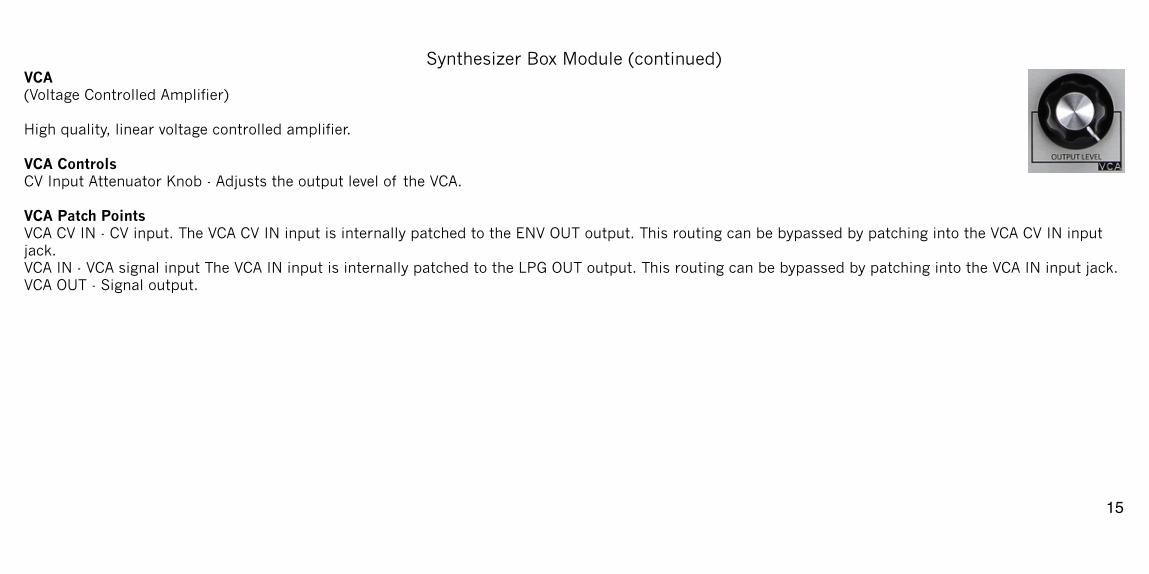
Synthesizer Box Module (continued)VCA (Voltage Controlled Amplifier) High quality, linear voltage controlled amplifier. !VCA Controls CV Input Attenuator Knob - Adjusts the output level of the VCA. !VCA Patch Points VCA CV IN - CV input. The VCA CV IN input is internally patched to the ENV OUT output. This routing can be bypassed by patching into the VCA CV IN input jack. VCA IN - VCA signal input The VCA IN input is internally patched to the LPG OUT output. This routing can be bypassed by patching into the VCA IN input jack. VCA OUT - Signal output. !!!!!!!!!!!
�15
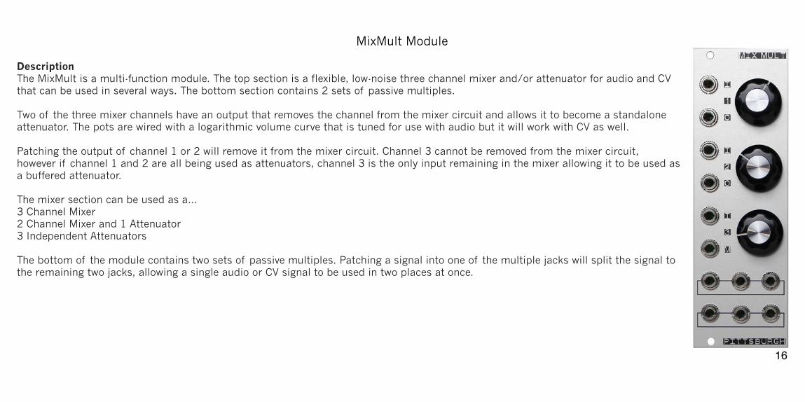
MixMult Module!Description The MixMult is a multi-function module. The top section is a flexible, low-noise three channel mixer and/or attenuator for audio and CV that can be used in several ways. The bottom section contains 2 sets of passive multiples. !Two of the three mixer channels have an output that removes the channel from the mixer circuit and allows it to become a standalone attenuator. The pots are wired with a logarithmic volume curve that is tuned for use with audio but it will work with CV as well. !Patching the output of channel 1 or 2 will remove it from the mixer circuit. Channel 3 cannot be removed from the mixer circuit, however if channel 1 and 2 are all being used as attenuators, channel 3 is the only input remaining in the mixer allowing it to be used as a buffered attenuator. !The mixer section can be used as a… 3 Channel Mixer 2 Channel Mixer and 1 Attenuator 3 Independent Attenuators !The bottom of the module contains two sets of passive multiples. Patching a signal into one of the multiple jacks will split the signal to the remaining two jacks, allowing a single audio or CV signal to be used in two places at once. !!!!!
�16
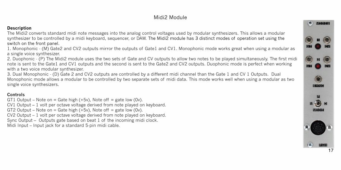
Midi2 Module!Description The Midi2 converts standard midi note messages into the analog control voltages used by modular synthesizers. This allows a modular synthesizer to be controlled by a midi keyboard, sequencer, or DAW. The Midi2 module has 3 distinct modes of operation set using the switch on the front panel. 1. Monophonic - (M) Gate2 and CV2 outputs mirror the outputs of Gate1 and CV1. Monophonic mode works great when using a modular as a single voice synthesizer. 2. Duophonic - (P) The Midi2 module uses the two sets of Gate and CV outputs to allow two notes to be played simultaneously. The first midi note is sent to the Gate1 and CV1 outputs and the second is sent to the Gate2 and CV2 outputs. Duophonic mode is perfect when working with a two voice modular synthesizer. 3. Dual Monophonic - (D) Gate 2 and CV2 outputs are controlled by a different midi channel than the Gate 1 and CV 1 Outputs. Dual Monophonic mode allows a modular to be controlled by two separate sets of midi data. This mode works well when using a modular as two single voice synthesizers. !Controls GT1 Output – Note on = Gate high (+5v), Note off = gate low (0v). CV1 Output – 1 volt per octave voltage derived from note played on keyboard. GT2 Output – Note on = Gate high (+5v), Note off = gate low (0v). CV2 Output – 1 volt per octave voltage derived from note played on keyboard. Sync Output – Outputs gate based on beat 1 of the incoming midi clock. Midi Input – Input jack for a standard 5-pin midi cable. !!!
�17
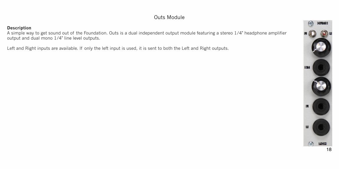
Outs Module!Description A simple way to get sound out of the Foundation. Outs is a dual independent output module featuring a stereo 1/4" headphone amplifier output and dual mono 1/4" line level outputs. Left and Right inputs are available. If only the left input is used, it is sent to both the Left and Right outputs. !!!!!!!!!!!!!!!!!!
�18
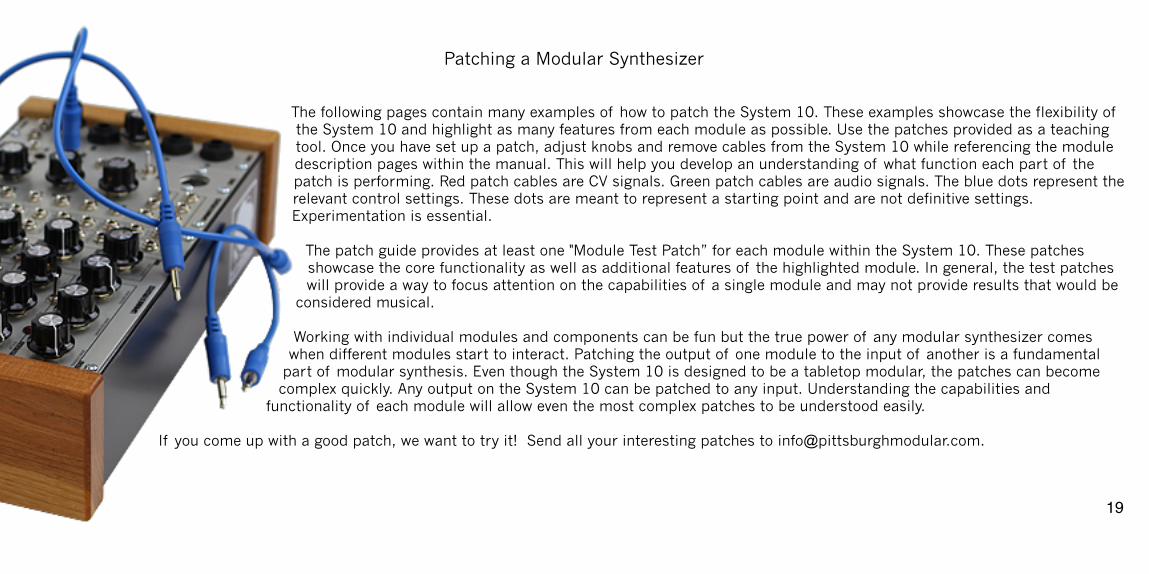
Patching a Modular Synthesizer! !The following pages contain many examples of how to patch the System 10. These examples showcase the flexibility of the System 10 and highlight as many features from each module as possible. Use the patches provided as a teaching tool. Once you have set up a patch, adjust knobs and remove cables from the System 10 while referencing the module description pages within the manual. This will help you develop an understanding of what function each part of the patch is performing. Red patch cables are CV signals. Green patch cables are audio signals. The blue dots represent the relevant control settings. These dots are meant to represent a starting point and are not definitive settings. Experimentation is essential. !
The patch guide provides at least one "Module Test Patch” for each module within the System 10. These patches showcase the core functionality as well as additional features of the highlighted module. In general, the test patches will provide a way to focus attention on the capabilities of a single module and may not provide results that would be
considered musical. !Working with individual modules and components can be fun but the true power of any modular synthesizer comes
when different modules start to interact. Patching the output of one module to the input of another is a fundamental part of modular synthesis. Even though the System 10 is designed to be a tabletop modular, the patches can become complex quickly. Any output on the System 10 can be patched to any input. Understanding the capabilities and
functionality of each module will allow even the most complex patches to be understood easily. !If you come up with a good patch, we want to try it! Send all your interesting patches to [email protected]. !!
�19
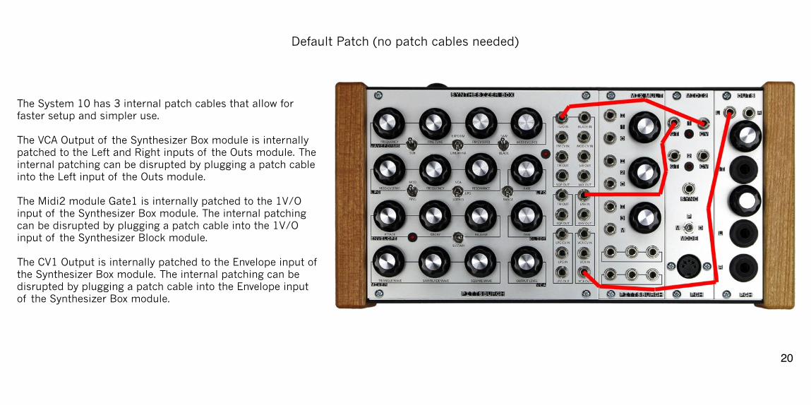
Default Patch (no patch cables needed) !!!The System 10 has 3 internal patch cables that allow for faster setup and simpler use. !The VCA Output of the Synthesizer Box module is internally patched to the Left and Right inputs of the Outs module. The internal patching can be disrupted by plugging a patch cable into the Left input of the Outs module. !The Midi2 module Gate1 is internally patched to the 1V/O input of the Synthesizer Box module. The internal patching can be disrupted by plugging a patch cable into the 1V/O input of the Synthesizer Block module. !The CV1 Output is internally patched to the Envelope input of the Synthesizer Box module. The internal patching can be disrupted by plugging a patch cable into the Envelope input of the Synthesizer Box module.
�20
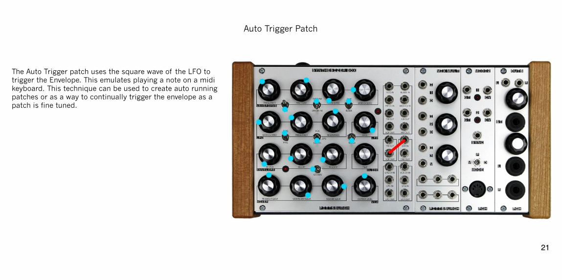
Auto Trigger Patch! !!The Auto Trigger patch uses the square wave of the LFO to trigger the Envelope. This emulates playing a note on a midi keyboard. This technique can be used to create auto running patches or as a way to continually trigger the envelope as a patch is fine tuned. !!!!!!!!!!!!!!!
�21
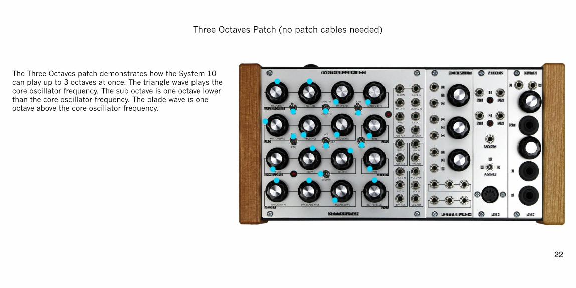
Three Octaves Patch (no patch cables needed)!!!!The Three Octaves patch demonstrates how the System 10 can play up to 3 octaves at once. The triangle wave plays the core oscillator frequency. The sub octave is one octave lower than the core oscillator frequency. The blade wave is one octave above the core oscillator frequency. !!!!!!!!!!!!!!!
�22
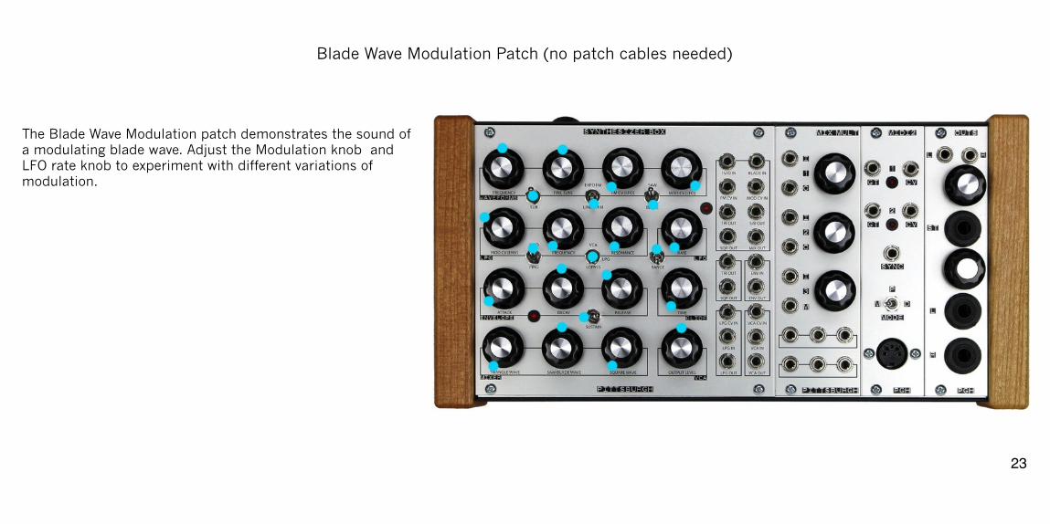
Blade Wave Modulation Patch (no patch cables needed)!!!!The Blade Wave Modulation patch demonstrates the sound of a modulating blade wave. Adjust the Modulation knob and LFO rate knob to experiment with different variations of modulation. !!!!!!!!!!!!!!!!
�23
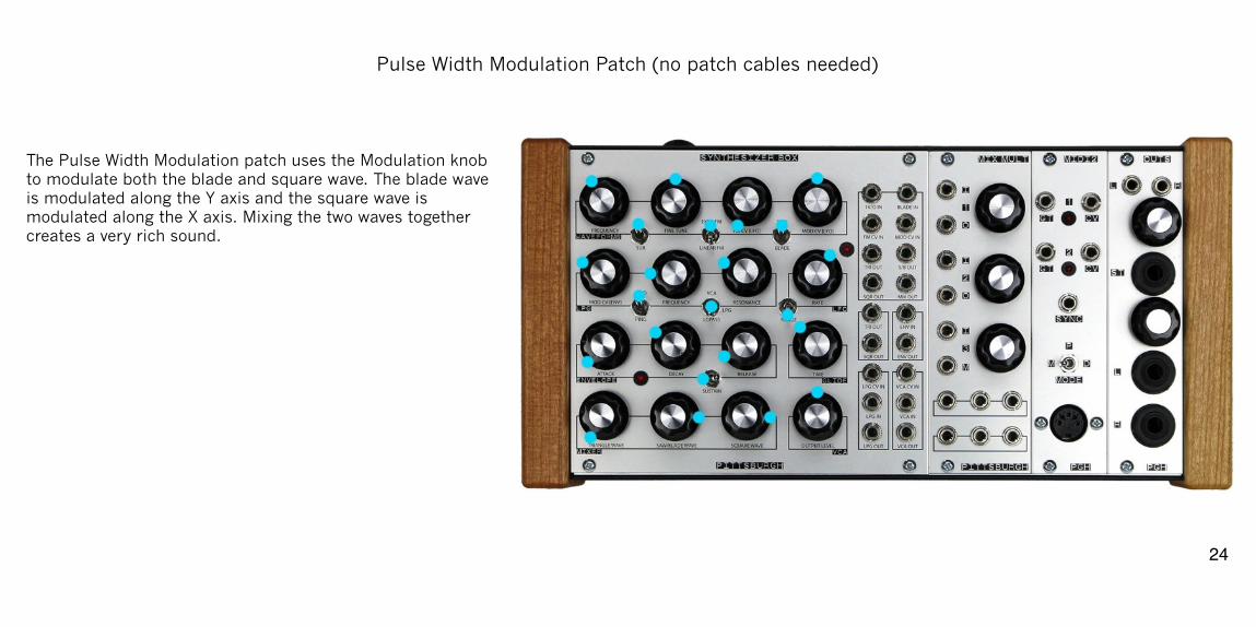
Pulse Width Modulation Patch (no patch cables needed)! !!The Pulse Width Modulation patch uses the Modulation knob to modulate both the blade and square wave. The blade wave is modulated along the Y axis and the square wave is modulated along the X axis. Mixing the two waves together creates a very rich sound. !!!!!!!!!!!!!!!
�24
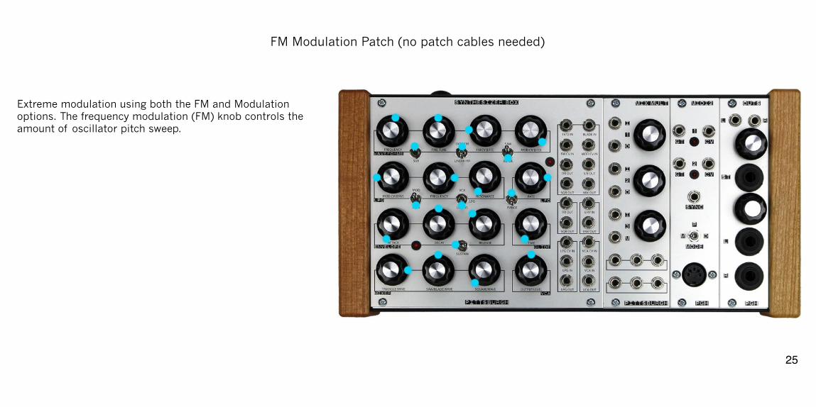
FM Modulation Patch (no patch cables needed)! !!Extreme modulation using both the FM and Modulation options. The frequency modulation (FM) knob controls the amount of oscillator pitch sweep. !!!!!!!!!!!!!!!!!
�25
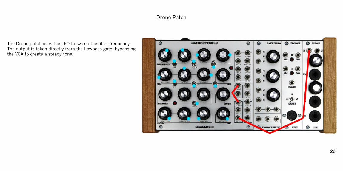
Drone Patch! !!The Drone patch uses the LFO to sweep the filter frequency. The output is taken directly from the Lowpass gate, bypassing the VCA to create a steady tone. !!!!!!!!!!!!!!!!!
�26
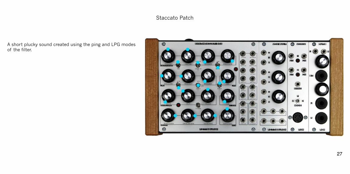
Staccato Patch! !!A short plucky sound created using the ping and LPG modes of the filter. !!!!!!!!!!!!!!!!!!
�27
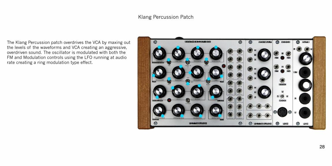
Klang Percussion Patch! !!The Klang Percussion patch overdrives the VCA by maxing out the levels of the waveforms and VCA creating an aggressive, overdriven sound. The oscillator is modulated with both the FM and Modulation controls using the LFO running at audio rate creating a ring modulation type effect. !!!!!!!!!!!!!!!
�28
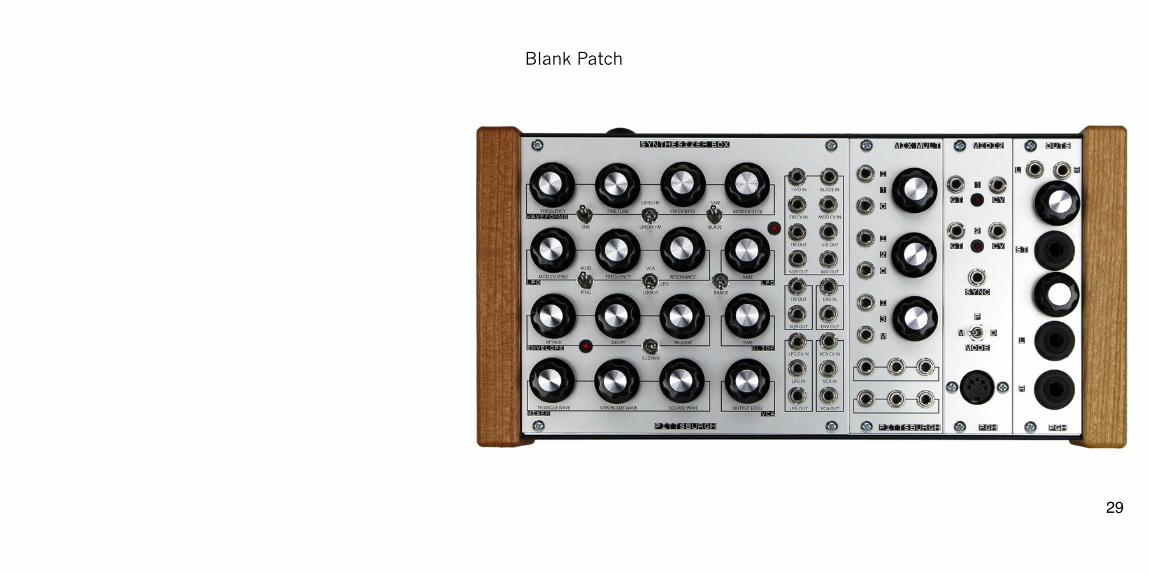
Blank Patch! !!!!!!!!!!!!!!!!!!!!!!
�29
Warranty!!!!1 Year Limited Warranty:
For a period of one year after the date of original purchase, the instrument and all factory installed parts and modules manufactured by Pittsburgh Modular Synthesizers LLC, are warranted to function properly and be free of defects in materials and workmanship. Should a factory installed module fail during the warranty period, contact Pittsburgh Modular Synthesizers LLC. We will repair it (or at our option, replace it) at no charge, and pay the cost of shipping it back to you.
The case and all case related hardware are warranted to function properly and be free of defects in materials and workmanship for 1 year.
Patch Cables are not covered by the 1 Year Limited Warranty.
This warranty is void if in our opinion the instrument has been damaged by accident, mishandled, altered, improperly serviced, or repaired by the customer where such treatment has affected its performance or reliability. This includes but is not limited to damage related to incorrectly attaching power ribbon cables. In the event of such misuse/abuse by the customer, costs for repairs plus two-way shipping costs will be borne by the customer. Instruments found defective should be returned to the factory carefully packed, as the customer will be responsible for freight damage.
Incidental or consequential damages or costs incurred as a result of product malfunction are not the responsibility of Pittsburgh Modular Synthesizers LLC. !!!�30
Service and Contact Information!!!!!!!Please contact us for service or other information.
www.pittsburghmodular.com/contact !!!!!!!!�31
Pittsburgh Modular Synthesizers!!!!!!!!!!!!! ! !!!Copyright 2014 Pittsburgh Modular Synthesizers LLC
�32


![MFD System Service Semantic Model and Service Interfaceftp.pwg.org/pub/pwg/candidates/cs-sm20-system10-20120217-5108.… · 16 extends the original PWG Semantic Model v1 [PWG5105.1]](https://img.pdfslide.us/doc/110x75/5ecf176e71cd98658b24fbd9/mfd-system-service-semantic-model-and-service-16-extends-the-original-pwg-semantic.jpg)