Embed Size (px)
Citation preview

Valves
Manual and motorized
butterfly valvesEBV-M & EBV-CMAP (E1305 rev. 02 - 07/04/2011)

EBV-M & EBV-CMAP - E1305 rev. 02 - 07/04/11
www.esapyronics.com 2
GENERAL WARNINGS:
¾¾ All installation, maintenance, ignition and setting mustbe performed by qualified staff, respecting the norms
present at the time and place of the installation.
¾¾ To avoid damage to people and things, it is essentialto observe all the points indicated in this handbook. The
reported indications do not exonerate the Client/User
from observing general or specific laws concerning acci-
dents and environmental safeguarding.
¾¾ The operator must wear proper DPI clothing (shoes,helmets...) and respect the general safety, prevention
and precaution norms.
¾¾ To avoid the risks of burns or high voltage electrocu-tion, the operator must avoid all contact with the burner
and its control devices during the ignition phase and
while it is running at high temperatures.
¾¾ All ordinary and extraordinary maintenance must beperformed when the system is stopped.
¾¾ To assure correct and safe use of the combustionplant, it is of extreme importance that the contents of this
document be brought to the attention of and be meticu-
lously observed by all personnel in charge of controlling
and working the devices.
¾¾ The functioning of a combustion plant can be dange-rous and cause injuries to persons or damage to equip-
ment. Every burner must be provided with certified com-
bustion safety and supervision devices.
¾¾ The burner must be installed correctly to prevent anytype of accidental/undesired heat transmission from the
flame to the operator or the equipment.
¾¾ The performances indicated in this technical docu-ment regarding the range of products are a result of
experimental tests carried out at ESA-PYRONICS. The
tests have been performed using ignition systems, flame
detectors and supervisors developed by ESA-PYRO-
NICS. The respect of the above mentioned functioning
conditions cannot be guaranteed if equipment, which is
not present in the ESA-PYRONICS catalogue, is used.
CERTIFICATIONS:
ASSISTANCE/CONTACTS:
To dispose of the product, abide by the local legislations
regarding it.
DISPOSAL:
Headquarters:Esa S.p.A.
Via Enrico Fermi 40
24035 Curno (BG) - Italy
Tel +39.035.6227411
Fax +39.035.6227499
International Sales:Pyronics International s.a.
Zoning Industriel, 4ème rue
B-6040 Jumet - Belgium
Tel +32.71.256970
Fax +32.71.256979
www.esapyronics.com
Conforms to the 2014/35/UE (low voltage) Directive.
GENERAL NOTES:
¾¾ In accordance to the internal policy of constant quali-ty improvement, ESA-PYRONICS reserves the right to
modify the technical characteristics of the present docu-
ment at any time and without warning.
¾¾ It is possible to download technical sheets whichhave been updated to the latest revision from the
www.esapyronics.com website.
¾¾ The products manufactured by ESA-PYRONICShave been created in conformity to the UNI EN 746-2:2010 Norms: Equipment for industrial thermal process
- Part 2: Safety requirements for combustion and the
movement and treatment of combustible elements. This
norm is in harmony with the Machine Directive
2006/42/CE. It is certified that the products in question
respect all the requirements prescribed by the above
mentioned Norms and Directives.
¾¾ Certified in conformity with the UNI EN ISO 9001Norm by DNV GL.
The products conform to the requests for the Euroasia market
(Russia, Belarus and Kazakhstan).

EBV-M & EBV-CMAP - E1305 rev. 02 - 07/04/11
www.esapyronics.com 3
APPLICATIONS
The EBV butterfly valve series are suitable for the adju-
stment of cold or hot air flow in low pressure ducts.
¾¾Air and fume flow adjustment.
¾¾Air interception.
¾¾Air and fume partializing.
¾¾Manual control or with electric motor unit.
CHARACTERISTICS
VALVE:
¾¾Maximum working pressure: 210 mbar
¾¾Maximum fluid temperature: 450°C
¾¾Drawing capacity with closed valve: about 2%
¾¾Available sizes: from DN65 PN16 to DN150 PN16
¾¾Coupling flanges: excluded
¾¾Flange gaskets: excluded
ELECTRIC MOTOR UNIT:
¾¾Model: ECON-O
¾¾Couple: 20Nm (opzioni 4Nm/7Nm/15Nm)
¾¾Voltage supply: 24/115/230Vac +10 ÷ -5%
¾¾Frequency supply: 50 ÷ 60Hz
¾¾Command signal: open/close or proportional
¾¾Proportional command type: 0-10V 4-20mA (only for ECON-O 24 Vac)
¾¾Functioning temperature: -10°C ÷ +60°C
¾¾Storage temperature: -20°C ÷ +80°C
¾¾Absorbtion: 7VA
¾¾n° 2 auxiliary switch flow: 5A/250Vac
¾¾Feedback resistor open/close mod.:nr.1 1000 Ohm
(options 150 Ohm/1000 Ohm/2500 Ohm)
¾¾Feedback signal proportional mod.: 0-10Vdc
¾¾Rotation angle: 90°
¾¾Rotation period at 90°: 60 sec.(options from 7 sec. to 120 sec.)
¾¾Lever shaft connection: panel 9,5 mm
¾¾Control station AUTO-MAN: included
¾¾Protection degree: IP54
¾¾Mass: 2,5 Kg
¾¾Electric cable inlet: nr. 2 threaded inlets PG 13,5
¾¾Mounting position: any
¾¾Work environment: Not appropriate in explosive or corrosive environments
MATERIAL COMPOSITION:
¾¾Valve body: Cast iron G40
¾¾Lens holder shaft: AISI316
¾¾Valve disc: AISI304
¾¾Manual activation lever: aluminium (M version)
¾¾Motor unit case: die-cast aluminium
¾¾Motor unit support plate: Fe360
¾¾Motor unit coupling rod: Fe360
F130503
F130504
EBV-M
EBV-CMAP
¾¾Valve command lever: brass (CMAP version)
¾¾Surface treatment zinc coated

20EBV
24EBV
32EBV
48EBV
1
10
100
100 1.000 10.000
EBV-M & EBV-CMAP - E1305 rev. 02 - 07/04/11
www.esapyronics.com 4
DESCRIPTION
The EBV butterfly valve series is subdivided into two cate-
gories: manual valves that can be identified with the suf-
fix M and automatic valves with an electric motor unit,
identifiable with suffix CMAP. The EBV-M valves have
been created to facilitate the use by the operator. They
are composed of a butterffly valve body and a manual
lever placed on top, including an opening block device in
various positions. The EBV-CMAP are used in automatic
applications in which the opening and closing of the but-
terfly element is comtrolled by an electric motor unit. The
motor unit is mounted on a support plate and is connec-
ted to the valve stem by a jointed lever system, adjusta-
G130501
FLOW CHART
EBV valves must be chosen according to their desi-red use: the valve used as an interception devicemust have the same diameter as the pipe, meanwhi-
Air flow @ 20 °C P.S.= 1 [Nm3/h]
Charg
e loss [
mbar]
ble rods and couplings, for better calibration according to
the the application needs. The holes in the support plate
allow the mounting of various types of motor units if the
ECON-O model is not applicable. ESA-PYRONICS sup-
plies the EBV-CMAP valves with ECON-O motor units
which are predisosed for an adjustment of 0 ÷ 90°. All the
motor units have a manual command station, two auxilia-
ry switches set at 10° and 80° and a signal for the feed-
back of the point reached. In particular, for the models
with the open/close command, feedback takes place via
an ohm resistor. While in the models with the proportional
command a similar signal is available in volts.
le if it is used as an adjustement organ, it must gua-rantee a charge which is compatible with an adequa-te adjustment.

EBV-M & EBV-CMAP - E1305 rev. 02 - 07/04/11
www.esapyronics.com 5
WARNINGS
¾¾Make sure that the working pressure and the fluidtemperature are lower than the maximum allowed
values.
¾¾The EBV series valves are supplied without couplingflanges or gaskets. The flanges and gaskets to be
applied must be suitable for the type of valve and its
application.
¾¾Check the correct installation of the valve before star-ting the flow in the pipeline.
¾¾Check the correct electric connections. Before activa-ting the electric supply to the motor unit, make sure that
the volatge, frequency and command signal are correct.
Check that the users’ absorption is not higher than the
maximum flow of the auxiliary switch contacts.
¾¾The motor unit is intended to be electrically connectedon a permanent basis. Inverting the connection
phase/neutro can compromise the safety of the system.
Do not use different phases among the various voltage
inlets and do not apply voltage on the outlet clamps.
¾¾Intervene on the motor unit and its connected devicesonly in the absence of volatge supply (electric current
disconnected). Number the conductors before discon-
necting the device.
¾¾To avoid damaging the internal adapter, do not rotatethe motor unit shaft neither by forcing the lever nor with
tools.
¾¾In case of valve or motor unit malfunctioning, followthe instructions in the “MAINTENANCE” chapter of the
present manual, or contact ESA-PYRONICS assistance
service.
¾¾Any modification or repair done by third parties maycompromise the application safety and will automatically
cause the general warrantee conditions to expire.

EBV-M & EBV-CMAP - E1305 rev. 02 - 07/04/11
www.esapyronics.com 6
INSTALLATION
To install, carefully follow the instructions below:
ASSEMBLY
1 - Arrange the EBV valves far from excessive heat sour-
ces and products such as: liquids, solvents or corrosive
gases.
2 - The valve (pos. 01) can be installed in any position.
Maintain a certain distance from the surrounding ele-
ments allowing air to circulate freely.
3 - Check that the flanges (pos. 02), gaskets (pos. 04)
and pipes (pos. 03) are compatible with with the valve
and fluid.
4 - Check the correct alignment of the pipe fittings and
check the correct distance between the pipes and the
assembly (flanges/gaskets/valve body), to avoid exerting
tension on the pipes during the tightening phase.
5 - Weld the flanges (pos.2) at the ends of the pipes, eli-
minating possible welding dribbles.
6 - Make sure that there are no foreign objects inside the
valve or in the pipes before proceeding to assemble. If
necessary remove the impurities.
7 - Position the valve between the two flanges (pos. 04),
bolts (pos.05), washers and nuts (pos. 06).
8 - Using appropriate instruments, progressively screw
the bolts on crossing them over each other, avoiding
excessive tightening.
ELECTRICAL CONNECTION
1 - Check that the motor unit is compatible with the con-
trol system, both for voltage supply as well as for the
type of command.
2 - Use the inlets that have already been placed on the
motor unit for the passage of the electric cables, without
making other holes in the case. Install cable glands or
03
03
05
04
04
01
02
02 06
D130501
conduit fittings made to warrantee a protection degree
equal or not inferior to IP40. For systems used in open
air the minimum protection degree must be equal to
IP54. The degree of protection can also be guaranteed
by the container in which the device has been inserted.
3 - The command signal cable of the proportional motor
unit must be screened and the drafting must be done
separately from the power supply lines, the motor con-
trols (inverter) and the network voltage; in particular,
multipole cables must not be used.
4 - If the power feed system is a phase-phase type, it is
necessary to install an insulating transformer with a
secondary earthing connection.
5 - When connecting the electricity refer to the technical
documentation, respecting the polarity between phase
and neutral. The electrical connection clamps are screw
on type and can accept section conductors from 0.5 to
2.5mm²; the choice of conductors and their location
must be suitable for the application. The numbering and
the use of appropriate terminals on these conductors is
suggested.
6 - Always make sure that the earthing protection is con-
nected to the relative clamps and to the motor unit box
by conductors with appropriate sections.
7 - After the connection procedure make sure that the
conductors do not interfere internally with the motor unti-
t’s gear system. Close the lid, checking the correct posi-
tion of the gasket and verifying that the conductors do
not remain squashed between the lid and the box.
F130505

EBV-M & EBV-CMAP - E1305 rev. 02 - 07/04/11
www.esapyronics.com 7
OPEN
CLOSED
2
1
D130502
OPEN
CLOSED
1
2
3
54
7
6
D130503
ADJUSTMENT - SETTING
The operations indicated in the following chapter must be
carried out by technically qualified and expert staff.
During the adjustment phase monitor the pipe flow using
flow measurement devices (calibrated flanges, differen-
tial pressure gauges, etc...)
EBV-M VALVE
The adjustment and setting of the EBV-M manual valves
takes place using, as a reference, the dented metallic
disc placed under the adjustment lever, on which the
opening and closing limits are indicated.
1 - Grip the handle (pos. 01) placed on top of the valve
and lift the arm underneath so as to unhook the block
device from the dented disc (pos. 02).
2 - Rotate the lever (pos. 01) until reaching the new
desired adjustment position. The rotation angle of the
valve is 90° and when the lever in in the transversal
position compared to the piping, the valve is CLOSED.
Otherwise, when it is in the longitudinal position compa-
red to the piping the valve is OPEN.
3 - Let go of the arm underneath the lever (pos. 01),
checking that the block device hooks onto the dented
disc (pos. 02), blocking the valve in its new position.
4 - If more than one valve is adjusted on a shunt from
the same pipe, at the end of the adjustment procedure,
check the setting of the first valves to make sure it has
not altered. Otherwise re-adjust them again.
EBV-CMAP VALVE
The adjustment and setting of the motorized EBV-CMAP
valves defines the minimum and maximum opening of
the valve controlled by the motor unit. The two limit posi-
tions of the valve movement must correspond to the mini-
mum and maximum flow desired in the case of an adju-
stment valve, whilst in the case of an interception valve
(factory adjustment) the limit positions must correspond
to open or closed valve. Adjustment takes place by
varying the rotation angle of the valve compared to the
motor unit, acting on levers and return joints. The reduc-
tion of the motor unit’s stroke is not advised for models
with open/close command and is not possible for propor-
tional motor units.
1 - Open the lid of the motor unit to get access to the
manual command station. Place the AUTO/MAN com-
mutator in the manual position indicated with the hand
A (see pag. 8), and then supply electrical connection to
the motor unit.
2 - Place the OPEN/CLOSE switch on the q symbol(closed), so that the shaft rotates in the clockwise direc-
tion allowing the valve to close completely. The S1 cam
defines the closing position limit.
3 - Loosen the rod locking grain which is placed on the
valve joint (pos. 05). Manually adjust the minimum ope-
ning of the valve making the rod slide (pos. 03) inside
the joint moving the valve through its appropriate jointed
lever (pos. 04) obtaining the minimum flow requested.
At the end fasten the locking grain.
4 - Place the OPEN/CLOSE switch on the p symbol(open), so that the shaft rotates in the anticlockwise
direction allowing the valve to open completely. The S2
cam defines the opening position limit. Check the adju-
sted flow rate of the valve during the passing from mini-
mum to maximum opening positions.

EBV-M & EBV-CMAP - E1305 rev. 02 - 07/04/11
www.esapyronics.com 8
A
5 - Consider the adjustment made by the valve on the
flow: if the maximum flow rate has been reached before
the motor unit gets to the maximum opening, the valve
stroke must be reduced, otherwise it must be increased.
6 - Put the valve back to the minimum opening position
(see point 2) until the motor unit stops working.
7 - Change the position of the joints (pos. 02 and pos.05) making them slide into the appropriate jointed levers
(pos. 01 and pos. 04). To decrease the valve stroke
compared to the motor unit it is necessary to bring the
joint (pos. 02) closer to the motor unit pivot (pos. 06), or
move the joint (pos. 05) away from the valve pivot (pos.07). The difference between the two actions is that, with
equal displacement, the one carried out on the jointed
lever motor unit (1) changes the valve opening angle the
most.
8 - Adjust the minimum opening again according to the
description in point 3.
9 - Check the new adjustment of the valve repeating the
operations indicated between step 4 and 8 until obtaining
the requested flow regulation.
10 - Place the AUTO/MAN commutator on the automatic
position checking that the motor unit respects the syste-
m’s control commands. Finally, close the lid again, chec-
king the correct positioning of the gasket and making
sure that the conductors do not remain squashed betwe-
en the lid and the box.
The ECON-O motor units are supplied by the factory
already prepared for a 90° rotation, with the S3 and S4
auxiliary switches respectively adjusted at 10° (S3 mini-
mum opening) and 80° (S4 maximum opening).
For the open/close motor units the resistor is prepared
for a 90° angle rotation. If the motor unit’s rotation angle
is reduced, the resistance variation will be proportionally
reduced, whereas if the angle is increased, there will be
no further increase of the resistance. For the motor units
that have a proportional command, all calibrations have
already been set by the factory and therefore any inter-
vention on the cam limits (S1 e S2) and resistor is unad-
visable. To adjust the S3 and S4 auxiliary switches follow
the following indications:
1 - Open the motor unit lid to get access to the manual
command station. Place the AUTO/MAN commutator on
the manual position indicated with hand A.
2 - Via the OPEN/CLOSE switch place the valve in the
desired position, corresponding to the activation of the
auxiliary switch.
3 - Adjust the auxiliary switches’ cam using the straight
part of the special lever: insert the rod in one of the holes
situated on the sides of the mobile corona of the cam
and drag it to the desired position. If the mobile corona
is in a completely withdrawn position, use the curved
part of the lever to drag it into a more suitable position for
adjustment.
4 - Take the lever away before starting the motor unit. Via
the OPEN/CLOSE switch move the motor unit, checking
that the activation of the auxiliary switch is in the correct
position.
5 - Finally place the AUTO/MAN commutator in the auto-
matic position and close the lid again, checking the cor-
rect positioning of the gasket and the conductors.
F130506

EBV-M & EBV-CMAP - E1305 rev. 02 - 07/04/11
www.esapyronics.com 9
For a correct maintenance of the EBV valves, scrupulou-
sly follow the instructions given below. Before carrying
out any manouvre with the plant on, make sure that the
process saftey as well as that of the operator are in no
way compromised, or else check and verify with the plant
turned off.
INTEGRITY CHECK
¾¾ The integrity of the gaskets can be checked visually.if the use of leak dector liquids is necessary, it is possi-
ble to check only if the flow inside the conductor is cold
and in low pressure.
¾¾ The integrity of the electric cables can be checkedvisually. If it is necessary to operate on the conductors,
not being totally visible, disconnect the power feed to the
device before carrying out any type of operation. Before
replacing the motor unit, make sure that the actual motor
unit is in fact the cause of the malfunctioning.
VALVE MOVEMENT
¾¾ The test to see that there is nothing hindering thevalve movement takes place by carrying out a complete
excursion, visually checking that there are neither fric-
tion nor stroke limitations. If the valve is for air or fume
interception, before carrying out the operation, turn the
connected burners off.
GENERAL MAINTENANCE PLAN
ORDINARY MAINTENANCE
OperationType(*)
SuggestedSchedule
Notes
Gasket integrity O annualCheck that there are no air or fume leaks
towards the outside.
Bolt fixing S annualIn case there are vibrations, reduce to a half
- yearly application.
Motor unit cable connection integrity O half yearly
Check the external insulation integrity as well
as the absence of abrasions or the
overheating of conductors.
Valve movement O/S half yearlyCheck the absence of hindrance of the
valve movement.
Valve adjustment O/S annualCheck the flow adjustment carried out by the
valve.
Electric motor unit O/S annual
Check that the commands are respected and
that the auxiliary switches and the feedback
signals are correct.
Maintenance of the butterfly valve S annualCheck the state of the internal elements of the
valve.
NOTES:
Caption: O = ordinary / S = extraordinary
(*) it is advised that you replace the gaskets after everytime you disassemble the valve.
VALVE ADJUSTMENT - ELECTRIC MOTOR UNIT
¾¾ Check with burners off but with flow present in theduct. Check that the adjustment made by the valve is
correct, if necessary repeat all the steps in the “ADJU-
STMENT - SETTING” chapter.
¾¾ The motor unit must be checked when the burnersare off and can be done with or without flow. Make sure
that the commands sent by the control system are car-
ried out by the motor unit and that the feedback position
and auxiliary switch signals send the control system cor-
rect indications. If necessary repeat all the steps in the
“ADJUSTMENT - SETTING” chapter.

EBV-M & EBV-CMAP - E1305 rev. 02 - 07/04/11
www.esapyronics.com 10
For a correct maintenance of the EBV valves, scrupulou-
sly follow the following instructions that are to be carried
out with the plant off.
BOLT TIGHTENING
¾¾ Bolt tightening must be checked when the plant is offand cold.
BUTTERFLY VALVE MAINTENANCE - GASKETREPLACEMENT
1 - Close the interception valve upstream the piping and
make sure there is no flow in the duct.
2 - Place the valve in the completely closed position,
otherwise it will not be possible to extract the piping.
3 - Progressively unscrew the screws which fix the valve
in a crossed position. Extract the valve and check the
state of the internal components.
4 - Clean the inside of the valve body and the butterfly
group with a clean cloth and compressed air. Do not use
tools that could damage the internal parts.
5 - Check the correct tightening of the butterfly fixing
screws on the lens holder shaft.
6 - Make sure that the butterfly moves freely without fric-
tion. If necessary lubricate with mineral oil which is suita-
ble for high temperatures.
7 - Replace the gaskets and reassemble the valve in its
place, following the steps indicated in the “INSTALLA-
TION” section.
8 - Finally check that the valve moves freely without hin-
drance.
9 - Check that the adjustment carried out by the valve is
correct, if necessary repeat all the steps indicated in the
“ADJUSTMENT - SETTING” chapter.
EXTRAORDINARY MAINTENANCE
MOTOR UNIT REPLACEMENT
1 - Make sure the motor unit is indeed the cause of mal-
functioning and check that you have a spare unit motor
which is the same as the one that needs replacing.
2 - Disconnect electric supply, remove the lid of the
motor unit and then disconnect all electric connections
from the clamp. Extract the conductors from their case
being careful not to damage them.
3 - Unhook the jointed lever (pos. 01) from the motor unit
rod (pos. 06) without loosening the joint adjustments
(pos. 02 and pos.05), so that afterwards the adjustment
operations are facilitated (rod position of motor unit con-
stant).
4 - Remove the motor unit fixing screws of the support
plate and remove it.
5 - Secure the new motor unit onto the support plate,
reconnect the jointed lever (pos. 01) to the motor unit
rod (pos. 06) paying attention not to erroneously place
the butterfly opening indicator.
6 - Reinsert the conductors back into the motor unit case
and connect them to the clamp referring to the electric
wiring diagram.
7 - Make sure that the commands sent by the control
system are carried out by the motor unit and that the
feedback position and auxiliary switch signals send the
control system correct indications. If necessary repeat all
the steps in the “ADJUSTMENT - SETTING” chapter.

EBV-M & EBV-CMAP - E1305 rev. 02 - 07/04/11
www.esapyronics.com 11
OVERALL DIMENSIONS - EBV-M"D
"
"E"
"C"
"F"
DN "A"
Ø"B"
Model DN “A” Ø “B” “C” “D” “E” “F”Masskg
20EBV DN65 122 60 154 313 40 3
24EBV DN80 138 68 174 313 40 3.6
32EBV DN100 158 81 184 313 46 4.95
48EBV DN150 212 110 204 313 54 6.95
D130504
Model DN “A” Ø “B” “C” “D” IS “E” “F” “G”Masskg
20EBV-CMAP DN65 122 60 160 295 40 150 6.5
24EBV-CMAP DN80 138 68 180 295 40 150 7.1
32EBV-CMAP DN100 158 81 190 405 46 260 8.45
48EBV-CMAP DN150 212 110 210 405 54 260 10.7
OVERALL DIMENSIONS - EBV-CMAP
"F"
DN "A"
Ø"B"
"D"
"C"
"E" 150
"G"
15
0
10
3
124
D130505
EBV-M & EBV-CMAP - E1305 rev. 02 - 07/04/11
www.esapyronics.com 12
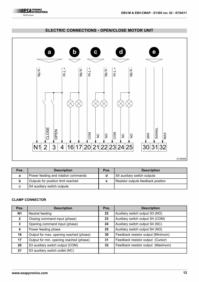
ELECTRIC CONNECTIONS - OPEN/CLOSE MOTOR UNIT
20N1 1716432
CL
OS
E
OP
EN
31302524232221
Mp
N -
Ph
L +
32
Mp
N -
Ph
L +
Mp
N -
Ph
L +
Mp
N -
NC
CO
M
NO
NC
CO
M
NO
SIG
NA
L
MIN
MA
X
a b c d e
D130506
Pos. Description
a Power feeding and rotation commands
b Outputs for position limit reached
c S4 auxiliary switch outputs
Pos. Description
d S4 auxiliary switch outputs
e Resistor outputs feedback position
Pos. Description
22 Auxiliary switch output S3 (NO)
23 Auxiliary switch output S4 (COM)
24 Auxiliary switch output S4 (NC)
25 Auxiliary switch output S4 (NO)
30 Feedback resistor output (Minimum)
31 Feedback resistor output (Cursor)
32 Feedback resistor output (Maximum)
Pos. Description
N1 Neutral feeding
2 Closing command input (phase)
3 Opening command input (phase)
4 Power feeding phase
16 Output for max. opening reached (phase)
17 Output for min. opening reached (phase)
20 S3 auxiliary switch output (COM)
21 S3 auxiliary switch outlet (NC)
CLAMP CONNECTOR

EBV-M & EBV-CMAP - E1305 rev. 02 - 07/04/11
www.esapyronics.com 13
ELECTRIC CONNECTIONS - PROPORTIONAL MOTOR UNIT
a b c d e
201 432
INP
UT
2524232221
Ph
L +
Mp
N -
Ph
L +
Mp
N -
NC
CO
M
NO
NC
CO
M
NO
OU
TP
UT
Ph
L +
Mp
N -
24
Va
c
0 V
ac
+ IN
- IN
+ O
UT
- O
UT
4140P
h L
+
Mp
N -
f
D130507
Pos. Description
a Power 24Vac
b Analogical comand signal
c Analogical reverse action signal
Pos. Description
d S3 Auxiliary limit switch output
e S4 Auxiliary limit switch output
f Power feed of optional internal transformer
Pos. Description
1 Power inlet of 24Vac
20Vac power feed inlet, negative analogical
comand signal and negative reverse action
analogical comand.
3 Positive analogical comand signal inlet
4 Positive reverse action analogical comand outlet
20 Auxiliary limit switch output S3 (COM)
21 Auxiliary limit switch output S3 (NC)
Pos. Description
22 Auxiliary limit switch output S3 (NO)
23 Auxiliary limit switch output S4 (COM)
24 Auxiliary limit switch output S4 (NC)
25 Auxiliary limit switch output S4 (NO)
40Power feed phase of optional internal
transformer
41 Neutral of optional internal transformer
CONNECTING CLAMPS

EBV-M & EBV-CMAP - E1305 rev. 02 - 07/04/11
www.esapyronics.com 14
OVERALL DIMENSIONS - MOTOR UNIT
115
85
14
3
152
166
0
180
90
200
50
50
9,5
17
12
17
2xPg13,5
12
4
7
103.3
126
183
14
4
POWER END
D130508

EBV-M & EBV-CMAP - E1305 rev. 02 - 07/04/11
www.esapyronics.com 15
ORDERING INITIALS - EBV
EBV- --
Model
DN65
DN80
DN100
DN150
20243248
Type
Manual
Automatic with motor unit
MCMAP
Motor unit voltage feed
24Vac 50÷60Hz
115Vac 50÷60Hz
230Vac 50÷60Hz
24V115V230V
01
01 02 03-
04
02 (*)Command TypeProportional (only 24V)
In current
In voltage
4-20mA0-10V
04
03
(*) Not applicable for models wth open/close command.