Embed Size (px)
Citation preview
Type 99
D10
0260
X01
2
Instruction ManualForm 589
February 2016
www.fisherregulators.com
Type 99 Pressure Reducing Regulator
Introduction
Scope of the ManualThis manual describes and provides instructions for installation, startup, adjustment and parts ordering information of Type 99 pressure reducing regulator complete with standard P590 Series integral fi lter. Information on other equipment used with this regulator can be found in separate manuals.
Figure 1. Type 99 Regulator with Type 61H (High Pressure) Pilot
W2676
! WARNINg
Since a pilot-operated regulator is constructed of both a pilot and a main valve, care should be used not to exceed the maximum inlet pressure shown on the nameplate of either unit. When inlet pressure exceeds the pilot limitation, a pilot supply reducing regulator and/or relief valve is required.
! WARNINg
Failure to follow these instructions or to properly install and maintain this equipment could result in an explosion and/or fi re causing property damage and personal injury or death.
Fisher® regulators must be installed, operated and maintained in accordance with federal, state and local codes, rules and regulations and Emerson Process Management Regulator Technologies, Inc. instructions.
If the regulator vents gas or a leak develops in the system, service to the unit may be required. Failure to correct trouble could result in a hazardous condition.
Call a gas service person to service the unit. Only a qualifi ed person must install or service the regulator.
Type 99
2
DescriptionThe Type 99 gas regulator provides a broad capacity for controlled pressure ranges and capacities in a wide variety of distribution, industrial and commercial applications.
A Type 99 regulator has a Type 61L, 61LE or 61LD (low pressure); Type 61H (high pressure); or Type 61HP (extra high pressure) pilot integrally mounted to the actuator casing as shown in Figure 1. The Type 99 regulator can handle up to 1000 psig / 69.0 bar inlet
pressure (the 1000 psig / 69.0 bar regulator requires a Type 1301F pilot supply regulator and a Type H110 pop relief valve). The pilot supply regulator reduces inlet pressure to a usable 200 psig / 14 bar for the extra high-pressure pilot. The standard Type 99 regulator comes with O-ring seals on the guide bushing and valve carrier to keep main valve body outlet pressure from interfering with outlet pressure in the lower casing assembly.
SpecificationsSpecifications and ratings for various Type 99 constructions are listed in the Specifications section below. Some specifications for a given regulator as it originally comes from the factory are stamped on the nameplates located on the pilot and actuator spring cases. An additional nameplate may be installed on the pilot to indicate a regulator with O-ring stem seal. These regulators and their installations should be checked for compliance with applicable codes.
1. The pressure/temperature limits in this Instruction Manual and any applicable standard or code limitation should not be exceeded. 2. For stability or overpressure protection, a pilot supply regulator may be installed in the pilot supply tubing between the main valve and pilot.
Available Constructions Type 99L - Type 99 with Type 61L pilot which
has 2 in. w.c. to 20 psig / 5 mbar to 1.4 bar pressure range
Type 99LD - Type 99 with Type 61LD pilot which has a narrower proportional band than the standard Type 61L pilot
Type 99LE - Type 99 with Type 61LE pilot which has a broader proportional band than the standard Type 61L pilot
Type 99H - Type 99 with Type 61H pilot which has 10 to 65 psig / 0.69 to 4.5 bar pressure range
Type 99HP - Type 99 with Type 61HP pilot has 35 to 100 psig / 2.4 to 6.9 bar pressure range
Body Size and End Connection StylesNPS 2 / DN 50 body with NPT, CL125 FF, CL150 RF, CL250 RF and CL300 RF end connections
Maximum Allowable Inlet Pressure(1)
160 psig / 11.0 bar: Type 61LD pilot400 psig / 27.6 bar: Type 61L, 61LE or 61H pilots 1000 psig / 69.0 bar: Type 61HP pilot, along withType 1301F pilot supply regulator and Type H110 relief valve (1/2 in. / 13 mm orifice only)
Outlet (Control) Pressure Ranges(1)
See Table 1
Approximate Proportional BandsSee Table 2
Maximum Allowable Pressure Drop(1)
See Table 3Maximum Actuator Pressures(1)
Operating: 100 psig / 6.9 barEmergency: 110 psig / 7.6 bar
Maximum Pilot Spring Case Pressure for Pressure Loading(1)(2)
Types 61L, 61LD and 61LE: 50 psi / 3.4 bar with special steel closing capTypes 61H and 61HP: 100 psi / 6.9 bar
Minimum Differential Pressure Required for Full Stroke
See Table 3Maximum Rated Travel
1/4 in. / 6.4 mmTemperature Capabilities(1)
With Nitrile (NBR) / Neoprene (CR) / Nylon (PA): -20 to 180°F / -29 to 82°CWith Fluorocarbon (FKM): 0 to 300°F / -18 to 149°C
Type 99
3
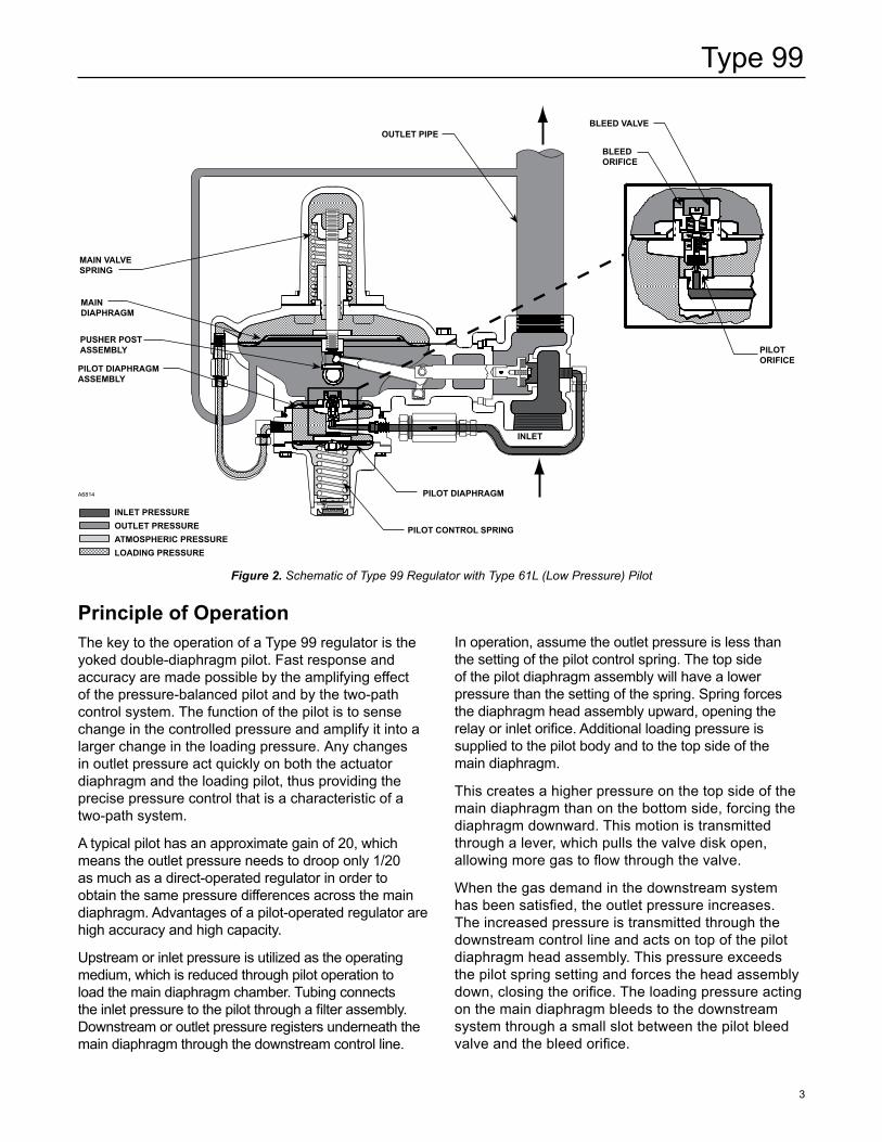
Figure 2. Schematic of Type 99 Regulator with Type 61L (Low Pressure) Pilot
A6814
OuTLET PIPE
PILOT ORIFICE
BLEED ORIFICE
BLEED vALvE
PILOT DIAPHRAgM ASSEMBLy
PuSHER POST ASSEMBLy
MAIN DIAPHRAgM
MAIN vALvE SPRINg
PILOT CONTROL SPRINg
PILOT DIAPHRAgM
INLET
INLET PRESSuREOuTLET PRESSuREATMOSPHERIC PRESSuRELOADINg PRESSuRE
Principle of OperationThe key to the operation of a Type 99 regulator is the yoked double-diaphragm pilot. Fast response and accuracy are made possible by the amplifying effect of the pressure-balanced pilot and by the two-path control system. The function of the pilot is to sense change in the controlled pressure and amplify it into a larger change in the loading pressure. Any changes in outlet pressure act quickly on both the actuator diaphragm and the loading pilot, thus providing the precise pressure control that is a characteristic of a two-path system.
A typical pilot has an approximate gain of 20, which means the outlet pressure needs to droop only 1/20 as much as a direct-operated regulator in order to obtain the same pressure differences across the main diaphragm. Advantages of a pilot-operated regulator are high accuracy and high capacity.
Upstream or inlet pressure is utilized as the operating medium, which is reduced through pilot operation to load the main diaphragm chamber. Tubing connects the inlet pressure to the pilot through a filter assembly. Downstream or outlet pressure registers underneath the main diaphragm through the downstream control line.
In operation, assume the outlet pressure is less than the setting of the pilot control spring. The top side of the pilot diaphragm assembly will have a lower pressure than the setting of the spring. Spring forces the diaphragm head assembly upward, opening the relay or inlet orifice. Additional loading pressure is supplied to the pilot body and to the top side of the main diaphragm.
This creates a higher pressure on the top side of the main diaphragm than on the bottom side, forcing the diaphragm downward. This motion is transmitted through a lever, which pulls the valve disk open, allowing more gas to flow through the valve.
When the gas demand in the downstream system has been satisfied, the outlet pressure increases. The increased pressure is transmitted through the downstream control line and acts on top of the pilot diaphragm head assembly. This pressure exceeds the pilot spring setting and forces the head assembly down, closing the orifice. The loading pressure acting on the main diaphragm bleeds to the downstream system through a small slot between the pilot bleed valve and the bleed orifice.
Type 99
4
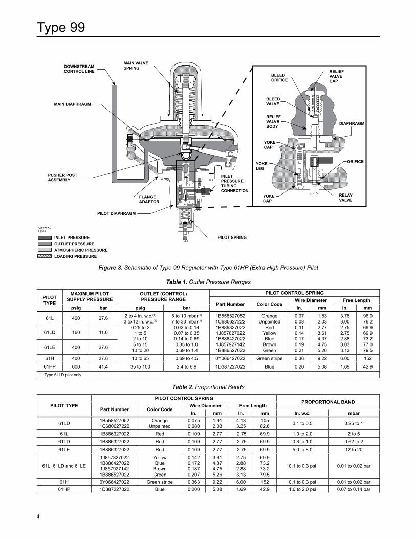
Figure 3. Schematic of Type 99 Regulator with Type 61HP (Extra High Pressure) Pilot
DOWNSTREAM CONTROL LINE
MAIN DIAPHRAgM
PuSHER POST ASSEMBLy
MAIN vALvE SPRINg
FLANgE ADAPTOR
PILOT DIAPHRAgM
INLET PRESSuRE TuBINg CONNECTION
PILOT SPRINg
RELIEF vALvE CAP
DIAPHRAgM
BLEED ORIFICE
BLEED vALvE
RELIEF vALvE BODy
yOKE LEg
yOKE CAP
yOKE CAP
RELAy vALvE
ORIFICE
54A2767-aA2505
INLET PRESSuREOuTLET PRESSuREATMOSPHERIC PRESSuRELOADINg PRESSuRE
PILOT TyPE
MAXIMuM PILOTSuPPLy PRESSuRE
OuTLET (CONTROL)PRESSuRE RANgE
PILOT CONTROL SPRINg
Part Number Color CodeWire Diameter Free Length
psig bar psig bar In. mm In. mm
61L 400 27.6 2 to 4 in. w.c.(1)
3 to 12 in. w.c.(1)
0.25 to 21 to 52 to 105 to 1510 to 20
5 to 10 mbar(1)
7 to 30 mbar(1)
0.02 to 0.14 0.07 to 0.35 0.14 to 0.69 0.35 to 1.0 0.69 to 1.4
1B5585270521C6806272221B8863270221J8578270221B8864270221J8579271421B886527022
OrangeUnpainted
RedYellowBlue
BrownGreen
0.07 0.08 0.11 0.140.170.190.21
1.832.032.773.614.374.755.26
3.783.00 2.75 2.75 2.883.033.13
96.076.269.969.973.277.079.5
61LD 160 11.0
61LE 400 27.6
61H 400 27.6 10 to 65 0.69 to 4.5 0Y066427022 Green stripe 0.36 9.22 6.00 152
61HP 600 41.4 35 to 100 2.4 to 6.9 1D387227022 Blue 0.20 5.08 1.69 42.91. Type 61LD pilot only.
Table 1. Outlet Pressure Ranges
PILOT TyPEPILOT CONTROL SPRINg
PROPORTIONAL BANDPart Number Color Code
Wire Diameter Free LengthIn. mm In. mm In. w.c. mbar
61LD 1B5585270521C680627222
OrangeUnpainted
0.075 0.080
1.91 2.03
4.133.25
105 82.6 0.1 to 0.5 0.25 to 1
61L 1B886327022 Red 0.109 2.77 2.75 69.9 1.0 to 2.0 2 to 5
61LD 1B886327022 Red 0.109 2.77 2.75 69.9 0.3 to 1.0 0.62 to 2
61LE 1B886327022 Red 0.109 2.77 2.75 69.9 5.0 to 8.0 12 to 20
61L, 61LD and 61LE
1J8578270221B8864270221J8579271421B886527022
YellowBlue
BrownGreen
0.1420.1720.1870.207
3.614.374.755.26
2.752.882.883.13
69.973.273.279.5
0.1 to 0.3 psi 0.01 to 0.02 bar
61H 0Y066427022 Green stripe 0.363 9.22 6.00 152 0.1 to 0.3 psi 0.01 to 0.02 bar61HP 1D387227022 Blue 0.200 5.08 1.69 42.9 1.0 to 2.0 psi 0.07 to 0.14 bar
Table 2. Proportional Bands
Type 99
5
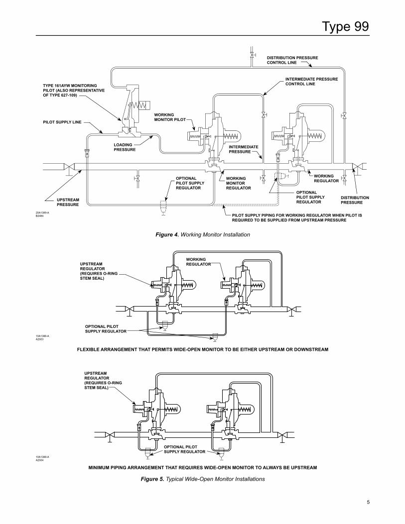
Figure 4. Working Monitor Installation
20A1389-AB2484
DISTRIBuTION PRESSuRE CONTROL LINE
TyPE 161AyW MONITORINg PILOT (ALSO REPRESENTATIvE OF TyPE 627-109)
PILOT SuPPLy LINE
WORKINg MONITOR PILOT
INTERMEDIATE PRESSuRE
INTERMEDIATE PRESSuRE CONTROL LINE
LOADINg PRESSuRE
uPSTREAM PRESSuRE
OPTIONAL PILOT SuPPLy REguLATOR
WORKINg MONITOR REguLATOR
WORKINg REguLATOR
OPTIONAL PILOT SuPPLy REguLATOR
PILOT SuPPLy PIPINg FOR WORKINg REguLATOR WHEN PILOT IS REQuIRED TO BE SuPPLIED FROM uPSTREAM PRESSuRE
DISTRIBuTION PRESSuRE
FLEXIBLE ARRANgEMENT THAT PERMITS WIDE-OPEN MONITOR TO BE EITHER uPSTREAM OR DOWNSTREAM
Figure 5. Typical Wide-Open Monitor Installations
MINIMuM PIPINg ARRANgEMENT THAT REQuIRES WIDE-OPEN MONITOR TO ALWAyS BE uPSTREAM
10A1386-AA2503
uPSTREAM REguLATOR (REQuIRES O-RINg STEM SEAL)
WORKINg REguLATOR
OPTIONAL PILOT SuPPLy REguLATOR
10A1388-AA2504
uPSTREAM REguLATOR (REQuIRES O-RINg STEM SEAL)
OPTIONAL PILOT SuPPLy REguLATOR
Type 99
6
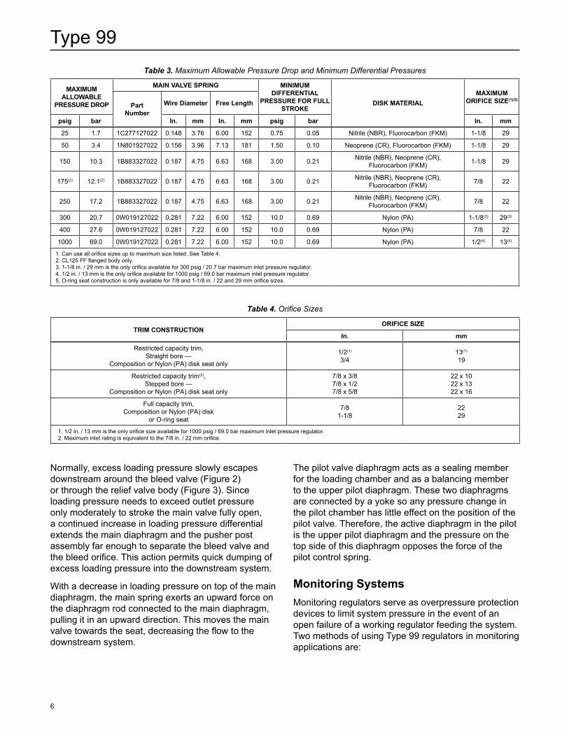
Table 3. Maximum Allowable Pressure Drop and Minimum Differential Pressures
Table 4. Orifice Sizes
MAXIMuM ALLOWABLE
PRESSuRE DROP
MAIN vALvE SPRINg MINIMuM DIFFERENTIAL
PRESSuRE FOR FuLL STROKE
DISK MATERIALMAXIMuM
ORIFICE SIZE(1)(5)Part
NumberWire Diameter Free Length
psig bar In. mm In. mm psig bar In. mm
25 1.7 1C277127022 0.148 3.76 6.00 152 0.75 0.05 Nitrile (NBR), Fluorocarbon (FKM) 1-1/8 29
50 3.4 1N801927022 0.156 3.96 7.13 181 1.50 0.10 Neoprene (CR), Fluorocarbon (FKM) 1-1/8 29
150 10.3 1B883327022 0.187 4.75 6.63 168 3.00 0.21 Nitrile (NBR), Neoprene (CR), Fluorocarbon (FKM) 1-1/8 29
175(2) 12.1(2) 1B883327022 0.187 4.75 6.63 168 3.00 0.21 Nitrile (NBR), Neoprene (CR), Fluorocarbon (FKM) 7/8 22
250 17.2 1B883327022 0.187 4.75 6.63 168 3.00 0.21 Nitrile (NBR), Neoprene (CR), Fluorocarbon (FKM) 7/8 22
300 20.7 0W019127022 0.281 7.22 6.00 152 10.0 0.69 Nylon (PA) 1-1/8(3) 29(3)
400 27.6 0W019127022 0.281 7.22 6.00 152 10.0 0.69 Nylon (PA) 7/8 22
1000 69.0 0W019127022 0.281 7.22 6.00 152 10.0 0.69 Nylon (PA) 1/2(4) 13(4)
1. Can use all orifice sizes up to maximum size listed. See Table 4.2. CL125 FF flanged body only.3. 1-1/8 in. / 29 mm is the only orifice available for 300 psig / 20.7 bar maximum inlet pressure regulator.4. 1/2 in. / 13 mm is the only orifice available for 1000 psig / 69.0 bar maximum inlet pressure regulator.5. O-ring seat construction is only available for 7/8 and 1-1/8 in. / 22 and 29 mm orifice sizes.
TRIM CONSTRuCTIONORIFICE SIZE
In. mm
Restricted capacity trim, Straight bore —
Composition or Nylon (PA) disk seat only
1/2(1)
3/413(1)
19
Restricted capacity trim(2), Stepped bore —
Composition or Nylon (PA) disk seat only
7/8 x 3/8 7/8 x 1/2 7/8 x 5/8
22 x 1022 x 1322 x 16
Full capacity trim,Composition or Nylon (PA) disk
or O-ring seat
7/8 1-1/8
2229
1. 1/2 in. / 13 mm is the only orifice size available for 1000 psig / 69.0 bar maximum inlet pressure regulator.2. Maximum inlet rating is equivalent to the 7/8 in. / 22 mm orifice.
The pilot valve diaphragm acts as a sealing member for the loading chamber and as a balancing member to the upper pilot diaphragm. These two diaphragms are connected by a yoke so any pressure change in the pilot chamber has little effect on the position of the pilot valve. Therefore, the active diaphragm in the pilot is the upper pilot diaphragm and the pressure on the top side of this diaphragm opposes the force of the pilot control spring.
Monitoring SystemsMonitoring regulators serve as overpressure protection devices to limit system pressure in the event of an open failure of a working regulator feeding the system. Two methods of using Type 99 regulators in monitoring applications are:
Normally, excess loading pressure slowly escapes downstream around the bleed valve (Figure 2) or through the relief valve body (Figure 3). Since loading pressure needs to exceed outlet pressure only moderately to stroke the main valve fully open, a continued increase in loading pressure differential extends the main diaphragm and the pusher post assembly far enough to separate the bleed valve and the bleed orifice. This action permits quick dumping of excess loading pressure into the downstream system.
With a decrease in loading pressure on top of the main diaphragm, the main spring exerts an upward force on the diaphragm rod connected to the main diaphragm, pulling it in an upward direction. This moves the main valve towards the seat, decreasing the flow to the downstream system.
Type 99
7
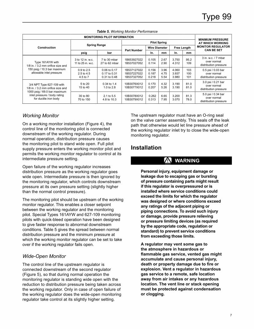
Working MonitorOn a working monitor installation (Figure 4), the control line of the monitoring pilot is connected downstream of the working regulator. During normal operation, distribution pressure causes the monitoring pilot to stand wide open. Full pilot supply pressure enters the working monitor pilot and permits the working monitor regulator to control at its intermediate pressure setting.
Open failure of the working regulator increases distribution pressure as the working regulator goes wide open. Intermediate pressure is then ignored by the monitoring regulator, which controls downstream pressure at its own pressure setting (slightly higher than the normal control pressure).
The monitoring pilot should be upstream of the working monitor regulator. This enables a closer setpoint between the working regulator and the monitoring pilot. Special Types 161AYW and 627-109 monitoring pilots with quick-bleed operation have been designed to give faster response to abnormal downstream conditions. Table 5 gives the spread between normal distribution pressure and the minimum pressure at which the working monitor regulator can be set to take over if the working regulator fails open.
Wide-Open MonitorThe control line of the upstream regulator is connected downstream of the second regulator (Figure 5), so that during normal operation the monitoring regulator is standing wide open with the reduction to distribution pressure being taken across the working regulator. Only in case of open failure of the working regulator does the wide-open monitoring regulator take control at its slightly higher setting.
The upstream regulator must have an O-ring seal on the valve carrier assembly. This seals off the leak path that otherwise would let line pressure ahead of the working regulator inlet try to close the wide-open monitoring regulator.
Installation
! WARNINg
Personal injury, equipment damage or leakage due to escaping gas or bursting of pressure containing parts might result if this regulator is overpressured or is installed where service conditions could exceed the limits for which the regulator was designed or where conditions exceed any ratings of the adjacent piping or piping connections. To avoid such injury or damage, provide pressure relieving or pressure limiting devices (as required by the appropriate code, regulation or standard) to prevent service conditions from exceeding those limits.
A regulator may vent some gas to the atmosphere in hazardous or flammable gas service, vented gas might accumulate and cause personal injury, death or property damage due to fire or explosion. vent a regulator in hazardous gas service to a remote, safe location away from air intakes or any hazardous location. The vent line or stack opening must be protected against condensation or clogging.
Table 5. Working Monitor PerformanceMONITORINg PILOT INFORMATION
MINIMuM PRESSuRE AT WHICH WORKINg
MONITOR REguLATOR CAN BE SET
ConstructionSpring Range
Pilot Spring
Part NumberWire Diameter Free Length
psig bar In. mm In. mm
Type 161AYW with 1/8 in. / 3.2 mm orifice size and 150 psig / 10.3 bar maximum
allowable inlet pressure
3 to 12 in. w.c. 11 to 25 in. w.c.
7 to 30 mbar27 to 62 mbar
1B6539270221B537027052
0.105 0.114
2.67 2.90
3.7504.312
95.2109
3 in. w.c. / 7 mbar over normal
distribution pressure
0.9 to 2.5 2.5 to 4.5 4.5 to 7
0.06 to 0.17 0.17 to 0.31 0.31 to 0.48
1B5371270221B5372270221B537327052
0.156 0.187 0.218
3.96 4.75 5.54
4.0603.9373.980
103100101
0.5 psi / 0.03 bar over normal
distribution pressure
3/4 NPT Type 627-109 with 1/8 in. / 3.2 mm orifice size and 1000 psig / 69.0 bar maximum
inlet pressure / body rating for ductile iron body
5 to 20 15 to 40
0.34 to 1.4 1.0 to 2.8
10B3076X01210B3077X012
0.170 0.207
4.32 5.26
3.1903.190
81.081.0
3.0 psi / 0.21 bar over normal
distribution pressure
35 to 80 70 to 150
2.1 to 5.5 4.8 to 10.3
10B3078X01210B3079X012
0.262 0.313
6.65 7.95
3.2003.070
81.378.0
5.0 psi / 0.34 bar over normal
distribution pressure
Type 99
8
Clean out all pipelines before installation and check to be sure the regulator has not been damaged or collected foreign material during shipping.
Apply pipe compound to the external pipe threads only with a threaded body or use suitable line gaskets and good bolting practices with a flanged body. This regulator may be installed in any position desired as long as the flow through the body is in the direction indicated by the arrow on the body. Install a three-valve bypass around the regulator if continuous operation is necessary during maintenance or inspection.
Although the standard orientation of the actuator and pilot to the main valve body is as shown in Figure 1, this orientation may be changed as far as the inlet tubing (key 24, Figure 9 or 17) will permit by loosening the union nut (key 14, Figure 9), rotating the actuator lower casing (key 29, Figure 9) as desired and tightening the union nut. To keep the pilot spring case from being plugged or the spring case from collecting moisture, corrosive chemicals or other foreign material, the vent must be pointed down, oriented to the lowest possible point on the spring case or otherwise protected. Vent orientation may be changed by rotating the spring case with respect to the pilot body.
To remotely vent a low-pressure pilot, install the vent line in place of the pressed-in vent assembly (key 60, Figure 9). Install obstruction-free tubing or piping into the 1/4 in. / 6.4 mm vent tapping. Provide protection on a remote vent by installing a screened vent cap into the remote end of the vent pipe.
To remotely vent a high-pressure pilot, remove the threaded-in vent assembly (key 72, Figure 12) from the high-pressure pilot spring case and install obstruction-free tubing or piping into the 1/4 in. / 6.4 mm vent tapping. Provide protection on a remote vent by installing a screened vent cap into the remote end of the vent pipe.
An upstream pilot supply line is not required because of the integral pilot supply tubing (key 24, Figure 9 or 17). However, as long as the 1/4 NPT tapping in the main valve body is plugged, this tubing may be disconnected from both the main valve and filter assembly (key 75, Figures 9 and 16) in order to install a pilot supply line from a desired remote location into the filter.
If the maximum pilot inlet pressure will be exceeded by main valve pressure, install a separate pressure reducing regulator (if not already provided) in the pilot supply line.
A Type 99 regulator has two 1/2 NPT control line pressure taps on opposite sides of the lower casing (key 29, Figure 9). The regulator normally comes from the factory with the tap closest to the regulator outlet left unplugged for the downstream control line as shown in Figure 1 and with opposite tap plugged.
Attach the control line from the unplugged tap 2 to 3 ft / 0.61 to 0.91 meter downstream of the regulator in a straight run of pipe. If impossible to comply with this recommendation due to the pipe arrangement, it may be better to make the control line tap nearer the regulator outlet rather than downstream of a block valve. Do not install the tap near any elbow, swage or nipple which might cause turbulence.
In many instances, it will be necessary to enlarge the downstream piping to keep flow velocities within good engineering practices. Expand the piping as close to the regulator outlet as possible.
! WARNINg
Adjustment of the pilot control spring to produce an outlet pressure higher than the upper limit of the outlet pressure range for that particular spring can cause personal injury or equipment damage due to bursting of pressure-containing parts. Dangerous accumulation of gases may also cause bursting if the maximum actuator emergency casing pressure in the Specifications section is exceeded. If the desired outlet pressure is not within the range of the pilot control spring, install a spring of the proper range according to the Maintenance section.
Each regulator is factory-set for the pressure setting specified on the order. If no setting was specified, outlet pressure was factory-set at the midrange of the pilot control spring. In all cases, check the control spring setting to make sure it is correct for the application.
Overpressure ProtectionThe Type 99 regulator has an outlet pressure rating lower than its inlet pressure rating. Complete downstream overpressure protection is required if the actual inlet pressure can exceed the regulator outlet pressure rating or the pressure ratings of any downstream equipment. Although the Type H110 relief valve provides sufficient relief capacity to protect
Type 99
9
the extra high-pressure pilot of 1000 psig / 69.0 bar maximum inlet pressure in case the Type 1301F supply regulator fails open, this protection is insufficient if the main valve body fails open. Regulator operation within ratings does not preclude the possibility of damage from external sources or from debris in the lines. A regulator should be inspected for damage periodically and after any overpressure condition.
! WARNINg
The 1000 psig / 69.0 bar maximum inlet regulator must not be used on hazardous gas service unless the Type H110 relief valve can be vented into a safe area. If vented gas can accumulate and become a hazard in enclosed conditions such as in a pit, underground or indoors, the relief valve must be repiped to carry the gas to a safe location.
A repiped vent line or stack must be located to avoid venting gas near buildings, air intakes or any hazardous location. The line or stack opening must be protected against condensation, freezing and clogging.
StartupKey numbers are referenced in Figures 9 through 15 for a low or high-pressure pilot and in Figure 18 for an extra high-pressure pilot.
1. Very slowly open the upstream block valve.2. Slowly open the hand valve (if used) in the control
line. The unit will control downstream pressure at the pilot control spring setting. If changes in the pressure setting are necessary, follow the procedure in the Adjustment section.
3. Slowly open the downstream block valve.4. Slowly close the bypass valve, if any.5. Check all connections for leaks.
AdjustmentWith proper installation completed, perform the adjustment procedure while using pressure gauges to monitor pressure.
The only adjustment on the regulator is the reduced pressure setting affected by the pilot control spring (key 43, Figure 9, 12, 14 or 18). Remove the closing cap assembly (key 46, Figure 9, 14 or 15) and turn the adjusting screw (key 45, Figure 9, 14, 15 or 18). Turning the adjusting screw clockwise into the spring case increases the controlled or reduced pressure setting. Turning the adjusting screw counterclockwise decreases the reduced pressure setting. Always replace the closing cap after making adjustments.
ShutdownInstallation arrangements may vary, but in any installation, it is important to open and close valves slowly and the outlet pressure be vented before venting inlet pressure to prevent damage caused by reverse pressurization of the regulator.
1. Isolate the regulator from the system. Close the upstream block valve to the pilot and regulator inlet.
2. Close the downstream block valve to the pilot sense connection and the regulator outlet.
3. Vent the downstream pressure by slowly opening the vent valve to vent all pressures.
4. Vent inlet pressure slowly through the vent valve to release any remaining pressure in the regulator.
MaintenanceRegulator parts are subject to normal wear and must be inspected and replaced as necessary. The frequency of inspection and replacement of parts depend on the severity of service conditions or the requirements of local, state and federal rules and regulations.
! WARNINg
Avoid personal injury or damage to property from sudden release of pressure or uncontrolled gas or other process fluid. Before starting to disassemble, isolate the pilot or regulator from all pressure and cautiously release trapped pressure from the pilot or regulator. use gauges to monitor inlet, loading and outlet pressures while releasing these pressures.
Type 99
10
On reassembly of the regulator, it is recommended that a pipe thread sealant be applied to pressure connections and fittings as indicated in Figures 7 and 9 and lubricant be applied to sliding and bearing surfaces as indicated in Figures 7 and 9, and that an anti-seize compound be applied to adjusting screw threads and other areas indicated in Figures 9 and 11.
Actuator and Standard P590 Series FilterThis procedure is to be performed if changing the main spring and spring seat for those of a different range, or if inspecting, cleaning or replacing any other parts. Unless otherwise indicated, part key numbers for a Type 99 regulator with low or high-pressure pilot and disk or O-ring seat are referenced in Figures 9 through 15, part key numbers unique to the 1000 psig / 69.0 bar maximum inlet regulator are referenced in Figure 17 and part key numbers for a Type 61HP (extra high pressure) pilot are referenced in Figure 18.1. Access to all internal actuator parts can be gained
without removing the main valve body from the line. Disconnect the loading tubing from the upper casing.
CAuTION
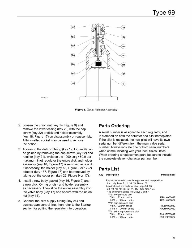
If the regulator has an indicator assembly, perform the following step carefully to avoid bending the travel indicator stem (key 103, Figure 6).
NoteThe O-rings and gaskets (keys 111 and 108, Figure 6) in the indicator assembly are static seals and need not be disturbed, unless they are leaking.
2. Remove the four cap screws (key 58, Figure 9) and lift off the spring case (key 1). Remove the travel indicator stem, if any, by unscrewing the indicator stem adaptor (key 101, Figure 6).
3. Remove the main spring seat (key 2, Figure 9) and main spring (key 3).
4. Remove the 12 cap screws (key 12, Figure 9) and hex nuts (key 13), and lift off the upper casing.
5. Remove the diaphragm (key 11, Figure 9) and diaphragm plate (key 10) by tipping it so that the lever (key 9) slips out of the pusher post (key 8).
6. Separate the diaphragm (key 11, Figure 9) and diaphragm plate (key 10) by unscrewing the diaphragm rod (key 4) from the pusher post (key 8).
Inspect the diaphragm (key 11) and pusher post gasket (key 7). Either part must be replaced if it is damaged or no longer pliable.
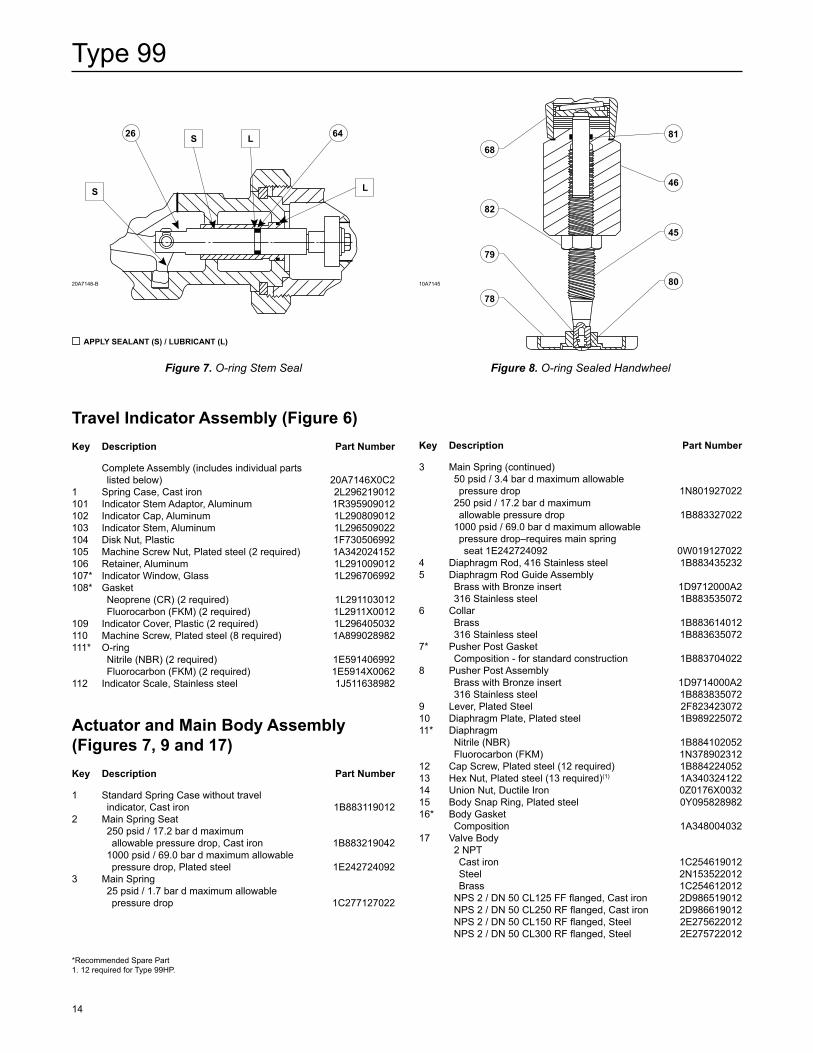
7. If the unit has a stem seal O-ring (key 64, Figure 7 or 17), this O-ring may be replaced by removing the retaining ring or cotter pin (key 28, Figure 9) and disconnecting the lever (key 9) from the valve carrier (key 26, Figure 9 or 17), removing the union nut (key 14, Figure 9), disconnecting the pilot supply tubing (key 24, Figure 9 or 17), and sliding the lower casing (key 29) away from the valve body (key 17, Figure 9), with a disk or O-ring seat, the valve carrier must be pulled out of the lower casing (key 29, Figure 9 or 17) to gain access to the O-ring. Another O-ring, held captive by the pressed-in bushing, is part of the lower casing assembly on a stem seal unit and normally does not require replacement.
8. If clogging is suspected in the upstream regulator passages, disconnect the pilot supply tubing (key 24, Figure 9 or 17), remove the filter assembly (key 75, Figure 9), and blow through it to check for filter clogging. If necessary, to clean or replace filter parts in a standard P590 Series filter assembly, remove the following as shown in Figure 16: filter body (key 1), machine screw (key 4), spring washer (key 6), gasket (key 7), washers (key 5) and filter element (key 2). Upon reassembly, one of the two washers (key 5) must go between the filter element (key 2) and filter head (key 3) and the other must go between the filter element (key 2) and gasket (key 7).
9. If the lower casing (key 29, Figure 9) was removed, install a new body gasket (key 16) and, with a disk or O-ring seat, slide the valve carrier (key 26) into the casing (key 29). Then slide the entire assembly into the valve body (disk or O-ring seat) and secure with the union nut (key 14). Secure the lever (key 9) to the valve carrier (key 26) with the retaining ring or cotter pin (key 28).
10. Loosely reassemble the diaphragm (key 11, Figure 9) and diaphragm plate (key 10) so that the bolt holes (key 11) and loading connection hole in the diaphragm can be properly aligned with the corresponding holes in the lower casing (key 29) when the lever (key 9) is fitted properly into the pusher post assembly (key 8). When this orientation is made, install the collar (key 6) and tighten the diaphragm rod (key 4) into the pusher post (key 8).
11. In order for the regulator to operate properly, the assembled collar (key 6), diaphragm (key 11),
Type 99
11
diaphragm plate (key 10), pusher post assembly (key 8) and diaphragm rod (key 4) must be mounted on the ball of the lever (key 9) so that the pusher post (key 8) orientation is as shown in Figure 9.
12. Install the upper casing (key 56, Figure 9) and secure it to the lower casing (key 29) with the twelve cap screws (key 12) torque 580 to 920 in-lbs / 65.5 to 104 N•m and hex nuts (key 13). Put lower casing (key 29) back on body and install union nut (key 14).
CAuTION
To avoid part damage due to over compressing the main spring seat (key 2), always use main spring seat 1E242724092 with main spring 0W019127022.
13. Thread the main spring seat (key 2) to the bottom of the diaphragm rod (key 4) threads and then back out 1 revolution.
14. Install a new spring case gasket (key 57, Figure 9), the spring case (key 1) and the four cap screws (key 58) with 340 to 420 in-lbs / 38.4 to 47.5 N•m of torque, making sure the indicator stem, O-ring and gaskets (keys 103, 111 and 108, Figure 6) are installed, if used.
15. Connect the loading tubing, then refer to the Startup section for putting the regulator into operation.
Type 61L, 61LD, 61LE (Low) or 61H (High Pressure) PilotThis procedure is to be performed if changing the control spring for one of a different range or if inspecting, cleaning or replacing any other pilot parts. Key numbers are referenced in Figure 9 through 15.
1. Remove the closing cap (key 46), if used, and unscrew the adjusting screw (key 45) to relieve control spring compression.
2. Disconnect the loading tubing (key 53) and pilot supply tubing (key 24).
3. Unscrew the eight cap screws (key 47) and remove the pilot assembly from the lower casing (key 29).
4. Use the projecting prong in the relay valve body (key 39) as the restraining member and remove the diaphragm nuts (key 13, Figure 9 and key 51, Figure 11). Separate the parts and inspect the diaphragms (keys 30 and 40) and O-ring seal (key 33). Replace if worn or damaged.
5. Unscrew the bleed orifice (key 52, Figure 11) from the yoke (key 37). Also to be removed with the bleed orifice are the relay disk assembly (key 48) and bleed valve (key 50). These parts can be unthreaded for inspection and replacement, if necessary.
6. When reassembling the pilot, the relay disk holder assembly (key 48, Figure 11) and both diaphragms (key 30, Figure 11 and key 40, Figure 12) should be tightened on the yoke (key 37) after it is placed in the body.
Note
Before putting the relay spring case over the diaphragm, make certain the yoke is square with respect to the prong in the relay body. (The yoke can bind on the prong if it is not square.)
7. Use care in reassembly to be sure the edges of the diaphragms (key 30, Figure 11 and key 40, Figure 12) slip properly into the recess on the lower casing (key 29, Figure 9) and relay valve body (key 39). With the pilot in place, check to see if it can be rocked. If it does not rock, it is in place and the diaphragms (key 30, Figure 11 and key 40, Figure 12) are free of wrinkles. With both diaphragms firmly in place, install the cap screws (key 47, Figure 9) using torque 150 in-lbs / 16.9 N•m of torque. Tighten using a crisscross pattern to avoid placing a strain on the unit. Set the pilot control spring (key 43) according to the adjustment information in the Startup section.
8. Reinstall the closing cap (key 46, if used). If you have a plastic closing cap, be sure that you have a vent (key 60) in place of the pipe plug installed in the low-pressure pilot spring case (key 44).
Type 61HP (Extra High Pressure) PilotThis procedure is to be performed if changing the control spring for one of a different range, or if inspecting, cleaning or replacing any other pilot parts. Key numbers are referenced in Figure 18 unless otherwise specified.
1. Unscrew the adjusting screw (key 45) to relieve control spring compression.
2. Disconnect the loading tubing (key 53, Figures 9 and 18) and pilot supply tubing (key 24, Figure 9).
3. Remove the six cap screws (key 123) which fasten the spring case (key 44), spring seat (key 68) and control spring (key 43) to the pilot body (key 39).
Type 99
12
4. Unscrew the diaphragm nut (key 128) and remove a diaphragm plate (key 41A), diaphragm (key 40) and another diaphragm plate (key 41B).
5. Unscrew the eight cap screws (key 47) and remove the pilot body (key 39) and gasket (key 126). Remove six cap screws (key 35), seal washers and the flange adaptor (key 125).
6. Unscrew the relief valve body (key 119) and remove a diaphragm plate (key 41C), diaphragm (key 30) and another diaphragm plate (key 41D). Inspect the diaphragm inserts (key 150) and both diaphragms (keys 30 and 40). Replace if worn or damaged.
7. The relief valve assembly can be further disassembled for inspection by unscrewing the relief valve cap (key 118).
8. Four machine screws (key 130) hold both yoke caps (keys 37 and 116) to the yoke legs (key 31). Separate these parts to expose the pilot valve.
9. Unscrew the inlet orifice (key 38) to inspect its seat, the inlet valve plug (key 117) and valve spring (key 124).
NoteMake certain that the yoke assembly is square with respect to the cross member of the body casting so that it will not bind on the body.
10. When reassembling, screw in the inlet orifice (key 38) all the way and secure the yoke caps (keys 37 and 116) to the yoke legs (key 31). Replace two diaphragm plates (keys 41B and 41D), the diaphragms (keys 30 and 40) and inserts, two more diaphragm plates (keys 41A and 41C), the diaphragm nut (key 128) and the relief valve assembly.
11. Assemble the control spring (key 43) and spring seat (key 68) into the body and spring case (key 44), being careful that the diaphragms (keys 30 and 40) are free of wrinkles and properly in place, and evenly installing the cap screws (key 123) in a crisscross pattern to avoid placing a strain on the unit. Install the body flange adaptor (key 125) with seal washers (key 126) and cap screws (key 47). Install a new gasket and secure the pilot to the lower casing (key 29) with eight cap screws (key 47). Set the control spring (key 43) according to the adjustment information in the Startup section.
Converting the PilotNote
A complete pilot assembly rather than individual parts may be ordered for the following conversion procedure. When a low-pressure pilot is ordered for field conversion of a high-pressure pilot or vice versa, the replacement pilot assembly comes complete with a pilot cover (key 132, Figure 9). Remove this cover before installing the replacement pilot on the existing regulator. The cover can then be installed on the removed pilot to form a complete Type 61 (low or high pressure) pilot for use elsewhere.
When changing one pilot construction (low pressure, high pressure or extra high pressure) for another, all parts attached to the lower casing (key 29, Figure 9) may need to be replaced with those appropriate for the desired construction. At the very least, when changing from a low to high-pressure pilot or vice versa, everything below the lower pilot diaphragm (key 40, Figure 9) except the cap screws and the hex nut (keys 47 and 13, Figure 9) will need to be replaced. Actuator and main valve parts may remain unchanged unless a change in service conditions requires a change in seat construction, main spring or main spring seat. See the Parts List sections for obtaining the appropriate conversion parts.
Main valve Trim with Disk or O-ring SeatThis procedure is to be performed if inspecting, cleaning or replacing trim parts. Part key numbers for a Type 99 regulator with disk or O-ring seat are referenced in Figures 9 and 10 and part key numbers for the disk seat unique to the 1000 psig / 69.0 bar maximum inlet regulator are referenced in Figure 17.
Note
All trim maintenance may be performed with the valve body (key 17, Figure 9 or 17) in the line and with the elbow (key 23), pilot supply tubing (key 24) and pilot supply regulator (if used) attached to the valve body unless the valve body itself will be replaced.
1. Disconnect the pilot supply tubing (key 24) and downstream control line.
Type 99
13
2. Loosen the union nut (key 14, Figure 9) and remove the lower casing (key 29) with the cap screw (key 22) or disk and holder assembly (key 18, Figure 17) on disassembly or reassembly. A thin-walled socket may be used to remove the orifi ce.
3. Access to the disk or O-ring (key 19, Figure 9) can be gained by removing the cap screw (key 22) and retainer (key 21), while on the 1000 psig / 69.0 bar maximum inlet regulator the entire disk and holder assembly (key 18, Figure 17) is removed as a unit. If necessary, the holder (key 18, Figure 9 or 17) or adaptor (key 157, Figure 17) can be removed by taking out the cotter pin (key 25, Figure 9 or 17).
4. Install a new body gasket (key 16, Figure 9) and a new disk, O-ring or disk and holder assembly as necessary. Then slide the entire assembly into the valve body (key 17) and secure with the union nut (key 14).
5. Connect the pilot supply tubing (key 24) and downstream control line, then refer to the Startup section for putting the regulator into operation.
Parts OrderingA serial number is assigned to each regulator, and it is stamped on both the actuator and pilot nameplates. If the pilot is replaced, the new pilot will have its own serial number different from the main valve serial number. Always indicate one or both serial numbers when communicating with your local Sales Offi ce. When ordering a replacement part, be sure to include the complete eleven-character part number.
Parts ListKey Description Part Number
Repair kits include parts for regulator with composition trim only, keys 7, 11, 16, 19, 20 and 57.
Also included are parts for pilot, keys 30, 33, 38, 40, 48, 49, 50, 52, 71, 117, 126, 129, 150,
153 and P590 Series fi lter, keys 2 and 7. With low-pressure pilot 7/8 in. / 22 mm orifi ce R99LX000012 1-1/8 in. / 29 mm orifi ce R99LX000022 With high-pressure pilot 7/8 in. / 22 mm orifi ce R99HX000012 1-1/8 in. / 29 mm orifi ce R99HX000022 With extra high-pressure pilot 7/8 in. / 22 mm orifi ce R99HPX00012 1-1/8 in. / 29 mm orifi ce R99HPX00022
Figure 6. Travel Indicator Assembly
20A7146-B
OP
EN
102
105
107
104
106
105
101
108
109
112
110
111
103
1
Type 99
14
Travel Indicator Assembly (Figure 6)Key Description Part Number
Complete Assembly (includes individual parts listed below) 20A7146X0C2
1 Spring Case, Cast iron 2L296219012101 Indicator Stem Adaptor, Aluminum 1R395909012102 Indicator Cap, Aluminum 1L290809012103 Indicator Stem, Aluminum 1L296509022104 Disk Nut, Plastic 1F730506992105 Machine Screw Nut, Plated steel (2 required) 1A342024152106 Retainer, Aluminum 1L291009012107* Indicator Window, Glass 1L296706992108* Gasket Neoprene (CR) (2 required) 1L291103012 Fluorocarbon (FKM) (2 required) 1L2911X0012109 Indicator Cover, Plastic (2 required) 1L296405032110 Machine Screw, Plated steel (8 required) 1A899028982111* O-ring Nitrile (NBR) (2 required) 1E591406992 Fluorocarbon (FKM) (2 required) 1E5914X0062112 Indicator Scale, Stainless steel 1J511638982
Actuator and Main Body Assembly (Figures 7, 9 and 17)Key Description Part Number
1 Standard Spring Case without travel indicator, Cast iron 1B8831190122 Main Spring Seat 250 psid / 17.2 bar d maximum allowable pressure drop, Cast iron 1B883219042 1000 psid / 69.0 bar d maximum allowable pressure drop, Plated steel 1E2427240923 Main Spring 25 psid / 1.7 bar d maximum allowable pressure drop 1C277127022
Key Description Part Number
3 Main Spring (continued) 50 psid / 3.4 bar d maximum allowable pressure drop 1N801927022 250 psid / 17.2 bar d maximum allowable pressure drop 1B883327022 1000 psid / 69.0 bar d maximum allowable pressure drop–requires main spring seat 1E242724092 0W0191270224 Diaphragm Rod, 416 Stainless steel 1B8834352325 Diaphragm Rod Guide Assembly Brass with Bronze insert 1D9712000A2 316 Stainless steel 1B8835350726 Collar Brass 1B883614012 316 Stainless steel 1B8836350727* Pusher Post Gasket Composition - for standard construction 1B8837040228 Pusher Post Assembly Brass with Bronze insert 1D9714000A2 316 Stainless steel 1B8838350729 Lever, Plated Steel 2F82342307210 Diaphragm Plate, Plated steel 1B98922507211* Diaphragm Nitrile (NBR) 1B884102052 Fluorocarbon (FKM) 1N37890231212 Cap Screw, Plated steel (12 required) 1B88422405213 Hex Nut, Plated steel (13 required)(1) 1A34032412214 Union Nut, Ductile Iron 0Z0176X003215 Body Snap Ring, Plated steel 0Y09582898216* Body Gasket Composition 1A34800403217 Valve Body 2 NPT Cast iron 1C254619012 Steel 2N153522012 Brass 1C254612012 NPS 2 / DN 50 CL125 FF flanged, Cast iron 2D986519012 NPS 2 / DN 50 CL250 RF flanged, Cast iron 2D986619012 NPS 2 / DN 50 CL150 RF flanged, Steel 2E275622012 NPS 2 / DN 50 CL300 RF flanged, Steel 2E275722012
Figure 7. O-ring Stem Seal Figure 8. O-ring Sealed Handwheel
20A7148-B 10A7145
*Recommended Spare Part1. 12 required for Type 99HP.
APPLy SEALANT (S) / LuBRICANT (L)
S
S L
L
6426
6881
46
45
80
82
79
78
Type 99
15
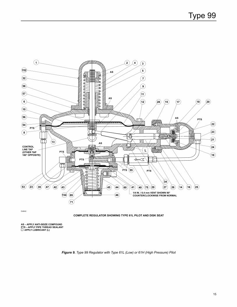
Figure 9. Type 99 Regulator with Type 61L (Low) or 61H (High Pressure) Pilot
COMPLETE REguLATOR SHOWINg TyPE 61L PILOT AND DISK SEAT
AS – APPLy ANTI-SEIZE COMPOuNDPTS – APPLy PIPE THREAD SEALANT
APPLy LuBRICANT (L)
DJ6642
CONTROL LINE TAP (OTHER TAP 180° OPPOSITE)
1/4 IN. / 6.4 mm VENT SHOWN 90° COUNTERCLOCKWISE FROM NORMAL
PTS
AS
AS
L
1
6
32
58
57
10
152
8
56
54
53 23 39 47 42 43
69
71
154
45 44 41 40
46
60 75 29
34
27 26 14 16 25
55
12
11
9
7
5
3 4 2
19
24
21
23
22
2018171528
13
PTS
PTS
PTS PTS
PTS
AS
AS
Type 99
16
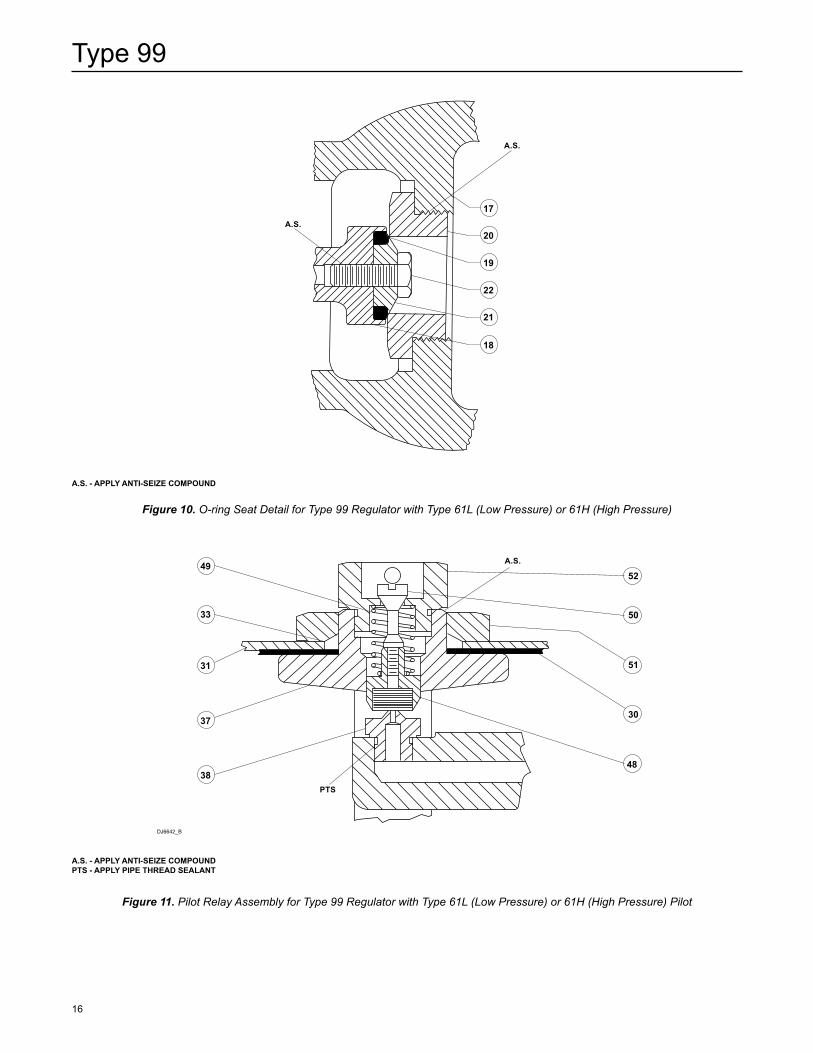
Figure 11. Pilot Relay Assembly for Type 99 Regulator with Type 61L (Low Pressure) or 61H (High Pressure) Pilot
Figure 10. O-ring Seat Detail for Type 99 Regulator with Type 61L (Low Pressure) or 61H (High Pressure)
A.S. - APPLy ANTI-SEIZE COMPOuND
A.S. - APPLy ANTI-SEIZE COMPOuNDPTS - APPLy PIPE THREAD SEALANT
DJ6642_B
17
19
18
20
22
21
A.S.
A.S.
49
33
31
37
38
52
50
51
30
48
A.S.
PTS
Type 99
17
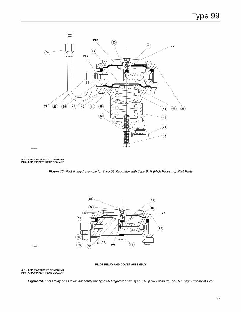
Figure 13. Pilot Relay and Cover Assembly for Type 99 Regulator with Type 61L (Low Pressure) or 61H (High Pressure) Pilot
Figure 12. Pilot Relay Assembly for Type 99 Regulator with Type 61H (High Pressure) Pilot Parts
PILOT RELAy AND COvER ASSEMBLy
C0289-1C
30A6800
A.S. - APPLy ANTI-SEIZE COMPOuNDPTS - APPLy PIPE THREAD SEALANT
A.S. - APPLy ANTI-SEIZE COMPOuNDPTS - APPLy PIPE THREAD SEALANT
42 2943
44
72
45
53
5133
13
23 39 47 40 41 68
82
54
A.S.
PTS
PTS
483733
30
51
49
50
52 31
38
29
13PTS
A.S.
Type 99
18
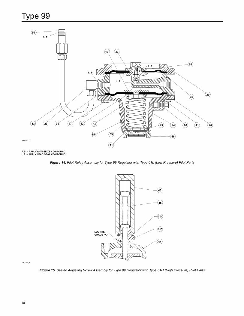
Figure 15. Sealed Adjusting Screw Assembly for Type 99 Regulator with Type 61H (High Pressure) Pilot Parts
Figure 14. Pilot Relay Assembly for Type 99 Regulator with Type 61L (Low Pressure) Pilot Parts
10A7151_A
30A6923_D
A.S. – APPLy ANTI-SEIZE COMPOuNDL.S. – APPLy LEAD SEAL COMPOuND
54
53 23 39 47 42 43
154 69
71
29
4041604445
46
13 33
51
30
L. S.
L. S.
L. S.
A. S.
46
45
114
115
44
LOCTITEGRADE “A”
Type 99
19
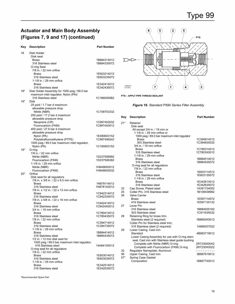
Actuator and Main Body Assembly (Figures 7, 9 and 17) (continued)
Key Description Part Number
18 Disk Holder Disk seat Brass 1B884314012 316 Stainless steel 1B884335072 O-ring Seat 7/8 in. / 22 mm orifi ce Brass 1E603214012 316 Stainless steel 1E603235072 1-1/8 in. / 29 mm orifi ce Brass 1E342414012 316 Stainless steel 1E34243507218* Disk Holder Assembly for 1000 psig / 69.0 bar maximum inlet regulator, Nylon (PA)/ 316 Stainless steel 1C1860000B219* Disk 25 psid / 1.7 bar d maximum allowable pressure drop Nitrile (NBR) 1C158703332 250 psid / 17.2 bar d maximum allowable pressure drop Neoprene (CR) 1C997403032 Fluorocarbon (FKM) 1C9974X0012 400 psid / 27.6 bar d maximum allowable pressure drop Nylon (PA) 1E480603152 Polytetrafl uoroethylene (PTFE) 1C997406242 1000 psig / 69.0 bar maximum inlet regulator, Nylon (PA) 1C185903152 19* O-ring 7/8 in. / 22 mm orifi ce Nitrile (NBR) 1D237506992 Fluorocarbon (FKM) 1D237506382 1-1/8 in. / 29 mm orifi ce Nitrile (NBR) 1H8498X0012 Fluorocarbon (FKM) 1H8498X003220* Orifi ce Disk seat for all regulators 7/8 in. x 3/8 in. / 22 x 9.5 mm orifi ce Brass 1N878114012 316 Stainless steel 1N8781X0012 7/8 in. x 1/2 in. / 22 x 13 mm orifi ce Brass 1C942314012 316 Stainless steel 1C942335072 7/8 in. x 5/8 in. / 22 x 16 mm orifi ce Brass 1C942414012 316 Stainless steel 1C9424X0012 3/4 in. / 19 mm orifi ce Brass 1C780414012 316 Stainless steel 1C780435072 7/8 in. / 22 mm orifi ce Brass 1C394714012 316 Stainless steel 1C394735072 1-1/8 in. / 29 mm orifi ce Brass 1B884414012 316 Stainless steel 1B884435072 1/2 in. / 13 mm disk seat for 1000 psig / 69.0 bar maximum inlet regulator, 416 Stainless steel 14A8410X012 O-ring seat for all regulators 7/8 in. / 22 mm orifi ce Brass 1E603014012 316 Stainless steel 1E603035072 1-1/8 in. / 29 mm orifi ce Brass 1E342514012 316 Stainless steel 1E342535072
Key Description Part Number
21* Retainer Disk seat All except 3/4 in. / 19 mm or 1-1/8 in. / 29 mm orifi ce or 1000 psig / 69.0 bar maximum inlet regulator Brass 1C394814012 303 Stainless steel 1C394835032 3/4 in. / 19 mm orifi ce Brass 1C780314012 316 Stainless steel 1C7803X0012 1-1/8 in. / 29 mm orifi ce Brass 1B884514012 316 Stainless steel 1B884535072 O-ring seat for all regulators 7/8 in. / 22 mm orifi ce Brass 1E603114012 316 Stainless steel 1E603135072 1-1/8 in. / 29 mm orifi ce Brass 1E342614012 316 Stainless steel 1E34263507222 Cap Screw, Plated steel 1A39172405225 Cotter Pin, 316 Stainless steel 1B10843899226 Valve Carrier Brass 1E597114072 416 Stainless steel 1E59713513227 Lever Pin 316 Stainless steel 1B884935162 303 Stainless steel 1C91163503228 Retaining Ring for brass trim, Stainless steel (2 required) 1B8850X0012 Cotter Pin for Stainless steel trim, 316 Stainless steel (2 required) 1A86653702229 Lower Casing, Cast iron Standard 4B983719012 Lower Casing Assembly for use with O-ring stem seal, Cast iron with Stainless steel guide bushing Complete with Nitrile (NBR) O-ring 2R7230000A2 Complete with Fluorocarbon (FKM) O-ring 2R7230X002232 Regulator Nameplate, Aluminum - - - - - - - - - - -56 Upper Casing, Cast iron 3B88761901257* Spring Case Gasket Composition 1B8877X0012
*Recommended Spare Part
Figure 16. Standard P590 Series Filter Assembly
AJ5004-AA2135/IL
PTS – APPLy PIPE THREAD SEALANT
7 1 4 3
PTS
6 5 2 5
Type 99
20
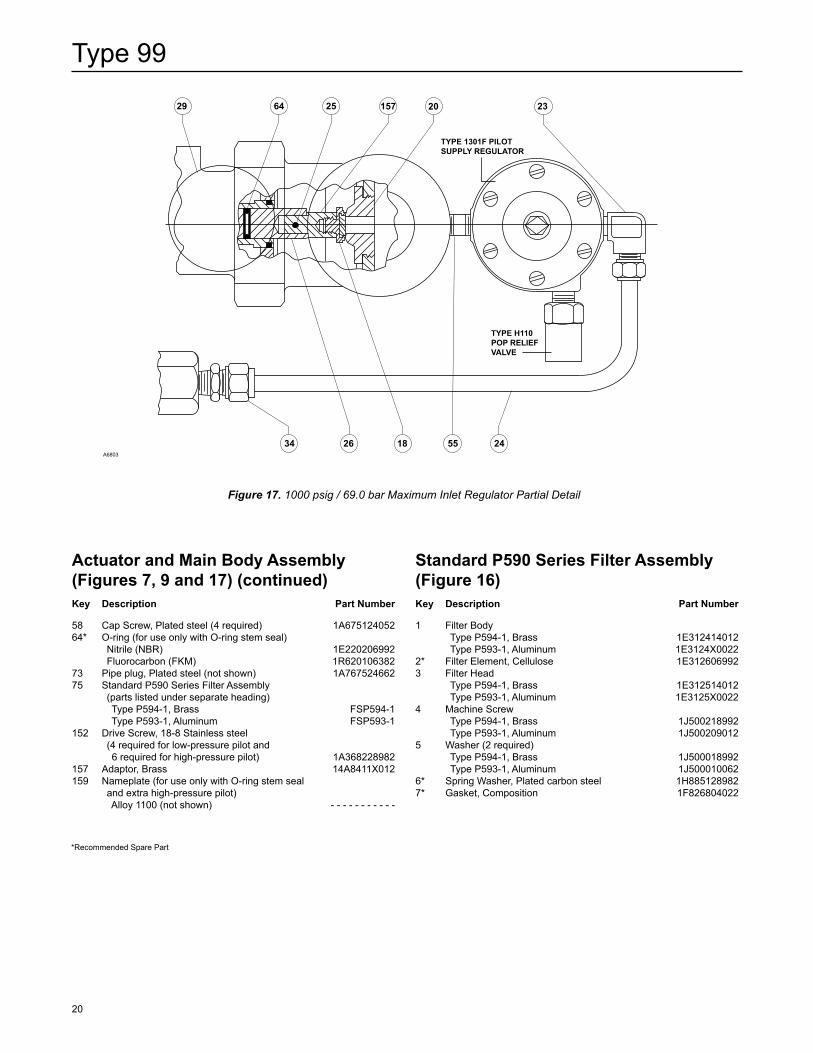
Actuator and Main Body Assembly (Figures 7, 9 and 17) (continued) Key Description Part Number
58 Cap Screw, Plated steel (4 required) 1A67512405264* O-ring (for use only with O-ring stem seal) Nitrile (NBR) 1E220206992 Fluorocarbon (FKM) 1R62010638273 Pipe plug, Plated steel (not shown) 1A76752466275 Standard P590 Series Filter Assembly (parts listed under separate heading) Type P594-1, Brass FSP594-1 Type P593-1, Aluminum FSP593-1152 Drive Screw, 18-8 Stainless steel (4 required for low-pressure pilot and 6 required for high-pressure pilot) 1A368228982157 Adaptor, Brass 14A8411X012159 Nameplate (for use only with O-ring stem seal and extra high-pressure pilot) Alloy 1100 (not shown) - - - - - - - - - - -
Standard P590 Series Filter Assembly (Figure 16)Key Description Part Number
1 Filter Body Type P594-1, Brass 1E312414012 Type P593-1, Aluminum 1E3124X00222* Filter Element, Cellulose 1E3126069923 Filter Head Type P594-1, Brass 1E312514012 Type P593-1, Aluminum 1E3125X00224 Machine Screw Type P594-1, Brass 1J500218992 Type P593-1, Aluminum 1J5002090125 Washer (2 required) Type P594-1, Brass 1J500018992 Type P593-1, Aluminum 1J5000100626* Spring Washer, Plated carbon steel 1H8851289827* Gasket, Composition 1F826804022
Figure 17. 1000 psig / 69.0 bar Maximum Inlet Regulator Partial Detail
A6803
*Recommended Spare Part
64 25 157 20 2329
2455182634
TYPE 1301F PILOTSUPPLY REGULATOR
TYPE H110POP RELIEFVALVE
Type 99
21
Pilot and Tubing Parts(2) Low or High-Pressure Pilot (Figures 8, 10, 11, 12, 13, 14 and 15)Key Description Part Number
23 Elbow (2 required) - - - - - - - - - - -24 Pilot Supply Tubing, disk or O-ring main valve seat - - - - - - - - - - -30* Upper Relay Diaphragm Nitrile (NBR) 1B885202052 Fluorocarbon (FKM) 1N16280233231 Upper Relay Diaphragm Plate, Plated steel For use with all low-pressure pilots except Type 61LE 1B989325072 For use with all high-pressure pilots and Type 61LE low-pressure pilot 1D55842507233* O-ring Seal Nitrile (NBR) 1B885506992 Fluorocarbon (FKM) 1B8855X001234 Connector - - - - - - - - - - -37 Yoke Zinc 1D66254401238 Relay Orifice, Stainless steel For use with 25 psi / 1.7 bar maximum allowable pressure drop actuator main spring 1D373735032 For use with all other main springs 1C52013503239 Relay Valve Body, Cast iron 2J58191901240* Lower Relay Diaphragm Low-pressure pilot Nitrile (NBR) 1B886002052 Fluorocarbon (FKM) 1N536102332 High-pressure pilot Neoprene (CR) 1B894202192 Fluorocarbon (FKM) (2 required) 1N16270230241 Lower Relay Diaphragm Plate, Plated steel Low-pressure pilot 1B989425072 High-pressure pilot 1D55832507242 Spring Seat, Plated steel Low-pressure pilot 1B886225072 High-pressure pilot 1D55852507243 Control Spring, Plated steel For use only with Type 61LD low-pressure pilot 2 to 4 in. w.c. / 5 to 10 mbar, Orange 1B558527052 3 to 12 in. w.c. / 7 to 30 mbar, Unpainted 1C680627222 For use with all low-pressure pilots 0.25 to 2 psig / 0.02 to 0.14 bar, Red 1B886327022 1 to 5 psig / 0.07 to 0.35 bar, Yellow 1J857827022 2 to 10 psig / 0.14 to 0.69 bar, Blue 1B886427022 5 to 15 psig / 0.35 to 1.0 bar, Brown 1J857927142 10 to 20 psig / 0.69 to 1.4 bar, Green 1B886527022 For use with high-pressure pilot 10 to 65 psig / 0.69 to 4.5 bar, Green stripe 0Y06642702244 Spring Case, Cast iron Low-pressure pilot 1B983919012 High-pressure pilot Standard 1B984119012 For use with closing cap (not shown) 1H23261901245 Adjusting Screw Low-pressure pilot Standard, Zinc 1B537944012 Handwheel-style, Plated steel 1J496428982 O-ring sealed handwheel assembly, Brass 1R759414012 Brass Cap with external sealed adjusting screw, Plated steel 1D995448702 High-pressure pilot Standard, Plated steel 1A279128982 For use with closing cap, 1H236514012 Plated steel 1J881524102 Type 662 18B3500X022
Key Description Part Number
46 Closing Cap Low-pressure pilot For use with standard low-pressure pilot, Plastic T11069X0012 For use with standard low-pressure pilot, Steel 1E422724092 For use with handwheel-style low-pressure pilot, Brass (not shown) 1A926114012 For use with O-ring sealed handwheel, Brass 1R759314012 High-pressure pilot For use with high-pressure pilot with spring case 1H232619012, Brass (not shown) 1H23651401247 Cap Screw, Plated steel (8 required) 1B98962405248* Relay Disk Assembly Brass/Nitrile (NBR) 1B8868000A2 303 Stainless steel/Nitrile (NBR) 1B8868000B2 Brass/Fluorocarbon (FKM) 1B8868X0012 303 Stainless steel/Fluorocarbon (FKM) 1B8868X002249 Bleed Valve Spring, Stainless steel For use with low-pressure pilot with relay orifice 1D373735032 or bleed valve 1H951635132 1E643637022 For use with all low and high-pressure pilots Inlet pressure up to 250 psig / 17.2 bar 1C911537022 Inlet pressure over 250 psig / 17.2 bar 1N85913702250 Bleed Valve, Stainless steel For use with Type 61LD low-pressure pilot with bleed valve spring 1E643637022 1H951635132 For use with all low and high-pressure pilots 1D98673513251 Diaphragm Nut Brass 1B989514012 316 Stainless steel 1B98953507252* Bleed Orifice, 316 Stainless steel 1B88733503253 Loading Tubing - - - - - - - - - - -54 Connector - - - - - - - - - - -55 Pipe Nipple (1 required for 90º orientation and 2 required with SST tubing) - - - - - - - - - - -59 Pipe plug, Steel (not shown) - - - - - - - - - - -60 Type Y602-12 Vent Assembly (low-pressure pilot only) 27A5516X01268 Spring Seat Handwheel-style low-pressure pilot, Zinc-plated steel, (not shown) 1J618124092 High-pressure pilot, Zinc-plated steel 16A9812X01269 Pilot Nameplate - - - - - - - - - - - 71* Closing Cap Gasket (for use only with low-pressure pilot), Neoprene (CR) 1P75330699272 Type Y602-1 Vent Assembly (for use only with standard high-pressure pilot spring case) 17A6570X01278 Handwheel (for use only with handwheel-style low-pressure pilot), Zinc 1J49614401279 Machine Screw (for use only with handwheel-style low-pressure pilot), Plated steel 16A5763X01280 Lockwasher For use only with handwheel-style low-pressure pilot, Steel 1A352332992 For use with Brass cap with external sealed adjusting screw 1V20569901281* O-ring (for use only with O-ring sealed handwheel assembly) low-pressure pilot, Nitrile (NBR) 1D54150699282 Hex nut For use only with O-ring sealed handwheel assembly low-pressure pilot 1A351124122 For use with Brass cap with external sealed adjusting screw, Zinc 1A353724122 For use with high-pressure pilot, Plated steel 1A352424122
*Recommended Spare Part2. An entire pilot assembly may be ordered from your local Sales Office by specifying a Type 61L, 61H or 61HP pilot for field conversion.
Type 99
22
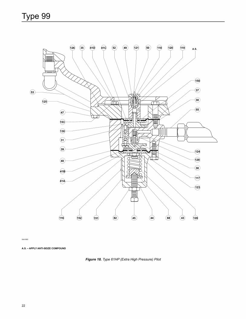
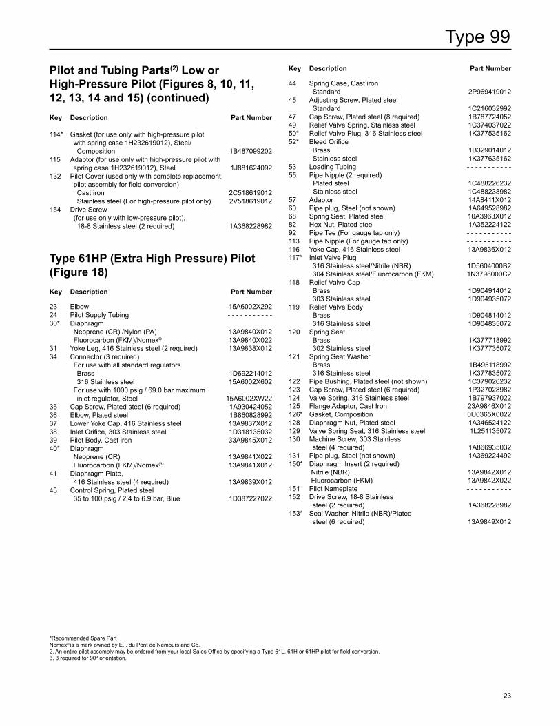
Figure 18. Type 61HP (Extra High Pressure) Pilot
A.S. – APPLy ANTI-SEIZE COMPOuND
54A1905
50495241C 118121 120 119 A.S.41D35126
150
37
30
55
124
129
117
123
1284368
38
151152116 444582
47
53
41A
40
39
31
130
125
153
41B
Type 99
23
Key Description Part Number
44 Spring Case, Cast iron Standard 2P96941901245 Adjusting Screw, Plated steel Standard 1C21603299247 Cap Screw, Plated steel (8 required) 1B78772405249 Relief Valve Spring, Stainless steel 1C37403702250* Relief Valve Plug, 316 Stainless steel 1K37753516252* Bleed Orifice Brass 1B329014012 Stainless steel 1K37763516253 Loading Tubing - - - - - - - - - - -55 Pipe Nipple (2 required) Plated steel 1C488226232 Stainless steel 1C48823898257 Adaptor 14A8411X01260 Pipe plug, Steel (not shown) 1A64952898268 Spring Seat, Plated steel 10A3963X01282 Hex Nut, Plated steel 1A35222412292 Pipe Tee (For gauge tap only) - - - - - - - - - - - 113 Pipe Nipple (For gauge tap only) - - - - - - - - - - -116 Yoke Cap, 416 Stainless steel 13A9836X012117* Inlet Valve Plug 316 Stainless steel/Nitrile (NBR) 1D5604000B2 304 Stainless steel/Fluorocarbon (FKM) 1N3798000C2118 Relief Valve Cap Brass 1D904914012 303 Stainless steel 1D904935072119 Relief Valve Body Brass 1D904814012 316 Stainless steel 1D904835072120 Spring Seat Brass 1K377718992 302 Stainless steel 1K377735072121 Spring Seat Washer Brass 1B495118992 316 Stainless steel 1K377835072122 Pipe Bushing, Plated steel (not shown) 1C379026232123 Cap Screw, Plated steel (6 required) 1P327028982124 Valve Spring, 316 Stainless steel 1B797937022125 Flange Adaptor, Cast Iron 23A9846X012126* Gasket, Composition 0U0365X0022128 Diaphragm Nut, Plated steel 1A346524122129 Valve Spring Seat, 316 Stainless steel 1L251135072130 Machine Screw, 303 Stainless steel (4 required) 1A866935032131 Pipe plug, Steel (not shown) 1A369224492150* Diaphragm Insert (2 required) Nitrile (NBR) 13A9842X012 Fluorocarbon (FKM) 13A9842X022151 Pilot Nameplate - - - - - - - - - - -152 Drive Screw, 18-8 Stainless steel (2 required) 1A368228982153* Seal Washer, Nitrile (NBR)/Plated steel (6 required) 13A9849X012
Pilot and Tubing Parts(2) Low or High-Pressure Pilot (Figures 8, 10, 11, 12, 13, 14 and 15) (continued)Key Description Part Number
114* Gasket (for use only with high-pressure pilot with spring case 1H232619012), Steel/ Composition 1B487099202115 Adaptor (for use only with high-pressure pilot with spring case 1H232619012), Steel 1J881624092132 Pilot Cover (used only with complete replacement pilot assembly for field conversion) Cast iron 2C518619012 Stainless steel (For high-pressure pilot only) 2V518619012154 Drive Screw (for use only with low-pressure pilot), 18-8 Stainless steel (2 required) 1A368228982
Type 61HP (Extra High Pressure) Pilot (Figure 18)Key Description Part Number
23 Elbow 15A6002X29224 Pilot Supply Tubing - - - - - - - - - - -30* Diaphragm Neoprene (CR) /Nylon (PA) 13A9840X012 Fluorocarbon (FKM)/Nomex® 13A9840X02231 Yoke Leg, 416 Stainless steel (2 required) 13A9838X01234 Connector (3 required) For use with all standard regulators Brass 1D692214012 316 Stainless steel 15A6002X602 For use with 1000 psig / 69.0 bar maximum inlet regulator, Steel 15A6002XW2235 Cap Screw, Plated steel (6 required) 1A93042405236 Elbow, Plated steel 1B86082899237 Lower Yoke Cap, 416 Stainless steel 13A9837X01238 Inlet Orifice, 303 Stainless steel 1D31813503239 Pilot Body, Cast iron 33A9845X01240* Diaphragm Neoprene (CR) 13A9841X022 Fluorocarbon (FKM)/Nomex(3) 13A9841X01241 Diaphragm Plate, 416 Stainless steel (4 required) 13A9839X01243 Control Spring, Plated steel 35 to 100 psig / 2.4 to 6.9 bar, Blue 1D387227022
*Recommended Spare Part Nomex® is a mark owned by E.I. du Pont de Nemours and Co.2. An entire pilot assembly may be ordered from your local Sales Office by specifying a Type 61L, 61H or 61HP pilot for field conversion.3. 3 required for 90º orientation.
Type 99
©Emerson Process Management Regulator Technologies, Inc., 1979, 2016; All Rights Reserved
The Emerson logo is a trademark and service mark of Emerson Electric Co. All other marks are the property of their prospective owners. Fisher is a mark owned by Fisher Controls International LLC, a business of Emerson Process Management.
The contents of this publication are presented for informational purposes only, and while every effort has been made to ensure their accuracy, they are not to be construed as warranties or guarantees, express or implied, regarding the products or services described herein or their use or applicability. We reserve the right to modify or improve the designs or specifications of such products at any time without notice.
Emerson Process Management Regulator Technologies, Inc. does not assume responsibility for the selection, use or maintenance of any product. Responsibility for proper selection, use and maintenance of any Emerson Process Management Regulator Technologies, Inc. product remains solely with the purchaser.
Industrial Regulators
Emerson Process Management Regulator Technologies, Inc.
USA - HeadquartersMcKinney, Texas 75070 USATel: +1 800 558 5853Outside U.S. +1 972 548 3574
Asia-PacificShanghai 201206, ChinaTel: +86 21 2892 9000
EuropeBologna 40013, ItalyTel: +39 051 419 0611
Middle East and AfricaDubai, United Arab EmiratesTel: +971 4811 8100
Natural Gas Technologies
Emerson Process ManagementRegulator Technologies, Inc.
USA - HeadquartersMcKinney, Texas 75070 USATel: +1 800 558 5853Outside U.S. +1 972 548 3574
Asia-PacificSingapore 128461, SingaporeTel: +65 6770 8337
EuropeBologna 40013, ItalyTel: +39 051 419 0611Chartres 28008, FranceTel: +33 2 37 33 47 00
Middle East and AfricaDubai, United Arab EmiratesTel: +971 4811 8100
TESCOM
Emerson Process ManagementTescom Corporation
USA - HeadquartersElk River, Minnesota 55330-2445, USATels: +1 763 241 3238 +1 800 447 1250
EuropeSelmsdorf 23923, GermanyTel: +49 38823 31 287
Asia-PacificShanghai 201206, ChinaTel: +86 21 2892 9499
For further information visit www.fisherregulators.com