Embed Size (px)
Citation preview
User M
anual
ControlNet Network In
terf
ace D
evic
e
ADV ANC EDMIC RO CON T RO L S INC.
NEXUSSSI Interface Unit
NX2E4C
Manual #: 940-0N020

GENERAL INFORMATION
Important User InformationThe products and application data described in this manual are useful in a wide variety of different applica-tions. Therefore, the user and others responsible for applying these products described herein are responsible for determining the acceptability for each application. While efforts have been made to provide accurate information within this manual, AMCI assumes no responsibility for the application or the completeness of the information contained herein.
UNDER NO CIRCUMSTANCES WILL ADVANCED MICRO CONTROLS, INC. BE RESPONSIBLE OR LIABLE FOR ANY DAMAGES OR LOSSES, INCLUDING INDIRECT OR CONSEQUENTIAL DAM-AGES OR LOSSES, ARISING FROM THE USE OF ANY INFORMATION CONTAINED WITHIN THIS MANUAL, OR THE USE OF ANY PRODUCTS OR SERVICES REFERENCED HEREIN.
Throughout this manual the following two notices are used to highlight important points.
WARNINGS tell you when people may be hurt or equipment may be damaged if the procedure is not followed properly.
CAUTIONS tell you when equipment may be damaged if the procedure is not followed properly.
No patent liability is assumed by AMCI, with respect to use of information, circuits, equipment, or software described in this manual.
The information contained within this manual is subject to change without notice.
Standard WarrantyADVANCED MICRO CONTROLS, INC. warrants that all equipment manufactured by it will be free from defects, under normal use, in materials and workmanship for a period of [1] year. Within this warranty period, AMCI shall, at its option, repair or replace, free of charge, any equipment covered by this warranty which is returned, shipping charges prepaid, within one year from date of invoice, and which upon examina-tion proves to be defective in material or workmanship and not caused by accident, misuse, neglect, alteration, improper installation or improper testing.
The provisions of the "STANDARD WARRANTY" are the sole obligations of AMCI and excludes all other warranties expressed or implied. In no event shall AMCI be liable for incidental or consequential damages or for delay in performance of this warranty.
Returns PolicyAll equipment being returned to AMCI for repair or replacement, regardless of warranty status, must have a Return Merchandise Authorization number issued by AMCI. Call (860) 585-1254 with the model number and serial number (if applicable) along with a description of the problem. A "RMA" number will be issued. Equipment must be shipped to AMCI with transportation charges prepaid. Title and risk of loss or damage remains with the customer until shipment is received by AMCI.
24 Hour Technical Support24 Hour technical support is available on this product. If you have internet access, start at our website, www.amci.com. Product documentation and FAQ’s are available on the site that answer most common ques-tions.
If you require additional technical support, call (860) 583-7271. Your call will be answered by the factory during regular business hours, Monday through Friday, 8AM - 5PM EST. During non-business hours an auto-mated system will ask you to enter the telephone number you can be reached at. Please remember to include your area code. The system will page an engineer on call. Please have your product model number and a description of the problem ready before you call.
ADVANCED MICRO CONTROLS INC.
TABLE OF CONTENTS
Inside Front CoverImportant User Information ..................... IFCStandard Warranty ................................... IFCReturns Policy .......................................... IFC24 Hour Technical Support....................... IFC
About This ManualAudience .................................................. 3Navigating this Manual ............................ 3Revision Record ....................................... 3
Revision History ............................ 3
SpecificationsSpcifications ............................................. 4
CHP 1: IntroductionOverview .................................................. 5Advantages ............................................... 5Front Panel Description ........................... 6
Status LED’s .................................. 6
Compatible Transducers .......................... 7SSI Protocol ............................................. 7Programmable Parameters ....................... 8SSI Setup Parameters ............................... 8
SSI Clock Frequency ..................... 8Number of SSI Bits ....................... 8Number of Data Bits &
MSB Number Parameters ............ 8Data Type ...................................... 9Data Logic ..................................... 9
Data Setup Parameters ............................. 9Scalar Multiplier &
Scalar Divisor .............................. 9Preset Value ................................... 10Count Direction ............................. 10Rate Update Time .......................... 10LED Enable ................................... 10
Backplane Programming .......................... 11Programming Cycle ....................... 11
EEPROM Parameter Memory ................. 11
CHP 2: InstallationGeneral Guidelines .................................. 13
Wiring ............................................ 13Grounding ...................................... 13Surge Suppression ......................... 13Mounting ....................................... 13
CHP 2: Installation (continued)Required Power Supply ............................ 13Mounting the NX2E4C ............................ 14
DIN Rail Mounting ....................... 14Panel Mounting ............................. 15Attaching the DIN Brackets .......... 16Attaching the Panel Brackets ........ 16
Sensor Input Connectors .......................... 16Transducer Mounting ............................... 17Transducer Cable Installation .................. 17Connecting to the ControlNet Network ... 17
Setting the Node Address ............. 17Physically Attaching to the
Network ...................................... 17
Connecting Power .................................... 18Connecting Transducer Power ................. 18Sample Sensor Input Connector Wiring .. 19
CHP 3: ControlNet ConfigurationGetting the EDS and Icon Files ................ 21Before You Begin .................................... 21Adding a NX2E4C to a SLC 500 System 21Adding a NX2E4C to a ControlLogix
System .................................................... 21RSLogix 5000 Setup ..................... 21RSNetWorx Setup ......................... 22
Adding a NX2E4C to a PLC-5 System .... 23RSNetworx Setup ......................... 23
CHP 4: Data Format & ProgrammingOutput Data Words .................................. 25
Preset Value Format ...................... 25Control Word Format .................... 26Configuration Word Format ......... 26Additional Data Words ................. 27Parameter Ranges and Factory
Default Values ........................... 27
ControlLogix Input Data Format ............. 28Multi-Word Format ....................... 28
PLC-5 Input Data Format ......................... 29Multi-Word Format ....................... 29
Coverting Data Value and Rate of Change to Floating Point ...................... 29
Status Word Format ................................. 30Programming Error Bits ................ 30Transducer & Unit Status Bits ...... 31
20 Gear Drive, Plymouth Ind. Park, Terryville, CT 06786Tel: (860) 585-1254 Fax: (860) 584-1973 http://www.amci.com
1
TABLE OF CONTENTS
CHP 5: Sample ProgramLadder Logic Format ................................ 33
PLC-5 Data Format ....................... 33ControlLogix Data Format ............ 33
Data Values .............................................. 34Data Values .............................................. 35Ladder Logic ............................................ 35
Apex A: Common ConfigurationsBackground .............................................. 37Balluff BTL-5 Transducers ...................... 37MTS Temposonics III Transducers .......... 38Sick Optic DME3000
Laser Distance Sensor ............................ 38Allen-Bradley 842A Encoders 39Stegmann AG626 Encoders 39Determining Settings for an Unknown Sensor 40
Apex B: Working With RotaryEncoders
Definition of a Rotary Encoder ................ 41Definition of Full Scale Count ................. 41Reversing The Count Direction ................ 41
Memory Needed ........................... 41Ladder Logic ................................. 42
Offsetting the Data Value ......................... 42Memory Needed ........................... 43Ladder Logic ................................. 43
Notes on Rate Of Change Data ................ 45
ADVANCED MICRO CONTROLS INC.2
ABOUT THIS MANUAL
AudienceThis manual explains the operation, installation, and programming of the AMCI SSI Digital Interface for ControlNet networks. The module number of this product is NX2E4C. This unit accepts up to four SSI transducers. It extracts the data value from the SSI stream which it can then scale to engineering units. The NX2E4C also calculates the data value’s rate of change. The meaning of the Data Value and Rate Of Change information depends on the type of transducer used with the NX2E4C. A SSI pressure sensor reports a pres-sure value and the NX2E4C calculates the pressure change per second. A position sensor reports a position value and the NX2E4C calculates the position change per second, which is the velocity, of the moving part.
Written for the engineer responsible for incorporating the Nexus SSI Digital Interface into a design as well as the engineer or technician responsible for its actual installation, this manual contains information on hardware and software configuration as well as data on compatible transducers and proper installation techniques.
Manuals at AMCI are constantly evolving entities. Your questions and comments on this manual and the information it contains are both welcomed and necessary if this manual is to be improved. Please direct all comments to: Technical Documentation, AMCI, 20 Gear Drive, Terryville CT 06786, or fax us at (860) 584-1973. You can also e-mail your questions and comments to [email protected]
“Nexus”, and the AMCI logo are trademarks, and “AMCI” is a registered trademark of Advanced Micro Con-trols Inc. Allen-Bradley, ControlLogix, Logix 5000, PLC-5, Rockwell Software, RSLinx, RSNetWorx, and SLC are trademarks of Rockwell Automation. ControlNet is a trademark of ControlNet International, Ltd. “Adobe” and Acrobat are registered trademarks of Adobe Systems Incorporated.
All other trademarks contained herein are the property of their respective holders.
Navigating this ManualThe layout of this manual allows it to be used in both printed and on-line formats. Its on-line form is a PDF document, which requires Adobe Acrobat Reader version 4.0 or a similar reader before you can read it.
Bookmarks of all the chapter names, section headings, and sub-headings were created in the PDF file so that you can easily find what you are looking for. The bookmarks should appear when you open the file. If they don’t, press the F5 key on Windows platforms to bring them up.
Throughout this manual you will also find green text that functions as a hyperlink in HTML documents. Clicking on the text will immediately jump you to the referenced section of the manual. If you are reading a printed manual, most links have the page numbers included.
The PDF file is password protected to prevent changes to the document. You are allowed to select and copy sections for use in other documents and, if you own Adobe Acrobat version 4.05 or later, you are allowed to add notes and annotations.
Revision RecordThis manual, 940-0N020, is the first release of the manual. It was first released 3/29/2001.
Revision History940-0N020: 3/29/2001. Initial Release.
20 Gear Drive, Plymouth Ind. Park, Terryville, CT 06786Tel: (860) 585-1254 Fax: (860) 584-1973 http://www.amci.com
3

SPECIFICATIONS
ControlNet InterfaceSupports single and redundant media. Software
configuration through EDS file. Tested with A-B PLC-5 and ControlLogix platforms.
Minimum Network Update Time5 milliseconds. The network update time can
be programmed to greater values.
Data I/O WordsRequires a maximum of 30 input and 33 output
words.
Compatible TransducersAny transducer that outputs data in single word
SSI format. Number of bits transferred is programmable from 1 to 32. Multi-word transfers are not supported.
Number of Transducer InputsFour
Transducer Input IsolationOptically Isolated (1,500 Vac)
Programmable ParametersSSI Setup Parameters –
SSI Clock FrequencyNumber of SSI BitsNumber of Data BitsMSB NumberData TypeData Logic
Data Setup Parameters –Scalar MultiplierScalar DivisorPreset ValueCount DirectionRate Update TimeLED Disable
Data Value (position) Range±268,435,455 counts max.
Data Value (position) PresetData Value can be preset to any value within its
range.
Rate of Change (velocity) Range±268,435,455 counts per second max.
Rate of Change (velocity) ResolutionDetermined by, and identical to, the Data Value
resolution.
Program MemoryEEPROM. Rated for 100,000 write cycles
Data Available to NetworkData Value, Rate of Change, status bits, and raw
SSI data.
NX2E4C Power Requirements20 to 30 Vdc external power, 24 Vdc recom-
mended.
Requires 12 watts of power. (0.50A@24 Vdc)
If the attached sensors can be powered with 24Vdc, then power for them can be drawn from the NX2E4C. The Above power requirement is for the NX2E4C only and does not include sensor power. Add sensor power to this value when sizing your power supply.
NX2E4C MountingDIN rail or panel mount. Kit included with unit
that allows customer to change mounting styles.
DIN channel, not supplied with the NX2E4C, can be EN 50 002 or EN 50 035.
Environmental ConditionsOperating Temperature: 0 to 60°CRelative Humidity 5 to 95%
(without condensation)Storage Temperature: -40 to 85°C
NEMA RatingNEMA 1. Must be mounted in a suitable enclo-
sure to protect it from airborne and liquid contaminates.
ADVANCED MICRO CONTROLS INC.4

20 Gear Drive, Plymouth IndTel: (860) 585-1254 Fax: (8
CHAPTER 1
INTRODUCTIONOverviewAs industrial control technology evolves, the way control systems are designed evolves as well. Presently, many mar-kets are using a distributed I/O structure, where sensors and controls are placed throughout the machine and tied together over a common network instead of running wire for each sensor or control to a centralized location. This type of structure can greatly reduce wiring costs and increase over-all system reliability. The NEXUS line of products from AMCI is another of our responses to this market trend.
Figure 1.1 is a picture of the NX2E4C, one of five products that presently exist in the Nexus product line. All of the products use ControlNet as their network interface for com-munication with A-B PLC’s. The other four products in the Nexus family are:
NX2C4C: Four channel LDT interface. Accepts AMCI, Balluff, and Temposonic transducers. Reports position, velocity, and fault diagnostic informa-tion.
NX2C4C-08: Four channel multiple magnet LDT interface. Accepts AMCI, Balluff, and Temposonic transducers. Allows up to sixteen magnets per transducer. Reports position and fault diagnostic infor-mation.
NX2A4C: Four channel resolver interface. Accepts AMCI or Autotech brushless resolver transducers and reports position, velocity, and fault diagnostic data. Both single-turn and absolute multi-turn trans-ducers are accepted. The NX2A4C also has a brake monitoring input for press applications.
NX3B1C: One resolver input, programmable limit switch. Sixteen digital inputs and sixteen solid state relay outputs. Eight outputs available on-board, additional eight output available from an external relay board.
Additional information on these products is available on our website, www.amci.com.
AdvantagesUsing the Nexus SSI Digital Interface gives you several advantages over traditional “black boxes” or PLC plug-in cards.
The NX2E4C can be placed closer to the transducers, thereby reducing the wiring needed to bring the SSI transducers into the PLC from multiple cables down to a single coaxial cable.
Using the NX2E4C future-proofs your SSI interface design. If you later decide upgrade your system from a SLC or PLC-5 to a ControlLogix and you used a traditional module, you would need to invest in a new module for the ControlLogix platform. By using the NX2E4C, you unplug the ControlNet cable from the old system and plug it into the new one. After configuring the new system, the SSI interface will work exactly as it did before.
The NX2E4C gives OEM’s the advantage of design re-usability. Instead of designing a SSI interface for every PLC that customers require, the NX2E4C allows OEM’s to design a machine’s SSI interface once, and reuse the design regardless of the PLC platform the customer decides upon.
Figure 1.1 Nexus SSI Digital Interface (NX2E4C)
. Park, Terryville, CT 0678660) 584-1973 http://www.amci.com
5

INTRODUCTION1
Front Panel DescriptionFigure 1.2 shows the front panel layout of the NX2E4C SSI Digital Interface. Note that the unit ships with five Phoenix Contact connectors that are not shown for clarity. The RS485 channel, which is not imple-mented at this time, does not ship with a connector.
Figure 1.2 Front Panel Layout
Status LED’sThere are two sets of status LED’s on the NX2E4C, Unit Status and ControlNet Status.
Unit Status
These four red LED’s are used to indicate a problem with the NX2E4C’s hardware. Obviously, only one LED is required for this, but the NX2E4C shares most of its hardware with the NX2C4C and NX2C4C-08. On these two units, the LED’s are also used to show transducer faults. However, it is not possible to deter-mine if a working SSI transducer is attached to the NX2E4C so these LED’s cannot be used for this purpose.
When the Unit Status LED’s are green, the NX2E4C is operating correctly. When they are red, the X2E4C is faulted. You have the option of disabling the LED’s which will prevent them turning on. By factory default, only the first LED is enabled on the NX2E4C.
ControlNet Status
The four red/green bi-color LED’s on the ControlNet adapter show the status of the network channels and status of the internal commu-nications between the adapter and the rest of the unit. Table 1.1 below gives the various indications and their meaning.
Table 1.1 ControlNet Status LED’s
LED State
LED 1Ch B Status
LED 2Ch A Status
LED 3Unit Status
LED 4Adapter Status
OFF Channel Disabled
Channel Disabled
The NX2E4C is not communicating with the ControlLogix master. No power to the ControlNet Adapter
ON Green Channel OK Channel OK The NX2E4C is communicating with the ControlLogix master.
ControlNet Adapter is initialized and operating correctly
ON Red Major ControlNet Adapter fault. Cycle power to the NX2E4C.
Blinking Green
ControlNet Adapter is waiting to be initialized
Blinking Red
Channel Disconnected
Channel Disconnected
Minor ControlNet Adapter fault. Cycle power to the NX2E4C.
B
A STATUS
MacID ControlNet NAP
B A
1
STATUS
RS485 24 VDC / 1.2A+ –
NEXUSDIGITALINTERFACE
0 1 2 3
4 5 6 7 8 9 0 1 2
3
4 5 6 7 8 9
POWER INPUT ANDCHASSIS GROUND
UNIT STATUS LED's
RS485 COMM CHANNELFor Future Expansion
Not Presently Implemented
NODE ADDRESS SWITCH 1 Sets Low Address Digit
NODE ADDRESS SWITCH 2 Sets High Address Digit
CONTROLNETSTATUS LED's
SENSOR INPUTCONNECTORSEach Connector AcceptsOne Transducer
CONTROLNET CONNECTOR A
NETWORK ACCESS PORTNot Implemented
CONTROLNET CONNECTOR B
2 3 4
SENSOR 4SENSOR 3SENSOR 2SENSOR 1
Figure 1.3 ControlNet Status LED’s
B
A STATUS
1
2
3
4
CONTROLNETSTATUS LED's1: Channel B Status2: Channel A Status3: Unit Status4: Adapter Status
ADVANCED MICRO CONTROLS INC.6
INTRODUCTION 1
Compatible TransducersThe NX2E4C is compatible with any transducer that outputs serial data using the SSI protocol. The NX2E4C has been tested with Balluff BTL-5 and MTS Temposonics III linear displacement transducers, Stegmann optical encoders, and SICK optical distance sensors. Note that the NX2E4C does not support multi-word SSI transfers. Even though the SSI definition includes the multi-word transfer, it is rarely used in actual applica-tions.
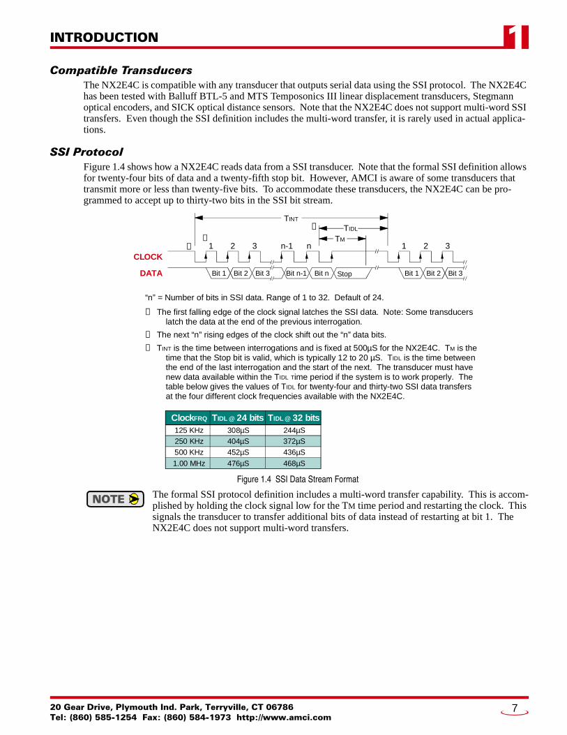
SSI ProtocolFigure 1.4 shows how a NX2E4C reads data from a SSI transducer. Note that the formal SSI definition allows for twenty-four bits of data and a twenty-fifth stop bit. However, AMCI is aware of some transducers that transmit more or less than twenty-five bits. To accommodate these transducers, the NX2E4C can be pro-grammed to accept up to thirty-two bits in the SSI bit stream.
Figure 1.4 SSI Data Stream Format
The formal SSI protocol definition includes a multi-word transfer capability. This is accom-plished by holding the clock signal low for the TM time period and restarting the clock. This signals the transducer to transfer additional bits of data instead of restarting at bit 1. The NX2E4C does not support multi-word transfers.
1 2 3 n-1 n 1 2 3
Bit n-1 Bit n StopBit 1 Bit 2 Bit 3 Bit 1 Bit 2 Bit 3
CLOCK
DATA
➀➁
➂TINT
TIDL
➀ The first falling edge of the clock signal latches the SSI data. Note: Some transducers latch the data at the end of the previous interrogation.
➁ The next “n” rising edges of the clock shift out the “n” data bits.
➂ TINT is the time between interrogations and is fixed at 500µS for the NX2E4C. TM is the time that the Stop bit is valid, which is typically 12 to 20 µS. TIDL is the time between the end of the last interrogation and the start of the next. The transducer must have new data available within the TIDL Time period if the system is to work properly. The table below gives the values of TIDL for twenty-four and thirty-two SSI data transfers at the four different clock frequencies available with the NX2E4C.
ClockFRQ TIDL @ 24 bits TIDL @ 32 bits 125 KHz 308µS 244µS 250 KHz 404µS 372µS 500 KHz 452µS 436µS
1.00 MHz 476µS 468µS
TM
“n” = Number of bits in SSI data. Range of 1 to 32. Default of 24.
20 Gear Drive, Plymouth Ind. Park, Terryville, CT 06786Tel: (860) 585-1254 Fax: (860) 584-1973 http://www.amci.com
7

INTRODUCTION1
Programmable ParametersThe NX2E4C is configured by programming its Programmable Parameters. These parameters are broken down into two groups.
SSI Setup Parameters – Six parameters that are used to extract the SSI Data Value from the bit stream. These parameters define the clock speed of the data transfer, the position and length of the SSI data within the bit stream, and the format of the data.
Data Setup Parameters – Six parameters that affect the Data Value and Rate of Change information. These parameters allow you to scale the Data Value, preset it to a programmable count, and set the update time of the Rate of Change information. The parameter that enables the unit’s Status LED’s is also included with these parameters.
Each channel has its own set of parameters.
SSI Setup Parameters
SSI Clock FrequencyThis parameter allows you to set the SSI clock frequency for the channel to one of four values: 125 KHz, 250 KHz, 500 KHz, or 1.000 MHz.
The default value of 1 MHz will work in most applications. Setting the clock frequency to 1 MHz yields the longest idle times between interrogations. However, your transducer may not be able to operate at 1 MHz. Consult your transducer documentation to determine its maximum operating frequency. Remember that the maximum SSI clock frequency is also dependent on the length of the transducer cable.
Number of SSI BitsThis value sets the number of bits that the NX2E4C will read from the SSI transducer per interrogation. The parameters default value of twenty-four will work in most cases. You can set this parameter to any value between 1 and 32.
Number of Data Bits &MSB Number Parameters
As the examples show in figure 1.5, these two parameters tell the NX2E4C where the SSI data is embedded in the data stream. The Number of Data Bits parameter specifies the length of the data and the MSB Number parameter specifies the bit that starts the SSI data. The default value of the MSB Number parameter is one. The default value for the Number of Data Bits parameter is twenty-four.
Figure 1.5 Embedded Data Value
Refer to the documentation that came with your transducer to determine where the SSI data is located in the SSI data stream. If you are using a Balluff LDT, the default values should work correctly. If you are using a MTS LDT, Set the Number of Data Bits equal to the LDT’s number of bits and the MSB Number to one.
1 2 3 4 5 6 7 8 9 10 11 12 13 14 15 16 17 18 19 20 21 22 23 24
SSI DATA BITS
16 Bit Data Value Number of Data Bits = 16MSB Number = 9
20 Bit Data ValueNumber of Data Bits = 20
MSB Number = 1
n-1 n
Maximum Value of “n” is 32
ADVANCED MICRO CONTROLS INC.8

INTRODUCTION 1
SSI Setup Parameters (continued)Data TypeThis parameter tells the NX2E4C to interpret the SSI data as a binary number or a gray code number. The default value is Binary.
Data LogicThis parameter is included to handle situations where the SSI data is reported with negative logic. If this parameter is set, the NX2E4C will invert the data bits before performing any scaling. The default value is Positive. When this parameter is left at its default value, the NX2E4C will use the SSI data as it is from the transducer.
Appendix A, COMMON CONFIGURATIONS, starting on page 37 lists several SSI transducers along with the parameter values that should be used to extract the data value from the bit stream. The appendix also gives hints on how to determine the correct values if you only know the number of bits in the data stream.
Data Setup ParametersOnce the NX2E4C has extracted the SSI data from the SSI data stream, it uses the Data Setup Parameters to convert the raw SSI data into the Data Value it reports to the network. The formula for determining the Data Value is:
Data Value = SSI Data * (MUL / DIV) + LO
where: MUL = Scalar Multiplier DIV = Scalar Divisor LO = Linear Offset. The Linear Offset is an internal parameter that normally
equals zero. The Linear Offset is changed when you preset the Data Value.
Scalar Multiplier &Scalar Divisor
These two parameters are use to scale the SSI data. Both parameters have a default value of one and can range in value from 1 to 32,767. The Scalar Multiplier must be less than or equal to the Scalar Divisor. In other words, the ratio of Multiplier to Divisor cannot be greater than one.
Linear displacement transducers from Balluff and MTS have resolutions measured in µm/count. The NX2E4C can easily convert to the more familiar US Customary system of inches. The figure below shows the Multiplier and Divisor values needed to convert from various metric resolutions to US Customary resolu-tions. For example, to convert data from a LDT with 5µm/count resolution to 0.0005"/count resolution, use a Multiplier of 50 and a Divisor of 127.
Figure 1.6 Scalar Values for Linear Measurement Conversion
125127
0.0002"
50127
0.0005"
25127
0.001"
25254
0.002"
5127
0.005"
100127
50127
25127
10127
100127
50127
20127
100127
40127
5 µm
10 µm
20 µm
40 µmLDT
Res
olu
tion
Desired Resolution
= Desired resolutionexceeds resolutionof LDT.
20 Gear Drive, Plymouth Ind. Park, Terryville, CT 06786Tel: (860) 585-1254 Fax: (860) 584-1973 http://www.amci.com
9

INTRODUCTION1
Data Setup Parameters (continued)Preset ValueThe Preset Value parameter gives you the ability to offset the Data Value. When you preset the Data Value, the NX2E4C calculates an internal parameter called the Linear Offset. The Linear Offset is the value needed to make the Data Value equal to the Preset Value. The default Preset Value is zero. Its range is ±268,435,455.
1) Programming this parameter does not change the Data Value. There is a separate command for presetting the Data Value to the Preset Value.
2) The NX2E4C will issue a Preset Value Error message if you attempt to program aPreset Value that is outside its range of ±268,435,455.
3) When the Data Value is preset, the NX2E4C calculates a Linear Offset that it then applies to the Data Value. The only way to erase the linear offset is to re-program the Preset Value parameter.
4) Presetting the Data Value generates a linear offset. If you are using arotary encoder and wish to preset the position, see Appendix B, WORKING WITH ROTARY ENCODERS, starting on page 41.
Count DirectionThis parameter is useful if your Data Value represents a linear position. It gives you the ability to reverse the direction of motion needed to increase the position count. For simplicity’s sake, the two values for this parameter are called Positive Direction and Negative Direction. When this parameter is set to its default of Positive, the Data Value is not changed. When this parameter is set to Negative, the Data Value is multiplied by -1 before it is reported. For linear transducers, this has the effect of reversing the direction of motion needed to increase the count. When using LDT’s and the Count Direction is set to Positive, the Data Value usually increases as the magnet moves away from the head of the LDT. When the Count Direction is set to Negative, the Data Value increases as the magnet moves towards the head of the LDT.
You will need to preset the Data Value after you program the Count Direction parameter.
If your Data Value represents a rotary position, you cannot change the count direction with this parameter. However, you can easily reverse the count direction with ladder logic as shown in Appendix B, WORKING WITH ROTARY ENCODERS, starting on page 41.
Rate Update TimeThe Rate Update Time sets the amount of time between Rate of Change information updates to the network. Its can be set to either 24 milliseconds or 160 milliseconds, with 160 milliseconds being the default. Decrease the time between updates for faster response to changes in this value. Increase the time between updates for better averaging of this value. Note that the Rate Update Time is quantitated to the network update time. For example, if you set the Rate Update Time to 24 milliseconds and the network scan time to 10 milliseconds, then the Rate of Change will update every 24 milliseconds, but you will see a change in this value at 30, 50, 80, 100, and 120 milliseconds, etc.
LED EnableThis parameter gives you the ability to enable or disable the Unit Status LED of the corresponding Sensor Input Channel. When disabled, the LED is always off and does not show the status of the NX2E4C. See page 6 for a description of the Unit Status LED’s.
ADVANCED MICRO CONTROLS INC.10

INTRODUCTION 1
Backplane ProgrammingA NX2E4C is programmed over the network through the input and output words assigned to it. Because these words are constantly updated, the unit implements a simple hand-shaking protocol to control when it accepts new programming data. This hand-shaking protocol is called a Programming Cycle.
Programming CycleA Programming cycle consists of six steps and is controlled by the Transmit Bit in the output data words and the Acknowledge Bit in the input data words.
1) Write the new programming data into the output data words with the Transmit Bit reset. This step insures that the correct data is in the output data words before the Programming Cycle begins.
2) Set the Transmit bit. A Programming Cycle is initiated when this bit makes a 0 1 transition.
3) Once the unit is done with the programming data, it will set any necessary error bits and the Acknowledge Bit in its input data words.
4) Once you see the Acknowledge Bit set, check for any errors. The error bits are only valid while the Acknowledge Bit is set.
5) Respond to any errors and reset the Transmit Bit.
6) The NX2E4C responds by resetting the Acknowledge Bit. The Programming Cycle is complete.
EEPROM Parameter MemoryParameter values are stored in a non-volatile EEPROM memory. This memory type can store parameter val-ues in the absence of power for over twenty years, but you can only write to it a limited number of times before it will be damaged. The EEPROM that AMCI uses is guaranteed for a minimum of 100,000 write cycles.
Every time you preset the Data Value, the NX2E4C calculates an offset and stores this value in the EEPROM. If your application requires you to continuously preset the Data Value, consider doing this in the PLC instead of the NX2E4C. Starting on page 42, Appendix B has a section entitled Offsetting the Data Value, which gives you suggestions and a sample ladder logic pro-gram for presetting the Data Value in the PLC.
20 Gear Drive, Plymouth Ind. Park, Terryville, CT 06786Tel: (860) 585-1254 Fax: (860) 584-1973 http://www.amci.com
11

INTRODUCTION1
NotesADVANCED MICRO CONTROLS INC.12

20 Gear Drive, Plymouth IndTel: (860) 585-1254 Fax: (8
CHAPTER 2
INSTALLATIONGeneral GuidelinesWhen wiring any control system, these guidelines must be followed to prevent electromagnetic interference and ground loops:
WiringTransducer signals are generally low voltage, low power signals. If you are using A-B guidelines for cabling installation, treat the transducer cable as a Category 2 cable. It can be installed in conduit along with other low power cabling such as communication cables and low power ac/dc I/O lines. It cannot be installed in conduit with ac power lines or high power ac/dc I/O lines.Like all signal and communication cable, the transducer cable should be shielded. The shield must be grounded at one end only, typically at the input to the NX2E4C. If a junction must be made in the signal cable, treat the shield as a signal-carrying conductor. Do not connect the shield to ground at any junction box or the transducer. If the signal cable must cross power feed lines, it should do so at right angles.Route at least five feet from high voltage enclosures, or sources of “rf” radiation.
GroundingAll ground connections must be permanent and continuous to provide a low-impedance path to earth ground for induced noise currents. The chassis of the NX2E4C must be connected to chassis ground through a grounding wire connected to the ground connection of the power supply connector. Any sensor or power supply that is attached to the NX2E4C must be connected to the same chassis ground as the unit to avoid ground loops. All isolation transformer secondary windings must be grounded to the same earth ground as the machine ground.
Surge SuppressionSurge suppression devices should be placed across the coil of an inductive device to reduce the effects of high voltage transients (i.e., varistors, diodes, etc.). This includes any inductive load that is powered by the same supply used to power the NX2E4C or its sensors.
MountingIf mounting a NX2E4C on an enclosure door, do not rely on the hinge to make a good electrical connec-tion between the door and the enclosure. A bonding wire from the door to the rest of the enclosure must be installed.
Required Power SupplyThe NX2E4C draws its power from an external DC supply. The output voltage of the supply must be between 20 and 30 Vdc and it must be able to provide a minimum of 12 watts of power. This translates into 0.50Adc @ 24Vdc. A separate power supply can be used for the NX2E4C, or power can be drawn from a system supply.
If a separate supply is used, it should be mounted relatively close to the unit. If a system sup-ply is used, this supply must not be used to switch large inductive loads such as relays or sole-noids without proper surge suppression devices installed on these loads.
If your SSI transducer is also powered from a 24Vdc supply, then you can use the NX2E4C to power it. Add the transducers’ current requirements to the 0.50A required by the NX2E4C when sizing the supply.
. Park, Terryville, CT 0678660) 584-1973 http://www.amci.com
13
INSTALLATION2
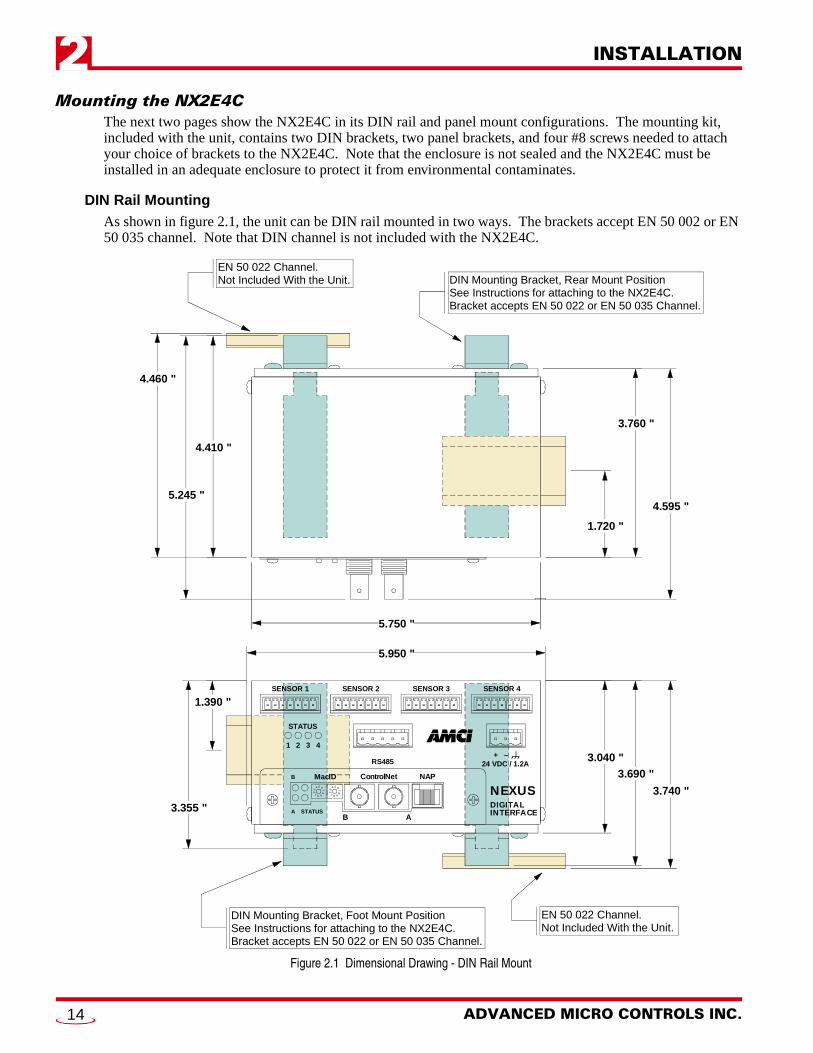
Mounting the NX2E4CThe next two pages show the NX2E4C in its DIN rail and panel mount configurations. The mounting kit, included with the unit, contains two DIN brackets, two panel brackets, and four #8 screws needed to attach your choice of brackets to the NX2E4C. Note that the enclosure is not sealed and the NX2E4C must be installed in an adequate enclosure to protect it from environmental contaminates.
DIN Rail MountingAs shown in figure 2.1, the unit can be DIN rail mounted in two ways. The brackets accept EN 50 002 or EN 50 035 channel. Note that DIN channel is not included with the NX2E4C.
Figure 2.1 Dimensional Drawing - DIN Rail Mount
3.040 "3.690 "
3.740 "
1.390 "
3.355 "
1.720 "
3.760 "
4.595 "
4.410 "
4.460 "
5.750 "
5.950 "
EN 50 022 Channel.Not Included With the Unit.
DIN Mounting Bracket, Foot Mount PositionSee Instructions for attaching to the NX2E4C.Bracket accepts EN 50 022 or EN 50 035 Channel.
DIN Mounting Bracket, Rear Mount PositionSee Instructions for attaching to the NX2E4C.Bracket accepts EN 50 022 or EN 50 035 Channel.
EN 50 022 Channel.Not Included With the Unit.
5.245 "
B
A STATUS
MacID ControlNet NAP
B A
1
STATUS
RS485
NEXUSDIGITALINTERFACE
0 1 2
3
4 5 6 7 8 9 0 1 2
3
4 5 6 7 8 9
2 3 4
SENSOR 4SENSOR 3SENSOR 2SENSOR 1
24 VDC / 1.2A+ –
ADVANCED MICRO CONTROLS INC.14
INSTALLATION 2
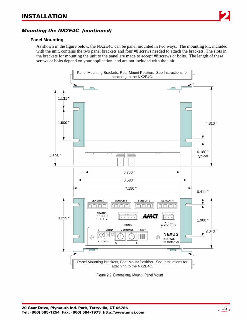
Mounting the NX2E4C (continued)Panel MountingAs shown in the figure below, the NX2E4C can be panel mounted in two ways. The mounting kit, included with the unit, contains the two panel brackets and four #8 screws needed to attach the brackets. The slots in the brackets for mounting the unit to the panel are made to accept #8 screws or bolts. The length of these screws or bolts depend on your application, and are not included with the unit.
Figure 2.2 Dimensional Mount - Panel Mount
1.131 "
1.900 "
5.750 "
3.040 "
0.411 "7.150 "
6.580 "
3.255 "1.900 "
4.595 "
4.810 "
Panel Mounting Brackets, Rear Mount Position. See Instructions forattaching to the NX2E4C.
Panel Mounting Brackets, Foot Mount Position. See Instructions forattaching to the NX2E4C.
0.180 "typical
B
A STATUS
MacID ControlNet NAP
B A
1
STATUS
RS485
NEXUSDIGITALINTERFACE
0 1 2
3
4 5 6 7 8 9 0 1 2
3
4 5 6 7 8 9
2 3 4
SENSOR 4SENSOR 3SENSOR 2SENSOR 1
24 VDC / 1.2A+ –
20 Gear Drive, Plymouth Ind. Park, Terryville, CT 06786Tel: (860) 585-1254 Fax: (860) 584-1973 http://www.amci.com
15
INSTALLATION2
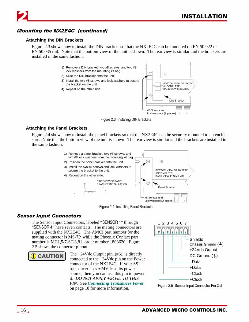
Mounting the NX2E4C (continued)Attaching the DIN BracketsFigure 2.3 shows how to install the DIN brackets so that the NX2E4C can be mounted on EN 50 022 or EN 50 035 rail. Note that the bottom view of the unit is shown. The rear view is similar and the brackets are installed in the same fashion.
Figure 2.3 Installing DIN Brackets
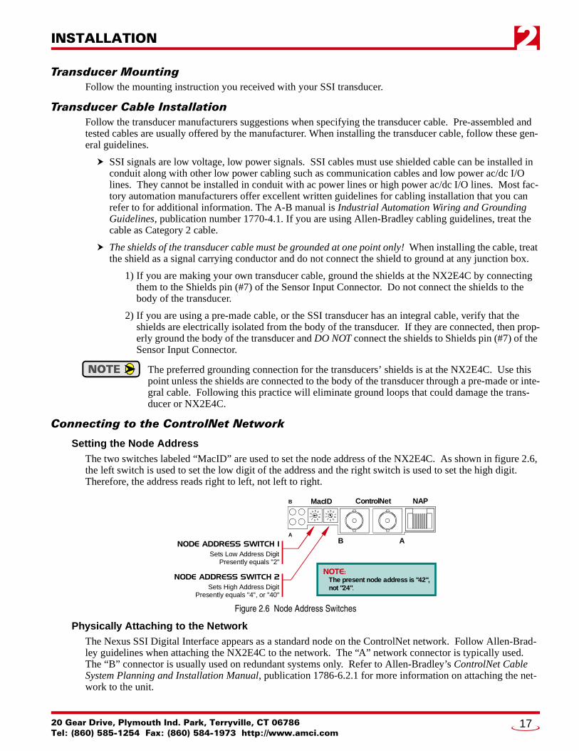
Attaching the Panel BracketsFigure 2.4 shows how to install the panel brackets so that the NX2E4C can be securely mounted to an enclo-sure. Note that the bottom view of the unit is shown. The rear view is similar and the brackets are installed in the same fashion.
Figure 2.4 Installing Panel Brackets
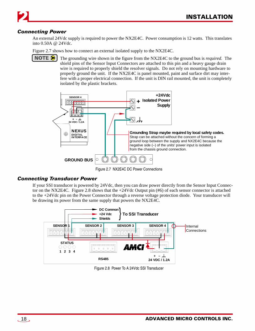
Sensor Input ConnectorsThe Sensor Input Connectors, labeled “SENSOR 1” through “SENSOR 4” have seven contacts. The mating connectors are supplied with the NX2E4C. The AMCI part number for the mating connector is MS-7P, while the Phoenix Contact part number is MC1,5/7-ST-3,81, order number 1803620. Figure 2.5 shows the connector pinout.
The +24Vdc Output pin, (#6), is directly connected to the +24Vdc pin on the Power connector of the NX2E4C. If your SSI transducer uses +24Vdc as its power source, then you can use this pin to power it. DO NOT APPLY +24Vdc TO THIS PIN. See Connecting Transducer Power on page 18 for more information.
1) Remove a DIN bracket, two #8 screws, and two #8 lock washers from the mounting kit bag.
2) Slide the DIN bracket onto the unit.
3) Install the two #8 screws and lock washers to secure the bracket on the unit.
4) Repeat on the other side.
#8 Screws andLockwashers (2 places)
DIN Bracket
BOTTOM VIEW OF NX2E4C(INCOMPLETE)BACK VIEW IS SIMILIAR
1) Remove a panel bracket, two #8 screws, and two #8 lock washers from the mounting kit bag.
2) Position the panel bracket onto the unit.
3) Install the two #8 screws and lock washers to secure the bracket to the unit.
4) Repeat on the other side.
#8 Screws andLockwashers (2 places)
Panel Bracket
BOTTOM VIEW OF NX2E4C(INCOMPLETE)BACK VIEW IS SIMILIAR
SIDE VIEW OF PANELBRACKET INSTALLATION
Figure 2.5 Sensor Input Connector Pin Out
ShieldsChassis Ground ( ) +24Vdc Output DC Ground ( ) –Data+Data–Clock+Clock
1 2 3 4 5 6 7
ADVANCED MICRO CONTROLS INC.16
INSTALLATION 2
Transducer MountingFollow the mounting instruction you received with your SSI transducer.
Transducer Cable InstallationFollow the transducer manufacturers suggestions when specifying the transducer cable. Pre-assembled and tested cables are usually offered by the manufacturer. When installing the transducer cable, follow these gen-eral guidelines.
SSI signals are low voltage, low power signals. SSI cables must use shielded cable can be installed in conduit along with other low power cabling such as communication cables and low power ac/dc I/O lines. They cannot be installed in conduit with ac power lines or high power ac/dc I/O lines. Most fac-tory automation manufacturers offer excellent written guidelines for cabling installation that you can refer to for additional information. The A-B manual is Industrial Automation Wiring and Grounding Guidelines, publication number 1770-4.1. If you are using Allen-Bradley cabling guidelines, treat the cable as Category 2 cable.
The shields of the transducer cable must be grounded at one point only! When installing the cable, treat the shield as a signal carrying conductor and do not connect the shield to ground at any junction box.
1) If you are making your own transducer cable, ground the shields at the NX2E4C by connecting them to the Shields pin (#7) of the Sensor Input Connector. Do not connect the shields to the body of the transducer.
2) If you are using a pre-made cable, or the SSI transducer has an integral cable, verify that the shields are electrically isolated from the body of the transducer. If they are connected, then prop-erly ground the body of the transducer and DO NOT connect the shields to Shields pin (#7) of the Sensor Input Connector.
The preferred grounding connection for the transducers’ shields is at the NX2E4C. Use this point unless the shields are connected to the body of the transducer through a pre-made or inte-gral cable. Following this practice will eliminate ground loops that could damage the trans-ducer or NX2E4C.
Connecting to the ControlNet Network
Setting the Node AddressThe two switches labeled “MacID” are used to set the node address of the NX2E4C. As shown in figure 2.6, the left switch is used to set the low digit of the address and the right switch is used to set the high digit. Therefore, the address reads right to left, not left to right.
Figure 2.6 Node Address Switches
Physically Attaching to the NetworkThe Nexus SSI Digital Interface appears as a standard node on the ControlNet network. Follow Allen-Brad-ley guidelines when attaching the NX2E4C to the network. The “A” network connector is typically used. The “B” connector is usually used on redundant systems only. Refer to Allen-Bradley’s ControlNet Cable System Planning and Installation Manual, publication 1786-6.2.1 for more information on attaching the net-work to the unit.
B
A
MacID ControlNet NAP
B A
0 1 2
3
4 5 6 7 8 9 0 1 2
3
4 5 6 7 8 9
NODE ADDRESS SWITCH 1 Sets Low Address Digit
Presently equals "2"
NODE ADDRESS SWITCH 2 Sets High Address Digit
Presently equals "4", or "40"
NOTE: The present node address is "42", not "24".
20 Gear Drive, Plymouth Ind. Park, Terryville, CT 06786Tel: (860) 585-1254 Fax: (860) 584-1973 http://www.amci.com
17
INSTALLATION2
Connecting PowerAn external 24Vdc supply is required to power the NX2E4C. Power consumption is 12 watts. This translates into 0.50A @ 24Vdc.
Figure 2.7 shows how to connect an external isolated supply to the NX2E4C.
The grounding wire shown in the figure from the NX2E4C to the ground bus is required. The shield pins of the Sensor Input Connectors are attached to this pin and a heavy gauge drain wire is required to properly shield the resolver signals. Do not rely on mounting hardware to properly ground the unit. If the NX2E4C is panel mounted, paint and surface dirt may inter-fere with a proper electrical connection. If the unit is DIN rail mounted, the unit is completely isolated by the plastic brackets.
Figure 2.7 NX2E4C DC Power Connections
Connecting Transducer PowerIf your SSI transducer is powered by 24Vdc, then you can draw power directly from the Sensor Input Connec-tor on the NX2E4C. Figure 2.8 shows that the +24Vdc Output pin (#6) of each sensor connector is attached to the +24Vdc pin on the Power Connector through a reverse voltage protection diode. Your transducer will be drawing its power from the same supply that powers the NX2E4C.
Figure 2.8 Power To A 24Vdc SSI Transducer
24 VDC / 1.2A+ –
NEXUSDIGITALINTERFACE
SENSOR 4
+ –
GROUND BUS
+24VdcIsolated Power
Supply
Grounding Strap maybe required by local safety codes.Strap can be attached without the concern of forming a ground loop between the supply and NX2E4C because the negative side (–) of the units' power input is isolated from the chassis ground connection.
1
STATUS
RS485 24 VDC / 1.2A+ –
2 3 4
SENSOR 4SENSOR 3SENSOR 2SENSOR 1
DC Common+24 Vdc To SSI TransducerShields
Internal Connections
ADVANCED MICRO CONTROLS INC.18
INSTALLATION 2
Connecting Transducer Power (continued)If your transducer does not use +24Vdc for power, then you must use an external supply with the correct volt-age output and current rating. As shown in figure 2.9 below, you must connect your power supply’s common pin to the DC Ground pin (#5) of the Sensor Input Connector on the NX2E4C before the transducer will work correctly. Figure 2.9 also shows how to properly ground a system that uses two power supplies.
Figure 2.9 Power To A Non-24Vdc SSI Transducer
You must attach all supplies to the same ground bus, preferably to the same or adjacent studs on the bus. If you attach the supplies to different grounding points, you run a very strong risk of creating a ground loop that can damage the NX2E4C or sensors.This procedure is even more important if local codes require you attach grounding straps from the supplies Chassis Ground pin to the DC Common pin.
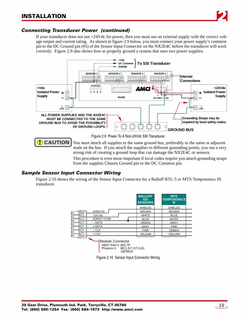
Sample Sensor Input Connector WiringFigure 2.10 shows the wiring of the Sensor Input Connector for a Balluff BTL-5 or MTS Temposonics III transducer.
Figure 2.10 Sensor Input Connector Wiring
1
STATUS
RS485 24 VDC / 1.2A+ –
2 3 4
SENSOR 4SENSOR 3SENSOR 2SENSOR 1
+VdcDC Common To SSI TransducerShields
GROUND BUS
+24VdcIsolated Power
Supply
Grounding Straps may be required by local safety codes.
+VdcIsolated PowerSupply
ALL POWER SUPPLIES AND THE NX2E4CMUST BE CONNECTED TO THE SAME
GROUND BUS TO AVOID THE POSSIBILITYOF GROUND LOOPS.
Internal Connections
SHIELDSSHIELDS SHIELDS
Module Connector AMCI Part #: MS-7P Phoenix #: MC1,5/7-ST-3,81 1803620
BALLUFFSSI
SENSORS
MTSTEMPOSONICS
III
7
6
5
4
3
2
1
– DATA+– DATA– CLK+ CLK
SUPPLY COMGREENGRAYPINK
YELLOW
WHITEBLUE
GRAYPINK
GREENYELLOW
BLUEWHITE
+24 VdcBROWN BROWN
20 Gear Drive, Plymouth Ind. Park, Terryville, CT 06786Tel: (860) 585-1254 Fax: (860) 584-1973 http://www.amci.com
19

INSTALLATION2
NotesADVANCED MICRO CONTROLS INC.20
20 Gear Drive, Plymouth IndTel: (860) 585-1254 Fax: (8
CHAPTER 3
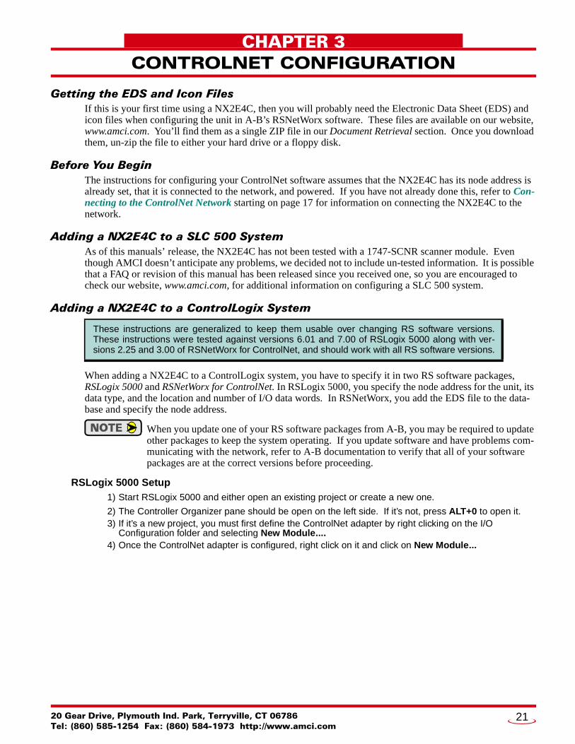
CONTROLNET CONFIGURATIONGetting the EDS and Icon FilesIf this is your first time using a NX2E4C, then you will probably need the Electronic Data Sheet (EDS) and icon files when configuring the unit in A-B’s RSNetWorx software. These files are available on our website, www.amci.com. You’ll find them as a single ZIP file in our Document Retrieval section. Once you download them, un-zip the file to either your hard drive or a floppy disk.
Before You BeginThe instructions for configuring your ControlNet software assumes that the NX2E4C has its node address is already set, that it is connected to the network, and powered. If you have not already done this, refer to Con-necting to the ControlNet Network starting on page 17 for information on connecting the NX2E4C to the network.
Adding a NX2E4C to a SLC 500 SystemAs of this manuals’ release, the NX2E4C has not been tested with a 1747-SCNR scanner module. Even though AMCI doesn’t anticipate any problems, we decided not to include un-tested information. It is possible that a FAQ or revision of this manual has been released since you received one, so you are encouraged to check our website, www.amci.com, for additional information on configuring a SLC 500 system.
Adding a NX2E4C to a ControlLogix System
When adding a NX2E4C to a ControlLogix system, you have to specify it in two RS software packages, RSLogix 5000 and RSNetWorx for ControlNet. In RSLogix 5000, you specify the node address for the unit, its data type, and the location and number of I/O data words. In RSNetWorx, you add the EDS file to the data-base and specify the node address.
When you update one of your RS software packages from A-B, you may be required to update other packages to keep the system operating. If you update software and have problems com-municating with the network, refer to A-B documentation to verify that all of your software packages are at the correct versions before proceeding.
RSLogix 5000 Setup1) Start RSLogix 5000 and either open an existing project or create a new one.
2) The Controller Organizer pane should be open on the left side. If it’s not, press ALT+0 to open it.3) If it’s a new project, you must first define the ControlNet adapter by right clicking on the I/O
Configuration folder and selecting New Module....4) Once the ControlNet adapter is configured, right click on it and click on New Module...
These instructions are generalized to keep them usable over changing RS software versions.These instructions were tested against versions 6.01 and 7.00 of RSLogix 5000 along with ver-sions 2.25 and 3.00 of RSNetWorx for ControlNet, and should work with all RS software versions.
. Park, Terryville, CT 0678660) 584-1973 http://www.amci.com
21

CONTROLNET CONFIGURATION3
Adding a NX2E4C to a ControlLogix System (continued)RSLogix 5000 Setup (continued)
5) Define the NX2E4C as a generic CONTROLNET-MODULE. Click OK and define the properties as follows:
† If you are not using all of the sensor input channels then you can decrease the number of scanned input words from its default of thirty. Refer to ControlLogix Input Data Format on page 28 to determine the number of words needed. Remember that the numbering of the words begins at zero, so add one to the number of the last word that you need before entering it in the properties table. Even though you can change the number of words, AMCI suggests leaving it at its default of thirty to help keep your setup compatible with potential future releases of the NX2E4C.
‡ If you are not using all of the sensor input channels, then you can decrease the number of output words from its default of thirty-three. Refer to Output Data Words on page 25 to determine the number of words needed. Remember that the numbering of the words begins at zero, so add one to the number of the last word that you need before entering it in the properties table. Even though you can change the number of words, AMCI suggests leaving the number of words at its default to help keep your setup compatible with potential future releases of the NX2E4C.
6) Click Next> and define the RPI. The minimum value is 5.0 milliseconds.
7) Click Finish.
8) Save the project.
9) Download the new configuration to the processor.
RSNetWorx Setup1) Start RSNetWorx for ControlNet and either open an existing project or create a new one.
2) If this is the first time using a NX2E4C, you will probably need to register the EDS file. If you haven’t downloaded the EDS and icon file from our website, refer to Getting the EDS and Icon Files on page 21 for instructions. Once you have the EDS file, register the NX2E4C by clicking on the Tools menu, followed by EDS Wizard... and following the instructions. The name of the EDS file is NX2E4C_r01.eds.
3) Click the icon to go online. RSNetWorx will scan the ControlNet network and should discover the NX2E4C at the node address you set with the rotary switches and specified in the RSLogix 5000 software.
4) Click on the Enable Edits checkbox and then save the project.
At this point, check the ControlNet Status LED’s on the unit. The Unit Status and Adapter Status LED’s should both be on solid green. The Channel A/B Status LED’s should also be on solid green if they have a physical network connection. No LED’s should be blinking red.
If the status LED’s are OK, bring up the RSLogix 5000 software. Select the Logic menu, followed by Moni-tor Tags. The data associated with the NX2E4C is available under the name you chose when configuring it. For example, if you chose a name of “SSINexusNode” in step 5 of the RSLogix 5000 Setup, the input data is available under SSINexusNode:I SSINexusNode:I.Data SSINexusNode:I.Data[0-29]. Similarly, the output data is available under the SSINexusNode:O tree.
Name: Your ChoiceDescription: Your Choice
Comm Format: Data-INTNode: Set it to the same value as the Node Address of the NX2E4C.
Assembly Instance Size
Input: 100 30†
Output: 150 33‡
Configuration: 110 0
ADVANCED MICRO CONTROLS INC.22

CONTROLNET CONFIGURATION 3
Adding a NX2E4C to a PLC-5 SystemWhen adding a NX2E4C to a PLC-5 system, you have to specify the unit in the RSNetWorx for ControlNet software. In RSNetWorx, you add the EDS file to the database and specify the node address. After that, you modify the scanlist to communicate with the NX2E4C.
When you update one of your RS software packages from A-B, you may be required to update other packages to keep the system operating. If you update software and have any problems, refer to A-B documentation to verify that your software packages are all at the correct versions before proceeding.
RSNetworx Setup1) After connecting the NX2E4C to the network and applying power, start RSNetworx and either open
an existing project or create a new one.
2) If this is the first time using a NX2E4C, you will probably need to register the EDS file. If you haven’t downloaded the EDS and icon file from our website, refer to Getting the EDS and Icon Files on page 21 for instructions. Once you have the EDS file, register the NX2E4C by clicking on the Tools menu, followed by EDS Wizard... and following the instructions. The name of the EDS file is NX2E4C_r01.eds.
3) Click the icon to go online. The network is searched, and the NX2E4C will appear as an “Extra device” at the node selected with the rotary switches.
4) Click the Enable Edits checkbox and choose “Use online data (upload)”. Click OK. At this point, you can right click on the NX2E4C icon and select Properties from the pop-up menu. In the properties window, you can change the name associated with the unit and add a description.
5) Go offline by clicking the icon and save the changes to the project.
6) Click the Enable Edits checkbox and then right click on the PLC-5 icon. Click on Scanlist Configuration in the pop-up menu.
7) In the Device Name column, right click on the name of the unit, (NX2E4C by default), and click on Insert Connection in the pop-up menu. The Connection Properties window appears on the screen. A sample Connection Properties window is shown in figure 3.1
8) If needed, set the Input Size and Input Address of the Data Input File. This file, N9 in the figure, resides in the PLC-5 and is used by all of the ControlNet nodes. Therefore, it must be large enough to hold all of the input data on the network.If you are not using all of the sensor input channels, then you can decrease the number of scanned input words from its default of twenty-eight. Refer to PLC-5 Input Data Format on page 29 to determine the number of words needed. Remember that the numbering of the words begins at zero, so add one to the number of the last word that you need before entering it in the properties table. Even though you can change the number of words, AMCI suggests leaving it at its default of twenty-eight to help keep your setup compatible with potential future releases of the NX2E4C.
These instructions are generalized to keep them usable over changing RS software versions fromAllen-Bradley. These instructions were tested against versions 2.25 and 3.00 of RSNetWorx forControlNet and should work with all RS software versions.
Figure 3.1 Scanlist Configuration Screen
20 Gear Drive, Plymouth Ind. Park, Terryville, CT 06786Tel: (860) 585-1254 Fax: (860) 584-1973 http://www.amci.com
23

CONTROLNET CONFIGURATION3
Adding a NX2E4C to a PLC-5 System (continued)RSNetworx Setup (continued)
9) If needed, set the Output Size and Output Address of the Data Output File. This file, N10 in the figure, resides in the PLC-5 and is used by all of the ControlNet nodes. Therefore, it must be large enough to hold all of the output data on the network. If you are not using all of the sensor input channels, then you can decrease the number of output words. Refer to Output Data Words on page 25 to determine the number of words needed. Remember that the numbering of the words begins at zero, so add one to the number of the last word that you need before entering it in the properties table. Even though you can change the number of words, AMCI suggests leaving the number of words at its default of thirty-three to help keep your setup compatible with potential future releases of the NX2E4C.
10) Set the Request Packet Interval time. This has a minimum acceptable value of five milliseconds.
11) Click OK to close the Connection Properties window. In the Scanlist Configuration window, save the changes and close the window.
12) Click the icon to go online. Click on Network in the toolbar and then click Download to Network.
At this point, check the ControlNet Status LED’s on the unit. The Unit Status and Adapter Status LED’s should both be on solid green. The Channel A/B Status LED’s should also be on solid green if they have a physical network connection. No LED’s should be blinking red.
If the status LED’s are OK, bring up the RSLogix 5 software. The input data will be at the address you spec-ified when configuring the Scanlist Properties. (Step 8 above.)
ADVANCED MICRO CONTROLS INC.24

20 Gear Drive, Plymouth IndTel: (860) 585-1254 Fax: (8
CHAPTER 4
DATA FORMAT & PROGRAMMINGOutput Data WordsThe thirty-three output data words are written from the ControlNet controller to the NX2E4C to program the four input channels and preset the Data Values. Figure 4.1 shows the format of the this data. Note that it starts with a Con-trol Word followed by four block of identical data, one block for each input channel.
If you are using the NX2E4C to interface with less than four transducers then, when you con-figure the network as described in chapter 3, you can set the number of data words to only use the blocks necessary. Inter-nally, the NX2E4C automati-cally fills in any data word that is not transmitted to it with a value of zero, so the program-ming block will still work cor-rectly.
Preset Value FormatWhen programming, the Preset Values can be ±268,435,455. Therefore, this parameter requires two words to hold its data. The lower four digits of the value are stored in the second word. The upper five digits are stored in the first word. For example, a Preset Value of 123,456,789 would be stored as 12345 in the first word and 6789 in the second.
Negative values are transmitted in sign-magni-tude format. The MSB of the Preset Value’s first word contains the sign bit. To enter a neg-ative value, set the data table radix to decimal and enter the absolute value of the parameter. Next, switch the radix to binary and set the MSB of the first word.
Word # Programming Data
0 Control Word
1 CH1: Configuration Word
2 CH1: Number of SSI Bits
3 CH1: MSB Number
4 CH1: Number of Data Bits
5 CH1: Scalar Multiplier
6 CH1: Scalar Divisor
7 CH1: Sign + Upper 5 digits of Preset Value
8 CH1: Lower 4 Digits of Preset Value
9 CH2: Configuration Word
10 CH2: Number of SSI Bits
11 CH2: MSB Number
12 CH2: Number of Data Bits
13 CH2: Scalar Multiplier
14 CH2: Scalar Divisor
15 CH2: Sign + Upper 5 digits of Preset Value
16 CH2: Lower 4 Digits of Preset Value
17 CH3: Configuration Word
18 CH3: Number of SSI Bits
19 CH3: MSB Number
20 CH3: Number of Data Bits
21 CH3: Scalar Multiplier
22 CH3: Scalar Divisor
23 CH3: Sign + Upper 5 digits of Preset Value
24 CH3: Lower 4 Digits of Preset Value
25 CH4: Configuration Word
26 CH4: Number of SSI Bits
27 CH4: MSB Number
28 CH4: Number of Data Bits
29 CH4: Scalar Multiplier
30 CH4: Scalar Divisor
31 CH4: Sign + Upper 5 digits of Preset Value
32 CH4: Lower 4 Digits of Preset Value
Figure 4.1 Programming Data Format
. Park, Terryville, CT 0678660) 584-1973 http://www.amci.com
25

DATA FORMAT4
Output Data Words (continued)Control Word FormatFigure 4.2 shows the location of the Control Word bits used to preset positions and program input channels.
Figure 4.2 Control Word Bits
ApyPV‘n’: Apply Preset Value, Channel 1-4, Bits 00 – 03. Set one of these bits to preset the Data Value of the corresponding transducer to its programmed Preset Value. Note that you cannot program parameters and preset Data Values with one Programming Cycle. Two cycles are required, one to accomplish all of the programming and one to accomplish all of the presetting. You can preset multiple channels with one Programming Cycle.
PgmCH‘n’: Program Channel 1-4, Bits 04 – 07. Set one of these bits to program the corresponding trans-ducer’s parameters, including the Preset Value that is applied when the corresponding ApyPV‘n’ bit is set. Note that you cannot program parameters and preset Data Values with one Programming Cycle. Two cycles are required, one to accomplish all of the programming and one to accomplish all of the presetting. You can program multiple channels with one Programming Cycle.
ClrErrs: Clear Errors, Bit 14. Setting this bit will clear any programming error and EEPROM error dur-ing the Programming Cycle if they exist. Setting this bit if an error does not exist will do nothing. When an EEPROM error is cleared, all of the parameters are set to their factory default values.
TRMT: Transmit Bit, Bit 15. Setting this bit will start a Programming Cycle when the output data words are updated over the network. All of the information in the output data words is ignored if this bit is reset.
You cannot program the channels and apply the Preset Values with one Programming Cycle. Two are required, one to program the channels and one to apply the Preset Values.
Configuration Word FormatEach channel has a Configuration Word associated with it that programs the parameters that can be defined with one or two bits. Figure 4.3 shows the format of the Configuration Word. Each Configuration Word has an identical format.
Figure 4.3 Configuration Word Bits
CntDir: Count Direction, Bit 00. When this bit reset, the Count Direction parameter will be set to its Posi-tive value. When this bit set, the Count Direction parameter will be set to its Negative value.
RateUp: Rate Update Time, Bit 02. Reset this bit to program the Rate Update Time parameter to 160 milli-seconds. Set this bit to program the Rate Update to 24 milliseconds.
DLogic: Data Logic, Bit 06. When reset, the Data Logic parameter is set to its positive value. When set, the Data Logic parameter is set to its negative value.
DType: Data Type, Bit 07. When reset, the Data Type parameter is set to its binary value. When set, the Data Logic parameter is set to its gray code value.
15 14 13 12 10 09 08 07 06 05 04 03 02 01 0011
0
Control Word: Output Word 0
TR
MT
ClrE
rrs
0 0 0 0 0
Aply
PV1
Aply
PV2
Aply
PV3
Aply
PV4
Pgm
Ch1
Pgm
Ch2
Pgm
Ch3
Pgm
Ch4 RESERVED:
Bit will equal zero.
15 14 13 12 10 09 08 07 06 05 04 03 02 01 0011
Configuration Word: Output Words 1, 9, 17, 25
0 0 0
Cnt
Dir
Rat
eUp
DLo
gic
DTy
pe
SSIClk
LedE
n
00 0 0 0 0 RESERVED:Bit will equal zero.
ADVANCED MICRO CONTROLS INC.26
DATA FORMAT 4
Output Data Words (continued)Configuration Word Format (continued)
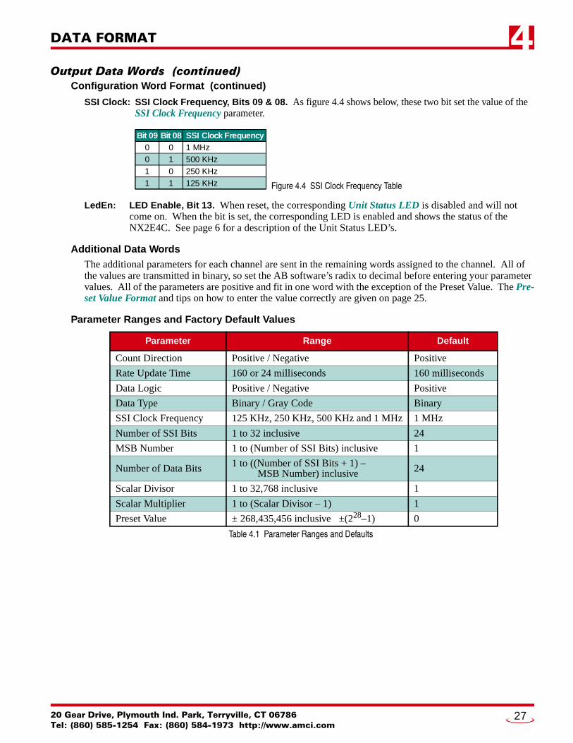
SSI Clock: SSI Clock Frequency, Bits 09 & 08. As figure 4.4 shows below, these two bit set the value of the SSI Clock Frequency parameter.
Figure 4.4 SSI Clock Frequency Table
LedEn: LED Enable, Bit 13. When reset, the corresponding Unit Status LED is disabled and will not come on. When the bit is set, the corresponding LED is enabled and shows the status of the NX2E4C. See page 6 for a description of the Unit Status LED’s.
Additional Data WordsThe additional parameters for each channel are sent in the remaining words assigned to the channel. All of the values are transmitted in binary, so set the AB software’s radix to decimal before entering your parameter values. All of the parameters are positive and fit in one word with the exception of the Preset Value. The Pre-set Value Format and tips on how to enter the value correctly are given on page 25.
Parameter Ranges and Factory Default Values
Table 4.1 Parameter Ranges and Defaults
Parameter Range Default
Count Direction Positive / Negative Positive
Rate Update Time 160 or 24 milliseconds 160 milliseconds
Data Logic Positive / Negative Positive
Data Type Binary / Gray Code Binary
SSI Clock Frequency 125 KHz, 250 KHz, 500 KHz and 1 MHz 1 MHz
Number of SSI Bits 1 to 32 inclusive 24
MSB Number 1 to (Number of SSI Bits) inclusive 1
Number of Data Bits 1 to ((Number of SSI Bits + 1) – MSB Number) inclusive 24
Scalar Divisor 1 to 32,768 inclusive 1
Scalar Multiplier 1 to (Scalar Divisor – 1) 1
Preset Value ± 268,435,456 inclusive ±(228–1) 0
Bit 09 Bit 08 SSI Clock Frequency0 0 1 MHz0 1 500 KHz1 0 250 KHz1 1 125 KHz
20 Gear Drive, Plymouth Ind. Park, Terryville, CT 06786Tel: (860) 585-1254 Fax: (860) 584-1973 http://www.amci.com
27

DATA FORMAT4
ControlLogix Input Data FormatTable 4.2 shows the format of the input data words transferred from a NX2E4C to a ControlLogix mas-ter. Note that the data format in a ControlLogix sys-tem is different than in a PLC-5 system, which is shown in table 4.3 on the next page. In a Control-Logix system, the data stream is padded with two leading data words of zero. Consequently, a transfer to a ControlLogix master requires that you set the number of input data to thirty and the data is shifted down by two words when compared to that of a PLC-5 system.
When you configure the network as described in the Adding a NX2E4C to a ControlLogix System section of chapter 3 starting on page 21, you can set the number of data words to only those you need for your applica-tion. For example, if you are using only one transducer, you can set the number of input data words to nine. If you are using two, set the number of input words to sixteen.
Multi-Word FormatLike the Preset Value in the programming data, the Data Value and Rate of Change can exceed ±32,767. Therefore, they are transmitted in two words. The lower of two words contains the bottom four digits of the value and the upper of the two words contains the remaining digits. The Rate of Change value is always positive, but the Data Value can be negative, so it is transmitted in sign-magnitude format. Bit 10 of the channel’s Status Word is used as the sign bit. When the Data Value is negative, its positive magni-tude is placed in the Data Value words and bit 10 of the Status Word is set.
Table 4.2 ControlLogix Input Data Format
Word # Data
0 0000h
1 0000h
2 CH1: Status Word
3 CH1: Upper 5 digits of Data Value
4 CH1: Lower 4 digits of Data Value
5 CH1: Upper 5 digits of Rate of Change
6 CH1: Lower 4 digits of Rate of Change
7 CH1: Upper 16 bits of SSI Data
8 CH1: Lower 16 bits of SSI Data
9 CH2: Status Word
10 CH2: Upper 5 digits of Data Value
11 CH2: Lower 4 digits of Data Value
12 CH2: Upper 5 digits of Rate of Change
13 CH2: Lower 4 digits of Rate of Change
14 CH2: Upper 16 bits of SSI Data
15 CH2: Lower 16 bits of SSI Data
16 CH3: Status Word
17 CH3: Upper 5 digits of Data Value
18 CH3: Lower 4 digits of Data Value
19 CH3: Upper 5 digits of Rate of Change
20 CH3: Lower 4 digits of Rate of Change
21 CH3: Upper 16 bits of SSI Data
22 CH3: Lower 16 bits of SSI Data
23 CH4: Status Word
24 CH4: Upper 5 digits of Data Value
25 CH4: Lower 4 digits of Data Value
26 CH4: Upper 5 digits of Rate of Change
27 CH4: Lower 4 digits of Rate of Change
28 CH4: Upper 16 bits of SSI Data
29 CH4: Lower 16 bits of SSI Data
ADVANCED MICRO CONTROLS INC.28

DATA FORMAT 4
PLC-5 Input Data FormatTable 4.3 shows the format of the input data words transferred from a NX2E4C to a PLC-5 master. Note that the data format in these systems is differ-ent than the data format in a ControlLogix system, which is shown in figure 4.2 on the previous page. In a ControlLogix system, the data stream is pad-ded with two leading data words of zero. Conse-quently, a transfer to a ControlLogix master requires that you set the number of input data to thirty and the data is shifted down by two words when compared to that of a PLC-5 system.
When you configure the network as described in the Adding a NX2E4C to a PLC-5 System section of chap-ter 3 starting on page 23, you can set the number of data words to only those you need for your applica-tion. For example, if you are using only one transducer, you can set the number of input data words to seven. If you are using two, set the number of input words to fourteen.
Multi-Word FormatLike the Preset Value in the programming data, the Data Value and Rate of Change can exceed ±32,767. Therefore, they are transmitted in two words. The lower of two words contains the bot-tom four digits of the value and the upper of the two words contains the remaining digits. The Rate of Change value is always positive, but the Data Value can be negative so it is transmitted in sign-magni-tude format. Bit 10 of the channel’s Status Word is used as the sign bit. When the Data Value is nega-tive, its positive magnitude is placed in the Data Value words and bit 10 of the Status Word is set.
Coverting Data Value and Rate of Change to Floating Point
If your processor supports floating point numbers, you can convert the Data Value or Rate of Change information with the following steps.
1) Floating Point Number = (Upper Word * 10,000 + Lower Word)2) If the Data Value sign bit = 1, then Floating Point Number = Floating Point Number * -1
Table 4.3 PLC-5 Input Data Format
Word # Data
0 CH1: Status Word
1 CH1: Upper 5 digits of Data Value
2 CH1: Lower 4 digits of Data Value
3 CH1: Upper 5 digits of Rate of Change
4 CH1: Lower 4 digits of Rate of Change
5 CH1: Upper 16 bits of SSI Data
6 CH1: Lower 16 bits of SSI Data
7 CH2: Status Word
8 CH2: Upper 5 digits of Data Value
9 CH2: Lower 4 digits of Data Value
10 CH2: Upper 5 digits of Rate of Change
11 CH2: Lower 4 digits of Rate of Change
12 CH2: Upper 16 bits of SSI Data
13 CH2: Lower 16 bits of SSI Data
14 CH3: Status Word
15 CH3: Upper 5 digits of Data Value
16 CH3: Lower 4 digits of Data Value
17 CH3: Upper 5 digits of Rate of Change
18 CH3: Lower 4 digits of Rate of Change
19 CH3: Upper 16 bits of SSI Data
20 CH3: Lower 16 bits of SSI Data
21 CH4: Status Word
22 CH4: Upper 5 digits of Data Value
23 CH4: Lower 4 digits of Data Value
24 CH4: Upper 5 digits of Rate of Change
25 CH4: Lower 4 digits of Rate of Change
26 CH4: Upper 16 bits of SSI Data
27 CH4: Lower 16 bits of SSI Data
20 Gear Drive, Plymouth Ind. Park, Terryville, CT 06786Tel: (860) 585-1254 Fax: (860) 584-1973 http://www.amci.com
29

DATA FORMAT4
Status Word FormatThe input data of each channel has a Status Word that contains programming error bits, status bits for the transducer, and, in the case of the first channel, the Acknowledge Bit that is used during a Programming Cycle. Figure 4.5 shows the format of a Status Word.
Figure 4.5 Status Word Format
Programming Error BitsProgramming error bits, (00-07), are not set until a Programming Cycle is initiated and remain set until the next Programming Cycle.
CfgErr: Configuration Error, Bit 00. Set if any reserved bits in the Configuration Word are set.
SSIErr: SSI Setup Parameter Error, Bit 01. This bit is set to signal one of the following conditions:1) The Number of SSI Bits specified for the channel is not in the range of 1 to 32.
2) The MSB Number specified for the channel is zero, or greater than the Number of SSI Bits.3) The Number of Data Bits specified for the channel is zero, greater than twenty-eight, or
greater that the Number of SSI Bits.4) The sum of (“MSB Number” + “Number of Data Bits”) exceeds the sum of (“Number of
SSI Bits” + 1)
DivErr: Scalar Divisor Error, Bit 02. This bit is set if you attempt to program the Scalar Divisor to a value outside its range of 1 to 32,767 inclusive.
MulErr: Scalar Multiplier Error, Bit 03. This bit is set if you attempt to program the Scalar Multiplier to a value outside its range of 1 to 32,767 inclusive, or greater than the Scalar Divisor.
PVErr: Preset Value Error, Bit 04. This bit is set if the Preset Value is outside of its range of ±268,435,455. A common cause of this error is incorrectly splitting the Preset Value into its two words. See Preset Value Format on page 25 for information on the correct format.
CmdErr: Command Error, Bit 06. Set if any reserved bits in the Control Word are set or if you attempt to program channels and apply preset values with one Programming Cycle.
MsgIgn: Message Ignored, Bit 07. If an error occurs when programming a parameter, the only way to clear the error is by setting the Clear Errors bit in the Control Word, or by re-programming the parameter to an acceptable value. This bit is set if neither of these actions occurred in the Programming Cycle immediately after the one that caused the error.
15 14 13 12 10 09 08 07 06 05 04 03 02 01 0011
Status Word FormatFour Status Words total, One for each channel
Cfg
Err
Cm
dErr
Msg
Ign
0
Vel@
0
MD
ir
SSIE
rr
Div
Err
Mul
Err
PVEr
r
DVS
ign
RO
vFlo
Mod
Err
ACK
00
RESERVED:Bit will equal zero.
CH 1 ONLY:This bit will equal zero in thestatus words of channels 2-4.
ADVANCED MICRO CONTROLS INC.30

DATA FORMAT 4
Status Word Format (continued)Transducer & Unit Status BitsUnlike the Programming Error bits, (00-07), the Transducer and Unit Status bits are always valid. They are updated continuously.
Vel@0: Velocity at Zero, Bit 08. This bit is reset when the transducer is in motion and set when there is no motion during a Rate Update Time. This time is either 24 or 160 milliseconds.
MDir: Motion Direction, Bit 09. This bit is reset when the position value is increasing and set when the position value is decreasing. This bit remains in its last state when there is no motion.
DVSign: Data Value Sign, Bit 10. This bit is reset if the Data Value for the channel is positive and set if it is negative. The absolute value of the Data Value is always placed in its two input words.
ROvFlo: Rate Overflow, Bit 12. Set when the Rate of Change value is greater than 232 counts per second. When this occurs, the last valid Rate of Change value is sent to the processor.
NxFlt: NX2E4C Fault, Bit 14. This bit is set when the NX2E4C discovers a problem with its hardware. If this bit is set, initiate a Programming Cycle with the Clear Errors bit set in the Control Word. If the error remains, cycle power to the unit. If the error is still not cleared, contact AMCI for assis-tance. See the inside front cover for contact information. If the error does clear, then you will probably have to reprogram the unit because all parameters are set back to their factory default val-ues.
ACK: Acknowledge Bit, Bit 0/15. This bit only exists in the Status word of channel one. In the Status Words for channels 2, 3, and 4, this bit equals zero. This bit is set by the NX2E4C to acknowledge a Programming Cycle from the ControlNet master. Programming Error Bits in the Status words are valid while this bit is set. The Transducer & Unit Status Bits are always valid. The unit resets the Acknowledge bit after the ControlNet master resets the Transmit Bit.
20 Gear Drive, Plymouth Ind. Park, Terryville, CT 06786Tel: (860) 585-1254 Fax: (860) 584-1973 http://www.amci.com
31

DATA FORMAT4
NotesADVANCED MICRO CONTROLS INC.32

20 Gear Drive, Plymouth IndTel: (860) 585-1254 Fax: (8
CHAPTER 5
SAMPLE PROGRAMLadder Logic FormatThe ladder logic on the following pages is written for the PLC-5, but can easily be converted to the Control-Logix platform because the instructions are the same. The way the data is addressed is the only thing that changes.
PLC-5 Data FormatN9:0-27: Integer data file words assigned to the NX2E4C input words. N9:0/15 is the Acknowledge Bit.
N10:0-32: Integer data file words assigned to the NX2E4C output words. N10:0/15 is the Transmit Bit.
N14:0-33: This thirty-four word file holds the two programming block that are written to the NX2E4C. N14:0-32 holds the first block which programs the four channels. N14:34 holds the command that preset channels one and three to the Preset Values programmed with the first block.
C5:0 Up Counter used to control which programming block is transmitted to the unit.
ControlLogix Data FormatN9: The N9 file references are replaced with the data tag you defined when configuring the RSLogix 5000
software. For example, if you named the NX2E4C “SSINexusNode”, then the input data would be at SSINexusNode:I.Data[0-29]. See RSLogix 5000 Setup starting on page 21 for additional information on the data format. Remember that ControlLogix requires thirty input words, not twenty-eight. Because the first two words are reserved, the Acknowledge Bit will be at SSINexusNode:I.Data[2].15.
N10: Like the N9 references, the N10 references are replaced with the data tag you defined when configur-ing the RSLogix 5000 software. For example, if you named the NX2E4C “SSINexusNode”, then the output data would be at SSINexusNode:O.Data[0-32]. See RSLogix 5000 Setup starting on page 21 for additional data format information. The Transmit Bit will be at SSINexusNode:O.Data[0].15.
N14: The N14 file references need to be replaced with arrays that you define to hold the data. For more information on defining arrays, refer to A-B documentation or help files.
C5:0 The counter is replaced with the ControlLogix counter structure.
. Park, Terryville, CT 0678660) 584-1973 http://www.amci.com
33
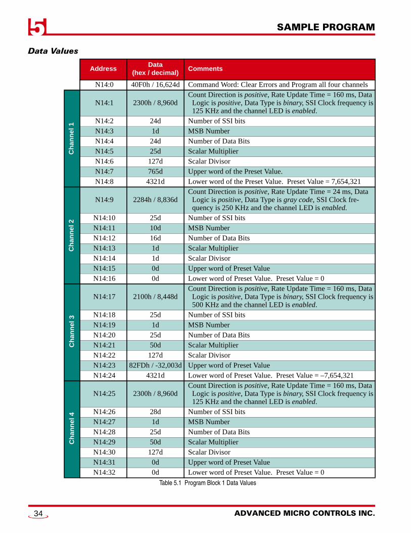
SAMPLE PROGRAM5
Data ValuesTable 5.1 Program Block 1 Data Values
AddressData
(hex / decimal)Comments
N14:0 40F0h / 16,624d Command Word: Clear Errors and Program all four channels
Ch
ann
el 1
N14:1 2300h / 8,960dCount Direction is positive, Rate Update Time = 160 ms, Data
Logic is positive, Data Type is binary, SSI Clock frequency is 125 KHz and the channel LED is enabled.
N14:2 24d Number of SSI bitsN14:3 1d MSB NumberN14:4 24d Number of Data BitsN14:5 25d Scalar MultiplierN14:6 127d Scalar DivisorN14:7 765d Upper word of the Preset Value. N14:8 4321d Lower word of the Preset Value. Preset Value = 7,654,321
Ch
ann
el 2
N14:9 2284h / 8,836dCount Direction is positive, Rate Update Time = 24 ms, Data
Logic is positive, Data Type is gray code, SSI Clock fre-quency is 250 KHz and the channel LED is enabled.
N14:10 25d Number of SSI bitsN14:11 10d MSB NumberN14:12 16d Number of Data BitsN14:13 1d Scalar MultiplierN14:14 1d Scalar DivisorN14:15 0d Upper word of Preset ValueN14:16 0d Lower word of Preset Value. Preset Value = 0
Ch
ann
el 3
N14:17 2100h / 8,448dCount Direction is positive, Rate Update Time = 160 ms, Data
Logic is positive, Data Type is binary, SSI Clock frequency is 500 KHz and the channel LED is enabled.
N14:18 25d Number of SSI bitsN14:19 1d MSB NumberN14:20 25d Number of Data BitsN14:21 50d Scalar MultiplierN14:22 127d Scalar DivisorN14:23 82FDh / -32,003d Upper word of Preset ValueN14:24 4321d Lower word of Preset Value. Preset Value = –7,654,321
Ch
ann
el 4
N14:25 2300h / 8,960dCount Direction is positive, Rate Update Time = 160 ms, Data
Logic is positive, Data Type is binary, SSI Clock frequency is 125 KHz and the channel LED is enabled.
N14:26 28d Number of SSI bitsN14:27 1d MSB NumberN14:28 25d Number of Data BitsN14:29 50d Scalar MultiplierN14:30 127d Scalar DivisorN14:31 0d Upper word of Preset ValueN14:32 0d Lower word of Preset Value. Preset Value = 0
ADVANCED MICRO CONTROLS INC.34
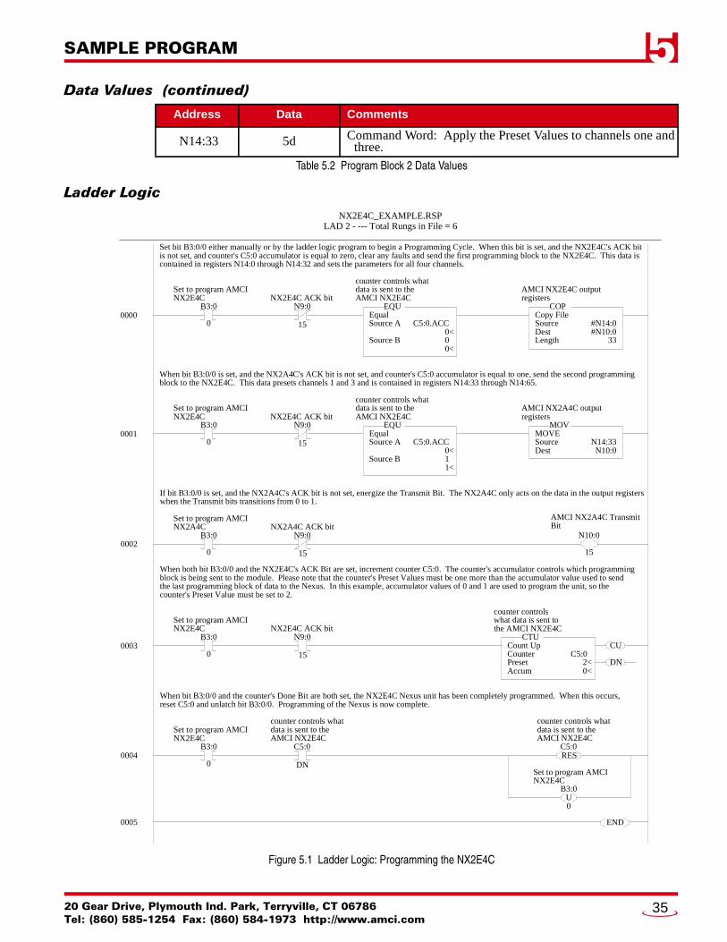
SAMPLE PROGRAM 5
Data Values (continued)Table 5.2 Program Block 2 Data Values
Ladder Logic
Figure 5.1 Ladder Logic: Programming the NX2E4C
Address Data Comments
N14:33 5d Command Word: Apply the Preset Values to channels one and three.
0000
NX2E4C_EXAMPLE.RSPLAD 2 - --- Total Rungs in File = 6
AMCI NX2E4C outputregisters
Copy FileSourceDestLength
COP
#N14:0#N10:0
33
B3:0
0
Set to program AMCINX2E4C
N9:0
15
NX2E4C ACK bit
Set bit B3:0/0 either manually or by the ladder logic program to begin a Programming Cycle. When this bit is set, and the NX2E4C's ACK bitis not set, and counter's C5:0 accumulator is equal to zero, clear any faults and send the first programming block to the NX2E4C. This data iscontained in registers N14:0 through N14:32 and sets the parameters for all four channels.
0002
AMCI NX2A4C TransmitBit
B3:0
0
Set to program AMCINX2A4C
If bit B3:0/0 is set, and the NX2A4C's ACK bit is not set, energize the Transmit Bit. The NX2A4C only acts on the data in the output registerswhen the Transmit bits transitions from 0 to 1.
N10:0
15
counter controls whatdata is sent to theAMCI NX2E4C
EqualSource A
Source B
EQU
C5:0.ACC<0<0<0<
0001
AMCI NX2A4C outputregisters
MOVESourceDest
MOV
N14:33N10:0
B3:0
0
Set to program AMCINX2E4C
N9:0
15
NX2E4C ACK bit
When bit B3:0/0 is set, and the NX2A4C's ACK bit is not set, and counter's C5:0 accumulator is equal to one, send the second programmingblock to the NX2E4C. This data presets channels 1 and 3 and is contained in registers N14:33 through N14:65.
counter controls whatdata is sent to theAMCI NX2E4C
EqualSource A
Source B
EQU
C5:0.ACC<0<1<1<
N9:0
15
NX2A4C ACK bit
0003
counter controlswhat data is sent tothe AMCI NX2E4C
Count UpCounterPresetAccum
CTU
C5:0<2<0<
B3:0
0
Set to program AMCINX2E4C
N9:0
15
NX2E4C ACK bit
When both bit B3:0/0 and the NX2E4C's ACK Bit are set, increment counter C5:0. The counter's accumulator controls which programmingblock is being sent to the module. Please note that the counter's Preset Values must be one more than the accumulator value used to sendthe last programming block of data to the Nexus. In this example, accumulator values of 0 and 1 are used to program the unit, so thecounter's Preset Value must be set to 2.
0004B3:0
0
Set to program AMCINX2E4C
C5:0
DN
When bit B3:0/0 and the counter's Done Bit are both set, the NX2E4C Nexus unit has been completely programmed. When this occurs,reset C5:0 and unlatch bit B3:0/0. Programming of the Nexus is now complete.
counter controls whatdata is sent to theAMCI NX2E4C
CU
DN
C5:0
counter controls whatdata is sent to theAMCI NX2E4C
RES
B3:0
0
Set to program AMCINX2E4C
U
0005 END
20 Gear Drive, Plymouth Ind. Park, Terryville, CT 06786Tel: (860) 585-1254 Fax: (860) 584-1973 http://www.amci.com
35

SAMPLE PROGRAM5
NotesADVANCED MICRO CONTROLS INC.36
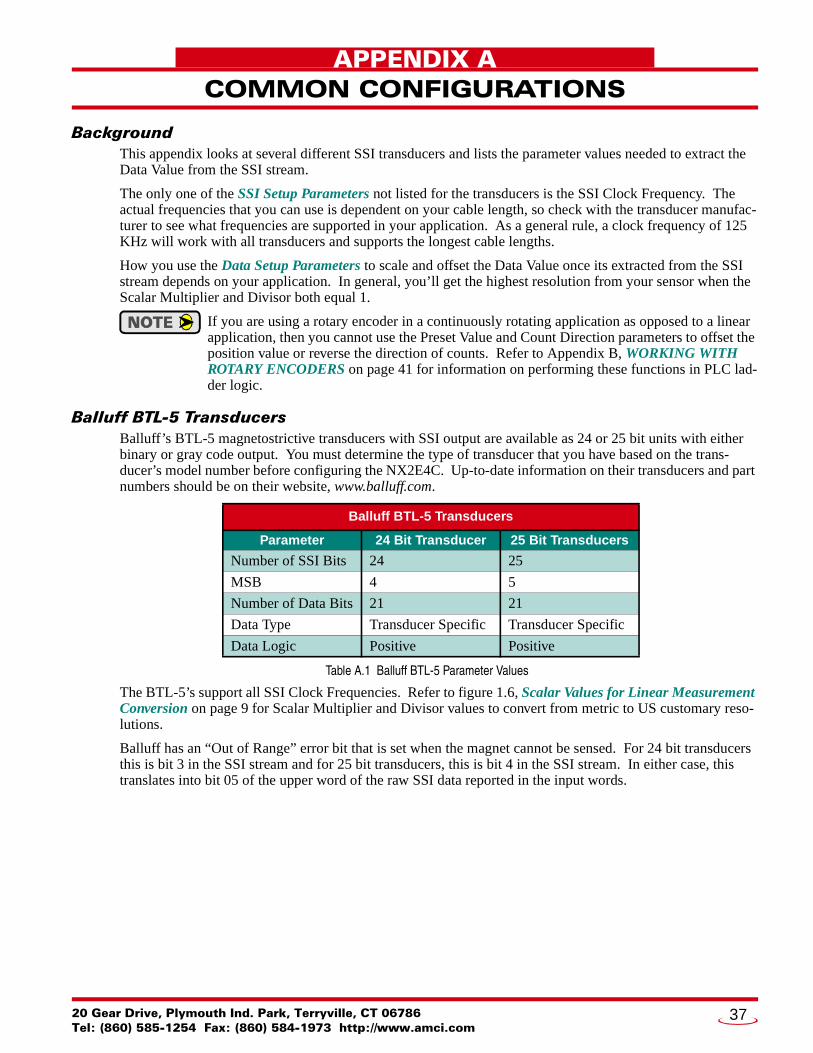
20 Gear Drive, Plymouth IndTel: (860) 585-1254 Fax: (8
APPENDIX A
COMMON CONFIGURATIONSBackgroundThis appendix looks at several different SSI transducers and lists the parameter values needed to extract the Data Value from the SSI stream.
The only one of the SSI Setup Parameters not listed for the transducers is the SSI Clock Frequency. The actual frequencies that you can use is dependent on your cable length, so check with the transducer manufac-turer to see what frequencies are supported in your application. As a general rule, a clock frequency of 125 KHz will work with all transducers and supports the longest cable lengths.
How you use the Data Setup Parameters to scale and offset the Data Value once its extracted from the SSI stream depends on your application. In general, you’ll get the highest resolution from your sensor when the Scalar Multiplier and Divisor both equal 1.
If you are using a rotary encoder in a continuously rotating application as opposed to a linear application, then you cannot use the Preset Value and Count Direction parameters to offset the position value or reverse the direction of counts. Refer to Appendix B, WORKING WITH ROTARY ENCODERS on page 41 for information on performing these functions in PLC lad-der logic.
Balluff BTL-5 TransducersBalluff’s BTL-5 magnetostrictive transducers with SSI output are available as 24 or 25 bit units with either binary or gray code output. You must determine the type of transducer that you have based on the trans-ducer’s model number before configuring the NX2E4C. Up-to-date information on their transducers and part numbers should be on their website, www.balluff.com.
Table A.1 Balluff BTL-5 Parameter Values
The BTL-5’s support all SSI Clock Frequencies. Refer to figure 1.6, Scalar Values for Linear Measurement Conversion on page 9 for Scalar Multiplier and Divisor values to convert from metric to US customary reso-lutions.
Balluff has an “Out of Range” error bit that is set when the magnet cannot be sensed. For 24 bit transducers this is bit 3 in the SSI stream and for 25 bit transducers, this is bit 4 in the SSI stream. In either case, this translates into bit 05 of the upper word of the raw SSI data reported in the input words.
Balluff BTL-5 Transducers
Parameter 24 Bit Transducer 25 Bit Transducers
Number of SSI Bits 24 25
MSB 4 5
Number of Data Bits 21 21
Data Type Transducer Specific Transducer Specific
Data Logic Positive Positive
. Park, Terryville, CT 0678660) 584-1973 http://www.amci.com
37
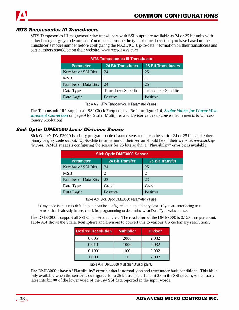
COMMON CONFIGURATIONSA
MTS Temposonics III TransducersMTS Temposonics III magnetostrictive transducers with SSI output are available as 24 or 25 bit units with either binary or gray code output. You must determine the type of transducer that you have based on the transducer’s model number before configuring the NX2E4C. Up-to-date information on their transducers and part numbers should be on their website, www.mtssensors.com.
Table A.2 MTS Temposonics III Parameter Values
The Temposonic III’s support all SSI Clock Frequencies. Refer to figure 1.6, Scalar Values for Linear Mea-surement Conversion on page 9 for Scalar Multiplier and Divisor values to convert from metric to US cus-tomary resolutions.
Sick Optic DME3000 Laser Distance SensorSick Optic’s DME3000 is a fully programmable distance sensor that can be set for 24 or 25 bits and either binary or gray code output. Up-to-date information on their sensor should be on their website, www.sickop-tic.com. AMCI suggests configuring the sensor for 25 bits so that a “Plausibility” error bit is available.
Table A.3 Sick Optic DME3000 Parameter Values
†Gray code is the units default, but it can be configured to output binary data. If you are interfacing to a sensor that is already in use, check its programming to determine what Data Type value to use.
The DME3000’s support all SSI Clock Frequencies. The resolution of the DME3000 is 0.125 mm per count. Table A.4 shows the Scalar Multipliers and Divisors to convert this to various US customary resolutions.
Table A.4 DME3000 Multiplier/Divisor pairs.
The DME3000’s have a “Plausibility” error bit that is normally on and reset under fault conditions. This bit is only available when the sensor is configured for a 25 bit transfer. It is bit 25 in the SSI stream, which trans-lates into bit 00 of the lower word of the raw SSI data reported in the input words.
MTS Temposonics III Transducers
Parameter 24 Bit Transducer 25 Bit Transducers
Number of SSI Bits 24 25
MSB 1 1
Number of Data Bits 24 25
Data Type Transducer Specific Transducer Specific
Data Logic Positive Positive
Sick Optic DME3000 Sensor
Parameter 24 Bit Transfer 25 Bit Transfer
Number of SSI Bits 24 25
MSB 2 2
Number of Data Bits 23 23
Data Type Gray† Gray†
Data Logic Positive Positive
Desired Resolution Multiplier Divisor
0.005" 2000 2,032
0.010" 1000 2,032
0.100" 100 2,032
1.000" 10 2,032
ADVANCED MICRO CONTROLS INC.38
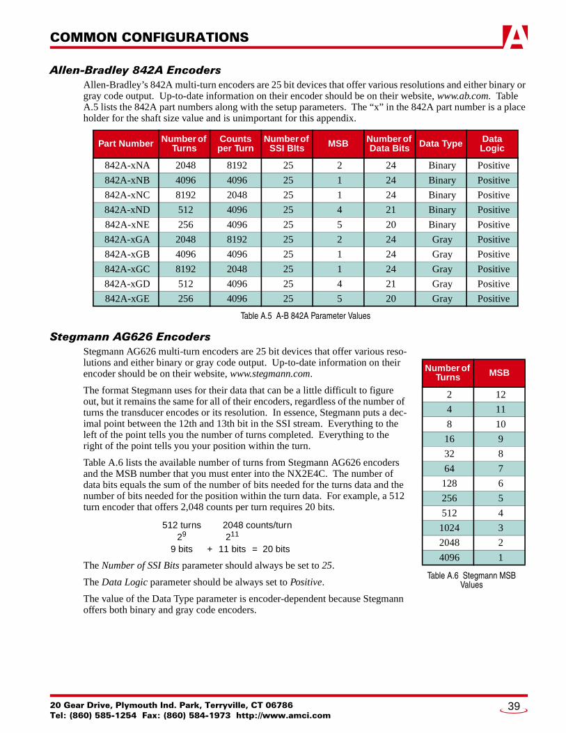
COMMON CONFIGURATIONS A
Allen-Bradley 842A EncodersAllen-Bradley’s 842A multi-turn encoders are 25 bit devices that offer various resolutions and either binary or gray code output. Up-to-date information on their encoder should be on their website, www.ab.com. Table A.5 lists the 842A part numbers along with the setup parameters. The “x” in the 842A part number is a place holder for the shaft size value and is unimportant for this appendix.
Table A.5 A-B 842A Parameter Values
Stegmann AG626 EncodersStegmann AG626 multi-turn encoders are 25 bit devices that offer various reso-lutions and either binary or gray code output. Up-to-date information on their encoder should be on their website, www.stegmann.com.
The format Stegmann uses for their data that can be a little difficult to figure out, but it remains the same for all of their encoders, regardless of the number of turns the transducer encodes or its resolution. In essence, Stegmann puts a dec-imal point between the 12th and 13th bit in the SSI stream. Everything to the left of the point tells you the number of turns completed. Everything to the right of the point tells you your position within the turn.
Table A.6 lists the available number of turns from Stegmann AG626 encoders and the MSB number that you must enter into the NX2E4C. The number of data bits equals the sum of the number of bits needed for the turns data and the number of bits needed for the position within the turn data. For example, a 512 turn encoder that offers 2,048 counts per turn requires 20 bits.
The Number of SSI Bits parameter should always be set to 25.
The Data Logic parameter should be always set to Positive.
The value of the Data Type parameter is encoder-dependent because Stegmann offers both binary and gray code encoders.
Part Number Number of Turns
Counts per Turn
Number of SSI BIts MSB Number of
Data Bits Data Type Data Logic
842A-xNA 2048 8192 25 2 24 Binary Positive
842A-xNB 4096 4096 25 1 24 Binary Positive
842A-xNC 8192 2048 25 1 24 Binary Positive
842A-xND 512 4096 25 4 21 Binary Positive
842A-xNE 256 4096 25 5 20 Binary Positive
842A-xGA 2048 8192 25 2 24 Gray Positive
842A-xGB 4096 4096 25 1 24 Gray Positive
842A-xGC 8192 2048 25 1 24 Gray Positive
842A-xGD 512 4096 25 4 21 Gray Positive
842A-xGE 256 4096 25 5 20 Gray Positive
512 turns 2048 counts/turn29 211
9 bits + 11 bits = 20 bits
Table A.6 Stegmann MSBValues
Number of Turns MSB
2 12
4 11
8 10
16 9
32 8
64 7
128 6
256 5
512 4
1024 3
2048 2
4096 1
20 Gear Drive, Plymouth Ind. Park, Terryville, CT 06786Tel: (860) 585-1254 Fax: (860) 584-1973 http://www.amci.com
39
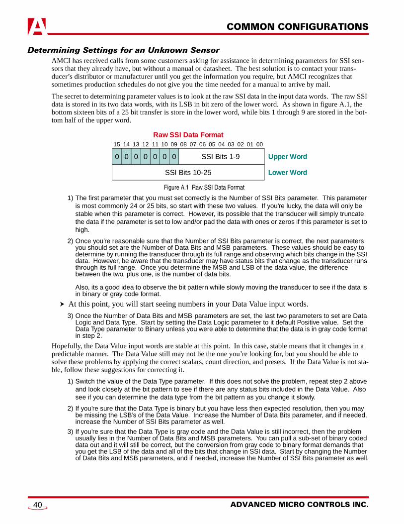
COMMON CONFIGURATIONSA
Determining Settings for an Unknown SensorAMCI has received calls from some customers asking for assistance in determining parameters for SSI sen-sors that they already have, but without a manual or datasheet. The best solution is to contact your trans-ducer’s distributor or manufacturer until you get the information you require, but AMCI recognizes that sometimes production schedules do not give you the time needed for a manual to arrive by mail.
The secret to determining parameter values is to look at the raw SSI data in the input data words. The raw SSI data is stored in its two data words, with its LSB in bit zero of the lower word. As shown in figure A.1, the bottom sixteen bits of a 25 bit transfer is store in the lower word, while bits 1 through 9 are stored in the bot-tom half of the upper word.
Figure A.1 Raw SSI Data Format
1) The first parameter that you must set correctly is the Number of SSI Bits parameter. This parameter is most commonly 24 or 25 bits, so start with these two values. If you’re lucky, the data will only be stable when this parameter is correct. However, its possible that the transducer will simply truncate the data if the parameter is set to low and/or pad the data with ones or zeros if this parameter is set to high.
2) Once you’re reasonable sure that the Number of SSI Bits parameter is correct, the next parameters you should set are the Number of Data Bits and MSB parameters. These values should be easy to determine by running the transducer through its full range and observing which bits change in the SSI data. However, be aware that the transducer may have status bits that change as the transducer runs through its full range. Once you determine the MSB and LSB of the data value, the difference between the two, plus one, is the number of data bits.
Also, its a good idea to observe the bit pattern while slowly moving the transducer to see if the data is in binary or gray code format.
At this point, you will start seeing numbers in your Data Value input words.
3) Once the Number of Data Bits and MSB parameters are set, the last two parameters to set are Data Logic and Data Type. Start by setting the Data Logic parameter to it default Positive value. Set the Data Type parameter to Binary unless you were able to determine that the data is in gray code format in step 2.
Hopefully, the Data Value input words are stable at this point. In this case, stable means that it changes in a predictable manner. The Data Value still may not be the one you’re looking for, but you should be able to solve these problems by applying the correct scalars, count direction, and presets. If the Data Value is not sta-ble, follow these suggestions for correcting it.
1) Switch the value of the Data Type parameter. If this does not solve the problem, repeat step 2 above and look closely at the bit pattern to see if there are any status bits included in the Data Value. Also see if you can determine the data type from the bit pattern as you change it slowly.
2) If you’re sure that the Data Type is binary but you have less then expected resolution, then you may be missing the LSB’s of the Data Value. Increase the Number of Data Bits parameter, and if needed, increase the Number of SSI Bits parameter as well.
3) If you’re sure that the Data Type is gray code and the Data Value is still incorrect, then the problem usually lies in the Number of Data Bits and MSB parameters. You can pull a sub-set of binary coded data out and it will still be correct, but the conversion from gray code to binary format demands that you get the LSB of the data and all of the bits that change in SSI data. Start by changing the Number of Data Bits and MSB parameters, and if needed, increase the Number of SSI Bits parameter as well.
15 14 13 12 10 09 08 07 06 05 04 03 02 01 0011
0
Raw SSI Data Format
00 0 0 0 0 SSI Bits 1-9
SSI Bits 10-25
Upper Word
Lower Word
ADVANCED MICRO CONTROLS INC.40
20 Gear Drive, Plymouth IndTel: (860) 585-1254 Fax: (8
APPENDIX B
WORKING WITH ROTARY ENCODERSDefinition of a Rotary EncoderA rotary encoder is any device that can return to a starting value by traveling in one direction. Rotary encod-ers also exhibit a “roll over” condition when the output changes from its maximum value to its minimum or it minimum to its maximum. Take a Stegmann AG626 ten bit encoder for example. If you start at the zero posi-tion and continuously rotate the shaft clockwise, eventually you will return to the zero value. The roll over occurs when the value changes from 1,023 to zero or from zero to 1,023.
In contrast, a linear encoder is any device that can only return to a starting position by reversing the direction of motion. Take a MTS Temposonics III transducer for example. The transducer outputs a specific position value when the magnet is close to the transducers head. As the magnet travels away from the head of the transducer, the position value will change, and the only way to get back to the starting position is by reversing the magnet’s motion.
Note that a linear encoder can behave as a rotary encoder if the Data Value is not extracted from the SSI stream correctly. For example, assume an eight bit linear encoder whose output ranges from 0 to 255. If you configure the Data Value to read only the bottom seven bits, its range will be zero to 127. As long as the value from the transducer is 127 or less, the system will be correct. As soon as the position becomes 128 however, the Data Value will return to zero.
Definition of Full Scale CountIn order to reverse the count direction or offset the value of a rotary encoder, you need to know the number of counts the encoder produces. AMCI calls this value the encoder’s Full Scale Count. For example, a 12 bit single-turn encoder has a Full Scale Count of 4,096. If the resolution of the encoder is changed to 0.1º with a Scalar Multiplier/Divisor of 3600/4096, then the Full Scale Count becomes 3600.
Reversing The Count DirectionReversing the count direction of a rotary encoder is a two step process. First, if the Data Value is zero, do nothing. If the Data Value is non-zero, then the Data Value becomes (Full Scale Count - Data Value).
Memory NeededThe ladder logic requires two floating point registers. The first contains the Data Value from the NX2E4C after its converted to a floating point value. The second contains the Full Scale Count. This value is constant, but must be stored in a register because it cannot be entered into the instruction as a literal.
F8:0: Current Position. This is the position data read from the NX2E4C after it is converted to float-ing point. It also contains the reversed count when the ladder logic is complete.
F8:1: Full Scale Count. This register holds the Full Scale Count value.
Floating point registers are used in the example because the Full Scale Count can be as high as 228. If your Full Scale Count is 32,767 or less, then you can use signed integer registers instead of floating point. The instructions remain the same, but the PLC’s work on integer reg-isters much faster than they work on floating point registers. Using integer registers also allow you to eliminate the Full Scale Count register because the value can be entered into the instruc-tions as a literal.
The following ladder logic example program is written for the Allen-Bradley PLC-5 processors. However, the code can easily be converted to the ControlLogix platform.
. Park, Terryville, CT 0678660) 584-1973 http://www.amci.com
41

WORKING WITH ROTARY ENCODERSB
Reversing The Count Direction (continued)Ladder Logic
Figure B.1 Ladder Logic: Reversing Count Direction
Offsetting the Data ValueOffsetting the Data Value involves calculating the offset needed to bring the Data Value to a known value when an internal “Preset Data Value” bit is set and then applying the offset to the Data Value every scan.
If you are reversing the count direction and offsetting the data value, then reverse the count direction first. The two examples in this appendix were written so that they could be combined. Simply remove rung 0000 from this example and add the rest to the end of the count direction example and the two sections will work together.
The following ladder logic example program is written for the Allen-Bradley PLC-5 processors. However, the code can easily be converted to the ControlLogix platform.
NX2E4C_REVCD.RSP
LAD 2 - --- Total Rungs in File = 3
0001
Combined Channel 1 Data Value
SUBTRACTSource A
Source B
Dest
SUB
F8:1<262144<
F8:0<138688<
F8:0<123456<
If the Data Value is zero, leave it alone. If its non-zero, subtract it from the Full Scale Count to reverse the count direction. The exampleassumes an 18 bit encoder, so the Full Scale Count is 262,144. This value is stored in F8:1.
Combined Channel 1 Data Value
NOT EQUALSource A
Source B
NEQ
F8:0<138688<
0<0<
0000
Combined Channel 1 Data Value
MultiplySource A
Source B
Dest
MUL
N9:1<13<
10000<10000<
F8:0<130000<
AddSource A
Source B
Dest
ADD
F8:0<130000<
N7:2<8688<F8:0
138688<
Combined Channel 1 Data Value
Before reversing count direction, the Data Value must be converted to floating point. The N9 address of the Data Value assumes that the inputdata from the NX2E4C is stored starting at N9:0 and that the Data Value being converted is from channel one. This conversion rung does nottake into account the position's sign bit. Rotary encoders will never output negative values.
0002 END
ADVANCED MICRO CONTROLS INC.42

WORKING WITH ROTARY ENCODERS B
Offsetting the Data Value (continued)Memory NeededThe ladder logic requires four floating point registers and two bits. The Full Scale Count and Desired Posi-tion registers contain constants, but they must be stored in registers because they cannot be entered into the instruction as literals.
F8:0: Current Position. This is the position data read from the NX2E4C after it is converted. it also stores the offset position after the ladder logic is scanned.
F8:1: Full Scale Count. This register holds the Full Scale Count value.F8:2: Desired Position. This register holds the position that you want the current position to become
when a new offset is calculated and applied. The range of this value is: 0 to (Full Scale Count -1).F8:3: Internal Offset. This is the calculated offset that is applied to the Current Position on every scan.B3:0/00: Calculate Offset. Set this bit to calculate a new Internal Offset.B3:0/01: One Shot. This bit is used in a one-shot to make sure that the Internal Offset is only calcu-
lated once if the Calculate Offset bit remains set for more than one scan.
Floating point registers are used in the example because the Full Scale Count can be as high as 228. If your Full Scale Count is 32,767 or less, then you can use signed integer registers instead of floating point. The instructions remain the same, but the PLC’s work on integer reg-isters much faster than they work on floating point registers. Using integer registers also allow you to eliminate the Full Scale Count and Desired Position registers because their values can be entered into the instructions as literals.
Ladder Logic
CONTINUED
0001
NX2E4C_OFFSET.RSP
LAD 2 - --- Total Rungs in File = 6
Internal Offset
SubtractSource A
Source B
Dest
SUB
F8:0<123456<
F8:2<18000<
F8:3<105456<
B3:0
0
Set to calculateoffset value
Internal bit B3:0/0 must be set to trigger the offset opeartion. When this bit is set, and the one-shot has not triggered, subtract the DesiredValue, stored in F8:2, from the NX2E4C's Data Value in F8:0. The result is the Internal Offset and is stored in F8:3. The ladder logicprogram must reset B3:0/0 before another Internal Offset can be calculated.
0000
Combined Channel 1 Data Value
MultiplySource A
Source B
Dest
MUL
N9:1<12<
10000<10000<
F8:0<120000<
AddSource A
Source B
Dest
ADD
F8:0<120000<
N7:2<3456<F8:0
123456<
Combined Channel 1 Data Value
Before offsetting the Data Value, it must be converted to floating point. The N9 address of the Data Value assumes that the input data fromthe NX2E4C is stored starting at N9:0 and that the Data Value being converted is from channel one. This conversion rung does nottake into account the position's sign bit. Rotary encoders will never output negative values.
B3:0
1OSR
20 Gear Drive, Plymouth Ind. Park, Terryville, CT 06786Tel: (860) 585-1254 Fax: (860) 584-1973 http://www.amci.com
43

WORKING WITH ROTARY ENCODERSB
Offsetting the Data Value (continued)Ladder Logic (continued)
Figure B.2 Ladder Logic: Offsetting a Circular Data Value
NX2E4C_OFFSET.RSP
LAD 2 - --- Total Rungs in File = 6
0005 END
0003
Offset Position Data
SubtractSource A
Source B
Dest
SUB
F8:0<123456<
F8:3<105456<
F8:4<18000<
Calculate the Offset Position by subtracting the Internal Offset value, contained in F8:3, from the NX2E4C's Data Value contained in F8:0.The Offset Position is stored in F8:4 and must be used by the ladder logic program for all compare purposes.
0004
Internal Offset
AddSource A
Source B
Dest
ADD
F8:4<18000<
F8:1<262144<
F8:4<18000<
If the Offset Position is negative, it must be modified by adding the Full Scale Count to it. The Full Scale Count is in F8:1.
Offset Position Value
Less Than (A<B)Source A
Source B
LES
F8:4<18000<
0<0<
0002
Internal Offset
AddSource A
Source B
Dest
ADD
F8:3<105456<
F8:1<262144<
F8:3<105456<
If the Internal Offset is negative, modify it by adding the Full Scale Count to it. The Full Scale Count, in F8:2, is the number of counts pro-duced by the encoder. For example, a 12 bit encoder produces 4,096 counts. This example uses an 18 bit encoder that produces 262,144 counts.
Internal Offset
Less Than (A<B)Source A
Source B
LES
F8:3<105456<
0<0<
ADVANCED MICRO CONTROLS INC.44

WORKING WITH ROTARY ENCODERS B
Notes on Rate Of Change DataThe NX2E4C calculates the Rate of Change, which is velocity in rotary application, as the change in position over the programmed update time. Whenever the rotary encoder rolls over, the NX2E4C see a very large change in position in one update time. For example, consider a 15 bit single-turn encoder that rotates at a rate of 1 count per 24 milliseconds. With the Rate Update time set at 24 milliseconds, the Velocity will read 42 counts per second (1,000ms *1count/24ms), until the encoder goes through zero. At that point, the NX2E4C sees a 32,767 count difference in 24 milliseconds and sets the velocity to (1,000ms * 32,767counts/24 ms) = 1,365,333 counts per second for one update time.
If you are using the velocity data from the NX2E4C, you should first calculate the maximum speed of your machine and write your ladder logic to ignore any velocity data from the NX2E4C that exceeds this value.
20 Gear Drive, Plymouth Ind. Park, Terryville, CT 06786Tel: (860) 585-1254 Fax: (860) 584-1973 http://www.amci.com
45

L
ADV ANC ED MIC RO CONTROLS INC.ADV ANC ED MIC RO CONTROLS INC.ADV ANC ED MIC RO CONTROLS INC.ADV ANC ED MIC RO CONTROLS INC.20 GEAR DRIVE, TERRYVILLE, CT 06786 T: (860) 585-1254 F: (860) 584-1973
www.amci.com
EADERS IN ADVANCED CONTROL PRODUCTS