Embed Size (px)
Citation preview

DABOTEK Birkedam 10 C - DK 6000 Kolding – Denmark - Tlf.: +45 7550 5666 - Fax.:+45 7550 4795
[email protected] ; www.dabotek.eu
DABOTEK
DT1200i
P/N 101201
1200 Amp Drawn Arc Stud Welder
OPERATING MANUAL REVISED MARCH 2009
Declaration of Conformity
Manufacturer for DABOTEK Name: ARCON Welding Equipment, LLC
Manufacturer’s Address: 2203 Northwood Drive, Building 10 Salisbury, Maryland 21801 USA
Declares that the product: Product Name: DT1200i
Model Number 101200-xxx 101201-xxx
Conforms to the following standards: Underwriters Laboratories Standard UL551
Safety: EN 60974-1 2002 Degree of Enclosure Protection IP 24 in accordance with ISO 60529 This product is in conformity with the requirements of the Low-Voltage Directive (73/23/EEC) and Machinery directive 89/392/EEC, 91/368/EEC, 93C 133/04, 93/68/EEC.
Compliance Certified by: Goran Hedberg, Design Engineer Technical Contact: Bo Harlev, Product Engineering
DABOTEK Birkedam 10 C DK 6000 Kolding Denmark Tlf.: +45 7550 5666 Fax.:+45 7550 4795 [email protected] www.dabotek.com
For further details please contact the manufactor for DABOTEK :
ARCON Welding Equipment LLC
2203 Northwood Drive, #10 Salisbury, Maryland 21801 USA
Tel: 410 572.6000 Toll Free: 888 512.7266 Fax: 410 572.6027 Email: [email protected]
[email protected] www.arconweld.com
3
DT1200i Operations and Service Manual
TABLE OF CONTENTS
GENERAL INFORMATION
User Responsibility 5 Limited Warranty 5 Safety Standards 5 Corrosion Protection 6
1. SAFETY 7 1.1 Safety Symbols 7 1.2 Safety Precautions 7 1.3 Electric Shock Can Injure or Kill 8 1.4 Arc Rays Can Injure Eyes and Burn Skin 8 1.5 Fumes and Oxygen Depletion Can Be Dangerous to Your Health 9 1.6 Welding Sparks Can Cause Fire and Explosion 9 1.7 Electric and Magnetic Fields May be Dangerous 9 1.8 Protect Yourself and Others 10
2. PRODUCT DESCRIPTION & INFORMATION 10 2.1 Introduction to The DT1200 and DT1200i 10
2.2 Product Specifications 11 2.3 Safety Standards 11
3. INSTALLATION 11
3.1 Handling and Unpacking the Welder 12 3.2 Selecting a Location 12 3.3 Selecting Suitable Supply Cables 12 3.4 Connecting Input Power 12 3.5 Fuse and Circuit Breaker Ratings 13
3.6 Output Connections and Stud Gun Selection 13 3.7 Stud Guns 13
4. OPERATION 4.1 General Description 14
4.2 Design Features 14 4.3 Operational Controls and Settings 14 4.3.1 Circuit Breaker (Power on/Off) 14 4.3.2 Digital Meter on The DT1200i Model 15
4.3.3 Setting the Welding Current & Time 15 4.3.4 Setting the DT1200 (non-Digital) 15 4.3.5 Process for various Stud Welding Positions 15 4.3.6 Process Control Selection (Figure 4.1) 16 4.4 Welding Operation 17 4.4.1 Begin welding utilizing Factory suggested Weld Setpoints 17 4.4.2 Digital Timer and Setting Operation for the DT1200i 17 4.4.3 Discharging the Current after a dry fire (the Stud does not weld) 18 4.4.4 Five-Zones Thermal Protection Control 18
4
5. VISUAL INSPECTION 5.1 Visually inspection welded Studs 19
6. MAINTENANCE AND REPAIR 24
7. TROUBLESHOOTING GUIDE 25
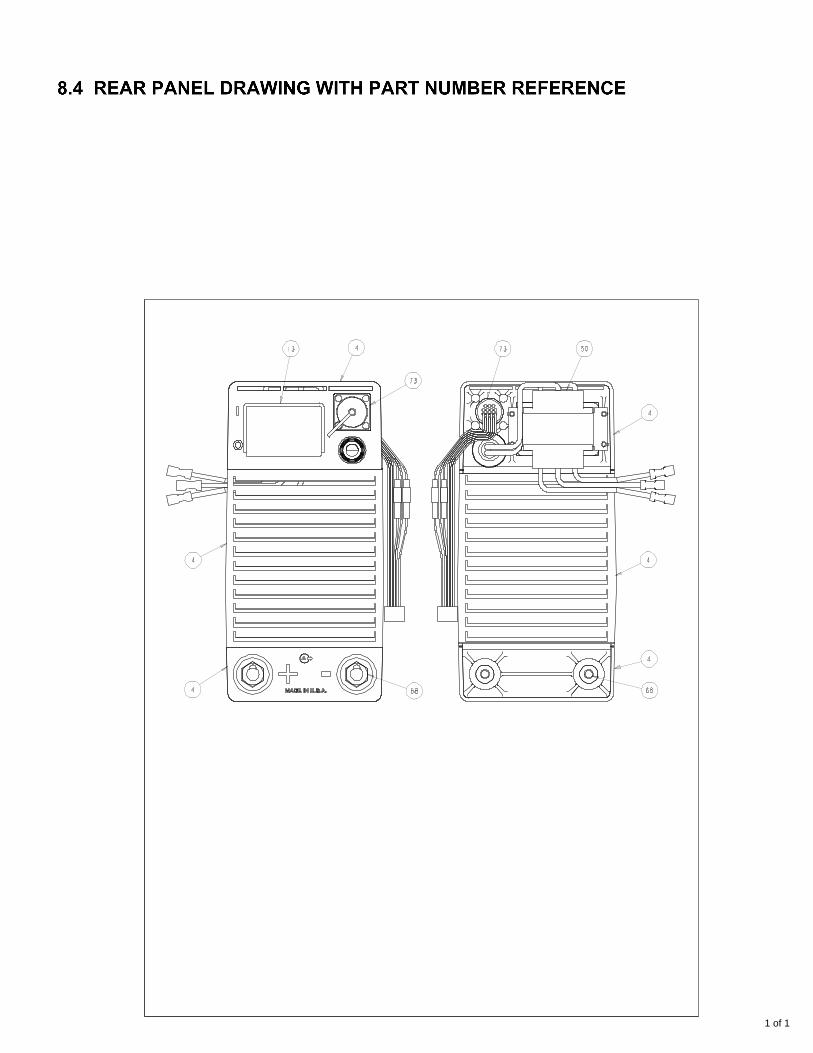
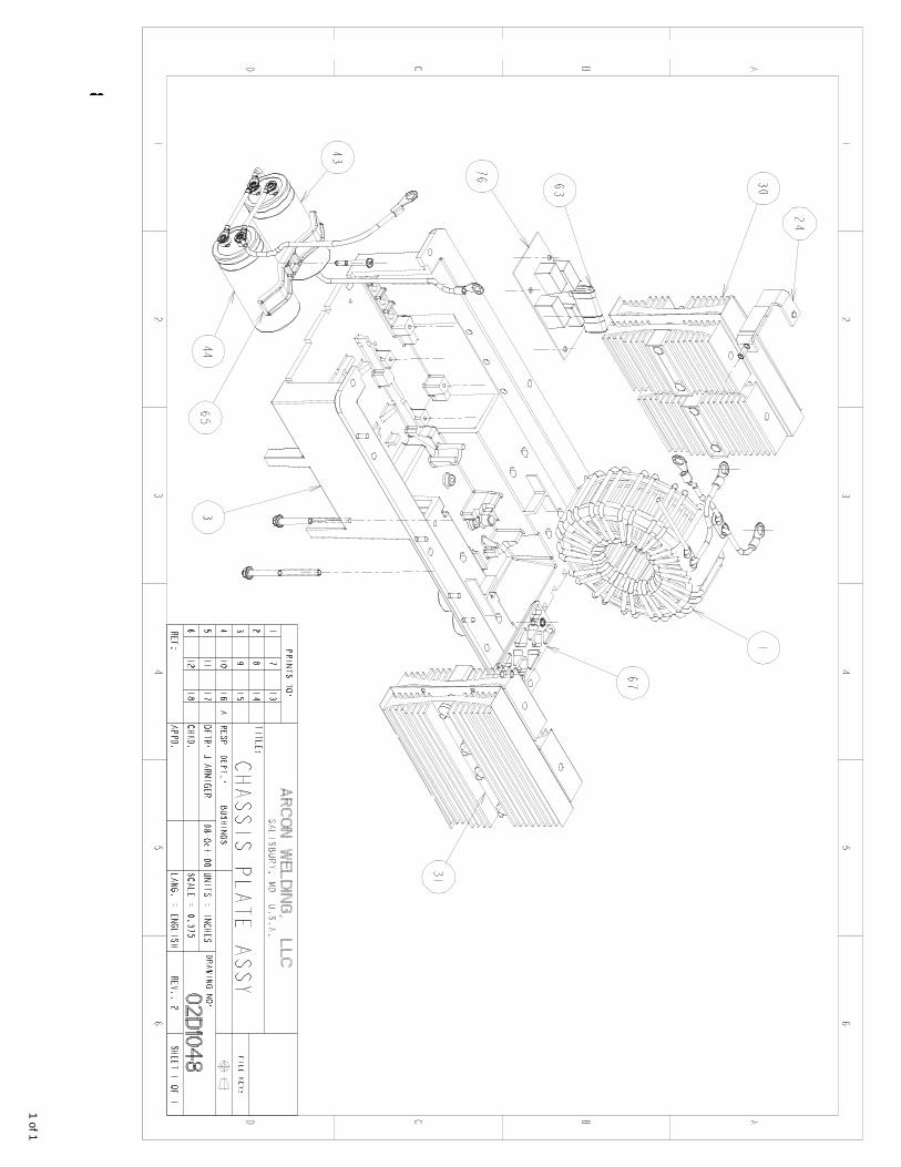
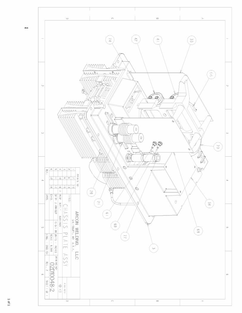
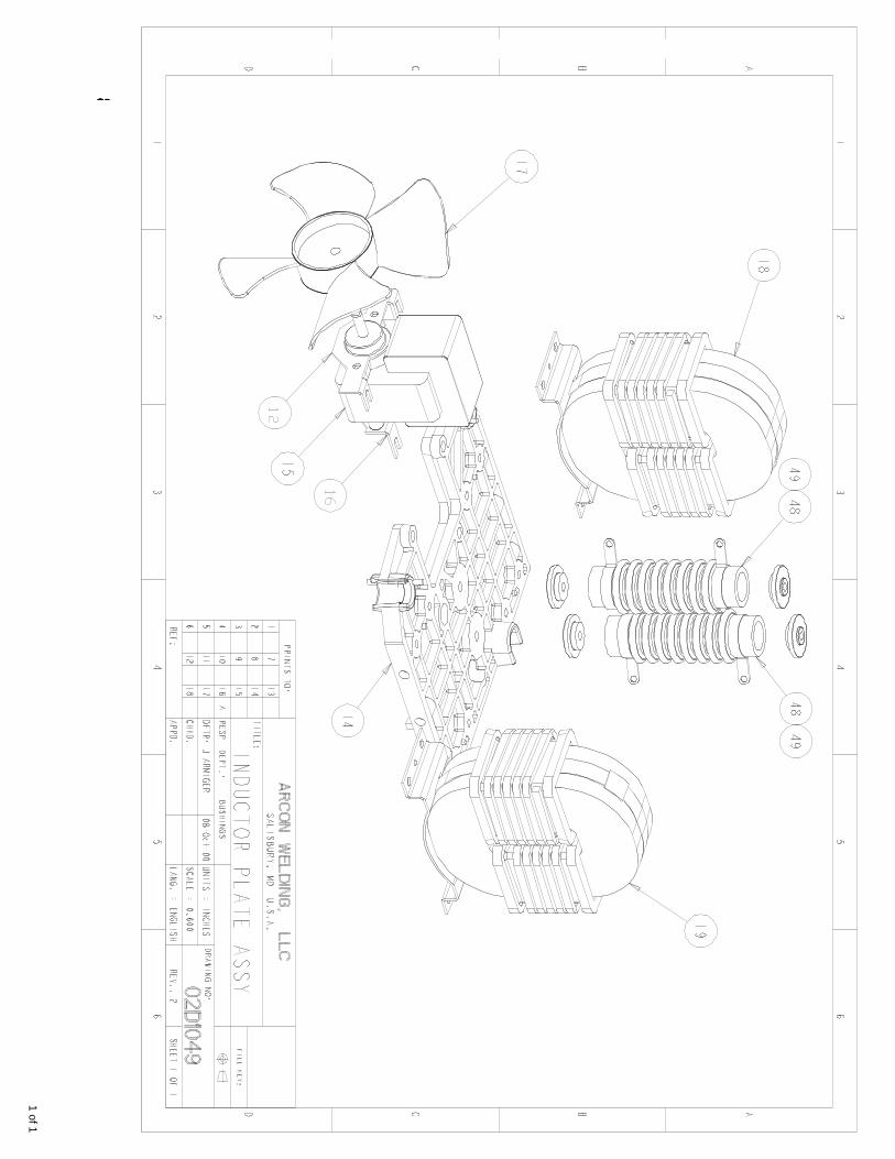
8. ELECTRICAL SPECIFICATIONS & DIAGRAMS 27 8.1 The principles of the inverter design (Figure 8.1) 28 8.2 Main Circuit Diagram 29 8.3 Front Panel Drawing with part references 30 8.4 Rear Panel Drawing with part references 31 8.5 Chassis Plate Drawing 1 with part references 32 8.6 Chassis Plate Drawing 2 with part references 33 8.7 Inductor Plate Drawing with part references 34
9. PARTS AND ACCESSORIES 9.1 Replacement Parts 35 9.2 Accessories 37

5
GENERAL INFORMATION
User Responsibility DABOTEK Welding warrants that The DT1200i will perform in accordance with the product description in this manual. The Factory Warranty will be null and void should the user attempt to operate The Studhorse after it has malfunctioned. Parts that are broken, missing or worn must be replaced immediately. DABOTEK Welding Equipment LLC or its Authorized Repair Center will perform warranty Repairs. The Studhorse or any of its parts must not be altered without the prior written approval of DABOTEK Welding Equipment LLC. Any malfunction resulting from improper use, faulty maintenance, physical damage, unapproved repair or alteration, shall be the sole responsibility of the user or owner. Any repair to improperly used or abused equipment by DABOTEK Welding Equipment LLC will be charged based on DABOTEK’s applicable hourly labor rate and current replacement part prices.
Manufacturer’s Limited Product Warranty DABOTEK Welding Equipment’s only warranty is that goods being sold will be free from defects in materials and workmanship. This express warranty is in lieu of any other warranties, either expressed or implied, and whether statutory or otherwise, including any implied warranty of merchantability or fitness for a particular purpose. The Manufacturer’s written warranty for The DT1200i Stud Welder has been included with your new machine, and is limited to defect in materials or workmanship. The original purchaser must furnish notice of defect or failure to DABOTEK Welding Equipment or one of DABOTEK’s authorized repair centers using an approved Warranty Claim Form. Forms can be downloaded
from the company Web Site at http://www.dabotek.com. The guarantee against
corrosion-related failures can be extended to five-years by completing the Registration Form. Any equipment that has been modified by any party other than DABOTEK Welding Equipment LLC, or equipment that has been improperly installed, improperly operated, misused based upon industry standards, improperly maintained or equipment which has been used for operation outside of specifications will not be covered under the manufacturer’s warranty. DABOTEK Welding Equipment shall in no way be liable for any consequential damages. DABOTEK Welding Equipment reserves the right to make engineering and/or part changes at any time, without notice, as improvements in quality or design are made. Owners and operators of The DT1200i should access the company Web site listed above to keep up-to-date with offerings, applications and technical suggestions.
SAFETY STANDARDS The DT1200i is designed and built to comply with the following safety standards: Underwriters Laboratories Standard UL551 Safety EN 60974-1 Degree of Enclosure Protection IP 24 in accordance with ISO 60529
• Protection against full penetration of solid foreign objects of 12.5mm diameter and larger.
• Protection against harmful effects from splashing water against the enclosure from any direction.
6
Please review all safety infomation in Section 1 very carefully before operating the machine.
This machine is protected against corrosion
DABOTEK’s time-proven Seahorse manufacturing process protects electrical components prone to failure from corrosion by design and using a compound containing cycloaliphatic-epoxides, tetramethylen-oxide and a cationic photo-initiator (commonly called conformal coating). This protection is incorporated as certain electrical components and printed circuit boards are produced to ensure excellent weathering and superior protection against humidity, moisture, dust, fungus and other contaminants. The Seahorse process used in this machine was developed and tested on oilrigs in the North Sea decades ago. This protection enhances reliability, prolongs component life and adds value to all of DABOTEK’s rugged line of portable welding power sources. Listed below are some of the steps DABOTEK Welding has taken to increase corrosive atmosphere resistance in this machine:
Transformer vacuum impregnated twice and dipped an additional time. Auxiliary transformer protected and coated to resist corrosion. Output board encapsulated in *repair-friendly material to eliminate the failures. Control board coated to protect against salt-water arc over. Input board coated to protect components from corrosion. Resistors replaced with porcelain-coated ceramic resistors. Fan motor totally encapsulated winding coil to withstand corrosive conditions. Terminal screws coated to prevent electrical arc-overs. This anti-corrosion process comes with DABOTEK’s five-year manufacturer’s guarantee against corrosion-related electrical failure within natural operating environments. This warranty begins the day the machine was shipped from the factory and does not apply to equipment used in man-made environments that produce chemical residue, dust or airborne debris of man-made substances, etc. Because the Seahorse protection is incorporated in the manufacturing process, any circuit modifications, repairs or component replacement with non-DABOTEK parts will void the Seahorse guarantee. Repair centers should contact the factory to obtain replacement parts for this machine. Customers that intend to submit a warranty request for corrosion related failure should contact the factory to obtain an RMA number before shipping their welder to the factory for evaluation.
7
1. SAFETY Safety is eveyone’s responsibility. DABOTEK designs every machine with safety in mind, and a
safe work environment depends largely on you. Do not install, operate, or repair this equipment without carefully reading this manual and observing all of the safety precautions mentioned. If there is a question, ask your supervisor! 1.1 Safety Symbols Every effort has been made to protect trained operators from injury or unnecessary risk. Certain symbols are used throughout this manual to call attention to safety-related information and instruction. The safety symbols in this manual have these meanings:
This symbol indicates Dangerous Situations. When this symbol is used in this manual, death or serious bodily harm is possible or probable if the corresponding preventative measures are not taken. Operators must take caution in the method and manner of handling or using the machine when this symbol is displayed.
1.2 Safety Precautions
Do not install, operate, or repair The Studhorse welding equipment without reading this manual and all safety precautions stated within! This machine was designed and built with operator safety in mind, but safety begins with you! Every effort has been made to protect the trained operator from injury. Please become familiar with the information in this manual to minimize the risk of shock or injury.
STUD WELDING CAN BE HAZARDOUS. ALWAYS PROTECT YOURSELF AND OTHERS FROM POSSIBLE INJURY OR DEATH. KEEP CHILDREN AWAY.
OPERATORS WHO WEAR A PACEMAKER SHOULD CONSULT WITH THEIR PHYSICIAN BEFORE OPERATING STUD WELDING EQUIPMENT.
THIS OPERATOR’S MANUAL SHOULD ALWAYS BE KEPT WITH THE STUDHORSE MACHINE FOR QUICK REFERENCE. ALL SAFETY WARNINGS, SIGNS AND STICKERS MUST STAY ATTACHED TO THE MACHINE. ALL OPERATORS MUST BE PROPERLY TRAINED AND PROTECTED BEFORE OPERATING THIS EQUIPMENT.

8
1.3 ELECTRIC SHOCK Precautionary measures must be taken to provide maximum protection against electrical shock.
Electric shock can injure or Kill!
WARNING
1. Do not touch live or energized electrical parts or store metallic objects near power. 2. Ground the work or metal to be welded to a good electrical (earth) ground. 3. Do not leave an energized machine unattended. 4. Never work in wet clothing, gloves or footwear. 5. Insulate yourself from work and ground using dry insulation. Make certain the insulation
is large enough to cover your full area of physical contact with work and ground. 6. Inspect all system components, protective equipment, cables, connectors and gas lines
prior to operating equipment. Never use cables that are longer than necessary. 7. When testing a live unit, use the one-hand method. Do not put both hands inside of the
unit. Keep one hand free. 8. Disconnect input power conductors from de-energized supply line before moving a
welding power source. 9. Always be sure the work cable makes a good electrical connection with the metal being
welded. The connection should be as close as possible to the area being welded. 10. Turn OFF welding power source before servicing unless the procedure specifically
requires an energized unit. 11. Never touch the energized stud or gun before discharging the stud to ground. 12. Never use the power source to provide heat for thawing frozen pipes.
1.4 ARC RAYS and EYE PROTECTION
Arc rays can injure eyes and burn skin. Arc flashes are painful. 1. Use a shield with the proper filter and cover plates to protect your eyes from sparks and
the rays of the arc when welding or while observing open arc welding. 2. Use protective clothing specifically intended for work with welding equipment. It should
be made of durable flame-resistant material to provide ample protection from the arc rays.
3. Protect other nearby workers with suitable, non-flammable screening. Caution other workers not to watch the arc nor expose themselves to the arc rays or to hot spatter or metal.
9
1.5 FUMES and OXYGEN DEPLETION
Only weld in areas or rooms where adequate ventilation of weld gases is possible, and where there are not fire, smoke or explosion hazards.
1. When working in a confined space always have trained support personnel nearby. Welding fumes and gases can displace air and lower the oxygen level causing injury or death. Be sure the breathing air is safe.
3 Do not weld in locations near degreasing, cleaning, or spraying operations. The heat and rays of the arcs can react with vapors to form highly toxic and irritating gases.
4 Do not weld on coated metals, such as galvanized, lead, or cadmium plated steel. The coating must be removed from the area to be welded. Coatings and metals containing above elements can generate toxic fumes when heated to welding temperature.
1.6 WELDING SPARKS
Heat from flames and arcs can start fires. Hot slag or sparks can also cause fires and explosions.
1. Remove all combustible materials from the work area or cover these materials with a
protective non-flammable tarp. Combustible materials include wood, fabrics, sawdust, liquid and gas fuels, solvents, paints and coatings, paper, etc.
2. Hot sparks or hot metal can fall through cracks or crevices in floors or wall openings and cause a hidden smoldering fire. Make certain that such openings are protected from hot sparks and metal.
1.7 ELECTRIC AND MAGNETIC FIELDS
Electric current flowing through any conductor causes localized Electro-Magnetic Fields (EMF). Welding and cutting current creates EMF around welding cables and welding machines.
1. Operators having pacemakers should consult their physician before welding. EMF may interfere with some type of pacemakers.
2. Exposure to EMF may have other health effects, which are unknown. 3. Operators should use the following procedures to minimize exposure to EMF:
a. Route the work cables together. Secure them with electrical tape when possible. b. Never coil the work cable around any part of your body. c. Do not place your body between the work cables. Route cables on the same side
of your body. d. Connect the work cable to the work piece as close as possible to the area being
welded. e. Keep welding power source and cables as far away from your body as possible.
4. Electromagnetic fields can irrevocable erase magnetic data carriers (computer memory, credit cards, security ID cards or data storage diskettes).
5. Electromagnetic fields may magnetize and damage watches or similar digital devices.
10
1.8 PROTECT YOURSELF AND OTHERS!
Some welding, cutting, and gouging processes are noisy and require ear protection. The arc, like the sun, emits ultraviolet (UV) and other radiation and may injure skin and eyes. Hot metal can cause burns. Training in the proper use of welding processes and equipment is essential to prevent accidents.
1. Always wear safety glasses with side shields in any work area. In conjunction with eye protection, welding helmets or face shields are also required.
2. Use a face shield fitted with the correct filter cover plates to protect your eyes, face, neck,
and ears from sparks and rays of the arc when operating or observing operations. Warn bystanders not to watch the arc and not to expose themselves to the rays of the electric arc or hot metal.
3. Wear flameproof type gloves, heavy long-sleeve shirt, cuff less trousers, and a welding
helmet or cap for hair protection, to protect against arc rays and hot sparks or hot metal. A flameproof apron may also be desirable as protection against radiated heat and sparks.
4. Hot sparks or metal can lodge in rolled up sleeves, trouser cuffs, or pockets. Sleeves and
collars should be kept buttoned, and open pockets eliminated from the front of clothing.
2. PRODUCT DESCRIPTION AND INFORMATION
2.1 INTRODUCTION TO THE DT1200I The DT1200i machines are portable drawn arc Stud welders using an inverter-type power supply to generate the output power. Both machines are currently available in the following models: 400V single voltage for European industry, 480V single voltage operating in three-phases; 575V single voltage operating in three-phases.
11
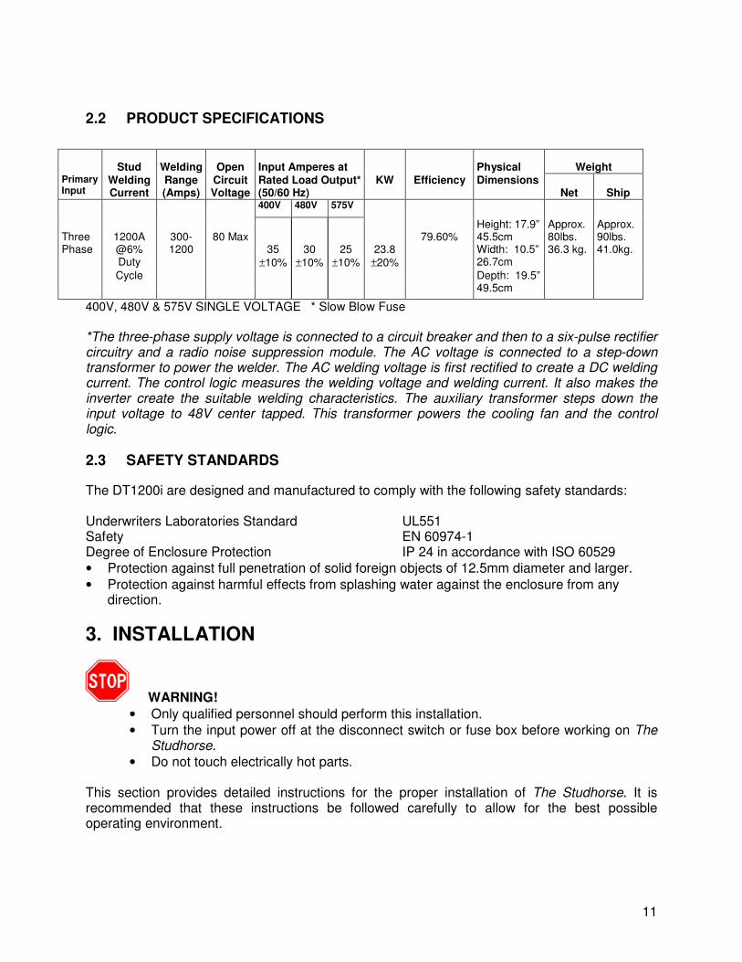
2.2 PRODUCT SPECIFICATIONS
Stud Welding Open Input Amperes at Physical Weight Primary Input
Welding Current
Range (Amps)
Circuit Voltage
Rated Load Output* (50/60 Hz)
KW
Efficiency Dimensions Net
Ship
400V 480V 575V
Three Phase
1200A @6% Duty
300- 1200
80 Max
35
±10%
30
±10%
25
±10%
23.8
±20%
79.60%
Height: 17.9” 45.5cm Width: 10.5” 26.7cm
Approx. 80lbs. 36.3 kg.
Approx. 90lbs. 41.0kg.
Cycle Depth: 19.5” 49.5cm
400V, 480V & 575V SINGLE VOLTAGE * Slow Blow Fuse
*The three-phase supply voltage is connected to a circuit breaker and then to a six-pulse rectifier circuitry and a radio noise suppression module. The AC voltage is connected to a step-down transformer to power the welder. The AC welding voltage is first rectified to create a DC welding current. The control logic measures the welding voltage and welding current. It also makes the inverter create the suitable welding characteristics. The auxiliary transformer steps down the input voltage to 48V center tapped. This transformer powers the cooling fan and the control logic.
2.3 SAFETY STANDARDS
The DT1200i are designed and manufactured to comply with the following safety standards: Underwriters Laboratories Standard UL551 Safety EN 60974-1 Degree of Enclosure Protection IP 24 in accordance with ISO 60529
• Protection against full penetration of solid foreign objects of 12.5mm diameter and larger.
• Protection against harmful effects from splashing water against the enclosure from any direction.
3. INSTALLATION
WARNING!
• Only qualified personnel should perform this installation.
• Turn the input power off at the disconnect switch or fuse box before working on The Studhorse.
• Do not touch electrically hot parts. This section provides detailed instructions for the proper installation of The Studhorse. It is recommended that these instructions be followed carefully to allow for the best possible operating environment.
12
3.1 Handling and Unpacking the Welder Since The DT1200i and machines weigh approximately 90 pounds in the shipping carton, no fork lift or crane is necessary to move the machine. The shipping carton has built-in reinforced handles to enable two people to easily transport the machine. Immediately upon receipt of the welder, inspect the shipping box for any damage and notify the carrier of such damage before accepting delivery. Then inspect The Studhorse for damage which may have occurred in transit. After removing the components from the shipping container(s), check the container for any loose parts. Remove all packing materials. Visually check all air passages of power source for any packing materials that may obstruct airflow through the welder. If the equipment is not being installed immediately, store it in a clean, dry, well-ventilated area until installation.
3.2 Selecting a Location The location of the power source should be carefully selected to ensure satisfactory and dependable service. Choose a location relatively close to a properly fused source of electrical power. Use care against toppling over if the machine is placed on a tilted surface or plane. It is important that the machine be located in an open area where air can circulate freely through the front and rear openings. If space is at a premium, leave at least 1 foot (300 mm) of clearance between the rear of the power source and wall or other obstruction.
3.3 Selecting Suitable Supply Cables The standard power input cable for The DT1200i welder is a high quality #14 Gauge cable that is 12.5 feet long. The secondary cables that connect the Stud gun to the power source vary with manufacturers, but is normally 1/0 diameter and 8 feet in length. Heavier 2/0 gauge cables can be used to extend the distance between the machine and work surface. Standard ground cables are 1/0 in diameter with 25 feet maximum length. Cable lengths can total 50 feet (total primary length plus total secondary length) using heavier 2/0 cables.
WARNING! • Only qualified personnel should perform this installation.
• Turn the input power off at the disconnect switch or fuse box before working on The Studhorse.
• Do not touch electrically hot parts.
3.4 Connecting input power The standard factory installed input power cable measures 12 ft. A longer power cable may have been provided as an option if requested.
13
The primary cable supplied with the power source has 4 conductors. When connecting an attachment plug or hard wiring to an electrical service box, connect the green/yellow wire to the ground. The remaining 3 conductors can be connected to the phases in any order. Once connected to the primary power, the power source must be turned OFF before the unit is moved.
3.5 Fuses and Circuit Breakers It is recommended that input fuse sizes be in accordance with the table below: Input Voltage Welder input
Maximum Amperage Recommended Fuse Capacity
400V (CE Version) 24 30A Time Delay (Slo-Blow) 460V-480V 20 30A Time Delay (Slo-Blow) 575V 18 30A Time Delay (Slo-Blow)
Table 2.0
3.6 Output cable connections
The standard supplied output connectors on output the rear panel are female Cam-Lok. Welders may have been supplied with Tweco type or Dinse (DIX) type if special ordered. Certain adapters can be supplied as an option. For connection to welding cables. Maximum recommended length is 50 feet 2/0 gun and ground cable.
3.7 Stud Guns There are several manufacturers of Stud welding guns. A Stud gun is shaped to fit in the hand, in the shape of a handgun, and is a semi-automatic stud welding tool. Guns vary in design, connection, weight, capacity and Duty Cycle. Only guns suitable for drawn arc Stud welding can be used and are available for Short Cycle, Standard Duty and Heavy-Duty use. The pin configuration of the gun must be compatible with The DT1200i. Units come standard with a 4-pin panel mounted control connector for the firing gun. The pistol grip switch initiates the stud current through the welding cables and, at the same time, powers the solenoid in the gun so that it retracts. Attach the gun cable to the (-) jack on the power supply and attach the ground clamp to the (+) jack on the power supply. There is very little to do when unpacking the Stud Welding gun. The gun should be complete with all the tools and accessories required for setup, adjustment and maintenance. Guns should be equipped with the correct chuck, ferrule grip and special accessories for each application. Operators should consult the Operation/Maintenance Manual from the Stud Gun manufacturer for complete instructions for safe operation and maintenance.
14
4. OPERATION
WARNING!
PLEASE READ CHAPTER 1 REGARDING SAFETY
4.1 General Description The 1200 Amp Studhorse power source combines time-proven technology with modern technology to provide high-quality performance. The digitally controlled SCR type inverter is very reliable in welding applications and capable of welding 5/8-inch full-base weld studs in a variety of applications. Duty Cycle at 1200 Amps is 6 per minute using 5/8-inch studs. 30 Amp Slo-Blow fuses provide protection for all input voltages.
4.2 Design Features The Studhorse power source is designed to be portable and easily transported to provide many benefits. No crane or special lifting devices are required to move or maintain the machine. The machine provides Constant Power output with Inverter-smooth arc, incorporating digitally controlled start/stop with no mechanical contactor. Other features include regulated output, step-less weld power and time adjustment, short-circuit protection, automatic line voltage protection and 5-zones of thermal protection.
4.3 Operational Controls and Settings – also refer to Figure 4.1
4.3.1 Circuit Breaker (Power On/Off)
The Circuit Breaker serves as the main input power switch and located on the control panel at the rear of the machine. Move the switch lever up to the ON position to start the machine. The Power-On indicator light will show that input power is being supplied to the machine.
4.3.2 Digital Meter on The DT1200i model
The digital current and timer meter displays current when the push button toggle switch is pushed once, and displays time when pushed in again.
After switching on the input power to the machine, the four-digit display shows the operational mode PA. The display shows the actual Current for three seconds after each Stud has been welded. The Current setting is displayed as ”(X)XXX” and actual Current is displayed as ”(X)XXX”.
If display flashes, the machine has exceeded its temperature limits. Wait a few minutes until the display has stopped flashing, and you can resume welding.
15
4.3.3 Setting the Welding Current and Time
The Current is controlled by using a microprocessor with an auto tuning function. Pressing the push-button switch on the front panel toggles the display presentation between Current and Time. There are separate (potentiometer) controls for setting the Current and the Time.
When the current value is set to 1200 Amps and a stud is welded, the actual current delivered (measured value) is displayed after completion of the stud. This current is shown flashing for 6 seconds. Thereafter, the average between the set value and the measured value is displayed.
Continued on next page.
For example:
If a value of 1000 Amps is entered into the display and the measured value of 1400 Amps is flashed after shooting a stud, 1200 Amps is displayed 6 seconds later. If the stud’s height reduction is correct, the 1200 Amps is maintained. If the height reduction is excessive, the 1400 Amps is reduced to 1000 Amps and measured current will be 1100 Amps. Normally the difference between “set” and “measured” is less and only one stud is needed for tuning in process.
The measured current may fluctuate up to 5 % (60 Amps @1200 Amps) dependent on the surface which is welded on and the angle of the stud. Typical variations from stud to stud may be a low as 1% or 12 Amps.
The Stud Time can be set from 0.05 seconds to 2.00 seconds with 0.01 second accuracy in .01 second increments using the Time control switch.
4.3.4 Setting the DT1200 (non-Digital)
The DT1200 (non-digital) model is always in ”P” mode, and no other mode is available.
4.3.5 Process for various Stud welding positions
Drawn Arc Stud Welding allows weldable 1/8” to 5/8” diameter Studs made of non-alloyed, alloyed, stainless and heat-resistant steels to suitable base materials. The following is a guide for welding positions using the DT1200 and DT1200i machines: Stud Welding Minimum Welding Process Stud Diameter Plate Thickness Position With a Ceramic 1/4” to 5/8” One (1/4”) Quarter Horizontal Ferrule Inch Vertical Overhead Using Inert Gas 1/4 to ½” One (1/4”) Quarter Horizontal Inch Only Short Cycle Less than ½” 16 Gauge Horizontal Vertical Overhead
16
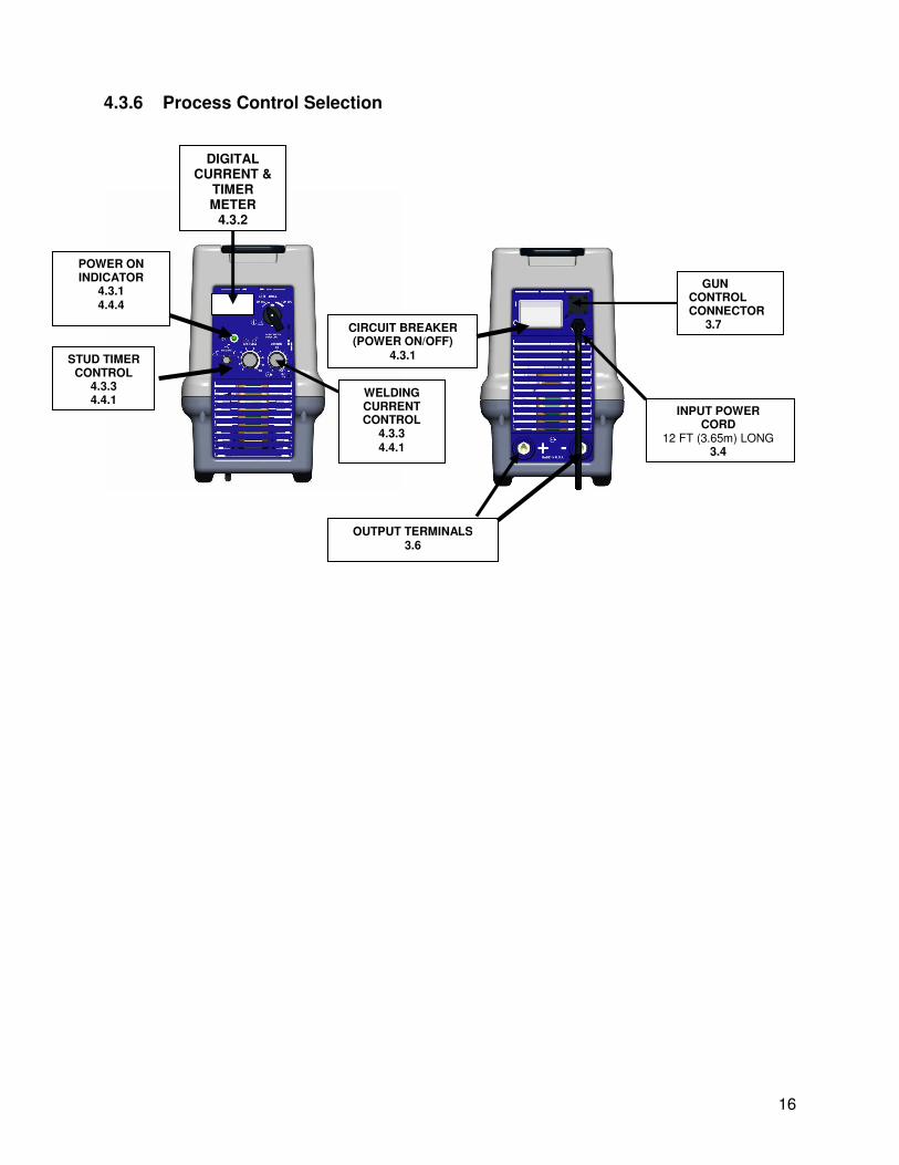
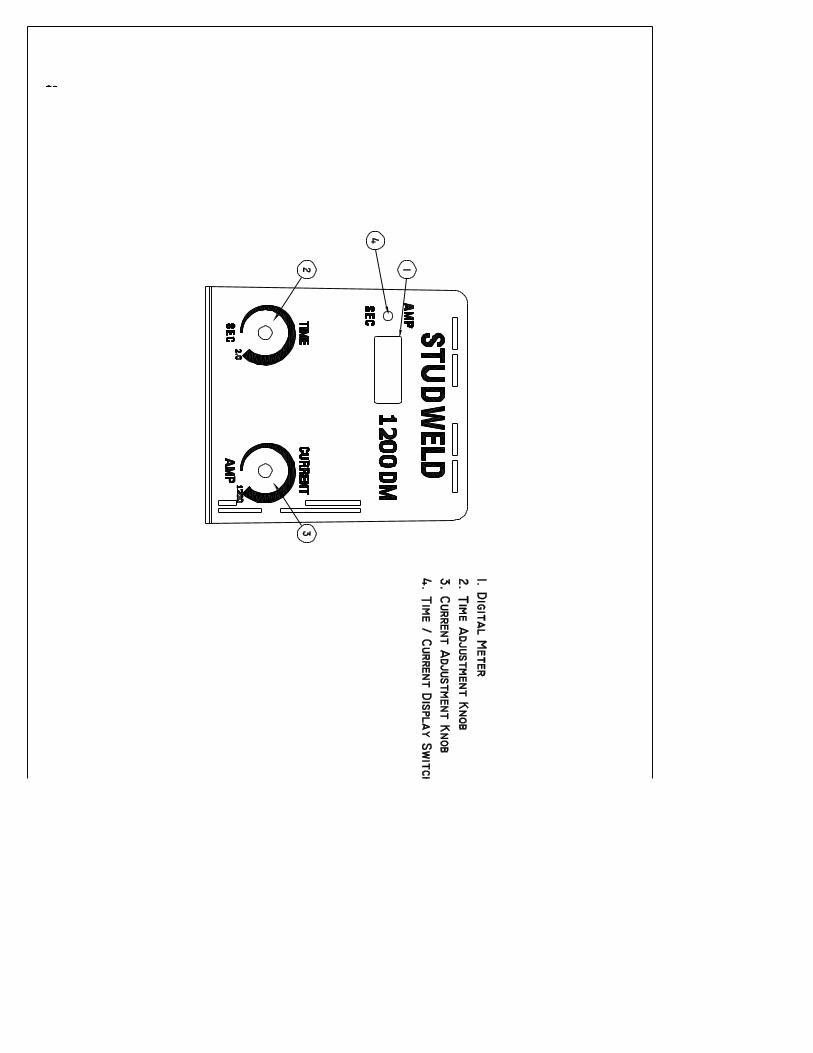
4.3.6 Process Control Selection
FIGURE 4.1
POWER ON INDICATOR
4.3.1 4.4.4
WELDING CURRENT CONTROL
4.3.3 4.4.1
STUD TIMER CONTROL
4.3.3 4.4.1
CIRCUIT BREAKER (POWER ON/OFF)
4.3.1
OUTPUT TERMINALS 3.6
INPUT POWER CORD
12 FT (3.65m) LONG 3.4
GUN CONTROL CONNECTOR 3.7
DIGITAL CURRENT &
TIMER METER
4.3.2
17
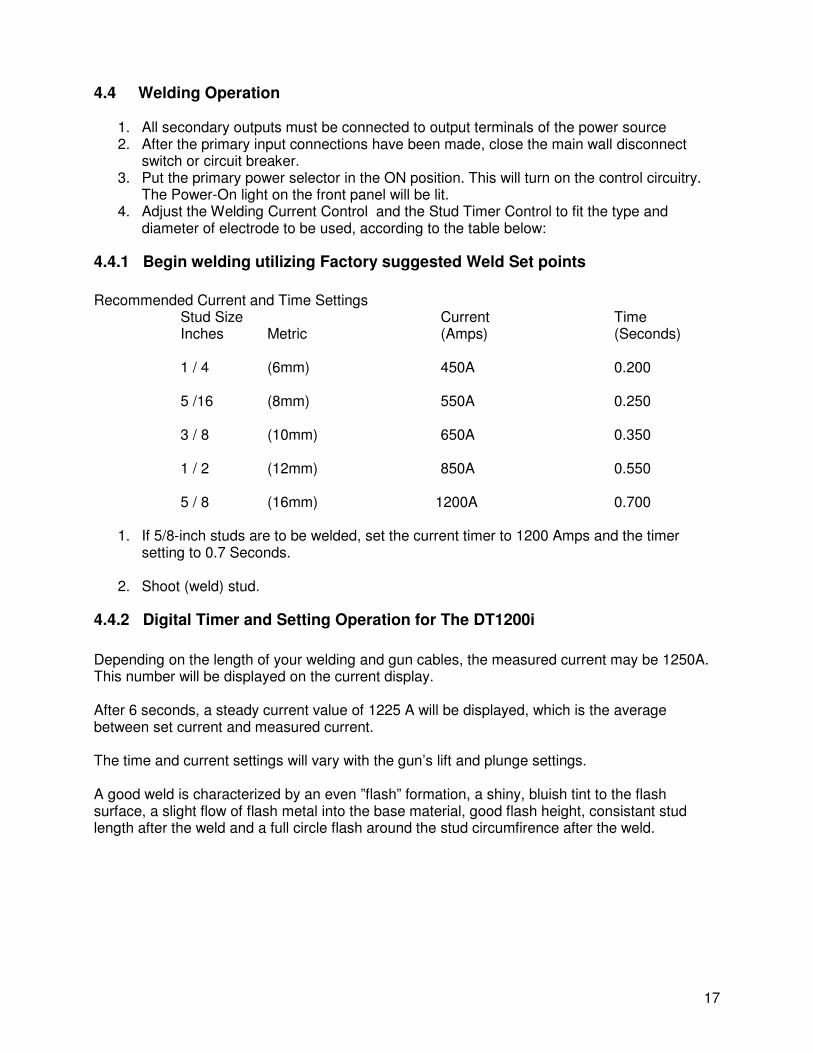
4.4 Welding Operation
1. All secondary outputs must be connected to output terminals of the power source 2. After the primary input connections have been made, close the main wall disconnect
switch or circuit breaker. 3. Put the primary power selector in the ON position. This will turn on the control circuitry.
The Power-On light on the front panel will be lit. 4. Adjust the Welding Current Control and the Stud Timer Control to fit the type and
diameter of electrode to be used, according to the table below:
4.4.1 Begin welding utilizing Factory suggested Weld Set points
Recommended Current and Time Settings
Stud Size Current Time Inches Metric (Amps) (Seconds)
1 / 4 (6mm) 450A 0.200 5 /16 (8mm) 550A 0.250 3 / 8 (10mm) 650A 0.350 1 / 2 (12mm) 850A 0.550 5 / 8 (16mm) 1200A 0.700
1. If 5/8-inch studs are to be welded, set the current timer to 1200 Amps and the timer
setting to 0.7 Seconds.
2. Shoot (weld) stud.
4.4.2 Digital Timer and Setting Operation for The DT1200i
Depending on the length of your welding and gun cables, the measured current may be 1250A. This number will be displayed on the current display. After 6 seconds, a steady current value of 1225 A will be displayed, which is the average between set current and measured current. The time and current settings will vary with the gun’s lift and plunge settings. A good weld is characterized by an even ”flash” formation, a shiny, bluish tint to the flash surface, a slight flow of flash metal into the base material, good flash height, consistant stud length after the weld and a full circle flash around the stud circumfirence after the weld.
18
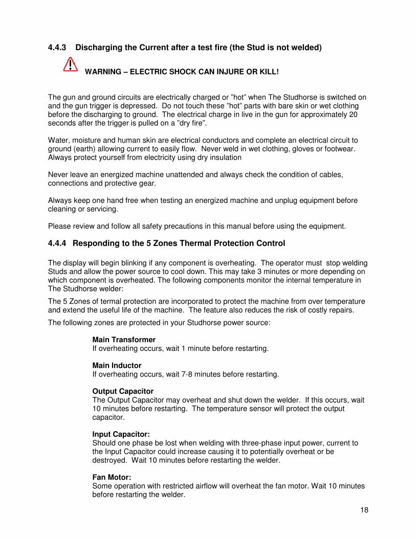
4.4.3 Discharging the Current after a test fire (the Stud is not welded)
WARNING – ELECTRIC SHOCK CAN INJURE OR KILL!
The gun and ground circuits are electrically charged or ”hot” when The Studhorse is switched on and the gun trigger is depressed. Do not touch these ”hot” parts with bare skin or wet clothing before the discharging to ground. The electrical charge in live in the gun for approximately 20 seconds after the trigger is pulled on a ”dry fire”. Water, moisture and human skin are electrical conductors and complete an electrical circuit to ground (earth) allowing current to easily flow. Never weld in wet clothing, gloves or footwear. Always protect yourself from electricity using dry insulation Never leave an energized machine unattended and always check the condition of cables, connections and protective gear. Always keep one hand free when testing an energized machine and unplug equipment before cleaning or servicing. Please review and follow all safety precautions in this manual before using the equipment.
4.4.4 Responding to the 5 Zones Thermal Protection Control
The display will begin blinking if any component is overheating. The operator must stop welding Studs and allow the power source to cool down. This may take 3 minutes or more depending on which component is overheated. The following components monitor the internal temperature in The Studhorse welder:
The 5 Zones of termal protection are incorporated to protect the machine from over temperature and extend the useful life of the machine. The feature also reduces the risk of costly repairs.
The following zones are protected in your Studhorse power source:
Main Transformer If overheating occurs, wait 1 minute before restarting.
Main Inductor If overheating occurs, wait 7-8 minutes before restarting.
Output Capacitor The Output Capacitor may overheat and shut down the welder. If this occurs, wait 10 minutes before restarting. The temperature sensor will protect the output capacitor. Input Capacitor: Should one phase be lost when welding with three-phase input power, current to the Input Capacitor could increase causing it to potentially overheat or be destroyed. Wait 10 minutes before restarting the welder. Fan Motor: Some operation with restricted airflow will overheat the fan motor. Wait 10 minutes before restarting the welder.
19
5. VISUAL INSPECTION
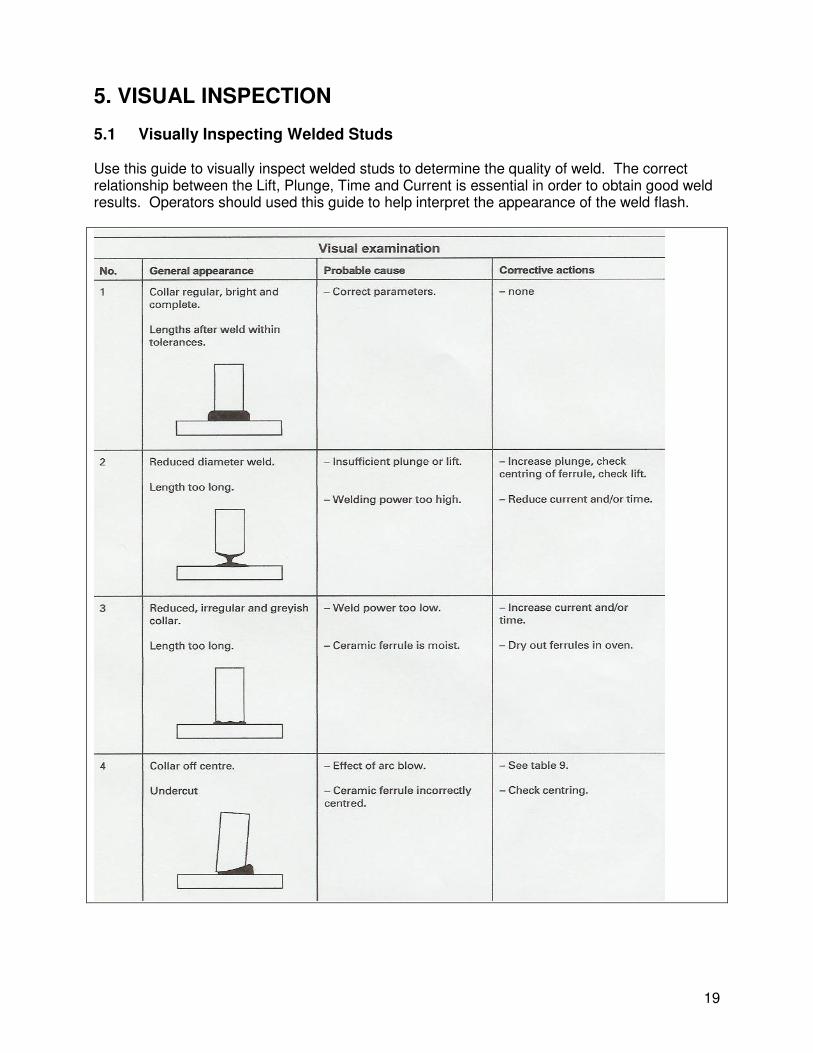
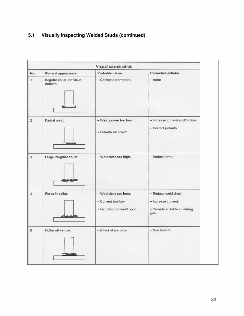
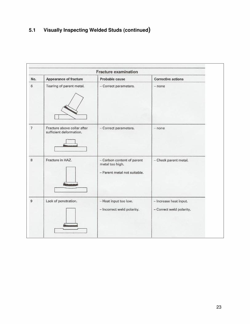
5.1 Visually Inspecting Welded Studs Use this guide to visually inspect welded studs to determine the quality of weld. The correct relationship between the Lift, Plunge, Time and Current is essential in order to obtain good weld results. Operators should used this guide to help interpret the appearance of the weld flash.

20
5.1 Visually Inspecting Welded Studs (continued)

21
5.1 Visually Inspecting Welded Studs (continued)
22
5.1 Visually Inspecting Welded Studs (continued)
23
5.1 Visually Inspecting Welded Studs (continued)
24
6. MAINTENANCE & REPAIR
WARNING!
Please see Chapter 1 regarding Safety
• Turn the input power OFF before working on any DABOTEK stud welder.
• Do not touch electrically live parts or electrode with your skin or wet clothing
• Insulate yourself from work and ground
• Always wear dry insulating gloves
• Have an electrician install the DABOTEK stud welder.
• An authorized DABOTEK Service Center must do all maintenance and repairs that require opening the case.
If The Studhorse does not operate properly, stop work immediately and investigate the cause of the malfunction. Please note: Opening up the case voids the Warranty. Maintenance and repair should only be performed by an authorized DABOTEK Service Center, or by the factory. Do not permit untrained persons to inspect, clean, or repair The Studhorse. Please call the factory for the location of the Authorized DABOTEK Service Center nearest you. Since there are no moving parts other than the fan in the power source, basic preventive maintenance only involves keeping the welder clean and free from metallic dust. Periodically, you should ask your Authorized Service Center to remove the cover from the case, remove accumulated dust and dirt from the air passages and the interior components, using clean low-pressure air. It is imperative that the air passages to the interior of the unit be free of dirt to ensure adequate circulation of cooling air, especially over the rectifier bridge plates. The frequency of cleaning will depend on the location of the unit, the amount of dust in the atmosphere and number of operating hours. Operators are encouraged to check the following to maintain The Studhorse power supply: 1. Visually inspect the case, panels, handles and cables for damage, which may occur in transit
and in normal use. 2. Check the machine for any loose or damaged parts. 3. Check air passages of power source for any debris that may obstruct airflow through the
welder. 4. Monitor and schedule having the machine cleaned with compressed air by an authorized service center.
25
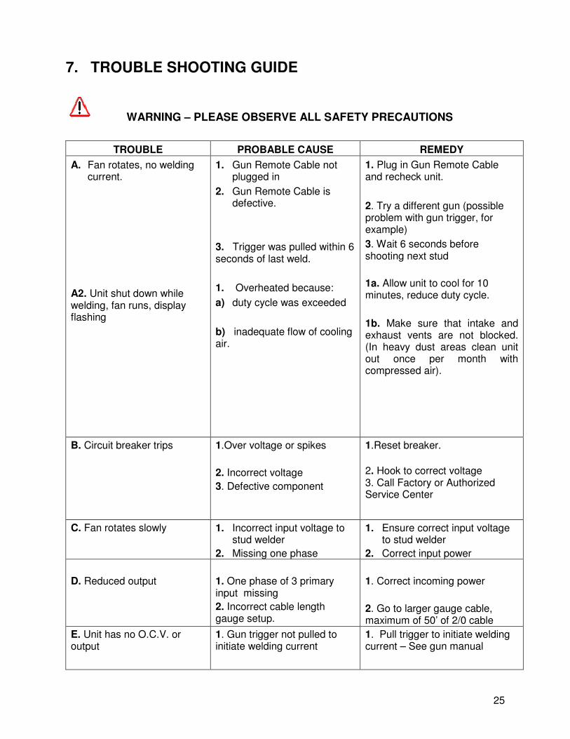
7. TROUBLE SHOOTING GUIDE
WARNING – PLEASE OBSERVE ALL SAFETY PRECAUTIONS
TROUBLE PROBABLE CAUSE REMEDY
A. Fan rotates, no welding current.
A2. Unit shut down while welding, fan runs, display flashing
1. Gun Remote Cable not plugged in
2. Gun Remote Cable is defective.
3. Trigger was pulled within 6 seconds of last weld.
1. Overheated because:
a) duty cycle was exceeded
b) inadequate flow of cooling air.
1. Plug in Gun Remote Cable and recheck unit.
2. Try a different gun (possible problem with gun trigger, for example)
3. Wait 6 seconds before shooting next stud
1a. Allow unit to cool for 10 minutes, reduce duty cycle.
1b. Make sure that intake and exhaust vents are not blocked. (In heavy dust areas clean unit out once per month with compressed air).
B. Circuit breaker trips 1.Over voltage or spikes
2. Incorrect voltage
3. Defective component
1.Reset breaker.
2. Hook to correct voltage 3. Call Factory or Authorized Service Center
C. Fan rotates slowly
1. Incorrect input voltage to stud welder
2. Missing one phase
1. Ensure correct input voltage to stud welder
2. Correct input power
D. Reduced output
1. One phase of 3 primary input missing
2. Incorrect cable length gauge setup.
1. Correct incoming power
2. Go to larger gauge cable, maximum of 50’ of 2/0 cable
E. Unit has no O.C.V. or output
1. Gun trigger not pulled to initiate welding current
1. Pull trigger to initiate welding current – See gun manual

26
TROUBLE PROBABLE CAUSE REMEDY
F. “E10” flashing on display 1. No arc initiated when trigger was pulled between stud and work piece.
2. Unit was dry fired, e.g. the gun with stud was not pressed against grounded piece of metal
3. Trigger was pulled with gun in the air
1. Clean surface
2. Read gun manual for procedure.
3. Read gun manual for procedure.
G. Display has fluctuating amperage levels
H. Display is flashing
1. Unit is self-calibrating and will complete calibration after 2-4 studs.
1. One of 5-temperature zones has overheated
1. Proceed after calibration.
1. Wait for several minutes for
welder to cool down and display
to stop flashing
I. Fan not working 1. Fan overheated
1. Allow unit to cool down for at least 10 minutes

27
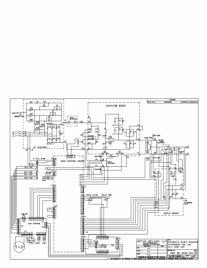
8. ELECTRICAL SPECIFICATIONS & DIAGRAMS
Circuit breaker The 3 phase elecric input power is connected to circuit breaker (K). CF Assembly The CF assembly has three functions: a six-pulse rectifier, suppression of elector-magnetic interference (EMI) and suppression of input voltage surges from the power lines. Rectifier The input rectifier consists of the power diodes CR1 to CR6. MOVs (Metal Oxide Varistors) If the machine is subject to a voltage surge btween phases, the diodes are protected by MOVs. MOVs are used from phase to ground (RV1, RV3, and RV6), and also between phases (RV2, RV4, and RV5). The phase to ground MOV protects the diode from a voltage surge between phase and ground. MOVs RV1 to RV6 protect the machine from high voltage surges. MOV RV7 is capable of withstanding surges of up to 40,000 Amps. EMI (Electro Magnetic Interference) The Electro Magnetic Interference from the inverter is suppressed by two capacitors in parallel between phase and neutral. These capacitors (C2, C3, C5, C6, C7 and C8) must be of type X to be allowed to be connected between phases and also to comply with the European community CE norms. The type X capacitors are connected to a common point, making it a virtual neutral. This point is connected to safety ground via two type Y capacitors and one 33-ohm resistor. The capacitors must be of a very reliable (HiRel) version, type Y, as a malfunction might make a welding machine in a steel case carry 480 V AC and therefore could be life threatening to the operator . The 480 V version of The Studhorse must have two type Y capacitors in series to comply with the CE norms and be allowed to be sold to the European Community (EC). The T1 auxiliary transformer is connected to two of the 3 phases. It is protected by an internal thermal switch (t) The surge resistors (R1 and R2) limits the current through the SCRs, should they fire at the same time. The circuit breaker limits the time the current is flowing through the resistors. Together they protect the SCR from destructive current should a cross firing of the SCRs occurs. Even though the case of The Studhorse welder is made of non-conductive fiberglass-reinforced Polyester, it meets and exceeds manufacturing and industry specifications.
28
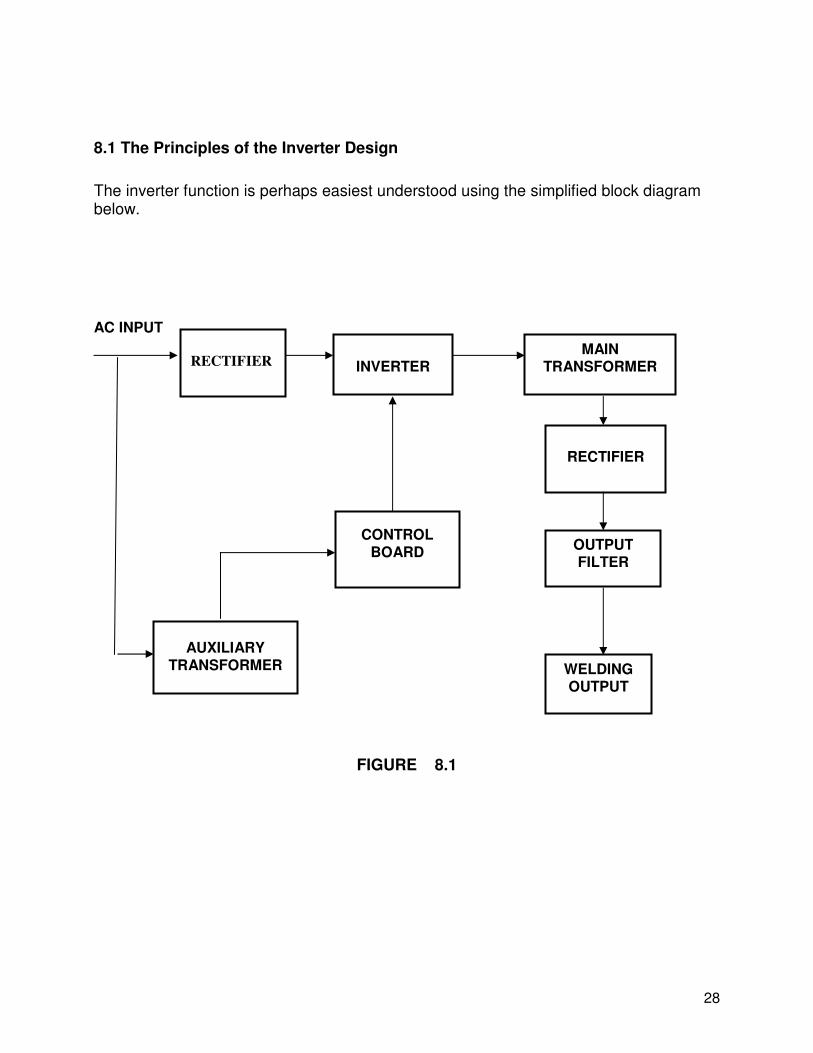
8.1 The Principles of the Inverter Design
The inverter function is perhaps easiest understood using the simplified block diagram below.
AC INPUT
FIGURE 8.1
RECTIFIER
INVERTER
MAIN TRANSFORMER
RECTIFIER
OUTPUT FILTER
CONTROL BOARD
AUXILIARY TRANSFORMER WELDING
OUTPUT
1 of 1
1 of 1
1 of 1
1 of 1
35
STUD WELDER
REPLACEMENT PARTS LIST
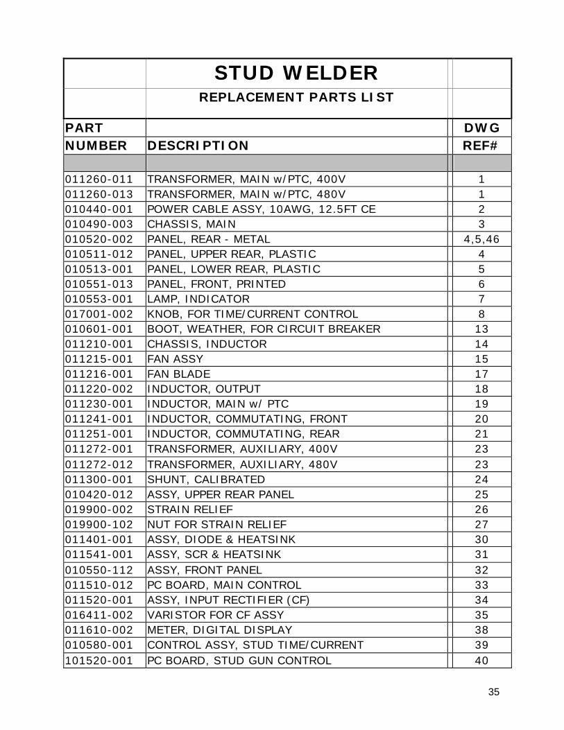
PART DWG NUMBER DESCRIPTION REF# 011260-011 TRANSFORMER, MAIN w/PTC, 400V 1 011260-013 TRANSFORMER, MAIN w/PTC, 480V 1 010440-001 POWER CABLE ASSY, 10AWG, 12.5FT CE 2 010490-003 CHASSIS, MAIN 3 010520-002 PANEL, REAR - METAL 4,5,46 010511-012 PANEL, UPPER REAR, PLASTIC 4 010513-001 PANEL, LOWER REAR, PLASTIC 5 010551-013 PANEL, FRONT, PRINTED 6 010553-001 LAMP, INDICATOR 7 017001-002 KNOB, FOR TIME/CURRENT CONTROL 8 010601-001 BOOT, WEATHER, FOR CIRCUIT BREAKER 13 011210-001 CHASSIS, INDUCTOR 14 011215-001 FAN ASSY 15 011216-001 FAN BLADE 17 011220-002 INDUCTOR, OUTPUT 18 011230-001 INDUCTOR, MAIN w/ PTC 19 011241-001 INDUCTOR, COMMUTATING, FRONT 20 011251-001 INDUCTOR, COMMUTATING, REAR 21 011272-001 TRANSFORMER, AUXILIARY, 400V 23 011272-012 TRANSFORMER, AUXILIARY, 480V 23 011300-001 SHUNT, CALIBRATED 24 010420-012 ASSY, UPPER REAR PANEL 25 019900-002 STRAIN RELIEF 26 019900-102 NUT FOR STRAIN RELIEF 27 011401-001 ASSY, DIODE & HEATSINK 30 011541-001 ASSY, SCR & HEATSINK 31 010550-112 ASSY, FRONT PANEL 32 011510-012 PC BOARD, MAIN CONTROL 33 011520-001 ASSY, INPUT RECTIFIER (CF) 34 016411-002 VARISTOR FOR CF ASSY 35 011610-002 METER, DIGITAL DISPLAY 38 010580-001 CONTROL ASSY, STUD TIME/CURRENT 39 101520-001 PC BOARD, STUD GUN CONTROL 40
36
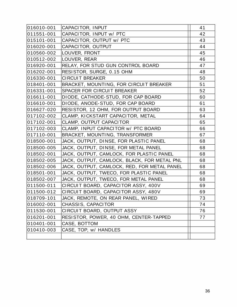
016010-001 CAPACITOR, INPUT 41 011551-001 CAPACITOR, INPUT w/ PTC 42 015101-001 CAPACITOR, OUTPUT w/ PTC 43 016020-001 CAPACITOR, OUTPUT 44 010560-002 LOUVER, FRONT 45 010512-002 LOUVER, REAR 46 016920-001 RELAY, FOR STUD GUN CONTROL BOARD 47 016202-001 RESISTOR, SURGE, 0.15 OHM 48 016330-001 CIRCUIT BREAKER 50 018401-001 BRACKET, MOUNTING, FOR CIRCUIT BREAKER 51 016331-001 SPACER FOR CIRCUIT BREAKER 52 016611-001 DIODE, CATHODE-STUD, FOR CAP BOARD 60 016610-001 DIODE, ANODE-STUD, FOR CAP BOARD 61 016627-020 RESISTOR, 12 OHM, FOR OUTPUT BOARD 63 017102-002 CLAMP, KICKSTART CAPACITOR, METAL 64 017102-001 CLAMP, OUTPUT CAPACITOR 65 017102-003 CLAMP, INPUT CAPACITOR w/ PTC BOARD 66 017110-001 BRACKET, MOUNTING, TRANSFORMER 67 018500-001 JACK, OUTPUT, DINSE, FOR PLASTIC PANEL 68 018500-005 JACK, OUTPUT, DINSE, FOR METAL PANEL 68 018502-001 JACK, OUTPUT, CAMLOCK, FOR PLASTIC PANEL 68 018502-005 JACK, OUTPUT, CAMLOCK, BLACK, FOR METAL PNL 68 018502-006 JACK, OUTPUT, CAMLOCK, RED, FOR METAL PANEL 68 018501-001 JACK, OUTPUT, TWECO, FOR PLASTIC PANEL 68 018502-007 JACK, OUTPUT, TWECO, FOR METAL PANEL 68 011500-011 CIRCUIT BOARD, CAPACITOR ASSY, 400V 69 011500-012 CIRCUIT BOARD, CAPACITOR ASSY, 480V 69 018709-101 JACK, REMOTE, ON REAR PANEL, WIRED 73 016002-001 CHASSIS, CAPACITOR 74 011530-001 CIRCUIT BOARD, OUTPUT ASSY 76 016201-001 RESISTOR, POWER, 40 OHM, CENTER-TAPPED 77 010401-001 CASE, BOTTOM 010410-003 CASE, TOP, w/ HANDLES
37
STUD WELDER ACCESSORIES
PART
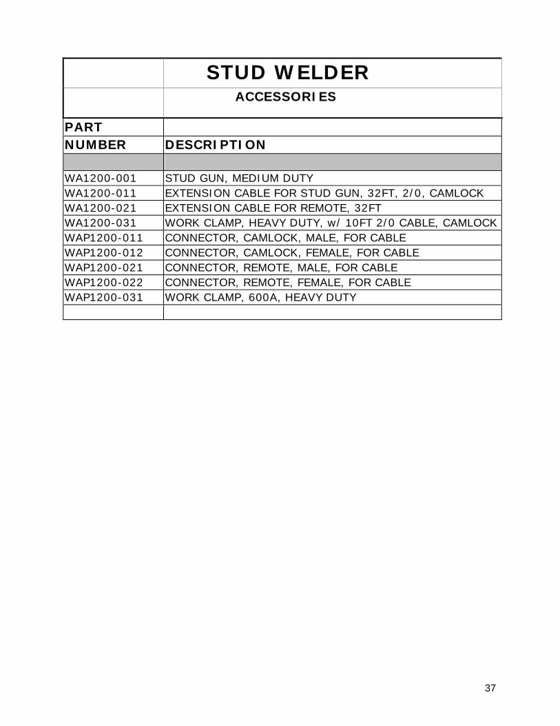
NUMBER DESCRIPTION WA1200-001 STUD GUN, MEDIUM DUTY WA1200-011 EXTENSION CABLE FOR STUD GUN, 32FT, 2/0, CAMLOCK WA1200-021 EXTENSION CABLE FOR REMOTE, 32FT WA1200-031 WORK CLAMP, HEAVY DUTY, w/ 10FT 2/0 CABLE, CAMLOCK WAP1200-011 CONNECTOR, CAMLOCK, MALE, FOR CABLE WAP1200-012 CONNECTOR, CAMLOCK, FEMALE, FOR CABLE WAP1200-021 CONNECTOR, REMOTE, MALE, FOR CABLE WAP1200-022 CONNECTOR, REMOTE, FEMALE, FOR CABLE WAP1200-031 WORK CLAMP, 600A, HEAVY DUTY