Embed Size (px)
Citation preview

MANUAL – INSTALLATION
Laboratory Space ControllerLSC Series
v200 – Issue Date: 03/26/15© 2015 Price Industries Limited. All rights reserved.
LABORATORY SPACE CONTROLLERTABLE OF CONTENTS
This mark indicates an important point for the proper function of the fume hood and the FHC. Improper installation or setup may cause unit failure and contamination of the laboratory space. Pay close attention to all caution points throughout this manual.
CAUTION
IMPORTANT NOTES
Application Support
678.578.7495
www.pricecriticalcontrols.com
Product Overview
General .........................................................................1
Laboratory Space Controller (LSC) Features .................1
Laboratory Space Controller EXP 1 Features ................2
Laboratory Space Controller EXP 2 Features ................2
Accessory Overview
Room Pressure Sensor (RPS) Features .........................3
Room Pressure Interface (RPI) Features ........................3
Thermostat Features .....................................................3
Installation and Mounting Instructions
Price Laboratory Space Controller (LSC)Step-by-Step Installation ...............................................4
Wiring Diagrams
Laboratory Space Controller – EXP 2 ............................5
Wiring a Network of Multiple Price Fume Hood Controllers .............................................6
Display Navigation
RPI Initial Start Up .........................................................7
Controller ......................................................................8
Service Menu ................................................................8
Wizard Menu .................................................................9
Timing Menu ...............................................................14
Remote Panel Menu ....................................................15
Input Menu ..................................................................16
Output Menu ...............................................................20
Network Menu ............................................................23
RPI Setup Menu ..........................................................24
Diagnostic Menu .........................................................26
Room Control Menu ....................................................27
Temperature Control Menu ..........................................31
LABORATORY SPACE CONTROLLER
1pricecriticalcontrols.com | LABORATORY SPACE CONTROLLER - Manual
PRODUCT OVERVIEW
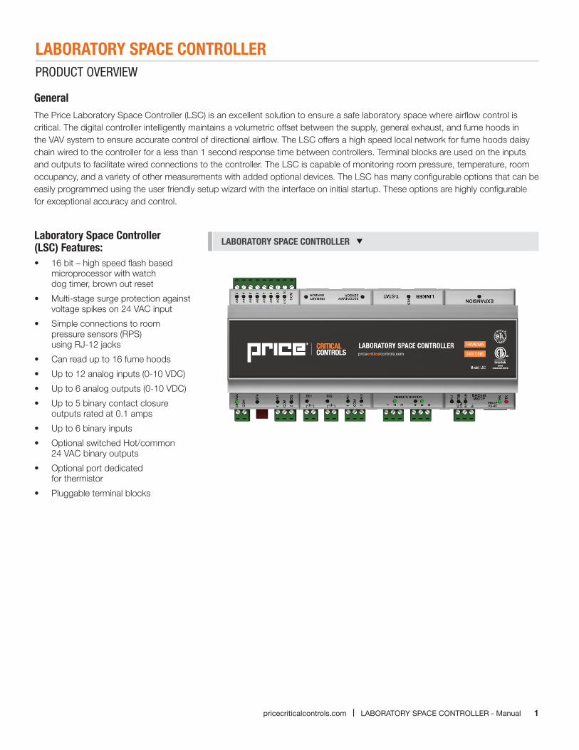
GeneralThe Price Laboratory Space Controller (LSC) is an excellent solution to ensure a safe laboratory space where airflow control is critical. The digital controller intelligently maintains a volumetric offset between the supply, general exhaust, and fume hoods in the VAV system to ensure accurate control of directional airflow. The LSC offers a high speed local network for fume hoods daisy chain wired to the controller for a less than 1 second response time between controllers. Terminal blocks are used on the inputs and outputs to facilitate wired connections to the controller. The LSC is capable of monitoring room pressure, temperature, room occupancy, and a variety of other measurements with added optional devices. The LSC has many configurable options that can be easily programmed using the user friendly setup wizard with the interface on initial startup. These options are highly configurable for exceptional accuracy and control.
LABORATORY SPACE CONTROLLER Laboratory Space Controller (LSC) Features:• 16 bit – high speed flash based
microprocessor with watch dog timer, brown out reset
• Multi-stage surge protection against voltage spikes on 24 VAC input
• Simple connections to room pressure sensors (RPS) using RJ-12 jacks
• Can read up to 16 fume hoods
• Up to 12 analog inputs (0-10 VDC)
• Up to 6 analog outputs (0-10 VDC)
• Up to 5 binary contact closure outputs rated at 0.1 amps
• Up to 6 binary inputs
• Optional switched Hot/common 24 VAC binary outputs
• Optional port dedicated for thermistor
• Pluggable terminal blocks
LABORATORY SPACE CONTROLLER
2 LABORATORY SPACE CONTROLLER - Manual | pricecriticalcontrols.com
PRODUCT OVERVIEW
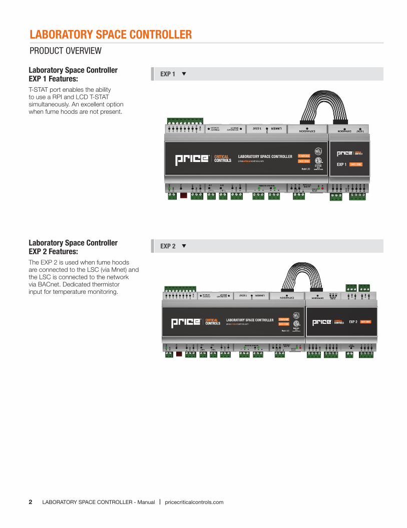
Laboratory Space Controller EXP 1 Features:T-STAT port enables the ability to use a RPI and LCD T-STAT simultaneously. An excellent option when fume hoods are not present.
Laboratory Space Controller EXP 2 Features:The EXP 2 is used when fume hoods are connected to the LSC (via Mnet) and the LSC is connected to the network via BACnet. Dedicated thermistor input for temperature monitoring.
EXP 1
EXP 2
LABORATORY SPACE CONTROLLER
3pricecriticalcontrols.com | LABORATORY SPACE CONTROLLER - Manual
ACCESSORY OVERVIEW
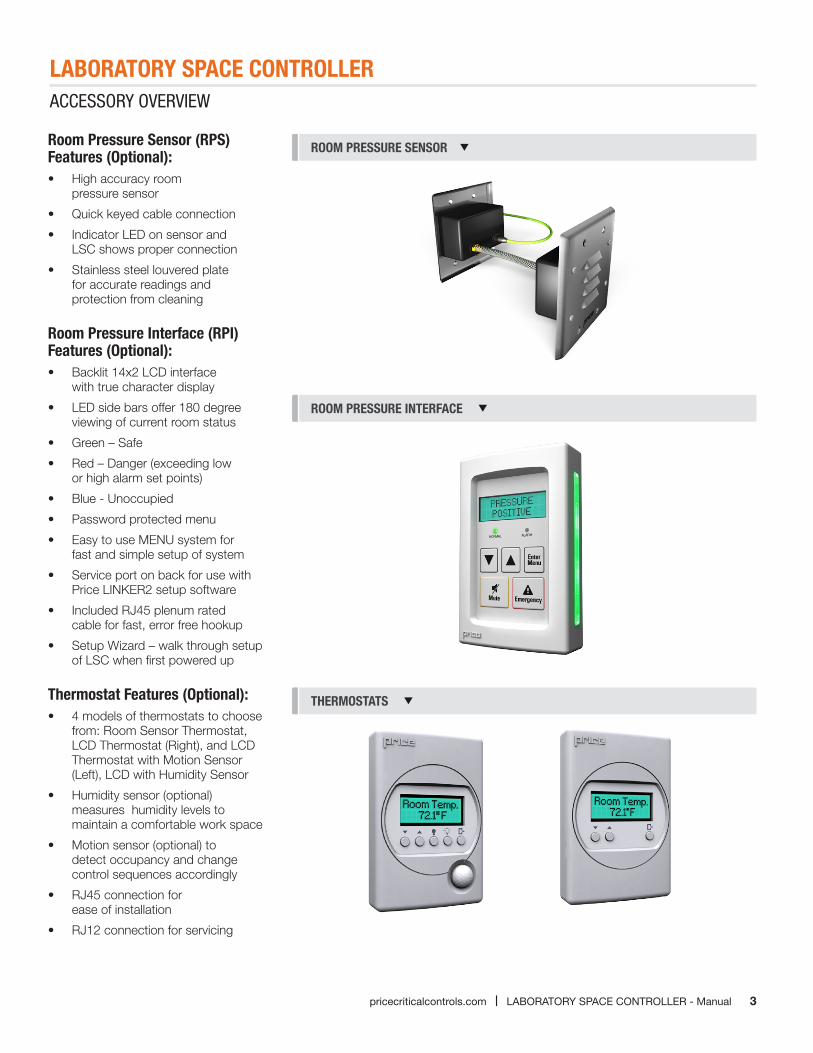
Room Pressure Sensor (RPS) Features (Optional):• High accuracy room
pressure sensor
• Quick keyed cable connection
• Indicator LED on sensor and LSC shows proper connection
• Stainless steel louvered plate for accurate readings and protection from cleaning
Room Pressure Interface (RPI) Features (Optional):• Backlit 14x2 LCD interface
with true character display
• LED side bars offer 180 degree viewing of current room status
• Green – Safe
• Red – Danger (exceeding low or high alarm set points)
• Blue - Unoccupied
• Password protected menu
• Easy to use MENU system for fast and simple setup of system
• Service port on back for use with Price LINKER2 setup software
• Included RJ45 plenum rated cable for fast, error free hookup
• Setup Wizard – walk through setup of LSC when first powered up
Thermostat Features (Optional):• 4 models of thermostats to choose
from: Room Sensor Thermostat, LCD Thermostat (Right), and LCD Thermostat with Motion Sensor (Left), LCD with Humidity Sensor
• Humidity sensor (optional) measures humidity levels to maintain a comfortable work space
• Motion sensor (optional) to detect occupancy and change control sequences accordingly
• RJ45 connection for ease of installation
• RJ12 connection for servicing
ROOM PRESSURE SENSOR
ROOM PRESSURE INTERFACE
THERMOSTATS
LABORATORY SPACE CONTROLLER
4 LABORATORY SPACE CONTROLLER - Manual | pricecriticalcontrols.com
INSTALLATION AND MOUNTING INSTRUCTIONS
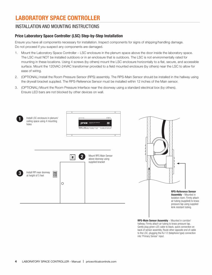
Price Laboratory Space Controller (LSC) Step-by-Step InstallationEnsure you have all components necessary for installation. Inspect components for signs of shipping/handling damage. Do not proceed if you suspect any components are damaged.
1. Mount the Laboratory Space Controller – LSC enclosure in the plenum space above the door inside the laboratory space. The LSC must NOT be installed outdoors or in an enclosure that is outdoors. The LSC is not environmentally rated for mounting in these locations. Using 4 screws (by others) mount the LSC enclosure horizontally to a flat, secure, and accessible surface. Mount the 120VAC-24VAC transformer provided to a field mounted enclosure (by others) near the LSC to allow for ease of wiring.
2. (OPTIONAL) Install the Room Pressure Sensor (RPS) assembly. The RPS-Main Sensor should be installed in the hallway using the drywall bracket supplied. The RPS-Reference Sensor must be installed within 12 inches of the Main sensor.
3. (OPTIONAL) Mount the Room Pressure Interface near the doorway using a standard electrical box (by others). Ensure LED bars are not blocked by other devices on wall.
1
2
Install LSC enclosure in plenum/ceiling space using 4 mounting holes
RPS-Reference Sensor Assembly – Mounted in Isolation room. Firmly attach air tubing (supplied) to brass pressure tap using supplied kink resistant tubing.
RPS-Main Sensor Assembly – Mounted in corridor/hallway. Firmly attach air tubing to brass pressure tap. Gently plug green c25 cable to black, quick connection on back of sensor assembly. Route other opposite end of cable to the LSC, plugging the RJ-12 (telephone type) connection into ‘Primary Sensor’ input.
Mount RPS Main Sensor above doorway using supplied bracket
3 Install RPI near doorway at height of 5 feet
LABORATORY SPACE CONTROLLER
5pricecriticalcontrols.com | LABORATORY SPACE CONTROLLER - Manual
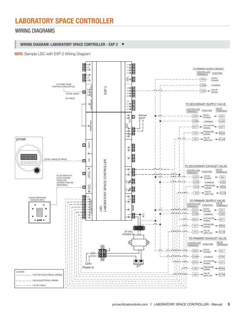
WIRING DIAGRAM: LABORATORY SPACE CONTROLLER - EXP 2
CAT5E CABLE
FIELD ELECTRICAL WIRING
FACTORY ELECTRICAL WIRINGLEGEND
LSC
PR
IMA
RY
SE
NS
OR
AN
ALO
G IN
PUTS
LINKER
RPI
EXP
ANSIO
N
BACnetMSTP
COM
1
2
BI1
BI2
BO
1
STA
COM
24VAC
3
2
1
5
4
6
2AO2
1AO1
BO
2
COM
RJ-
45P
RIC
EA/+
B/-BA
Cne
t
TX
RX
HLH
MS
/TP
NETTRM
FLTCOM
*
24 VACPOWER IN
3
4
5
6
7
8
9
10
COM
AO6
AO5
AO4
AO3
EXP
ANSIO
N
BO3
BO4
BO5
COM
CAT5E CABLE BY PRICE
STA
LAB
OR
ATO
RY
SP
AC
E C
ON
TRO
LLE
R
AI14
AI13
AI12
AI11
BI3
COM
BI4
BI5
COM
BI6
RX
TXFLT
FUM
E HO
OD
S
AI1
5TH
ER
M
CAT5E CABLE
BY PRICE
TO FUME HOODCONTROLLER(S)-(PFHC)
TO PRIMARY EXHAUST VALVE
TO PRIMARY SUPPLY VALVE
COM
AO1
AI9
AI5
COMMON
ACTUATORSIGNAL
PRESSURESIGNAL
VALVEAIRFLOW
COM
ACT
PRES
FLOW
TO SECONDARY SUPPLY VALVE
CONTROLLERTERMINALS FUNCTION
TO PRIMARY SUPPLY REHEAT
COM
AO1
AI7
AI3
COMMON
ACTUATORSIGNAL
PRESSURESIGNAL
VALVEAIRFLOW
COM
ACT
PRES
FLOW
COM
AO2
AI8
AI4
COMMON
ACTUATORSIGNAL
PRESSURESIGNAL
VALVEAIRFLOW
COM
ACT
PRES
FLOW
HOT 24V24VACPOWER
COM
AO5
COMMON
VALVESIGNAL
HOT24VACPOWER
TO SECONDARY EXHAUST VALVE
COM
AI10
AI6
COMMONPRESSURESIGNAL
VALVEAIRFLOW
COM
PRES
FLOW
HOT 24V24VACPOWER
SE
CO
ND
AR
YS
EN
SO
R
Power In120V
L1
N/L2
HOT 24V24VACPOWER
CONTROLLERTERMINALS FUNCTION
VALVETERMINALS
CONTROLLERTERMINALS FUNCTION
VALVETERMINALS
CONTROLLERTERMINALS FUNCTION
VALVETERMINALS
CONTROLLERTERMINALS FUNCTION
VALVETERMINALS
HOT 24V24VACPOWER
ROOM PRESSURE SENSOR (RPS)
PLUG AND PLAYRJ12/LOCKINGCIRCULARCONNECTION ONSENSOR(S)
EX
P 2
C
PROJECT :
SUBMITTAL DATE:
ENGINEER:
CUSTOMER:
SPEC. SYMBOL:
R
R Control SequenceNumber
REVOFSHEET
PCC00002
2014/03/31
14 42 0
CRITICAL CONTROLS
Reference #: PTR1310429
CRITICAL CONTROLSPCC00075-14
Copyright PRICE INDUSTRIES 2013
WIRING DIAGRAMS
NOTE: Sample LSC with EXP 2 Wiring Diagram
LABORATORY SPACE CONTROLLER
6 LABORATORY SPACE CONTROLLER - Manual | pricecriticalcontrols.com
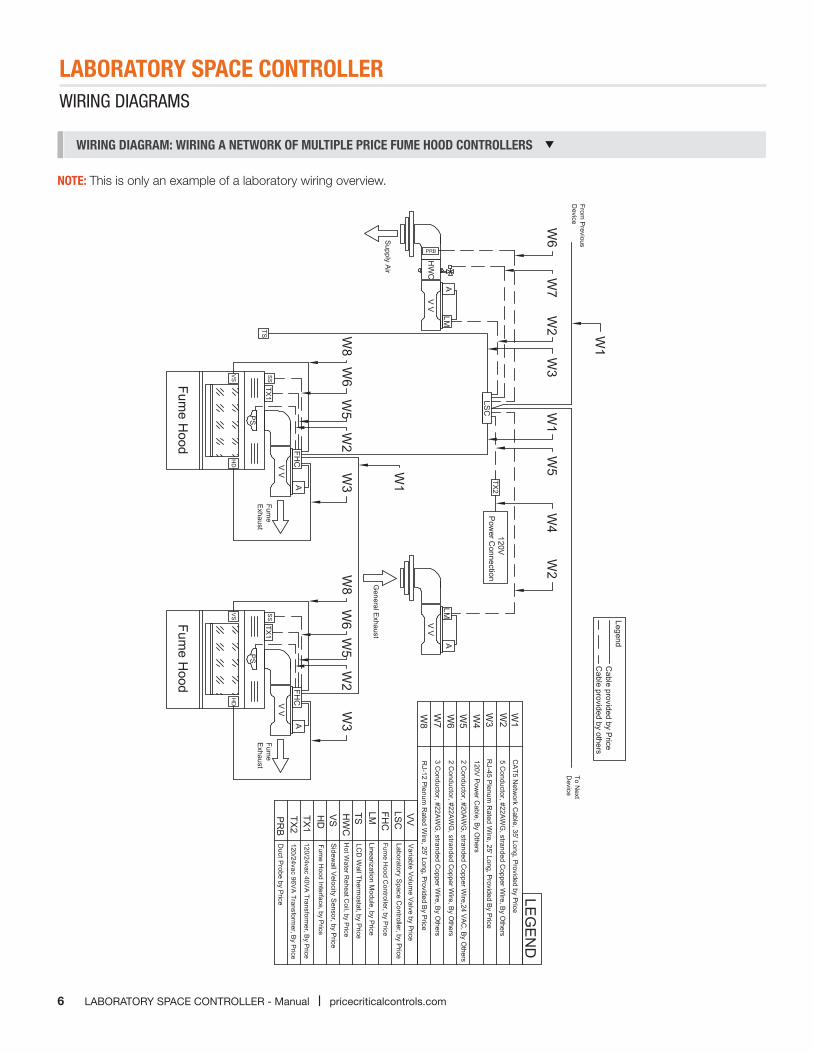
WIRING DIAGRAM: WIRING A NETWORK OF MULTIPLE PRICE FUME HOOD CONTROLLERS
WIRING DIAGRAMS
NOTE: This is only an example of a laboratory wiring overview.
LABORATORY SPACE CONTROLLER
7pricecriticalcontrols.com | LABORATORY SPACE CONTROLLER - Manual
DISPLAY NAVIGATION
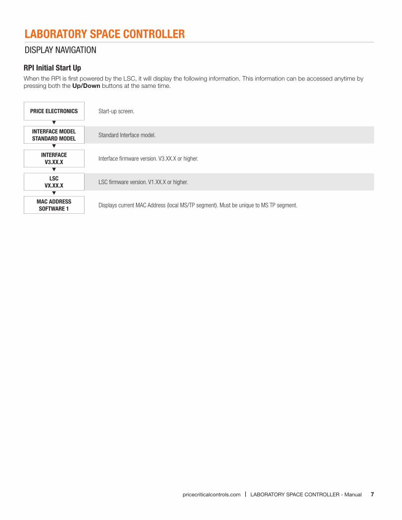
RPI Initial Start UpWhen the RPI is first powered by the LSC, it will display the following information. This information can be accessed anytime by pressing both the Up/Down buttons at the same time.
PRICE ELECTRONICS Start-up screen.
INTERFACE MODEL STANDARD MODEL Standard Interface model.
INTERFACE V3.XX.X Interface firmware version. V3.XX.X or higher.
LSC VX.XX.X LSC firmware version. V1.XX.X or higher.
MAC ADDRESS SOFTWARE 1 Displays current MAC Address (local MS/TP segment). Must be unique to MS TP segment.
LABORATORY SPACE CONTROLLER
8 LABORATORY SPACE CONTROLLER - Manual | pricecriticalcontrols.com
DISPLAY NAVIGATION
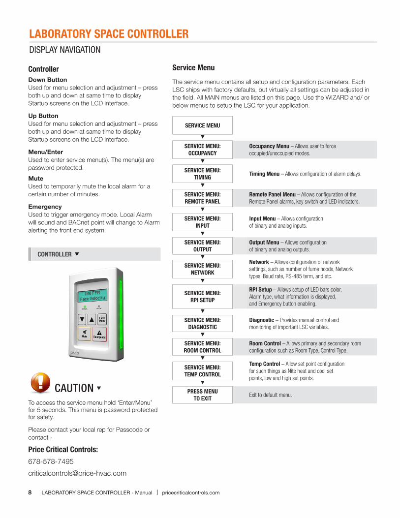
ControllerDown ButtonUsed for menu selection and adjustment – press both up and down at same time to display Startup screens on the LCD interface.
Up Button Used for menu selection and adjustment – press both up and down at same time to display Startup screens on the LCD interface.
Menu/EnterUsed to enter service menu(s). The menu(s) are password protected.
MuteUsed to temporarily mute the local alarm for a certain number of minutes.
EmergencyUsed to trigger emergency mode. Local Alarm will sound and BACnet point will change to Alarm alerting the front end system.
Service Menu
The service menu contains all setup and configuration parameters. Each LSC ships with factory defaults, but virtually all settings can be adjusted in the field. All MAIN menus are listed on this page. Use the WIZARD and/ or below menus to setup the LSC for your application.
CONTROLLER
SERVICE MENU
SERVICE MENU:OCCUPANCY
Occupancy Menu – Allows user to force occupied/unoccupied modes.
SERVICE MENU:TIMING
Timing Menu – Allows configuration of alarm delays.
SERVICE MENU:REMOTE PANEL
Remote Panel Menu – Allows configuration of the Remote Panel alarms, key switch and LED indicators.
SERVICE MENU:INPUT
Input Menu – Allows configuration of binary and analog inputs.
SERVICE MENU:OUTPUT
Output Menu – Allows configuration of binary and analog outputs.
SERVICE MENU:NETWORK
Network – Allows configuration of network settings, such as number of fume hoods, Network types, Baud rate, RS-485 term, and etc.
SERVICE MENU:RPI SETUP
RPI Setup – Allows setup of LED bars color, Alarm type, what information is displayed, and Emergency button enabling.
SERVICE MENU:DIAGNOSTIC
Diagnostic – Provides manual control and monitoring of important LSC variables.
SERVICE MENU:ROOM CONTROL
Room Control – Allows primary and secondary room configuration such as Room Type, Control Type.
SERVICE MENU:TEMP CONTROL
Temp Control – Allow set point configuration for such things as Nite heat and cool set points, low and high set points.
PRESS MENUTO EXIT
Exit to default menu.To access the service menu hold ‘Enter/Menu’ for 5 seconds. This menu is password protected for safety.
Please contact your local rep for Passcode or contact -
Price Critical Controls:
678-578-7495
CAUTION
LABORATORY SPACE CONTROLLER
9pricecriticalcontrols.com | LABORATORY SPACE CONTROLLER - Manual
DISPLAY NAVIGATION
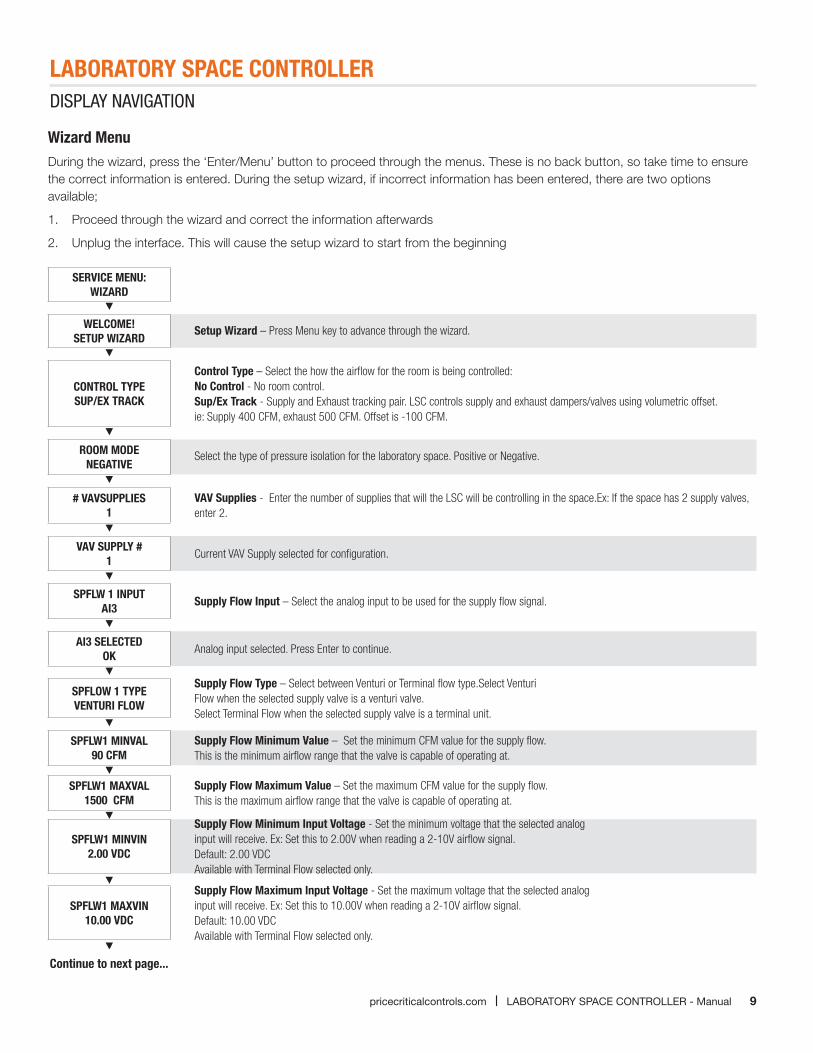
Wizard MenuDuring the wizard, press the ‘Enter/Menu’ button to proceed through the menus. These is no back button, so take time to ensure the correct information is entered. During the setup wizard, if incorrect information has been entered, there are two options available;
1. Proceed through the wizard and correct the information afterwards
2. Unplug the interface. This will cause the setup wizard to start from the beginning
SERVICE MENU: WIZARD
WELCOME! SETUP WIZARD
Setup Wizard – Press Menu key to advance through the wizard.
CONTROL TYPE SUP/EX TRACK
Control Type – Select the how the airflow for the room is being controlled:No Control - No room control.Sup/Ex Track - Supply and Exhaust tracking pair. LSC controls supply and exhaust dampers/valves using volumetric offset. ie: Supply 400 CFM, exhaust 500 CFM. Offset is -100 CFM.
ROOM MODE NEGATIVE
Select the type of pressure isolation for the laboratory space. Positive or Negative.
# VAVSUPPLIES 1
VAV Supplies - Enter the number of supplies that will the LSC will be controlling in the space.Ex: If the space has 2 supply valves, enter 2.
VAV SUPPLY #1
Current VAV Supply selected for configuration.
SPFLW 1 INPUTAI3
Supply Flow Input – Select the analog input to be used for the supply flow signal.
AI3 SELECTEDOK
Analog input selected. Press Enter to continue.
SPFLOW 1 TYPEVENTURI FLOW
Supply Flow Type – Select between Venturi or Terminal flow type.Select Venturi Flow when the selected supply valve is a venturi valve.Select Terminal Flow when the selected supply valve is a terminal unit.
SPFLW1 MINVAL90 CFM
Supply Flow Minimum Value – Set the minimum CFM value for the supply flow.This is the minimum airflow range that the valve is capable of operating at.
SPFLW1 MAXVAL1500 CFM
Supply Flow Maximum Value – Set the maximum CFM value for the supply flow.This is the maximum airflow range that the valve is capable of operating at.
SPFLW1 MINVIN2.00 VDC
Supply Flow Minimum Input Voltage - Set the minimum voltage that the selected analog input will receive. Ex: Set this to 2.00V when reading a 2-10V airflow signal.Default: 2.00 VDCAvailable with Terminal Flow selected only.
SPFLW1 MAXVIN10.00 VDC
Supply Flow Maximum Input Voltage - Set the maximum voltage that the selected analog input will receive. Ex: Set this to 10.00V when reading a 2-10V airflow signal.Default: 10.00 VDCAvailable with Terminal Flow selected only.
Continue to next page...
LABORATORY SPACE CONTROLLER
10 LABORATORY SPACE CONTROLLER - Manual | pricecriticalcontrols.com
DISPLAY NAVIGATION
Wizard Menu Continued
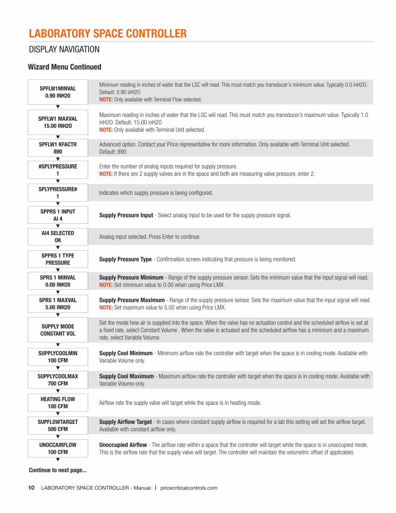
SPFLW1MINVAL0.90 INH20
Minimum reading in inches of water that the LSC will read. This must match you transducer’s minimum value. Typically 0.0 inH2O.Default: 0.90 inH2ONOTE: Only available with Terminal Flow selected.
SPFLW1 MAXVAL15.00 INH2O
Maximum reading in inches of water that the LSC will read. This must match you transducer’s maximum value. Typically 1.0 inH2O. Default: 15.00 inH2ONOTE: Only available with Terminal Unit selected.
SPFLW1 KFACTR890
Advanced option. Contact your Price representative for more information. Only available with Terminal Unit selected. Default: 890
#SPLYPRESSURE1
Enter the number of analog inputs required for supply pressure.NOTE: If there are 2 supply valves are in the space and both are measuring valve pressure, enter 2.
SPLYPRESSURE#1 Indicates which supply pressure is being configured.
SPPRS 1 INPUTAI 4 Supply Pressure Input - Select analog input to be used for the supply pressure signal.
AI4 SELECTEDOK Analog input selected. Press Enter to continue.
SPPRS 1 TYPEPRESSURE Supply Pressure Type - Confirmation screen indicating that pressure is being monitored.
SPRS 1 MINVAL0.00 INH20
Supply Pressure Minimum - Range of the supply pressure sensor. Sets the minimum value that the input signal will read.NOTE: Set minimum value to 0.00 when using Price LMX.
SPRS 1 MAXVAL5.00 INH20
Supply Pressure Maximum - Range of the supply pressure sensor. Sets the maximum value that the input signal will read.NOTE: Set maximum value to 5.00 when using Price LMX.
SUPPLY MODECONSTANT VOL
Set the mode how air is supplied into the space. When the valve has no actuation control and the scheduled airflow is set at a fixed rate, select Constant Volume . When the valve is actuated and the scheduled airflow has a minimum and a maximum rate, select Variable Volume.
SUPPLYCOOLMIN100 CFM
Supply Cool Minimum - Minimum airflow rate the controller with target when the space is in cooling mode. Available with Variable Volume only.
SUPPLYCOOLMAX700 CFM
Supply Cool Maximum - Maximum airflow rate the controller with target when the space is in cooling mode. Available with Variable Volume only.
HEATING FLOW100 CFM Airflow rate the supply valve will target while the space is in heating mode.
SUPFLOWTARGET500 CFM
Supply Airflow Target - In cases where constant supply airflow is required for a lab this setting will set the airflow target. Available with constant airflow only.
UNOCCAIRFLOW100 CFM
Unoccupied Airflow - The airflow rate within a space that the controller will target while the space is in unoccupied mode. This is the airflow rate that the supply valve will target. The controller will maintain the volumetric offset (if applicable).
Continue to next page...
LABORATORY SPACE CONTROLLER
11pricecriticalcontrols.com | LABORATORY SPACE CONTROLLER - Manual
DISPLAY NAVIGATION
Wizard Menu Continued
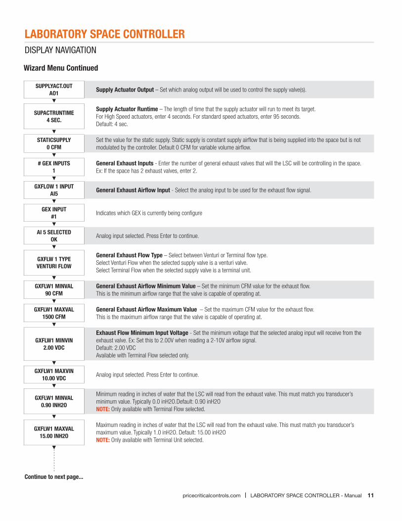
SUPPLYACT.OUTAO1 Supply Actuator Output – Set which analog output will be used to control the supply valve(s).
SUPACTRUNTIME4 SEC.
Supply Actuator Runtime – The length of time that the supply actuator will run to meet its target.For High Speed actuators, enter 4 seconds. For standard speed actuators, enter 95 seconds.Default: 4 sec.
STATICSUPPLY0 CFM
Set the value for the static supply. Static supply is constant supply airflow that is being supplied into the space but is not modulated by the controller. Default 0 CFM for variable volume airflow.
# GEX INPUTS1
General Exhaust Inputs - Enter the number of general exhaust valves that will the LSC will be controlling in the space.Ex: If the space has 2 exhaust valves, enter 2.
GXFLOW 1 INPUTAI5 General Exhaust Airflow Input - Select the analog input to be used for the exhaust flow signal.
GEX INPUT #1 Indicates which GEX is currently being configure
AI 5 SELECTEDOK Analog input selected. Press Enter to continue.
GXFLW 1 TYPEVENTURI FLOW
General Exhaust Flow Type – Select between Venturi or Terminal flow type.Select Venturi Flow when the selected supply valve is a venturi valve.Select Terminal Flow when the selected supply valve is a terminal unit.
GXFLW1 MINVAL90 CFM
General Exhaust Airflow Minimum Value – Set the minimum CFM value for the exhaust flow.This is the minimum airflow range that the valve is capable of operating at.
GXFLW1 MAXVAL1500 CFM
General Exhaust Airflow Maximum Value – Set the maximum CFM value for the exhaust flow.This is the maximum airflow range that the valve is capable of operating at.
GXFLW1 MINVIN2.00 VDC
Exhaust Flow Minimum Input Voltage - Set the minimum voltage that the selected analog input will receive from the exhaust valve. Ex: Set this to 2.00V when reading a 2-10V airflow signal.Default: 2.00 VDCAvailable with Terminal Flow selected only.
GXFLW1 MAXVIN10.00 VDC Analog input selected. Press Enter to continue.
GXFLW1 MINVAL0.90 INH2O
Minimum reading in inches of water that the LSC will read from the exhaust valve. This must match you transducer’s minimum value. Typically 0.0 inH2O.Default: 0.90 inH2ONOTE: Only available with Terminal Flow selected.
GXFLW1 MAXVAL15.00 INH2O
Maximum reading in inches of water that the LSC will read from the exhaust valve. This must match you transducer’s maximum value. Typically 1.0 inH2O. Default: 15.00 inH2ONOTE: Only available with Terminal Unit selected.
Continue to next page...

LABORATORY SPACE CONTROLLER
12 LABORATORY SPACE CONTROLLER - Manual | pricecriticalcontrols.com
DISPLAY NAVIGATION
GXFLW1 KFACTR890
Advanced option. Contact your Price representative for more information. Only available with Terminal Unit selected. Default: 890
#EXHAUSTPRESS1
Enter the number of analog inputs required for exhaust pressure.NOTE: If there are 2 exhaust valves are in the space and both are measuring valve pressure, enter 2.
EXHAUSTPRESS#1 Indicates which exhaust pressure is being configured.
EXPRS1 INPUTAI 6 Exhaust Pressure Input – Select analog input to be used for the exhaust pressure signal.
AI 6 SELECTEDOK Analog input selected. Press Enter to continue.
EXPRS1 TYPEPRESSURE Exhaust Pressure Type – Confirmation screen indicating that pressure is being monitored
EXPRS1 MINVAL0.00 INH2O
Exhaust Pressure Minimum Value - Range of the pressure transducer. Sets the minimum value that the input signal will read. NOTE: Set minimum value to 0.00 when using Price LMX
EXPRS1 MAXVAL5.00 INH2O
Exhaust Pressure Maximum Value - Range of the pressure transducer. Sets the maximum value that the input signal will read. NOTE: Set maximum value to 5.00 when using Price LMX
EXACTUATOROUTA02 Exhaust Actuator Output - Sets the analog output that will drive the exhaust valve(s).
EXACTRUNTIME4 SEC
Exhaust Actuator Runtime - The length of time that the exhaust actuator will run to meets it target. For High Speed actuators, enter 4 seconds. For standard speed actuators, enter 95 seconds. Default: 4 sec.
REHEAT OUTPUTA05
Exhaust Actuator Runtime - The length of time that the exhaust actuator will run to meets it target. For High Speed actuators, enter 4 seconds. For standard speed actuators, enter 95 seconds. Default: 4 sec.
STATICEXHAUST0 CFM
Set the airflow value for the static exhaust. Static exhaust is constant exhaust airflow that is exhausted out of the space and is not modulated by the controller. Default: 0 CFM for variable volume airflow.
CAL VALVEOK Start of valve calibration. There will be a count down from 120 sec to 0 while calibrating.
# FUME HOODS 1 Enter the number of fume hoods (up to 16 MAX) that are going to be required in a lab.
FLOW OFFSET0 CFM
Select the CFM offset value for the fixed offset type. This the volumetric offset that the LSC will target to maintain. Ex: Flow offset = 200 CFM. A negatively pressured room’s total exhaust airflow rate will be 200 CFM more than the total supply airflow rate. A positively pressured room will be the opposite.
ALARM DELAY30 SEC
User set time delay between an alarm condition being detected and an alarm sounding.Default: 30 sec.
Wizard Menu Continued
Continue to next page...
LABORATORY SPACE CONTROLLER
13pricecriticalcontrols.com | LABORATORY SPACE CONTROLLER - Manual
DISPLAY NAVIGATION
Wizard Menu Continued
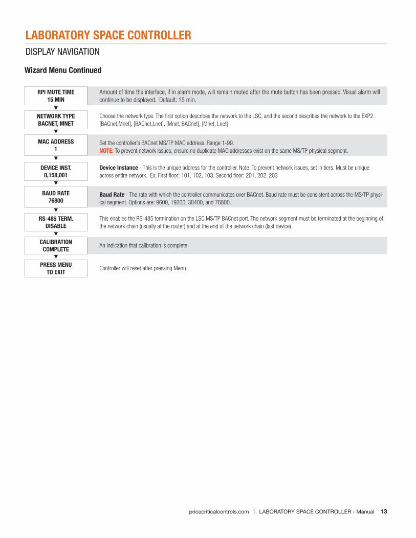
RPI MUTE TIME15 MIN
Amount of time the interface, if in alarm mode, will remain muted after the mute button has been pressed. Visual alarm will continue to be displayed. Default: 15 min.
NETWORK TYPE BACNET, MNET
Choose the network type. The first option describes the network to the LSC, and the second describes the network to the EXP2.[BACnet,Mnet], [BACnet,Lnet], [Mnet, BACnet], [Mnet, Lnet]
MAC ADDRESS 1
Set the controller’s BACnet MS/TP MAC address. Range 1-99. NOTE: To prevent network issues, ensure no duplicate MAC addresses exist on the same MS/TP physical segment.
DEVICE INST. 0,158,001
Device Instance - This is the unique address for the controller. Note: To prevent network issues, set in tiers. Must be unique across entire network. Ex: First floor; 101, 102, 103. Second floor; 201, 202, 203
BAUD RATE 76800
Baud Rate - The rate with which the controller communicates over BACnet. Baud rate must be consistent across the MS/TP physi-cal segment. Options are: 9600, 19200, 38400, and 76800.
RS-485 TERM. DISABLE
This enables the RS-485 termination on the LSC MS/TP BACnet port. The network segment must be terminated at the beginning of the network chain (usually at the router) and at the end of the network chain (last device).
CALIBRATION COMPLETE
An indication that calibration is complete.
PRESS MENU TO EXIT
Controller will reset after pressing Menu.
LABORATORY SPACE CONTROLLER
14 LABORATORY SPACE CONTROLLER - Manual | pricecriticalcontrols.com
DISPLAY NAVIGATION
Timing Menu
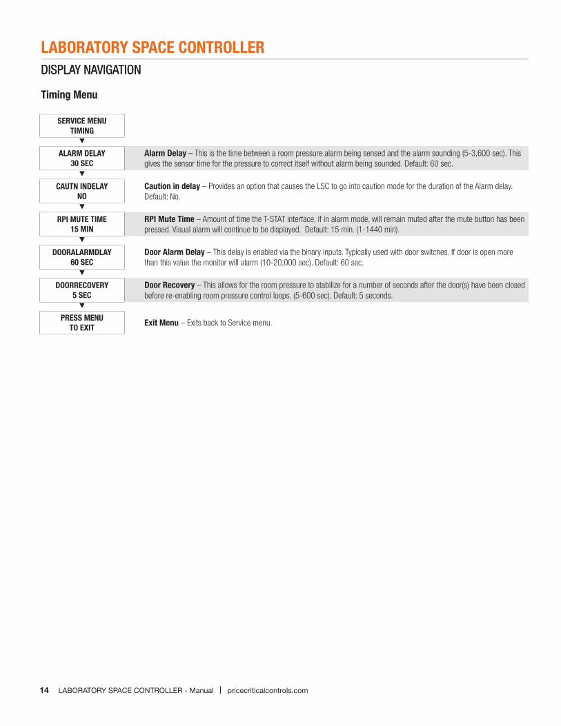
SERVICE MENUTIMING
ALARM DELAY30 SEC
Alarm Delay – This is the time between a room pressure alarm being sensed and the alarm sounding (5-3,600 sec). This gives the sensor time for the pressure to correct itself without alarm being sounded. Default: 60 sec.
CAUTN INDELAYNO
Caution in delay – Provides an option that causes the LSC to go into caution mode for the duration of the Alarm delay. Default: No.
RPI MUTE TIME15 MIN
RPI Mute Time – Amount of time the T-STAT interface, if in alarm mode, will remain muted after the mute button has been pressed. Visual alarm will continue to be displayed. Default: 15 min. (1-1440 min).
DOORALARMDLAY60 SEC
Door Alarm Delay – This delay is enabled via the binary inputs. Typically used with door switches. If door is open more than this value the monitor will alarm (10-20,000 sec). Default: 60 sec.
DOORRECOVERY5 SEC
Door Recovery – This allows for the room pressure to stabilize for a number of seconds after the door(s) have been closed before re-enabling room pressure control loops. (5-600 sec). Default: 5 seconds.
PRESS MENUTO EXIT Exit Menu – Exits back to Service menu.
DISPLAY NAVIGATION
LABORATORY SPACE CONTROLLER
15pricecriticalcontrols.com | LABORATORY SPACE CONTROLLER - Manual
DISPLAY NAVIGATIONDISPLAY NAVIGATION
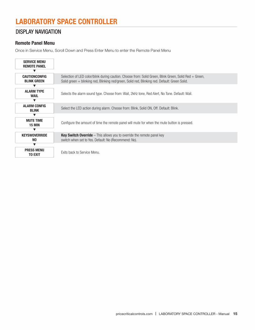
Remote Panel MenuOnce in Service Menu, Scroll Down and Press Enter Menu to enter the Remote Panel Menu
SERVICE MENUREMOTE PANEL
CAUTIONCONFIGBLINK GREEN
Selection of LED color/blink during caution. Choose from: Solid Green, Blink Green, Solid Red + Green, Solid green + blinking red, Blinking red/green, Solid red, Blinking red. Default: Green Solid.
ALARM TYPEWAIL Selects the alarm sound type. Choose from: Wail, 2kHz tone, Red Alert, No Tone. Default: Wail.
ALARM CONFIGBLINK Select the LED action during alarm. Choose from: Blink, Solid ON, Off. Default: Blink.
MUTE TIME15 MIN Configure the amount of time the remote panel will mute for when the mute button is pressed.
KEYSWOVERRIDENO
Key Switch Override – This allows you to override the remote panel key switch when set to Yes. Default: No (Recommend: No).
PRESS MENUTO EXIT Exits back to Service Menu.
LABORATORY SPACE CONTROLLER
16 LABORATORY SPACE CONTROLLER - Manual | pricecriticalcontrols.com
DISPLAY NAVIGATION
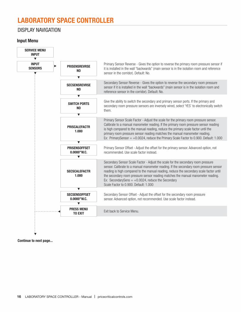
SERVICE MENUINPUT
INPUTSENSORS PRISENSREVRSE
NO
Primary Sensor Reverse - Gives the option to reverse the primary room pressure sensor if it is installed in the wall “backwards” (main sensor is in the isolation room and reference sensor in the corridor). Default: No.
SECSENSREVRSENO
Secondary Sensor Reverse - Gives the option to reverse the secondary room pressure sensor if it is installed in the wall “backwards” (main sensor is in the isolation room and reference sensor in the corridor). Default: No.
SWITCH PORTSNO
Give the ability to switch the secondary and primary sensor ports. If the primary and secondary room pressure sensors are inversely wired, select ‘YES’ to electronically switch them.
PRISCALEFACTR1.000
Primary Sensor Scale Factor - Adjust the scale for the primary room pressure sensor. Calibrate to a manual manometer reading. If the primary room pressure sensor reading is high compared to the manual reading, reduce the primary scale factor until the primary room pressure sensor reading matches the manual manometer reading. Ex: PrimarySensor = +0.0024, reduce the Primary Scale Factor to 0.900. Default: 1.000
PRISENSOFFSET0.0000”W.C.
Primary Sensor Offset - Adjust the offset for the primary sensor. Advanced option, not recommended. Use scale factor instead.
SECSCALEFACTR1.000
Secondary Sensor Scale Factor - Adjust the scale for the secondary room pressure sensor. Calibrate to a manual manometer reading. If the secondary room pressure sensor reading is high compared to the manual reading, reduce the secondary scale factor until the secondary room pressure sensor reading matches the manual manometer reading. Ex: SecondarySens = +0.0024, reduce the Secondary Scale Factor to 0.900. Default: 1.000
SECSENSOFFSET0.0000”W.C.
Secondary Sensor Offset - Adjust the offset for the secondary room pressure sensor. Advanced option, not recommended. Use scale factor instead.
PRESS MENUTO EXIT Exit back to Service Menu.
Input Menu
Continue to next page...
17
LABORATORY SPACE CONTROLLERDISPLAY NAVIGATION
pricecriticalcontrols.com | LABORATORY SPACE CONTROLLER - Manual
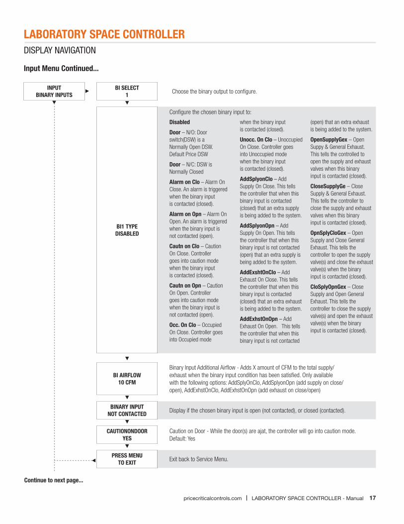
INPUTBINARY INPUTS
BI SELECT1 Choose the binary output to configure.
BI1 TYPEDISABLED
Configure the chosen binary input to:
Disabled
Door – N/O: Door switch(DSW) is a Normally Open DSW. Default Price DSW
Door – N/C: DSW is Normally Closed
Alarm on Clo – Alarm On Close. An alarm is triggered when the binary input is contacted (closed).
Alarm on Opn – Alarm On Open. An alarm is triggered when the binary input is not contacted (open).
Cautn on Clo – Caution On Close. Controller goes into caution mode when the binary input is contacted (closed).
Cautn on Opn – Caution On Open. Controller goes into caution mode when the binary input is not contacted (open).
Occ. On Clo – Occupied On Close. Controller goes into Occupied mode
when the binary input is contacted (closed).
Unocc. On Clo – Unoccupied On Close. Controller goes into Unoccupied mode when the binary input is contacted (closed).
AddSplyonClo – Add Supply On Close. This tells the controller that when this binary input is contacted (closed) that an extra supply is being added to the system.
AddSplyonOpn – Add Supply On Open. This tells the controller that when this binary input is not contacted (open) that an extra supply is being added to the system.
AddExshtOnClo – Add Exhaust On Close. This tells the controller that when this binary input is contacted (closed) that an extra exhaust is being added to the system.
AddExhstOnOpn – Add Exhaust On Open. This tells the controller that when this binary input is not contacted
(open) that an extra exhaust is being added to the system.
OpenSupplyGex – Open Suppy & General Exhaust. This tells the controlled to open the supply and exhaust valves when this binary input is contacted (closed).
CloseSupplyGe – Close Supply & General Exhaust. This tells the controller to close the supply and exhaust valves when this binary input is contacted (closed).
OpnSplyCloGex – Open Supply and Close General Exhaust. This tells the controller to open the supply valve(s) and close the exhaust valve(s) when the binary input is contacted (closed).
CloSplyOpnGex – Close Supply and Open General Exhaust. This tells the controller to close the supply valve(s) and open the exhaust valve(s) when the binary input is contacted (closed).
BI AIRFLOW10 CFM
Binary Input Additional Airflow - Adds X amount of CFM to the total supply/exhaust when the binary input condition has been satisfied. Only available with the following options: AddSplyOnClo, AddSplyonOpn (add supply on close/open), AddExhstOnClo, AddExhstOnOpn (add exhaust on close/open)
BINARY INPUTNOT CONTACTED Display if the chosen binary input is open (not contacted), or closed (contacted).
CAUTIONONDOORYES
Caution on Door - While the door(s) are ajat, the controller will go into caution mode.Default: Yes
PRESS MENUTO EXIT Exit back to Service Menu.
Input Menu Continued...
Continue to next page...
LABORATORY SPACE CONTROLLER
18 LABORATORY SPACE CONTROLLER - Manual | pricecriticalcontrols.com
DISPLAY NAVIGATION
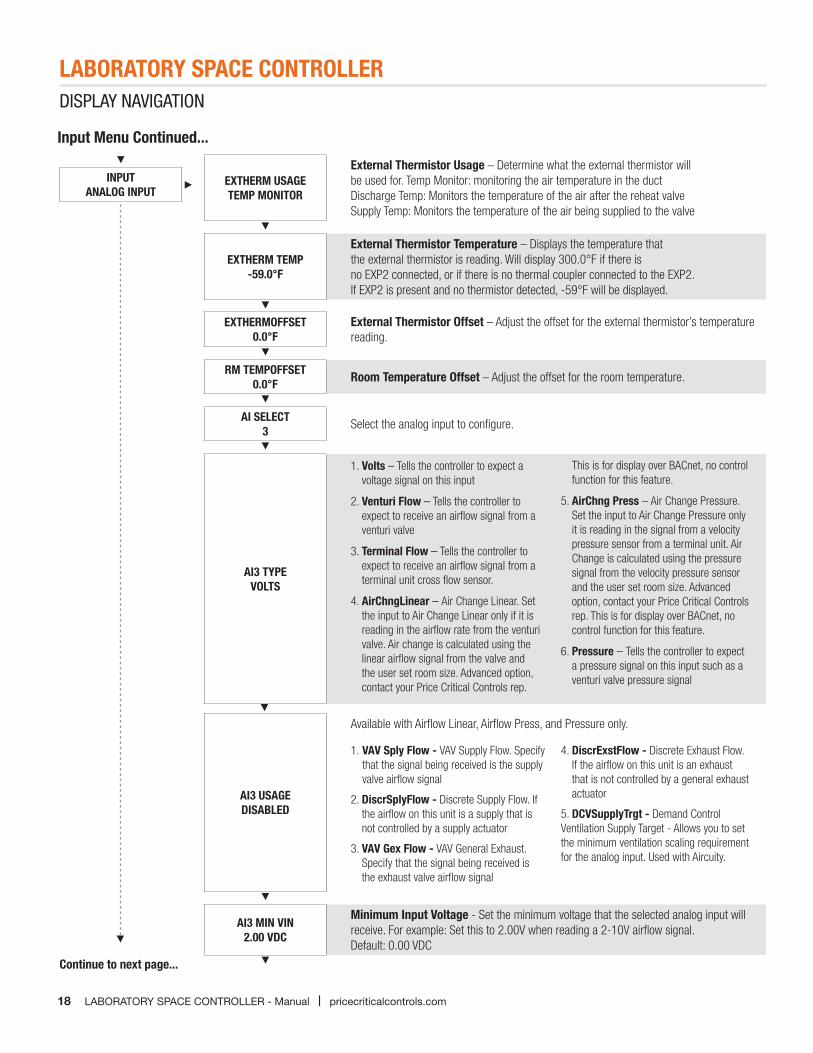
Input Menu Continued...
EXTHERM USAGETEMP MONITOR
External Thermistor Usage – Determine what the external thermistor will be used for. Temp Monitor: monitoring the air temperature in the ductDischarge Temp: Monitors the temperature of the air after the reheat valve Supply Temp: Monitors the temperature of the air being supplied to the valve
EXTHERM TEMP-59.0°F
External Thermistor Temperature – Displays the temperature that the external thermistor is reading. Will display 300.0°F if there isno EXP2 connected, or if there is no thermal coupler connected to the EXP2. If EXP2 is present and no thermistor detected, -59°F will be displayed.
EXTHERMOFFSET0.0°F
External Thermistor Offset – Adjust the offset for the external thermistor’s temperature reading.
RM TEMPOFFSET0.0°F Room Temperature Offset – Adjust the offset for the room temperature.
AI SELECT3 Select the analog input to configure.
AI3 TYPEVOLTS
1. Volts – Tells the controller to expect a voltage signal on this input
2. Venturi Flow – Tells the controller to expect to receive an airflow signal from a venturi valve
3. Terminal Flow – Tells the controller to expect to receive an airflow signal from a terminal unit cross flow sensor.
4. AirChngLinear – Air Change Linear. Set the input to Air Change Linear only if it is reading in the airflow rate from the venturi valve. Air change is calculated using the linear airflow signal from the valve and the user set room size. Advanced option, contact your Price Critical Controls rep.
This is for display over BACnet, no control function for this feature.
5. AirChng Press – Air Change Pressure. Set the input to Air Change Pressure only it is reading in the signal from a velocity pressure sensor from a terminal unit. Air Change is calculated using the pressure signal from the velocity pressure sensor and the user set room size. Advanced option, contact your Price Critical Controls rep. This is for display over BACnet, no control function for this feature.
6. Pressure – Tells the controller to expect a pressure signal on this input such as a venturi valve pressure signal
AI3 USAGEDISABLED
Available with Airflow Linear, Airflow Press, and Pressure only.
1. VAV Sply Flow - VAV Supply Flow. Specify that the signal being received is the supply valve airflow signal
2. DiscrSplyFlow - Discrete Supply Flow. If the airflow on this unit is a supply that is not controlled by a supply actuator
3. VAV Gex Flow - VAV General Exhaust. Specify that the signal being received is the exhaust valve airflow signal
4. DiscrExstFlow - Discrete Exhaust Flow. If the airflow on this unit is an exhaust that is not controlled by a general exhaust actuator
5. DCVSupplyTrgt - Demand Control Ventilation Supply Target - Allows you to set the minimum ventilation scaling requirement for the analog input. Used with Aircuity.
AI3 MIN VIN2.00 VDC
Minimum Input Voltage - Set the minimum voltage that the selected analog input will receive. For example: Set this to 2.00V when reading a 2-10V airflow signal. Default: 0.00 VDC
INPUTANALOG INPUT
Continue to next page...
LABORATORY SPACE CONTROLLER
19pricecriticalcontrols.com | LABORATORY SPACE CONTROLLER - Manual
DISPLAY NAVIGATION
Input Menu Continued...
PRESS MENUTO EXIT
AI3 MAX VIN10.00 VDC
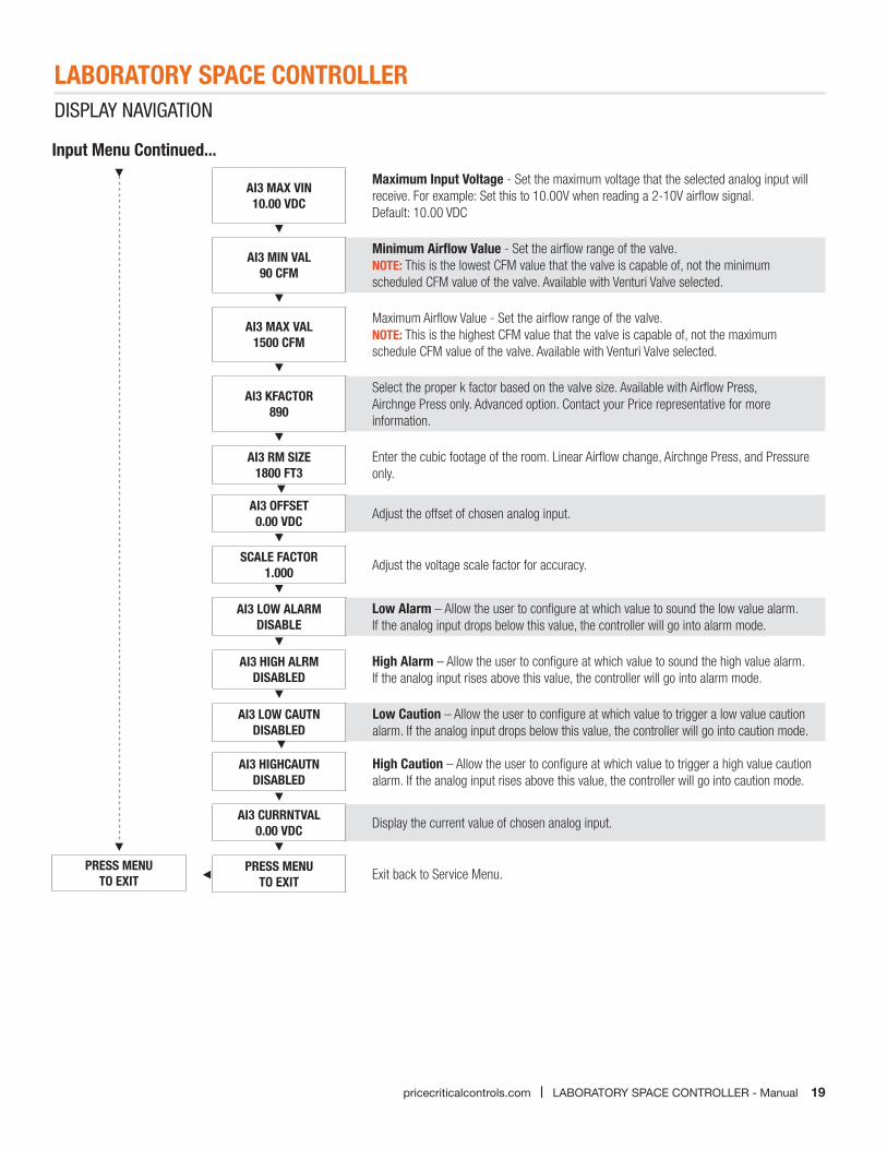
Maximum Input Voltage - Set the maximum voltage that the selected analog input will receive. For example: Set this to 10.00V when reading a 2-10V airflow signal. Default: 10.00 VDC
AI3 MIN VAL90 CFM
Minimum Airflow Value - Set the airflow range of the valve.NOTE: This is the lowest CFM value that the valve is capable of, not the minimum scheduled CFM value of the valve. Available with Venturi Valve selected.
AI3 MAX VAL1500 CFM
Maximum Airflow Value - Set the airflow range of the valve. NOTE: This is the highest CFM value that the valve is capable of, not the maximum schedule CFM value of the valve. Available with Venturi Valve selected.
AI3 KFACTOR890
Select the proper k factor based on the valve size. Available with Airflow Press,Airchnge Press only. Advanced option. Contact your Price representative for more information.
AI3 RM SIZE1800 FT3
Enter the cubic footage of the room. Linear Airflow change, Airchnge Press, and Pressureonly.
AI3 OFFSET0.00 VDC Adjust the offset of chosen analog input.
SCALE FACTOR1.000 Adjust the voltage scale factor for accuracy.
AI3 LOW ALARMDISABLE
Low Alarm – Allow the user to configure at which value to sound the low value alarm. If the analog input drops below this value, the controller will go into alarm mode.
AI3 HIGH ALRMDISABLED
High Alarm – Allow the user to configure at which value to sound the high value alarm. If the analog input rises above this value, the controller will go into alarm mode.
AI3 LOW CAUTNDISABLED
Low Caution – Allow the user to configure at which value to trigger a low value caution alarm. If the analog input drops below this value, the controller will go into caution mode.
AI3 HIGHCAUTNDISABLED
High Caution – Allow the user to configure at which value to trigger a high value caution alarm. If the analog input rises above this value, the controller will go into caution mode.
AI3 CURRNTVAL0.00 VDC Display the current value of chosen analog input.
PRESS MENUTO EXIT Exit back to Service Menu.
LABORATORY SPACE CONTROLLER
20 LABORATORY SPACE CONTROLLER - Manual | pricecriticalcontrols.com
DISPLAY NAVIGATION
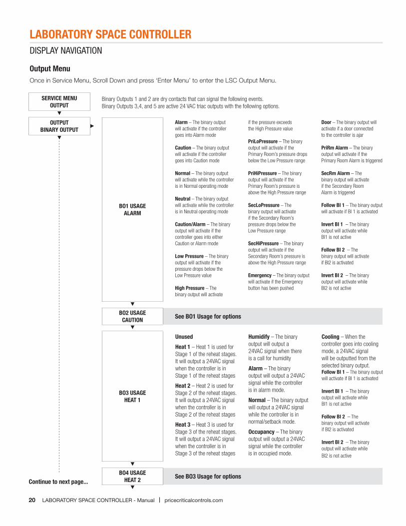
Output MenuOnce in Service Menu, Scroll Down and press ‘Enter Menu’ to enter the LSC Output Menu.
SERVICE MENUOUTPUT
OUTPUTBINARY OUTPUT
BO1 USAGEALARM
Alarm – The binary output will activate if the controller goes into Alarm mode Caution – The binary output will activate if the controller goes into Caution mode Normal – The binary output will activate while the controller is in Normal operating mode Neutral – The binary output will activate while the controller is in Neutral operating mode Caution/Alarm – The binary output will activate if the controller goes into either Caution or Alarm mode Low Pressure – The binary output will activate if the pressure drops below the Low Pressure value High Pressure – The binary output will activate
if the pressure exceeds the High Pressure value PriLoPressure – The binary output will activate if the Primary Room’s pressure drops below the Low Pressure range PriHiPressure – The binary output will activate if the Primary Room’s pressure is above the High Pressure range SecLoPressure – The binary output will activate if the Secondary Room’s pressure drops below the Low Pressure range SecHiPressure – The binary output will activate if the Secondary Room’s pressure is above the High Pressure range Emergency – The binary output will activate if the Emergency button has been pushed
Door – The binary output will activate if a door connected to the controller is ajar PriRm Alarm – The binary output will activate if the Primary Room Alarm is triggered SecRm Alarm – The binary output will activate if the Secondary Room Alarm is triggered Follow BI 1 – The binary output will activate if BI 1 is activated Invert BI 1 – The binary output will activate while BI1 is not active Follow BI 2 – The binary output will activate if BI2 is activated Invert BI 2 – The binary output will activate while BI2 is not active
BO2 USAGECAUTION See BO1 Usage for options
BO3 USAGEHEAT 1
BO4 USAGEHEAT 2 See BO3 Usage for options
Binary Outputs 1 and 2 are dry contacts that can signal the following events.Binary Outputs 3,4, and 5 are active 24 VAC triac outputs with the following options.
Unused
Heat 1 – Heat 1 is used for Stage 1 of the reheat stages. It will output a 24VAC signal when the controller is in Stage 1 of the reheat stages
Heat 2 – Heat 2 is used for Stage 2 of the reheat stages. It will output a 24VAC signal when the controller is in Stage 2 of the reheat stages
Heat 3 – Heat 3 is used for Stage 3 of the reheat stages. It will output a 24VAC signal when the controller is in Stage 3 of the reheat stages
Humidify – The binary output will output a 24VAC signal when there is a call for humidity
Alarm – The binary output will output a 24VAC signal while the controller is in alarm mode.
Normal – The binary output will output a 24VAC signal while the controller is in normal/setback mode.
Occupancy – The binary output will output a 24VAC signal while the controller is in occupied mode.
Cooling – When the controller goes into cooling mode, a 24VAC signal will be outputted from the selected binary output.Follow BI 1 – The binary output will activate if BI 1 is activated Invert BI 1 – The binary output will activate while BI1 is not active Follow BI 2 – The binary output will activate if BI2 is activated Invert BI 2 – The binary output will activate while BI2 is not active
Continue to next page...
LABORATORY SPACE CONTROLLER
21pricecriticalcontrols.com | LABORATORY SPACE CONTROLLER - Manual
DISPLAY NAVIGATION
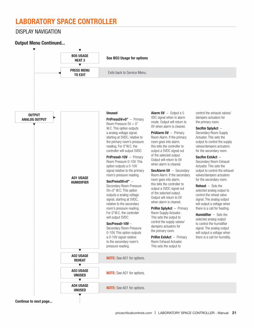
Output Menu Continued...
AO1 USAGEHUMIDIFIER
Unused
PriPress5V=0” – Primary Room Pressure 5V = 0” W.C. This option outputs a analog voltage signal, starting at 5VDC, relative to the primary room’s pressure reading. For 0”W.C. the controller will output 5VDC
PriPress0-10V – Primary Room Pressure 0-10V. This option outputs a 0-10V signal relative to the primary room’s pressure reading.
SecPress5V=0” – Secondary Room Pressure 5V=0” W.C. This option outputs a analog voltage signal, starting at 5VDC, relative to the secondary room’s pressure reading. For 0”W.C. the controller will output 5VDC
SecPress0-10V – Secondary Room Pressure 0-10V. This option outputs a 0-10V signal relative to the secondary room’s pressure reading.
Alarm 5V – Output a 5 VDC signal when in alarm mode. Output will return to 0V when alarm is cleared.
PriAlarm 5V – Primary Room Alarm. If the primary room goes into alarm, this tells the controller to output a 5VDC signal out of the selected output. Output will return to 0V when alarm is cleared.
SecAlarm 5V – Secondary Room Alarm. If the secondary room goes into alarm, this tells the controller to output a 5VDC signal out of the selected output. Output will return to 0V when alarm is cleared.
PriRm SplyAct – Primary Room Supply Actuator. This sets the output to control the supply valves/dampers actuators for the primary room.
PriRm ExhAct – Primary Room Exhaust Actuator. This sets the output to
control the exhaust valves/dampers actuators for the primary room.
SecRm SplyAct – Secondary Room Supply Actuator. This sets the output to control the supply valves/dampers actuators for the secondary room.
SecRm ExhAct – Secondary Room Exhaust Actuator. This sets the output to control the exhaust valves/dampers actuators for the secondary room.
Reheat – Sets the selected analog output to control the reheat valve signal. The analog output will output a voltage when there is a call for heating.
Humidifier – Sets the selected analog output to control the humidifier signal. The analog output will output a voltage when there is a call for humidity.
AO2 USAGEREHEAT NOTE: See A01 for options.
AO3 USAGEUNUSED NOTE: See A01 for options.
AO4 USAGEUNUSED NOTE: See A01 for options.
OUTPUTANALOG OUTPUT
BO5 USAGEHEAT 3 See BO3 Usage for options
PRESS MENUTO EXIT Exits back to Service Menu.
Continue to next page...
22
LABORATORY SPACE CONTROLLERDISPLAY NAVIGATION
LABORATORY SPACE CONTROLLER - Manual | pricecriticalcontrols.com
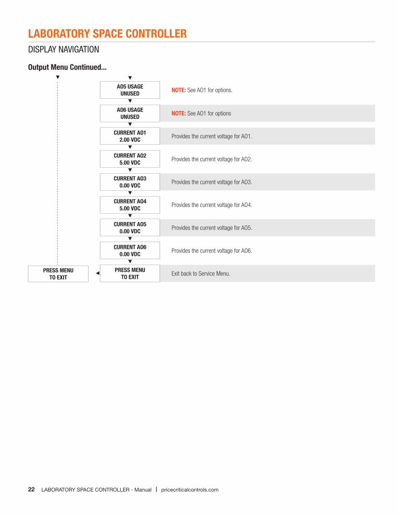
Output Menu Continued...
AO5 USAGEUNUSED NOTE: See AO1 for options.
AO6 USAGEUNUSED NOTE: See AO1 for options
CURRENT AO12.00 VDC Provides the current voltage for AO1.
CURRENT AO25.00 VDC Provides the current voltage for AO2.
CURRENT AO30.00 VDC Provides the current voltage for AO3.
CURRENT AO45.00 VDC Provides the current voltage for AO4.
CURRENT AO50.00 VDC Provides the current voltage for AO5.
CURRENT AO60.00 VDC Provides the current voltage for AO6.
PRESS MENUTO EXIT Exit back to Service Menu.PRESS MENU
TO EXIT
LABORATORY SPACE CONTROLLER
23pricecriticalcontrols.com | LABORATORY SPACE CONTROLLER - Manual
DISPLAY NAVIGATION
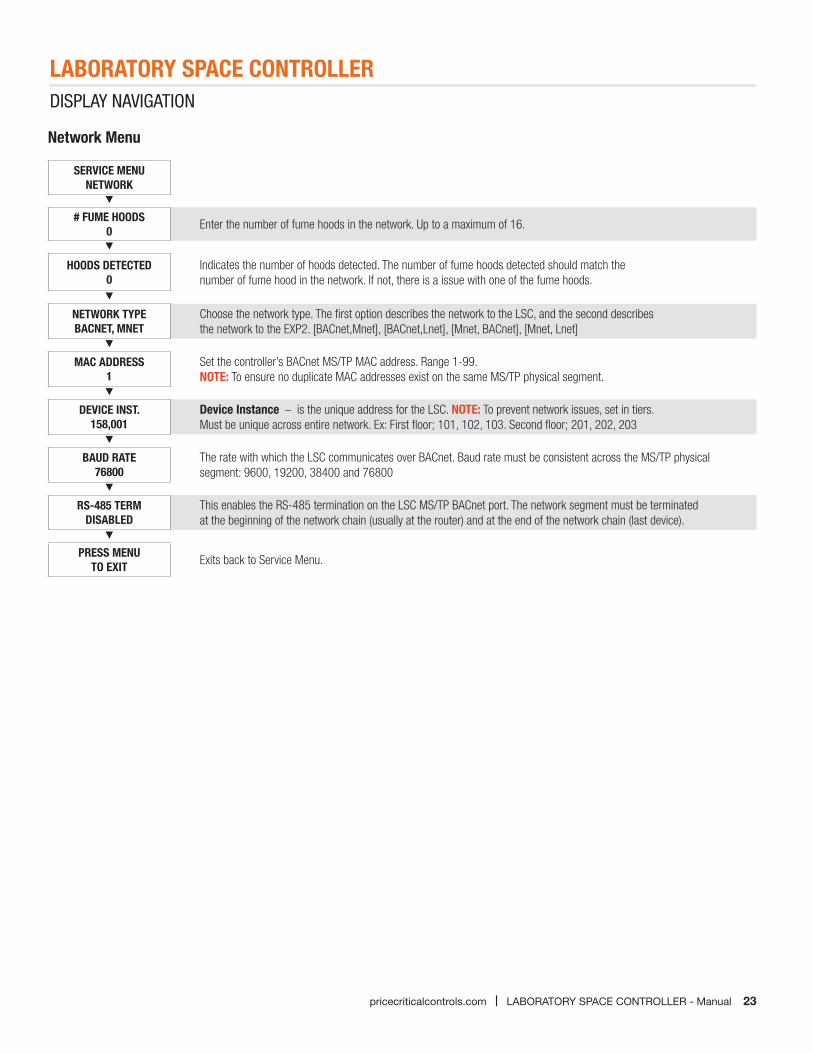
Network Menu
SERVICE MENUNETWORK
# FUME HOODS 0 Enter the number of fume hoods in the network. Up to a maximum of 16.
HOODS DETECTED0
Indicates the number of hoods detected. The number of fume hoods detected should match the number of fume hood in the network. If not, there is a issue with one of the fume hoods.
NETWORK TYPEBACNET, MNET
Choose the network type. The first option describes the network to the LSC, and the second describes the network to the EXP2. [BACnet,Mnet], [BACnet,Lnet], [Mnet, BACnet], [Mnet, Lnet]
MAC ADDRESS1
Set the controller’s BACnet MS/TP MAC address. Range 1-99. NOTE: To ensure no duplicate MAC addresses exist on the same MS/TP physical segment.
DEVICE INST.158,001
Device Instance – is the unique address for the LSC. NOTE: To prevent network issues, set in tiers. Must be unique across entire network. Ex: First floor; 101, 102, 103. Second floor; 201, 202, 203
BAUD RATE76800
The rate with which the LSC communicates over BACnet. Baud rate must be consistent across the MS/TP physical segment: 9600, 19200, 38400 and 76800
RS-485 TERMDISABLED
This enables the RS-485 termination on the LSC MS/TP BACnet port. The network segment must be terminated at the beginning of the network chain (usually at the router) and at the end of the network chain (last device).
PRESS MENUTO EXIT Exits back to Service Menu.
LABORATORY SPACE CONTROLLER
24 LABORATORY SPACE CONTROLLER - Manual | pricecriticalcontrols.com
DISPLAY NAVIGATION
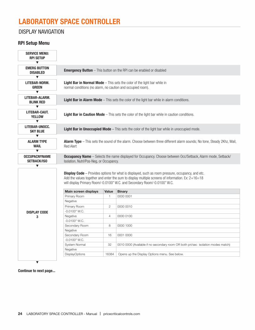
RPI Setup Menu
SERVICE MENU:RPI SETUP
EMERG BUTTONDISABLED Emergency Button – This button on the RPI can be enabled or disabled
LITEBAR-NORM.GREEN
Light Bar in Normal Mode – This sets the color of the light bar while in normal conditions (no alarm, no caution and occupied room).
LITEBAR-ALARM.BLINK RED Light Bar in Alarm Mode – This sets the color of the light bar while in alarm conditions.
LITEBAR-CAUT.YELLOW Light Bar in Caution Mode – This sets the color of the light bar while in caution conditions.
LITEBAR-UNOCC.SKY BLUE Light Bar in Unoccupied Mode – This sets the color of the light bar while in unoccupied mode.
ALARM TYPEWAIL
Alarm Type – This sets the sound of the alarm. Choose between three different alarm sounds; No tone, Steady 2Khz, Wail, Red Alert
OCCUPACNYNAMESETBACK/ISO
Occupancy Name – Selects the name displayed for Occupancy. Choose between Occ/Setback, Alarm mode, Setback/Isolation, Nutrl/Pos-Neg, or Occupancy.
DISPLAY CODE3
Display Code – Provides options for what is displayed, such as room pressure, occupancy, and etc.Add the values together and enter the sum to display multiple screens of information. Ex: 2+16=18 will display Primary Room/-0.0100” W.C. and Secondary Room/-0.0100” W.C.
Main screen displays Value BinaryPrimary Room 1 0000 0001
Negative
Primary Room 2 0000 0010
-0.0100" W.C.
Negative 4 0000 0100
-0.0100" W.C.
Secondary Room 8 0000 1000
Negative
Secondary Room 16 0001 0000
-0.0100" W.C.
System Normal 32 0010 0000 (Available if no secondary room OR both pri/sec isolation modes match)
Negative
DisplayOptions 16384 Opens up the Display Options menu. See below.
Continue to next page...
LABORATORY SPACE CONTROLLER
25pricecriticalcontrols.com | LABORATORY SPACE CONTROLLER - Manual
DISPLAY NAVIGATION
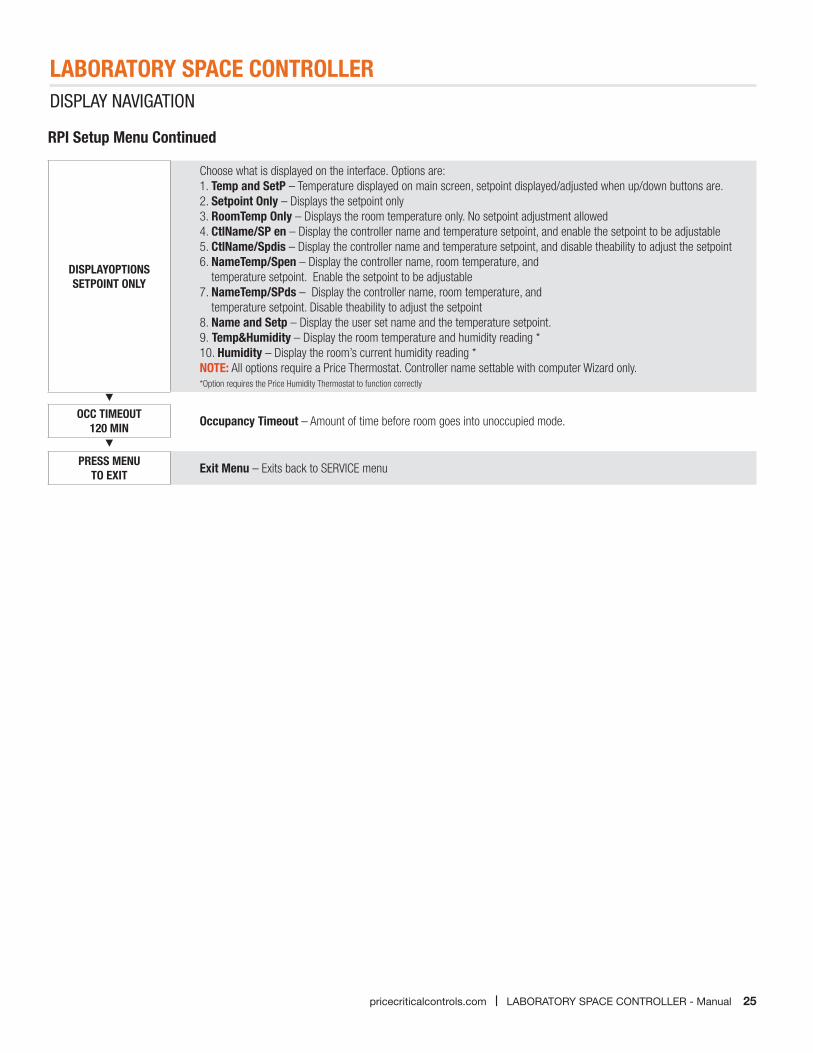
DISPLAYOPTIONS SETPOINT ONLY
Choose what is displayed on the interface. Options are:1. Temp and SetP – Temperature displayed on main screen, setpoint displayed/adjusted when up/down buttons are.2. Setpoint Only – Displays the setpoint only3. RoomTemp Only – Displays the room temperature only. No setpoint adjustment allowed4. CtlName/SP en – Display the controller name and temperature setpoint, and enable the setpoint to be adjustable5. CtlName/Spdis – Display the controller name and temperature setpoint, and disable theability to adjust the setpoint6. NameTemp/Spen – Display the controller name, room temperature, and
temperature setpoint. Enable the setpoint to be adjustable7. NameTemp/SPds – Display the controller name, room temperature, and
temperature setpoint. Disable theability to adjust the setpoint8. Name and Setp – Display the user set name and the temperature setpoint.9. Temp&Humidity – Display the room temperature and humidity reading *10. Humidity – Display the room’s current humidity reading *NOTE: All options require a Price Thermostat. Controller name settable with computer Wizard only.*Option requires the Price Humidity Thermostat to function correctly
OCC TIMEOUT120 MIN Occupancy Timeout – Amount of time before room goes into unoccupied mode.
PRESS MENUTO EXIT Exit Menu – Exits back to SERVICE menu
RPI Setup Menu Continued
LABORATORY SPACE CONTROLLER
26 LABORATORY SPACE CONTROLLER - Manual | pricecriticalcontrols.com
DISPLAY NAVIGATION
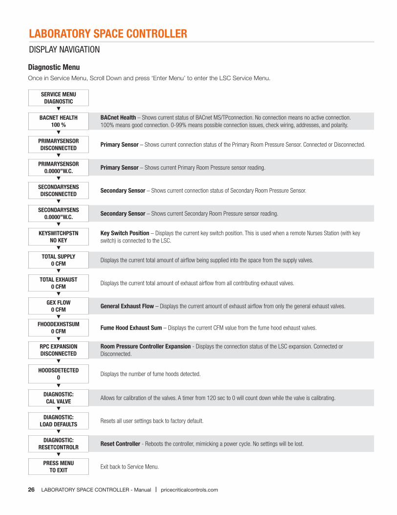
Diagnostic MenuOnce in Service Menu, Scroll Down and press ‘Enter Menu’ to enter the LSC Service Menu.
SERVICE MENUDIAGNOSTIC
BACNET HEALTH100 %
BACnet Health – Shows current status of BACnet MS/TPconnection. No connection means no active connection. 100% means good connection. 0-99% means possible connection issues, check wiring, addresses, and polarity.
PRIMARYSENSORDISCONNECTED Primary Sensor – Shows current connection status of the Primary Room Pressure Sensor. Connected or Disconnected.
PRIMARYSENSOR0.0000”W.C. Primary Sensor – Shows current Primary Room Pressure sensor reading.
SECONDARYSENSDISCONNECTED Secondary Sensor – Shows current connection status of Secondary Room Pressure Sensor.
SECONDARYSENS0.0000”W.C. Secondary Sensor – Shows current Secondary Room Pressure sensor reading.
KEYSWITCHPSTNNO KEY
Key Switch Position – Displays the current key switch position. This is used when a remote Nurses Station (with key switch) is connected to the LSC.
TOTAL SUPPLY0 CFM Displays the current total amount of airflow being supplied into the space from the supply valves.
TOTAL EXHAUST0 CFM Displays the current total amount of exhaust airflow from all contributing exhaust valves.
GEX FLOW0 CFM General Exhaust Flow – Displays the current amount of exhaust airflow from only the general exhaust valves.
FHOODEXHSTSUM0 CFM Fume Hood Exhaust Sum – Displays the current CFM value from the fume hood exhaust valves.
RPC EXPANSIONDISCONNECTED
Room Pressure Controller Expansion - Displays the connection status of the LSC expansion. Connected or Disconnected.
HOODSDETECTED0 Displays the number of fume hoods detected.
DIAGNOSTIC:CAL VALVE Allows for calibration of the valves. A timer from 120 sec to 0 will count down while the valve is calibrating.
DIAGNOSTIC:LOAD DEFAULTS Resets all user settings back to factory default.
DIAGNOSTIC:RESETCONTROLR Reset Controller - Reboots the controller, mimicking a power cycle. No settings will be lost.
PRESS MENUTO EXIT Exit back to Service Menu.
LABORATORY SPACE CONTROLLER
27pricecriticalcontrols.com | LABORATORY SPACE CONTROLLER - Manual
DISPLAY NAVIGATION
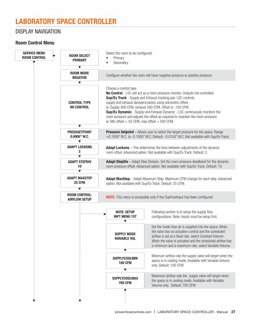
Room Control Menu
SERVICE MENUROOM CONTROL ROOM SELECT
PRIMARY
Select the room to be configured.• Primary• Secondary
ROOM MODENEGATIVE Configure whether the room will have negative pressure or positive pressure.
CONTROL TYPENO CONTROL
Choose a control type:No Control - LSC will act as a room pressure monitor. Outputs not controlled.Sup/Ex Track - Supply and Exhaust tracking pair. LSC controls supply and exhaust dampers/valves using volumetric offset. ie: Supply 400 CFM, exhaust 500 CFM. Offset is -100 CFM.Sup/Ex Dynamic - Supply and Exhaust Dynamic - LSC continuously monitors the room pressure and adjusts the offset as required to maintain the room pressure. ie: Min offset = 50 CFM, max offset = 500 CFM.
PRESSSETPOINT0.0000” W.C.
Pressure Setpoint – Allows user to select the target pressure for the space. Range +0.1000” W.C. to -0.1000” W.C. Default: -0.0150” W.C. Not available with Sup/Ex Track.
ADAPT LOCKONS2
Adapt Lockons – This determines the time between adjustments of the dynamic room offset. Advanced option. Not available with Sup/Ex Track. Default: 2.
ADAPT STEPDIV10
Adapt StepDiv – Adapt Step Division. Set the room pressure deadband for the dynamic room pressure offset. Advanced option. Not available with Sup/Ex Track. Default: 10.
ADAPT MAXSTEP25 CFM
Adapt MaxStep – Adapt Maximum Step. Maximum CFM change for each step. Advanced option. Not available with Sup/Ex Track. Default: 25 CFM.
ROOM CONTROL:AIRFLOW SETUP NOTE: This menu is accessible only if the SupFlowInput has been configured
NOTE: SETUP INPT MENU 1ST
Following section is to setup the supply flow configurations. Note: Inputs must be setup first.
SUPPLY MODEVARIABLE VOL
Set the mode how air is supplied into the space. When the valve has no actuation control and the scheduled airflow is set at a fixed rate, select Constant Volume . When the valve is actuated and the scheduled airflow has a minimum and a maximum rate, select Variable Volume.
SUPPLYCOOLMIN100 CFM
Minimum airflow rate the supply valve will target when the space is in cooling mode. Available with Variable Volume only. Default: 100 CFM
SUPPLYCOOLMAX700 CFM
Maximum airflow rate the supply valve will target when the space is in cooling mode. Available with Variable Volume only. Default: 700 CFM
LABORATORY SPACE CONTROLLER
28 LABORATORY SPACE CONTROLLER - Manual | pricecriticalcontrols.com
DISPLAY NAVIGATIONDISPLAY NAVIGATION
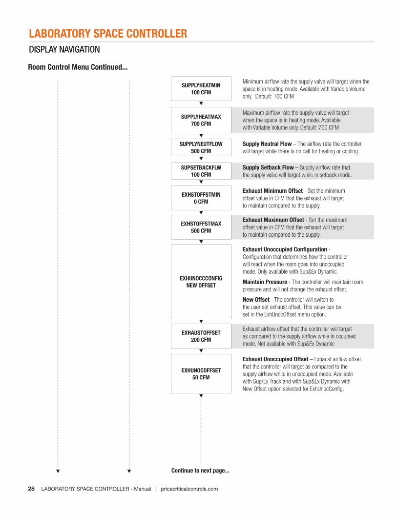
Room Control Menu Continued...
SUPPLYHEATMIN100 CFM
Minimum airflow rate the supply valve will target when the space is in heating mode. Available with Variable Volume only. Default: 100 CFM
SUPPLYHEATMAX700 CFM
Maximum airflow rate the supply valve will target when the space is in heating mode. Available with Variable Volume only. Default: 700 CFM
SUPPLYNEUTFLOW500 CFM
Supply Neutral Flow – The airflow rate the controller will target while there is no call for heating or cooling.
SUPSETBACKFLW100 CFM
Supply Setback Flow – Supply airflow rate that the supply valve will target while in setback mode.
EXHSTOFFSTMIN0 CFM
Exhaust Minimum Offset - Set the minimum offset value in CFM that the exhaust will target to maintain compared to the supply.
EXHSTOFFSTMAX500 CFM
Exhaust Maximum Offset - Set the maximum offset value in CFM that the exhaust will target to maintain compared to the supply.
EXHUNOCCCONFIGNEW OFFSET
Exhaust Unoccupied Configuration - Configuration that determines how the controller will react when the room goes into unoccupied mode. Only available with Sup&Ex Dynamic.
Maintain Pressure - The controller will maintain room pressure and will not change the exhaust offset.
New Offset - The controller will switch to the user set exhaust offset. This value can be set in the ExhUnocOffset menu option.
EXHAUSTOFFSET200 CFM
Exhaust airflow offset that the controller will target as compared to the supply airflow while in occupied mode. Not available with Sup&Ex Dynamic
EXHUNOCOFFSET50 CFM
Exhaust Unoccupied Offset – Exhaust airflow offset that the controller will target as compared to the supply airflow while in unoccupied mode. Available with Sup/Ex Track and with Sup&Ex Dynamic with New Offset option selected for ExhUnocConfig.
Continue to next page...
29
LABORATORY SPACE CONTROLLERDISPLAY NAVIGATION
pricecriticalcontrols.com | LABORATORY SPACE CONTROLLER - Manual
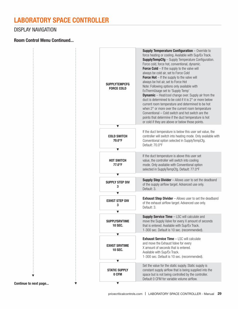
Room Control Menu Continued...
SUPPLYTEMPCFGFORCE COLD
Supply Temperature Configuration – Override to force heating or cooling. Available with Sup/Ex Track.SupplyTempCfg – Supply Temperature Configuration. Force cold, force hot, conventional, dynamic.Force Cold – If the supply to the valve will always be cold air, set to Force ColdForce Hot – If the supply to the valve will always be hot air, set to Force HotNote: Following options only available with ExThermUsage set to ‘Supply Temp’Dynamic – Heat/cool change over. Supply air from the duct is determined to be cold if it is 2° or more below current room temperature and determined to be hot when 2° or more over the current room temperatureConventional – Cold switch and hot switch are the points that determine if the duct temperature is hot or cold if they are above or below those points.
COLD SWITCH70.0°F
If the duct temperature is below this user set value, the controller will switch into heating mode. Only available with Conventional option selected in SupplyTempCfg. Default: 70.0*F
HOT SWITCH77.0°F
If the duct temperature is above this user set value, the controller will switch into cooling mode. Only available with Conventional option selected in SupplyTempCfg. Default: 77.0*F
SUPPLY STEP DIV3
Supply Step Divider – Allows user to set the deadband of the supply airflow target. Advanced use only.Default: 3.
EXHST STEP DIV3
Exhaust Step Divider – Allows user to set the deadband of the exhaust airflow target. Advanced use only.Default: 3.
SUPPLYSRVTIME10 SEC.
Supply Service Time – LSC will calculate and move the Supply Valve for every X amount of seconds that is entered. Available with Sup/Ex Track. 1-300 sec. Default is 10 sec. (recommended).
EXHST SRVTIME10 SEC.
Exhaust Service Time – LSC will calculate and move the Exhaust Valve for everyX amount of seconds that is entered. Available with Sup/Ex Track. 1-300 sec. Default is 10 sec. (recommended).
STATIC SUPPLY0 CFM
Set the value for the static supply. Static supply is constant supply airflow that is being supplied into the space but is not being controlled by the controller. Default 0 CFM for variable volume airflow.
Continue to next page...
30
LABORATORY SPACE CONTROLLERDISPLAY NAVIGATION
LABORATORY SPACE CONTROLLER - Manual | pricecriticalcontrols.com
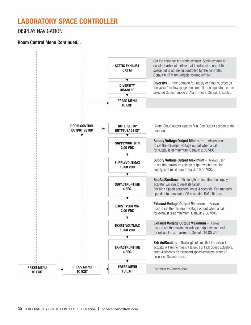
PRESS MENUTO EXIT
ROOM CONTROLOUTPUT SETUP
NOTE: SETUP OUTPTUSAGE1ST
Note: Setup output usages first. See Output section of the manual.
SUPPLYVOUTMIN2.00 VDC
Supply Voltage Output Minimum – Allows user to set the minimum voltage output when a call for supply is at minimum. Default: 2.00 VDC.
SUPPLYVOUTMAX10.00 VDC
Supply Voltage Output Maximum – Allows user to set the maximum voltage output when a call for supply is at maximum. Default: 10.00 VDC.
SUPACTRUNTIME4 SEC.
SupActRuntime – The length of time that the supply actuator will run to meet its target.For High Speed actuators, enter 4 seconds. For standard speed actuators, enter 95 seconds. Default: 4 sec.
EXHST VOUTMIN2.00 VDC
Exhaust Voltage Output Minimum – Allows user to set the minimum voltage output when a call for exhaust is at minimum. Default: 2.00 VDC.
EXHST VOUTMAX10.00 VDC
Exhaust Voltage Output Maximum – Allows user to set the maximum voltage output when a call for exhaust is at maximum. Default: 10.00 VDC.
EXHACTRUNTIME4 SEC.
Exh ActRuntime – The length of time that the exhaust actuator will run to meets it target. For High Speed actuators, enter 4 seconds. For standard speed actuators, enter 95 seconds. Default: 4 sec.
PRESS MENU TO EXIT Exit back to Service Menu.PRESS MENU
TO EXIT
Room Control Menu Continued...
STATIC EXHAUST0 CFM
Set the value for the static exhaust. Static exhaust is constant exhaust airflow that is exhausted out of the space but is not being controlled by the controller. Default 0 CFM for variable volume airflow.
DIVERSITYDISABLED
Diversity – If the demand for supply or exhaust exceeds the valves’ airflow range, the controller can go into the user selected Caution mode or Alarm mode. Default: Disabled.
PRESS MENUTO EXIT
LABORATORY SPACE CONTROLLER
31pricecriticalcontrols.com | LABORATORY SPACE CONTROLLER - Manual
DISPLAY NAVIGATION
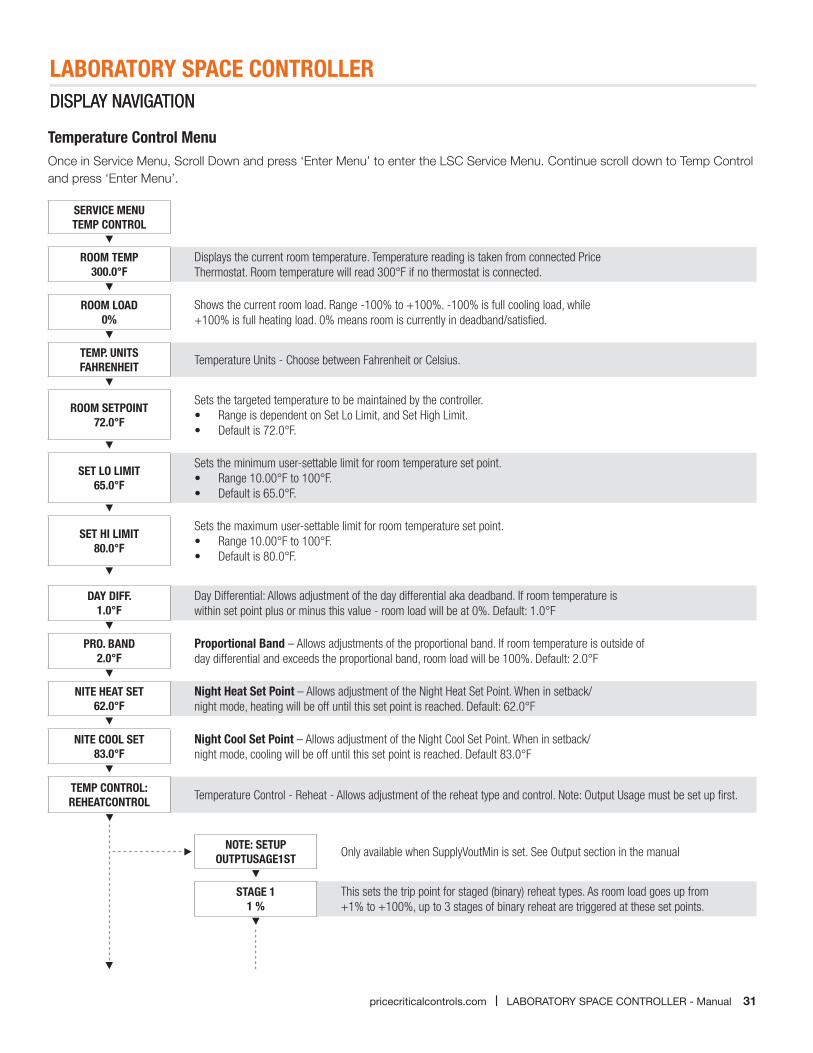
Temperature Control MenuOnce in Service Menu, Scroll Down and press ‘Enter Menu’ to enter the LSC Service Menu. Continue scroll down to Temp Control and press ‘Enter Menu’.
SERVICE MENUTEMP CONTROL
ROOM TEMP300.0°F
Displays the current room temperature. Temperature reading is taken from connected Price Thermostat. Room temperature will read 300°F if no thermostat is connected.
ROOM LOAD0%
Shows the current room load. Range -100% to +100%. -100% is full cooling load, while +100% is full heating load. 0% means room is currently in deadband/satisfied.
TEMP. UNITSFAHRENHEIT Temperature Units - Choose between Fahrenheit or Celsius.
ROOM SETPOINT72.0°F
Sets the targeted temperature to be maintained by the controller.• Range is dependent on Set Lo Limit, and Set High Limit.• Default is 72.0°F.
SET LO LIMIT65.0°F
Sets the minimum user-settable limit for room temperature set point.• Range 10.00°F to 100°F.• Default is 65.0°F.
SET HI LIMIT80.0°F
Sets the maximum user-settable limit for room temperature set point.• Range 10.00°F to 100°F.• Default is 80.0°F.
DAY DIFF.1.0°F
Day Differential: Allows adjustment of the day differential aka deadband. If room temperature is within set point plus or minus this value - room load will be at 0%. Default: 1.0°F
PRO. BAND2.0°F
Proportional Band – Allows adjustments of the proportional band. If room temperature is outside of day differential and exceeds the proportional band, room load will be 100%. Default: 2.0°F
NITE HEAT SET62.0°F
Night Heat Set Point – Allows adjustment of the Night Heat Set Point. When in setback/night mode, heating will be off until this set point is reached. Default: 62.0°F
NITE COOL SET83.0°F
Night Cool Set Point – Allows adjustment of the Night Cool Set Point. When in setback/night mode, cooling will be off until this set point is reached. Default 83.0°F
TEMP CONTROL:REHEATCONTROL Temperature Control - Reheat - Allows adjustment of the reheat type and control. Note: Output Usage must be set up first.
DISPLAY NAVIGATION
NOTE: SETUPOUTPTUSAGE1ST Only available when SupplyVoutMin is set. See Output section in the manual
STAGE 11 %
This sets the trip point for staged (binary) reheat types. As room load goes up from +1% to +100%, up to 3 stages of binary reheat are triggered at these set points.
LABORATORY SPACE CONTROLLER
32 LABORATORY SPACE CONTROLLER - Manual | pricecriticalcontrols.com
DISPLAY NAVIGATION
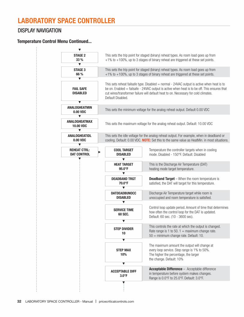
Temperature Control Menu Continued...
STAGE 2 33 %
This sets the trip point for staged (binary) reheat types. As room load goes up from +1% to +100%, up to 3 stages of binary reheat are triggered at these set points.
STAGE 3 66 %
This sets the trip point for staged (binary) reheat types. As room load goes up from +1% to +100%, up to 3 stages of binary reheat are triggered at these set points.
FAIL SAFEDISABLED
This sets reheat failsafe type. Disabled = normal - 24VAC output is active when heat is to be on. Enabled = failsafe - 24VAC output is active when heat is to be off. This ensures that cut wires/transformer failure will default heat to on. Necessary for cold climates. Default Disabled.
ANALOGHEATMIN 0.00 VDC This sets the minimum voltage for the analog reheat output. Default 0.00 VDC
ANALOGHEATMAX 10.00 VDC This sets the maximum voltage for the analog reheat output. Default: 10.00 VDC
ANALOGHEATIDL 0.00 VDC
This sets the idle voltage for the analog reheat output. For example, when in deadband or cooling. Default: 0.00 VDC. NOTE: Set this to the same value as HeatMin. in most situations.
REHEAT CTRL: DAT CONTROL
DISPLAY NAVIGATION
COOL TARGETDISABLED
Temperature the controller targets when in cooling mode. Disabled - 150°F. Default: Disabled
HEAT TARGET95.0°F
This is the Discharge Air Temperature (DAT) heating mode target temperature.
DEADBAND TRGT70.0°F
Deadband Target – When the room temperature is satisfied, the DAT will target for this temperature.
DATDEADBUNOCCDISABLED
Discharge Air Temperature target while room is unoccupied and room temperature is satisfied.
SERVICE TIME60 SEC.
Control loop update period. Amount of time that determines how often the control loop for the DAT is updated. Default: 60 sec. (10 - 3600 sec).
STEP DIVIDER10
This controls the rate at which the output is changed. Rate range is 1 to 50. 1 = maximum change rate. 50 = minimum change rate. Default: 10.
STEP MAX10%
The maximum amount the output will change at every loop service. Step range is 1% to 50%.The higher the percentage, the larger the change. Default: 10%
ACCEPTABLE DIFF3.0°F
Acceptable Difference – Acceptable difference in temperature before system makes changes.Range is 0.0°F to 25.0°F. Default: 3.0°F.
LABORATORY SPACE CONTROLLER
33pricecriticalcontrols.com | LABORATORY SPACE CONTROLLER - Manual
DISPLAY NAVIGATIONDISPLAY NAVIGATION
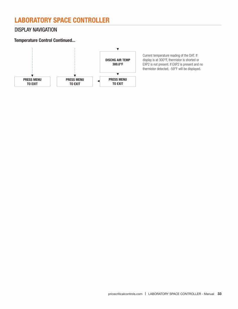
Temperature Control Continued...
PRESS MENUTO EXIT
DISCHG AIR TEMP300.0°F
Current temperature reading of the DAT. If display is at 300°F, thermistor is shorted or EXP2 is not present. If EXP2 is present and no thermistor detected, -59°F will be displayed.
PRESS MENU TO EXIT
PRESS MENUTO EXIT
34 LABORATORY SPACE CONTROLLER - Manual | pricecriticalcontrols.com
LABORATORY SPACE CONTROLLERMAINTENANCE
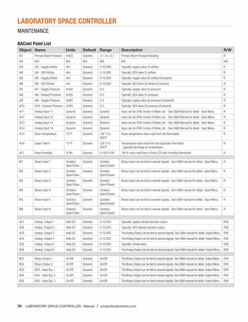
BACnet Point ListObject Name Units Default Range Description R/WAI1 Primary Room Pressure inH2O Dynamic -0.1 to +0.1 Primary Room Pressure Reading R
AI2 N/A N/A N/A N/A N/A N/A
AI3 AI3 - Supply Airflow cfm Dynamic 0-10,000 Typically: supply valve (1) airflow R
AI4 AI4 - GEX Airflow cfm Dynamic 0-10,000 Typically: GEX valve (1) airflow R
AI5 AI5 - Supply Airflow cfm Dynamic 0-10,000 Typically: supply valve (2) airflow (if present) R
AI6 AI6 - GEX Airflow cfm Dynamic 0-10,000 Typically: GEX Valve (2) airflow (if present) R
AI7 AI7 - Supply Pressure inH20 Dynamic 0-5 Typically: supply valve (1) pressure R
AI8 AI8 - Exhaust Pressure inH20 Dynamic 0-5 Typically: GEX valve (1) pressure R
AI9 AI9 - Supply Pressure inH20 Dynamic 0-5 Typically: supply valve (2) pressure (if present) R
AI10 AI10 - Exhaust Pressure inH20 Dynamic 0-5 Typically: GEX valve (2) pressure (if present) R
AI11 Analog Input 11 Dynamic Dynamic Dynamic Input can be CFM, Inches of Water, etc - See O&M Manual for detail. Input Menu. R
AI12 Analog Input 12 Dynamic Dynamic Dynamic Input can be CFM, Inches of Water, etc - See O&M Manual for detail. Input Menu. R
AI13 Analog Input 13 Dynamic Dynamic Dynamic Input can be CFM, Inches of Water, etc - See O&M Manual for detail. Input Menu. R
AI14 Analog Input 14 Dynamic Dynamic Dynamic Input can be CFM, Inches of Water, etc - See O&M Manual for detail. Input Menu. R
AI15 Room Temperature °C/°F Dynamic -59° F to 300°F
Room temperature value read from the thermostat R
AI16 Expan Therm °C/°F Dynamic -59° F to 300°F
Temperature value read from the Expansion thermistor - typically discharge air temperature
R
AI17 Room Humidity % RH Dynamic 0-100 % RH RH % value read from a Price LCD with humidity thermostat. R
BI1 Binary Input 1 Contatcs Open/Close
Dynamic Contatcs Open/Closed
Binary Input can be tied to several signals. See O&M manual for detail. Input Menu. R
BI2 Binary Input 2 Contatcs Open/Close
Dynamic Contatcs Open/Closed
Binary Input can be tied to several signals. See O&M manual for detail. Input Menu. R
BI3 Binary Input 3 Contatcs Open/Close
Dynamic Contatcs Open/Closed
Binary Input can be tied to several signals. See O&M manual for detail. Input Menu. R
BI4 Binary Input 4 Contatcs Open/Close
Dynamic Contatcs Open/Closed
Binary Input can be tied to several signals. See O&M manual for detail. Input Menu. R
BI5 Binary Input 5 Contatcs Open/Close
Dynamic Contatcs Open/Closed
Binary Input can be tied to several signals. See O&M manual for detail. Input Menu. R
BI6 Binary Input 6 Contatcs Open/Close
Dynamic Contatcs Open/Closed
Binary Input can be tied to several signals. See O&M manual for detail. Input Menu. R
AO1 Analog Output 1 Volts DC Dynamic 0-10 VDC Typically: supply valve(s) actuator output R/W
AO2 Analog Output 2 Volts DC Dynamic 0-10 VDC Typically: GEX valve(s) actuator output R/W
AO3 Analog Output 3 Volts DC Dynamic 0-10 VDC The Analog Output can be tied to several signals. See O&M manual for detail. Output Menu. R/W
AO4 Analog Output 4 Volts DC Dynamic 0-10 VDC The Analog Output can be tied to several signals. See O&M manual for detail. Output Menu. R/W
AO5 Analog Output 5 Volts DC Dynamic 0-10 VDC Typically: reheat valve R/W
AO6 Analog Output 6 Volts DC Dynamic 0-10 VDC The Analog Output can be tied to several signals. See O&M manual for detail. Output Menu. R/W
BO1 Binary Output 1 On/Off Dynamic On/Off The Binary Output can be tied to several signals. See O&M manual for detail. Output Menu. R/W
BO2 Binary Output 2 On/Off Dynamic On/Off The Binary Output can be tied to several signals. See O&M manual for detail. Output Menu. R/W
BO3 BO3 - Heat Stg. 1 On/Off Dynamic On/Off The Binary Output can be tied to several signals. See O&M manual for detail. Output Menu. R/W
BO4 BO4 - Heat Stg. 2 On/Off Dynamic On/Off The Binary Output can be tied to several signals. See O&M manual for detail. Output Menu. R/W
BO5 BO5 - Heat Stg. 3 On/Off Dynamic On/Off The Binary Output can be tied to several signals. See O&M manual for detail. Output Menu. R/W
35pricecriticalcontrols.com | LABORATORY SPACE CONTROLLER - Manual
LABORATORY SPACE CONTROLLERMAINTENANCE
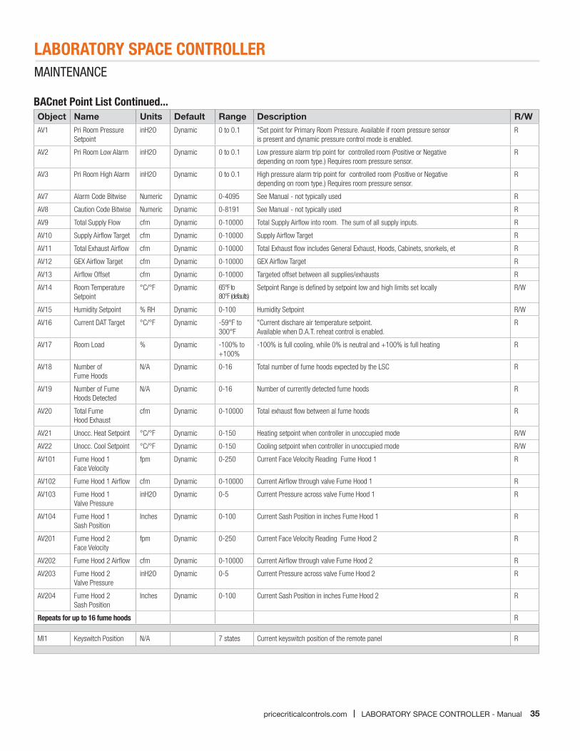
BACnet Point List Continued...Object Name Units Default Range Description R/WAV1 Pri Room Pressure
SetpointinH2O Dynamic 0 to 0.1 "Set point for Primary Room Pressure. Available if room pressure sensor
is present and dynamic pressure control mode is enabled.R
AV2 Pri Room Low Alarm inH2O Dynamic 0 to 0.1 Low pressure alarm trip point for controlled room (Positive or Negative depending on room type.) Requires room pressure sensor.
R
AV3 Pri Room High Alarm inH2O Dynamic 0 to 0.1 High pressure alarm trip point for controlled room (Positive or Negative depending on room type.) Requires room pressure sensor.
R
AV7 Alarm Code Bitwise Numeric Dynamic 0-4095 See Manual - not typically used R
AV8 Caution Code Bitwise Numeric Dynamic 0-8191 See Manual - not typically used R
AV9 Total Supply Flow cfm Dynamic 0-10000 Total Supply Airflow into room. The sum of all supply inputs. R
AV10 Supply Airflow Target cfm Dynamic 0-10000 Supply Airflow Target R
AV11 Total Exhaust Airflow cfm Dynamic 0-10000 Total Exhaust flow includes General Exhaust, Hoods, Cabinets, snorkels, et R
AV12 GEX Airflow Target cfm Dynamic 0-10000 GEX Airflow Target R
AV13 Airflow Offset cfm Dynamic 0-10000 Targeted offset between all supplies/exhausts R
AV14 Room Temperature Setpoint
°C/°F Dynamic 65°F to 80°F (defaults)
Setpoint Range is defined by setpoint low and high limits set locally R/W
AV15 Humidity Setpoint % RH Dynamic 0-100 Humidity Setpoint R/W
AV16 Current DAT Target °C/°F Dynamic -59°F to 300°F
"Current dischare air temperature setpoint. Available when D.A.T. reheat control is enabled.
R
AV17 Room Load % Dynamic -100% to +100%
-100% is full cooling, while 0% is neutral and +100% is full heating R
AV18 Number of Fume Hoods
N/A Dynamic 0-16 Total number of fume hoods expected by the LSC R
AV19 Number of Fume Hoods Detected
N/A Dynamic 0-16 Number of currently detected fume hoods R
AV20 Total Fume Hood Exhaust
cfm Dynamic 0-10000 Total exhaust flow between al fume hoods R
AV21 Unocc. Heat Setpoint °C/°F Dynamic 0-150 Heating setpoint when controller in unoccupied mode R/W
AV22 Unocc. Cool Setpoint °C/°F Dynamic 0-150 Cooling setpoint when controller in unoccupied mode R/W
AV101 Fume Hood 1 Face Velocity
fpm Dynamic 0-250 Current Face Velocity Reading Fume Hood 1 R
AV102 Fume Hood 1 Airflow cfm Dynamic 0-10000 Current Airflow through valve Fume Hood 1 R
AV103 Fume Hood 1 Valve Pressure
inH2O Dynamic 0-5 Current Pressure across valve Fume Hood 1 R
AV104 Fume Hood 1 Sash Position
Inches Dynamic 0-100 Current Sash Position in inches Fume Hood 1 R
AV201 Fume Hood 2 Face Velocity
fpm Dynamic 0-250 Current Face Velocity Reading Fume Hood 2 R
AV202 Fume Hood 2 Airflow cfm Dynamic 0-10000 Current Airflow through valve Fume Hood 2 R
AV203 Fume Hood 2 Valve Pressure
inH2O Dynamic 0-5 Current Pressure across valve Fume Hood 2 R
AV204 Fume Hood 2 Sash Position
Inches Dynamic 0-100 Current Sash Position in inches Fume Hood 2 R
Repeats for up to 16 fume hoods R
MI1 Keyswitch Position N/A 7 states Current keyswitch position of the remote panel R
36 LABORATORY SPACE CONTROLLER - Manual | pricecriticalcontrols.com
LABORATORY SPACE CONTROLLERMAINTENANCE
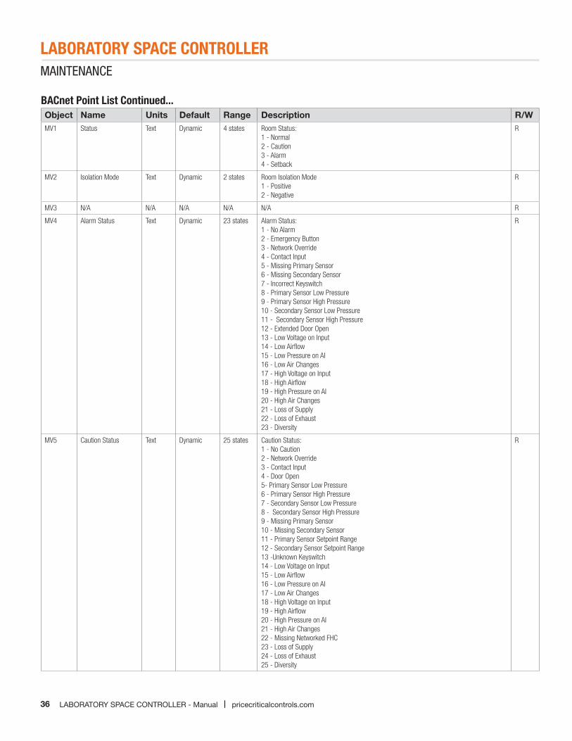
BACnet Point List Continued...Object Name Units Default Range Description R/WMV1 Status Text Dynamic 4 states Room Status:
1 - Normal2 - Caution3 - Alarm4 - Setback
R
MV2 Isolation Mode Text Dynamic 2 states Room Isolation Mode1 - Positive2 - Negative
R
MV3 N/A N/A N/A N/A N/A R
MV4 Alarm Status Text Dynamic 23 states Alarm Status:1 - No Alarm2 - Emergency Button3 - Network Override4 - Contact Input5 - Missing Primary Sensor6 - Missing Secondary Sensor7 - Incorrect Keyswitch8 - Primary Sensor Low Pressure9 - Primary Sensor High Pressure10 - Secondary Sensor Low Pressure11 - Secondary Sensor High Pressure12 - Extended Door Open13 - Low Voltage on Input14 - Low Airflow15 - Low Pressure on AI16 - Low Air Changes17 - High Voltage on Input18 - High Airflow19 - High Pressure on AI20 - High Air Changes21 - Loss of Supply22 - Loss of Exhaust23 - Diversity
R
MV5 Caution Status Text Dynamic 25 states Caution Status:1 - No Caution2 - Network Override3 - Contact Input4 - Door Open5- Primary Sensor Low Pressure6 - Primary Sensor High Pressure7 - Secondary Sensor Low Pressure8 - Secondary Sensor High Pressure9 - Missing Primary Sensor10 - Missing Secondary Sensor11 - Primary Sensor Setpoint Range12 - Secondary Sensor Setpoint Range13 -Unknown Keyswitch14 - Low Voltage on Input15 - Low Airflow16 - Low Pressure on AI17 - Low Air Changes18 - High Voltage on Input19 - High Airflow20 - High Pressure on AI21 - High Air Changes22 - Missing Networked FHC23 - Loss of Supply24 - Loss of Exhaust25 - Diversity
R
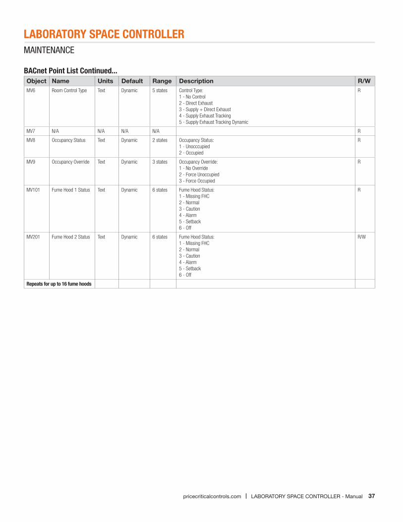
37pricecriticalcontrols.com | LABORATORY SPACE CONTROLLER - Manual
LABORATORY SPACE CONTROLLERMAINTENANCE
BACnet Point List Continued...Object Name Units Default Range Description R/WMV6 Room Control Type Text Dynamic 5 states Control Type:
1 - No Control2 - Direct Exhaust3 - Supply + Direct Exhaust4 - Supply Exhaust Tracking5 - Supply Exhaust Tracking Dynamic
R
MV7 N/A N/A N/A N/A R
MV8 Occupancy Status Text Dynamic 2 states Occupancy Status:1 - Unocccupied2 - Occupied
R
MV9 Occupancy Override Text Dynamic 3 states Occupancy Override:1 - No Override2 - Force Unoccupied3 - Force Occupied
R
MV101 Fume Hood 1 Status Text Dynamic 6 states Fume Hood Status:1 - Missing FHC2 - Normal3 - Caution4 - Alarm5 - Setback6 - Off
R
MV201 Fume Hood 2 Status Text Dynamic 6 states Fume Hood Status:1 - Missing FHC2 - Normal3 - Caution4 - Alarm5 - Setback6 - Off
R/W
Repeats for up to 16 fume hoods

This document contains the most current product information as of this printing. For the most up-to-date product information, please go to www.price-hvac.com.
© 2015 Price Industries Limited. All rights reserved.