Embed Size (px)
Citation preview

“Willem Dafoe Kart”: Electric Go-Kart
Manny Walton and Michael Machlin
1 Abstract
The purpose of this project was to plan and build an electric go-kart. We found this especially important given that electric motors are increasingly replacing gasoline engines in today’s automobiles since they are more environmentally friendly and easier to maintain, among other reasons. In addition, we both improved our comprehension of electrical engineering, as we learned how to use 555-timing oscillators for our turn signals, wired a sliding potentiometer to act as a voltage divider throttle, created a horn with a momentary pushbutton switch and a salvaged car horn, and wired all the components together through a 36 V motor controller. For the project, we used a frame from a go-kart previously powered by a gas motor.
2 Introduction
For this second semester project, we chose to design and build an electric go-kart. We were interested in converting a gas engine vehicle to run off of an electric motor and batteries. We feel a need to help improve the planet, so we used the second-semester project as a small-scale attempt to push the world into the future, one step at a time. Our main goals behind the fabrication of our go-kart were that it be aesthetically pleasant, easy to operate, quiet, and environmentally friendly. The kart’s purpose is to provide the driver with great enjoyment while being able to navigate tight turns and explore typically non-vehicle friendly environments, such as the Menlo School campus. The go-kart includes a small electric DC motor, powered by multiple rechargeable AGM (absorbable glass mat) lead-acid batteries. In order to accelerate, an accelerator pedal is connected via a spring to a linear 10 kΩ sliding potentiometer. The slide pot is connected to a motor
This paper was written for Dr. James Dann’s Applied Science Research class in the spring of 2013.

46 Manny Walton & Michael Machlin
controller, which in turn will alter the voltage going to the motor by rapidly turning the power from the batteries on and off (thereby achieving pulse width modulation, or PWM). We were inspired by the go-kart created by Jack Lucas ’12, from which we are reusing the frame, seat, and steering mechanism while rebuilding the drive and electrical systems. Originally, we planned on creating a drill-powered go-kart, or “drill kart,” like the one built by Gever Tully and described in MAKE Magazine. [5] Its relatively low materials cost and ease of building was appealing to us. However, the drill kart appears difficult to steer, as the single rear caster allows for free rotation while attempting to steer by varying the drills’ rotational speeds. This makes it more of a novelty item than a useable, safe vehicle, so we decided to build a traditional, albeit untraditionally driven, go-kart instead. From this adventure we hope to gain further understanding of electrical systems in vehicles, learn more building and craftsmanship skills, and have fun driving around in our kart once it is complete.
3 History
According to a report from Ward’s Auto two-and-a-half years ago, the total number of vehicles in the world finally surpassed the 1 billion mark, as the global vehicle population jumped from 980 million in 2009 to 1.015 billion in 2010. [1] Although electric cars and hybrids are responsible for 3% of this data, this information still serves as the driving force behind lingering doubts about the world’s supply of fossil fuels. [2] Looking at this issue from another vantage point, human activities, such as the burning of fossil fuels, release CO2, “an important heat-trapping (greenhouse) gas.” [3] Prior to the rapid spike in the atmospheric concentration of CO2 since 1950, the last record set for carbon dioxide in Earth’s atmosphere was 300 parts per million; a record set 375,000 years ago. Today, that number stands at 395 parts per million, and still continues to grow.
In the wake of this distressing information, more and more solutions are being devised to combat these issues. One of these solutions involves lessening the amount of gasoline-fueled cars on the road, and replacing them with electric vehicles. Although electric vehicles have

THE MENLO ROUNDTABLE 47
been around since the 1830s as cost-effective substitutes for steam or internal combustion engines (following Dutch inventor Sibrandus Stratingh’s creation of an electromagnet cart), they have become more feasible for average consumers. Automakers have found ways to adapt to growing environmental standards and changes to everyday practicality. For example, in the ’70s, amidst modern concerns of exhausting fuel supplies, the Vanguard-Sebring CitiCar was supposed to launch electric car sales. However, these aspirations were short lived as the CitiCar’s fuel cells had to be powered by some sort of fuel anyways, defeating the purpose of a non-fuel reliant automobile. Forty years later, countless strides have been made in improving the design of electric vehicles, and in 2011, the highly successful Chevrolet Volt was released with “a gas-powered engine that kicks in as a generator to recharge the car’s batteries.” [4]
4 CAD Drawings
In all CAD drawings, the kart scale (in inches) is 1:2.1
Figure 1: CAD drawing front view. Width of kart from outer side of left wheel to outer side of right wheel: 22.7”; height of kart from bottom of wheel to top of wheel: 13.9”; length of kart from front wheel to rear wheel: 62.4”

48 Manny Walton & Michael Machlin
Figure 2: Front view of kart.

THE MENLO ROUNDTABLE 49
Figure 3: CAD drawing rear view, trunk base dimensions. Length and width of trunk base: 17.1” x 10.2”

50 Manny Walton & Michael Machlin
Figure 4: Rear view

THE MENLO ROUNDTABLE 51
Figure 5: CAD drawing rear view, battery pack dimensions. Length, width, and height of batteries: 5.9” x 6.4” x 6.1”

52 Manny Walton & Michael Machlin
Figure 6: Rear view showing battery pack

THE MENLO ROUNDTABLE 53
Figure 7: CAD drawing rear view, motor controller dimensions. Length and width of motor controller: 2.8” x 3.7”
Figure 8: CAD drawing rear view, motor dimensions. Motor length 5.9”, diameter 4.4”

54 Manny Walton & Michael Machlin
Figure 9: CAD drawing top view. Length of kart from back of trunk base to front wheels: 66.26”

THE MENLO ROUNDTABLE 55
V Theory
Our go-kart is driven by an electric motor, which is controlled by a motor controller designed for electric scooters. The controller is connected to three 12 V batteries, the motor itself, and our throttle system, in addition to accessory systems such as ignition, turn signals, and brakes.
The motor controller is connected to our throttle circuit, and interprets the throttle input to regulate power to the motor. As ours is a DC (direct current) motor, its rotational speed is regulated by sending “pulses” of voltage to the motor. These pulses are always at the maximum voltage, and their width (time at full voltage) is varied to cause the desired average voltage value and the rotational speed. Since we have three 12 V batteries, providing constant power from all three would result in 36 V to the motor, causing it to spin at its maximum speed. If, for example, we press the throttle down halfway, the controller will provide full voltage 50% of the time, causing an average voltage of 18 V. This causes it to spin at half its maximum RPM. This method of sending varying pulses to a DC motor to affect the average voltage perceived by the motor is known as pulse-width modulation, or PWM. [6]

56 Manny Walton & Michael Machlin
Figure 10: PWM used to achieve 0 V, 1.25 V, 2.5 V, 3.75 V, and 5 V, top to bottom [7]
The throttle itself uses a voltage divider, consisting of a 10 kΩ sliding potentiometer. The sliding potentiometer is attached with a spring to the go-kart’s accelerator pedal, so pressing the pedal adjusts its position. Depending on the position of the sliding potentiometer, its resistance will vary from 0 kΩ to 10 kΩ (hence its rating). If the sliding potentiometer’s resistance is increased, less voltage will be across it (since V=IR, and as resistance increases so will voltage) and will instead be sent to the controller’s throttle input. If the sliding potentiometer’s resistance is decreased, more voltage will be across it to the ground loop, and throttle input to the controller will decrease in voltage. The controller determines, based on the throttle input, how much to vary the pulse width using the previously described PWM. A potential way to wire the potentiometer would be to wire it in series with a resistor at a fixed value of, for example, 3.0 kΩ. As seen from a sample calculation below, placing a resistor in series with the potentiometer would increase the amount of sliding distance needed to achieve a maximum Vout of 5 V. Because the spring on the go-kart only moves a length of half of

THE MENLO ROUNDTABLE 57
the sliding distance on the potentiometer, we chose not to include a resistor in series. This decreased the necessary sliding distance to get to a full output of 5 V.
Sample Calculation:
Vout = I*Rthrottle
I = Vtotal/Rtotal = 5 V/(R1+Rthrottle), thusVout = I*Rthrottle=[5 V)*(Rthrottle)]/[R1+Rthrottle]Using a 3.0 kΩ resistor in series with the potentiometer):Vout=3.85 VNot using a resistor in series (thus R1=0): (Vout)=(5 V)*(Rthrottle)/[(R1)+(Rthrottle)]=(5 V)*10 kΩ/10 kΩ =5.0 V
Figure 11: Throttle circuit with sliding potentiometer (variable resistor)

58 Manny Walton & Michael Machlin
The electric motor for our go-kart, however, is a 36 V, 1000 W, 4-pole, 20-phase brushed DC motor. A basic variation of this type of motor spins as a result of a commutator reversing the direction of the current in an armature. The armature is a rotating axle perpendicular to the motor’s shaft with coils wrapped around it.
Figure 12: Faraday’s Law, Maxwell’s Equation
In correspondence with Faraday’s Law, as a current passes through a closed coil of wire, a resultant magnetic field is perpendicularly directed outward, where the integral of E*ds is equal to voltage, and (d/dt)* ΦB is equal to the derivative of magnetic flux. [8] What this means is that as flux increases, you get more voltage and a higher resultant magnetic field perpendicular to the coil, and as flux decreases, there is less voltage and a lesser resultant magnetic field. Also in the motor are two magnets of opposite poles on both ends of the motor’s interior. When current is sent flowing through the armature, a magnetic field is created (one end of the armature experiences an upward force while the other end experiences a downward force). Consequently, they both are attracted to their corresponding magnet on the wall of the interior, causing the axle to spin (see Figure 13). While the ends of the armature are positioned in between both magnets, the axle rotates freely. At this point, the commutator reverses the current in the coil and the magnetic field is reversed, causing the ends of the armature to be attracted to the other magnet that they were not previously attracted to. This allows for the axle to spin another half-turn. Other alternatives with a brushed DC motor include having the field coils connected parallel to the armature coils (see Figure 14).

THE MENLO ROUNDTABLE 59
Figure 13: Series wound DC Motor [9]
Figure 14: Shunt wound DC motor [10]
Our motor functions similarly to the electric motors that the Applied Science Research class built in the first semester. Briefly, our electric motor from the first semester consisted of two electromagnets facing each other on opposite ends of the frame. In the middle of both electromagnets, our 3D-printed axle had four permanent earth magnets, and on the end of the axle were eight permanent sensor

60 Manny Walton & Michael Machlin
magnets. When one of the sensor magnets reached our stationery Hall chip, the Hall effect would cause the Hall chip to complete the circuit that directs current into the electromagnets. Once the electromagnets are turned on, they both repel two of the earth magnets on the axle, causing for the axle to rotate. Then, once the next sensor magnet reaches the Hall chip, the Hall chip turns the circuit off, allowing for the iron coil of the electromagnets to attract the other two earth magnets on the axle, making the axle rotate until the next of eight sensor magnets turns the circuit back on.
Also included in our go-kart are left- and right-turn signals. Instead of just manually flipping the lights on and off, we are using a 555 oscillator powered by a VCC of 5 V from the controller. The idea behind a 555 oscillator is that the frequency at which a capacitor continually charges and discharges (and the values of the resistors in the circuit) is what ultimately governs how fast whatever is connected to the circuit turns on and off. When the trigger input reaches a certain threshold voltage (⅓ VCC) from the discharging of the capacitor, a positive voltage is directed out towards whatever is connected to the circuit (our lights). In the time frame that the voltage to the lights is at full output, the capacitor recharges back up to ⅔ VCC , at which point the voltage directed to the lights is now shut off (see Figure 15). In order to change the frequency at which the capacitor charges and discharges, values of R2 and R3 can be changed (see Figure 16). The time frame for when the output voltage to the lights is “on” (t1) is equal to:
0.693(R2+R3)*C
The time frame for when the output voltage to the lights is “off ” (t2) is equal to: [10]
0.693*R3*C

Figure 15: Graphs of capacitor charge and output voltage over time [11]
Figure 16: Example circuit using a 555 oscillator [12]
THE MENLO ROUNDTABLE 61
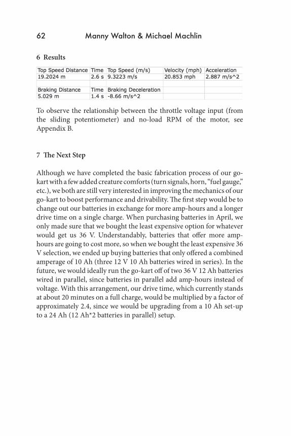
6 Results
To observe the relationship between the throttle voltage input (from the sliding potentiometer) and no-load RPM of the motor, see Appendix B.
7 The Next Step Although we have completed the basic fabrication process of our go-kart with a few added creature comforts (turn signals, horn, “fuel gauge,” etc.), we both are still very interested in improving the mechanics of our go-kart to boost performance and drivability. The first step would be to change out our batteries in exchange for more amp-hours and a longer drive time on a single charge. When purchasing batteries in April, we only made sure that we bought the least expensive option for whatever would get us 36 V. Understandably, batteries that offer more amp-hours are going to cost more, so when we bought the least expensive 36 V selection, we ended up buying batteries that only offered a combined amperage of 10 Ah (three 12 V 10 Ah batteries wired in series). In the future, we would ideally run the go-kart off of two 36 V 12 Ah batteries wired in parallel, since batteries in parallel add amp-hours instead of voltage. With this arrangement, our drive time, which currently stands at about 20 minutes on a full charge, would be multiplied by a factor of approximately 2.4, since we would be upgrading from a 10 Ah set-up to a 24 Ah (12 Ah*2 batteries in parallel) setup.
62 Manny Walton & Michael Machlin

Another option for increasing the practicality and convenience of our go-kart would be to address the issue of charging our batteries. During this project, we found out that the charger we were supposed to use to charge 36 V of battery was not functioning properly with the motor controller. When we left the charger on for a full night to charge the batteries, the voltage across the batteries only increased by .3 V. Also, when we were trying once more to charge our batteries with the factory charger, we ended up frying the charger itself because we tried to connect the batteries directly to the charge without first connecting the charger to the wall. Consequently, we were forced to charge our batteries with a 60 V DC power supply set at 44.5 V (the original output voltage that our charger would have given out to the batteries). Although our charge time right now is about 5 hours, we would still like to make it faster, considering that our drive time is about 6.7% of the charge time. We could achieve a faster charge time with a 50 W, 5 A, 36 V smart charger, which would decrease our charge time to about 2.5 hours, considering that we are only getting about 2.5 A from the voltage source. Also, a smart charger would allow us to charge the batteries overnight, since it will stop charging the batteries once they have reached their full charge (something that we can’t do now with the voltage source).
THE MENLO ROUNDTABLE 63

8 Appendices
8.1 Appendix A: Parts List
Part Description Purpose Cost Where to buySteering wheel replace sharp
old one$30 gokartsupply.com
36 V 1000 W motor
drive the rear wheels
$99 monsterscooterparts.com
3x 12 V, 10 Ah SLA batteries
power the motor
$32.99 each ($99 total)
monsterscooterparts.com
2x ¾” x 16 hex nuts
hold rear wheels in place (bolts missing)
$1.50 each Ace Hardware
36 V 1000 W motor controller
Regulate the flow of our circuit, and power everything from our batteries
$47 monsterscooterparts.com
36 V battery charger
Charge batteries
$28 monsterscooterparts.com
Locking ignition switch
prevent accidental/unwanted vehicle usage
$15 monsterscooterparts.com
10-tooth sprocket allow new motor to work with old chain and drive sprocket
Unknown Still looking
Sliding Potentiometer
Direct different amounts of voltage into the controller (and then to the motor)
N/A Classroom
64 Manny Walton & Michael Machlin

THE MENLO ROUNDTABLE 65
8.2 Appendix B: Graph of Potentiometer Output Voltage vs Motor RPM
9 Bibliography
[1] Sousanis, John. “World Vehicle Population Tops 1 Billion Units.” Ward’s Auto. Last modified August 15, 2011. Accessed February 5, 2013. http://wardsauto.com/ar/world_vehicle_population_110815.
[2] Scheid, Jean. “How Many Hybrid Cars Are on the Road?” Love to Know Green Living. Last modified 2013. Accessed February 5, 2013.http://greenliving.lovetoknow.com/How_Many_Hybrid_Cars_Are_on_the_Road
[3] “Climate Change: Key Indicators.” NASA. Last modified January 23, 2013. Accessed February 5, 2013. http://climate.nasa.gov/key_indicators#co2.
[4] Romero, Frances. “A Brief History of the Electric Car.” TIME. Last modified January 13, 2009. Accessed February 5, 2013.http://www.time.com/time/business/article/0,8599,1871282,00.html.

[5] Tully, Gever. “Drill Kart.” MAKE Magazine. Accessed January 22, 2013. http://makeprojects.com/Project/Drill+Kart/704/1#.USvbK79dUoc.
[6] “Pulse-width modulation.” Wikipedia. Accessed March 21, 2013. http://en.wikipedia.org/wiki/Pulse-width_modulation. [7] “PWM.” Arduino. Accessed March 22, 2013. http://arduino.cc/en/Tutorial/PWM.
[8] “Electromagnetic Induction.” Wikipedia. Accessed April 21, 2013. http://en.wikipedia.org/wiki/Faraday%27s_law_of induction# Faraday.27s_law. [9] DC Motor Parts. Photograph. TutorVista. Accessed March 21, 2013. http://images.tutorvista.com/content/magnetic-effects-electric-current/dc-motor-parts.jpeg.
[10] “555 Oscillator Tutorial.” Electronics-Tutorials.ws. Last modified 2013. Accessed March 15, 2013. http://www.electronics-tutorialjavascript:void(0)s.ws/waveforms/555_oscillator.html. [11] “The DC Shunt Motor.” Wisc-Online. Accessed March 22, 2013. http://www.wisc-online.com/objects/ViewObject.aspx?ID=IAU13708.
[12] 555 Oscillator Circuit. Photograph. Tumblr. Accessed March 22, 2013. http://media.tumblr.com/tumblr_lig85gX6th1qf00w4.jpg.
66 Manny Walton & Michael Machlin