Embed Size (px)
Citation preview
Power Turbo-Systems
Plants
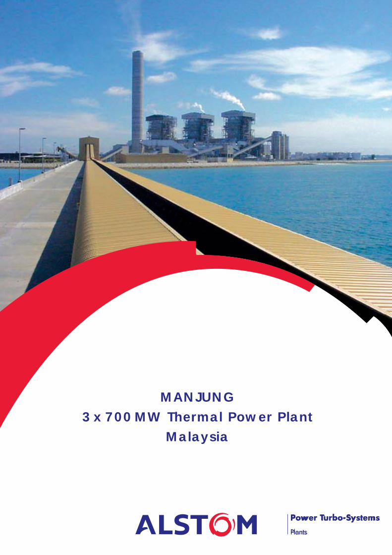
MANJUNG3x700MW Thermal Power Plant
Malaysia
General Presentation
2
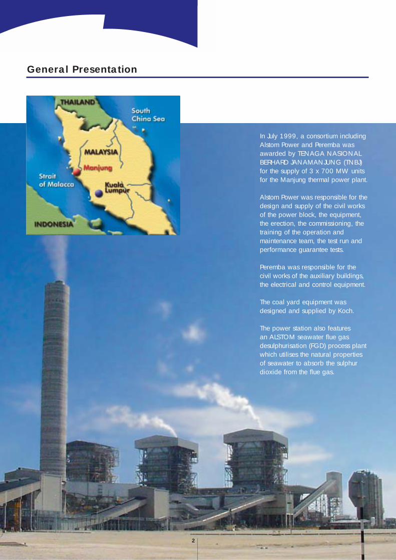
In July 1999, a consortium includingAlstom Power and Peremba wasawarded by TENAGA NASIONALBERHARD JANAMANJUNG (TNBJ)for the supply of 3 x 700 MW unitsfor the Manjung thermal power plant.
Alstom Power was responsible for thedesign and supply of the civil worksof the power block, the equipment,the erection, the commissioning, thetraining of the operation andmaintenance team, the test run andperformance guarantee tests.
Peremba was responsible for thecivil works of the auxiliary buildings,the electrical and control equipment.
The coal yard equipment wasdesigned and supplied by Koch.
The power station also featuresan ALSTOM seawater flue gasdesulphurisation (FGD) process plantwhich utilises the natural propertiesof seawater to absorb the sulphurdioxide from the flue gas.
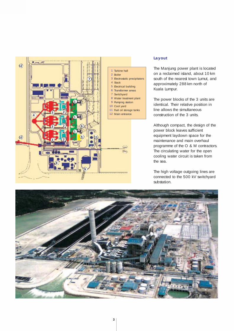
Layout
The Manjung power plant is locatedon a reclaimed island, about 10 kmsouth of the nearest town Lumut, andapproximately 288km north ofKuala Lumpur.
The power blocks of the 3 units areidentical. Their relative position inline allows the simultaneousconstruction of the 3 units.
Although compact, the design of thepower block leaves sufficientequipment laydown space for themaintenance and main overhaulprogramme of the O & M contractors.The circulating water for the opencooling water circuit is taken fromthe sea.
The high voltage outgoing lines areconnected to the 500 kV switchyardsubstation.
3
Turbine hallBoilerElectrostatic precipitatorsStackElectrical buildingTransformer areasSwitchyardWater treatment plantPumping stationCool yardFuel oil storage tanksMain entrance
123456789
1011122
2
2
3
3
3
4
5
6
7
8
9
1
1
1
10 11
12
4
Plant Description - Main Components
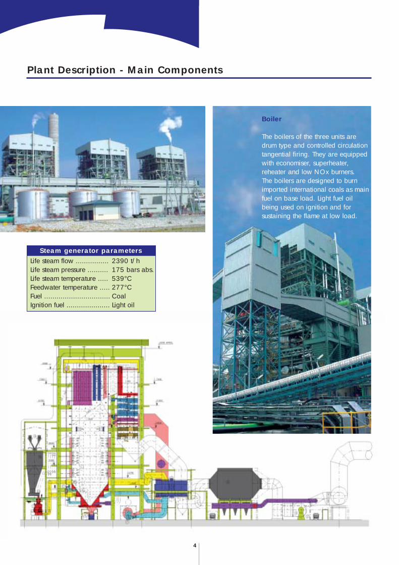
Boiler
The boilers of the three units aredrum type and controlled circulationtangential firing. They are equippedwith economiser, superheater,reheater and low NOx burners.The boilers are designed to burnimported international coals as mainfuel on base load. Light fuel oilbeing used on ignition and forsustaining the flame at low load.
2390 t/h175 bars abs.539°C277°CCoalLight oil
Steam generator parametersLife steam flow ................Life steam pressure ..........Life steam temperature .....Feedwater temperature .....Fuel ................................Ignition fuel .....................
Turbine
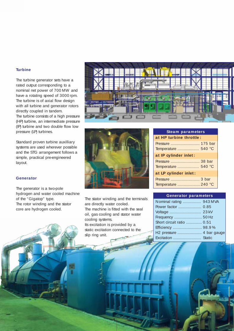
The turbine generator sets have arated output corresponding to anominal net power of 700MW andhave a rotating speed of 3000 rpm.The turbine is of axial flow designwith all turbine and generator rotorsdirectly coupled in tandem.The turbine consists of a high pressure(HP) turbine, an intermediate pressure(IP) turbine and two double flow lowpressure (LP) turbines.
Standard proven turbine auxilliarysystems are used wherever possibleand the STG arrangement follows asimple, practical pre-engineeredlayout.
Generator
The generator is a two-polehydrogen and water cooled machineof the “Gigatop” type.The rotor winding and the statorcore are hydrogen cooled.
The stator winding and the terminalsare directly water cooled.The machine is fitted with the sealoil, gas cooling and stator watercooling systems.Its excitation is provided by astatic excitation connected to theslip ring unit.
5
175 bar540 °C
Steam parametersat HP turbine throttle :Pressure ........................Temperature .................
38 bar540 °C
at IP cylinder inlet :Pressure ........................Temperature .................
3 bar240 °C
at LP cylinder inlet :Pressure ........................Temperature ..................
943 MVA0.8523 kV50 Hz0.5198.9 %4 bar gaugeStatic
Generator parametersNominal rating ...............Power factor ...................Voltage ..........................Frequency .......................Short circuit ratio .............Efficiency ........................H2 pressure ....................Excitation .......................
Circulating water pumps
The circulating water system takescooling water from the sea to thethree condensers by means of six50% duty concrete volute type maincooling water pumps.
Feedwater heating plant
The feedwater heating plant includesfour LP heaters arranged in series, withLP1 & 2 located in the condenser neck,one feedwater tank equipped with adeaerator and three HP heaters. Allthe feedwater heating equipment isinstalled horizontally.
Feedwater pumps
The feedwater pump system iscomposed of 3 x 50% feedwatermotor-pump sets, each including :· a booster pump,· a main pump,· a variable speed hydraulic coupling,· a drive motor.
Condensate extraction pumps
The condensate water is drawn fromthe condenser hotwell by two 100 %motor-pump sets. Each pump is of themultistage, vertical type with barrel.
Condenser
The condenser is of the single pass,surface type, comprising four titaniumtube bundles. Each tube bundle hasits own inlet and outlet water box suchthat the condenser can be consideredas two half-condensers of two bundlesin parallel. The condenser neck isconnected to the LP turbine exhaustbox by a suitable flexible bellow.
Mechanical Equipment
6
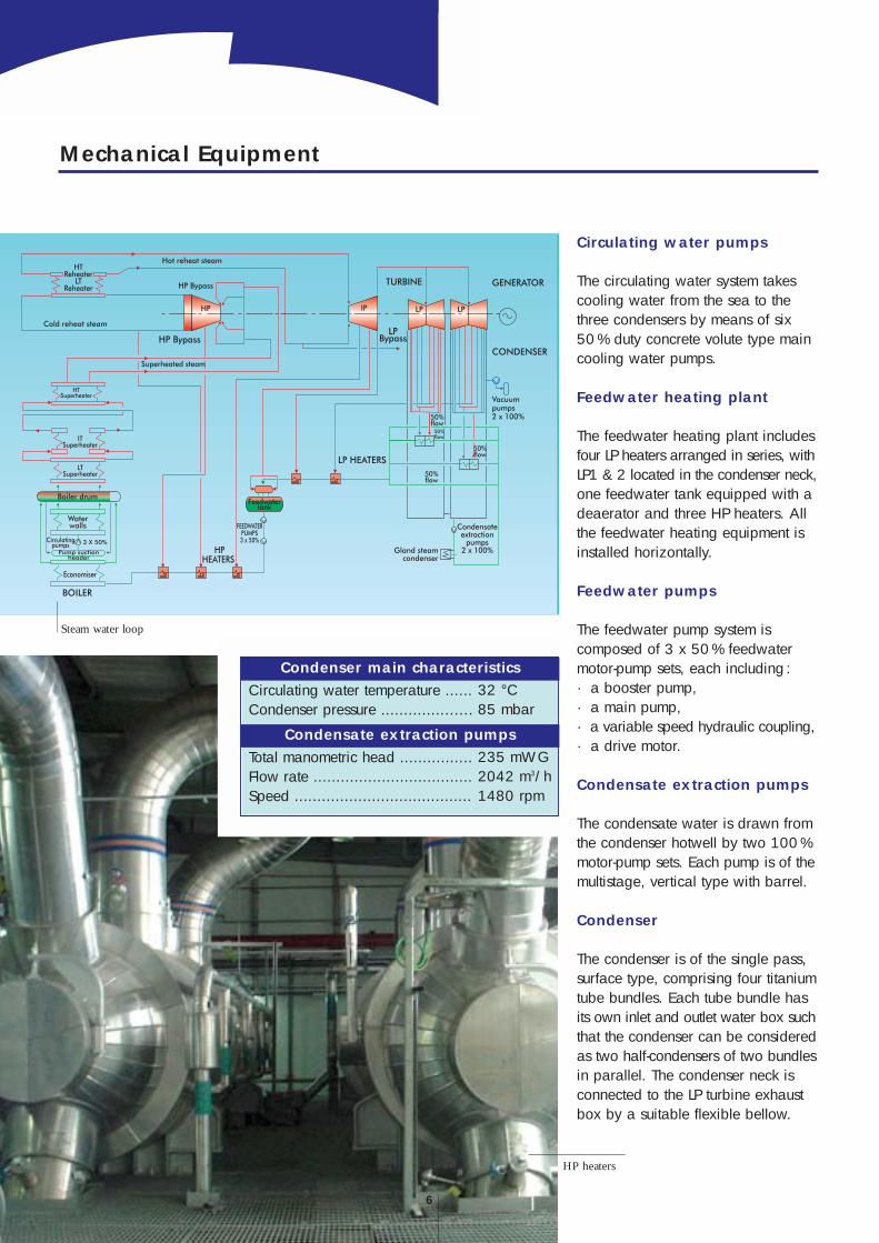
HP heaters
Steam water loop
32 °C 85 mbar
Condenser main characteristicsCirculating water temperature ......Condenser pressure ....................
235 mWG2042 m3/h1480 rpm
Condensate extraction pumpsTotal manometric head ................Flow rate ...................................Speed .......................................
7
Electrical Distribution - Control and Instrumentation
Electrical equipment
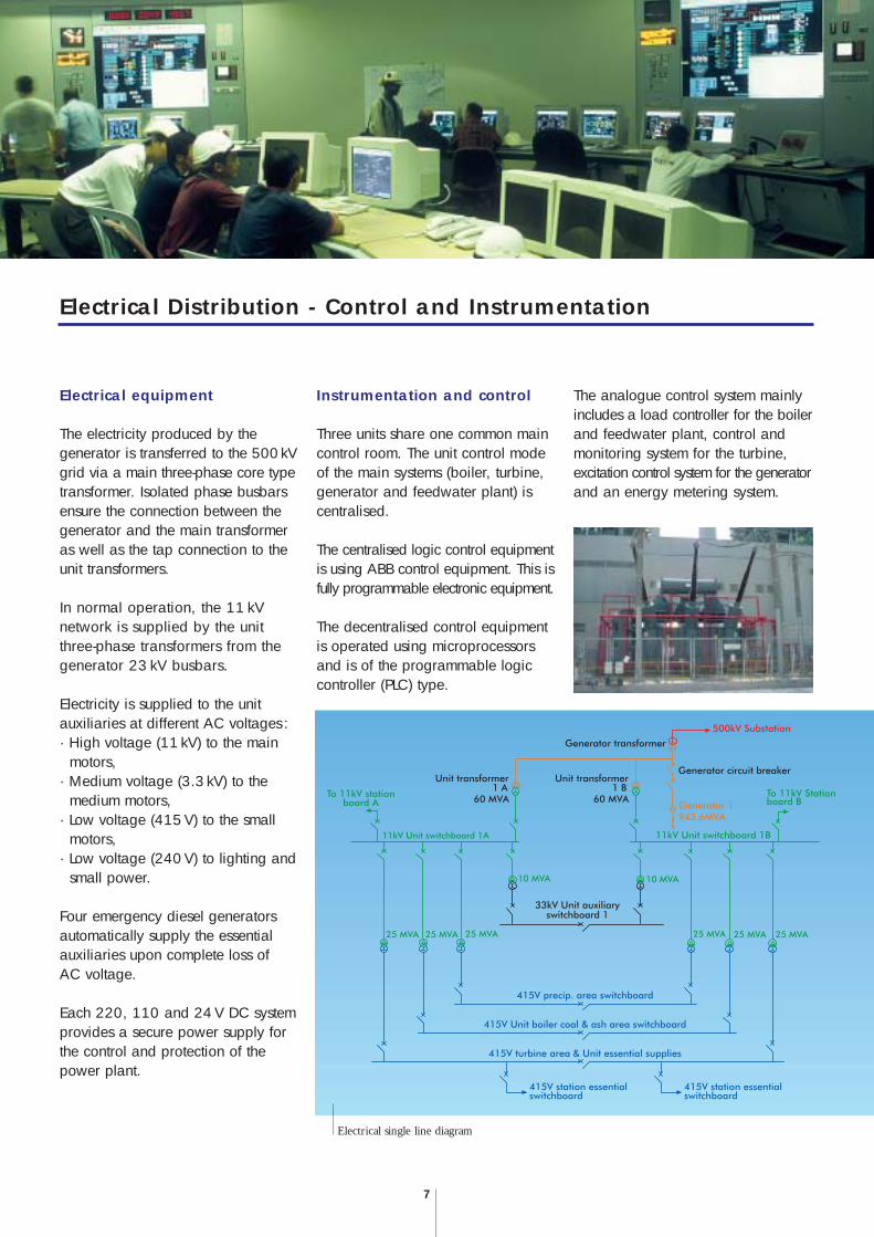
The electricity produced by thegenerator is transferred to the 500kVgrid via a main three-phase core typetransformer. Isolated phase busbarsensure the connection between thegenerator and the main transformeras well as the tap connection to theunit transformers.
In normal operation, the 11 kVnetwork is supplied by the unitthree-phase transformers from thegenerator 23 kV busbars.
Electricity is supplied to the unitauxiliaries at different AC voltages :· High voltage (11 kV) to the main
motors,· Medium voltage (3.3 kV) to the
medium motors,· Low voltage (415V) to the small
motors,· Low voltage (240V) to lighting and
small power.
Four emergency diesel generatorsautomatically supply the essentialauxiliaries upon complete loss ofAC voltage.
Each 220, 110 and 24V DC systemprovides a secure power supply forthe control and protection of thepower plant.
Instrumentation and control
Three units share one common maincontrol room. The unit control modeof the main systems (boiler, turbine,generator and feedwater plant) iscentralised.
The centralised logic control equipmentis using ABB control equipment. This isfully programmable electronic equipment.
The decentralised control equipmentis operated using microprocessorsand is of the programmable logiccontroller (PLC) type.
The analogue control system mainlyincludes a load controller for the boilerand feedwater plant, control andmonitoring system for the turbine,excitation control system for the generatorand an energy metering system.
Electrical single line diagram

ALSTOM Power Centrales - 2, quai Michelet/4, avenue André Malraux - 92309 Levallois-Perret Cedex (France)Tel. + 33 (0) 1 41 49 20 00 - Fax +33 (0) 1 41 49 24 85 - www.power.alstom.com
“ -
ALS
TOM
- 20
00.
ALS
TOM
, th
e lo
go A
LSTO
M a
nd th
eir
fram
ewor
ks a
re tr
adem
arks
and
ser
vice
trad
emar
k ap
plic
atio
ns o
f ALS
TOM
. Th
e ot
her
nam
es m
entio
ned,
reg
iste
red
or n
ot,
are
the
prop
erty
of t
heir
resp
ectiv
e co
mpa
nies
.
PW
ER /
BPR
OB
/ M
JGTP
P0
3 /
eng
/ P
PB
/ 0
6.0
3 /
FR
/ 4
47
4- 3
89 1
91 9
82 R
CS
Paris
- C
reat
ion
by B
ig B
ang
Com
mun
icat
ion
- Prin
ted
in F
ranc
e - I
llust
ratio
n :
ALS
TOM
Pow
er -
All
info
rmat
ion
is g
iven
for
indi
catio
n pu
rpos
e on
ly a
nd is
sub
ject
to c
hang
e w
ithou
t not
ice.
Oc