Embed Size (px)
DESCRIPTION
Manitou MT940-MT1740 Hidraulic
Citation preview
HYDRAULIC
GROUP 70

DISMANTLING THE MAIN HYDRAULIC PUMP
70-3-40 EN
06 / 09 / 2002

KP 02 MNT
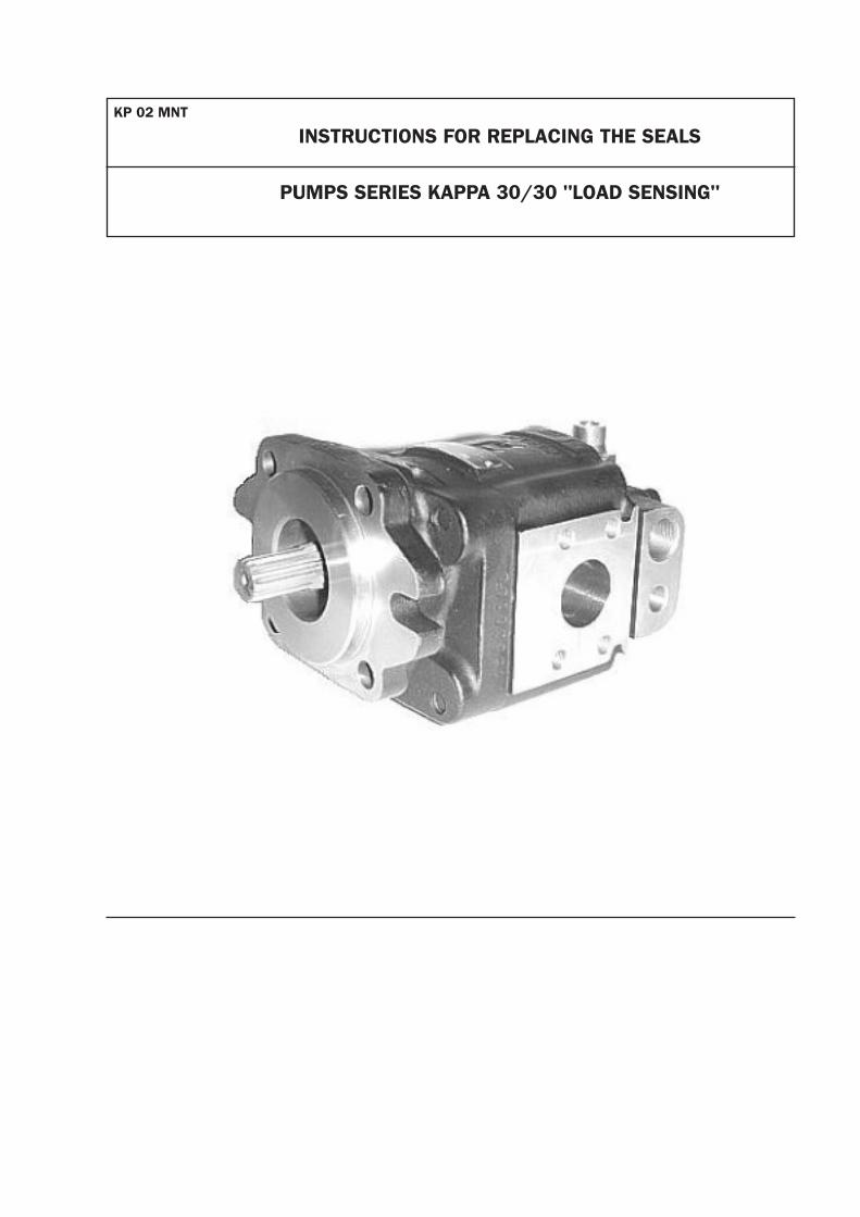
INSTRUCTIONS FOR REPLACING THE SEALS
PUMPS SERIES KAPPA 30/30 "LOAD SENSING"
5.00
21.80+0.07+0.02
26.00
14.00 15.00
18.5
3.2 1.6
1.6
1.6
R 2.50 2.00
M8
7
25.0
0
27.5
0 40.0
0
29.0
028
.00
12.5
0
0-0.10
19.
15
0+0.
10
24.00+0.20+0.10
25.00+0.20+0.10
5.50
==
15
.00
3.2 1.6
AM
NM
O40
0/04
99AM
NB
004
0/04
99
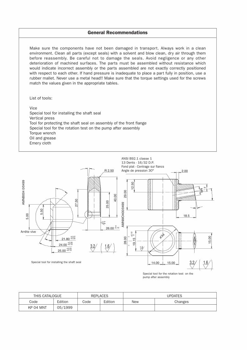
Special tool for installing the shaft seal
Special tool for the rotation test on thepump after assembly
ANSI B92.1 classe 113 Dents - 16/32 D.P.Fond plat - Centrage sur flancsAngle de pression 30°
Arrête vive
ø34
THIS CATALOGUE REPLACES UPDATES
Code Edition Code Edition New Changes
KP 04 MNT 05/1999
General Recommendations
Make sure the components have not been damaged in transpor t. Always work in a cleanenvironment. Clean all parts (except seals) with a solvent and blow clean, dry air through thembefore reassembly. Be careful not to damage the seals. Avoid negligence or any otherdeterioration of machined surfaces. The parts must be assembled without resistance whichwould indicate incorrect assembly or the parts assembled are not exactly correctly positionedwith respect to each other. If hand pressure is inadequate to place a part fully in position, use arubber mallet. Never use a metal head!! Make sure that the torque settings used for the screwsmatch the values given in the appropriate tables.
List of tools:
ViceSpecial tool for installing the shaft sealVertical pressTool for protecting the shaft seal on assembly of the front flangeSpecial tool for the rotation test on the pump after assemblyTorque wrenchOil and greaseEmery cloth
1
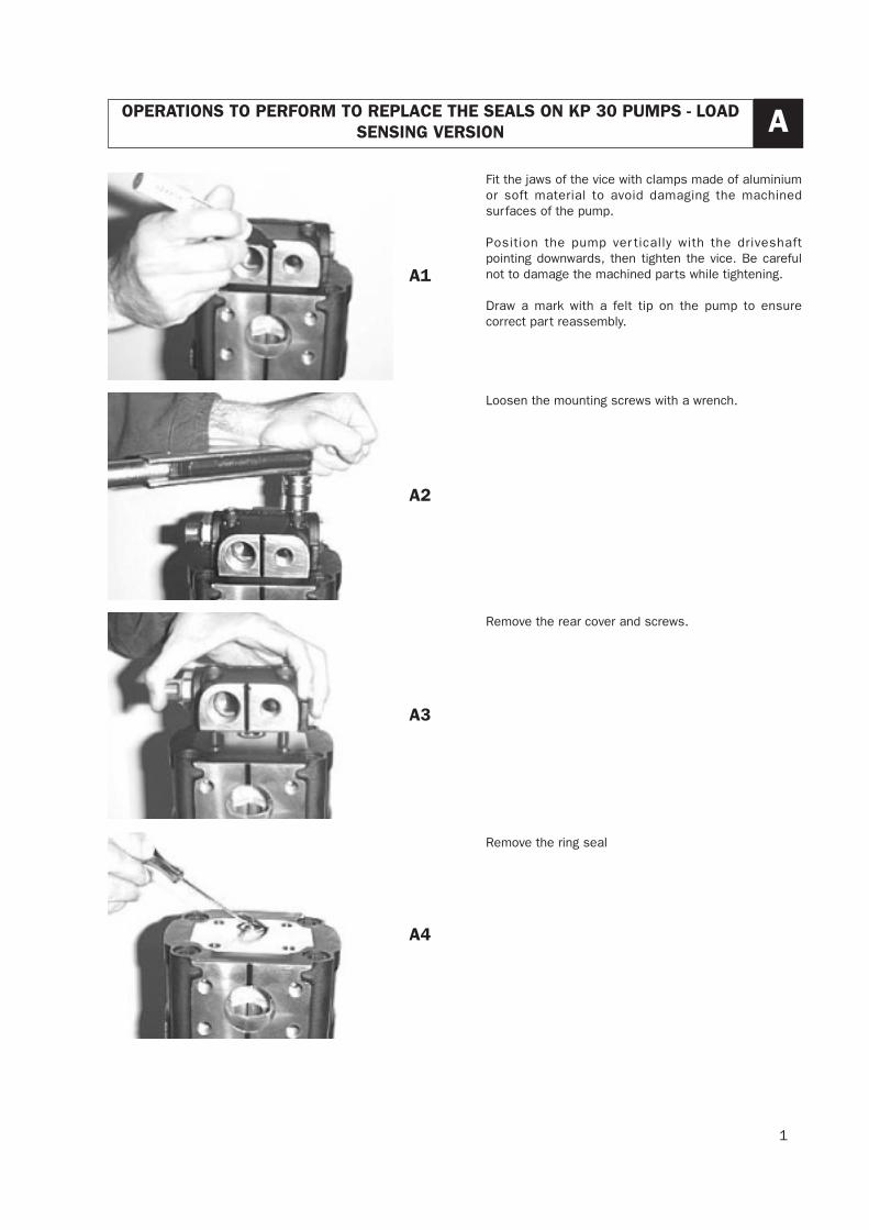
OPERATIONS TO PERFORM TO REPLACE THE SEALS ON KP 30 PUMPS - LOADSENSING VERSION A
Fit the jaws of the vice with clamps made of aluminiumor soft material to avoid damaging the machinedsurfaces of the pump.
Position the pump ver tically with the driveshaftpointing downwards, then tighten the vice. Be carefulnot to damage the machined parts while tightening.
Draw a mark with a felt tip on the pump to ensurecorrect part reassembly.
Loosen the mounting screws with a wrench.
Remove the rear cover and screws.
Remove the ring seal
A1
A2
A3
A4
2
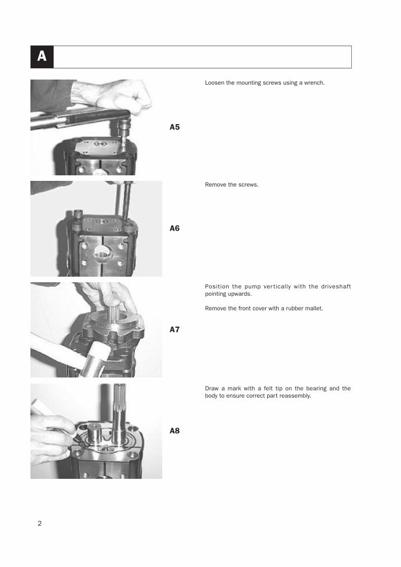
A
Loosen the mounting screws using a wrench.
Remove the screws.
Position the pump ver tically with the driveshaftpointing upwards.
Remove the front cover with a rubber mallet.
Draw a mark with a felt tip on the bearing and thebody to ensure correct part reassembly.
A5
A6
A7
A8
3
A
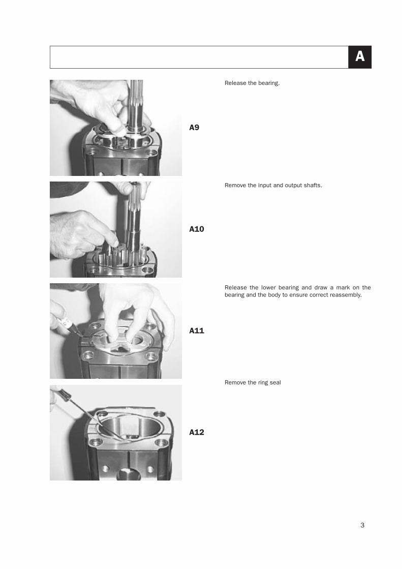
Release the bearing.
Remove the input and output shafts.
Release the lower bearing and draw a mark on thebearing and the body to ensure correct reassembly.
Remove the ring seal
A9
A10
A11
A12
4
A
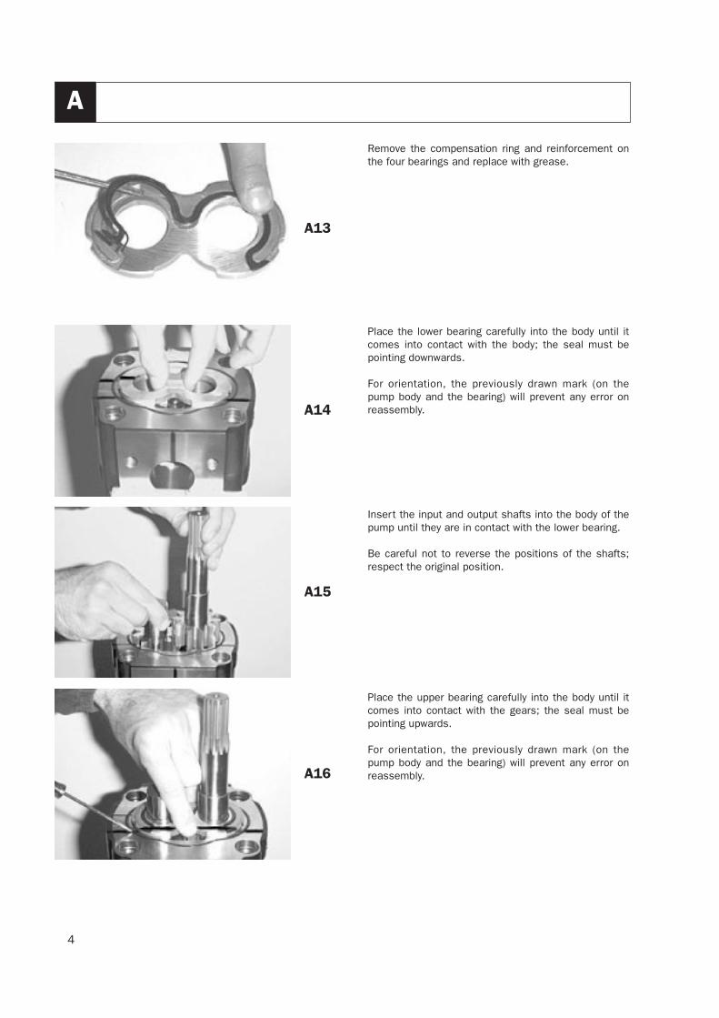
Remove the compensation ring and reinforcement onthe four bearings and replace with grease.
Place the lower bearing carefully into the body until itcomes into contact with the body; the seal must bepointing downwards.
For orientation, the previously drawn mark (on thepump body and the bearing) will prevent any error onreassembly.
Insert the input and output shafts into the body of thepump until they are in contact with the lower bearing.
Be careful not to reverse the positions of the shafts;respect the original position.
Place the upper bearing carefully into the body until itcomes into contact with the gears; the seal must bepointing upwards.
For orientation, the previously drawn mark (on thepump body and the bearing) will prevent any error onreassembly.
A13
A14
A15
A16
5
A
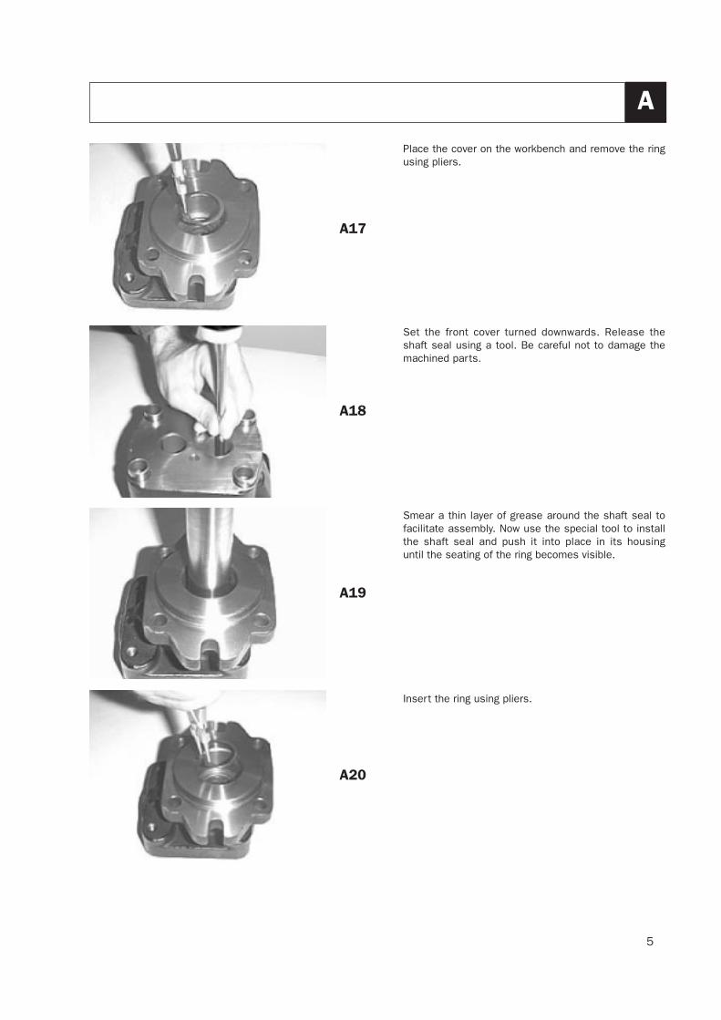
Place the cover on the workbench and remove the ringusing pliers.
Set the front cover turned downwards. Release theshaft seal using a tool. Be careful not to damage themachined parts.
Smear a thin layer of grease around the shaft seal tofacilitate assembly. Now use the special tool to installthe shaft seal and push it into place in its housinguntil the seating of the ring becomes visible.
Insert the ring using pliers.
A17
A18
A19
A20
6
A
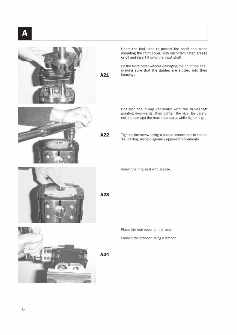
Coast the tool used to protect the shaft seal whenmounting the front cover, with uncontaminated greaseor oil and insert it onto the input shaft.
Fit the front cover without damaging the lip of the seal,making sure that the guides are slotted into theirhousings.
Position the pump ver tically with the driveshaftpointing downwards, then tighten the vice. Be carefulnot the damage the machined parts while tightening.
Tighten the screw using a torque wrench set to torque14 (daNm), using diagonally opposed movements.
Insert the ring seal with grease.
Place the rear cover on the vice.
Loosen the stopper using a wrench.
A21
A22
A23
A24
7
A
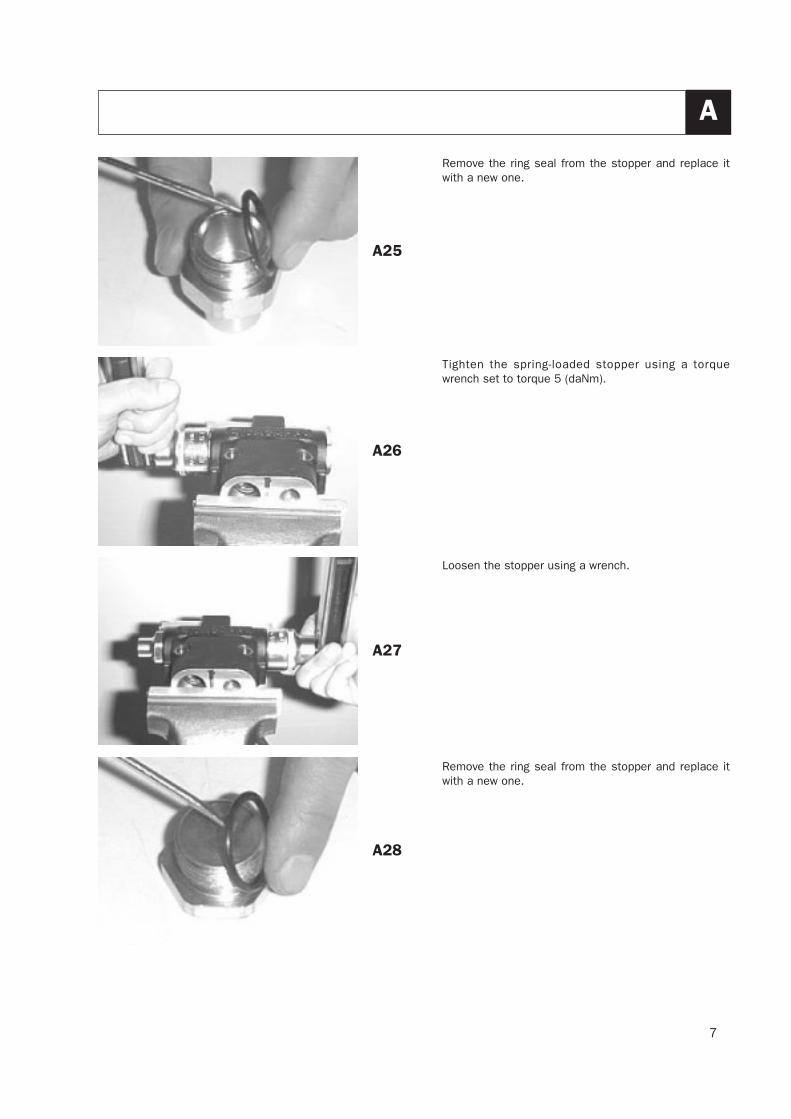
Remove the ring seal from the stopper and replace itwith a new one.
Tighten the spring-loaded stopper using a torquewrench set to torque 5 (daNm).
Loosen the stopper using a wrench.
Remove the ring seal from the stopper and replace itwith a new one.
A25
A26
A27
A28
8
A
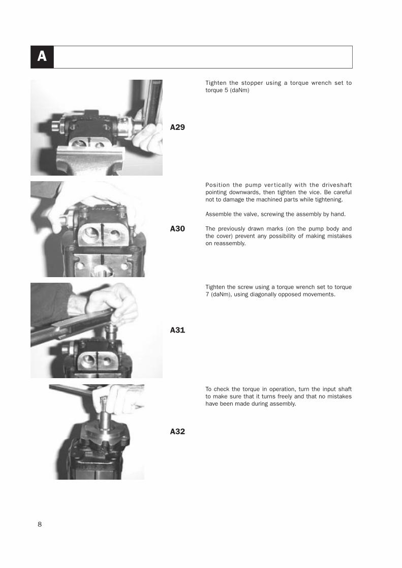
Tighten the stopper using a torque wrench set totorque 5 (daNm)
Position the pump ver tically with the driveshaftpointing downwards, then tighten the vice. Be carefulnot to damage the machined parts while tightening.
Assemble the valve, screwing the assembly by hand.
The previously drawn marks (on the pump body andthe cover) prevent any possibility of making mistakeson reassembly.
Tighten the screw using a torque wrench set to torque7 (daNm), using diagonally opposed movements.
To check the torque in operation, turn the input shaftto make sure that it turns freely and that no mistakeshave been made during assembly.
A29
A30
A31
A32

9
Our policy is to work towards constant product improvement; for this reason product characteristics are subject tochange without prior notification.
10
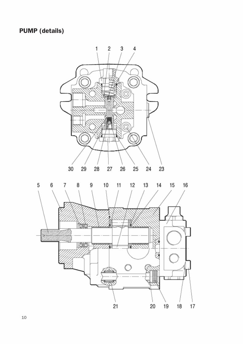
PUMP (details)
11
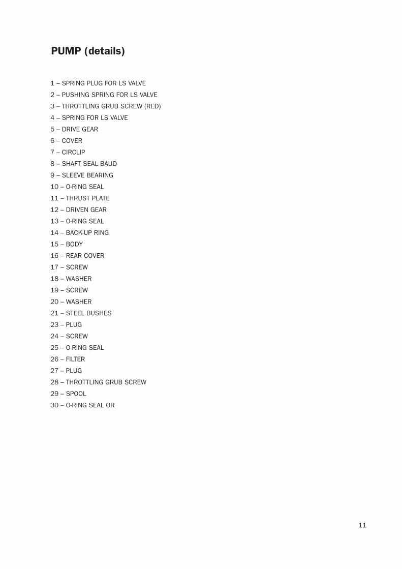
PUMP (details)
1 – SPRING PLUG FOR LS VALVE
2 – PUSHING SPRING FOR LS VALVE
3 – THROTTLING GRUB SCREW (RED)
4 – SPRING FOR LS VALVE
5 – DRIVE GEAR
6 – COVER
7 – CIRCLIP
8 – SHAFT SEAL BAUD
9 – SLEEVE BEARING
10 – O-RING SEAL
11 – THRUST PLATE
12 – DRIVEN GEAR
13 – O-RING SEAL
14 – BACK-UP RING
15 – BODY
16 – REAR COVER
17 – SCREW
18 – WASHER
19 – SCREW
20 – WASHER
21 – STEEL BUSHES
23 – PLUG
24 – SCREW
25 – O-RING SEAL
26 – FILTER
27 – PLUG
28 – THROTTLING GRUB SCREW
29 – SPOOL
30 – O-RING SEAL OR

12

DISMANTLING THE MAIN HYDRAULIC PUMP
70-3-47 EN
20 / 12 / 2007

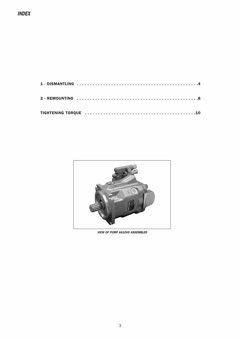
VIEW OF PUMP AA10VO ASSEMBLED
3
INDEX
1 - DISMANTLING . . . . . . . . . . . . . . . . . . . . . . . . . . . . . . . . . . . . . . . . . . . . . .4
2 - REMOUNTING . . . . . . . . . . . . . . . . . . . . . . . . . . . . . . . . . . . . . . . . . . . . . .8
TIGHTENING TORQUE . . . . . . . . . . . . . . . . . . . . . . . . . . . . . . . . . . . . . . . . . .10
4
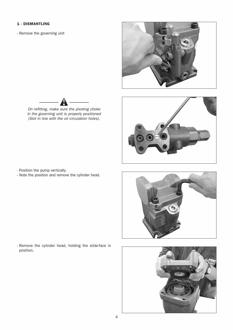
1 - DISMANTLING
- Remove the governing unit
On refitting, make sure the pivoting choke in the governing unit is properly positioned (Slot in line with the oil circulation holes).
- Position the pump vertically.- Note the position and remove the cylinder head.
- Remove the cylinder head, holding the slide-face inposition.
5
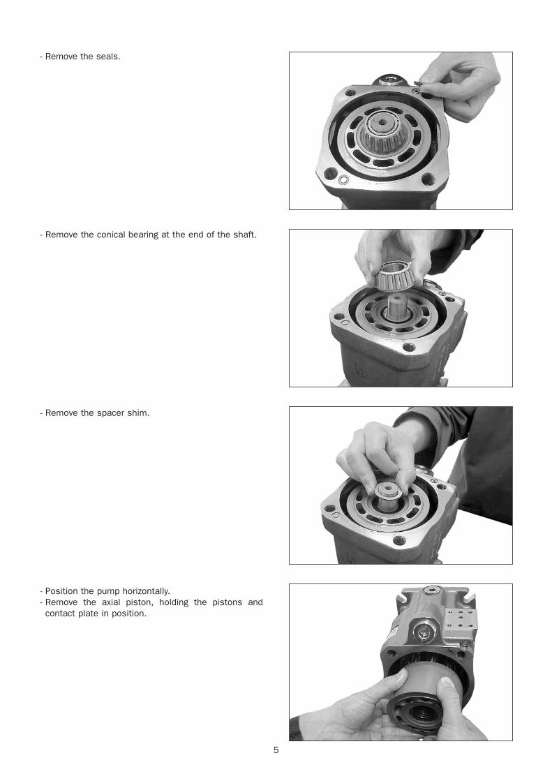
- Remove the seals.
- Remove the conical bearing at the end of the shaft.
- Remove the spacer shim.
- Position the pump horizontally.- Remove the axial piston, holding the pistons andcontact plate in position.
6
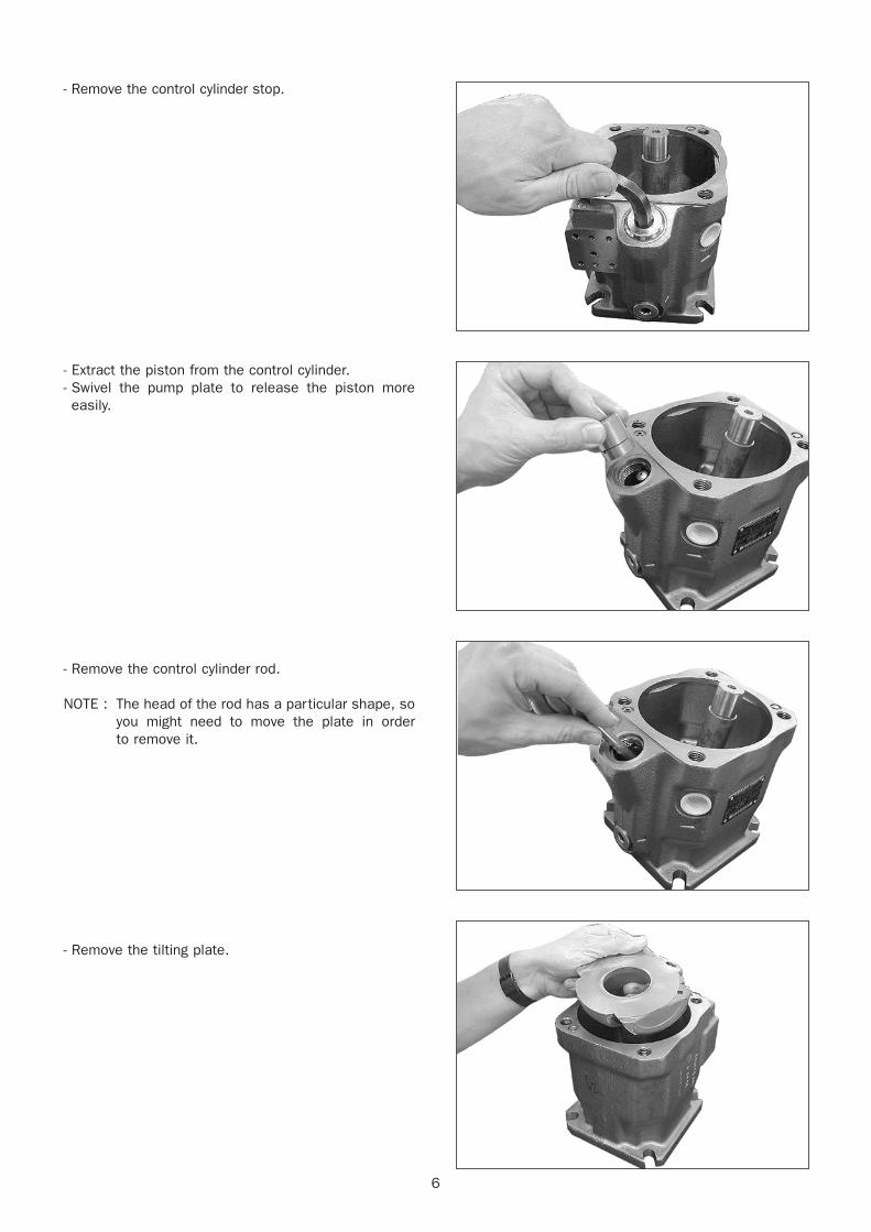
- Remove the control cylinder stop.
- Extract the piston from the control cylinder.- Swivel the pump plate to release the piston moreeasily.
- Remove the control cylinder rod.
NOTE : The head of the rod has a particular shape, soyou might need to move the plate in order to remove it.
- Remove the tilting plate.
7
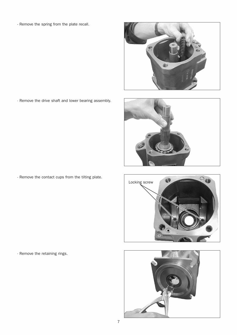
- Remove the spring from the plate recall.
- Remove the drive shaft and lower bearing assembly.
- Remove the contact cups from the tilting plate.
- Remove the retaining rings.
Locking screw
8
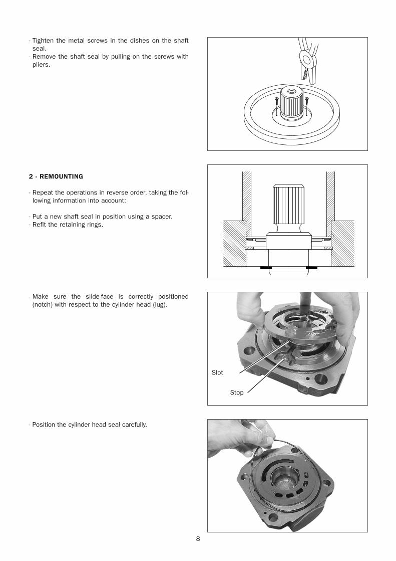
- Tighten the metal screws in the dishes on the shaftseal.
- Remove the shaft seal by pulling on the screws withpliers.
2 - REMOUNTING
- Repeat the operations in reverse order, taking the fol-lowing information into account:
- Put a new shaft seal in position using a spacer.- Refit the retaining rings.
- Make sure the slide-face is correctly positioned(notch) with respect to the cylinder head (lug).
- Position the cylinder head seal carefully.
Stop
Slot
9
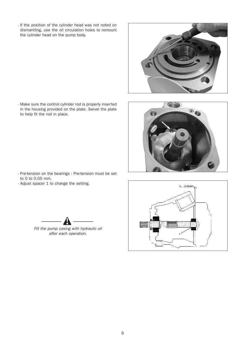
- If the position of the cylinder head was not noted ondismantling, use the oil circulation holes to remountthe cylinder head on the pump body.
- Make sure the control cylinder rod is properly insertedin the housing provided on the plate. Swivel the plateto help fit the rod in place.
- Pre-tension on the bearings : Pre-tension must be setto 0 to 0.05 mm.
- Adjust spacer 1 to change the setting.
Fill the pump casing with hydraulic oil after each operation.
10
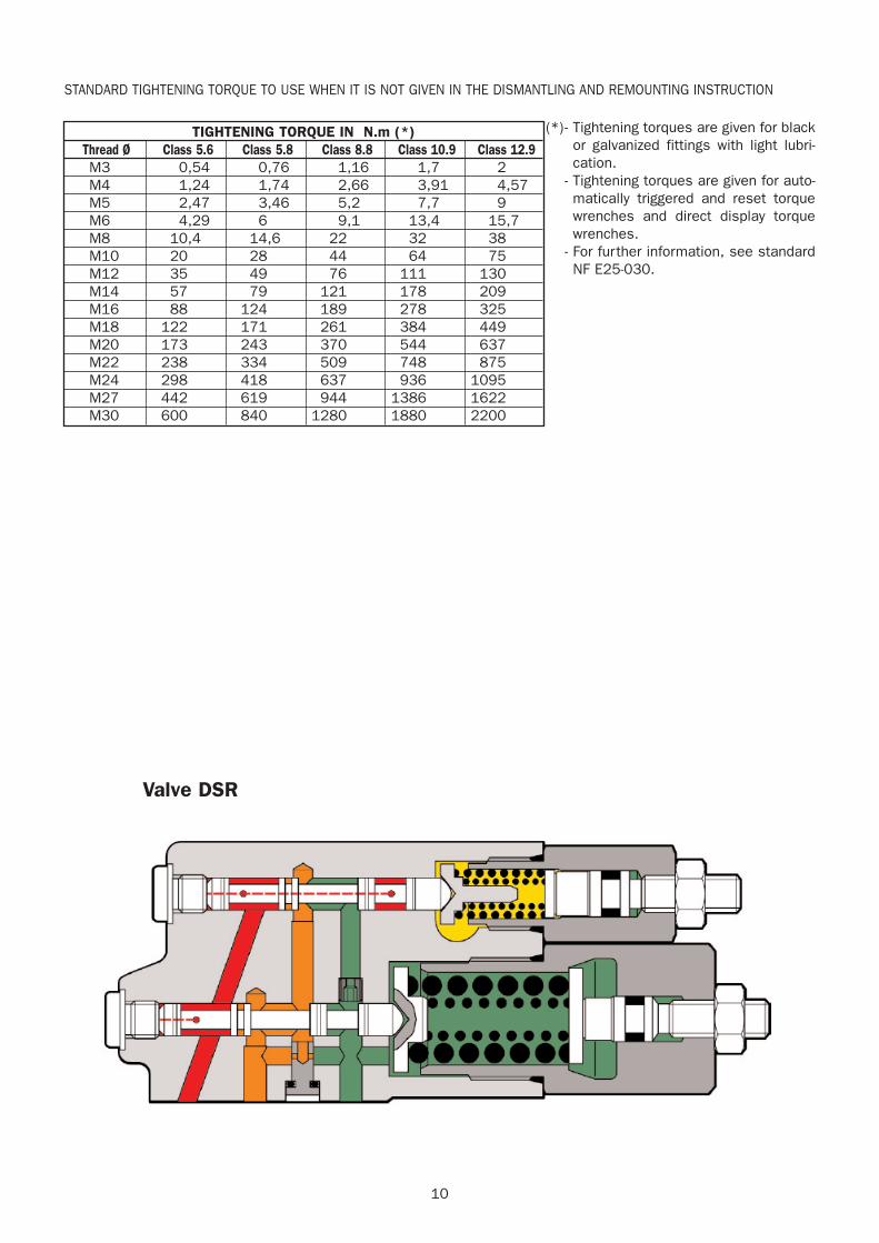
TIGHTENING TORQUE IN N.m (*)Thread Ø Class 5.6 Class 5.8 Class 8.8 Class 10.9 Class 12.9M3 0,54 0,76 1,16 1,7 2M4 1,24 1,74 2,66 3,91 4,57M5 2,47 3,46 5,2 7,7 9M6 4,29 6 9,1 13,4 15,7M8 10,4 14,6 22 32 38M10 20 28 44 64 75M12 35 49 76 111 130M14 57 79 121 178 209M16 88 124 189 278 325M18 122 171 261 384 449M20 173 243 370 544 637M22 238 334 509 748 875M24 298 418 637 936 1095M27 442 619 944 1386 1622M30 600 840 1280 1880 2200
STANDARD TIGHTENING TORQUE TO USE WHEN IT IS NOT GIVEN IN THE DISMANTLING AND REMOUNTING INSTRUCTION
(*)- Tightening torques are given for blackor galvanized fittings with light lubri-cation.
- Tightening torques are given for auto-matically triggered and reset torquewrenches and direct display torquewrenches.
- For further information, see standardNF E25-030.
Valve DSR

12
DISTRIBUTOR DISASSEMBLY
70-3-54 EN
30 / 09 / 2003

3
INDEX
DISTRIBUTOR SX 14 : GENERALITY
1 - INTRODUCTION . . . . . . . . . . . . . . . . . . . . . . . . . . . . . . . . . . . . . . . . . . . . .41.1 Preface . . . . . . . . . . . . . . . . . . . . . . . . . . . . . . . . . . . . . . . . . . . . . . . . . .41.2 Safety instructions . . . . . . . . . . . . . . . . . . . . . . . . . . . . . . . . . . . . . . . . . . . . . . . . . . . . . . . . . . . . . . . . . . . . . . . .44
2 - TROUBLE-SHOOTING . . . . . . . . . . . . . . . . . . . . . . . . . . . . . . . . . . . . . . . . . .5
3 - BASIC RULES . . . . . . . . . . . . . . . . . . . . . . . . . . . . . . . . . . . . . . . . . . . . . .73.1 General rules regarding connecting the distribution block . . . . . . . . . . . . . .7
4 - REMOVING / REMOUNTING THE SX 14 BLOC . . . . . . . . . . . . . . . . . . . . . . .74.1 General Recommendations . . . . . . . . . . . . . . . . . . . . . . . . . . . . . . . . . . . .74.2 Removing the SX 14 block . . . . . . . . . . . . . . . . . . . . . . . . . . . . . . . . . . . .74.3 Remounting the SX 14 block . . . . . . . . . . . . . . . . . . . . . . . . . . . . . . . . . . .7
5 - SX BLOCK REPAIR PROCEDURES . . . . . . . . . . . . . . . . . . . . . . . . . . . . . . . .85.1 Changing the LS limiter . . . . . . . . . . . . . . . . . . . . . . . . . . . . . . . . . . . . . . .85.2 Changing the flow rate governor . . . . . . . . . . . . . . . . . . . . . . . . . . . . . . . .85.3 Disassembling the flow divider governing subassembly . . . . . . . . . . . . . . . .85.4 Disassembling the sweepingvalve . . . . . . . . . . . . . . . . . . . . . . . . . . . . . .105.5 Changing the secondary pressure relief valve . . . . . . . . . . . . . . . . . . . . . .105.6 Disassembling a slide valve . . . . . . . . . . . . . . . . . . . . . . . . . . . . . . . . . . .115.7 Disassembling / assembly of the distribution block . . . . . . . . . . . . . . . . . .12
6 - SPECIFIC TIGHTENING TORQUE
6.1 MLT 845 -120 LSU / MLT 940 L -120 LSU . . . . . . . . . . . . . . . . . . . . . . . .14
4
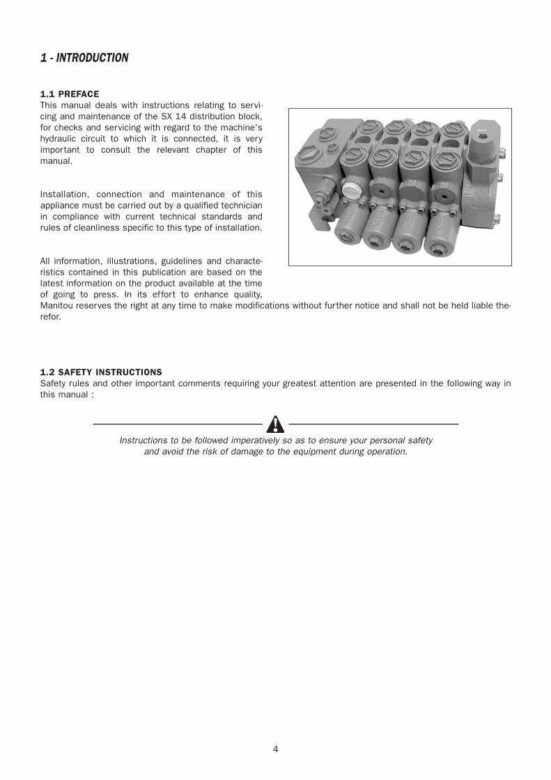
1 - INTRODUCTION
1.1 PREFACEThis manual deals with instructions relating to servi-cing and maintenance of the SX 14 distribution block,for checks and servicing with regard to the machine'shydraulic circuit to which it is connected, it is veryimportant to consult the relevant chapter of thismanual.
Installation, connection and maintenance of thisappliance must be carried out by a qualified technicianin compliance with current technical standards andrules of cleanliness specific to this type of installation.
All information, illustrations, guidelines and characte-ristics contained in this publication are based on thelatest information on the product available at the timeof going to press. In its effort to enhance quality,Manitou reserves the right at any time to make modifications without further notice and shall not be held liable the-refor.
1.2 SAFETY INSTRUCTIONSSafety rules and other important comments requiring your greatest attention are presented in the following way inthis manual :
Instructions to be followed imperatively so as to ensure your personal safetyand avoid the risk of damage to the equipment during operation.
5
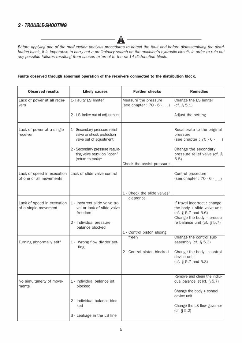
Observed results Likely causes Further checks Remedies
Lack of power at all recei-vers
Lack of power at a singlereceiver
Lack of speed in executionof one or all movements
Lack of speed in executionof a single movement
Turning abnormally stiff
No simultaneity of move-ments
1- Faulty LS limiter
2 - LS limiter out of adjustment
1 - Secondary pressure reliefvalve or shock protectionvalve out of adjustment
2 - Secondary pressure regula-ting valve stuck on "open"(return to tank)*
Lack of slide valve control
1 - Incorrect slide valve tra-vel or lack of slide valvefreedom
2 - Individual pressurebalance blocked
1 - Wrong flow divider set-ting
1 - Individual balance jetblocked
2 - Individual balance bloc-ked
3 - Leakage in the LS line
Measure the pressure(see chapter : 70 - 6 - _ _)
Check the assist pressure
1 - Check the slide valves'clearance
1 - Control piston slidingfreely
2 - Control piston blocked
Change the LS limiter (cf. § 5.1)
Adjust the setting
Recalibrate to the originalpressure(see chapter : 70 - 6 - _ _)
Change the secondarypressure relief valve (cf. §5.5)
Control procedure(see chapter : 70 - 6 - _ _)
If travel incorrect : changethe body + slide valve unit(cf. § 5.7 and 5.6) Change the body + pressu-re balance unit (cf. § 5.7)
Change the control sub-assembly (cf. § 5.3)
Change the body + controldevice unit(cf. § 5.7 and 5.3)
Remove and clean the indivi-dual balance jet (cf. § 5.7)
Change the body + controldevice unit
Change the LS flow governor(cf. § 5.2)
2 - TROUBLE-SHOOTING
Before applying one of the malfunction analysis procedures to detect the fault and before disassembling the distri-bution block, it is imperative to carry out a preliminary search on the machine's hydraulic circuit, in order to rule outany possible failures resulting from causes external to the sx 14 distribution block.
Faults observed through abnormal operation of the receivers connected to the distribution block.
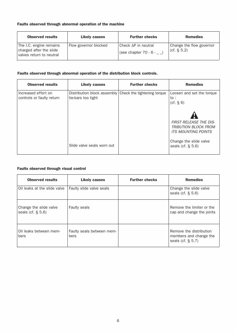
Increased effort oncontrols or faulty return
Loosen and set the torqueto :(cf. § 6)
FIRST RELEASE THE DIS-TRIBUTION BLOCK FROMITS MOUNTING POINTS
Change the slide valveseals (cf. § 5.6)
6
Observed results Likely causes Further checks Remedies
The I.C. engine remainscharged after the slidevalves return to neutral
Flow governor blocked Check ΔP in neutral
(see chapter 70 - 6 - _ _)
Change the flow governor(cf. § 5.2)
Observed results Likely causes Further checks Remedies
Distribution block assemblytie-bars too tight
Slide valve seals worn out
Check the tightening torque
Observed results Likely causes Further checks Remedies
Oil leaks at the slide valve
Change the slide valveseals (cf. § 5.6)
Oil leaks between mem-bers
Faulty slide valve seals
Faulty seals
Faulty seals between mem-bers
Change the slide valveseals (cf. § 5.6)
Remove the limiter or thecap and change the joints
Remove the distributionmembers and change theseals (cf. § 5.7)
Faults observed through abnormal operation of the machine
Faults observed through abnormal operation of the distribution block controls.
Faults observed through visual control
7
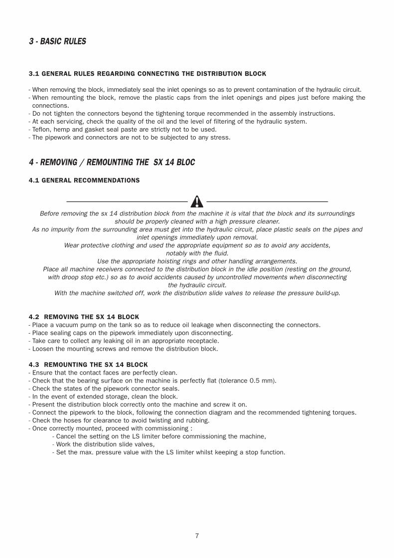
3 - BASIC RULES
3.1 GENERAL RULES REGARDING CONNECTING THE DISTRIBUTION BLOCK
- When removing the block, immediately seal the inlet openings so as to prevent contamination of the hydraulic circuit.- When remounting the block, remove the plastic caps from the inlet openings and pipes just before making theconnections.
- Do not tighten the connectors beyond the tightening torque recommended in the assembly instructions.- At each servicing, check the quality of the oil and the level of filtering of the hydraulic system.- Teflon, hemp and gasket seal paste are strictly not to be used.- The pipework and connectors are not to be subjected to any stress.
4 - REMOVING / REMOUNTING THE SX 14 BLOC
4.1 GENERAL RECOMMENDATIONS
Before removing the sx 14 distribution block from the machine it is vital that the block and its surroundingsshould be properly cleaned with a high pressure cleaner.
As no impurity from the surrounding area must get into the hydraulic circuit, place plastic seals on the pipes andinlet openings immediately upon removal.
Wear protective clothing and used the appropriate equipment so as to avoid any accidents, notably with the fluid.
Use the appropriate hoisting rings and other handling arrangements.Place all machine receivers connected to the distribution block in the idle position (resting on the ground,
with droop stop etc.) so as to avoid accidents caused by uncontrolled movements when disconnectingthe hydraulic circuit.
With the machine switched off, work the distribution slide valves to release the pressure build-up.
4.2 REMOVING THE SX 14 BLOCK- Place a vacuum pump on the tank so as to reduce oil leakage when disconnecting the connectors. - Place sealing caps on the pipework immediately upon disconnecting.- Take care to collect any leaking oil in an appropriate receptacle.- Loosen the mounting screws and remove the distribution block.
4.3 REMOUNTING THE SX 14 BLOCK- Ensure that the contact faces are perfectly clean.- Check that the bearing surface on the machine is perfectly flat (tolerance 0.5 mm).- Check the states of the pipework connector seals.- In the event of extended storage, clean the block.- Present the distribution block correctly onto the machine and screw it on.- Connect the pipework to the block, following the connection diagram and the recommended tightening torques.- Check the hoses for clearance to avoid twisting and rubbing.- Once correctly mounted, proceed with commissioning :
- Cancel the setting on the LS limiter before commissioning the machine,- Work the distribution slide valves,- Set the max. pressure value with the LS limiter whilst keeping a stop function.
8
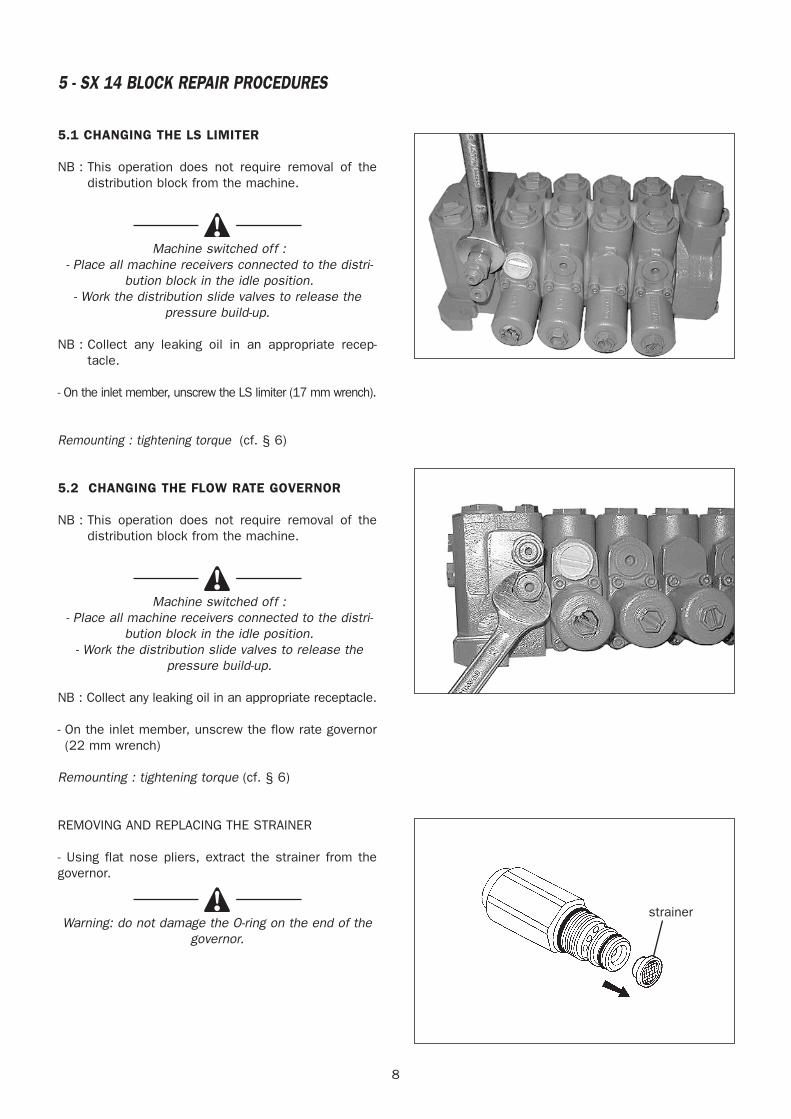
5 - SX 14 BLOCK REPAIR PROCEDURES
5.1 CHANGING THE LS LIMITER
NB : This operation does not require removal of thedistribution block from the machine.
Machine switched off :- Place all machine receivers connected to the distri-
bution block in the idle position.- Work the distribution slide valves to release the
pressure build-up.
NB : Collect any leaking oil in an appropriate recep-tacle.
- On the inlet member, unscrew the LS limiter (17 mm wrench).
Remounting : tightening torque (cf. § 6)
5.2 CHANGING THE FLOW RATE GOVERNOR
NB : This operation does not require removal of thedistribution block from the machine.
Machine switched off :- Place all machine receivers connected to the distri-
bution block in the idle position.- Work the distribution slide valves to release the
pressure build-up.
NB : Collect any leaking oil in an appropriate receptacle.
- On the inlet member, unscrew the flow rate governor(22 mm wrench)
Remounting : tightening torque (cf. § 6)
REMOVING AND REPLACING THE STRAINER
- Using flat nose pliers, extract the strainer from thegovernor.
Warning: do not damage the O-ring on the end of thegovernor.
strainer
9
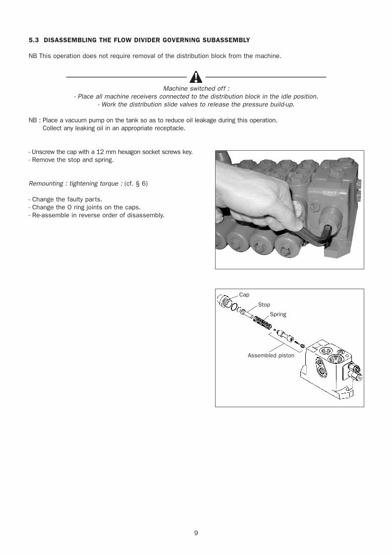
5.3 DISASSEMBLING THE FLOW DIVIDER GOVERNING SUBASSEMBLY
NB This operation does not require removal of the distribution block from the machine.
Machine switched off :- Place all machine receivers connected to the distribution block in the idle position.
- Work the distribution slide valves to release the pressure build-up.
NB : Place a vacuum pump on the tank so as to reduce oil leakage during this operation.Collect any leaking oil in an appropriate receptacle.
- Unscrew the cap with a 12 mm hexagon socket screws key.- Remove the stop and spring.
Remounting : tightening torque : (cf. § 6)
- Change the faulty parts.- Change the O ring joints on the caps.- Re-assemble in reverse order of disassembly.
Cap
Stop
Spring
Assembled piston
10
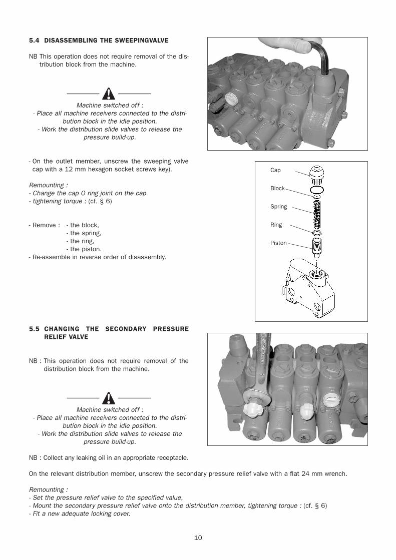
5.4 DISASSEMBLING THE SWEEPINGVALVE
NB This operation does not require removal of the dis-tribution block from the machine.
Machine switched off :- Place all machine receivers connected to the distri-
bution block in the idle position.- Work the distribution slide valves to release the
pressure build-up.
- On the outlet member, unscrew the sweeping valvecap with a 12 mm hexagon socket screws key).
Remounting :- Change the cap O ring joint on the cap- tightening torque : (cf. § 6)
- Remove : - the block,- the spring,- the ring,- the piston.
- Re-assemble in reverse order of disassembly.
5.5 CHANGING THE SECONDARY PRESSURERELIEF VALVE
NB : This operation does not require removal of thedistribution block from the machine.
Machine switched off :- Place all machine receivers connected to the distri-
bution block in the idle position.- Work the distribution slide valves to release the
pressure build-up.
NB : Collect any leaking oil in an appropriate receptacle.
On the relevant distribution member, unscrew the secondary pressure relief valve with a flat 24 mm wrench.
Remounting : - Set the pressure relief valve to the specified value,- Mount the secondary pressure relief valve onto the distribution member, tightening torque : (cf. § 6)- Fit a new adequate locking cover.
Cap
Block
Spring
Ring
Piston
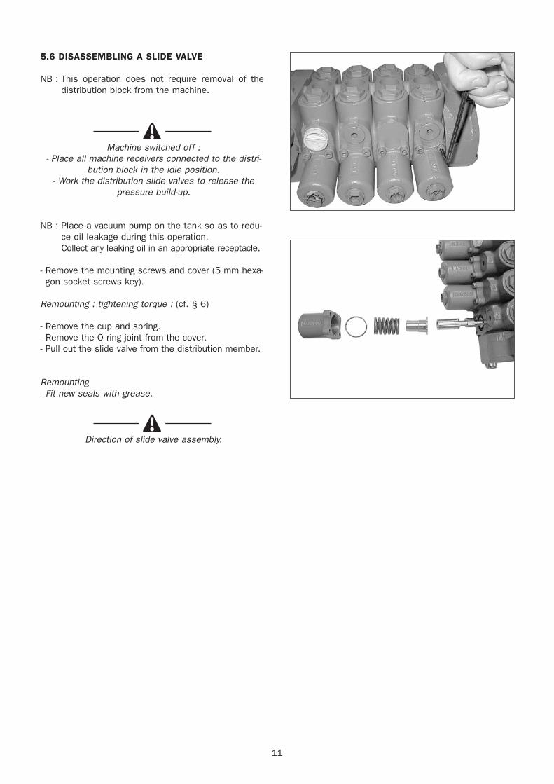
5.6 DISASSEMBLING A SLIDE VALVE
NB : This operation does not require removal of thedistribution block from the machine.
Machine switched off :- Place all machine receivers connected to the distri-
bution block in the idle position.- Work the distribution slide valves to release the
pressure build-up.
NB : Place a vacuum pump on the tank so as to redu-ce oil leakage during this operation.Collect any leaking oil in an appropriate receptacle.
- Remove the mounting screws and cover (5 mm hexa-gon socket screws key).
Remounting : tightening torque : (cf. § 6)
- Remove the cup and spring.- Remove the O ring joint from the cover.- Pull out the slide valve from the distribution member.
Remounting- Fit new seals with grease.
Direction of slide valve assembly.
11
12
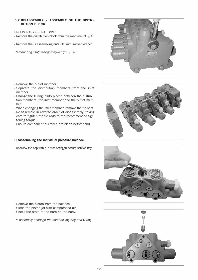
5.7 DISASSEMBLY / ASSEMBLY OF THE DISTRI-BUTION BLOCK
PRELIMINARY OPERATIONS :- Remove the distribution block from the machine (cf. § 4).
- Remove the 3 assembling nuts (13 mm socket wrench).
Remounting : tightening torque : (cf. § 6)
- Remove the outlet member.- Separate the distribution members from the inletmember.
- Change the O ring joints placed between the distribu-tion members, the inlet member and the outlet mem-ber.
- When changing the inlet member, remove the tie-bars.- Re-assemble in reverse order of disassembly, takingcare to tighten the tie rods to the recommended tigh-tening torque.
- Ensure component surfaces are clean beforehand.
Disassembling the individual pressure balance
- Unscrew the cap with a 7 mm hexagon socket screws key.
- Remove the piston from the balance.- Clean the piston jet with compressed air.- Check the state of the bore on the body.
Re-assembly : change the cap backing ring and O ring.
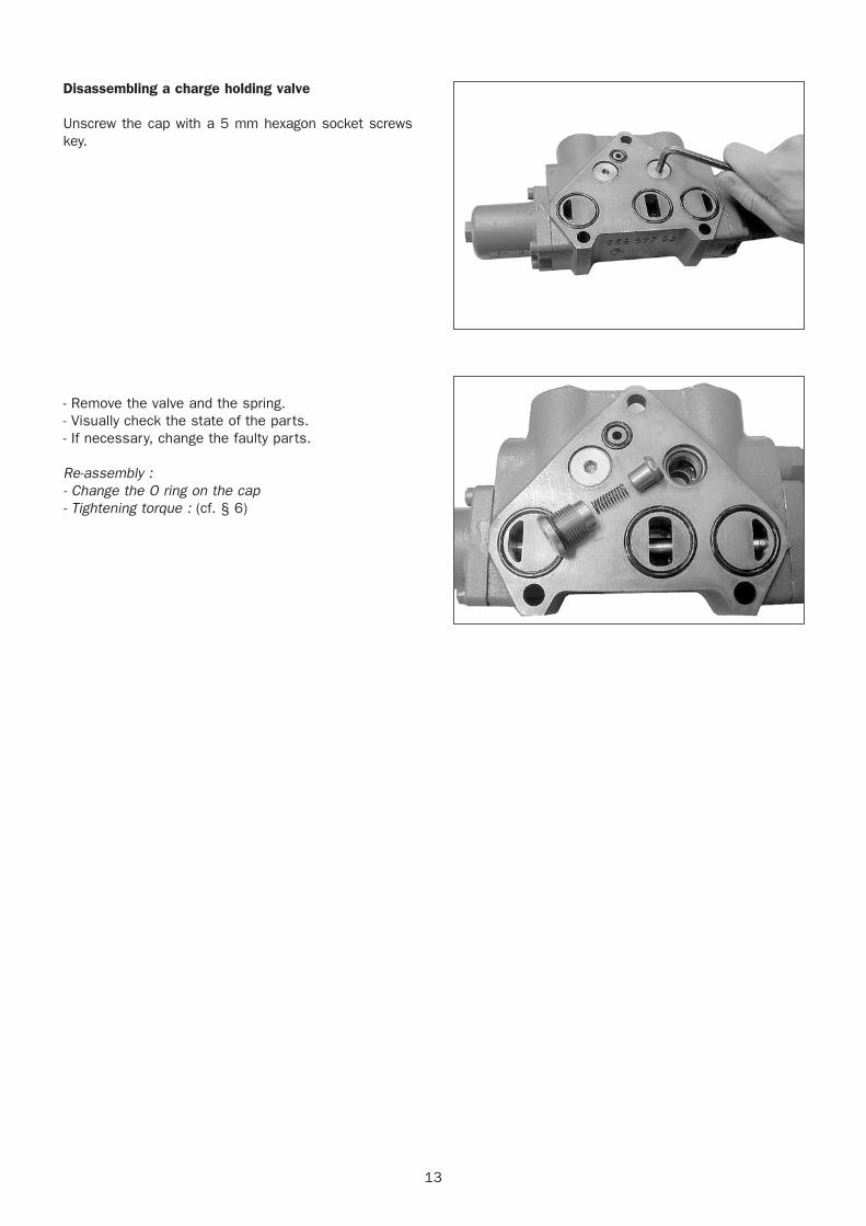
Disassembling a charge holding valve
Unscrew the cap with a 5 mm hexagon socket screwskey.
- Remove the valve and the spring.- Visually check the state of the parts.- If necessary, change the faulty parts.
Re-assembly : - Change the O ring on the cap- Tightening torque : (cf. § 6)
13
14
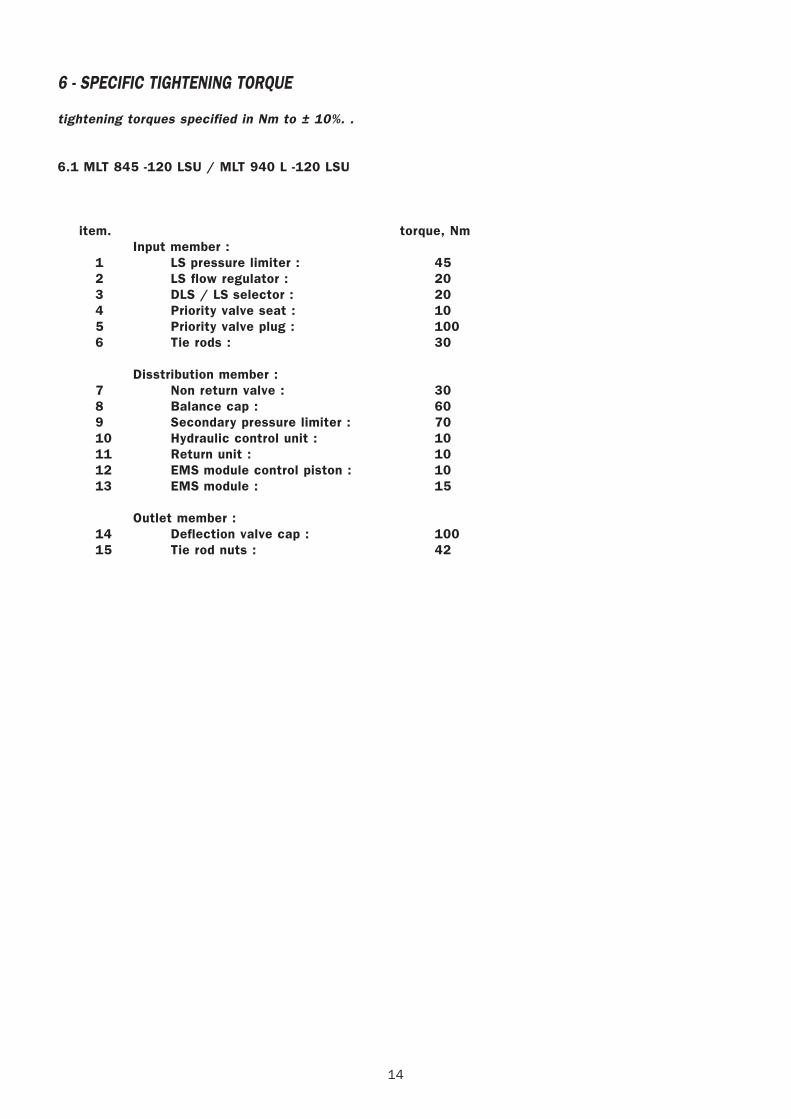
6 - SPECIFIC TIGHTENING TORQUE
tightening torques specified in Nm to ± 10%. .
6.1 MLT 845 -120 LSU / MLT 940 L -120 LSU
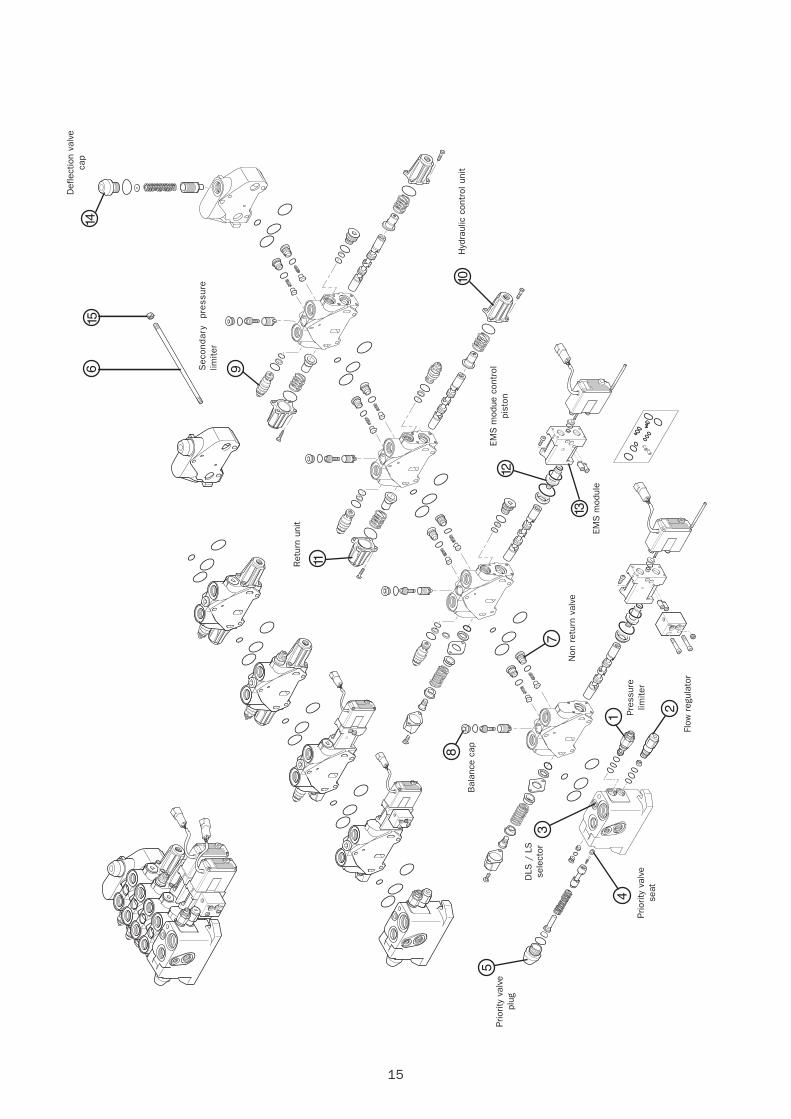
item. torque, NmInput member :
1 LS pressure limiter : 452 LS flow regulator : 203 DLS / LS selector : 204 Priority valve seat : 105 Priority valve plug : 1006 Tie rods : 30
Disstribution member :7 Non return valve : 308 Balance cap : 609 Secondary pressure limiter : 7010 Hydraulic control unit : 1011 Return unit : 1012 EMS module control piston : 1013 EMS module : 15
Outlet member :14 Deflection valve cap : 10015 Tie rod nuts : 42
15
6 9
11
8
7
1
2
3
4
5
12
13
10
1514
Def
lect
ion
valv
eca
p
Sec
onda
ry
pres
sure
limite
r
Ret
urn
unit
Hyd
raul
ic c
ontr
ol u
nit
EMS
mod
ue c
ontr
olpi
ston
EMS
mod
ule
Non
ret
urn
valv
e
Bal
ance
cap
Flow
reg
ulat
or
Pres
sure
limite
r
DLS
/ L
Sse
lect
or
Prio
rity
valv
ese
at
Prio
rity
valv
epl
ug

16
22 / 10 / 2003
CYLINDERS DISASSEMBLY
70-3-80-M92 EN

3
CONTENTS
A - REMOVAL AND REASSEMBLY OF THE COMPLETE STEM .......................4
B - REMOVAL AND REASSEMBLY OF THE PISTON ANDLOCKING RING ............................................................................. 6
C - REMOVAL AND REASSEMBLY OF THE PISTON SEALS AND RING.......................................................................... 8
D - REMOVAL AND REASSEMBLY OF THE LOCKING RING SEALS AND RING ........................................................................................ 9
E - APPLICATION OF THE THREAD LOCKING MATERIAL ............................10
F -SPECIAL OUTER TELESCOPE CYLINDER DISASSEMBLY MT 1740 PROCEDUREFOLLOW-UP .................................................................................................... 11
G - CYLINDERS DRAWINGS.............................................................................. ..22
4
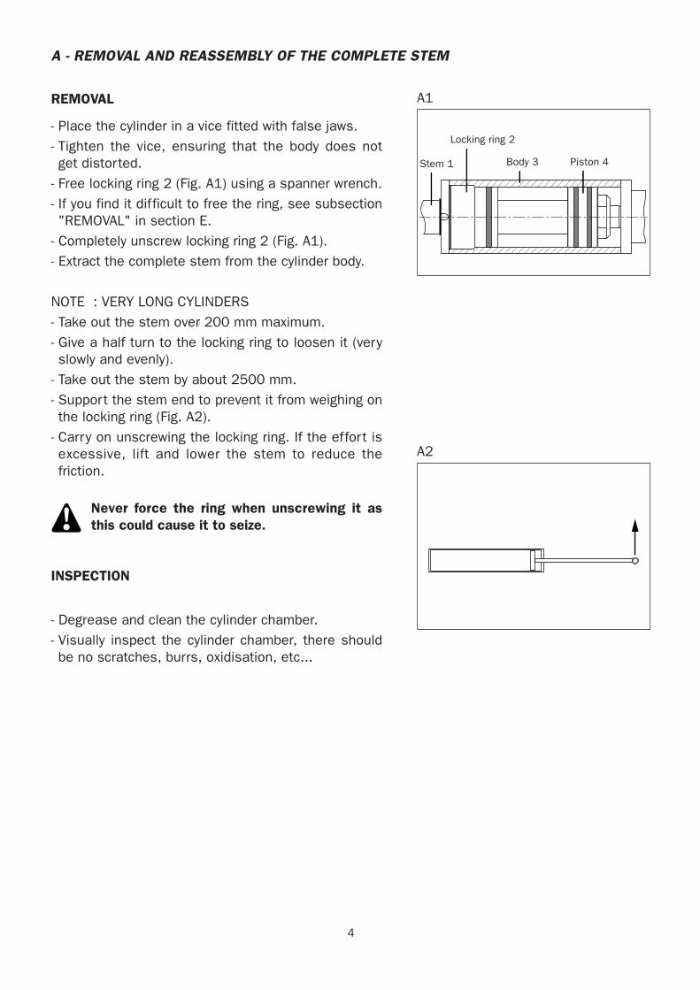
A - REMOVAL AND REASSEMBLY OF THE COMPLETE STEM
REMOVAL
- Place the cylinder in a vice fitted with false jaws.- Tighten the vice, ensuring that the body does notget distorted.
- Free locking ring 2 (Fig. A1) using a spanner wrench.- If you find it difficult to free the ring, see subsection"REMOVAL" in section E.
- Completely unscrew locking ring 2 (Fig. A1).- Extract the complete stem from the cylinder body.
NOTE : VERY LONG CYLINDERS- Take out the stem over 200 mm maximum.- Give a half turn to the locking ring to loosen it (veryslowly and evenly).
- Take out the stem by about 2500 mm.- Support the stem end to prevent it from weighing onthe locking ring (Fig. A2).
- Carry on unscrewing the locking ring. If the effort isexcessive, lift and lower the stem to reduce thefriction.
Never force the ring when unscrewing it asthis could cause it to seize.
INSPECTION
- Degrease and clean the cylinder chamber.- Visually inspect the cylinder chamber, there shouldbe no scratches, burrs, oxidisation, etc...
Tige 1 Corps 3
Bague de fermeture 2
Piston 4
A1
A2
Stem 1
Locking ring 2
Body 3 Piston 4
5
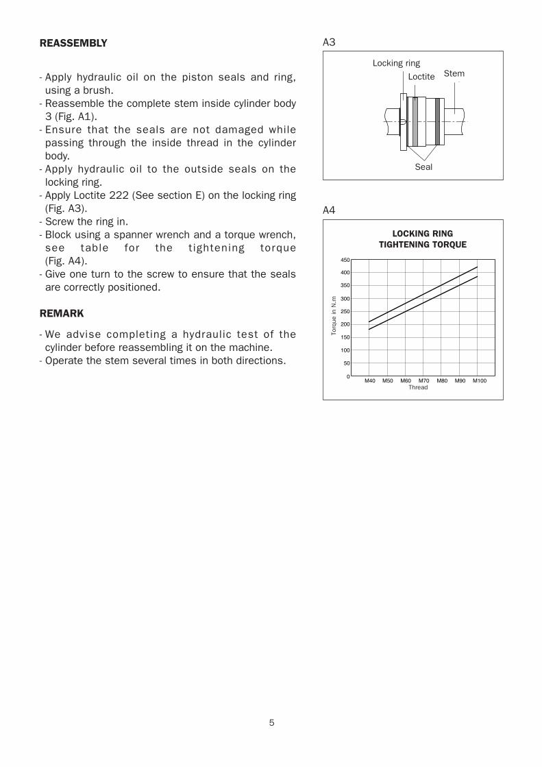
REASSEMBLY
- Apply hydraulic oil on the piston seals and ring,using a brush.
- Reassemble the complete stem inside cylinder body3 (Fig. A1).
- Ensure that the seals are not damaged whilepassing through the inside thread in the cylinderbody.
- Apply hydraulic oil to the outside seals on thelocking ring.
- Apply Loctite 222 (See section E) on the locking ring(Fig. A3).
- Screw the ring in.- Block using a spanner wrench and a torque wrench,see table for the t ightening torque (Fig. A4).
- Give one turn to the screw to ensure that the sealsare correctly positioned.
REMARK
- We advise completing a hydraulic test of thecylinder before reassembling it on the machine.
- Operate the stem several times in both directions.
Bague de fermeture
Frein filet Tige
Joint
A3
M40
450
COUPLE DE SERRAGE BAGUE DE FERMETURE
400
350
300
250
200
150
100
50
0M50 M60
Filetage
Cou
ple
en N
.m
M70 M80 M90 M100
A4
Locking ring
Loctite Stem
Seal
LOCKING RINGTIGHTENING TORQUE
Thread
Torq
ue in
N.m
6
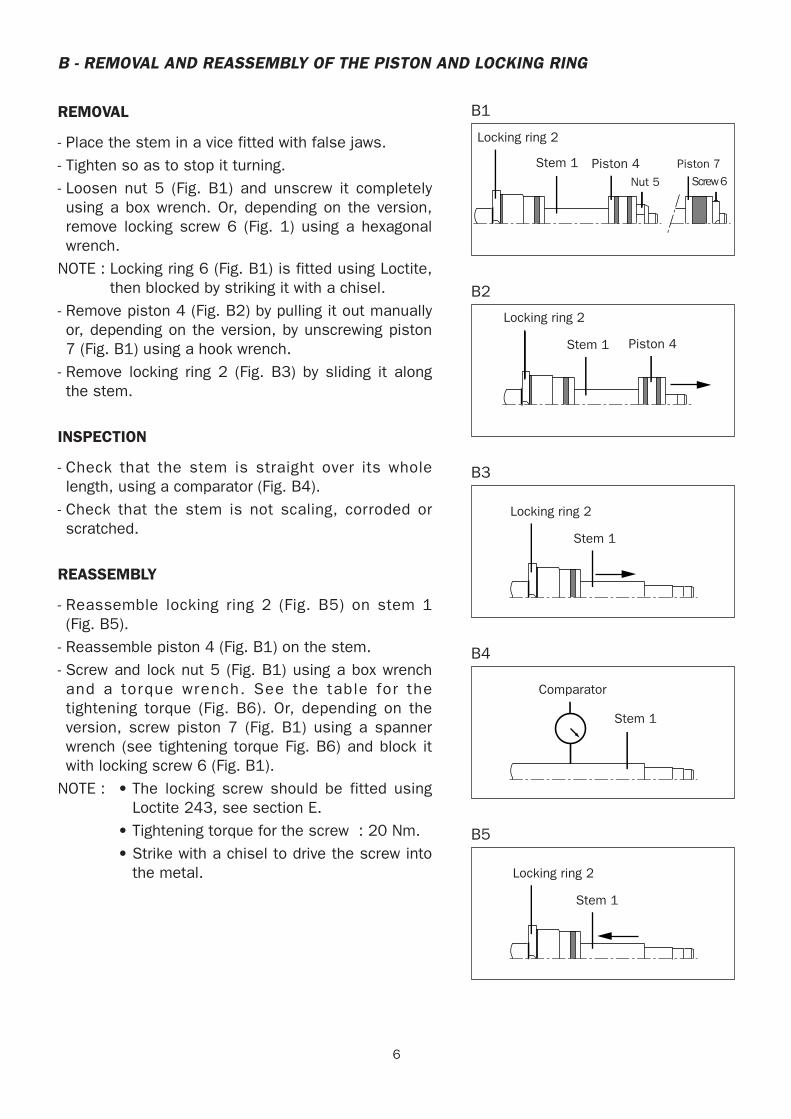
B - REMOVAL AND REASSEMBLY OF THE PISTON AND LOCKING RING
REMOVAL
- Place the stem in a vice fitted with false jaws.- Tighten so as to stop it turning.- Loosen nut 5 (Fig. B1) and unscrew it completelyusing a box wrench. Or, depending on the version,remove locking screw 6 (Fig. 1) using a hexagonalwrench.
NOTE : Locking ring 6 (Fig. B1) is fitted using Loctite,then blocked by striking it with a chisel.
- Remove piston 4 (Fig. B2) by pulling it out manuallyor, depending on the version, by unscrewing piston7 (Fig. B1) using a hook wrench.
- Remove locking ring 2 (Fig. B3) by sliding it alongthe stem.
INSPECTION
- Check that the stem is straight over its wholelength, using a comparator (Fig. B4).
- Check that the stem is not scaling, corroded orscratched.
REASSEMBLY
- Reassemble locking ring 2 (Fig. B5) on stem 1 (Fig. B5).
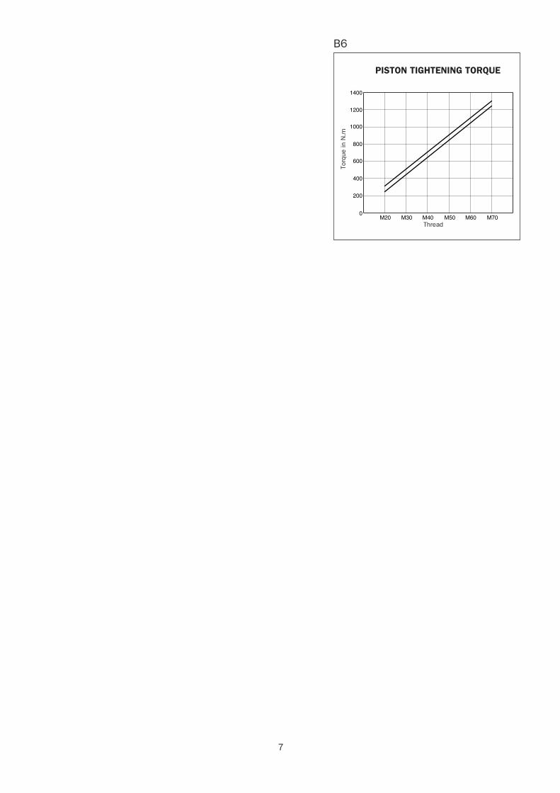
- Reassemble piston 4 (Fig. B1) on the stem.- Screw and lock nut 5 (Fig. B1) using a box wrenchand a torque wrench. See the table for thetightening torque (Fig. B6). Or, depending on theversion, screw piston 7 (Fig. B1) using a spannerwrench (see tightening torque Fig. B6) and block itwith locking screw 6 (Fig. B1).
NOTE : • The locking screw should be fitted usingLoctite 243, see section E.
• Tightening torque for the screw : 20 Nm.• Strike with a chisel to drive the screw into
the metal.
Tige 1
Bague de fermeture 2
Piston 4Ecrou 5 Vis 6
Piston 7
B1
Tige 1
Bague de fermeture 2
Piston 4
B2
Tige 1
Bague de fermeture 2
B3
Tige 1
Comparateur
B4
Tige 1
Bague de fermeture 2
B5
Locking ring 2
Stem 1 Piston 4 Piston 7
Screw 6Nut 5
Locking ring 2
Stem 1 Piston 4
Locking ring 2
Stem 1
Comparator
Stem 1
Locking ring 2
Stem 1
7
M20
COUPLE DE SERRAGE PISTON
1000
1200
1400
800
600
400
200
0M30 M40
Filetage
Cou
ple
en N
.m
M60M50 M70
B6
PISTON TIGHTENING TORQUE
Thread
Torq
ue in
N.m
8
C - REMOVAL AND REASSEMBLY OF THE PISTON SEALS AND RING
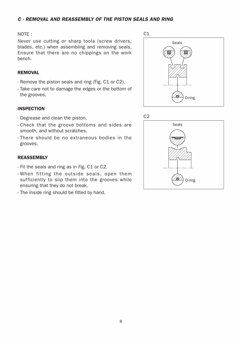
NOTE :Never use cutting or sharp tools (screw drivers,blades, etc.) when assembling and removing seals.Ensure that there are no chippings on the workbench.
REMOVAL
- Remove the piston seals and ring (Fig. C1 or C2).- Take care not to damage the edges or the bottom ofthe grooves.
INSPECTION
- Degrease and clean the piston.- Check that the groove bottoms and sides aresmooth, and without scratches.
- There should be no extraneous bodies in thegrooves.
REASSEMBLY
- Fit the seals and ring as in Fig. C1 or C2.- When fitt ing the outside seals, open themsuf ficiently to slip them into the grooves whileensuring that they do not break.
- The inside ring should be fitted by hand.
Joint torique
Joints d'étanchéité
C1
Joint torique
Joint d'étanchéité
C2
Seals
O-ring
Seals
O-ring
9
Embout 1
Joint
Poinçon 2
D3
D - REMOVAL AND REASSEMBLY OF THE SEALS AND RINGS ON THE LOCKING RING
NOTE :Never use cutting or sharp tools (screw drivers,blades, etc.) when assembling and removing seals.Ensure that there are no chippings on the workbench.
REMOVAL
- Remove the locking ring seals and rings.- Take care not to damage the edges or the bottom ofthe grooves.
INSPECTION
- Degrease and clean the locking ring.- Check that the groove bottoms and sides aresmooth, and without scratches.
- There should be no extraneous bodies in thegrooves.
- Thread the bare ring on the stem and slide it overits whole length.
- The gap should not be excessive, but it should notgrip either.
REASSEMBLY
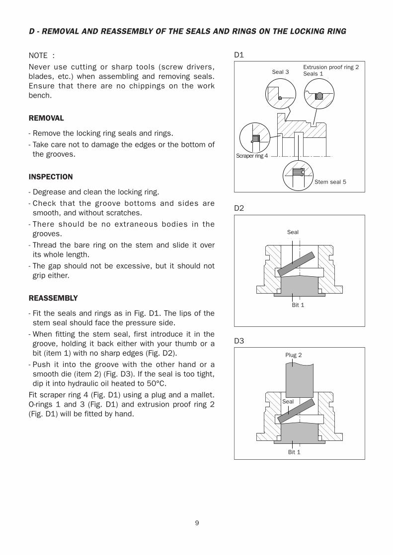
- Fit the seals and rings as in Fig. D1. The lips of thestem seal should face the pressure side.
- When fitting the stem seal, first introduce it in thegroove, holding it back either with your thumb or abit (item 1) with no sharp edges (Fig. D2).
- Push it into the groove with the other hand or asmooth die (item 2) (Fig. D3). If the seal is too tight,dip it into hydraulic oil heated to 50°C.
Fit scraper ring 4 (Fig. D1) using a plug and a mallet.O-rings 1 and 3 (Fig. D1) and extrusion proof ring 2(Fig. D1) will be fitted by hand.
Joint tige 5
Joint torique 3 Joint torique 1
Racleur 4
Joint anti-extrusion 2
D1
Joint
Embout 1
D2
Seal 3
Scraper ring 4
Extrusion proof ring 2Seals 1
Stem seal 5
Seal
Bit 1
Bit 1
Plug 2
Seal
10
E - APPLICATION OF THE THREAD LOCKING MATERIAL
CHARACTERISTICS
Light thread locking material (Loctite 222)
Application on the locking ring threads.
Without activation agentHandling time 10 - 30 minutesUse time 3 - 6 hours(Placing of the cylinder under pressure)With N Loctite activation agentHandling time 10 - 20 minutesUse time 2 - 4 hours(Placing of the cylinder under pressure)
Shearing strength 15.4 - 4 N/mm2
Medium thread locking material (Loctite 243)
Application on the M8 screws to lock the pistons.
Without activation agentHandling time 10 - 20 minutesUse time 3 - 6 hours(Placing of the cylinder under pressure)With N Loctite activation agentHandling time 5 - 15 minutesUse time 2 - 4 hours(Placing of the cylinder under pressure)
Shearing strength 5 - 7.5 N/mm2
REMOVAL
If the parts fitted with locking material cannot be removed using standard tools, we recommendheating the glued area to T = 250°C, preferably using a hot air pistol rather than a blowpipe.
REMARK
If the temperature is near 0°C, we recommend using a Loctite activation agent for the assembly,in addition, this will limit the polymerisation time.
11
F - SPECIAL OUTER TELESCOPE CYLINDER DISASSEMBLY MT 1740
PROCEDURE FOLLOW-UP
1 - CYLINDER ASSEMBLY AND DISASSEMBLY
2 - ROD + ELEMENT KIT ASSEMBLY AND DISASSEMBLY
3 - MOUNTING THE SEALS ON THE LOCKING RINGS
4 - MOUNTING THE SEALS ON THE PISTONS
12
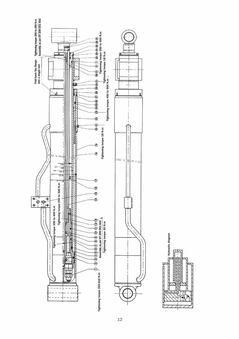
Tigh
teni
ng t
orqu
e 20
2-21
6 N
.m
Tigh
teni
ng t
orqu
e 35
0 to
400
N.m
Tigh
teni
ng t
orqu
e 25
0 to
300
N.m
Tigh
teni
ng t
orqu
e 20
N.m
Tigh
teni
ng t
orqu
e 18
N.m
Tigh
teni
ng t
orqu
e 45
0 to
500
N.mTigh
teni
ng t
orqu
e 18
N.m
Tigh
teni
ng t
orqu
e 35
0 to
400
N.m
Fold
bac
k th
e fla
nge
into
a s
ingl
e sl
otTi
ghte
ning
torq
ue 2
00 to
250
N.m
Asse
mbl
y as
per
DT
209
001
602
Hyd
raul
ic d
iagr
am
Asse
mbl
y as
per
DT
209
001
602
13
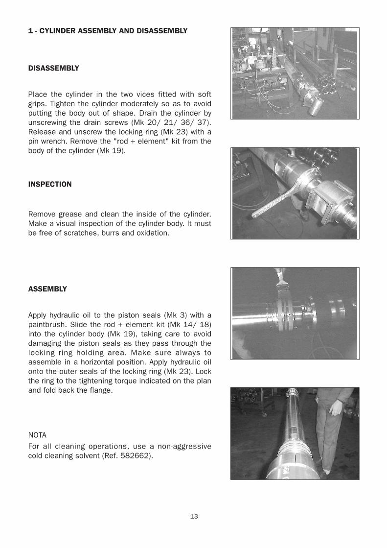
1 - CYLINDER ASSEMBLY AND DISASSEMBLY
DISASSEMBLY
Place the cylinder in the two vices fitted with softgrips. Tighten the cylinder moderately so as to avoidputting the body out of shape. Drain the cylinder byunscrewing the drain screws (Mk 20/ 21/ 36/ 37).Release and unscrew the locking ring (Mk 23) with apin wrench. Remove the "rod + element" kit from thebody of the cylinder (Mk 19).
INSPECTION
Remove grease and clean the inside of the cylinder.Make a visual inspection of the cylinder body. It mustbe free of scratches, burrs and oxidation.
ASSEMBLY
Apply hydraulic oil to the piston seals (Mk 3) with apaintbrush. Slide the rod + element kit (Mk 14/ 18)into the cylinder body (Mk 19), taking care to avoiddamaging the piston seals as they pass through thelocking ring holding area. Make sure always toassemble in a horizontal position. Apply hydraulic oilonto the outer seals of the locking ring (Mk 23). Lockthe ring to the tightening torque indicated on the planand fold back the flange.
NOTAFor all cleaning operations, use a non-aggressivecold cleaning solvent (Ref. 582662).
14
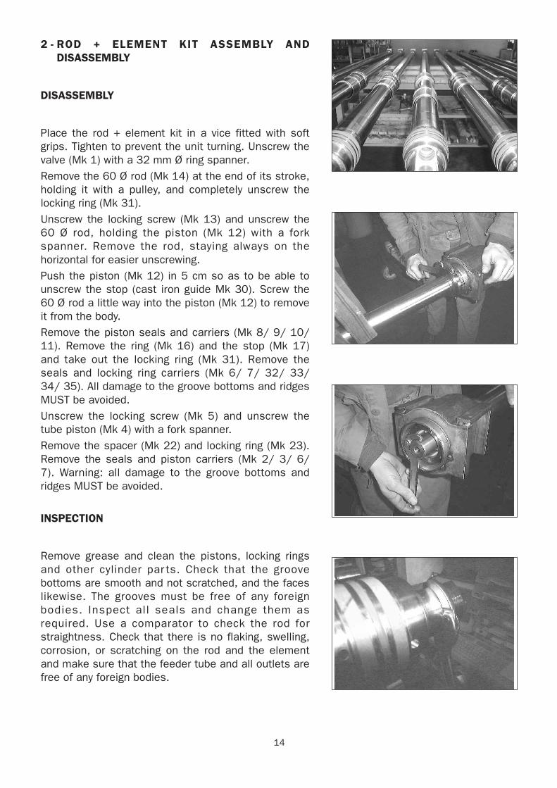
2 - ROD + ELEMENT KIT ASSEMBLY ANDDISASSEMBLY
DISASSEMBLY
Place the rod + element kit in a vice fitted with softgrips. Tighten to prevent the unit turning. Unscrew thevalve (Mk 1) with a 32 mm Ø ring spanner.Remove the 60 Ø rod (Mk 14) at the end of its stroke,holding it with a pulley, and completely unscrew thelocking ring (Mk 31).Unscrew the locking screw (Mk 13) and unscrew the60 Ø rod, holding the piston (Mk 12) with a forkspanner. Remove the rod, staying always on thehorizontal for easier unscrewing. Push the piston (Mk 12) in 5 cm so as to be able tounscrew the stop (cast iron guide Mk 30). Screw the60 Ø rod a little way into the piston (Mk 12) to removeit from the body. Remove the piston seals and carriers (Mk 8/ 9/ 10/11). Remove the ring (Mk 16) and the stop (Mk 17)and take out the locking ring (Mk 31). Remove theseals and locking ring carriers (Mk 6/ 7/ 32/ 33/34/ 35). All damage to the groove bottoms and ridgesMUST be avoided.Unscrew the locking screw (Mk 5) and unscrew thetube piston (Mk 4) with a fork spanner.Remove the spacer (Mk 22) and locking ring (Mk 23).Remove the seals and piston carriers (Mk 2/ 3/ 6/7). Warning: all damage to the groove bottoms andridges MUST be avoided.
INSPECTION
Remove grease and clean the pistons, locking ringsand other cylinder par ts. Check that the groovebottoms are smooth and not scratched, and the faceslikewise. The grooves must be free of any foreignbodies. Inspect all seals and change them asrequired. Use a comparator to check the rod forstraightness. Check that there is no flaking, swelling,corrosion, or scratching on the rod and the elementand make sure that the feeder tube and all outlets arefree of any foreign bodies.
15
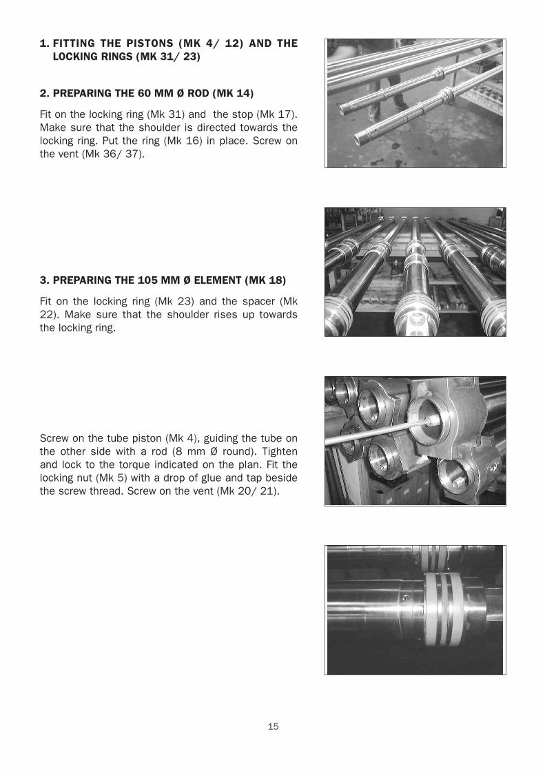
1. FITTING THE PISTONS (MK 4/ 12) AND THELOCKING RINGS (MK 31/ 23)
2. PREPARING THE 60 MM Ø ROD (MK 14)
Fit on the locking ring (Mk 31) and the stop (Mk 17).Make sure that the shoulder is directed towards thelocking ring. Put the ring (Mk 16) in place. Screw onthe vent (Mk 36/ 37).
3. PREPARING THE 105 MM Ø ELEMENT (MK 18)
Fit on the locking ring (Mk 23) and the spacer (Mk22). Make sure that the shoulder rises up towardsthe locking ring.
Screw on the tube piston (Mk 4), guiding the tube onthe other side with a rod (8 mm Ø round). Tightenand lock to the torque indicated on the plan. Fit thelocking nut (Mk 5) with a drop of glue and tap besidethe screw thread. Screw on the vent (Mk 20/ 21).
16
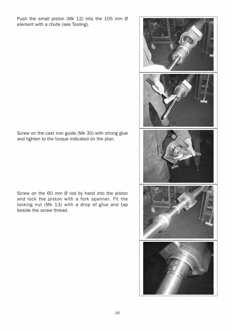
Push the small piston (Mk 12) into the 105 mm Øelement with a chute (see Tooling).
Screw on the cast iron guide (Mk 30) with strong glueand tighten to the torque indicated on the plan.
Screw on the 60 mm Ø rod by hand into the pistonand lock the piston with a fork spanner. Fit thelocking nut (Mk 13) with a drop of glue and tapbeside the screw thread.
17
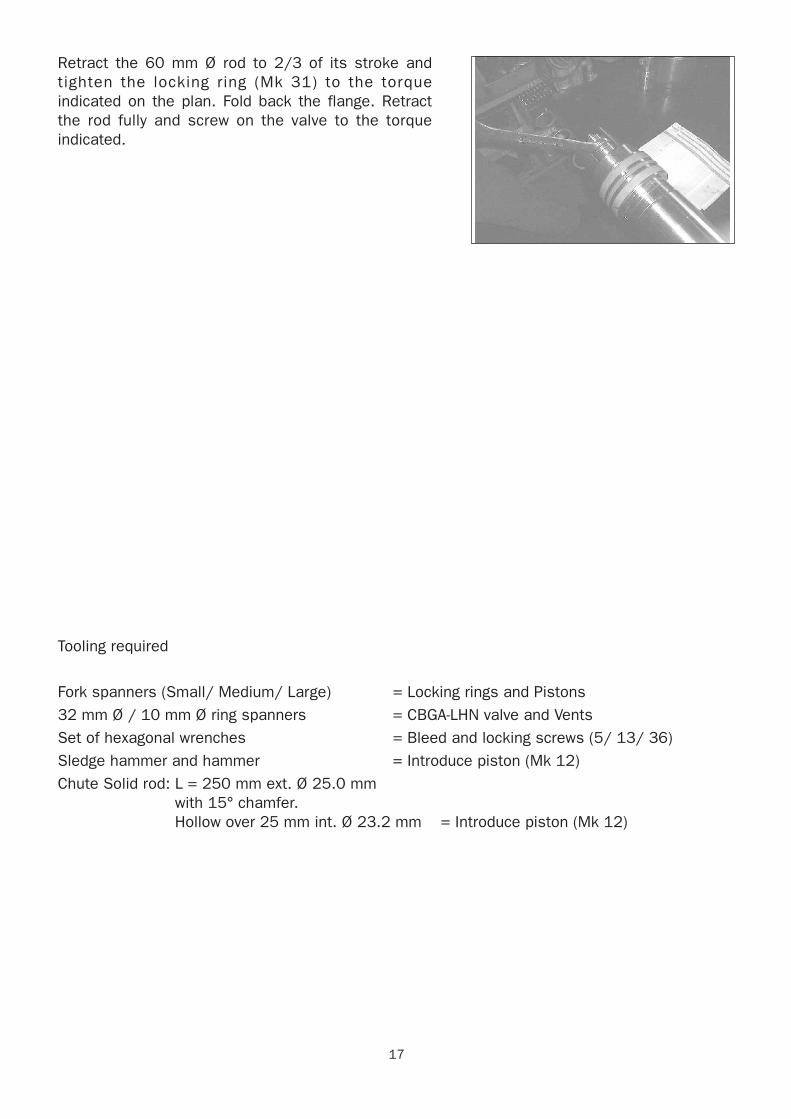
Retract the 60 mm Ø rod to 2/3 of its stroke andtighten the locking ring (Mk 31) to the torqueindicated on the plan. Fold back the flange. Retractthe rod fully and screw on the valve to the torqueindicated.
Tooling required
Fork spanners (Small/ Medium/ Large) = Locking rings and Pistons32 mm Ø / 10 mm Ø ring spanners = CBGA-LHN valve and VentsSet of hexagonal wrenches = Bleed and locking screws (5/ 13/ 36)Sledge hammer and hammer = Introduce piston (Mk 12)Chute Solid rod: L = 250 mm ext. Ø 25.0 mm
with 15° chamfer.Hollow over 25 mm int. Ø 23.2 mm = Introduce piston (Mk 12)
18
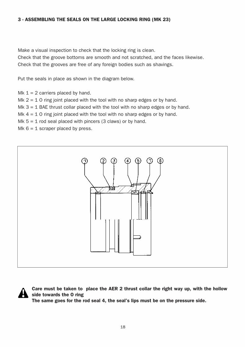
3 - ASSEMBLING THE SEALS ON THE LARGE LOCKING RING (MK 23)
Make a visual inspection to check that the locking ring is clean.Check that the groove bottoms are smooth and not scratched, and the faces likewise. Check that the grooves are free of any foreign bodies such as shavings.
Put the seals in place as shown in the diagram below.
Mk 1 = 2 carriers placed by hand.Mk 2 = 1 O ring joint placed with the tool with no sharp edges or by hand.Mk 3 = 1 BAE thrust collar placed with the tool with no sharp edges or by hand.Mk 4 = 1 O ring joint placed with the tool with no sharp edges or by hand.Mk 5 = 1 rod seal placed with pincers (3 claws) or by hand.Mk 6 = 1 scraper placed by press.
Care must be taken to place the AER 2 thrust collar the right way up, with the hollowside towards the O ringThe same goes for the rod seal 4, the seal's lips must be on the pressure side.
19
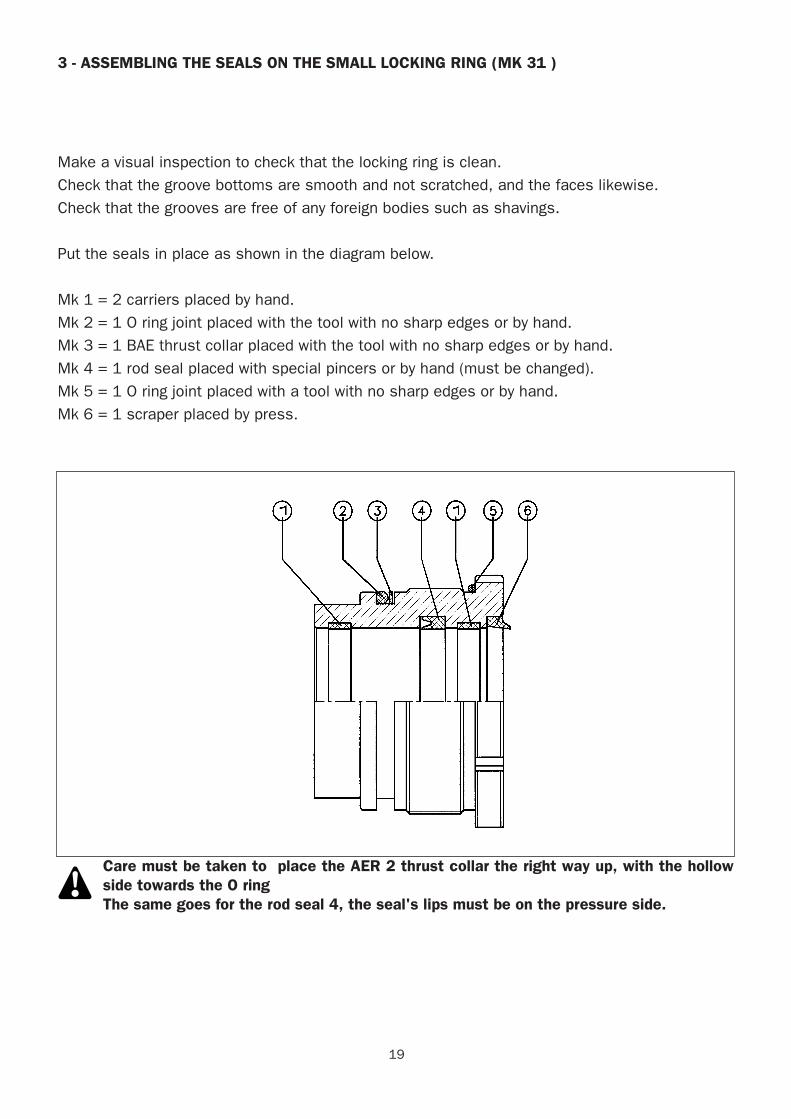
3 - ASSEMBLING THE SEALS ON THE SMALL LOCKING RING (MK 31 )
Make a visual inspection to check that the locking ring is clean.Check that the groove bottoms are smooth and not scratched, and the faces likewise. Check that the grooves are free of any foreign bodies such as shavings.
Put the seals in place as shown in the diagram below.
Mk 1 = 2 carriers placed by hand.Mk 2 = 1 O ring joint placed with the tool with no sharp edges or by hand.Mk 3 = 1 BAE thrust collar placed with the tool with no sharp edges or by hand.Mk 4 = 1 rod seal placed with special pincers or by hand (must be changed).Mk 5 = 1 O ring joint placed with a tool with no sharp edges or by hand.Mk 6 = 1 scraper placed by press.
Care must be taken to place the AER 2 thrust collar the right way up, with the hollowside towards the O ringThe same goes for the rod seal 4, the seal's lips must be on the pressure side.
20
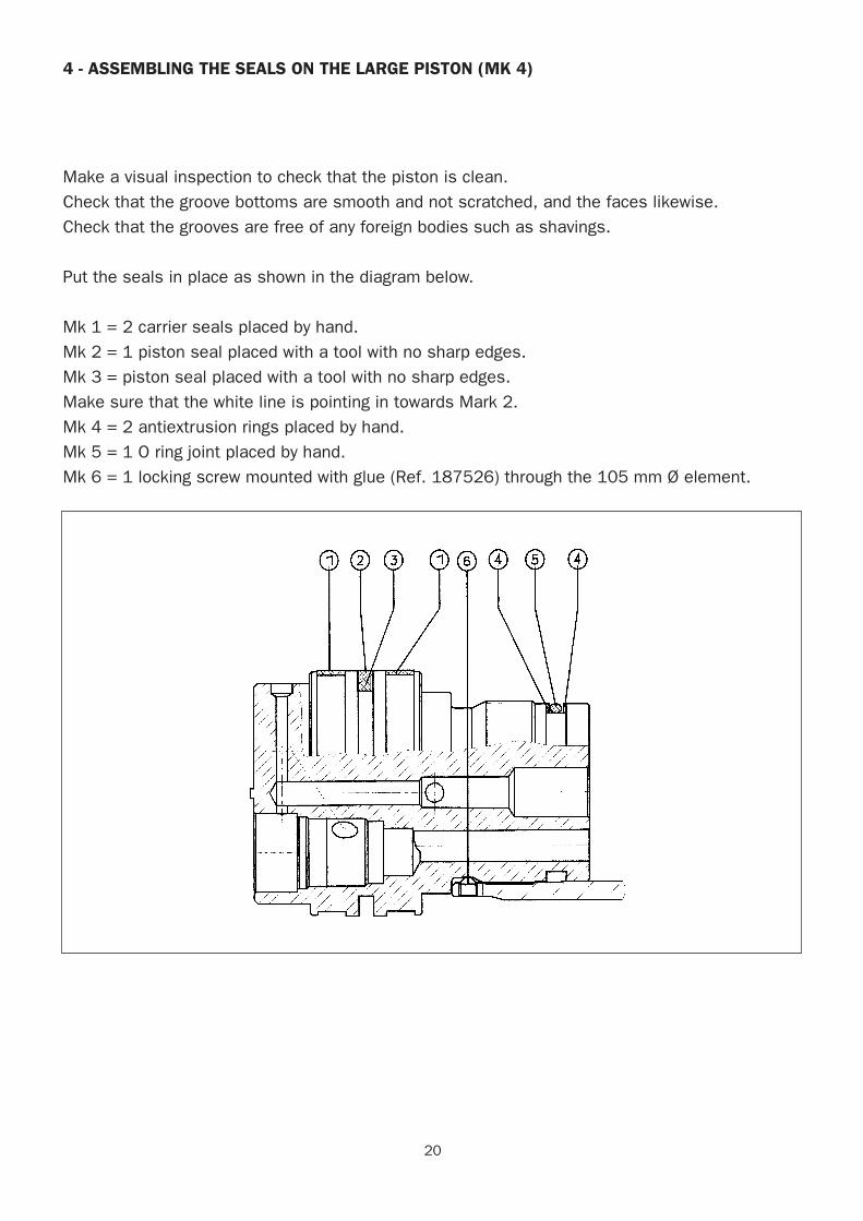
4 - ASSEMBLING THE SEALS ON THE LARGE PISTON (MK 4)
Make a visual inspection to check that the piston is clean.Check that the groove bottoms are smooth and not scratched, and the faces likewise. Check that the grooves are free of any foreign bodies such as shavings.
Put the seals in place as shown in the diagram below.
Mk 1 = 2 carrier seals placed by hand.Mk 2 = 1 piston seal placed with a tool with no sharp edges.Mk 3 = piston seal placed with a tool with no sharp edges.Make sure that the white line is pointing in towards Mark 2.Mk 4 = 2 antiextrusion rings placed by hand.Mk 5 = 1 O ring joint placed by hand.Mk 6 = 1 locking screw mounted with glue (Ref. 187526) through the 105 mm Ø element.
21
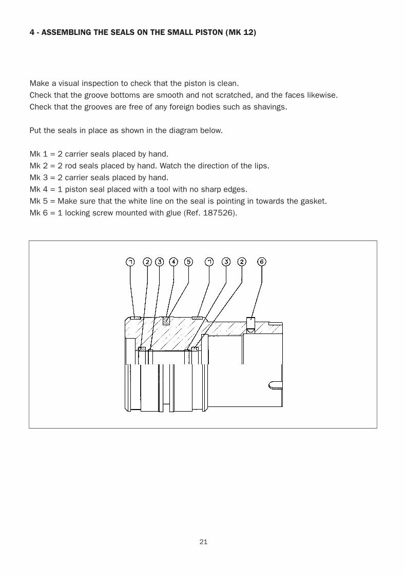
4 - ASSEMBLING THE SEALS ON THE SMALL PISTON (MK 12)
Make a visual inspection to check that the piston is clean.Check that the groove bottoms are smooth and not scratched, and the faces likewise. Check that the grooves are free of any foreign bodies such as shavings.
Put the seals in place as shown in the diagram below.
Mk 1 = 2 carrier seals placed by hand.Mk 2 = 2 rod seals placed by hand. Watch the direction of the lips.Mk 3 = 2 carrier seals placed by hand.Mk 4 = 1 piston seal placed with a tool with no sharp edges.Mk 5 = Make sure that the white line on the seal is pointing in towards the gasket.Mk 6 = 1 locking screw mounted with glue (Ref. 187526).
22
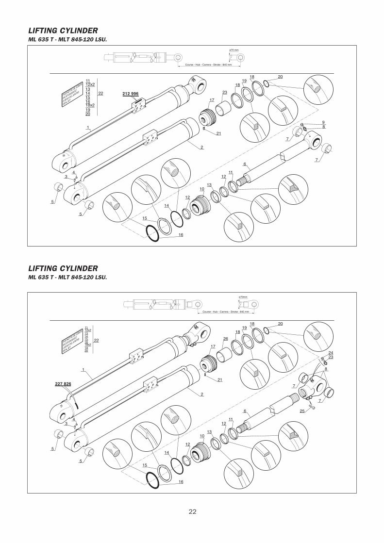
LIFTING CYLINDERML 635 T - MLT 845-120 LSU.
POCHETTE DE JOINTS
DICHTUNGSATZ
JUEGO DE JUNTAS
SEAL KIT
212 996
ø70 mm
Course - Hub - Carrera - Stroke : 845 mm
1112x2
18x2
1314
16
1920
1522
7
7
6
1112
1310
12
14
15
5
3 4
1
5
16
89
201819
18
23
21
2
17
LIFTING CYLINDERML 635 T - MLT 845-120 LSU.
POCHETTE DE JOINTS
DICHTUNGSATZ
JUEGO DE JUNTAS
SEAL KIT
227 826
ø70mm
Course - Hub - Carrera - Stroke : 845 mm
1112x2
18x2
1314
16
1920
15 22
7
7
256
1112
1310
12
14
15
5
3 4
1
5
16
8
2423
201819
18
21
2
17
26
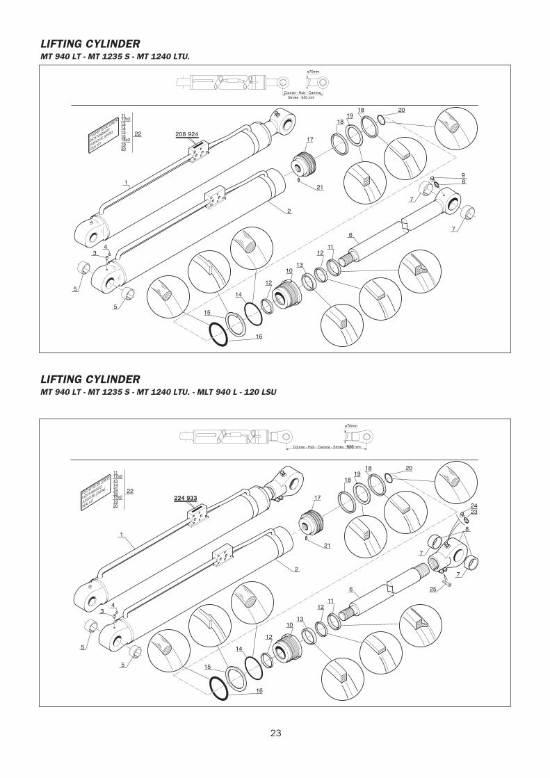
LIFTING CYLINDERMT 940 LT - MT 1235 S - MT 1240 LTU.
POCHETTE DE JOINTS
DICHTUNGSATZ
JUEGO DE JUNTAS
SEAL KIT
208 924
ø70mm
Course - Hub - CarreraStroke : 920 mm
1112x2
18x2
1314
16
1920
15 22
7
7
6
1112
1310
12
14
15
5
3 4
1
5
16
89
201819
18
21
2
17
23
LIFTING CYLINDERMT 940 LT - MT 1235 S - MT 1240 LTU. - MLT 940 L - 120 LSU
POCHETTE DE JOINTS
DICHTUNGSATZ
JUEGO DE JUNTAS
SEAL KIT224 933
ø70mm
Course - Hub - Carrera - Stroke : 920 mm
1112x2
18x2
1314
16
1920
15 22
7
7
256
1112
1310
12
14
15
5
3 4
1
5
16
8
2423
201819
18
21
2
17
24
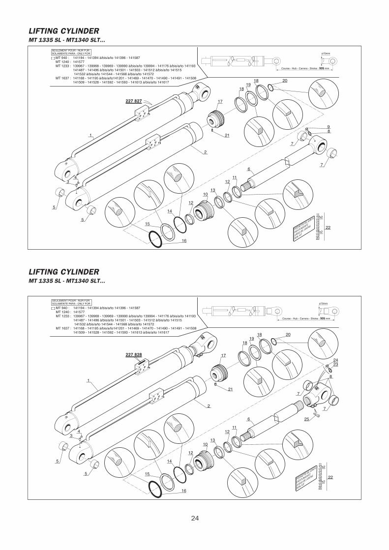
LIFTING CYLINDERMT 1335 SL - MT1340 SLT...
POCHETTE DE JOINTS
DICHTUNGSATZ
JUEGO DE JUNTAS
SEAL KIT
227 827
ø70mm
Course - Hub - Carrera - Stroke : 905 mm
1112x2
18x2
1314
16
1920
15 22
7
7
6
1112
1310
12
14
15
5
3 4
1
5
16
89
201819
18
21
2
17
MT 940 : 141194 - 141394 à/bis/a/to 141396 - 141587MT 1240 : 141577MT 1233 : 139967 - 139968 - 139969 - 139990 à/bis/a/to 139994 - 141176 à/bis/a/to 141193 141487 - 141496 à/bis/a/to 141501 - 141503 - 141512 à/bis/a/to 141515 141532 à/bis/a/to 141544 - 141568 à/bis/a/to 141572MT 1637 : 141168 - 141195 à/bis/a/to141201 - 141469 - 141470 - 141490 - 141491 - 141508 141509 - 141528 - 141592 - 141593 - 141613 à/bis/a/to 141617
SEULEMENT POUR - NUR FURSOLAMENTE PARA - ONLY FOR
LIFTING CYLINDERMT 1335 SL - MT1340 SLT...
POCHETTE DE JOINTS
DICHTUNGSATZ
JUEGO DE JUNTAS
SEAL KIT
227 828
ø70mm
Course - Hub - Carrera - Stroke : 905 mm
1112x2
18x2
1314
16
1920
15 22
7
7
256
1112
1310
12
14
15
5
3 4
1
5
16
8
2423
201819
18
21
2
17
MT 940 : 141194 - 141394 à/bis/a/to 141396 - 141587MT 1240 : 141577MT 1233 : 139967 - 139968 - 139969 - 139990 à/bis/a/to 139994 - 141176 à/bis/a/to 141193 141487 - 141496 à/bis/a/to 141501 - 141503 - 141512 à/bis/a/to 141515 141532 à/bis/a/to 141544 - 141568 à/bis/a/to 141572MT 1637 : 141168 - 141195 à/bis/a/to141201 - 141469 - 141470 - 141490 - 141491 - 141508 141509 - 141528 - 141592 - 141593 - 141613 à/bis/a/to 141617
SEULEMENT POUR - NUR FURSOLAMENTE PARA - ONLY FOR
25
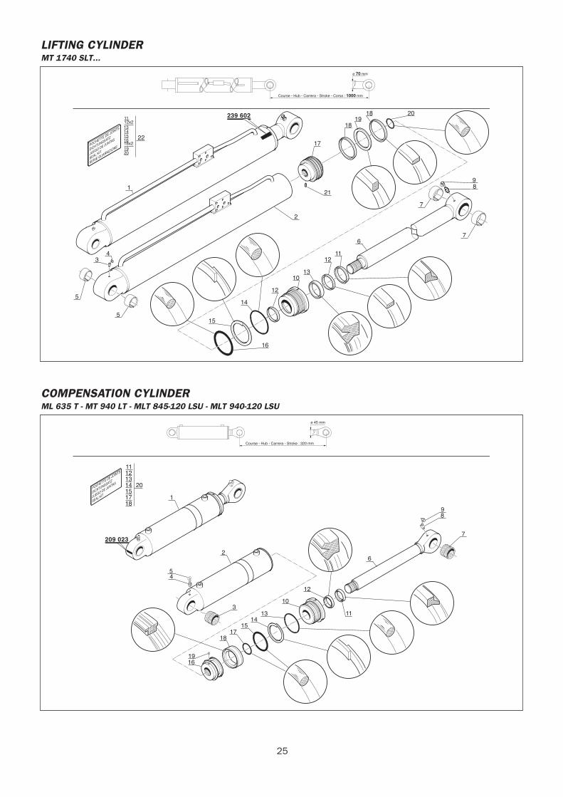
LIFTING CYLINDERMT 1740 SLT...
ø 70 mm
Course - Hub - Carrera - Stroke - Corsa : 1000 mm
POCHETTE DE JOINTS
DICHTUNGSATZ
JUEGO DE JUNTAS
SEAL KIT
SERIE GUARNIZIONE
239 6021112x2
18x2
1314
16
1920
15 22
7
7
6
1112
1310
12
14
15
5
3 4
1
5
16
89
201819
18
21
2
17
COMPENSATION CYLINDERML 635 T - MT 940 LT - MLT 845-120 LSU - MLT 940-120 LSU
POCHETTE DE JOINTS
DICHTUNGSATZ
JUEGO DE JUNTAS
SEAL KIT
ø 45 mm
Course - Hub - Carrera - Stroke : 320 mm
209 023
11121314
1718
1520
1
2
1916
1817
1514
13
10
12
6
54
311
98
7
26
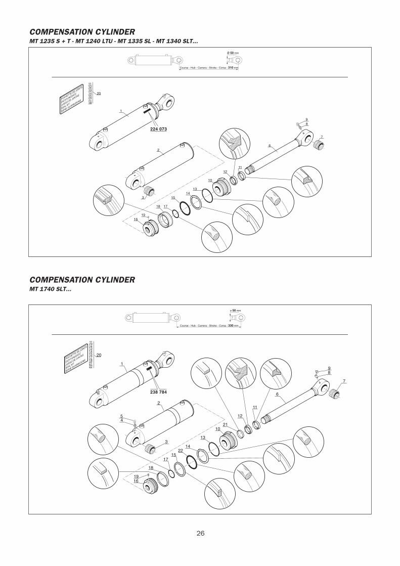
COMPENSATION CYLINDERMT 1235 S + T - MT 1240 LTU - MT 1335 SL - MT 1340 SLT...
ø 50 mm
224 073
Course - Hub - Carrera - Stroke - Corsa : 310 mm
POCHETTE DE JOINTS
DICHTUNGSATZ
JUEGO DE JUNTAS
SEAL KIT
SERIE GUARNIZIONE
1
2
3
1619
18 17
1514
13
10
1211
6
98
7
11121314151718
20
COMPENSATION CYLINDERMT 1740 SLT...
ø 50 mm
POCHETTE DE JOINTS
DICHTUNGSATZ
JUEGO DE JUNTAS
SEAL KIT
SERIE GUARNIZIONE
Course - Hub - Carrera - Stroke - Corsa : 330 mm
238 784
11121314
1718
15
2122
20
1
2
1916
18
1715
2214
13
10
12
6
54
3
21
11
98
7
27
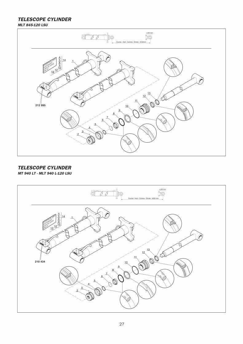
TELESCOPE CYLINDERMLT 845-120 LSU
ø 60 mm
Course - Hub - Carrera - Stroke : 3150mm
POCHETTE DE JOINTS
DICHTUNGSATZ
JUEGO DE JUNTAS
SEAL KIT
212 995
4 5
910
1213
814 1
23
45
67
89
10
11
1213
TELESCOPE CYLINDERMT 940 LT - MLT 940 L-120 LSU
ø 60 mm
Course - Hub - Carrera - Stroke : 3520 mm
210 434
POCHETTE DE JOINTS
DICHTUNGSATZ
JUEGO DE JUNTAS
SEAL KIT
4 5
910
1213
814 1
23
45
67
89
10
11
1213
28
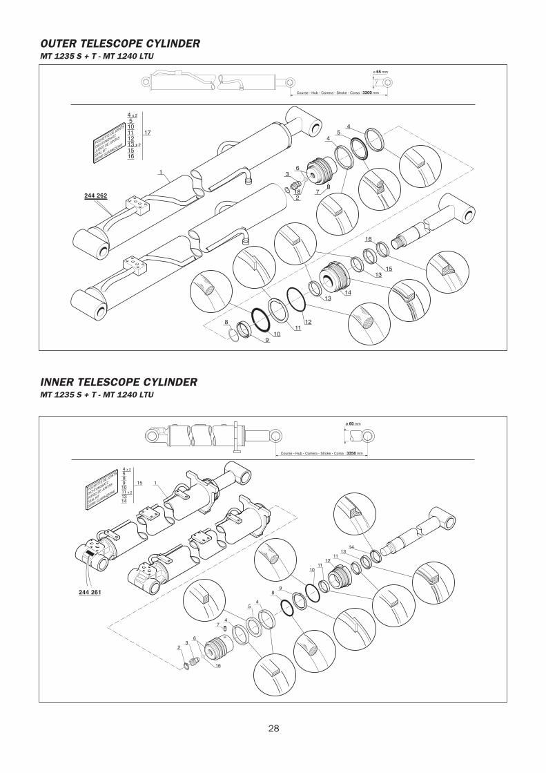
OUTER TELESCOPE CYLINDERMT 1235 S + T - MT 1240 LTU
ø 65 mm
244 262
Course - Hub - Carrera - Stroke - Corsa : 3300 mm
POCHETTE DE JOINTS
DICHTUNGSATZ
JUEGO DE JUNTAS
SEAL KIT
SERIE GUARNIZIONE
3
18
8
16
6
45
4
2
910
1112
1314
1315
7
1
16
5
1112
4 x 2
13 x 2
15
1017
INNER TELESCOPE CYLINDERMT 1235 S + T - MT 1240 LTU
ø 60 mm
Course - Hub - Carrera - Stroke - Corsa : 3358 mm
POCHETTE DE JOINTS
DICHTUNGSATZ
JUEGO DE JUNTAS
SEAL KIT
SERIE GUARNIZIONE
244 261
11 x 2
23
16
6
74
54
89
1011
1211
1314
1413
110985
15
4 x 2
29
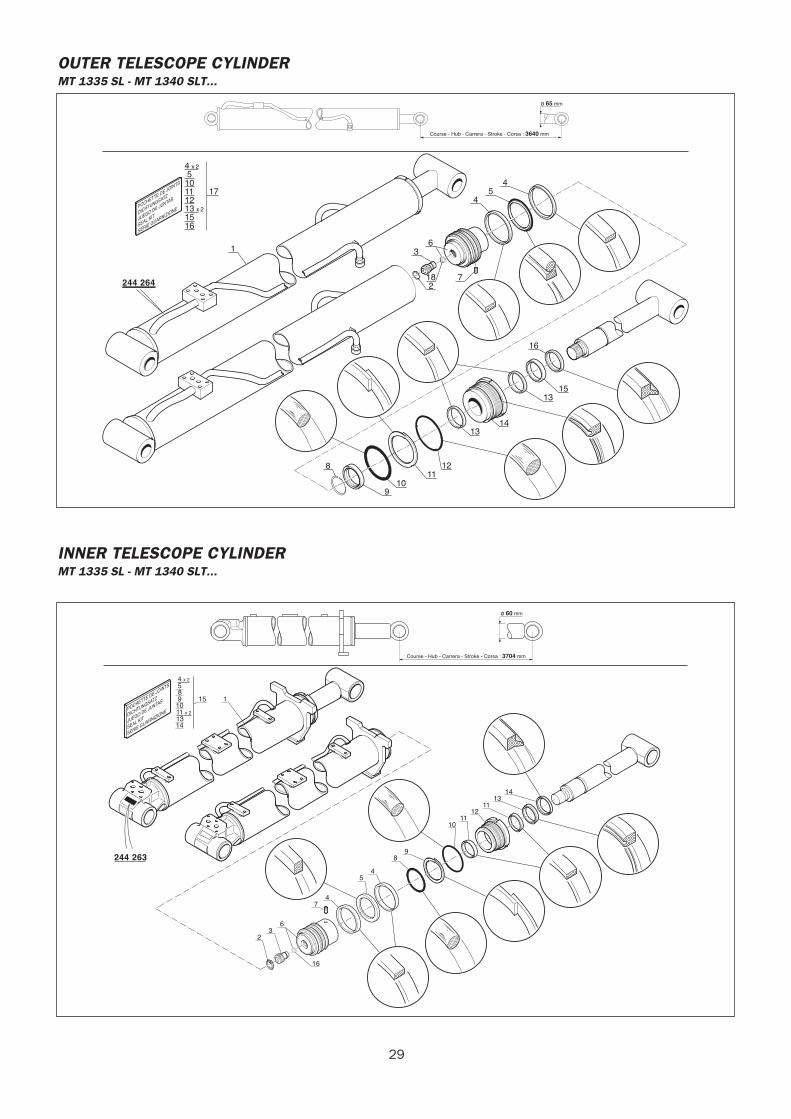
OUTER TELESCOPE CYLINDERMT 1335 SL - MT 1340 SLT...
ø 65 mm
244 264
Course - Hub - Carrera - Stroke - Corsa : 3640 mm
POCHETTE DE JOINTS
DICHTUNGSATZ
JUEGO DE JUNTAS
SEAL KIT
SERIE GUARNIZIONE
3
18
8
16
6
45
4
2
910
1112
1314
1315
7
1
16
5
1112
4 x 2
13 x 2
15
1017
INNER TELESCOPE CYLINDERMT 1335 SL - MT 1340 SLT...
ø 60 mm
Course - Hub - Carrera - Stroke - Corsa : 3704 mm
POCHETTE DE JOINTS
DICHTUNGSATZ
JUEGO DE JUNTAS
SEAL KIT
SERIE GUARNIZIONE
244 263
11 x 2
23
16
6
74
54
89
1011
1211
1314
1413
110985
15
4 x 2
30
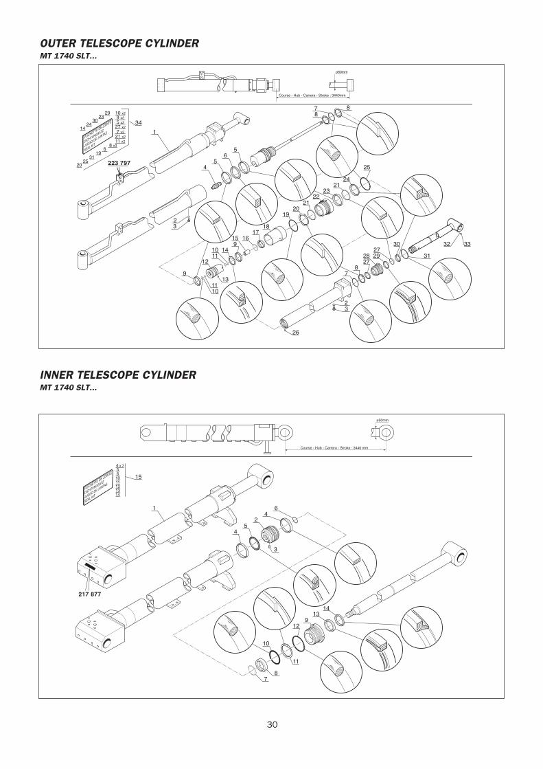
OUTER TELESCOPE CYLINDERMT 1740 SLT...
ø60mm
Course - Hub - Carrera - Stroke : 3440mm
POCHETTE DE JOINTS
DICHTUNGSATZ
JUEGO DE JUNTAS
SEAL KIT
223 797
78
8
5
13
2
65
25
2421
1
2322
2120
19
17
4
18
16
1112
9
2729
30
31
78
2728
3
26
3332
23
10 149
15
11
10 x2 9 x2 5 x227 x2 7 x221 x211 x2
619
3125
20
8 x3
2923
3024
1434
10
INNER TELESCOPE CYLINDERMT 1740 SLT...
ø50mm
Course - Hub - Carrera - Stroke : 3440 mm
POCHETTE DE JOINTS
DICHTUNGSATZ
JUEGO DE JUNTAS
SEAL KIT
217 877
64
2
1
54
14
11
139
12
10
78
3
15
4 x 25
1011121314
6
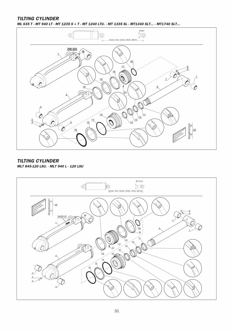
31
TILTING CYLINDERML 635 T - MT 940 LT - MT 1235 S + T - MT 1240 LTU. - MT 1335 SL - MT1340 SLT... - MT1740 SLT...
POCHETTE DE JOINTS
DICHTUNGSATZ
JUEGO DE JUNTAS
SEAL KIT
ø75mm
Course - Hub - Carrera - Stroke : 385mm
208 923
1112x2
18x2
1314
16
1920
15 22
1
2
18
19
18
17
20
6
10
1415
16
12
21
98
77
5
534
1312
11
TILTING CYLINDERMLT 845-120 LSU. - MLT 940 L - 120 LSU
ø 75 mm
Course - Hub - Carrera - Stroke - Corsa : 385 mm
245515
POCHETTE DE JOINTS
DICHTUNGSATZ
JUEGO DE JUNTAS
SEAL KIT
SERIE GUARNIZIONE
11
1314151618 x 2
12 x 2
1920
22
1
2
5
3
4
16
15
14
5
12
13
1018
21
17
19
18
20
7
7
98
12
11
6
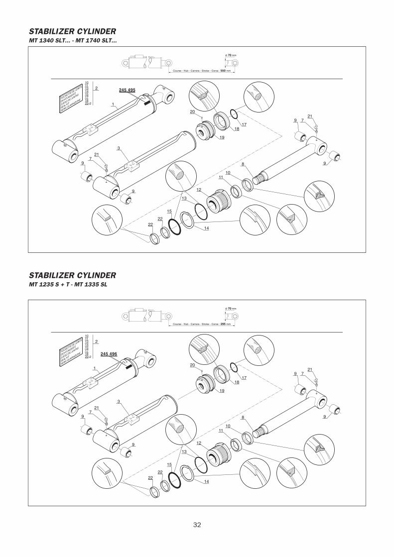
32
STABILIZER CYLINDERMT 1340 SLT... - MT 1740 SLT...
ø 70 mm
245 495
Course - Hub - Carrera - Stroke - Corsa : 550 mm
POCHETTE DE JOINTS
DICHTUNGSATZ
JUEGO DE JUNTAS
SEAL KIT
SERIE GUARNIZIONE
10111314
171822X2
15
2
1
3
721
9
9
14
13
12
1110
8 9
9 721
1718
19
20
15
2222
STABILIZER CYLINDERMT 1235 S + T - MT 1335 SL
ø 70 mm
245 496
Course - Hub - Carrera - Stroke - Corsa : 295 mm
POCHETTE DE JOINTS
DICHTUNGSATZ
JUEGO DE JUNTAS
SEAL KIT
SERIE GUARNIZIONE
10111314
171822X2
15
2
1
3
721
9
9
14
13
12
1110
8 9
9 721
1718
19
20
15
2222
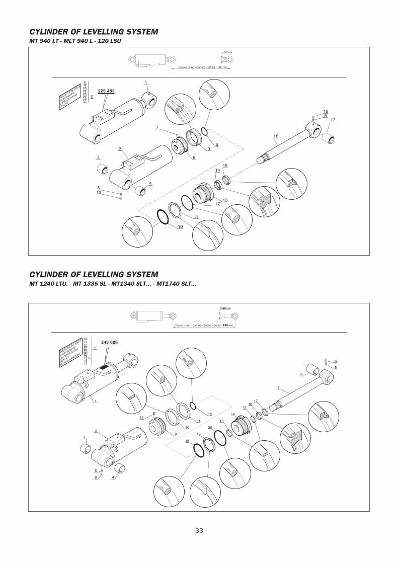
33
CYLINDER OF LEVELLING SYSTEMMT 940 LT - MLT 940 L - 120 LSU
POCHETTE DE JOINTS
DICHTUNGSATZ
JUEGO DE JUNTAS
SEAL KIT
ø 50 mm
Course - Hub - Carrera - Stroke : 198 mm
225 483
8 91011
1415
12 2
3
4
518
4
6
98
10
11
1213
14
185
17
15
16
7
1
CYLINDER OF LEVELLING SYSTEMMT 1240 LTU. - MT 1335 SL - MT1340 SLT... - MT1740 SLT...
ø 50 mm
Course - Hub - Carrera - Stroke - Corsa : 139 mm
243 606
POCHETTE DE JOINTS
DICHTUNGSATZ
JUEGO DE JUNTAS
SEAL KIT
SERIE GUARNIZIONE
1011
1617
12181920
2
15 x 2
1
4
11
12
18
19
20
15
14
1516
17
7
8
5
6
6
5
4
3
13
9
10

34
ML 635 Turbo Série 3-E2
15 / 11 / 2007
HYDRAULIC DIAGRAM
70-6-245206 EN

2 15/11/200770-6-245206EN
3 70-6-245206EN15/11/2007
-HYDRAULIC DIAGRAM
ML 635 Turbo Série 3-E2 . . . . . . . . . . . . . . . . . . . . . . . . . . . . . . . . . . . . . . . . . . . . . . . 4
CONTENTS
4 15/11/200770-6-245206EN
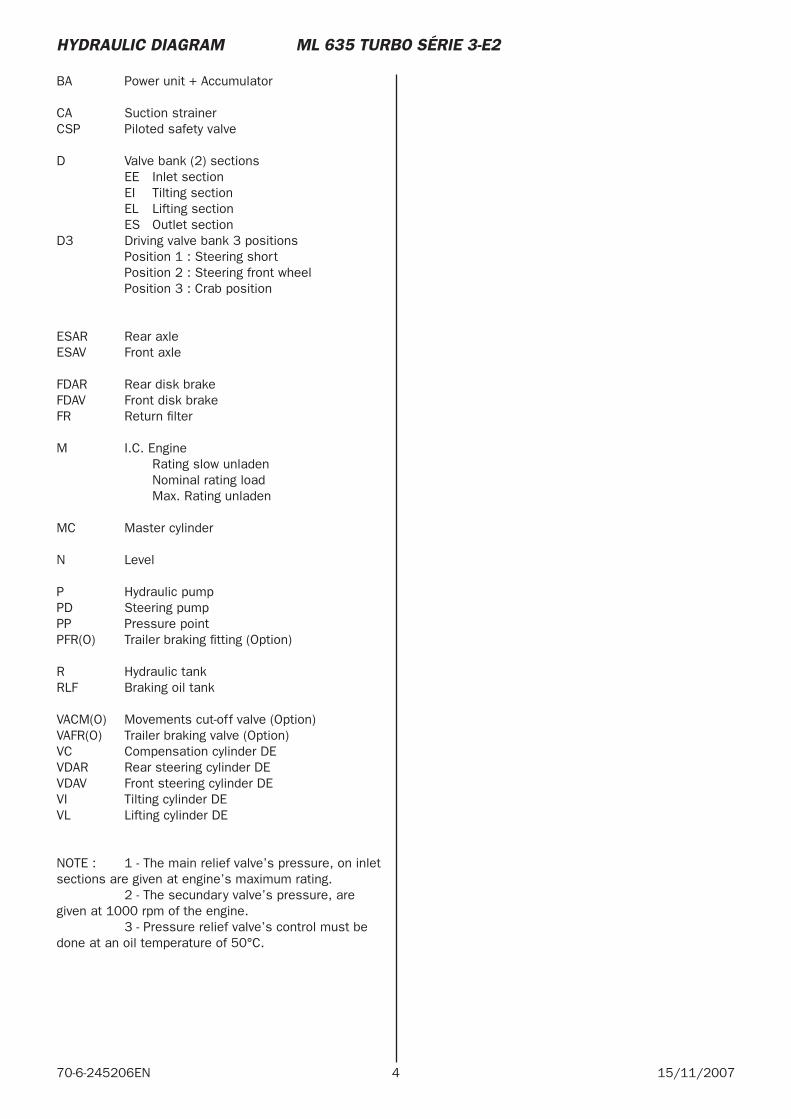
BA Power unit + Accumulator
CA Suction strainerCSP Piloted safety valve
D Valve bank (2) sections EE Inlet section EI Tilting section EL Lifting section ES Outlet sectionD3 Driving valve bank 3 positions Position 1 : Steering short Position 2 : Steering front wheel Position 3 : Crab position
ESAR Rear axleESAV Front axle
FDAR Rear disk brakeFDAV Front disk brakeFR Return fi lter
M I.C. Engine Rating slow unladen Nominal rating load Max. Rating unladen
MC Master cylinder
N Level
P Hydraulic pumpPD Steering pump PP Pressure point PFR(O) Trailer braking fi tting (Option)
R Hydraulic tankRLF Braking oil tank
VACM(O) Movements cut-off valve (Option)VAFR(O) Trailer braking valve (Option)VC Compensation cylinder DEVDAR Rear steering cylinder DEVDAV Front steering cylinder DEVI Tilting cylinder DEVL Lifting cylinder DE
NOTE : 1 - The main relief valve’s pressure, on inlet sections are given at engine’s maximum rating. 2 - The secundary valve’s pressure, are given at 1000 rpm of the engine. 3 - Pressure relief valve’s control must be done at an oil temperature of 50°C.
HYDRAULIC DIAGRAM ML 635 TURBO SÉRIE 3-E2
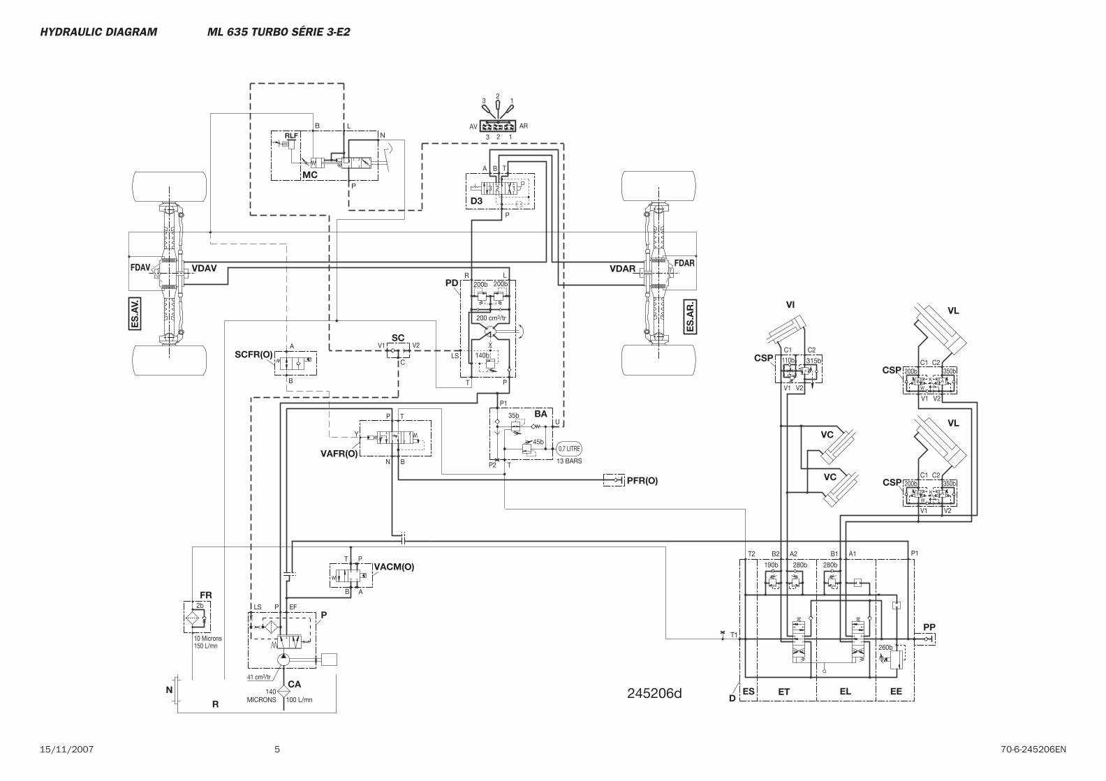
515/11/2007 70-6-245206EN
245206d
ES
.AV.
ES
.AR
.
MC
CSP
N
VL
VC CSP
VLVI
VC
CAET EE
PP
ESD
EL
P
R
FR
BA
D3
PD
SC
VDAVFDAV VDARFDAR
CSPSCFR(O)
VAFR(O)
PFR(O)
VACM(O)
T1
V2
C2350b
K
V1
W
C1200b
260b
P1A1B1T2
190b
B2 A2
280b 280b
150 L/mn
41 cm3/tr
10 Microns
2b EFLS P
140MICRONS 100 L/mn
0,7 LITRE
13 BARS
U
P1
35b
45b
TP2
200 cm3/tr
140b
200b
BA T
123
P
LR
PT
LS
V2V1
200b
ARAV
123
12
3
V2
C2350b
K
V1
W
C1200b
C
V2V1
C1 C2
B
TP
N
B
A
T
B A
P
AB
AB
P
NLB
RLF
110b 315b
Y
HYDRAULIC DIAGRAM ML 635 TURBO SÉRIE 3-E2

6 15/11/200770-6-245206EN

MLT 845 120 LSU Série 3-E2
15 / 11 / 2007
HYDRAULIC DIAGRAM
70-6-245025 EN

2 15/11/200770-6-245025EN
3 70-6-245025EN15/11/2007
-HYDRAULIQUE DIAGRAM
MLT 845 120 LSU Série 3-E2 Légende . . . . . . . . . . . . . . . . . 4
MLT 845 120 LSU Série 3-E2 N°: 203419. . . . . . . . . . . 5
MLT 845 120 LSU Série 3-E2 N°: 203420 . . . . . . . . . . . 9
CONTENTS
4 15/11/200770-6-245025EN
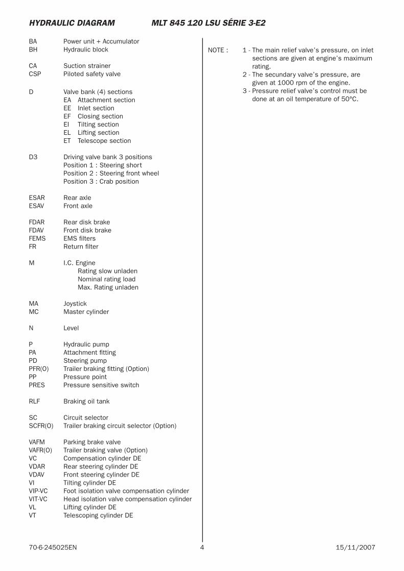
B A Power unit + AccumulatorBH Hydraulic block
CA Suction strainerCSP Piloted safety valve
D Valve bank (4) sections EA Attachment section EE Inlet section EF Closing section EI Tilting section EL Lifting section ET Telescope section
D3 Driving valve bank 3 positions Position 1 : Steering short Position 2 : Steering front wheel Position 3 : Crab position
ESAR Rear axleESAV Front axle
FDAR Rear disk brakeFDAV Front disk brakeFEMS EMS fi ltersFR Return fi lter
M I.C. Engine Rating slow unladen Nominal rating load Max. Rating unladen
MA JoystickMC Master cylinder
N Level
P Hydraulic pumpPA Attachment fi ttingPD Steering pumpPFR(O) Trailer braking fi tting (Option)PP Pressure pointPRES Pressure sensitive switch
RLF Braking oil tank
SC Circuit selectorSCFR(O) Trailer braking circuit selector (Option)
VAFM Parking brake valveVAFR(O) Trailer braking valve (Option)VC Compensation cylinder DEVDAR Rear steering cylinder DEVDAV Front steering cylinder DEVI Tilting cylinder DEVIP-VC Foot isolation valve compensation cylinderVIT-VC Head isolation valve compensation cylinder VL Lifting cylinder DEVT Telescoping cylinder DE
NOTE : 1 - The main relief valve’s pressure, on inlet sections are given at engine’s maximum rating.
2 - The secundary valve’s pressure, are given at 1000 rpm of the engine.
3 - Pressure relief valve’s control must be done at an oil temperature of 50°C.
HYDRAULIC DIAGRAM MLT 845 120 LSU SÉRIE 3-E2
5 70-6-245025EN15/11/2007
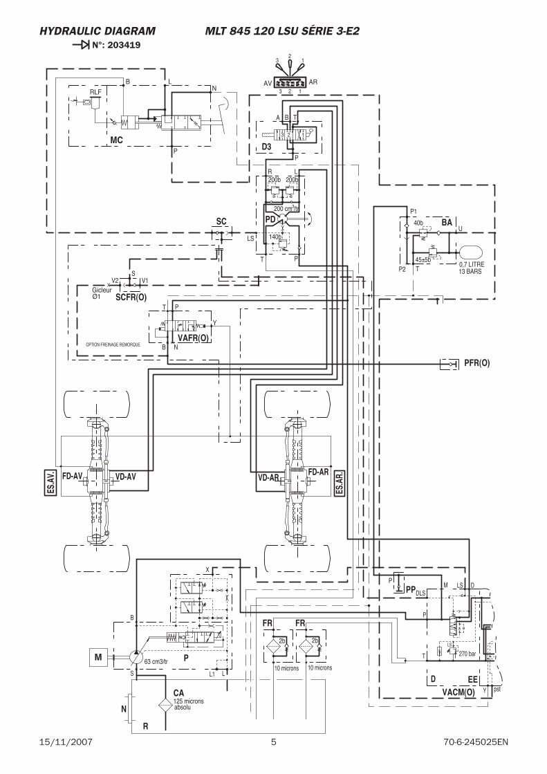
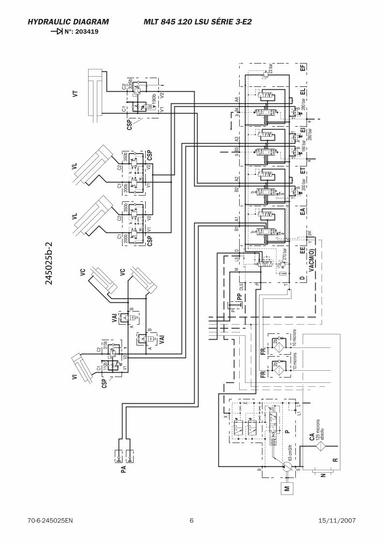
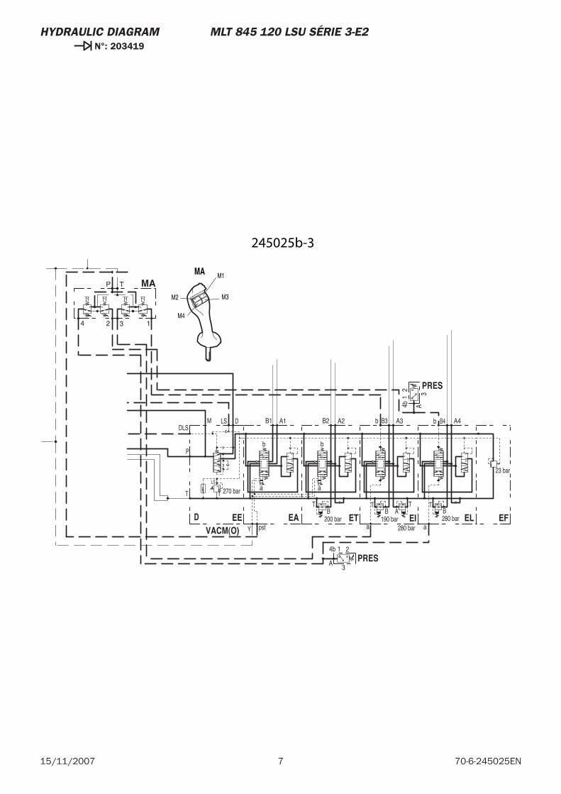
HYDRAULIC DIAGRAM MLT 845 120 LSU SÉRIE 3-E2 N°: 203419
63 cm3/tr
X
B
LS L1
T
LS
DLS
T
P
M LS D
Y pst
270 barPM
VACM(O)EED
CA
N
FD-ARVD-AR
ES.A
V.
ES.A
R.FD-AV VD-AV
SC
R
FR
PD
D3
BA
FR
VAFR(O)
SCFR(O)
PFR(O)
PP
MC
125 microns absolu
200b
32
1
3 2 1
10 microns
2b
LS
T P
R L
P
3 2 1
TA B
200b
140b
200 cm /tr3
P2 T45±5b
40b
P1
U
13 BARS0,7 LITRE
ARAV
10 microns
2b
Y
T P
NB
V1GicleurØ1
V2S
OPTION FREINAGE REMORQUE
P
RLF
B LN
P
6 15/11/200770-6-245025EN
HYDRAULIC DIAGRAM MLT 845 120 LSU SÉRIE 3-E2 N°: 203419
63 c
m3/
tr
bb
aa
a
bB4
A4
a
bB3
A3B2
A2B1
A1
V2V1C1
C2
C1
C2
V1
V2
X
B
LS
L1
T
LS
23 b
ar
DLS
280
bar
BT
280
bar
AT
190
bar
BT
200
bar
BT
TP
MLS
D
Yps
t
270
bar
PM
VACM
(O)EE
EFEL
EIET
EAD
CA
VC
N
CSP
VIVL
R
VT
FR
PA
FR
VC
VAI
VAI
VL
CSP
PP
CSP
CSP
125
mic
rons
abs
olu
C1
C2
10 m
icron
s
2b
V2V1
350b
10 m
icron
s
2b
BA
BA
w
k
C1
C2 V2
V1
350b
w
k20
0b20
0b
P
315b
110b
335b
190b
2450
25b
-2
7 70-6-245025EN15/11/2007
HYDRAULIC DIAGRAM MLT 845 120 LSU SÉRIE 3-E2 N°: 203419
bb
aa
a
b B4 A4
a
b B3 A3B2 A2B1 A1
T
LS
23 bar
DLS
280 barB
T
280 bar
AT
190 barB
T
200 barB
T
T
P
M LS D
Y pst
270 bar
VACM(O)EE EFELEIETEAD
MA
PRES
PRES
321
4b A
T
4 2 13
P
4b
3
1 2
A
MA M1
M2 M3
M4
245025b-3

8 15/11/200770-6-245025EN
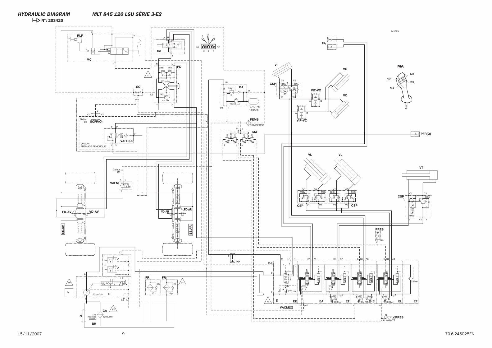
915/11/2007 70-6-245025EN
FEMS
P
VACM(O)
EE EFELEIETEAD
CA
MA
VC
N
FD-ARVD-ARFD-AV VD-AV
SC
CSP
VL
BH
VT
FR
PD
D3
BA
PA
FR
VIP-VC
VIT-VC
VL
CSP
PRES
PRES
SCFR(O)
PFR(O)
PP
CSP
MC
CSP
VAFM
RLF
ES
.AV.
ES
.AR
.
VIVC
MA
M3
M1
M4
M2
315b110b
B LN
P
335b
190b
FT
FT
FT
FT
FT
M
VAFR(O)
10 MICRONS
Gicleur Ø1
100 L/mn
321
4bA
T
4 2 13
P
125microns
absolu
200b
32
1
3 2 1
C1 C2
10 μ
2b
LS
T P
R L
P
3 2 1
TA B
200b
140b
200 cm3/tr
V2V1
350b
P2 T
45±5b
35b
P1
U
13 BARS0,7 LITRE
ARAV
10 μ
2b
BA
BA
wk
C1 C2
V2V1
350b
wk
200b200b
4b
3
1 2
A
Y
T P
NB
V1
Gicleur Ø1
V2S
OPTIONFREINAGE REMORQUE
P
63 cm3/tr
bb
aa
a
b B4 A4
a
b B3 A3B2 A2B1 A1
V2V1
C1 C2
C1 C2
V1 V2
13
2
X
B
LS
L1
T
LS
23 bar
DLS
280 barB
T
280b.A
T
190b.B
T
200 barB
T
T
P
M LS D
Y pst
270 bar
245025f
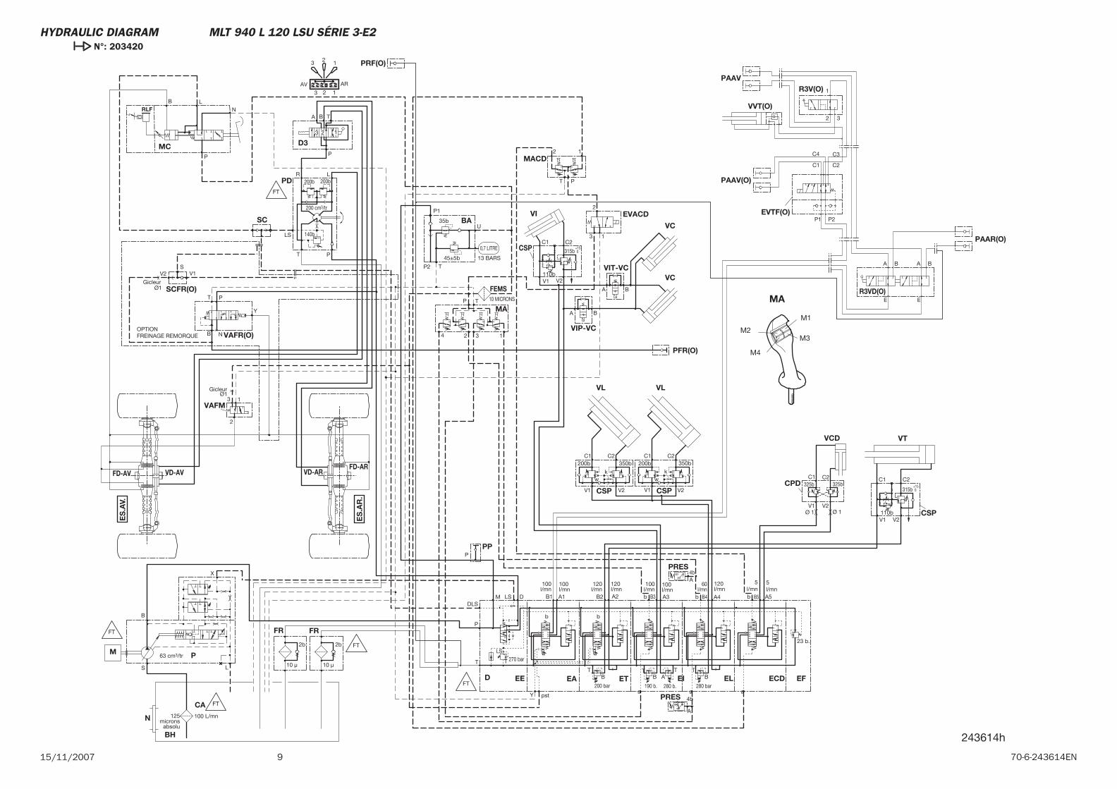
HYDRAULIC DIAGRAM MLT 845 120 LSU SÉRIE 3-E2 N°: 203420

10 15/11/200770-6-245025EN
MT 940 L Turbo Série 3-E2
15 / 11 / 2007
HYDRAULIC DIAGRAM
70-6-245209 EN

2 15/11/200770-6-245209EN
3 70-6-245209EN15/11/2007
-HYDRAULIC DIAGRAM
MT 940 L Turbo Série 3-E2 Légende . . . . . . . . . . . . . . . . . 4
MT 940 L Turbo Série 3-E2 N°: 203419. . . . . . . . . . . 5
MT 940 L Turbo Série 3-E2 N°: 203420 . . . . . . . . . . . 7
CONTENTS
4 15/11/200770-6-245209EN
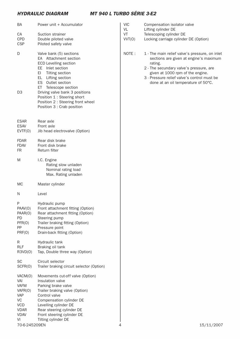
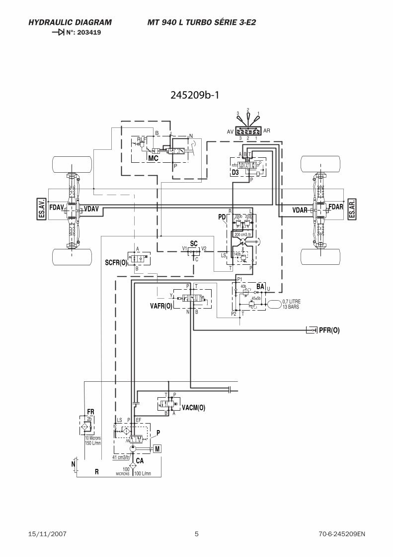
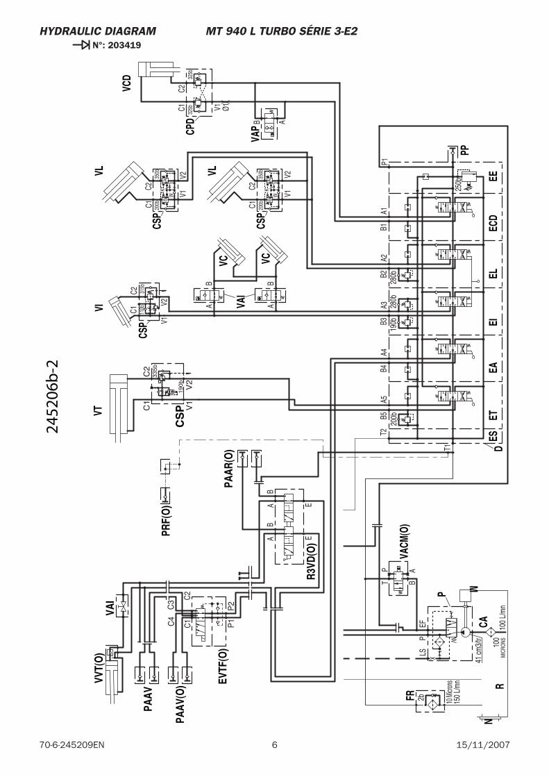
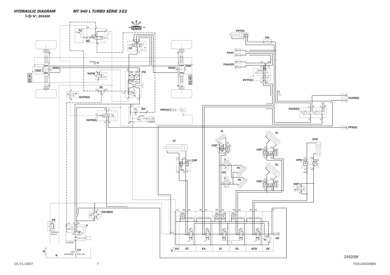
BA Power unit + Accumulator
CA Suction strainerCPD Double piloted valveCSP Piloted safety valve
D Valve bank (5) sections EA Attachment section ECD Levelling section EE Inlet section EI Tilting section EL Lifting section ES Outlet section ET Telescope sectionD3 Driving valve bank 3 positions Position 1 : Steering short Position 2 : Steering front wheel Position 3 : Crab position
ESAR Rear axleESAV Front axleEVTF(O) Jib head electrovalve (Option)
FDAR Rear disk brakeFDAV Front disk brakeFR Return fi lter
M I.C. Engine Rating slow unladen Nominal rating load Max. Rating unladen
MC Master cylinder
N Level
P Hydraulic pumpPAAV(O) Front attachment fi tting (Option)PAAR(O) Rear attachment fi tting (Option)PD Steering pumpPFR(O) Trailer braking fi tting (Option)PP Pressure pointPRF(O) Drain-back fi tting (Option)
R Hydraulic tankRLF Braking oil tankR3VD(O) Tap, Double three way (Option)
SC Circuit selectorSCFR(O) Trailer braking circuit selector (Option)
VACM(O) Movements cut-off valve (Option) VAI Insulation valve VAFM Parking brake valve VAFR(O) Trailer braking valve (Option) VAP Control valveVC Compensation cylinder DEVCD Levelling cylinder DEVDAR Rear steering cylinder DEVDAV Front steering cylinder DEVI Tilting cylinder DE
VIC Compensation isolator valve VL Lifting cylinder DEVT Telescoping cylinder DEVVT(O) Locking carriage cylinder DE (Option)
NOTE : 1 - The main relief valve’s pressure, on inlet sections are given at engine’s maximum rating.
2 - The secundary valve’s pressure, are given at 1000 rpm of the engine.
3 - Pressure relief valve’s control must be done at an oil temperature of 50°C.
HYDRAULIC DIAGRAM MT 940 L TURBO SÉRIE 3-E2
5 70-6-245209EN15/11/2007
HYDRAULIC DIAGRAM MT 940 L TURBO SÉRIE 3-E2 N°: 203419
150 L/mn
41 cm3/tr
10 Microns
2b EFLS P
100MICRONS 100 L/mn
0,7 LITRE13 BARS
U
P140b
45±5b
TP2
200 cm3 /tr
140b
200b
BA T
123
P
LR
PT
LSV2V1
200b
C
B
TP
N
B
A
T
B A
P
MC
N CA
P
R
FR
M
BA
D3
PD
SC
VDAVFDAV VDAR FDAR
SCFR(O)
VAFR(O)
PFR(O)
VACM(O)
P
NLBRLF
Y
ES.A
V.
ES.A
R.
32
1
3 2 1
ARAV
245209b-1
6 15/11/200770-6-245209EN
HYDRAULIC DIAGRAM MT 940 L TURBO SÉRIE 3-E2 N°: 203419
V2
V1
C2
C1
B A
C232
5bC1 325b V1
A5B5
T1
BA
BA
V2
C235
0bK
V1W
C1 200b
200b
250b
P1A1
B1T2
B4A4
B319
0bA3
B2A2
280b
280b
150 L
/mn
41 cm
3/tr
10 M
icron
s
2bEF
LSP
100
MIC
RONS
100
L/m
n
V2
C235
0bK
V1W
C1 200b
Ø1
V2V1
C1C2
C1
C2
C3
C4
P1
P2
E
BA
BA E
T BAP
AB
AB
CS
P
VAPCP
D
VCD
ECD
VAI
CSP
N
VT
VL
VCCS
P
VLVI
VC
CAET
EE
PP
ESD
EAEI
EL
P
R
FR
M
CSP
PRF(
O)
VAI
VVT(
O)
PAAV
PAAV
(O) EV
TF(O
)
R3VD
(O)
PAAR
(O)
VACM
(O)
190b
335b
110b
315b
2452
06b
-2
715/11/2007 70-6-245209EN
VAFM
CSP
MC
VAP
CPD
VCD
ECD
VIC
CSP
N
VT
VL
VCCSP
VLVI
VC
CA ET EE
PP
ESD
EA EI EL
P
R
FR
BA
D3
PD
SC
VDAVFDAV
VDARFDAR
CSP
Gicleur
SCFR(O)
VAFR(O)
PFR(O)
PRF(O)
VAI
VVT(O)
PAAV
PAAV(O)
EVTF(O)
R3VD(O)
PAAR(O)
VACM(O)
13
2
V2V1
C2C1
B
A
C2325b
V2
C1325b
V1
A5B5
T1
BA
BA
V2
C2350b
K
V1
W
C1200b
200b
250b
P1A1B1T2 B4 A4 B3
190b
A3 B2 A2
280b 280b
150 L/mn
41 cm3/tr
10 Microns
2b EFLS P
140MICRONS 100 L/mn
0,7 LITRE
13 BARS
U
P1
35b
45±5b
TP2
200 cm3/tr
140b
200b
BA T
123
P
LR
PT
LS
V2V1
200b
ARAV123
12
3
V2
C2350b
K
V1
W
C1200b
C
V2V1
C1 C2
B
TP
N
B
A
C1 C2
C3C4
P1 P2
E
BA BA
E
T
B A
P
AB
AB
190b
335b
P
N
LBRLF
110b 315b
Y
ES
.AV.
ES
.AR
.
Ø1
Ø1
245209f
HYDRAULIC DIAGRAM MT 940 L TURBO SÉRIE 3-E2 N°: 203420

8 15/11/200770-6-245209EN
MLT 940 L 120 LSU Série 3-E2
15 / 11 / 2007
HYDRAULIC DIAGRAM
70-6-243614 EN

2 15/11/200770-6-243614EN
3 70-6-243614EN15/11/2007
-HYDRAULIC DIAGRAM
MLT 940 L 120 LSU Série 3-E2 Légende . . . . . . . . . . . . . . . . . 4
MLT 940 L 120 LSU Série 3-E2 N°: 203419. . . . . . . . . . . 5
MLT 940 L 120 LSU Série 3-E2 N°: 203420 . . . . . . . . . . . 7
CONTENTS
4 15/11/200770-6-243614EN
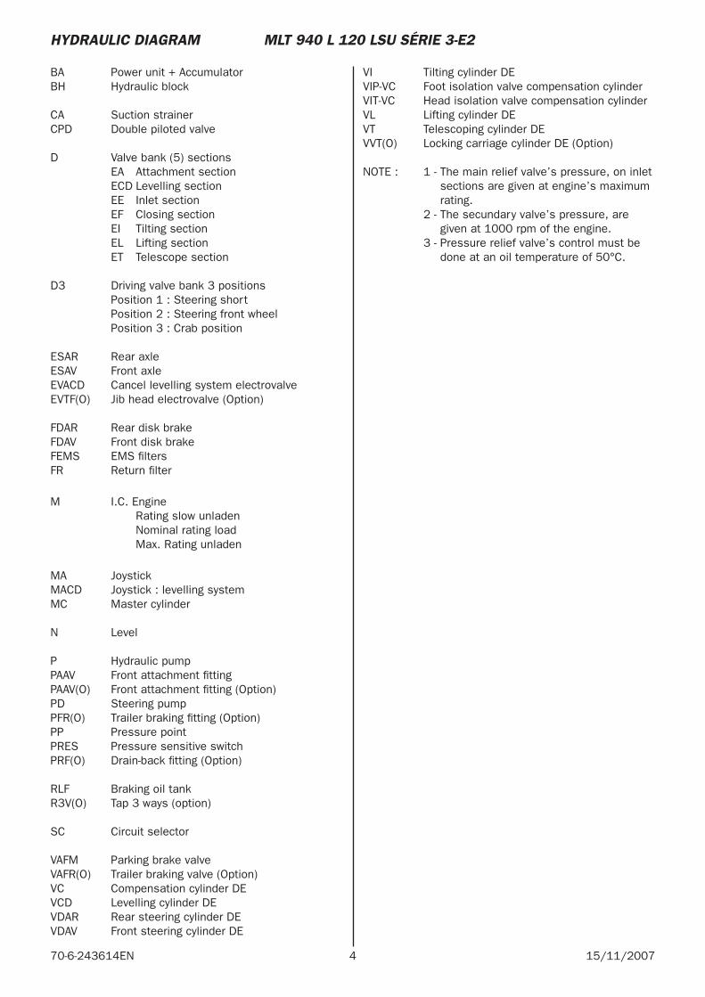
B A Power unit + AccumulatorBH Hydraulic block
CA Suction strainerCPD Double piloted valve
D Valve bank (5) sections EA Attachment section ECD Levelling section EE Inlet section EF Closing section EI Tilting section EL Lifting section ET Telescope section D3 Driving valve bank 3 positions Position 1 : Steering short Position 2 : Steering front wheel Position 3 : Crab position
ESAR Rear axleESAV Front axleEVACD Cancel levelling system electrovalveEVTF(O) Jib head electrovalve (Option)
FDAR Rear disk brakeFDAV Front disk brakeFEMS EMS fi ltersFR Return fi lter
M I.C. Engine Rating slow unladen Nominal rating load Max. Rating unladen
MA JoystickMACD Joystick : levelling systemMC Master cylinder
N Level
P Hydraulic pumpPAAV Front attachment fi ttingPAAV(O) Front attachment fi tting (Option)PD Steering pumpPFR(O) Trailer braking fi tting (Option) PP Pressure pointPRES Pressure sensitive switchPRF(O) Drain-back fi tting (Option)
RLF Braking oil tank R3V(O) Tap 3 ways (option)
SC Circuit selector
VAFM Parking brake valveVAFR(O) Trailer braking valve (Option)VC Compensation cylinder DEVCD Levelling cylinder DEVDAR Rear steering cylinder DEVDAV Front steering cylinder DE
VI Tilting cylinder DEVIP-VC Foot isolation valve compensation cylinderVIT-VC Head isolation valve compensation cylinderVL Lifting cylinder DEVT Telescoping cylinder DEVVT(O) Locking carriage cylinder DE (Option)
NOTE : 1 - The main relief valve’s pressure, on inlet sections are given at engine’s maximum rating.
2 - The secundary valve’s pressure, are given at 1000 rpm of the engine.
3 - Pressure relief valve’s control must be done at an oil temperature of 50°C.
HYDRAULIC DIAGRAM MLT 940 L 120 LSU SÉRIE 3-E2
5 70-6-243614EN15/11/2007
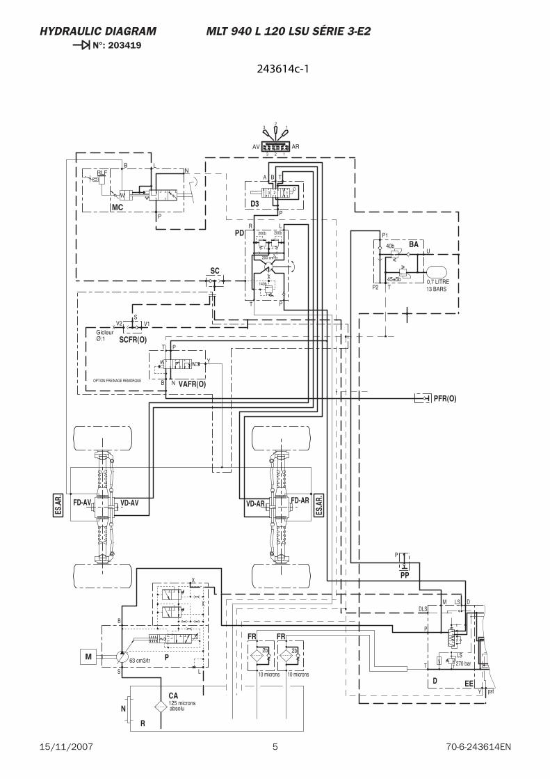
HYDRAULIC DIAGRAM MLT 940 L 120 LSU SÉRIE 3-E2 N°: 203419
EED
MC
PP
PFR(O)
SCFR(O)
VAFR(O)
FR
BA
D3
PD
FR
R
SC
VD-AVFD-AV
ES.A
R.
ES.A
R.
VD-AR FD-AR
N
CA
PM
P
NLB
RLF
OPTION FREINAGE REMORQUE
SV2
GicleurØ:1
V1
B N
PT
Y
2b
10 microns
AV AR
0,7 LITRE13 BARS
U
P1
40b
45±5bTP2
3200 cm /tr
140b
200b
BA T
123
P
LR
PT
2b
10 microns
123
12
3
200b
125 microns absolu
P
63 cm3/trT
LS
DLS
T
P
M LS D
Y pst
270 bar
X
B
LS
243614c-1
6 15/11/200770-6-243614EN
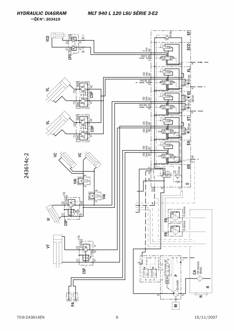
HYDRAULIC DIAGRAM MLT 940 L 120 LSU SÉRIE 3-E2 N°: 203419
VAI
VAI
EEEF
ELEI
ETEA
D
CPD
VCD
CSPVL
VC
FR
PA
FR
VT
R
VLVI
CSP
N
VC
CA
CSP
CSP
PM
ECD
BA
BA
V1
325bC1
V2
325b
C2
Ø: 1
Ø: 1
200b
200b
k
w
350b
V1V2
C2
C1
k
w
2b
10 m
icron
s
350b
V1V2
2b
10 m
icron
s
C2
C1
125
mic
rons
abs
olu
110b
315b
C2C1 V1
V2
+15 0
110b
315b
C2C1 V1
V2
+15
0
100
100
120
120
512
010
0l/m
nl/m
nl/m
nl/m
nl/m
n
5 l/mn
l/mn
60 l/mn
100 l/mn
l/mn
bb
aa
a
bB4
A4
a
bB3
A3B2
A2B1
A1
63 c
m3/
tr
A5B5
b
a
T
LS
23 b
ar
DLS
280
bar
BT
280
bar
AT
190
bar
BT
200
bar
BT
TP
MLS
D
Yps
t
270
bar
X
B
LS
2436
14c-
2
7 70-6-243614EN15/11/2007
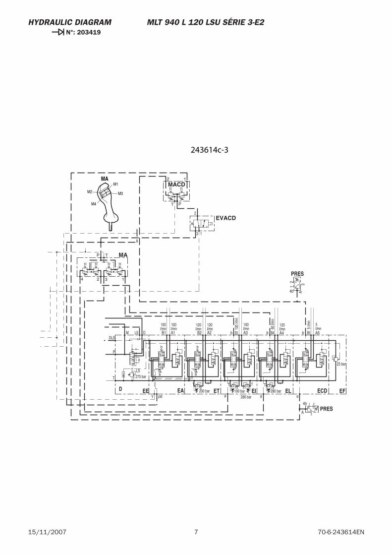
HYDRAULIC DIAGRAM MLT 940 L 120 LSU SÉRIE 3-E2 N°: 203419
PRES
PRES
EE EFELEIETEAD
EVACD
MACD
MA
ECD
2 314b A
A
21
3
4b
T
2 1
P
P
3 124
T
13
2
100 100 120 120 5120100l/mnl/mn l/mnl/mn l/mn5
l/mn
l/mn60 l/m
n
100
l/mn
l/mn
bb
aa
a
b B4 A4
a
b B3 A3B2 A2B1 A1 A5B5b
a
T
LS
23 bar
DLS
280 barB
T
280 bar
AT
190 barB
T
200 barB
TT
P
M LS D
Y pst
270 bar
MA
M2
M1
M3
M4
243614c-3

8 15/11/200770-6-243614EN
915/11/2007 70-6-243614EN
ES
.AV.
ES
.AR
.
FEMS
PAAV
PRES
VAFM
VIP-VC
VIT-VC
PRES
EE EFELEIETEAD
MC
EVACD
MACD
CPD
VCD
PP
PFR(O)
SCFR(O)
VAFR(O)
CSP
VL
VC
FR
BA
D3
PD
FR
VT
BH
VL
VI
CSP
SC
VD-AVFD-AV VD-ARFD-AR
N
VC
MA
CA
CSP
CSP
PM
ECD
R3V(O)
R3VD(O)
PAAR(O)
EVTF(O)
PAAV(O)
VVT(O)
PRF(O)
10 MICRONS
4b3 12
A
100 L/mn
BA
BA
A2 13
4b
P
NLB
RLF
T
2 1
P
V1
325bC1
V2
325bC2
Ø 1 Ø 1
OPTIONFREINAGE REMORQUE
SV2
Gicleur Ø1
V1
B N
PT
Y
200b 200bk
w
350b
V1 V2
C2C1
kw
2b
10 μ
AV AR
0,7 LITRE
13 BARS
U
P1
35b
45±5b
TP2
350b
V1 V2
200 cm3/tr
140b
200b
BA T
123
P
LR
PT
LS
2b
10 μ
C2C1
123
123
200b
125microns
absolu
P
3 124
T
110b
C2C1
V1 V2
110b
C2C1
V1 V2
315b+150
Gicleur Ø1
13
2
P
100l/mn
100l/mn
100l/mn
100l/mn
120l/mn
120l/mn
5l/mn
5l/mn
60l/mn
120l/mn
2
3 1
MA
M3
M1
M4
M2
bb
aa
a
b B4 A4
a
b B3 A3B2 A2B1 A1
63 cm3/tr
A5B5b
a
32
1
E
BA BA
E
P2P1
C4 C3
C2C1
T
LS
23 b.
DLS
280 bar
BT
280 b.
AT
190 b.
BT
200 bar
BT
T
P
M LS D
Y pst
270 bar
X
B
LS
FT
FT
FT
FT
FT
315b+150
243614h
HYDRAULIC DIAGRAM MLT 940 L 120 LSU SÉRIE 3-E2 N°: 203420

10 15/11/200770-6-24314EN
MT 1235 S Série 3-E2MT 1235 S Turbo Série 3-E2
15 / 11 / 2001
HYDRAULIC DIAGRAM
70-6-255786 EN

2 15/11/200770-6-255786EN
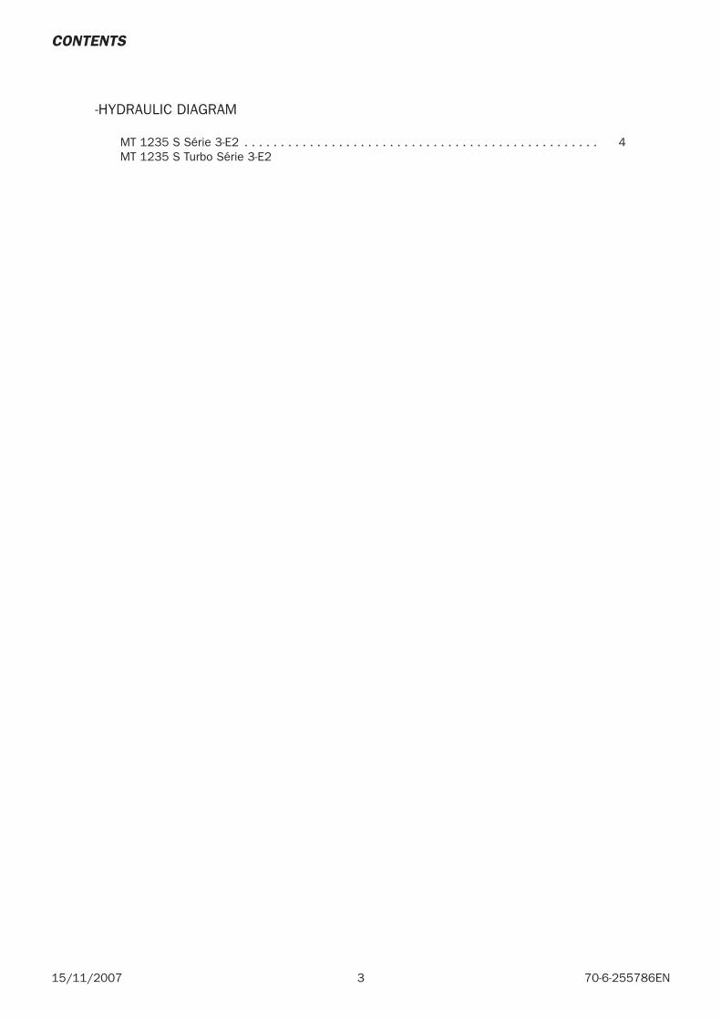
3 70-6-255786EN15/11/2007
-HYDRAULIC DIAGRAM
MT 1235 S Série 3-E2 . . . . . . . . . . . . . . . . . . . . . . . . . . . . . . . . . . . . . . . . . . . . . . . . . 4 MT 1235 S Turbo Série 3-E2
CONTENTS
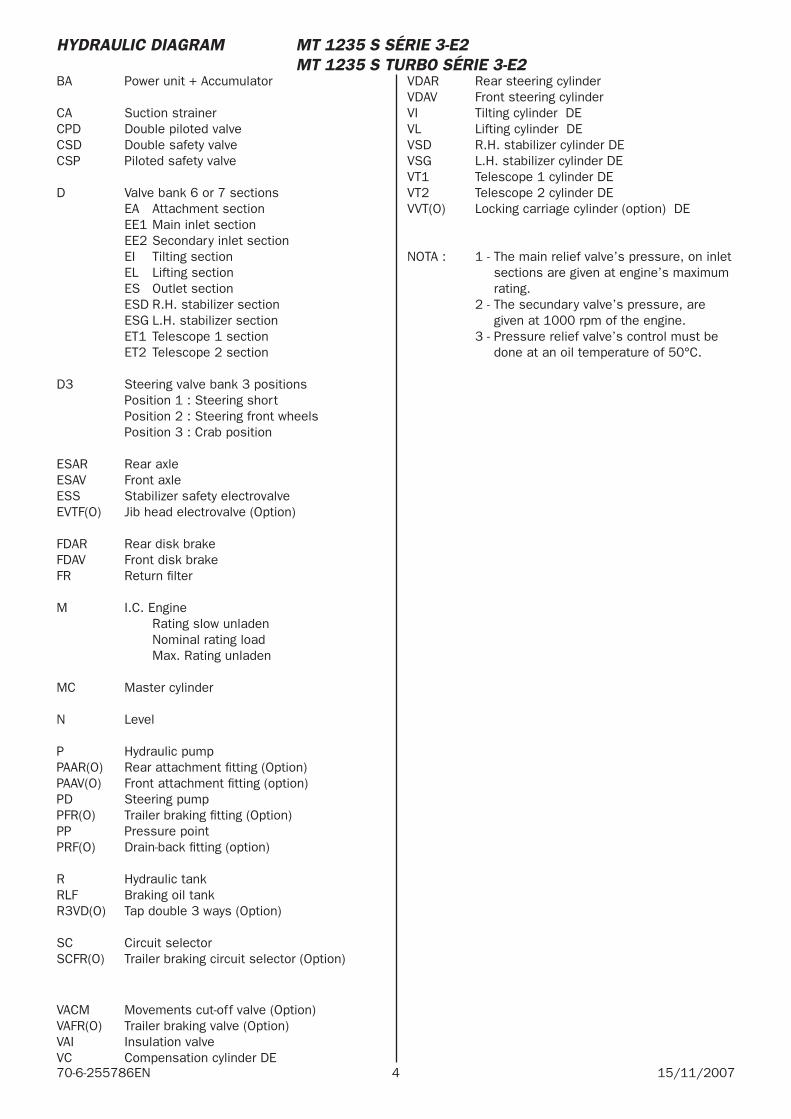
4 15/11/200770-6-255786EN
BA Power unit + Accumulator
CA Suction strainerCPD Double piloted valveCSD Double safety valveCSP Piloted safety valve
D Valve bank 6 or 7 sections EA Attachment section EE1 Main inlet section EE2 Secondary inlet section EI Tilting section EL Lifting section ES Outlet section ESD R.H. stabilizer section ESG L.H. stabilizer section ET1 Telescope 1 section ET2 Telescope 2 section
D3 Steering valve bank 3 positions Position 1 : Steering short Position 2 : Steering front wheels Position 3 : Crab position
ESAR Rear axleESAV Front axleESS Stabilizer safety electrovalveEVTF(O) Jib head electrovalve (Option)
FDAR Rear disk brakeFDAV Front disk brakeFR Return fi lter
M I.C. Engine Rating slow unladen Nominal rating load Max. Rating unladen
MC Master cylinder
N Level
P Hydraulic pumpPAAR(O) Rear attachment fi tting (Option)PAAV(O) Front attachment fi tting (option)PD Steering pumpPFR(O) Trailer braking fi tting (Option)PP Pressure point PRF(O) Drain-back fi tting (option)
R Hydraulic tankRLF Braking oil tankR3VD(O) Tap double 3 ways (Option)
SC Circuit selectorSCFR(O) Trailer braking circuit selector (Option)
VACM Movements cut-off valve (Option)VAFR(O) Trailer braking valve (Option)VAI Insulation valve VC Compensation cylinder DE
VDAR Rear steering cylinderVDAV Front steering cylinderVI Tilting cylinder DEVL Lifting cylinder DEVSD R.H. stabilizer cylinder DEVSG L.H. stabilizer cylinder DEVT1 Telescope 1 cylinder DEVT2 Telescope 2 cylinder DEVVT(O) Locking carriage cylinder (option) DE
NOTA : 1 - The main relief valve’s pressure, on inlet sections are given at engine’s maximum rating.
2 - The secundary valve’s pressure, are given at 1000 rpm of the engine.
3 - Pressure relief valve’s control must be done at an oil temperature of 50°C.
HYDRAULIC DIAGRAM MT 1235 S SÉRIE 3-E2 MT 1235 S TURBO SÉRIE 3-E2
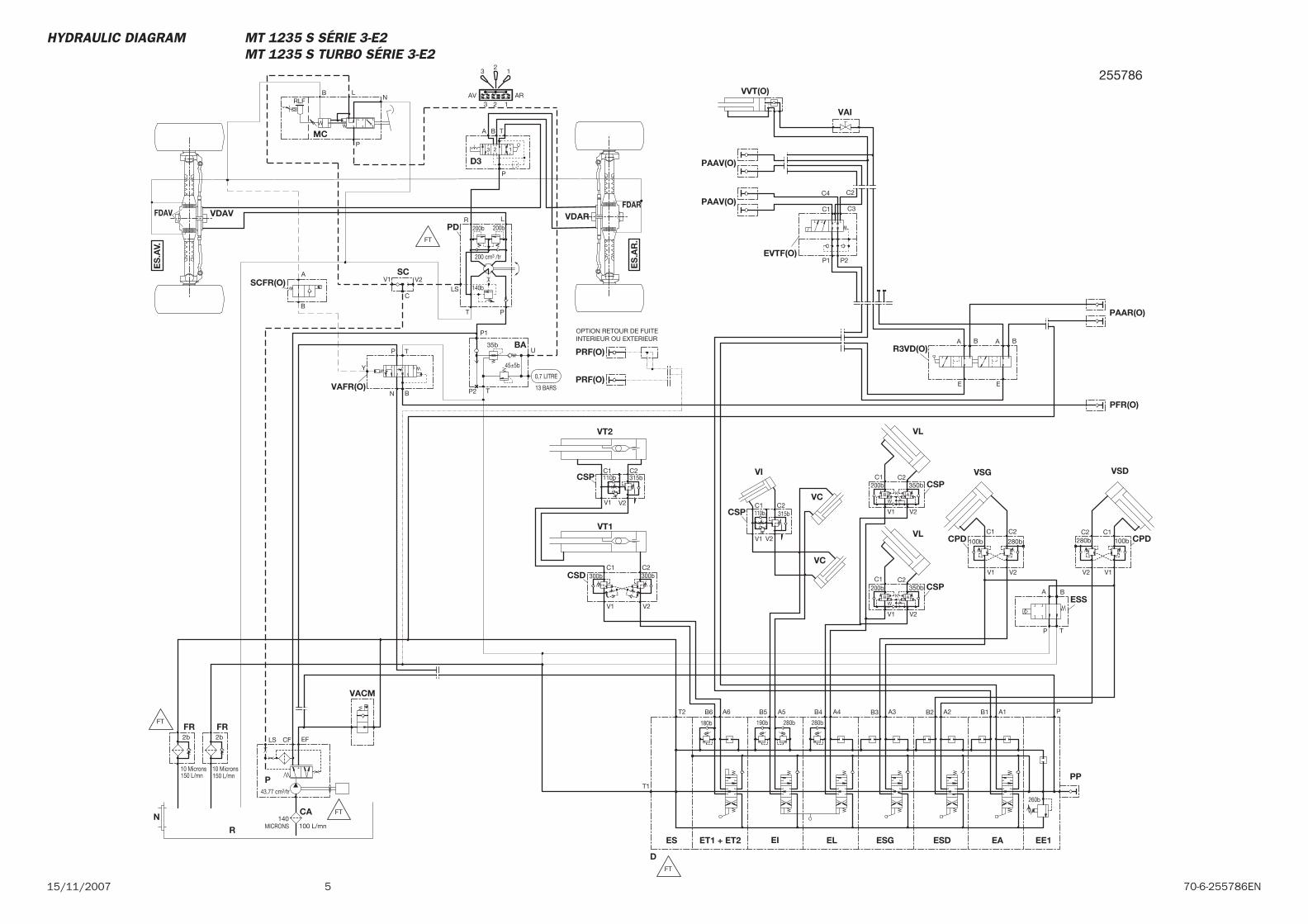
515/11/2007 70-6-255786EN
EA
MC
CSP
CSP
CSD
VT2
VT1
ESS
VSD
CPD
FDARVDARFDAV VDAV
SC
PD
D3
BA
FRFR
R
P
ESDEL ESGEIES
PP
EE1ET1 + ET2
CA
CPD
VSG
VC
VI
VL
CSP
VC
VL
CSP
N
D
SCFR(O)
VAFR(O)
PFR(O)
PRF(O)
PRF(O)
VAI
VVT(O)
PAAV(O)
PAAV(O)
EVTF(O)
R3VD(O)
PAAR(O)
VACM
B1 A1
T
T1
C2C1
V1 V2
C2C1
V1 V2
A3B3A6B6
300b
V1 V2
C1 C2300b
BA
P
C
C2 C1280b
V2 V1
100b
200bC1
W
V1
K
350bC2
V2
32
1
3 2 1AV AR
200b
V1 V2
LS
T P
R L
P
3 2 1
TA B
200b
140b
200 cm3 /tr
P2 T
45±5b
35b
P1
U
13 BARS
0,7 LITRE
100 L/mn140
MICRONS
CFLS EF2b
10 Microns
2b
10 Microns
43.77 cm3/tr
150 L/mn 150 L/mn
A2B2A4
280b
B4
280b
A5B5
190b
T2 P
260b
180b
C2C1
280b
V2V1
100b
200bC1
W
V1
K
350bC2
V2
B
TP
N
B
A
OPTION RETOUR DE FUITEINTERIEUR OU EXTERIEUR
C1
C2
C3
C4
P1 P2
E
BA BA
E
B A
B A
P
NLB
RLF
110b
110b 315b
315b
FT
FT
FT
FT
Y
ES
.AV.
ES
.AR
.
255786
HYDRAULIC DIAGRAM MT 1235 S SÉRIE 3-E2 MT 1235 S TURBO SÉRIE 3-E2

6 15/11/200770-6-255786EN

MT 1240 L Turbo Série 3-E2
15 / 11 / 2007
HYDRAULIC DIAGRAM
70-6-245183 EN

2 15/11/200770-6-245183EN
3 70-6-245183EN15/11/2007
-HYDRAULIC DIAGRAM
MT 1240 L Turbo Série 3-E2 Légende . . . . . . . . . . . . . . . . . 4
MT 1240 L Turbo Série 3-E2 . . . . . . . . . . . . . . . . . . . . . . . 5
CONTENTS
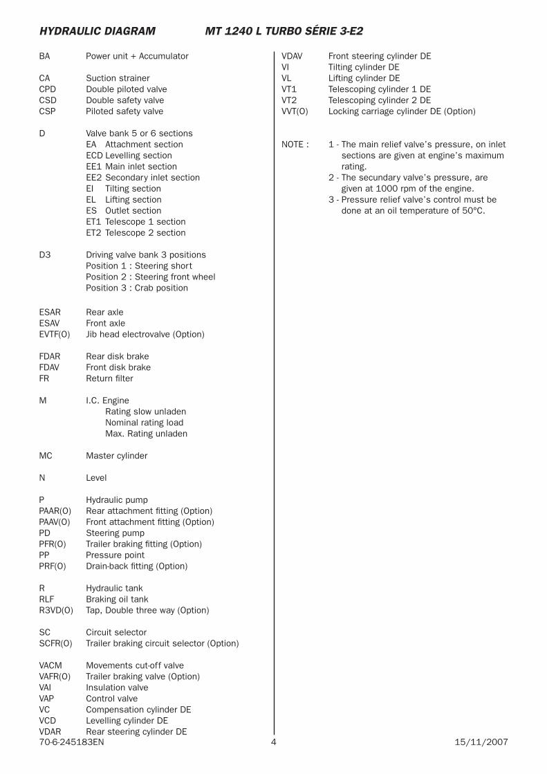
4 15/11/200770-6-245183EN
BA Power unit + Accumulator
CA Suction strainerCPD Double piloted valveCSD Double safety valveCSP Piloted safety valve
D Valve bank 5 or 6 sections EA Attachment section ECD Levelling section EE1 Main inlet section EE2 Secondary inlet section EI Tilting section EL Lifting section ES Outlet section ET1 Telescope 1 section ET2 Telescope 2 section
D3 Driving valve bank 3 positions Position 1 : Steering short Position 2 : Steering front wheel Position 3 : Crab position
ESAR Rear axleESAV Front axleEVTF(O) Jib head electrovalve (Option)
FDAR Rear disk brakeFDAV Front disk brakeFR Return fi lter
M I.C. Engine Rating slow unladen Nominal rating load Max. Rating unladen
MC Master cylinder
N Level
P Hydraulic pumpPAAR(O) Rear attachment fi tting (Option)PAAV(O) Front attachment fi tting (Option) PD Steering pumpPFR(O) Trailer braking fi tting (Option)PP Pressure pointPRF(O) Drain-back fi tting (Option)
R Hydraulic tankRLF Braking oil tankR3VD(O) Tap, Double three way (Option)
SC Circuit selectorSCFR(O) Trailer braking circuit selector (Option)
VACM Movements cut-off valveVAFR(O) Trailer braking valve (Option)VAI Insulation valveVAP Control valveVC Compensation cylinder DEVCD Levelling cylinder DEVDAR Rear steering cylinder DE
VDAV Front steering cylinder DEVI Tilting cylinder DEVL Lifting cylinder DEVT1 Telescoping cylinder 1 DEVT2 Telescoping cylinder 2 DEVVT(O) Locking carriage cylinder DE (Option)
NOTE : 1 - The main relief valve’s pressure, on inlet sections are given at engine’s maximum rating.
2 - The secundary valve’s pressure, are given at 1000 rpm of the engine.
3 - Pressure relief valve’s control must be done at an oil temperature of 50°C.
HYDRAULIC DIAGRAM MT 1240 L TURBO SÉRIE 3-E2
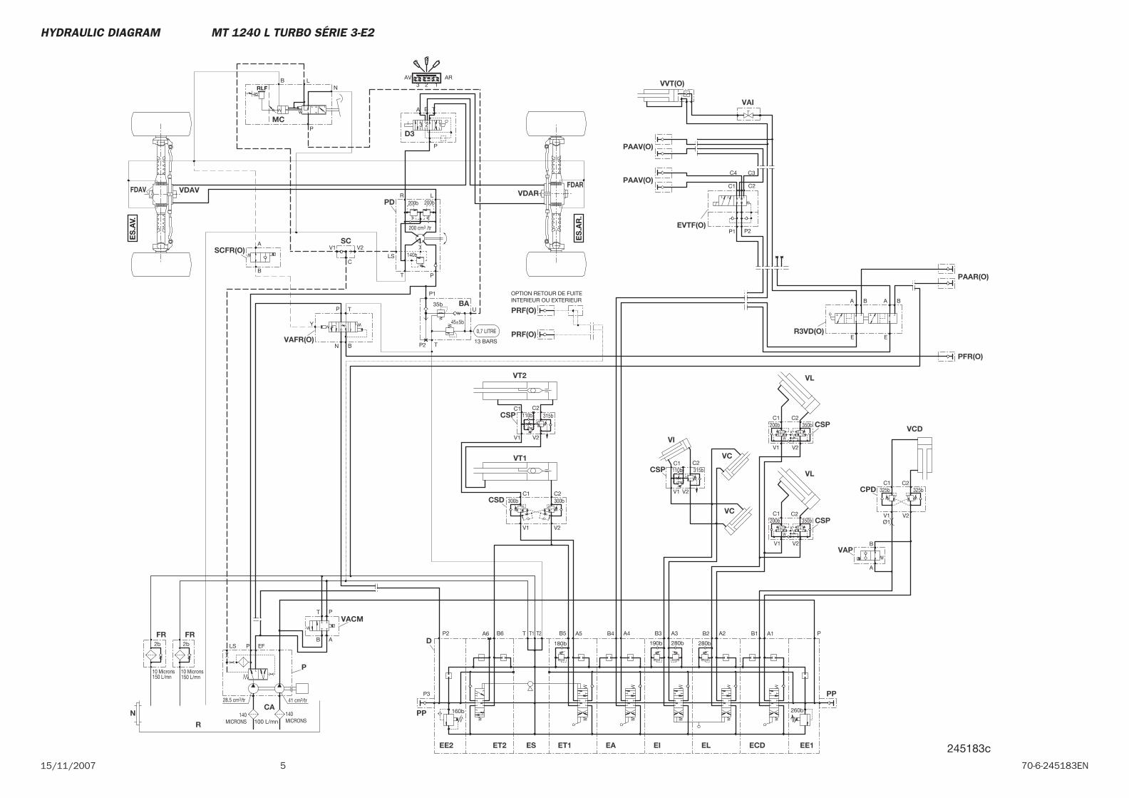
515/11/2007 70-6-245183EN
CSP
CSP
VCD
CPD
VAP
N
CSP
VL
VCCSP
VL
VI
VC
CA
ET1 EE1
PP
PP
EE2 ET2 ES
D
EI EL
P
R
FR FR
BA
D3
PD
SC
VDAVFDAV VDARFDAR
VT1
VT2
CSD
ECDEA
MC
VACM
PAAR(O)
R3VD(O)
EVTF(O)
PAAV(O)
PAAV(O)
VVT(O)
VAI
PRF(O)
PRF(O)
PFR(O)
VAFR(O)
SCFR(O)
C2C1
V1 V2
C2C1
V1 V2
V1
325bC1
V2
325bC2
B
A
V2
C2350b
K
V1
W
C1200b
180b
260b
PA1B1
P3
160b
P2 A6 T1T T2
190b
B4 A4
280b
B3
280b
A3 B2 A2B6
150 L/mn150 L/mn
41 cm3/tr28.5 cm3/tr
10 Microns
2b
10 Microns
2b EFLS P
140MICRONS
140MICRONS100 L/mn
0,7 LITRE
13 BARS
U
P1
35b
45±5b
TP2
200 cm3 /tr
140b
200b
BA T
123
P
LR
PT
LS
V2V1
200b
ARAV123
12
3
V2
C2350b
K
V1
W
C1200b
C
300bC2C1
V2V1
300b
B5 A5
T
B A
P
E
A BA B
E
P2P1
C4 C3
C2C1
OPTION RETOUR DE FUITEINTERIEUR OU EXTERIEUR
A
B
N
P T
B
AB
AB
110b
110b
RLFB L
N
P
315b
315b
Y
ES
.AV.
ES
.AR
.
Ø1
245183c
HYDRAULIC DIAGRAM MT 1240 L TURBO SÉRIE 3-E2

6 15/11/200770-6-245183EN
MT 1240 L Turbo Ultra Série 3-E2
15 / 11 / 2007
SCHEMA HYDRAULIC DIAGRAM
70-6-242030 EN

2 15/11/200770-6-242030EN

3 70-6-242030EN15/11/2007
-HYDRAULIC DIAGRAM
MT 1240 L Turbo Ultra Série 3-E2 Légende . . . . . . . . . . . . . . . . . 4
MT 1240 L Turbo Ultra Série 3-E2 N°: 206188. . . . . . . . . . . 5
MT 1240 L Turbo Ultra Série 3-E2 N°: 206189 . . . . . . . . . . . 7
CONTENTS
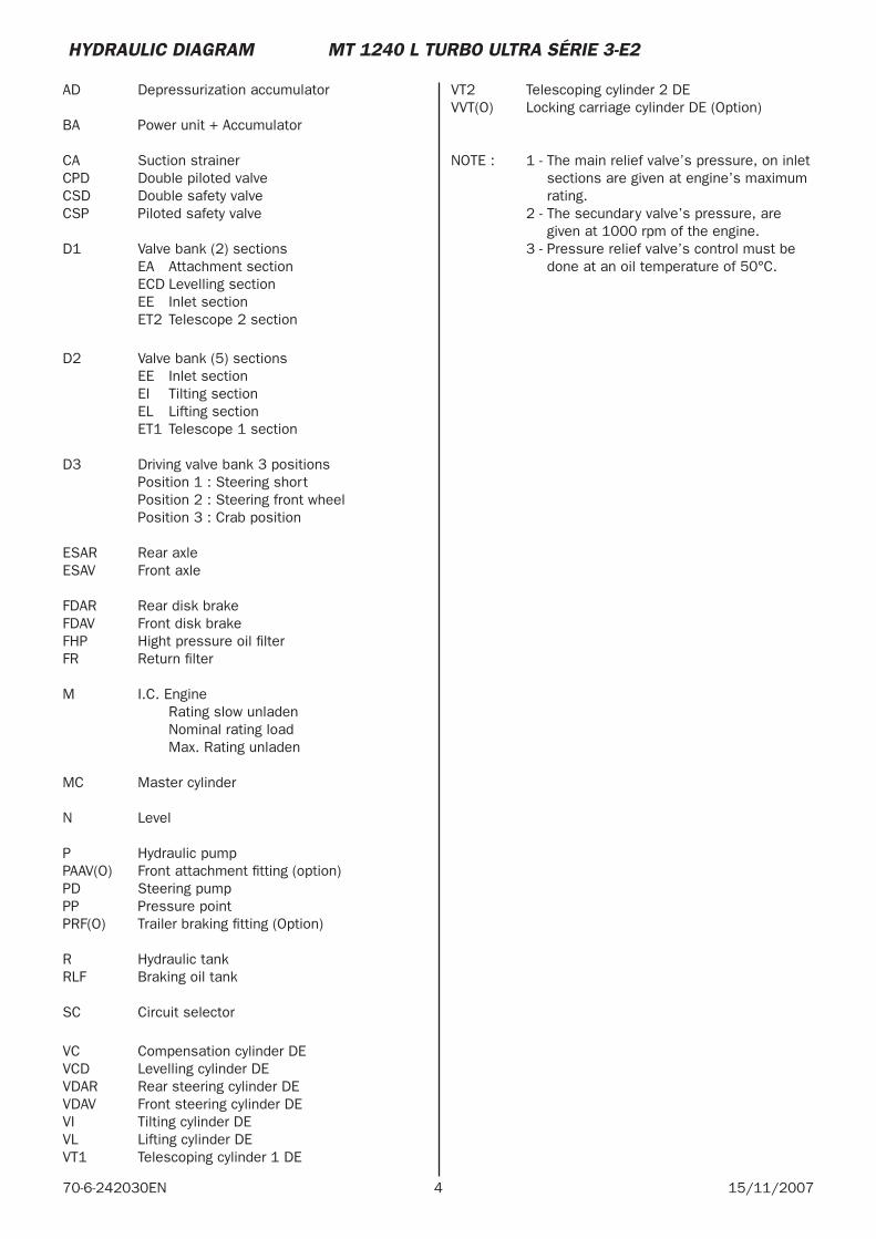
4 15/11/200770-6-242030EN
AD Depressurization accumulator
BA Power unit + Accumulator
CA Suction strainerCPD Double piloted valveCSD Double safety valveCSP Piloted safety valve
D1 Valve bank (2) sections EA Attachment section ECD Levelling section EE Inlet section ET2 Telescope 2 section
D2 Valve bank (5) sections EE Inlet section EI Tilting section EL Lifting section ET1 Telescope 1 section
D3 Driving valve bank 3 positions Position 1 : Steering short Position 2 : Steering front wheel Position 3 : Crab position
ESAR Rear axleESAV Front axle
FDAR Rear disk brakeFDAV Front disk brakeFHP Hight pressure oil fi lterFR Return fi lter
M I.C. Engine Rating slow unladen Nominal rating load Max. Rating unladen
MC Master cylinder
N Level
P Hydraulic pumpPAAV(O) Front attachment fi tting (option)PD Steering pumpPP Pressure pointPRF(O) Trailer braking fi tting (Option)
R Hydraulic tankRLF Braking oil tank
SC Circuit selector
VC Compensation cylinder DEVCD Levelling cylinder DEVDAR Rear steering cylinder DE VDAV Front steering cylinder DEVI Tilting cylinder DEVL Lifting cylinder DEVT1 Telescoping cylinder 1 DE
VT2 Telescoping cylinder 2 DEVVT(O) Locking carriage cylinder DE (Option)
NOTE : 1 - The main relief valve’s pressure, on inlet sections are given at engine’s maximum rating.
2 - The secundary valve’s pressure, are given at 1000 rpm of the engine.
3 - Pressure relief valve’s control must be done at an oil temperature of 50°C.
HYDRAULIC DIAGRAM MT 1240 L TURBO ULTRA SÉRIE 3-E2
5 70-6-242030EN15/11/2007
HYDRAULIC DIAGRAM MT 1240 L TURBO ULTRA SÉRIE 3-E2 N°: 206188
13 BARS0,7 LITRE
U
P140b
45b
TP2
150 L/mn150 L/mn
41 cm3/tr28.5 cm3/tr
10 Microns
2b
10 Microns
2b EFLS P
MICRONS100
70 L/mn
200 cm3 /tr
140b
200b
BA T
123
P
LR
PT
LS
A1
A3A2
B2 B1
V2V1
200b
ARAV123
123
C
A
B
N
P T
B
Y
BA
N CA
P
R
FR FR
M
D3
PD
MC
RLF
SC
VDAVFDAV
ES.A
V.
VDAR
ES.A
R.FDAR
PFR(O)
VAFR(O)
SCFR(O)
242030b-1
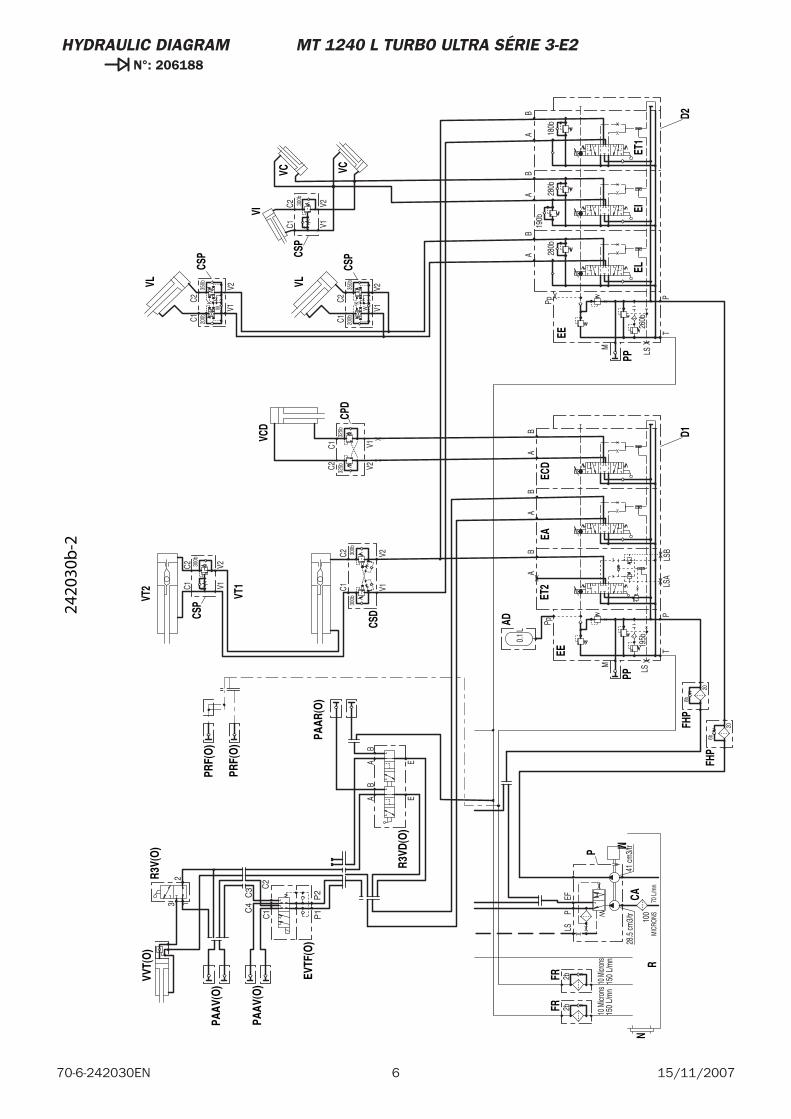
6 15/11/200770-6-242030EN
HYDRAULIC DIAGRAM MT 1240 L TURBO ULTRA SÉRIE 3-E2 N°: 206188
6b
6b
280b
X
X
X
X26
0b
Pp
LS
M
PT
X19
5b
Pp
20
0.1
L
180b
280b
190b
V2
C235
0bK
V1W
V1V2
C1 200b
C1C2 30
0b
AB
150
L/m
n15
0 L/
mn
41 cm
3/tr
28.5
cm3/
tr
10 M
icron
s
2b
10 M
icron
s
2bEF
LSP
MIC
RONS100
70 L
/mn
AB
V2
C235
0bK
V1W
C1 200b
AB
300b
C2C1
V2V1
300b
300b
C2C1
V2V1
BB
AA
AB
LS
M
PT
BA
X
LSA
LSB
20
BA
325b
V1V2325b
C1C2
C1
C2
C3
C4
P1
P2
213
EAB
AB
E
EE
PP
EE
FHP
AD
ET1
EIN
CSP
CSP
VL
VCCS
P
VL
VI
VC
CAEL
P
R
FRFR
M
VT1
VT2
CSDCS
P
EA
PP
ET2
FHP
D2
ECD
D1
CPD
VCD
PAAV
(O)
EVTF
(O)
PAAV
(O)
VVT(
O)
R3V(
O)
PAAR
(O)
R3VD
(O)
PRF(
O)
PRF(
O)
2420
30b
-2
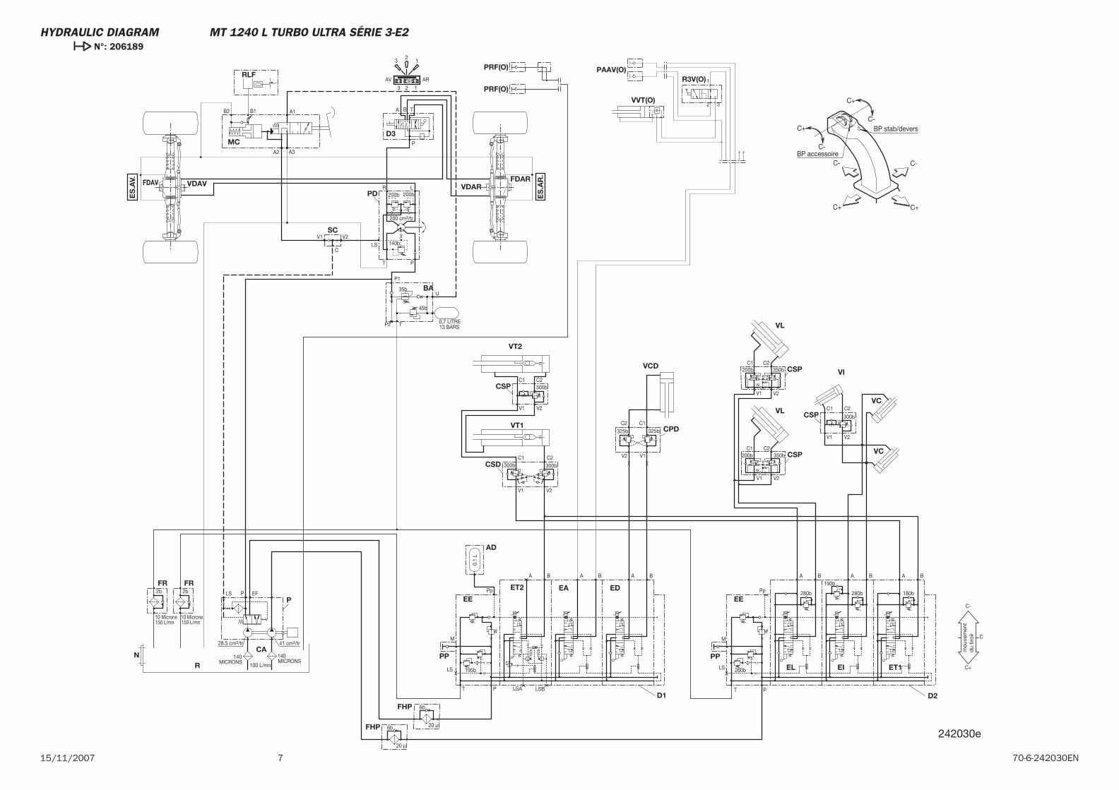
715/11/2007 70-6-242030EN
C+
C+ C+
C-
C-
C- C-
C+ BP stab/devers
BP accessoire
242030e
140MICRONS
160b
160b
6b
6b
280bX
XX
X 260b
Pp
LS
M
PT
X 195b
Pp
13 BARS0,7 LITRE
U
P1
35b
45b
TP2
20 μ
0.1
L
180b280b
190b
V1 V2
C1 C2
300b
A B
150 L/mn150 L/mn
41 cm3/tr28.5 cm3/tr
10 Microns
2b
10 Microns
2b EFLS P
MICRONS140
100 L/mn
200 cm3/tr
140b
200b
BA T
123
P
LR
PT
LS
A1
A3A2
B2 B1
V2V1
200b
ARAV
123
12
3
C
300bC2C1
V2V1
300b
300bC2C1
V2V1
B BA AA B
LS
M
PT
BA
X
LSA LSB
20 μ
BA
1
2 3
C
C-
C+
CA
EE
PP
EE
BA
FHP
AD
ET1EI
N
CSP
VC
VI
VC
EL
P
R
FR FR
D3
PD
MC
RLF
SC
VDAVFDAV VDARFDAR
VT1
VT2
CSD
CSP
EA
PP
ET2
FHPD2
ED
D1
R3V(O)
VVT(O)
PAAV(O)
PRF(O)
PRF(O)
mou
vem
ent
du
tiroi
r
CSP
VL
VL
CSP
V1 V2
C1200b
W
C2
K
350bB A
V1 V2
C1200b
W
C2
K
350bB A
CPD
VCD
325b
V1V2
325b
C1C2
ES
.AV.
ES
.AR
.
HYDRAULIC DIAGRAM MT 1240 L TURBO ULTRA SÉRIE 3-E2 N°: 206189

8 15/11/200770-6-242030EN
MT 1335 SL Série 3-E2
15 / 11 / 2007
HYDRAULIC
70-6-245198 EN

2 15/11/200770-6-245198EN

3 70-6-245198EN15/11/2007
-HYDRAULIC DIAGRAM
MT 1335 SL Série 3-E2 . . . . . . . . . . . . . . . . . . . . . . . . . . . . . . . . . . . . . . . . . . . . . . . . 4
CONTENTS
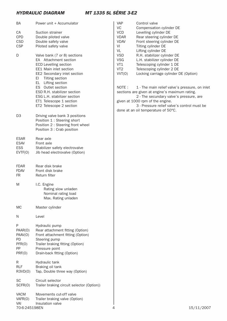
4 15/11/200770-6-245198EN
BA Power unit + Accumulator
CA Suction strainerCPD Double piloted valveCSD Double safety valveCSP Piloted safety valve
D Valve bank (7 or 8) sections EA Attachment section ECD Levelling section EE1 Main inlet section EE2 Secondary inlet section EI Tilting section EL Lifting section ES Outlet section ESD R.H. stabilizer section ESG L.H. stabilizer section ET1 Telescope 1 section ET2 Telescope 2 section
D3 Driving valve bank 3 positions Position 1 : Steering short Position 2 : Steering front wheel Position 3 : Crab position
ESAR Rear axleESAV Front axleESS Stabilizer safety electrovalveEVTF(O) Jib head electrovalve (Option)
FDAR Rear disk brakeFDAV Front disk brakeFR Return fi lter
M I.C. Engine Rating slow unladen Nominal rating load Max. Rating unladen
MC Master cylinder
N Level
P Hydraulic pump PAAR(O) Rear attachment fi tting (Option) PAAV(O) Front attachment fi tting (Option) PD Steering pumpPFR(O) Trailer braking fi tting (Option)PP Pressure pointPRF(O) Drain-back fi tting (Option)
R Hydraulic tankRLF Braking oil tankR3VD(O) Tap, Double three way (Option)
SC Circuit selectorSCFR(O) Trailer braking circuit selector (Option))
VACM Movements cut-off valve VAFR(O) Trailer braking valve (Option) VAI Insulation valve
VAP Control valveVC Compensation cylinder DEVCD Levelling cylinder DEVDAR Rear steering cylinder DEVDAV Front steering cylinder DEVI Tilting cylinder DEVL Lifting cylinder DEVSD R.H. stabilizer cylinder DEVSG L.H. stabilizer cylinder DEVT1 Telescoping cylinder 1 DEVT2 Telescoping cylinder 2 DEVVT(O) Locking carriage cylinder DE (Option)
NOTE : 1 - The main relief valve’s pressure, on inlet sections are given at engine’s maximum rating. 2 - The secundary valve’s pressure, are given at 1000 rpm of the engine. 3 - Pressure relief valve’s control must be done at an oil temperature of 50°C.
HYDRAULIC DIAGRAM MT 1335 SL SÉRIE 3-E2
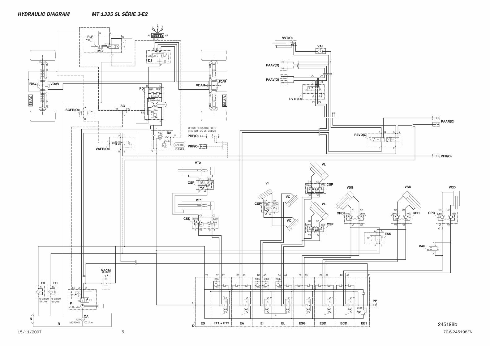
515/11/2007 70-6-245198EN
ES
.AV.
ES
.AR
.
MC
EA ECD
CSD
VT2
VT1
ESS
VSD
CPD
FDARVDARFDAV VDAV
SC
PD
D3
BA
FRFR
R
P
ESDEL ESGEID
ES
PP
EE1ET1 + ET2
CA
CPD
VSG
VC
VI
VL
CSPVC
VL
CSP
N
VAP
CPD
VCD
CSP
CSP
SCFR(O)
VAFR(O)
PFR(O)
PRF(O)
PRF(O)
VAI
VVT(O)
PAAV(O)
PAAV(O)
EVTF(O)
R3VD(O)
PAAR(O)
VACMA6B6 A5B5
300b
V1 V2
C1 C2300b
T
BA
P
C
C2 C1280b
V2 V1
100b
200b
C1
W
V1
K
350b
C2
V2
32
1
3 2 1AV AR
200b
V1 V2
LS
T P
R L
P
3 2 1
TA B
200b
140b
200 cm3/tr
P2 T
45±5b
35b
P1
U
13 BARS
0,7 LITRE
100 L/mn125
MICRONS
CFLS EF2b
10 Microns
2b
10 Microns
43.77 cm3/tr
150 L/mn 150 L/mn
A2B2A3
280b
B3
280b
A4B4A7
190b
B7T2
T1
B1 A1 P
260b
180b
C2C1280b
V2V1
100b
200bC1
W
V1
K
350bC2
V2
A
B
C2
325b
V2
C1
325b
V1
V2V1
C1 C2
V2V1
C1 C2
B
TP
N
B
A
OPTION RETOUR DE FUITEINTERIEUR OU EXTERIEUR
C1 C2
C3C4
P1 P2
E
BA BA
E
B A
B A
P
N
LB
RLF
110b
110b 315b
315b
Y
Ø1
245198b
HYDRAULIC DIAGRAM MT 1335 SL SÉRIE 3-E2

6 15/11/200770-6-245198EN
MT 1335 SL Turbo Série 3-E2MT 1340 SL Turbo Série 3-E2
15 / 11 / 2007
HYDRAULIC DIAGRAM
70-6-245184 FR

2 15/11/200770-6-245184EN
3 70-6-245184EN15/11/2007
-HYDRAULIC DIAGRAM
MT 1335 SL Turbo Série 3-E2 . . . . . . . . . . . . . . . . . . . . . . . . . . . . . . . . . . . . . . . . . . . . 4 MT 1340 SL Turbo Série 3-E2
CONTENTS
4 15/11/200770-6-245184EN
BA Power unit + Accumulator
CA Suction strainerCPD Double piloted valveCSD Double safety valveCSP Piloted safety valve
D Valve bank (7 or 8) sections EA Attachment section ECD Levelling section EE1 Main inlet section EE2 Secondary inlet section EI Tilting section EL Lifting section ES Outlet section ESD R.H. stabilizer section ESG L.H. stabilizer section ET1 Telescope 1 section ET2 Telescope 2 section
D3 Driving valve bank 3 positions Position 1 : Steering short Position 2 : Steering front wheel Position 3 : Crab position
ESAR Rear axleESAV Front axleESS Stabilizer safety electrovalveEVTF(O) Jib head electrovalve (Option)
FDAR Rear disk brakeFDAV Front disk brakeFR Return fi lter
M I.C. Engine Rating slow unladen Nominal rating load Max. Rating unladen
MC Master cylinder
N Level
P Hydraulic pumpPAAR(O) Rear attachment fi tting (Option)PAAV(O) Front attachment fi tting (Option) PD Steering pumpPFR(O) Trailer braking fi tting (Option)PP Pressure pointPRF(O) Drain-back fi tting (Option)
R Hydraulic tankRLF Braking oil tankR3VD(O) Tap, Double three way (Option)
SC Circuit selectorSCFR(O) Trailer braking circuit selector (Option)
VACM Movements cut-off valveVAFR(O) Trailer braking valve (Option)VAI Insulation valve
VAP Control valveVC Compensation cylinder DEVCD Levelling cylinder DEVDAR Rear steering cylinder DEVDAV Front steering cylinder DEVI Tilting cylinder DEVL Lifting cylinder DEVSD R.H. stabilizer cylinder DEVSG L.H. stabilizer cylinder DEVT1 Telescoping cylinder 1 DEVT2 Telescoping cylinder 2 DEVVT(O) Locking carriage cylinder DE (Option)
NOTE : 1 - The main relief valve’s pressure, on inlet sections are given at engine’s maximum rating.
2 - The secundary valve’s pressure, are given at 1000 rpm of the engine.
3 - Pressure relief valve’s control must be done at an oil temperature of 50°C.
HYDRAULIC DIAGRAM MT 1335 SL TURBO SÉRIE 3-E2 MT 1340 SL TURBO SÉRIE 3-E2
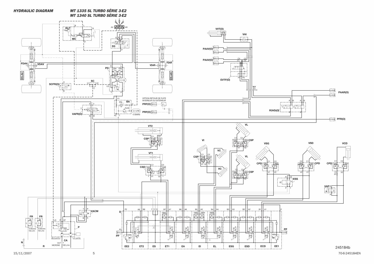
515/11/2007 70-6-245184EN
MC
EA ECD
CSD
VT2
VT1
ESS
VSD
CPD
FDARVDAR
FDAV VDAV
SC
PD
D3
BA
FRFR
R
P
ESDEL ESGEI
D
ESET2EE2
PP
PP
EE1ET1
CA
CPD
VSG
VC
VI
VL
CSPVC
VL
CSP
N
VAP
CPD
VCD
CSP
CSP
SCFR(O)
VAFR(O)
PFR(O)
PRF(O)
PRF(O)
VAI
VVT(O)
PAAV(O)
PAAV(O)
EVTF(O)
R3VD(O)
PAAR(O)
VACMA6B6 A5B5
300b
V1 V2
C1 C2300b
T
BA
P
C
C2 C1280b
V2 V1
100b
200bC1
W
V1
K
350bC2
V2
32
1
3 2 1AV AR
200b
V1 V2
LS
T P
R L
P
3 2 1
TA B
200b
140b
200 cm3 /tr
P2 T
45±5b
35b
P1
U
13 BARS
0,7 LITRE
100 L/mn125
MICRONS
PLS EF2b
10 Microns
2b
10 Microns
28.5 cm3/tr 41 cm3/tr
150 L/mn 150 L/mn
B8 A2B2A3
280b
B3
280b
A4B4A7
190b
B7T2T T1A8P2
160b
P3
B1 A1 P
260b
180b
C2C1280b
V2V1
100b
200bC1
W
V1
K
350bC2
V2
A
B
C2325b
V2
C1325b
V1
V2V1
C1 C2
V2V1
C1 C2
B
TP
N
B
A
OPTION RETOUR DE FUITEINTERIEUR OU EXTERIEUR
C1 C2C3C4
P1 P2
E
BA BA
E
P
AB
T
B A
B A
P
N
LB
RLF
110b
110b 315b
315b
Y
ES
.AV.
ES
.AR
.
245184b
Ø1
HYDRAULIC DIAGRAM MT 1335 SL TURBO SÉRIE 3-E2 MT 1340 SL TURBO SÉRIE 3-E2

6 15/11/200770-6-245184EN

MT 1340 SL Turbo Ultra Série 3-E2
15 / 11 / 2007
HYDRAULIC DIAGRAM
70-6-245212 EN

2 15/11/200770-6-245212EN
3 70-6-245212EN15/11/2007
-HYDRAULIC DIAGRAM
MT 1340 SL Turbo Ultra Série 3-E2 Légende . . . . . . . . . . . . . . . . . 4
MT 1340 SL Turbo Ultra Série 3-E2 N°: 206188. . . . . . . . . . . 5
MT 1340 SL Turbo Ultra Série 3-E2 N°: 206189 . . . . . . . . . . . 7
CONTENTS
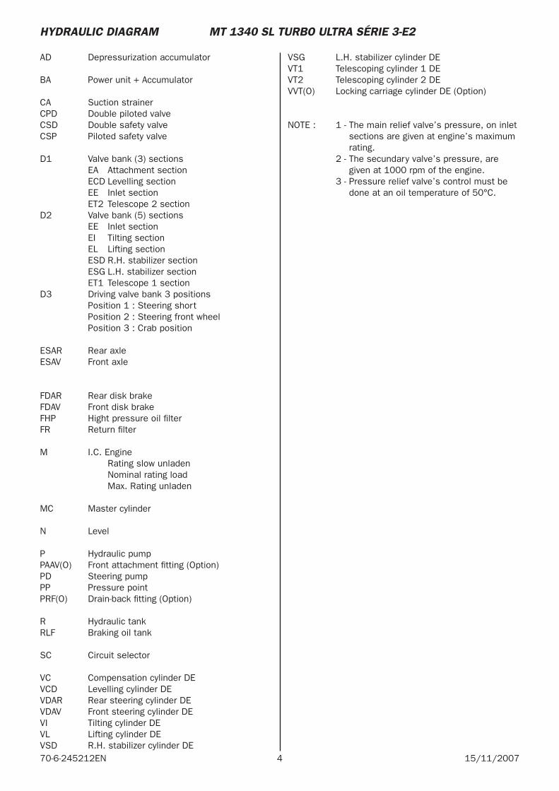
4 15/11/200770-6-245212EN
AD Depressurization accumulator
BA Power unit + Accumulator
CA Suction strainerCPD Double piloted valveCSD Double safety valveCSP Piloted safety valve
D1 Valve bank (3) sections EA Attachment section ECD Levelling section EE Inlet section ET2 Telescope 2 sectionD2 Valve bank (5) sections EE Inlet section EI Tilting section EL Lifting section ESD R.H. stabilizer section ESG L.H. stabilizer section ET1 Telescope 1 sectionD3 Driving valve bank 3 positions Position 1 : Steering short Position 2 : Steering front wheel Position 3 : Crab position
ESAR Rear axleESAV Front axle
FDAR Rear disk brakeFDAV Front disk brakeFHP Hight pressure oil fi lterFR Return fi lter
M I.C. Engine Rating slow unladen Nominal rating load Max. Rating unladen
MC Master cylinder
N Level
P Hydraulic pump PAAV(O) Front attachment fi tting (Option) PD Steering pump PP Pressure point PRF(O) Drain-back fi tting (Option)
R Hydraulic tankRLF Braking oil tank
SC Circuit selector
VC Compensation cylinder DE VCD Levelling cylinder DEVDAR Rear steering cylinder DEVDAV Front steering cylinder DEVI Tilting cylinder DEVL Lifting cylinder DEVSD R.H. stabilizer cylinder DE
VSG L.H. stabilizer cylinder DEVT1 Telescoping cylinder 1 DEVT2 Telescoping cylinder 2 DEVVT(O) Locking carriage cylinder DE (Option)
NOTE : 1 - The main relief valve’s pressure, on inlet sections are given at engine’s maximum rating.
2 - The secundary valve’s pressure, are given at 1000 rpm of the engine.
3 - Pressure relief valve’s control must be done at an oil temperature of 50°C.
HYDRAULIC DIAGRAM MT 1340 SL TURBO ULTRA SÉRIE 3-E2
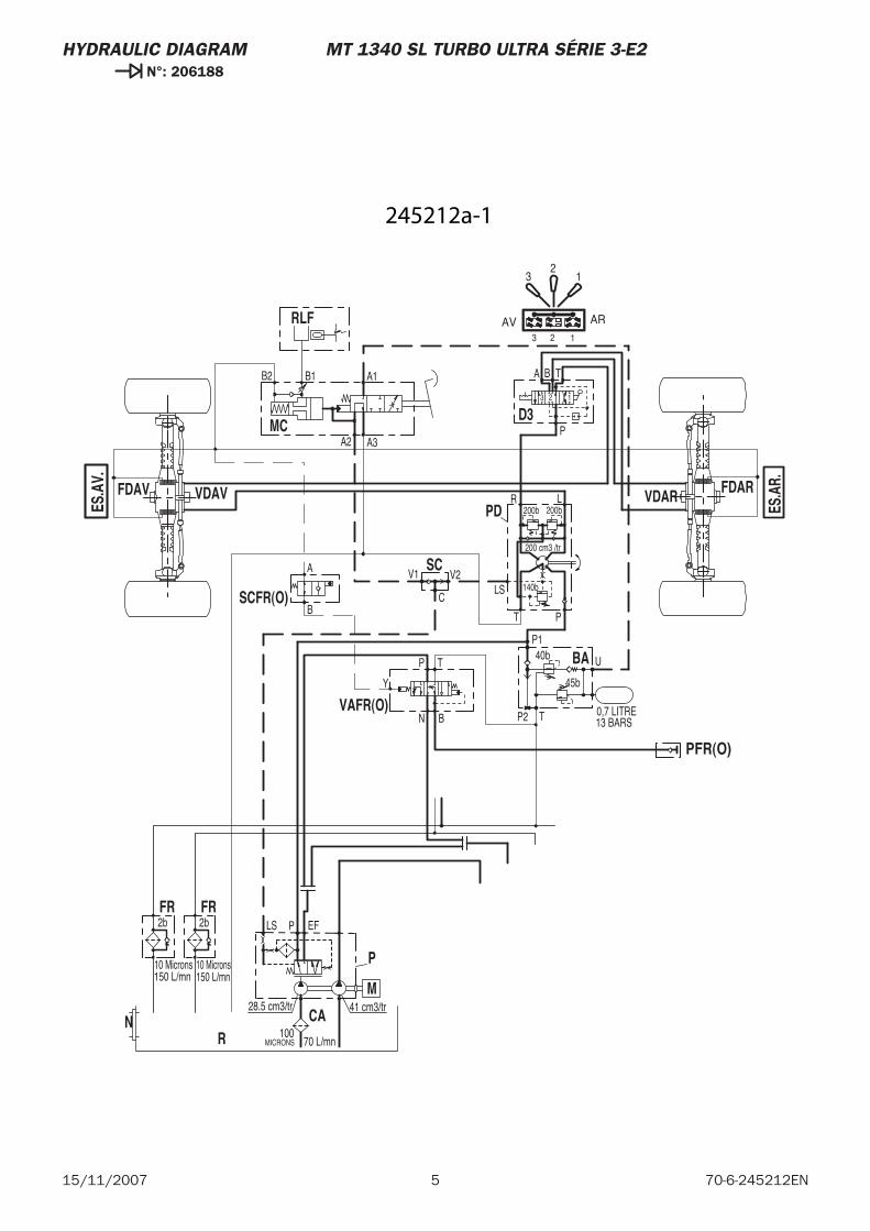
5 70-6-245212EN15/11/2007
HYDRAULIC DIAGRAM MT 1340 SL TURBO ULTRA SÉRIE 3-E2 N°: 206188
13 BARS0,7 LITRE
U
P140b
45b
TP2
150 L/mn150 L/mn
41 cm3/tr28.5 cm3/tr
10 Microns
2b
10 Microns
2b EFLS P
MICRONS100
70 L/mn
200 cm3 /tr
140b
200b
BA T
123
P
LR
PT
LS
A1
A3A2
B2 B1
V2V1
200b
C
A
B
N
P T
B
BA
N CA
P
R
FR FR
M
D3
PD
MC
RLF
SC
VDAVFDAV VDAR FDAR
PFR(O)
VAFR(O)
SCFR(O)
Y
ES.A
V.
ES.A
R.
32
1
3 2 1
ARAV
245212a-1
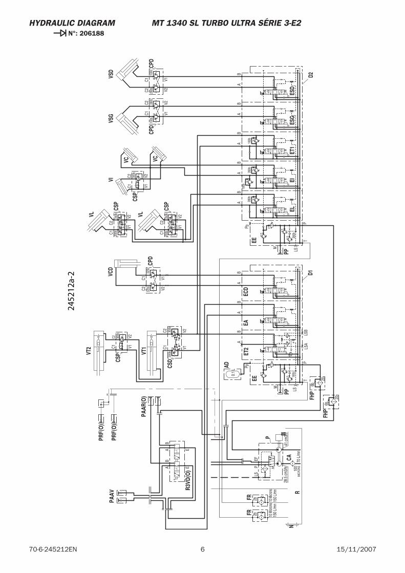
6 15/11/200770-6-245212EN
HYDRAULIC DIAGRAM MT 1340 SL TURBO ULTRA SÉRIE 3-E2 N°: 206188
6b
6b
280b
X
X
X
X26
0b
Pp
LS
M
PT
X19
5b
Pp
20
0.1
L
180b
280b
190b
V2
C235
0bK
V1W
V1V2
C120
0b
100b
V1V228
0b
C1C2 30
0b
C1C2
AB
150 L
/mn
150
L/m
n
41 cm
3/tr
28.5
cm3/
tr
10 M
icron
s
2b
10 M
icron
s
2bEF
LSP
MIC
RONS100
70 L
/mn
AB
V2
C235
0bK
V1W
C1 200b
AB
100b
V1V2280b
C1C2
300b
C2C1
V2V1
300b
300b
C2C1
V2V1
BB
BB
AA
AA
AB
LS
M
PT
BA
X
LSA
LSB
20
BA
325b
V1V232
5bC1
C2
EAB
AB
E
EE
PP
EE
PAAV
FHP
AD
ESD
ESG
ET1
EIN
CSP
CSP
VL
VC
CSP
VL
VI
VC
VSG
CPD
CAEL
P
R
FRFR
M
CPD
VSD
VT1
VT2
CSDCS
P
EA
PP
ET2
FHP
D2
ECD
D1
CPD
VCD
PAAR
(O)
R3VD
(O)
PRF(
O)
PRF(
O)
2452
12a-
2
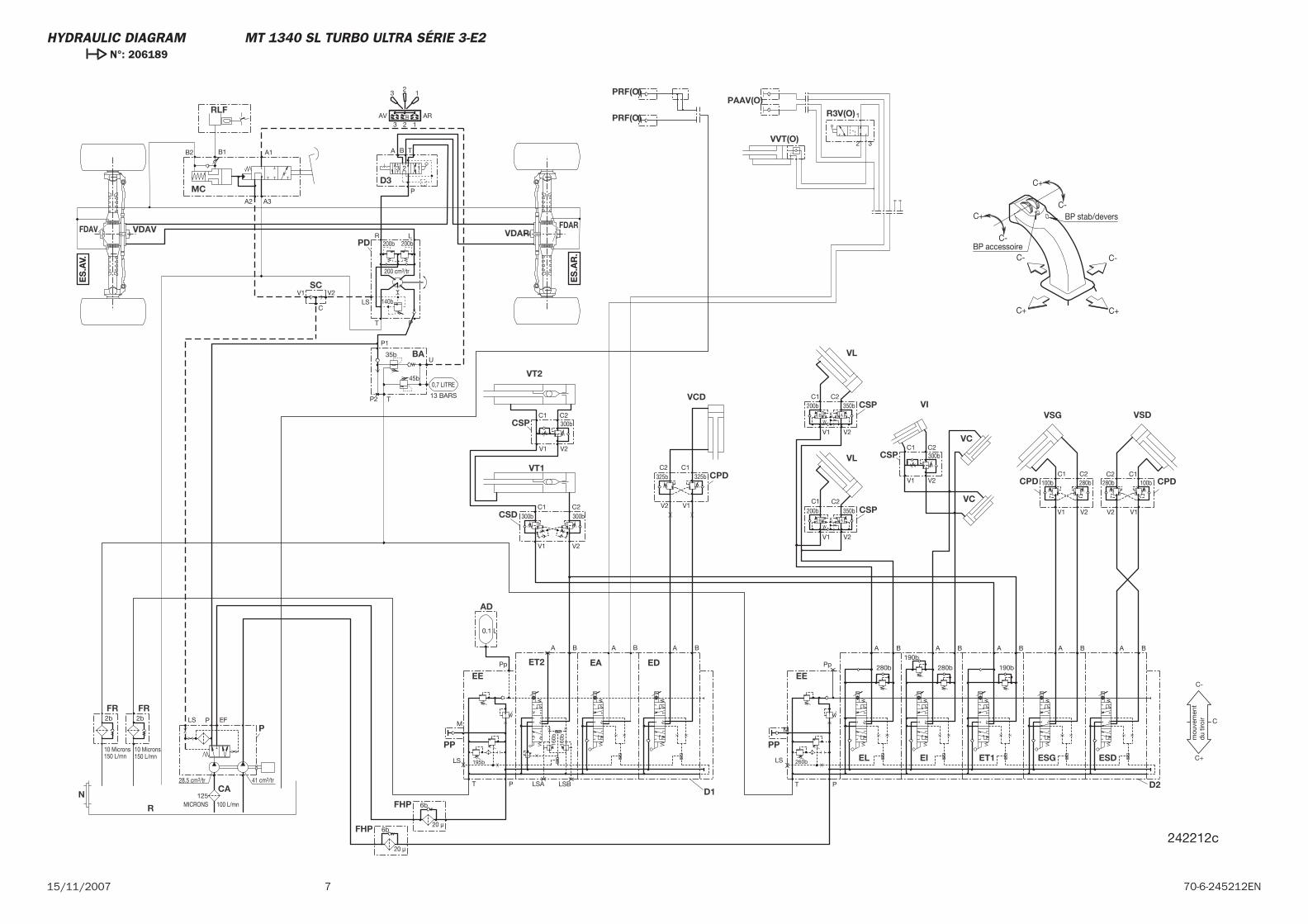
715/11/2007 70-6-245212EN
C+
C+ C+
C-
C-
C- C-
C+ BP stab/devers
BP accessoire
mou
vem
ent
du
tiroi
r
ES
.AV.
ES
.AR
.
160b
160b
6b
6b
280bX
XXX
260b
Pp
LS
M
PT
X 195b
Pp
13 BARS
0,7 LITRE
U
P1
35b
45b
TP2
0.1 L
190b280b
190b
V2
C2350b
K
V1
W
V1 V2
C1200b
100b
V1 V2
280b
C1 C2300b
C1 C2
A B
150 L/mn150 L/mn
41 cm3/tr28.5 cm3/tr
10 Microns
2b
10 Microns
2b EFLS P
MICRONS125
100 L/mn
200 cm3/tr
140b
200b
BA T
123
P
LR
PT
LS
A1
A3A2
B2 B1
V2V1
200b
ARAV123
12
3
AB
V2
C2350b
K
V1
W
C1200b
AB
100b
V1V2
280bC1C2
C
300bC2C1
V2V1
300b
300bC2C1
V2V1
B B B BA A A AA B
LS
M
PT
BA
X
LSA LSB
BA
325b
V1V2
325bC1C2
1
2 3
C+
C-
C
EE
PP
EE
BA
FHP
AD
ESDESGET1EI
N
CSP
CSP
VL
VCCSP
VL
VI
VC
VSG
CPD
CA
EL
P
R
FR FR
D3
PD
MC
RLF
SC
VDAVFDAV VDARFDAR
CPD
VSD
VT1
VT2
CSD
CSP
EA
PP
ET2
FHP
D2
ED
D1
CPD
VCD
PRF(O)
PRF(O)PAAV(O)
VVT(O)
R3V(O)
20 μ
20 μ
242212c
HYDRAULIC DIAGRAM MT 1340 SL TURBO ULTRA SÉRIE 3-E2 N°: 206189

8 15/11/200770-6-245212EN
MT 1340 SL Turbo Mono Ultra ORH Série 3-E2
15 / 11 / 2007
HYDRAULIC DIAGRAM
70-6-245185 EN

2 15/11/200770-6-245185EN

3 70-6-245185EN15/11/2007
-HYDRAULIC DIAGRAM
MT 1340 SL Turbo Mono Ultra ORH Série 3-E2 Légende . . . . . . . . . . . . . . . . . 4
MT 1340 SL Turbo Mono Ultra ORH Série 3-E2 N°: 204232. . . . . . . . . . . 5
MT 1340 SL Turbo Mono Ultra ORH Série 3-E2 N°: 204233 . . . . . . . . . . . 9
CONTENTS
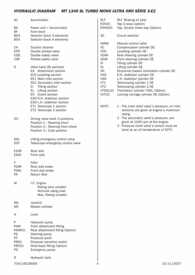
4 15/11/200770-6-245185EN
AC Accumulator
BA Power unit + AccumulatorBF Fore block BS3 Selector block 3 elementsBS4 Selector block 4 elements
CA Suction strainer CPD Double piloted valveCSD Double safety valveCSP Piloted safety valve
D Valve bank (8) sections EA Attachment section ECD Levelling section EE1 Main inlet section EE2 Secondary inlet section EI Tilting section EL Lifting section ES Outlet section ESD R.H. stabilizer section ESG L.H. stabilizer section ET1 Telescope 1 section ET2 Telescope 2 section
D3 Driving valve bank 3 positions Position 1 : Steering short Position 2 : Steering front wheel Position 3 : Crab position
DSL Lifting emergency control valveDST Telescope emergency control valve
ESAR Rear axleESAV Front axle
F Filter FDAR Rear disk brakeFDAV Front disk brakeFR Return fi lter
M I.C. Engine Rating slow unladen Nominal rating load Max. Rating unladen
MA JoystickMC Master cylinder
N Level
P Hydraulic pumpPAAV Front attachment fi tting PAAR(O) Rear attachment fi tting (Option) PD Steering pumpPP Pressure pointPRES Pressure sensitive switchPRF(O) Drain-back fi tting (Option)PS Emergency pump
R Hydraulic tank
RLF RLF Braking oil tank R3V(O) Tap 3 ways (option)R3VD(O) Tap, Double three way (Option)
SC Circuit selector
VARM Manual control valveVC Compensation cylinder DEVCD Levelling cylinder DEVDAR Rear steering cylinder DEVDAV Front steering cylinder DEVI Tilting cylinder DEVL Lifting cylinder DEVN Personnel basket orientation cylinder DEVSD R.H. stabilizer cylinder DEVSG L.H. stabilizer cylinder DEVT1 Telescoping cylinder 1 DEVT2 Telescoping cylinder 2 DEVTSDL(O) Translation cylinder TSDL (Option)VVT(O) Locking carriage cylinder DE (Option)
NOTE : 1 - The main relief valve’s pressure, on inlet sections are given at engine’s maximum rating.
2 - The secundary valve’s pressure, are given at 1000 rpm of the engine.
3 - Pressure relief valve’s control must be done at an oil temperature of 50°C.
HYDRAULIC DIAGRAM MT 1340 SL TURBO MONO ULTRA ORH SÉRIE 3-E2
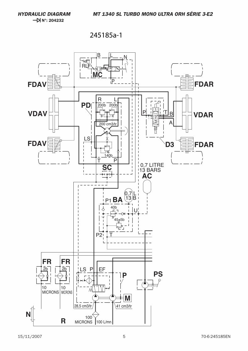
5 70-6-245185EN15/11/2007
HYDRAULIC DIAGRAM MT 1340 SL TURBO MONO ULTRA ORH SÉRIE 3-E2 N°: 204232
0,7 LITRE13 BARS
32
1
41 cm3/tr28,5 cm3/tr
MICRONS10
2b
MICRONS10
2b EFLS P
T
LS
P
R L
P T
A
B
P2 T
45±5b
40b
P1
U
0,7 L13 B
200b 200b
200 cm3/tr
140b
MICRONS100
100 L/mn
AC
P
R
FR FR
M
FDAV
SC
VDAVPD
FDAV
D3 FDAR
VDAR
FDAR
PS
BA
MCRLF
B L N
P
N
245185a-1
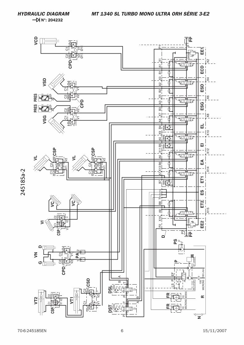
6 15/11/200770-6-245185EN
HYDRAULIC DIAGRAM MT 1340 SL TURBO MONO ULTRA ORH SÉRIE 3-E2 N°: 204232
C2C1
V1V2
C2C1 V1
V2
Ø1
Ø1
41 c
m3/
tr28
,5 c
m3/
tr
MIC
RO
NS
102b
MICR
ONS
102bE
FLS
P
P3
160b
P2
A8
T1
TT
2B
618
0b
A6
B5
190b
A5
B4
A4
280b
300b
V1
V2
C1
C2
300b
B3
280b
A3
B2
A2
260b
P
P1
V2
V1
W
K
100b
V1
V2
280b
V2
280b
C2
350b
200bC1
C1
C2
C2
V1
100b
C1
V2
325bC2
V1
325b
C1
A1
B1
B7
A7
X1
X3
X5
X7
X9
X11
X13
X16
X14
X15
X12
X10
X8
X6
X4
X2
V2
350bC2
V1
C1
350b
PT
BA
PTB
A
B8
T3
12
MIC
RO
NS
100
100
L/m
n
C
V1
V2
C1
200b
W
C2 CK
350b
45b
45b
200b
200b
CSP
CSP
PRES
A32 1
PRES
A32 1
P
R
FR
FR
M
PP
EE
2E
T2
ES
D
EA
ET
1E
I
CS
D
VT
1
VT
2
PA
ES
GE
LE
SD
EE
1
PP
CS
P
VL
VC
VL
VI
VC
VS
G
CP
D
VS
D
VC
D
CP
D
EC
D
CP
D
VN
PS
DS
TD
SL
GD
CS
P
315b
315b
110b
110b
N
2451
85a-
2
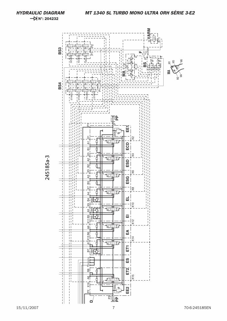
7 70-6-245185EN15/11/2007
HYDRAULIC DIAGRAM MT 1340 SL TURBO MONO ULTRA ORH SÉRIE 3-E2 N°: 204232
M3
M4
M6
M1
M2
P3
160b
P2
A8
T1
TT
2B
618
0b
A6
B5
190b
A5
B4
A4
280b
B3
280b
A3
B2
A2
260b
P
P1
A1
B1
B7
A7
X1
X3
X5
X7
X9
X11
X13
X16
X14
X15
X12
X10
X8
X6
X4
X2
B8
T3
43
21
PT
P
T
S1
E1
S2
E2
S3
E3
S4
E4
TP
2P
1
P1
P2
T
132
ST
AB
. D
ST
AB
. G
TE
LES
C. 1
LEV
AG
E
DE
VE
RS
AC
CE
SS
.
INC
LIN
. MIC
RONS
10
PP
EE
2E
T2
ES
D
EA
ET
1E
IE
SG
EL
ES
DE
E1
PP
EC
DM
A
BS
4B
S3
VA
RM
BS
F
MA
2451
85a-
3

8 15/11/200770-6-245185EN
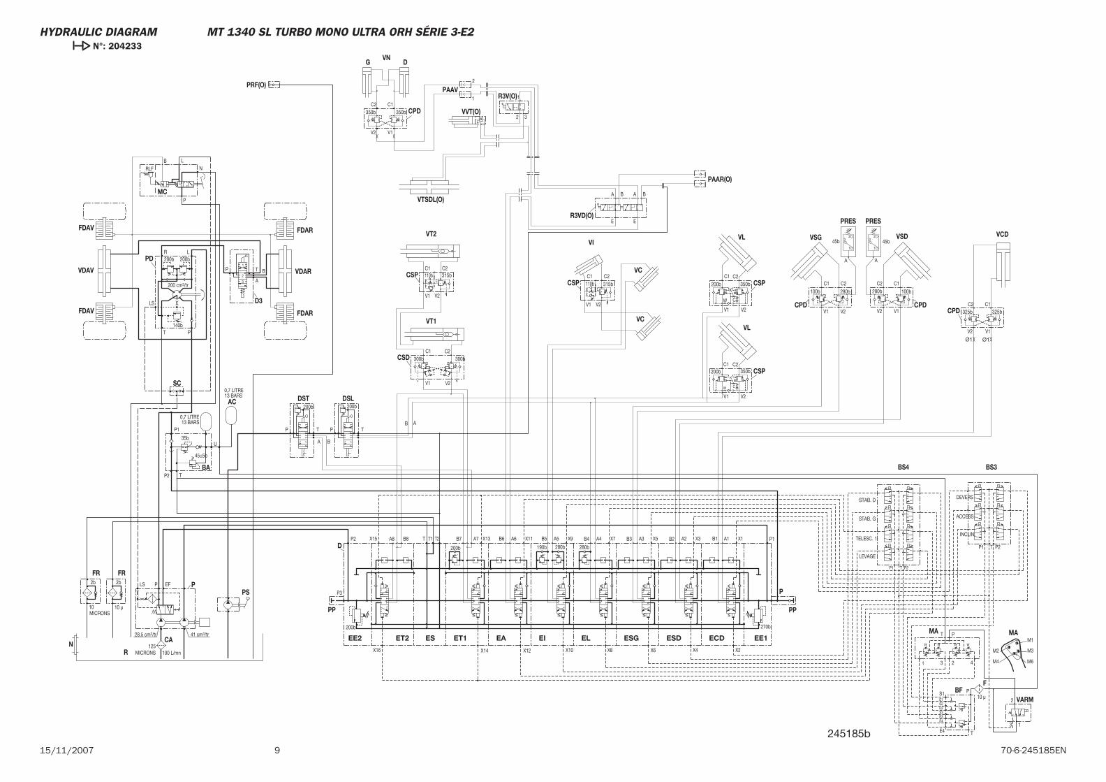
915/11/2007 70-6-245185EN
PAAV
MC
CSP
FBF
VARM
BS3BS4
MA
BA
DSLDST
PS
CPD
VCDVSD
CPD CPD
VSG
VC
VIVL
VCVL
CSP
VT2FDAR
VT1
CSD
VDAR
FDAR
D3
FDAV
PD
VDAV
SC
FDAV
FRFR
R
P
PRES PRES
AC
CSPCSP
VVT(O)CPD
VNG D
P
D 280b280b190b
T2T T1P2
200b
P3
P1
270b
200b
PRF(O)
PAAR(O)
R3VD(O)
VTSDL(O)
R3V(O)
CAN
1
23
A
1
23
A
V2V1
C1 C2
V2V1
C1 C2
V2 V1
A7B8 B7 A2B2A3B3A4B4A5B5A6B6A8 B1 A1
E
A BA B
E
32
11
2
200b200b
45b45b
350bK
C
C2
W
200bC1
V2V1
C
100 L/mn125
MICRONS
140b
200 cm3/tr
200b200b
10 μ
INCLIN.
ACCESS.
DEVERS
LEVAGE
TELESC. 1
STAB. G
STAB. D
2
3 1
T P2P1
P1 P2T
E4
S4E3S3E2S2E1S1
T
P
T P
1 23 4
13 BARS0,7 LITRE
U
P1
35b
45±5b
TP2
ABTP
A B
TP
C1325b
V1
C2325b
V2
C1
100b
V1
C2C2C1C1
200b 350bC2
280b
V2
280b
V2V1
100bK
W
V1 V2
300bC2C1
V2V1
B
A
TP
300b
LR
P
LS
T
PLS EF2b
10 μ
2b
10MICRONS
28,5 cm3/tr 41 cm3/tr
1
2
3
13 BARS0,7 LITRE
350bC2 C1
350b
P
NLB
RLF
110b
110b
315b
315b
ESDEL ESGEIEAESET2EE2
PP
ECD
PP
EE1ET1
X4X6X8X10X12X16
X15 X13 X11 X9 X7 X5
X2
X3 X1
X14
MA
M2
M1
M6M4
M3
Ø1 Ø1
245185b
HYDRAULIC DIAGRAM MT 1340 SL TURBO MONO ULTRA ORH SÉRIE 3-E2 N°: 204233

10 15/11/200770-6-245185EN
MT 1340 SL Turbo Ultra ORH RC Série 3-E2
15 / 11 / 2007
HYDRAULIC DIAGRAM
70-6-242031 EN

2 15/11/200770-6-242031EN

3 70-6-242031EN15/11/2007
-HYDRAULIC DIAGRAM
MT 1340 SL Turbo Ultra ORH RC Série 3-E2 Légende . . . . . . . . . . . . . . . . . 4
MT 1340 SL Turbo Ultra ORH RC Série 3-E2 N°: 206188. . . . . . . . . . . 5
MT 1340 SL Turbo Ultra ORH RC Série 3-E2 N°: 206189 . . . . . . . . . . . 7
CONTENTS
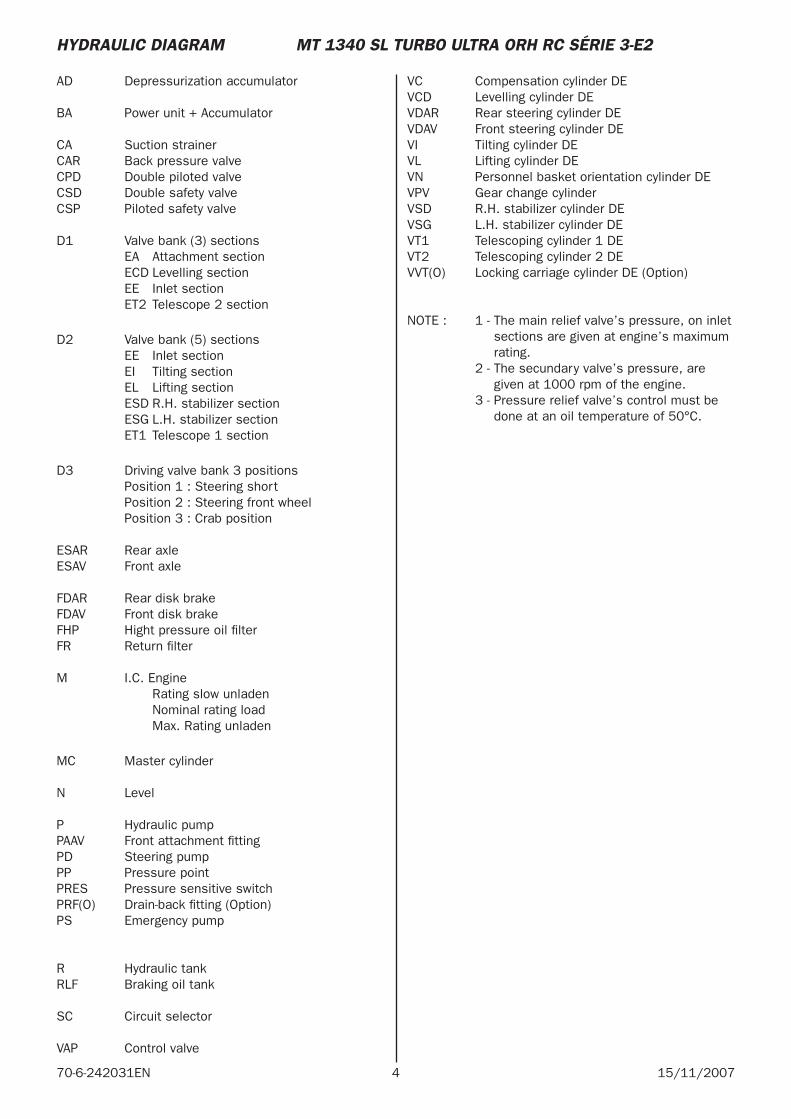
4 15/11/200770-6-242031EN
AD Depressurization accumulator
BA Power unit + Accumulator
CA Suction strainerCAR Back pressure valveCPD Double piloted valveCSD Double safety valveCSP Piloted safety valve
D1 Valve bank (3) sections EA Attachment section ECD Levelling section EE Inlet section ET2 Telescope 2 section
D2 Valve bank (5) sections EE Inlet section EI Tilting section EL Lifting section ESD R.H. stabilizer section ESG L.H. stabilizer section ET1 Telescope 1 section
D3 Driving valve bank 3 positions Position 1 : Steering short Position 2 : Steering front wheel Position 3 : Crab position
ESAR Rear axleESAV Front axle
FDAR Rear disk brakeFDAV Front disk brakeFHP Hight pressure oil fi lterFR Return fi lter
M I.C. Engine Rating slow unladen Nominal rating load Max. Rating unladen
MC Master cylinder
N Level
P Hydraulic pumpPAAV Front attachment fi ttingPD Steering pumpPP Pressure pointPRES Pressure sensitive switchPRF(O) Drain-back fi tting (Option)PS Emergency pump
R Hydraulic tankRLF Braking oil tank
SC Circuit selector
VAP Control valve
VC Compensation cylinder DEVCD Levelling cylinder DEVDAR Rear steering cylinder DEVDAV Front steering cylinder DEVI Tilting cylinder DEVL Lifting cylinder DEVN Personnel basket orientation cylinder DEVPV Gear change cylinder VSD R.H. stabilizer cylinder DEVSG L.H. stabilizer cylinder DEVT1 Telescoping cylinder 1 DEVT2 Telescoping cylinder 2 DEVVT(O) Locking carriage cylinder DE (Option)
NOTE : 1 - The main relief valve’s pressure, on inlet sections are given at engine’s maximum rating.
2 - The secundary valve’s pressure, are given at 1000 rpm of the engine.
3 - Pressure relief valve’s control must be done at an oil temperature of 50°C.
HYDRAULIC DIAGRAM MT 1340 SL TURBO ULTRA ORH RC SÉRIE 3-E2
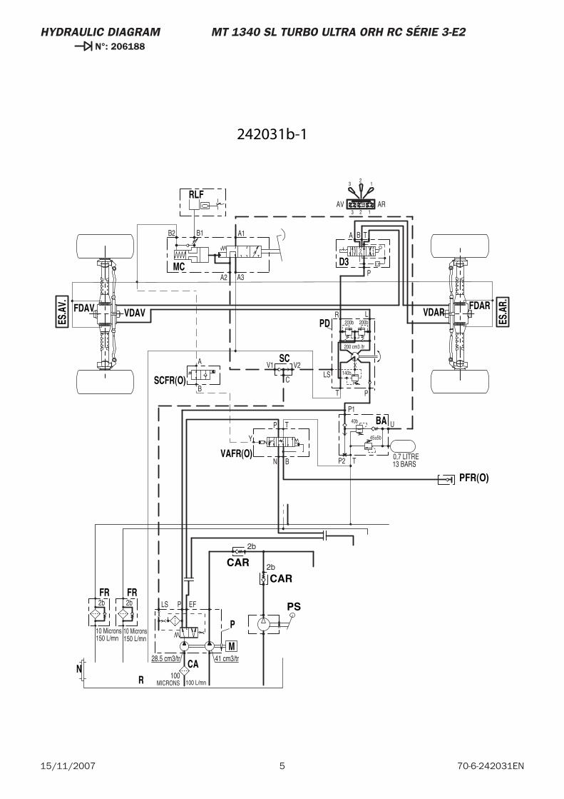
5 70-6-242031EN15/11/2007
HYDRAULIC DIAGRAM MT 1340 SL TURBO ULTRA ORH RC SÉRIE 3-E2 N°: 206188
45±5b
13 BARS0,7 LITRE
U
P140b
TP2
150 L/mn150 L/mn
41 cm3/tr28.5 cm3/tr
10 Microns
2b
10 Microns
2b EFLS P
MICRONS100
100 L/mn
200 cm3 /tr
140b
200b
BA T
123
P
LR
PT
LS
A1
A3A2
B2 B1
V2V1
200b
ARAV123
12
3
C
A
B
N
P T
B
PS
CAR
BA
N CA
P
R
FR FR
M
D3
PD
MC
RLF
SC
VDAVFDAV
ES.A
V.
VDAR
ES.A
R.FDAR
CAR
PFR(O)
VAFR(O)
SCFR(O)
2b
2b
Y
242031b-1
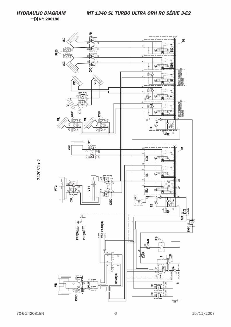
6 15/11/200770-6-242031EN
HYDRAULIC DIAGRAM MT 1340 SL TURBO ULTRA ORH RC SÉRIE 3-E2 N°: 206188
315b
110b
C2C1 V1
V2
Ø1
Ø1
C2C1 V1
V2
AB
BA
190b
280b
TP
M
LS
Pp
260b
X
X
280b
TP
AB
LSB
LSAX
AB
M LS
BA
0.1
L
Pp
195b
X
X
X
180b
100b
V1V228
0bC1
C2
150
L/m
n15
0 L/
mn
41 cm
3/tr
28.5
cm3/
tr
10 M
icron
s
2b
10 M
icron
s
2bEF
LSP
MIC
RONS10
010
0 L/
mn
100b
V1V2280b
C1C2
BB
BA
AA
325b
V1V2325b
C1C2
45b
45b
A
32 1
A
32 1
V1
V2
C1
200b
W
C2 C
K35
0b
BA
V1
V2
C1
200b
W
C2
K35
0b
BA
EAB
AB
E
6b
6b
20
20
VC
VC
VI
CS
P
CS
DCSP
VT
1
VT
2
CP
D
VN
PS
CA
R
ELEI
PP
EEEC
DET
2
PP
EA
AD
EE
PAAV
FHP
ESD
ESG
ET1
N
VSG
CPD
CA
P
R
FRFR
M
CPD
VSD
FHP
D2D1
CPD
VCD
PRES
CA
R
CIRC
UIT
DE S
ECO
URS
MO
UVEM
ENT
MEC
ANIQ
UEAU
TORI
SE
CS
P
VL
VL
CS
P
CIRC
UIT
DE S
ECO
URS
MO
UVEM
ENT
MEC
ANIQ
UEAU
TORI
SE
PAAR
(O)
R3VD
(O)
PRF(
O)
PRF(
O)
300b
V1
V2
C1
C2
300b
V2
350bC2
V1
C1
350b
12
2b
2b
C
315b
110b
2420
31b
-2
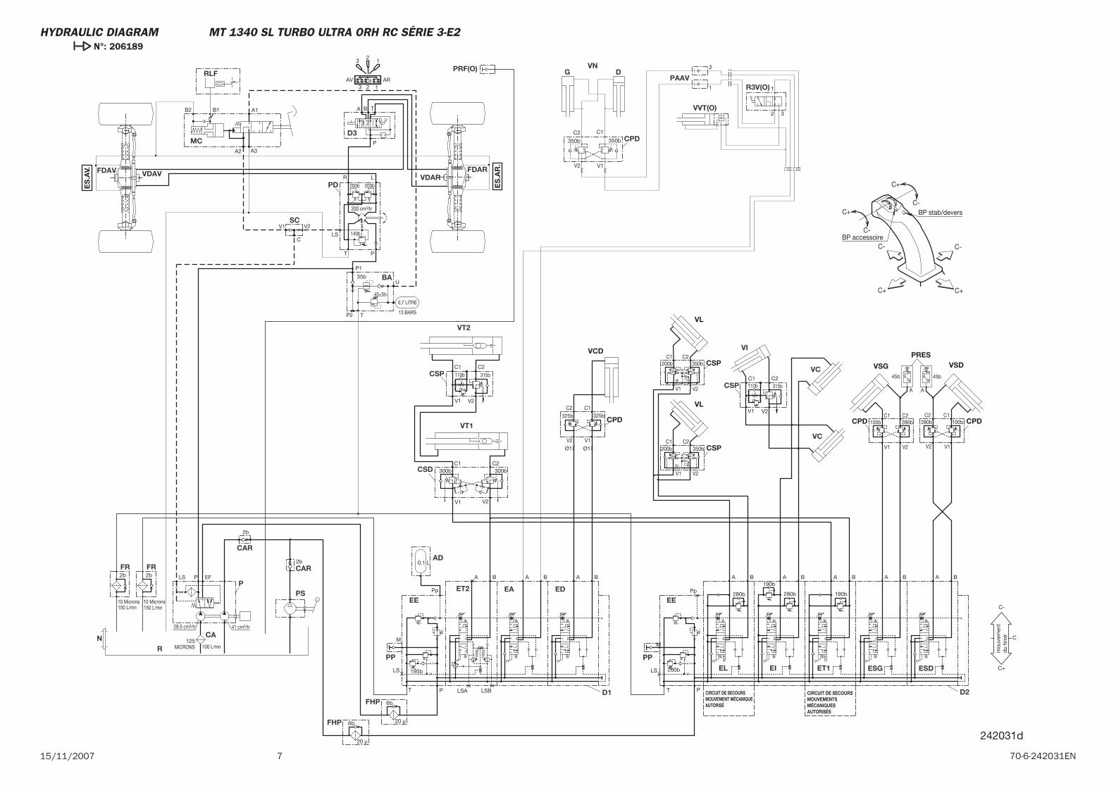
715/11/2007 70-6-242031EN
C+
C+ C+
C-
C-
C- C-
C+ BP stab/devers
BP accessoire
242031d
mou
vem
ent
du
tiroi
r
PAAV
CAR
D1 D2FHP
FDARVDAR
FDAV VDAV
SC
RLF
MC
PD
D3
FRFR
R
P
CAN
ET1 ESG ESD
FHP
BA
EE
AD
EA
PP
ET2 ED
EE
PPEIEL
CAR
PS
VT2
VT1
CSP
CSD
CSP
VI
VC
VC
CPD
VNG D
R3V(O)
VVT(O)
PRF(O)
AAA BBB
C
32
1
3 2 1AV AR
200b
V1 V2
B1B2
A2 A3
A1
LS
T P
R L
P
3 2 1
TA B
200b
140b
200 cm3/tr
100 L/mn125
MICRONS
PLS EF2b
10 Microns
2b
10 Microns
28.5 cm3/tr 41 cm3/tr
150 L/mn 150 L/mn
190b
P2 T
35b
P1
U
0,7 LITRE
13 BARS
XX
X 195b
Pp
0.1 L
A B
LS
M
BA
X
LSA LSB
BA
PT
280bX
X260b
Pp
LS
M
PT
280b
190bA B BA
V2V1
C1 C2
Ø1 Ø1
45±5b
V2V1
C1 C2110b 315b
160b
160b
V2 V1
1
2 3
1
2
C+
C-
C
20 μ
20 μ
6b
6b
2b
2b
300bC2C1
V2V1
300b
350b
C2 C1
350b
110b 315b
ES
.AV.
ES
.AR
.
CIRCUIT DE SECOURS MOUVEMENT MÉCANIQUE AUTORISÉ
CIRCUIT DE SECOURS MOUVEMENTSMÉCANIQUESAUTORISÉS
VSG
CPD CPD
VSDPRES
100b
V1 V2
280bC1 C2
100b
V1V2
280bC1C2
45b45b
A
3 2
1
A
3 2
1
CSP
VL
VL
CSP
V1 V2
C1200b
W
C2
C
K
350bB A
V1 V2
C1200b
W
C2
K
350bB A
C
CPD
VCD
325b
V1V2
325bC1C2
HYDRAULIC DIAGRAM MT 1340 SL TURBO ULTRA ORH RC SÉRIE 3-E2 N°: 206189

8 15/11/200770-6-242031EN
HYDRAULIC DIAGRAM
70-6-255787 EN
20 / 12 / 2006
MT 1435 SL Série 3-E2MT 1435 SL Turbo Série 3-E2MT 1440 SL Série 3-E2MT 1440 SL Turbo Série 3-E2MT 1440 SL Turbo ULTRA Série 3-E2MT 1440 SL Turbo MONO-ULTRA NACELLE ORH Série 3-E2MT 1440 SL Turbo ULTRA NACELLE ORH RC Série 3-E2

3
CONTENTS
– HYDRAULIC DIAGRAM
MT 1435 SL Série 3-E2 . . . . . . . . . . . . . . . . . . . . . . . . . . . . . . . . . . . 4
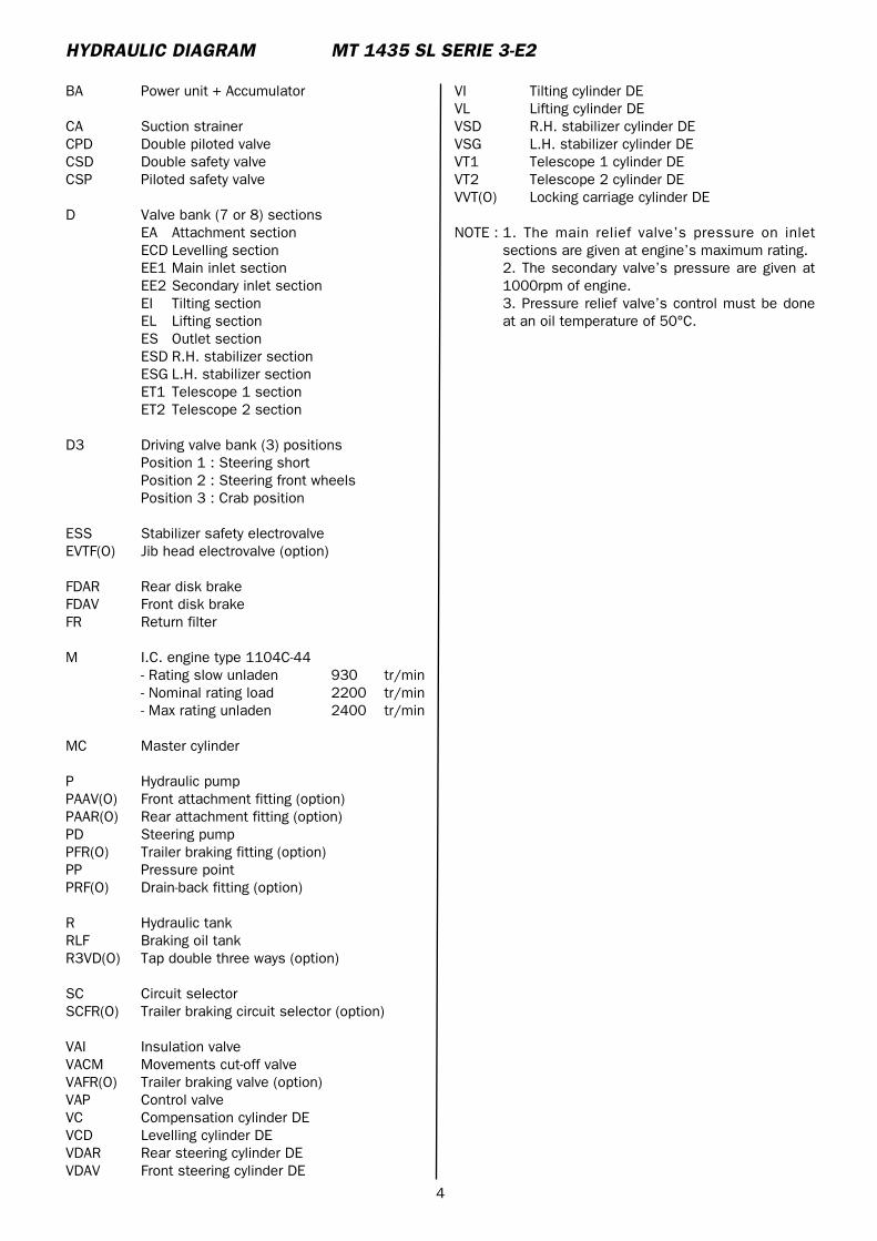
4
BA Power unit + Accumulator
CA Suction strainerCPD Double piloted valveCSD Double safety valveCSP Piloted safety valve
D Valve bank (7 or 8) sectionsEA Attachment sectionECD Levelling sectionEE1 Main inlet sectionEE2 Secondary inlet sectionEI Tilting sectionEL Lifting sectionES Outlet sectionESD R.H. stabilizer sectionESG L.H. stabilizer sectionET1 Telescope 1 sectionET2 Telescope 2 section
D3 Driving valve bank (3) positionsPosition 1 : Steering shortPosition 2 : Steering front wheelsPosition 3 : Crab position
ESS Stabilizer safety electrovalveEVTF(O) Jib head electrovalve (option)
FDAR Rear disk brakeFDAV Front disk brakeFR Return filter
M I.C. engine type 1104C-44- Rating slow unladen 930 tr/min- Nominal rating load 2200 tr/min- Max rating unladen 2400 tr/min
MC Master cylinder
P Hydraulic pumpPAAV(O) Front attachment fitting (option)PAAR(O) Rear attachment fitting (option)PD Steering pumpPFR(O) Trailer braking fitting (option)PP Pressure pointPRF(O) Drain-back fitting (option)
R Hydraulic tankRLF Braking oil tankR3VD(O) Tap double three ways (option)
SC Circuit selectorSCFR(O) Trailer braking circuit selector (option)
VAI Insulation valveVACM Movements cut-off valveVAFR(O) Trailer braking valve (option)VAP Control valveVC Compensation cylinder DEVCD Levelling cylinder DEVDAR Rear steering cylinder DEVDAV Front steering cylinder DE
HYDRAULIC DIAGRAM MT 1435 SL SERIE 3-E2
VI Tilting cylinder DEVL Lifting cylinder DEVSD R.H. stabilizer cylinder DEVSG L.H. stabilizer cylinder DEVT1 Telescope 1 cylinder DEVT2 Telescope 2 cylinder DEVVT(O) Locking carriage cylinder DE
NOTE : 1. The main relief valve’s pressure on inletsections are given at engine’s maximum rating.2. The secondary valve’s pressure are given at1000rpm of engine.3. Pressure relief valve’s control must be doneat an oil temperature of 50°C.
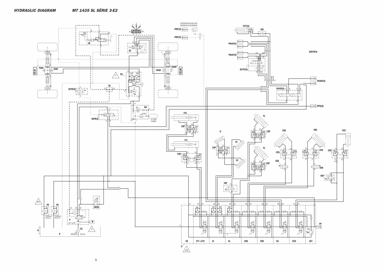
5
HYDRAULIC DIAGRAM MT 1435 SL SÉRIE 3-E2
B A
B A
E
BA BA
E
C1 C2
C3C4
P1 P2
OPTION RETOUR DE FUITEINTERIEUR OU EXTERIEUR
B
TP
N
A
B
B2 A2A6B6
300b
V1 V2
C1 C2300b
C2 C1280b
V2 V1
100b
200bC1
W
V1
K350b
C2
V2
32
1
3 2 1AV AR
200b
LS
T P
R L
P
3 2 1
TA B
200b
140b
200 cm3 /tr
P2 T
45±5b
35b
P1
U
13 BARS0,7 LITRE
100 L/mn140
MICRONS
CFLS EF2b
10 Microns
2b
10 Microns
43.77 cm3/tr
150 L/mn 150 L/mn
A3B3A4
280b
B4
280b
A5B5A7
190b
B7T2
T1
B1 A1 P
260b
180b
C2C1280b
V2V1
100b
200bC1
W
V1
K350b
C2
V2
A
B
C2325b
V2
C1325b
V1Ø1
V2V1
C1 C2
V2V1
C1 C2
A
B B
A
255787a
VACM
R3VD(O)
PAAR(O)
PAAV(O)
EVTF(O)
PAAV(O)
VAIVVT(O)
PRF(O)
PRF(O)
VAFR(O)
PFR(O)
VAP
EA ECD
CSD
VT2
VT1
VSD
CPD
FDARVDAR
FDAV VDAV
PD
D3
BA
M
FRFR
R
P
ESDEL ESGEI
D
ES
PP
EE1ET1 + ET2
CA
CPD
VSG
VC
VI
VL
CSPVC
VL
CSP
N
VAP
CPD
VCD
CSP
CSP
ESS
ESS
FT
FT
FT
FT
110b
110b 315b
315b
ES.A
V.
ES.A
R.
Y
MP
NLB
RLF
B
AV1 V2
SCSCFR(O)

HYDRAULIC DIAGRAM
70-6-255788 EN
20 / 12 / 2006
MT 1435 SL Série 3-E2MT 1435 SL Turbo Série 3-E2MT 1440 SL Série 3-E2MT 1440 SL Turbo Série 3-E2MT 1440 SL Turbo ULTRA Série 3-E2MT 1440 SL Turbo MONO-ULTRA NACELLE ORH Série 3-E2MT 1440 SL Turbo ULTRA NACELLE ORH RC Série 3-E2

3
CONTENTS
– HYDRAULIC DIAGRAM
MT 1435 SL Turbo / MT 1440 SL / MT 1440 SL Turbo Série 3-E2 . . . . 4
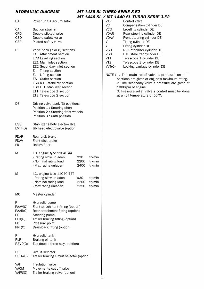
4
BA Power unit + Accumulator
CA Suction strainerCPD Double piloted valveCSD Double safety valveCSP Piloted safety valve
D Valve bank (7 or 8) sectionsEA Attachment sectionECD Levelling sectionEE1 Main inlet sectionEE2 Secondary inlet sectionEI Tilting sectionEL Lifting sectionES Outlet sectionESD R.H. stabilizer sectionESG L.H. stabilizer sectionET1 Telescope 1 sectionET2 Telescope 2 section
D3 Driving valve bank (3) positionsPosition 1 : Steering shortPosition 2 : Steering front wheelsPosition 3 : Crab position
ESS Stabilizer safety electrovalveEVTF(O) Jib head electrovalve (option)
FDAR Rear disk brakeFDAV Front disk brakeFR Return filter
M I.C. engine type 1104C-44- Rating slow unladen 930 tr/min- Nominal rating load 2200 tr/min- Max rating unladen 2400 tr/min
M I.C. engine type 1104C-44T- Rating slow unladen 930 tr/min- Nominal rating load 2200 tr/min- Max rating unladen 2350 tr/min
MC Master cylinder
P Hydraulic pumpPAAV(O) Front attachment fitting (option)PAAR(O) Rear attachment fitting (option)PD Steering pumpPFR(O) Trailer braking fitting (option)PP Pressure pointPRF(O) Drain-back fitting (option)
R Hydraulic tankRLF Braking oil tankR3VD(O) Tap double three ways (option)
SC Circuit selectorSCFR(O) Trailer braking circuit selector (option)
VAI Insulation valveVACM Movements cut-off valveVAFR(O) Trailer braking valve (option)
HYDRAULIC DIAGRAM MT 1435 SL TURBO SERIE 3-E2MT 1440 SL / MT 1440 SL TURBO SERIE 3-E2
VAP Control valveVC Compensation cylinder DEVCD Levelling cylinder DEVDAR Rear steering cylinder DEVDAV Front steering cylinder DEVI Tilting cylinder DEVL Lifting cylinder DEVSD R.H. stabilizer cylinder DEVSG L.H. stabilizer cylinder DEVT1 Telescope 1 cylinder DEVT2 Telescope 2 cylinder DEVVT(O) Locking carriage cylinder DE
NOTE : 1. The main relief valve’s pressure on inletsections are given at engine’s maximum rating.2. The secondary valve’s pressure are given at1000rpm of engine.3. Pressure relief valve’s control must be doneat an oil temperature of 50°C.
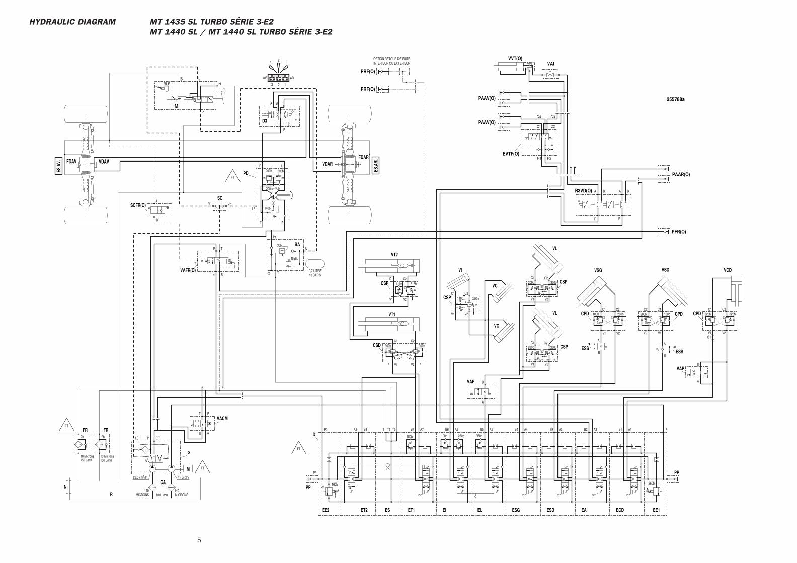
5
HYDRAULIC DIAGRAM MT 1435 SL TURBO SÉRIE 3-E2MT 1440 SL / MT 1440 SL TURBO SÉRIE 3-E2
B A
B A
P
AB
T
E
BA BA
E
C1 C2
C3C4
P1 P2
OPTION RETOUR DE FUITEINTERIEUR OU EXTERIEUR
B
TP
N
B
A
B2 A2
A
B
A6B6
300b
V1 V2
C1 C2300b
C2 C1280b
V2 V1
100b
200bC1
W
V1
K350b
C2
V2
32
1
3 2 1
AV AR
200b
V1 V2LS
T P
R L
P
3 2 1
TA B
200b
140b
200 cm3 /tr
P2 T
45±5b
35b
P1
U
13 BARS0,7 LITRE
100 L/mn140
MICRONS
PLS EF2b
10 Microns
2b
10 Microns
28.5 cm3/tr 41 cm3/tr
150 L/mn 150 L/mn
B8 A3B3A4
280b
B4
280b
A5B5A7
190b
B7T2T T1A8P2
160b
P3
B1 A1 P
260b
180b
C2C1280b
V2V1
100b
200bC1
W
V1
K350b
C2
V2
A
B
C2325b
V2
C1325b
V1Ø1
V2V1
C1 C2
V2V1
C1 C2
MICRONS140
B
AA
B
255788a
VACM
R3VD(O)
PAAR(O)
PAAV(O)
EVTF(O)
PAAV(O)
VAIVVT(O)
PRF(O)
PRF(O)
SCFR(O)
VAFR(O)
PFR(O)
EA
VAP
M
ECD
CSD
VT2
VT1
VSD
CPD
FDARVDARFDAV VDAV
SC
PD
D3
BA
M
FRFR
R
P
ESDEL ESGEI
D
ESET2EE2
PP
PP
EE1ET1
CA
CPD
VSG
VC
VI
VL
CSP
VC
VL
CSP
N
VAP
CPD
VCD
CSP
CSP
ESSESS
FT
FT
FT
FT
P
NLB
RLF
110b
110b 315b
315b
ES.A
V.
ES.A
R.
Y

HYDRAULIC DIAGRAM
70-6-255789 EN
20 / 12 / 2006
MT 1435 SL Série 3-E2MT 1435 SL Turbo Série 3-E2MT 1440 SL Série 3-E2MT 1440 SL Turbo Série 3-E2MT 1440 SL Turbo ULTRA Série 3-E2MT 1440 SL Turbo MONO-ULTRA NACELLE ORH Série 3-E2MT 1440 SL Turbo ULTRA NACELLE ORH RC Série 3-E2

3
CONTENTS
– HYDRAULIC DIAGRAM
MT 1440 SL Turbo ULTRA Série 3-E2 . . . . . . . . . . . . . . . . . . . . . . . . . . 4
4
AD Depressurization accumulator
BA Power unit + Accumulator
CA Suction strainerCPD Double piloted valveCSD Double safety valveCSP Piloted safety valve
D Valve bank (3) sectionsEA Attachment sectionED Levelling sectionEE Inlet sectionET2 Telescope 2 section
D Valve bank (5) sectionsEE Inlet sectionEI Tilting sectionEL Lifting sectionESD R.H. stabilizer sectionESG L.H. stabilizer sectionET1 Telescope 1 section
D3 Driving valve bank (3) positionsPosition 1 : Steering shortPosition 2 : Steering front wheelsPosition 3 : Crab position
FDAR Rear disk brakeFDAV Front disk brakeFHP High pressure filterFR Return filter
M I.C. engine type 1104C-44T- Rating slow unladen 930 tr/min- Nominal rating load 2200 tr/min- Max rating unladen 2350 tr/min
MC Master cylinder
N Level
P Hydraulic pumpPAAV(O) Front attachment fitting (option)PD Steering pumpPP Pressure pointPRF(O) Drain-back fitting (option)
R Hydraulic tankRLF Braking oil tank
SC Circuit selector
VC Compensation cylinder DEVCD Levelling cylinder DEVDAR Rear steering cylinder DEVDAV Front steering cylinder DEVI Tilting cylinder DEVL Lifting cylinder DEVSD R.H. stabilizer cylinder DEVSG L.H. stabilizer cylinder DEVT1 Telescope 1 cylinder DE
HYDRAULIC DIAGRAM MT 1440 SL TURBO ULTRA SERIE 3-E2
VT2 Telescope 2 cylinder DEVVT(O) Locking carriage cylinder DE
NOTE : 1. The main relief valve’s pressure on inletsections are given at engine’s maximum rating.2. The secondary valve’s pressure are given at1000rpm of engine.3. Pressure relief valve’s control must be doneat an oil temperature of 50°C.
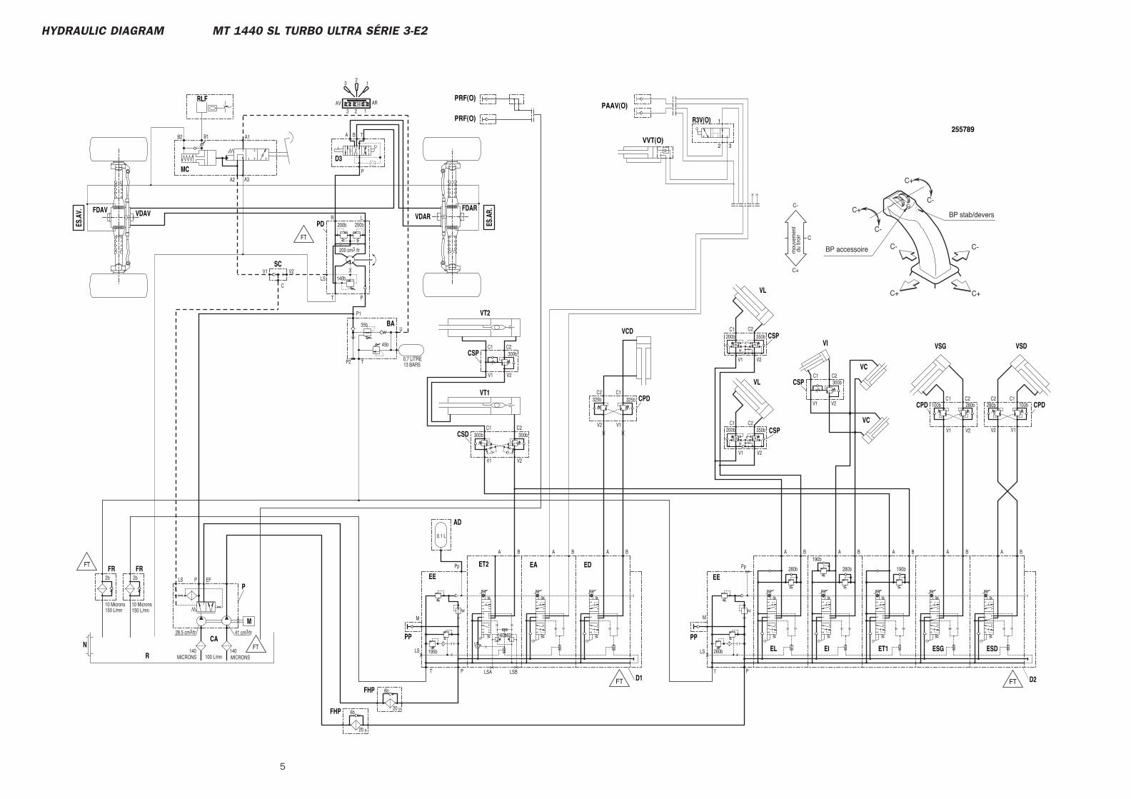
5
HYDRAULIC DIAGRAM MT 1440 SL TURBO ULTRA SÉRIE 3-E2
C+
C-
C
BP accessoire
BP stab/deversC+
C-C-
C-
C-
C+C+
C+
1
2 3
140MICRONS
160160b
6b
6b
280bX
XX
X260b
Pp
LS
M
PT
X195b
Pp
13 BARS0,7 LITRE
U
P1
35b
45b
TP2
20 μ
0.1 L
190b280b
190b
V2
C2350b
K
V1
W
V1 V2
C1200b
100b
V1 V2
280b
C1 C2300b
C1 C2
A B
150 L/mn150 L/mn
41 cm3/tr28.5 cm3/tr
10 Microns
2b
10 Microns
2b EFLS P
MICRONS140
100 L/mn
200 cm3 /tr
140b
200b
BA T
123
P
LR
PT
LS
A1
A3A2
B2 B1
V2V1
200b
ARAV123
12
3
AB
V2
C2350b
K
V1
W
C1200b
AB
100b
V1V2
280bC1C2
C
300bC2C1
V2V1
300b
300bC2C1
V2V1
B B B BA A A AA B
LS
M
PT
BA
LSA LSB
20 μ
BA
325b
V1V2
325bC1C2
255789R3V(O)
VVT(O)
PAAV(O)
PRF(O)
PRF(O)
EE
PP
EE
BA
FHP
AD
ESDESGET1EIN
CSP
CSP
VL
VCCSP
VL
VI
VC
VSG
CPD
CAEL
P
R
FR FR
M
D3
PD
MC
RLF
SC
VDAVFDAVVDAR
FDAR
CPD
VSD
VT1
VT2
CSD
CSP
EA
PP
ET2
FHPD2
ED
D1
CPD
VCD
FT
FT
FT
FT FT
ES.A
V.
ES.A
R.
mou
vem
ent
du
tiroi
r

HYDRAULIC DIAGRAM
70-6-255790 EN
20 / 12 / 2006
MT 1435 SL Série 3-E2MT 1435 SL Turbo Série 3-E2MT 1440 SL Série 3-E2MT 1440 SL Turbo Série 3-E2MT 1440 SL Turbo ULTRA Série 3-E2MT 1440 SL Turbo MONO-ULTRA NACELLE ORH Série 3-E2MT 1440 SL Turbo ULTRA NACELLE ORH RC Série 3-E2


3
CONTENTS
– HYDRAULIC DIAGRAM
MT 1440 SL Turbo MONO-ULTRA NACELLE ORH Série 3-E2 . . . . . . . . . . 4
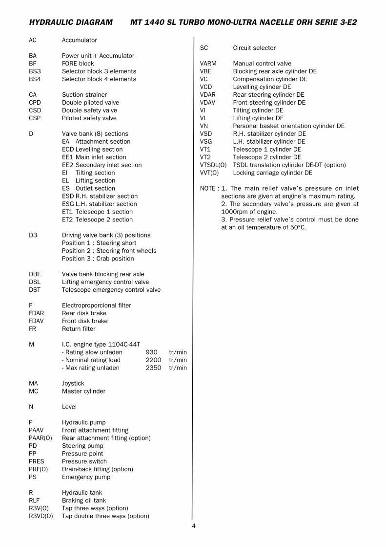
4
AC Accumulator
BA Power unit + AccumulatorBF FORE blockBS3 Selector block 3 elementsBS4 Selector block 4 elements
CA Suction strainerCPD Double piloted valveCSD Double safety valveCSP Piloted safety valve
D Valve bank (8) sectionsEA Attachment sectionECD Levelling sectionEE1 Main inlet sectionEE2 Secondary inlet sectionEI Tilting sectionEL Lifting sectionES Outlet sectionESD R.H. stabilizer sectionESG L.H. stabilizer sectionET1 Telescope 1 sectionET2 Telescope 2 section
D3 Driving valve bank (3) positionsPosition 1 : Steering shortPosition 2 : Steering front wheelsPosition 3 : Crab position
DBE Valve bank blocking rear axleDSL Lifting emergency control valveDST Telescope emergency control valve
F Electroproporcional filterFDAR Rear disk brakeFDAV Front disk brakeFR Return filter
M I.C. engine type 1104C-44T- Rating slow unladen 930 tr/min- Nominal rating load 2200 tr/min- Max rating unladen 2350 tr/min
MA JoystickMC Master cylinder
N Level
P Hydraulic pumpPAAV Front attachment fittingPAAR(O) Rear attachment fitting (option)PD Steering pumpPP Pressure pointPRES Pressure switchPRF(O) Drain-back fitting (option)PS Emergency pump
R Hydraulic tankRLF Braking oil tankR3V(O) Tap three ways (option)R3VD(O) Tap double three ways (option)
HYDRAULIC DIAGRAM MT 1440 SL TURBO MONO-ULTRA NACELLE ORH SERIE 3-E2
SC Circuit selector
VARM Manual control valveVBE Blocking rear axle cylinder DEVC Compensation cylinder DEVCD Levelling cylinder DEVDAR Rear steering cylinder DEVDAV Front steering cylinder DEVI Tilting cylinder DEVL Lifting cylinder DEVN Personal basket orientation cylinder DEVSD R.H. stabilizer cylinder DEVSG L.H. stabilizer cylinder DEVT1 Telescope 1 cylinder DEVT2 Telescope 2 cylinder DEVTSDL(O) TSDL translation cylinder DE-DT (option)VVT(O) Locking carriage cylinder DE
NOTE : 1. The main relief valve’s pressure on inletsections are given at engine’s maximum rating.2. The secondary valve’s pressure are given at1000rpm of engine.3. Pressure relief valve’s control must be doneat an oil temperature of 50°C.
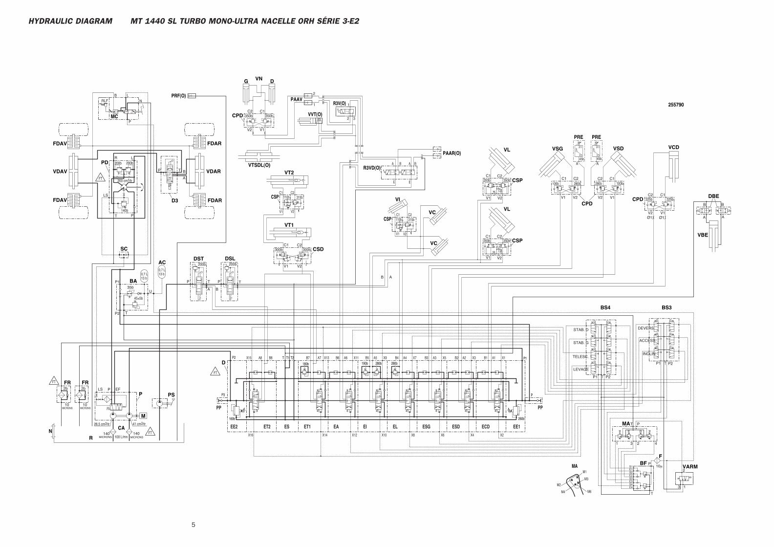
5
HYDRAULIC DIAGRAM MT 1440 SL TURBO MONO-ULTRA NACELLE ORH SÉRIE 3-E2
1
2
32
1
E
A BA B
E
A7B8 B7 A2B2A3B3A4B4A5B5A6B6A8 B1 A1
V2 V1
M2
M1
M6M4
M3
1
23
A
1
23
A
V2V1
C1 C2
V2V1
C1 C2
350bC2 C1
350b
140MICRONS
200b200b
45b45b
350bK
C
C2
W
200bC1
V2V1
C
100 L/mn140
MICRONS
140b
200 cm3/tr
200b200b
10μ
INCLIN.
ACCESS.
DEVERS
LEVAGE
TELESC. 1
STAB. G
STAB. D
2
3 1
T P2P1
P1 P2T
E4S4E3S3E2S2E1S1
T
P
T P
1 23 4
U
P135b
45±5b
TP2
ABTP
A B
TP
C1325b
V1
C2325b
V2
C1100b
V1
C2C2C1C1
200b 350bC2
280b
V2
280b
V2V1
100bK
W
V1 V2
300bC2C1
V2V1
B
A
TP
300b
LR
P
LS
T
PLS EF2b
10MICRONS
2b
10MICRONS
28,5 cm3/tr 41 cm3/tr
1
2
3
13 b0,7 L
13 b0,7 L
Ø1 Ø1
B
AA
B
CAN
255790R3V(O)
VTSDL(O)
PAAR(O)
R3VD(O)
PRF(O)
P
280b280b190bT2T T1P2
160b
P3
P1
260b
180b
CPD
VNG D
VVT(O)
PAAV
MA
MC
CSP
FBF
VARM
BS3BS4
MA
BA
DSLDST
PS
CPD
VCDVSD
CPD
VSG
VC
VI
VL
VC
VL
CSP
VT2
FDAR
VT1
CSD
VDAR
FDARD3
FDAV
PD
VDAV
SC
FDAV
M
FRFR
R
P
PRE PRE
AC
CSP
CSP
VBE
DBE
FT
FT
FT
FT
ESDEL ESGEIEAESET2EE2
PP
ECD
PP
EE1ET1
P
N
LBRLF
110b
110b
315b
315b
X4X6X8X10X12X16
X15 X13 X11 X9 X7 X5
X2
X3 X1
X14
D

HYDRAULIC DIAGRAM
70-6-255791 EN
20 / 12 / 2006
MT 1435 SL Série 3-E2MT 1435 SL Turbo Série 3-E2MT 1440 SL Série 3-E2MT 1440 SL Turbo Série 3-E2MT 1440 SL Turbo ULTRA Série 3-E2MT 1440 SL Turbo MONO-ULTRA NACELLE ORH Série 3-E2MT 1440 SL Turbo ULTRA NACELLE ORH RC Série 3-E2

3
CONTENTS
– HYDRAULIC DIAGRAM
MT 1440 SL Turbo MONO-ULTRA NACELLE ORH Série 3-E2 . . . . . . . . . . 4
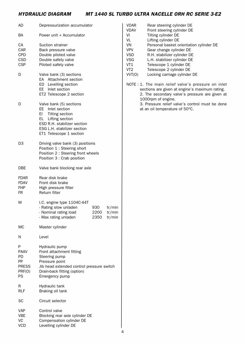
4
AD Depressurization accumulator
BA Power unit + Accumulator
CA Suction strainerCAR Back pressure valveCPD Double piloted valveCSD Double safety valveCSP Piloted safety valve
D Valve bank (3) sectionsEA Attachment sectionED Levelling sectionEE Inlet sectionET2 Telescope 2 section
D Valve bank (5) sectionsEE Inlet sectionEI Tilting sectionEL Lifting sectionESD R.H. stabilizer sectionESG L.H. stabilizer sectionET1 Telescope 1 section
D3 Driving valve bank (3) positionsPosition 1 : Steering shortPosition 2 : Steering front wheelsPosition 3 : Crab position
DBE Valve bank blocking rear axle
FDAR Rear disk brakeFDAV Front disk brakeFHP High pressure filterFR Return filter
M I.C. engine type 1104C-44T- Rating slow unladen 930 tr/min- Nominal rating load 2200 tr/min- Max rating unladen 2350 tr/min
MC Master cylinder
N Level
P Hydraulic pumpPAAV Front attachment fittingPD Steering pumpPP Pressure pointPRESS Jib head extended control pressure switchPRF(O) Drain-back fitting (option)PS Emergency pump
R Hydraulic tankRLF Braking oil tank
SC Circuit selector
VAP Control valveVBE Blocking rear axle cylinder DEVC Compensation cylinder DEVCD Levelling cylinder DE
HYDRAULIC DIAGRAM MT 1440 SL TURBO ULTRA NACELLE ORH RC SERIE 3-E2
VDAR Rear steering cylinder DEVDAV Front steering cylinder DEVI Tilting cylinder DEVL Lifting cylinder DEVN Personal basket orientation cylinder DEVPV Gear change cylinder DEVSD R.H. stabilizer cylinder DEVSG L.H. stabilizer cylinder DEVT1 Telescope 1 cylinder DEVT2 Telescope 2 cylinder DEVVT(O) Locking carriage cylinder DE
NOTE : 1. The main relief valve’s pressure on inletsections are given at engine’s maximum rating.2. The secondary valve’s pressure are given at1000rpm of engine.3. Pressure relief valve’s control must be doneat an oil temperature of 50°C.
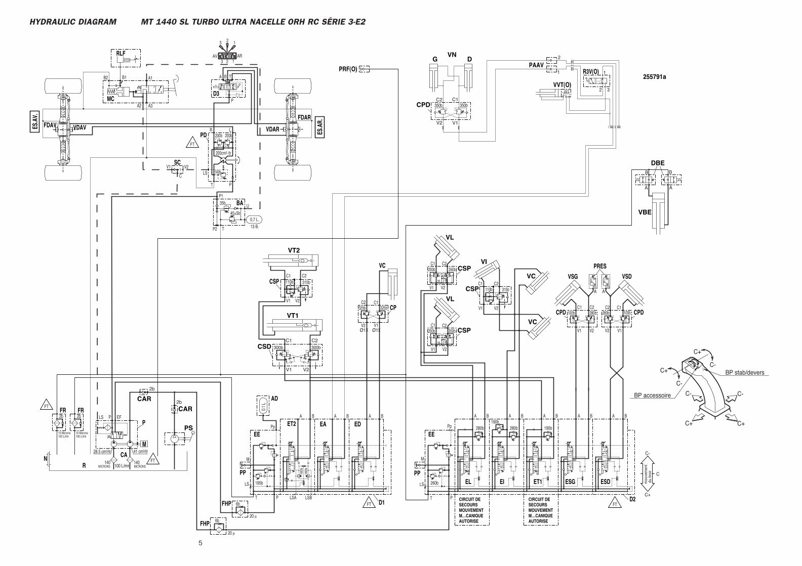
5
HYDRAULIC DIAGRAM MT 1440 SL TURBO ULTRA NACELLE ORH RC SÉRIE 3-E2
6b
6b
20 μ
20 μ
mou
vem
ent
du
tiroi
r
C+
C+ C+
C-
C-
C- C-
C+ BP stab/devers
BP accessoire
C
C-
C+
2
1
V1V2
32
1
160b
160b
315b110bC2C1
V1 V2
45±5b
Ø1Ø1
C2C1
V1 V2
A BBA190b
280b
T P
M
LS
Pp
260bX
X 280b
T P
A B
LSBLSA
A B
M
LS
BA
0.1
L
Pp
195bX
X X
13 B.0,7 L.
U
P135b
TP2
190b
100b
V1 V2
280bC1 C2
150 L/mn150 L/mn
41 cm3/tr28.5 cm3/tr
10 Microns
2b
10 Microns
2b EFLS P
MICRONS140
100 L/mn
200cm3 /tr
140b
200b
BA T
123
P
LR
PT
LS
A1
A3A2
B2 B1
V2V1
200b
ARAV123
123
100b
V1V2
280bC1C2
C
B B BA A A
325b
V1V2
325bC1C2
45b45b
A
3 2
1
A
3 2
1
V1 V2
C1200b
W
C2
C
K350b
B A
V1 V2
C1200b
W
C2
K350b
B A
140MICRONS
255791a
DGVN
CPD
R3V(O)
VVT(O)
PRF(O)
DBE
VBE
VC
VC
VI
CSP
CSD
CSP
VT1
VT2
PS
CAR
EL EIPP
EE
EDET2
PP
EA
AD
EE
BA
FHP
ESDESGET1
N
VSG
CPD
P
R
FR FR
M
D3
PD
MC
RLF
SC
VDAVFDAVES.A
V.
VDAR
FDAR
CPD
VSD
FHPD2D1
CP
VC PRES
CAR
CIRCUIT DE SECOURSMOUVEMENT M…CANIQUEAUTORISE
CSP
VL
VL
CSP
CIRCUIT DE SECOURSMOUVEMENT M…CANIQUEAUTORISE
PAAV
CA
350bC1C2
350b
B
A A
B
300b
V1 V2
C1 C2300b
2b
2b
C
FT
FT
FT
FT FT
315b110b
ES.A
R.


MT 1740 SL Turbo Série 3-E2
15 / 11 / 2007
HYDRAULIC DIAGRAM
70-6-245213 EN

2 15/11/200770-6-245213EN
3 70-6-245213EN15/11/2007
-HYDRAULIC DIAGRAM
MT 1740 SL Turbo Série 3-E2 . . . . . . . . . . . . . . . . . . . . . . . . . . . . . . . . . . . . . . . . . . . . 4
CONTENTS
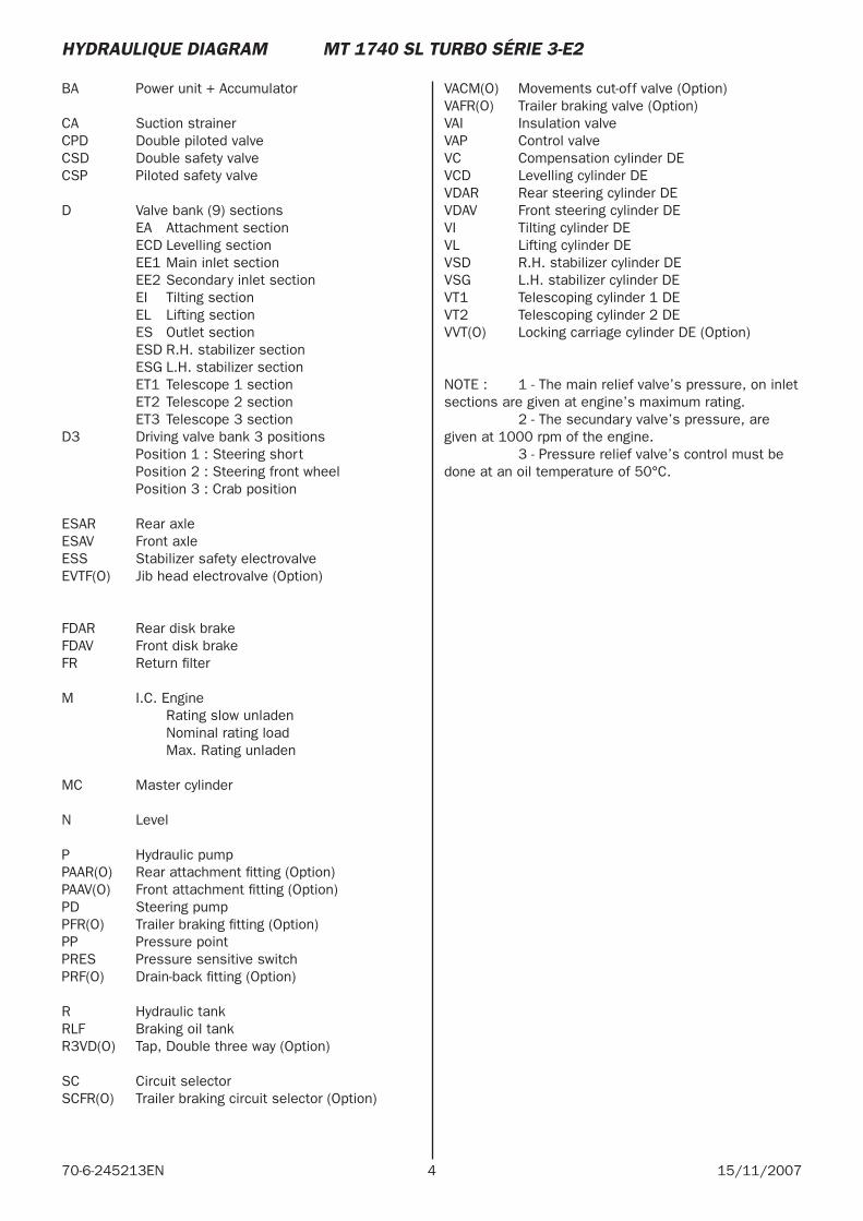
4 15/11/200770-6-245213EN
BA Power unit + Accumulator
CA Suction strainerCPD Double piloted valveCSD Double safety valveCSP Piloted safety valve
D Valve bank (9) sections EA Attachment section ECD Levelling section EE1 Main inlet section EE2 Secondary inlet section EI Tilting section EL Lifting section ES Outlet section ESD R.H. stabilizer section ESG L.H. stabilizer section ET1 Telescope 1 section ET2 Telescope 2 section ET3 Telescope 3 sectionD3 Driving valve bank 3 positions Position 1 : Steering short Position 2 : Steering front wheel Position 3 : Crab position
ESAR Rear axleESAV Front axleESS Stabilizer safety electrovalveEVTF(O) Jib head electrovalve (Option)
FDAR Rear disk brakeFDAV Front disk brakeFR Return fi lter
M I.C. Engine Rating slow unladen Nominal rating load Max. Rating unladen
MC Master cylinder
N Level
P Hydraulic pump PAAR(O) Rear attachment fi tting (Option) PAAV(O) Front attachment fi tting (Option) PD Steering pumpPFR(O) Trailer braking fi tting (Option)PP Pressure pointPRES Pressure sensitive switchPRF(O) Drain-back fi tting (Option)
R Hydraulic tankRLF Braking oil tankR3VD(O) Tap, Double three way (Option)
SC Circuit selectorSCFR(O) Trailer braking circuit selector (Option)
VACM(O) Movements cut-off valve (Option) VAFR(O) Trailer braking valve (Option) VAI Insulation valve VAP Control valveVC Compensation cylinder DEVCD Levelling cylinder DEVDAR Rear steering cylinder DEVDAV Front steering cylinder DEVI Tilting cylinder DEVL Lifting cylinder DEVSD R.H. stabilizer cylinder DEVSG L.H. stabilizer cylinder DEVT1 Telescoping cylinder 1 DEVT2 Telescoping cylinder 2 DEVVT(O) Locking carriage cylinder DE (Option)
NOTE : 1 - The main relief valve’s pressure, on inlet sections are given at engine’s maximum rating. 2 - The secundary valve’s pressure, are given at 1000 rpm of the engine. 3 - Pressure relief valve’s control must be done at an oil temperature of 50°C.
HYDRAULIQUE DIAGRAM MT 1740 SL TURBO SÉRIE 3-E2
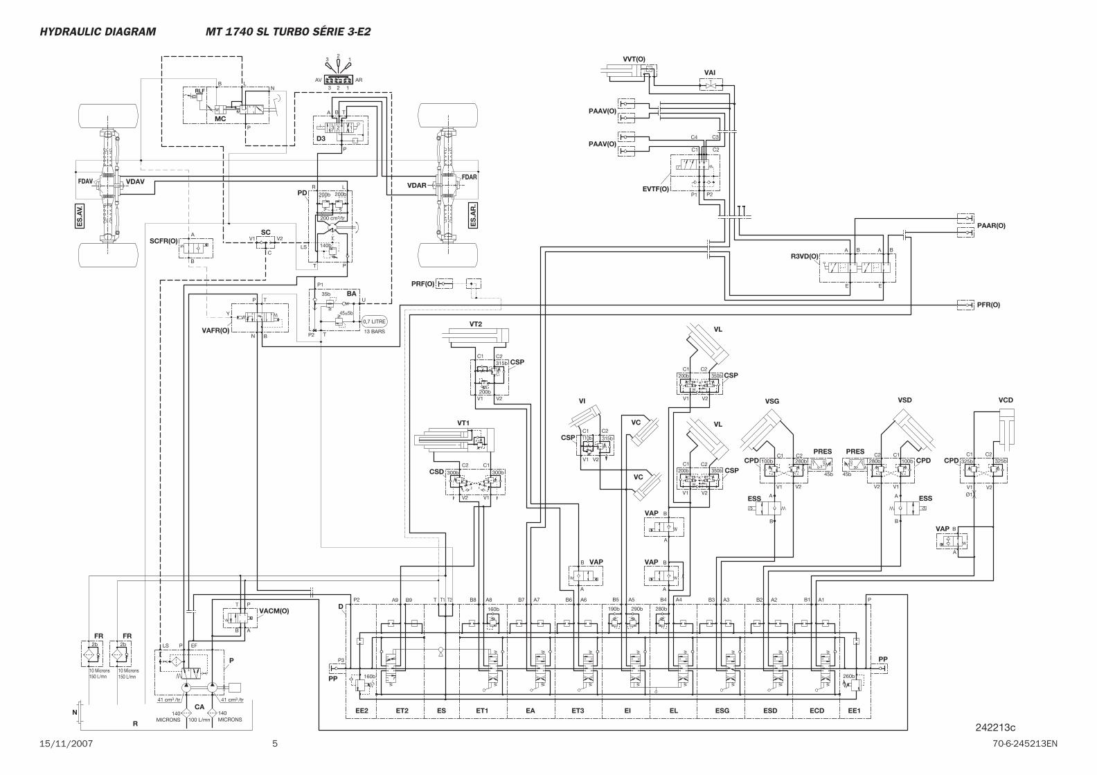
515/11/2007 70-6-245213EN
Y
140MICRONS
A
B
45b300b
V2 V1
C2 C1300b
V2
C2350b
K
V1
W
C1200b
100b
V1 V2
280bC1 C2
V1
325bC1
V2
325bC2
160b
B8 A8
260b
PA1B1
P3
160b
P2 A9 T1T T2 B6 A6 B5
190b
A5 B4 A4
290b
B3
280b
A3 B2 A2B7 A7B9
150 L/mn150 L/mn
41 cm3 /tr41 cm3 /tr
10 Microns
2b
10 Microns
2b EFLS P
MICRONS140
100 L/mn
0,7 LITRE
13 BARS
U
P1
35b
45±5b
TP2
200 cm3/tr
140b
200b
BA T
123
P
LR
PT
LS
V2V1
200b
ARAV
123
12
3
V1 V2
315bC1 C2
200bV2
C2350b
K
V1
W
C1200b
45b
1 23A100b
V1V2
280bC1C2
123 A
C
B
A
B
A
B
A
V2V1
C1 C2
B
A
A
B
B
TP
N
B
A
C1 C2
C3C4
P1 P2
E
BA BA
E
P
AB
T
1
2
AB
AB
VAP
MC
N
CSD
VT2
CSP
VL
VCCSP
VL
VI
VC
VSG
CPD
VCD
CA ET1 EE1
PP
ECD
PP
EE2 ET2 ES
D
ET3EA EI ESGEL ESD
P
R
FR FR
BA
D3
PD
SC
VDAVFDAVVDAR
FDAR
CSP
VT1
CPDPRES
CPDPRES
VSD
VAP
ESS
VAP
CSP
VAP
ESS
SCFR(O)
VAFR(O)
PFR(O)
PRF(O)
VAI
VVT(O)
PAAV(O)
PAAV(O)
EVTF(O)
R3VD(O)
PAAR(O)
VACM(O)
ES
.AV.
ES
.AR
.
P
NLB
RLF
110b 315b
242213c
Ø1
HYDRAULIC DIAGRAM MT 1740 SL TURBO SÉRIE 3-E2

6 15/11/200770-6-245213EN
MT 1740 SL Turbo Ultra Série 3-E2
15 / 11 / 2007
HYDRAULIC DIAGRAM
70-6-241702 EN

2 15/11/200770-6-241702EN

3 70-6-241702EN15/11/2007
-HYDRAULIC DIAGRAM
MT 1740 SL Turbo Ultra Série 3-E2 Légende . . . . . . . . . . . . . . . . . 4
MT 1740 SL Turbo Ultra Série 3-E2 N°: 206188. . . . . . . . . . . 5
MT 1740 SL Turbo Ultra Série 3-E2 N°: 206189 . . . . . . . . . . . 7
CONTENTS
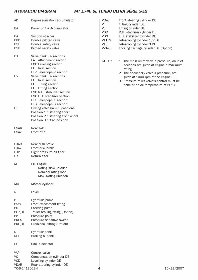
4 15/11/200770-6-241702EN
AD Depressurization accumulator
BA Power unit + Accumulator
CA Suction strainerCPD Double piloted valveCSD Double safety valveCSP Piloted safety valve
D1 Valve bank (3) sections EA Attachment section ECD Levelling section EE Inlet section ET2 Telescope 2 sectionD2 Valve bank (6) sections EE Inlet section EI Tilting section EL Lifting section ESD R.H. stabilizer section ESG L.H. stabilizer section ET1 Telescope 1 section ET3 Telescope 3 sectionD3 Driving valve bank 3 positions Position 1 : Steering short Position 2 : Steering front wheel Position 3 : Crab position
ESAR Rear axleESAV Front axle
FDAR Rear disk brakeFDAV Front disk brakeFHP Hight pressure oil fi lterFR Return fi lter
M I.C. Engine Rating slow unladen Nominal rating load Max. Rating unladen
MC Master cylinder
N Level
P Hydraulic pumpPAAV Front attachment fi tting PD Steering pumpPFR(O) Trailer braking fi tting (Option)PP Pressure pointPRES Pressure sensitive switchPRF(O) Drain-back fi tting (Option)
R Hydraulic tankRLF Braking oil tank
SC Circuit selector
VAP Control valveVC Compensation cylinder DEVCD Levelling cylinder DEVDAR Rear steering cylinder DE
VDAV Front steering cylinder DEVI Tilting cylinder DEVL Lifting cylinder DEVSD R.H. stabilizer cylinder DEVSG L.H. stabilizer cylinder DEVT1/2 Telescoping cylinder 1/2 DEVT3 Telescoping cylinder 3 DEVVT(O) Locking carriage cylinder DE (Option)
NOTE : 1 - The main relief valve’s pressure, on inlet sections are given at engine’s maximum rating.
2 - The secundary valve’s pressure, are given at 1000 rpm of the engine.
3 - Pressure relief valve’s control must be done at an oil temperature of 50°C.
HYDRAULIC DIAGRAM MT 1740 SL TURBO ULTRA SÉRIE 3-E2
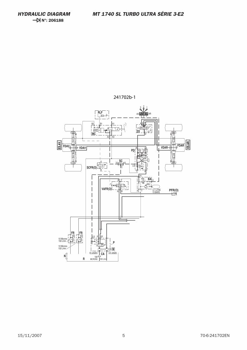
5 70-6-241702EN15/11/2007
HYDRAULIC DIAGRAM MT 1740 SL TURBO ULTRA SÉRIE 3-E2 N°: 206188
13 BARS0,7 LITRE
U
P140b
45b
TP2
150 L/mn
150 L/mn
41 cm3/tr41 cm3/tr
10 Microns2b
10 Microns
2b EFLS P
MICRONS100
100 L/mn
200 cm3 /tr
140b
200b
BA T
123
P
LR
PT
LS
A1
A3A2
B2 B1
V2V1
200b
ARAV123
123
C
A
B
N
P T
B
BA
NCA
P
R
FR FR
M
D3
PD
MC
RLF
SC
VDAVFDAV VDARFDAR
PFR(O)VAFR(O)
SCFR(O)
Y
ES.A
V.
ES.A
R.
241702b-1
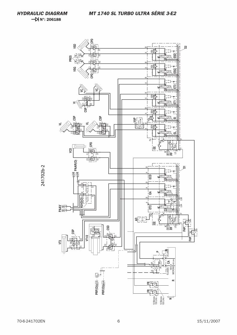
6 15/11/200770-6-241702EN
HYDRAULIC DIAGRAM MT 1740 SL TURBO ULTRA SÉRIE 3-E2 N°: 206188
AB
80b
80b
AB
BA
190b
280b
TP
M
LS
Pp
260b
X
X
280b
TP
AB
LSB
LSA
X
AB
M LS
BA
0.1
L
Pp
195b
X
X
X
160b
V2
C235
0bK
V1W
V1V2
C1 200b
100b
V1V228
0b
C1C2 30
0b
C1C2
150
L/m
n
150
L/m
n
41 cm
3/tr
41 cm
3/tr
10 M
icron
s2b
10 M
icron
s
2bEF
LSP
MIC
RONS
100
100
L/m
n
V2
C235
0bK
V1W
C1 200b
100b
V1V2280b
C1C2
BB
BA
AA
325b
V1V232
5bC1
C2
300b
200b
C2C1
V2V1
100b
32
1
300b
V1V2
C1C2
300b
BA
45b
45b
A
32 1
A
32 1
EAB
AB
E
6b
6b
20
AB
AB
20
VAP
ELEI
PP
EEEC
DET
2
PP
EA
AD
EE
PAAV
FHP
ESD
ESG
ET1
N
CSP
CSP
VL
VCCS
P
VL
VI
VC
VSG
CPD
CA
P
R
FRFR
M
CPD
VSD
FHP
D2D1
CPD
VCD
CSP
VT1/
2
CSD
VT3
PRES
ET3
PAAR
(O)
R3VD
(O)
PRF(
O)
PRF(
O)
2417
02b
-2
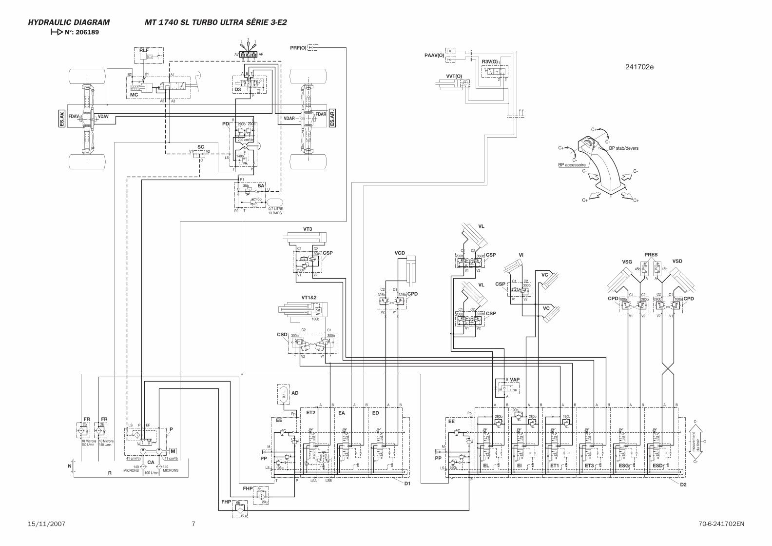
715/11/2007 70-6-241702EN
ES
.AV.
ES
.AR
.
VAP
EL EI
PP
EE
EDET2
PP
EA
AD
EE
BA
FHP
ESDESGET1N
CSP
CSP
VL
VCCSP
VL
VI
VC
VSG
CPD
P
R
FR FR
D3
PD
MC
RLF
SC
VDAVFDAV VDARFDAR
CPD
VSD
FHPD2D1
CPD
VCDCSP
VT3
PRES
ET3
VT1&2
CSD
CA
PRF(O)
PAAV(O)R3V(O)
VVT(O)
160b
160b
A
B
A BBA190b
280b
T P
M
LS
Pp
260bX
X 280b
T P
A B
LSBLSA
X A B
M
LS
BA
0.1
L
Pp
195bX
X X
13 BARS0,7 LITRE
U
P1
35b
45b
TP2
160b
V2
C2350b
K
V1
W
V1 V2
C1200b
100b
V1 V2
280b
C1 C2300b
C1 C2
150 L/mn150 L/mn
41 cm3/tr41 cm3/tr
10 Microns
2b
10 Microns
2b EFLS P
MICRONS140
100 L/mn
200 cm3/tr
140b
200b
BA T
123
P
LR
PT
LS
A1
A3A2
B2 B1
V2V1
200b
ARAV123
12
3
V2
C2
350bK
V1
W
C1
200b
100b
V1V2
280bC1C2
C
B B BA A A
325b
V1V2
325bC1C2
300b
200b
C2C1
V2V1
BA
45b45b
A
3 2
1
A
3 2
1
MICRONS140
1
2 3
6b
6b
20 μ
AB
AB
20 μ
mou
vem
ent
du
tiroi
r
C+
C+ C+
C-
C-
C- C-
C+ BP stab/devers
BP accessoire
C
C-
C+
300b
V1
C1
300b
V2
C2
100b
M
241702e
HYDRAULIC DIAGRAM MT 1740 SL TURBO ULTRA SÉRIE 3-E2 N°: 206189

8 15/11/200770-6-241702EN
MT 1740 SL Turbo Mono Ultra ORH Série 3-E2
15 / 11 / 2007
HYDRAULIC DIAGRAM
70-6-245214 EN

2 15/11/200770-6-245214EN

3 70-6-245214EN15/11/2007
-HYDRAULIC DIAGRAM
MT 1740 SL Turbo Mono Ultra ORH Série 3-E2 Légende . . . . . . . . . . . . . . . . . 4
MT 1740 SL Turbo Mono Ultra ORH Série 3-E2 N°: 204232. . . . . . . . . . . 5
MT 1740 SL Turbo Mono Ultra ORH Série 3-E2 N°: 204233 . . . . . . . . . . . 9
CONTENTS
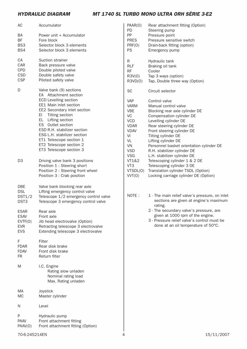
4 15/11/200770-6-245214EN
AC Accumulator
BA Power unit + AccumulatorBF Fore block BS3 Selector block 3 elementsBS4 Selector block 3 elements
CA Suction strainer CAR Back pressure valveCPD Double piloted valveCSD Double safety valveCSP Piloted safety valve
D Valve bank (9) sections EA Attachment section ECD Levelling section EE1 Main inlet section EE2 Secondary inlet section EI Tilting section EL Lifting section ES Outlet section ESD R.H. stabilizer section ESG L.H. stabilizer section ET1 Telescope section 1 ET2 Telescope section 2 ET3 Telescope section 3
D3 Driving valve bank 3 positions Position 1 : Steering short Position 2 : Steering front wheel Position 3 : Crab position
DBE Valve bank blocking rear axleDSL Lifting emergency control valveDST1/2 Telescope 1/2 emergency control valveDST3 Telescope 3 emergency control valve
ESAR Rear axleESAV Front axleEVTF(O) Jib head electrovalve (Option) EVR Retracting telescope 3 electrovalveEVS Extending telescope 3 electrovalve
F Filter FDAR Rear disk brakeFDAV Front disk brakeFR Return fi lter
M I.C. Engine Rating slow unladen Nominal rating load Max. Rating unladen
MA JoystickMC Master cylinder
N Level
P Hydraulic pumpPAAV Front attachment fi ttingPAAV(O) Front attachment fi tting (Option)
PAAR(O) Rear attachment fi tting (Option)PD Steering pump PP Pressure pointPRES Pressure sensitive switchPRF(O) Drain-back fi tting (option)PS Emergency pump
R Hydraulic tankRLF Braking oil tankRF Cooler R3V(O) Tap 3 ways (option)R3VD(O) Tap, Double three way (Option)
SC Circuit selector
VAP Control valveVARM Manual control valveVBE Blocking rear axle cylinder DEVC Compensation cylinder DEVCD Levelling cylinder DEVDAR Rear steering cylinder DEVDAV Front steering cylinder DEVI Tilting cylinder DEVL Lifting cylinder DEVN Personnel basket orientation cylinder DE VSD R.H. stabilizer cylinder DEVSG L.H. stabilizer cylinder DEVT1&2 Telescoping cylinder 1 & 2 DEVT3 Telescoping cylinder 3 DEVTSDL(O) Translation cylinder TSDL (Option)VVT(O) Locking carriage cylinder DE (Option)
NOTE : 1 - The main relief valve’s pressure, on inlet sections are given at engine’s maximum rating.
2 - The secundary valve’s pressure, are given at 1000 rpm of the engine.
3 - Pressure relief valve’s control must be done at an oil temperature of 50°C.
HYDRAULIC DIAGRAM MT 1740 SL TURBO MONO ULTRA ORH SÉRIE 3-E2
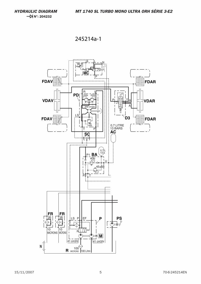
5 70-6-245214EN15/11/2007
HYDRAULIC DIAGRAM MT 1740 SL TURBO MONO ULTRA ORH SÉRIE 3-E2 N°: 204232
AC
P
R
FR FR
M
FDAV
SC
VDAVPD
FDAV
D3 FDAR
VDAR
FDAR
BA
PS
MC
0,7 LITRE13 BARS
41 cm3/tr41 cm3/tr
MICRONS10
2b
MICRONS10
2b EFLS P
T
LS
P
R L
32
P T
A
B1
P2 T
45±5b
40bP1
U
0,7 L13 b
200b 200b
200 cm3/tr
140b
MICRONS100
100 L/mn
RLFB L N
P
N
245214a-1
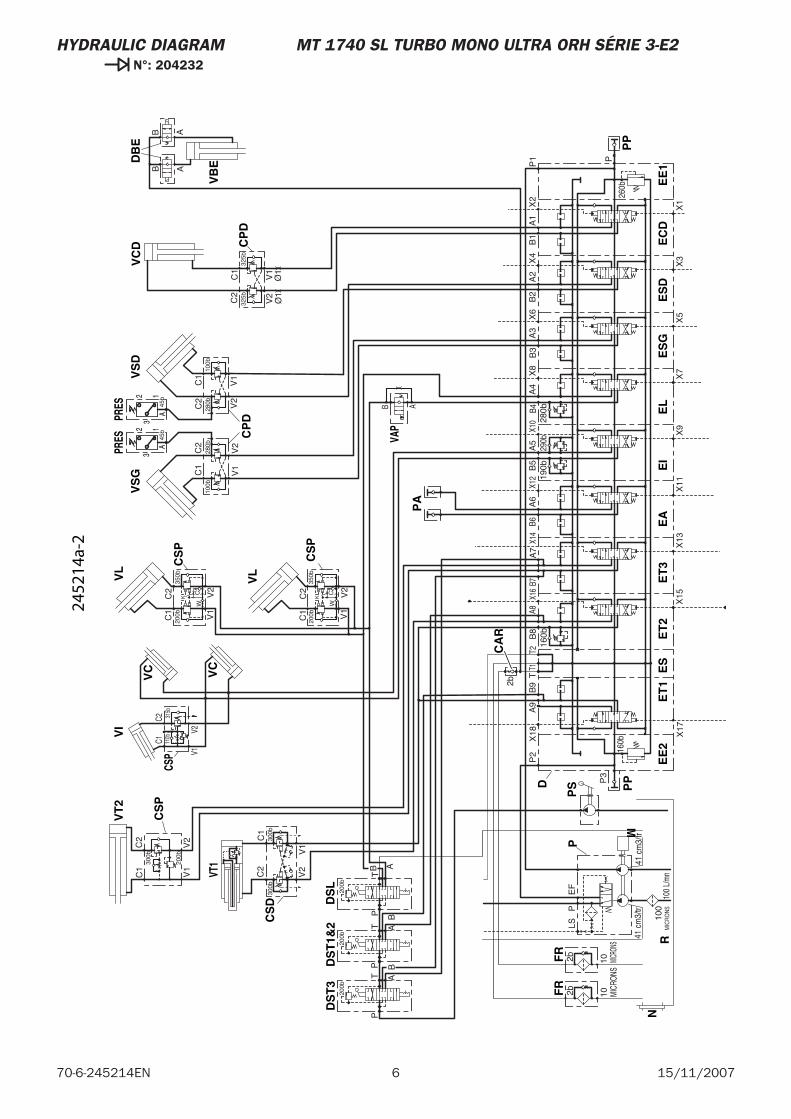
6 15/11/200770-6-245214EN
HYDRAULIC DIAGRAM MT 1740 SL TURBO MONO ULTRA ORH SÉRIE 3-E2 N°: 204232
B A
C2C1
V1V2
VAP
CSP
PRES
A
32 1
PRES
A
32 1
P
RN
FR
FR
M
PP
EE
2E
T1
ES
D
EA
ET
3E
I
PA
ES
GE
LE
SD
EE
1
PP
CS
P
VL
VC
VL
VI
VC
VS
G
CP
D
VS
DV
CD C
PD
EC
DE
T2
CS
D
CS
P
PS
DS
LD
ST
3D
ST
1&2
DB
E
CA
R
VB
E
CS
P
VT
2
VT1
Ø1
Ø1
2b
41 c
m3/
tr41
cm
3/tr
MIC
RONS
102b
MICRO
NS102b
EF
LSP
P3
P2
A9
T1T
T2B6
A6
B5
190b
A5
B4A
429
0bB
328
0bA
3B
2A
2
P
P1
100b
V1
V2
280b
V2
280b
C1
C2
C2
V1
100b
C1
V2
325bC2
V1
325b
C1
A1
B1
B7A
7X
2X
4X
6X
8X1
0X1
2X1
4X
18
X13
X17
X11
X9
X7
X5
X3
X1
MIC
RO
NS
100
100
L/m
n
X15
B8
160b
X16
A8
160b
260b
C2
V2
300b
C1
V1
300b
V1
V2
C1
200b
W
C2 C
K35
0b
V1
V2
C1
200b
W
C2 C
K35
0b
P
AT
B
PT
B A
P
BAT
B9
200b
200b
200b
B AAB
V1
V2
C1
C2
200b
300b
45b
45b
315b
110b
2452
14a-
2
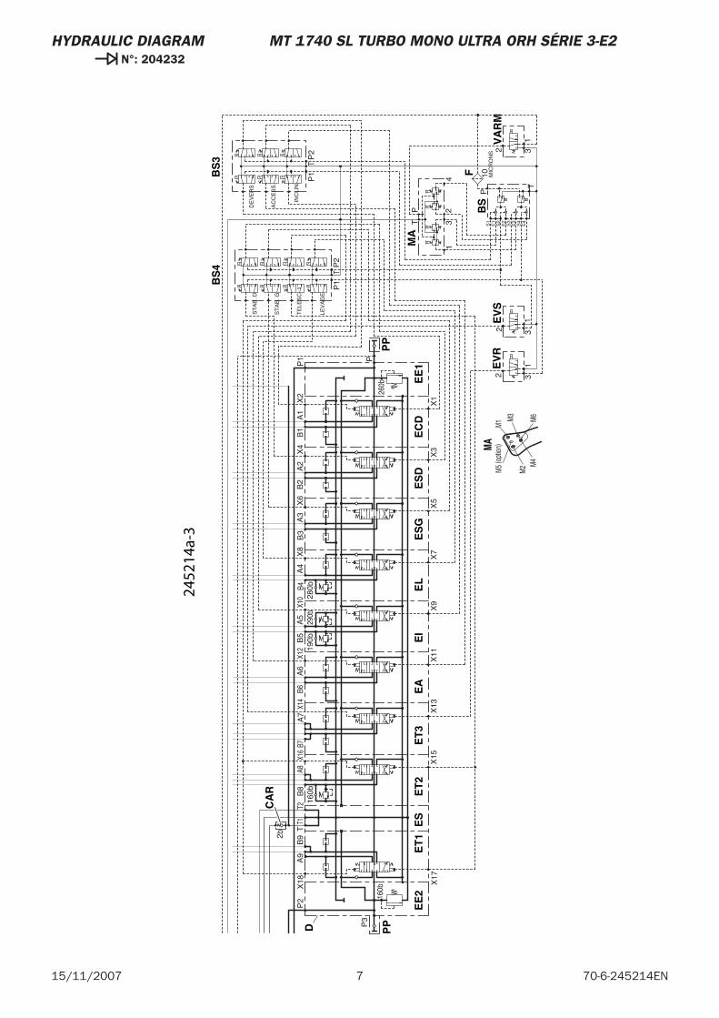
7 70-6-245214EN15/11/2007
HYDRAULIC DIAGRAM MT 1740 SL TURBO MONO ULTRA ORH SÉRIE 3-E2 N°: 204232
M3
M4
M6
M5
(opt
ion)
M1
M2
PP
EE
2E
T1
ES
D
EA
ET
3E
IE
SG
EL
ES
DE
E1
PP
EC
DM
A
BS
4B
S3
ET
2
EV
RE
VS
BS
F
VA
RM
CA
R
MA
2b
P3
P2
A9
T1T
T2B6
A6
B5
190b
A5
B4A
429
0bB
328
0bA
3B
2A
2
P
P1
A1
B1
B7A
7X
2X
4X
6X
8X1
0X1
2X1
4X
18
X13
X17
X11
X9
X7
X5
X3
X1
43
21
PT
TP
2P
1
P1
P2
T
ST
AB
. D
ST
AB
. G
TE
LES
C. 1
LEV
AG
E
DE
VE
RS
AC
CE
SS
.
INC
LIN
.
X15
B8
160b
X16
A8
31
2
31
2
160b
260b
B9
E2
E4
S4
E3
S3
T
S1
S2
E1
10 MIC
RO
NS
P
31
2
2452
14a-
3

8 15/11/200770-6-245214EN
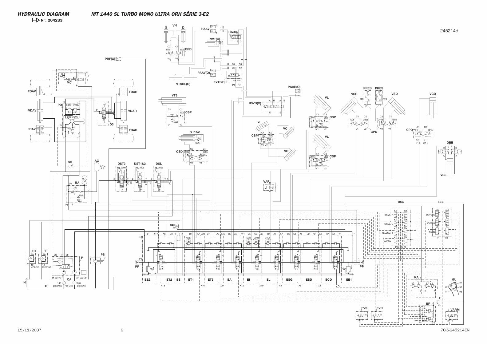
915/11/2007 70-6-245214EN
X16
X15
X4X6X8X10X12X18
X17 X13 X11 X9 X7 X5
X2
X3 X1
X14
MA
M2
M1
M6M4
M3
Ø1Ø1
10 μ
200b200b0,7 L.13 B.
0,7L.13B.
2b
41 cm3/tr41 cm3/tr
MICRONS10
2b
MICRONS10
2b EFLS P
T
LS
P
R L
32
P T
A
B1
100b
V1 V2
280b
V2
280bC1 C2 C2
V1
100bC1
V2
325bC2
V1
325bC1
P2 T
45±5b
35b
P1
U
43 21
PT
T P2P1
P1 P2T
STAB. D
STAB. G
TELESC. 1
LEVAGE
DEVERS
ACCESS.
INCLIN.
200b 200b
200 cm3/tr
140b
MICRONS140
100 L/mn
3 1
2
3 1
2
C2
V2
300bC1
V1
300b
V1 V2
C1200b
W
C2
C
K350b
V1 V2
C1200b
W
C2
C
K350b
P
A
T
B
P T B
A
P
BA
T
E2
E4
S4E3S3
T
S1
S2E1
P
3 1
2
200b
B
A A
B
V1 V2
C1 C2
200b
300b
45b 45b
100b
MICRONS140
350bC2 C1
350b
B
A
C2C1
V1 V2
A
32
1
A
32
1
32
1
P2P1
C4 C3
C2C1
V2 V1
E
BA BA
E
B7 A7 A7B8 B7 A2B2A3B3A4B4A5B5A6B6A8 B1 A1
1
2
315b110b
RLFB L N
P
ET1 ESDEL ESGEIEAESET2EE2
PP
ECD
PP
EE1ET3
PAAV
VAP
CSP
AC
PRESPRES
P
R
FR FR
FDAV
SC
VDAV
PD
FDAV
D3
FDAR
VDAR
FDAR
CSP
VL
VC
VL
VI
VC
VSG
CPD
VSD VCD
CPD
BA
MA
BS4 BS3
EVS EVR
CSD
CSP
PS
DSLDST3 DST1&2
BF
F
VARM
DBE
CAR
VBE
CSP
VT3
VT1&2
MC
R3V(O)
EVTF(O)
VVT(O)
PAAV(O)
VTSDL(O)
CPD
VNG D
R3VD(O)
PAAR(O)
P
180bD 280b280b190b
T2T T1P2
160b
P3
P1
260b
PRF(O)
CAN
245214d
HYDRAULIC DIAGRAM MT 1440 SL TURBO MONO ULTRA ORH SÉRIE 3-E2 N°: 204233

10 15/11/200770-6-245214EN

MT 1740 SL Turbo Ultra ORH RC Série 3-E2
15 / 11 / 2007
HYDRAULIC DIAGRAM
70-6-241704 EN

2 15/11/200770-6-241704EN
3 70-6-241704EN15/11/2007
-HYDRAULIC DIAGRAM
MT 1740 SL Turbo Ultra ORH RC Série 3-E2 Légende . . . . . . . . . . . . . . . . . 4
MT 1740 SL Turbo Ultra ORH RC Série 3-E2 N°: 206188. . . . . . . . . . . 5
MT 1740 SL Turbo Ultra ORH RC Série 3-E2 N°: 206189 . . . . . . . . . . . 7
CONTENTS
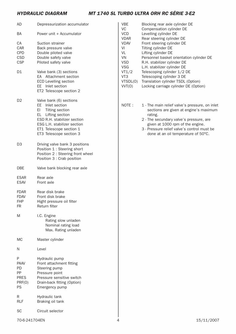
4 15/11/200770-6-241704EN
AD Depressurization accumulator
BA Power unit + Accumulator
CA Suction strainerCAR Back pressure valveCPD Double piloted valveCSD Double safety valveCSP Piloted safety valve
D1 Valve bank (3) sections EA Attachment section ECD Levelling section EE Inlet section ET2 Telescope section 2
D2 Valve bank (6) sections EE Inlet section EI Tilting section EL Lifting section ESD R.H. stabilizer section ESG L.H. stabilizer section ET1 Telescope section 1 ET3 Telescope section 3
D3 Driving valve bank 3 positions Position 1 : Steering short Position 2 : Steering front wheel Position 3 : Crab position
DBE Valve bank blocking rear axle
ESAR Rear axleESAV Front axle
FDAR Rear disk brakeFDAV Front disk brakeFHP Hight pressure oil fi lterFR Return fi lter
M I.C. Engine Rating slow unladen Nominal rating load Max. Rating unladen
MC Master cylinder
N Level
P Hydraulic pumpPAAV Front attachment fi ttingPD Steering pumpPP Pressure pointPRES Pressure sensitive switchPRF(O) Drain-back fi tting (Option)PS Emergency pump
R Hydraulic tankRLF Braking oil tank
SC Circuit selector
VBE Blocking rear axle cylinder DE VC Compensation cylinder DEVCD Levelling cylinder DEVDAR Rear steering cylinder DEVDAV Front steering cylinder DEVI Tilting cylinder DEVL Lifting cylinder DEVN Personnel basket orientation cylinder DEVSD R.H. stabilizer cylinder DEVSG L.H. stabilizer cylinder DEVT1/2 Telescoping cylinder 1/2 DEVT3 Telescoping cylinder 3 DEVTSDL(O) Translation cylinder TSDL (Option)VVT(O) Locking carriage cylinder DE (Option)
NOTE : 1 - The main relief valve’s pressure, on inlet
sections are given at engine’s maximum rating.
2 - The secundary valve’s pressure, are given at 1000 rpm of the engine.
3 - Pressure relief valve’s control must be done at an oil temperature of 50°C.
HYDRAULIC DIAGRAM MT 1740 SL TURBO ULTRA ORH RC SÉRIE 3-E2
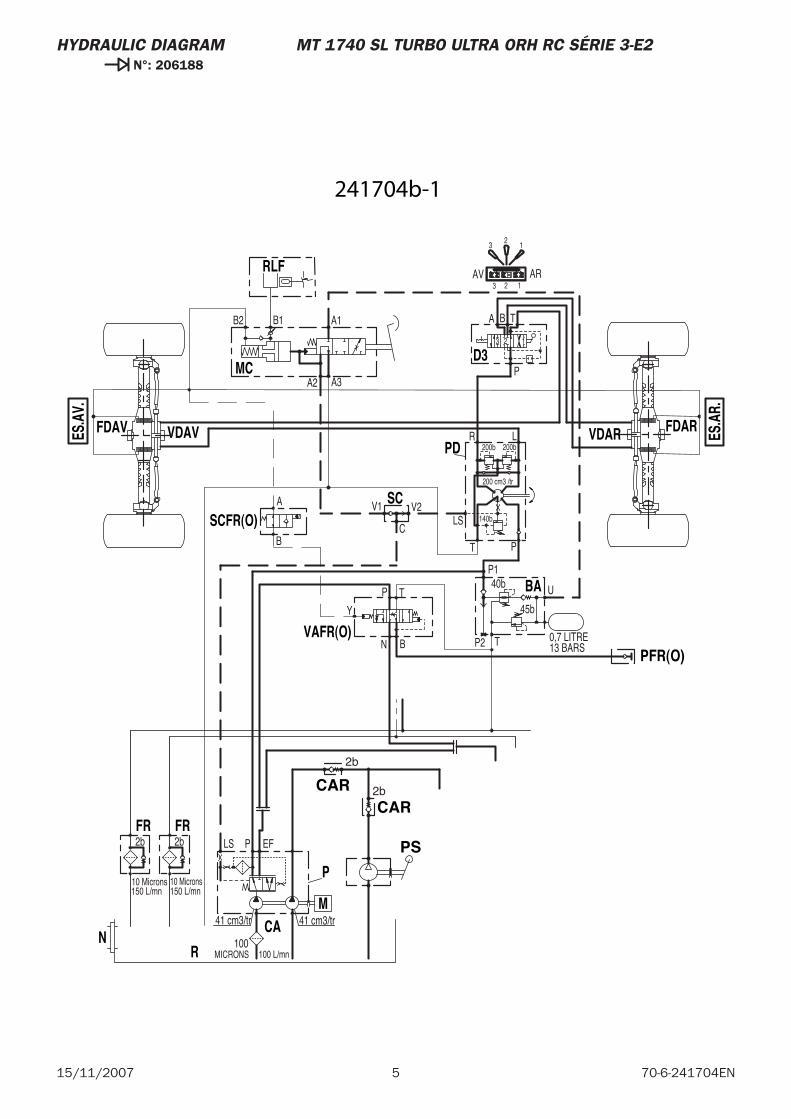
5 70-6-241704EN15/11/2007
HYDRAULIC DIAGRAM MT 1740 SL TURBO ULTRA ORH RC SÉRIE 3-E2 N°: 206188
13 BARS0,7 LITRE
U
P140b
45b
TP2
150 L/mn150 L/mn
41 cm3/tr41 cm3/tr
10 Microns
2b
10 Microns
2b EFLS P
MICRONS100
100 L/mn
200 cm3 /tr
140b
200b
BA T
123
P
LR
PT
LS
A1
A3A2
B2 B1
V2V1
200b
ARAV123
123
C
A
B
N
P T
B
PS
CAR
BA
NCA
P
R
FR FR
M
D3
PD
MC
RLF
SC
VDAVFDAVES.A
V.
VDAR ES.A
R.
FDAR
CAR
PFR(O)
VAFR(O)
SCFR(O)
2b
2b
Y
241704b-1
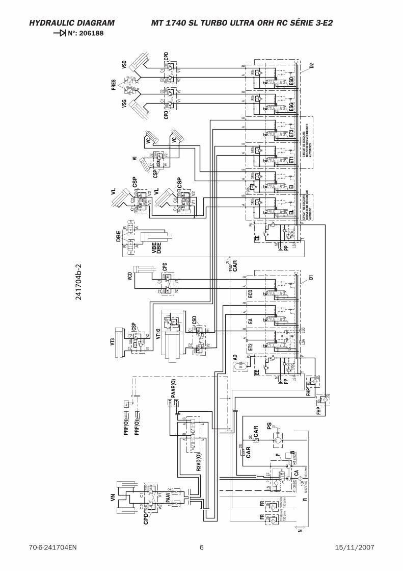
6 15/11/200770-6-241704EN
HYDRAULIC DIAGRAM MT 1740 SL TURBO ULTRA ORH RC SÉRIE 3-E2 N°: 206188
80b
80b
AB
BA
190b
280b
TP
M LS
Pp
260b
X
X
280b
TP
AB
LSB
LSAX
AB
M LS
BA
0.1
L
Pp
195b
X
X
X
160b
V1V2
100b
V1V228
0b
C1C2 30
0b
C1C2
150
L/m
n15
0 L/
mn
41 cm
3/tr
41 cm
3/tr
10 M
icron
s
2b
10 M
icron
s
2bEF
LSP
MIC
RONS10
010
0 L/
mn
100b
V1V228
0bC1
C2
BB
BA
AA
325b
V1V232
5bC1
C2
300b
200b
C2C1
V2V1
100b
32
1
300b
V1V2
C1C2
300b
BA
45b
45b
A
32 1
A
32 1
V1
V2
C1
200b
W
C2 CK
350b
BA
V1
V2
C1
200b
W
C2
K35
0bB
A
EAB
AB
E
6b
6b
20
20
PS
CA
R
DB
E
VB
E
ELEI
PP
EEEC
DET
2
PP
EA
AD
EE
FHP
ESD
ESG
ET1
N
CSP
VC
VI
VC
VSG
CPD
CA
P
R
FRFR
M
CPD
VSD
FHP
D2D1
CPD
VCD
CSP
VT1/
2
CSD
VT3
PRES
ET3
CA
R
CA
R
CIRC
UIT
DE S
ECO
URS
MO
UVEM
ENT
MÉC
ANIQ
UEAU
TORI
SE
CIRC
UIT
DE S
ECO
URS
MO
UVEM
ENTS
MÉC
ANIQ
UES
AUTO
RISE
S
DB
E
CS
P
VL
VL C
SP
CP
D
VN
PAAV
PAAR
(O)
R3VD
(O)
PRF(
O)
PRF(
O)
2b
B AAB
2b
2b
C
V2
350bC2
V1
C1
350b
12
2417
04b
-2
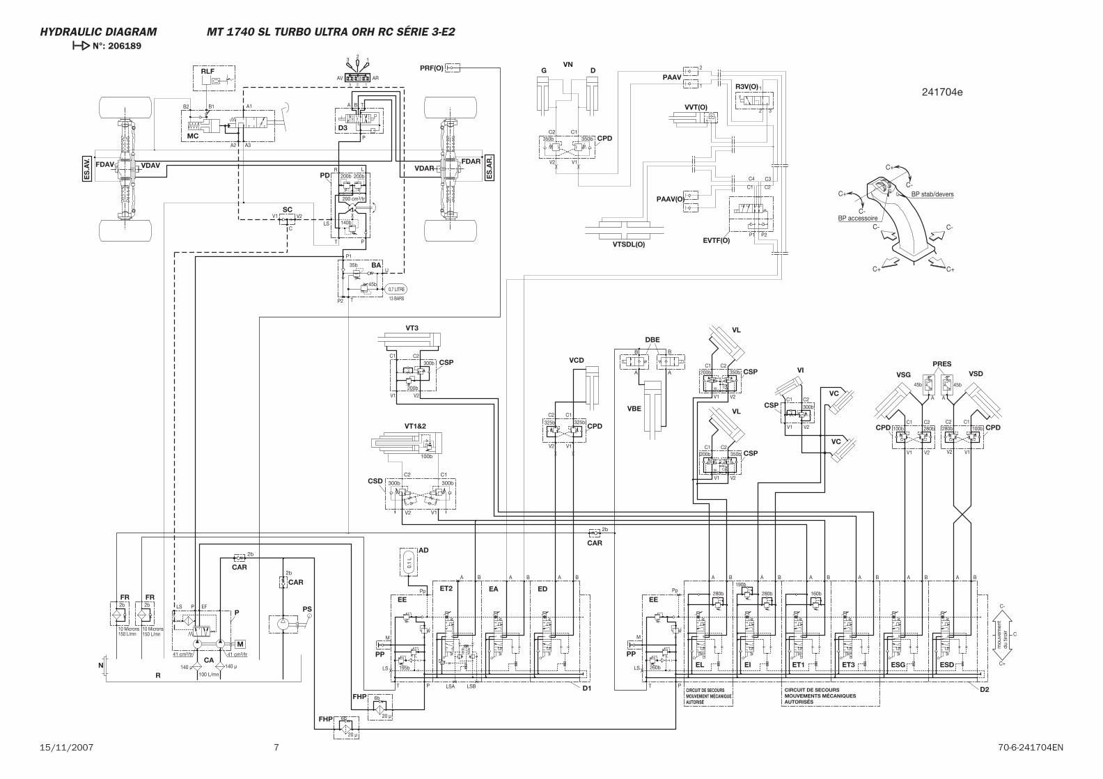
715/11/2007 70-6-241704EN
C+
C+ C+
C-
C-
C- C-
C+ BP stab/devers
BP accessoire
mou
vem
ent
du
tiroi
r
FDAR
PS
CAR
DBE
VBE
EL EI
PP
EE
EDET2
PP
EA
AD
EE
BA
FHP
ESDESGET1N
CSP
VC
VI
VC
VSG
CPD
CA
P
M
R
FR FR
D3
PD
MC
RLF
SC
VDAVFDAV VDAR
CPD
VSD
FHPD2D1
CPD
VCDCSP
VT3
PRES
ET3
CAR
CAR
CIRCUIT DE SECOURS MOUVEMENT MÉCANIQUE AUTORISÉ
CIRCUIT DE SECOURS MOUVEMENTS MÉCANIQUES AUTORISÉS
CSP
VL
VL
CSP
PAAV
CSD
VT1&2
PRF(O) DGVN
CPD
R3V(O)
VVT(O)
VTSDL(O)
PAAV(O)
EVTF(O)
160b
160b
A BBA190b
280b
T P
M
LS
Pp
260bX
X 280b
T P
A B
LSBLSA
X
A B
M
LS
BA
0.1
L
Pp
195bX
X X
13 BARS
0,7 LITRE
U
P1
35b
45b
TP2
160b
V1 V2 100b
V1 V2
280b
C1 C2300b
C1 C2
150 L/mn150 L/mn
41 cm3/tr41 cm3/tr
10 Microns
2b
10 Microns
2b EFLS P
140 μ100 L/mn
200 cm3/tr
140b
200b
BA T
123
P
LR
PT
LS
A1
A3A2
B2 B1
V2V1
200b
ARAV123
12
3
100b
V1V2
280bC1C2
C
B B BA A A
325b
V1V2
325bC1C2
300b
200b
C2C1
V2V1
BA
45b45b
A
3 2
1
A
3 2
1
V1 V2
C1200b
W
C2
C
K
350bB A
V1 V2
C1200b
W
C2
K
350bB A
140 μ
V1V2
1
2 3
C1 C2
C3C4
P1 P2
C+
C-
C
1
2
6b
6b 20 μ
350b
2b
B
A A
B
2b
2b
C
C2
V2
300b
C1
V1
300b
100b
350bC1C2
ES
.AV.
ES
.AR
.
20 μ
241704e
HYDRAULIC DIAGRAM MT 1740 SL TURBO ULTRA ORH RC SÉRIE 3-E2 N°: 206189

8 15/11/200770-6-241704EN