Embed Size (px)
Citation preview

Manitex Operation Manual

2 PN W450340A 07/13
Introduction The Greer Insight system is designed for use as an aid to crane operation. Do not use this system without a properly trained operator who is knowledgeable in safety guidelines, crane capacity information, and the crane manufacturer’s specifications. This manual describes the operation of the Greer Insight, hereinafter referred to as the system. Please read the contents and instructions contained
Table of Contents Outline of Operation ................................................................................................................. 4
System Components .......................................................................................................... 4 Power-Up Self-Test ................................................................................................................. 6 Home Display .......................................................................................................................... 6 The Configuration Display ........................................................................................................ 7
Home Button ...................................................................................................................... 8 Outrigger/Tire Selection ..................................................................................................... 8 Outrigger Position Sensing ................................................................................................ 8 Parts of Line ....................................................................................................................... 9 Jib Options ......................................................................................................................... 9 Pick Long, Pick Short, Pick Main ...................................................................................... 10 Stow (Stowed Jib) ............................................................................................................ 10 Winch ............................................................................................................................... 11 Operator Alarms ............................................................................................................... 11
The Home Display ................................................................................................................. 12 Outrigger/Tires ................................................................................................................. 12 Actual Load ...................................................................................................................... 13 Gauge Display ................................................................................................................. 14 Cancel Alarm Button ........................................................................................................ 14 Parts of Line ..................................................................................................................... 14 Information ....................................................................................................................... 15 Rated Capacity ................................................................................................................ 15 Calibration Button ............................................................................................................ 16 Erected Jib ....................................................................................................................... 16 System ............................................................................................................................. 16 Anti-Two-Block ................................................................................................................. 17 Jib Stowed ....................................................................................................................... 17 Boom Length Display ....................................................................................................... 17 Pick Points ....................................................................................................................... 18 Configuration Button ........................................................................................................ 18 Boom Length Symbol ....................................................................................................... 18 Boom Angle Symbol ........................................................................................................ 19 Load Radius Symbol ........................................................................................................ 19 Load Radius Display ........................................................................................................ 19 Backup Camera Button .................................................................................................... 20 Boom Angle Display ......................................................................................................... 20 Bar Graph ........................................................................................................................ 20

3 PN W450340A 07/13
Cancel Alarm Button .............................................................................................................. 21 Reset Function Kickout .................................................................................................... 21 System Bypass Switch ..................................................................................................... 22
Operator Programmable Alarms ............................................................................................ 23 Setting the Operator Alarms ............................................................................................. 23 Setting the Minimum/Maximum Boom Angle Alarms ........................................................ 24 Setting the Maximum Boom Length/Tip Height Alarms .................................................... 25

4 PN W450340A 07/13
OUTLINE OF OPERATION The system is an aid to crane operation. Crane functions are monitored by a variety of sensors.
The system compares the load suspended below the boom head to the crane capacity chart stored within the computer’s memory.
At approach to overload, the system sends audible and visual warning signals. The system can be configured to cause function kick-out by sending a signal to function disconnect solenoids.
System Components
• Display Unit • Computer Unit • Pressure Sensors • Reeling Drum Assembly, with Extension and Angle Sensors • Anti-Two-Block Switches • Cables • Audible Alarm • Installation/Operator Manuals
Display Unit The display unit provides the operator with:
• Rated Capacity • Actual Load • Bar graph representation of Actual Load vs. Rated Capacity • Radius of the Load • Boom Angle • Main Boom Length • Working Area • Crane Configuration
BOOM ANGLE SENSOR
The boom angle is measured by a potentiometer/pendulum assembly. It provides a voltage proportional to boom angle. This sensor is mounted inside the cable reeling drum assembly.
EXTENSION SENSOR
The extension sensor provides a voltage proportional to the extension of the boom. The extension sensor is mounted inside the cable reeling drum assembly.
5 PN W450340A 07/13
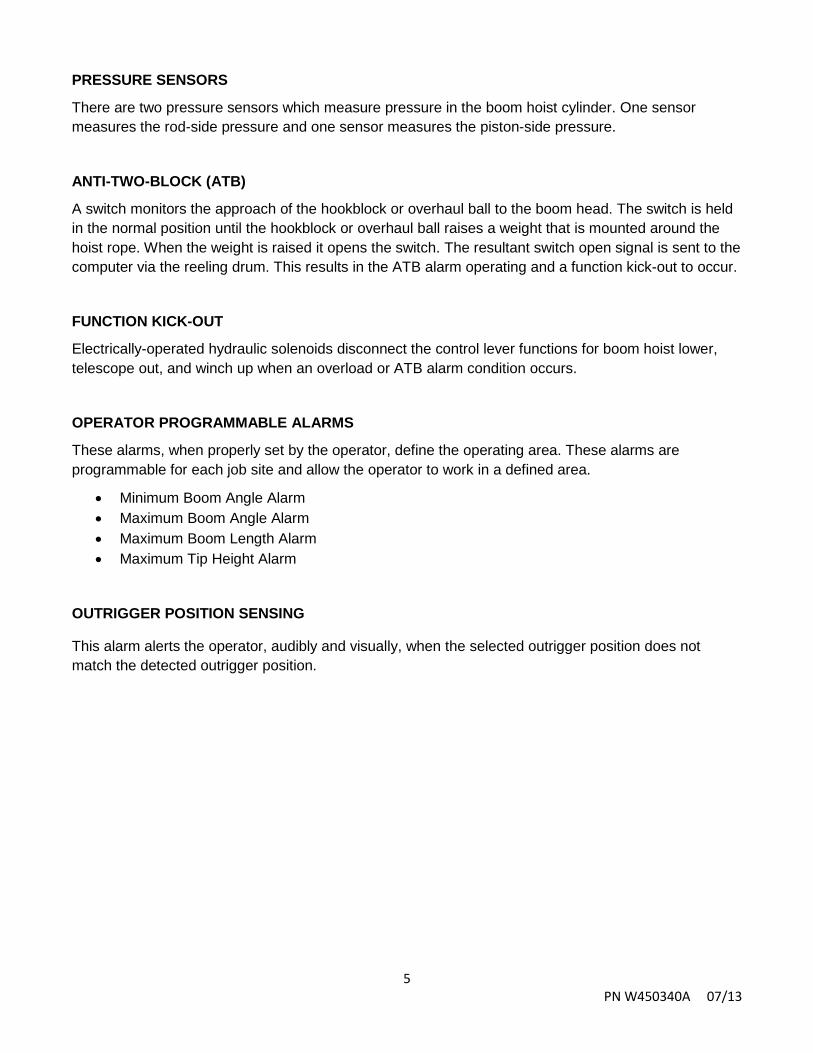
PRESSURE SENSORS
There are two pressure sensors which measure pressure in the boom hoist cylinder. One sensor measures the rod-side pressure and one sensor measures the piston-side pressure.
ANTI-TWO-BLOCK (ATB)
A switch monitors the approach of the hookblock or overhaul ball to the boom head. The switch is held in the normal position until the hookblock or overhaul ball raises a weight that is mounted around the hoist rope. When the weight is raised it opens the switch. The resultant switch open signal is sent to the computer via the reeling drum. This results in the ATB alarm operating and a function kick-out to occur.
FUNCTION KICK-OUT
Electrically-operated hydraulic solenoids disconnect the control lever functions for boom hoist lower, telescope out, and winch up when an overload or ATB alarm condition occurs.
OPERATOR PROGRAMMABLE ALARMS
These alarms, when properly set by the operator, define the operating area. These alarms are programmable for each job site and allow the operator to work in a defined area.
• Minimum Boom Angle Alarm • Maximum Boom Angle Alarm • Maximum Boom Length Alarm • Maximum Tip Height Alarm
OUTRIGGER POSITION SENSING
This alarm alerts the operator, audibly and visually, when the selected outrigger position does not match the detected outrigger position.

6 PN W450340A 07/13
POWER UP SELF-TEST Immediately following system power up, the system executes a system self-test which lasts for approximately 10 seconds. During this time the display shows the load chart number and units in use.
During this time, crane motions are disabled by the system function kick-out.
After the load chart screen, the display will automatically go to the home display.
HOME DISPLAY
It will be necessary to ensure the machine is correctly configured. Press the configuration button to access the configuration display from the home display.

7 PN W450340A 07/13
THE CONFIGURATION DISPLAY
NOTE: The graphic above is only a representation of the system. The shaded areas may vary in configuration depending on the application.
NOTE: Always check the point of lift and parts of line upon selection of the winch.
The configuration display gives a pictorial representation of the current system setup. Each shaded area contains one or more green indicators and a button to change the setup selection. In groups with multiple options, green indicators illuminate individually to indicate the selection. When the configuration is complete, press the home button to return to the main operation screen.
WARNING!!
THE DISPLAYED LOAD AND CAPACITY ARE BASED UPON THE CURRENT SELECTED POINT OF LIFT. NEITHER THE GREER INSIGHT SYSTEM, NOR THE CRANE CAPACITY CHART ALLOWS FOR LIFTING FROM MORE THAN ONE PICK POINT AT A TIME.
1
4
3
2
8
7
6
5
8 PN W450340A 07/13
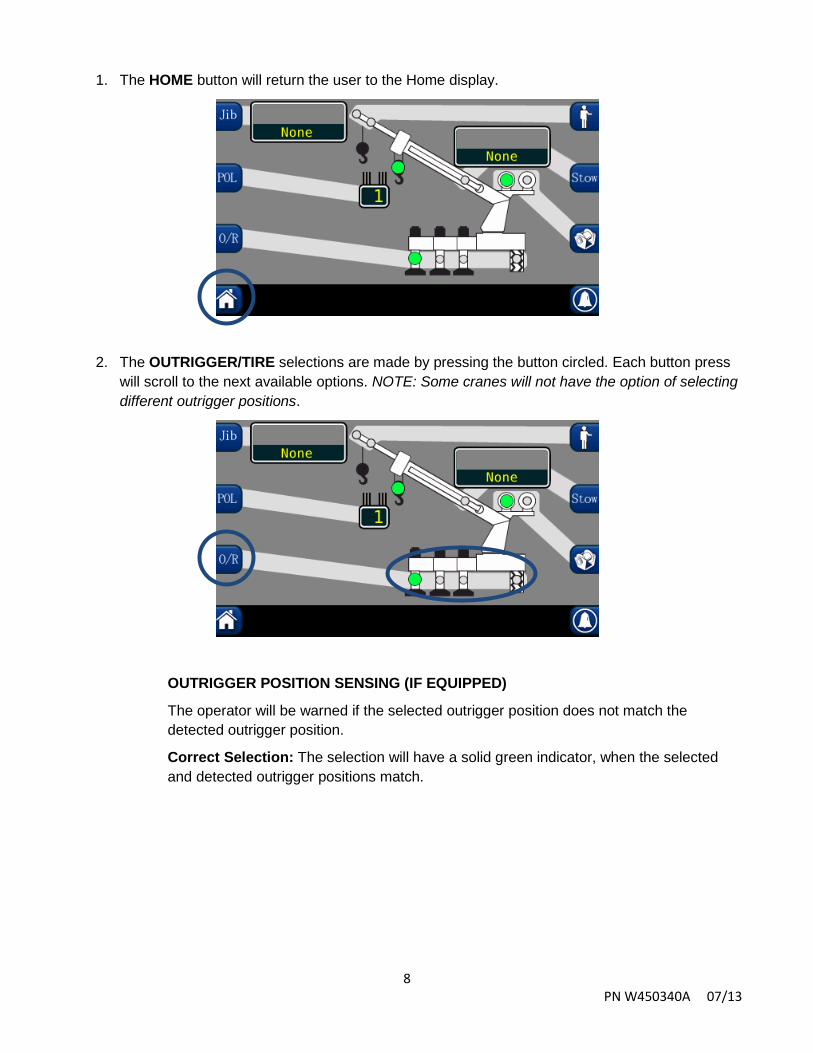
1. The HOME button will return the user to the Home display.
2. The OUTRIGGER/TIRE selections are made by pressing the button circled. Each button press will scroll to the next available options. NOTE: Some cranes will not have the option of selecting different outrigger positions.
OUTRIGGER POSITION SENSING (IF EQUIPPED)
The operator will be warned if the selected outrigger position does not match the detected outrigger position.
Correct Selection: The selection will have a solid green indicator, when the selected and detected outrigger positions match.

9 PN W450340A 07/13
Incorrect Selection: The base of the crane and outriggers will flash red and the text “OUTRIGGER ERROR” will flash on the screen. This will be accompanied by an audible alarm.
3. The (POL) button selects the current parts of line. Pressing the POL button will increment the
POL. When the maximum is reached, the indicator will rollover to one POL.
4. The JIB OPTIONS may be selected by pressing the jib button multiple times to scroll through the jib options. If a jib is not selected, or not available, the display will show “None”.

10 PN W450340A 07/13
5. The MAN button enables the optional upon platform.
6. The STOW (STOWED JIB), group contains one green indicator. This will illuminate when a jib is stowed on the boom. Each button press will scroll through the available jib options. If there are no options available, or none are selected, the display will show “None”.
11 PN W450340A 07/13
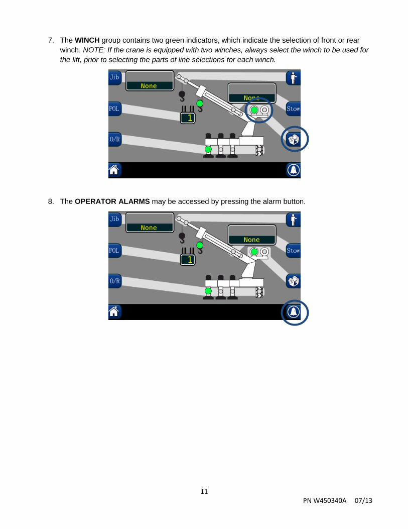
7. The WINCH group contains two green indicators, which indicate the selection of front or rear winch. NOTE: If the crane is equipped with two winches, always select the winch to be used for the lift, prior to selecting the parts of line selections for each winch.
8. The OPERATOR ALARMS may be accessed by pressing the alarm button.
12 PN W450340A 07/13
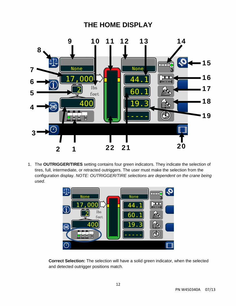
THE HOME DISPLAY
1. The OUTRIGGER/TIRES setting contains four green indicators. They indicate the selection of tires, full, intermediate, or retracted outriggers. The user must make the selection from the configuration display. NOTE: OUTRIGGER/TIRE selections are dependent on the crane being used.
Correct Selection: The selection will have a solid green indicator, when the selected and detected outrigger positions match.
1 2
4
5 6 7
9 10
11 12 13 14
15
16 17
18
19
21 22
8
3
20

13 PN W450340A 07/13
Incorrect Selection: The base of the crane and outriggers will flash red and the text “OUTRIGGER DISCREPANCY” will flash on the screen and an audible alarm. Access the Configuration Screen and make the correct outrigger selection.
2. The ACTUAL LOAD value displays the total load, including slings, etc., suspended below the lifting point.

14 PN W450340A 07/13
3. The GAUGE DISPLAY BUTTON is used to access the engine gauge screen. It provides information on engine RPM, volts, fuel level, oil pressure, and engine temperature.
4. The CANCEL ALARM BUTTON is used to silence the audible alarm generated by an overload, ATB Alarm, operator programmable alarm, or outrigger position mismatch. The audible alarm remains cancelled until the condition causing the alarm has been resolved.
5. The PARTS OF LINE display shows the amount of line chosen for the configuration selected. It is adjustable from the configuration screen.
15 PN W450340A 07/13
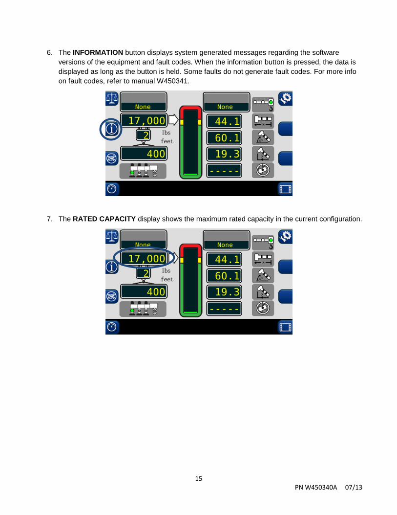
6. The INFORMATION button displays system generated messages regarding the software versions of the equipment and fault codes. When the information button is pressed, the data is displayed as long as the button is held. Some faults do not generate fault codes. For more info on fault codes, refer to manual W450341.
7. The RATED CAPACITY display shows the maximum rated capacity in the current configuration.

16 PN W450340A 07/13
8. The CALIBRATION BUTTON access the calibration menu.
9. The ERECTED JIB display shows the jib option selected for the machine. If there are no jib options available, or one is not selected, the display will show “None”.
10. The SYSTEM has the capability of showing metric or imperial units.
17 PN W450340A 07/13
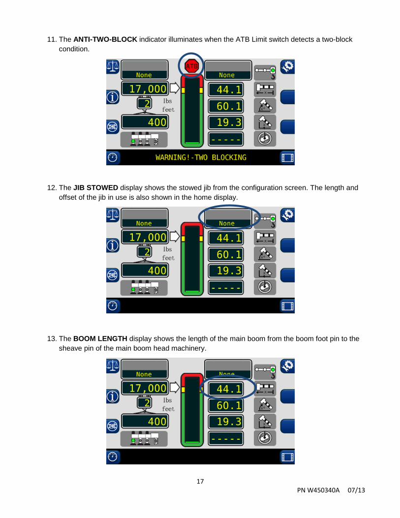
11. The ANTI-TWO-BLOCK indicator illuminates when the ATB Limit switch detects a two-block condition.
12. The JIB STOWED display shows the stowed jib from the configuration screen. The length and offset of the jib in use is also shown in the home display.
13. The BOOM LENGTH display shows the length of the main boom from the boom foot pin to the sheave pin of the main boom head machinery.
18 PN W450340A 07/13
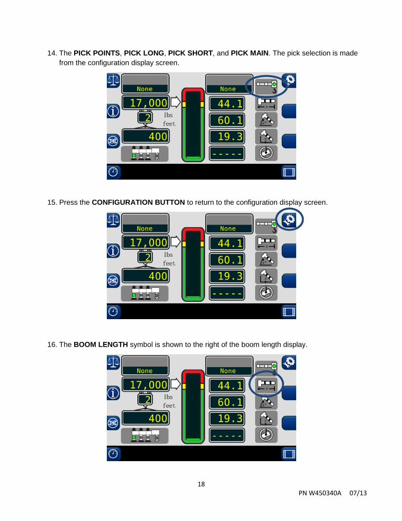
14. The PICK POINTS, PICK LONG, PICK SHORT, and PICK MAIN. The pick selection is made from the configuration display screen.
15. Press the CONFIGURATION BUTTON to return to the configuration display screen.
16. The BOOM LENGTH symbol is shown to the right of the boom length display.

19 PN W450340A 07/13
17. The BOOM ANGLE symbol is shown to the right of the boom angle display.
18. The LOAD RADIUS symbol is shown to the right of the load radius display.
19. The LOAD RADIUS display is shown to the left of the load radius symbol.
20 PN W450340A 07/13
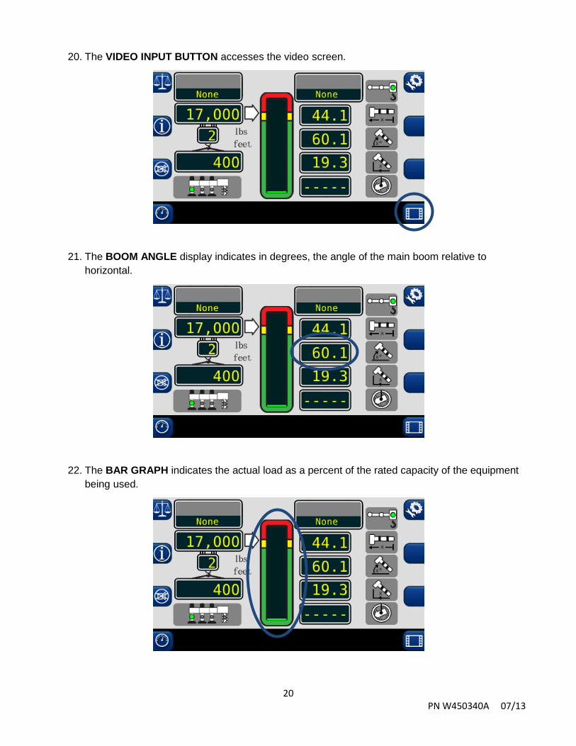
20. The VIDEO INPUT BUTTON accesses the video screen.
21. The BOOM ANGLE display indicates in degrees, the angle of the main boom relative to horizontal.
22. The BAR GRAPH indicates the actual load as a percent of the rated capacity of the equipment being used.
21 PN W450340A 07/13
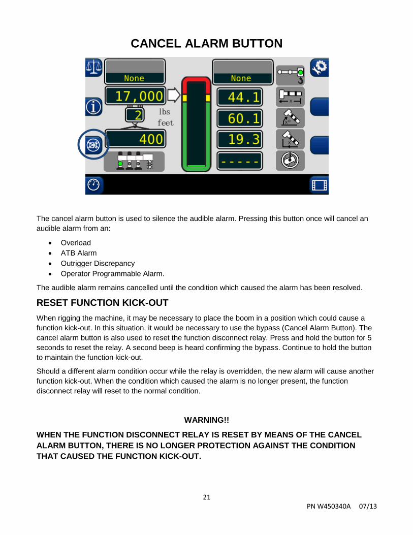
CANCEL ALARM BUTTON
The cancel alarm button is used to silence the audible alarm. Pressing this button once will cancel an audible alarm from an:
• Overload • ATB Alarm • Outrigger Discrepancy • Operator Programmable Alarm.
The audible alarm remains cancelled until the condition which caused the alarm has been resolved.
RESET FUNCTION KICK-OUT
When rigging the machine, it may be necessary to place the boom in a position which could cause a function kick-out. In this situation, it would be necessary to use the bypass (Cancel Alarm Button). The cancel alarm button is also used to reset the function disconnect relay. Press and hold the button for 5 seconds to reset the relay. A second beep is heard confirming the bypass. Continue to hold the button to maintain the function kick-out.
Should a different alarm condition occur while the relay is overridden, the new alarm will cause another function kick-out. When the condition which caused the alarm is no longer present, the function disconnect relay will reset to the normal condition.
WARNING!!
WHEN THE FUNCTION DISCONNECT RELAY IS RESET BY MEANS OF THE CANCEL ALARM BUTTON, THERE IS NO LONGER PROTECTION AGAINST THE CONDITION THAT CAUSED THE FUNCTION KICK-OUT.

22 PN W450340A 07/13
SYSTEM BYPASS SWITCH
During an FKO situation, use the System Bypass Switch to allow the crane to be moved out of the FKO condition. The screen will display this:

23 PN W450340A 07/13
OPERATOR PROGRAMMABLE ALARMS Setting the Operator Alarms
1. Press the configuration button to access the operator alarms from the main working screen. 2. Then press the operator alarm button. The information screen will show the current status of the
operator alarms.
Each button corresponds to the displayed alarm. These buttons operate as a toggle switch. If the alarm to be set is OFF, pressing the button will turn the alarm ON. If the alarm to be set is ON, pressing the button will turn the alarm OFF.
NOTE: Press the operator alarm button in order to cycle through the various user programmable alarms. Press the home button to return to the main screen. Exit at any time.
When operator alarms are set, the orange alarm will appear. An example below:
24 PN W450340A 07/13
OPERATOR PROGRAMMABLE ALARMS
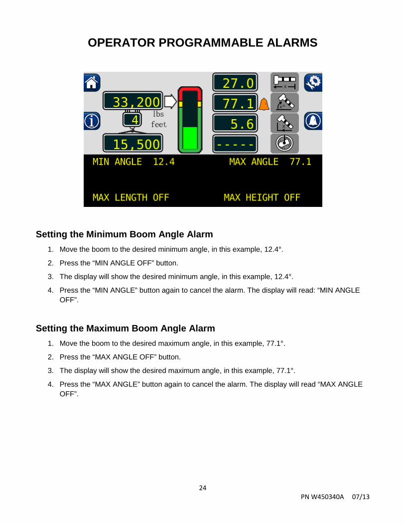
Setting the Minimum Boom Angle Alarm
1. Move the boom to the desired minimum angle, in this example, 12.4°.
2. Press the “MIN ANGLE OFF” button.
3. The display will show the desired minimum angle, in this example, 12.4°.
4. Press the “MIN ANGLE” button again to cancel the alarm. The display will read: “MIN ANGLE OFF”.
Setting the Maximum Boom Angle Alarm
1. Move the boom to the desired maximum angle, in this example, 77.1°.
2. Press the “MAX ANGLE OFF” button.
3. The display will show the desired maximum angle, in this example, 77.1°.
4. Press the “MAX ANGLE” button again to cancel the alarm. The display will read “MAX ANGLE OFF”.

25 PN W450340A 07/13
OPERATOR PROGRAMMABLE ALARMS
Setting the Maximum Boom Length Alarm 1. Move the boom to the desired maximum length, in this example, 58.8 ft.
2. Press the “MAX LENGTH OFF” button.
3. The display will show the desired maximum length, in this example, 58.8 ft.
4. Press the “MAX LENGTH” button again to cancel the alarm. The display will read “MAX LENGTH OFF”.
Setting the Maximum Tip Height Alarm 1. Move the boom to the desired maximum height, in this example 52.6 ft.
2. Press the “MAX HEIGHT OFF” button.
3. The display will show the desired maximum height, in this example 52.6 ft.
4. Press the “MAX HEIGHT” button again to cancel the alarm. The display will read “MAX HEIGHT OFF”.

26 PN W450340A 07/13
Consider Yourself Warned. ™ 11135 South James • Jenks, OK 74037
Phone: (918) 298-8300 Fax: (918) 298-8301
Greer Company is a part of TWG.
www.team-twg.com
As a leader in product innovation, Greer Company is committed to the ongoing improvement of its equipment. We reserve the right to make changes to our products without notice.
©2012 TWG. All rights reserved.