Embed Size (px)
Citation preview

Manifolds for domestic water systems
359 series
FunctionThe distribution manifolds with individual shut-off valves are used to control and distribute the medium in domestic water circuits. They are supplied already assembled in a plastic inspection box to facilitate positioning and installation. They are equipped with shut-off valves with a handwheel for each individual circuit and an identification number for the user served. Box installation can be completed using push-to-open inspection ports or aesthetic cover plates that are available in different finishes.
Product range
Code 359410 Distribution manifold with individual shut-off valves (4+3)
Code 359510 Distribution manifold with individual shut-off valves (5+4)
Code 359700 Recessed inspection port with push-to-open frameCode 359801 Plastic aesthetic cover plate (white)Code 359802 Stainless steel aesthetic cover plate (shiny finish)Code 359803 Stainless steel aesthetic cover plate (brushed finish)
003FM 21654
FunctionThe distribution manifolds with main shut-off valves are equipped with shut-off valves on the hot and cold inlets. They are also equipped with an outlet upstream of the shut-off valve which can be used for connection of the recirculation circuit. Box installation is completed using a finishing plate with hidden knobs.
Product range
Code 359420 Distribution manifold with main shut-off valves (4+3)Code 359902 Plate with concealed knobs (high chrome finish)
FunctionThe unit with main shut-off valves is only equipped with inlet valves. It allows maximum installation flexibility, as it is designed for connection of recirculation circuits and for the creation of various types of domestic water distribution. Box installation is completed using a finishing plate with hidden knobs.
Product range
Code 359100 Unit with main shut-off valvesCode 359902 Plate with concealed knobs (high chrome finish)
DISTRIBUTION MANIFOLDS WITH INDIVIDUAL SHUT-OFF VALVES
DISTRIBUTION MANIFOLDS WITH MAIN SHUT-OFF VALVES
UNIT WITH MAIN SHUT-OFF VALVES
01371/21 ENreplaces 01371/20 EN

Technical specifications
MaterialsManifold:- Body: - 359410 / 359510 / 359420 / 359100: brass EN 12165 CW617N - 359410 001 / 359510 001 / 359420 001 / 359100 001: “LOW LEAD” dezincification resistant alloy EN 12165 CW724R- Shut-off cartridge: PPSU- Seals: EPDM- Individual shut-off- knob: PA6G30- Brackets: PP
Box: ABS
PerformanceMedium: potable waterMaximum working pressure: 10 barWorking temperature range: 5-90 °CMain connections: adapter + fixing clipOutlet connections: adapter + fixing clipOutlet centre distance: 35 mmAverage internal diameter of the manifold: 15 mmIndividual shut-off valve Kv: 3,2 m3/hMain shut-off valve Kv: 7,0 m3/h
Coefficient of localized loss ξ through the outlet: 3(versions with main shut-off valves)
Dimensions
A
HM
L
C
G
I
I’
BD
FE
N
359410*359510*
270 190 80 57 47 86 82 35
82 35 27 1847
Code A B C D E F G H
I L M N O P
A
B
D
C
OHG I
270
359420*
190 80 58 52 80 29 50
32 66 83 34 27 19
N P
EF
L
M
A
B D
C
MH L NG I
EF
Code A B C D ECode A B C D E F G
H I L M N
190
359100*
190 80 58 49 82 29
50 87 34 27 19
Code A B C D E F G H
I I’ L M N Mass (kg)
Mass (kg)
Mass (kg)
359001*
A
B
CD
E
57 43 26 17 29
Mass (kg)
2.5 / 2.8 2.3
1.7
0.12
* versions in “LOW LEAD” dezincification resistant alloy code extension: 001

Italy normative references
UNI EN 806-3:2008: “Specifications for installations inside buildings conveying water for human consumption. Part 3: Pipe sizing - Simplified method”UNI 9182:2014: “Hot and cold water supply and distribution installations - Design, installation and testing”
Nominal sizing parameters
ApplianceFlow rate
(l/s)
Washbasin 0.1
Bidet 0.1
WC 0.1
Bathtub 0.4
Shower 0.2
Kitchen sink 0.2
Washing machine / domestic dishwasher
0.2
Sho
wer
Sho
wer
Sho
wer
Sho
wer
Sho
wer
Sho
wer
Maximum recommended velocities
(m/s)
Primary distribution, risers, floor distribution pipes
2
Supply line to individual user 4
Recirculation system 0.5–1
Pressure conditions (bar)
Static pressure at the drawing point
max. 5
Dynamic pressure at the drawing point
min. 1
Washbasin Ø 16x2Bidet Ø 16x2WC Ø 16x2Shower Ø 16x2
Calculation of the hot water volume:
Manifold with individual shut-off valves
Pin = Papp sf +ΔPd+ ΔPc + ΔPvis
Manifold with main shut-off valves
Pin = Papp sf +ΔPd+ ΔPc + ΔPvig+ ΔPder
ΔPc/der/c.T = ξ · ρ · v2/2/105 (bar)
ξ = local pressure drop coeff.
ρ = density (kg/m3)
v = velocity (m/s)
ΔPvis/vig = G2/Kv2 (bar)
G = flow rate (m3/h)
Kv = flow rate (m3/h) @ΔP (1 bar)
Case ADistribution manifolds with individual and main shut-off valves
Case BUnit with main shut-off valves
For a detailed calculation of the pressure drops within the loop circuit, please refer to the H. Cross method.This method applies to mesh systems; the iterative calculation leads to lower actual pressure drops (approx. 50 %) in relation to the simplified method.
AB Ø 16x2 BC Ø 16x2 CD Ø 16x2 DE Ø 16x2
Calculation of the hot water volume:
AB
C D E
Sizing exampleWhen the flow rates of the appliances are known, the pipe diameters can be sized. We suggest using multi-layer pipes. The length of pipes inside the room is used to calculate the volume of hot water contained within the pipes. If the water contained is greater than 3 l, a recirculation circuit must be provided.To guarantee the minimum pressure of 1 bar for the most disadvantaged appliance, the manifold/unit inlet pressure must be determined. It is therefore necessary to calculate the overall pressure drop. In the case in question, the most disadvantaged appliance is the shower.
Connection T loop
Internal Ø 12 mm 12 mm
Total L 8 m 16 m
Volume 0,9 l (< 3 l) 1,8 l (< 3 l)
Sho
wer
Sho
wer
Sho
wer
Pin = pressure at inletPapp sf. = disadvantaged appliance minimum pressureΔPd = distributed pressure dropΔPc = elbow local pressure dropΔPvis = individual shut-off valve local pressure dropΔPvig = main shut-off valve local pressure dropΔPder = outlet local pressure dropΔPc.T = T connection local pressure drop
Pin = Papp sf +ΔPd+ ΔPc + ΔPvig+ ΔPc.T + ΔPder
In-line distribution with T connection
Pass-through loop distribution
Internal Ø 12 mm
Total L 10 m
Volume 1,15 l (< 3 l)
Pin
Pin
Pin
Pin
ΔPd = r·L/ 105 (bar)
r = pressure drop per
unit of length (Pa/m)
L = length
of pipe (m)

Construction details
Patented anti-block cartridgeThe special patented cartridge designed for use in 359 series manifolds makes it possible to achieve a high level of operating reliability over time, thanks to the dual sealing gasket system. The materials used to make it offer a low operating torque during opening/closing procedures, and to minimise the blockage problems linked to the limescale typically present when ball valves are used. If necessary, the cartridge can be replaced simply by removing it from the front of the manifold and inserting the new one.
Types of fitting for pipe connection
Pipe connection is extremely easy and takes place by means of a fixing clip system.Two types of fitting are available: compression or press type.Compression fittings can only be used in inspectable boxes, while press fittings - given their securing method - can also be used in wall installations.
Fixing clip couplings
All connections to the manifold are performed by means of a fixing clip system. This offers optimal installation speed and impeccable seal reliability.
The special connection system does not allow installation errors. The fixing clip only fits into the corresponding groove if the element to be connected is in the correct position.
Dezincification resistant material with very low lead content (Low Lead)
359 series manifolds are also available in a version made using material with a very low lead content. This material is perfectly in line with the new regulatory provisions concerning contact with potable water. This is an innovative alloy with a very low lead content (< 0,1 %) and dezincification resistant properties.
Individual shut-off cartridge Main shut-off cartridge
PipePress �tting
Hose connection
Fixing clipsManifold
connection
There are two types of cartridge, one used in manifolds with individual shut-off valves and one designed for versions with main shut-off valves. The version used in main shut-off valves features a stem with a push-to-open system. It helps to achieve the concealed effect for the knobs used to move the cartridge.
PUSH-TO-OPEN SYSTEM(main shut-off version)
SIDE WALL SEALS
CARTRIDGE POSITIONING PROTRUSION
CONTROL STEM
O-RING
SEALING GASKET
Tee with fixing clip
The tee is an optional accessory capable of assuming different functions depending on the type of manifold/unit to which it is applied. In versions with individual shut-off valves, it can be used as an outlet for connection of the recirculation circuit, while in versions with main shut-off valves it allows an outlet to be added.

Function
The push-to-open inspection port offers easy inspection of the manifold with individual shut-off valves. When recessed into the wall, it blends perfectly with the wall in which it is installed.
Installation procedure for recessed inspection port with push-to-open frame
Aesthetic cover plate installation procedure
To install the cover plate, the support plate should be fixed to the box.
Fix the cover plate to the support plate.
DISTRIBUTION MANIFOLDS WITH INDIVIDUAL SHUT-OFF VALVES
Box installation procedure
The box can be installed on any type of wall (masonry, plasterboard, wood) using the relevant brackets provided. Once the box has been fitted on the wall, connect the pipes to the manifold using the special fixing clip couplings.
The protection cover protects the inner parts of the box during installation procedures.It also provides a reference for the area to which the superficial finish of the wall needs to be applied in order to achieve perfect alignment of the inspection port or cover plate.
Recessed inspection port with push-to-open frame Aesthetic cover plate
359700 Recessed inspection port with push-to-open frame Material: ABS
Plaster or tile the inspection port to achieve the same effect as used on the wall.
359801 Aesthetic cover plate, made of paintable plastic with a RAL 9010 white finish.Complete with support plate.
Aesthetic cover plate in stainless steel.Complete with support plate.
359802 shiny finish359803 brushed finish
Secure the inspection port frame to the box, adjusting its depth with the special adjustment screws until it is flush with the wall.
Function
The aesthetic cover plate is used to complete box installation, guaranteeing easy access for any necessary maintenance operations.
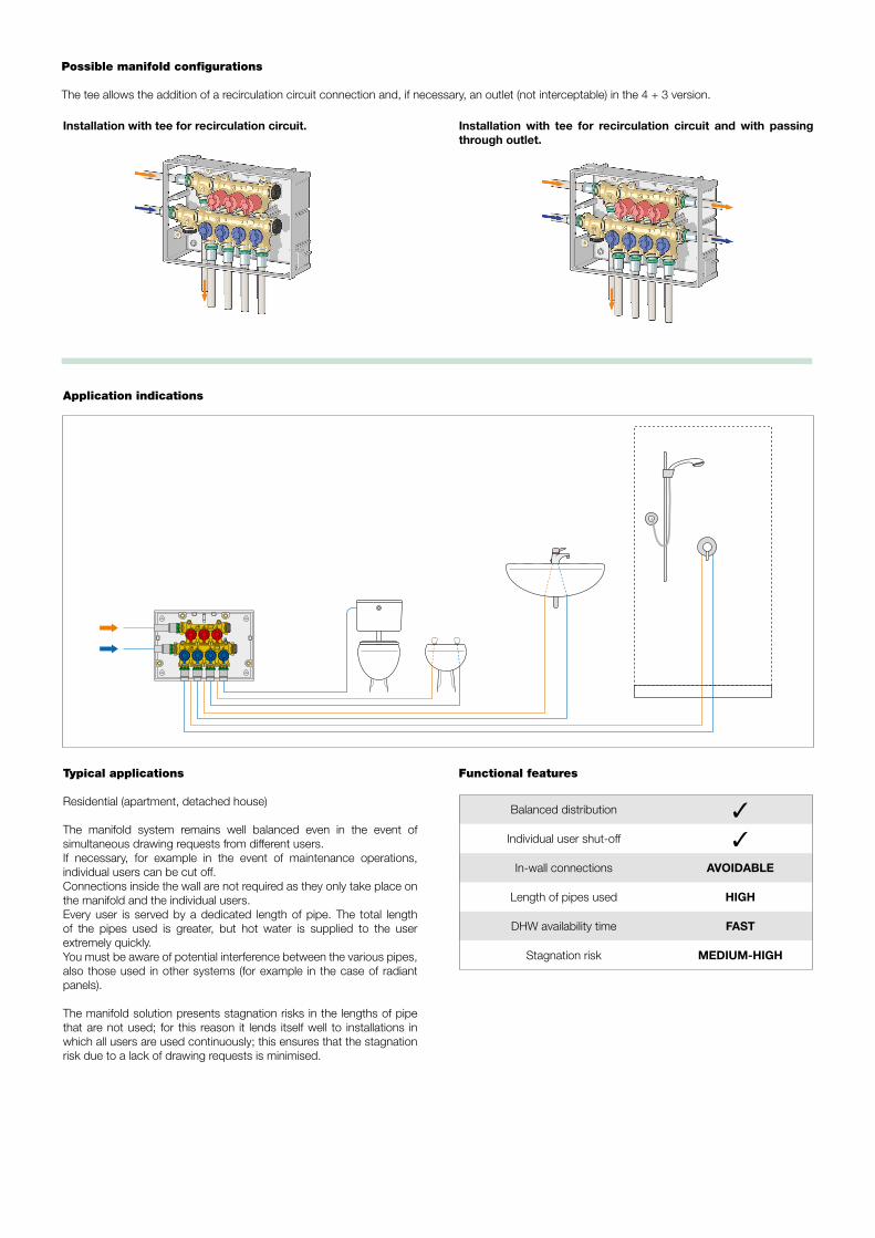
Possible manifold configurations
The tee allows the addition of a recirculation circuit connection and, if necessary, an outlet (not interceptable) in the 4 + 3 version.
Installation with tee for recirculation circuit. Installation with tee for recirculation circuit and with passing through outlet.
Application indications
Typical applications
Residential (apartment, detached house)
The manifold system remains well balanced even in the event of simultaneous drawing requests from different users.If necessary, for example in the event of maintenance operations, individual users can be cut off.Connections inside the wall are not required as they only take place on the manifold and the individual users.Every user is served by a dedicated length of pipe. The total length of the pipes used is greater, but hot water is supplied to the user extremely quickly.You must be aware of potential interference between the various pipes, also those used in other systems (for example in the case of radiant panels).
The manifold solution presents stagnation risks in the lengths of pipe that are not used; for this reason it lends itself well to installations in which all users are used continuously; this ensures that the stagnation risk due to a lack of drawing requests is minimised.
Balanced distribution ✓
Individual user shut-off ✓
In-wall connections AVOIDABLE
Length of pipes used HIGH
DHW availability time FAST
Stagnation risk MEDIUM-HIGH
Functional features

Code 359410 / 359510 / 359410 001 / 359510 001Domestic water distribution manifold, pre-assembled in a box with individual shut-off valves. Outlets 4 + 3 (or 5 + 4). Brass (or dezincification resistant alloy) body. PPSU shut-off cartridge. EPDM seals. PA6G30 knobs. PP brackets. ABS box. Medium potable water. Maximum working pressure 10 bar. Working temperature range 5-90 °C. Main connections and outlet connections adapter + fixing clip. Outlet centre distance 35 mm. Size 270 x 190 x 80 mm. Consists of: hot water manifold with shut-off valves, cold water manifold with shut-off valves, box for manifolds with supports for manifolds and mounting brackets, two end fitting caps with fixing clips, protection cover for installation.
Code 359700Recessed inspection port with push-to-open frame. ABS material. Useful size 255 x 175 x 62 mm.
Code 359801Aesthetic cover plate in paintable plastic with a RAL 9010 white finish. Complete with support plate.ABS material. Useful size 294 x 214 x 8 mm.
Code 359802 / 359803Stainless steel aesthetic cover plate (shiny or brushed finish). Complete with support plate.Useful size 294 x 214 x 8 mm.
SPECIFICATION SUMMARY
TMV
Application diagrams
Independent system: apartment (boiler with instantaneous production and no recirculation)
TMV
Independent system: multi-floor home (boiler with storage and recirculation)
Cold water
inlet
Cold water inlet

Finishing plate installation procedure
DISTRIBUTION MANIFOLDS WITH MAIN SHUT-OFF VALVES
Box installation procedure
359902 Plate with hidden knobs.Shiny chrome finish.
Replace the protection cover before plastering the wall. Use the adjustment screws to make sure the protective mask is flush with the finished wall.
Plaster the wall right up to the edges of the protective mask.
Remove the mask protecting the shut-off valves and use the built-in template to cut the stems, in order to achieve correct alignment of the knobs.
Secure the knobs using the relevant fixing screws and push on the chrome plated covers until they click into place.
Fit the finishing plate.
Press the knob to make it pop out and turn it to perform open/close procedures.
The special design allows installation in bathrooms, with an emphasis on design and functions.
The box can be installed on any type of wall (masonry, plasterboard, wood) using the relevant brackets provided. Once the box has been fitted on the wall, connect the pipes to the manifold using the special fixing clip couplings.
MaterialsFinishing plate: ABSKnobs: brass EN 12164 CW617N

Possible manifold configurations
The tee can be installed at the base of the manifold in the version with main shut-off valves, so that an additional outlet can be provided.The connection for the recirculation circuit is already built into the factory configuration.
Installation with side inlet and recirculation circuit towards the bottom.Tee for additional outlet and passing through outlet.
Installation with inlet at the bottom and side recirculation.Tee for additional outlet and passing through outlet.
Application indications
Typical applications
Residential (apartment, detached house)
The manifold system remains well balanced even in the event of simultaneous drawing requests from different users.If necessary, for example in the event of maintenance operations, the inlet at the bathroom can be cut off.Take extra care with the connections to the manifold, as they will be behind the wall in this configuration.Every user is served by a dedicated length of pipe. The total length of the pipes used is long, but hot water is supplied to the user extremely quickly.You must be aware of potential interference between the various pipes, also those used in other systems (for example in the case of radiant panels).
The manifold solution presents stagnation risks in the lengths of pipe that are not used; for this reason it lends itself well to installations in which all users are used continuously; this ensures that the stagnation risk due to a lack of drawing requests from one of the users is minimised.
Balanced distribution ✓
Individual user shut-off ✗
In-wall connections YES
Length of pipes used HIGH
DHW availability time FAST
Stagnation risk MEDIUM-HIGH
Functional features

Application diagrams
Floor distribution with recirculation at the manifold
Centralized system: residential apartment block (production with storage and recirculation circuit on the riser)
Code 359420 / 359420 001Domestic water distribution manifold, pre-assembled in a box with main shut-off valves. Outlets 4 + 3. Brass (or dezincification resistant alloy) body. PPSU shut-off cartridge. EPDM seals. PP brackets. ABS box. Medium potable water. Maximum working pressure 10 bar. Working temperature range 5-90 °C. Main connections and outlet connections adapter + fixing clip. Outlet centre distance 35 mm. Size 270 x 190 x 80 mm. Consists of: hot water manifold with main shut-off valve, cold water manifold with main shut-off valve, box for manifolds with supports for manifolds and mounting brackets, blank end fitting caps with fixing clips, closing cover.
Code 359902Plate with hidden knobs. Shiny chrome finish. Knob material chrome plated brass, finishing plate chrome plated ABS. Size 70 x 120 x 7 mm.
SPECIFICATION SUMMARY
EMV
EMV
Cold water inlet

Finishing plate installation procedure
UNIT WITH MAIN SHUT-OFF VALVES
Box installation procedure
The box can be installed on any type of wall (masonry, plasterboard, wood) using the relevant brackets provided. Once the box has been fitted on the wall, connect the pipes to the manifold using the special fixing clip couplings.
Replace the protection cover before plastering the wall. Use the adjustment screws to make sure the protective mask is flush with the finished wall.
Plaster the wall right up to the edges of the protective mask.
Remove the mask protecting the shut-off valves and use the built-in template to cut the stems, in order to achieve correct alignment of the knobs.
Secure the knobs using the relevant fixing screws and push on the chrome plated covers until they click into place.
Fit the finishing plate.
Press the knob to make it pop out and turn it to perform open/close procedures.
Possible unit configurations
Installation with horizontal pipes.
Installation with pipes from below.
L-shaped installation for recirculation circuit.
L-shaped installation with tee and through joint for hot and cold water recirculation circuit extension.

Typical applications
Residential (apartment, detached house) or comparable commercial applications
In distribution with outlets in T configuration, system balancing and the option of cutting off individual users is compromised, in order to achieve the most economical and straightforward installation.It is therefore necessary to take extra care if in-wall connections are present.Given the use of a shared pipe, the overall length of piping used is limited, while ensuring users are supplied with hot water quickly. The stagnation risk is only present in pipes running from the T to the user served, nevertheless the solution is suggested if there are users requesting hot water continuously that do not, therefore, create stagnation risks.
Balanced distribution ✗
Individual user shut-off ✗
In-wall connections YES
Length of pipes used LIMITED
DHW availability time FAST
Stagnation risk MEDIUM
Typical applications
Hotel or hospital, large systems with at-risk users.
The solution with pass-through loop maintains a well-balanced distribution as the water can reach individual users from two directions: from the pass-through line serving all users in series and from the loop closing off the circuit at the bottom. A dedicated pipe should actually be provided to close off the loop from the last user.The loop makes it possible to serve all users quickly, and especially to generate the movement of water throughout the whole circuit every time a drawing request is made. This reduces the risk of stagnation caused by non-continuous drawing; a typical use would be in hotel or hospital complexes.
Balanced distribution ✓
Individual user shut-off ✗
In-wall connections YES
Length of pipes used HIGH
DHW availability time FAST
Stagnation risk LOW
Distribution with outlets in T configuration
Pass-through loop distribution
Functional features
Functional features
Pass-through connection
T connection

Typical applications
Hotel or hospital with high level of automation, large systems with at-risk users.
This solution lends itself to use in structures with users that may be used non-continuously or where there may be long periods of disuse caused by unoccupied rooms. The flushing station (or electronic cock) generates controlled flows to guarantee the movement of hot and/or cold water according to a schedule or every time the passage of water is not detected for a specific period. The cold water recirculation circuit is used to keep the temperature at a controlled value.
Balanced distribution ✗
Individual user shut-off ✗
In-wall connections YES
Length of pipes used MEDIA
DHW availability time MEDIUM
Stagnation risk ABSENT
Pass-through distribution with flushing point
Application diagrams
Pass-through loop distribution and bathroom recirculation
Distribution with outlets in T configuration and floor recirculation
Functional features
Pass-through connection
Hot and cold water recirculation
Flushing station
Electronic cock

Cold wate chillerr
Verso locali ristoro e di servizio
EMVGeneratore
Ingresso fredda
Accumulo
EMV
Centralized system: hotel / hospital with a high level of automation (production with storage and peripheral hot/cold recirculation circuit)
Code 359100 / 359100 001Unit with main shut-off valves. Brass (or dezincification resistant alloy) body. PPSU shut-off cartridge. EPDM seals. PP brackets. ABS box. Medium potable water. Maximum working pressure 10 bar. Working temperature range 5-90 °C. Main connections and outlet connections adapter + fixing clip. Size 190 x 190 x 80 mm. Consists of: valve assembly, box for manifolds with supports for manifolds and fixing brackets, blank end fitting caps with fixing clips, closing cover.
Code 359902Plate with hidden knobs. Shiny chrome finish. Knob material chrome plated brass, finishing plate chrome plated ABS. Size 70 x 120 x 7 mm.
SPECIFICATION SUMMARY
Cold water inlet
To catering and service areas

359Multi-grip press fittingsfor multi-layer pipes with fixing clip.Dezincification resistant “LOW LEAD” alloy body .Max. working pressure: 10 bar.Working temperature range: 5–90 °C.
Can be used with clamps with profile H - TH - U.
PRESS FITTINGS FOR 359 SERIES MANIFOLDS
679002679006679009
Code
Calibrator Ø 16x2Calibrator Ø 20x2Grip for calibrator
679Gauge and grip for calibrating multi-layer pipes before use with series 359 fittings.
PipePress �tting
Hose connection
Fixing clipsManifold
connection
Calibration of the multi-layer pipe and assembly of the 359 series fitting
359024359064
Code
Ø 16x2Ø 20x2 After calibrating the pipe using
the relevant calibrator, push the pipe onto the fitting, making sure it reaches the end point.You should look through the windows to make sure the pipe is in the correct position.
Clamp the pipe using the relevant clamp, until a click sounds automatically.
Insert the pipe, including the fitting, into the slot on the manifold.
Secure it with the dedicated fixing clip.
TH-profile clamp U-profile clamp H-profile clamp
Code 359024 / 359064Multi-grip press fittings for multi-layer pipes with fixing clip. Size Ø 16x2 (or Ø 20x2). Dezincification resistant alloy body. Maximum working pressure 10 bar. Working temperature range 5-90 °C. Can be used with clamps with profile H - TH - U.
SPECIFICATION SUMMARY

Caleffi S.p.A.S.R. 229 n. 25 · 28010 Fontaneto d’Agogna (NO) · ItalyTel. +39 0322 8491 · Fax +39 0322 [email protected] · www.caleffi.com© Copyright 2021 Caleffi
We reserve the right to make changes and improvements to our products and the related technical data in this publication, at any time and without prior notice.The website www.caleffi.com always has the most up-to-date version of the document, which should be used for technical verifications.
ACCESSORIES FOR 359 SERIES MANIFOLDS
SPARE PARTS FOR 359 SERIES MANIFOLDS
* “LOW LEAD” dezincification resistant alloy available on request with code extension: 001
359Tee with fixing clip.Brass body.Max. working pressure: 10 bar.Working temperature range: 5–90 °C.
359Adapter with fixing clip.Dezincification resistant “LOW LEAD” alloy body .Max. working pressure: 10 bar.Working temperature range: 5–90 °C.
359Blank cap with fixing clip.Composite body.
359Manifold with individual shut-off valves (blue knobs).
Individual shut-off cartridge.
359Manifold with individual shut-off valves (red knobs).
Main shut-off cartridge.
359Manifold with main shut-off valve.
359Spare protection cover.
359Unit with main shut-off valve. 359
Box back panel.
359 Fixing clip.
Code
359003 23 p.1,5
359004 1/2” flat seat Ø 13
359005 3/4” flat seat Ø 18
359006 3/4” Euroconus Ø 18
Code
359001*
Code
359002
CodeNo. of outlets
359240* 4
359250* 5
CodeNo. of outlets
359330* 3
359340* 4
CodeNo. of outlets
359630* 3359640* 4
Code
359101*
Code
359007
Code
F0001305
Code
F0001306
Code
359010
CodeNo. of outlets
359011 spare back panel for 3+4 individual shut-off valves
359012 spare back panel for 4+5 individual shut-off valves
359013 spare back panel for 3+4 main shut-off valves
359014 spare back panel for main shut-off valves
* Body in “LOW LEAD” dezincification resistant alloy available on request with code extension 001.