Embed Size (px)
Citation preview
Manhole Form Hire
Equipment assembly and
handling guide
General instructions
Form assembly
Fitting extensions to elongate
Pit box assembly
Scaffold assembly
In-situ manhole casting forms
When ordering, consider all deliveries as “next day”. To
guarantee items are available on site early, order for the
previous day. We welcome your own pick up and return.
Do not hit with steel hammers.
Use wood or similar to baffle impact.
Apply form release oil before each
pour.
Clean after use.
Dismantle and stack in safe
place for collection.
Penalties apply for damage, missing
bolts, not cleaned or not split for
collection.
Assembly & Dismantling Guidelines
It is recommended that a minimum two people undertake the process
It is recommended that all assembly and dismantling is conducted on flat ground.
Relevant PPE is site specific.
You will need lifting chains and lifting apparatus, 2 x 21mm socket spanners (or similar) and
screwdriver (or similar).
Important information before commencing.
Each drum has a unique identification and should not be mixed up with other similar forms.
Eg. 150015NC 1-6
1500 = Ø, 15 = 1.5 mt height, N represents an Inner (T = outer), C = Set C in alphabetical
sequence, 1-6 = no. of panels.
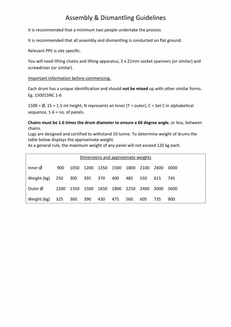
Chains must be 1.6 times the drum diameter to ensure a 60 degree angle, or less, between chains. Lugs are designed and certified to withstand 10 tonne. To determine weight of drums the table below displays the approximate weight. As a general rule, the maximum weight of any panel will not exceed 120 kg each.
Dimensions and approximate weights
Inner Ø 900 1050 1200 1350 1500 1800 2100 2400 3000
Weight (kg) 250 300 395 370 400 485 550 615 745
Outer Ø 1200 1350 1500 1650 1800 2250 2400 3000 3600
Weight (kg) 325 360 390 430 475 560 605 735 900
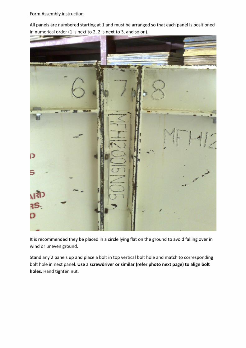
Form Assembly instruction
All panels are numbered starting at 1 and must be arranged so that each panel is positioned
in numerical order (1 is next to 2, 2 is next to 3, and so on).
It is recommended they be placed in a circle lying flat on the ground to avoid falling over in
wind or uneven ground.
Stand any 2 panels up and place a bolt in top vertical bolt hole and match to corresponding
bolt hole in next panel. Use a screwdriver or similar (refer photo next page) to align bolt
holes. Hand tighten nut.
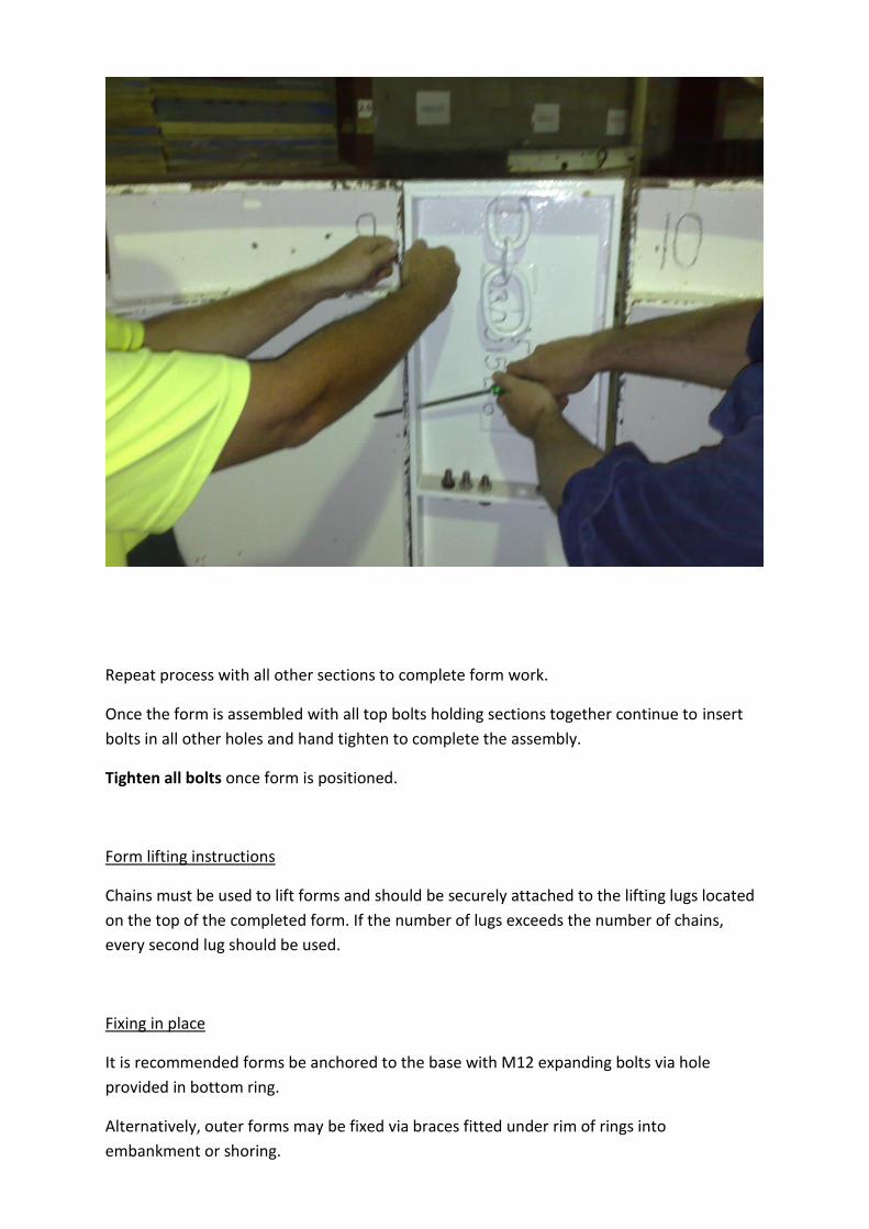
Repeat process with all other sections to complete form work.
Once the form is assembled with all top bolts holding sections together continue to insert
bolts in all other holes and hand tighten to complete the assembly.
Tighten all bolts once form is positioned.
Form lifting instructions
Chains must be used to lift forms and should be securely attached to the lifting lugs located
on the top of the completed form. If the number of lugs exceeds the number of chains,
every second lug should be used.
Fixing in place
It is recommended forms be anchored to the base with M12 expanding bolts via hole
provided in bottom ring.
Alternatively, outer forms may be fixed via braces fitted under rim of rings into
embankment or shoring.
Stacking of Forms.
Place bottom drum into position ensuring all bolts are hand tight.
Lift another drum of the same diameter on top ensuring like numbered panels line up
vertically.
Use extra bolts to fasten forms together in bolt holes located on the top and bottom joining
rings. Screwdriver or similar may be used to manoeuvre forms so that bolt holes line up.
Lastly, tighten all bolts.
Dismantling Inner Forms.
Remove bolts from only one drum at a time. Remove all bolts except top bolts.
Attach chain to lug of panel next to any key. Remove key by breaking concrete bond by
inserting trowel or similar between concrete and key and levering. A hammer blow may be
used however you must baffle the impact with wood or similar. Tension may be placed on
chain in an inwards direction, not more than 45 degrees ensuring a minimum of free swing.
Next, remove remaining bolt from panel secured by chain. Repeat process above.
Continue until all panels are removed.
Immediately remove any excess concrete, stack all panels out of harm’s way.
Dismantling Outer Forms.
Same as inner forms however, there are no keys.
Outer forms fall away from wall so that chain tension should be in the outer direction.
Forms must be returned in the same condition you got them
as cleaning and repair charges apply.
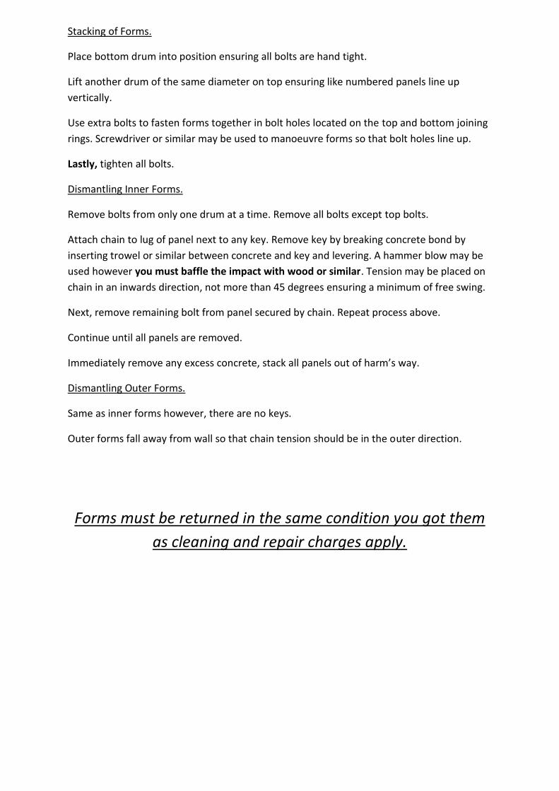
Fitting extension panels to elongate.
When splitting drums to elongate, care must be taken to halve in the correct place. Inner drums
have 2 keys or stripper bars. They are designed with angled sides so that they can collapse inwards
and provide room for the other panels to be removed. Extension panels must be bolted to “square”
edges, not angled so do not split drum at keys. Always assemble forms in numerical order. Refer to
diagram and photo.
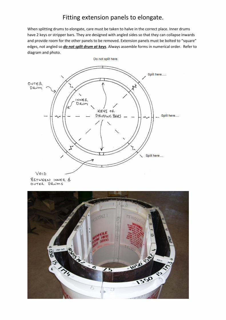
Pit box assembly
Loosen Z nuts so that clamping plate is
removed far enough from corner to allow the
placement of panels.
Hand tighten all 3 Z nuts.
Repeat for the other corners. This is best done
standing inside the box.
With the box loosely assembled, tighten Z
nuts with hammer, ensuring all the while that
the rebate on the shutter aligns with the steel
corner.
Using the braces supplied put in position and
wind out until they are firm against the inside
of the pit.
External corners have locating pins that align
with their respective shutters.
We recommend external shutters be propped
into the surrounding earth to prevent bowing.
Scaffold assembly guidelines
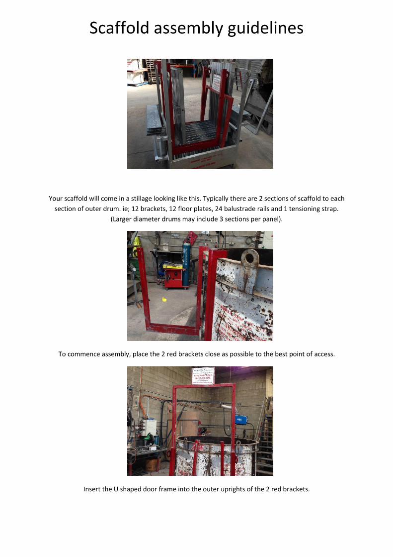
Your scaffold will come in a stillage looking like this. Typically there are 2 sections of scaffold to each
section of outer drum. ie; 12 brackets, 12 floor plates, 24 balustrade rails and 1 tensioning strap.
(Larger diameter drums may include 3 sections per panel).
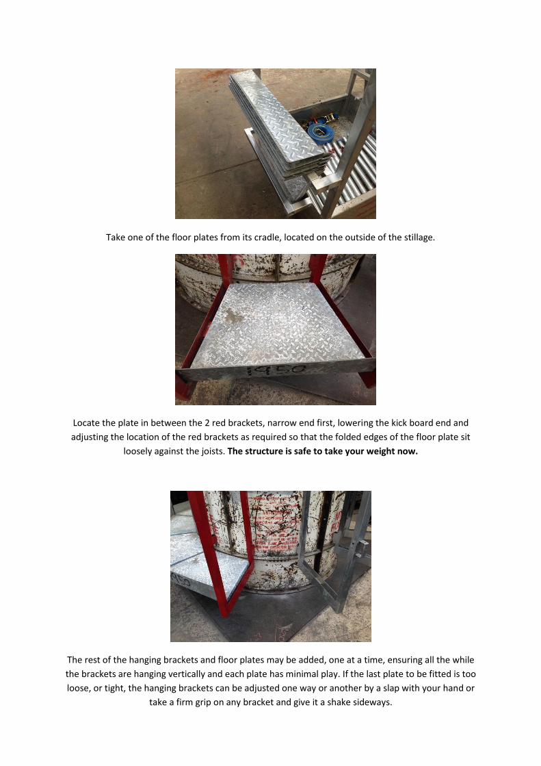
To commence assembly, place the 2 red brackets close as possible to the best point of access.
Insert the U shaped door frame into the outer uprights of the 2 red brackets.
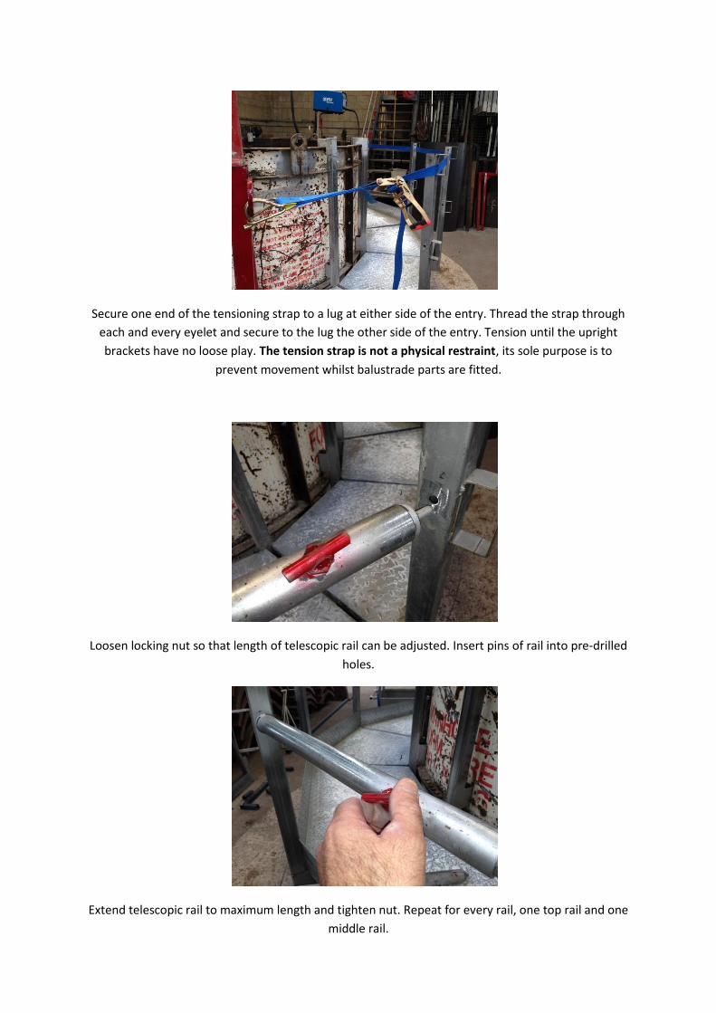
Take one of the floor plates from its cradle, located on the outside of the stillage.
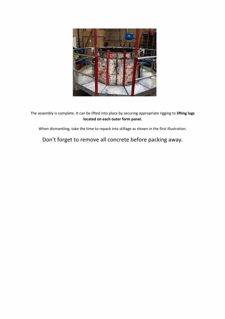
Locate the plate in between the 2 red brackets, narrow end first, lowering the kick board end and
adjusting the location of the red brackets as required so that the folded edges of the floor plate sit
loosely against the joists. The structure is safe to take your weight now.
The rest of the hanging brackets and floor plates may be added, one at a time, ensuring all the while
the brackets are hanging vertically and each plate has minimal play. If the last plate to be fitted is too
loose, or tight, the hanging brackets can be adjusted one way or another by a slap with your hand or
take a firm grip on any bracket and give it a shake sideways.
Secure one end of the tensioning strap to a lug at either side of the entry. Thread the strap through
each and every eyelet and secure to the lug the other side of the entry. Tension until the upright
brackets have no loose play. The tension strap is not a physical restraint, its sole purpose is to
prevent movement whilst balustrade parts are fitted.
Loosen locking nut so that length of telescopic rail can be adjusted. Insert pins of rail into pre-drilled
holes.
Extend telescopic rail to maximum length and tighten nut. Repeat for every rail, one top rail and one
middle rail.
The assembly is complete. It can be lifted into place by securing appropriate rigging to lifting lugs
located on each outer form panel.
When dismantling, take the time to repack into stillage as shown in the first illustration.
Don’t forget to remove all concrete before packing away.