Embed Size (px)
Citation preview

MANAK BHAVAN, 9 BAHADUR SHAH ZAFAR MARG, NEW DELHI 110002
Phone: + 91 11 23230131, 23233375, 23239402 Extn 4402; Fax: + 91 11 23235529
व्याeपक पयपक चालe मयौद e
हमारा संदर्भ : सीईडी 46/ टी-11 यययय यययययय 07 अक्टूबर 5102 तकनीकी सममतत :राष्ट रीय र्वन तनमाभण संहहता ववषय सममतत, सीईडी 46
............................................................................................................................................................ प्रeप्य.प.e य: 1 सदवि यइंजीनमााीयविभeगयपक चाषद्यपेयदभीयद स्या
2ययाeष्टयरीायभिमयनमौe हयदं व.eयविषायदसौन.,यदीईडीय46यिय 46:P9 पेयदभीयद स्या
3 रूचलयाखमेयिe ेयअन्यायनमपeाय
ौवो ा/ौवो ाe,
नमम्यमस िख.यौद eयद ं्यमयव :
प्र ेखयदंख्याe शीष प
सीईडी 46 (8141)WC राष्ट रीय र्वन तनमाभण संहहता का मसौदा: र्ाग 6 संरचनात्मक डडजाइन,
अनरु्ाग 6 [ SP7(र्ाग6/ अनरु्ाग 6) का तीसरा पनुरीक्षण ]
पृपक ाeयइदयौद ेयपeयअि ोपमयपाेंयऔायअपक मीयदम्यौन.ा यंावयत.e.ेयवए यभेजेंयिपया यावयौद eयभeा.यप याeष्टयरीायभिमयनमौe हयदं व.eयपेयभeगयपेयरूपक यौेंयप्रपeसश.यवोय.ोयइदयपक ायअौ यपामेयौेंयआपक पेयव्यािदeायअविeयपeाोतeायौेंय्याeयप ामeइा यंआयदप.ीयव।य
दम्यौन.ा यंभेजमेयप यअनं.ौयन.चवय: 07 मिंता 2015 ा यपोईयदम्यौन.यवोय.ोयपृपक ाeयअोोवस्य.eक्षरीाीयपोयरपक चास िख.यपक .ेयपक ायद ं्यमयोोौमेट यौेंयभेजेंय यवोयदपेय.ोयपृपक ाeयअपक मीयदम्यौन.ा यं
ई-ौे यद्िeाeय[email protected]यपक ायभेजेंय
ा यपोईयदम्यौन.यप्रeप्य.यमवींयवो.ीयव यअविeयदम्यौन.यौेंयपेि यभeषeयदम्यतन्योीयरुटए यवएईय.ोयरपक ाो्य.यप्र ेख यपोयावeि.यअनं.ौयरूपक य ेय ाeयजe गeय या यदम्यौन.य.पमीप यप्रपृन.यप यवएईय.ोयविषायदसौन.पेयअ्याक्षरीयपेयपक ाeौश यदेयअविeयरमप यइच्याeयपक ायआगेयप यपeा िeवीयपेयस यविषायदसौन.यपोयभेजेयजeमेयपेयतe यप्र ेखयपोयअनं.ौयरूपक य ेय ाeयजe गeय
ावयप्र ेखयभeा.ीायौeमपयबयाूेाोयप यि तदeइ यwww.bis.org.in पक ायभीयरपक बयोयव य
ोन्यािe य
भि ीा,
यव0
य(ती.पे.यसदन्वe)
दं ्यम: रपक चास िख. प्रौएखय(सदवि यइंजीनमााी)
ोोम/ो ्यदय:य011-23235529

2
MANAK BHAVAN, 9 BAHADUR SHAH ZAFAR MARG, NEW DELHI 110002
Phone: + 91 11 23230131, 23233375, 23239402 Extn 4402; Fax: + 91 11 23235529
DOCUMENT DESPATCH ADVICE
TECHNICAL COMMITTEE:
NATIONAL BUILDING CODE SECTIONAL COMMITTEE, CED 46 ADDRESSED TO: 1. All Members of Civil Engineering Division Council, CEDC 2. All Members of National Building Code Sectional Committee, CED 46 and Panel for Steel, CED 46:P9 3. All other interests.
Dear Sir/Madam,
Please find enclosed the following draft:
Doc. No. Title
CED 46 (8041)WC Draft National Building Code of India: Part 6Structural Design, Section 6 Steel [Third Revision of SP 7(Part 6/Section 6)]
Kindly examine the draft and forward your views stating any difficulties which you are likely to experience in your
business or profession if this is finally adopted as Part of the National Building Code of India. Last Date for comments: 07 November 2015.
Comments if any, may please be made in the format as attached, and mailed to the undersigned at the above address. You are requested to send your comments preferably through e-mail to [email protected].
In case no comments are received or comments received are of editorial nature, you may kindly permit us to
presume your approval for the above document as finalized. However, in case of comments of technical nature are received then it may be finalized either in consultation with the Chairman, Sectional Committee or referred to the Sectional Committee for further necessary action if so desired by the Chairman, Sectional Committee.
This document is also hosted on BIS website www.bis.org.in.
Thanking you, Yours faithfully,
Sd/- (B. K. Sinha) Head (Civil Engg) Encl: as above
DRAFT IN WIDE CIRCULATION
Reference Date
CED 46/T-11 07 October 2015

3
FORMAT FOR SENDING COMMENTS ON THE DOCUMENT [Please use A4 size sheet of paper only and type within fields indicated. Comments on each clause/sub-clause/ table/figure, etc, be stated on a fresh row. Information/comments should include reasons for comments, technical references and suggestions for modified wordings of the clause. Comments through e-mail in MS WORD format to [email protected] shall be appreciated.]
Doc. No.:CED 46(8041)WC BIS Letter Ref: CED 46/T-11 Dated: 07 Oct 2015 Title: NATIONAL BUILDING CODE OF INDIA: PART 6 STRUCTURAL DESIGN: Section 6: Steel [Third Revision of SP 7(Part 6: Section 6)] Name of the Commentator or Organization: ____________________________________
Clause No. withPara No. orTable No.
or Figure No. commented
(as applicable)
Comments/Modified Wordings Justification for the Proposed Change

Draft for comments only Doc: CED 46(8041)WC October 2015
1
BUREAU OF INDIAN STANDARDS
DRAFT FOR COMMENTS ONLY (Not to be reproduced without the permission of BIS or used as an Indian Standard/as an amendment
to National Building Code of India)
Draft
NATIONAL BUILDING CODE OF INDIA
PART 6 STRUCTURAL DESIGN
SECTION 6 STEEL
ICS No.: 01.120; 91.040.01
BUREAU OF INDIAN STANDARDS
Draft for comments only Doc: CED 46(8041)WC October 2015
2
CONTENTS
SECTION 6(a) GENERAL
1 Scope 2 Terminology 3 Symbols 4 Units 5 Standard Dimensions, Form and Weight 6 Plans and Drawings 7 Convention for Member Axes
SECTION 6(b) MATERIALS
8 Materials 8.1 General 8.2 Structural Steel 8.3 Rivets 8.4 Bolts Nuts and Washers 8.5 Steel Casting 8.6 Welding Consumable 8.7 Other Materials
SECTION 6(c) GENERAL DESIGN REQUIREMENTS
9 General Design Requirements 9.1 Basis for Design 9.2 Loads and Forces 9.3 Erection Loads 9.4 Temperature Effects 9.5 Load Combinations 9.6 Geometrical Properties 9.7 Classification of cross sections 9.8 Maximum Effective Slenderness Ratio 9.9 Resistance to Horizontal Forces 9.10 Expansion Joints
SECTION 6(d) METHODS OF STRUCTURAL ANALYSIS 10 Methods Of Structural Analysis 10.1 Methods of Determining Action Effects 10.2 Forms of Construction assumed for Structural Analysis 10.3 Assumptions in Analysis 10.4 Elastic Analysis 10.5 Plastic Analysis 10.6 Frame Buckling Analysis
Draft for comments only Doc: CED 46(8041)WC October 2015
3
SECTION 6(e) LIMIT STATE DESIGN
11 Limit State Design 11.1 Basis for Design 11.2 Limit State Design 11.3 Actions 11.4 Strength 11.5 Factors Governing the Ultimate Strength 11.6 Limit State of Serviceability
SECTION 6(f) DESIGN OF TENSION MEMBERS
12 Design Of Tension Members 12.1 Tension Members 12.2 Design Strength due to Yielding of Gross Section 12.3 Design Strength due to Rupture of Critical Section 12.4 Design Strength due to Block Shear
SECTION 6(g) DESIGN OF COMPRESSION MEMBERS 13 Design Of Compression Members 13.1 Design Strength 13.2 Effective Length of Compression Members 13.3 Design Details 13.4 Column Bases 13.5 Angle Struts 13.6 Laced Columns 13.7 Battened Columns 13.8 Compression Members Composed of Two Components Back-to-Back
SECTION 6(h) DESIGN OF MEMBERS SUBJECTED TO BENDING
14 Design Of Members Subjected To Bending 14.1 General 14.2 Design Strength in Bending (Flexure) 14.3 Effective Length of Lateral Torsional Buckling 14.4 Shear 14.5 Stiffened Web Panels 14.6 Design of Beams and Plate Girders with Solid Webs 14.7 Stiffener Design 14.8 Box Girders 14.9 Purlins and sheeting rails (girts) 14.10 Bending in a Non-Principal Plane

Draft for comments only Doc: CED 46(8041)WC October 2015
4
SECTION 6(i) MEMBER SUBJECTED TO COMBINED FORCES
15 Member Subjected To Combined Forces 15.1 General 15.2 Combined Shear and Bending 15.3 Combined Axial Force and Bending Moment
SECTION 6(j) CONNECTIONS 16 Connections 16.1 General 16.2 Fasteners spacing and edge distance 16.3 Bearing Type Bolts 16.4 Friction Grip Type Bolting 16.5 Welds and Welding 16.6 Design of Connections 16.7 Minimum Design Action on Connection 16.8 Intersections 16.9 Choice of fasteners 16.10 Connection Components 16.11 Analysis of a Bolt/Weld Group 16.12 Lug Angles
SECTION 6(k) WORKING LOAD DESIGN METHOD 17 Working Load Design Method 17.1 General 17.2 Tension Members 17.3 Compression Members 17.4 Members Subjected to Bending 17.5 Combined Stresses 17.6 Connections
SECTION 6(l) DESIGN AND DETAILING FOR EARTHQUAKE LOADS
18 Design and Detailing For Earthquake Loads 18.1 General 18.2 Load and Load Combinations 18.3 Response Reduction Factor 18.4 Connections, Joints and Fasteners
18.5 Columns 18.6 Storey Drift 18.7 Ordinary Concentrically Braced Frames (OCBF) 18.8 Special Concentrically Braced Frames (SCBF) 18.9 Eccentrically Braced Frames (EBF) 18.10 Ordinary Moment Frames (OMF) 18.11 Special Moment Frames (SMF)

Draft for comments only Doc: CED 46(8041)WC October 2015
5
18.12 Non Ductile Braced and Moment Resisting Frames 18.13 Column Bases
SECTION 6(m) FATIGUE
19 Fatigue 19.1 General 19.2 Design 19.3 Detail Category 19.4 Fatigue Strength 19.5 Fatigue Assessment
SECTION 6(n) DESIGN ASSISTED BY TESTING
20 Design Assisted By Testing 20.1 Need for Testing 20.2 Types of Test 20.3 Test Conditions 20.4 Test Loading 20.5 Criteria for Acceptance
SECTION 6(o) DURABILITY 21 Durability 21.1 General 21.2 Requirements for Durability
SECTION 6(p) FIRE RESISTANCE
22 Fire Resistance 22.1 Requirements 22.2 Fire Resistance Level 22.3 Period of Structural Adequacy (PSA) 22.4 Variation of Mechanical Properties of Steel with Temperature 22.5 Limiting Steel Temperature 22.6 Temperature Increase with Time in Protected Members 22.7 Temperature increase with Time in Unprotected Members 22.8 Determination of PSA from a Single Test 22.9 Three-sided Fire Exposure condition 22.10 Special Considerations 22.11 Fire resistance Rating
SECTION 6(q) FABRICATION AND ERECTION 23 Fabrication And Erection 23.1 General 23.2 Fabrication Procedures
Draft for comments only Doc: CED 46(8041)WC October 2015
6
23.3 Assembly 23.4 Riveting 23.5 Bolting 23.6 Welding 23.7 Machining of Butts, Caps and Bases 23.8 Painting 23.9 Marking 23.10 Shop Erection 23.11 Packing 23.12 Inspection and Testing 23.13 Site Erection 23.14 Painting after Erection 23.15 Bedding Requirement 23.16 Steel -Work Tenders and Contracts
ANNEX A ANALYSIS AND DESIGN METHODS
ANNEX B DESIGN AGAINST FLOOR VIBRATION ANNEX C DETERMINATION OF EFFECTIVE LENGTH OF COLUMNS
ANNEX D ELASTIC LATERAL TORSIONAL BUCKLING ANNEX E CONNECTIONS ANNEX F GENERAL RECOMMENDATIONS FOR STEELWORK TENDERS
AND CONTRACTS ANNEX F PLASTIC PROPERTIES OF BEAMS
LIST OF STANDARDS

Draft for comments only Doc: CED 46(8041)WC October 2015
7
IMPORTANT EXPLANTORY NOTE FOR USERS OF THE CODE
In this Part/Section of the Code, where reference is made to ‘good practice’ in relation to design, constructional procedures or other related information, and where reference is made to ‘accepted standard’ in relation to material specification, testing, or other related information, the Indian Standards listed at the end of this Part/Section may be used as a guide to the interpretation. At the time of publication, the editions indicated in the standards were valid. All standards are subject to revision and parties to agreements based on this Part/Section are encouraged to investigate the possibility of applying the most recent editions of the standards. In the list of standards given at the end of this Section, the number appearing in the first column indicates the number of the reference in this Section. For example:
a) Good practice [6-6(4)] refers to the Indian Standard given at serial number (4) of the above list given at the end of this Section 6 of Part 6, that is IS 962 : 1989 ‘Code of practice for architectural and building drawings (second revision)'.
b) Accepted standard [6-6(6)] refers to the Indian Standard given at serial
number (6) of the above list given at the end of this Section 6 of Part 6, that is IS 2062 : 2011 ‘Specification for Hot rolled low, medium and high tensile structural steel (seventh revision)’.
Draft for comments only Doc: CED 46(8041)WC October 2015
8
BUREAU OF INDIAN STANDARDS
DRAFT FOR COMMENTS ONLY (Not to be reproduced without the permission of BIS or used as an Indian Standard)
Wide Circulation Draft
NATIONAL BUILDING CODE OF INDIA
PART 6 STRUCTURAL DESIGN SECTION 6 STEEL
[Third Revision of SP 7(Part 6/Section 6)]
ICS: 01.120; 91.040.01
National Building Code Last Date for Comments: Sectional Committee, CED 46 07 November 2015
National Building Code Sectional Committee, CED 46 FOREWORD This Section covers the structural design aspect of steel structures in buildings. This Section covers the use of hot-rolled structural steel sections and steel tubes in buildings. It permits the design by working stress method, plastic theory, and by limit state method. This Section is based on IS 800:2007 'General construction in steel — Code of practice (third revision)' and IS 806:1968 'Code of practice for use of steel tubes in general building construction (first revision)'. This Section was first published in 1970 and was subsequently revised in 1983 and 2005. In the 2005 version, the detailed design provisions were not included as IS 800 was under revision at that time. This Section therefore then referred to the 1984 version of IS 800 with the remarks that the latest version would prevail as and when published. It however covered the philosophical aspects of limit state design which was being introduced in the revision of IS 800. IS 800 was subsequently published revised and published as IS 800:2007. This revision of the Section is intended to bring it in line with the revised version of IS 800:2007 read with its Amendment No. 1 and to take care of further improvements and incorporations required. In this revision the following major modifications were effected:

Draft for comments only Doc: CED 46(8041)WC October 2015
9
a) In view of the development and production of new varieties of medium and high tensile structural steels in the country, the scope of this Section has been modified permitting the use of any variety of structural steel provided the relevant provisions of the Section are satisfied.
b) The Section has made reference to the Indian Standards now available for rivets; bolts and other fasteners.
c) The Section is based on limit state method, reflecting the latest developments and the state of the art.
d) Provisions relating to mechanical properties of structural steel have been elaborated under 8.2.4.2.
e) Provisions related to effective wind pressure on exposed circular tube members have been included under 9.2.1.3.1.
f) Provisions related to slender cross-sections have been updated under 9.7.2 (d) with the inclusion of a new figure on the same.
g) Warping restraint conditions in Table 15 have been clarified. h) Provisions related to design of end panels in stiffened web panels have been
updated. i) Provisions relating to design for earthquake loads relating to load and load
combinations, response reduction factor (in Table 23) for non-ductile frames, connections in the critical zones of frames, and bracing members have been updated.
j) Provisions relating to non-ductile braced and moment resisting frames have been included at 18.12.
k) Reference design conditions under fatigue for S-N curve have been modified. l) Provisions on clearances related to fabrication procedures have been updated
under 23.2.2.1. m) Sketch of the restraint conditions under Table 36 on effective lengths has
been updated. n) Certain terminologies, symbols and figures have been updated based on the
changes incorporated. o) List of Indian Standards cross-referred in this Section has been updated.
The provisions relating to the use of steel tubes in general building construction is based on IS 806:1968 which is complimentary to IS 800:1962. The design using tubular steel in structural applications may be carried using the limit states design provisions in this Section until the IS 806 is also revised to the limit states design format. Grades YSt 22, YSt 25 and YSt 32 of steel tubes presented in IS 1161 are to be used in the design. The design of cold-formed steel members is based on the provisions of IS 801. The standard is currently under revision to be based on the limit state design practice. Until the new standard (IS 801) is published, the cold formed steel members may be designed using the current standard (IS 801), based on the working stress method. The revised Section will enhance the confidence of designers, engineers, contractors, technical institutions, professional bodies and the industry and will open a new era in safe and economic construction in steel. All standards, whether given herein above or cross-referred to in the main text of this section, are subject to revision. The parties to agreement based on this section are

Draft for comments only Doc: CED 46(8041)WC October 2015
10
encouraged to investigate the possibility of applying the most recent editions of the standards. For the purpose of deciding whether a particular requirement of this standard is complied with, the final value, observed or calculated, expressing the result of a test or analysis, shall be rounded off in accordance with IS 2:1960 `Rules for rounding off numerical values (revised)’. The number of significant places retained in the rounded off value should be the same as that of the specified value in this Section.

Draft for comments only Doc: CED 46(8041)WC October 2015
11
BUREAU OF INDIAN STANDARDS
DRAFT FOR COMMENTS ONLY (Not to be reproduced without the permission of BIS or used as an Indian Standard)
Wide Circulation Draft
NATIONAL BUILDING CODE OF INDIA
PART 6 STRUCTURAL DESIGN SECTION 6 STEEL
[Third Revision of SP 7(Part 6/Section 6)]
ICS: 01.120; 91.040.01
National Building Code Last Date for Comments: Sectional Committee, CED 46 07 November 2015
1 Scope
1.1 This Section applies to general construction using hot rolled steel sections and steel tubes joined using riveting, bolting and welding. Cold formed light gauge steel sections, etc, are covered in separate standards. A reference to space frame has also been provided in this Section. 1.2 This Section gives only general guidance as regards the various loads to be considered in design. For the actual loads, such as dead, live, snow, wind and earthquake loads and load combinations to be used, reference may be made to Section 1 of Part 6. 1.3 Fabrication and erection requirements covered in this section are general and the minimum necessary quality of material and workmanship consistent with assumptions in the design rules. The actual requirements may be further developed as per other standards or the project specification, the type of structure and the method of construction.
1.4 For seismic design, recommendations pertaining to steel frames only are covered in this section. For more detailed information on seismic design of other structural and non-structural components, reference be made to 5 of Section 1 of Part 6 and other special publications on the subject.
2 Terminology
For the purpose of this section, the following definitions shall apply:
2.1 Accidental Loads ― Loads due to explosion, impact of vehicles, or other rare loads for which the structure is considered to be vulnerable as per the user.

Draft for comments only Doc: CED 46(8041)WC October 2015
12
2.2 Accompanying Load ― Live (imposed) load acting along with leading imposed load but causing lower actions and/or deflections.
2.3 Action Effect or Load Effect ― The internal force, axial, shear, bending or twisting moment, due to external actions and temperature loads.
2.4 Action ― The primary cause for stress or deformations in a structure such as dead, live, wind, seismic or temperature loads.
2.5 Actual Length ― The length between centre to centre of intersection points, with supporting members or the cantilever length in the case of a free standing member.
2.6 Beam ― A member subjected predominantly to bending.
2.7 Bearing Type Connection ― A connection made using bolts in ‘snug-tight’ condition, or rivets where the load is transferred by bearing of bolts or rivets against plate inside the bolt hole.
2.8 Braced Member ― A member in which the relative transverse displacement is effectively prevented by bracing.
2.9 Brittle Cladding ― Claddings, such as asbestos cement sheets which get damaged before undergoing considerable deformation.
2.10 Buckling Load ― The load at which an element, a member or a structure as a whole, either collapses in service or buckles in a load test and develops excessive lateral (out of plane) deformation or instability.
2.11 Buckling Strength or Resistance ― Force or moment, which a member can withstand without buckling.
2.12 Built-up Section ― A member fabricated by interconnecting more than one element to form a compound section acting as a single member.
2.13 Camber ― Intentionally introduced pre-curving (usually upwards) in a system, member or any portion of a member with respect to its chord. Frequently, camber is introduced to compensate for deflections at a specific level of loads.
2.14 Characteristic Load (Action) ― The value of specified load (action), above which not more than a specified percentage (usually 5 percent) of samples of corresponding load are expected to be encountered.
2.15 Characteristic Yield/Ultimate Stress ― The minimum value of stress, below which not more than a specified percentage (usually 5 percent) of corresponding stresses of samples tested are expected to occur.
2.16 Column ― A member in upright (vertical) position which supports a roof or floor system and predominantly subjected to compression.
2.17 Compact Section ― A cross-section, which can develop plastic moment, but has inadequate plastic rotation capacity needed for formation of a plastic collapse mechanism of the member or structure.
2.18 Constant Stress Range ― The amplitude between which the stress ranges under cyclic loading is constant during the life of the structure or a structural element.
2.19 Corrosion ― An electrochemical process over the surface of steel, leading to oxidation of the metal.
Draft for comments only Doc: CED 46(8041)WC October 2015
13
2.20 Crane Load ― Horizontal and vertical loads from cranes.
2.21 Cumulative Fatigue ― Total damage due to fatigue loading of varying stress ranges.
2.22 Cut-off Limit ― The stress range, corresponding to the particular detail, below which cyclic loading need not be considered in cumulative fatigue damage evaluation (corresponds to 108 number of cycles in most cases).
2.23 Dead Loads ― The self-weights of all permanent constructions and installations including the self weight of all walls, partitions, floors, roofs, and other permanent fixtures acting on a member.
2.24 Deflection ― It is the deviation from the standard position of a member or structure.
2.25 Design Life ― Time period for which a structure or a structural element is required to perform its function without damage.
2.26 Design Load/Factored Load ― A load value obtained by multiplying the characteristic load with the partial safety factor for loads.
2.27 Design Spectrum ― Frequency distribution of the stress ranges from all the nominal loading events during the design life (stress spectrum).
2.28 Detail Category ― Designation given to a particular detail to indicate the S-N curve to be used in fatigue assessment.
2.29 Discontinuity ― A sudden change in cross-section of a loaded member, causing a stress concentration at the location.
2.30 Ductility ― It is the property of the material or a structure indicating the extent to which it can deform beyond the limit of yield deformation before failure or fracture. The ratio of ultimate to yield deformation is usually termed as ductility.
2.31 Durability ― It is the ability of a material to resist deterioration over long periods of time.
2.32 Earthquake Loads ― The inertia forces produced in a structure due to the ground movement during an earthquake.
2.33 Edge Distance ― Distance from the centre of a fastener hole to the nearest edge of an element measured perpendicular to the direction of load transfer.
2.34 Effective Lateral Restraint ― Restraint, that produces sufficient resistance to prevent deformation in the lateral direction.
2.35 Effective Length ― Actual length of a member between points of effective restraint or effective restraint and free end, multiplied by a factor to take account of the end conditions in buckling strength calculations.
2.36 Elastic Cladding ― Claddings, such as metal sheets, that can undergo considerable deformation without damage.
2.37 Elastic Critical Moment ― The elastic moment, which initiates lateral-torsional buckling of a laterally unsupported beam.
2.38 Elastic Design ― Design, which assumes elastic behaviour of materials throughout the service load range.

Draft for comments only Doc: CED 46(8041)WC October 2015
14
2.39 Elastic Limit ― It is the stress below which the material regains its original size and shape when the load is removed. In steel design, it is taken as the yield stress.
2.40 End Distance ― Distance from the centre of a fastener hole to the edge of an element measured parallel to the direction of load transfer.
2.41 Erection Loads ― The actions (loads and deformations) experienced by the structure exclusively during erection.
2.42 Erection Tolerance ― Amount of deviation related to the plumbness, alignment, and level of the element as a whole in the erected position. The deviations are determined by considering the locations of the ends of the element.
2.43 Exposed Surface Area to Mass Ratio ― The ratio of the surface area exposed to the fire (in mm2) to the mass of steel (in kg).
NOTE ― In the case of members with fire protection material applied, the exposed surface area is to be taken as the internal surface area of the fire protection material.
2.44 Fabrication Tolerance ― Amount of deviation allowed in the nominal dimensions and geometry in fabrication activities, such as cutting to length, finishing of ends, cutting of bevel angles, etc.
2.45 Factor of Safety ― The factor by which the yield stress of the material of a member is divided to arrive at the permissible stress in the material.
2.46 Fatigue ― Damage caused by repeated fluctuations of stress, leading to progressive cracking of a structural element.
2.47 Fatigue Loading ― Set of nominal loading events, cyclic in nature, described by the distribution of the loads, their magnitudes and the numbers of applications in each nominal loading event.
2.48 Fatigue Strength ― The stress range for a category of detail, depending upon the number of cycles it is required to withstand during design life.
2.49 Fire Exposure Condition
a) Three-sided Fire Exposure Condition Steel member incorporated in or in contact with a concrete or masonry floor or wall (at least against on surface).
NOTES
1 Three-sided fire exposure condition is to be considered separately unless otherwise specified (see 16.10).
2 Members with more than one face in contact with a concrete or masonry floor or wall may be treated as three-sided fire exposure.
b) Four-sided Fire Exposure Condition Steel member, which may be exposed to fire on all sides.
2.50 Fire Protection System ― The fire protection material and its method of attachment to the steel member.
2.51 Fire Resistance ― The ability of an element, component or structure, to fulfil for a stated period of time, the required stability, integrity, thermal insulation and/or other expected performance specified in a standard fire test.

Draft for comments only Doc: CED 46(8041)WC October 2015
15
2.52 Fire Resistance Level ― The fire-resistance grading period for a structural element or system, in minutes, which is required to be attained in the standard fire test.
2.53 Flexural Stiffness ― Stiffness of a member against rotation as evaluated by the value of bending deformation moment required to cause a unit rotation while all other degrees of freedom of the joints of the member except the rotated one are assumed to be restrained.
2.54 Friction Type Connection ― Connection effected by using pre-tensioned high strength bolts where shear force transfer is due to mobilisation of friction between the connected plates due to clamping force developed at the interface of connected plates by the bolt pre-tension.
2.55 Gauge ― The spacing between adjacent parallel lines of fasteners, transverse to the direction of load/stress.
2.56 Gravity Load ― Loads arising due to gravitational effects.
2.57 Gusset Plate ― The plate to which the members intersecting at a joint are connected.
2.58 High Shear ― High shear condition is caused when the actual shear due to factored load is greater than a certain fraction of design shear resistance (see 15.2.2).
2.59 Imposed (Live) Load ― The load assumed to be produced by the intended use or occupancy including distributed, concentrated, impact, vibration and snow loads but excluding, wind, earthquake and temperature loads.
2.60 Instability ― The phenomenon which disables an element, member or a structure to carry further load due to excessive deflection lateral to the direction of loading and vanishing stiffness.
2.61 Lateral Restraint for a Beam ― See 2.34.
2.62 Leading Imposed Load ― Imposed load causing higher action and/or deflection.
2.63 Limit State ― Any limiting condition beyond which the structure ceases to fulfill its intended function (see also 2.86).
2.64 Live Load ― See 2.59.
2.65 Load ― An externally applied force or action (see also 2.4).
2.66 Main Member ― A structural member, which is primarily responsible for carrying and distributing the applied load or action.
2.67 Mill Tolerance ― Amount of variation allowed from the nominal dimensions and geometry, with respect to cross-sectional area, non-parallelism of flanges, and out of straightness such as sweep or camber, in a product, as manufactured in a steel mill.
2.68 Normal Stress ― Stress component acting normal to the face, plane or section.
2.69 Partial Safety Factor ― The factor normally greater than unity by which either the loads (actions) are multiplied or the resistances are divided to obtain the design values.

Draft for comments only Doc: CED 46(8041)WC October 2015
16
2.70 Period of Structural Adequacy Under Fire ― The time (t), in minutes, for the member to reach the limit state of structural inadequacy in a standard fire test.
2.71 Permissible Stress ― When a structure is being designed by the working stress method, the maximum stress that is permitted to be experienced in elements, members or structures under the nominal/service load (action).
2.72 Pitch ― The centre to centre distance between individual fasteners in a line, in the direction of load/stress.
2.73 Plastic Collapse ― The failure stage at which sufficient number of plastic hinges have formed due to the loads (actions) in a structure leading to a failure mechanism.
2.74 Plastic Design ― Design against the limit state of plastic collapse.
2.75 Plastic Hinge ― A yielding zone with significant inelastic rotation, which forms in a member, when the plastic moment is reached at a section.
2.76 Plastic Moment ― Moment capacity of a cross-section when the entire cross-section has yielded due to bending moment.
2.77 Plastic Section ― Cross-section, which can develop a plastic hinge and sustain plastic moment over sufficient plastic rotation required for formation of plastic failure mechanism of the member or structure.
2.78 Poisson’s Ratio ― It is the absolute value of the ratio of lateral strain to longitudinal strain under uniaxial loading.
2.79 Proof Stress ― The stress to which High Strength Friction Grip (HSFG) bolts are pre-tensioned.
2.80 Proof Testing ― The application of test loads to a structure, sub-structure, member or connection to ascertain the structural characteristics of only that specific unit.
2.81 Prototype Testing ― Testing of structure, sub-structure, members or connections to ascertain the structural characteristics of that class of structures, sub-structures, members or connections that are nominally identical (full scale) to the units tested.
2.82 Prying Force ― Additional tensile force developed in a bolt as a result of the flexing of a connection component such as a beam end plate or leg of an angle.
2.83 Rotation ― The change in angle at a joint between the original orientation of two linear member and their final position under loading.
2.84 Secondary Member ― Member which is provided for overall stability and or for restraining the main members from buckling or similar modes of failure.
2.85 Semi-Compact Section ― Cross-section, which can attain the yield moment, but not the plastic moment before failure by plate buckling.
2.86 Serviceability Limit State ― A limit state of acceptable service condition exceedence of which causes serviceability failure.
2.87 Shear Force ― The in-plane force at any transverse cross-section of a straight member of a column or beam.

Draft for comments only Doc: CED 46(8041)WC October 2015
17
2.88 Shear lag ― The in plane shear deformation effect by which concentrated forces tangential to the surface of a plate gets distributed over the entire section perpendicular to the load over a finite length of the plate along the direction of the load.
2.89 Shear Stress ― The stress component acting parallel to a face, plane or cross-section.
2.90 Slender Section ― Cross-section in which the elements buckle locally before reaching yield moment.
2.91 Slenderness Ratio ― The ratio of the effective length of a member to the radius of gyration of the cross-section about the axis under consideration.
2.92 Slip Resistance ― Limit shear that can be applied in a friction grip connection before slip occurs.
2.93 S-N Curve ― The curve defining the relationship between the number of stress cycles to failure (Nsc) at a constant stress range (Sc), during fatigue loading of a structure.
2.94 Snow Load ― Load on a structure due to the accumulation of snow and ice on surfaces such as roof.
2.95 Snug Tight ― The tightness of a bolt achieved by a few impacts of an impact wrench or by the full effort of a person using a standard spanner.
2.96 Stability Limit State ― A limit state corresponding to the loss of static equilibrium of a structure by excessive deflection transverse to the direction of predominant loads.
2.97 Stickability ― The ability of the fire protection system to remain in place as the member deflects under load during a fire test.
2.98 Stiffener ― An element used to retain or prevent the out-of-plane deformations of plates.
2.99 Strain ― Deformation per unit length or unit angle.
2.100 Strain Hardening ― The phenomenon of increase in stress with increase in strain beyond yielding.
2.101 Strength ― Resistance to failure by yielding or buckling.
2.102 Strength Limit State ― A limit state of collapse or loss of structural integrity.
2.103 Stress ― The internal force per unit area of the original cross-section.
2.104 Stress Analysis ― The analysis of the internal force and stress condition in an element, member or structure.
2.105 Stress Cycle Counting ― Sum of individual stress cycles from stress history arrived at using any rational method.
2.106 Stress Range ― Algebraic difference between two extremes of stresses in a cycle of loading.
2.107 Stress Spectrum ― Histogram of stress cycles produced by a nominal loading event design spectrum, during design life.

Draft for comments only Doc: CED 46(8041)WC October 2015
18
2.108 Structural Adequacy for Fire ― The ability of the member to carry the test load exposed to the standard fire test.
2.109 Structural Analysis ― The analysis of stress, strain, and deflection characteristics of a structure.
2.110 Strut ― A compression member, which may be oriented in any direction.
2.111 Sway ― The lateral deflection of a frame.
2.112 Sway Member ― A member in which the transverse displacement of one end, relative to the other is not effectively prevented.
2.113 Tensile Stress ― The characteristic stress corresponding to rupture in tension, specified for the grade of steel in the appropriate Indian Standard, as listed in Table 1.
2.114 Test Load ― The factored load, equivalent to a specified load combination appropriate for the type of test being performed.
2.115 Transverse ― Direction along the stronger axes of the cross-section of the member.
2.116 Ultimate Limit State ― The state which, if exceeded can cause collapse of a part or the whole of the structure.
2.117 Ultimate Stress ― See 2.113.
2.118 Wind Loads ― Load experienced by member or structure due to wind pressure acting on the surfaces.
2.119 Yield Stress ― The characteristic stress of the material in tension before the elastic limit of the material is exceeded, as specified in the appropriate Indian Standard, as listed in Table 1.
3 SYMBOLS
Symbols used in this section shall have the following meanings with respect to the structure or member or condition, unless otherwise defined elsewhere in this section:
A ― Area of cross-section
Ac ― Area at root of threads
Ae ― Effective cross-sectional area
Aef ― Reduced effective flange area
Af ― Total flange area
Ag ― Gross cross-sectional area
Agf ― Gross cross-sectional area of flange
Ago ― Gross cross-sectional area of outstanding (not connected ) leg of a member
Draft for comments only Doc: CED 46(8041)WC October 2015
19
An ― Net area of the total cross-section
Anb ― Net tensile cross-sectional area of bolt
Anc ― Net cross-sectional area of the connected leg of a member
Anf ― Net cross-sectional area of each flange
Ano ― Net cross-sectional area of outstanding (not connected) leg of a member
Apb ― Nominal bearing area of bolt on any plate
Aq ― Cross-sectional area of a bearing (load carrying) stiffener in contact with the flange
As ― Tensile stress area
Asb ― Gross cross-sectional area of a bolt at the shank
Atg ― Gross sectional area in tension from the centre of the hole to the toe of the angle section / channel section, etc (Block shear failure, see 6.4) perpendicular to the line of force
Atn ― Net sectional area in tension from the centre of the hole to the toe of the angle perpendicular to the line of force Block shear failure (see 6.4)
Av ― Shear area
Avg ― Gross cross-sectional area in shear along the line of transmitted force (see 6.4)
Avn ― Net cross-sectional area in shear along the line of transmitted force (see 6.4 )
a, b ― Larger and smaller projection of the slab base beyond the rectangle circumscribing the column, respectively (see 7.4)
ao ― Peak acceleration
a1 ― Unsupported length of individual elements being laced between lacing points
B ― Length of side of cap or base plate of a column
b ― Outstand/width of the element
b l ― Stiff bearing length, Stiffener bearing length

Draft for comments only Doc: CED 46(8041)WC October 2015
20
be ― Effective width of flange between pair of bolts
bf ― Width of the flange
bi ― Width of flange as an internal element
bo ― Width of flange outstand
bp ― Panel zone width between column flanges at beam- column junction
bs ― Shear lag distance
bt ― Width of tension field
bw ― Width of outstanding leg
C ― Centre to centre longitudinal distance of battens
Cm ― Coefficient of thermal expansion
c ― Spacing of transverse stiffener
cb ― Moment amplification factor for braced member
cm ― Moment reduction factor for lateral torsional buckling strength calculation
cs ― Moment amplification factor for sway frame
D ― Overall depth/diameter of the cross-section
d ― Depth of web, Nominal diameter
d2 ― Twice the clear distance from the compression flange angles, plates or tongue plates to the neutral axis
dh ― Diameter of a bolt/ rivet hole
do ― Nominal diameter of the pipe column or the dimensions of the column in the depth direction of the base plate
dp ― Panel zone depth in the beam-column junction
E ― Modulus of elasticity for steel
E (T) ― Modulus of elasticity of steel at T º C
E (20) ― Modulus of elasticity of steel at 20º C
Ep ― Modulus of elasticity of the panel material

Draft for comments only Doc: CED 46(8041)WC October 2015
21
Fcdw ― Buckling strength of un-stiffened beam web under concentrated load
Fd ― Factored design load
Fn ― Normal force
Fo ― Minimum proof pretension in high strength friction grip bolts.
Fpsd ― Bearing capacity of load carrying stiffener
Fq ― Stiffener force
Fqd ― Stiffener buckling resistance
Ftest ― Test load
Ftest,a ― Load for acceptance test
Ftest, Min― Minimum test load from the test to failure
Ftest, R ― Test load resistance
Ftest, S― Strength test load
Fw ― Design capacity of the web in bearing
Fx ― External load, force or reaction
Fxd ― Buckling resistance of load carrying web stiffener
f ― Actual normal stress range for the detail category
f1 ― Frequency for a simply supported one way system
f2 ― Frequency of floor supported on steel girder perpendicular to the joist
fa ― Calculated stress due to axial force at service load
fabc ― Permissible bending stress in compression at service load
fac ― Permissible compressive stress at service load
fabt ― Permissible bending stress in tension at service load
fapb ― Permissible bearing stress of the bolt at service load
fasb ― Permissible stress of the bolt in shear at service load
fat ― Permissible tensile stress at service load

Draft for comments only Doc: CED 46(8041)WC October 2015
22
fatb ― Permissible tensile stress of the bolt at service load
faw ― Permissible stress of the weld at service load
fb ― Actual bending stress at service load
fbc ― Actual bending stress in compression at service load
fbd ― Design bending compressive stress corresponding to lateral buckling
fbr ― Actual bearing stress due to bending at service load
fbt ― Actual bending stress in tension at service load
fbs ― Permissible bending stress in column base at service load
fc ― Actual axial compressive stress at service load
fcc ― Elastic buckling stress of a column, Euler buckling stress
fcd ― Design compressive stress
fcr,b ― Extreme fibre compressive stress corresponding to elastic lateral buckling moment
fe ― Equivalent stress at service load
ff ― Fatigue stress range corresponding to 5 106 cycles of loading
ffeq ― Equivalent constant amplitude stress
ffd ― Design normal fatigue strength
ff, Max ― Highest normal stress range
ffn ― Normal fatigue stress range
fnw ― Normal stress in weld at service load
fo ― Proof stress
fp ― Actual bearing stress at service load
fpb ― Actual bearing stress in bending at service load
fpsd ― Bearing strength of the stiffeners
fr ― Frequency
fsb ― Actual shear stress in bolt at service load

Draft for comments only Doc: CED 46(8041)WC October 2015
23
ft ― Actual tensile stress at service load
ftb ― Actual tensile stress of the bolt at service load
fu ― Characteristic ultimate tensile stress
fub ― Characteristic ultimate tensile stress of the bolt
fum ― Average ultimate stress of the material as obtained from test
fup ― Characteristic ultimate tensile stress of the connected plate
fv ― Applied shear stress in the panel designed utilizing tension field action
fw ― Actual stress of weld at service load
fwd ― Design stress of weld at service load
fwn ― Nominal strength of fillet weld
fx ― Maximum longitudinal stress under combined axial force and bending
fy ― Characteristic yield stress
fy(T) ― Yield stress of steel at T º C
fy(20) ― Yield stress of steel at 20º C
fyb ― Characteristic yield stress of bolt
fyf ― Characteristic yield stress of flange
fym ― Average yield stress as obtained from test
fyp ― Characteristic yield stress of connected plate
fyq ― Characteristic yield stress of stiffener material
fyw ― Characteristic yield stress of the web material
G ― Modulus of rigidity for steel
g ― Gauge length between centre of the holes perpendicular to the load direction, acceleration due to gravity
h ― Depth of the section
hb ― Total height from the base to the floor level concerned
hc ― Height of the column

Draft for comments only Doc: CED 46(8041)WC October 2015
24
he ― Effective thickness
hf ― Centre to centre distance of flanges
hi ― Thickness of fire protection material
hL ― Height of the lip
hs ― Storey height
hy ― Distance between shear centre of the two flanges of a cross-section
I ― Moment of inertia of the member about an axis perpendicular to the plane of the frame
Ifc ― Moment of inertia of the compression flange of the beam about the axis parallel to the web
Ift ― Moment of inertia of the tension flange of the beam about minor axis
Iq ― Moment of inertia of a pair of stiffener about the centre of the web, or a single stiffener about the face of the web.
Is ― Second moment of inertia
Iso ― Second moment of inertia of the stiffener about the face of the element perpendicular to the web
IT ― Transformed moment of inertia of the one way system (in terms of equivalent steel, assuming the concrete flange of width equal to the spacing of the beam to be effective)
It ― St. Venant’s torsion constant
Iw ― Warping constant
Iy ― Moment of inertia about the minor axis of the cross-section
Iz ― Moment of inertia about the major axis of the cross-section
Kb ― Effective stiffness of the beam and column
Kh ― Reduction factor to account for the high strength friction grip connection bolts in over sized and slotted holes
KL ― Effective length of the member
KL/r ― Appropriate effective slenderness ratio of the section
Draft for comments only Doc: CED 46(8041)WC October 2015
25
KL/ry ― Effective slenderness ratio of the section about the minor axis of the section
KL/rz ― Effective slenderness ratio of the section about the major axis of the section
o
r
KL ― Actual maximum effective slenderness ratio of the laced column
e
r
KL ― Effective slenderness ratio of the laced column accounting for shear
deformation
Kv ― Shear buckling co-efficient
Kw ― Warping restraint factor
k ― Regression coefficient
ksm ― Exposed surface area to mass ratio
Ky, Kz, KLT ― Moment amplification factors (see 4.4.2, 4.4.3.1, 4.4.3.3 and 9.3.2.2)
L ― Actual length, Unsupported length, Length centre to centre distance of the intersecting members, Cantilever length
Lc ― Length of end connection in bolted and welded members, taken as the distance between outermost fasteners in the end connection, or the length of the end weld, measured along the length of the member
LLT ― Effective length for lateral torsional buckling
Lm ― Maximum distance from the restraint to the compression flange at the plastic hinge to an adjacent restraint (limiting distance)
Lo ― Length between points of zero moment (inflection) in the span
l ― Centre to centre length of the supporting member
le ― Distance between prying force and bolt centre line
lg ― Grip length of bolts in a connection
lj ― Length of the joint
ls ― Length between points of lateral support to the compression flange in a beam.

Draft for comments only Doc: CED 46(8041)WC October 2015
26
lv ― Distance from bolt centre line to the toe of fillet weld or to half the root radius for a rolled section
lw ― Length of weld
M ― Bending moment
Ma ― Applied bending moment
Mcr ― Elastic critical moment corresponding to lateral torsional buckling of the beam
Md ― Design flexural strength
Mdv ― Moment capacity of the section under high shear
Mdy ― Design bending strength about the minor axis of the cross-section
Mdz ― Design bending strength about the major axis of the cross-section
Meff ― Reduced effective moment
Mfr ― Reduced plastic moment capacity of the flange plate
Mfd ― Design plastic resistance of the flange alone
Mnd ― Design bending strength under combined axial force and uniaxial moment
Mndy, Mndz ― Design bending strength under combined axial force and the respective uniaxial moment acting alone
Mp ― Plastic moment capacity of the section
Mpb ― Moment in the beam at the intersection of the beam and column centre lines
Mpc ― Moments in the column above and below the beam surfaces
Mpd ― Plastic design strength
Mpdf ― Plastic design strength of flanges only
Mq ― Applied moment on the stiffener
Ms ― Moment at service (working) load
Mtf ― Moment resistance of tension flange
Draft for comments only Doc: CED 46(8041)WC October 2015
27
My ― Factored applied moment about the minor axis of the cross-section
Myq ― Moment capacity of the stiffener based on its elastic modulus
Mz ― Factored applied moment about the major axis of the cross-section
N ― Number of parallel planes of battens
Nd ― Design strength in tension or in compression
Nf ― Axial force in the flange
NSC ― Number of stress cycles
n ― Number of bolts in the bolt group/critical section
ne ― Number of effective interfaces offering frictional resistance to slip
nn ― Number of shear planes with the threads intercepting the shear plane in the bolted connection
ns ― Number of shear planes without threads intercepting the shear plane in the bolted connection
P ― Factored applied axial force
Pcc ― Elastic buckling load
Pd ― Design axial compressive strength
Pdy, Pdz ― Design compression strength as governed by flexural buckling about the respective axis
Pe ― Elastic Euler buckling load
Pmin ― Minimum required strength for each flange splice
Pr ― Required compressive strength
Ps ― Actual compression at service load
Py ― Yield strength of the cross-section under axial compression
p ― Pitch length between centers of holes parallel to the direction of the load
ps ― Staggered pitch length along the direction of the load between lines of the bolt holes (see Fig. 5)
Q ― Prying force

Draft for comments only Doc: CED 46(8041)WC October 2015
28
Qa ― Accidental load (Action)
Qc ― Characteristic loads (Action)
Qd ― Design load (Action)
Qp ― Permanent loads (Action)
Qv ― Variable loads (Action)
q ― Shear stress at service load
R ― Ratio of the mean compressive stress in the web (equal to stress at mid depth) to yield stress of the web; reaction of the beam at support
Rd ― Design strength of the member at room temperature
Ri ― Net shear in bolt group at bolt "i"
Rr ― Response reduction factor
Rtf ― Flange shear resistance
Ru ― Ultimate strength of the member at room temperature
r ― Appropriate radius of gyration
r1 ― Minimum radius of gyration of the individual element being laced together
rf ― Ratio of the design action on the member under fire to the design capacity
rvv ― Radius of gyration about the minor axis (v-v) of angle section.
ry ― Radius of gyration about the minor axis
rz ― Radius of gyration about the major axis
S ― Minimum transverse distance between the centroid of the rivet or bolt group or weld group
Sc ― Constant stress range
Sd ― Design strength
So ― Original cross-sectional area of the test specimen
Sp ― Spring stiffness

Draft for comments only Doc: CED 46(8041)WC October 2015
29
Su ― Ultimate strength
sc ― Anchorage length of tension field along the compression flange
st ― Anchorage length of tension field along the tension flange
sa ― Actual stiffener spacing
T ― Temperature in degree Celsius; Factored tension
Tb ― Applied tension in bolt
Tcf ― Thickness of compression flange
Td ― Design strength under axial tension
Tdg ― Yielding strength of gross section under axial tension
Tdn ― Rupture strength of net section under axial tension
Tdb ― Design strength of bolt under axial tension, Block shear strength at end connection
Te ― Externally applied tension
Tf ― Factored tension force of friction type bolt
Tl ― Limiting temperature of the steel
Tnb ― Nominal strength of bolt under axial tension
Tnd ― Design tension capacity
Tndf ― Design tension capacity of friction type bolt
Tnf ― Nominal tensile strength of friction type bolt
Ts ― Actual tension under service load
t ― Thickness of element/angle, time in minutes
tf ― Thickness of flange
tp ― Thickness of plate
tpk ― Thickness of packing
tq ― Thickness of stiffener
ts ― Thickness of base slab
Draft for comments only Doc: CED 46(8041)WC October 2015
30
tt ― Effective throat thickness of welds
tw ― Thickness of web,
V ― Factored applied shear force
Vb ― Shear in batten plate
Vbf ― Factored frictional shear force in friction type connection
Vcr ― Critical shear strength corresponding to web buckling
Vd ― Design shear strength
Vdb ― Block shear strength
Vnb ― Nominal shear strength of bolt
Vnbf ― Bearing capacity of bolt for friction type connection
Vp ― Plastic shear resistance under pure shear
Vn ― Nominal shear strength
Vnpb ― Nominal bearing strength of bolt
Vnsb ― Nominal shear capacity of a bolt
Vnsf ― Nominal shear capacity of bolt as governed by slip in friction type connection
Vs ― Transverse shear at service load
Vsb ― Factored shear force in the bolt
Vsd ― Design shear capacity
Vsdf ― Design shear strength in friction type bolt
Vsf ― Factored design shear force of friction bolts
Vt ― Applied transverse shear
Vtf ― Shear resistance in tension field
W ― Total load
w ― Uniform pressure from below on the slab base due to axial compression under the factored load
Draft for comments only Doc: CED 46(8041)WC October 2015
31
wtf ― Width of tension field
xt ― Torsional index
Ze ― Elastic section modulus
Zec ― Elastic section modulus of the member with respect to extreme compression fibre Zet ― Elastic section modulus of the member with respect to extreme tension fibre
Zp ― Plastic section modulus
Zv ― Contribution to the plastic section modulus of the total shear area of the cross-section
yg ― Distance between point of application of the load and shear centre of the cross-section
ys ― Co-ordinate of the shear centre in respect to centroid
― Imperfection factor for buckling strength in columns and beams
t ― Coefficient of thermal expansion
M ― Ratio of smaller to the larger bending moment at the ends of a beam column
My,Mz ― Equivalent uniform moment factor for flexural buckling for y-y and z-z axes respectively
MLT ― Equivalent uniform moment factor for lateral torsional buckling
― Strength reduction factor to account for buckling under compression
m ― Strength reduction factor,, at fym
LT ― Strength reduction factor to account for lateral torsional buckling of
beams
― Storey deflection
L ― Horizontal deflection of the bottom of storey due to combined gravity and notional load
p ― Load amplification factor

Draft for comments only Doc: CED 46(8041)WC October 2015
32
U ― Horizontal deflection of the top of storey due to combined gravity and notional load
― Inclination of the tension field stress in web
― Unit weight of steel
f ― Partial safety factor for load
m ― Partial safety factor for material
m0 ― Partial safety factor against yield stress and buckling
m1 ― Partial safety factor against ultimate stress
mb ― Partial safety factor for bolted connection with bearing type bolts
mf ― Partial safety factor for bolted connection with High Strength Friction Grip bolts
fft ― Partial safety factor for fatigue load
mft ― Partial safety factor for fatigue strength
mv ― Partial safety factor against shear failure
mw ― Partial safety factor for strength of weld
ε ― Yield stress ratio, (250 / fy) 1/2
― Non dimensional slenderness ratio = ErKLf22
/)/( y
= ccy
ff / =
ccy
PP /
cr ― Elastic buckling load factor
e ― Equivalent slenderness ratio
LT ― Non-dimensional slenderness ratio in lateral bending
scr ― Elastic buckling load factor of each storey
― Poisson’s ratio
c ― Correction factor
f ― Coefficient of friction (slip factor)

Draft for comments only Doc: CED 46(8041)WC October 2015
33
r ― Capacity reduction factor
― Ratio of the rotation at the hinge point to the relative elastic rotation of the far end of the beam segment containing plastic hinge
― Unit mass of steel
― Actual shear stress range for the detail category
b ― Buckling shear stress
ab ― Permissible shear stress at the service load
cr,e ― Elastic critical shear stress
f ― Fatigue shear stress range
f, Max ― Highest shear stress range
fd ― Design Shear Fatigue Strength
fn ― Fatigue shear stress range at NSC cycle for the detail category
v ― Actual shear stress at service load
― Ratio of the moments at the ends of the laterally unsupported length of a beam
― Frame buckling load factor
NOTE ― The subscripts y, z denote the y-y and z-z axes of the section, respectively. For symmetrical sections, y-y denotes the minor principal axis whilst z-z denotes the major principal axis (see 7).
4 UNITS
For the purpose of design calculations the following units are recommended:
a) Forces and Loads, in kN, kN/m, kN/m2; b) Unit Mass, in kg/m3; c) Unit Weight, in kN/m3; d) Stresses and Strengths, in N/mm2 (= MN/m2 or MPa); and e) Moments (bending, etc), in kNm.
For conversion of one system of units to another system, [6-6(1)] may be referred.
Draft for comments only Doc: CED 46(8041)WC October 2015
34
5 STANDARD DIMENSIONS, FORM AND WEIGHT
The dimensions, form, weight, tolerances of all rolled shapes, all rivets, bolts, nuts, studs, and welds and other members used in any steel structure shall conform to accepted standards [6-6(2)], wherever applicable.
6 PLANS AND DRAWINGS
6.1 Plans, drawings and stress sheet shall be prepared according to accepted standards [6-6(3)].
6.1.1 Plans
The plans (design drawings) shall show the sizes, sections, and the relative locations of the various members. Floor levels, column centres, and offsets shall be dimensioned. Plans shall be drawn to a scale large enough to convey the information adequately. Plans shall indicate the type of construction to be employed; and shall be supplemented by such data on the assumed loads, shears, moments and axial forces to be resisted by all members and their connections, as may be required for the proper preparation of shop drawings. Any special precaution to be taken in the erection of structure, from the design consideration shall also be indicated in the drawing.
6.1.2 Shop drawings
Shop drawings, giving complete information necessary for the fabrication of the component parts of the structure including the location, type, size, length and detail of all welds and fasteners shall be prepared in advance of the actual fabrication. They shall clearly distinguish between shop and field rivets, bolts and welds. For additional information to be included on drawings for designs based on the use of welding, reference shall be made to appropriate Indian Standards. Shop drawings shall be made in conformity with accepted standard [6-6(4)]. A marking diagram allotting distinct identification marks to each separate part of steel work shall be prepared. The diagram shall be sufficient to ensure convenient assembly and erection at site.
6.2 Symbols used for welding on plans and shop drawings shall be according to good practice [6-6(5)].
7 CONVENTION FOR MEMBER AXES
Unless otherwise specified convention used for member axes is as follows (see Fig. 1):
a) x-x along the member. b) y-y an axis of the cross-section
1) perpendicular to the flanges, and 2) perpendicular to the smaller leg in an angle section.
c) z-z an axis of the cross-section 1) axis parallel to flanges, and 2) axis parallel to smaller leg in angle section.

Draft for comments only Doc: CED 46(8041)WC October 2015
35
d) u-u major axis (when it does not coincide with z-z axis). e) v-v minor axis (when it does not coincide with y-y axis).
FIG. 1 AXES OF MEMBERS
SECTION 6(b) MATERIALS
8 GENERAL
8.1 The material properties given in this section are nominal values, to be accepted as characteristic values in design calculations. 8.2 Structural Steel 8.2.1 The provisions in this section are applicable to the steels commonly used in steel construction namely, structural mild steel and high tensile structural steel. 8.2.2 All the structural steel used in general construction, coming under the purview of this standard shall before fabrication conform to accepted standard [6-6(6)]. 8.2.3 Structural steel other than those specified in 8.2.2 may also be used provided that the permissible stresses and other design provisions are suitably modified and the steel is also suitable for the type of fabrication adopted. 8.2.3.1 Steel that is not supported by mill test result may be used only in unimportant members and details, where their properties such as ductility and weldability would not affect the performance requirements of the members and the structure as a whole. However, such steels may be used in structural system after confirming their quality by carrying out appropriate tests in accordance with the method specified in accepted standard [6-6(7)]. 8.2.4 Properties The properties of structural steel for use in design, may be taken as given in 8.2.4.1 and 8.2.4.2.
z
y
z
y
y u
u
z z
y
v
v

Draft for comments only Doc: CED 46(8041)WC October 2015
36
8.2.4.1 Physical properties of structural steel irrespective of its grade may be taken as:
a) Unit mass of steel, = 7 850 kg/m3
b) Modulus of elasticity, E = 2.0 105 N/mm2 (MPa)
c) Poisson ratio, = 0.3
d) Modulus of rigidity, G = 0.769 105 N/mm2 (MPa)
e) Coefficient of thermal expansion t = 12 10-6 /o C 8.2.4.2 Mechanical properties of structural steel The principal mechanical properties of the structural steel important in design are the yield stress, fy; the tensile or ultimate stress, fu; the maximum percent elongation on a standard gauge length and notch toughness. Except for notch toughness, the other properties are determined by conducting tensile tests on samples cut from the plates, sections, etc, in accordance with accepted standard [6-6(7)]. Commonly used properties for the common steel products of different specifications are summarized in Table 1. 8.2.4.2.1 Steel Tubes --- Steel tubes used in building construction shall be hot finished tubes conforming to the requirements specified in accepted standard [6-6(8)]. 8.2.4.2.2 Tubes made by other than hot finishing processes, or which have been subjected to cold working, shall be regarded as hot finished if they have subsequently been heat-treated and are supplied in the normalized conditions. NOTE - Grade .Eli,W YSt 22 tubes specified in accepted standard [6-6(8)]with a carbon content less than 0.30 percent, may be considered as hot finished for the purpose of 8.4.2.4.2, 8.4.2.4.3 Electrodes - The electrodes used for welding steel tubes shall conform to the requircrnents of accepted standard [6-6(9)]. 8.3 Rivets 8.3.1 Rivets shall be manufactured from steel conforming to accepted standard [6-6(10)]. They may also be manufactured from steel conforming to accepted standard [6-6(6)] provided that the steel meets the requirements given in accepted standard [6-6(11)]. 8.3.2 Rivets shall conform to accepted standards [6-6(12)] as appropriate. 8.3.3 High Tensile Steel Rivets High tensile steel rivets, shall be manufactured from steel conforming to accepted standard [6-6(13)].

Draft for comments only Doc: CED 46(8041)WC October 2015
37
8.4 Bolts, Nuts and Washers Bolts, nuts and washers shall conform as appropriate, to accepted standards [6-6(14)] The recommendations in good practice [6-6(15)] shall be followed. 8.5 Steel Casting Steel casting shall conform to accepted standard [6-6(16)] or accepted standard [6-6(17)]. 8.6 Welding Consumable 8.6.1 Covered electrodes shall conform to accepted standard [6-6(18)] or [6-6(19)], as appropriate. 8.6.2 Filler rods and wires for gas welding shall conform to accepted standard [6-6(20)]. 8.6.3 The supply of solid filler wires for submerged arc welding of structural steels shall conform to accepted standard [6-6(21)]. 8.6.4 The bare wire electrodes for submerged arc welding shall conform to accepted standard [6-6(22)]. The combination of wire and flux shall satisfy the requirements of accepted standard [6-6(23)]. 8.6.5 Filler rods and bare electrodes for gas shielded metal arc welding shall conform to accepted standards [6-6(24)], as appropriate. 8.7 Other Materials Other materials used in association with structural steel work shall conform to appropriate Indian standards.

Draft for comments only Doc: CED 46(8041)WC October 2015
38
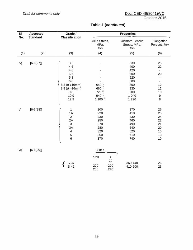
Table 1 Tensile Properties of Structural Steel Products (Clause 8.2.4.2)
Sl No.
Accepted Standard
Grade / Classification
Properties
Yield Stress MPa, Min
Ultimate Tensile Stress, MPa,
Min
Elongation Percent, Min
(1) (2) (3) (4) (5) (6)
i) [6-6(25)]
O D
DD EDD
- 280 250 220
- 270-410 270-370 270-350
- 28 32 35
ii) [6-6(18)] Ex40xx Ex41xx Ex42xx Ex43xx Ex44xx
Ex50xx Ex51xx Ex52xx Ex53xx Ex54xx Ex55xx Ex56xx
330 330 330 330 330
360 360 360 360 360 360 360
410-540 410-540 410-540 410-540 410-540
510-610 510-610 510-610 510-610 510-610 510-610 510-610
16 20 22 24 24
16 18 18 20 20 20 20
iii) [6-6(26)] O D
DD EDD
- - - -
- 240-400 260-390 260-380
- 25 28 32
Draft for comments only Doc: CED 46(8041)WC October 2015
39
Table 1 (continued)
Sl No.
Accepted Standard
Grade / Classification
Properties
Yield Stress, MPa, Min
Ultimate Tensile Stress, MPa,
Min
Elongation Percent, Min
(1) (2) (3) (4) (5) (6)
iv) [6-6(27)]
3.6 4.6 4.8 5.6 5.8 6.8
8.8 (d ≤16mm) 8.8 (d >16mm)
9.8 10.9 12.9
- - - - - -
640 1)
660
1)
720 1)
940
1)
1 100 1)
330 400 420 500 520 600 800 830 900
1 040 1 220
25 22 -
20 - -
12 12 10 9 8
v) [6-6(28)]
1 1A 2
2A 3
3A 4 5 6
200 220 230 250 270 280 320 350 370
370 410 430 460 490 540 620 710 740
26 25 24 22 21 20 15 13 10
vi) [6-6(29)]
St 37 St 42
d or t
360-440 410-500
26 23
≤ 20 > 20
220 250
200 240
Draft for comments only Doc: CED 46(8041)WC October 2015
40
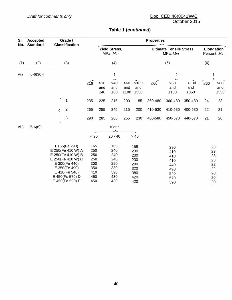
Table 1 (continued)
Sl No.
Accepted Standard
Grade / Classification
Properties Yield Stress, Ultimate Tensile Stress Elongation MPa, Min MPa, Min Percent, Min
(1)
(2)
(3)
(4) (5) (6)
vii) [6-6(30)] 1 2 3
t
t
t
16 >16 and
40
>40 and
60
>60 and
100
>100 and
350
60 >60 and
100
>100 and
350
60 >60 and
350
235
265
290
225
255
285
215
245
280
200
215
255
185
200
230
360-480
410-530
460-580
360-480
410-530
450-570
350-480
400-530
440-570
24
22
21
23
21
20
viii) [6-6(6)]
E165(Fe 290) E 250(Fe 410 W) A E 250(Fe 410 W) B E 250(Fe 410 W) C
E 300(Fe 440) E 350(Fe 490) E 410(Fe 540)
E 450(Fe 570) D E 450(Fe 590) E
d or t
290 410 410 410 440 490 540 570 590
23 23 23 23 22 22 20 20 20
< 20 20 - 40 > 40
165 250 250 250 300 350 410 450 450
165 240 240 240 290 330 390 430 430
165 230 230 230 280 320 380 420 420

Draft for comments only Doc: CED 46(8041)WC October 2015
41
Table 1 (continued)
Sl No.
Indian Standard Grade / Classification
Properties
Yield Stress, MPa Min
Ultimate Tensile Stress, MPa Min
Elongation Percent,
Min (1) (2) (3) (4) (5) (6)
ix) [6-6(31)] I II III
d or t
400-490 400-490 400-490
22 22 22
≤ 25 > 25 and ≤ 50
230 235 235
220 235 235
x) [6-6(32)] Grade 1
Grade 2
240
245
350-450
360-450
25
34
xi) [6-6(10)] Annealed Condition
As-Drawn Condition
160
190
330 - 410
410 - 490
30
20
Draft for comments only Doc: CED 46(8041)WC October 2015
42
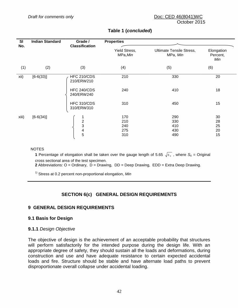
Table 1 (concluded)
Sl No.
Indian Standard Grade / Classification
Properties
Yield Stress, MPa,Min
Ultimate Tensile Stress, MPa, Min
Elongation Percent,
Min
(1) (2) (3) (4) (5) (6)
xii) [6-6(33)] HFC 210/CDS 210/ERW210 HFC 240/CDS 240/ERW240 HFC 310/CDS 310/ERW310
210
240
310
330
410
450
20
18
15
xiii) [6-6(34)] 1 2 3 4 5
170 210 240 275 310
290 330 410 430 490
30 28 25 20 15
NOTES
1 Percentage of elongation shall be taken over the gauge length of 5.65 0S , where S0 = Original
cross sectional area of the test specimen. 2 Abbreviations: O = Ordinary, D = Drawing, DD = Deep Drawing, EDD = Extra Deep Drawing.
1) Stress at 0.2 percent non-proportional elongation, Min
SECTION 6(c) GENERAL DESIGN REQUIREMENTS
9 GENERAL DESIGN REQUIREMENTS 9.1 Basis for Design 9.1.1 Design Objective The objective of design is the achievement of an acceptable probability that structures will perform satisfactorily for the intended purpose during the design life. With an appropriate degree of safety, they should sustain all the loads and deformations, during construction and use and have adequate resistance to certain expected accidental loads and fire. Structure should be stable and have alternate load paths to prevent disproportionate overall collapse under accidental loading.

Draft for comments only Doc: CED 46(8041)WC October 2015
43
9.1.2 Methods of Design 9.1.2.1 Structure and its elements shall normally, be designed by the limit state method. Account should be taken of accepted theories, experimental information and experience and the need to design for durability. Calculations alone may not produce safe, serviceable and durable structures. Suitable materials, quality control, adequate detailing and good supervision are equally important. 9.1.2.2 Where the limit states method cannot be conveniently adopted; the working stress design [see Section 6(k)] may be used. 9.1.3 Design Process Structural design, including design for durability, construction and use should be considered as a whole. The realization of design objectives requires compliance with clearly defined standards for materials, fabrication, erection and in-service maintenance. 9.2 Loads and Forces 9.2.1 For the purpose of designing any element, member or a structure, the following loads (actions) and their effects shall be taken into account, where applicable, with partial safety factors and combinations (see 11.3.3).
a) Dead loads; b) Imposed loads (live load, crane load, snow load, dust load, wave load, earth
pressures, etc); c) Wind loads; d) Earthquake loads; e) Erection loads; f) Accidental loads such as those due to blast, impact of vehicles, etc; and g) Secondary effects due to contraction or expansion resulting from temperature
changes, differential settlements of the structure as a whole or of its components, eccentric connections, rigidity of joints differing from design assumptions.
9.2.1.1 Dead loads should be assumed in design as specified in 2 of Section 1 of Part 6. 9.2.1.2 Imposed loads for different types of occupancy and function of structures shall be taken as recommended in 3 of Section 1 of Part 6. Imposed loads arising from equipment, such as cranes and machines should be assumed in design as per manufacturers/suppliers data (see 9.5.4). Snow load shall be taken as per in 6 of Section 1 of Part 6. 9.2.1.3 Wind loads on structures shall be taken as per the recommendations of 4 of Section 1 of Part 6.

Draft for comments only Doc: CED 46(8041)WC October 2015
44
9.2.1.3.1 Wind pressure In calculating the effective wind pressure on exposed circular tube members of a structure, the effective area shall be taken as 0.6 times the projected area of the member (refer 4 of Section 1 of Part 6). 9.2.1.4 Earthquake loads shall be assumed as per the recommendations of 5 of Section 1 of Part 6. 9.2.1.5 The erection loads and temperature effects shall be considered as specified in 9.3 and 9.4 respectively. 9.3 Erection Loads 9.3.1 All loads required to be carried by the structure or any part of it due to storage or positioning of construction material and erection equipment, including all loads due to operation of such equipment shall be considered as erection loads. Proper provision shall be made, including temporary bracings, to take care of all stresses developed during erection. Dead load, wind load and also such parts of the live load as would be imposed on the structure during the period of erection shall be taken as acting together with the erection loads. The structure as a whole and all parts of the structure in conjunction with the temporary bracings shall be capable of sustaining these loads during erection. 9.4 Temperature Effects 9.4.1 Expansion and contraction due to changes in temperature of the members and elements of a structure shall be considered and adequate provision made for such effect. 9.4.2 The temperature range varies for different localities and under different diurnal and seasonal conditions. The absolute maximum and minimum temperatures, which may be expected in different localities of the country, may be obtained from the Indian Metrological Department and used in assessing the maximum variations of temperature for which provision for expansion and contraction has to be made in the structure. 9.4.3 The range of variation in temperature of the building materials may be appreciably greater or lesser than the variation of air temperature and is influenced by the condition of exposure and the rate at which the materials composing the structure absorb or radiate heat. This difference in temperature variations of the material and air shall be given due consideration. The effect of differential temperature within an element or member, due to part exposure to direct sunlight shall also be considered. 9.4.4 The co-efficient of thermal expansion for steel is as given in 8.2.4.1(e).
Draft for comments only Doc: CED 46(8041)WC October 2015
45
9.5 Load Combinations 9.5.1 Load combinations for design purposes shall be those that produce maximum forces and effects and consequently maximum stresses and deformations. The following combination of loads with appropriate partial safety factors (see Table 4) may be considered.
a) Dead load + imposed load, b) Dead load + imposed load + wind or earthquake load, c) Dead load + wind or earthquake load, and d) Dead load + erection load.
NOTE – In the case of structures supporting cranes, imposed loads shall include the crane effects as given in 9.5.4.
9.5.2 Wind load and earthquake loads shall not be assumed to act simultaneously. The effect of each shall be considered separately. 9.5.3 The effect of cranes to be considered under imposed loads shall include the vertical loads, eccentricity effects induced by the vertical loads, impact factors, lateral (surge) and the longitudinal (horizontal) thrusts, not acting simultaneously, across and along the crane rail, respectively [see 3 of Section 1 of Part 6]. 9.5.4 The crane loads and their combinations to be considered shall be as indicated by the customer. In the absence of any specific indications, the load combinations shall be in accordance with the provisions in 3 of Section 1 of Part 6 or as given below:
a) Vertical loads with full impact from one loaded crane or two cranes in case of tandem operation, together with vertical loads without impact from as many loaded cranes as may be positioned for maximum effect, along with maximum horizontal thrust from one crane only or two in case of tandem operation;
b) Loads as specified in 9.5.4(a), subject to cranes in maximum of any two bays of the building cross-section shall be considered for multi-bay multi-crane gantries;
c) The longitudinal thrust on a crane track rail shall be considered for a maximum of two loaded cranes on the track; and
d) Lateral thrust (surge) and longitudinal thrust acting across and along the crane rail respectively, shall be assumed not to act simultaneously. The effect of each force, shall however be investigated separately.
9.5.5 While investigating the effect of earthquake forces, the resulting effect from dead loads of all cranes parked in each bay, positioned to cause maximum effect shall be considered. 9.5.6 The crane runway girders supporting bumpers shall be checked for bumper impact loads also, as specified by the manufacturers.

Draft for comments only Doc: CED 46(8041)WC October 2015
46
9.5.7 Stresses developed due to secondary effects such as handling; erection, temperature and settlement of foundations, if any, shall be appropriately added to the stresses calculated from the combination of loads stated in 9.5.1, with appropriate partial safety factors. 9.6 Geometrical Properties 9.6.1 General The geometrical properties of the gross and the effective cross-sections of a member or part thereof, shall be calculated on the following basis.
a) The properties of the gross cross-section shall be calculated from the specified size of the member or part thereof or read from appropriate table.
b) The properties of the effective cross-section shall be calculated by deducting from the area of the gross cross-section, the following:
i) The sectional area in excess of effective plate width, in case of slender
sections (see 9.7.2). ii) The sectional areas of all holes in the section except for parts in
compression. In case of punched holes, hole size 2 mm in excess of the actual diameter may be deducted.
9.7 Classification of Cross-Sections 9.7.1 Plate elements of a cross-section may buckle locally due to compressive stresses. The local buckling can be avoided before the limit state is achieved by limiting the width to thickness ratio of each element of a cross-section subjected to compression due to axial force, moment or shear. 9.7.1.1 When plastic analysis is used, the members shall be capable of forming plastic hinges with sufficient rotation capacity (ductility) without local buckling, to enable the redistribution of bending moment required before formation of the failure mechanism. 9.7.1.2 When elastic analysis is used, the member shall be capable of developing the yield stress under compression without local buckling. 9.7.2 On basis of the above, four classes of sections are defined as follows:
a) Class 1 (Plastic) Cross-sections, which can develop plastic hinges and have the rotation capacity required for failure of the structure by formation of plastic mechanism. The width to thickness ratio of plate elements shall be less than that specified under Class 1 (Plastic), in Table 2.

Draft for comments only Doc: CED 46(8041)WC October 2015
47
b) Class 2 (Compact) Cross-sections, which can develop plastic moment of resistance, but have inadequate plastic hinge rotation capacity for formation of plastic mechanism, due to local buckling. The width to thickness ratio of plate elements shall be less than that specified under Class 2 (Compact), but greater than that specified under Class 1 (Plastic), in Table 2.
c) Class 3 (Semi-Compact) Cross-sections, in which the extreme fiber in compression can reach yield stress, but cannot develop the plastic moment of resistance, due to local buckling. The width to thickness ratio of plate elements shall be less than that specified under Class 3 (Semi-Compact),but greater than that specified under Class 2 (Compact), in Table 2.
d) Class 4 (Slender) Cross-sections in which the elements buckle locally even before reaching yield stress. The width to thickness ratio of plate elements shall be greater than that specified under Class 3 (Semi-Compact), in Table 2. In such cases, the effective sections for design shall be calculated either by following the provisions of good practice [6-6(35)] to account for the post-local-buckling strength or by conservatively deducting width of the compression plate element in excess of the semi-compact section limit (see Fig. 2b). The design of slender web elements in flexural members may be done as given in 14.2.1.1 for flexure and 14.4.2.2 for shear
When different elements of a cross-section fall under different classes, the section shall be classified as governed by the most critical element. The maximum value of limiting width to thickness ratios of elements for different classifications of sections are given in Table 2a. The effective section in case of class 4 (slender elements) may be conservatively taken as shown in Fig. 2b. 9.7.3 Types of Elements
a) Internal elements These are elements attached along both longitudinal edges to other elements or to longitudinal stiffeners connected at suitable intervals to transverse stiffeners; for example web of I-section and flanges and web of box section.
b) Outside elements or outstands These are elements attached along only one of the longitudinal edges to an adjacent element, the other edge being free to displace out of plane, for example flange overhang of an I-section, stem of T-section and legs of an angle section.
c) Tapered elements These may be treated as flat elements having average thickness as defined in accepted standard [6-6(36)].
The design of slender compression element (Class 4) considering the strength beyond elastic local buckling of element is outside the scope of this section. Reference may be

Draft for comments only Doc: CED 46(8041)WC October 2015
48
made to in good practice [6-6(35)] for such design provisions. The design of slender web elements may be made as given in 14.2.1.1 for flexure and 14.4.2.2 for shear. 9.7.4 Compound Elements in Built-up Section (see Fig. 2) In case of compound elements consisting of two or more elements bolted or welded together, the limiting width to thickness ratios as in Table 2 should be considered on basis of the following:
a) Outstanding width of compound element (be) to its own thickness. b) The internal width of each added plate between the lines of welds or fasteners
connecting it to the original section to its own thickness. c) Any outstand of the added plates beyond the line of welds or fasteners
connecting it to original section to its own thickness.

Draft for comments only Doc: CED 46(8041)WC October 2015
49
Table 2 Limiting Width to Thickness Ratio (Clause 9.7.2 and 9.7.4)
_________________________________________________________________
Sl No.
Compression Element Ratio
Class of Section
Class 1 Plastic
Class 2 Compact
Class 3 Semi-Compact
(1) (2) (3) (4) (5) (6)
i) Outstanding element of compression flange
Rolled section b/tf 9.4 10.5 15.7
Welded section b/tf 8.4 9.4 13.6
ii) Internal element of compression flange
Compression due to bending
b/tf 29.3 33.5 42
Axial compression
b/tf Not applicable
iii)
Web of an I, H or box section
Neutral axis at mid-depth d/tw 84 105 126
Generally
If r1
is negative:
d/tw
11
8
r
4
but ≥ 42
11
105.0
r
ε
221
0.126
r
but ≥ 42 If r1
is
positive : d/tw 11.51
105.0
r
but ≥ 42
Axial compression d/tw Not applicable 42 iv)
Web of a channel d/tw
42 42 42
v) Angle, compression due to bending (Both criteria should be satisfied)
b/t d/t
9.4
9.4
10.5
10.5
15.7
15.7 vi) Single angle, or double angles with the
components separated, axial compression (All three criteria should be satisfied)
b/t d/t (b+d)/t
Not applicable
15.7
15.7
25
vii) Outstanding leg of an angle in contact back-to-back in a double angle member
d/t 9.4 10.5 15.7
viii) Outstanding leg of an angle with its back in continuous contact with another component
d/t 9.4 10.5 15.7
ix) Stem of a T-section, rolled or cut from a rolled I- or H-section
d/t 8.4 9.4 18.9
x) Circular hollow tube, including welded tube subjected to: a) moment
D/t
422
522
1462
b) axial compression D/t Not applicable 882
NOTES 1 Elements which exceed semi-compact limits are to be taken as of slender cross-section 2 ξ = (250 / fy )
1/2
3 Webs shall be checked for shear buckling in accordance with 14.4.2 when d/t > 67ξ. Where, b is the width of the element may be taken as clear distance between lateral supports or between lateral support and free edge, as appropriate, t is the thickness of element, d is the depth of the web, D is the outer diameter of the element (see Fig 2, 9.7.3 and 9.7.4).
4 Different elements of a cross-section can be in different classes. In such cases the section is classified based on the least favourable classification.
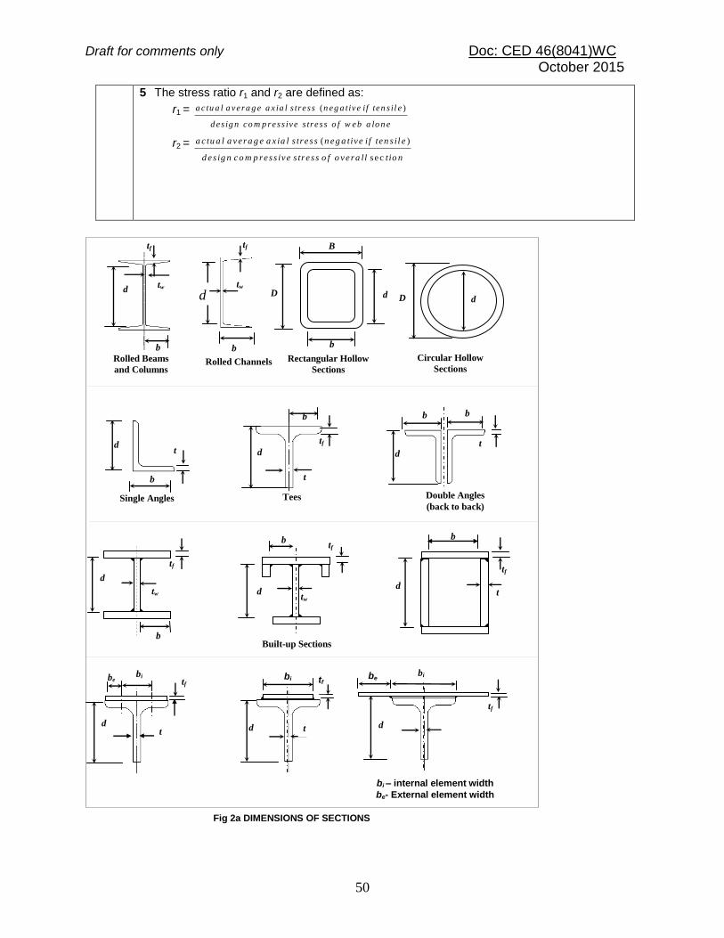
Draft for comments only Doc: CED 46(8041)WC October 2015
50
5 The stress ratio r1 and r2 are defined as:
r1 = ( )a c tu a l a vera g e a x ia l s tress n eg a tive if ten s il e
d es ig n co m p ress ive s tress o f w eb a lo n e
r2 = ( )
sec
a c tu a l a vera g e a x ia l s tre ss n eg a tive if ten s il e
d es ig n co m p ress ive s tre ss o f o vera ll tio n
b
Fig 2a DIMENSIONS OF SECTIONS
tw
tf
d
Rolled Channels
D d
b
B
Rectangular Hollow
Sections
Circular Hollow
Sections
D d
Rolled Beams
and Columns
tf
b
d tw
Double Angles
(back to back) Single Angles
d
b
t
t
tf
b
d
Tees
d
b b
t
Built-up Sections
d
b tf
tw
d
b
tf
tw
d
b
t
tf
be
d
tf
bi
bi – internal element width
be- External element width
be tf
t
bi
d d
bi tf
t
d

Draft for comments only Doc: CED 46(8041)WC October 2015
51
9.8 Maximum Effective Slenderness Ratio 9.8.1 The maximum effective slenderness ratio, KL/r, values of a beam, strut or tension member shall not exceed those given in Table 3. ‘KL’ is the effective length of the member and ‘r’ is appropriate radius of gyration based on the effective section as defined in 9.6.1.
Table 3 Maximum Values of Effective Slenderness Ratios
(Clause 9.8.1)
Sl No.
Member
Maximum Effective
Slenderness Ratio (KL/r)
(1)
(2) (3)
i) A member carrying compressive loads resulting from dead loads and imposed loads
180
ii) A tension member in which a reversal of direct stress occurs due to loads other than wind or seismic forces
180
iii) A member subjected to compression forces resulting only from combination with wind/earthquake actions, provided the deformation of such member does not adversely affect the stress in any part of the structure
250
iv) Compression flange of a beam against lateral torsional buckling 300 v) A member normally acting as a tie in a roof truss or a bracing
system not considered effective when subject to possible reversal of stress into compression resulting from the action of wind or earthquake forces
1)
350
vi) Members always under tension1)
(other than pre-tensioned members)
400
t
15.7 t
15
.7
t
t
tf
tw
15.7 tf
21
t w
21
t w
t
t
21 t 21 t
21
t 2
1
t
tw
31.4 tf
21
t w
21
t w
tf
FIG. 2b EFFECTIVE SECTION OF SLENDER ELEMENTS
Draft for comments only Doc: CED 46(8041)WC October 2015
52
1)
Tension members, such as bracings, pre-tensioned to avoid sag, need not satisfy the maximum slenderness ratio limits.
9.9 Resistance to Horizontal Forces 9.9.1 In designing the steel frame work of a building, provision shall be made (by adequate moment connections or by a system of bracing) to effectively transmit to the foundations all the horizontal forces, giving due allowance for the stiffening effect of the walls and floors, where applicable. 9.9.2 When the walls, or walls and floors and/or roofs are capable of effectively transmitting all the horizontal forces directly to the foundations, the structural steel framework may be designed without considering the effect of wind or earthquake. 9.9.3 Wind and earthquake forces are reversible and therefore call for rigidity and strength under force reversal in both longitudinal and transverse directions. To resist torsional effects of wind and earthquake forces, bracings in plan should be provided and integrally connected with the longitudinal and transverse bracings, to impart adequate torsional resistance to the structure. 9.9.3.1 In shed type steel mill buildings, adequate bracings shall be provided to transfer the wind or earthquake loads from their points of action to the appropriate supporting members. Where the connections to the interior columns or frames are designed such that the wind or earthquake loads will not be transferred to the interior columns, the exterior columns or frames shall be designed to resist the total wind or earthquake loads. Where the connections to the interior columns and frames are designed such that the wind or earthquake effects are transferred to the interior columns also, and where adequate rigid diaphragm action can be mobilized as in the case of the cast-in place RC slab, both exterior and interior columns and frames may be designed on the assumption that the wind or earthquake load is divided among them in proportion to their relative stiffness. Columns also should be designed to withstand the net uplifting effect caused by excessive wind or earthquake. Additional axial forces arising in adjacent columns due to the vertical component of bracings or due to frame action shall also be accounted for. 9.9.3.2 Earthquake forces are proportional to the seismic mass as defined in 5 of Section 1 of Part 6. Earthquake forces should be applied at the centre of gravity of all such components of mass and their transfer to the foundation should be ensured. Other construction details, stipulated in good practice [6-6(37)] should also be followed. 9.9.3.3 In buildings where high-speed traveling cranes are supported or where a building or structure is otherwise subjected to vibration or sway, triangulated bracing or rigid portal systems shall be provided to reduce the vibration or sway to an acceptable minimum.

Draft for comments only Doc: CED 46(8041)WC October 2015
53
9.9.4 Foundations The foundations of a building or other structures shall be designed to provide the rigidity and strength that has been assumed in the analysis and design of the superstructure. 9.9.5 Eccentrically placed loads Where a wall, or other gravity load, is placed eccentrically upon the flange of a supporting steel beam, the beam and its connections shall be designed for torsion, unless the beam is restrained laterally in such a way as to prevent the twisting of the beam. 9.10 Expansion Joints 9.10.1 In view of the large number of factors involved in deciding the location, spacing and nature of expansion joints, the decision regarding provision of expansion joints shall be left to the discretion of the designer. 9.10.2 Structures in which marked changes in plan dimensions take place abruptly, shall be provided with expansion joints at the section where such changes occur. Expansion joints shall be so provided that the necessary movement occurs with minimum resistance at the joint. The gap at the expansion joint should be such that;
a) It accommodates the expected expansion/contraction due to seasonal and diurnal variation of temperature, and
b) It avoids pounding of adjacent units under earthquake. The structure
adjacent to the joint should preferably be supported on separate columns but not necessarily on separate foundations.
9.10.3 The details as to the length of a structure where expansion joints have to be provided may be determined after taking into consideration various factors such as temperature, exposure to weather and structural design. The provisions in 9.10.3.1 to 9.10.3.3 are given as general guidance. 9.10.3.1 If one bay of longitudinal bracing is provided at the centre of the building or building section, the length of the building section may be restricted to 180 m in case of covered buildings and 120 m in case of open gantries (see Fig.3). 9.10.3.2 If more than one bay of longitudinal bracing is provided near the centre of the building/section, the maximum centre line distance between the two lines of bracing may be restricted to 50 m for covered buildings (and 30 m for open gantries) and the maximum distance between the centre of the bracing to the nearest expansion joint/end of building or section may be restricted to 90 m (60 m in case of open gantries). The maximum length of the building section thus may be restricted to 230 m for covered

Draft for comments only Doc: CED 46(8041)WC October 2015
54
buildings (150 m for open gantries). Beyond this, suitable expansion joints shall be provided (see Fig.4). 9.10.3.3 The maximum width of the covered building section should preferably be restricted to 150 m beyond which suitable provisions for the expansion joint may be made. 9.10.4 When the provisions of these sections are met for a building or open structure, the stress analysis due to temperature is not required.
END OF BUILDING/SECTION
180 m
FIG. 3 MAXIMUM LENGTH OF BUILDING WITH ONE BAY OF BRACING
90 m
EXPANSION JOINT
90 m 50 m
FIG. 4 MAXIMUM LENGTH OF COVERED BUILDING/SECTION WITH TWO BAYS OF BRACINGS

Draft for comments only Doc: CED 46(8041)WC October 2015
55
SECTION 6(d) METHODS OF STRUCTURAL ANALYSIS 10 METHODS OF STRUCTURAL ANALYSIS 10.1 Methods of Determining Action Effects 10.1.1 General For the purpose of complying with the requirements of the limit states of stability, strength and serviceability specified in Section 6(e), effects of design actions on a structure and its members and connections, shall be determined by structural analysis using the assumptions of 10.2 and 10.3 and one of the following methods of analysis:
a) Elastic analysis in accordance with 10.4, b) Plastic analysis in accordance with 10.5, c) Advanced analysis in accordance with Annex A, or d) Dynamic analysis in accordance with 5 of Section 1 of Part 6.
The design action effects for design basis earthquake loads shall be obtained only by an elastic analysis. The maximum credible earthquake loads shall be assumed to correspond to the load at which significant plastic hinges are formed in the structure and the corresponding effects shall be obtained by plastic or advanced analysis. More information on analysis and design to resist earthquake is given in Section 6(l) and 5 of Section 1 of Part 6. 10.1.2 Non-sway and Sway Frames For the purpose of analysis and design, the structural frames are classified as non-sway and sway frames as given below:
a) Non-sway frame ― One in which the transverse displacement of one end of the member relative to the other end is effectively prevented. This applies to triangulated frames and trusses or to frames where in-plane stiffness is provided by bracings, or by shear walls, or by floor slabs and roof decks secured horizontally to walls or to bracing systems parallel to the plane of loading and bending of the frame.
b) Sway frame ― One in which the transverse displacement of one end of the member
relative to the other end is not effectively prevented. Such members and frames occur in structures which depend on flexural action of members to resist lateral loads and sway, as in moment resisting frames.
c) A rigid jointed multi-storey frame may be considered as a non-sway frame if in every
individual storey, the deflection , over a storey height hs, due to the notional horizontal loading given in 10.3.6 satisfies the following criteria:

Draft for comments only Doc: CED 46(8041)WC October 2015
56
i) For clad frames, when the stiffening effect of the cladding is not taken into account in the deflection calculations:
0002
sh
ii) For unclad frame or clad frames, when the stiffening effect of the cladding is taken into account in the deflection calculations:
0004
sh
iii) A frame, which when analyzed considering all the lateral supporting system does
not comply with the above criteria, should be classified as a sway frame, even if it is braced or otherwise laterally stiffened.
10.2 Forms of Construction Assumed for Structural Analysis 10.2.1 The effects of design action in the members and connections of a structure shall be determined by assuming singly or in combination of the following forms of construction (see 16.6.1). 10.2.1.1 Rigid construction In rigid construction, the connections between members (beam and column) at their junction shall be assumed to have sufficient rigidity to hold the original angles between the members connected at a joint unchanged under loading. 10.2.1.2 Semi-rigid construction In semi-rigid construction, the connections between members (beam and column) at their junction may not have sufficient rigidity to hold the original angles between the members at a joint unchanged, but shall be assumed to have the capacity to furnish a dependable and known degree of flexural restraint. The relationship between the degree of flexural restraint and the level of the load effects shall be established by any rational method or based on test results (see Annex E). 10.2.1.3 Simple construction In simple construction, the connections between members (beam and column) at their junction will not resist any appreciable moment and shall be assumed to be hinged. 10.2.2 Design of connections The design of all connections shall be consistent with the form of construction, and the behaviour of the connections shall not adversely affect any other part of the structure beyond what is allowed for in design. Connections shall be designed in accordance with Section 6(j).

Draft for comments only Doc: CED 46(8041)WC October 2015
57
10.3 Assumptions in Analysis 10.3.1 The structure shall be analyzed in its entirety except as follows:
a) Regular building structures, with orthogonal frames in plan, may be analyzed as a series of parallel two-dimensional sub-structures (part of a structure), the analysis being carried out in each of the two directions, at right angles to each other, except when there is significant load redistribution between the sub-structures (part of a structure). For earthquake loading three dimensional analysis may be necessary to account for effects of torsion and also for multi-component earthquake forces (see 5 of Section 1 of Part 6).
b) For vertical loading in a multi-storey building structure, provided with bracing or
shear walls to resist all lateral forces, each level thereof, together with the columns immediately above and below, may be considered as a substructure, the columns being assumed fixed at the ends remote from the level under consideration.
c) Where beams at a floor level in a multi-bay building structure are considered as a
sub-structure (part of a structure), the bending moment at the support of the beam due to gravity loads may be determined based on the assumption that the beam is fixed at the far end support, one span away from the span under consideration, provided that the floor beam is continuous beyond that support point.
10.3.2 Span Length The span length of a flexural member in a continuous frame system shall be taken as the distance between centre-to-centre of the supports. 10.3.3 Arrangements of Imposed Loads in Buildings For building structures, the various arrangements of imposed loads considered for the analysis, shall include at least the following:
a) Where the loading pattern is fixed, the arrangement concerned. b) Where the imposed load is variable and not greater than three-quarters of the dead
load, the live load may be taken to be acting on all spans.
c) Where the imposed load is variable and exceeds three-quarters of the dead load, arrangements of live load acting on the floor under consideration shall include the following cases:
i) the imposed load on alternate spans, ii) the imposed load on two adjacent spans, and iii) the imposed load on all the spans.
Draft for comments only Doc: CED 46(8041)WC October 2015
58
10.3.4 Base Stiffness In the analysis of all structures the appropriate base stiffness about the axis under consideration shall be used. In the absence of the knowledge of the pedestal and foundation stiffness, the following may be assumed:
a) When the column is rigidly connected to a suitable foundation, the stiffness of the pedestal shall be taken as the stiffness of the column above base plate. However in case of very stiff pedestals and foundations the column may be assumed as fixed at base.
b) When the column is nominally connected to the foundation, a pedestal stiffness of
10 percent of the column stiffness may be assumed.
c) When an actual pin or rocker is provided in the connection between the steel column and pedestal, the column is assumed as hinged at base and the pedestal and foundation may be appropriately designed for the reactions from the column.
d) In case of (a) and (b), the bottom of the pedestal shall be assumed to have the
following boundary condition in the absence of any detailed procedure based on theory or tests:
i) When the foundation consist of a group of piles with a pile cap, raft foundation or
an isolated footing resting on rock or very hard soil, the pedestal shall be assumed to be fixed at the level of the bottom of footing or at the top of pile cap.
ii) When the foundation consists of an isolated footing resting on other soils, pedestal shall be assumed to be hinged at the level of the bottom of footing.
iii) When the pedestal is supported by a single pile, which is laterally surrounded by soil providing passive resistance, the pile shall be assumed to be fixed at a depth of 5 times the diameter of the pile below the ground level in case of compact ground or the top level of compact soil in case of poor soil overlying compact soil.
iv) When the column is founded into rock, it may be assumed to be fixed at the interface of the column and rock.
10.3.5 Simple Construction Bending members may be assumed to have their ends connected for shear only and to be free to rotate. In triangulated structures, axial forces may be determined by assuming that all members are pin connected. The eccentricity for stanchion and column shall be assumed in accordance with 13.3.3. 10.3.6 Notional Horizontal Loads To analyze a frame subjected to gravity loads, considering the sway stability of the frame, notional horizontal forces should be applied. These notional horizontal forces account for

Draft for comments only Doc: CED 46(8041)WC October 2015
59
practical imperfections and should be taken at each level as being equal to 0.5 percent of factored dead load plus vertical imposed loads applied at that level. The notional load should not be applied along with other lateral loads such as wind and earthquake loads in the analysis. 10.3.6.1 The notional forces should be applied on the whole structure, in both orthogonal directions, in one direction at a time, at roof and all floor levels or their equivalent. They should be taken as acting simultaneously with factored gravity loads. 10.3.6.2 The notional force should not be:
a) applied when considering overturning or overall instability; b) combined with other horizontal (lateral) loads; c) combined with temperature effects, and d) taken to contribute to the net shear on the foundation.
10.3.6.3 The sway effect using notional load under gantry load case need not be considered if the ratio of height to lateral width of the building is less than unity. 10.4 Elastic Analysis 10.4.1 Assumptions Individual members shall be assumed to remain elastic under the action of the factored design loads for all limit states. The effect of haunching or any variation of the cross-section along the axis of a member shall be considered, and where significant, shall be taken into account in the determination of the member stiffness. 10.4.2 First-order Elastic Analysis 10.4.2.1 In a first-order elastic analysis, the equilibrium of the frame in the undeformed geometry is considered, the changes in the geometry of the frame due to the loading are not accounted for, and changes in the effective stiffness of the members due to axial force are neglected. The effects of these on the first-order bending moments shall be allowed for by using one of the methods of moment amplification of 10.4.3.2 or 10.4.3.3 as appropriate. Where the moment amplification factor Ky, Kz, calculated in accordance with 10.4.3.2 or 10.4.3.3 as appropriate, is greater than 1.4, a second-order elastic analysis in accordance with Annex A shall be carried out. 10.4.3 Second-order Elastic Analysis 10.4.3.1 The analysis shall allow for the effects of the design loads acting on the structure and its members in their displaced and deformed configuration. These second-order effects shall be taken into account by using either:

Draft for comments only Doc: CED 46(8041)WC October 2015
60
a) A first-order elastic analysis with moment amplification in accordance with 10.4.2,
provided the moment amplification factors, Ky and Kz are not greater than 1.4; or b) A second-order elastic analysis in accordance with Annex A.
10.4.3.2 Moment amplification for members in non-sway frames For a member with zero axial compression or a member subject to axial tension, the design bending moment is that obtained from the first order analysis for factored loads, without any amplification. For a braced member with a design axial compressive force Pd as determined by the first order analysis, the design bending moment shall be calculated considering moment amplification as in 15.3.2.2. 10.4.3.3 Moment amplification for members in sway frames The design bending moment shall be calculated as the product of moment amplification factor, [see 15.3.2.2 (Ky, Kz)] and the moment obtained from the first order analysis of the sway frame, unless analysis considering second order effects is carried out (see 10.4.3). 10.4.3.4 The calculated bending moments from the first order elastic analysis may be modified by redistribution upto 15 percent of the peak calculated moment of the member under factored load, provided that:
a) The internal forces and moments in the members of the frame are in equilibrium with applied loads.
b) All the members in which the moments are reduced shall belong to plastic or compact section classification (see 9.7).
10.5 Plastic Analysis 10.5.1 Application The effects of design action throughout or on part of a structure may be determined by a plastic analysis, provided that the requirements of 10.5.2 are met. The distribution of design action effects shall satisfy equilibrium and the boundary conditions. 10.5.2 Requirements When a plastic method of analysis is used, all of the following conditions shall be satisfied, unless adequate ductility of the structure and plastic rotation capacity of its members and connections are established for the design loading conditions by other means of evaluation:
a) The yield stress of the grade of the steel used shall not exceed 450 MPa.

Draft for comments only Doc: CED 46(8041)WC October 2015
61
b) The stress-strain characteristics of the steel shall not be significantly different from
those obtained for steels complying with the accepted standard [6-6(6)] or equivalent and shall be such as to ensure complete plastic moment redistribution. The stress-strain diagram shall have a plateau at the yield stress, extending for at least six times the yield strain. The ratio of the tensile strength to the yield stress specified for the grade of the steel shall not be less than 1.2. The elongation on a gauge length complying to the accepted standard [6-6(6)] shall not be less than 15 percent; and the steel shall exhibit strain-hardening capability. Steels conforming to the accepted standard [6-6(6)] shall be deemed to satisfy the above requirements.
c) The members used shall be hot-rolled or fabricated using hot-rolled plates and
sections.
d) The cross section of members not containing plastic hinges should be at least that of compact section (see 9.7.2), unless the members meet the strength requirements from elastic analysis.
e) Where plastic hinges occur in a member, the proportions of its cross section should
not exceed the limiting values for plastic section given in 9.7.2.
f) The cross section should be symmetrical about its axis perpendicular to the axis of the plastic hinge rotation.
g) The members shall not be subject to impact loading, requiring fracture assessment
or fluctuating loading, requiring a fatigue assessment [see SECTION 6(m)]. 10.5.2.1 Restraints If practicable, torsional restraint (against lateral buckling) should be provided at all plastic hinge locations. Where not feasible, the restraint should be provided within a distance of D/2 of the plastic hinge location, where D is the total depth of section. The torsional restraint requirement at a section as above, need not be met at the last plastic hinge to form, provided it can be clearly identified. Within a member containing a plastic hinge, the maximum distance Lm from the restraint at the plastic hinge to an adjacent restraint should be calculated by any rational method or the conservative method given below, so as to prevent lateral buckling. Conservatively Lm (in mm) may be taken as
1/2
2
t
2
yc
y
m
40250130
38
xff
rL
Draft for comments only Doc: CED 46(8041)WC October 2015
62
where
fc = actual compressive stress on the cross-section due to axial load, in N/mm2, fy = yield stress, in N/mm2; ry = radius of gyration about the minor axis in mm;
xt = torsional index, 0.5
tywt)/(132.1 IIAIx ;
A = area of cross-section; and Iw, Iy, It = warping constant, second moment of the cross section above the minor axes and St. Venant’s torsion constant, respectively. Where the member has unequal flanges, ry should be taken as the lesser of the values of the compression flange only or the whole section. Where the cross section of the member varies within the length Lm, the maximum value of ry and the minimum value of xt should be used. The spacing of restraints to member lengths not containing a plastic hinge should satisfy the recommendations of section on lateral buckling strength of beams (see 14.2.2). Where the restraints are placed at the limiting distance Lm, no further checks are required. 10.5.2.2 Stiffeners at plastic hinge locations Web stiffeners should be provided where a concentrated load, which exceeds 10 percent of the shear capacity of the member, is applied within D/2 of a plastic hinge location, (see 14.2.1.2). The stiffener should be provided within a distance of half the depth of the member on either side of the hinge location and be designed to carry the applied load in accordance with 14.7.4. If the stiffeners are flat plates, the outstand width to the thickness ratio, b/t, should not exceed the values given in the plastic section (see 9.7, Table 2).
Where other sections are used, the ratio
1/2
t
so
I
I, should not exceed the values given for
plastic section (for simple outstand, as in 9.7); where
Iso = second moment of area of the stiffener about the face of the element perpendicular to the web; and It = St. Venant’s torsion constant of the stiffener.
10.5.2.3 The frame shall be adequately supported against sway and out-of-plane buckling, by bracings, moment resisting frame or an independent system such as shear wall.

Draft for comments only Doc: CED 46(8041)WC October 2015
63
10.5.2.4 Fabrication restriction Within a length equal to the member depth, on either side of a plastic hinge location, the following restrictions should be applied to the tension flange and noted in the design drawings. Holes if required, should be drilled or else punched 2 mm undersize and reamed. All sheared or hand flame cut edges should be finished smooth by grinding, chipping or planning. 10.5.3 Assumptions in Analysis The design action effects shall be determined using a rigid-plastic analysis. It shall be permissible to assume full strength or partial strength connections, provided the capacities of these are used in the analysis, and provided that,
a) In a full strength connection, the moment capacity of the connection shall be not less than that of the member being connected;
b) In a partial strength connection, the moment capacity of the connection may be less than that of the member being connected; and
c) In both cases the behavior of the connection shall be such as to allow all plastic hinges necessary for the collapse mechanism to develop, and shall be such that the required plastic hinge rotation does not exceed the rotation capacity at any of the plastic hinges in the collapse mechanism.
In the case of building structures, it is not normally necessary to consider the effect of alternating plasticity. 10.5.4 Second-order Elastic Analysis Any second-order effects of the loads acting on the structure in its deformed configuration may be neglected, provided the following are satisfied:
a) For clad frames, provided the stiffening effects of masonry infill wall panels or diaphragms of profiled wall panel is not taken into account, and where elastic
buckling load factor, λcr (see 10.6) satisfies λcr/λp 10.
If 10 > λcr/λp 4.6 the second-order effects may be considered by amplifying the
design load effects obtained from plastic analysis by a factor p = {0.9 λcr /( λcr - 1)}. If λcr/ λp < 4.6, second-order elasto-plastic analysis or second order elastic analysis (see 10.4.3) is to be carried out.
b) for un-clad frames or for clad frames where the stiffening effects of masonry infill or
diaphragms of profiled wall panel is taken into account, where elastic buckling load
factor, λcr (see 10.6) satisfies λcr/ λp 20

Draft for comments only Doc: CED 46(8041)WC October 2015
64
If 20 > λcr/λp 5.75 the second-order effects may be considered by amplifying the
design load effects obtained from plastic analysis by a factor p = {0.9 λcr /( λcr -1)}. If λcr/ λp < 5.75, second-order elasto-plastic analysis or second-order elastic analysis (see 10.4.3) shall be carried out.
10.6 Frame Buckling Analysis
10.6.1 The elastic buckling load factor (cr) shall be the ratio of the elastic buckling load set of the frame to the design load set for the frame, and shall be determined in accordance with 10.6.2.
NOTE – The value of cr depends on the load set and has to be evaluated for each possible set of load combination.
10.6.2 In-plane frame buckling
The elastic buckling load factor (cr) of a rigid-jointed frame shall be determined by using:
a) One of the approximate methods of 10.6.2.1 and 10.6.2.2, or b) A rational elastic buckling analysis of the whole frame.
10.6.2.1 Regular non-sway frames (see 10.1.2) In a rectangular non-sway frame with regular loading and negligible axial forces in the beams, the Euler buckling stress fcc, for each column shall be determined in accordance
with 13.1.2.1. The elastic buckling load factor (cr) for the whole frame shall be taken as the lowest of the ratio of (fcc/fcd) for all the columns, where fcd is the axial compressive stress in the column from the factored load analysis. 10.6.2.2 Regular sway frames In a rectangular sway frame with regular loading and negligible axial forces in the beams, the buckling load, Pcc, for each column shall be determined as Pcc = A fcc where fcc is the elastic buckling stress of the column in the plane of frame, obtained in accordance with
13.1.2.1. The elastic buckling load factor cr, for the whole frame shall be taken as the
lowest of all the ratios, scr, calculated for each storey of the building, as given below:
LP
LP
/
/cc
scr
where P = member axial force from the factored load analysis, with tension taken
Draft for comments only Doc: CED 46(8041)WC October 2015
65
as negative L = column length and the summation includes all columns in the plane frame within a storey.
SECTION 6 (e) LIMIT STATE DESIGN
11 LIMIT STATE DESIGN
11.1 Basis for Design
11.1.1 In the limit state design method, the structure shall be designed to withstand safely all loads likely to act on it throughout its life. It shall not suffer total collapse under accidental loads such as from explosions or impact or due to consequences of human error to an extent beyond the local damages. The objective of the design is to achieve a structure that will remain fit for use during its life with acceptable target reliability. In other words, the probability of a limit state being reached during its lifetime should be very low. The acceptable limit for the safety and serviceability requirements before failure occurs is called a limit state. In general, the structure shall be designed on the basis of the most critical limit state and shall be checked for other limit states. 10.1.2 Steel structures are to be designed and constructed to satisfy the design requirements with regard to stability, strength, serviceability, brittle fracture, fatigue, fire, and durability such that they meet the following:
a) Remain fit with adequate reliability and be able to sustain all actions (loads) and other influences experienced during construction and use;
b) Have adequate durability under normal maintenance; c) Do not suffer overall damage or collapse disproportionately under accidental
events like explosions, vehicle impact or due to consequences of human error to an extent beyond local damage. The potential for catastrophic damage shall be limited or avoided by appropriate choice of one or more of the following:
1) Avoiding, eliminating or reducing exposure to hazards, which the structure is
likely to sustain. 2) Choosing structural forms, layouts and details and designing such that:
i) the structure has low sensitivity to hazardous conditions; and ii) the structure survives with only local damage even after serious damage
to any one individual element by the hazard; 3) Choosing suitable material, design and detailing procedure, construction
specifications, and control procedures for shop fabrication and field construction as relevant to the particular structure.

Draft for comments only Doc: CED 46(8041)WC October 2015
66
The following conditions may be satisfied to avoid a disproportionate collapse:
a) The building should be effectively tied together at each principal floor level and each column should be effectively held in position by means of continuous ties (beams) nearly orthogonal, except where the steel work supports only cladding weighing not more than 0.7 kN/m2 along with imposed and wind loads. These ties must be steel members such as beams, which may be designed for other purposes, steel bar reinforcement anchoring the steel frame to concrete floor or steel mesh reinforcement in composite slab with steel profiled sheeting directly connected to beam with shear connectors. These steel ties and their end connections should be capable of resisting factored tensile force not less than the factored dead and imposed loads acting on the floor area tributary to the tie nor less than 75 kN. Such connection of ties to edge column should also be capable of resisting 1 percent of the maximum axial compression in the column at the level due to factored dead and imposed loads. All column splices should be capable of resisting a tensile force equal to the largest of a factored dead and live load reaction from a single floor level located between that column splice and the next column splice below that splice. Lateral load system to resist notional horizontal loads prescribed in 10.3.6 should be distributed throughout the building in nearly orthogonal directions so that no substantial portions is connected at only one point to such a system. Precast concrete or other heavy floor or roof units should be effectively anchored in the direction of their span either to each other over the support or directly to the support.
b) Where the above conditions to tie the columns to the floor adequately are not satisfied each storey of the building should be checked to ensure that disproportionate collapse would not precipitate by the notional removal, one at a time, of each column.
c) Where each floor is not laterally supported by more than one system, check should be made at each storey by removing one such lateral support system at a time to ensure that disproportionate collapse would not occur. The collapse is considered disproportionate, if more than 15 percent of the floor or roof area of 70 m2 collapse at that level and at one adjoining level either above or below it, under a load equal to 1.05 or 0.9 times the dead load, 0.33 times temporary or full imposed load of permanent nature (as in storage buildings) and 0.33 times wind load acting together.
11.1.3 Structures designed for unusual or special functions shall comply with any other relevant additional limit state considered appropriate to that structure. 11.1.4 Generally structures and elements shall be designed by limit state method. Where limit state method cannot be conveniently adopted, working stress design [see Section 6 (k)] may be used.

Draft for comments only Doc: CED 46(8041)WC October 2015
67
11.2 Limit State Design 11.2.1 For achieving the design objectives, the design shall be based on characteristic values for material strengths and applied loads (actions), which take into account the probability of variations in the material strengths and in the loads to be supported. The characteristic values shall be based on statistical data, if available. Where such data is not available, these shall be based on experience. The design values are derived from the characteristic values through the use of partial safety factors, both for material strengths and for loads. In the absence of special considerations, these factors shall have the values given in this section according to the material, the type of load and the limit state being considered. The reliability of design is ensured by satisfying the requirement:
Design action Design strength 11.2.2 Limit states are the states beyond which the structure no longer satisfies the performance requirements specified. The limit states are classified as:
a) Limit state of strength; and b) Limit state of serviceability.
11.2.2.1 The limit states of strength are those associated with failures (or imminent failure), under the action of probable and most unfavourable combination of loads on the structure using the appropriate partial safety factors, which may endanger the safety of life and property. The limit state of strength includes:
a) Loss of equilibrium of the structure as a whole or any of its parts or components. b) Loss of stability of the structure (including the effect of sway where appropriate
and overturning) or any of its parts including supports and foundations. c) Failure by excessive deformation, rupture of the structure or any of its parts or
components. d) Fracture due to fatigue. e) Brittle fracture.
11.2.2.2 The limit state of serviceability include:
a) Deformation and deflections, which may adversely affect the appearance or effective use of the structure or may cause improper functioning of equipment or services or may cause damages to finishes and non-structural members.
b) Vibrations in the structure or any of its components causing discomfort to people, damages to the structure, its contents or which may limit its functional effectiveness. Special consideration shall be given to systems susceptible to vibration, such as large open floor areas free of partitions to ensure that such vibrations are acceptable for the intended use and occupancy (see Annex B).
c) Repairable damage or crack due to fatigue. d) Corrosion, durability, and
Draft for comments only Doc: CED 46(8041)WC October 2015
68
e) Fire. 11.3 Actions The actions (loads) to be considered in design include direct actions (loads) experienced by the structure due to self weight, external actions, etc, and imposed deformations such as that due to temperature and settlements. 11.3.1 Classification of Actions Actions are classified by their variation with time as given below:
a) Permanent actions (Qp): Actions due to self-weight of structural and non-structural components, fittings, ancillaries, and fixed equipment, etc.
b) Variable actions (Qv): Actions due to construction and service stage loads such as imposed (live) loads (crane loads, snow loads, etc.), wind loads, and earthquake loads, etc.
c) Accidental actions (Qa): Actions expected due to explosions, and impact of vehicles, etc.
11.3.2 Characteristic Actions (Loads) 11.3.2.1 The characteristic actions, Qc, are the values of the different actions that are not expected to be exceeded with more than 5 percent probability, during the life of the structure and they are taken as:
a) the self-weight, in most cases calculated on the basis of nominal dimensions and unit weights [see 2 of Section 1 of Part 6].
b) the variable loads, values of which are specified in relevant standard (see Section 1 of Part 6).
c) the upper limit with a specified probability (usually 5 percent) not exceeding during some reference period (design life).
d) specified by client, or by designer in consultation with client, provided they satisfy the minimum provisions of the relevant loading standard.
11.3.2.2 The characteristic values of accidental loads generally correspond to the value specified by relevant code, standard or client. The design for accidental load is generally not required in building unless it is required by client or approving authority in which case, generally recommendation in 11.1.2 c) or specialist literature shall be followed. 11.3.3 Design Actions
The design action, Qd, is expressed as
k
ckfkdQQ
where

Draft for comments only Doc: CED 46(8041)WC October 2015
69
kf = partial safety factor for different loads k, given in Table 4 to account for:
a) Possibility of unfavourable deviation of the load from the characteristic value, b) Possibility of inaccurate assessment of the load, c) Uncertainty in the assessment of effects of the load, and d) Uncertainty in the assessment of the limit states being considered.
The loads or load effects shall be multiplied by the relevant f factors, given in Table 4, to get the design loads or design load effects.
11.4 Strength The ultimate strength calculation may require consideration of the following:
a) Loss of equilibrium of the structure or any part of it, considered as a rigid body, and
b) Failure by excessive deformation, rupture or loss of stability of the structure or any part of it including support and foundation.
11.4.1 Design Strength The design strength, Sd, is obtained as given below from ultimate strength, Su and
partial safety factors for materials, m given in Table 5.
Sd = Su / m
where partial safety factor for materials, m account for:
a) Possibility of unfavourable deviation of material strength from the characteristic value,
b) Possibility of unfavourable variation of member sizes, c) Possibility of unfavourable reduction in member strength due to fabrication
and tolerances, and d) Uncertainty in the calculation of strength of the members.
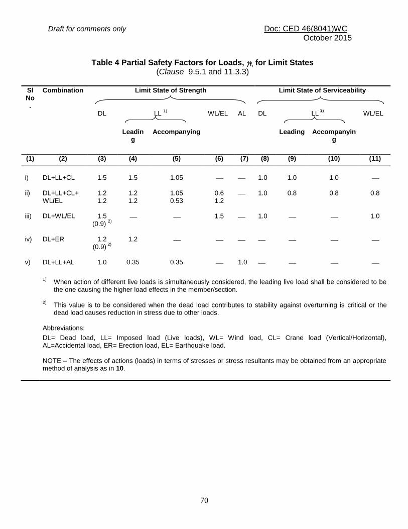
Draft for comments only Doc: CED 46(8041)WC October 2015
70
Table 4 Partial Safety Factors for Loads, f, for Limit States (Clause 9.5.1 and 11.3.3)
Sl No.
Combination
Limit State of Strength
Limit State of Serviceability
DL
LL 1)
WL/EL
AL
DL
LL 1)
WL/EL
Leadin
g
Accompanying
Leading
Accompanyin
g
(1) (2) (3) (4) (5) (6) (7) (8) (9) (10) (11)
i)
DL+LL+CL
1.5 1.5 1.05 1.0 1.0 1.0
ii) DL+LL+CL+ WL/EL
1.2 1.2
1.2 1.2
1.05 0.53
0.6 1.2
1.0 0.8 0.8 0.8
iii) DL+WL/EL 1.5 (0.9)
2)
1.5 1.0 1.0
iv) DL+ER 1.2
(0.9) 2)
1.2
v) DL+LL+AL 1.0 0.35 0.35 1.0
1) When action of different live loads is simultaneously considered, the leading live load shall be considered to be
the one causing the higher load effects in the member/section. 2)
This value is to be considered when the dead load contributes to stability against overturning is critical or the dead load causes reduction in stress due to other loads.
Abbreviations: DL= Dead load, LL= Imposed load (Live loads), WL= Wind load, CL= Crane load (Vertical/Horizontal), AL=Accidental load, ER= Erection load, EL= Earthquake load. NOTE – The effects of actions (loads) in terms of stresses or stress resultants may be obtained from an appropriate method of analysis as in 10.
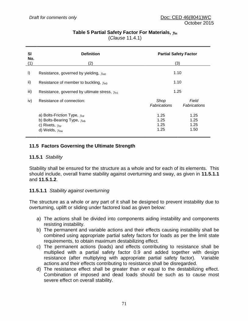
Draft for comments only Doc: CED 46(8041)WC October 2015
71
Table 5 Partial Safety Factor For Materials, m
(Clause 11.4.1)
Sl No. (1)
Definition
(2)
Partial Safety Factor
(3)
i)
Resistance, governed by yielding, m0
1.10
ii) Resistance of member to buckling, m0 1.10
iii) Resistance, governed by ultimate stress, m1 1.25
iv)
Resistance of connection:
a) Bolts-Friction Type, mf
b) Bolts-Bearing Type, mb
c) Rivets, mr
d) Welds, mw
Shop Fabrications
Field Fabrications
1.25 1.25 1.25 1.25
1.25 1.25 1.25 1.50
11.5 Factors Governing the Ultimate Strength 11.5.1 Stability Stability shall be ensured for the structure as a whole and for each of its elements. This should include, overall frame stability against overturning and sway, as given in 11.5.1.1 and 11.5.1.2. 11.5.1.1 Stability against overturning The structure as a whole or any part of it shall be designed to prevent instability due to overturning, uplift or sliding under factored load as given below:
a) The actions shall be divided into components aiding instability and components resisting instability.
b) The permanent and variable actions and their effects causing instability shall be combined using appropriate partial safety factors for loads as per the limit state requirements, to obtain maximum destabilizing effect.
c) The permanent actions (loads) and effects contributing to resistance shall be multiplied with a partial safety factor 0.9 and added together with design resistance (after multiplying with appropriate partial safety factor). Variable actions and their effects contributing to resistance shall be disregarded.
d) The resistance effect shall be greater than or equal to the destabilizing effect. Combination of imposed and dead loads should be such as to cause most severe effect on overall stability.

Draft for comments only Doc: CED 46(8041)WC October 2015
72
11.5.1.2 Sway stability The whole structure, including portions between expansion joints, shall be adequately stiff against sway. To ensure this, in addition to designing for applied horizontal loads, a separate check should be carried out for notional horizontal loads such as given in 10.3.6 to evaluate the sway under gravity loads. 11.5.2 Fatigue Generally fatigue need not be considered unless a structure or element is subjected to numerous significant fluctuations of stress. Stress changes due to fluctuations in wind loading normally need not be considered. Fatigue design shall be in accordance with
Section 6(m). When designing for fatigue, the partial safety factor for load, f, equal to unity shall be used for the load causing stress fluctuation and stress range. 11.5.3 Plastic Collapse Plastic analysis and design may be used, if the requirement specified under the plastic method of analysis (see 10.5) are satisfied. 11.6 Limit State of Serviceability Serviceability limit state is related to the criteria governing normal use. Serviceability limit state is limit state beyond which the service criteria specified below, are no longer met:
a) Deflection limit, b) Vibration limit, c) Durability consideration, and d) Fire resistance.
Unless specified otherwise, partial safety factor for loads, f, of value equal to unity shall be used for all loads leading to serviceability limit states to check the adequacy of the structure under serviceability limit states. 11.6.1 Deflection The deflection under serviceability loads of a building or a building component should not impair the strength of the structure or components or cause damage to finishings. Deflections are to be checked for the most adverse but realistic combination of service loads and their arrangement, by elastic analysis, using partial safety factors in Table 4. Table 6 gives recommended limits of deflections for certain structural members and systems. In Table 6, live load should include all post construction loads including superimposed dead loads. Circumstances may arise where greater or lesser values would be more appropriate, depending upon the nature of material in element to be

Draft for comments only Doc: CED 46(8041)WC October 2015
73
supported (vulnerable to cracking or not) and intended use of the structure, as required by client. 11.6.1.1 Where the deflection due to the combination of dead load and live load is likely to be excessive, consideration should be given to pre-camber the beams, trusses and girders. The value of desired camber shall be specified in design drawing. Generally, for spans greater than 25 m, a camber approximately equal to the deflection due to dead loads plus half the live load may be used. The deflection of a member shall be calculated without considering the impact factor or dynamic effect of the loads on deflection. Roofs, which are very flexible, shall be designed to withstand any additional load that is likely to occur as a result of ponding of water or accumulation of snow or ice. 11.6.2 Vibration Suitable provisions in the design shall be made for the dynamic effects of live loads, impact loads and vibration due to machinery operating loads. In severe cases possibility of resonance, fatigue or unacceptable vibrations shall be investigated. Unusually flexible structures (generally the height to effective width of lateral load resistance system exceeding 5:1) shall be investigated for lateral vibration under dynamic wind loads. Structures subjected to large number of cycles of loading shall be designed against fatigue failure, as specified in Section 6(m). Floor vibration effect shall be considered using specialist literature (see Annex B).
11.6.3 Durability Factors that affect the durability of the buildings, under conditions relevant to their intended life, are listed below:
a) Environment, b) Degree of exposure, c) Shape of the member and the structural detail, d) Protective measure, and e) Ease of maintenance.
11.6.3.1 The durability of steel structures shall be ensured by following recommendations in Section 6(o). Specialist literature may be referred to for more detailed and additional information in design for durability.

Draft for comments only Doc: CED 46(8041)WC October 2015
74
Table 6 Deflection Limits (Clause 11.6.1)
Type of Building
Deflectio
n
Design Load
Member
Supporting
Maximum Deflection
(1) (2) (3) (4) (5) (6)
I
ndustr
ial bu
ildin
gs
Vert
ical
Live load/ Wind load
Purlins and Girts
Elastic cladding
Span / 150 Span / 180 Brittle cladding
Live load
Simple span
Elastic cladding
Span / 240
Brittle cladding Span / 300
Live load
Cantilever span
Elastic cladding
Span / 120
Brittle cladding
Span / 150
Live load/ Wind load
Rafter supporting
Profiled Metal Sheeting
Span / 180
Plastered Sheeting Span / 240
Crane load (Manual operation)
Gantry
Crane
Span / 500
Crane load (Electric operation up to 50 t)
Gantry Crane Span / 750
Crane load (Electric operation over 50 t)
Gantry
Crane
Span / 1 000
L
ate
ral
No cranes
Column
Elastic cladding Height / 150
Masonry/Brittle cladding Height / 240
Crane + wind
Gantry (lateral)
Crane (absolute) Span / 400
Relative displacement between rails supporting crane
10 mm
Crane+ wind
Column/frame
Gantry (Elastic cladding; pendent operated)
Height / 200
Gantry (Brittle cladding; cab operated)
Height / 400
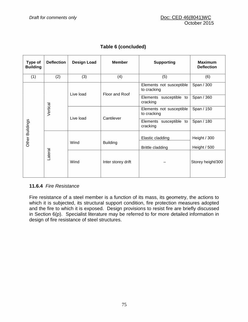
Draft for comments only Doc: CED 46(8041)WC October 2015
75
Table 6 (concluded)
Type of Building
Deflection
Design Load
Member
Supporting
Maximum Deflection
(1) (2) (3) (4) (5) (6)
O
ther
Build
ings
V
ert
ica
l
Live load
Floor and Roof
Elements not susceptible to cracking
Span / 300
Elements susceptible to cracking
Span / 360
Live load
Cantilever
Elements not susceptible to cracking
Span / 150
Elements susceptible to cracking
Span / 180
L
ate
ral
Wind
Building
Elastic cladding
Height / 300 Height / 500
Brittle cladding
Wind
Inter storey drift
–
Storey height/300
11.6.4 Fire Resistance Fire resistance of a steel member is a function of its mass, its geometry, the actions to which it is subjected, its structural support condition, fire protection measures adopted and the fire to which it is exposed. Design provisions to resist fire are briefly discussed in Section 6(p). Specialist literature may be referred to for more detailed information in design of fire resistance of steel structures.

Draft for comments only Doc: CED 46(8041)WC October 2015
76
SECTION 6(f) DESIGN OF TENSION MEMBERS
12 DESIGN OF TENSION MEMBERS 12.1 Tension Members Tension members are linear members in which axial forces act to cause elongation (stretch). Such members can sustain loads upto the ultimate load, at which stage they may fail by rupture at a critical section. However, if the gross area of the member yields over a major portion of its length before the rupture load is reached, the member may become non-functional due to excessive elongation. Plates and other rolled sections in tension may also fail by block shear of end bolted regions (see 12.4.1). The factored design tension T, in the members shall satisfy the following requirement:
T < Td
where Td = Design strength of the member The design strength of a member under axial tension, Td, is the lowest of the design strength due to yielding of gross section, Tdg; rupture strength of critical section, Tdn; and block shear Tdb, given in 12.2, 12.3 and 12.4, respectively. 12.2 Design Strength Due to Yielding of Gross Section The design strength of members under axial tension, Tdg, as governed by yielding of gross section, is given by
Tdg = Ag fy /m0
where fy = yield stress of the material,
Ag = gross area of cross-section, and
m0 = partial safety factor for failure in tension by yielding (see Table 5). 12.3 Design Strength Due to Rupture of Critical Section 12.3.1 Plates The design strength in tension of a plate, Tdn, as governed by rupture of net cross-sectional area, An, at the holes is given by
Tdn = 0.9 An fu / m1
where
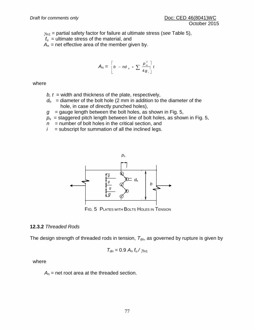
Draft for comments only Doc: CED 46(8041)WC October 2015
77
m1 = partial safety factor for failure at ultimate stress (see Table 5), fu = ultimate stress of the material, and An = net effective area of the member given by.
An = tg
pndb
i
2
si
h
4
where b, t = width and thickness of the plate, respectively, dh = diameter of the bolt hole (2 mm in addition to the diameter of the hole, in case of directly punched holes), g = gauge length between the bolt holes, as shown in Fig. 5, ps = staggered pitch length between line of bolt holes, as shown in Fig. 5, n = number of bolt holes in the critical section, and i = subscript for summation of all the inclined legs. 12.3.2 Threaded Rods The design strength of threaded rods in tension, Tdn, as governed by rupture is given by
Tdn = 0.9 An fu / m1
where
An = net root area at the threaded section.
ps
dh
b
g
g
g
g
FIG. 5 PLATES WITH BOLTS HOLES IN TENSION

Draft for comments only Doc: CED 46(8041)WC October 2015
78
12.3.3 Single Angles The rupture strength of an angle connected through one leg is affected by shear lag. The design strength, Tdn, as governed by rupture at net section is given by:
Tdn = 0.9 Anc fu / m1 + Ago fy /m0
where
= 1.4 – 0.076 (w/t) (fy/fu) (bs/Lc ) ≤ (0.9fum0/fym1) ≥ 0.7
where w = outstand leg width, bs = shear lag width, as shown in Fig. 6, and
Lc = length of the end connection, that is the distance between the outermost bolts in the end joint measured along the load direction or length of the weld along the load direction.
For preliminary sizing, the rupture strength of net section may be approximately taken as:
Tdn = An fu /m1
where
= 0.6 for one or two bolts, 0.7 for three bolts and 0.8 for four or more bolts along the length in the end connection or equivalent weld length, An = net area of the total cross-section, Anc= net area of the connected leg, Ago= gross area of the outstanding leg, and t = thickness of the leg.
w w
t
wl
bs = w + wl -t bs = w
FIG. 6 ANGLES WITH SINGLE LEG CONNECTIONS

Draft for comments only Doc: CED 46(8041)WC October 2015
79
12.3.4 Other Section The rupture strength, Tdn, of the double angles, channels, I-sections and other rolled steel sections, connected by one or more elements to an end gusset is also governed by shear lag effects. The design tensile strength of such sections as governed by
tearing of net section may also be calculated using equation in 12.3.3, where is calculated based on the shear lag distance, bs, taken from the farthest edge of the outstanding leg to the nearest bolt/weld line in the connected leg of the cross-section. 12.4 Design Strength Due to Block Shear The strength as governed by block shear at an end connection of plates and angles is calculated as given in 12.4.1. 12.4.1 Bolted Connections The block shear strength, Tdb of connection shall be taken as the smaller of,
Tdb = [ Avg fy /( 3 m0) + 0.9Atn fu /m1 ]
or
Tdb = [0.9Avn fu /( 3 m1) + Atg fy /m0]
where Avg , Avn = minimum gross and net area in shear along bolt line parallel to external force, respectively (1-2 and 3-4 as shown in Fig. 7a and 1-2 as shown in Fig. 7b), Atg , Atn = minimum gross and net area in tension from the bolt hole to the toe of the angle, end bolt line, perpendicular to the line of force, respectively (2-3 as shown in Fig. 7b), and fu , fy = ultimate and yield stress of the material, respectively.
1 2
4 3
FIG 7 BLOCK SHEAR FAILURE
CK SHEAR FAILURE
1 2
3 4
a Plate b Angle

Draft for comments only Doc: CED 46(8041)WC October 2015
80
12.4.2 Welded Connection The block shear strength, Tdb shall be checked for welded end connections by taking an appropriate section in the member around the end weld, which can shear off as a block.
SECTION 6 (g) DESIGN OF COMPRESSION MEMBERS 13 DESIGN OF COMPRESSION MEMBERS 13.1 Design Strength 13.1.1 Common hot rolled and built-up steel members used for carrying axial compression, usually fail by flexural buckling. The buckling strength of these members is affected by residual stresses, initial bow and accidental eccentricities of load. To account for all these factors, the strength of members subjected to axial compression is defined by buckling class a, b, c, or d as given Table 7. 13.1.2 The factored design compression, P in members shall satisfy the following requirement:
P < Pd
where Pd = Ae fcd
where Ae = Effective sectional area as defined in 13.3.2, and fcd = Design compressive stress, obtained as per 13.1.2.1. 13.1.2.1 The design compressive strength, fcd, of axially loaded compression members shall be calculated using the following equation:
m0ym0y0.5
22
m0y
cd//
/
ff
ff
where
= 0.5[1+ ( - 0.2)+ 2]
= non-dimensional effective slenderness ratio
= ccy
ff = Er
KLf2
2
y
fcc = Euler buckling stress =
2
2
/ rKL
E
where
KL/r = Effective slenderness ratio or ratio of effective length, KL to
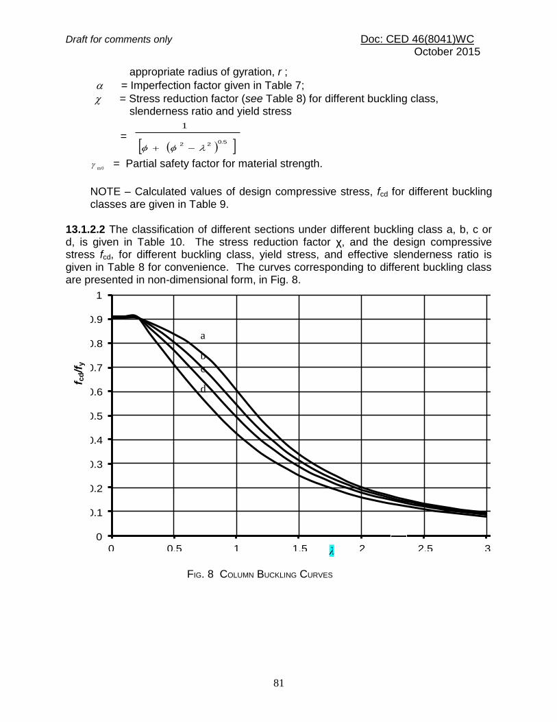
Draft for comments only Doc: CED 46(8041)WC October 2015
81
appropriate radius of gyration, r ;
= Imperfection factor given in Table 7;
= Stress reduction factor (see Table 8) for different buckling class, slenderness ratio and yield stress
= 0.522
1
m 0
= Partial safety factor for material strength.
NOTE – Calculated values of design compressive stress, fcd for different buckling classes are given in Table 9.
13.1.2.2 The classification of different sections under different buckling class a, b, c or d, is given in Table 10. The stress reduction factor χ, and the design compressive stress fcd, for different buckling class, yield stress, and effective slenderness ratio is given in Table 8 for convenience. The curves corresponding to different buckling class are presented in non-dimensional form, in Fig. 8.
0
0.1
0.2
0.3
0.4
0.5
0.6
0.7
0.8
0.9
1
0 0.5 1 1.5 2 2.5 3 3.5
fcd
/fy
Lamda
Buckling Curves
f cd/f
y
a
b
c
d
FIG. 8 COLUMN BUCKLING CURVES
λ

Draft for comments only Doc: CED 46(8041)WC October 2015
82
Table 7 Imperfection Factor, (Clause 13.1.1 and 13.1.2.1)
___________________________________________________________ Buckling Class
(1)
a
(2)
b
(3)
c
(4)
d
(5)
0.21
0.34
0.49
0.76
____________________________________________________________ 13.2 Effective Length of Compression Members 13.2.1 The effective length KL, is calculated from the actual length L, of the member, considering the rotational and relative translational boundary conditions at the ends. The actual length shall be taken as the length from center to center of its intersections with the supporting members in the plane of the buckling deformation. In the case of a member with a free end, the free standing length from the center of the intersecting member at the supported end, shall be taken as the actual length. 13.2.2 Effective Length Where the boundary conditions in the plane of buckling can be assessed, the effective length, KL can be calculated on the basis of Table 11. Where frame analysis does not consider the equilibrium of a framed structure in the deformed shape (second-order analysis or advanced analysis), the effective length of compression members in such cases can be calculated using the procedure given in C-1. The effective length of stepped column in single storey buildings can be calculated using the procedure given in C-2. 13.2.3 Eccentric Beam Connection In cases where the beam connections are eccentric in plan with respect to the axes of the column, the same conditions of restraint as in concentric connection shall be deemed to apply, provided the connections are carried across the flange or web of the columns as the case may be, and the web of the beam lies within, or in direct contact with the column section. Where practical difficulties prevent this, the effective length shall be taken as equal to the distance between points of restraint, in non-sway frames. 13.2.4 Compression Members in Trusses In the case of bolted, riveted or welded trusses and braced frames, the effective length, KL, of the compression members shall be taken as 0.7 to 1.0 times the distance between centers of connections, depending on the degree of end restraint provided. In the case of members of trusses, buckling in the plane perpendicular to the plane of the truss, the effective length, KL shall be taken as the distance between the centers of intersection. The design of angle struts shall be as specified in 13.5.

Draft for comments only Doc: CED 46(8041)WC October 2015
83
13.3 Design Details 13.3.1 Thickness of Plate Elements Classification of members on the basis of thickness of constituent plate elements shall satisfy the width-thickness ratio requirements specified in Table 2. 13.3.2 Effective Sectional Area, Ae Except as modified in 9.7.2 (Class 4), the gross sectional area shall be taken as the effective sectional area for all compression members fabricated by welding, bolting and riveting so long as the section is semi-compact or better. Holes not fitted with rivets, bolts or pins shall be deducted from gross area to calculate effective sectional area. 13.3.3 Eccentricity for Stanchions and Columns
13.3.3.1 For the purpose of determining the stress in a stanchion or column section, the beam reactions or similar loads shall be assumed to be applied at an eccentricity of 100 mm from the face of the section or at the center of bearing whichever dimension gives the greater eccentricity, and with the exception of the following two cases:
a) In the case of cap connection, the load shall be assumed to be applied at the face of the column or stanchion section or at the edge of packing, if used towards the span of the beam. b) In the case of a roof truss bearing on a cap, no eccentricity be taken for simple bearings without connections capable of developing any appreciable moment. In case of web member connection with face, actual eccentricity is to be considered.

Draft for comments only Doc: CED 46(8041)WC October 2015
84
Table 8(a) Stress Reduction Factor, for Column Buckling Class a (Clauses 13.1.2.1 and 13.1.2.2)
KL/r
Yield Stress, fy (MPa)
200 210 220 230 240 250 260 280 300 320 340 360 380 400 420 450 480 510 540
10 1.000 1.000 1.000 1.000 1.000 1.000 1.000 1.000 1.000 1.000 1.000 1.000 1.000 1.000 1.000 1.000 1.000 1.000 1.000
20 1.000 0.999 0.998 0.997 0.995 0.994 0.993 0.993 0.990 0.988 0.986 0.984 0.983 0.981 0.979 0.977 0.975 0.972 0.970
30 0.977 0.975 0.974 0.972 0.970 0.969 0.967 0.965 0.961 0.957 0.954 0.951 0.948 0.946 0.943 0.938 0.934 0.930 0.925
40 0.952 0.949 0.947 0.944 0.942 0.939 0.937 0.934 0.926 0.921 0.916 0.911 0.906 0.901 0.896 0.888 0.881 0.873 0.865
50 0.923 0.919 0.915 0.911 0.908 0.904 0.900 0.896 0.884 0.876 0.867 0.859 0.851 0.842 0.834 0.820 0.807 0.794 0.780
60 0.888 0.883 0.877 0.871 0.865 0.859 0.853 0.847 0.828 0.816 0.803 0.790 0.777 0.763 0.750 0.730 0.710 0.690 0.671
70 0.846 0.837 0.829 0.820 0.811 0.803 0.794 0.785 0.758 0.740 0.722 0.703 0.686 0.668 0.651 0.626 0.602 0.579 0.557
80 0.793 0.781 0.769 0.757 0.746 0.734 0.722 0.710 0.675 0.653 0.631 0.610 0.589 0.570 0.551 0.525 0.501 0.478 0.458
90 0.730 0.715 0.700 0.685 0.671 0.657 0.643 0.628 0.590 0.565 0.542 0.520 0.500 0.481 0.463 0.439 0.416 0.396 0.377
100 0.661 0.644 0.627 0.610 0.594 0.579 0.564 0.549 0.510 0.486 0.463 0.443 0.424 0.407 0.390 0.368 0.348 0.331 0.314
110 0.591 0.573 0.555 0.538 0.522 0.507 0.492 0.478 0.440 0.418 0.397 0.379 0.362 0.346 0.332 0.312 0.295 0.279 0.265
120 0.525 0.507 0.489 0.473 0.458 0.443 0.429 0.416 0.381 0.361 0.343 0.326 0.311 0.297 0.284 0.267 0.252 0.238 0.226
130 0.466 0.448 0.432 0.416 0.402 0.388 0.376 0.364 0.332 0.314 0.298 0.283 0.269 0.257 0.246 0.231 0.217 0.206 0.195
140 0.413 0.397 0.382 0.368 0.355 0.342 0.331 0.320 0.291 0.275 0.260 0.247 0.235 0.224 0.214 0.201 0.189 0.179 0.170
150 0.368 0.353 0.339 0.326 0.314 0.303 0.293 0.283 0.257 0.243 0.229 0.218 0.207 0.197 0.189 0.177 0.166 0.157 0.149
160 0.329 0.316 0.303 0.291 0.280 0.270 0.261 0.252 0.229 0.215 0.204 0.193 0.184 0.175 0.167 0.157 0.147 0.139 0.132
170 0.296 0.283 0.272 0.261 0.251 0.242 0.233 0.225 0.204 0.192 0.182 0.172 0.164 0.156 0.149 0.140 0.131 0.124 0.117
180 0.267 0.255 0.245 0.235 0.226 0.218 0.210 0.203 0.184 0.173 0.163 0.155 0.147 0.140 0.134 0.125 0.118 0.111 0.105
190 0.242 0.231 0.222 0.213 0.205 0.197 0.190 0.183 0.166 0.156 0.147 0.140 0.133 0.126 0.121 0.113 0.106 0.100 0.095
200 0.220 0.210 0.202 0.193 0.186 0.179 0.172 0.166 0.151 0.142 0.134 0.127 0.120 0.115 0.109 0.102 0.096 0.091 0.086
210 0.201 0.192 0.184 0.177 0.170 0.163 0.157 0.152 0.137 0.129 0.122 0.115 0.110 0.104 0.099 0.093 0.087 0.083 0.078
220 0.184 0.176 0.169 0.162 0.155 0.149 0.144 0.139 0.126 0.118 0.111 0.106 0.100 0.095 0.091 0.085 0.080 0.075 0.071
230 0.170 0.162 0.155 0.149 0.143 0.137 0.132 0.128 0.115 0.108 0.102 0.097 0.092 0.088 0.083 0.078 0.073 0.069 0.065
240 0.157 0.149 0.143 0.137 0.132 0.127 0.122 0.118 0.106 0.100 0.094 0.089 0.085 0.081 0.077 0.072 0.068 0.064 0.060
250 0.145 0.138 0.132 0.127 0.122 0.117 0.113 0.109 0.098 0.092 0.087 0.082 0.078 0.074 0.071 0.066 0.062 0.059 0.056
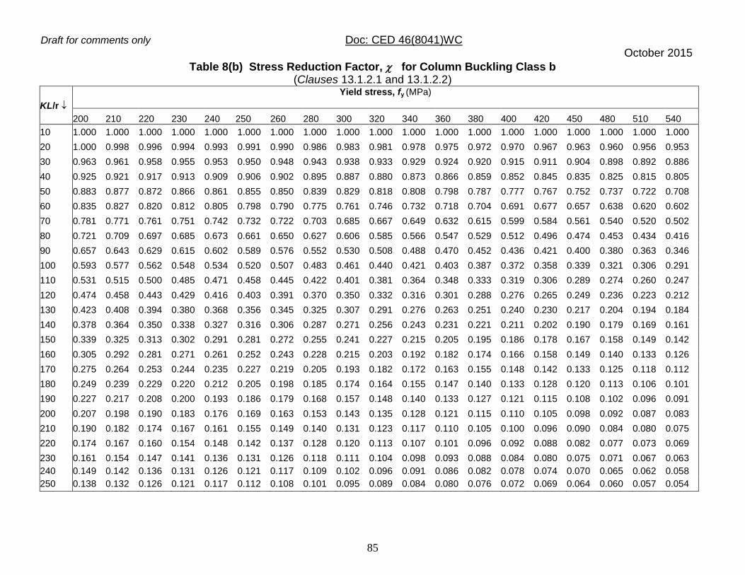
Draft for comments only Doc: CED 46(8041)WC October 2015
85
Table 8(b) Stress Reduction Factor, for Column Buckling Class b (Clauses 13.1.2.1 and 13.1.2.2)
KL/r
Yield stress, fy (MPa)
200 210 220 230 240 250 260 280 300 320 340 360 380 400 420 450 480 510 540
10 1.000 1.000 1.000 1.000 1.000 1.000 1.000 1.000 1.000 1.000 1.000 1.000 1.000 1.000 1.000 1.000 1.000 1.000 1.000
20 1.000 0.998 0.996 0.994 0.993 0.991 0.990 0.986 0.983 0.981 0.978 0.975 0.972 0.970 0.967 0.963 0.960 0.956 0.953
30 0.963 0.961 0.958 0.955 0.953 0.950 0.948 0.943 0.938 0.933 0.929 0.924 0.920 0.915 0.911 0.904 0.898 0.892 0.886
40 0.925 0.921 0.917 0.913 0.909 0.906 0.902 0.895 0.887 0.880 0.873 0.866 0.859 0.852 0.845 0.835 0.825 0.815 0.805
50 0.883 0.877 0.872 0.866 0.861 0.855 0.850 0.839 0.829 0.818 0.808 0.798 0.787 0.777 0.767 0.752 0.737 0.722 0.708
60 0.835 0.827 0.820 0.812 0.805 0.798 0.790 0.775 0.761 0.746 0.732 0.718 0.704 0.691 0.677 0.657 0.638 0.620 0.602
70 0.781 0.771 0.761 0.751 0.742 0.732 0.722 0.703 0.685 0.667 0.649 0.632 0.615 0.599 0.584 0.561 0.540 0.520 0.502
80 0.721 0.709 0.697 0.685 0.673 0.661 0.650 0.627 0.606 0.585 0.566 0.547 0.529 0.512 0.496 0.474 0.453 0.434 0.416
90 0.657 0.643 0.629 0.615 0.602 0.589 0.576 0.552 0.530 0.508 0.488 0.470 0.452 0.436 0.421 0.400 0.380 0.363 0.346
100 0.593 0.577 0.562 0.548 0.534 0.520 0.507 0.483 0.461 0.440 0.421 0.403 0.387 0.372 0.358 0.339 0.321 0.306 0.291
110 0.531 0.515 0.500 0.485 0.471 0.458 0.445 0.422 0.401 0.381 0.364 0.348 0.333 0.319 0.306 0.289 0.274 0.260 0.247
120 0.474 0.458 0.443 0.429 0.416 0.403 0.391 0.370 0.350 0.332 0.316 0.301 0.288 0.276 0.265 0.249 0.236 0.223 0.212
130 0.423 0.408 0.394 0.380 0.368 0.356 0.345 0.325 0.307 0.291 0.276 0.263 0.251 0.240 0.230 0.217 0.204 0.194 0.184
140 0.378 0.364 0.350 0.338 0.327 0.316 0.306 0.287 0.271 0.256 0.243 0.231 0.221 0.211 0.202 0.190 0.179 0.169 0.161
150 0.339 0.325 0.313 0.302 0.291 0.281 0.272 0.255 0.241 0.227 0.215 0.205 0.195 0.186 0.178 0.167 0.158 0.149 0.142
160 0.305 0.292 0.281 0.271 0.261 0.252 0.243 0.228 0.215 0.203 0.192 0.182 0.174 0.166 0.158 0.149 0.140 0.133 0.126
170 0.275 0.264 0.253 0.244 0.235 0.227 0.219 0.205 0.193 0.182 0.172 0.163 0.155 0.148 0.142 0.133 0.125 0.118 0.112
180 0.249 0.239 0.229 0.220 0.212 0.205 0.198 0.185 0.174 0.164 0.155 0.147 0.140 0.133 0.128 0.120 0.113 0.106 0.101
190 0.227 0.217 0.208 0.200 0.193 0.186 0.179 0.168 0.157 0.148 0.140 0.133 0.127 0.121 0.115 0.108 0.102 0.096 0.091
200 0.207 0.198 0.190 0.183 0.176 0.169 0.163 0.153 0.143 0.135 0.128 0.121 0.115 0.110 0.105 0.098 0.092 0.087 0.083
210 0.190 0.182 0.174 0.167 0.161 0.155 0.149 0.140 0.131 0.123 0.117 0.110 0.105 0.100 0.096 0.090 0.084 0.080 0.075
220 0.174 0.167 0.160 0.154 0.148 0.142 0.137 0.128 0.120 0.113 0.107 0.101 0.096 0.092 0.088 0.082 0.077 0.073 0.069
230 0.161 0.154 0.147 0.141 0.136 0.131 0.126 0.118 0.111 0.104 0.098 0.093 0.088 0.084 0.080 0.075 0.071 0.067 0.063
240 0.149 0.142 0.136 0.131 0.126 0.121 0.117 0.109 0.102 0.096 0.091 0.086 0.082 0.078 0.074 0.070 0.065 0.062 0.058
250 0.138 0.132 0.126 0.121 0.117 0.112 0.108 0.101 0.095 0.089 0.084 0.080 0.076 0.072 0.069 0.064 0.060 0.057 0.054
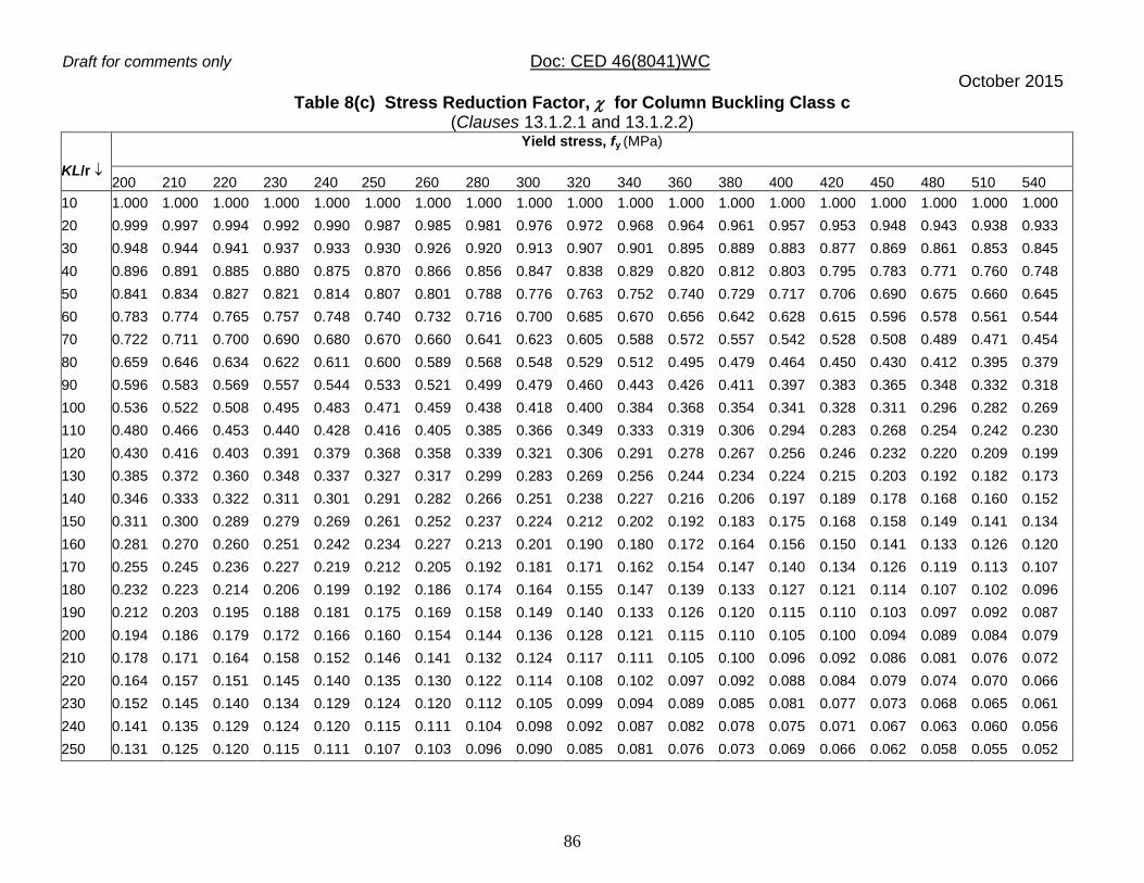
Draft for comments only Doc: CED 46(8041)WC October 2015
86
Table 8(c) Stress Reduction Factor, for Column Buckling Class c (Clauses 13.1.2.1 and 13.1.2.2)
KL/r
Yield stress, fy (MPa)
200 210 220 230 240 250 260 280 300 320 340 360 380 400 420 450 480 510 540
10 1.000 1.000 1.000 1.000 1.000 1.000 1.000 1.000 1.000 1.000 1.000 1.000 1.000 1.000 1.000 1.000 1.000 1.000 1.000
20 0.999 0.997 0.994 0.992 0.990 0.987 0.985 0.981 0.976 0.972 0.968 0.964 0.961 0.957 0.953 0.948 0.943 0.938 0.933
30 0.948 0.944 0.941 0.937 0.933 0.930 0.926 0.920 0.913 0.907 0.901 0.895 0.889 0.883 0.877 0.869 0.861 0.853 0.845
40 0.896 0.891 0.885 0.880 0.875 0.870 0.866 0.856 0.847 0.838 0.829 0.820 0.812 0.803 0.795 0.783 0.771 0.760 0.748
50 0.841 0.834 0.827 0.821 0.814 0.807 0.801 0.788 0.776 0.763 0.752 0.740 0.729 0.717 0.706 0.690 0.675 0.660 0.645
60 0.783 0.774 0.765 0.757 0.748 0.740 0.732 0.716 0.700 0.685 0.670 0.656 0.642 0.628 0.615 0.596 0.578 0.561 0.544
70 0.722 0.711 0.700 0.690 0.680 0.670 0.660 0.641 0.623 0.605 0.588 0.572 0.557 0.542 0.528 0.508 0.489 0.471 0.454
80 0.659 0.646 0.634 0.622 0.611 0.600 0.589 0.568 0.548 0.529 0.512 0.495 0.479 0.464 0.450 0.430 0.412 0.395 0.379
90 0.596 0.583 0.569 0.557 0.544 0.533 0.521 0.499 0.479 0.460 0.443 0.426 0.411 0.397 0.383 0.365 0.348 0.332 0.318
100 0.536 0.522 0.508 0.495 0.483 0.471 0.459 0.438 0.418 0.400 0.384 0.368 0.354 0.341 0.328 0.311 0.296 0.282 0.269
110 0.480 0.466 0.453 0.440 0.428 0.416 0.405 0.385 0.366 0.349 0.333 0.319 0.306 0.294 0.283 0.268 0.254 0.242 0.230
120 0.430 0.416 0.403 0.391 0.379 0.368 0.358 0.339 0.321 0.306 0.291 0.278 0.267 0.256 0.246 0.232 0.220 0.209 0.199
130 0.385 0.372 0.360 0.348 0.337 0.327 0.317 0.299 0.283 0.269 0.256 0.244 0.234 0.224 0.215 0.203 0.192 0.182 0.173
140 0.346 0.333 0.322 0.311 0.301 0.291 0.282 0.266 0.251 0.238 0.227 0.216 0.206 0.197 0.189 0.178 0.168 0.160 0.152
150 0.311 0.300 0.289 0.279 0.269 0.261 0.252 0.237 0.224 0.212 0.202 0.192 0.183 0.175 0.168 0.158 0.149 0.141 0.134
160 0.281 0.270 0.260 0.251 0.242 0.234 0.227 0.213 0.201 0.190 0.180 0.172 0.164 0.156 0.150 0.141 0.133 0.126 0.120
170 0.255 0.245 0.236 0.227 0.219 0.212 0.205 0.192 0.181 0.171 0.162 0.154 0.147 0.140 0.134 0.126 0.119 0.113 0.107
180 0.232 0.223 0.214 0.206 0.199 0.192 0.186 0.174 0.164 0.155 0.147 0.139 0.133 0.127 0.121 0.114 0.107 0.102 0.096
190 0.212 0.203 0.195 0.188 0.181 0.175 0.169 0.158 0.149 0.140 0.133 0.126 0.120 0.115 0.110 0.103 0.097 0.092 0.087
200 0.194 0.186 0.179 0.172 0.166 0.160 0.154 0.144 0.136 0.128 0.121 0.115 0.110 0.105 0.100 0.094 0.089 0.084 0.079
210 0.178 0.171 0.164 0.158 0.152 0.146 0.141 0.132 0.124 0.117 0.111 0.105 0.100 0.096 0.092 0.086 0.081 0.076 0.072
220 0.164 0.157 0.151 0.145 0.140 0.135 0.130 0.122 0.114 0.108 0.102 0.097 0.092 0.088 0.084 0.079 0.074 0.070 0.066
230 0.152 0.145 0.140 0.134 0.129 0.124 0.120 0.112 0.105 0.099 0.094 0.089 0.085 0.081 0.077 0.073 0.068 0.065 0.061
240 0.141 0.135 0.129 0.124 0.120 0.115 0.111 0.104 0.098 0.092 0.087 0.082 0.078 0.075 0.071 0.067 0.063 0.060 0.056
250 0.131 0.125 0.120 0.115 0.111 0.107 0.103 0.096 0.090 0.085 0.081 0.076 0.073 0.069 0.066 0.062 0.058 0.055 0.052
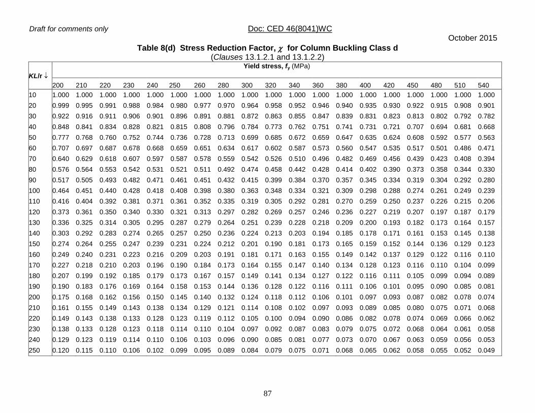
Draft for comments only Doc: CED 46(8041)WC October 2015
87
Table 8(d) Stress Reduction Factor, for Column Buckling Class d (Clauses 13.1.2.1 and 13.1.2.2)
KL/r
Yield stress, fy (MPa)
200 210 220 230 240 250 260 280 300 320 340 360 380 400 420 450 480 510 540
10 1.000 1.000 1.000 1.000 1.000 1.000 1.000 1.000 1.000 1.000 1.000 1.000 1.000 1.000 1.000 1.000 1.000 1.000 1.000
20 0.999 0.995 0.991 0.988 0.984 0.980 0.977 0.970 0.964 0.958 0.952 0.946 0.940 0.935 0.930 0.922 0.915 0.908 0.901
30 0.922 0.916 0.911 0.906 0.901 0.896 0.891 0.881 0.872 0.863 0.855 0.847 0.839 0.831 0.823 0.813 0.802 0.792 0.782
40 0.848 0.841 0.834 0.828 0.821 0.815 0.808 0.796 0.784 0.773 0.762 0.751 0.741 0.731 0.721 0.707 0.694 0.681 0.668
50 0.777 0.768 0.760 0.752 0.744 0.736 0.728 0.713 0.699 0.685 0.672 0.659 0.647 0.635 0.624 0.608 0.592 0.577 0.563
60 0.707 0.697 0.687 0.678 0.668 0.659 0.651 0.634 0.617 0.602 0.587 0.573 0.560 0.547 0.535 0.517 0.501 0.486 0.471
70 0.640 0.629 0.618 0.607 0.597 0.587 0.578 0.559 0.542 0.526 0.510 0.496 0.482 0.469 0.456 0.439 0.423 0.408 0.394
80 0.576 0.564 0.553 0.542 0.531 0.521 0.511 0.492 0.474 0.458 0.442 0.428 0.414 0.402 0.390 0.373 0.358 0.344 0.330
90 0.517 0.505 0.493 0.482 0.471 0.461 0.451 0.432 0.415 0.399 0.384 0.370 0.357 0.345 0.334 0.319 0.304 0.292 0.280
100 0.464 0.451 0.440 0.428 0.418 0.408 0.398 0.380 0.363 0.348 0.334 0.321 0.309 0.298 0.288 0.274 0.261 0.249 0.239
110 0.416 0.404 0.392 0.381 0.371 0.361 0.352 0.335 0.319 0.305 0.292 0.281 0.270 0.259 0.250 0.237 0.226 0.215 0.206
120 0.373 0.361 0.350 0.340 0.330 0.321 0.313 0.297 0.282 0.269 0.257 0.246 0.236 0.227 0.219 0.207 0.197 0.187 0.179
130 0.336 0.325 0.314 0.305 0.295 0.287 0.279 0.264 0.251 0.239 0.228 0.218 0.209 0.200 0.193 0.182 0.173 0.164 0.157
140 0.303 0.292 0.283 0.274 0.265 0.257 0.250 0.236 0.224 0.213 0.203 0.194 0.185 0.178 0.171 0.161 0.153 0.145 0.138
150 0.274 0.264 0.255 0.247 0.239 0.231 0.224 0.212 0.201 0.190 0.181 0.173 0.165 0.159 0.152 0.144 0.136 0.129 0.123
160 0.249 0.240 0.231 0.223 0.216 0.209 0.203 0.191 0.181 0.171 0.163 0.155 0.149 0.142 0.137 0.129 0.122 0.116 0.110
170 0.227 0.218 0.210 0.203 0.196 0.190 0.184 0.173 0.164 0.155 0.147 0.140 0.134 0.128 0.123 0.116 0.110 0.104 0.099
180 0.207 0.199 0.192 0.185 0.179 0.173 0.167 0.157 0.149 0.141 0.134 0.127 0.122 0.116 0.111 0.105 0.099 0.094 0.089
190 0.190 0.183 0.176 0.169 0.164 0.158 0.153 0.144 0.136 0.128 0.122 0.116 0.111 0.106 0.101 0.095 0.090 0.085 0.081
200 0.175 0.168 0.162 0.156 0.150 0.145 0.140 0.132 0.124 0.118 0.112 0.106 0.101 0.097 0.093 0.087 0.082 0.078 0.074
210 0.161 0.155 0.149 0.143 0.138 0.134 0.129 0.121 0.114 0.108 0.102 0.097 0.093 0.089 0.085 0.080 0.075 0.071 0.068
220 0.149 0.143 0.138 0.133 0.128 0.123 0.119 0.112 0.105 0.100 0.094 0.090 0.086 0.082 0.078 0.074 0.069 0.066 0.062
230 0.138 0.133 0.128 0.123 0.118 0.114 0.110 0.104 0.097 0.092 0.087 0.083 0.079 0.075 0.072 0.068 0.064 0.061 0.058
240 0.129 0.123 0.119 0.114 0.110 0.106 0.103 0.096 0.090 0.085 0.081 0.077 0.073 0.070 0.067 0.063 0.059 0.056 0.053
250 0.120 0.115 0.110 0.106 0.102 0.099 0.095 0.089 0.084 0.079 0.075 0.071 0.068 0.065 0.062 0.058 0.055 0.052 0.049

Draft for comments only Doc: CED 46(8041)WC October 2015
88
Table 9(a) Design Compressive Stress, fcd (MPa) For Column Buckling Class a (Clauses 13.1.2.1 and 13.1.2.2)
KL/r
Yield stress, fy (MPa)
200 210 220 230 240 250 260 280 300 320 340 360 380 400 420 450 480 510 540
10 182 191 200 213 218 227 236 255 273 291 309 327 345 364 382 409 436 464 491
20 182 191 200 208 217 226 235 252 270 287 305 322 339 357 374 400 425 451 476
30 178 186 195 203 212 220 229 245 262 279 295 311 328 344 360 384 408 431 454
40 173 181 189 197 205 213 221 237 253 268 283 298 313 328 342 363 384 405 425
50 168 176 183 191 198 205 213 227 241 255 268 281 294 306 318 336 352 368 383
60 162 169 175 182 189 195 202 214 226 237 248 258 268 278 286 299 310 320 329
70 154 160 166 171 177 182 188 197 207 215 223 230 237 243 249 256 263 268 274
80 144 149 154 158 163 167 171 178 184 190 195 199 204 207 210 215 219 222 225
90 133 137 140 143 146 149 152 157 161 164 168 170 173 175 177 179 182 184 185
100 120 123 125 128 130 132 133 136 139 141 143 145 146 148 149 151 152 153 154
110 107 109 111 112 114 115 116 118 120 121 123 124 125 126 127 128 129 129 130
120 95.5 96.7 97.9 98.9 100 101 101 103 104 105 106 107 107 108 109 109 110 110 111
130 84.6 85.5 86.3 87 87.7 88.3 88.8 89.8 90.6 91.3 92.0 92.5 93.0 93.5 93.9 94.4 94.9 95.3 95.7
140 75.2 75.8 76.4 76.9 77.4 77.8 78.2 78.9 79.5 80.0 80.5 80.9 81.3 81.6 81.9 82.3 82.6 83.0 83.2
150 67.0 67.4 67.9 68.2 68.6 68.9 69.2 69.7 70.2 70.6 70.9 71.2 71.5 71.8 72.0 72.3 72.6 72.9 73.1
160 59.9 60.3 60.6 60.9 61.1 61.4 61.6 62.0 62.4 62.7 62.9 63.2 63.4 63.6 63.8 64.0 64.3 64.5 64.6
170 53.8 54.1 54.3 54.6 54.8 55.0 55.1 55.5 55.7 56.0 56.2 56.4 56.6 56.7 56.9 57.1 57.3 57.4 57.6
180 48.6 48.8 49.0 49.2 49.3 49.5 49.6 49.9 50.1 50.3 50.5 50.6 50.8 50.9 51.0 51.2 51.3 51.5 51.6
190 44.0 44.2 44.3 44.5 44.6 44.7 44.9 45.1 45.3 45.4 45.6 45.7 45.8 45.9 46.0 46.2 46.3 46.4 46.5
200 40.0 40.2 40.3 40.4 40.5 40.7 40.7 40.9 41.1 41.2 41.3 41.4 41.5 41.6 41.7 41.8 41.9 42.0 42.1
210 36.6 36.7 36.8 36.9 37.0 37.1 37.2 37.3 37.4 37.6 37.7 37.8 37.8 37.9 38.0 38.1 38.2 38.3 38.3
220 33.5 33.6 33.7 33.8 33.9 34.0 34.0 34.2 34.3 34.4 34.5 34.5 34.6 34.7 34.7 34.8 34.9 35.0 35.0
230 30.8 30.9 31.0 31.1 31.2 31.2 31.3 31.4 31.5 31.6 31.6 31.7 31.8 31.8 31.9 31.9 32.0 32.1 32.1
240 28.5 28.5 28.6 28.7 28.7 28.8 28.8 28.9 29.0 29.1 29.1 29.2 29.3 29.3 29.4 29.4 29.5 29.5 29.6
250 26.3 26.4 26.5 26.5 26.6 26.6 26.7 26.7 26.8 26.9 26.9 27.0 27.0 27.1 27.1 27.2 27.2 27.3 27.3

Draft for comments only Doc: CED 46(8041)WC October 2015
89
Table 9(b) Design Compressive Stress, fcd (MPa) for Column Buckling Class b (Clauses 13.1.2.1 and 13.1.2.2)
KL/r
Yield stress, fy (MPa)
200 210 220 230 240 250 260 280 300 320 340 360 380 400 420 450 480 510 540
10 182 191 200 209 218 227 236 255 273 291 309 327 345 364 382 409 436 464 491
20 182 190 199 208 217 225 234 251 268 285 302 319 336 353 369 394 419 443 468
30 175 183 192 200 208 216 224 240 256 271 287 302 318 333 348 370 392 414 435
40 168 176 183 191 198 206 213 228 242 256 270 283 297 310 323 342 360 378 395
50 161 167 174 181 188 194 201 214 226 238 250 261 272 283 293 308 322 335 347
60 152 158 164 170 176 181 187 197 207 217 226 235 243 251 259 269 279 287 295
70 142 147 152 157 162 166 171 179 187 194 201 207 213 218 223 230 236 241 246
80 131 135 139 143 147 150 154 160 165 170 175 179 183 186 190 194 198 201 204
90 120 123 126 129 131 134 136 141 144 148 151 154 156 159 161 163 166 168 170
100 108 110 112 114 116 118 120 123 126 128 130 132 134 135 137 139 140 142 143
110 96.5 98.3 100 101 103 104 105 107 109 111 112 114 115 116 117 118 119 121 121
120 86.2 87.5 88.6 89.7 90.7 91.7 92.5 94.1 95.4 96.6 97.7 98.6 100 100 101 102 103 104 104
130 76.9 77.8 78.7 79.5 80.3 81.0 81.6 82.7 83.7 84.6 85.4 86.1 86.8 87.3 87.9 88.6 89.2 89.8 90.3
140 68.7 69.4 70.1 70.7 71.3 71.8 72.3 73.1 73.9 74.6 75.2 75.7 76.2 76.6 77.1 77.6 78.1 78.5 78.9
150 61.6 62.1 62.6 63.1 63.6 64.0 64.3 65.0 65.6 66.1 66.6 67.0 67.4 67.7 68.1 68.5 68.9 69.2 69.5
160 55.4 55.8 56.2 56.6 56.9 57.3 57.5 58.1 58.5 59.0 59.3 59.7 60.0 60.3 60.5 60.9 61.2 61.5 61.7
170 50.0 50.3 50.7 51.0 51.2 51.5 51.7 52.2 52.5 52.9 53.2 53.5 53.7 53.9 54.1 54.4 54.7 54.9 55.1
180 45.3 45.6 45.9 46.1 46.3 46.5 46.7 47.1 47.4 47.7 47.9 48.1 48.3 48.5 48.7 48.9 49.2 49.3 49.5
190 41.2 41.5 41.7 41.9 42.1 42.2 42.4 42.7 42.9 43.2 43.4 43.6 43.7 43.9 44.0 44.2 44.4 44.6 44.7
200 37.6 37.8 38.0 38.2 38.3 38.5 38.6 38.9 39.1 39.3 39.5 39.6 39.8 39.9 40.0 40.2 40.3 40.5 40.6
210 34.5 34.7 34.8 35.0 35.1 35.2 35.3 35.5 35.7 35.9 36.0 36.2 36.3 36.4 36.5 36.6 36.8 36.9 37.0
220 31.7 31.9 32.0 32.1 32.2 32.3 32.4 32.6 32.8 32.9 33.0 33.1 33.2 33.3 33.4 33.6 33.7 33.8 33.9
230 29.2 29.4 29.5 29.6 29.7 29.8 29.9 30.0 30.1 30.3 30.4 30.5 30.6 30.7 30.7 30.8 30.9 31.0 31.1
240 27.1 27.2 27.3 27.3 27.4 27.5 27.6 27.7 27.8 27.9 28.0 28.1 28.2 28.3 28.3 28.4 28.5 28.6 28.7
250 25.1 25.2 25.3 25.3 25.4 25.5 25.6 25.7 25.8 25.9 26.0 26.0 26.1 26.2 26.2 26.3 26.4 26.5 26.5

Draft for comments only Doc: CED 46(8041)WC October 2015
90
Table 9(c) Design Compressive Stress, fcd (MPa) for Column Buckling Class c (Clauses 13.1.2.1 and 13.1.2.2)
KL/r
Yield stress, fy, (MPa)
200 210 220 230 240 250 260 280 300 320 340 360 380 400 420 450 480 510 540
10 182 191 200 209 218 227 236 255 273 291 309 327 345 364 382 409 436 464 491
20 182 190 199 207 216 224 233 250 266 283 299 316 332 348 364 388 412 435 458
30 172 180 188 196 204 211 219 234 249 264 278 293 307 321 335 355 376 395 415
40 163 170 177 184 191 198 205 218 231 244 256 268 280 292 304 320 337 352 367
50 153 159 165 172 178 183 189 201 212 222 232 242 252 261 270 282 295 306 317
60 142 148 153 158 163 168 173 182 191 199 207 215 222 228 235 244 252 260 267
70 131 136 140 144 148 152 156 163 170 176 182 187 192 197 202 208 213 218 223
80 120 123 127 130 133 136 139 145 149 154 158 162 165 169 172 176 180 183 186
90 108 111 114 116 119 121 123 127 131 134 137 140 142 144 146 149 152 154 156
100 97.5 100 102 104 105 107 109 112 114 116 119 120 122 124 125 127 129 131 132
110 87.3 89.0 90.5 92.0 93.3 94.6 95.7 97.9 100 102 103 104 106 107 108 110 111 112 113
120 78.2 79.4 80.6 81.7 82.7 83.7 84.6 86.2 87.6 88.9 90.1 91.1 92.1 93.0 93.8 94.9 95.9 96.8 97.6
130 70.0 71.0 71.9 72.8 73.5 74.3 75.0 76.2 77.3 78.3 79.2 80.0 80.7 81.4 82.0 82.9 83.6 84.3 84.9
140 62.9 63.6 64.4 65.0 65.6 66.2 66.7 67.7 68.6 69.3 70.0 70.7 71.2 71.8 72.3 72.9 73.5 74.1 74.6
150 56.6 57.2 57.8 58.3 58.8 59.2 59.7 60.4 61.1 61.7 62.3 62.8 63.3 63.7 64.1 64.6 65.1 65.5 65.9
160 51.1 51.6 52.1 52.5 52.9 53.3 53.6 54.2 54.8 55.3 55.7 56.1 56.5 56.9 57.2 57.6 58.0 58.4 58.7
170 46.4 46.8 47.1 47.5 47.8 48.1 48.4 48.9 49.3 49.8 50.1 50.5 50.8 51.1 51.3 51.7 52.0 52.3 52.6
180 42.2 42.5 42.8 43.1 43.4 43.6 43.9 44.3 44.7 45.0 45.3 45.6 45.8 46.1 46.3 46.6 46.9 47.1 47.3
190 38.5 38.8 39.0 39.3 39.5 39.7 39.9 40.3 40.6 40.9 41.1 41.4 41.6 41.8 42.0 42.2 42.5 42.7 42.9
200 35.3 35.5 35.7 35.9 36.1 36.3 36.5 36.8 37.0 37.3 37.5 37.7 37.9 38.1 38.2 38.4 38.6 38.8 39.0
210 32.4 32.6 32.8 33.0 33.1 33.3 33.4 33.7 33.9 34.1 34.3 34.5 34.7 34.8 34.9 35.1 35.3 35.4 35.6
220 29.9 30.1 30.2 30.4 30.5 30.6 30.8 31.0 31.2 31.4 31.5 31.7 31.8 31.9 32.1 32.2 32.4 32.5 32.6
230 27.6 27.8 27.9 28.0 28.2 28.3 28.4 28.6 28.8 28.9 29.1 29.2 29.3 29.4 29.5 29.7 29.8 29.9 30.0
240 25.6 25.7 25.9 26.0 26.1 26.2 26.3 26.4 26.6 26.7 26.9 27.0 27.1 27.2 27.3 27.4 27.5 27.6 27.7
250 23.8 23.9 24.0 24.1 24.2 24.3 24.4 24.5 24.7 24.8 24.9 25.0 25.1 25.2 25.3 25.4 25.5 25.6 25.7
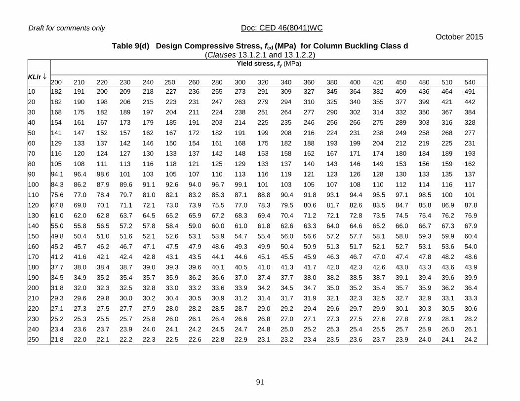
Draft for comments only Doc: CED 46(8041)WC October 2015
91
Table 9(d) Design Compressive Stress, fcd (MPa) for Column Buckling Class d (Clauses 13.1.2.1 and 13.1.2.2)
KL/r
Yield stress, fy (MPa)
200 210 220 230 240 250 260 280 300 320 340 360 380 400 420 450 480 510 540
10 182 191 200 209 218 227 236 255 273 291 309 327 345 364 382 409 436 464 491
20 182 190 198 206 215 223 231 247 263 279 294 310 325 340 355 377 399 421 442
30 168 175 182 189 197 204 211 224 238 251 264 277 290 302 314 332 350 367 384
40 154 161 167 173 179 185 191 203 214 225 235 246 256 266 275 289 303 316 328
50 141 147 152 157 162 167 172 182 191 199 208 216 224 231 238 249 258 268 277
60 129 133 137 142 146 150 154 161 168 175 182 188 193 199 204 212 219 225 231
70 116 120 124 127 130 133 137 142 148 153 158 162 167 171 174 180 184 189 193
80 105 108 111 113 116 118 121 125 129 133 137 140 143 146 149 153 156 159 162
90 94.1 96.4 98.6 101 103 105 107 110 113 116 119 121 123 126 128 130 133 135 137
100 84.3 86.2 87.9 89.6 91.1 92.6 94.0 96.7 99.1 101 103 105 107 108 110 112 114 116 117
110 75.6 77.0 78.4 79.7 81.0 82.1 83.2 85.3 87.1 88.8 90.4 91.8 93.1 94.4 95.5 97.1 98.5 100 101
120 67.8 69.0 70.1 71.1 72.1 73.0 73.9 75.5 77.0 78.3 79.5 80.6 81.7 82.6 83.5 84.7 85.8 86.9 87.8
130 61.0 62.0 62.8 63.7 64.5 65.2 65.9 67.2 68.3 69.4 70.4 71.2 72.1 72.8 73.5 74.5 75.4 76.2 76.9
140 55.0 55.8 56.5 57.2 57.8 58.4 59.0 60.0 61.0 61.8 62.6 63.3 64.0 64.6 65.2 66.0 66.7 67.3 67.9
150 49.8 50.4 51.0 51.6 52.1 52.6 53.1 53.9 54.7 55.4 56.0 56.6 57.2 57.7 58.1 58.8 59.3 59.9 60.4
160 45.2 45.7 46.2 46.7 47.1 47.5 47.9 48.6 49.3 49.9 50.4 50.9 51.3 51.7 52.1 52.7 53.1 53.6 54.0
170 41.2 41.6 42.1 42.4 42.8 43.1 43.5 44.1 44.6 45.1 45.5 45.9 46.3 46.7 47.0 47.4 47.8 48.2 48.6
180 37.7 38.0 38.4 38.7 39.0 39.3 39.6 40.1 40.5 41.0 41.3 41.7 42.0 42.3 42.6 43.0 43.3 43.6 43.9
190 34.5 34.9 35.2 35.4 35.7 35.9 36.2 36.6 37.0 37.4 37.7 38.0 38.2 38.5 38.7 39.1 39.4 39.6 39.9
200 31.8 32.0 32.3 32.5 32.8 33.0 33.2 33.6 33.9 34.2 34.5 34.7 35.0 35.2 35.4 35.7 35.9 36.2 36.4
210 29.3 29.6 29.8 30.0 30.2 30.4 30.5 30.9 31.2 31.4 31.7 31.9 32.1 32.3 32.5 32.7 32.9 33.1 33.3
220 27.1 27.3 27.5 27.7 27.9 28.0 28.2 28.5 28.7 29.0 29.2 29.4 29.6 29.7 29.9 30.1 30.3 30.5 30.6
230 25.2 25.3 25.5 25.7 25.8 26.0 26.1 26.4 26.6 26.8 27.0 27.1 27.3 27.5 27.6 27.8 27.9 28.1 28.2
240 23.4 23.6 23.7 23.9 24.0 24.1 24.2 24.5 24.7 24.8 25.0 25.2 25.3 25.4 25.5 25.7 25.9 26.0 26.1
250 21.8 22.0 22.1 22.2 22.3 22.5 22.6 22.8 22.9 23.1 23.2 23.4 23.5 23.6 23.7 23.9 24.0 24.1 24.2

Draft for comments only Doc: CED 46(8041)WC October 2015
92
Table 10 Buckling Class of Cross-Sections (Clause 13.1.2.2)
________________________________________________________________ Cross-Section Limits Buckling
About Axis Buckling Class
(1) (2) (3) (4)
Rolled I-Sections h/bf > 1.2 :
tf 40 mm
40mm < tf 100 mm
z-z y-y
z-z y-y
a b b c
h/bf < 1.2 :
tf 100 mm tf >100 mm
z-z y-y
z-z y-y
b c d d
Welded I-Section
tf <40 mm tf >40 mm
z-z y-y
z-z y-y
b c c d
Hollow Section
Hot rolled Any a
Cold formed Any b
Welded Box Section
Generally (except as below) Any b
Thick welds and b/tf < 30 h/tw < 30
z-z
y-y
c c
Channel, Angle, T and Solid Sections
Any
b
y
d
h tw
bf
y
z z
tf
h
y
tw
t
f tf
y
b
z z h
y
tw
t
f tf
y
b
z z
y
tw
y
z
z
b
tf
h
y
y
z z

Draft for comments only Doc: CED 46(8041)WC October 2015
93
Built-up Member
Any
c
________________________________________________________________
y
y
z z

Draft for comments only Doc: CED 46(8041)WC October 2015
94
Table 11 Effective Length of Prismatic Compression Members (Clause 13.2.2)
Boundary Conditions
Schematic
Representation
(5)
Effective Length
(6)
At one end
At the other end
Translation (1)
Rotation (2)
Translation (3)
Rotation (4)
Restrained Restrained Free Free
2.0L
Restrained Free Free Restrained
Restrained
Free Restrained Free
1.0L
Restrained Restrained Free Restrained
1.2L
Restrained Restrained Restrained Free
0.8L
Restrained Restrained Restrained Restrained
0.65L
Draft for comments only Doc: CED 46(8041)WC October 2015
95
NOTE – L is the unsupported length of the compression member (see 13.2.1).
13.3.3.2 In continuous columns, the bending moments due to eccentricities of loading on the columns at any floor may be divided equally between the columns above and below that floor level, provided that the moment of inertia of one column section, divided by its effective length does not exceed 1.5 times the corresponding value of the other column. Where this ratio is exceeded, the bending moment shall be divided in proportion to the moment of inertia of the column sections divided by their respective effective lengths.
13.3.4 Splices 13.3.4.1 Where the ends of compression members are prepared for bearing over the whole area, they shall be spliced to hold the connected members accurately in position, and to resist bending or tension, if present. Such splices should maintain the intended member stiffness about each axis. Splices should be located as close to the point of inflection as possible. Otherwise their capacity should be adequate to carry magnified moment (see 15.3.2.2). The ends of compression members faced for bearing shall invariably be machined to ensure perfect contact of surfaces in bearing. 13.3.4.2 Where such members are not faced for complete bearing, the splices shall be designed to transmit all the forces to which the members are subjected. 13.3.4.3 Wherever possible, splices shall be proportioned and arranged so that the centroidal axis of the splice coincides as nearly as possible with the centroidal axes of the members being jointed, in order to avoid eccentricity; but where eccentricity is present in the joint, the resulting stress shall be accounted for. 13.4 Column Bases 13.4.1 General Column bases should have sufficient stiffness and strength to transmit axial force, bending moments and shear forces at the base of the columns to their foundation without exceeding the load carrying capacity of the supports. Anchor bolts and shear keys should be provided wherever necessary. Shear resistance at the proper contact surface between steel base and concrete/grout may be calculated using a friction coefficient of 0.45. The nominal bearing pressure between the base plate and the support below may be determined on the basis of linearly varying distribution of pressure. The maximum bearing pressure should not exceed the bearing strength equal to 0.6fck, where fck is the smaller of characteristic cube strength of concrete or bedding material.

Draft for comments only Doc: CED 46(8041)WC October 2015
96
13.4.1.1 If the size of the base plate is larger than that required to limit the bearing pressure on the base support, an equal projection c of the base plate beyond the face of the column and gusset may be taken as effective in transferring the column load as given in Fig. 9, such that bearing pressure on the effective area does not exceed bearing capacity of concrete base. 13.4.2 Gusseted Bases For stanchion with gusseted bases, the gusset plates, angle cleats, stiffeners, fastenings, etc, in combination with the bearing area of the shaft, shall be sufficient to take the loads, bending moments and reactions to the base plate without exceeding specified strength. All the bearing surfaces shall be machined to ensure perfect contact. 13.4.2.1 Where the ends of the column shaft and the gusset plates are not faced for complete bearing, the welds, fastenings connecting them to the base plate shall be sufficient to transmit all the forces to which the base is subjected. 13.4.2.2 Column and base plate connections Where the end of the column is connected directly to the base plate by means of full penetration butt welds, the connection shall be deemed to transmit to the base all the forces and moments to which the column is subjected. 13.4.3 Slab Bases Columns with slab bases need not be provided with gussets, but sufficient fastenings shall be provided to retain the parts securely in place and to resist all moments and forces, other than direct compression, including those arising during transit, unloading and erection. 13.4.3.1 The minimum thickness, ts, of rectangular slab bases, supporting columns under axial compression shall be
fym0
22
s/)3.0(5.2 tfbawt
where w = uniform pressure from below on the slab base under the factored load axial compression; a, b = larger and smaller projection, respectively of the slab base beyond the rectangle circumscribing the column; and tf = flange thickness of compression member.
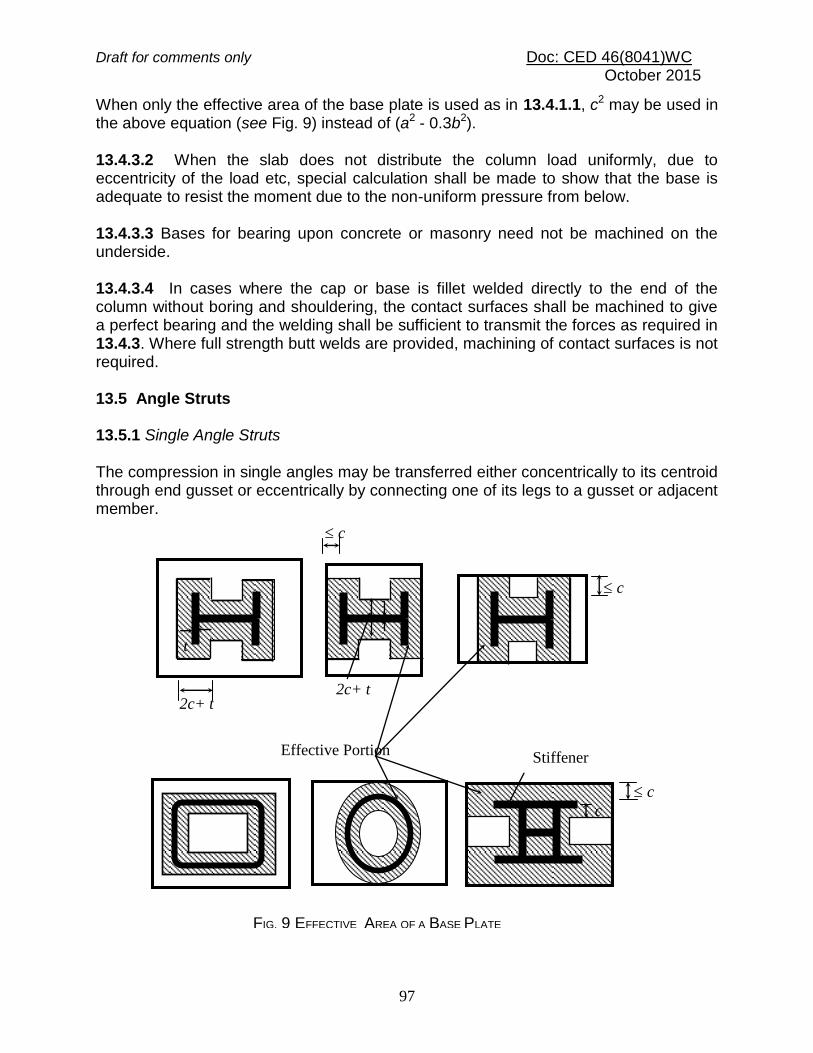
Draft for comments only Doc: CED 46(8041)WC October 2015
97
When only the effective area of the base plate is used as in 13.4.1.1, c2 may be used in the above equation (see Fig. 9) instead of (a2 - 0.3b2). 13.4.3.2 When the slab does not distribute the column load uniformly, due to eccentricity of the load etc, special calculation shall be made to show that the base is adequate to resist the moment due to the non-uniform pressure from below. 13.4.3.3 Bases for bearing upon concrete or masonry need not be machined on the underside. 13.4.3.4 In cases where the cap or base is fillet welded directly to the end of the column without boring and shouldering, the contact surfaces shall be machined to give a perfect bearing and the welding shall be sufficient to transmit the forces as required in 13.4.3. Where full strength butt welds are provided, machining of contact surfaces is not required. 13.5 Angle Struts 13.5.1 Single Angle Struts The compression in single angles may be transferred either concentrically to its centroid through end gusset or eccentrically by connecting one of its legs to a gusset or adjacent member.
2c+ t 2c+ t
Stiffener Effective Portion
FIG. 9 EFFECTIVE AREA OF A BASE PLATE
c
c
c
c
t
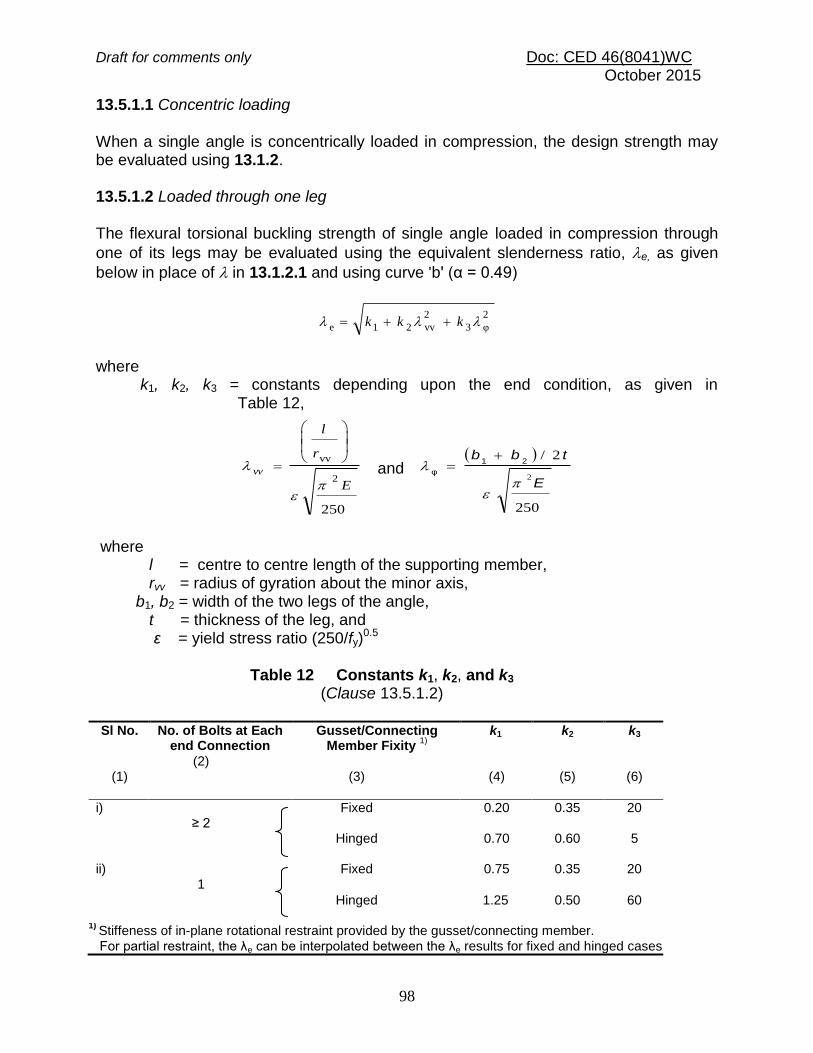
Draft for comments only Doc: CED 46(8041)WC October 2015
98
13.5.1.1 Concentric loading When a single angle is concentrically loaded in compression, the design strength may be evaluated using 13.1.2. 13.5.1.2 Loaded through one leg The flexural torsional buckling strength of single angle loaded in compression through
one of its legs may be evaluated using the equivalent slenderness ratio, e, as given
below in place of in 13.1.2.1 and using curve 'b' (α = 0.49)
2
φ3
2
vv21e kkk
where k1, k2, k3 = constants depending upon the end condition, as given in Table 12,
250
2
vv
E
r
l
vv
and
250
2/
2E
tbb
21
φ
where l = centre to centre length of the supporting member, rvv = radius of gyration about the minor axis, b1, b2 = width of the two legs of the angle, t = thickness of the leg, and ε = yield stress ratio (250/fy)
0.5
Table 12 Constants k1, k2, and k3 (Clause 13.5.1.2)
Sl No.
(1)
No. of Bolts at Each end Connection
(2)
Gusset/Connecting Member Fixity
1)
(3)
k1
(4)
k2
(5)
k3
(6)
i) ≥ 2
Fixed 0.20
0.35 20
Hinged 0.70
0.60 5
ii) 1
Fixed 0.75
0.35 20
Hinged 1.25
0.50 60
1) Stiffeness of in-plane rotational restraint provided by the gusset/connecting member.
For partial restraint, the λe can be interpolated between the λe results for fixed and hinged cases.

Draft for comments only Doc: CED 46(8041)WC October 2015
99
13.5.2 Double Angle Struts 13.5.2.1 For double angle discontinuous struts, connected back to back, on opposite sides of the gusset or a section, by not less than two bolts or rivets in line along the angles at each end, or by the equivalent in welding, the load may be regarded as applied axially. The effective length, KL, in the plane of end gusset shall be taken as between 0.7 and 0.85 times the distance between intersections, depending on the degree of the restraint provided. The effective length, KL, in the plane perpendicular to that of the end gusset, shall be taken as equal to the distance between centers of intersections. The calculated average compressive stress shall not exceed the values based on 13.1.2. The angles shall be connected together over their lengths so as to satisfy the requirements of 13.8 and 16.2.5. 13.5.2.2 Double angle discontinuous struts connected back-to-back, to one side of a gusset or section by one or more bolts or rivets in each angle, or by the equivalent in welding, shall be designed in accordance with 13.5.1 and the angles shall be connected together over their lengths so as to satisfy the requirements of 13.8 and 16.2.5. 13.5.3 Continuous Members Double angle continuous struts such as those forming the flanges, chords or ties of trusses or trussed girders, or the legs of towers shall be designed as axially loaded compression members, and the effective length shall be taken in accordance with 13.2.4. 13.5.4 Combined Stresses In addition to axial loads, if the struts carry loads which cause transverse bending, the combined bending and axial stresses shall be checked in accordance with 14.3. For determining the permissible axial and bending stresses, the effective length shall be taken in accordance with the 13.2 and 14.3. 13.6 Laced Columns 13.6.1 General 13.6.1.1 Members comprising two main components laced and tied, should where practicable, have a radius of gyration about the axis perpendicular to the plane of lacing not less than the radius of gyration about the axis parallel to the plane of lacing [see Figs. 10(a) and 10(b)]. 13.6.1.2 As far as practicable, the lacing system shall be uniform throughout the length of the column.

Draft for comments only Doc: CED 46(8041)WC October 2015
100
13.6.1.3 Except for tie plates as specified in 13.7, double laced systems [see Fig. 10(b)] and single laced systems [see Fig. 10(a)] on opposite sides of the main components shall not be combined with cross members (ties) perpendicular to the longitudinal axis of the strut [see Fig. 10(c)], unless all forces resulting from deformation of the strut members are calculated and provided for in the design of lacing and its fastenings. 13.6.1.4 Single laced systems, on opposite faces of the components being laced together shall preferably be in the same direction so that one is the shadow of the other, instead of being mutually opposed in direction. 13.6.1.5 The effective slenderness ratio, (KL/r)e, of laced columns shall be taken as 1.05 times the (KL/r)0, the actual maximum slenderness ratio, in order to account for shear deformation effects. 13.6.2 Width of Lacing Bars In bolted/riveted construction, the minimum width of lacing bars shall be three times the nominal diameter of the end bolt/rivet. 13.6.3 Thickness of Lacing Bars The thickness of flat lacing bars shall not be less than one-fortieth of its effective length for single lacings and one-sixtieth of the effective length for double lacings. 13.6.3.1 Rolled sections or tubes of equivalent strength may be permitted instead of flats, for lacings. 13.6.4 Angle of Inclination Lacing bars, whether in double or single systems, shall be inclined at an angle not less than 40º nor more than 70º to the axis of the built-up member. 13.6.5 Spacing 13.6.5.1 The maximum spacing of lacing bars, whether connected by bolting, riveting or welding, shall also be such that the maximum slenderness ratio of the components of the main member (a1/r1), between consecutive lacing connections is not greater than 50 or 0.7 times the most unfavourable slenderness ratio of the member as a whole, whichever is less, where a1 is the unsupported length of the individual member between lacing points, and r1 is the minimum radius of gyration of the individual member being laced together. 13.6.5.2 Where lacing bars are not lapped to form the connection to the components of the members, they shall be so connected that there is no appreciable interruption in the triangulation of the system.
Draft for comments only Doc: CED 46(8041)WC October 2015
101
13.6.6 Design of Lacings 13.6.6.1 The lacing shall be proportioned to resist a total transverse shear, Vt, at any point in the member, equal to at least 2.5 percent of the axial force in the member and shall be divided equally among all transverse-lacing systems in parallel planes. 13.6.6.2 For members carrying calculated bending stress due to eccentricity of loading, applied end moments and/or lateral loading, the lacing shall be proportioned to resist the actual shear due to bending, in addition to that specified in 13.6.6.1. 13.6.6.3 The slenderness ratio, KL/r, of the lacing bars shall not exceed 145. In bolted/riveted construction, the effective length of lacing bars for the determination of the design strength shall be taken as the length between the inner end fastener of the bars for single lacing, and as 0.7 of this length for double lacings effectively connected at intersections. In welded construction, the effective lengths shall be taken as 0.7 times the distance between the inner ends of welds connecting the single lacing bars to the members.
NOTE ― The required section for lacing bars as compression/tension members shall be determined by using the appropriate design stresses, fcd subject to the requirements in 13.6.3 to 13.6.6 and Td in 12.1.
13.6.7 Attachment to Main Members The bolting, riveting or welding of lacing bars to the main members shall be sufficient to transmit the force calculated in the bars. Where welded lacing bars overlap the main members, the amount of lap measured along either edge of the lacing bar shall be not less than four times the thickness of the bar or the thickness of the element of the members to which it is connected, whichever is less. The welding should be sufficient to transmit the load in the bar and shall, in any case, be provided along each side of the bar for the full length of lap. 13.6.8 End Tie Plates Laced compression members shall be provided with tie plates as per 13.7 at the ends of lacing systems and at intersection with other members/stays and at points where the lacing systems are interrupted.

Draft for comments only Doc: CED 46(8041)WC October 2015
102
Fig. 10 TOP RESTRAINT CONDITIONS
FIG. 10(a) SINGLE LACED SYSTEM
Lacing on Face B
Lacing on Face A
Preferred Lacing Arrangement
A A
B B
+
Lacing on Face A
Lacing on Face B
Preferred Lacing Arrangement
FIG. 10(b) DOUBLE LACED SYSTEM
FIG. 10(c) DOUBLE LACED AND SINGLE LACED SYSTEM COMBINED WITH CROSS MEMBERS
z z
y
y

Draft for comments only Doc: CED 46(8041)WC October 2015
103
13.7 Battened Columns 13.7.1 General 13.7.1.1 Compression members composed of two main components battened should preferably have the individual members of the same cross section and symmetrically disposed about their major axis. Where practicable, the compression members should have a radius of gyration about the axis perpendicular to the plane of the batten not less than the radius of gyration about the axis parallel to the plane of the batten (see Fig. 11). 13.7.1.2 Battened compression members, not complying with the requirements specified in this section or those subjected to eccentricity of loading, applied moments or lateral forces in the plane of the battens (see Fig. 11), shall be designed according to the exact theory of elastic stability or empirically, based on verification by tests.
NOTE ― If the column section is subjected to eccentricity or other moments about an axis perpendicular to battens, the battens and the column section should be specially designed for such moments and shears.
13.7.1.3 The battens shall be placed opposite to each other at each end of the member and at points where the member is stayed in its length and as far as practicable, be spaced and proportioned uniformly throughout. The number of battens shall be such that the member is divided into not less than three bays within its actual length from centre to centre of end connections.
FIG. 11 BATTEN COLUMN SECTION
z z
C
s
y
y

Draft for comments only Doc: CED 46(8041)WC October 2015
104
13.7.1.4 The effective slenderness ratio (KL/r)e of battened columns, shall be taken as 1.1 times the (KL/r)0, the maximum actual slenderness ratio of the column, to account for shear deformation effects. 13.7.2 Design of Battens 13.7.2.1 Battens Battens shall be designed to carry the bending moments and shear forces arising from transverse shear force Vt equal to 2.5 percent of the total axial force on the whole compression member, at any point in the length of the member, divided equally between parallel planes of battens. Battened member carrying calculated bending moment due to eccentricity of axial loading, calculated end moments or lateral loads parallel to the plane of battens, shall be designed to carry actual shear in addition to the above shear. The main members shall also be checked for the same shear force and bending moments as for the battens. Battens shall be of plates, angles, channels, or I-sections and at their ends shall be riveted, bolted or welded to the main components so as to resist simultaneously a shear Vb = Vt C/NS along the column axis and a moment M = VtC/2N at each connection, where
Vt = transverse shear force as defined above; C = distance between centre-to-centre of battens, longitudinally; N = number of parallel planes of battens; and S = minimum transverse distance between the centroid of the rivet/bolt group/welding connecting the batten to the main member.
13.7.2.2 Tie plates Tie plates are members provided at the ends of battened and laced members, and shall be designed by the same method as battens. In no case shall a tie plate and its fastenings be incapable of carrying the forces for which the lacing or batten has been designed. 13.7.2.3 Size When plates are used for battens, the end battens and those at points where the member is stayed in its length shall have an effective depth, longitudinally, not less than the perpendicular distance between the centroids of the main members. The intermediate battens shall have an effective depth of not less than three quarters of this distance, but in no case shall the effective depth of any batten be less than twice the width of one member, in the plane of the battens. The effective depth of a batten shall be taken as the longitudinal distance between outermost bolts, rivets

Draft for comments only Doc: CED 46(8041)WC October 2015
105
or welds at the ends. The thickness of batten or the tie plates shall be not less than one fiftieth of the distance between the innermost connecting lines of rivets, bolts or welds, perpendicular to the main member. 13.7.2.4 The requirement of bolt size and thickness of batten specified above does not apply when angles, channels or I-sections are used for battens with their legs or flanges perpendicular to the main member. However, it should be ensured that the ends of the compression members are tied to achieve adequate rigidity. 13.7.3 Spacing of Battens 13.7.3.1 In battened compression members where the individual members are not specifically checked for shear stress and bending moments, the spacing of battens, centre-to-centre of its end fastenings, shall be such that the slenderness ratio (KL/r) of any component over that distance shall be not greater than 50 nor greater than 0.7 times the slenderness ratio of the member as a whole about its z-z axis (parallel to the battens). 13.7.4 Attachment to Main Members 13.7.4.1 Welded connections Where tie or batten plates overlap the main members, the amount of lap shall be not less than four times the thickness of the plate. The length of weld connecting each edge of the batten plate to the member shall, in aggregate, be not less than half the depth of the batten plate. At least one-third of the weld shall be placed at each end of this edge. The length of weld and depth of batten plate shall be measured along the longitudinal axis of the main member. In addition, the welding shall be returned along the other two edges of the plates transversely to the axis of the main member for a length not less than the minimum lap specified above. 13.8 Compression Members Composed of Two Components Back-to-Back 13.8.1 Compression members composed of two angles, channels, or tees back-to-back in contact or separated by a small distance, shall be connected together by riveting, bolting or welding so that the ratio of most unfavorable slenderness of each member between the intermediate connections is not greater than 40 or 0.6 times the most unfavorable ratio of slenderness of the strut as a whole, whichever is less [see Section 6(j)]. 13.8.2 In no case shall the ends of the strut be connected together with less than two rivets or bolts or their equivalent in welding, and there shall be not less than two additional connections in between, spaced equidistant along the length of the strut. Where the members are separated back-to-back, the rivets or bolts through

Draft for comments only Doc: CED 46(8041)WC October 2015
106
these connections shall pass through solid washers or packing in between. Where the legs of the connected angles or the connected tees are 125 mm wide or more, or where webs of channels are 150 mm wide or over, not less than two rivets or bolts shall be used in each connection, one on line of each gauge mark. 13.8.3 Where these connections are made by welding, solid packing shall be used to effect the jointing unless the members are sufficiently close together to permit direct welding, and the members shall be connected by welding along both pairs of edges of the main components. 13.8.4 The rivets, bolts or welds in these connections shall be sufficient to carry the shear force and moments, if any, specified for battened struts (see 13.7.3), and in no case shall the rivets or bolts be less than 16 mm diameter for members upto and including 10 mm thick; 20 mm diameter for members upto and including 16 mm thick; and 22 mm diameter for members over 16 mm thick. 13.8.4.1 Compression members connected by such riveting, bolting or welding shall not be subjected to transverse loading in a plane perpendicular to the riveted, bolted or welded surfaces. 13.8.5 Where the components are in contact back-to-back, the spacing of the rivets, bolts or intermittent welds shall not exceed the maximum spacing for compression members as given in Section 6 (j).
SECTION 6(h) DESIGN OF MEMBERS SUBJECTED TO BENDING
14.1 General Members subjected to predominant bending shall have adequate design strength to resist bending moment, shear force, and concentrated forces imposed upon and their combinations. Further, the members shall satisfy the deflection limitation presented in Section 6(e), as serviceability criteria. Member subjected to other forces in addition to bending or biaxial bending shall be designed in accordance with Section 6(i).
14.1.1 Effective Span of Beams The effective span of a beam shall be taken as the distance between the centre of the supports, except where the point of application of the reaction is taken as eccentric at the support, when it shall be permissible to take the effective span as the length between the assumed lines of the reactions.
Draft for comments only Doc: CED 46(8041)WC October 2015
107
14.2 Design Strength in Bending (Flexure) The design bending strength of beam, adequately supported against lateral torsional buckling (laterally supported beam) is governed by the yield stress (see 14.2.1). When a beam is not adequately supported against lateral buckling (laterally un-supported beams) the design bending strength may be governed by lateral torsional buckling strength (see 14.2.2). The factored design moment, M at any section, in a beam due to external actions, shall satisfy
dMM
where
Md = design bending strength of the section, calculated as given in 14.2.1.2. 14.2.1 Laterally Supported Beam A beam may be assumed to be adequately supported at the supports, provided the compression flange has full lateral restraint and nominal torsional restraint at supports supplied by web cleats, partial depth end plates, fin plates or continuity with the adjacent span. Full lateral restraint to compression flange may be assumed to exist if the frictional or other positive restraint of a floor connection to the compression flange of the member is capable of resisting a lateral force not less than 2.5 percent of the maximum force in the compression flange of the member. This may be considered to be uniformly distributed along the flange, provided gravity loads constitute the dominant loading on the member and the floor construction is capable of resisting this lateral force. The design bending strength of a section which are not susceptible to web
buckling under shear before yielding (where d/tw ≤ 67) shall be determined according to 14.2.1.2. 14.2.1.1 Section with webs susceptible to shear buckling before yielding When the flanges are plastic, compact or semi-compact but the web is susceptible to shear buckling before yielding (see 14.4.2.1), the design bending strength shall be calculated using one of the following methods:
a) The bending moment and axial force acting on the section may be assumed to be resisted by flanges only and the web is designed only to resist shear (see 14.4).
b) The bending moment and axial force acting on the section may be assumed to be resisted by the whole section. In such a case, the web shall be designed for combined shear and normal stresses using simple

Draft for comments only Doc: CED 46(8041)WC October 2015
108
elastic theory in case of semi-compact webs and simple plastic theory in the case of compact and plastic webs.
14.2.1.2 When the factored design shear force does not exceed 0.6 Vd, where Vd is the design shear strength of the cross-section (see 14.4), the design bending strength, Md shall be taken as:
Md = b Z p fy / m0
To avoid irreversible deformation under serviceability loads, Md shall be less than 1.2 Ze fy / m0 in case of simply supported and 1.5 Ze fy / m0 in case of cantilever beams; where
b = 1.0 for plastic and compact sections;
b = Ze/ Zp for semi-compact sections; Zp, Ze = plastic and elastic section modulii of the cross-section, respectively fy = yield stress of the material ; and
m0 = partial safety factor (see 11.4.1). 14.2.1.3 When the design shear force (factored), V exceeds 0.6Vd, where Vd is the design shear strength of the cross-section (see 14.4) the design bending strength, Md shall be taken
Md = Mdv
where Mdv = design bending strength under high shear as defined in 15.2.
14.2.1.4 Holes in the tension zone
a) The effect of holes in the tension flange, on the design bending strength need not be considered if
(Anf / Agf) (fy/fu) (m1 / m0 ) / 0.9 where Anf / Agf = ratio of net to gross area of the flange in tension; fy/fu = ratio of yield and ultimate stress of the material; and
m1 /m0 = ratio of partial safety factors against ultimate to yield stress (see 11.4.1).
When the Anf /Agf does not satisfy the above requirement, the reduced effective flange area, Aef satisfying the above equation may be taken as the effective flange area in tension, instead of Agf.
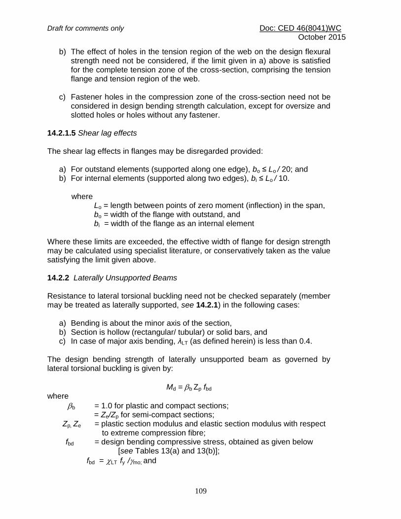
Draft for comments only Doc: CED 46(8041)WC October 2015
109
b) The effect of holes in the tension region of the web on the design flexural strength need not be considered, if the limit given in a) above is satisfied for the complete tension zone of the cross-section, comprising the tension flange and tension region of the web.
c) Fastener holes in the compression zone of the cross-section need not be
considered in design bending strength calculation, except for oversize and slotted holes or holes without any fastener.
14.2.1.5 Shear lag effects The shear lag effects in flanges may be disregarded provided:
a) For outstand elements (supported along one edge), bo ≤ Lo / 20; and b) For internal elements (supported along two edges), bi ≤ Lo / 10.
where Lo = length between points of zero moment (inflection) in the span, bo = width of the flange with outstand, and bi = width of the flange as an internal element
Where these limits are exceeded, the effective width of flange for design strength may be calculated using specialist literature, or conservatively taken as the value satisfying the limit given above. 14.2.2 Laterally Unsupported Beams Resistance to lateral torsional buckling need not be checked separately (member may be treated as laterally supported, see 14.2.1) in the following cases:
a) Bending is about the minor axis of the section, b) Section is hollow (rectangular/ tubular) or solid bars, and c) In case of major axis bending, λLT (as defined herein) is less than 0.4.
The design bending strength of laterally unsupported beam as governed by lateral torsional buckling is given by:
Md = b Zp fbd
where
b = 1.0 for plastic and compact sections; = Ze/Zp for semi-compact sections;
Zp, Ze = plastic section modulus and elastic section modulus with respect to extreme compression fibre;
fbd = design bending compressive stress, obtained as given below [see Tables 13(a) and 13(b)];
fbd = LT fy /mo; and

Draft for comments only Doc: CED 46(8041)WC October 2015
110
LT = bending stress reduction factor to account for lateral torisonal buckling, given by:
0.1
1
5.02
2
LTLTLT
LT
2
LTLTLTLT 2.015.0
LT, the imperfection parameter is given by:
LT = 0.21 for rolled steel section
LT = 0.49 for welded steel section
The non-dimensional slenderness ratio, LT, is given by
crypbLTMfZ / ≤
cryeMfZ /2.1
= bcr,
y
f
f
where Mcr = elastic critical moment calculated in accordance with 14.2.2.1, and fcr ,b = extreme fibre bending compressive stress corresponding to elastic lateral buckling moment (see 14.2.2.1 and Table 14). 14.2.2.1 Elastic lateral torsional buckling moment In case of simply supported, prismatic members with symmetric cross-section, the elastic lateral buckling moment, Mcr, can be determined from:
2
2
2
2
LT
w
t
LT
y
cr
L
EIGI
L
EIM
= b Zp fcr,b
fcr,b of non-slender rolled steel sections in the above equation may be approximately calculated from the values given in the Table 14, which has been prepared using the following equation:
5.02
2
2
/
/
20
11
)/(
1.1
ff
yLT
yLT
bcr,
th
rL
rL
Ef

Draft for comments only Doc: CED 46(8041)WC October 2015
111
Table 13(a) Design Bending Compressive Stress Corresponding to Lateral Buckling, fbd , αLT = 0.21)
(Clause 14.2.2)
fcr,b fy
200 210 220 230 240 250 260 280 300 320 340 360 380 400 420 450 480 510 540
10 000 181.8 190.9 200 209.1 218.2 227.3 236.4 254.5 272.7 290.9 309.1 327.3 345.5 363.6 381.8 409.1 436.4 463.6 490.9
8 000 181.8 190.9 200 209.1 218.2 227.3 236.4 254.5 272.7 290.9 309.1 327.3 345.5 363.6 381.8 409.1 436.4 463.6 490.9
6 000 181.8 190.9 200 209.1 218.2 227.3 236.4 254.5 272.7 290.9 309.1 327.3 345.5 363.6 381.8 409.1 436.4 463.6 490.9
4 000 181.8 190.9 200 209.1 218.2 227.3 236.4 254.5 272.7 290.9 309.1 327.3 345.5 363.6 381.8 409.1 436.4 463.6 490.9
2 000 181.8 190.9 200 209.1 218.2 227.3 236.4 254.5 272.7 290.9 309.1 327.3 345.5 363.6 381.8 409.1 436.4 463.6 490.9
1 000 169.1 179.5 186 196.5 202.9 209.1 219.8 229.1 245.5 261.8 275.1 291.3 300.5 323.6 332.2 355.9 370.9 384.8 412.4
900 169.1 179.5 186 194.5 200.7 204.5 215.1 231.6 242.7 258.9 272 291.3 300.5 316.4 328.4 339.5 366.5 380.2 392.7
800 167.3 177.5 184 190.3 196.4 206.8 212.7 224 240 258.9 268.9 284.7 293.6 301.8 324.5 335.5 349.1 370.9 387.8
700 163.6 171.8 182 188.2 192 202.3 208 226.5 237.3 250.2 259.6 278.2 286.7 294.5 305.5 327.3 340.4 352.4 363.3
600 161.8 168 176 181.9 194.2 197.7 203.3 218.9 226.4 244.4 253.5 261.8 276.4 287.3 294 306.8 322.9 333.8 343.6
500 161.8 166.1 172 179.8 185.5 188.6 200.9 208.7 218.2 232.7 244.2 248.7 259.1 269.1 274.9 286.4 296.7 301.4 314.2
450 158.2 164.2 168 173.5 183.3 186.4 191.5 206.2 215.5 224 231.8 242.2 248.7 258.2 263.5 274.1 279.3 292.1 294.5
400 150.9 162.3 166 169.4 174.5 184.1 186.7 196 204.5 215.3 222.5 229.1 238.4 243.6 248.2 257.7 261.8 264.3 274.9
350 147.3 152.7 162 165.2 170.2 172.7 179.6 188.4 193.6 200.7 210.2 212.7 221.1 225.5 229.1 233.2 240 241.1 245.5
300 143.6 147 152 154.7 161.5 163.6 167.8 175.6 182.7 186.2 194.7 196.4 196.9 203.6 206.2 212.7 213.8 217.9 220.9
250 134.5 137.5 142 144.3 148.4 152.3 153.6 160.4 163.6 165.8 170 173.5 179.6 178.2 179.5 184.1 183.3 185.5 191.5
200 121.8 124.1 126 129.6 130.9 134.1 134.7 137.5 141.8 142.5 145.3 147.3 148.5 149.1 152.7 151.4 152.7 153 157.1
150 101.8 103.1 104 104.5 106.9 106.8 108.7 109.5 111.8 113.5 114.4 114.5 117.5 116.4 118.4 118.6 117.8 120.5 122.7
100 74.5 76.4 76 77.4 76.4 77.3 78 78.9 79.1 78.5 80.4 81.8 79.5 80 80.2 81.8 82.9 83.5 83.5
90 67.3 68.7 70 69 69.8 70.5 70.9 71.3 70.9 72.7 74.2 72 72.5 72.7 72.5 73.6 74.2 74.2 73.6
80 61.8 63 62 62.7 63.3 63.6 63.8 63.6 65.5 64 64.9 65.5 65.6 65.5 64.9 65.5 65.5 64.9 68.7
70 54.5 55.4 56 56.5 56.7 56.8 56.7 56 57.3 58.2 58.7 58.9 58.7 58.2 57.3 57.3 56.7 60.3 58.9
60 47.3 47.7 48 48.1 48 50 49.6 48.4 49.1 49.5 49.5 49.1 48.4 50.9 49.6 49.1 52.4 51 49.1
50 40 40.1 40 41.8 41.5 40.9 40.2 40.7 40.9 40.7 43.3 42.5 41.5 43.6 42 40.9 43.6 41.7 44.2
40 32.7 32.5 32 33.5 32.7 34.1 33.1 33.1 32.7 34.9 34 32.7 34.5 32.7 34.4 32.7 34.9 32.5 34.4
30 25.5 24.8 26 25.1 26.2 25 26 25.5 24.5 26.2 24.7 26.2 24.2 25.5 26.7 24.5 26.2 27.8 24.5
20 16.4 17.2 18 16.7 17.5 18.2 16.5 17.8 16.4 17.5 18.5 16.4 17.3 18.2 19.1 16.4 17.5 18.5 19.6
10 9.1 9.5 8 8.4 8.7 9.1 9.5 7.6 8.2 8.7 9.3 9.8 10.4 7.3 7.6 8.2 8.7 9.3 9.8

Draft for comments only Doc: CED 46(8041)WC October 2015
112
Table 13(b) Design Bending Compressive Stress Corresponding to Lateral Buckling, fbd, αLT = 0.49) (Clause 14.2.2)
fcr,b fy
200 210 220 230 240 250 260 280 300 320 340 360 380 400 420 450 480 510 540
10 000 181.8 190.9 200.0 209.1 218.2 227.3 236.4 254.5 272.7 290.9 309.1 327.3 345.5 363.6 381.8 409.1 436.4 463.6 490.9
8 000 181.8 190.9 200.0 209.1 218.2 227.3 236.4 254.5 272.7 290.9 309.1 327.3 345.5 363.6 381.8 409.1 436.4 463.6 490.9
6 000 181.8 190.9 200.0 209.1 218.2 227.3 236.4 254.5 272.7 290.9 309.1 327.3 345.5 363.6 381.8 409.1 436.4 463.6 490.9
4 000 181.8 190.9 200.0 209.1 218.2 227.3 236.4 254.5 272.7 290.9 309.1 327.3 345.5 363.6 381.8 409.1 436.4 463.6 490.9
2 000 181.8 190.9 200.0 209.1 218.2 227.3 236.4 254.5 272.7 290.9 309.1 327.3 345.5 363.6 381.8 409.1 436.4 463.6 490.9
1 000 160.0 164.2 170.0 179.8 185.5 190.9 196.2 211.3 220.9 235.6 247.3 255.3 266.0 280 290.2 302.7 318.5 329.2 343.6
900 154.5 164.2 170.0 173.5 183.3 188.6 193.8 203.6 218.2 226.9 238.0 252.0 262.5 269.1 282.5 290.5 305.5 319.9 333.8
800 152.7 158.5 168.0 171.5 176.7 181.8 191.5 201.1 210.0 224.0 234.9 242.2 252.2 258.2 271.1 282.3 296.7 306 319.1
700 150.9 154.6 160.0 169.4 172.4 177.3 182.0 196 207.3 215.3 222.5 232.4 238.4 247.3 259.6 270 279.3 292.1 304.4
600 145.5 150.8 154.0 161.0 168.0 172.7 177.3 188.4 193.6 203.6 213.3 222.5 228 236.4 244.4 253.6 261.8 273.5 274.9
500 140.0 145.1 150.0 154.7 159.3 161.4 167.8 175.6 185.5 192 200.9 206.2 214.2 218.2 225.3 229.1 240 245.7 250.4
450 134.5 141.3 144.0 148.5 152.7 156.8 160.7 168 177.3 186.2 191.6 196.4 203.8 210.9 213.8 220.9 231.3 236.5 235.6
400 129.1 135.5 138.0 142.2 148.4 150 153.6 162.9 169.1 174.5 182.4 183.3 193.5 196.4 202.4 208.6 209.5 217.9 220.9
350 123.6 129.8 132.0 135.9 139.6 143.2 148.9 152.7 158.2 162.9 170 173.5 176.2 181.8 183.3 192.3 196.4 199.4 206.2
300 118.2 122.2 126.0 129.6 130.9 134.1 137.1 142.5 147.3 154.2 157.6 157.1 162.4 167.3 168 175.9 178.9 180.8 181.6
250 109.1 112.6 116.0 117.1 120.0 122.7 125.3 129.8 130.9 136.7 139.1 140.7 145.1 149.1 148.9 151.4 152.7 157.6 157.1
200 98.2 101.2 102.0 104.5 104.7 109.1 108.7 112 117.3 119.3 120.5 121.1 124.4 127.3 126 130.9 130.9 129.8 132.5
150 83.6 84.0 86.0 87.8 89.5 88.6 89.8 91.6 95.5 96.0 95.8 98.2 100.2 101.8 103.1 102.3 104.7 106.6 103.1
100 63.6 63.0 64.0 64.8 65.5 65.9 66.2 68.7 68.2 69.8 71.1 68.7 69.1 72.7 72.5 73.6 74.2 74.2 73.6
90 58.2 57.3 60.0 58.5 61.1 61.4 61.5 61.1 62.7 64.0 64.9 65.5 65.6 65.5 64.9 65.5 65.5 64.9 68.7
80 52.7 53.5 54.0 54.4 54.5 54.5 54.4 56 57.3 58.2 58.7 58.9 58.7 58.2 61.1 61.4 61.1 60.3 58.9
70 47.3 47.7 48.0 48.1 48.0 50.0 49.6 50.9 49.1 49.5 52.5 52.4 51.8 50.9 53.5 53.2 52.4 55.6 54.0
60 41.8 42.0 42.0 41.8 43.6 43.2 42.5 43.3 43.6 43.6 43.3 45.8 44.9 47.3 45.8 45.0 48.0 46.4 49.1
50 36.4 36.3 36.0 35.5 37.1 36.4 37.8 38.2 38.2 37.8 37.1 39.3 38.0 40.0 38.2 40.9 39.3 37.1 39.3
40 29.1 30.5 30.0 29.3 30.5 29.5 30.7 30.5 30.0 32.0 30.9 32.7 31.1 32.7 30.5 32.7 30.5 32.5 34.4
30 23.6 22.9 22.0 23.0 24.0 22.7 23.6 22.9 24.5 23.3 24.7 22.9 24.2 25.5 22.9 24.5 26.2 23.2 24.5
20 16.4 15.3 16.0 16.7 15.3 15.9 16.5 15.3 16.4 17.5 15.5 16.4 17.3 18.2 15.3 16.4 17.5 18.5 14.7
10 9.1 7.6 8.0 8.4 8.7 9.1 9.5 7.6 8.2 8.7 9.3 9.8 6.9 7.3 7.6 8.2 8.7 9.3 9.8
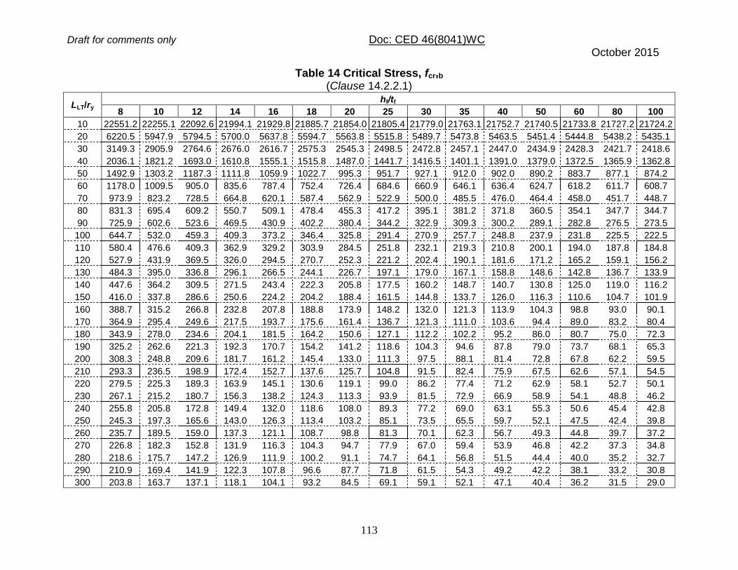
Draft for comments only Doc: CED 46(8041)WC October 2015
113
Table 14 Critical Stress, fcr,b (Clause 14.2.2.1)
LLT/ry hf/tf
8 10 12 14 16 18 20 25 30 35 40 50 60 80 100
10 22551.2 22255.1 22092.6 21994.1 21929.8 21885.7 21854.0 21805.4 21779.0 21763.1 21752.7 21740.5 21733.8 21727.2 21724.2
20 6220.5 5947.9 5794.5 5700.0 5637.8 5594.7 5563.8 5515.8 5489.7 5473.8 5463.5 5451.4 5444.8 5438.2 5435.1
30 3149.3 2905.9 2764.6 2676.0 2616.7 2575.3 2545.3 2498.5 2472.8 2457.1 2447.0 2434.9 2428.3 2421.7 2418.6
40 2036.1 1821.2 1693.0 1610.8 1555.1 1515.8 1487.0 1441.7 1416.5 1401.1 1391.0 1379.0 1372.5 1365.9 1362.8
50 1492.9 1303.2 1187.3 1111.8 1059.9 1022.7 995.3 951.7 927.1 912.0 902.0 890.2 883.7 877.1 874.2
60 1178.0 1009.5 905.0 835.6 787.4 752.4 726.4 684.6 660.9 646.1 636.4 624.7 618.2 611.7 608.7
70 973.9 823.2 728.5 664.8 620.1 587.4 562.9 522.9 500.0 485.5 476.0 464.4 458.0 451.7 448.7
80 831.3 695.4 609.2 550.7 509.1 478.4 455.3 417.2 395.1 381.2 371.8 360.5 354.1 347.7 344.7
90 725.9 602.6 523.6 469.5 430.9 402.2 380.4 344.2 322.9 309.3 300.2 289.1 282.8 276.5 273.5
100 644.7 532.0 459.3 409.3 373.2 346.4 325.8 291.4 270.9 257.7 248.8 237.9 231.8 225.5 222.5
110 580.4 476.6 409.3 362.9 329.2 303.9 284.5 251.8 232.1 219.3 210.8 200.1 194.0 187.8 184.8
120 527.9 431.9 369.5 326.0 294.5 270.7 252.3 221.2 202.4 190.1 181.6 171.2 165.2 159.1 156.2
130 484.3 395.0 336.8 296.1 266.5 244.1 226.7 197.1 179.0 167.1 158.8 148.6 142.8 136.7 133.9
140 447.6 364.2 309.5 271.5 243.4 222.3 205.8 177.5 160.2 148.7 140.7 130.8 125.0 119.0 116.2
150 416.0 337.8 286.6 250.6 224.2 204.2 188.4 161.5 144.8 133.7 126.0 116.3 110.6 104.7 101.9
160 388.7 315.2 266.8 232.8 207.8 188.8 173.9 148.2 132.0 121.3 113.9 104.3 98.8 93.0 90.1
170 364.9 295.4 249.6 217.5 193.7 175.6 161.4 136.7 121.3 111.0 103.6 94.4 89.0 83.2 80.4
180 343.9 278.0 234.6 204.1 181.5 164.2 150.6 127.1 112.2 102.2 95.2 86.0 80.7 75.0 72.3
190 325.2 262.6 221.3 192.3 170.7 154.2 141.2 118.6 104.3 94.6 87.8 79.0 73.7 68.1 65.3
200 308.3 248.8 209.6 181.7 161.2 145.4 133.0 111.3 97.5 88.1 81.4 72.8 67.8 62.2 59.5
210 293.3 236.5 198.9 172.4 152.7 137.6 125.7 104.8 91.5 82.4 75.9 67.5 62.6 57.1 54.5
220 279.5 225.3 189.3 163.9 145.1 130.6 119.1 99.0 86.2 77.4 71.2 62.9 58.1 52.7 50.1
230 267.1 215.2 180.7 156.3 138.2 124.3 113.3 93.9 81.5 72.9 66.9 58.9 54.1 48.8 46.2
240 255.8 205.8 172.8 149.4 132.0 118.6 108.0 89.3 77.2 69.0 63.1 55.3 50.6 45.4 42.8
250 245.3 197.3 165.6 143.0 126.3 113.4 103.2 85.1 73.5 65.5 59.7 52.1 47.5 42.4 39.8
260 235.7 189.5 159.0 137.3 121.1 108.7 98.8 81.3 70.1 62.3 56.7 49.3 44.8 39.7 37.2
270 226.8 182.3 152.8 131.9 116.3 104.3 94.7 77.9 67.0 59.4 53.9 46.8 42.2 37.3 34.8
280 218.6 175.7 147.2 126.9 111.9 100.2 91.1 74.7 64.1 56.8 51.5 44.4 40.0 35.2 32.7
290 210.9 169.4 141.9 122.3 107.8 96.6 87.7 71.8 61.5 54.3 49.2 42.2 38.1 33.2 30.8
300 203.8 163.7 137.1 118.1 104.1 93.2 84.5 69.1 59.1 52.1 47.1 40.4 36.2 31.5 29.0

The following simplified equation may be used in the case of prismatic members made of standard rolled I-sections and welded doubly symmetric I-sections, for calculating the elastic lateral buckling moment, Mcr (see Table 14).
5.022
/
/
20
11
2
ff
yLT
2
LT
fy
cr
th
rL
L
hEIM
where
It = torsional constant 3/3
iitb for open section;
Iw = warping constant; Iy,,ry = moment of inertia and radius of gyration, respectively about the weaker axis; LLT = effective length for lateral torsional buckling (see 14.3);
hf = center to center distance between flanges; and tf = thickness of the flange.
Mcr for different beam sections, considering loading, support condition, and non-symmetric section, shall be more accurately calculated using the method given in Annex D. The above equations for calculating Mcr may be conservatively used for channel sections.
14.3 Effective Length for Lateral Torsional Buckling
14.3.1 For simply supported beams and girders of span length, L, where no lateral restraint to the compression flanges is provided, but where each end of the beam is restrained against torsion, the effective length LLT of the lateral buckling to be used in 14.2.2.1 shall be taken as in Table 15.
In simply supported beams with intermediate lateral restraints against lateral torsional buckling, the effective length for lateral torsional buckling, LLT to be used in 14.2.2.1, shall be taken as the length of the relevant segment in between the lateral restraints. In the case of intermediate partial lateral restraints, the effective length, LLT shall be taken as equal to 1.2 times the length of the relevant segment in between the partial lateral restraints. Restraint against torsional rotation at supports in these beams may be provided by:
a) web or flange cleats, or b) bearing stiffeners acting in conjunction with the bearing of the beam, or c) lateral end frames or external supports providing lateral restraint to the
compression flanges at the ends, or d) their being built into walls.

Draft for comments only Doc: CED 46(8041)WC October 2015
115
Table 15 Effective Length for Simply Supported Beams, LLT
(Clause 14.3.1)
Sl No.
Conditions of Restraint at Supports
Loading Condition
Torsional restraint Warping Restraint
Normal
Destabilizing
(1) (2)
(3) (4) (5)
i) Fully restrained Both flanges fully restrained
0.70 L 0.85 L
ii) Fully restrained Only compression flange fully restrained
0.75 L 0.90 L
iii) Fully restrained Both flanges partially restrained
0.80 L 0.95 L
iv) Fully restrained Only compression flange partially restrained
0.85 L 1.00 L
v) Fully restrained No restraint in both flanges
1.00 L 1.20 L
vi) Partially restrained by bottom flange support connection
No restraint in both flanges
1.0 L+ 2D 1.2 L+2D
vii) Partially restrained by bottom flange bearing support
No restraint in both flanges
1.2 L+2D 1.4 L+2D
NOTES 1 Torsional restraint prevents rotation about the longitudinal axis.
2 Warping restraint prevents rotation of the flange in its plane. 3 D is the overall depth of the beam
14.3.2 For beams, which are provided with members giving effective lateral restraint to the compression flange at intervals along the span, in addition to the end torsional restraint required in 14.3.1, the effective length for lateral torsional buckling shall be taken as the distance, centre-to-centre of the restraint members in the relevant segment under normal loading condition and 1.2 times this distance, where the load is not acting on the beam at or above the shear centre and towards the shear centre, so as to have destabilizing effect during lateral torsional buckling deformation. 14.3.3 For cantilever beams of projecting length L, the effective length LLT to be used in 14.2.2.1 shall be taken as in Table16 for different support conditions.
Draft for comments only Doc: CED 46(8041)WC October 2015
116
14.3.4 Where a member is provided intermediate lateral supports to improve the lateral buckling strength, these restraints should have sufficient strength and stiffness to prevent lateral movement of the compression flange at that point, relative to the end supports. The intermediate lateral restraints should be either connected to an appropriate bracing system capable of transferring the restraint force to the effective lateral support at the ends of the member, or should be connected to an independent robust part of the structure capable of transferring the restraint force. Two or more parallel member requiring such lateral restraint shall not be simply connected together assuming mutual dependence for the lateral restraint. The intermediate lateral restraints should be connected to the member as close to the compression flange as practicable. Such restraints should be closer to the shear centre of the compression flange than to the shear centre of the section. However, if torsional restraint preventing relative rotation between the two flanges is provided, the intermediate lateral restraint may be connected at any appropriate level. For beams which are provided with members giving effective lateral restraint at intervals along the span, the effective lateral restraint shall be capable of resisting a force of 2.5 percent of the maximum force in the compression flange taken as divided equally between the points at which the restraint members are provided. Further, each restraint point should be capable of resisting 1 percent of the maximum force in the compression flange. 14.3.4.1 In a series of such beams, with solid webs, which are connected together by the same system of restraint members, the sum of the restraining forces required shall be taken as 2.5 percent of the maximum flange force in one beam only. 14.3.4.2 In the case of a series of latticed beams, girders or roof trusses which are connected together by the same system of restraint members, the sum of the restraining forces required shall be taken as 2.5 percent of the maximum force in the compression flange plus 1.25 percent of this force for every member of the series other than the first, up to a maximum total of 7.5 percent. 14.3.5 Purlins adequately restrained by sheeting need not be normally checked for the restraining forces required by rafters, roof trusses or portal frames that carry predominately roof loads provided there is bracing of adequate stiffness in the plane of rafters or roof sheeting which is capable of acting as a stressed skin diaphragm. 14.3.6 In case of beams with double curvature bending, adequate direct lateral support to the compression flange in the hogging moment region may be provided as given above for simply supported beam. The effect of support to the tension (top) flange in the hogging moment region on lateral restraint to the compression flange may be considered as per specialist literature.

Draft for comments only Doc: CED 46(8041)WC October 2015
117
14.4 Shear
The factored design shear force, V, in a beam due to external actions shall satisfy
V Vd
where
Vd = design strength
= Vn / m0
where
m0 = partial safety factor against shear failure (see 11.4.1).
The nominal shear strength of a cross-section, Vn, may be governed by plastic shear resistance (see 14.4.1) or strength of the web as governed by shear buckling (see 14.4.2).
14.4.1 The nominal plastic shear resistance under pure shear is given by:
Vn = Vp
where
3
ywv
p
fAV
Av = shear area; and fyw = yield strength of the web. 14.4.1.1 The shear area may be calculated as given below: a) I-and channel sections: Major Axis Bending: Hot-Rolled – h tw Welded – d tw Minor Axis Bending: Hot-Rolled or welded – 2b tf b) Rectangular hollow sections of uniform thickness: Loaded parallel to depth (h) – A h / (b + h) Loaded parallel to width (b) – A b / (b + h) c) Circular hollow tubes of uniform thickness – 2 A / π d) Plates and solid bars – A where A = cross-section area, b = overall breadth of tubular section, breadth of I- section flanges, d = clear depth of the web between flanges,
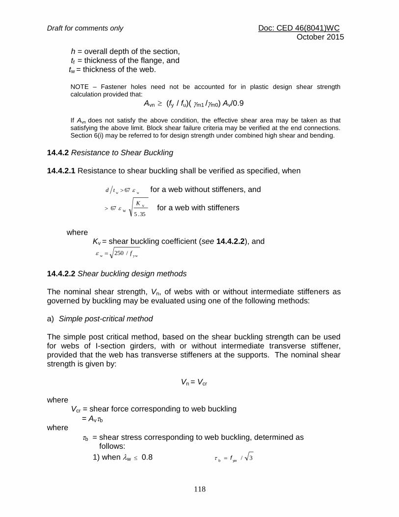
Draft for comments only Doc: CED 46(8041)WC October 2015
118
h = overall depth of the section, tf = thickness of the flange, and tw = thickness of the web.
NOTE – Fastener holes need not be accounted for in plastic design shear strength calculation provided that:
Avn (fy / fu)( m1 /m0) Av/0.9
If Avn does not satisfy the above condition, the effective shear area may be taken as that satisfying the above limit. Block shear failure criteria may be verified at the end connections. Section 6(i) may be referred to for design strength under combined high shear and bending.
14.4.2 Resistance to Shear Buckling 14.4.2.1 Resistance to shear buckling shall be verified as specified, when
ww
67 td for a web without stiffeners, and
35.5
67v
w
K for a web with stiffeners
where Kv = shear buckling coefficient (see 14.4.2.2), and
yww
/250 f
14.4.2.2 Shear buckling design methods The nominal shear strength, Vn, of webs with or without intermediate stiffeners as governed by buckling may be evaluated using one of the following methods: a) Simple post-critical method The simple post critical method, based on the shear buckling strength can be used for webs of I-section girders, with or without intermediate transverse stiffener, provided that the web has transverse stiffeners at the supports. The nominal shear strength is given by:
Vn = Vcr
where Vcr = shear force corresponding to web buckling
= Avb
where
b = shear stress corresponding to web buckling, determined as follows:
1) when w 0.8 3/ywb
f

Draft for comments only Doc: CED 46(8041)WC October 2015
119
2) when 0.8 < w < 1.2 3/8.08.01ywwb
f
3) when w 1.2 b = fyw/ 2
3w
where λw = Non -dimensional web slenderness ratio for shear buckling stress, given by:
)3(ecr,yww
f
cr,e = the elastic critical shear stress of the web =
22
2
/112w
v
td
EK
where
= Poisson’s ratio, and Kv = 5.35 when transverse stiffeners are provided only at supports = 4.0 + 5.35 /(c/d)2 for c/d < 1.0
= 5.35 + 4.0 /(c/d)2 for c/d 1.0 where c, d are the spacing of transverse stiffeners and depth of the web, respectively.
b) Tension field method The tension field method, based on the post-shear buckling strength, may be used for webs with intermediate transverse stiffeners, in addition to the transverse stiffeners at supports, provided the panels adjacent to the panel under tension field action, or the end posts provide anchorage for the tension
fields and if c/d 1.0, where c, d are the spacing of transverse stiffeners and depth of the web, respectively. In the tension field method, the nominal shear resistance, Vn, is given by:
Vn=Vtf
where
sin9.0vwtfbvtf
ftwAV Vp
where
b = shear stress corresponding to buckling of web 14.4.2.2(a);
fv = yield strength of the tension field obtained from 5.0
22
b
2
yw 3f ;
=1.5 b sin 2;
= inclination of the tension field nearly5.1
tan1
c
d
;
wtf = the width of the tension field, given by:
= d cos - (c - sc - st) sin ;

Draft for comments only Doc: CED 46(8041)WC October 2015
120
fyw = yield stress of the web; d = depth of the web; c = spacing of transverse stiffeners in the web; and
sc, st = anchorage lengths of tension field along the compression and tension flange respectively, obtained from:
ctf
Ms
w
5.0
sin
2
yw
fr
where Mfr = reduced plastic moment capacity of the respective flange plate (disregarding any edge stiffener) after accounting for the axial force, Nf in the flange, due to overall bending and any external axial force in the cross-section, and is calculated as :
2
0yffffyf
2
fffr //125.0 mftbNftbM
where bf , tf = width and thickness of the relevant flange respectively; and fyf = Yield stress of the flange.

Draft for comments only Doc: CED 46(8041)WC October 2015
121
Table 16 Effective Length, LLT for Cantilever of Length, L (Clause 14.3.3)
____________________________________________________________________________
Restraint Condition
Loading Conditions
At Support At top Normal Destabilizing
(2) (3) (4) (5)
a) Continuous, with lateral restraint to top flange
�
i) Free ii) Lateral restraint to top flange iii)Torsional restraint iv)Lateral and torsional restraint
3.0L 2.7L 2.4L 2.1L
7.5L 7.5L 4.5L 3.6L
b) Continuous, with partial torsional restraint
i) Free ii) Lateral restraint to top flange iii) Torsional restraint iv)Lateral and torsional restraint
2.0L 1.8L 1.6L 1.4L
5.0L 5.0L 3.0L 2.4L
c) Continuous, with lateral and torsional restraint
�
i) Free ii) Lateral restraint to top flange iii) Torsional restraint iv) Lateral and torsional restraint
1.0L 0.9L 0.8L 0.7L
2.5L 2.5L 1.5L 1.2L
d) Restrained laterally, torsionally and against rotation on plan
i) Free ii) Lateral restraint to top flange iii) Torsional restraint iv)Lateral and torsional restraint
0.8L 0.7L 0.6L 0.5L
1.4L 1.4L 0.6L 0.5L
Top restraint conditions
i) Free
ii)Lateral restraint to top flange
iii) Torsional restraint
iv) Lateral and torsional restraint

Draft for comments only Doc: CED 46(8041)WC October 2015
122
14.5 Stiffened Web Panels 14.5.1 End Panels Design (see Fig.12) The girders in which the interior panel (panel A) is designed using tension field action, the end panels shall be designed using only simple post critical method, according to 14.4.2.2(a). Additionally, the end panel along with the stiffeners should be checked as a beam spanning between the flanges to resist a shear force, Rtf, and a moment, Mtf, due to tension field forces as given in 14.5.3. Further, end stiffener should be capable of resisting the reaction plus a compressive force due to the moment, equal to Mtf. [see Fig. (12)]. 14.5.2 End Panels Designed Using Tension Field Action (see Figs. 13 and 14) The end panel (Panel A) shall be designed according to 14.4.2.2(b). Additionally it should be provided with an end post consisting of a single or double stiffener, (see Figs. 13 and 14), satisfying the following.
a) Single Stiffener (see Fig. 13) The top of the end post should be rigidly connected to the flange using full strength welds.
The end post should be capable of resisting the reaction plus a moment from
the anchor forces equal to 2/3 Mtf due to tension field forces, where Mtf is obtained from 14.5.3. The width and thickness of the end post are not to exceed the width and thickness of the flange.
b) Double Stiffener (see Fig. 14) The end post should be checked as a beam spanning between the flanges of the girder and capable of resisting a shear force Rtf and a moment, Mtf due to the tension field forces as given in 14.5.3.
14.5.3 Anchor Forces The resultant longitudinal shear, Rtf, and a moment Mtf from the anchor of tension field forces are evaluated as given below:
2
q
tf
HR and
10
dHM
q
tf
where

Draft for comments only Doc: CED 46(8041)WC October 2015
123
2/1
125.1
p
cr
pq
V
VVH
3
y
p
dtfV
d = web depth, If the actual factored shear force, V in the panel designed using tension field approach is less than the shear strength, Vtf as given in 14.4.2.2(b), then the values
of Hq may be reduced by the ratio crtf
cr
VV
VV
where Vtf = the basic shear strength for the panel utilizing tension field action as given in 14.4.2.2(b), and Vcr = critical shear strength for the panel designed utilizing tension field action as given in 14.4.2.2(a).
NOTES 1 Panel A is designed utilizing tension field action as given in 14.4.2.2(b). 2 Panel B is designed using simple post critical method as given in 14.4.2.2(a). 3 Bearing stiffener is designed for the compressive force due to bearing plus compressive force due to the moment Mtf as given in 14.5.3.
FIG. 12 END PANEL DESIGNED NOT USING TENSION FIELD ACTION
Bearing
stiffener
Panel B Panel A
c
d
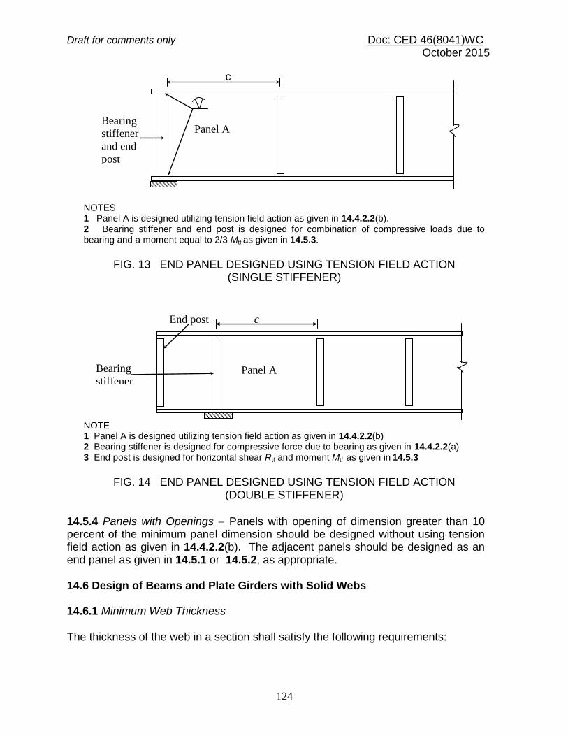
Draft for comments only Doc: CED 46(8041)WC October 2015
124
NOTES 1 Panel A is designed utilizing tension field action as given in 14.4.2.2(b). 2 Bearing stiffener and end post is designed for combination of compressive loads due to bearing and a moment equal to 2/3 Mtf as given in 14.5.3.
FIG. 13 END PANEL DESIGNED USING TENSION FIELD ACTION (SINGLE STIFFENER)
NOTE 1 Panel A is designed utilizing tension field action as given in 14.4.2.2(b) 2 Bearing stiffener is designed for compressive force due to bearing as given in 14.4.2.2(a) 3 End post is designed for horizontal shear Rtf and moment Mtf as given in 14.5.3
FIG. 14 END PANEL DESIGNED USING TENSION FIELD ACTION
(DOUBLE STIFFENER)
14.5.4 Panels with Openings Panels with opening of dimension greater than 10 percent of the minimum panel dimension should be designed without using tension field action as given in 14.4.2.2(b). The adjacent panels should be designed as an end panel as given in 14.5.1 or 14.5.2, as appropriate. 14.6 Design of Beams and Plate Girders with Solid Webs 14.6.1 Minimum Web Thickness The thickness of the web in a section shall satisfy the following requirements:
c
Panel A Bearing
stiffener
and end
post
End post
Panel A Bearing
stiffener
c
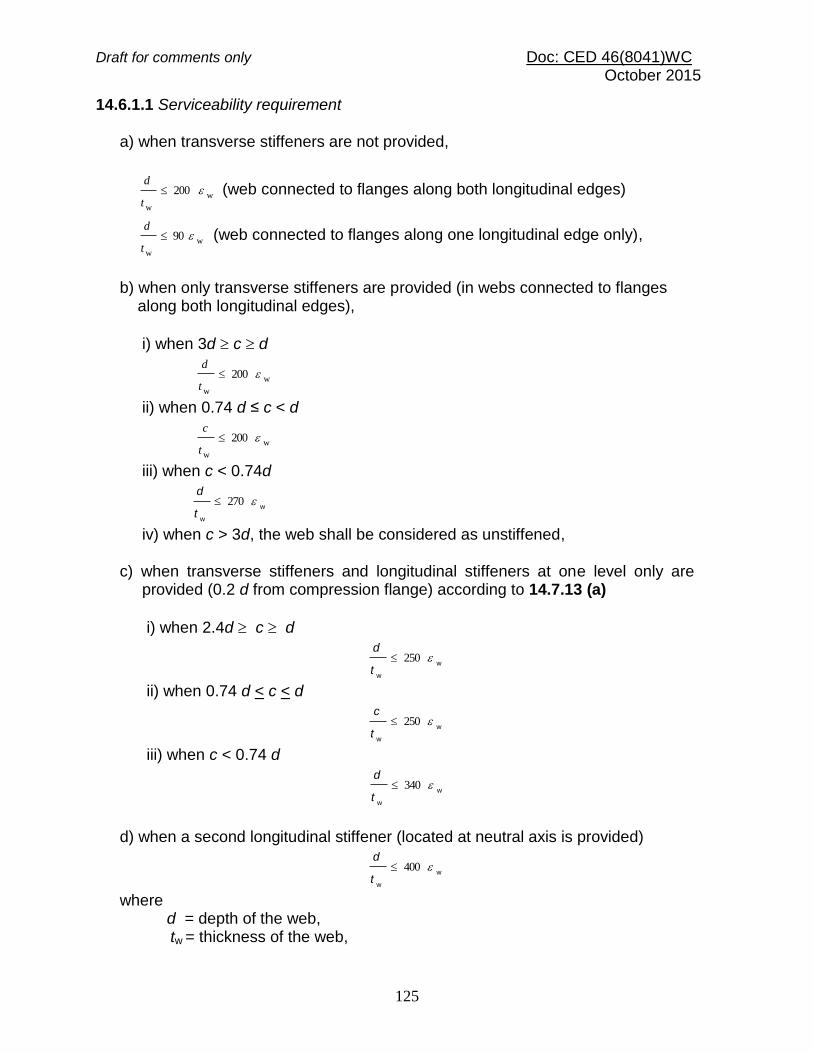
Draft for comments only Doc: CED 46(8041)WC October 2015
125
14.6.1.1 Serviceability requirement a) when transverse stiffeners are not provided,
w
w
200 t
d (web connected to flanges along both longitudinal edges)
w
w
90 t
d (web connected to flanges along one longitudinal edge only),
b) when only transverse stiffeners are provided (in webs connected to flanges along both longitudinal edges),
i) when 3d c d
w
w
200 t
d
ii) when 0.74 d ≤ c < d
w
w
200 t
c
iii) when c < 0.74d
w
w
270t
d
iv) when c > 3d, the web shall be considered as unstiffened, c) when transverse stiffeners and longitudinal stiffeners at one level only are provided (0.2 d from compression flange) according to 14.7.13 (a)
i) when 2.4d c d
w
w
250t
d
ii) when 0.74 d < c < d
w
w
250t
c
iii) when c < 0.74 d
w
w
340t
d
d) when a second longitudinal stiffener (located at neutral axis is provided)
w
w
400t
d
where d = depth of the web,
tw = thickness of the web,

Draft for comments only Doc: CED 46(8041)WC October 2015
126
c = spacing of transverse stiffener (see Fig. 12 and Fig. 13),
w
= yield stress ratio of web = yw
f250 , and
fyw = yield stress of the web. 14.6.1.2 Compression flange buckling requirement In order to avoid buckling of the compression flange into the web, the web thickness shall satisfy the following: a) When transverse stiffeners are not provided
2345
f
w
t
d
b) When transverse stiffeners are provided and
i) when c 1.5 d
2
f
w
345t
d
ii) when c < 1.5d
f
w
345t
d
where d = depth of the web, tw = thickness of the web, c = spacing of transverse stiffener (see Fig. 12 and Fig. 13),
f
= yield stress ratio of flange = yf
f250 , and
fyf = yield stress of compression flange. 14.6.2 Sectional Properties 14.6.2.1 The effective sectional area of compression flanges shall be the gross area with deductions for excessive width of plates as specified for compression members [see Section 6(g)] and for open holes occurring in a plane perpendicular to the direction of stress at the section being considered (see 14.2.1.4). The effective sectional area of tension flanges shall be the gross sectional area with deductions for holes as specified in 14.2.1.4.
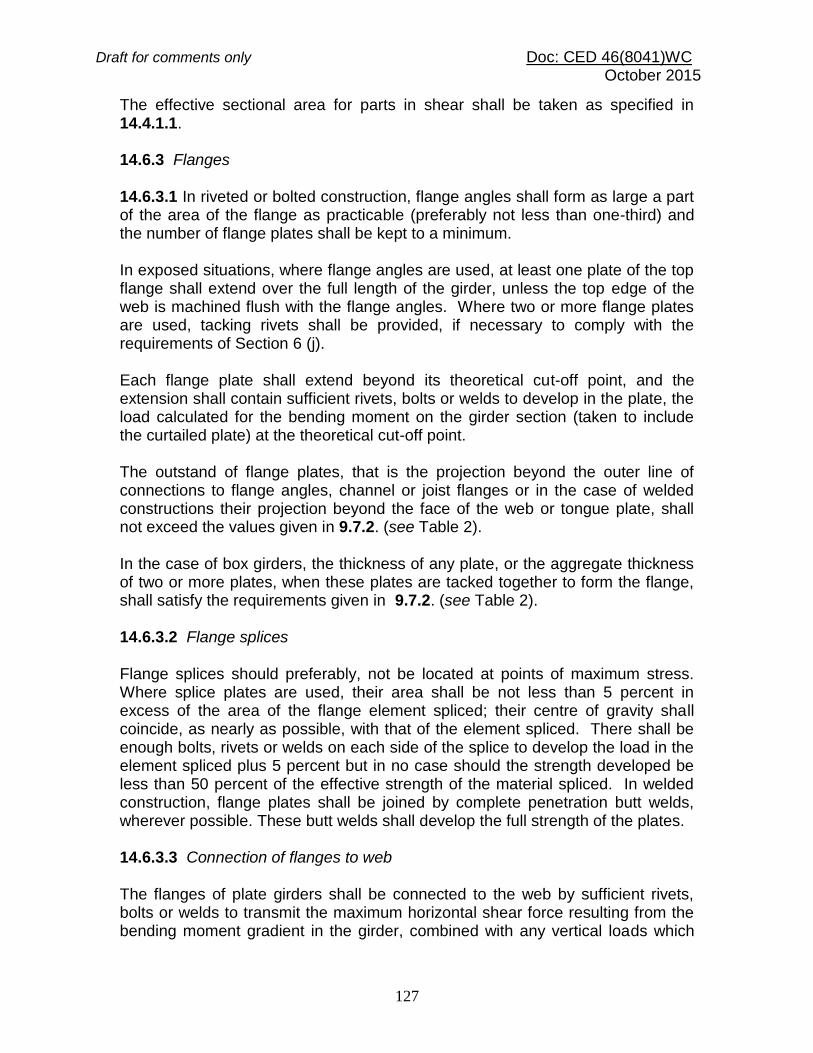
Draft for comments only Doc: CED 46(8041)WC October 2015
127
The effective sectional area for parts in shear shall be taken as specified in 14.4.1.1. 14.6.3 Flanges 14.6.3.1 In riveted or bolted construction, flange angles shall form as large a part of the area of the flange as practicable (preferably not less than one-third) and the number of flange plates shall be kept to a minimum. In exposed situations, where flange angles are used, at least one plate of the top flange shall extend over the full length of the girder, unless the top edge of the web is machined flush with the flange angles. Where two or more flange plates are used, tacking rivets shall be provided, if necessary to comply with the requirements of Section 6 (j). Each flange plate shall extend beyond its theoretical cut-off point, and the extension shall contain sufficient rivets, bolts or welds to develop in the plate, the load calculated for the bending moment on the girder section (taken to include the curtailed plate) at the theoretical cut-off point. The outstand of flange plates, that is the projection beyond the outer line of connections to flange angles, channel or joist flanges or in the case of welded constructions their projection beyond the face of the web or tongue plate, shall not exceed the values given in 9.7.2. (see Table 2). In the case of box girders, the thickness of any plate, or the aggregate thickness of two or more plates, when these plates are tacked together to form the flange, shall satisfy the requirements given in 9.7.2. (see Table 2). 14.6.3.2 Flange splices Flange splices should preferably, not be located at points of maximum stress. Where splice plates are used, their area shall be not less than 5 percent in excess of the area of the flange element spliced; their centre of gravity shall coincide, as nearly as possible, with that of the element spliced. There shall be enough bolts, rivets or welds on each side of the splice to develop the load in the element spliced plus 5 percent but in no case should the strength developed be less than 50 percent of the effective strength of the material spliced. In welded construction, flange plates shall be joined by complete penetration butt welds, wherever possible. These butt welds shall develop the full strength of the plates. 14.6.3.3 Connection of flanges to web The flanges of plate girders shall be connected to the web by sufficient rivets, bolts or welds to transmit the maximum horizontal shear force resulting from the bending moment gradient in the girder, combined with any vertical loads which

Draft for comments only Doc: CED 46(8041)WC October 2015
128
are directly applied to the flange. If the web is designed using tension field method as given in 14.4.2.2 b), the weld should be able to transfer the tension field stress, fyw acting on the web. 14.6.3.4 Bolted/riveted construction For girders in exposed situations and which do not have flange plates for their entire length, the top edge of the web plate shall be flush with or above the angles, and the bottom edge of the web plate shall be flush with or set back from the angles. 14.6.3.5 Welded construction The gap between the web plates and flange plates shall be kept to a minimum and for fillet welds shall not exceed 1 mm at any point before welding. 14.6.4 Webs 14.6.4.1 Effective sectional area of web of plate girder The effective cross-sectional area shall be taken as the full depth of the web plate multiplied by the thickness.
NOTE ― Where webs are varied in thickness in the depth of the section by the use of tongue plates or the like, or where the proportion of the web included in the flange area is 25 percent or more of the overall depth, the above approximation is not permissible and the maximum shear stress shall be computed on theory.
14.6.4.2 Splices in webs Splices and cutouts for service ducts in the webs should preferably not be located at points of maximum shear force and heavy concentrated loads. Splices in the webs of the plate girders and rolled sections shall be designed to resist the shears and moments at the spliced section (see Annex E). In riveted or bolted construction, splice plates shall be provided on each side of the web. In welded construction, web splices shall preferably be made with complete penetration butt welds. 14.6.4.3 Where additional plates are required to augment the strength of the web, they shall be placed on each side of the web and shall be equal in thickness. The proportion of shear force assumed to be resisted by these plates shall be limited by the amount of horizontal shear which they can transmit to the flanges through their fastenings, and such reinforcing plates and their fastenings shall be carried up to the points at which the flange without the additional plates is adequate.
Draft for comments only Doc: CED 46(8041)WC October 2015
129
14.7 Stiffener Design 14.7.1 General 14.7.1.1 When the web of a member acting alone (that is, without stiffeners) proves inadequate, stiffeners for meeting the following requirements should be provided:
a) Intermediate transverse web stiffener ― To improve the buckling strength of a slender web due to shear (see 14.7.2).
b) Load carrying stiffener ― To prevent local buckling of the web due to
concentrated loading (see 14.7.3 and 14.7.5). c) Bearing stiffener ― To prevent local crushing of the web due to
concentrated loading (see 14.7.4 and 14.7.6). d) Torsion stiffener ― To provide torsional restraint to beams and girders at
supports (see 14.7.9). e) Diagonal stiffener ― To provide local reinforcement to a web under shear
and bearing (see 14.7.7). f) Tension stiffener ― To transmit tensile forces applied to a web through a
flange (see 14.7.8).
The same stiffeners may perform more than one function and their design should comply with the requirements of all the functions for which designed. 14.7.1.2 Outstand of web stiffeners Unless the outer edge is continuously stiffened, the outstand from the face of the
web should not exceed 20tq .
When the outstand of web stiffener is between 14tq and 20tq, then the stiffener design should be on the basis of a core section with an outstand of only
14tq , where tq is the thickness of the stiffener. 14.7.1.3 Stiff bearing length The stiff bearing length of any element, b1, is that length which cannot deform appreciably in bending. To determine b1, the dispersion of load through a steel bearing element should be taken as 45o through solid material, such as bearing plates, flange plates, etc. (see Fig.15).

Draft for comments only Doc: CED 46(8041)WC October 2015
130
14.7.1.4 Eccentricity Where a load or reaction is applied eccentric to the centerline of the web or where the centroid of the stiffener does not lie on the centerline of the web, the resulting eccentricity of loading should be accounted for in the design of the stiffener. 14.7.1.5 Buckling resistance of stiffeners The buckling resistance Fqd should be based on the design compressive stress fcd (see 13.1.2.1) of a strut (curve c), the radius of gyration being taken about the axis parallel to the web. The effective section is the full area or core area of the stiffener (see 14.7.1.2) together with an effective length of web on each side of the centerline of the stiffeners, limited to 20 times the web thickness. The design strength used should be the minimum value obtained for buckling about the web or the stiffener. The effective length for intermediate transverse stiffeners used in calculating the buckling resistance, Fqd, should be taken as 0.7 times the length, L of the stiffener. The effective length for load carrying web stiffeners used in calculating the buckling resistance, Fxd, assumes that the flange through which the load or reaction is applied is effectively restrained against lateral movement relative to the other flange, the effective length should be taken as:
a) LKL 7.0 , when flange is restrained against rotation in the plane of
the stiffener (by other structural elements)
b) LKL , when flange is not so restrained:
where L = length of the stiffener.
If the load or reaction is applied to the flange by a compression member, then unless effective lateral restraint is provided at that point, the stiffener should be designed as part of the compression member applying the load, and the connection between the column and beam flange shall be checked for the effects of the strut action.

Draft for comments only Doc: CED 46(8041)WC October 2015
131
14.7.2 Design of Intermediate Transverse Web Stiffeners 14.7.2.1 General Intermediate transverse stiffeners may be provided on one or both sides of the web. 14.7.2.2 Spacing Spacing of intermediate stiffeners, where provided, shall comply with 14.6.1 depending on the thickness of the web. 14.7.2.3 Outstand of stiffeners The outstand of the stiffeners should comply with 14.7.1.2. 14.7.2.4 Minimum stiffeners Transverse web stiffeners not subject to external loads or moments should have a second moment of area, Is about the centerline of the web, if stiffeners are on both sides of the web and about the face of the web , if single stiffener on only one side of the web is used such that:
if 2d
c , 3
wtdI
s75.0 , and
if 2d
c , 2
35.1
c
tdI
3
w
s
where d = depth of the web;
FIG. 15 STIFF BEARING LENGTH, b1
45º 45
º
b1 b1
b1
45º

Draft for comments only Doc: CED 46(8041)WC October 2015
132
tw = minimum required web thickness for spacing using tension field action, as given in 14.4.2.1; and c = actual stiffener spacing. 14.7.2.5 Buckling check on intermediate transverse web stiffeners ― Stiffeners not subjected to external loads or moments should be checked for a stiffener force:
qdm0crqFVVF /
where Fqd = Design resistance of the intermediate stiffeners; V = Factored shear force adjacent to the stiffener; and Vcr = Shear buckling resistance of the web panel designed without using tension field action as given in 14.4.2.2 a). Stiffeners subject to external loads and moments should meet the conditions for load carrying web stiffeners in 14.7.3. In addition they should satisfy the following interaction expression:
1
yq
q
xd
x
qd
xq
M
M
F
F
F
FF
If Fq < Fx , then (Fq – Fx) should be taken as zero; where Fq = stiffener force given above; Fqd =design resistance of an intermediate web stiffener corresponding to buckling about an axis parallel to the web (see 14.7.1.5); Fx = external load or reaction at the stiffener; Fxd = design resistance of a load carrying stiffener corresponding to buckling about axis parallel to the web (see 14.7.1.5); Mq = moment on the stiffener due to eccentrically applied load and transverse load, if any; and Myq = yield moment capacity of the stiffener based on its elastic modulus about its centroidal axis parallel to the web. 14.7.2.6 Connection of intermediate stiffeners to web Intermediate transverse stiffeners not subject to external loading should be connected to the web so as to withstand a shear between each component of the stiffener and the web (in kN/mm) of not less than:
s
2
w 5/ bt
Draft for comments only Doc: CED 46(8041)WC October 2015
133
where tw = web thickness, in mm; and bs = outstand width of the stiffener, in mm. For stiffeners subject to external loading, the shear between the web and the stiffener due to such loading has to be added to the above value. Stiffeners not subject to external loads or moments may terminate clear of the tension flange and in such a situation the distance cut short from the line of the weld should not be more than 4tw. 14.7.3 Load Carrying Stiffeners 14.7.3.1 Web check Load carrying web stiffeners should be provided where compressive forces applied through a flange by loads or reactions exceed the buckling strength, Fcdw, of the unstiffened web, calculated using the following: The effective length of the web for evaluating the slenderness ratio is calculated as in 14.7.1.5. The area of cross-section is taken as (b1+n1) tw.
where b1 = width of stiff bearing on the flange(see 14.7.1.3), and
n1 = dispersion of the load through the web at 45, to the level of half the depth of the cross-section. The buckling strength of this web about axis parallel to the web is calculated as given in 13.1.2.1, using curve ‘c’. 14.7.4 Bearing Stiffeners Bearing stiffeners should be provided for webs where forces applied through a flange by loads or reactions exceeding the local capacity of the web at its connection to the flange, Fw, given by:
m0ywww
/21
ftnbF
where b1 = stiff bearing length (see 14.7.1.3), n2 = length obtained by dispersion through the flange to the web junction at a slope of 1:2.5 to the plane of the flange, tw = thickness of the web, and fyw = yield stress of the web.

Draft for comments only Doc: CED 46(8041)WC October 2015
134
14.7.5 Design of Load Carrying Stiffeners 14.7.5.1 Buckling check The external load or reaction, Fx on a stiffener should not exceed the buckling resistance, Fxd of the stiffener as given in 14.7.1.5.
Where the stiffener also acts as an intermediate stiffener it should be checked for the effect of combined loads in accordance with 14.7.2.5. 14.7.5.2 Bearing check ― Load carrying web stiffeners should also be of sufficient size that the bearing strength of the stiffener, Fpsd, given below is not less than the load transferred, Fx
)8.0/(m0yqqpsd
fAF ≥ Fx
where Fx = external load or reaction, Aq = area of the stiffener in contact with the flange, and fyq = yield stress of the stiffener. 14.7.6 Design of Bearing Stiffeners Bearing stiffeners should be designed for the applied load or reaction less the local capacity of the web as given in 14.7.4. Where the web and the stiffener material are of different strengths the lesser value should be assumed to calculate the capacity of the web and the stiffener. Bearing stiffeners should project nearly as much as the overhang of the flange through which load is transferred. 14.7.7 Design of Diagonal Stiffeners Diagonal stiffeners should be designed to carry the portion of the applied shear and bearing that exceeds the capacity of the web. Where the web and the stiffener are of different strengths, the value for design should be taken as given in 14.7.6. 14.7.8 Design of Tension Stiffeners Tension stiffeners should be designed to carry the portion of the applied load or reaction less the capacity of the web as given in 14.7.4 for bearing stiffeners. Where the web and the stiffener are of different strengths, the value for design should be taken as given in 14.7.6.

Draft for comments only Doc: CED 46(8041)WC October 2015
135
14.7.9 Torsional Stiffeners Where bearing stiffeners are required to provide torsional restraint at the supports of the beam, they should meet the following criteria: a) Conditions of 14.7.4, and b) Second moment of area of the stiffener section about the centerline of the web, Is should be such that:
cfss
TDI3
34.0
where
006.0s
for LLT /ry < 50;
= 0.3/( LLT /ry ) for 50 < LLT /ry ≤ 100; = 30/( LLT /ry )
2 for LLT /ry > 100; D = Overall depth of beam at support, Tcf = Maximum thickness of compression flange in the span under consideration, KL = Laterally unsupported effective length of the compression flange of the beam, and ry = Radius of gyration of the beam about the minor axis. 14.7.10 Connection to Web of Load Carrying and Bearing Stiffeners ― Stiffeners, which resist loads or reactions applied through a flange, should be connected to the web by sufficient welds or fasteners to transmit a design force equal to the lesser of:
a) Tension capacity of the stiffener; and b) Sum of the forces applied at the two ends of the stiffener when they act
in the same direction or the larger of the forces when they act in opposite directions.
Stiffeners, which do not extend right across the web, should be of such length that the shear stress in the web due to the design force transmitted by the stiffener does not exceed the shear strength of the web. In addition, the capacity of the web beyond the end of the stiffener should be sufficient to resist the applied force. 14.7.11 Connection to Flanges 14.7.11.1 In tension Stiffeners required to resist tension should be connected to the flange transmitting the load by continuous welds or non-slip fasteners.

Draft for comments only Doc: CED 46(8041)WC October 2015
136
14.7.11.2 In compression Stiffeners required to resist compression should either be fitted against the loaded flange or connected by continuous welds or non-slip fasteners. The stiffener should be fitted against or connected to both flanges when:
a) a load is applied directly over a support; or b) it forms the end stiffener of a stiffened web; or c) it acts as a torsion stiffener.
14.7.12 Hollow Sections Where concentrated loads are applied to hollow sections consideration should be given to local stresses and deformations and the section reinforced as necessary. 14.7.13 Horizontal Stiffeners Where horizontal stiffeners are used in addition to vertical stiffeners, they shall be as follows:
a) One horizontal stiffener shall be placed on the web at a distance from the compression flange equal to 1/5 of the distance from the compression flange angle, plate or tongue plate to the neutral axis when the thickness of the web is less than the limits specified in 14.6.1. The stiffener shall be designed so that Is is not less than 4ctw
3 where Is and tw are as defined in 14.7.2.4 and c is the actual distance between the vertical stiffeners;
b) A second horizontal stiffener (single or double) shall be placed at the neutral axis of the girder when the thickness of the web is less than the limit specified in 14.6.1. This stiffener shall be designed so that Is is not less than d2 tw
3 where Is and tw are as defined in 14.7.2.4 and d2 is twice the clear distance from the compression flange angles, plates or tongue plates to the neutral axis;
c) Horizontal web stiffeners shall extend between vertical stiffeners, but need not be continuous over them; and
d) Horizontal stiffeners may be in pairs arranged on each side of the web, or single located on one side of the web.
14.8 Box Girders The design and detailing of box girders shall be such as to give full advantage of its higher load carrying capacity. Box girder shall be designed in accordance with specialist literature. The diaphragms and horizontal stiffeners should conform to 14.7.12 and 14.7.13.

Draft for comments only Doc: CED 46(8041)WC October 2015
137
14.8.1 All diaphragms shall be connected such as to transfer the resultant shears to the web and flanges. 14.8.2 Where the concentrated or moving load does not act directly on top of the web, the local effect shall be considered in the design of flanges and the diaphragms. 14.9 Purlins and Sheeting Rails (Girts) 14.9.1 All purlins shall be designed in accordance with the requirements for beams as specified in 14.2.1 and 14.2.2. The limitations of bending stress based on lateral instability of the compression flange shall be considered if the purlin does not receive adequate support from bracings and sheathings in the plane of compression flange. In any case the maximum bending moment shall not exceed the values specified in 14.2.1. The calculated deflections should not exceed those permitted for the type of roof cladding used, as specified in 11.6.1. In calculating the bending moment, advantage may be taken of the continuity of the purlin over supports. The bending about the two axes shall be determined separately and checked according to the biaxial bending requirements specified in Section 6(i). 14.10 Bending in a Non-Principal Plane 14.10.1 When the flexural deflection of a member is constrained to a non-principal plane by lateral restraints preventing lateral deflection, then the force exerted by the restraints shall be determined, and the principal axes bending moments acting on the member shall be calculated from these forces and applied forces, by a rational analysis. The combined effect of bending about the principal axes shall satisfy the requirements of Section 6(i). 14.10.2 When the deflections of a member loaded in a non-principal plane are unconstrained; the principal axes bending moments shall be calculated by a rational analysis. The combined effect of bending about the principal axes shall satisfy the requirements of Section 6(i).

Draft for comments only Doc: CED 46(8041)WC October 2015
138
SECTION 6(i) MEMBER SUBJECTED TO COMBINED FORCES 15 MEMBER SUBJECTED TO COMBINED FORCES 15.1 General This section governs the design of members subjected to combined forces, such as shear force and bending, axial force and bending, or shear force, axial force and bending. 15.2 Combined Shear and Bending 15.2.1 No reduction in moment capacity of the section is necessary as long as the cross section is not subjected to high shear force (factored value of applied shear force is less than or equal to 60 percent of the shear strength of the section as given in 14.4). The moment capacity may be taken as, Md (see 14.2) without any reduction. 15.2.2 When the factored value of the applied shear force is high (exceeds the limit specified in 15.2.1), the factored moment of the section should be less than the moment capacity of the section under higher shear force, Mdv, calculated as given below:
a) Plastic or Compact Section
m0yfddddv
fZMMMMe
2.1
where
2
1/2 d
VV ,
Md = plastic design moment of the whole section disregarding high shear force effect (see 14.2.1.2) considering web buckling effects (see 14.2.1.1), V = factored applied shear force as governed by web yielding or web buckling, Vd = design shear strength as governed by web yielding or web buckling (see 14.4.1 or 8.4.2), Mfd = plastic design strength of the area of the cross section
excluding the shear area, considering partial safety factor m0, and Ze = elastic section modulus of the whole section.
b) Semi-compact Section
m0edv/
yfZM
Draft for comments only Doc: CED 46(8041)WC October 2015
139
15.3 Combined Axial Force and Bending Moment Under combined axial force and bending moment, section strength as governed by material failure and member strength as governed by buckling failure shall be checked in accordance with 15.3.1 and 15.3.2 respectively. 15.3.1 Section Strength 15.3.1.1 Plastic and compact sections In the design of members subjected to combined axial force (tension or compression) and bending moment, the following should be satisfied
0.1
21
ndz
z
ndy
y
M
M
M
M
Conservatively, the following equation may also be used under combined axial force and bending moment
0.1
dz
z
dy
y
dM
M
M
M
N
N
where My, Mz = factored applied moments about the minor and major axis of the cross-section, respectively; Mndy, Mndz= design reduced flexural strength under combined axial force and the respective uniaxial moment acting alone (see 15.3.1.2); N = factored applied axial force (Tension, T or Compression, P); Nd = design strength in tension, Td as obtained from 12 or in
compression due to yielding given by m0ygd /γfAN ;
Mdy, Mdz = design strength under corresponding moment acting alone (see 14.2); Ag = gross area of the cross section; 1, 2 = constants as given in Table 17; and
m0γ = partial factor of safety in yielding.
15.3.1.2 For plastic and compact sections without bolts holes, the following approximations may be used for evaluating Mndy and Mndz: a) Plates
Mnd = Md (1 – n2)

Draft for comments only Doc: CED 46(8041)WC October 2015
140
b) Welded I or H-sections
ydyndyM
a
anMM
d
2
11
where n ≥ a
Mndz = Mdz (1 - n) / (1 - 0.5a) Mdz where
n = N / Nd and a = (A - 2 b tf ) / A 0.5
c) For standard I or H sections
Mndz = 1.11 Mdz (1 - n) Mdz
for n ≤ 0.2, Mndy = Mdy
for n > 0.2, Mndy = 1.56 Mdy (1 - n) (n + 0.6)
Mndz = 1.11 Mdz (1 - n) Mdz
d) For rectangular hollow sections and welded box sections When the section is symmetric about both axes and without bolt holes
Mndy = Mdy (1 - n) / (1 - 0.5af) Mdy
Mndz = Mdz (1 - n) / (1 - 0.5aw) Mdz
where
aw = (A - 2 b tf ) / A 0.5
af = (A-2 h tw) / A 0.5 e) Circular hollow tubes without bolt holes
Mnd = 1.04 Md (1 - n1.7) Md
Table 17 Constants 1 and 2
(Clause 15.3.1.1)
Sl No. (1)
Section
(2)
1
(3)
2
(4)
i) I and Channel 5n 1
2
ii) Circular tubes 2
2
iii) Rectangular tubes 1.66/(1- 1.13n2)≤ 6 1.66/(1- 1.13n2) ≤ 6

Draft for comments only Doc: CED 46(8041)WC October 2015
141
iv) Solid rectangles
1.73+1.8n3 1.73+1.8 n3
NOTE ― n = N/Nd
15.3.1.3 Semi-compact section In the absence of high shear force (see 15.2.1), semi-compact section design is satisfactory under combined axial force and bending, if the maximum longitudinal stress under combined axial force and bending, fx satisfies the following criteria:
fx fy /m0
For cross section without holes, the above criteria reduces to,
0.1
dz
z
dy
y
dM
M
M
M
N
N
where Nd, Mdy, Mdz are as defined in 15.3.1.1. 15.3.2 Overall Member Strength Members subjected to combined axial force and bending moment shall be checked for overall buckling failure as given in this section. 15.3.2.1 Bending and axial tension The reduced effective moment, Meff, under tension and bending calculated as given below, should not exceed the bending strength due to lateral torsional buckling, Md (see 14.2.2),
AZTMM /ceeff
Md
where M, T = factored applied moment and tension, respectively; A = area of cross-section; Zec = elastic section modulus of the section with respect to extreme compression fibre; and
= 0.8, if T and M can vary independently, or otherwise = 1.0.

Draft for comments only Doc: CED 46(8041)WC October 2015
142
15.3.2.2 Bending and axial compression Members subjected to combined axial compression and biaxial bending shall satisfy the following interaction relationships:
0.16.0
0.1
dz
zmz
z
dy
y
dz
dz
z
LT
dy
ymy
y
dy
M
MCK
M
MCK
P
P
M
MK
M
MCK
P
P
ymy
where Cmy, Cmz = equivalent uniform moment factor as per Table 18; P = applied axial compression under factored load; My, Mz = maximum factored applied bending moments about y and z-axis of the member, respectively; Pdy, Pdz = design strength under axial compression as governed by buckling about minor (y) and major (z) axis respectively; Mdy, Mdz = design bending strength about y (minor) or z (major) axis considering laterally unsupported length of the cross-section [see Section 6(h)]; Ky = 1+ (λy - 0.2)ny ≤ 1 + 0.8 ny; Kz = 1 + (λz - 0.2)nz ≤ 1+ 0.8 nz, and
KLT = 25.0
1.01
25.0
1.01
mLT
y
mLT
yLT
C
n
C
n
where ny, nz = ratio of actual applied axial force to the design axial strength for buckling about the y and z-axis, respectively, and CmLT = Equivalent uniform moment factor for lateral torsional buckling as per Table 18 corresponding to the actual moment gradient between lateral supports against torsional deformation in the critical region under consideration.

Draft for comments only Doc: CED 46(8041)WC October 2015
143
Table 18 Equivalent Uniform Moment Factor (Clause 9.3.2.2)
Bending Moment Diagram Range
Cmy, Cmz, CmLT
Uniform Loading
Concentrated Load
(1) (2) (3) (4)
−1 ≤ ψ ≤ 1
0.6 + 0.4 ψ ≥ 0.4
0 ≤ αs≤ 1
−1 ≤ ψ ≤ 1
0.2 + 0.8 αs ≥ 0.4
0.2 + 0.8 αs ≥ 0.4
−1 ≤ αs ≤ 0
0 ≤ ψ ≤ 1
0.1 − 0.8 αs ≥ 0.4
− 0.8 αs ≥ 0.4
−1 ≤ ψ ≤ 0
0.1(1−ψ) −0.8 αs ≥ 0.4
0.2(1−ψ) −0.8 αs ≥ 0.4
0 ≤ αh ≤ 1
−1 ≤ ψ ≤ 1
0.95 − 0.05 αh
0.90 + 0.10 αh
−1 ≤ αh ≤ 0
0 ≤ ψ ≤ 1
0.95 + 0.05 αh
0.90 + 0.10 αh
−1 ≤ ψ ≤ 0
0.95 + 0.05 αh (1+2 ψ)
0.90 + 0.1αh (1+2 ψ)
For members with sway buckling mode, the equivalent uniform moment factor Cmy = Cmz = 0.9.
Cmy, Cmz, CmLT shall be obtained according to the bending moment diagram between the relevant braced points Moment factor Bending axis Points braced in direction Cmy z-z y-y Cmz y-y z-z CmLT z-z z-z
SECTION 6 (j) CONNECTIONS 16 CONNECTIONS 16.1 General 16.1.1 This section deals with the design and detailing requirements for joints between members. Connection elements consist of components such as cleats, gusset plates, brackets, connecting plates and connectors such as rivets, bolts, pins, and welds. The connections in a structure shall be designed so as to be consistent with the assumptions made in the analysis of the structure and comply with the requirements
M M
Mh Ms
Mh
αs = Ms/ Mh
Mh
Mh
Ms
αh = Mh/ Ms
My for Cmy
Mz
for Cmz
for CmLT

Draft for comments only Doc: CED 46(8041)WC October 2015
144
specified in this section. Connections shall be capable of transmitting the calculated design actions. 16.1.2 Where members are connected to the surface of a web or the flange of a section, the ability of the web or the flange to transfer the applied forces locally should be checked and where necessary, local stiffening provided. 16.1.3 Ease of fabrication and erection should be considered in the design of connections. Attention should be paid to clearances necessary for field erection, tolerances, tightening of fasteners, welding procedures, subsequent inspection, surface treatment and maintenance. 16.1.4 The ductility of steel assists the distribution of forces generated within a joint. Effects of residual stresses and stresses due to tightening of fasteners and normal tolerances of fit-up need not therefore be considered in connection design, provided ductile behaviour is ensured. 16.1.5 In general, use of different forms of fasteners to transfer the same force shall be avoided. However, when different forms of fasteners are used to carry a shear load or when welding and fasteners are combined, then one form of fastener shall be normally designed to carry the total load. Nevertheless, fully tensioned friction grip bolts may be designed to share the load with welding, provided the bolts are fully tightened to develop necessary pretension after welding. 16.1.6 The partial safety factor in the evaluation of design strength of connections shall be taken as given in Table 5. 16.2 Location Details of Fasteners 16.2.1 Clearances for Holes for Fasteners Bolts may be located in standard size, over size, short slotted or long slotted hole.
a) Standard clearance hole ― Except where fitted bolts, bolts in low-clearance or oversize holes are specified, the diameter of standard clearance holes for fasteners shall be as given in Table 19.
b) Over size hole ― Holes of size larger than the standard clearance holes, as
given in Table 19 may be used in slip resistant connections and hold down bolted connections, only where specified, provided the over size holes in the outer ply is covered by a cover plate of sufficiently large size and thickness and having a hole not larger than the standard clearance hole (and hardened washer in slip resistant connections).
c) Short and long slots ― Slotted holes of size larger than the standard clearance
hole, as given in Table 19 may be used in slip resistant connections and hold
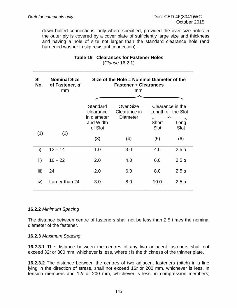
Draft for comments only Doc: CED 46(8041)WC October 2015
145
down bolted connections, only where specified, provided the over size holes in the outer ply is covered by a cover plate of sufficiently large size and thickness and having a hole of size not larger than the standard clearance hole (and hardened washer in slip resistant connection).
Table 19 Clearances for Fastener Holes
(Clause 16.2.1)
Sl No.
(1)
Nominal Size of Fastener, d
mm
(2)
Size of the Hole = Nominal Diameter of the
Fastener + Clearances mm
Standard clearance
in diameter and Width
of Slot
(3)
Over Size Clearance in
Diameter
(4)
Clearance in the Length of the Slot
Short Slot
(5)
Long Slot
(6)
i) 12 – 14
1.0 3.0 4.0 2.5 d
ii) 16 – 22
2.0 4.0 6.0 2.5 d
iii) 24
2.0 6.0 8.0 2.5 d
iv) Larger than 24
3.0 8.0 10.0 2.5 d
16.2.2 Minimum Spacing The distance between centre of fasteners shall not be less than 2.5 times the nominal diameter of the fastener. 16.2.3 Maximum Spacing 16.2.3.1 The distance between the centres of any two adjacent fasteners shall not exceed 32t or 300 mm, whichever is less, where t is the thickness of the thinner plate. 16.2.3.2 The distance between the centres of two adjacent fasteners (pitch) in a line lying in the direction of stress, shall not exceed 16t or 200 mm, whichever is less, in tension members and 12t or 200 mm, whichever is less, in compression members;
Draft for comments only Doc: CED 46(8041)WC October 2015
146
where t is the thickness of the thinner plate. In the case of compression members wherein forces are transferred through butting faces, this distance shall not exceed 4.5 times the diameter of the fasteners for a distance equal to 1.5 times the width of the member from the butting faces. 16.2.3.3 The distance between the centres of any two consecutive fasteners in a line adjacent and parallel to an edge of an outside plate shall not exceed 100 mm plus 4t or 200 mm, whichever is less, in compression and tension members; where t is the thickness of the thinner outside plate. 16.2.3.4 When fasteners are staggered at equal intervals and the gauge does not exceed 75 mm, the spacing specified in 16.2.3.2 and 16.2.3.3 between centres of fasteners may be increased by 50 percent, subject to the maximum spacing specified in 16.2.3.1. 16.2.4 Edge and End Distances 16.2.4.1 The edge distance is the distance at right angles to the direction of stress from the centre of a hole to the adjacent edge. The end distance is the distance in the direction of stress from the centre of a hole to the end of the element. In slotted holes, the edge and end distances should be measured from the edge or end of the material to the centre of its end radius or the centre line of the slot, whichever is smaller. In oversize holes, the edge and end distances should be taken as the distance from the relevant edge/end plus half the diameter of the standard clearance hole corresponding to the fastener, less the nominal diameter of the oversize hole. 16.2.4.2 The minimum edge and end distances from the centre of any hole to the nearest edge of a plate shall not be less than 1.7 times the hole diameter in case of sheared or hand-flame cut edges; and 1.5 times the hole diameter in case of rolled, machine-flame cut, sawn and planed edges.
16.2.4.3 The maximum edge distance to the nearest line of fasteners from an edge of
any un-stiffened part should not exceed 12 t, where = (250/fy)1/2 and t is the thickness
of the thinner outer plate. This would not apply to fasteners interconnecting the components of back to back tension members. Where the members are exposed to corrosive influences, the maximum edge distance shall not exceed 40 mm plus 4t, where t is the thickness of thinner connected plate. 16.2.5 Tacking Fasteners 16.2.5.1 In case of members covered under 16.2.4.3, when the maximum distance between centres of two adjacent fasteners as specified in 16.2.4.3 is exceeded, tacking fasteners not subjected to calculated stress shall be used.

Draft for comments only Doc: CED 46(8041)WC October 2015
147
16.2.5.2 Tacking fasteners shall have spacing in a line not exceeding 32 times the thickness of the thinner outside plate or 300 mm, whichever is less. Where the plates are exposed to the weather, the spacing in line shall not exceed 16 times the thickness of the thinner outside plate or 200 mm, whichever is less. In both cases, the distance between the lines of fasteners shall not be greater than the respective pitches. 16.2.5.3 All the requirements specified in 16.2.5.2 shall generally apply to compression members, subject to the stipulations in Section 6(g) affecting the design and construction of compression members. 16.2.5.4 In tension members [see Section 6(f)] composed of two flats, angles, channels or tees in contact back to back or separated back to back by a distance not exceeding the aggregate thickness of the connected parts, tacking fasteners with solid distance pieces shall be provided at a spacing in line not exceeding 1 000 mm. 16.2.5.5 For compression members covered in Section 6(g), tacking fasteners in a line shall be spaced at a distance not exceeding 600 mm. 16.2.6 Countersunk Heads For countersunk heads, one-half of the depth of the countersinking shall be neglected in calculating the length of the fastener in bearing in accordance with 16.3.3. For fasteners in tension having countersunk heads, the tensile strength shall be reduced by 33.3 percent. No reduction is required to be made in shear strength calculations. 16.3 Bearing Type Bolts 16.3.1 Effective Areas of Bolts 16.3.1.1 Since threads can occur in the shear plane, the area Ae for resisting shear should normally be taken as the net tensile stress area, An of the bolts. For bolts where the net tensile stress area is not defined, An shall be taken as the area at the root of the threads. 16.3.1.2 Where it can be shown that the threads do not occur in the shear plane, Ae
may be taken as the cross section area, As at the shank. 16.3.1.3 In the calculation of thread length, allowance should be made for tolerance and thread run off. 16.3.2 A bolt subjected to a factored shear force (Vsb) shall satisfy the condition
Vsb ≤ Vdb where Vdb is the design strength of the bolt, taken as the smaller of the value as governed by shear, Vdsb (see 16.3.3) and bearing, Vdpb (see 16.3.4).

Draft for comments only Doc: CED 46(8041)WC October 2015
148
16.3.3 Shear Capacity of Bolt The design strength of the bolt, Vdsb as governed by shear strength is given by:
Vdsb = Vnsb / mb where Vnsb = nominal shear capacity of a bolt, calculated as follows:
sbsnbn
u
nsbAnAn
fV
3
where fu = ultimate tensile strength of a bolt; nn = number of shear planes with threads intercepting the shear plane; ns = number of shear planes without threads intercepting the shear plane; Asb = Nominal plain shank area of the bolt; and Anb = Net shear area of the bolt at threads, may be taken as the area corresponding to root diameter at the thread.
16.3.3.1 Long joints When the length of the joint, lj of a splice or end connection in a compression or tension element containing more than two bolts (i.e. the distance between the first and last rows of bolts in the joint, measured in the direction of the load transfer) exceeds 15d in the direction of load, the nominal shear capacity (see 16.3.2), Vdb shall be reduced by the
factor Ij, given by:
lj = 1.075 – lj / (200 d) but 0.75 ≤ lj ≤ 1.0 = 1.075 – 0.005(lj /d) where d = Nominal diameter of the fastener.
NOTE ― This provision does not apply when the distribution of shear over the length of joint is uniform, as in the connection of web of a section to the flanges.
16.3.3.2 Large grip lengths When the grip length, lg (equal to the total thickness of the connected plates) exceeds 5 times the diameter, d of the bolts, the design shear capacity shall be reduced by a factor
lg, given by:
lg = 8 d /(3 d+ lg) = 8 /(3+lg /d)

Draft for comments only Doc: CED 46(8041)WC October 2015
149
lg shall not be more than lj given in 16.3.3.1. The grip length, lg shall in no case be greater than 8d. 16.3.3.3 Packing plates The design shear capacity of bolts carrying shear through a packing plate in excess of
6 mm shall be decreased by a factor, pk given by:
pk = (1 - 0.012 5tpk) where
tpk = Thickness of the thicker packing, in mm.
16.3.4 Bearing Capacity of the Bolt The design bearing strength of a bolt on any plate, Vdpb as governed by bearing is given by:
Vdpb = Vnpb / mb
where
Vnpb = Nominal bearing strength of a bolt = 2.5 kb d t fu where
kb is smaller of ;0.1,,25.03
,3
00 u
ub
f
f
d
p
d
e
e, p = end and pitch distances of the fastener along bearing direction; d0 = diameter of the hole;
fub, fu = Ultimate tensile stress of the bolt and the ultimate tensile stress of the plate, respectively;
d = nominal diameter of the bolt; and t = summation of the thicknesses of the connected plates
experiencing bearing stress in the same direction, or if the bolts are countersunk, the thickness of the plate minus one half of the depth of countersinking.
The bearing resistance (in the direction normal to the slots in slotted holes) of bolts in holes other than standard clearance holes may be reduced by multiplying the bearing resistance obtained as above, Vnpb, by the factors given below:
a) Over size and short slotted holes – 0.7, and b) Long slotted holes – 0.5.
NOTE ― The block shear of the edge distance due to bearing force may be checked as given in 12.4.

Draft for comments only Doc: CED 46(8041)WC October 2015
150
16.3.5 Tension Capacity A bolt subjected to a factored tensile force, Tb shall satisfy
Tb ≤ Tdb where
Tdb = Tnb / mb Tnb = nominal tensile capacity of the bolt, calculated as:
Tnb = 0.90 fub An < fyb Asb (mb / m0) where
fub = ultimate tensile stress of the bolt, fyb = yield stress of the bolt, An = net tensile stress area as specified in the appropriate Indian Standard (for
bolts where the tensile stress area is not defined, An shall be taken as the area at the bottom of the threads), and
Asb = shank area of the bolt.
16.3.6 Bolt Subjected to Combined Shear and Tension A bolt required to resist both design shear force (Vsd) and design tensile force (Tb) at the same time shall satisfy where
Vsb = factored shear force acting on the bolt, Vdb = design shear capacity (see 16.3.2),
Tb = factored tensile force acting on the bolt, and Tdb = design tension capacity (see 16.3.5).
16.4 Friction Grip Type Bolting 16.4.1 In friction grip type bolting, initial pretension in bolt (usually high strength) develops clamping force at the interfaces of elements being joined. The frictional resistance to slip between the plate surfaces subjected to clamping force opposes slip due to externally applied shear. Friction grip type bolts and nuts shall conform to the accepted standard [6-6(38)]. Their installation procedures shall conform to good practice [6-6(15)]. 16.4.2 Where slip between bolted plates cannot be tolerated at working loads (slip critical connections), the requirements of 16.4.3 shall be satisfied. However, at ultimate loads, the requirements of 16.4.4 shall be satisfied by all connections.
0.1
2
db
b
2
db
sb
T
T
V
V

Draft for comments only Doc: CED 46(8041)WC October 2015
151
16.4.3 Slip Resistance Design for friction type bolting, where slip resistance is required at factored design force Vsf, shall satisfy the following:
Vsf ≤ Vdsf
where
Vdsf = Vnsf / mf Vnsf = nominal shear capacity of a bolt as governed by slip for friction type
connection, calculated as follows:
Vnsf = µfneKhFo where
µf = coefficient of friction (slip factor) as specified in Table 20 (µf ≤ 0.55); ne = number of effective interfaces offering frictional resistance to slip; Kh = 1.0 for fasteners in clearance holes, = 0.85 for fasteners in oversized and short slotted holes and for fasteners in long slotted holes loaded perpendicular to the slot,
= 0.7 for fasteners in long slotted holes loaded parallel to the slot;
mf = 1.10 (if slip resistance is designed at service load), = 1.25 (if slip resistance is designed at ultimate load); Fo = minimum bolt tension (proof load) at installation and may be taken as
Anb fo, Anb = net area of the bolt at threads, and fo = proof stress (= 0.70 fub).
NOTE ― Vnsf may be evaluated at a service load or ultimate load using appropriate partial safety factors, depending upon whether slip resistance is required at service load or ultimate load.
Table 20 Typical Average Values for Coefficient of Friction (µf) (Clause 16.4.3)
Sl No. (1)
Treatment of surface
(2)
Coefficient of friction,
µf (3)
i) Surfaces not treated
0.20
ii) Surfaces blasted with short or grit with any loose rust removed, no pitting
0.50
iii) Surfaces blasted with shot or grit and hot-dip galvanized 0.10

Draft for comments only Doc: CED 46(8041)WC October 2015
152
iv) Surfaces blasted with shot or grit and spray-metallized
with zinc (thickness 50 – 70 m)
0.25
v) Surfaces blasted with shot or grit and painted with
ethylzinc silicate coat (thickness 30 – 60 m)
0.30
vi) Sand blasted surface, after light rusting 0.52
vii) Surfaces blasted with shot or grit and painted with
ethylzinc silicate coat (thickness 60 – 80 m)
0.30
viii) Surfaces blasted with shot or grit and painted with
alcalizinc silicate coat (thickness 60 – 80 m)
0.30
ix) Surface blasted with shot or grit and spray metallized with
aluminium (thickness > 50 m)
0.50
x) Clean mill scale 0.33
xi) Sand blasted surface 0.48
xii) Red lead painted surface 0.1
16.4.3.1 Long Joints The provision for the long joints in 16.3.3.1 shall apply to friction grip connections also. 16.4.4 Capacity after Slipping When friction type bolts are designed not to slip only under service loads, the design capacity at ultimate load may be calculated as per bearing type connection (see 16.3.2 and 16.3.3).
NOTE ― The block shear resistance of the edge distance due to bearing force may be checked as given in 12.4.
16.4.5 Tension Resistance A friction bolt subjected to a factored tension force (Tf ) shall satisfy
Tf ≤ Tdf where
Tdf = Tnf / mf Tnf = nominal tensile strength of the friction bolt, calculated as:

Draft for comments only Doc: CED 46(8041)WC October 2015
153
Tnf = 0.9 fub An fyb Asb(m1/ m0) where
fub = ultimate tensile stress of the bolt; An = net tensile stress area as specified in various parts of the accepted
standard [6-6(39)] (for bolts where the tensile stress area is not defined, An
shall be taken as the area at the root of the threads); Asb = shank area of the bolt; and
mf = partial factor of safety.
16.4.6 Combined Shear and Tension Bolts in a connection for which slip in the serviceability limit state shall be limited, which are subjected to a tension force, T, and shear force, V, shall satisfy:
0.1
22
df
f
df
sf
T
T
V
V
where
Vsf = applied factored shear at design load; Vdf = design shear strength;
Tf = externally applied factored tension at design load; and Tdf = design tension strength.
16.4.7 Where prying force, Q as illustrated in Fig. 16 is significant, it shall be calculated as given below and added to the tension in the bolt.
2
4
o
27
η
2ve
e
e
e
v
ll
tbfT
l
lQ
where
lv = distance from the bolt centreline to the toe of the fillet weld or to half the root radius for a rolled section,
le = distance between prying force and bolt centreline and is the minimum of either the end distance or the value given by:
y
o1.1
f
ftle
where
= 2 for non pre-tensioned bolt and 1 for pre-tensioned bolt, η = 1.5,
be= effective width of flange per pair of bolts, fo = proof stress in consistent units, and t = thickness of the end plate.

Draft for comments only Doc: CED 46(8041)WC October 2015
154
FIG. 16 COMBINED PRYING FORCE AND TENSION 16.5 Welds and Welding 16.5.1 General Requirements of welds and welding shall conform to the accepted standards [6-6(40)], as appropriate. 16.5.1.1 End returns Fillet welds terminating at the ends or sides of parts should be returned continuously around the corners for a distance of not less than twice the size of the weld, unless it is impractical to do so. This is particularly important on the tension end of parts carrying bending loads. 16.5.1.2 Lap joint In the case of lap joints, the minimum lap should not be less than four times the thickness of the thinner part joined or 40 mm, whichever is more. Single end fillet should be used only when lapped parts are restrained from openings. When end of an element is connected only by parallel longitudinal fillet welds, the length of the weld along either edge should not be less than the transverse spacing between longitudinal welds. 16.5.1.3 A single fillet weld should not be subjected to moment about the longitudinal axis of the weld. 16.5.2 Size of Weld 16.5.2.1 The size of normal fillets shall be taken as the minimum weld leg size. For deep penetration welds, where the depth of penetration beyond the root run is a minimum of 2.4 mm, the size of the fillet should be taken as the minimum leg size plus 2.4 mm.
2Te
Te+Q Te+Q
le lv
A B

Draft for comments only Doc: CED 46(8041)WC October 2015
155
16.5.2.2 For fillet welds made by semi-automatic or automatic processes, where the depth of penetration is considerably in excess of 2.4 mm, the size shall be taken considering actual depth of penetration subject to agreement between the purchaser and the contractor. 16.5.2.3 The size of fillet welds shall not be less than 3 mm. The minimum size of the first run or of a single run fillet weld shall be as given in Table 21, to avoid the risk of cracking in the absence of preheating. 16.5.2.4 The size of butt weld shall be specified by the effective throat thickness. 16.5.3 Effective Throat Thickness 16.5.3.1 The effective throat thickness of a fillet weld shall not be less than 3 mm and shall generally not exceed 0.7t, or 1.0t under special circumstances, where t is the thickness of the thinner plate of elements being welded.
16.5.3.2 For the purpose of stress calculation in fillet welds joining faces inclined to each other, the effective throat thickness shall be taken as K times the fillet size, where K is a constant, depending upon the angle between fusion faces, as given in Table 22.
Table 21 Minimum Size of First Run or of a Single Run Fillet Weld
(Clause 16.5.2.3)
Sl No.
(1)
Thickness of Thicker Part mm
Minimum Size mm
Over
(2)
Up to and Including
(3)
(4)
i) – 10
3
ii) 10 20
5
iii) 20 32
6
iv) 32 50 8 of first run 10 for minimum size of weld
NOTES
1 When the minimum size of the fillet weld given in the table is greater than the thickness of the thinner part, the minimum size of the weld should be equal to the thickness of the thinner part. The thicker part shall be adequately preheated to prevent cracking of the weld.
2 Where the thicker part is more than 50 mm thick, special precautions like pre- heating should be taken.

Draft for comments only Doc: CED 46(8041)WC October 2015
156
Table 22 Values of K for Different Angles Between Fusion Faces
(Clause 16.5.3.2)
Angle between fusion faces
60°– 90° 91° - 100° 101° - 106° 107° - 113° 114° - 120°
Constant, K
0.70 0.65 0.60 0.55 0.50
16.5.3.3 The effective throat thickness of a complete penetration butt weld shall be taken as the thickness of the thinner part joined, and that of an incomplete penetration butt weld shall be taken as the minimum thickness of the weld metal common to the parts joined, excluding reinforcements. 16.5.4 Effective Length or Area of Weld 16.5.4.1 The effective length of fillet weld shall be taken as only that length which is of the specified size and required throat thickness. In practice the actual length of weld is made of the effective length shown in drawing plus two times the weld size, but not less than four times the size of the weld. 16.5.4.2 The effective length of butt weld shall be taken as the length of the continuous full size weld, but not less than four times the size of the weld. 16.5.4.3 The effective area of a plug weld shall be considered as the nominal area of the hole in the plane of the faying surface. These welds shall not be designed to carry stresses.
16.5.4.4 If the maximum length lj of the side welds transferring shear along its length exceeds 150 times the throat size of the weld, tt, the reduction in weld strength as per the long joint (see 16.5.7.3) should be considered. For flange to web connection, where the welds are loaded for the full length, the above limitation would not apply. 16.5.5 Intermittent Welds 16.5.5.1 Unless otherwise specified, the intermittent fillet welding shall have an effective length of not less than four times the weld size, with a minimum of 40 mm. 16.5.5.2 The clear spacing between the effective lengths of intermittent fillet weld shall not exceed 12 and 16 times the thickness of thinner plate joined, for compression and tension joint respectively, and in no case be more than 200 mm. 16.5.5.3 Unless otherwise specified, the intermittent butt weld shall have an effective length of not less than four times the weld size and the longitudinal space between the

Draft for comments only Doc: CED 46(8041)WC October 2015
157
effective length of welds shall not be more than 16 times the thickness of the thinner part joined. The intermittent welds shall not be used in positions subject to dynamic, repetitive and alternating stresses. 16.5.6 Weld Types and Quality For the purpose of this code, weld shall be fillet, butt, slot or plug or compound welds. Welding electrodes shall conform to the accepted standard [6-6(18)]. 16.5.7 Design Stresses in Welds 16.5.7.1 Shop welds
16.5.7.1.1 Fillet welds Design strength of a fillet weld, fwd shall be based on its throat area and shall be given by:
fwd = fwn / mw where
fwn = 3/u
f ,
fu = smaller of the ultimate stress of the weld or of the parent metal, and
mw = partial safety factor (see Table 5).
16.5.7.1.2 Butt welds Butt welds shall be treated as parent metal with a thickness equal to the throat thickness, and the stresses shall not exceed those permitted in the parent metal. 16.5.7.1.3 Slot or plug welds The design shear stress on slot or plug welds shall be as per 16.5.7.1.1.
16.5.7.2 Site welds The design strength in shear and tension for site welds made during erection of structural members shall be calculated according to 16.5.7.1 but using a partial safety
factor mw of 1.5. 16.5.7.3 Long joints When the length of the welded joint, lj of a splice or end connection in a compression or tension element is greater than 150 tt, the design capacity of weld (see 16.5.7.1.1), fwd shall be reduced by the factor

Draft for comments only Doc: CED 46(8041)WC October 2015
158
t
j
lw150
2.02.1
t
l 1.0
where lj = length of the joint in the direction of the force transfer, and
tt = throat size of the weld.
16.5.8 Fillet Weld Applied to the Edge of a Plate or Section 16.5.8.1 Where a fillet weld is applied to the square edge of a part, the specified size of the weld should generally be at least 1.5 mm less than the edge thickness in order to avoid washing down of the exposed corner (see Fig. 17A). 16.5.8.2 Where the fillet weld is applied to the rounded toe of a rolled section, the specified size of the weld should generally not exceed 3/4 of the thickness of the section at the toe (see Fig. 17B). 16.5.8.3 Where the size specified for a fillet weld is such that the parent metal will not project beyond the weld, no melting of the outer cover or covers shall be allowed to occur to such an extent as to reduce the throat thickness (see Fig. 18)
16.5.8.4 When fillet welds are applied to the edges of a plate or section in members subject to dynamic loading, the fillet weld shall be of full size with its leg length equal to the thickness of the plate or section, with the limitations specified in 16.5.8.3.
1. 5 mm
SPECIFIED SIZE
¼ t
t
FIG. 17 FILLET WELDS ON SQUARE EDGE OF PLATE OR ROUND TOE OF ROLLED SECTION
(A) (B)
FIG. 18 FULL SIZE FILLET WELD APPLIED TO THE EDGE OF A PLATE OR SECTION
18 A Desirable 18 B Acceptable because of Full Throat
Thickness
18 C Not Acceptable because of Reduced
Throat Thickness
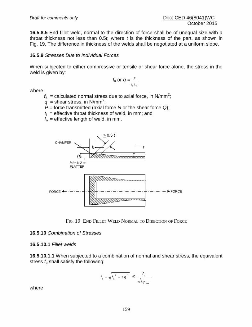
Draft for comments only Doc: CED 46(8041)WC October 2015
159
16.5.8.5 End fillet weld, normal to the direction of force shall be of unequal size with a throat thickness not less than 0.5t, where t is the thickness of the part, as shown in Fig. 19. The difference in thickness of the welds shall be negotiated at a uniform slope. 16.5.9 Stresses Due to Individual Forces When subjected to either compressive or tensile or shear force alone, the stress in the weld is given by:
fa or q =wt lt
P
where fa = calculated normal stress due to axial force, in N/mm2;
q = shear stress, in N/mm2; P = force transmitted (axial force N or the shear force Q);
tt = effective throat thickness of weld, in mm; and lw = effective length of weld, in mm.
16.5.10 Combination of Stresses 16.5.10.1 Fillet welds 16.5.10.1.1 When subjected to a combination of normal and shear stress, the equivalent stress fe shall satisfy the following:
22
3 qff ae
≤ mw
u
3
f
where
FORCE FORCE
FIG. 19 END FILLET WELD NORMAL TO DIRECTION OF FORCE
h:b=1: 2 or FLATTER
CHAMFER
> 0.5 t
h
b t

Draft for comments only Doc: CED 46(8041)WC October 2015
160
fa= normal stresses, compression or tension, due to axial force or bending moment (see 16.5.9), and q = shear stress due to shear force or tension (see 16.5.9).
16.5.10.1.2 Check for the combination of stresses need not be done for:
a) Side fillet welds joining cover plates and flange plates, and b) Fillet welds where sum of normal and shear stresses does not exceed fwd (see
16.5.7.1.1). 16.5.10.2 Butt welds 16.5.10.2.1 Check for the combination of stresses in butt welds need not be carried out provided that:
a) Butt welds are axially loaded, and b) In single and double bevel welds the sum of normal and shear stresses does not
exceed the design normal stress, and the shear stress does not exceed 50 percent of the design shear stress.
16.5.10.2.2 Combined bearing, bending and shear Where bearing stress, fbr is combined with bending (tensile or compressive), fb and shear stresses, q under the most unfavorable conditions of loading in butt welds, the equivalent stress, fe as obtained from the following formula, shall not exceed the values allowed for the parent metal:
2
brb
2
br
2
be3 qfffff
where
fe = equivalent stress; fb = calculated stress due to bending, in N/mm2;
fbr = calculated stress due to bearing, in N/mm2; and q = shear stress, in N/mm2.
16.5.11 Where a packing is welded between two members and is less than 6 mm thick, or is too thin to allow provision of adequate welds or to prevent buckling, the packing shall be trimmed flush with the edges of the element subject to the design action and the size of the welds along the edges shall be increased over the required size by an amount equal to the thickness of the packing. Otherwise, the packing shall extend beyond the edges and shall be fillet welded to the pieces between which it is fitted.

Draft for comments only Doc: CED 46(8041)WC October 2015
161
16.6 Design of Connections Each element in a connection shall be designed so that the structure is capable of resisting the design actions. Connections and adjacent regions of the members shall be designed by distributing the design action effects such that the following requirements are satisfied:
a) Design action effects distributed to various elements shall be in equilibrium with the design action effects on the connection,
b) Required deformations in the elements of the connections are within their deformations capacities,
c) All elements in the connections and the adjacent areas of members shall be capable of resisting the design action effects acting on them, and
d) Connection elements shall remain stable under the design action effects and deformations.
16.6.1 Connections can be classified as rigid, semi-rigid and flexible for the purpose of analysis and design as per the recommendation in Annex E. Connections with sufficient rotational stiffness may be considered as rigid. Examples of rigid connections include flush end-plate connection and extended end-plate connections. Connections with negligible rotational stiffness may be considered as flexible (pinned). Examples of flexible connections include single and double web angle connections and header plate connections. Where a connection cannot be classified as either rigid or flexible, it shall be assumed to be semi-rigid. Examples of semi-rigid connections include top and seat angle connection and top and seat angle with single/double web angles. 16.6.2 Design shall be on the basis of any rational method supported by experimental evidence. Residual stresses due to installation of bolts or welding normally need not be considered in statically loaded structures. Connections in cyclically loaded structures shall be designed considering fatigue as given in Section 6 (m). For earthquake load combinations, the connections shall be designed to withstand the calculated design action effects and exhibit required ductility as specified in Section 6 (l). 16.6.3 Beam and column splice shall be designed in accordance with the recommendation given in F-2 and F-3. 16.7 Minimum Design Action on Connection Connections carrying design action effects, except for lacing connections, connections of sag rods, purlins and girts, shall be designed to transmit the greater of:
a) the design action in the member; and b) The minimum design action effects expressed either as the value or the factor
times the member design capacity for the minimum size of member required by the strength limit state, specified as follows:

Draft for comments only Doc: CED 46(8041)WC October 2015
162
1) Connections in rigid construction a bending moment of at least 0.5 times the member design moment capacity
2) Connections to beam in simple construction a shear force of at least 0.15 times the member design shear capacity or 40 kN, whichever is lesser
3) Connections at the ends of tensile or compression member a force of at least 0.3 times the member design capacity
4) Splices in members subjected to axial tension a force of at least 0.3 times the member design capacity in tension 5) Splices in members subjected to axial compression – for ends prepared for full contact in accordance with 23.7.1, it shall be permissible to carry compressive actions by bearing on contact surfaces. When members are prepared for full contact to bear at splices, there shall be sufficient fasteners to hold all parts securely in place. The fasteners shall be sufficient to transmit a force of at least 0.15 times the member design capacity in axial compression. When members are not prepared for full contact, the splice material and its fasteners shall be arranged to hold all parts in line and shall be designed to transmit a force of at least 0.3 times the member design capacity in axial compression. In addition, splices located between points of effective lateral support shall be designed for the design axial force, Pd plus a design bending moment, not less than the design bending moment 0001sdd lPM where, ls is the distance
between points of effective lateral support. 6) Splices in flexural members – a bending moment of 0.3 times the member design capacity in bending. This provision shall not apply to splices designed to transmit shear force only. A splice subjected to a shear force only shall be designed to transmit the design shear force together with any bending moment resulting from the eccentricity of the force with respect to the centroid of the group. 7) Splices in members subject to combined actions – a splice in a member subject to a combination of design axial tension or design axial compression and design bending moment shall satisfy requirements in (iv), (v) and (vi) above, simultaneously. For earthquake load combinations, the design action effects specified in this section may need to be increased to meet the required behaviour of the steel frame and shall comply with Section 6 (l).

Draft for comments only Doc: CED 46(8041)WC October 2015
163
16.8 Intersections Members or components meeting at a joint shall be arranged to transfer the design actions between the parts, wherever practicable, with their centroidal axes meeting at a point. Where there is eccentricity at joints, the members and components shall be designed for the design bending moments which result due to eccentricity. The disposition of fillet welds to balance the design actions about the centroidal axis or axes for end connections of single angle, double angle and similar type members is not required for statically loaded members but is required for members, connection components subject to fatigue loading. Eccentricity between the centroidal axes of angle members and the gauge lines for their bolted end connections may be neglected in statically loaded members, but shall be considered in members and connection components subject to fatigue loading. 16.9 Choice of fasteners Where slip in the serviceability limit state is to be avoided in a connection, high-strength bolts in a friction-type joint, fitted bolts or welds shall be used. Where a joint is subjected to impact or vibration, either high strength bolts in a friction type joint or ordinary bolts with locking devices or welds shall be used.
16.10 Connection Components Connection components (cleats, gusset plates, brackets and the like) other than connectors, shall have their capacities assessed using the provisions of Sections 5(e), 5(f), 5(g), 5(h) and 5(i), as applicable. 16.11 Analysis of a Bolt/Weld Group 16.11.1 Bolt/Weld Group Subject to In-plane Loading 16.11.1.1 General method of analysis The design force in a bolt/weld or design force per unit length in a bolt/weld group subject to in-plane loading shall be determined in accordance with the following:
a) The connection plates shall be considered to be rigid and to rotate relative to each
other about a point known as the instantaneous centre of rotation of the group. b) In the case of a group subject to a pure couple only, the instantaneous centre of
rotation coincides with the group centroid. In the case of in-plane shear force applied at the group centroid, the instantaneous centre of the rotation is at infinity and the design force is uniformly distributed throughout the group. In all other

Draft for comments only Doc: CED 46(8041)WC October 2015
164
cases, either the results of independent analyses for a pure couple alone and for an in-plane shear force applied at the group centroid shall be superposed, or a recognized method of analysis shall be used.
c) The design force in a bolt or design force per unit length at any point in the group
shall be assumed to act at right angles to the radius from that point to the instantaneous centre, and shall be taken as proportional to that radius.
16.11.2 Bolt/Weld Group Subject to Out-of-Plane Loading 16.11.2.1 General method of analysis The design force of a bolt in bolt group or design force per unit length in the fillet weld group subject to out-of-plane loading shall be determined in accordance with the following:
a) Design force in the bolts or per unit length in the fillet weld group resulting from any shear force or axial force shall be considered to be equally shared by all bolts in the group or uniformly distributed over the length of the fillet weld group.
b) Design force resulting from a design bending moment shall be considered to vary
linearly with the distance from the relevant centroidal axes.
1) In bearing type of bolt group plates in the compression side of the neutral axis and only bolts in the tension side of the neutral axis may be considered for calculating the neutral axis and second moment of area.
2) In the friction grip bolt group only the bolts shall be considered in the calculation of neutral axis and second moment of area.
3) The fillet weld group shall be considered in isolation from the connected element; for the calculation of centroid and second moment of the weld length.
16.11.2.2 Alternative analysis The design force per unit length in a fillet weld/bolt group may alternatively be determined by considering the fillet weld group as an extension of the connected member and distributing the design forces among the welds of the fillet weld group so as to satisfy equilibrium between the fillet weld group and the elements of the connected member. 16.11.3 Bolt/Weld Group Subject to In-plane and Out-of-plane Loading 16.11.3.1 General method of analysis The design force in a bolt or per unit length of the weld shall be determined by the superposition of analysis for in-plane and out-of-plane cases discussed in 16.11.1 and 16.11.2.

Draft for comments only Doc: CED 46(8041)WC October 2015
165
16.11.3.2 Alternative analysis The design force in a bolt or per unit length in the fillet weld group may alternatively be determined by considering the fillet weld group as an extension of the connected member and proportioning the design force per bolt or unit length in the weld group to satisfy equilibrium between the bolt/weld group and the elements of the connected member. Force calculated in the most stressed bolt or highest force per unit length of the weld shall satisfy the strength requirements of 16.3, 16.4 or 16.5, as appropriate. 16.12 Lug Angles 16.12.1 Lug angles connecting outstanding leg of a channel-shaped member shall, as far as possible, be disposed symmetrically with respect to the section of the member. 16.12.2 In the case of angle members, the lug angles and their connections to the gusset or other supporting member shall be capable of developing a strength not less than 20 percent in excess of the force in the outstanding leg of the member, and the attachment of the lug angle to the main angle shall be capable of developing a strength not less than 40 percent in excess of the force in the outstanding leg of the angle. 16.12.3 In the case of channel members and the like, the lug angles and their connection to the gusset or other supporting member shall be capable of developing a strength of not less than 10 percent in excess of the force not accounted for by the direct connection of the member, and the attachment of the lug angles to the member shall be capable of developing 20 percent in excess of that force. 16.12.4 In no case shall fewer than two bolts, rivets or equivalent welds be used for attaching the lug angle to the gusset or other supporting member. 16.12.5 The effective connection of the lug angle shall, as far as possible terminate at the end of the member connected, and the fastening of the lug angle to the main member shall preferably start in advance of the direct connection of the member to the gusset or other supporting member. 16.12.6 Where lug angles are used to connect an angle member, the whole area of the member shall be taken as effective not withstanding the requirements of Section 6 (f) of this section.

Draft for comments only Doc: CED 46(8041)WC October 2015
166
SECTION 6 (k) WORKING STRESS DESIGN 17.1 General 17.1.1 General design requirements of Section 6 (c) shall apply in this section. 17.1.2 Methods of structural analysis of Section 6 (d) shall also apply to this section. The elastic analysis method shall be used in the working stress design. 17.1.3 The working stress shall be calculated applying respective partial safety factors for loads for service load/working load. 17.1.4 In load combinations involving wind or seismic loads, the permissible stresses in steel structural members may be increased by 33 percent. For anchor bolts and construction loads this increase shall be limited to 25 percent. Such an increase in allowable stresses should not be considered if the wind or seismic load is the major load in the load combination (such as acting along with dead load alone). 17.2 Tension Members 17.2.1 Actual Tensile Stress The actual tensile stress, ft on the gross area of cross-section, Ag of plates, angles and other tension members shall be less than or equal to the smaller value of permissible tensile stresses, fat, as given below: Actual tensile stress, ft = Ts / Ag
The permissible stress, fat is smallest of the values as obtained below:
a) As governed by yielding of gross section
fat = 0.6 fy
b) As governed by rupture of net section
i) Plates under tension
fat = 0.69 Tdn / Ag
ii) Angles under tension
fat = 0.69 Tdn / Ag
Draft for comments only Doc: CED 46(8041)WC October 2015
167
c) As governed by block shear fat = 0.69 Tdb / Ag
where
Ts = actual tension under working (service) load, Ag = gross area, Tdn = design strength in tension of respective plate/angle calculated in accordance with 12.3, and Tdb = design block shear strength in tension of respective plate/angle calculated in accordance with 12.4.
17.3 Compression Members 17.3.1 Actual Compressive Stress The actual compressive stress, fc at working (service) load, Ps of a compression member shall be less than or equal to the permissible compressive stress, fac as given below: Actual compressive stress, fc = Ps / Ae
The permissible compressive stress, fac = 0.60 fcd
where Ae = effective sectional area as defined in 13.3.2, and fcd = design compressive stress as defined in 13.1.2.1 (for angles see 13.5.1.2),
calculated without the partial safety factor, m0.
17.3.2 Design Details Design of the compression members shall conform to 13.3. 17.3.3 Column Bases The provisions of 13.4 shall be followed for the design of column bases, except that the thickness of a simple column base, ts shall be calculated as:
bss
fbawt /3.0322
where w = uniform pressure from below on the slab base due to axial compression; a, b = larger and smaller projection of the slab base beyond the rectangle circumscribing the column, respectively; and fbs = permissible bending stress in column base equal to 0.75 fy.

Draft for comments only Doc: CED 46(8041)WC October 2015
168
17.3.4 Angle Struts Provisions of 13.5 shall be used for design of angle struts, except that the limiting actual stresses shall be calculated in accordance with 17.3.1. 17.3.5 Laced and Battened Columns The laced and battened columns shall be designed in accordance with 13.6 and 13.7, except that the actual stresses shall be less than the permissible stresses given in 17.3.1. 17.4 Members Subjected to Bending 17.4.1 Bending Stresses The actual bending tensile and compressive stresses, fbt, fbc at working (service) load moment, Ms of a bending member shall be less than or equal to the permissible bending stresses, fabt, fabc respectively, as given herein. The actual bending stresses shall be calculated as:
fbc = Ms / Zec and fbt = Ms / Zet
The permissible bending stresses, fabc or fabt shall be the smaller of the values obtained from the following:
a) Laterally supported beams and beams bending about the minor axis:
i) Plastic and compact sections
fabc or fabt = 0.66 fy
ii) Semi-compact sections
fabc or fabt = 0.60 fy
b) Laterally unsupported beams subjected to major axis bending:
fabc = 0.60 Md / Zec
fabt = 0.60 Md / Zet
c) Plates and solid rectangles bending about minor axis :
fabc = fabt = 0.75fy

Draft for comments only Doc: CED 46(8041)WC October 2015
169
where Zec, Zet = elastic section modulus for the cross section with respect to extreme compression and tension fibres, respectively;
fy = yield stress of the material; and Md = design bending strength of a laterally unsupported beam bent about major axis, calculated in accordance with 14.2.2.
17.4.2 Shear Stress in Bending Members
The actual shear stress, b at working load, Vs of a bending member shall be less than
or equal to the permissible shear stress, ab given below:
Actual shear stress, b = Vs / Av The permissible shear stress is given by: a) When subjected to pure shear:
ab = 0.40 fy
b) When subjected to shear buckling (see 14.4.2.1):
ab = 0.70 Vn / Av
where
Vn = design shear strength as given in 14.4.2.2 (a), and Av = shear area of the cross-section as given in 14.4.1.
17.4.3 Plate Girder Provisions of 14.3, 14.4, 14.5, 14.6 and 14.7 shall apply, for the design of plate girder, except that the allowable stresses shall conform to 17.4.1 and 17.4.2. 17.4.4 Box Girder In design of box girder the provisions of 14.8 shall apply, except that the allowable bending stresses shall conform to 17.4.1. 17.5 Combined Stresses 17.5.1 Combined Bending and Shear Reduction in allowable moment need not be considered under combined bending and shear.

Draft for comments only Doc: CED 46(8041)WC October 2015
170
17.5.2 Combined Bending and Axial Force Members subjected to combined axial compression and bending shall be so proportioned to satisfy the following requirements: a) Member stability requirement:
;0.16.0
abcz
bczLT
abcy
bcymy
y
acy
c
f
fK
f
fCK
f
f
0.16.0
abcz
bczmzz
abcy
bcymy
y
acz
c
f
fCK
f
fCK
f
f
where Cmy, Cmz = equivalent uniform moment factor as per Table 18, fc = applied axial compressive stress under service load, fbcy, fbcz = applied compressive stresses due to bending about the major (y) and minor (z) axis of the member, respectively, facy, facz = allowable axial compressive stress as governed by buckling about minor (y) and major (z) axis, respectively, fabcy, fabcz = allowable bending compressive stresses due to bending about minor (y) and major (z) axes of the cross-section (see 17.4),
Ky = 1 + (λy - 0.2)ny ≤ 1 + 0.8 ny, Kz = 1 + (λz - 0.2)nz ≤ 1 + 0.8 nz,
125.0
1.01
mLT
yLT
C
n
KLT = 25.0
1.0
mLT
y
C
n,
where ny, nz = ratio of actual applied axial stress to the allowable axial stress for buckling about the y and z axis, respectively, CMLT = equivalent uniform moment factor, and λLT = non-dimensional slenderness ratio (see 14.2.2).
b) Member strength requirement At a support the values fabcy and fabcz shall be calculated using laterally supported member and shall satisfy:

Draft for comments only Doc: CED 46(8041)WC October 2015
171
0.16.0
abcz
bcz
abcy
bcy
y
c
f
f
f
f
f
f
17.5.3 Combined Bending and Axial Tension
Members subjected to both axial tension and bending shall be proportioned so that the following condition is satisfied:
0.1
abtz
btz
abty
bty
at
t
f
f
f
f
f
f
where fabty, fabtz = permissible tensile stresses under bending about minor (y) and major (z) axis when bending alone is acting, as given in 17.4.1. 17.5.4 Combined Bearing, Bending and Shear Stresses Where a bearing stress is combined with tensile or compressive stress, bending and shear stresses under the most unfavourable conditions of loading, the equivalent stress, fe obtained from the following formula, shall not exceed 0.9fy
2
bpb
2
p
2
be 3 fffff
where
b
= actual shear stress,
ft = actual tensile stress, fb = actual bending stress, fy = yield stress, and fp = actual bearing stress. The value of permissible bending stresses fbcy and fbcz to be used in the above formula shall each be lesser of the values of the maximum allowable stresses fabc and fabt in bending about appropriate axis. 17.6 Connections 17.6.1 All design provisions of SECTION 6 (j), except for the actual and permissible stress calculations, shall apply. 17.6.2 Actual Stresses in Fasteners 17.6.2.1 Actual stress in bolt in shear, fsb should be less than or equal to permissible stress of the bolt, fasb as given below:

Draft for comments only Doc: CED 46(8041)WC October 2015
172
The actual stress in bolt in shear, fsb = Vsb / Asb The permissible stress in bolt in shear, fasb = 0.60 Vnsb / Asb where Vsb = actual shear force under working (service) load, Vnsb = nominal shear capacity of the bolt as given in 16.3.3, and Asb = nominal plain shank area of the bolt. 17.6.2.2 Actual stress of bolt in bearing on any plate, fpb should be less than or equal to the permissible bearing stress of the bolt/plate, fapb as given below: Actual stress of bolt in bearing on any plate, fpb = Vsb / Apb The permissible bearing stress of the bolt/plate, fapb = 0.60 Vnpb / Apb
where Vnpb = nominal bearing capacity of a bolt on any plate as given in 16.3.4, and Apb = nominal bearing area of the bolt on any plate. 17.6.2.3 Actual tensile stress of the bolt, ftb should be less than or equal to permissible tensile stress of the bolt, fatb as given below: Actual tensile stress of the bolt, ftb = Ts / Asb
The permissible tensile stress of the bolt, fatb = 0.60 Tnb /Asb
where Ts = tension in bolt under working (service) load, Tnb = design tensile capacity of a bolt as given in 16.3.5, and Asb = nominal plain shank area of the bolt. 17.6.2.4 Actual compressive or tensile or shear stress of a weld, fw should be less than or equal to permissible stress of the weld, faw as given below: The permissible stress of the weld, faw = 0.6 fwn
where fwn = nominal shear capacity of the weld as calculated in 16.5.7.1.1. 17.6.2.5 If the bolt is subjected to combined shear and tension, the actual shear and axial stresses calculated in accordance with 17.6.2.1 and 17.6.2.3 do not exceed the respective permissible stresses fasb and fatb and the expression given below should satisfy:

Draft for comments only Doc: CED 46(8041)WC October 2015
173
0.1
22
atb
tb
asb
sb
f
f
f
f
where
fsb, ftb = actual shear and tensile stresses respectively, and fasb, fatb = permissible shear and tensile stresses respectively.
17.6.3 Stresses in Welds 17.6.3.1 Actual stresses in the throat area of fillet welds shall be less than or equal to permissible stresses, faw as given below:
faw = 0.4 fy
17.6.3.2. Actual stresses in the butt welds shall be less than the permissible stress as governed by the parent metal welded together.
SECTION 6 (l) DESIGN AND DETAILING FOR EARTHQUAKE LOADS
18 DESIGN AND DETAILING FOR EARTHQUAKE LOADS
18.1 General
Steel frames shall be so designed and detailed as to give them adequate strength, stability and ductility to resist severe earthquakes in all zones classified in 5 of Section 1 of Part 6 without collapse. Frames, which form a part of the gravity load resisting system but are not intended to resist the lateral earthquake loads, need not satisfy the requirements of this section, provided they can accommodate the resulting deformation without premature failure.
18.2 Load and Load Combinations
18.2.1 Earthquake loads shall be calculated as per 5 of Section 1 of Part 6, except that the reduction factors recommended in 18.3 may be used.
18.2.2 In the limit state design of frames resisting earthquake loads, the load combinations shall conform to Table 4.

Draft for comments only Doc: CED 46(8041)WC October 2015
174
18.2.3 In addition the following load combination shall be considered as required in 18.5.1.1, 18.7.3.1, and 18.11.2.2:
a) 1.2 Dead Load (DL)+ 0.5 Live Load (LL) ± 2.5 Earthquake Load (EL); and
b) 0.9 Dead Load (DL) ± 2.5 Earthquake Load (EL).
NOTE: The above combinations need not be considered for the design forces of members under combined axial forcé and bending moments.
18.3 Response Reduction Factor
For structures designed and detailed as per the provision of this section, the response reduction factors specified in Table 23 may be used in conjunction with the provision in 5 of Section 1 of Part 6 for calculating the design earthquake forces.
Table 23 Response Reduction Factor, R, for Building System
(Clause 18.3)
SI No.
(1)
Lateral Load Resisting System
(2)
R
(3)
i)
ii)
Braced Frame Systems:
a) Ordinary Concentrically Braced Frames (OCBF) b) Special Concentrically Braced Frame (SCBF) c) Eccentrically Braced Frame (EBF)
Moment Frame System:
a) Ordinary Moment Frame (OMF) b) Special Moment Frame (SMF)
Non-ductile frames
4 4.5
5
4 5 1.5
The braced and moment resisting frames can be designed as non-ductile frames, if they have height to span ratio not exceeding 1.0, such as in industrial buildings. Such frames need not meet the ductility requirements of other types of frames as specified in sections 18.4 to 18.12.
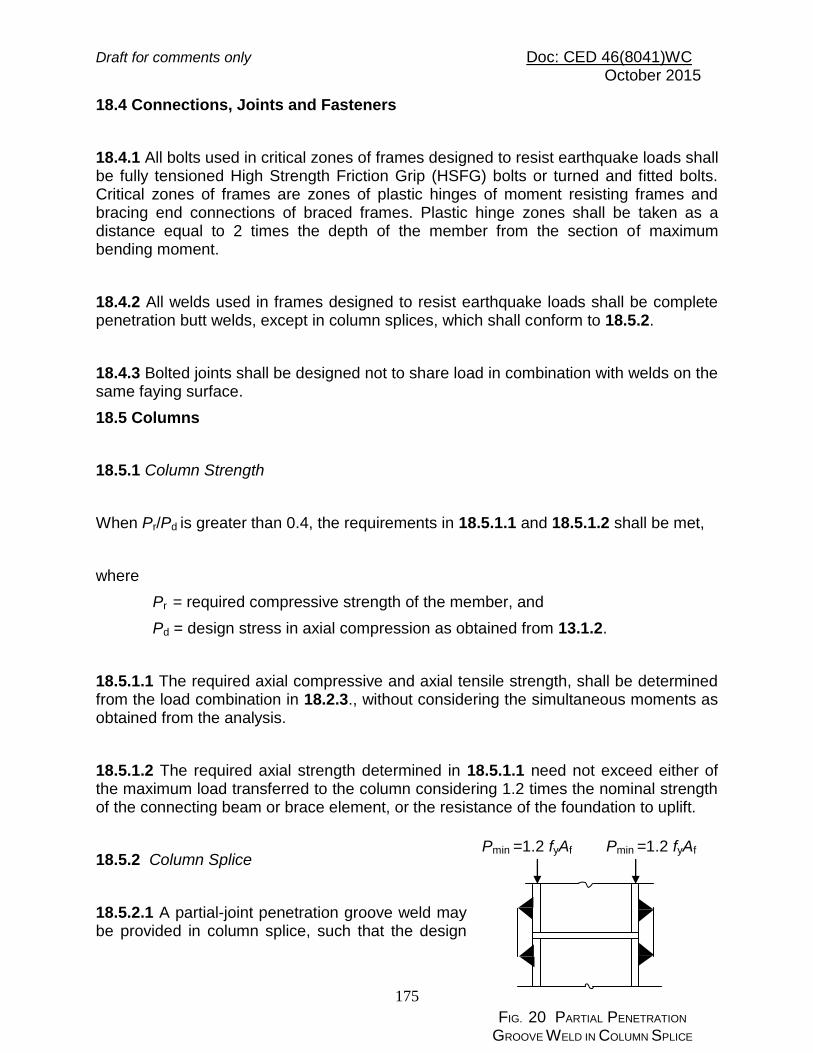
Draft for comments only Doc: CED 46(8041)WC October 2015
175
18.4 Connections, Joints and Fasteners
18.4.1 All bolts used in critical zones of frames designed to resist earthquake loads shall be fully tensioned High Strength Friction Grip (HSFG) bolts or turned and fitted bolts. Critical zones of frames are zones of plastic hinges of moment resisting frames and bracing end connections of braced frames. Plastic hinge zones shall be taken as a distance equal to 2 times the depth of the member from the section of maximum bending moment.
18.4.2 All welds used in frames designed to resist earthquake loads shall be complete penetration butt welds, except in column splices, which shall conform to 18.5.2.
18.4.3 Bolted joints shall be designed not to share load in combination with welds on the same faying surface.
18.5 Columns
18.5.1 Column Strength
When Pr/Pd is greater than 0.4, the requirements in 18.5.1.1 and 18.5.1.2 shall be met,
where
Pr = required compressive strength of the member, and
Pd = design stress in axial compression as obtained from 13.1.2.
18.5.1.1 The required axial compressive and axial tensile strength, shall be determined from the load combination in 18.2.3., without considering the simultaneous moments as obtained from the analysis.
18.5.1.2 The required axial strength determined in 18.5.1.1 need not exceed either of the maximum load transferred to the column considering 1.2 times the nominal strength of the connecting beam or brace element, or the resistance of the foundation to uplift.
18.5.2 Column Splice
18.5.2.1 A partial-joint penetration groove weld may be provided in column splice, such that the design
Pmin =1.2 fyAf Pmin =1.2 fyAf
FIG. 20 PARTIAL PENETRATION GROOVE WELD IN COLUMN SPLICE
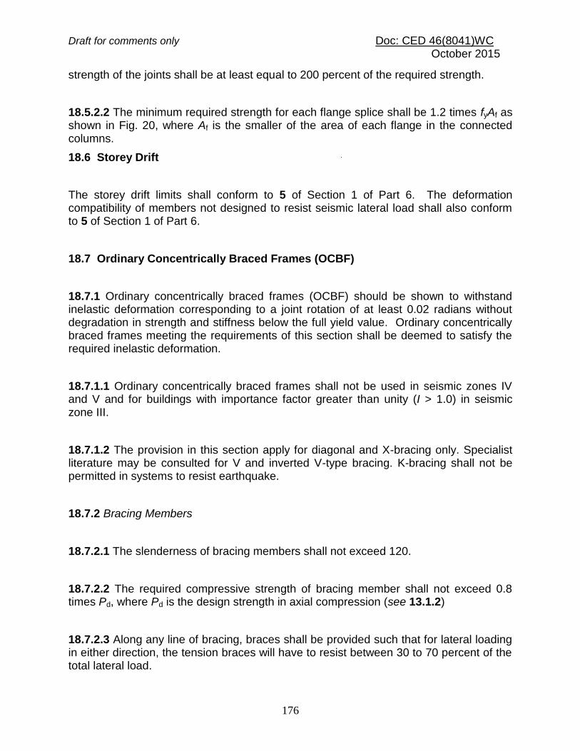
Draft for comments only Doc: CED 46(8041)WC October 2015
176
strength of the joints shall be at least equal to 200 percent of the required strength.
18.5.2.2 The minimum required strength for each flange splice shall be 1.2 times fyAf as shown in Fig. 20, where Af is the smaller of the area of each flange in the connected columns.
18.6 Storey Drift
The storey drift limits shall conform to 5 of Section 1 of Part 6. The deformation compatibility of members not designed to resist seismic lateral load shall also conform to 5 of Section 1 of Part 6.
18.7 Ordinary Concentrically Braced Frames (OCBF)
18.7.1 Ordinary concentrically braced frames (OCBF) should be shown to withstand inelastic deformation corresponding to a joint rotation of at least 0.02 radians without degradation in strength and stiffness below the full yield value. Ordinary concentrically braced frames meeting the requirements of this section shall be deemed to satisfy the required inelastic deformation.
18.7.1.1 Ordinary concentrically braced frames shall not be used in seismic zones IV and V and for buildings with importance factor greater than unity (I > 1.0) in seismic zone III.
18.7.1.2 The provision in this section apply for diagonal and X-bracing only. Specialist literature may be consulted for V and inverted V-type bracing. K-bracing shall not be permitted in systems to resist earthquake.
18.7.2 Bracing Members
18.7.2.1 The slenderness of bracing members shall not exceed 120.
18.7.2.2 The required compressive strength of bracing member shall not exceed 0.8 times Pd, where Pd is the design strength in axial compression (see 13.1.2)
18.7.2.3 Along any line of bracing, braces shall be provided such that for lateral loading in either direction, the tension braces will have to resist between 30 to 70 percent of the total lateral load.

Draft for comments only Doc: CED 46(8041)WC October 2015
177
18.7.2.4 Bracing cross-section can be plastic, compact or semi-compact, but not slender, as defined in 9.7.2.
18.7.2.5 For all built-up braces, the spacing of tack fasteners shall be such that the unfavourable slenderness ratio of individual element, between such fasteners, shall not exceed 0.4 times the governing slenderness ratio of the brace itself. Bolted connections shall be avoided within the middle one-fourth of the clear brace length (0.25 times the length in the middle).
18.7.2.6 The bracing members shall be designed so that gross area yielding (see 12.2) and not the net area rupture (see 12.3) would govern the design tensile strength.
18.7.3 Bracing Connections
18.7.3.1 End connections in bracings shall be designed to withstand the minimum of the following:
a) A tensile force in the bracing equal to 1.2 fy Ag;
b) Force in the brace due to load combinations in 18.2.3; and
c) Maximum force that is transferred to the brace by the system, based on analysis.
18.7.3.2 The connection should be checked for tension rupture and block shear under the load determined in 18.7.3.1.
18.7.3.3 The connection shall be designed to withstand a moment of 1.2 times the full plastic moment of the braced section about the buckling axis.
18.7.3.4 Gusset plates shall be checked for buckling out of their plane.
18.8 Special Concentrically Braced Frames (SCBF)
18.8.1 Special concentrically braced frames (SCBF) should be shown to withstand inelastic deformation corresponding to a joint rotation of at least 0.04 radians without degradation in strength and stiffness below the full yield value. Special concentrically braced frames meeting the requirements of this section shall be deemed to satisfy the required inelastic deformation.

Draft for comments only Doc: CED 46(8041)WC October 2015
178
18.8.1.1 Special concentrically braced frames (SCBF) may be used in any seismic zone (see 5 of Section 1 of Part 6) and for any building (importance-factor value).
18.8.1.2 The provision in this section apply for diagonal and X-bracing only. Specialist literature may be consulted for V and inverted-V type bracing. K bracing shall not be permitted in system to resist earthquake.
18.8.2 Bracing Members
18.8.2.1 Bracing members shall be made of E250B steel of the accepted standard [6-6(6)] or of steel having Charpy V-notch energy not less than 27J at the minimum design temperature.
18.8.2.2 The slenderness of bracing members shall not exceed 160 (except hanger elements).
18.8.2.3 The required compressive strength of bracing member shall not exceed the design strength in axial compression Pd (see 13.1.2).
18.8.2.4 Along any line of bracing, braces shall be provided such that for lateral loading in either direction, the tension braces will resist between 30 to 70 percent of the load.
18.8.2.5 Braced cross-section shall be plastic as defined in 9.7.2.
18.8.2.6 In built-up braces, the spacing of tack connections shall be such that the slenderness ratio of individual element between such connections shall not exceed 0.4 times the governing slenderness ratio of the brace itself. Bolted connection shall be avoided within the middle one-fourth of the clear brace length (0.25 times the length in the middle).
18.8.2.7 The bracing members shall be designed so that gross area yielding (see 12.2) and not the net area rupture (see 12.3) would govern the design tensile strength.

Draft for comments only Doc: CED 46(8041)WC October 2015
179
18.8.3 Bracing Connections
18.8.3.1 Bracing end connections shall be designed to withstand the minimum of the following:
a) A tensile force in the bracing equal to 1.1 fyAg; and b) Maximum force that can be transferred to the brace by the system.
18.8.3.2 The connection should be checked for tension rupture and block shear under the load determined in 18.8.3.1.
18.8.3.3 The connection shall be designed to withstand a moment of 1.2 times the full plastic moment of the braced section about the critical buckling axis.
18.8.3.4 Gusset plates shall be checked for buckling out of their plane.
18.8.4 Column
18.8.4.1 The column sections used in special concentrically braced frames (SCBF) shall be plastic as defined in 9.7.2.
18.8.4.2 Splices shall be located within the middle one-third of the column clear height. Splices shall be designed for the forces that can be transferred to it. In addition, splices in columns shall be designed to develop at least the nominal shear strength of the smaller connected member and 50 percent of the nominal flexural strength of the smaller connected section.
18.9 Eccentrically Braced Frames (EBF)
Eccentrically braced frames (EBF) shall be designed in accordance with specialist literature.
18.10 Ordinary Moment Frames (OMF)
18.10.1 Ordinary moment frames (OMF) should be shown to withstand inelastic deformation corresponding to a joint rotation of 0.02 radians without degradation in

Draft for comments only Doc: CED 46(8041)WC October 2015
180
strength and stiffness below the full yield value (Mp). Ordinary moment frames meeting the requirements of this section shall be deemed to satisfy the required inelastic deformation.
18.10.1.1 Ordinary moment frames (OMF) shall not be used in seismic zones IV and V and for buildings with importance factor greater than unity (I >1.0) in seismic zone III.
18.10.2 Beam-to-Column Joints and Connections
Connections are permitted to be rigid or semi-rigid moment connections and should satisfy the criteria in 18.10.2.1 to 18.10.2.5.
18.10.2.1 Rigid moment connections should be designed to withstand a moment of at least 1.2 times of either the full plastic moment of the connected beam or the maximum moment that can be delivered by the beam to the joint due to the induced weakness at the ends of the beam, whichever is less.
18.10.2.2 Semi-rigid connections should be designed to withstand either a moment of at least 0.5 times the full plastic moment of the connected beam or the maximum moment that can be delivered by the system, whichever is less. The design moment shall be achieved within a rotation of 0.01 radians. The information given in Annex E may be used for checking.
18.10.2.3 The stiffness and strength of semi-rigid connections shall be accounted for in the design and the overall stability of the frame shall be ensured.
18.10.2.4 The rigid and semi-rigid connections should be designed to withstand a shear resulting from the load combination 1.2DL + 0.5LL plus the shear corresponding to the design moment defined in 18.10.2.1 and 18.10.2.2, respectively.
18.10.2.5 In rigid fully welded connections, continuity plates (tension stiffener, see 14.7) of thickness equal to or greater than the thickness of the beam flange shall be provided and welded to the column flanges and web.
18.11 Special Moment Frames (SMF)
18.11.1 Special moment frames (SMF) shall be made of E250B steel of the accepted standard [6-6(6)] or of steel having Charpy V-notch energy, E > 27J and should be

Draft for comments only Doc: CED 46(8041)WC October 2015
181
shown to withstand inelastic deformation corresponding to a joint rotation of 0.04 radians without degradation in strength and stiffness below the full yield value (Mp). Special moment frames meeting the requirements of this section shall be deemed to satisfy the required inelastic deformation.
18.11.1.1 Special moment frames (SMF) may be used in any seismic zone (see 5 of Section 1 of Part 6) and for any buildings (importance-factor values).
18.11.2 Beam-to-Column Joints and Connections
18.11.2.1 All beam-to-column connections shall be rigid (see Annex E) and designed to withstand a moment of at least 1.2 times the full plastic moment of the connected beam. When a reduced beam section is used, its minimum flexural strength shall be at least equal to 0.8 times the full plastic moment of the unreduced section.
18.11.2.2 The connection shall be designed to withstand a shear resulting from the load combination 1.2DL + 0.5LL plus the shear resulting from the application of 1.2Mp in the same direction, at each end of the beam (causing double curvature bending). The shear strength need not exceed the required value corresponding to the load combination in 18.2.3.
18.11.2.3 In column strong axis connections (beam and column web in the same plane), the panel zone shall be checked for shear buckling in accordance with 14.4.2 at the design shear defined in 18.11.2.2. Column web doubler plates or diagonal stiffeners may be used to strengthen the web against shear buckling.
18.11.2.4 The individual thickness of the column webs and doubler plates, shall satisfy the following:
90/)(pp
bdt
where
t = thickness of column web or doubler plate,
dp = panel-zone depth between continuity plates (see Fig. 21), and
bp = panel-zone width between column flanges.

Draft for comments only Doc: CED 46(8041)WC October 2015
182
FIG. 21 CONTINUITY PLATES
18.11.2.5 Continuity plates (tension stiffener) (see 14.7) shall be provided in all strong axis welded connections except in end plate connection.
18.11.3 Beam and Column Limitation
18.11.3.1 Beam and column sections shall be either plastic or compact as defined in 9.7.2. At potential plastic hinge locations, they shall necessarily be plastic.
18.11.3.2 The section selected for beams and columns shall satisfy the following relation:
2.1
pb
pc
M
M
where
pcM = sum of the moment capacity in the column above and below
the beam centreline; and
pbM = sum of the moment capacity in the beams at the intersection of
the beam and column centrelines.
dp
bp
Continuity
plate

Draft for comments only Doc: CED 46(8041)WC October 2015
183
In tall buildings, higher mode effects shall be accounted for in accordance with specialist literature.
18.11.3.3 Lateral support to the column at both top and bottom beam flange levels shall be provided so as to resist at least 2 percent of the beam flange strength, except for the case described in 18.11.3.4.
18.11.3.4 A plane frame designed as non-sway in the direction perpendicular to its plane, shall be checked for buckling, under the load combination as specified in 18.5.1.1..
18.12 Non Ductile Braced and Moment Resisting Frames
Frames which do not meet the ductility requirements of the sections 18.4 to 18.12 requirements and designed as per the Response reduction factor for non-ductile frames specified in table 23 shall be classified as non-ductile frames. These frames shall have height to span ratio not exceeding 1.0, such as in industrial buildings.
18.13 Column Bases
18.13.1 Fixed column bases and their anchor bolts should be designed to withstand a moment of 1.2 times the full plastic moment capacity of the column section. The anchor bolts shall be designed to withstand the combined action of shear and tension as well as prying action, if any.
18.13.2 Both fixed and hinged column bases shall be designed to withstand the full shear under any load case or 1.2 times the shear capacity of the column section, whichever is higher.
SECTION 6(m) FATIGUE 19.1 General Structure and structural elements subject to loading that could lead to fatigue failure shall be designed against fatigue as given in this section. This shall however not cover the following:
a) Corrosion fatigue, b) Low cycle (high stress) fatigue,

Draft for comments only Doc: CED 46(8041)WC October 2015
184
c) Thermal fatigue, d) Stress corrosion cracking, e) Effects of high temperature (> 150o C), and f) Effects of low temperature (< brittle transition temperature).
19.1.1 For the purpose of design against fatigue, different details (of members and connections) are classified under different fatigue class. The design stress range corresponding to various number of cycles, are given for each fatigue class. The requirements of this section shall be satisfied with, at each critical location of the structure subjected to cyclic loading, considering relevant number of cycles and magnitudes of stress range expected to be experienced during the life of the structure. 19.2 Design 19.2.1 Reference Design Condition The standard S-N curves for each detail category are given for the following conditions:
a) Detail is located in a redundant load path, wherein local failure at that detail alone will not lead to overall collapse of the structure.
b) Nominal stress history at the local point in the detail is estimated/evaluated by a conventional method without taking into account the local stress concentration effects due to the detail.
c) Load cycles are not highly irregular. d) Details are accessible for and subject to regular inspection. e) Structure is exposed to only mildly corrosive environment as in normal
atmospheric condition and suitably protected against corrosion (pit depth < 1 mm).
f) Structure is not subjected to temperature exceeding 150 °C. g) Transverse fillet or butt weld connects plates of thickness not greater
than 25 mm. 19.2.1.1 Thickness correction factor The values obtained from the standard S-N curve shall be modified by a
capacity reduction factor r, when plates greater than 25 mm in thickness are joined together by transverse fillet or butt welding, given by:
r = (25/tp)0.25 1.0
where tp = actual thickness in mm of the thicker plate being joined

Draft for comments only Doc: CED 46(8041)WC October 2015
185
No thickness correction is necessary when full penetration butt weld reinforcements are machined flush and proved free of defect through nondestructive testing. 19.2.1.2 Necessity for Fatigue Assessment
a) Fatigue assessment is not normally required for building structures except as follows:
i) Members supporting lifting or rolling loads, ii) Member subjected to repeated stress cycles from vibrating machinery, iii) Members subjected to wind induced oscillations of a large number of cycles in
life, and iv) Members subjected to crowd induced oscillations of a large number of cycles
in life.
b) No fatigue assessment is necessary if the following conditions are satisfied.
i) The highest normal stress range ff max satisfies
mftrfmax/27 f
ii) The highest shear stress range fmax satisfies
mftfmax/67
r
iii) The total number of actual stress cycles NSC, satisfies
3
feqmft
6
SC
27105
fN
r
where ffeq =equivalent constant amplitude stress range in MPa given by
3/1
5
j
5r
j
3
i
5
1
feq
n
fnfn
f
r
j
r
i
i
where
r
i
nn
1
i
fi, fj = stress ranges falling above and below the ffn, the stress range corresponding to the detail at 5 x 10⁶ number of life cycles.

Draft for comments only Doc: CED 46(8041)WC October 2015
186
19.2.2 Design Spectrum 19.2.2.1 Stress evaluation Design stress shall be determined by elastic analysis of the structure to obtain stress resultants and the local stresses may be obtained by a conventional stress analysis method. The normal and shear stresses shall be determined considering all design actions on the members, but excluding stress concentration due to the geometry of the detail. The stress concentration effect is accounted for in detail category classification (see Table 26). The stress concentration, however, not characteristic of the detail shall be accounted for separately in the stress calculation. In the fatigue design of trusses made of members with open sections, in which the end connections are not pinned, the stresses due to secondary bending moments shall be taken into account, unless the slenderness ratio (KL/r), of the member is greater than 40. In the determination of stress range at the end connections between hollow sections, the effect of connection stiffness and eccentricities may be disregarded, provided
a) The calculated stress range is multiplied by appropriate factor given in Table 24(a) in the case of circular hollow section connections and Table 24(b) in the case of rectangular hollow section connections.
b) The design throat thickness of fillet welds in the joints is greater than the wall thickness of the connected member.
19.2.2.2 Design stress spectrum In the case of loading events producing non-uniform stress range cycle, the stress spectrum may be obtained by a rational method, such as ‘rain flow counting’ or an equivalent method.
Table 24 (a) Multiplying Factors for Calculated Stress Range
(Circular Hollow Sections) (Clause 19.2.2.1)
Sl No.
(1)
Type of Connection
(2)
Chords
(3)
Verticals
(4)
Diagonals
(5) i) Gap
connections K type 1.5
1.0 1.3
N type 1.5
1.8 1.4

Draft for comments only Doc: CED 46(8041)WC October 2015
187
ii) Overlap connections
K type 1.5
1.0 1.2
N type 1.5 1.65 1.25
Table 24 (b) Multiplying Factors for Calculated Stress Range (Rectangular Hollow Sections)
(Clause 19.2.2.1)
Sl
No.
(1)
Types of Joint
(2)
Chords
(3)
Verticals
(4)
Diagonals
(5)
i) Gap connections
K type
1.5
1.0
1.5
N type 1.5
2.2 1.6
ii)
Overlap connections
K type 1.5
1.0 1.3
N type
1.5
2.0
1.4
19.2.3 Partial Safety Factors
19.2.3.1 Partial safety factor for actions and their effects (fft) Unless and otherwise the uncertainty in the estimation of the applied actions and their effects demand a higher value, the partial safety factor for loads in the evaluation of stress range in fatigue design shall be taken as 1.0.
19.2.3.2 Partial safety factor for fatigue strength (mft) Partial safety factor for strength is influenced by consequences of fatigue damage and level of inspection capabilities. 19.2.3.3 Based on consequences of fatigue failure, component details have been classified as given in the Table 25 and the corresponding partial safety factor for fatigue strength shall be used:
a) Fail-safe structural component/detail is the one where local failure of one component due to fatigue crack does not result in the failure of the structure due to availability of alternate load path (redundant system).

Draft for comments only Doc: CED 46(8041)WC October 2015
188
b) Non-fail-safe structural component/detail is the one where local failure of one component leads rapidly to failure of the structure due to its non-redundant nature.
Table 25 Partial Safety Factors for fatigue strength (mft) (Clause 19.2.3.3)
Sl No. Inspection and Access
Consequence of failure
Fail-safe
Non-fail-
safe (1) (2) (3) (4)
I)
Periodic inspection, maintenance and accessibility to detail is good
1.00 1.25
ii) Periodic inspection, maintenance and accessibility to detail is poor
1.15 1.35
19.3 Detail Category Tables 26 (a) to (d) indicate the classification of different details into various categories for the purpose of assessing fatigue strength. Details not classified in the table may be treated as the lowest detail category of a similar detail, unless superior fatigue strength is proved by testing and/or analysis. Holes in members and connections subjected to fatigue loading shall not be made a) using punching in plates having thickness greater than 12 mm unless he
holes are sub-punched and subsequently reamed to remove the affected material around the punched hole,
b) using gas cutting unless the holes are reamed to remove the material in the heat affected zone.
19.4 Fatigue Strength The fatigue strength of the standard detail for the normal or shear fatigue stress range, not corrected for thickness effects discussed in 19.4.1, is given below (see also Figs. 22 and 23):

Draft for comments only Doc: CED 46(8041)WC October 2015
189
a) Normal stress range
when 6105
SCN
3 6/105
SCfnfNff
when 8610105
SCN
5 6/105
SCNff
fnf
b) Shear stress
SCfnfN
5 6/105
where
ff, f = design normal and shear fatigue stress range of the detail, respectively, for life cycle of NSC , and
ffn,fn = normal and shear fatigue strength of the detail for 5 x10⁶ cycles, for the detail category (see Table 26).

Draft for comments only Doc: CED 46(8041)WC October 2015
190
Table 26 (a) Detail Category Classification, Group 1 Non-welded Details (ffn) (Clause 19.3)
Sl No.
Detail Category
Constructional Details
Illustration (see Note) Description
(1) (2) (3) (4)
i)
118
Rolled and extruded products i) Plates and flats (1)
ii) Rolled sections (2) iii) Seamless tubes (3)
Sharp edges, surface and rolling flaws to be removed by grinding in the direction of applied stress.
ii)
103
(i) Bolted connections (4) and (5) : Stress range
calculated on the gross section and on the net section. Unsupported one-sided cover plate connections shall be avoided or the effect of the eccentricity taken into account in calculating stresses
(ii) Material with gas-cut or sheared edges with no draglines
(6) : All hardened material and
visible signs of edge discontinuities to be removed by machining or grinding in the direction of applied stress.
iii)
92
Material with machine gas-cut edges with draglines or manual gas-cut material (7) : Corners and visible signs of edge discontinuities to be removed by grinding in the direction of the applied stress.
(2)
(3)
(
3
)
(1)
(4)
(5)
(6)
(7)

Draft for comments only Doc: CED 46(8041)WC October 2015
191
NOTE ― The arrow indicates the location and direction of the stresses acting in the basic material for which the stress range is to be calculated on a plane normal to the arrow.
______________________________________________________________________

Draft for comments only Doc: CED 46(8041)WC October 2015
192
Table 26 b) Detail Category Classification, Group 2 Welded
Details - not in Hollow Sections (ffn) (Clause 19.3)
_______________________________________________________________________
Sl No.
Detail Category
Constructional Details
Illustration (see Note) Description
i) 92
Welded plate I-section and box girders with continuous Longitudinal welds (8) & (9) : Zones of continuous automatic longitudinal fillet or butt welds carried out from both sides and all welds not having un-repaired stop-start positions.
ii) 83
Welded plate I-section and box girders with continuous longitudinal welds (10) & (11) : Zones of continuous automatic butt welds made from one side only with a continuous backing bar and all welds not having un-repaired stop-start positions. (12) : Zones of continuous longitudinal fillet or butt welds carried out from both sides but containing stop-start positions. For continuous manual longitudinal fillet or butt welds carried out from both sides, use Detail Category 92.
iii) 66
Welded plate I-section and box girders with continuous longitudinal welds (13) : Zones of continuous longitudinal welds carried out from one side only, with or without stop-start positions.
(8)
(9)
(10
)
(11
) (12
)
(13)

Draft for comments only Doc: CED 46(8041)WC October 2015
193
Table 26 (b) (continued) ____________________________________________________________________
Sl No.
Detail Category
Constructional Details
Illustration (see Note) Description
(1) (2) (3) (4)
iv)
59
Intermittent Longitudinal Welds (14) : Zones of intermittent longitudinal welds
v)
52
Intermittent Longitudinal Welds (15) : Zones containing cope holes in longitudinally welded T-joints. Cope hole not to be filled with weld.
vi)
83
Transverse Butt Welds (complete penetration) Weld run-off tabs to be used, subsequently removed and ends of welds ground flush in the direction of stress. Welds to be made from two sides. (16) : Transverse splices in plates, flats and rolled sections having the weld reinforcement ground flush to plate surface. 100 percent NDT inspection, and weld surface to be free of exposed porosity in the weld metal. (17) : Plate girders welded as in (16) before assembly. (18) :Transverse splices as in (16) with reduced or tapered
transition with taper 1:4
(14)
(15)
(16) (17)
(18)
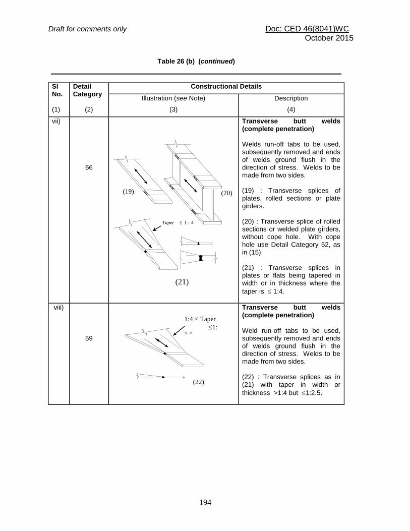
Draft for comments only Doc: CED 46(8041)WC October 2015
194
Table 26 (b) (continued)
Sl No.
Detail Category
Constructional Details
Illustration (see Note) Description
(1) (2) (3) (4)
vii)
66
Transverse butt welds (complete penetration) Welds run-off tabs to be used, subsequently removed and ends of welds ground flush in the direction of stress. Welds to be made from two sides. (19) : Transverse splices of plates, rolled sections or plate girders. (20) : Transverse splice of rolled sections or welded plate girders, without cope hole. With cope hole use Detail Category 52, as in (15). (21) : Transverse splices in plates or flats being tapered in width or in thickness where the
taper is 1:4.
viii)
59
Transverse butt welds (complete penetration) Weld run-off tabs to be used, subsequently removed and ends of welds ground flush in the direction of stress. Welds to be made from two sides. (22) : Transverse splices as in (21) with taper in width or
thickness >1:4 but 1:2.5.
(22)
1:4 < Taper
1:
2.5
(20)
(21)
(19)
4:1Taper

Draft for comments only Doc: CED 46(8041)WC October 2015
195
Table 26 (b) (continued) _______________________________________________________________________
Sl No.
Detail Category
Constructional Details
Illustration (see Note) Description
(1) (2) (3) (4)
ix)
52
Transverse butt welds (complete penetration) (23) : Transverse butt-welded splices made on a backing bar. The end of the fillet weld of the backing strip shall stop short by more than 10 mm from the edges of the stressed plate. (24) : Transverse butt welds as per (23) with taper on width or thickness <1:2.5.
x)
37
Transverse butt welds (complete penetration) (25) : Transverse butt welds as in (23) where fillet welds end closer than 10 mm to plate edge.
xi)
52
Cruciform joints with load-carrying welds (26) : Full penetration welds with intermediate plate NDT inspected and free of defects. Maximum misalignment of plates either side of joint to be < 0.15 times the thickness of intermediate plate.
xii)
41
(27)
(27) : Partial penetration or fillet welds with stress range calculated on plate area. (28) : Partial penetration or fillet welds with stress range calculated on throat area of weld.
27
(28)
(26)
(24)
> 10 mm
>10
mm
>10 mm
(23)
<10 mm
(25)
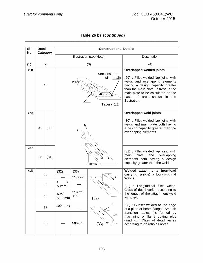
Draft for comments only Doc: CED 46(8041)WC October 2015
196
Table 26 b) (continued) _____________________________________________________________________
Sl No.
Detail Category
Constructional Details
Illustration (see Note) Description
(1) (2) (3) (4)
xiii)
46
Stresses area of main plate Taper < 1:2
Overlapped welded joints (29) : Fillet welded lap joint, with welds and overlapping elements having a design capacity greater than the main plate. Stress in the main plate to be calculated on the basis of area shown in the illustration.
xiv)
41 (30)
Overlapped weld joints (30) : Fillet welded lap joint, with welds and main plate both having a design capacity greater than the overlapping elements.
xv)
33 (31)
(31) : Fillet welded lap joint, with main plate and overlapping elements both having a design capacity greater than the weld.
xvi) 66
(32) (33)
Welded attachments (non-load carrying welds) - Longitudinal Welds (32) : Longitudinal fillet welds. Class of detail varies according to the length of the attachment weld as noted. (33) : Gusset welded to the edge of a plate or beam flange. Smooth transition radius (r), formed by machining or flame cutting plus grinding. Class of detail varies according to r/b ratio as noted.
1/3 r/b
59 l 50mm
52
50<l
100mm
1/6r/b <1/3
37
100mm<l
33 r/b<1/6
l
(32)
r
b (33)
t b
t
>10mm

Draft for comments only Doc: CED 46(8041)WC October 2015
197
xvii)
59
Welded attachments (34) : Shear connectors on base material (failure in base material).
(34)
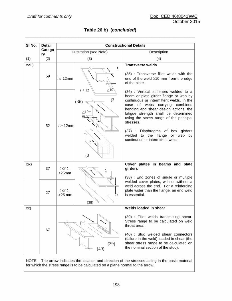
Draft for comments only Doc: CED 46(8041)WC October 2015
198
Table 26 b) (concluded) ___________________________________________________________________
Sl No. Detail
Category
Constructional Details
Illustration (see Note) Description
(1) (2) (3) (4)
xviii)
59
t 12mm
Transverse welds (35) : Transverse fillet welds with the
end of the weld 10 mm from the edge of the plate. (36) : Vertical stiffeners welded to a beam or plate girder flange or web by continuous or intermittent welds. In the case of webs carrying combined bending and shear design actions, the fatigue strength shall be determined using the stress range of the principal stresses. (37) : Diaphragms of box girders welded to the flange or web by continuous or intermittent welds.
52 t > 12mm
xix) 37
tf or tp
25mm
Cover plates in beams and plate girders (38) : End zones of single or multiple welded cover plates, with or without a weld across the end. For a reinforcing plate wider than the flange, an end weld is essential.
27 tf or tp
>25 mm
xx)
67
Welds loaded in shear (39) : Fillet welds transmitting shear. Stress range to be calculated on weld throat area. (40) : Stud welded shear connectors (failure in the weld) loaded in shear (the shear stress range to be calculated on the nominal section of the stud).
NOTE – The arrow indicates the location and direction of the stresses acting in the basic material for which the stress range is to be calculated on a plane normal to the arrow.
(40) (39)
(36)
>10m
m
t
t < 12
mm
t
>10
mm
(3
7)
(3
5)
t
tf
tp
(38)

Draft for comments only Doc: CED 46(8041)WC October 2015
199
Table 26 c) Detail Category Classification, Group 3 Bolts
(Clause 19.3)
Sl No.
Detail Category
Constructional Details
Illustration (see Note)
Description
(1) (2) (3) (4)
i)
83
(41)
Bolts in shear (8.8/TB Bolting category only) (41) : Shear stress range calculated on the minor diameter area of the bolt (Ac). Note: If the shear on the joint is insufficient to cause slip of the joint the shear in the bolt need not be considered in fatigue.
ii)
27
(42)
Bolts and threaded rods in tension (tensile stress to be calculated on the tensile stress area, At) (42) : Additional forces due to prying effects shall be taken into account. For tensional bolts, the stress range depends on the connection geometry. Note: In connections with tensioned bolts, the change in the force in the bolts is often less than the applied force, but this effect is dependent on the geometry of the connection. It is not normally required that any allowance for fatigue be made in calculating the required number of bolts in such connections.
NOTE ―The arrow indicates the location and direction of the stresses acting in the basic material for which the stress range is to be calculated on a plane normal to the arrow.
________________________________________________________________

Draft for comments only Doc: CED 46(8041)WC October 2015
200
Table 26d) Detail Category Classification, Group 4 Welded details – in hollow sections (ffn)
(Clause 19.3) _______________________________________________________________________
Sl No.
Detail Category
Constructional Details
Illustration (see Note) Description
(1) (2) (3) (4)
i)
103
(43)
Continuous automatic longitudinal welds (43) : No stop-starts, or as manufactured, proven free to detachable discontinuities.
ii) 66
(t 8 mm)
(44)
Transverse butt welds (44) : Butt-welded end-to-end connection of circular hollow sections. (Note: Height of the weld reinforcement less than 10% of weld with smooth transition to the plate surface. Welds made in flat position and proven free to detachable discontinuities).
52 (t < 8 mm)
iii) 52
(t 8 mm)
(45)
(45) : Butt-welded end-to-end connection of rectangular hollow sections
41 (t < 8 mm)
iv) 41
(t 8 mm)
(46)
Butt welds to intermediate plate (46) : Circular hollow sections, end-to-end butt-welded with an intermediate plate.
37 (t < 8 mm)
v) 37
(t 8 mm)
(47)
(47) Rectangular hollow sections, end-to-end butt welded with an intermediate plate 30
(t < 8 mm)
vi)
52
(48)
Welded attachemnts (non-load-carrying) (48) : Circular or rectangular hollow section, fillet welded to another section. Section width parallel to stress direction
100mm.
vii) 33 (t < 8 mm)
(49)
Fillet welds to intermediate plate (49) : Circular hollow sections, end-to-end fillet welded with an intermediate plate. 29
(t < 8 mm)
Section
Width
100
mm
t
t

Draft for comments only Doc: CED 46(8041)WC October 2015
201
viii) 29
(t 8 mm)
(50)
(50) : Rectangular hollow sections, end-to-end fillet welded with an intermediate plate.
27 (t < 8 mm)
NOTE ―The arrow indicates the location and direction of the stresses acting in the basic material for which the stress range is to be calculated on a plane normal to the arrow.
________________________________________________________________________
FIG. 22 S-N CURVE FOR NORMAL STRESS 19.5 Fatigue Assessment
The design fatigue strength for NSC life cycles (ffd, fd) may be obtained from the
standard fatigue strength for NSC cycles by multiplying with correction factor, r, for thickness, as mentioned in 19.2.1 and dividing by partial safety factor given in Table 25. 19.5.2 Stress Limitations 19.5.2.1 The maximum (absolute) value of the normal and shear stresses shall never
exceed the elastic limit (fy, y) for the material under cyclic loading.
105 2 3 4 5 6
106 2 3 4 5 6
107 2 3 4 5 6
108
UN
CO
RR
EC
TE
D
FA
TIG
UE
ST
RE
NG
TH
M
Pa.
10
100
1000
1.E+05 1.E+06 1.E+07 1.E+08
112
200
300
400
500
20
30
40
50
NUMBER OF STRESS CYCLES (NSC)
s= 3
s= 5
180
160 140
125
100 90 80 71 63 56 50 45
40
133
118
103 92 83 74 66
52
46 41 37 33
29 27
59
60
36
Constant Stress range
corresponding to 2106cycle
Constant normal stress range at
5 106 cycles (Detail category(ffn))
(NSC>5106)
(NSC<5106)
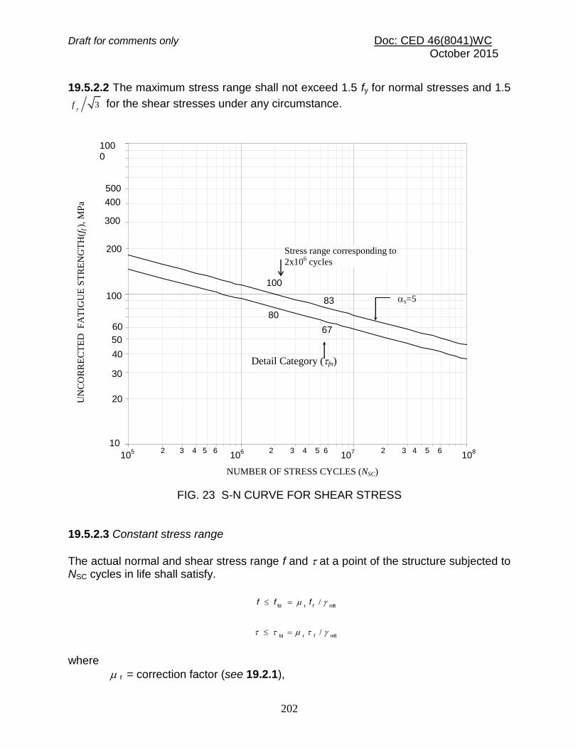
Draft for comments only Doc: CED 46(8041)WC October 2015
202
19.5.2.2 The maximum stress range shall not exceed 1.5 fy for normal stresses and 1.5
3y
f for the shear stresses under any circumstance.
FIG. 23 S-N CURVE FOR SHEAR STRESS
19.5.2.3 Constant stress range
The actual normal and shear stress range f and at a point of the structure subjected to NSC cycles in life shall satisfy.
mftrfd /
ffff
mftfrfd /
where
r = correction factor (see 19.2.1),
s=5
NUMBER OF STRESS CYCLES (NSC)
105 2 3 4 5 6 10
6 2 3 4 5 6 107 2 3 4 5 6 10
8
UN
CO
RR
EC
TE
D
FA
TIG
UE
ST
RE
NG
TH
(ff ),
MP
a
10
1000
30
40
50
60
200
300
400
500
20
100
Detail Category (fn)
67
83
Stress range corresponding to
2x10⁶ cycles
100
80
Draft for comments only Doc: CED 46(8041)WC October 2015
203
mf = partial safety factor against fatigue failure, given in Table 25, and
ff , f = normal and shear fatigue strength ranges for the actual life cycle, NSC, obtained from 19.4 . 19.5.2.4 Variable stress range
Fatigue assessment at any point in a structure, wherein variable stress ranges fi or i for ni number of cycles (i =1 to r ) are encountered, shall satisfy the following: a) For normal stress (f)
0.1
/105/1055
mffn
6
5
jj
3
mftfn
6
3
i
1
i
5
5
tr
r
rj
r
i
f
fn
f
fn
r
b) For shear stresses ()
5
mffn
6
1
5
i/105
t
r
i
in
Where r5 is the summation upper limit of all the normal stress ranges (fi) having
magnitude lesser than (r ffn /mft) for that detail and the lower limit of all the normal
stress ranges (fj) having magnitude greater than (r ffn /mft) for the detail. In the above
summation all normal stress ranges, fi, and shear stress ranges i having magnitude
less than 0.55r ffn, and 0.55r fn respectively may be disregarded.
SECTION 6(n) DESIGN ASSISTED BY TESTING 20 DESIGN ASSISTED BY TESTING 20.1 Need for Testing Testing of structures, members or components of structures is not required when designed in accordance with this standard. Testing may be accepted as an alternative to calculations or may become necessary in special circumstances. Testing of a structural system, member or component may be required to assist the design in the following cases:
a) When the calculation methods available are not adequate for the design of a particular structure, member or component, testing shall be undertaken in place of design by calculation or to supplement the design by calculation;
b) Where rules or methods for design by calculation would lead to uneconomical design, experimental verification may be undertaken to avoid conservative design;

Draft for comments only Doc: CED 46(8041)WC October 2015
204
c) When the design or construction is not entirely in accordance with sections of this standard, experimental verification is recommended;
d) When confirmation is required on the consistency of production of material, components, members or structures originally designed by calculations or testing;
e) When the actual performance of an existing structure capacity is in question, testing shall be used to confirm it.
20.1.1 Testing of structural system, member or component shall be of the following categories:
a) Proof testing The application of test loads to a structure, sub-structure, member or connection to ascertain the structural characteristics of only that specific unit.
b) Prototype testing Testing of structures, sub-structures, members or connections is done to ascertain the structural characteristics of a class of such structures, sub-structures members or connection, which are nominally identical to the units tested.
20.2 Types of Test 20.2.1 Acceptance Test This is intended as a non-destructive test for confirming structural performance. It should be recognized that the loading applied to certain structures might cause permanent distortions. Such effects do not necessarily indicate structural failure in acceptance test. However, the possibility of their occurrence should be agreed to before testing. The load for acceptance test, Ftest, a shall be determined from:
Ftest,a = (1.0 self weight) + (1.15 remainder of the permanent load) +
(1.25 variable load) The assembly shall satisfy the following criteria:
a) It shall demonstrate substantially linear behaviour under test loading, and b) On removal of the test load, the residual deflection shall not exceed 20 percent of
the maximum-recorded deflection.
If the above criteria are not satisfied the test may be repeated one more time only, when the assembly shall satisfy the following criteria:
a) It shall demonstrate substantially linear behaviour on the second application of test loading, and
b) Corresponding recorded residual deflection in the second test shall not exceed 10 percent of the maximum deflection during the test.

Draft for comments only Doc: CED 46(8041)WC October 2015
205
20.2.2 Strength Test Strength test is used to confirm the calculated resistance of a structure or component. Where a number of items are to be constructed to a common design, and one or more prototypes are tested to confirm their strength, the others may be accepted without any additional test, provided they are similar in all relevant respects to the prototype. Before carrying out the strength test, the specimen should first be subjected to and satisfy the acceptance test. Since the resistance of the assembly under test depends on the material properties, the actual yield strength of all the steel materials in the assembly shall be determined from coupon {test piece as defined in the accepted standard [6-6(7)]} tests . The mean value of the yield strength, fym, taken from such tests shall be determined with due regard to the importance of each element in the assembly. The strength test load Ftest, s (including self weight) shall be determined from:
yymdmistest, / ffFF
where fy = characteristic yield stress of the material as assumed in the design, Fd = factored design load for the ultimate limit state, and
mi = partial safety factor for the type of failure, as prescribed in this standard. At this load there shall be no failure by buckling or rupture of any part of the structure or component tested. On removal of the test load, the deflection should decrease by at least 20 percent of the maximum deflection at Ftest, s. 20.2.3 Test to Failure (Ultimate Strength Test) The objective of a test to failure is to determine the design resistance from the ultimate resistance. In this situation it is still desirable to carry out the acceptance and strength tests, before test to failure. Not less than three tests shall be carried out on nominally identical specimens. An estimate should be made of the anticipated ultimate resistance as a basis for such tests. During a test to failure, the loading shall first be applied in increments up to the strength test load. Subsequent load increments shall then be determined from consideration of the principal load deflection plot. The test load resistance, Ftest.R shall be determined as that load at which the specimen is unable to sustain any further increase in load. At this load, gross permanent distortion is likely to have occurred and in some cases such large gross deformation may define the test limit. If the deviation of any individual test result exceeds 10 percent of the mean value obtained for all the three tests, at least three more tests shall be carried out. When the deviation from the mean does not exceed 10 percent of the mean, the design resistance may be evaluated as given below:

Draft for comments only Doc: CED 46(8041)WC October 2015
206
a) When the failure is ductile, the design resistance, Fd may be determined from:
m0ymyMin test, /)/(9.0 ffFF d
where Ftest, Min = minimum test result from the tests to failure, fym = average yield strength as obtained from the material tests, and fy = characteristic yield stress of the grade of steel. b) In the case of a sudden (brittle) rupture type failure, the design resistance
may be determined from:
m1umuMin test,d /)/(9.0 ffFF
where fu = characteristic ultimate stress of the grade of steel used, and fum = average ultimate tensile strength of the material obtained from tests. c) In the case of a sudden (brittle) buckling type failure, the design resistance shall be
determined from:
m0ymyMin test,d /)/(75.0 ffFF
d) In ductile buckling type failure in which the relevant slenderness can be reliably assessed, the design resistance may be determined from:
m0ymmyMintest,d /)/(9.0 ffFF
where
= reduction factor for the relevant buckling curve, and
m = value of when the yield strength is fym.
20.2.4 Check Tests Where a component or assembly is designed on the basis of strength tests or tests to failure and a production run is carried out of such items, an appropriate number of samples (not less than two) shall be selected from each production batch at random for check tests. 20.2.4.1 The samples shall be carefully examined to ensure that they are similar in all respects to the prototype tested, particular attention being given to the following:

Draft for comments only Doc: CED 46(8041)WC October 2015
207
a) Dimensions of components and connections, b) Tolerance and workmanship, and c) Quality of steel used, checked with reference to mill test certificates.
20.2.4.2 Where it is not possible to determine either the variations or the effect of variations from the prototype, an acceptance test shall be carried out as a check test. 20.2.4.3 In this check test, the deflections shall be measured at the same positions as in the acceptance test of the prototype. The maximum measured deflection shall not exceed 120 percent of the deflection recorded during the acceptance test on the prototype and the residual deflection should not be more than 105 percent of that recorded for the prototype. 20.3 Test Conditions
a) Loading and measuring devices shall be calibrated in advance. b) The design of the test rig shall be such that:
i) Loading system adequately simulates the magnitude and distribution of the
loading, ii) It allows the specimen to perform in a manner representative of service
conditions, iii) Lateral and torsional restraint, if any, should be representative of those in
service, iv) Specimen should be free to deflect under load according to service condition, v) Loading system shall be able to follow the movements of the specimen
without interruption or abnormal restraints, vi) Inadvertent eccentricities at the point of application of the test loads and at
the supports are avoided.
c) Test load shall be applied to the unit at a rate as uniform as practicable. d) Deflections should be measured at sufficient points of high movements to ensure
that the maximum value is determined. e) If the magnitude of stresses in a specimen is to be determined, the strain at the
desired location may be measured and the corresponding stress calculated. f) Prior to any test, preliminary loading (not exceeding the characteristic values of the
relevant loads) may be applied and then removed, in order to set the test specimen on to the test rig.
20.4 Test Loading 20.4.1 Where the self-weight of the specimen is not representative of the actual permanent load in service, allowance for the difference shall be made in the calculation of test loads to be applied.

Draft for comments only Doc: CED 46(8041)WC October 2015
208
20.4.2 On the attainment of maximum load for either acceptance or strength tests, this load shall be maintained for at least 1 h. Reading of load and deflection shall be taken at intervals of 15 min and the loading shall be maintained constant until there is no significant increase in deflection during a 15 min period or until at least 1 h has elapsed. 20.4.3 The test load shall be equal to the design load for the relevant limit state in proof testing. 20.4.4 The test load in prototype testing shall be equal to the design load for the relevant limit state as multiplied by the appropriate factor given in Table 27. 20.5 Criteria for Acceptance 20.5.1 Acceptance for Strength The test structure, sub-structure, member or connection shall be deemed to comply with the requirements for strength if it is able to sustain the strength test load for at least 15 min. It shall then be inspected to determine the nature and extent of any damage incurred during the test. The effects of the damage shall be considered and if necessary appropriate repairs to the damaged parts carried out. 20.5.2 Acceptance for Serviceability The maximum deformation of the structure or member under the serviceability limit state test load shall be within the serviceability limit values appropriate to the structure.
Table 27 Factors to Allow for Variability of Structural Units
(Clause 20.4.4)
Sl No.
(1)
No. of Similar Units to be
Tested
(2)
For Strength Limit State
(3)
For Serviceability
Limit State
(4)
i) 1
1.5 1.2
ii) 2
1.4 1.2
iii) 3
1.3 1.2
iv) 4
1.3 1.1
v) 5
1.3 1.1
vi) 10
1.2 1.1
Draft for comments only Doc: CED 46(8041)WC October 2015
209
SECTION 6 (o) DURABILITY
21 DURABILITY
21.1 General
A durable steel structure is one that performs satisfactorily the desired function in the working environment under the anticipated exposure condition during its service life, without deterioration of the cross-sectional area and loss of strength due to corrosion. The material used, the detailing, fabrication, erection and surface protection measures should all address the corrosion protection and durability requirements.
21.2 Requirements for Durability
21.2.1 Shape, Size, Orientation of Members, Connections and Details
The design, fabrication and erection details of exposed structures should be such that good drainage of water is ensured. Standing pool of water, moisture accumulation and rundown of water for extended duration shall be avoided.
The details of connections should ensure that:
a) All exposed surfaces are easily accessible for inspection and maintenance, and b) All surfaces, not so easily accessible are completely sealed against ingress of moisture.
21.2.2 Exposure Condition
21.2.2.1 General environment
The general environment, to which a steel structure is exposed during its working life is classified into five levels of severity, as given in Table 28.

Draft for comments only Doc: CED 46(8041)WC October 2015
210
21.2.2.2 Abrasion
Specialist literature may be referred for durability of surfaces exposed to abrasive action as in machinery, conveyor belt support system, storage bins for grains or aggregates.
21.2.2.3 Exposure to sulphate attack
Appropriate coatings may be used when surfaces of structural steel are exposed to concentration of sulphates (SO3) in soil, ground water, etc.
When exposed to very high sulphate concentrations of more than 2 percent in soil and 5 percent in water, some form of lining such as polyethylene, polychloroprene sheet or surface coating based on asphalt, chlorinated rubber, epoxy or polymethane material should be used to completely avoid access of the solution to the steel surface.
Table 28 Environmental Exposure Conditions
(Clause 21.2.2.1)
Sl No.
Environmental Classifications
Exposure conditions
(1) (2) (3)
i) Mild Surfaces normally protected against exposure to weather or aggressive condition as in interior of buildings, except when located in coastal areas
ii) Moderate Structural steel surfaces:
a) exposed to condensation and rain b) continuously under water c) exposed to non-aggressive soil/groundwater d) sheltered from saturated salt air in coastal areas

Draft for comments only Doc: CED 46(8041)WC October 2015
211
iii) Severe Structural steel surfaces:
a) exposed to severe frequent rain b) exposed to alternate wetting and drying c) severe condensation d) completely immersed in sea water e) exposed to saturated salt air in coastal area
iv) Very severe Structural steel surface exposed to:
a) sea water spray b) corrosive fumes c) aggressive sub-soil or ground water
v) Extreme Structural steel surfaces exposed to:
a) tidal zones and splash zones in the sea b) aggressive liquid or solid chemicals
21.2.3 Corrosion Protection Methods
The methods of corrosion protection are governed by actual environmental conditions as specified in good practices [6-6(41)]. The main corrosion protection methods are given below:
a) Controlling the electrode potential, b) Inhibitors, and c) Inorganic/metal coatings or organic/paint systems.
21.2.4 Surface Protection
21.2.4.1 In the case of mild exposure, a coat of primer after removal of any loose mill scale may be adequate. As the exposure condition becomes more critical, more elaborate surface preparations and coatings become necessary. In case of extreme environmental classification, protection shall be as per specialist literature. Table 29 gives guidance to protection of steelwork for different desired lives.

Draft for comments only Doc: CED 46(8041)WC October 2015
212
21.2.4.2 Steel surfaces shall be provided with at least one coat of primer immediately after its surface preparation, such as by sand blasting to remove all mill scale and rust and to expose the steel.
21.2.4.3 Steel without protective coating shall not be stored for long duration in outdoor environment.
21.2.4.4 Surfaces to transfer forces by friction as in HSFG connections shall not be painted. However it shall be ensured that moisture is not trapped on such surfaces after pre-tensioning of bolts by proper protective measures.
21.2.4.5 Members to be assembled by welding shall not be pre-painted at regions adjacent to the location of such welds. However, after welding, appropriate protective coatings shall be applied in the region, as required by the exposure conditions. If the contact surfaces cannot be properly protected against ingress of moisture by surface coating, they may be completely sealed by appropriate welds.
21.2.4.6 Pre-painted members shall be protected against abrasion of the coating during transportation, handling and erection. 21.2.5 Special Steels Steels with special alloying elements and production process to obtain better corrosion resistance may be used as per specialist literature.
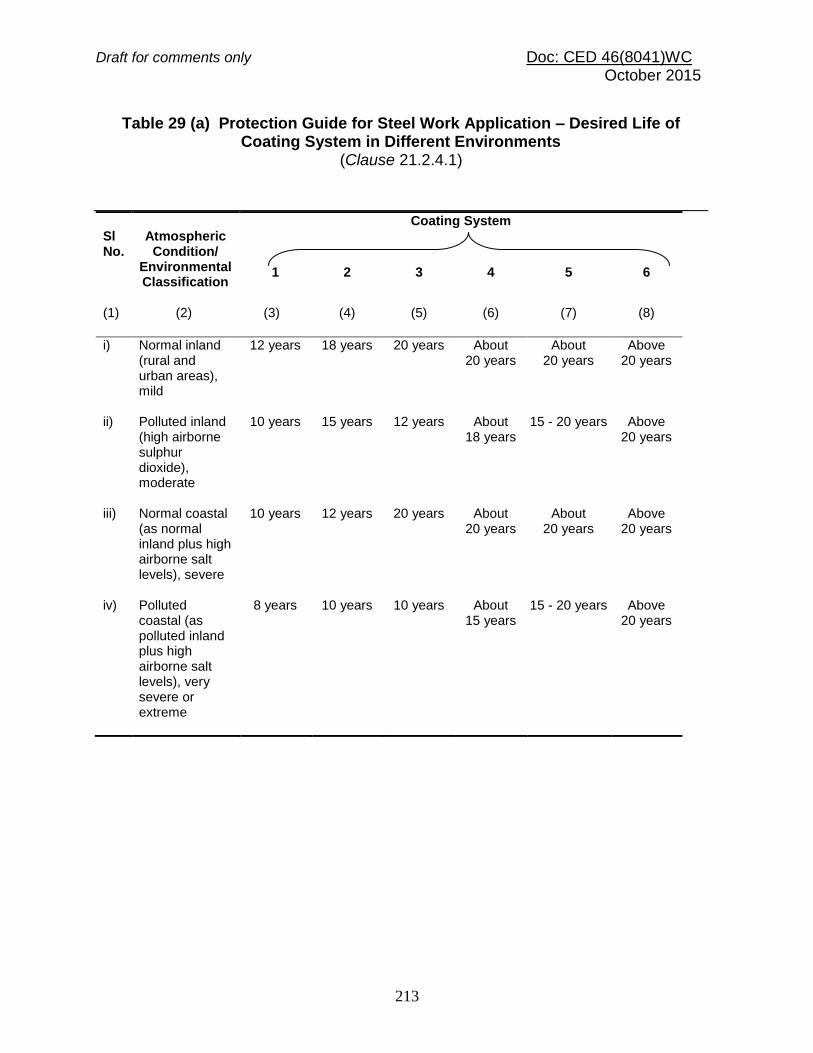
Draft for comments only Doc: CED 46(8041)WC October 2015
213
Table 29 (a) Protection Guide for Steel Work Application – Desired Life of Coating System in Different Environments
(Clause 21.2.4.1)
Sl No.
Atmospheric
Condition/ Environmental Classification
Coating System
1
2
3
4
5
6
(1) (2) (3) (4) (5) (6) (7) (8)
i) Normal inland (rural and urban areas), mild
12 years 18 years 20 years About 20 years
About 20 years
Above 20 years
ii) Polluted inland (high airborne sulphur dioxide), moderate
10 years 15 years 12 years About 18 years
15 - 20 years Above 20 years
iii) Normal coastal (as normal inland plus high airborne salt levels), severe
10 years 12 years 20 years About 20 years
About 20 years
Above 20 years
iv) Polluted coastal (as polluted inland plus high airborne salt levels), very severe or extreme
8 years 10 years 10 years About 15 years
15 - 20 years Above 20 years

Draft for comments only Doc: CED 46(8041)WC October 2015
214
Table 29 (b) (i) Protection Guide for Steel Work Application ― Specification for Different Coating System (Shop Applied Treatments)
(Clause 21.2.4.1)
Sl No.
Protection
Coating System
1 2 3 4 5 6
(1) (2) (3) (4) (5) (6) (7) (8)
i) Surface Preparation
Blast clean Blast clean Blast clean Blast clean Girt blast Blast clean
ii) Pre-fabrication primer
Zinc phosphate epoxy, 20
m
2 pack zinc-rich epoxy, 20
m
2 pack zinc-rich epoxy, 20
m
Ethyl zinc silicate, 20
m
iii) Post fabrication primer
High-build zinc phosphate modified alkyd, 60
m
2 pack zinc-rich epoxy, 20
m
Hot dip galvanized,
85 m
2 pack zinc-rich epoxy, 25
m
Sprayed zinc or sprayed aluminium
Ethyl zinc silicate, 60
m
iv) Intermediate coat
High-build zinc phosphate,
25 m
2 pack epoxy micaceous iron oxide
Sealer Chlorinated rubber alkyd, 35
m
v) Top coat
2 pack epoxy micaceous iron oxide,
85 m
Sealer
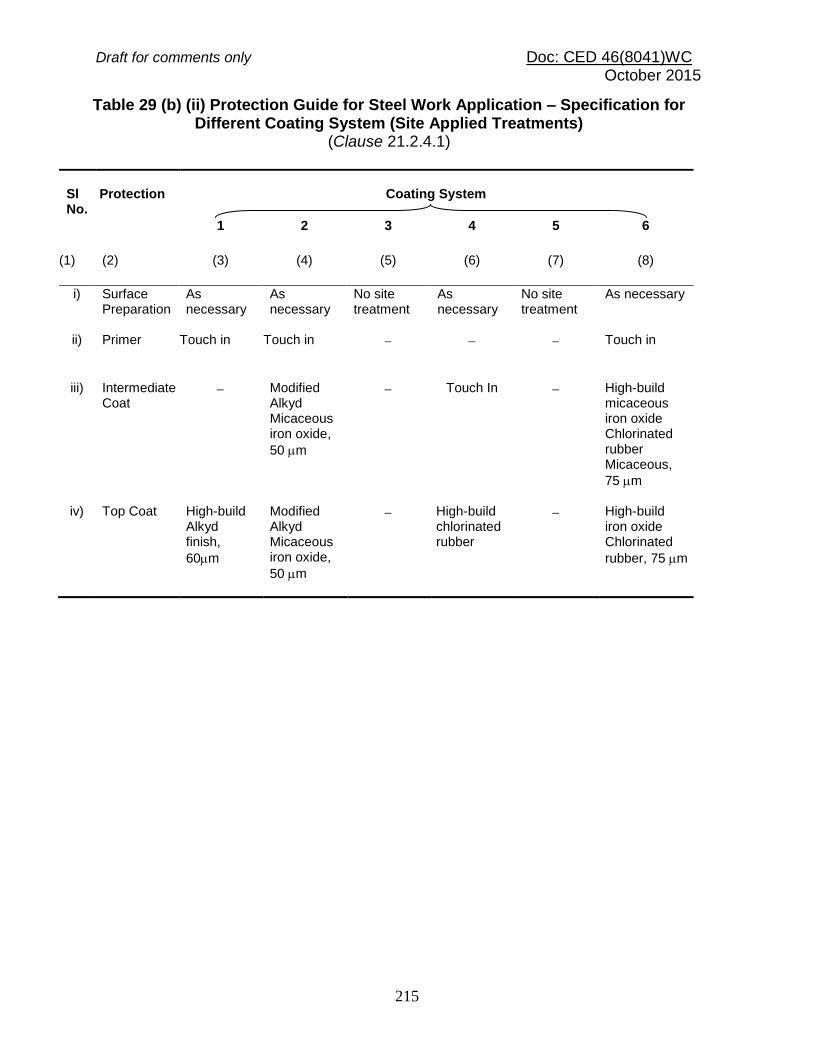
Draft for comments only Doc: CED 46(8041)WC October 2015
215
Table 29 (b) (ii) Protection Guide for Steel Work Application – Specification for Different Coating System (Site Applied Treatments)
(Clause 21.2.4.1)
Sl No.
Protection
Coating System
1 2 3 4 5 6
(1) (2) (3) (4) (5) (6) (7) (8)
i) Surface Preparation
As necessary
As necessary
No site treatment
As necessary
No site treatment
As necessary
ii) Primer Touch in Touch in Touch in
iii) Intermediate Coat
Modified Alkyd Micaceous iron oxide,
50 m
Touch In High-build micaceous iron oxide Chlorinated rubber Micaceous,
75 m
iv) Top Coat High-build Alkyd finish,
60m
Modified Alkyd Micaceous iron oxide,
50 m
High-build chlorinated rubber
High-build iron oxide Chlorinated
rubber, 75 m

Draft for comments only Doc: CED 46(8041)WC October 2015
216
SECTION 6 (p) FIRE RESISTANCE
22 FIRE RESISTANCE 22.1 Requirements The requirements shall apply to steel building elements designed to exhibit a required fire-resistance level (FRL) as per the relevant specifications. The provisions of this section are quite rudimentary and simplistic. Specialist literature for design of steel structures for fire resistance and design based on testing may be necessary for a more comprehensive design of steel buildings to resist fire. 22.1.1 For protected steel members and connections, the thickness of protection material (hi) shall be greater than or equal to that required to give a period of structural adequacy (PSA) greater than or equal to the required FRL. 22.1.2 For unprotected steel members and connections, the exposed surface area to mass ratio (ksm) shall be less than or equal to that required to give a PSA equal to the required FRL. 22.2 Fire Resistance Level The required FRL shall be as prescribed in Part 4 'Fire and Life Safety' as appropriate or in building specifications or as required by the user or the city ordinance. The FRL specified in terms of the duration (in min) of standard fire load without collapse depends upon:
a) the purpose for which structure is used, and b) the time taken to evacuate in case of fire.
22.3 Period of Structural Adequacy (PSA) 22.3.1 The calculation of PSA involves:
a) calculation of the strength of the element as a function of temperature of the element and the determination of limiting temperature;
b) calculation of the thermal response of the element, that is calculation of the variation of the temperature of the element or the parts of the element with time, when exposed to fire; and
c) determination of PSA at which the temperature of the element or parts of the element reaches the limiting temperature.

Draft for comments only Doc: CED 46(8041)WC October 2015
217
22.3.2 Determination of Period of Structural Adequacy The period of structural adequacy (PSA) shall be determined using one of the following methods:
a) By calculation:
1) determining the limiting temperature of the steel (Tl) in accordance with 22.5; and
2) determining the PSA as the time (t) (in min) from the start of the test to the time at which the limiting steel temperature is attained, in accordance with 22.6 for protected members and 22.7 for unprotected members.
b) By direct application of a single test in accordance with 22.8; or c) By calculation of the temperature of the steel member by using a rational method
of analysis confirmed by test data or by methods available in specialist literature.
22.4 Variation of Mechanical Properties of Steel with Temperature 22.4.1 Variation of Yield Stress with Temperature The influence of temperature on the yield stress of steel shall be taken as follows for structures of mild steels and high strength low alloy steels: where, fy(T) = yield stress of steel at T oC, fy(20) = yield stress of steel at 20 oC (room temperature), and T = Temperature of the steel, in oC. This relationship is shown by curve 1 in Fig. 24.
0.1
690
905
20y
y
T
f
Tf

Draft for comments only Doc: CED 46(8041)WC October 2015
218
FIG. 24 VARIATION OF MECHANICAL PROPERTIES OF STEEL WITH TEMPERATURE
For temperature less than 215 oC no reduction in the yield stress need to be considered. 22.4.2 Variation of Modulus of Elasticity with Temperature The influence of temperature on the modulus of elasticity shall be taken as follows for structures of mild steels and high strength low alloy steels:
1001ln0002
0.120 T
T
E
TE when 0 oC < T ≤ 600 oC
5.53
00011690
T
T
when CC 0001600 T
YIE
LD
ST
RE
SS
RA
TIO
OR
MO
DU
LU
S O
F E
LA
ST
ICIT
Y R
AT
IO
0
0 .2
0 .4
0 .6
0 .8
1
1 .2
0 2 0 0 4 0 0 6 0 0 8 0 0 1 0 0 0 1 2 0 0
Curve 1: Yield Stress Ratio
Curve 2: Modulus of Elasticity Ratio
2
1
STEEL TEMPERATURE (T)C
215

Draft for comments only Doc: CED 46(8041)WC October 2015
219
E (T) = Modulus of elasticity of steel at T oC, and E (20) = Modulus of elasticity of steel at 20 oC (room temperature). This relationship is shown by curve 2 in Fig. 24. 22.4.3 For special steel with higher temperature resistance, such as TMCP steels, the manufacturer’s recommendation shall be used to obtain the variation of yield strength and modulus of elasticity of steel with temperature. 22.5 Limiting Steel Temperature The limiting steel temperature (Tl) in degree Celsius in the case of ordinary steels, shall be calculated as follows:
Tl = 905 - 690rf
where rf = ratio of the design action on the member under fire to the design
capacity of the member (Rd = Ru/m) at room temperature, Rd, Ru = design strength and ultimate strength of the member at room temperature respectively, and
m = partial safety factor for strength. The design action under fire shall consider the following:
a) Reduced bond likely under fire, and b) Effects of restraint to expansion of the elements during fire.
Limiting steel temperature for special steels may be appropriately calculated using the thermal characteristics of the material obtained from the supplier of the steel.

Draft for comments only Doc: CED 46(8041)WC October 2015
220
22.6 Temperature Increase with Time in Protected Members 22.6.1 The time (t) at which the limiting temperature (Tl) is attained shall be determined by calculation on the basis of a suitable series of fire tests in accordance with 22.6.2 or from the results of a single test in accordance with 22.6.3. 22.6.1.1 For beams and for all members with a four-sided fire exposure condition, the limiting temperature (Tl) shall be taken as the average of all of the temperatures measured at the thermocouple locations on all sides. 22.6.1.2 For columns with a three-sided fire exposure condition, the limiting temperature (Tl) shall be taken as the average of the temperatures measured at the thermocouple locations on the face farthest from the wall. Alternatively, the temperatures from members with a four-sided fire exposure condition and having the same surface area to mass ratio may be used. 22.6.2 Temperature Based on Test Series Calculation of the variation of steel temperature with time shall be by interpolation of the results of a series of fire tests using the regression analysis equation specified in 22.6.2.1, subject to the limitations and conditions of 22.6.2.3. 22.6.2.1 Regression analysis The relationship between temperature (T) and time (t) for a series of tests on a group shall be calculated by least-square regression as follows:
sm
6
sm
i
i
sm
i
i
k
Tk
k
ThkThkTk
k
hkhkkt
543210
where t = time from the start of the test, in min; k0 to k6 = regression coefficients from test data (see 22.6.2.2); hi = thickness of fire protection material, in mm; T = Steel temperature, in degrees Celsius obtained from test as given in 22.6.1, T > 250 oC; and ksm = exposed surface area to mass ratio, in 103 mm2/kg. 22.6.2.2 In lieu of test results, the values for coefficients in Table 30 may be used in the equation 22.6.2.1 when the test satisfies the conditions specified in 22.6.2.3.
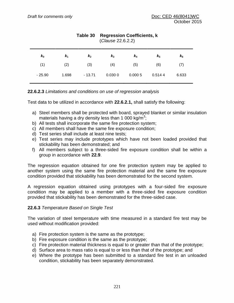
Draft for comments only Doc: CED 46(8041)WC October 2015
221
Table 30 Regression Coefficients, k
(Clause 22.6.2.2)
k0
k1
k2
k3
k4
k5
k6
(1) (2) (3) (4) (5) (6) (7)
- 25.90 1.698 - 13.71 0.030 0 0.000 5 0.514 4 6.633
22.6.2.3 Limitations and conditions on use of regression analysis Test data to be utilized in accordance with 22.6.2.1, shall satisfy the following:
a) Steel members shall be protected with board, sprayed blanket or similar insulation materials having a dry density less than 1 000 kg/m3;
b) All tests shall incorporate the same fire protection system; c) All members shall have the same fire exposure condition; d) Test series shall include at least nine tests; e) Test series may include prototypes which have not been loaded provided that
stickability has been demonstrated; and f) All members subject to a three-sided fire exposure condition shall be within a
group in accordance with 22.9. The regression equation obtained for one fire protection system may be applied to another system using the same fire protection material and the same fire exposure condition provided that stickability has been demonstrated for the second system. A regression equation obtained using prototypes with a four-sided fire exposure condition may be applied to a member with a three-sided fire exposure condition provided that stickability has been demonstrated for the three-sided case. 22.6.3 Temperature Based on Single Test The variation of steel temperature with time measured in a standard fire test may be used without modification provided:
a) Fire protection system is the same as the prototype; b) Fire exposure condition is the same as the prototype; c) Fire protection material thickness is equal to or greater than that of the prototype; d) Surface area to mass ratio is equal to or less than that of the prototype; and e) Where the prototype has been submitted to a standard fire test in an unloaded
condition, stickability has been separately demonstrated.

Draft for comments only Doc: CED 46(8041)WC October 2015
222
22.6.4 Parameters of Importance in the Standard Fire Test
a) Specimen type, loading, configuration, b) Exposed surface area to mass ratio, c) Insulation type, thermal properties and thickness, and d) Moisture content of the insulation material.
22.7 Temperature Increase with Time in Unprotected Members The time (t) at which the limiting temperature (Tl) is attained shall be calculated using the following equations:
a) Three-sided fire exposure condition
sm
l433.01022.02.5
k
TTt
b) Four-sided fire exposure condition
where t = time from the start of the test, in min;
T = steel temperature, in oC, 500 oC T 750 C, and ksm = exposed surface area to mass ratio,
2103 mm2/kg ksm 35 103 mm2/kg. For temperatures below 500 oC, linear interpolation shall be used, based on the time at 500 oC and an initial temperature of 20 oC at t equals 0. 22.8 Determination of PSA from a Single Test The period of structural adequacy (PSA) determined from a single test may be applied without modification provided:
a) Conditions, specified in 22.6.3 are satisfied, b) Conditions of support are the same as the prototype and the restraints are not less
favourable than those of the prototype, and c) Ratio of the design load for fire to the design capacity of the member is less than
or equal to that of the prototype.
sm
l
k
T T t
213
3
. 0 0263 . 0 7 . 4

Draft for comments only Doc: CED 46(8041)WC October 2015
223
(b) BLOCKING OF RIB VOIDS
FIG. 25 THREE SIDED FIRE EXPOSURE CONDITION REQUIREMENTS 22.9 Three-sided Fire Exposure condition Members subject to a three-sided fire exposure condition shall be considered in separate groups unless the following conditions are satisfied:
a) The characteristics of the members of a group as given below, shall not vary from one another by more than
(i) Concrete density:
groupinlowest
groupinhighest 1.25, and
(ii) Effective thickness (he):
groupinsmallest
groupinlargest 1.25
he
he
(a) EFFECTIVE THICKNESS
Concrete slab
Side view
Void blocked
with fire
protection
Material
Fire protection material Cross section
Steel
beam
Concrete slab Rib
void

Draft for comments only Doc: CED 46(8041)WC October 2015
224
where the effective thickness (he) is equal to the cross-sectional area excluding voids per unit width, as shown in Fig. 25 (a).
b) Rib voids shall either be:
(i) all open; or (ii) all blocked as shown in Fig. 25 (b).
c) Concrete slabs may incorporate permanent steel deck formwork.
22.10 Special Considerations 22.10.1 Connections Connections shall be protected with the maximum thickness of fire protection material required for any of the members framing into the connection to achieve their respective fire-resistance levels. This thickness shall be maintained over all connection components, including bolt heads, welds and splice plates. 22.10.2 Web Penetrations The thickness of fire protection material at and adjacent to web penetrations shall be the greatest of that required, when:
a) area above the penetration is considered as a three-sided fire exposure condition (ksm1) (see Fig 26),
b) area below the penetration is considered as a four-sided fire exposure condition (ksm2) (see Fig 26),and
c) section as a whole is considered as a three-sided fire exposure condition (ksm) (see Fig 26).
This thickness shall be applied over the full beam depth and shall extend on each side of the penetration for a distance at least equal to the beam depth and not less than 300 mm. 22.11 Fire Resistance Rating The fire resistance rating of various building components such as walls, columns, beams, and floors are given in Table 31 and Table 32. Fire damage assessment of various structural elements of the building and adequacy of the structural repairs can be done by the fire resistance rating for encased steel column and beam (Table 31 and Table 32).

Draft for comments only Doc: CED 46(8041)WC October 2015
225
FIG. 26 WEB PENETRATION
ksm2
ksm1
Section A-A Section B-B ksm
B
B
Side View of Beam With Web Penetration
A

Draft for comments only Doc: CED 46(8041)WC October 2015
226
Table 31 Encased Steel Columns, 203 mm X 203 mm (Protection Applied on Four Sides)
(Clause 22.11)
Sl
No.
(1)
Nature of Construction and Materials
(2)
Minimum Dimensions Excluding Any
Finish, for a Fire Resistance of mm
1 h (3)
1 ½ h
(4) 2 h (5)
3 h (6)
4 h (7)
i) Hollow protection (without an air cavity over the flanges):
a) Metal lathing with trowelled lightweight aggregate gypsum plaster
1)
13
15
20
32
–-
b) Plasterboard with 1.6 mm wire binding at 100 mm pitch, finished with lightweight
aggregate gypsum plaster less than the thickness specified:
1) 9.5 mm plaster board 2) 19 mm plaster board
10 10
15 13
–- 20
–- –-
–- –-
c) Asbestos insulating boards, thickness of board:
1) Single thickness of board, with 6 mm cover fillets at transverse joints 2) Two layers, of total thickness
–-
–-
19
–-
25
–-
--
38
--
50
d) Solid bricks of clay, composition or sand lime, reinforced in every horizontal joint, unplastered
50 50 50 75 100
e) Aerated concrete blocks
60 60 60 –- –-
f) Solid blocks of lightweight concrete hollow protection (with an air cavity over the flanges)
50 50 50 60 75
ii) Asbestos insulating board screwed to 25 mm asbestos battens
12 19 –- –- –-
iii) Solid protections
a) Concrete, not leaner than 1:2:4 mix (unplastered):
1) Concrete not assumed to be load bearing, reinforced
2)
2) Concrete assumed to be load bearing
25
50
25
50
25
50
50
75
75
75
b) Lightweight concrete, not leaner than 1:2: 4 mix (unplastered) concrete not assumed to be load bearing, reinforced
2)
25 25 25 25 25

Draft for comments only Doc: CED 46(8041)WC October 2015
227
1)
So fixed or designed, as to allow full penetration for mechanical bond. 2)
Reinforcement shall consist of steel binding wire not less than 2.3 mm diameter, or a steel mesh
weighing not less than 0.5 kg/m2. In concrete protection, the spacing of that reinforcement shall not
exceed 200 mm in any direction.
Table 32 Encased Steel Beams, 406 mm X 176 mm (Protection Applied on Three Sides)
(Clause 22.11)
Sl No. (1)
Nature of Construction and Materials
(2)
Minimum Thickness of Protection for a Fire Resistance of
mm
½ h (3)
1 h (4)
1½ h (5)
2 h (6)
3 h (7)
4 h (8)
i) Hollow protection (without an air cavity beneath the lower flanges):
a) Metal lathing with trowelled lightweight aggregate gypsum plaster
1)
13
13
15
20
25
–-
b) Plasterboard with 1.6 mm wire binding at 100 mm pitch, finished with lightweight aggregate gypsum plaster less than the thickness specified
2):
1) 9.5 mm plaster board 2) 19 mm plaster board
10 10
10 10
15 13
–- 20
–- –-
–- –-
c) Asbestos insulating boards, thickness of board: 1) Single thickness of board, with 6 mm cover fillets at transverse joints
2) Two layers, of total thickness
–-
–-
–-
–-
19
–-
25
–-
–-
38
–-
50
ii) Hollow protection (with an air cavity below the lower flange):
a) Asbestos insulating board screwed to 25 mm asbestos battens
9
12
–-
–-
–-
–-
iii) Solid protections
a) Concrete, not leaner than 1:2:4 mix (unplastered):
1) Concrete not assumed to be load bearing, reinforced
3)
2) Concrete assumed to be load bearing
25
50
25
50
25
50
25
50
50
75
75
75

Draft for comments only Doc: CED 46(8041)WC October 2015
228
b) Lightweight concrete, not leaner than 1:2:4 mix (unplastered)
4)
25 25 25 25 40 60
1) So fixed or designed, as to allow full penetration for mechanical bond.
2) Where wire binding cannot be used, expert advice should be sought regarding alternative methods of support to enable the lower edges of the plasterboard to be fixed together and to the lower flange, and for the top edge of the plasterboard to be held in position.
3) Reinforcement shall consist of steel binding wire not less than 2.3 mm in diameter, or a steel mesh weighing not less than 0.5 kg/m
2. In concrete protection, the spacing of that reinforcement shall not
exceed 200 mm in any direction. 4)
Concrete not assumed to be load bearing, reinforced.
SECTION 6 (q) FABRICATION AND ERECTION 23 FABRICATION AND ERECTION 23.1 General Tolerances for fabrication of steel structures shall conform to the accepted standard [6-6(42)]. Tolerances for erection of steel structures shall conform to the accepted standard [6-6(43)]. For general guidance on fabrication by welding, reference may be made to good practice [6-6(44)]. 23.2 Fabrication Procedures 23.2.1 Straightening Material shall be straightened or formed to the specified configuration by methods that will not reduce the properties of the material below the values used in design. Local application of pressure at room or at elevated temperature or other thermal means may be used for straightening, provided the above is satisfied. 23.2.2 Clearances The erection clearance for cleated ends of members, connecting steel to steel should preferably be not greater than 2.0 mm at each end. The erection clearance at ends of beams without web cleats should be not more than 3 mm at each end. Where for practical reasons, greater clearance is necessary, suitably designed seating should be provided. 23.2.2.1 The holes for bolts may be made as given in Table 19 of 16.2.1, unless otherwise specified by the engineer. The hole diameter in base plates shall not exceed the anchor bolt diameter by more than 6 mm.
Draft for comments only Doc: CED 46(8041)WC October 2015
229
23.2.2.2 In friction type of connection clearance may be maintained, unless specified otherwise in the design document. 23.2.3 Cutting Cutting shall be effected by sawing, shearing, cropping, machining or thermal cutting process. Shearing, cropping and gas cutting shall be clean, reasonably square, and free from any distortion. Should the inspector find it necessary, the edges shall be ground after cutting. Planning or finishing of sheared or gas-cut edges of plates or shapes shall not be required, unless specially noted on drawing or included in stipulated edge preparation for welding or when specifically required in the following section. Re-entrant corners shall be free from notches and shall have largest practical radii with a minimum radius of 15 mm. 23.2.3.1 Shearing Shearing of items over 16 mm thick to be galvanized and subject to tensile force or bending moment shall not be carried out, unless the item is stress relieved subsequently. The use of sheared edges in the tension area shall be avoided in location subject to plastic hinge rotation at factored loading. 23.2.3.2 Thermal Cutting Gas cutting of high tensile steel by mechanically controlled torch may be permitted, provided special care is taken to leave sufficient metal to be removed by machining, so that all metal that has been hardened by flame is removed. Hand flame cutting may be permitted only subject to the approval of the inspecting authority. Except where the material is subsequently joined by welding, no load shall be transmitted through a gas cut surface. Thermally cut free edges, which shall be subject to calculated static tensile stress shall be free from round bottom gouges greater than 5 mm deep. Gouges greater than 5 mm deep and notches shall be removed by grinding. 23.2.4 Holing 23.2.4.1 Holes through more than one thickness of material for members, such as compound stanchion and girder flanges, shall be where possible, drilled after the members are assembled and tightly clamped or bolted together. A round hole for a bolt shall either be machine flame cut, or drilled full size, or sub-punched 3 mm undersize and reamed to size or punched full size.
Draft for comments only Doc: CED 46(8041)WC October 2015
230
Hand flame cutting of a bolt hole shall not be permitted except as a site rectification measure for holes in column base plates. 23.2.4.2 Punching A punched hole shall be permitted only in material whose yield stress (fy) does not exceed 360 MPa and where thickness does not exceed (5 600/fy) mm. In cyclically loaded details, punching shall be avoided in plates with thickness greater than 12 mm. For greater thickness and cyclically loaded details, holes shall be either drilled from the solid or sub-punched or sub drilled and reamed. The die for all sub-punched holes or the drill for all sub-drilled holes shall be at least 3 mm smaller than the required diameter of finished hole. 23.2.4.3 Oversize holes A special plate washer of minimum thickness 4 mm shall be used under the nut, if the hole diameter is larger than the bolt diameter by 3 mm or more. Oversize hole shall not exceed 1.25d or (d+8) mm in diameter, were d is the nominal bolt diameter, in mm. A short slotted hole shall not exceed the appropriate hole size in width and 1.33d, in length. A long slotted hole shall not exceed the appropriate hole size in width and 2.5d, in length. If the slot length is larger than those specified, shear transfer in the direction of slot is not admissible even in friction type of connection. Slotted holes shall be punched either in one operation or else formed by punching or drilling two round holes apart and completed by high quality mechanically controlled flame cutting and dressing to ensure that bolt can freely travel the full length of the slot. 23.2.4.4 Fitted bolt holes Holes for turned and fitted bolts shall be drilled to a diameter equal to the nominal diameter of the shank or barrel subject to tolerance specified in the accepted standards [6-6(45)]. Preferably, parts to be connected with close tolerance or barrel bolts shall be firmly held together by tacking bolts or clamps and the holes drilled through all the thicknesses at one operation and subsequently reamed to size. All holes not drilled through all thicknesses at one operation shall be drilled to a smaller size and reamed out after assembly. Where this is not practicable, the parts shall be drilled and reamed separately through hard bushed steel jigs. 23.2.4.5 Holes for rivets or bolts shall not be formed generally by gas cutting process. However, advanced gas cutting processes such as plasma cutting may be used to make holes in statically loaded members only. In cyclically loaded members subjected

Draft for comments only Doc: CED 46(8041)WC October 2015
231
to tensile stresses which are vulnerable under fatigue, gas cutting shall not be used unless subsequent reaming is done to remove the material in the heat affected zone around the hole. 23.3 Assembly All parts of bolted members shall be pinned or bolted and rigidly held together during assembly. The component parts shall be assembled and aligned in such a manner that they are neither twisted nor otherwise damaged, and shall be so prepared that the specified camber, if any, is provided. 23.3.1 Holes in Assembly When holes are drilled in one operation through two or more separable parts, these parts, when so specified by the engineer, shall be separated after drilling and the burrs removed. Matching holes for rivets and black bolts shall register with each other so that a gauge of 1.5 mm or 2.0 mm (as the case may be, depending on whether the diameter of the rivet or bolt is less than or more than 25 mm) less in diameter than the diameter of the hole will pass freely through the assembled members in the direction at right angle to such members. Drilling done during assembly to align holes shall not distort the metal or enlarge the holes. Holes in adjacent part shall match sufficiently well to permit easy entry of bolts. If necessary, holes except oversize or slotted holes may be enlarged to admit bolts, by moderate amount of reaming. 23.3.2 Thread Length When design is based on bolts with unthreaded shanks in the shear plane, appropriate measures shall be specified to ensure that, after allowing for tolerance, neither the threads nor the thread run-out be in the shear plane. The length of bolt shall be such that at least one clear thread shows above the nut and at least one thread plus the thread run out is clear beneath the nut after tightening. One washer shall be provided under the rotated part.
Draft for comments only Doc: CED 46(8041)WC October 2015
232
23.3.3 Assembly Subjected to Vibration When non-preloaded bolts are used in a structure subject to vibration, the nuts shall be secured by locking devices or other mechanical means. The nuts of preloaded bolts may be assumed to be sufficiently secured by the normal tightening procedure. 23.3.4 Washers Washers are not normally required on non-preloaded bolts, unless specified otherwise. Tapered washers shall be used where the surface is inclined at more than 3º to a plane perpendicular to the bolt axis. Hardened washer shall be used for preloaded bolts or the nut, whichever is to be rotated. All material within the grip of the bolt shall be steel and no compressible material shall be permitted in the grip. 23.4 Riveting 23.4.1 Rivets shall be heated uniformly throughout their length, without burning or excessive scaling, and shall be of sufficient length to provide a head of standard dimensions. These shall, when driven, completely fill the holes and, if countersunk, the countersinking shall be fully filled by the rivet. If required, any protrusion of the countersunk head shall be dressed off flush. 23.4.2 Riveted member shall have all parts firmly drawn and held together before and during riveting, and special care shall be taken in this respect for all single-riveted connections. For multiple riveted connections, a service bolt shall be provided in every third or fourth hole. 23.4.3 Wherever practicable, machine riveting shall be carried out by using machines of the steady pressure type. 23.4.4 All loose, burned or otherwise defective rivets shall be cut out and replaced before the structure is loaded, and special care shall be taken to inspect all single riveted connections. 23.4.5 Special care shall be taken in heating and driving long rivets. 23.5 Bolting 23.5.1 In all cases where the full bearing area of the bolt is to be developed, the bolt shall be provided with a washer of sufficient thickness under the nut to avoid any threaded portion of the bolt being within the thickness or the parts bolted together, unless accounted for in design.

Draft for comments only Doc: CED 46(8041)WC October 2015
233
23.5.2 Pre-tensioned bolts shall be subjected to initial tension (the proof stress) by an appropriate pre-calibrated method. 23.6 Welding 23.6.1 Welding shall be in accordance with good practices [6-6(46)], as appropriate. 23.6.2 For welding of any particular type of joint, welders shall give evidence acceptable to the purchaser of having satisfactorily completed appropriate tests as prescribed in good practices [6-6(47)], as relevant. 23.6.3 Assembly and welding shall be carried out in such a way to minimize distortion and residual stress and that the final dimensions are within appropriate tolerances. 23.7 Machining of Butts, Caps and Bases 23.7.1 Column splices and butt joints of struts and compression members, depending on contact for stress transmission, shall be accurately machined and close-butted over the whole section with a clearance not exceeding 0.2 mm locally, at any place. Sum of all such clearance shall not be more than 30 percent of the contact area for stress transmission. In column caps and bases, the ends of shafts together with the attached gussets, angles, channels, etc; after connecting together should be accurately machined so that clearance between the contact surfaces shall not exceed 2 mm locally, subject further to the condition that sum total of all such clearance shall not exceed 30 percent of the total contact area for stress transmission. Care should be taken that these gussets, connecting angles or channels are fixed with such accuracy that they are not reduced in thickness by machining by more than 2.0 mm. 23.7.2 Where sufficient gussets and rivets or welds are provided to transmit the entire loading [see Section 6(d)], the column ends need not be machined. 23.7.3 Slab Bases and Caps Slab bases and slab caps, except when cut from material with true surfaces, shall be accurately machined over the bearing surfaces and shall be in effective contact with the end of the stanchion, the bearing face which is to be grouted to fit tightly at both top and bottom, unless welds are provided to transmit the entire column face. 23.7.4 To facilitate grouting, sufficient gap shall be left between the base plates and top of pedestal and holes shall be provided where necessary in stanchion bases for the escape of air.

Draft for comments only Doc: CED 46(8041)WC October 2015
234
23.8 Painting 23.8.1 Painting shall be done in accordance with the good practice good practices [6-6(48)]. 23.8.2 All surfaces, which are to be painted, oiled or otherwise treated, shall be dry and thoroughly cleaned to remove all loose scale and loose rust. 23.8.3 Shop contact surfaces need not be painted unless specified. If so specified, they shall be brought together while the paint is still wet. 23.8.4 Surfaces not in contact, but inaccessible after shop assembly, shall receive the full specified protective treatment before assembly. This does not apply to the interior of sealed hollow sections. 23.8.5 Chequered plates shall be painted but the details of painting shall be specified by the purchaser. 23.8.6 In case of surfaces to be welded, the steel shall not be painted or metal coated within a suitable distance of any edge to be welded, if the paint specified or the metal coating is likely to be harmful to welders or impair the quality of the welds. 23.8.7 Welds and adjacent parent metal shall not be painted prior to de-slagging, inspection and approval. 23.8.8 Parts to be encased in concrete shall not be painted or oiled. 23.8.9 Contact surface in friction type connection shall not be painted in advance. 23.9 Marking Each piece of steel work shall be distinctly marked before dispatch, in accordance with a marking diagram and shall bear such other marks as will facilitate erection. 23.10 Shop Erection 23.10.1 The steel work shall be temporarily shop erected complete or as arranged with the inspection agency so that accuracy of fit may be checked before dispatch. The parts shall be shop assembled with sufficient numbers of parallel drifts to bring and keep the parts in place. 23.10.2 In the case of parts drilled or punched, through steel jigs with bushes resulting in all similar parts being interchangeable, the steelwork may be shop erected in such position as arranged with the inspection agency.

Draft for comments only Doc: CED 46(8041)WC October 2015
235
23.10.3 In case of shop fabrication using numerically controlled machine data generated by computer software (like CAD), the shop erection may be dispensed with at the discretion of the inspector. 23.11 Packing All projecting plates or bars and all ends of members at joints shall be stiffened, all straight bars and plates shall be bundled, all screwed ends and machined surfaces shall be suitably packed and all rivets, bolts, nuts, washers and small and loose parts shall be packed separately in cases, so as to prevent damage or distortion during transit. 23.12 Inspection and Testing 23.12.1 The inspecting authority shall have free access at all reasonable times to those parts of the manufacturer’s works which are concerned with the fabrication of the steelwork and shall be afforded all reasonable facilities for satisfying himself that the fabrication is being undertaken in accordance with the provisions of this section. 23.12.2 Unless specified otherwise, inspection shall be made at the place of manufacture prior to dispatch and shall be conducted so as not to interfere unnecessarily with the operation of the work. 23.12.3 The manufacturer shall guarantee compliance with the provisions of this standard, if required to do so by the purchaser. 23.12.4 Should any structure or part of a structure be found not to comply with any of the provisions of this section, it shall be liable to rejection. No structure or part of the structure, once rejected shall be resubmitted for test, except in cases where the purchaser or his authorized representative considers the defect as rectifiable. 23.12.5 Defects, which may appear during fabrication, shall be made good with the consent of and according to the procedure laid down by the inspecting authority. 23.12.6 All gauges and templates necessary to satisfy the inspection authority shall be supplied by the manufacturer. The inspecting authority may, at his discretion, check the test results obtained at the manufacturer’s works by independent testing at outside laboratory, and should the material so tested be found to be unsatisfactory, the cost of such tests shall be borne by the manufacturer, and if found satisfactory, the cost shall be borne by the purchaser. 23.13 Site Erection 23.13.1 Plant and Equipment The suitability and capacity of all plant and equipment used for erection shall be to the satisfaction of the engineer.

Draft for comments only Doc: CED 46(8041)WC October 2015
236
23.13.2 Storing and Handling All structural steel should be so stored and handled at the site that the members are not subjected to excessive stresses and damage by corrosion due to exposure to environment. 23.13.3 Setting Out The positioning and leveling of all steelwork, the plumbing of stanchions and the placing of every part of the structure with accuracy shall be in accordance with the approved drawings and to the satisfaction of the engineer in accordance with the deviation permitted below. 23.13.3.1 Erection Tolerances Unloaded steel structure, as erected, shall satisfy the criteria specified in Table 33 within the specified tolerance limits. Each criterion given in the table shall be considered as a separate requirement, to be satisfied independent of any other tolerance criteria. The erection tolerances specified in Table 33 apply to the following reference points:
a) For a column, the actual centre point of the column at each floor level and at the base, excluding any base-plate or cap-plate. The level of the base plate on pedestal shall be so as to avoid contact with soil and corrosive environment; and
b) For a beam, the actual centre point of the top surface at each end of the beam,
excluding any end-plate.

Draft for comments only Doc: CED 46(8041)WC October 2015
237
Table 33 Normal Tolerances after Erection (Clause 23.13.3.1)
Sl No.
Criterion
Permitted Deviation
(1) (2) (3)
i)
Deviation of distance between adjacent columns
5 mm
ii) Inclination of a column in a multi-storey building between adjacent floor levels
0.002hs
where, hs is the storey height
iii) Deviation of location of a column in a multi-storey building at any floor level from a vertical line through the intended location of the column base
0.003 5 hb/n0.5
where, hb is the total height from the base to the floor level concerned and n is the number of storeys from the base to the floor level concerned
iv) Inclination of a column in a single storey building, (not supporting a crane gantry) other than a portal frame
0.003 5hc
where, hc is the height of the column
v) Inclination of the column of a portal frame (not supporting a crane gantry)
Mean: 0.002hc
Individual: 0.010hc
where hc is the height of the column
The straightness tolerances specified in Table 34 have been assumed in the derivation of the design stress for the relevant type of member. Where the curvature exceeds these values, the effect of additional curvature on the design calculations shall be reviewed. A tension member shall not deviate from its correct position relative to the members to which it is connected by more than 3 mm along any setting axis.
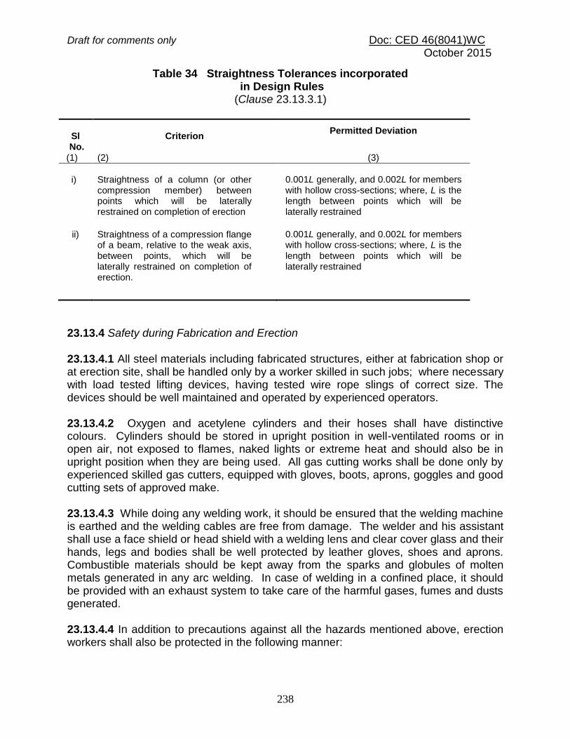
Draft for comments only Doc: CED 46(8041)WC October 2015
238
Table 34 Straightness Tolerances incorporated in Design Rules (Clause 23.13.3.1)
Sl No.
Criterion
Permitted Deviation
(1) (2) (3)
i)
Straightness of a column (or other compression member) between points which will be laterally restrained on completion of erection
0.001L generally, and 0.002L for members with hollow cross-sections; where, L is the length between points which will be laterally restrained
ii)
Straightness of a compression flange of a beam, relative to the weak axis, between points, which will be laterally restrained on completion of erection.
0.001L generally, and 0.002L for members with hollow cross-sections; where, L is the length between points which will be laterally restrained
23.13.4 Safety during Fabrication and Erection 23.13.4.1 All steel materials including fabricated structures, either at fabrication shop or at erection site, shall be handled only by a worker skilled in such jobs; where necessary with load tested lifting devices, having tested wire rope slings of correct size. The devices should be well maintained and operated by experienced operators. 23.13.4.2 Oxygen and acetylene cylinders and their hoses shall have distinctive colours. Cylinders should be stored in upright position in well-ventilated rooms or in open air, not exposed to flames, naked lights or extreme heat and should also be in upright position when they are being used. All gas cutting works shall be done only by experienced skilled gas cutters, equipped with gloves, boots, aprons, goggles and good cutting sets of approved make. 23.13.4.3 While doing any welding work, it should be ensured that the welding machine is earthed and the welding cables are free from damage. The welder and his assistant shall use a face shield or head shield with a welding lens and clear cover glass and their hands, legs and bodies shall be well protected by leather gloves, shoes and aprons. Combustible materials should be kept away from the sparks and globules of molten metals generated in any arc welding. In case of welding in a confined place, it should be provided with an exhaust system to take care of the harmful gases, fumes and dusts generated. 23.13.4.4 In addition to precautions against all the hazards mentioned above, erection workers shall also be protected in the following manner:

Draft for comments only Doc: CED 46(8041)WC October 2015
239
a) All workers shall wear helmets and shall also be provided with gloves and shoes. In addition those working at heights shall use safety belts.
b) All structures shall be so braced/guyed during erection that there is no possibility of
collapse before erection work is completed. c) Warning signs such as ‘Danger’, ‘Caution’, ‘440 volts’, ‘Do not smoke’, ‘Look ahead’,
etc; should be displayed at appropriate places. 23.13.4.5 For detailed safety precautions during erection, reference shall be made to the good practice [6-6(47)]. 23.13.5 Field Connections 23.13.5.1 Field riveting Rivets driven at the site shall be heated and driven with the same care as those driven in the shop. 23.13.5.2 Field bolting Field bolting shall be carried out with the same care as required for shop bolting. 23.13.5.3 Fillet welding Field assembly and welding shall be executed in accordance with the requirements for shop fabrications excepting such as manifestly apply to shop conditions only. Where the steel has been delivered painted, the paint shall be removed for a distance of at least 50 mm on either side of the joint. 23.14 Painting After Erection 23.14.1 Before painting of such steel which is delivered unpainted is commenced, all surfaces to be painted shall be dry and thoroughly cleaned from all loose scale and rust, as required by the surface protection specification. 23.14.2 The specified protective treatment shall be completed after erection. All rivet and bolt heads and the site welds after de-slagging shall be cleaned. Damaged or deteriorated paint surfaces shall first be made good with the same type of paint as the shop coat. Where specified, surfaces which will be in contact after site assembly, shall receive a coat of paint (in addition to any shop priming) and shall be brought together while the paint is still wet. No painting shall be used on contact surfaces in the friction connection, unless specified otherwise by the design document. 23.14.3 Where the steel has received a metal coating in the shop, this coating shall be completed on site so as to be continuous over any welds and site rivets or bolts, subject

Draft for comments only Doc: CED 46(8041)WC October 2015
240
to the approval of the engineer. Painting on site may complete protection. Bolts, which have been galvanized or similarly treated, are exempted from this requirement. 23.14.4 Surface, which will be inaccessible after site assembly, shall receive the full-specified protective treatment before assembly. 23.14.5 Site painting should not be done in frosty or foggy weather, or when humidity is such as to cause condensation on the surfaces to be painted. 23.15 Bedding Requirement 23.15.1 Bedding shall be carried out with Portland cement grout or mortar, as described under 23.15.4 or fine cement concrete in accordance with good practice [6-6(48)]. 23.15.2 For multi-storeyed buildings, this operation shall not be carried out until a sufficient number of bottom lengths of stanchions have been properly lined, leveled and plumbed and sufficient floor beams are in position. 23.15.3 Whatever method is employed, the operation shall not be carried out until the steelwork has been finally leveled and plumbed, stanchion bases being supported meanwhile by steel wedges or nuts; and immediately before grouting, the space under the steel shall be thoroughly cleaned. 23.15.4 Bedding of structure shall be carried out with grout or mortar, which shall be of adequate strength and shall completely fill the space to be grouted and shall either be placed under pressure or by ramming against fixed supports. The grouts or mortar used shall be non-shrinking variety. 23.16 Steel-Work Tenders and Contracts A few recommendations are given in Annex F for general information.
Draft for comments only Doc: CED 46(8041)WC October 2015
241
ANNEX A [Clause 10.1.1(c)]
ANALYSIS AND DESIGN METHODS
A-1 ADVANCED STRUCTURAL ANALYSIS AND DESIGN A-1.1 Analysis For a frame, comprising members of compact section with full lateral restraint, an advanced structural analysis may be carried out, provided the analysis can be shown to accurately model the actual behaviour of that class of frames. The analysis shall take into account the relevant material properties, residual stresses, geometrical imperfections, reduction in stiffness due to axial compression, second-order effects, section strength and ductility, erection procedures and interaction with the foundations. Advanced structural analysis for earthquake loads shall take into account, as appropriate the response history, torsional response, pounding against adjacent structures, and strain rate effects. A-1.2 Design For the strength limit state, it shall be sufficient to satisfy the section capacity requirements of Section 6(h) for the members subjected to bending, of Section 6(g) for axial members, of Section 6(i) for combined forces and of Section 6(j) for connections. Effect of moment magnification given in Section 6(i), instability given in Section 6(g) and lateral buckling given in Section 6(h) need not be considered while designing the member, since advanced analysis methods directly consider these. An advanced structural analysis for earthquake loads shall recognize that the design basis earthquake loads calculated in accordance with Section 1 of Part 6 is assumed to correspond to the load at which the first significant plastic hinge forms in the structure. A-2 SECOND ORDER ELASTIC ANALYSIS AND DESIGN A-2.1 Analysis In a second-order elastic analysis, the members shall be assumed to remain elastic, and changes in frame geometry under the design load and changes in the effective stiffness of the members due to axial forces shall be accounted for. In a frame where
the elastic buckling load factor (cr) of the frame as determined in accordance with 10.6 is greater than 5, the changes in the effective stiffness of the members due to axial forces may be neglected.
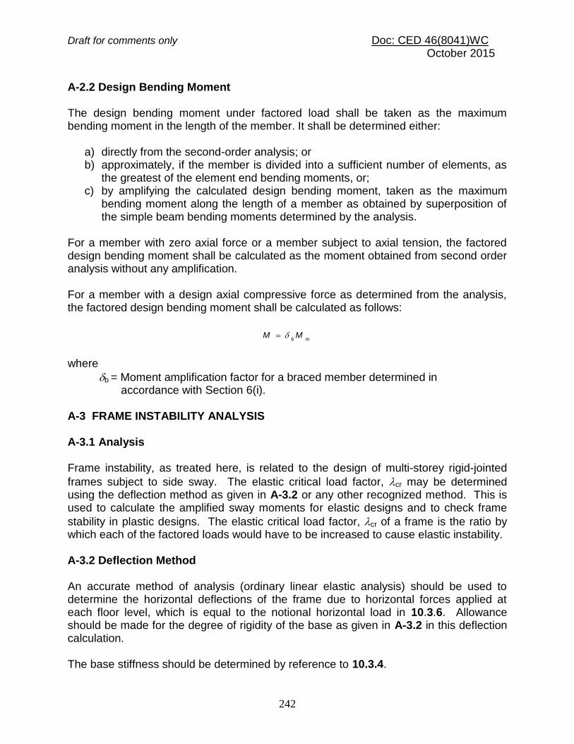
Draft for comments only Doc: CED 46(8041)WC October 2015
242
A-2.2 Design Bending Moment The design bending moment under factored load shall be taken as the maximum bending moment in the length of the member. It shall be determined either:
a) directly from the second-order analysis; or b) approximately, if the member is divided into a sufficient number of elements, as
the greatest of the element end bending moments, or; c) by amplifying the calculated design bending moment, taken as the maximum
bending moment along the length of a member as obtained by superposition of the simple beam bending moments determined by the analysis.
For a member with zero axial force or a member subject to axial tension, the factored design bending moment shall be calculated as the moment obtained from second order analysis without any amplification. For a member with a design axial compressive force as determined from the analysis, the factored design bending moment shall be calculated as follows:
mbMM
where
b = Moment amplification factor for a braced member determined in accordance with Section 6(i). A-3 FRAME INSTABILITY ANALYSIS A-3.1 Analysis Frame instability, as treated here, is related to the design of multi-storey rigid-jointed
frames subject to side sway. The elastic critical load factor, cr may be determined using the deflection method as given in A-3.2 or any other recognized method. This is used to calculate the amplified sway moments for elastic designs and to check frame
stability in plastic designs. The elastic critical load factor, cr of a frame is the ratio by which each of the factored loads would have to be increased to cause elastic instability. A-3.2 Deflection Method An accurate method of analysis (ordinary linear elastic analysis) should be used to determine the horizontal deflections of the frame due to horizontal forces applied at each floor level, which is equal to the notional horizontal load in 10.3.6. Allowance should be made for the degree of rigidity of the base as given in A-3.2 in this deflection calculation. The base stiffness should be determined by reference to 10.3.4.

Draft for comments only Doc: CED 46(8041)WC October 2015
243
The elastic critical load factor,cr
is calculated as:
Max s,
cr200
1
where
s, Max = largest value of the sway index where, s given by:
i
Liuisi
h
where hi = storey height;
ui= horizontal deflection of the top of the storey due to the combined gravity and notional loads; and
Li = horizontal deflection of the bottom of the storey due to gravity and notional load. A-3.3 Partial Sway Bracing In any storey the stiffening effect of infill wall panels may be allowed for by introducing a diagonal strut in that storey of area A, given by:
2/3
23/1
)/(bh
bhh
KkA
c
where h = storey height; b = width of the braced bay;
Kc = sum of the stiffness I/L, of the columns in that storey;
280
C
p
2
3
KE
Shk ; and
pS = Sum of spring stiffness (horizontal force per unit horizontal deflection
of all the panels in that storey determined from:
ppp
Et
bh
bhS
22
/1
/6.0
where tp = thickness of the wall panel, and Ep = modulus of elasticity of the panel material.
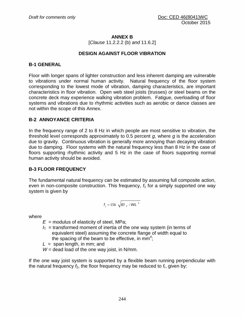
Draft for comments only Doc: CED 46(8041)WC October 2015
244
ANNEX B
[Clause 11.2.2.2 (b) and 11.6.2]
DESIGN AGAINST FLOOR VIBRATION
B-1 GENERAL Floor with longer spans of lighter construction and less inherent damping are vulnerable to vibrations under normal human activity. Natural frequency of the floor system corresponding to the lowest mode of vibration, damping characteristics, are important characteristics in floor vibration. Open web steel joists (trusses) or steel beams on the concrete deck may experience walking vibration problem. Fatigue, overloading of floor systems and vibrations due to rhythmic activities such as aerobic or dance classes are not within the scope of this Annex. B-2 ANNOYANCE CRITERIA In the frequency range of 2 to 8 Hz in which people are most sensitive to vibration, the threshold level corresponds approximately to 0.5 percent g, where g is the acceleration due to gravity. Continuous vibration is generally more annoying than decaying vibration due to damping. Floor systems with the natural frequency less than 8 Hz in the case of floors supporting rhythmic activity and 5 Hz in the case of floors supporting normal human activity should be avoided. B-3 FLOOR FREQUENCY The fundamental natural frequency can be estimated by assuming full composite action, even in non-composite construction. This frequency, f1 for a simply supported one way system is given by
4
1/156 WLEIf
T
where
E = modulus of elasticity of steel, MPa; IT = transformed moment of inertia of the one way system (in terms of equivalent steel) assuming the concrete flange of width equal to the spacing of the beam to be effective, in mm4; L = span length, in mm; and W = dead load of the one way joist, in N/mm.
If the one way joist system is supported by a flexible beam running perpendicular with the natural frequency f2, the floor frequency may be reduced to fr, given by:

Draft for comments only Doc: CED 46(8041)WC October 2015
245
2
2
2
1
2
111
fff
r
B-4 DAMPING The percentage of critical damping may be assumed approximately as given below: Sl No. (1)
System
(2)
Critical Damping Percent
(3)
i) Fully composite construction
2
ii) Bare steel beam and concrete deck
3 - 4
iii) Floor with finishes, false ceiling, fire proofing, ducts, furniture
6
iv) Partitions not located along a support or not spaced farther apart than 6 m and partitions oriented in orthogonal directions
Up to 12
B-5 ACCELERATION The peak acceleration ao, from heel impact for floors of spans greater than 7m and natural frequency f1, less than 10 Hz may be calculated as:
ao/g = 600 fr /W where
W = total weight of floors plus contents over the span length and equivalent floor width (b), in N; b = 40ts (20 ts when over hang is only on one side of the beam); ts = equivalent thickness of the slab, averaging concrete in slab and ribs; and g = acceleration due to gravity.

Draft for comments only Doc: CED 46(8041)WC October 2015
246
ANNEX C (Clause 13.2.2)
DETERMINATION OF EFFECTIVE LENGTH OF COLUMNS C-1 METHOD FOR DETERMINING EFFECTIVE LENGTH OF COLUMNS IN FRAMES In the absence of a more exact analysis, the effective length of columns in framed structures may be obtained by multiplying the actual length of the column between the centres of laterally supporting members (beams) given in Figs. 27 and 28 with the effective length factor K, calculated by using the equations given below, provided the connection between beam and column is rigid type: a) Non-sway frames (Braced frame) [(see 10.1.2 (a)] A frame is designated as non-sway frame if the relative displacement between the two adjacent floors is restrained by bracings or shear walls (see 10.1.2). The effective length factor, K, of column in non-sway frames is given by (see Fig. 27):
2121
2121
247036402
265014501
.)(.
.)(.
K
b) Sway frames (Moment Resisting Frames) [see 10.1.2 (b)] The effective length factor K, of column in sway frames is given by (see Fig. 28):
50
2121
2121
60801
120201.
..
..
K
where
1, 2 are given,
bcKK
K
Kc, Kb = Effective flexural stiffness of the columns and beams meeting
at the joint at the ends of the columns and rigidly connected at the joints, and these are calculated by:
K = C ( I / L ) I =moment of inertia of the member about an axis perpendicular to the plan of the frame, L = length of the member equal to centre to centre distance of the intersecting member, and
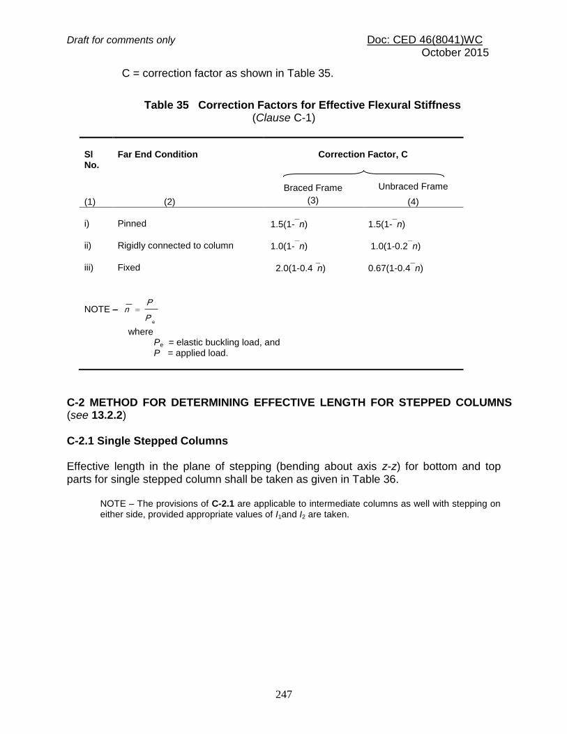
Draft for comments only Doc: CED 46(8041)WC October 2015
247
C = correction factor as shown in Table 35.
Table 35 Correction Factors for Effective Flexural Stiffness
(Clause C-1)
Sl No.
Far End Condition (2)
Correction Factor, C
(1)
Braced Frame (3)
Unbraced Frame
(4)
i)
Pinned
1.5(1-n)
1.5(1-n) ii)
Rigidly connected to column
1.0(1-n)
1.0(1-0.2n) iii)
Fixed
2.0(1-0.4n)
0.67(1-0.4n)
NOTE –
eP
Pn
where Pe = elastic buckling load, and P = applied load.
C-2 METHOD FOR DETERMINING EFFECTIVE LENGTH FOR STEPPED COLUMNS (see 13.2.2) C-2.1 Single Stepped Columns Effective length in the plane of stepping (bending about axis z-z) for bottom and top parts for single stepped column shall be taken as given in Table 36.
NOTE – The provisions of C-2.1 are applicable to intermediate columns as well with stepping on either side, provided appropriate values of I1and I2 are taken.
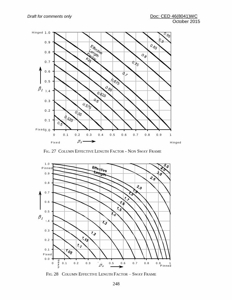
Draft for comments only Doc: CED 46(8041)WC October 2015
248
H in g e d
F ix e d
F ix e d H in g e d
0 . 0
0 . 1
0 . 2
0 . 3
0 . 4
0 . 5
0 . 6
0 . 7
0 . 8
0 . 9
1 . 0
0 0 .1 0 .2 0 .3 0 .4 0 .5 0 .6 0 .7 0 .8 0 .9 1
FIG. 27 COLUMN EFFECTIVE LENGTH FACTOR - NON SWAY FRAME
P in n e d
P in n e dFixed
F ix e d
0 .0
0 .1
0 .2
0 .3
0 .4
0 .5
0 .6
0 .7
0 .8
0 .9
1 .0
0 0 .1 0 .2 0 .3 0 .4 0 .5 0 .6 0 .7 0 .8 0 .9 1
FIG. 28 COLUMN EFFECTIVE LENGTH FACTOR – SWAY FRAME

Draft for comments only Doc: CED 46(8041)WC October 2015
249
Table 36 Effective Length of Singled Stepped Columns (Clause C-2.1)
Sl No.
Degree of End
Restraint
Sketch
Effective Length
Coefficients
Column
Parameters for all Cases
(1) (2) (3) (4)
i) Effectively held in position and restrained against rotation at both ends
12
11
2
12
1
KKK
3
1
1
2
C
KK
where K12 and K11 are to be taken as per Table 37
2
21
P
PP
2
1
1
2
1
I
I
L
LC
1
1
2
2
1
2
I
L
L
I
i
i
Effective length of bottom part of column in plane of stepping = K1L1
Effective length of top part of column in plane of stepping = K2L2
ii) Effectively held in position at both ends and restrained against rotation at bottom end only
12
11
2
12
1
KKK
3
1
1
2
C
KK
where K12 and K11 are to be taken as per Table 38
iii) Effectively held in position and restrained against rotation at bottom end, and top end held against rotation but not held in position
K1 to be taken as per Table 39
3
1
1
2
C
KK
iv) Effectively held in position and restrained against rotation at bottom end, and top end neither held against rotation nor held in position
K1 to be taken as per Table 40
3
1
1
2
C
KK
P2
P1 I2
I1
L2
L1

Draft for comments only Doc: CED 46(8041)WC October 2015
250
Table 37 Coefficients of Effective Lengths K12 and K11 for Columns with Both Ends Effectively Held in Position and Restrained Against Rotation
(Table 36)
Coefficients K12 and K11 for L2/L1 Equal to
P 2
P 1 I 1
I 1
L 1
L 1
P 1 + P 2
I2/I1
0.1 0.2 0.3 0.4 0.5 0.6 0.7 0.8 0.9 1.0 1.2 1.4 1.6 1.8 2.0
Coefficient K12 (P1 = 0)
0.05 0.74 0.94 1.38 1.60 1.87 2.07 2.23 2.39 2.52 2.67 3.03 3.44 3.85 4.34 4.77
0.1 0.67 0.76 1.00 1.20 1.42 1.61 1.78 1.92 2.04 2.20 2.40 2.60 2.86 3.18 3.41
0.2 0.64 0.70 0.79 0.93 1.07 1.23 1.41 1.50 1.60 1.72 1.92 2.11 2.28 2.45 2.64
0.3 0.62 0.68 0.74 0.85 0.95 1.06 1.18 1.28 1.39 1.48 1.67 1.82 1.96 2.12 2.20
0.4 0.60 0.66 0.71 0.77 0.82 0.93 0.99 1.08 1.17 1.23 1.39 1.53 1.66 1.79 1.92
0.5 0.59 0.65 0.70 0.77 0.82 0.93 0.99 1.08 1.17 1.23 1.39 1.53 1.66 1.79 1.92
1.0 0.55 0.60 0.65 0.70 0.75 0.80 0.85 0.90 0.95 1.00 1.10 1.20 1.30 1.40 1.50
Coefficient K11 (P2 = 0)
0.05 0.65 0.67 0.71 0.85 1.01 1.17 1.31 1.41 1.50 1.57 1.67 1.74 1.78 1.82 1.86
0.1 0.64 0.65 0.65 0.65 0.78 0.92 1.05 1.15 1.25 1.33 1.45 1.55 1.62 1.68 1.71
0.2 0.62 0.64 0.65 0.65 0.66 0.73 0.83 0.92 1.01 1.09 1.23 1.33 1.41 1.48 1.54
0.3 0.60 0.63 0.64 0.65 0.66 0.67 0.73 0.81 0.89 0.94 1.09 1.20 1.28 1.35 1.41
0.4 0.58 0.63 0.63 0.64 0.64 0.66 0.68 0.75 0.82 0.88 1.01 1.10 1.19 1.26 1.32
0.5 0.57 0.61 0.63 0.64 0.64 0.65 0.68 0.72 0.77 0.83 0.94 1.04 1.12 1.19 1.25
1.0 0.55 0.58 0.60 0.61 0.62 0.63 0.65 0.67 0.70 0.73 0.80 0.88 0.93 1.01 1.05
NOTE – Intermediate value may be obtained by interpolation
___________________________________________________________________________________________________

Draft for comments only Doc: CED 46(8041)WC October 2015
251
Table 38 Coefficients of Effective Lengths K12 And K11 for columns with both ends Effectively Held in Position and Restrained Against Rotation at Bottom End Only
(Table 36) ________________________________________________________________________________________________________
Coefficients K12 and K11 for L2/L1 Equal to
I2/I1
0.1 0.2 0.3 0.4 0.5 0.6 0.7 0.8 0.9 1.0 1.2 1.4 1.6 1.8 2.0
Coefficient K12 (P1 = 0)
0.05 0.97 1.66 2.10 2.43 2.72 2.92 3.08 3.24 3.48 3.73 4.22 4.85 5.36 6.00 6.58 0.1 0.83 1.21 1.57 1.95 2.14 2.33 2.46 2.60 2.76 2.91 3.28 3.61 4.03 4.43 4.85 0.3 0.78 0.90 1.09 1.27 1.44 1.60 1.74 1.86 1.98 2.11 2.35 2.51 2.76 2.99 3.25 0.5 0.78 0.86 0.99 1.10 1.22 1.35 1.47 1.57 1.67 1.76 1.96 2.15 2.34 2.50 2.76 1.0 0.78 0.85 0.92 0.99 1.06 1.13 1.20 1.27 1.34 1.41 1.54 1.68 1.82 1.97 2.10
Coefficient K11 (P2 = 0)
0.05 0.67 0.67 0.82 1.16 1.35 1.48 1.58 1.65 1.69 1.74 1.81 1.84 1.86 1.88 1.90 0.1 0.67 0.67 0.73 0.93 1.11 1.25 1.36 1.45 1.52 1.57 1.66 1.72 1.77 1.80 1.82 0.3 0.67 0.67 0.67 0.71 0.80 0.90 0.99 1.08 1.15 1.22 1.33 1.41 1.48 1.54 1.59 0.5 0.67 0.67 0.67 0.69 0.73 0.81 0.87 0.94 1.01 1.07 1.17 1.26 1.33 1.39 1.44 1.0 0.67 0.67 0.67 0.68 0.71 0.74 0.78 0.82 0.87 0.91 0.99 1.07 1.13 1.19 1.24
NOTE – Intermediate value may be obtained by interpolation.
________________________________________________________________________________________________________
P 2
P 1 I 2
I 1
L 2
L 1
P 1 + P 2
P

Draft for comments only Doc: CED 46(8041)WC October 2015
252
Table 39 Coefficients of Effective Lengths K1 for Columns Effectively Held in Position and Restrained Against Rotation at Bottom End and Top End Held Against Rotation but not Held in Position
(Table 36) __________________________________________________________________________________________________
C1
Coefficients K1 for I2 / I1 Equal to 0.1 0.2 0.3 0.4 0.5 0.6 0.7 0.8 0.9 1.0 1.2 1.4 1.6 1.8 2.0
0 2.0 1.8 1.7 1.67 1.6 1.55 1.50 1.4 1.43 1.4 1.37 1.3 1.1 1.10 1.0
0.5 2.0 1.9 1.8 1.74 1.6 1.65 1.61 1.5 1.55 1.5 --- --- --- ---- ---- 1.0 2.0 2.0 2.0 2.00 2.0 2.00 ---- ---- ---- ---- ---- ---- ---- ---- ---- 1.5 2.0 2.2 2.3 2.48 ---- ---- ---- ---- ---- ---- ---- ---- ---- ---- ---- 2.0 2.0 2.6 2.9 ---- ---- ---- ---- ---- ---- ---- ---- ---- ---- ---- ---- 2.5 2.5 3.1 3.5 ---- ---- ---- ---- ---- ---- ---- ---- ---- ---- ---- ---- 3.0 3.0 3.7 4.1 ---- ---- ---- ---- --- ---- ---- ---- ---- ---- ---- ----
NOTE – Intermediate values may be obtained by interpolation.
Table 40 Coefficients of Effective Lengths K1 for Columns with Top Ends Free and Bottom
End Effectively Held in Position and Restrained Against Rotation (Table 36)
__________________________________________________________________________________________________
C1
Coefficients K1 for I2/I1 Equal to
0.1
0.2 0.4 0.6 0.8 1.0 1.2 1.4 1.6 1.8 2.0 2.5 5.0 10 20
0 2.0 2.0 2.0 2.0 2.0 2.0 2.0 2.0 2.0 2.0 2.0 2.0 2.0 2.0 2.0 0.5 2.0 2.14 2.24 2.36 2.47 2.57 2.67 2.76 2.85 2.94 3.02 --- --- --- ---- 1.0 2.0 2.73 3.13 3.44 3.74 4.00 ---- ---- ---- ---- ---- ---- ---- ---- ---- 1.5 3.0 3.77 4.35 4.86 ---- ---- ---- ---- ---- ---- ---- ---- ---- ---- ---- 2.0 4.0 4.90 5.67 ---- ---- ---- ---- ---- ---- ---- ---- ---- ---- ---- ---- 2.5 5.0 6.08 7.00 ---- ---- ---- ---- ---- ---- ---- ---- ---- ---- ---- ---- 3.0 6.0 7.25 ---- ---- ---- ---- ---- ---- ---- ---- ---- ---- ----- ---- ----
NOTE – Intermediate values may be obtained by interpolation.
__________________________________________________________________________________________________
P 2
P 1
I 2
I 1
L 2
L 1
P 1 + P 2
P 2
P 1 I 2
I 1
L 2
L 1
P 1 + P 2

Draft for comments only Doc: CED 46(8041)WC October 2015
253
C-3 Effective Length for Double Stepped Columns Effective lengths in the plane of steppings (bending about axis z-z) for bottom, middle and top parts for a double stepped column shall be taken as follows (see also Fig. 29): (a)
FIG. 29 EFFECTIVE LENGTH OF DOUBLE STEPPED COLUMNS Coefficient K1 for effective length of bottom part of double stepped column shall be taken from the formula: where
K1, K2, and K3 are taken from Table 41.
3
1
1
P
Pt ,
3
22
P
Pt ,
1
2
2
L
Ln
I’av = average value of moment of inertia for the lower and middle parts
= 21
2211
LL
LILI
I’av = average value of moment of inertia for the middle and top parts
= 32
3322
LL
LILI
21
12
2
2
3
2
22
2
11
1
1
'1
tt
I
InKKtKt
K
av
P3
P1
I1
I2
P2
I3
L3
L2
L1
y
y
z z (a)
L2+L3
L1
P
I1
I’’av
(b)
L3
L1 + L2
P
I3
I’av
(c)
L3
L1 + L2
P3
I3
I’av
(d)

Draft for comments only Doc: CED 46(8041)WC October 2015
254
Value of coefficient K2 for middle part of column is given by formula:
2
1
2
C
KK , and
Value of coefficient K3 for the top part of the column is given by:
3
3
1
3
C
KK
where
3212
321
1
2
2
PPPI
PPI
L
LC
,
3213
31
1
3
3
PPPI
PI
L
LC
NOTE – The provisions of C-3.1 are applicable to intermediate columns as well with steppings on either side, provided appropriate values of I1, I2 and I3 are taken.

Draft for comments only Doc: CED 46(8041)WC October 2015
255
Table 41 Values of K1, K2 and K3
(Clause C-3) ____________________________________________________________________________
Sl No.
(1)
Degree of End Restraint
(2)
Sketch
(3)
K1
(4)
K2
(5)
K3
(6)
Column Parameters for all
Cases (7)
i) Effectively held in position and restrained against rotation at both ends
K1 = K11
where K11 is taken from Table 37
K2 = K11
where K11 is taken from Table 37
K3 = K12
where K12 is taken from Table 37
ii) Effectively held in position at both ends and restrained against rotation at bottom end only
K1 = K11
where K11 is taken from Table 38
K2 = K11
where K11 is taken from Table 38
K3 = K12
where K12 is taken from Table 38
iii) Effectively held in position and restrained against rotation at bottom end, and top end held against rotation but not held in position
K1 = K1
where K1 is taken from Table 39 with C1=0
K2 = K1
where K1 is taken from Table 39 with C1=0
K3 = K1
where K1 is taken from Table 39 with
3
av
21
3
1I
I
LL
LC
iv) Effectively held in position and restrained against rotation at bottom end, and top end neither held against rotation nor against translation.
K1 = 2 K2 = 2
K3 = K1
where K1 is taken from Table 40 with
3
av
21
31
I
I
LL
LC
_____________________________________________________________________________
P1
I1
I2
P2 I3
P3
L3
L2
L1

Draft for comments only Doc: CED 46(8041)WC October 2015
256
ANNEX D
(Clause 14.2.2.1)
ELASTIC LATERAL TORSIONAL BUCKLING
D-1 ELASTIC CRITICAL MOMENT
D-1.1 General
The elastic critical moment is affected by:
a) Moment gradient in the unsupported length, b) Boundary conditions at the lateral support points, c) Non-symmetric and non-prismatic nature of the member, and d) Location of transverse load with respect to shear centre.
The boundary conditions at the lateral supports have two components:
a) Torsional restraint – where the cross section is prevented from rotation about the shear centre, and
b) Warping restraint – where the flanges are prevented from rotating in their own plane about an axis perpendicular to the flange.
The elastic critical moment corresponding to lateral torsional buckling of a doubly symmetric prismatic beam subjected to uniform moment in the unsupported length and torsionally restraining lateral supports is given by:
50
2
2
2
2.
y
LTt
y
w
LT
y
cr
)(
)(
IE
LIG
I
I
L
EIM
where
Iy, Iw, It = moment of inertia about the minor axis, warping constant and St.Venant’s torsion constant of the cross-section, respectively (see Annex G for properties of sections);
G = modulus of rigidity; and
LLT= effective length against lateral torsional buckling (see 14.3).
This equation in simplified form for I-section has been presented in 14.2.2.1.

Draft for comments only Doc: CED 46(8041)WC October 2015
257
While the simplified equation is generally on the safe side, there are many situations where this may be very conservative. More accurate calculation of the elastic critical moment for general case of unsymmetrical sections, loading away from shear centre and beams with moment gradient can be obtained from specialist literature, by using an appropriate computer program or equations given below.
D-1.2 Elastic Critical Moment of a Section Symmetrical About Minor Axis
In case of a beam which is symmetrical only about the minor axis, and bending about major axis, the elastic critical moment for lateral torsional buckling is given by the general equation,
j3gj3g2
y
LTt
y
w
wLT
y
crycycycyc
IE
LIG
I
I
K
K
L
EIcM
2
5.0
2
2
22
2
2
1
)(
)(
where
c1, c2, c3 = factors depending upon the loading and end restraint conditions (see Table 42);
K = effective length factors of the unsupported length accounting for boundary conditions at the end lateral supports. The effective length factor K varies from 0.5 for complete restraint against rotation about weak axis to 1.0 for free rotate about weak axis, with 0.7 for the case of one end fixed and other end free. It is analogous to the effective length factors for compression members with end rotational restraint;
Kw = warping restraint factor. Unless special provisions to restrain warping of the section at the end lateral supports are made, Kw should be taken as 1.0;
yg = y distance between the point of application of the load and the shear centre of the cross section and is positive when the load is acting towards the shear centre from the point of application;
yj = z
222
As 5.0 IydAyzy ;
ys =co-ordinate of the shear centre with respect to centroid, positive when the shear centre is on the compression side of the centroid; and
y, z = co-ordinates of the elemental area with respect to centroid of the section.

Draft for comments only Doc: CED 46(8041)WC October 2015
258
yj can be calculated by using the following approximation:
a) Plain flanges
yj = 0.8 ( 2f – 1) hy /2.0 (when f > 0.5)
yj = 1.0 ( 2f – 1) hy /2.0 (when f 0.5)
b) Lipped flanges
yj = 0.8 ( 2f – 1) (1+ hL/h) hy/2 (when f > 0.5)
yj = ( 2f – 1) (1+ hL/h) hy/2 (when f 0.5)
where
hL = height of the lip,
h = overall height of the section,
hy = distance between shear centre of the two flanges of the cross-section, and
f = Ifc /(Ifc + Ift) where Ifc, Ift are the moment of inertia of the compression and tension flanges, respectively, about the minor axis of the entire section.
It = St. Venant's Torsion constant, given by:
3/3
iittbI for open section
tbA //42
e for hollow section
where
Ae = area enclosed by the section, and
b, t = breadth and thickness of the elements of the section, respectively.
Iw = The warping constant, given by:
(1-f) f Iy hy2 for I-sections mono-symmetric about weak axis
= 0 for angle, Tee, narrow rectangle section and approximately for hollow sections

Draft for comments only Doc: CED 46(8041)WC October 2015
259
Table 42 Constants c1, c2, and c3
(Clause D-1.2)
Loading and Support Conditions
Bending Moment Diagram
Value of K
Constants
c1 c2 c3
(1) (2) (3) (4) (5) (6)
ψ = +1
1.0
0.7
0.5
1.000
1.000
1.000
---
1.000
1.113
1.144
ψ= + ¾
1.0
0.7
0.5
1.141
1.270
1.305
---
0.998
1.565
2.283
ψ = + ½ 1.0
0.7
0.5
1.323
1.473
1.514
---
0.992
1.556
2.271
ψ = + ¼
1.0
0.7
0.5
1.563
1.739
1.788
---
0.977
1.531
2.235
ψ = 0 1.0
0.7
0.5
1.879
2.092
2.150
---
0.939
1.473
2.150
ψ = - ¼ 1.0
0.7
0.5
2.281
2.538
2.609
---
0.855
1.340
1.957
ψM M
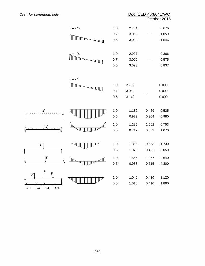
Draft for comments only Doc: CED 46(8041)WC October 2015
260
ψ = - ½ 1.0
0.7
0.5
2.704
3.009
3.093
---
0.676
1.059
1.546
ψ = - ¾ 1.0
0.7
0.5
2.927
3.009
3.093
---
0.366
0.575
0.837
ψ = - 1
1.0
0.7
0.5
2.752
3.063
3.149
---
0.000
0.000
0.000
1.0
0.5
1.132
0.972
0.459
0.304
0.525
0.980
1.0
0.5
1.285
0.712
1.562
0.652
0.753
1.070
1.0
0.5
1.365
1.070
0.553
0.432
1.730
3.050
1.0
0.5
1.565
0.938
1.267
0.715
2.640
4.800
1.0
0.5
1.046
1.010
0.430
0.410
1.120
1.890
W
W
F
F
L/4 L/4 L/4 L / 4
F F ℄

Draft for comments only Doc: CED 46(8041)WC October 2015
261
ANNEX E
(Clause 16.6.1)
CONNECTIONS
E-1 GENERAL The requirement for the design of splice and beam to column connection as well as recommendation for their design shall be as given below. E-2 BEAM SPLICES E-2.1 For rolled section beam splices located away from the point of maximum moment, it may be assumed that the flange splice carries all the moment and the web splice carries the shear (see Fig. 30). However in the case of a deep girder, the total moment may be divided between the flange and the web in accordance with the stress distribution. The web connection should then be designed to resist its share of moment and shear. Even web splice is designed to carry only shear force, the moment about the centroid of the bolt group on either side of the splice should be designed for moment due to eccentricity. E-2.2 Flange joints should preferably not be located at points of maximum stress. Where splice plates are used, their area shall not be less than 5 percent in excess of the area of the flange element spliced; and their centre of gravity shall coincide, as nearly as possible with that of the element spliced. There shall be enough fasteners on each side of the splice to develop the load in the element spliced plus 5 percent but in no case should the strength developed be less than 50 percent of the effective strength of the material spliced. Wherever possible in welded construction, flange plates shall be joined by complete penetration butt welds. These butt welds shall develop the full strength of the plates. Whenever the flange width or thickness changes at the splice location, gradual transition shall be made in the width/thickness of the larger flange. E-2.3 When beam splice is located at the point of inflection of a continuous beam, the flange splicing requirement given above may be relaxed appropriately.

Draft for comments only Doc: CED 46(8041)WC October 2015
262
(a) Conventional Splice (Typical) (b) End Plate
FIG. 30 BEAM SPLICES
E-3 COLUMN SPLICE E-3.1 Where the ends of compression members are faced for bearing over the whole area, they shall be spliced to hold the connected parts aligned. The ends of compression members faced for bearing shall invariably be machined to ensure perfect contact of surfaces in bearing (see Fig. 31). E-3.2 Where such members are not faced for complete bearing the splices shall be designed to transmit all the forces to which the members is subjected at the splice location. E-3.3 Wherever possible, splices shall be proportioned and arranged so that centroidal axis of the splice coincides as nearly as possible with the centroidal axes of the members joined, in order to avoid eccentricity; but where eccentricity is present in the joint, the resulting stress considering eccentricity shall be provided for. E-3.4 If a column flange is subjected to significant tension or if the faces are not prepared for bearing, or if full continuity is required without slip, only HSFG bolts shall be used.
Inner Splice Plates (optional)
V V M M
V V
M M
If required under design
Splice Plate (optional)

Draft for comments only Doc: CED 46(8041)WC October 2015
263
E-4 BEAM-TO-COLUMN CONNECTIONS E-4.1 Simple Connections Simple connections are assumed to transfer only shear at some nominal eccentricity and typically used in frames up to about five stories in height, where strength rather than stiffness govern the design. In such frames separate lateral load resisting system is to be provided in the form of bracings or shear walls. The connections shown in Fig. 32 (a), (b), (c) and (d) can be assumed as simple connections in framed analysis and need to be checked only for the transfer of shear from beam to column. E-4.2 Rigid Connections In high-rise and slender structures, stiffness requirements may warrant the use of rigid connections. Rigid connections transfer significant moments to the columns and are assumed to undergo negligible deformations at the joint. These are necessary in sway frames for stability and also contribute in resisting lateral loads. The connections shown in Fig. 32 (e), (f), (g) can be assumed as rigid connection in frame analysis and need to be checked for both shear and moment transfer from beam to the column. Fully welded connections can also be considered as rigid beam to column connections. E-4.3 Semi-rigid Connections Semi-rigid connections fall between the two types mentioned above. The fact is that simple connections do have some degree of rotational rigidity as in the semi-rigid connections. Similarly rigid connections do experience some degree of joint deformation and this can be utilized to reduce the joint design moments.
FIG. 31 COLUMN SPLICE (Typical)

Draft for comments only Doc: CED 46(8041)WC October 2015
264
The moment-rotation relationship of the connections have to be determined based on experiments conducted for the specific design or based on the relationship derived from tests, presented in specialist literature. The simplest method of analysis will be to idealize the connection as an equivalent rotational spring with either a bilinear or non-linear moment-rotation characteristics. The classification proposed by Bjorhovde combined with the Frye-Morris model can be used with convenience to model semi-rigid connections, as given in the next section.
E-4.3.1 Connection Classification Connections are classified according to their ultimate strength or in terms of their initial elastic stiffness and Bjorhovde’s classification. It is based on the non-dimensional
moment parameter (m1 = Mu / Mpb) and the non-dimensional rotation parameter ( 1 =
r / p), where p is the plastic rotation. The Bjorhovde’s classification is based on a reference length of the beam equal to 5 times the depth of the beam. The limits used for connection classification are shown in Table 43 and are graphically represented in Fig. 33. E-4.3.2 Connection Models Frye-Morris has derived the following polynomial model for the moment curvature relationship of semi-rigid connections.
r = C1(KM)1 + C2 (KM)3 + C3 (KM)5
where
M = moment at the joint, in kN.m; K = standardization parameter which depend on the connection type and geometry; and
C1, C2, C3 = curve fitting constants Table 44 shows the curve fitting constants and standardization constants for Frye-Morris Model [All size parameters in the table are in mm, (see Fig. 32)].
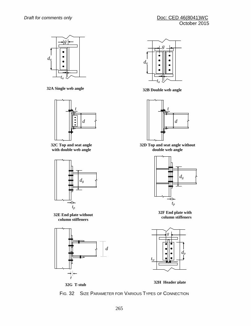
Draft for comments only Doc: CED 46(8041)WC October 2015
265
g
da
ta
FIG. 32 SIZE PARAMETER FOR VARIOUS TYPES OF CONNECTION
tp
dg
32C Top and seat angle
with double web angle
32E End plate without
column stiffeners
t
d
tp
dg
32F End plate with
column stiffeners
32G T-stub
da
ta
g
32A Single web angle 32B Double web angle
t
d
32D Top and seat angle without
double web angle
t
d
dp
tw
g
32H Header plate

Draft for comments only Doc: CED 46(8041)WC October 2015
266
FIG. 33 CLASSIFICATION OF CONNECTIONS ACCORDING TO BJORHOVDE
Table 43 Connection Classification Limits (Clause E-4.3.1)
Sl No. (1)
Nature of the Connection
(2)
In Terms of Strength
(3)
In Terms of Stiffness
(4)
i) Rigid connection
m1 > 0.7 m
1 > 2.5
1
ii) Semi-rigid connection
0.7> m1 > 0.2 2.5
1 > m
1 >0.5
1
iii) Flexible connection
m1 < 0.2 m
1 < 0.5
1
Rotation Capacity
m1 = (5.4-2θ
1)/3
1.0
R
IGID
SEMI-RIGID
FLEXIBLE
2.7 0
0.2
0.4
0.6
0.8
m1= M
/Mpb
θ1= θ / θ p

Draft for comments only Doc: CED 46(8041)WC October 2015
267
Table 44 Connection Constants in Frye-Morris Model (Clause E-4.3.2 and Fig. 32)
Sl
No.
(1)
Type
(2)
Connection type
(3)
Curve-fitting Constants
(4)
Standardization
Constants
(5) i) A Single web angle connection C1 = 1.91 x 10
4
C 2 = 1.30 x 10¹¹
C 3 = 2.70 x 10¹⁷
K = da-2.4tc
-1.81g0.15
ii) B Double web angle connection C 1 = 1.64 x 10³
C 2 = 1.03 x 10¹⁴
C 3 = 8.18 x 10
25
K = da-2.4 tc
-1.81g0.15
iii) C Top and seat angle connection with double web angle
C 1 = 2.24 x 10⁻¹
C 2 = 1.86 x 10
4
C 3 = 3.23 x 10⁸
K = d-1.287ta-1.128tc
-0.415
la-0.694(g –
0.5db)1.35
iv) D Top and seat angle connection without double web angle
C 1 = 1.63 x 10³
C 2 = 7.25 x 10¹⁴
C 3 = 3.31 x 10
23
K = d - 1.5 ta -0.5 la
- 0.7
db-1.1
v) E End plate connection without column stiffeners
C 1 = 1.78 x 10⁴
C 2 = -9.55 x 10¹⁶
C 3 = 5.54 x 10
29
K = dg- 2.4 tp
- 0.4 tf - 1.5
vi) F End plate connection with column stiffeners
C 1 = 2.60 x 10²
C 2 = 5.37 x 10¹¹
C 3 = 1.31 x 10
22
K = dg- 2.4 tp
- 0.6
vii) G T-stub connection C 1 = 4.05 x 10²
C 2 = 4.45 x 10¹³
C 3 = -2.03 x 10
23
K = d - 1.5 tf - 0.5 lt
- 0.7 db-
1.1
viii) H Header-plate connection C 1 = 3.87 C 2 = 2.71 x 10
5
C 3 = 6.06 x 10¹¹
K = tp-1.6 g1.6 db
-2.3 t w-
0.5
where d = depth of beam, in mm da= depth of the angle, in mm db= diameter of the bolt, in mm dg= center to center of the outermost bolt of the end plate connection, in mm g = gauge distance of bolt line, in mm ta = thickness of the top angle, in mm
tc = thickness of the web angle, in mm tf = thickness of flange T-stub connector, in mm tw= thickness of web of the beam in the connection, in mm tp= thickness of end plate, header plate, in mm la= length of the angle, in mm lt = length of the T-stub connector, in mm
NOTE – For preliminary analysis using a bilinear moment curvature relationship, the stiffness given in Table 45 may be assumed depending on the type of connection. The values are based on the secant stiffness at a rotation of 0.01 radian and typical dimension of connecting angle and other components as given in the Table.

Draft for comments only Doc: CED 46(8041)WC October 2015
268
Table 45 Secant Stiffness
(Table 42) SI No. (1)
Type of Connection
(2)
Dimension
mm
(3)
Secant
Stiffeness kNm/radian
(4)
i) Single web connection angle da = 250, ta = 10, g = 35
1 150
ii) Double web-angle connection
da = 250, ta = 10, g = 77.5
4 450
iii) Top and seat angle connection without double web angle connection
da=300, ta=10, la=140, db=20
2 730
iv) Header plate dp = 175, tp = 10, g = 75, tw = 7.5
2 300
E-5 COLUMN BASES E-5.1 Base Plates Columns shall be provided with base plates capable of distributing the compressive forces in the compressed parts of the column over a bearing area such that the bearing pressure on the foundation does not exceed the design strength of the point. The design strength of the joint between the base plate and the foundation shall be determined taking account of the material properties and dimensions of both the grout and the concrete foundation. E-5.2 Holding down bolts (Anchor Bolts) E-5.2.1 Holding down bolts shall be provided if necessary to resist the effects of the design loads. They shall be designed to resist tension due to uplift forces and tension due to bending moments as appropriate. E-5.2.2 When calculating the tension forces due to bending moments, the lever arm shall not be taken as more than the distance between the centroid of the bearing area

Draft for comments only Doc: CED 46(8041)WC October 2015
269
on the compression side and the centroid of the bolt group on the tension side, taking the tolerances on the positions of the holding down bolts into account. E-5.2.3 Holding down bolts shall either be anchored into the foundation by a hook or by a washer plate or by some other appropriate load distributing member embedded in the concrete. E-5.2.4 If no special elements for resisting the shear force are provided, such as block or bar shear connectors, it shall be demonstrated that sufficient resistance to transfer the shear force between the column and the foundation is provided by one of the following:
a) Frictional resistance of the joint between the base plate and the foundation. b) Shear resistance of the holding down bolts. c) Shear resistance of the surrounding part of the foundation. d) Shear and bearing resistance of the shear key plates welded to the base
plate and embedded in the pedestal/foundation.

Draft for comments only Doc: CED 46(8041)WC October 2015
270
ANNEX F (Clause 23.16)
GENERAL RECOMMENDATIONS FOR STEELWORK TENDERS AND
CONTRACTS F-1 GENERAL F-1.1 The recommendations given in this Annex are in line with those generally adopted for steelwork construction and are meant for general information. F-1.2 These recommendations do not form part of the requirements of the section and compliance with these is not necessary for the purpose of complying with this section. F-1.3 The recommendations are unsuitable for inclusion as a block requirement in a contract, but in drawing up a contract the points mentioned should be given consideration. F-2 EXCHANGE OF INFORMATION Before the steelwork design is commenced, the building designer should be satisfied that the planning of the building, its dimensions and other principal factors meet the requirements of the building owner and comply with regulations of all authorities concerned. Collaboration of building designer and steelwork designer should begin at the outset of the project by joint consideration of the planning and of such questions as the stanchion spacing, materials to be used for the construction, and depth of basement. F-3 INFORMATION REQUIRED BY THE STEELWORK DESIGNER F-3.1 General
a) Site plans showing in plan and elevation of the proposed location and main dimensions of the building or structure;
b) Ground levels, existing and proposed; c) Particulars of buildings or other constructions which may have to remain on the
actual site of the new building or structure during the erection of the steelwork; d) Particulars of adjacent buildings affecting, or affected by, the new work; e) Stipulation regarding the erection sequence or time schedule; f) Conditions affecting the position or continuity of members; g) Limits of length and weight of steel members in transit and erection; h) Drawings of the substructure, proposed or existing, showing:
1) levels of stanchion foundations, if already determined; 2) any details affecting the stanchion bases or anchor bolts; 3) permissible bearing pressure on the foundation; and

Draft for comments only Doc: CED 46(8041)WC October 2015
271
4) provisions for grouting.
NOTE— In the case of new work, the substructure should be designed in accordance with the relevant standards dealing with foundations and substructure.
j) The maximum wind velocity appropriate to the site (see Section 1 of Part 7); and k) Environmental factors, such as proximity to sea coast, and corrosive
atmosphere. Reference to bye-laws and regulations affecting the steelwork design and construction.
F-3.2 Further Information Relating to Buildings
a) Plans of the floors and roof with principal dimensions, elevations and cross-sections showing heights between floor levels.
b) The occupancy of the floors and the positions of any special loads should be given.
c) The building drawings, which should be fully dimensioned, should preferably be to the scale of 1 to 100 and should show all stairs, fire escapes, lifts, etc, suspended ceilings, flues and ducts for heating and ventilating. Doors and windows should be shown, as the openings may be taken into account in the computations of dead load.
Requirements should be given in respect of any maximum depth of beams or minimum head room.
Large-scale details should be given of any special features affecting the steelwork.
d) The inclusive weight per m2 of walls, floors, roofs, suspended ceilings, stairs and partitions, or particulars of their construction and finish for the computation of dead load.
The plans should indicate the floors, which are to be designed to carry partitions. Where the layout of partitions is not known, or a given layout is liable to alteration, these facts should be specially noted so that allowance may be made for partitions in any position (see Section 1 of Part 6).
e) The superimposed loads on the floors appropriate to the occupancy, as given in Section 1 of Part 6 or as otherwise required.
f) Details of special loads from cranes, runways, tips, lifts, bunkers, tanks, plant and equipment.
g) The grade of fire resistance appropriate to the occupancy as may be required. F-4 INFORMATION REQUIRED BY TENDERER (IF NOT ALSO DESIGNER) F-4.1 General
a) All information listed under F-3.1; b) Climatic conditions at site-seasonal variations of temperature, humidity, wind
velocity and direction; c) Nature of soil. Results of the investigation of sub-soil at site of building or
structure; d) Accessibility of site and details of power supply;
Draft for comments only Doc: CED 46(8041)WC October 2015
272
e) Whether the steelwork contractor will be required to survey the site and set out or check the building or structure lines, foundations and levels;
f) Setting-out plan of foundations, stanchions and levels of bases; g) Cross-sections and elevations of the steel structure, as necessary, with large-
scale details of special features; h) Whether the connections are to be bolted, riveted or welded. Particular attention
should be drawn to connections of a special nature, such as turned bolts, high strength friction grip bolts, long rivets and overhead welds;
j) Quality of steel, and provisions for identification; k) Requirements in respect of protective paintings at works and on site, galvanizing
or cement wash; m) Approximate dates for commencement and completion of erection; n) Details of any tests which have to be made during the course of erection or upon
completion; and p) Schedule of quantities. Where the tenderer is required to take off quantities, a list
should be given of the principal items to be included in the schedule.
F-4.2 Additional Information Relating to Buildings
a) Schedule of stanchions giving sizes, lengths and typical details of brackets, joints, etc;
b) Plan of grillages showing sizes, lengths and levels of grillage beams and particulars of any stiffeners required;
c) Plans of floor beams showing sizes, lengths and levels eccentricities and end moments. The beam reactions and details of the type of connection required should be shown on the plans;
d) Plan of roof steelwork. For a flat roof, the plan should give particulars similar to those of a floor plan. Where the roof is pitched, details should be given of trusses, portals, purlins, bracing, etc;
e) The steelwork drawings should preferably be to a scale of 1 to 100 and should give identification marks against all members; and
f) Particulars of holes required for services, pipes, machinery fixings, etc. Such holes should preferably be drilled at works.
F-4.3 Information Relating to Execution of Building Work
a) Supply of materials; b) Weight of steelwork for payment; c) Wastage of steel; d) Insurance, freight and transport from shop to site; e) Site facilities for erection; f) Tools and plants; g) Mode and terms of payment; h) Schedules;
Draft for comments only Doc: CED 46(8041)WC October 2015
273
j) Forced Majeure (sections and provisions for liquidation and damages for delay in completion); and
k) Escalation sections. F-5 DETAILING In addition to the number of copies of the approved drawings or details required under the contract, dimensioned shop drawings or details should be submitted in duplicate to the engineer who should retain one copy and return the other to the steel supplier or fabricators with his comments, if any. F-6 TIME SCHEDULE As the dates on which subsequent trades can commence, depend on the progress of erection of the steel framing, the time schedule for the latter should be carefully drawn up and agreed to by the parties concerned at a joint meeting. F-7 PROCEDURE ON SITE The steelwork contractor should be responsible for the positioning and Ievelling of all steelwork. Any checking or approval of the setting out by the general contractor or the engineer should not relieve the steelwork contractor of his responsibilities in this respect. F-8 INSPECTION References may be made to the good practice [6-6(42)] for general guidance. F-8.1 Access to Contractor’s Works The contractor should offer facilities for the inspection of the work at all stages. F-8.2 Inspection of Fabrication Unless otherwise, agreed, the inspection should be carried out at the place of fabrication. The contractor should be responsible for the accuracy of the work and for any error, which may be subsequently discovered. F-8.3 Inspection on Site To facilitate inspection, the contractor should during all working hours, have a foreman or properly accredited charge hand available on the site, together with a complete set of contract drawings and any further drawings and instructions which may have been issued from time to time.

Draft for comments only Doc: CED 46(8041)WC October 2015
274
F-9 MAINTENANCE F-9.1 General Where steelwork is to be encased in solid concrete, brickwork or masonry, the question of maintenance should not arise, but where steelwork is to be housed in hollow fire protection or is to be unprotected, particularly where the steelwork is exposed to a corroding agent, the question of painting or protective treatment of the steelwork should be given careful consideration at the construction stage, having regard to the special circumstances of the case. F-9.2 Connections Where connections are exposed to a corroding agent, they should be periodically inspected, and any corroded part should be thoroughly cleaned and painted. F-9.2.1 Where bolted connections are not solidly encased and are subject to vibratory effects of machinery or plant, they should be periodically inspected and all bolts tightened.
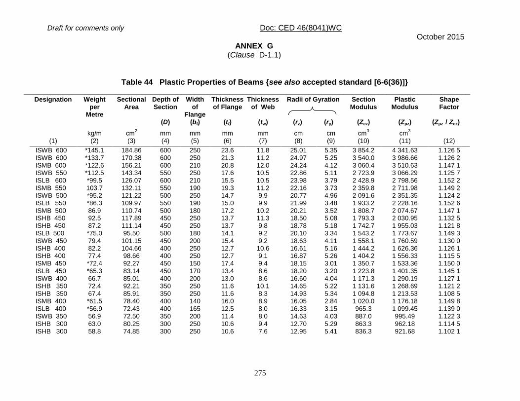
Draft for comments only Doc: CED 46(8041)WC October 2015
275
ANNEX G (Clause D-1.1)
Table 44 Plastic Properties of Beams {see also accepted standard [6-6(36)]} ______________________________________________________________________________________________________
Designation Weight per
Metre
Sectional Area
Depth of Section
(D)
Width of
Flange (bf)
Thickness of Flange
(tf)
Thickness of Web
(tw)
Radii of Gyration
(rz) (ry)
Section Modulus
(Zez)
Plastic Modulus
(Zpz)
Shape Factor
(Zpz / Zez)
(1)
kg/m (2)
cm2
(3)
mm (4)
mm (5)
mm (6)
mm (7)
cm (8)
cm (9)
cm3
(10) cm
3
(11)
(12)
ISWB 600 *145.1 184.86 600 250 23.6 11.8 25.01 5.35 3 854.2 4 341.63 1.126 5 ISWB 600 *133.7 170.38 600 250 21.3 11.2 24.97 5.25 3 540.0 3 986.66 1.126 2 ISMB 600 *122.6 156.21 600 210 20.8 12.0 24.24 4.12 3 060.4 3 510.63 1.147 1 ISWB 550 *112.5 143.34 550 250 17.6 10.5 22.86 5.11 2 723.9 3 066.29 1.125 7 ISLB 600 *99.5 126.07 600 210 15.5 10.5 23.98 3.79 2 428.9 2 798.56 1.152 2 ISMB 550 103.7 132.11 550 190 19.3 11.2 22.16 3.73 2 359.8 2 711.98 1.149 2 ISWB 500 *95.2 121.22 500 250 14.7 9.9 20.77 4.96 2 091.6 2 351.35 1.124 2 ISLB 550 *86.3 109.97 550 190 15.0 9.9 21.99 3.48 1 933.2 2 228.16 1.152 6 ISMB 500 86.9 110.74 500 180 17.2 10.2 20.21 3.52 1 808.7 2 074.67 1.147 1 ISHB 450 92.5 117.89 450 250 13.7 11.3 18.50 5.08 1 793.3 2 030.95 1.132 5 ISHB 450 87.2 111.14 450 250 13.7 9.8 18.78 5.18 1 742.7 1 955.03 1.121 8 ISLB 500 *75.0 95.50 500 180 14.1 9.2 20.10 3.34 1 543.2 1 773.67 1.149 3 ISWB 450 79.4 101.15 450 200 15.4 9.2 18.63 4.11 1 558.1 1 760.59 1.130 0 ISHB 400 82.2 104.66 400 250 12.7 10.6 16.61 5.16 1 444.2 1 626.36 1.126 1 ISHB 400 77.4 98.66 400 250 12.7 9.1 16.87 5.26 1 404.2 1 556.33 1.115 5 ISMB 450 *72.4 92.27 450 150 17.4 9.4 18.15 3.01 1 350.7 1 533.36 1.150 0 ISLB 450 *65.3 83.14 450 170 13.4 8.6 18.20 3.20 1 223.8 1 401.35 1.145 1 ISWB 400 66.7 85.01 400 200 13.0 8.6 16.60 4.04 1 171.3 1 290.19 1.127 1 ISHB 350 72.4 92.21 350 250 11.6 10.1 14.65 5.22 1 131.6 1 268.69 1.121 2 ISHB 350 67.4 85.91 350 250 11.6 8.3 14.93 5.34 1 094.8 1 213.53 1.108 5 ISMB 400 *61.5 78.40 400 140 16.0 8.9 16.05 2.84 1 020.0 1 176.18 1.149 8 ISLB 400 *56.9 72.43 400 165 12.5 8.0 16.33 3.15 965.3 1 099.45 1.139 0 ISWB 350 56.9 72.50 350 200 11.4 8.0 14.63 4.03 887.0 995.49 1.122 3 ISHB 300 63.0 80.25 300 250 10.6 9.4 12.70 5.29 863.3 962.18 1.114 5 ISHB 300 58.8 74.85 300 250 10.6 7.6 12.95 5.41 836.3 921.68 1.102 1

Draft for comments only Doc: CED 46(8041)WC October 2015
276
Designation Weight per
Metre
Sectional Area
Depth of Section
(D)
Width of
Flange (bf)
Thickness of Flange
(tf)
Thickness of Web
(tw)
Radii of Gyration
(rz) (ry)
Section Modulus
(Zez)
Plastic Modulus
(Zpz)
Shape Factor
(Zpz / Zez)
(1)
kg/m (2)
cm2
(3)
mm (4)
mm (5)
mm (6)
mm (7)
cm (8)
cm (9)
cm3
(10) cm
3
(11)
(12)
ISMC 400 *49.4 62.93 400 100 15.3 8.6 15.48 2.83 754.1 891.03 1.181 6 ISMB 350 52.4 66.70 350 140 14.2 8.1 14.32 2.84 779.0 889.57 1.142 1 ISLB 350 49.5 63.01 350 165 11.4 7.4 14.45 3.17 751.9 851.11 1.132 0 ISLC 400 *45.7 58.25 400 100 14.0 8.0 15.50 2.81 699.5 825.02 1.179 4 ISWB 300 48.1 61.33 300 200 10.0 7.4 12.66 4.02 654.8 731.21 1.116 7 ISHB 250 54.7 69.71 250 250 9.7 8.8 10.70 5.37 638.7 708.43 1.109 2 ISLB 325 *43.1 54.90 325 165 9.8 7.0 13.41 3.05 607.7 687.76 1.131 7 ISHB 250 51.0 64.96 250 250 9.7 6.9 10.91 5.49 618.9 678.73 1.096 7 ISMC 350 *42.1 53.66 350 100 13.5 8.1 13.66 2.83 571.9 672.19 1.175 4 ISMB 300 *44.2 56.26 300 140 12.4 7.5 12.37 2.84 573.6 651.74 1.136 2 ISLC 350 *38.8 49.47 350 100 12.5 7.4 13.72 2.82 532.1 622.95 1.170 7 ISLB 300 *37.7 48.08 300 150 9.4 6.7 12.35 2.80 488.9 554.32 1.133 8 ISHB 225 ISWB 250 ISHB 225
46.8 40.9 43.1
59.66 52.05 54.94
225 250 225
225 200 225
9.1 9.0 9.1
8.6 6.7 6.5
9.58 10.69 9.80
4.84 4.06 4.96
487.0 475.4 469.3
542.22 527.57 515.82
1.113 4 1.109 7 1.098 7
ISMC 300 *35.8 45.64 300 90 13.6 7.6 11.81 2.61 424.2 496.77 1.171 1 ISMB 250 37.3 47.55 250 125 12.5 6.9 10.39 2.65 410.5 465.71 1.134 5 ISLC 300 *33.1 42.11 300 100 11.6 6.7 11.98 2.87 403.2 466.73 1.157 6 ISLB 275 *33.0 42.02 275 140 8.8 6.4 11.31 2.61 392.4 443.09 1.130 5 ISHB 200 40.0 50.94 200 200 9.0 7.8 8.55 4.42 372.2 414.23 1.112 9 ISHB 200 37.3 47.54 200 200 9.0 6.1 8.71 4.51 360.8 397.23 1.101 0 ISWB 225 33.9 43.24 225 150 9.9 6.4 9.52 3.22 348.5 389.93 1.118 9 ISMC 250 *30.4 38.67 250 80 14.1 7.1 9.94 2.38 305.3 356.72 1.168 4 ISMB 225 31.2 39.72 225 110 11.8 6.5 9.31 2.34 305.9 348.27 1.138 5 ISLB 250 *27.9 35.53 250 125 8.2 6.1 10.23 2.33 297.4 338.69 1.138 8 ISLC 250 28.0 35.65 250 100 10.7 6.1 10.17 2.89 295.0 338.11 1.146 2 ISWB 200 28.8 36.71 200 140 9.0 6.1 8.46 2.99 262.5 293.99 1.120 0 ISMC 225 *25.9 33.01 225 80 12.4 6.4 9.03 2.38 239.5 277.93 1.160 5 ISLC 225 *24.0 30.53 225 90 10.2 5.8 9.14 2.62 226.5 260.13 1.148 5 ISLB 225 *23.5 29.92 225 100 8.6 5.8 9.15 1.94 222.4 254.72 1.145 3 ISMB 200 25.4 32.33 200 100 10.8 5.7 8.32 2.15 223.5 253.86 1.135 8 ISHB 150 34.6 44.08 150 150 9.0 11.8 6.09 3.35 218.1 251.64 1.153 8 ISHB 150 30.6 38.98 150 150 9.0 8.4 6.29 3.44 205.3 232.52 1.132 6

Draft for comments only Doc: CED 46(8041)WC October 2015
277
Designation Weight per
Metre
Sectional Area
Depth of Section
(D)
Width of
Flange (bf)
Thickness of Flange
(tf)
Thickness of Web
(tw)
Radii of Gyration
(rz) (ry)
Section Modulus
(Zez)
Plastic Modulus
(Zpz)
Shape Factor
(Zpz / Zez)
(1)
kg/m (2)
cm2
(3)
mm (4)
mm (5)
mm (6)
mm (7)
cm (8)
cm (9)
cm3
(10) cm
3
(11)
(12)
ISHB 150 27.1 34.48 150 150 9.0 5.4 6.50 3.54 194.1 215.64 1.111 0 ISMC 200 *22.1 28.21 200 75 11.4 6.1 8.03 2.23 181.9 211.25 1.161 4 ISLC 200 *20.6 26.22 200 75 10.8 5.5 8.11 2.37 172.6 198.77 1.151 6 ISWB 175 22.1 28.11 175 125 7.4 5.8 7.33 2.59 172.5 194.20 1.125 8 ISLB 200 *19.8 25.27 200 100 7.3 5.4 8.19 2.13 169.7 184.34 1.137 0 ISMB 175 *19.3 24.62 175 90 8.6 5.5 7.19 1.86 145.4 166.08 1.142 2 ISMC 175 *19.1 24.38 175 75 10.2 5.7 7.08 2.23 139.8 161.65 1.156 3 ISLC 175 *17.6 22.40 175 75 9.5 5.1 7.16 2.38 131.3 150.36 1.145 2
ISLB 175 *16.7 21.30 175 90 6.9 5.1 7.17 1.93 125.3 143.30 1.143 7
ISJB 225 *12.8 16.28 225 80 5.0 3.7 8.97 1.58 116.3 134.15 1.153 5 ISJC 200 13.9 17.80 200 70 7.1 4.1 8.08 2.18 116.1 133.12 1.146 5 ISWB 150 17.0 21.67 150 100 7.0 5.4 6.22 2.09 111.9 126.86 1.133 7 ISMC 150 16.4 20.88 150 75 9.0 5.4 6.11 2.21 103.9 119.82 1.153 3 ISMB 150 14.9 19.00 150 80 7.6 4.8 6.18 1.66 96.9 110.48 1.140 1 ISLC 150 ISLB 150 ISJC 175
14.4 14.2 *11.2
18.36 18.08 14.24
150 150 175
75 80 60
7.8 6.8 6.9
4.8 4.8 3.6
6.16 6.17 7.11
2.37 1.75 1.88
93.0 91.8 82.3
106.17 104.50 94.22
1.141 6 1.138 4 1.144 9
ISJB 200 *9.9 12.64 200 60 5.0 3.4 7.86 1.17 78.1 90.89 1.163 9 ISMB 125 13.0 16.60 125 75 7.6 4.4 5.20 1.62 71.8 81.85 1.139 9 ISMC 125 12.7 16.19 125 65 8.1 5.0 5.07 1.92 66.6 77.15 1.158 5 ISLB 125 11.9 15.12 125 75 6.5 4.4 5.19 1.69 65.1 73.93 1.135 6 ISJC 150 9.9 12.65 150 55 6.9 3.6 6.90 1.73 62.8 72.04 1.147 2 ISLC 125 10.7 13.67 125 65 6.6 4.4 5.11 2.05 57.1 65.45 1.146 2 ISJB 175 *8.1 10.28 175 50 4.6 3.0 6.83 0.97 54.8 64.22 1.179 9 ISMB 100 11.5 14.60 100 75 7.2 4.0 4.20 1.05 36.6 41.68 1.138 9 ISJB 150 *7.1 9.01 150 50 4.6 3.0 5.98 1.01 42.9 49.57 1.155 6 ISJC 125 7.9 10.07 125 50 6.6 3.0 5.18 1.60 43.2 49.08 1.136 2 ISMC 100 9.2 11.70 100 50 7.5 4.7 4.00 1.49 37.3 43.83 1.175 0 ISLB 100 8.0 10.21 100 50 6.4 4.0 4.06 1.12 33.6 38.89 1.157 3 ISLC 100 7.9 10.02 100 50 6.4 4.0 4.06 1.57 32.9 38.09 1.157 6 ISJC 100 *5.8 7.41 100 45 5.1 3.0 4.09 1.42 24.8 28.38 1.144 2 ISMC 75 6.8 8.67 75 40 7.3 4.4 2.96 1.21 20.8 24.17 1.190 4

Draft for comments only Doc: CED 46(8041)WC October 2015
278
Designation Weight per
Metre
Sectional Area
Depth of Section
(D)
Width of
Flange (bf)
Thickness of Flange
(tf)
Thickness of Web
(tw)
Radii of Gyration
(rz) (ry)
Section Modulus
(Zez)
Plastic Modulus
(Zpz)
Shape Factor
(Zpz / Zez)
(1)
kg/m (2)
cm2
(3)
mm (4)
mm (5)
mm (6)
mm (7)
cm (8)
cm (9)
cm3
(10) cm
3
(11)
(12)
ISLB 75 6.1 7.71 75 50 5.0 3.7 3.07 1.14 19.4 22.35 1.152 2 ISLC 75 *5.7 7.26 75 40 6.0 3.7 3.02 1.26 17.6 20.61 1.171 0
NOTE – Sections having ‘weight per meter’ marked with an asterisk(*) may be chosen as the section is lighter having high Zp as compared to sections below it.

Draft for comments only Doc: CED 46(8041)WC October 2015
279
LIST OF STANDARDS The following list records those standards which are acceptable as 'good practice’ and 'accepted standards’ in the fulfillment of the requirements of the Code. The latest version of a standard shall be adopted at the time of enforcement of the Code. The standards listed may be used by the Authority as a guide in conformance with the requirements of the referred clauses in the Code. In the following list, the number appearing in the first column within parentheses indicates the number of the reference in this Part/Section. (1) 786:1967 Conversion factors and conversion tables (first revision)
(2) 808 : 1989 Dimensions for hot-rolled steel beam, column, channel and
angle sections (third revision)
1852 : 1985 Rolling and cutting tolerance for hot rolled steel products (fourth revision)
(3) IS 8000 Geometrical tolerancing on technical drawings (second revision)
(Part 1):1985 Tolerances of form, orientation, location and run-out, and appropriate geometrical definitions (first revision)
(Part 2):1992 Maximum material principles (first revision)
(Part 3):1992 Dimensioning and tolerancing of profiles (second revision)
(Part 4):1976 Practical examples of indications on drawings
IS 8976:1978 Guide for preparation and arrangement of sets of drawings and parts list
962 : 1989 Code of practice for architectural and building drawings (second revision)
(4) 962 : 1989 Code of practice for architectural and building drawings (second revision)
(5) 813 : 1986 Scheme of symbols for welding
(6) 2062 : 2011 Hot rolled low, medium and high tensile structural steel (seventh revision)
(7) 1608 : 2006/ ISO 6892:1998
Metallic materials – Tensile testing at ambient temperatures (third revision)
(8) 1161 : 2014 Steel Tubes for Structural Purposes ( Fifth Revision )
(9) 814 : 2004 Covered Electrodes for Manual Metal Arc Welding of Carbon and Carbon Manganese Steel – Specification (sixth revision)
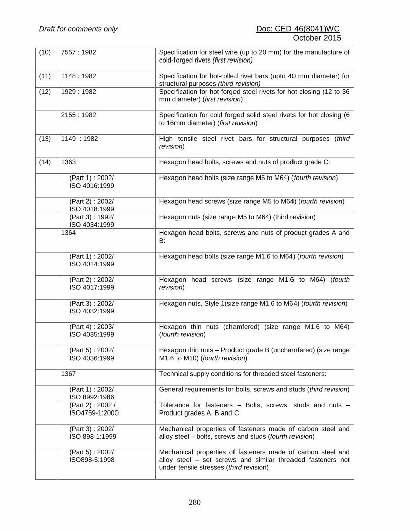
Draft for comments only Doc: CED 46(8041)WC October 2015
280
(10) 7557 : 1982 Specification for steel wire (up to 20 mm) for the manufacture of cold-forged rivets (first revision)
(11) 1148 : 1982 Specification for hot-rolled rivet bars (upto 40 mm diameter) for structural purposes (third revision)
(12) 1929 : 1982 Specification for hot forged steel rivets for hot closing (12 to 36 mm diameter) (first revision)
2155 : 1982 Specification for cold forged solid steel rivets for hot closing (6 to 16mm diameter) (first revision)
(13) 1149 : 1982 High tensile steel rivet bars for structural purposes (third revision)
(14) 1363 Hexagon head bolts, screws and nuts of product grade C:
(Part 1) : 2002/ ISO 4016:1999
Hexagon head bolts (size range M5 to M64) (fourth revision)
(Part 2) : 2002/ ISO 4018:1999
Hexagon head screws (size range M5 to M64) (fourth revision)
(Part 3) : 1992/ ISO 4034:1999
Hexagon nuts (size range M5 to M64) (third revision)
1364 Hexagon head bolts, screws and nuts of product grades A and B:
(Part 1) : 2002/ ISO 4014:1999
Hexagon head bolts (size range M1.6 to M64) (fourth revision)
(Part 2) : 2002/ ISO 4017:1999
Hexagon head screws (size range M1.6 to M64) (fourth revision)
(Part 3) : 2002/ ISO 4032:1999
Hexagon nuts, Style 1(size range M1.6 to M64) (fourth revision)
(Part 4) : 2003/ ISO 4035:1999
Hexagon thin nuts (chamfered) (size range M1.6 to M64) (fourth revision)
(Part 5) : 2002/ ISO 4036:1999
Hexagon thin nuts – Product grade B (unchamfered) (size range M1.6 to M10) (fourth revision)
1367 Technical supply conditions for threaded steel fasteners:
(Part 1) : 2002/ ISO 8992:1986
General requirements for bolts, screws and studs (third revision)
(Part 2) : 2002 / ISO4759-1:2000
Tolerance for fasteners – Bolts, screws, studs and nuts – Product grades A, B and C
(Part 3) : 2002/ ISO 898-1:1999
Mechanical properties of fasteners made of carbon steel and alloy steel – bolts, screws and studs (fourth revision)
(Part 5) : 2002/ ISO898-5:1998
Mechanical properties of fasteners made of carbon steel and alloy steel – set screws and similar threaded fasteners not under tensile stresses (third revision)
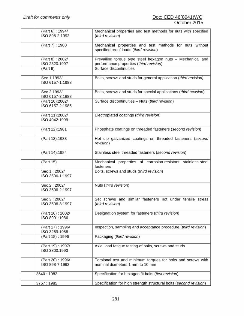
Draft for comments only Doc: CED 46(8041)WC October 2015
281
(Part 6) : 1994/ ISO 898-2:1992
Mechanical properties and test methods for nuts with specified (third revision)
(Part 7) : 1980 Mechanical properties and test methods for nuts without specified proof loads (third revision)
(Part 8) : 2002/ ISO 2320:1997
Prevailing torque type steel hexagon nuts – Mechanical and performance properties (third revision)
(Part 9) Surface discontinuities
Sec 1:1993/ ISO 6157-1:1988
Bolts, screws and studs for general application (third revision)
Sec 2:1993/ ISO 6157-3:1988
Bolts, screws and studs for special applications (third revision)
(Part 10):2002/ ISO 6157-2:1985
Surface discontinuities – Nuts (third revision)
(Part 11):2002/ ISO 4042:1999
Electroplated coatings (third revision)
(Part 12):1981 Phosphate coatings on threaded fasteners (second revision)
(Part 13):1983 Hot dip galvanized coatings on threaded fasteners (second revision)
(Part 14):1984
Stainless steel threaded fasteners (second revision)
(Part 15) Mechanical properties of corrosion-resistant stainless-steel fasteners
Sec 1 : 2002/ ISO 3506-1:1997
Bolts, screws and studs (third revision)
Sec 2 : 2002/ ISO 3506-2:1997
Nuts (third revision)
Sec 3 : 2002/ ISO 3506-3:1997
Set screws and similar fasteners not under tensile stress (third revision)
(Part 16) : 2002/ ISO 8991:1986
Designation system for fasteners (third revision)
(Part 17) : 1996/ ISO 3269:1988
Inspection, sampling and acceptance procedure (third revision)
(Part 18) : 1996 Packaging (third revision)
(Part 19) : 1997/ ISO 3800:1993
Axial load fatigue testing of bolts, screws and studs
(Part 20) : 1996/ ISO 898-7:1992
Torsional test and minimum torques for bolts and screws with nominal diameters 1 mm to 10 mm
3640 : 1982 Specification for hexagon fit bolts (first revision)
3757 : 1985 Specification for high strength structural bolts (second revision)

Draft for comments only Doc: CED 46(8041)WC October 2015
282
5369 : 1975 General requirements for plain washers and lock washers (first revision)
5370 : 1969 Specification for plain washers with outside diameter 3 inside diameter
5372 : 1975 Taper washer for channels (ISMC) (first revision)
5374 : 1975 Taper washers for I-beams (ISMB) (first revision)
5624 : 1993 Foundation Bolts – Specification (first revision)
6610:1972 Specification for heavy washers for steel structures
6623:1985 Specification for high strength structural nuts (first revision)
6639:1972 Specification for hexagon bolts for steel structures
649:1985 Specification for hardened and tempered washers for high strength structural bolts and nuts (first revision)
(15) 4000 : 1992 Code of practice for high strength bolts in steel structures (first revision)
(16) 1030 : 1998 Carbon steel castings for general engineering purposes (fifth revision)
(17) 2708 : 1993 1.5 percent manganese steel castings for general engineering purpose (third revision)
(18) 814 : 2004 Covered electrodes for manual metal arc welding of carbon and carbon manganese steel - Specification (fifth revision)
(19) 1395 : 1982 Low and medium alloy steel covered electrodes for manual metal arc welding (third revision)
(20) 1278 : 1972 Specification for filler rods and wires for gas welding (second revision)
(21) 1387 : 1993 General requirements for the supply of metallurgical materials (second revision)
(22) IS 7280:1974 Specification for bare wire electrodes for submerged arc welding of structural steels
(23) 3613 : 1974 Acceptance tests for wire flux combination for submerged arc welding (first revision)
(24) 6419 : 1996 Welding rods and bare electrodes for gas shielded arc welding of structural steel (first revision)
6560 : 1996 Molybdenum chromium-molybdenum low alloy steel welding rods and bare electrodes for gas shielded arc welding (first revision)
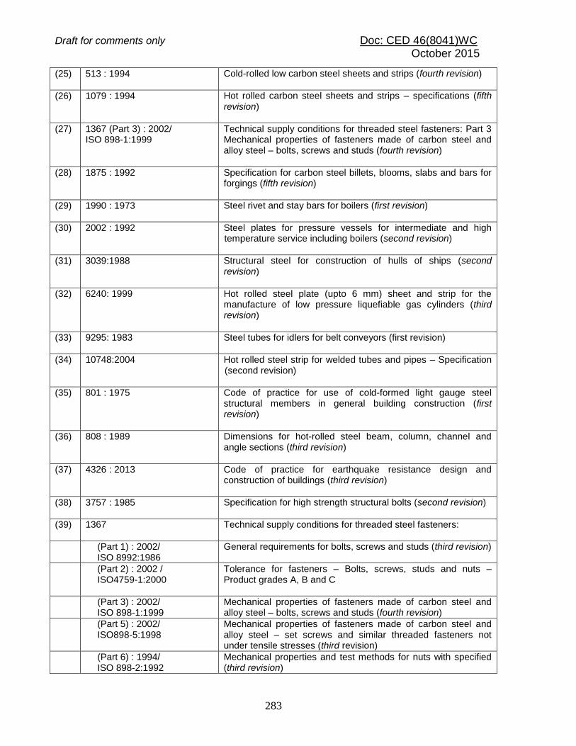
Draft for comments only Doc: CED 46(8041)WC October 2015
283
(25) 513 : 1994 Cold-rolled low carbon steel sheets and strips (fourth revision)
(26) 1079 : 1994 Hot rolled carbon steel sheets and strips – specifications (fifth revision)
(27) 1367 (Part 3) : 2002/ ISO 898-1:1999
Technical supply conditions for threaded steel fasteners: Part 3 Mechanical properties of fasteners made of carbon steel and alloy steel – bolts, screws and studs (fourth revision)
(28) 1875 : 1992 Specification for carbon steel billets, blooms, slabs and bars for forgings (fifth revision)
(29) 1990 : 1973 Steel rivet and stay bars for boilers (first revision)
(30) 2002 : 1992 Steel plates for pressure vessels for intermediate and high temperature service including boilers (second revision)
(31) 3039:1988 Structural steel for construction of hulls of ships (second revision)
(32) 6240: 1999 Hot rolled steel plate (upto 6 mm) sheet and strip for the manufacture of low pressure liquefiable gas cylinders (third revision)
(33) 9295: 1983 Steel tubes for idlers for belt conveyors (first revision)
(34) 10748:2004 Hot rolled steel strip for welded tubes and pipes – Specification (second revision)
(35) 801 : 1975
Code of practice for use of cold-formed light gauge steel structural members in general building construction (first revision)
(36) 808 : 1989 Dimensions for hot-rolled steel beam, column, channel and angle sections (third revision)
(37) 4326 : 2013 Code of practice for earthquake resistance design and construction of buildings (third revision)
(38) 3757 : 1985 Specification for high strength structural bolts (second revision)
(39) 1367 Technical supply conditions for threaded steel fasteners:
(Part 1) : 2002/ ISO 8992:1986
General requirements for bolts, screws and studs (third revision)
(Part 2) : 2002 / ISO4759-1:2000
Tolerance for fasteners – Bolts, screws, studs and nuts – Product grades A, B and C
(Part 3) : 2002/ ISO 898-1:1999
Mechanical properties of fasteners made of carbon steel and alloy steel – bolts, screws and studs (fourth revision)
(Part 5) : 2002/ ISO898-5:1998
Mechanical properties of fasteners made of carbon steel and alloy steel – set screws and similar threaded fasteners not under tensile stresses (third revision)
(Part 6) : 1994/ ISO 898-2:1992
Mechanical properties and test methods for nuts with specified (third revision)

Draft for comments only Doc: CED 46(8041)WC October 2015
284
(Part 7) : 1980 Mechanical properties and test methods for nuts without specified proof loads (third revision)
(Part 8) : 2002/ ISO 2320:1997
Prevailing torque type steel hexagon nuts – Mechanical and performance properties (third revision)
(Part 9) Surface discontinuities
Sec 1:1993/ ISO 6157-1:1988
Bolts, screws and studs for general application (third revision)
Sec 2:1993/ ISO 6157-3:1988
Bolts, screws and studs for special applications (third revision)
(Part 10):2002/ ISO 6157-2:1985
Surface discontinuities – Nuts (third revision)
(Part 11):2002/ ISO 4042:1999
Electroplated coatings (third revision)
(Part 12):1981 Phosphate coatings on threaded fasteners (second revision)
(Part 13):1983 Hot dip galvanized coatings on threaded fasteners (second revision)
(Part 14):1984
Stainless steel threaded fasteners (second revision)
(Part 15) Mechanical properties of corrosion-resistant stainless-steel fasteners
Sec 1 : 2002/ ISO 3506-1:1997
Bolts, screws and studs (third revision)
Sec 2 : 2002/ ISO 3506-2:1997
Nuts (third revision)
Sec 3 : 2002/ ISO 3506-3:1997
Set screws and similar fasteners not under tensile stress (third revision)
(Part 16) : 2002/ ISO 8991:1986
Designation system for fasteners (third revision)
(Part 17) : 1996/ ISO 3269:1988
Inspection, sampling and acceptance procedure (third revision)
(Part 18) : 1996 Packaging (third revision)
(Part 19) : 1997/ ISO 3800:1993
Axial load fatigue testing of bolts, screws and studs
(Part 20) : 1996/ ISO 898-7:1992
Torsional test and minimum torques for bolts and screws with nominal diameters 1 mm to 10 mm
(40) 816 : 1969 Code of practice for use of metal arc welding for general construction in mild steel (first revision)
9595:1996 Metal arc welding of carbon and carbon manganese steels- Recommendations (first revision)

Draft for comments only Doc: CED 46(8041)WC October 2015
285
(41) 9077 : 1979 Code of practice for corrosion protection of steel reinforcement in RB and RCC construction
9172:1979 Recommended design practice for corrosion prevention of steel structures
(42) 7215 : 1974 Tolerances for fabrication of steel structures
(43) 12843 : 1989 Tolerances for erection of steel structures
(44) 9595:1996 Metal arc welding of carbon and carbon manganese steels- Recommendations (first revision)
(45) 919 ISO systems of limits and fits:
(Part 1) : 1993/ ISO 286-1:1988
Bases of tolerance, deviations and fits (second revision)
(Part 2) : 1993/ ISO 286-2:1988
Tables of standard tolerance grades and limit deviations for holes and shafts (first revision)
(46) 816 : 1969 Code of practice for use of metal arc welding for general construction in mild steel (first revision)
819 : 1957 Code of practice for resistance spot welding for light assemblies in mild steel
1024 : 1999 Code of practice for use of welding in bridges and structures subject to dynamic loading (second revision)
1261 : 1959 Code of practice for seam welding in mild steel
1323 : 1982 Code of practice for oxy-acetylene welding for structural work in mild steels (second revision)
9595:1996 Metal arc welding of carbon and carbon manganese steels- Recommendations (first revision)
(47) 817 Training of welders – Code of Practice
(Part 1): 1966
Manual metal arc welding (second revision)
(Part 2) : 1996 Oxyfuel welding (second revision)
1393 : 1961 Code of practice for training and testing of oxy-acetylene welders
7307 (Part 1) : 1974 Approval tests for welding procedures: Part 1 Fusion welding of steel
7310 (Part 1):1974 Approval tests for welders working to approved welding procedures- Part 1 Fusion welding of steel
7318 (Part 1):1974 Approval tests for welders when welding procedure approval is not required: Part 1 Fusion welding of steel

Draft for comments only Doc: CED 46(8041)WC October 2015
286
(48) 1477 Code of practice for painting of ferrous metals in buildings:
(Part 1) : 2000 Pre-treatment (second revision)
(Part 2) : 1971 Painting (first revision)
(49) 7205 : 1974 Safety code for erection of structural steelwork
(50) 456 : 2000 Plain and reinforced concrete - Code of practice (fourth revision)
SP 6 (Part 1) : 1964
Handbook for Structural Engineers - Structural Steel Sections