Embed Size (px)
Citation preview

MANAK BHAVAN, 9 BAHADUR SHAH ZAFAR MARG, NEW DELHI 110002
DOCUMENT DESPATCH ADVICE
TECHNICAL COMMITTEE: Building Limes and Gypsum Products Sectional Committee, CED 4
ADDRESSED TO:
1. All Members of Civil Engineering Division Council, CEDC 2. All Members of CED 4 3. All others interests
Dear Sir(s),
Please find enclosed the following draft:
Doc. No. Title
CED 4(7782) Draft Indian Standard Code of Practice for Dry Lining and Partitioning using Gypsum Plasterboard
Kindly examine the draft and forward your views stating any difficulties which you are likely to
experience in your business or profession if this is finally adopted as National Standard. Last Date for comments: 15 November 2011.
Comments if any, may please be made in the format as attached, and mailed to the undersigned at the above address. You are requested to send your comments preferably through e-mail to [email protected].
In case no comments are received or comments received are of editorial nature, you may kindly permit
us to presume your approval for the above document as finalized. However, in case of comments of technical nature are received then it may be finalized either in consultation with the Chairman, Sectional Committee or referred to the Sectional Committee for further necessary action if so desired by the Chairman, Sectional Committee.
This document is also hosted on BIS website www.bis.org.in.
Thanking you, Yours faithfully,
(A.K. Saini) Sc ‘F’ and Head (Civil Engg) Encl: as above Tele/Fax: 011 23235529
DRAFT IN WIDE CIRCULATION
Reference Date
CED 4/T-70 15 September 2011
FORMAT FOR SENDING COMMENTS ON BIS DOCUMENT
[Please use A4 size sheet of paper only and type within fields indicated. Information in column (3) should include reasons for comments, technical references and suggestions for modified wording of the clause when the existing
text is found not acceptable. Comments through e-mail ([email protected]) shall be appreciated.]
Name of the Commentator/ Organization: ______________________________________ BIS Document No.:__CED 4(7782)WC____ Title:___ Wide Circulation Draft Indian Standard DRY LINING AND PARTITIONING USING
GYPSUM PLASTERBOARD – CODE OF PRACTICE
BIS Letter Reference No.____CED 4/T-70_______ Dated___15 September 2011__
Clause/ Table No.
Comments/ Modified Wordings
Justification of Proposed Change
(1) (2) (3)
CED4(7782)WC – Wide Circulation Draft FOR BIS USE ONLY
1
BUREAU OF INDIAN STANDARDS
Draft Indian Standard (Not to be reproduced without the permission of BIS or used as an Indian Standard)
DRY LINING AND PARTITIONING USING GYPSUM PLASTERBOARD
– CODE OF PRACTICE Doc: CED 4(7782)WC
Building Limes and Gypsum Products Last Date for Comments Sectional Committee, CED 4 15 November 2011
FOREWORD
0.1 Formal clause will be added later on. 0.2 The internal surfaces of walls and ceilings of most of the buildings are finished internally by applying plaster in one or more coats. In order to reduce the demand of site labour, the use of building board, such as gypsum plaster board, fibre hard board, cement coir board and asbestos cement building board as covering for walls and ceiling is increasing steadily. Gypsum boards have the specific advantage of being lighter than the boards of similar nature, such as fibre hard boards and asbestos cement building boards. Gypsum boards also possess better fire-resisting, thermal and sound insulating properties. 0.3 Gypsum boards are manufactured as plain, laminated and reinforced boards. Reinforcing materials generally used as glass, paper, vegetable fibres, etc. The boards may be used to provide dry lining finishes to masonry walls, to ceilings, to steel or timber frame partitions, or as ceilings to structural steel columns and beams, or in the manufacture of prefabricated partition panels. Laminated gypsum boards are used for laying for concrete ceiling. With concrete it combines firmly and represents readymade interior plastering. Specifications of Gypsum boards have been covered in three parts to IS 2095. Part 1 covers plain boards, Part 2 covers laminated/coated boards, and Part 3 covers reinforced boards.
0.4 This standard is intended chiefly to cover the technical provisions relating to fixing of gypsum boards by nailing, screwing, etc or sticking with gypsum based or other adhesives. The provisions were intended to provide the users of this standard, comprehensive information than those in IS 1414:1989 ‘Code of practice for fixing of wall coverings (first revision).
0.5 Dry lining is an alternative to the traditional wet plastering of walls and ceilings to provide surfaces suitable to receive various decorative treatments. The method involves the fixing of a sheet material, which is subsequently jointed in the appropriate manner, to the face of the walls or ceilings. This standard confines itself to recommendations for dry lining using gypsum boards; it is not intended to apply to other sheet materials.
0.6 This standard provides guidance on the selection of a dry lining system and lists factors that should be taken into consideration in the selection process. It gives recommendations for methods of dry lining to a variety of solid backgrounds and to timber and metal framing. Recommendations for on site methods of working are also included together with detailed descriptions of the materials, components and accessories used in the dry lining process.
0.7 This draft Indian standard is developed to suit Indian context and is based on the technical provisions as given in BS 8212:1995 ‘Code of practice for dry lining and partitioning using gypsum plasterboard’.
0.8 For the purpose of deciding whether a particular requirement of this standard is complied with, the final value, observed or calculated, expressing the result of a measurement shall be rounded off in accordance with IS 2 : 1960 ‘Rules for rounding off numerical values (revised)’. The number of significant places retained in the rounded off value should be the same as that of the specified value in this standard.

CED4(7782)WC – Wide Circulation Draft FOR BIS USE ONLY
2
Draft Indian Standard
(Not to be reproduced without the permission of BIS or used as an Indian Standard)
DRY LINING AND PARTITIONING USING GYPSUM PLASTERBOARDS
– CODE OF PRACTICE Doc: CED 4(7782)WC
Section 1 General 1.1 Scope This Indian Standard code of practice gives recommendations for dry lining walls, ceilings and partitioning using gypsum plasterboards. Composite products such as gypsum plasterboard backed with insulation materials are also included. This code does not deal with linings to heated ceilings. 1.2 References The Indian standards listed in Annex A contain provision which through reference in this text, constitute provisions of this standard. At the time of publication, the editions indicated were valid. All standards are subject to revision and parties to agreement based on this standard are encouraged to investigate the possibility of applying the most recent editions of the standards indicated therein. 1.3 Definitions For the purposes of this code the definitions given in IS 2469, IS 2547 (Part 1), IS 2547 (Part 2), IS 2095 (Part 1), IS 2095 (Part 2) and IS 2095 (Part 3) shall apply. 1.3.1 Face Surface of gypsum plasterboard on which the paper extends continuously to cover the edges. 1.3.2 Back Surface of gypsum plasterboard having a double thickness of paper along the two edges. 1.3.3 Insulating Gypsum Wallboard Gypsum wallboard backed with a film having a surface of low emissivity, e.g. aluminium, to improve thermal insulation when used in conjunction with an air space. 1.3.4 Thermal Wallboard Laminate Gypsum wallboard backed with an insulating material such as expanded polystyrene, polyurethane, phenol formaldehyde foam or synthetic mineral fibre materials. 1.3.5 Predecorated Gypsum Wallboard Gypsum wallboard faced with either paper or cloth backed vinyl film.

CED4(7782)WC – Wide Circulation Draft FOR BIS USE ONLY
3
1.3.6 Laminated Gypsum Plasterboard Partitions Three or more layers of gypsum wallboard bonded together and fixed at the perimeter to a steel or timber frame. 1.3.7 Relocatable Partitions Partitions that permit reassembly after removal and relocation. 1.3.8 Metal Furring Channel Galvanized steel section for the attachment of wallboard linings to solid backgrounds. 1.3.9 Resilient Fixing Channel Galvanized steel section for securing gypsum wallboard to the supporting background by a resilient mounting. 1.3.10 Nailable Fixing Plug Galvanized steel nail with an expandable plastics sleeve. 1.3.11 General Purpose Bonding Compound Adhesive made from retarded calcium sulfate hemihydrate and additives. 1.3.12 Thermal Wallboard Laminate Adhesive Adhesive made from synthetic resin emulsion with fillers used for bonding thermal wallboard laminates to plastered walls. 1.3.13 Resilient Wallboard Adhesive Adhesive made from synthetic rubber/resin used to bond plasterboard to plasterboard. 1.3.14 Decorative Textured Coating Plastics based textured coating used as a decorative finish. 1.4 Exchange of Information When preparing dry lining details the designer should take into account the following points.
a) The choice of dry lining systems to be used in various parts of the building depends on functional requirements and the nature of the background. The background, including building and manufacturing tolerances, and its dry lining should therefore receive consideration together. This is particularly important where plasterboard is to be fixed to trussed rafters. A thickness of rafter conforming to IS 4891 and perfectly adequate from a structural point of view may be unsuitable to permit adequate fixing of the end of the plasterboard in accordance with the recommendations given in 4.3.3.

CED4(7782)WC – Wide Circulation Draft FOR BIS USE ONLY
4
b) The type of surface finish and any other points affecting the final appearance, particularly the compatibility of the dry lining with the proposed decorative finish.
c) The area and types of finish and thickness required together with sufficient details of the nature of the surfaces to be dry lined and the junctions with window frames, door frames, ceilings and linings, so that the most suitable dry lining materials and methods can be selected.
d) The effect of the thickness of the dry lining on: 1) the finished sizes and heights of rooms or other spaces; 2) the thickness of grounds; timber framing requirements; 3) frames which are to be flush both sides in thin walls and partitions; 4) the positioning of frames and other joinery relative to dry lining faces; 5) grooves in joinery that are to receive dry lining; 6) the positioning of and provision of adequate support for heating
appliances and other installations, fixtures and fittings; 7) any other items, the specification for which can be drawn up in detail
only after the dry lining thicknesses have been determined. e) The preparation of the different building surfaces to receive the various types
of cornices, arrises, corner treatments, metal accessories (such as angles and beads), expansion joints, coves, mouldings, dado treatments and enrichments.
f) The work in other trades, particularly in connection with service pipes, conduits and wiring, which are to be covered by or contained in the dry lining; the predetermined position of any heating appliances and their dry lining treatment. Care should be taken not to destroy the structural integrity of the dry lining or partitioning.
g) The suitability of materials that may be in contact with different types of dry lining as well as of any protective treatment that may be necessary.
Exchange of pertinent information should take place as soon as possible after contract among those responsible for the execution of backgrounds, the dry lining, internal plastering and subsequent decoration and with other trades whose work will affect or be affected by the dry lining. The dry lining contractor should be furnished with all necessary specifications and appropriate working drawings and should visit the site to become acquainted with building progress.
A record should be kept of all dates in connection with construction and preparation of backgrounds and of the different operations of dry lining and decoration in the various parts of the building. There should be a full exchange of information regarding site conditions. 1.5 Time Schedule When preparing a time schedule for the building operations it should be ensured that the various trades follow one another in correct sequence and that they do not interfere unduly with each other’s work. For guidance on project management, a reference may be made to IS 15883 (Part 2). The time schedule for the whole of the building work should be planned in the initial stages before operations are begun and in consultation with those who will be responsible for carrying out the work of each of the trades concerned.

CED4(7782)WC – Wide Circulation Draft FOR BIS USE ONLY
5
The time schedule should allot times for the construction and preparation of the backgrounds to receive dry lining and allow sufficient intervals for drying out, either by natural or artificial means, after the structure has been made weatherproof, so that the dry lining work may proceed without subsequent damage to it or its decoration. The time schedule should provide for the completion of the works of preceding trades prior to commencement on site of the dry lining contractor. Sufficient areas of work should be made available in sequence so that the dry lining or partitioning work can start and continue as part of the programme. It is essential that the areas to be dry lined or partitioned are watertight, weatherproof and dry. This is of particular importance as dry lining materials are vulnerable to wet or high humidity conditions. Screeds should be completed and dry before partitions and linings are erected. Door frames, window frames and other joinery first fixings should be in position. The relevant first fixings of other trades and services should be finished prior to the commencement of dry lining work. Where door frames are a second fixing operation, provision should be made for their installation. On projects where hollow metal stud plasterboard partitions are specified to be erected between the structural soffit and the floor, the metal framework and plasterboard to one side should be fixed prior to the installation of any horizontal or vertical services to ensure that proper fixing and alignment of the partition can be achieved. The period of partial completion should be kept to a minimum. The primary support members for suspended ceilings should also be in position prior to the installation of services. Sufficient working areas should be clear and clean prior to the commencement of the dry lining and partitioning work. The time schedule should also allow for the necessary drying out time after completion of dry lining using water mixed joint system, prior to the application of decoration or other finishes. This is of particular importance in the winter period as the hardening and drying time of many materials used in the wet treatment of joints is dependent on atmospheric conditions. The time schedule should be carefully planned to avoid the risk of serious damage to the dry lining by subsequent work and to avoid any question of last minute alterations in the sequence of operations. If permanent decoration is delayed the boards should be given an appropriate treatment (see 6.7) Allowance should also be made in the time schedule for decorator’s preparatory work which may become necessary if finished and jointed wallboard surfaces are likely to be subjected to adverse atmospheric conditions or damage by other trades. This is particularly relevant for long term contracts.

CED4(7782)WC – Wide Circulation Draft FOR BIS USE ONLY
6
Section 2 Materials, Components and Accessories 2.1 Materials 2.1.1 Gypsum Plasterboard Gypsum plasterboard for dry lining and partitioning should conform to specifications laid down in Parts 1 to 3 of IS 2095. Where thermal wallboard laminates incorporate a backing of synthetic mineral fibre the backing should be of sufficient density to resist compression under normal usage. Thermal properties of insulating materials are given at Annex C to IS 3792. 2.1.2 Gypsum Cove Lightweight gypsum cove such as a gypsum core encased in a paper liner suitable to receive direct decoration can be used as a cornice at the angle between wall and ceiling. It should be fixed with a suitable adhesive. 2.2 Components and Accessories 2.2.1 Framing Members Framing members should be selected from the following:
a) Timber framing – Structural timber, e.g. framed wall, partitions and floor and ceiling joists should be in accordance with IS 3629 and should be a suitable size on the face to permit the plasterboard to be adequately fixed (see 4.3).
All timber sizes should be in accordance with the dimensions for softwood given in IS 190 and IS 1326.
b) Metal framing – A variety of non-load bearing plasterboard lined steel framed
partition, separating wall and lining systems is available to meet specifiers requirements.
Metal framing members conforming to relevant Indian standards (if any) can be used in conjunction with galvanized steel channel (conforming to IS 3954) of similar minimum thickness to provide a framework to which one or more layers of plasterboard can be screw fixed. Relocatable and load bearing partition systems based on metal studs and channels are available. Independent wall linings using `I’ profile studs which impart greater stiffness can accommodate gypsum plasterboard fixed from one side only.
c) Metal furring channels – Metal furring channels provide framing systems to
walls and for suspended ceilings. The steel sections should be manufactured from galvanized mild steel strip with zinc coating of type Z275 and a nominal thickness of 0.55 mm (see Annex B for tolerances).
For walls the channel should be of a suitable profile to provide an up stand with a minimum bearing surface of 40 mm and have a series of slots on its

CED4(7782)WC – Wide Circulation Draft FOR BIS USE ONLY
7
long edges to provide a key for the gypsum adhesive dabs used to secure and align the channels to solid backgrounds. For ceilings the channel should be of suitable profile to provide up stand with a minimum bearing surface of 50 mm when used to provide a horizontal framing system.
d) Resilient fixing channel – Resilient fixing channels can be used to improve
the sound insulation performance of timber frame construction and should be manufactured from galvanized mild steel strips with zinc coating of type Z275 nominal thickness of 0.5 mm, with a free standing flange of 40 mm minimum width (see Annex B for tolerances).
e) Channel to engage with 19 mm wallboard – Channel to engage with 19 mm
wallboard should be of a minimum nominal thickness of 0.7 mm with zinc coating of type Z275 and should be capable of taking an insert of 19.5 mm to 21 mm thickness, with 19 mm (minimum) supporting flanges (see Annex B for tolerances).
f) Movement joint section – Movement joint sections should be stainless steel
or zinc alloy sections profiled to incorporate a tapering recess between perforated shoulders to provide a featured movement joint.
2.2.2 Adhesive Fixing Materials – The following adhesive fixing materials should be used:
a) Gypsum based adhesives - general purpose bonding compound.
b) Resin based adhesives
- thermal wallboard laminate adhesive; - resilient wallboard adhesive.
2.2.3 Mechanical Fixing Devices The following mechanical fixing devices should be used:
a) Plasterboard nails – Nails used for fixing gypsum plasterboard and gypsum wallboard laminates to timbers should be hot dip galvanized, zinc electroplated or sheradized steel. Nails should have a shank of minimum finished diameter 2.5 mm and a head of minimum diameter 7.0 mm. Minimum length of nails should be as follows:
Board thickness 9.5 mm Not less than 30 mm
Board thickness 12.5 mm Not less than 40 mm
Board thickness 15 mm Not less than 40 mm
Board thickness 19 mm Not less than 50 mm
Double board thickness 12.5 mm on 12. 5 mm Not less than 50 mm
Double board thickness 12.5 mm on 19 mm Not less than 65 mm
Double board thickness 15 mm on 15 mm Not less than 65 mm

CED4(7782)WC – Wide Circulation Draft FOR BIS USE ONLY
8
For thermal laminate boards, nails of a length at least 25 mm more than the total laminate thickness should be used.
b) Drywall screws – Screws used for fixing gypsum wallboard and gypsum
wallboard laminates to metal or timber should be zinc electroplated or black phosphate oiled steel self drilling and tapping drywall screws having trumpet countersunk and cross punched heads. Minimum lengths of screws should be as follows:
The length of screws used for fixing thermal wallboard laminates to metal and timber should be at least 10 mm and 25 mm greater respectively, than the thickness of the laminate.
c) Framing screws – Framing screws for fixing metal to metal should be zinc
electroplated or black phosphate oiled steel self drilling and tapping screws with cross punched low profile or pan heads. They should be fully threaded to the flat underside of the head to facilitate the pulling together of metal framing sections.
2.2.4 Surface Treatment Materials 2.2.4.1 Dual purpose primers As a single application, dual purpose primer equalizes suction and provides an even texture. It also facilitates the removal of wallpaper. If used in two applications it provides additional resistance to moisture vapour movement. 2.2.4.2 Decorative textured coatings Decorative textured coatings are used, in conjunction with the manufacturer’s proprietary tape, as an alternative to jointing tapered edge boards and decorative treatments. Ready-mixed finishing compounds should not be used for bedding the tape. 2.2.5 Jointing Material Proprietary materials manufactured for the jointing of plasterboards should be used for seamless jointing. They include paper jointing tape, tape bedding compounds, joint finishing compounds and compounds suitable for both bedding and finishing.
Metal Timber
Board thickness 9.5 mm 22 mm 32 mm
Board thickness 12.5 mm 22 mm 36 mm
Board thickness 15 mm 25 mm 36 mm
Board thickness 19 mm 32 mm 42 mm
Double board thickness 12.5 mm on 12. 5 mm
36 mm 50 mm
Double board thickness 12.5 mm on 19 mm 42 mm 60 mm
Double board thickness 15 mm on 1 5 mm 42 mm 60 mm
CED4(7782)WC – Wide Circulation Draft FOR BIS USE ONLY
9
External angle corner tape, which has two parallel hot dipped galvanized, zinc electroplated, or painted steel reinforcement strips bonded to a paper tape may be used to reinforce external corners. 2.2.6 Sealants Elastomeric sealants can be used at the perimeter of the dry lining or partitioning to provide an airtight construction. 2.2.7 Beads Galvanized steel beads, e.g. edge beads and corner beads shall preferably be used. Plastics extrusions in various profiles can be used as trim, edge beads and joint battens.

CED4(7782)WC – Wide Circulation Draft FOR BIS USE ONLY
10
Section 3 Design 3.1 Selection of a Dry Lining System The following factors can influence the choice of a dry lining system and should be considered:
a) type of building, occupancy; b) thickness of dry lining system; c) accuracy of background; d) provision for services; e) decoration; f) loadings, reduction of dead load; g) exposure to knocks and abrasions; h) space utilization; i) temperature and humidity conditions; j) sealing; k) thermal insulation; l) sound insulation; m) fire protection, fire resistance, surface spread of flame, cavity barriers.
It is important that a decision is made as early as possible as to whether the dry lining system is to be applied as a finish to masonry construction, or incorporated as an integral part of the building to take full advantage of the systems available, e.g. non-load bearing partitions and wall and ceiling linings incorporating thermal and sound insulation. 3.2 Thickness of Dry Lining System 3.2.1 General The overall protection of the lining will vary according to the type of dry lining system selected. An allowance should be made for the insulation material where appropriate, the fixing method, and any tolerance which might be associated with the particular type of background (see section 4). 3.2.2 Lining to Solid Backgrounds Where the direct bond method of fixing to solid backgrounds is used, generally, the thickness of gypsum based adhesive will be not less than 10 mm or more than 25 mm. Where a resin based adhesive is used its thickness will be approximately 3 mm. The minimum design allowances from the face of the background to the face of the lining should be as given in Table 1. 3.2.3 Independent Wall Linings Various methods of providing independent wall linings are available. These may take the form of plasterboard systems assembled in situ or framing systems based on timber or metal studs.

CED4(7782)WC – Wide Circulation Draft FOR BIS USE ONLY
11
Table 1 Design Allowance for Thickness of Linings to Solid Backgrounds
Laminated lings should be constructed using 19 mm gypsum wallboard (plank), positioned vertically, and fixed to perimeter timber framing. Channels to engage 19 mm wallboard (see 2.2.1 e) folded back to back should be fixed to the edge of adjoining planks to provide alignment and support at mid-height. A further layer of plank, with joints staggered, should be stuck with gypsum based adhesive and secured to the perimeter framing. Load bearing or non-load bearing timber and frames should have studs positioned at centres not exceeding 600 mm. Gypsum wallboard should have a minimum total thickness of 12.5 mm and should be positioned vertically unless additional timber supports have been provided to coincide with the horizontal joint in the boards. Where more than one layer is required, bound edges should be staggered. Non-load bearing metal stud frames should be assembled to provide stud supports at (nominal) 600 mm centres. Gypsum wallboard should have a minimum total thickness of 12.5 mm and should be positioned vertically and screwed to the framing. Where more than one layer is required, bound edges should be staggered. Most metal framing systems are designed for partition use with boards fixed to both sides. A significant reduction in strength can, therefore, be expected when boards are fixed to one side only of metal framing. The maximum heights will therefore depend upon the structural strength of the metal frame sections. Fixings to the structure from the steel framework may be provided which will impart extra stability and increase maximum heights. Recommendations for minimum thickness and maximum height of independent wall linings are given in Table 2.
Table 2 Typical Independent Wall Linings
Minimum Thickness
mm
Description Maximum Height
m
42 Laminated gypsum plank 2.6
50 Prefabricated gypsum wallboard panel 2.4
57 Prefabricated gypsum wallboard panel 2.4
63 Prefabricated gypsum wallboard panel 3.6
Dimensions in millimetres
Lining Minimum design allowance
Gypsum Based Adhesive
Resin Based Adhesive
9.5 mm gypsum wallboard 20 13
12.5 mm gypsum wallboard 23 16
25 mm thermal wallboard laminate 35 28
32 mm thermal wallboard laminate 42 35
40 mm thermal wallboard 50 43
50 mm thermal wallboard laminate 60 53

CED4(7782)WC – Wide Circulation Draft FOR BIS USE ONLY
12
60 Galvanized steel `I’ section, minimum 48 mm with 12.5 mm gypsum wallboard
2.7
73 Galvanized steel `I’ section, minimum 48 mm with two layers of 12.5 mm gypsum wallboard (joints staggered)
3.0
72 Galvanized steel `I’ section, minimum 48 mm with 12.5 mm gypsum wallboard
3.6
85 Galvanized steel `I’ section, minimum 48 mm with two layers of 12.5 mm gypsum wallboard (joints staggered)
4.2
79 Galvanized steel `C’ section, 48 mm, 60 mm and 70 mm with two layers of 9.5 mm gypsum wallboard one layer of 12.5 mm gypsum wallboard one layer of 15.0 mm gypsum wallboard or two layers of 12.5 mm gypsum wallboard
1)
81 Timber stud 75 mm wide with one layer of 9.5 mm wallboard
2.4
100 Timber stud 89 mm wide with one layer of 12.5 mm wallboard
3.0
1) Suitable to any height for wall lining applications if adequately supported at 1 m intervals or if boxed with mid-height support fixing up to 3 m intervals.
3.3 Deviations and Tolerances Note – The tolerances given in 3.3 do not include residual deflections resulting from, for
example, heavy fittings. 3.3.1 Background Deviations from verticality or straightness of a wall lining system will depend primarily on the trueness of the background to which it is fixed (see 4.1 d and 4.2.2) Dry linings which are fixed by nails, screws or thin contact adhesives will always follow the contour of the solid background or framing to which they are applied. A satisfactory finish to dry lining, to the tolerances given in 3.2.2, can only be obtained if the alignment of the background is such that any deviation in excess of those required for the final finish can be accommodated by the method of fixing of the wallboard. 3.3.2 Setting Out of Partitions and Independent Linings Where the framework of a partition or a lining is independent of the structure, the deviation from the setting out positions should be within the following tolerances:
a) the offset on plan from an agreed line or position, + 3 mm measured at the setting out level (ceiling or floor)
b) the offset from vertical, measured above or below the + 5 mm setting out position (ceiling or floor)

CED4(7782)WC – Wide Circulation Draft FOR BIS USE ONLY
13
3.3.3 Finished Surfaces of Partitions and Independent Linings The deviations in the position of a finished surface of a partition or lining from the straight line connecting end points of the partition should be within a band of 10 mm as shown in figure 1. The measurements should be taken at approximately 600 mm above finished floor level and should be accompanied by measurements of the partitions or linings vertically at the measuring points and should be within the 10 mm band. The method of measurement should be by laser or optical instruments. In small buildings, e.g. housing, a simplified method of measurement may be used on partition or lining runs up to 5 m (see figure 2).
------ Fig. 1 & 2
------ 3.3.4 Finished Surfaces of Linings to Solid Backgrounds Provided the trueness of the solid background is such that it can be accommodated within the thickness of the particular adhesive used (see 3.2.2), the deviations in the position of the finished surface should be as given in 3.3.3. Where the trueness of the background cannot be corrected by the thickness of adhesive (see 3.2.2) consideration should be given to the following measures:
a) correction of the background to which the lining is to be applied. b) Adjustment of framing members, window boards, linings and grounds around
openings in the background. c) Modifications which may be required to accommodate the position of
services, e.g. switch boxes have to be packed out or chased in. The above measures are likely to lead to an increase in the width of the zone occupied by the wall and may have an effect on adjacent components such as suspended ceiling grids. 3.3.5 Localized Build-Up of the Surface 3.3.5.1 Crown of joint The maximum increase should not exceed 3 mm when measured using a 450 mm straightedge. Measurements should be taken with the ends supported on board to board surfaces, see figure 3a. 3.3.5.2 External angles The maximum increase should not exceed 4 mm projection from either face when measured as shown in figure 3 b using the external angle reference edge shown in figure.4.
------ Fig 3 & 4
------

CED4(7782)WC – Wide Circulation Draft FOR BIS USE ONLY
14
3.3.5.3 Internal angles The maximum increase should not exceed 5 mm projection from either face when measured as shown in figure 3c using the external angle reference edge shown in figure.4. 3.3.5.4 Boxed studs The increased thickness of the partition should be not more than 4 mm. 3.3.5.5 Around openings (door heads, access panels and backing plates) The maximum increase should allow the partition or lining to conform to 3.3.3. 3.3.6 Thickness of Partitions The thickness of a partition in its finished state should be within a tolerance of + 5 mm. 3.3.7 Prepared Openings in Partitions Door, access panel or other openings in partitions should be within the following tolerances: Width +10 0 Height +5 - 0
3.4 Partitions 3.4.1 General Timber and steel frameworks can be used for the fixing of gypsum wallboard to form a lightweight internal partition system. The system allows for services to be installed within the framework. Various requirements for sound insulation and fire resistance can be achieved by the use of different thicknesses and combinations of gypsum wallboard linings. The system is normally constructed with taped joints to give a flush finish. It can be used to carry fixtures and fittings including, for example, wash basins, shelving and pictures. 3.4.2 Trueness of Partitions
Deviations of completed partitions should be within the tolerances given in 3.3.2 to 3.3.7.
When other components are applied onto or immediately adjacent to the partition surface, e.g. ceiling/wall junctions, rigid skirting, architraves (lintels) and worktops, the use of an intermediary component, e.g. shadow batten or foam strip, should be considered.
Note – These tolerances do not include residual deflections resulting from, for example, heavy fittings.

CED4(7782)WC – Wide Circulation Draft FOR BIS USE ONLY
15
The installation of services within the partitions and door frames, access panels, noggins, etc may have an effect on the final construction line and perpendicular finish. Particular attention should be paid to the following items:
a) The degree and multiplicity of services resulting in cutting away of the main metal framing within the partition to the extent of impairing the stability requirements of the partition.
b) Size and intensity of perforations through the partition, e.g. door openings, pre-plumbed panels, glazed screens, etc.
c) Increase of residual deflection in partitions where areas of framing are unboarded or only boarded on one side.
d) The installation of large timber elements within the cavity which can set up extensive drying out movements and cause deflection in partition line.
e) The installation of suspended ceilings at differing heights on either side of the wall causing reverse pressures and deflection in partitions.
f) Surface loadings on the partitions and subsequent effect on the residual deflection.
g) Atmospheric conditions (see 5.2). h) The construction of metal framing over door heads, sills and around
perforations of similar type give rise to a localized build up of metal and subsequently leads to tolerances outside those given in this clause.
i) Where partitions exceed 3.6 m in height the tolerance will again increase. j) The taping and filling of joints and external and internal angles create a
crowning effect (see 3.3). k) In general the dimensions of the floor and ceiling channel will be greater than
that of the stud.
3.5 Provision for Services Many dry ling systems are based on a framing system which ensures that adequate provision is available for the inclusion of most services. In the case of the direct bonding method to masonry walls, the depth of the space available may be inadequate, necessitating chasing of the background. Where a partition system employs multi-layer boards, as in the case of prefabricated panels and laminated partitions, it may be possible to recess or remove parts of the core or narrow sections of the board directly behind the exposed board in order to incorporate services. Where board or framing members have to be modified or removed for this purpose, the area should be kept to a minimum to avoid impairing the properties of the system. Positions for all services should be clearly and precisely determined before dry lining commences. Services should be installed prior to lining. Where services are to be incorporated in partitions, entry points or connections should be located on the centerline of the partition. Consideration should be given to the possible adverse effects of incorporating unprotected electrical services in thermal insulating materials. 3.6 Ceramic Wall Tiling Tiling is suitable for a wide range of applications but the severity of the conditions will differ considerably according to their use. These may range from splash-backs in domestic situations to shower cubicles in public buildings.
CED4(7782)WC – Wide Circulation Draft FOR BIS USE ONLY
16
Ceramic tiling should be applied to gypsum wallboard or moisture resistant gypsum wallboard, depending upon the severity of the conditions. The tiles should be applied to the face of the wallboard, which may be square edged, but where an area of lining is to remain untiled, tapered edged wallboard should be used in order to permit the jointing of the exposed area to be completed to receive the decorative treatment. The remaining areas of joint should be filled with the ceramic tile adhesive. Gypsum wallboard may be used to receive ceramic tiles in localized areas such as splash-backs behind kitchen sinks and hand basins. In other areas where there is splashing of surface water, as in the case of showers, gypsum wallboard treated on the face with two coats of dual purpose pigmented primer or, preferably gypsum moisture resistant board (where the board offers a protected core as well as lining) should be used. Alternatively, a moisture resistant adhesive should be used, making sure that the adhesive covers and protects the entire wall surface. In specifying a suitable system to support the tiles, consideration should be given to the intensity of usage by occupants. Where tiling is to be applied to a dry lining system, care should be taken to ensure that the framing members and the lining boards offer adequate support to prevent flexing taking place, particularly in the case of partitions where there may be tiles on one side only. It is essential that the detailing adopted at junction, angles and perimeters should be such that moisture penetration does not occur at these points. Tiled areas not extending to the floor should be supported horizontally. The recommendations for the fixing of the gypsum wallboard background are given in Table 3 and cover the use of tiles up to 12.5 mm thick of a maximum mass/unit area of 32 kg/m2, in accordance with IS 15622 using thin-bed adhesive (nominally 3 mm thick). Further information may be obtained from IS 4101 (Part 3) and technical specification sheets from the ceramic tile industry. 3.7 Decoration The face of gypsum wallboard is suitable to receive most forms of decoration. Jointed tapered edge wallboards provide a smooth seamless surface ready for decoration including decorative textured coatings on walls when the jointing is dry. Alternatively, featured open joints or cover trims may be used. For ceilings to receive a decorative textured coating, square edge wallboard should be used, with face exposed, with an allowance of up to 3 mm gap around the perimeter of each board. Recommendations for decorative treatments are given in Section 6. Where the dry lining is fixed and may be subject to delays in decoration the lining should be treated with a suitable primer within a few days of the final jointing operation (see 6.7).

CED4(7782)WC – Wide Circulation Draft FOR BIS USE ONLY
17
3.8 Mass/Unit Area of Wall Lining and Partitioning Systems The values of mass/unit area given in Table 4 should be used for design purposes. They are based on the following typical values for gypsum wallboard:
9.5 mm 6.5 kg/m2 to 8.5 kg/m2
12.5 mm 9.5 kg/m2 to 12.0 kg/m2
15 mm 12.0 kg/m2 to 14.5 kg/m2
19 mm 14.0 kg/m2 to 17.5 kg/m2
3.9 Knocks and Abrasions 3.9.1 General Dry lining systems, whilst suited to applications of normal day to day use in housing, may require attention to details in those areas where excessive wear and tear can be expected, e.g. corridors and stairwells in public buildings. Consideration should be given to the strategic placing of hand or trolley rails, deep skirtings or the use of hardwearing decorative treatment which will all assist in reducing the risk of damage and abrasion. A range of protective components such as end stops and internal and external angle sections are available. The use of double layer boards will improve impact resistance. 3.9.2 Treatment of External Angles to Improve Resistance to Damage and Abrasion One of the following treatments to improve resistance to damage and abrasion of external angles should be used depending on the magnitude of protection required:
a) External angle corner tape – A flexible metal reinforced paper tape should be used to strengthen angles where the risk of damage is low, e.g. window reveals.
b) Dry lining corner bead – A metal bead conforming to relevant specification should be used to reinforce external angles that need a high level of protection, e.g. vertical angles exposed to frequent traffic. Full length corner beads can also improve the appearance of the arris.
c) Corner mouldings and protectors – Proprietary corner mouldings or extrusions which are available in metal, timber and plastics should be superimposed to protect the arrises as an alternative to corner beads in vulnerable areas, e.g. in schools, hospitals and factories. Alternative forms of protection should be incorporated in the design to meet special needs.
3.10 Environmental Conditions Dry lining should not be used to isolate dampness or where high humidity conditions are likely to prevail for long periods, e.g. laundries and swimming pools. It should not be subjected to temperature conditions where the surface of the board is likely to rise above 50oC. Where the wallboard is to be exposed for short periods to humidity or moisture, for example in kitchens or bathrooms, moisture resistant wallboard should be used.

CED4(7782)WC – Wide Circulation Draft FOR BIS USE ONLY
18
3.11 Sealing The nature, behaviour, tolerances and application of the extensive range of materials used in the construction of buildings inevitably results in gaps occurring between adjoining materials. A number of critical situations can develop if adequate precautions are not taken during construction to minimize or eliminate these conditions. Fire protection performance, sound insulation and thermal insulation are all dependent upon the integrity of the dry lining being maintained. These critical situations should be identified and suitably detailed. For example, floor to wall, ceiling to wall and wall to wall junctions may need to be fire stopped to prevent the spread of flame and smoke. The fire stopping also contributes to the integrity of the lining by preventing air movements through the cavity formed by the lining.
Table 3 Dry Lining to Receive Ceramic Wall Tiling
Dimensions in millimetres
Description Board thickness
Support Centres
Additional Support
Max. height
Comments
Timber frame 12.5 400 to 450 600
No Timber noggins 600 mm centres vertically
3600 3600
Timber battens 12.5 400 Battens at head, base and intermediate positions not exceeding 1200 mm centres
3600
Direct bond 9.5 450 Dabs of adhesive
Horizontal dabs at 1/3 centres in height.
3600
Complete at least 10 days before tiling.
Direct bond (Thermal laminates)
12.5 600 Dabs of adhesive
Horizontal dabs at 1/3 centres in height.
3600
Complete at least 10 days before tiling.
Metal furring 12.5 400 Metal furring sections
Metal furring stops at head, base and intermediate positions not exceeding 1200 mm centres
Complete at least 10 days before tiling.
Resin base adhesive (Thermal laminates)
12.5 Normal bands
Independent steel stud lining 48 mm 60 mm
2 x 12.5 2 x 12.5
400
Mid-point support Mid-point support
3000 3600
48 mm metal stud partitions
2 x 12.5
400 3600
70 mm metal 2 x 12.5 400 3600

CED4(7782)WC – Wide Circulation Draft FOR BIS USE ONLY
19
Table 4 Typical Mass/Unit Area of Gypsum Wallboard Wall Lining and Partitioning Systems
Approximate
mass/unit area
Kg/m2
Wall linings
a) Direct bond method
9.5 mm wallboard 13
12.5 mm wallboard 16.25
b) Independent wall lining method lined one side with:
12.5 mm wallboard (single layer): metal stud 13
12.5 mm wallboard (double layer): metal stud 24
12.5 mm wallboard (single layer): 38 mm x 75 mm timber stud 15
12.5 mm wallboard (double layer): 38 mm x 75 mm timber stud 26
19.0 mm wallboard (double layer): laminated 43
Partitions
a) Metal stud systems lined both sides with:
12.5 mm wallboard (single layer) 22
9.5 mm wallboard (double layer) 30
12.5 mm wallboard (double layer) 43
15.0 mm wallboard (single layer) 28
15.0 mm wallboard (double layer) 53
19.0 mm wallboard (single layer) 31
19.0 mm + 12.5 mm wallboard (double layer) 55
b) Timber stud systems lined both sides with:
12.5 mm wallboard (single layer): 38 mm x 75 mm timber stud 24
12.5 mm wallboard (double layer): 38 mm x 75 mm timber stud 45
15.0 mm wallboard (single layer): 38 mm x 75 mm timber stud 29
19.0 mm + 12.5 mm wallboard (double layer): 38 mm x 89 mm twin frames 45
c) Laminated partition system
50 mm thick triple layer gypsum wallboard partition 40
65 mm thick triple layer gypsum wallboard partition 52
c) Prefabricated gypsum wallboard panel partition
50 mm thick with 9.5 mm gypsum wallboard 18
57 mm thick with 9.5 mm gypsum wallboard 18
63 mm thick with 12.5 mm gypsum wallboard 20
stud partitions
146 mm metal stud partitions
2 x 12.5
600 Additional stud at 300 mm up to tile height
3600
Prefabricated gypsum wallboard panel partitions
50
57
63
Normal specification
2400
2700
3600
Laminated partition
50
65
Normal specification
2600
2800
Complete at least 10 days before tiling

CED4(7782)WC – Wide Circulation Draft FOR BIS USE ONLY
20
3.12 Thermal Insulation Gypsum plasterboard provides a low thermal capacity lining which can be used in conjunction with most thermal insulating materials. Gypsum plasterboard lining can be applied to conceal and protect the insulation fixed between framing members to wall, floors and roofs. Alternatively, as in the case of masonry walls, thermal wallboard laminate can be fixed directly by an adhesive method or fastened to timber battens or galvanized steel furring channels. Care should be exercised in the choice and position of insulation materials taking into account the amount of heating or cooling to be provided, provision of adequate ventilation, the permeability of the structure and its components. Every effort should be made to avoid cold bridging. For masonry external walls and masonry walls adjacent to unheated spaces, the optimum thermal insulation from a dry lining system will be achieved when the background is imperforate and the dry lining has been sealed at the perimeter in accordance with 3.11.
Note – The normal joint treatment of adjacent boards and at junctions to abutting elements provides an adequate seal to the face of the dry lining.
3.13 Water Vapour Checks Dry lining elements may need to have a vapour check to resist the flow of moist air, either as a part of the lining or as a separate membrane. Care should be taken at the design stage to achieve the required performance for the vapour check. Periodic water checks may be performed until completion of the lining. 3.14 Sound Insulation Sound insulation performance requirements of various parts of the building are the responsibility of the designer. If optimum sound insulation performance is to be achieved, it is important that the adjoining elements offer similar sound insulation performance. The dry lining systems should be assembled in accordance with the specification, ensuring that no air paths exist, particularly at perimeters. In all dwellings where a wall or floor separates one dwelling from another part of the same building, the sound insulation requirements are prescribed by IS 1950. Where existing separating walls require upgrading, an independent frame should be erected and fixed at the ceiling and floor only. Glass or rock fibre mat not less than 50 mm thick should be inserted between framing members. The frame should be lined with at least two layers of 12.5 mm wallboard, joints staggered, jointed and all perimeters sealed. Another means of improving sound insulation which can be applied to both new and existing masonry walls is the use of mineral fibre thermal laminates. The laminates which should be fixed in accordance with 6.2.2.2, can be applied to one or both sides of the separating walls, depending upon the improvement required, and to the flanking walls.

CED4(7782)WC – Wide Circulation Draft FOR BIS USE ONLY
21
3.15 Fire Protection Plasterboards conforming to IS 2095 are required to have a class 1 surface spread of flame when tested in accordance with IS 1642 and IS 12777. The National Building Code of India, NBC 2005 also provides the minimum thickness of plasterboards for fire resistance of definite time period. The fire resistance of a wide range of elements of structure can be increased by the addition of a gypsum plasterboard lining. Secondary mechanical fixings should be used in conjunction with thermal wall laminates if the protective potential of the lining is to be realized. 3.16 Cavity Barriers In addition to its functions as a lining, gypsum plasterboard can be used as a cavity barrier. It can be used as a single board of 12.5 mm thickness with suitable steel or timber framing members to satisfy the requirements for small cavity barriers (where a square with 1 m sides cannot be accommodated) and as large cavity barrier (where a square with 1 m sides can be accommodated) where the partition element has achieved a performance of 30 min, 30 min and 15 min for load bearing capacity, integrity and insulation respectively when tested in accordance with the requirements given in Doc.CED 36(7640) (yet to be printed). 3.17 Movement Joints Consideration should be given to the inclusion of movement joints at 10 m intervals in long and continuous partitions, walls and ceiling linings. Movement joints should also be incorporated to coincide or relate to movement joints in structural elements with no direct bridging of mechanical parts of the system. Where there is a possibility of deflection of the structural floor or beams, consideration should be given to the provision of a deflection detail to the partition. 3.17 Humid bonding and Humidified deflection For guidance on bonding properties and deflection characteristics at humid condition, the following may be considered: 3.17.1 Humidified Deflection Cut three sample in machine direction and, if required, three sample in cross direction (A), at least 150 mm from the edges and ends of the plasterboard size 300mm width by 625 mm long. Condition these samples for 24 hours laid flat in at atmosphere at 45ºC +/-2ºC. Place these sample with face paper downwards in an enclosure at 30ºC+/-2ºC and 90% RH +/-3% RH on two supports 600 mm. apart, allowing the sample to move freely between the supports. Prevent the sample to cool down before being introduced in the 30ºC/90%RH if not condensation may occur and impact the result. Immediately record the deflection (to within 0.1 mm) of sample under their own weight as f0. Take the same measurement again after 48 hours of conditioning as f1. Record the deflection per unit time.

CED4(7782)WC – Wide Circulation Draft FOR BIS USE ONLY
22
A
B (Machine Direction)
3.17.2 Humid Bonding Six samples shall be made up from a lot. The specimen size should be 150*300 mm (see in figure). Place in Climate 30ºC+-2ºC and 90%RH +- 5%RH in 2 hour+/- 5 minute In the case of special use, place sample in 24+/-4 hours Remarks If, after two hour, MR indicates a lower value then 50, the sample must be stay in climate. They will be tested only when they will rich this level of 50 measure with the MR. On a routine basic, test after 24 hour will be conducted only if the two hour tests fail.
Procedure
On each side (ivory and gray side), score the paper of the board with a knife and break the sample. In a bending movement put the two faces of the sample together playing the paper. Pull on one of the face so as to try separating the plaster core from the paper. Repeat this on the other half of the tested sample. Then separate both pieces of the board by pulling off the paper along the entire sample. If the bond is found to be good on all the surface of the sample, record the test as a 100%. If the paper separate from the core over the entire length(100 mm) , record it as a 0%
Paper bonding should be more than 65%.
Board length
300 mm
150 mm

CED4(7782)WC – Wide Circulation Draft FOR BIS USE ONLY
23
Section 4 Backgrounds 4.1 Condition of Background The background may require attention prior to the application of dry lining if the finished product is to achieve its purpose. The following factors should be considered when examining the condition of walls to receive dry lining.
a) Moisture level of background – New construction will inevitably contain moisture to varying levels but this should not prevent dry lining being carried out provided the building is well ventilated (see 5.2)
b) Surface of background – The surface should be sound and capable of providing a good bond. Where surfaces are friable, contaminated or of extremely high or low porosity, remedial action should be taken. This should consist of one or more of the following treatments:
1) treatment with chemicals or solvents to remove contamination; 2) hacking or brushing the surface; 3) treatment with bonding agents, e.g. PVAC conforming to IS 4835.
c) Background structure – Backgrounds should be structurally adequate to carry the weight of linings and their fixtures. Where backgrounds are friable or unsound near the surface, deep fixing methods should be used.
d) Alignment – A satisfactory finish to the dry lining, to the tolerances given in 3.3, can only be obtained if the alignment of the background is such that any deviations in excess of those required for the final finish can be accommodated by the method of fixing the wallboard (see 4.2.2).
e) Integrity – Masonry backgrounds should be imperforate with all the joints filled.
f) Perimeter gaps – There should be no gaps at the perimeters of all openings and penetrations.
4.2 Solid Backgrounds 4.2.1 Classification Bearing in mind the different methods that are available for fixing wallboard to solid backgrounds (see 6.2), such backgrounds may be classified as follows:
a) Low suction, dense, strong and smooth materials – These include high density, clay or concrete bricks and blocks and dense concrete, either precast or cast in situ (excluding limestone aggregate). They have no porosity, little suction and smooth surfaces.
b) Medium suction, moderately strong and porous materials – These comprise most clay or concrete bricks and blocks (other than those in item a), calcium silicate bricks and some medium density concrete. These backgrounds usually afford some suction.
c) High suction, moderately weak and porous materials – These consist mainly of blocks and other forms of lightweight concrete, either aerated or made with lightweight aggregate, and some bricks of relatively low strength. These backgrounds usually have high suction.

CED4(7782)WC – Wide Circulation Draft FOR BIS USE ONLY
24
Note – Variations in moisture content of the background will lead to variation in suction characteristics.
4.2.2 Trueness of Solid Backgrounds Certain dry lining techniques are capable, to a limited extent, of correcting minor misalignment or undulation of the surfaces of solid backgrounds (see 6.2.2, 6.2.5 and 6.4.2.1). Where the direct bond method of fixing to solid backgrounds is used, the thickness of adhesive should be not less than 10 mm or more than 25 mm. The minimum design allowances from the face of the background to the face of the lining board are given in 3.2.2. The thicknesses referred to in 3.2.2 determine the sizes of linings required at door and window reveals and other perforations; they may be insufficient if the background wall is badly out of line and plumb as all setting out is from the high spot on the wall with minimum thicknesses as indicated. In situ concrete should be free from projecting fins and the joints of brickwork should be free from surplus mortar. 4.3 Timber Backgrounds 4.3.1 General Dried timber should be used for all timber framing which is to receive dry linings. To minimize subsequent shrinkage of the timber frame, with possible attendant cracking at the joints of the dry lining, its moisture content at the time of dry lining should not exceed 20%. Where the timber framing is part of a factory prefabricated system, in which regularized timber is used and the frame is bench-made on a jig, increased accuracy in the spacing of the framing can be expected. Also, where the building itself is of timber frame construction, with no wet trades involved, the timber would be subjected to smaller changes in moisture content with a corresponding reduction in moisture movement. 4.3.2 Walls and Partitions The minimum bearing surface of timber other than furring battens to receive the abutting edges of boards should b 38 mm. This will accommodate the requirement that fastenings are set not less than 10 mm from the edge of the board and not less than 6 mm from the edge of the timbers and takes into account the gap between boards (see figure 5 and 6.1.2). The designer should also take into account the maximum negative tolerance of 5 mm in the board width and possible tolerances in construction and setting out of the timbers. The spacing of the timber supports should be in accordance with the recommendations given in Table 5.

CED4(7782)WC – Wide Circulation Draft FOR BIS USE ONLY
25
Table 5 Spacing of Timber Supports in Walls and Partitions
------ Fig 5 ------
4.3.3 Ceilings Boards should be fixed with the paper covered edge at right angles to the joists with ends staggered with a gap up to 3 mm (see 6.1.2). All edges and ends of boards should be supported unless spacings of supports are reduced (see Table 6). Where plank is used support of the edges is not required unless a vapour check is provided. Edges of vapour check wallboard should be supported to ensure that the joints are backed. Generally the face width of sawn or processed timber to receive the boards should be not less than 41 mm and fastenings should be set not less than 13 mm from cut ends and not less than 6 mm from the edge of timbers (see figure 6).
------ Fig 6 ------
Provision should be made in the arrangement of the timber supports for accommodating tolerances on the board size (see IS 2095) and tolerances in construction and setting out of the timbers. Noggins to receive jointed edges should be a minimum basic thickness of 38 mm. Perimeter framing to receive one edge or cut end should be a minimum basic thickness of 25 mm. The recommended maximum centres where edges are supported or unsupported are given in Table 6. Note – There are two cases where experience has shown that these fastening recommendations can be modified.
a) In the case of trussed rafters having a span of not more than 11 m, and being fixed in a
building in which the plasterboard ceiling (maximum thickness 12.5 mm) will not be affected by regular foot traffic from above, the face width of the timber should be not less than 35 mm as measured in accordance with IS 3629. No negative tolerance is permissible on the 35 mm dimension.
b) In the case of domestic floor joist supporting a plasterboard ceiling the face width of sawn or processed timber should be not less than 38 mm as measured in accordance with IS 3629.
Dimensions in millimetres
Thickness of gypsum Wallboard
Maximum centres
9.5 450
12.5 and 15 600
19 (plank only) 600 800 (board fixed
horizontally

CED4(7782)WC – Wide Circulation Draft FOR BIS USE ONLY
26
Table 6 Spacing of Timber Supports in Ceilings
Dimensions in millimetres
Thickness of gypsum wallboard
Maximum centres
Supported edges Unsupported edges
9.5 450 400
12.5 and 15 600 450
19 800 600
4.3.4 Trueness of Timber Backgrounds Timber framing for walls and partitions should be aligned to an accuracy of: Vertically – 5 mm in 2.5 m; Horizontally – 5 mm in 3.6 m. 4.4 Metal Backgrounds 4.4.1 General Metal framing systems can be used to support linings to walls, partitions and suspended ceilings. The metal frame members may consist of channels fixed to the floor and ceiling to support studs, furring channels for wall linings or furring channels for suspended ceilings. Metal members should conform to 2.2.1. Care should be taken in handling, storage and use to ensure that the protective coating is not damaged. Whilst metal framing members facilitate the fixing of drywall screws to within 3 mm of the edge, it is important that the edges of adjoining boards should be located centrally on the supports. In the case of systems involving more than one lining or layer of boards each consignment should, wherever possible, be used to complete one area. 4.4.2 Walls and Partitions The spacing of metal supports for walls and partitions should be in accordance with the recommendations given in Table 7. Gypsum wallboards should be fixed with the long edge vertical in the case of partitions and wall linings.
Table 7 Spacing of Metal Supports in Walls and Partitions
4.4.3 Ceilings
Dimensions in millimetres
Thickness of gypsum wallboard
Maximum centres
9.5 400
12.5 and 15 600
19 (plank only) 600 800 (board fixed horizontally

CED4(7782)WC – Wide Circulation Draft FOR BIS USE ONLY
27
In the case of ceilings, gypsum wallboards should be fixed at right angles to the framing. As there is not the same opportunity to provide noggins to support the long edges of the board as with timber framing, the centres should be reduced in accordance with the recommendations given in Table 8.
Table 8 Spacing of Metal Supports in Ceilings Where primary members are used to support the furring channel, these should be fixed direct to the structural soffit or suspended by means of metal straps or wire hangers at centres not exceeding those recommended by the manufacturer. Hangers should be fixed to the side of timber joists with two screws positioned not lower than 25 mm from the bottom of the timber. For fire protection applications, the fixing for the hanger should be positioned on the side of the joist, not lower than mid-height. In the case of concrete or masonry, fixings containing plastics or other combustible plugs should be avoided unless evidence is available to substantiate fire resistant qualities. 4.4.4 Trueness of Metal Backgrounds Metal framing should be aligned vertically to an accuracy of 5 mm in 2.5 m. The following minimum design allowance from the face of the background to the face of the lining board should be made: Lining of 12.5 mm gypsum wallboard 25 mm Lings of 12.5 mm vapour check gypsum wallboard 33 mm Where thermal wallboard laminate is specified, the cavity depth should be not less than 15 mm. The above dimensions determine the sizes of linings required at door or window reveals. They may be insufficient if the background is badly out of line.
Dimensions in millimetres
Thickness of gypsum wallboard
Maximum centres
12.5 450
15 600
19 (plank only)
600
CED4(7782)WC – Wide Circulation Draft FOR BIS USE ONLY
28
Section 5 Site Considerations 5.1 General Consideration should be given to the need for good site administration to avoid unnecessary costs. For guidance on project management, a reference may be made to IS 15883 (Part 1). Inappropriate project planning in relation to the dry lining and partitioning operations can lead to the need for costly patching and making good. Blemishes caused to the surface of the lining in this way may lead to delays in obtaining acceptance of the finished surface. It should also be appreciated that the full economic use of the labour available can only be achieved by creating conditions which permit a full continuity of work. 5.2 Environmental Conditions The environmental conditions of a building under construction will vary considerably depending upon its state of completion, time of the year, the weather and number of wet trades involved. Where possible, the lining, and in particular the ceiling installation, should be programmed to a time when conditions will have improved and close to occupancy, when the external doors and windows have been fitted. Whilst it may be difficult to exercise control over the ventilation of the building outside working hours because of the need to retain suitable levels of security, windows and doors should be opened whenever possible to remove excess moisture. In extreme conditions where excess moisture is present and conditions are not conducive to early improvement, consideration should be given to the use of drying methods using forced ventilation equipment. In those buildings where design permits rapid weatherproofing, and wet operations are kept to a minimum, dry lining may contribute to early completion and handover. 5.3 Organization Prior to the Commencement of Dry Lining and Partitioning Works Sufficient areas in proper sequence should be available to enable the dry lining or partitioning work to commence and maintain reasonable continuity as part of the programme. The areas to be dry lined or partitioned should be watertight, weatherproof and sufficiently dry to ensure that the fixed wallboard will not suffer subsequent deterioration due to moisture absorption. Window frames and other joinery first fixings should be in position. The relevant first fixings of other trades should be finished. Working areas should be clean and free from obstructions. 5.4 Storage of Materials For general guidance on stacking and storing construction materials, refer IS 4082.

CED4(7782)WC – Wide Circulation Draft FOR BIS USE ONLY
29
It is essential that stockists, contractors and users are aware of the need to maintain and protect materials and components if best results are to be achieved from dry lining. Damage from poor storage and handling can result in unnecessary making good and wastage. Additional handling can be minimized by storage adjacent to the working area and by ensuring that different types of board are kept separate. Gypsum wallboard, thermal wallboard laminates and wallboard panels should be stacked on a level surface, not in contact with the ground, and in a dry place, preferably inside a building and protected from weather. It is important that boards remain flat and dry at all times otherwise permanent deformation may result in their rejection for dry lining purposes. Boards should be stacked to a height consistent with the structural capacity of the floor but not greater than 1 m to permit ease of manual handling. The boards should be nearly aligned and stacked in areas where they are least likely to be damaged by impact or abused by other site trades. Insulating gypsum wallboards should be stacked with the veneers face to face. Powdered gypsum based adhesives and powdered jointing materials are supplied in paper sacks. Care should be taken to avoid puncturing the sacks before use. They should be stored on a dry surface. Powdered materials will usually deteriorate with age; each sack is stamped with the date of manufacture and consignments should be used in date rotation. The shelf life will vary according to the type and constituents of the material. Users should consult the manufacturer of the material for advice. Gypsum cove should be stored dry, supported along its entire length. Timber used for jointing battens for plasterboard systems should be stored in a dry place and securely bundled in cut lengths until required. Loose timbers tend to twist and bow making them useless for the intended purpose. Metal and PVC accessories for plasterboard systems should be stored under cover in clean dry conditions and should not be allowed to come into contact with cement, lime or plaster even when dry. Components and sections should be stacked flat and suitably supported along their entire length. Ready-mixed jointing compounds, plasterboard primer and sealants, need to be stored within suitable temperature ranges and based on the advice of the manufacturer. Resin based adhesives should be stored in accordance with the manufacturer’s instructions to avoid any potential fire risk. 5.5 Lighting Adequate lighting should be provided to facilitate the production of a good standard of finish in any area. It is essential that the intensity and angle of this lighting is similar to that under which the final inspection will be made (see Annex C). 5.6 Scaffolding Suitable scaffolding should be provided for the performance of the works; mobile scaffolds are not necessarily suitable. For safety requirements while working with scaffolds, refer IS 3696 (Part 1).

CED4(7782)WC – Wide Circulation Draft FOR BIS USE ONLY
30
5.7 Hoisting A platform hoist should be used for hoisting dry lining materials. 5.8 Protection of the Work Completed dry lining and partition work should be adequately protected against damage. Where necessary suitable heating and ventilation should be provided to prevent high humidity conditions which may adversely affect completed areas.

CED4(7782)WC – Wide Circulation Draft FOR BIS USE ONLY
31
Section 6 Work on Site 6.1 Cutting and Installation of Gypsum Wallboard 6.1.1 Cutting The board layout should be planned to minimize cutting. Where cutting is necessary boards should be cut by scoring using a sharp knife, breaking and cutting the folded paper on the opposite side, or by sawing, working from the face. Holes for pipes and fixtures and other small openings should be cut with a pad-saw or scored on the face and back in outline before removal of the cut-out portion with a saw or special tool. All cut edges and ends should be smooth to obtain neat fitting joints. Thermal wallboard laminates should be cut by sawing from the plasterboard face. Special care should be exercised when cutting vapour check board. 6.1.2 Installation Gypsum wallboards should be set out as shown in figures 7 and 8. Boards should generally be applied first to the ceiling where they should be butted tight to the perimeter walling. Application to the partitions or walls should be carried out as soon as possible after lining the ceiling with the boards providing firm contact with the ceiling (see figure 9). Boards should be fixed with their edges and ends lightly butted. Where possible, cut ends or edges should occur at internal angles and around openings. Cut ends or edges should be sanded to remove paper burrs. The gap between the boards should not exceed 3 mm. Where ceiling wallboards are installed to receive decorative textured coatings, they should be square edged with up to 3 mm gap around the perimeter of each board. Boards should be fixed with face exposed and all edges supported. In multi-layer systems ends and edges of boards should staggered.
------ Fig 7, 8 & 9
------ 6.1.3 Fastenings Fastenings for timber should be plasterboard nails or drywall screws. Fastenings for metal should be drywall screws. Fastenings for metal should be drywall screws [see 2.2.3 (a) and (c)]. Fastenings should be not less than 10 mm from paper bound edges nor less than 13 mm from cut ends of boards. Fastenings should be not less than 6 mm from the edges of timber frame members. All fastenings should be driven straight and the heads should be set slightly below the plane of the surface but without the head breaking the paper. This can be achieved by using a dimple head hammer which also provides a recess for spotting nail heads. Care should be taken to avoid damage to the face or core of the plasterboard. Where damage does occur, another fastening should be driven approximately 60 mm away from the damaged area.

CED4(7782)WC – Wide Circulation Draft FOR BIS USE ONLY
32
While driving fastenings the board should be held in firm contact with the framing. Application of the fastenings should proceed from the centre of the board towards the edges and the ends. All edges and ends should occur over framing members. End joints on ceilings should be staggered. 6.2 Fixing to Solid Backgrounds 6.2.1 General Dry lining can be fixed with gypsum or resin based adhesives, by nailing or screwing timber battens, by screwing to metal channels or by proprietary fixing systems. Boards should be cut and installed as described in 6.1. Care should be taken to ensure that all backgrounds are sound. Surfaces should be dry, and when adhesives are used the surfaces should also be clean and dust free. 6.2.2 Fixing with Gypsum Based Adhesives to Vertical Surfaces 6.2.2.1 Wallboards General purpose bonding compounds are suitable for direct application to most masonry backgrounds. However, the use of a proprietary bonding agent such as an emulsion of PVAC may be required to improve adhesion to the surface of smooth dense concrete or to control the suction of high suction backgrounds. Alternatively, specialized gypsum based adhesives recommended by the manufacturer of the wallboard for the particular type of background may be used. The accuracy of the background should be checked to ensure that the fixing technique to be used will be capable of giving the required standard of accuracy of the dry lining. The boards should be securely fixed to the background by a pattern of adhesive dabs as shown in figure 10 and to the accuracy given in 3.3.3. Each dab should be 50 mm to 75 mm wide and approximately 200 mm long, positioned vertically at approximately 300 mm centres, and of sufficient thickness to provide a substantial bond when the wallboard is positioned and tapped back into true alignment. Dabs should be applied horizontally between vertical rows, at floor and ceiling line to support the board ends. The total area of contact between the adhesive and board surface should not be less than 20% of the board area. The pattern of adhesive dabs should be adjusted to allow for the width and thickness of the wallboard specified (see Table 9). The dabs should be applied for one board at a time, making sure that those adjacent to the joints between the boards are approximately 25 mm back from the edge to avoid bridging the joint. The boards should fit tightly against the ceiling board and the leading edge should be plumb with vertical edges lightly butted. Temporary support should be provided beneath the bottom edge of the board until the adhesive has set. Reveal linings and narrow widths should be fixed by applying dabs of adhesive to their backs and pressing them into position.

CED4(7782)WC – Wide Circulation Draft FOR BIS USE ONLY
33
Where a cavity barrier is required to close the cavity or where solid fixing is required, boards should be fixed with continuous vertical ribbons of adhesive not less than 25 mm wide of sufficient thickness to give continuous contact when the board is fixed.
------ Fig 10 ------
6.2.2.2 Thermal wallboard laminates The procedure for fixing thermal wallboard laminates with plastics foam insulation is similar to that for gypsum wallboard. A regular pattern of at least two nailable plugs per board fixed into the solid background should also be specified and recommendations of individual manufacturers should be followed.
Table 9 Fixing of Wallboard and Thermal Wallboard Laminate with Gypsum Based Adhesives
Dimensions in millimetres
Thickness of wallboard
Width Adhesive Centres Rows of dabs per board
9.5 900 450 3
9.5 1200 400 4
12.5 1200 600 3
6.2.2.3 Mineral fibre thermal laminates Thermal wallboard laminates incorporating a backing of synthetic mineral fibre mat may be fixed by a modified version of the direct bonding system. The modified direct bonding method can be used for laminates of 900 mm width. Laminates should be cut 13 mm short of the floor to ceiling height. Channel spacer clips should be used to allow provision for secondary and timber skirting fixings and to minimize the risk of localized compression. The channel spacer clip should be inserted behind the wallboard and engaged on the edge of the mineral fibre in positions as shown in figure 11. To prepare the laminates for assembly, a thin layer of gypsum based adhesive should be applied to the perimeter and across the centre of the mineral fibre in a band 200 mm wide. The laminate should be fixed by the direct bond method described in 6.2.2.1 and shown in figure 10. Nailable fixing plugs should be used in accordance with the recommendations of the manufacturers as secondary fixing.
------ Fig 11 ------
6.2.3 Fixing with Resin Based Adhesive to Vertical Surfaces This method should only be used where the background has a flat, smooth surface free of dust and contamination, e.g. dry plastered walls. Where thermal wallboard laminates are used it is essential that at least two secondary mechanical fixings are employed in order to maintain the fire protection afforded by the

CED4(7782)WC – Wide Circulation Draft FOR BIS USE ONLY
34
plasterboard. These fixings should be in accordance with the manufacturer’s recommendations and should be used to secure the plasterboard through the insulation materials to the background. The fastener should penetrate at least 25 mm into the solid background. The adhesive should be applied to the wall in 200 mm wide vertical bands in positions approximately 50 mm from the vertical edges and in the centre of the board. The adhesive band should also be placed horizontally at the top and bottom of the wall to ensure continuous contact near the perimeter of the board (see figure 12). The adhesive application should be approximately 6 mm thick and should be combed with a notched applicator of one board at a time. The thermal wallboard laminate, cut neatly to fit between floor and ceiling, should be placed in position and tamped back firmly using a heavy straightedge, ensuring that the vertical edges are vertical and that the accuracy is in accordance with 3.3.3.
------ Fig 12 ------
6.2.4 Plastics Foam Coated Self-Adhesive Pads Plastic foam coated self-adhesive pads may be used to fix thermal wallboard laminates where the backing to the laminate and the wall surface are suitable. They should be used in accordance with the manufacturer’s instructions. The pads should be positioned at centres not exceeding 600 mm in both directions. In some cases the pads may require to be set in adhesive to ensure satisfactory bond. This method should only be adopted if secondary fixings are used to secure the wallboard. 6.3 Installation and Fixing to Timber Framing 6.3.1 Nailing and Screwing Nails and screws should be of the length and gauge given in 2.2.3. Nails for single nailing should be eight nails per metre space at approximately 300 mm for intermediate supports in walls and ceilings. The spacing of single nailing around the edges of the boards should be as recommended for single nailing. Where screws are used they should be five screws per metre spaced approximately 230 mm centres for ceilings and eight screws per 2 m spaced at approximately 300 mm centres for walls. 6.3.2 Timber Stud Walls and Partitions The position of the walling plumb lines for timber head and sole plates should be marked out. Sole and head plates should be butted together and securely fixed at floor and soffit at centres not exceeding 600 mm. A fixing should be made at approximately 75 mm from the ends of each head and sole plate. Framing members should be installed within the limits for plumbness and alignment given in 3.3. Maximum spacing of timber studs in relation to thickness of wallboard used should be as shown in Table 5. Timber studs should be arranged, whenever possible, to avoid widths of board less than 300 mm.

CED4(7782)WC – Wide Circulation Draft FOR BIS USE ONLY
35
Any stud abutting other walls should be fixed at 600 mm centres. Framing should be provided at openings and corners to permit boards to be supported at their perimeters. Partition timber framework should be a minimum width of 38 mm. Timber framing should be checked to ensure that it is straight, true and of uniform dimensions and provides a firm backing for the fixing of the gypsum wallboard. Holes for services should be kept to a minimum. Where services are required to run through timber members holes should be central and of a size that will not impair the structural integrity of the partition. The possibility of fastenings penetrating any services should be avoided. Wallboard may be fixed vertically or horizontally. In vertical applications boards should be located centrally on the studs for fixing by nail or screw application. Wallboards should be fitted tight against the ceiling. Wallboards applied horizontally should avoid butt ends where possible and joints should be located centrally on studs. The recommendations of 6.1.3 should be followed for fastener application. Wallboard joints should be staggered. To achieve sound insulation a 6 mm bead of sealant should be applied around the perimeter of the partition wallboard. This compresses the sealant into firm contact with the adjacent surfaces to form a permanent airtight seal. 6.3.3 Timber Furring Battens Gypsum wallboards and composite laminates can be fixed by nailing or screwing to battens. To reduce the risk of splitting, the minimum bearing surface for nailing battens should be 44 mm and the minimum basic thickness should be 38 mm. Where increased thermal insulation is required to fit between the battens they should be thick enough to accommodate the appropriate thickness of insulation. The battens should be plumbed and aligned by packing out and rigidly fixed at centres not exceeding 600 mm using 12.5 mm gypsum wallboards. Gypsum wallboards and thermal wallboard laminates are normally fixed to walls with their long edges vertical. The boards should be fixed tight to the ceiling with a gap of up to 3 mm between boards. Boards may be fixed horizontally but this method normally requires an increased quantity of timber. All edges should be supported by battens or noggins. Boards should be fixed with appropriate nails or screws (see 2.2.3). 6.3.4 Independent Wall Linings Timber sizes and spacing and the method of fixing should be as described in 6.3.2 with wallboard being applied to one face only. The minimum thickness of single wallboards should be 12.5 mm. 6.3.5 Internal Ceiling Linings Where the primary timber components such as joists or trussed rafters do not provide adequate support for the plasterboard fixing in accordance with 4.3, counter battening should be considered. The dimensions of the counter battening should be such that it
CED4(7782)WC – Wide Circulation Draft FOR BIS USE ONLY
36
provides a stable support for the gypsum plasterboard. The depth will be related to the distance between supports and the minimum bearing surface should be 44 mm. The centres for the counter battening should not exceed the recommendations given in Table 6 (unsupported edges). These conditions will also apply to battens fixed direct to concrete soffits. Battens should be securely fixed straight and level to the supporting framework or background. Wallboards should be fixed with paper bound edges at right angles to the battens with the end joints staggered and lightly butted. Fastening should be set at 13 mm from the cut ends and 10 mm from the bound edges. 6.3.6 Steel Beam and Column Encasement 6.3.6.1 General Typical examples of beam and column encasement are described in 6.3.6.2 and 6.3.6.3 and illustrated in figure 13. Other systems may be used.
------ Fig 13 ------
6.3.6.2 Column Encasements Four sections of 44 mm x 44 mm timber should be cut to the length of the steel column. Two ladders approximately 90 mm wider than the web width of the column should be prefabricated by inserting noggins of minimum size 44 mm x 44 mm at a maximum of 600 mm centres, ensuring that a support is located at head and base. The framework should then be offered to the column and completed by inserting noggins, cut to the width of the flange, then nailed or screwed at a maximum of 600 mm centres, including head and base. Boards should be fixed to the framework with all cut end joints, angles and nail locations staggered. Where more than one layer is used the second layer should be independently fixed and supported on all four edges. Two base layers of 12.5 mm wallboard should be cut to the width of the framing and two to the depth of the framing plus 25 mm, and fixed to the timber framework with plasterboard nails (see 2.2.3a) at a minimum of 150 mm centres. The procedures should be repeated for subsequent layers, fixing with plasterboard nails of a suitable length (see 2.2.3a). 6.3.6.3 Beam Encasements A timber ladder 90 mm wider than the width of the steel beam should be prefabricated as described in 6.3.6.2 to form a soffit. Two sections of timber at least 44 mm x 44 mm should be cut to the length of beam. Noggins should be cut 44 mm shorter than the beam depth, and nailed to the timber sections at a maximum of 600 mm centres, commencing and finishing with a noggin. One of these assemblies should be placed on each side of the beam and fixed to the structural soffit at a maximum of 600 mm
CED4(7782)WC – Wide Circulation Draft FOR BIS USE ONLY
37
centres. To complete the framework, the soffit ladder should be placed in position and fixed by nailing or screwing into the ends of the vertical noggins. Wallboards should be fixed to the framework with all cut end joints, angles and nail locations staggered. Where more than one layer is used, the second layer should be independently fixed and supported on all four edges. The base layer of 12.5 mm wallboard should be cut to the width of the soffit framing plus 25 mm and fixed to the framework with suitable wallboard nails (see 2.2.3a) at a maximum of 150 mm centres. Two pieces of wallboard should be cut to fit between the beam soffit and the ceiling and fixed to each side of the framing with plasterboard nails at a maximum of 150 mm centres. The procedure should be repeated for the face layer using suitable length plasterboard nails (see 2.2.3a). Drywall screws at a maximum of 300 mm centres may be used in place of plasterboard nails (see 2.2.3c). 6.3.6.4 Angles All external angles should be reinforced with external angle corner tape or angle bead. 6.3.6.5 Cutting and installation Boards should be cut and installed as described in 6.1. 6.4 Installation of and Fixing to Metal Framing 6.4.1 Steel Stud Partitions (see figure 14)
------
Fig 14 ------
6.4.1.1 General The position of the plumb lines for top and bottom floor channels should be marked out. Channels should be tightly butted and securely fixed at floor and soffit at centres not exceeding 600 mm. A fixing should be located within 50 mm of each end of the channel section. Steel studs should be cut cleanly and straight with hand tools 5 mm short of the internal channel to channel dimension. Channels may be fixed direct to floors or to securely fixed timber sole plates. Where provision is to be made for an additional minus tolerance in length to accommodate floor deflection or expansion in the case of fire, the minimum penetration of the stud into the ceiling channel should be 19 mm. This may require an increase in the flange dimensions of the ceiling channel. The studs should be inserted into floor and ceiling channels and located at centres not exceeding 600 mm. Extra studs should be provided at openings, corners and stop ends. Studs at corners, stop ends, T junctions and openings should be fixed to floor and ceiling channels by metal framing screws or pierce punching. Intermediate studs should not be fixed to floor or ceiling channels to allow for adjustment when boarding.

CED4(7782)WC – Wide Circulation Draft FOR BIS USE ONLY
38
6.4.1.2 Single layer boarding Boards and studs should be arranged to avoid widths of board less than 300 mm. Board joints should be staggered layer to layer and from one side of the stud to the other. The wallboards should be firmly held against the framework after being cut to allow 5 mm to 8 mm height clearance and fixed tightly to the soffit. The boards should be lightly butted against each other and the board screw fixed with eight screws per 2 m spaced at approximately 300 mm centres along all studs and channels (see 4.4). This will consolidate the framing until the partition is completed on both sides. 6.4.1.3 Multi-layer boarding In multi-layer boarding the boards should be fixed as for single layers. When services are to be accommodated in the cavity one side should be boarded but not jointed. After services have been installed and tested and provision made for other supports and fixings the other side should be boarded including any additional layers of wallboard required. Both sides should then be jointed and the partition completed by fixing jointing and finishing. When the length of the wallboard is less than the floor to ceiling height the horizontal joints should be staggered from layer to layer. To achieve sound insulation, a 6 mm bead of sealant should be applied around the perimeter of the partition so that the first layer of wallboard compresses the sealant into firm contact with the adjacent surfaces to form a permanent airtight seal. The finishing of gypsum wallboard is described in 6.5. 6.4.2 Internal Wall Linings 6.4.2.1 Metal furring channels Metal furring channels should be fixed vertically to masonry walls by means of gypsum based adhesive. (The adhesive will provide thickness to allow for undulations in the wall surface but the space may be inadequate for the inclusion of services without the need for chasing). Care should be taken to ensure that all backgrounds are sound and that the surfaces are dry, clean and free of dust. The channels should be spaced vertically at a maximum of 600 mm centres to receive 12.5 mm gypsum wallboard or thermal wallboard laminates and supported by dabs of gypsum based adhesive approximately 200 mm long at approximately 450 mm centres along the length of channel. Care should be taken to locate the high spot of the wall surface on which to project the position of the new lining. The thickness of the furring channel and a nominal 2 mm minimum for adhesive behind the channel should be allowed for at the tightest position, in addition to the thickness of the board, e.g. gypsum wallboard, 12 mm; thermal wallboard laminates, 15 mm; insulation gypsum wallboard, 20 mm. Care should be taken when placing the dabs of gypsum based adhesive to ensure that they extend to the ends of the furring. The furring should be placed on the gypsum based adhesive and aligned plumb with the ceiling and floor. This operation is facilitated by the use of guidelines.

CED4(7782)WC – Wide Circulation Draft FOR BIS USE ONLY
39
Either continuous horizontal lengths of metal furring channels, above and below the vertical furring, should be used, or short lengths of furring channel should be inserted between the vertical channels at the top and bottom of the wall, using the same fixing method to provide support around openings, at the ceiling/wall angle for skirtings at floor level. Gypsum wallboards should be fixed vertically and fastened at centres not exceeding 300 mm with drywall screws (see 2.2.3) of such length to allow a minimum penetration of 10 mm into the metal and to avoid contact with the background. Thermal wall laminates should be fixed in a similar manner to wallboards, unless the manufacturer recommends an alternative method. Where partitions adjoin the lining, particularly where the lining comprises thermal wallboard laminates, and there is a requirement for sound insulation, fire protection or cavity barriers the partitions should be erected first or the furring channel should be continuously supported with gypsum adhesive and fixed behind the lining to provide a cavity barrier. 6.4.2.2 Independent wall lining Metal frames for independent wall linings should be assembled by fixing the channel to floor and ceiling at 600 mm maximum centres, ensuring that the sections are straight and plumb. Studs should be inserted at 600 mm minimum centres. Services should be accommodated prior to the insulation and lining being applied. Thermal insulation materials should be compressed and friction fitted between the studs. The thermal insulation materials can be in separate pieces but should be assembled to form a continuous layer. Boards should be applied vertically to the studs and screw fixed at approximately 300 mm centres with drywall screws (see 2.2.3). 6.4.3 Internal Ceiling Linings 6.4.3.1 Fixed direct to the structure Ceiling linings consist of gypsum wallboards screw fixed to hot dipped galvanized steel furring channels. Furring channels should be fixed direct to the underside of the structural soffits or structural support member at centres not exceeding 1200 mm to support furring channels at 450 mm centres ensuring all sections are level. 6.4.3.2 Suspended beneath the structure Suspended steel furring channels should be connected to primary support sections set a maximum of 1200 mm apart and suspended from the structure normally at 1200 mm centres with steel strap or steel angle hangers. The furring channel should be positioned at right angles to the primary support at 450 mm maximum centres and fixed with self tapping framing screws, wire ties or preformed wire clips depending upon the performance characteristics of the ceiling. Perimeter support angle or channel should be fixed to the adjoining structure at 600 mm maximum centres to provide support for the ceiling furring channel and serve as a perimeter fixing ground for the plasterboard lining.

CED4(7782)WC – Wide Circulation Draft FOR BIS USE ONLY
40
Wallboards should be fixed transversely to the underside of the furring channel with end joints staggered. In two layer systems all joints in the second layer should be staggered in relation to the first layer. Boards should be screwed to the furring channels at 230 mm maximum centres except at perimeters where fixing should be at 150 mm centres, with drywall screws giving a minimum penetration f 10 mm into the supporting metal sections. 6.4.4 Steel Beam and Column Encasement Beam and column encasement systems which consist of steel straps, studs and angle sections and various thicknesses of gypsum wallboard should be assembled at centres not exceeding 600 mm to provide a framing system with supporting sections parallel to the structural steel and additional bracing to support ends should be provided. In the case of steel beams supporting concrete floors fixing devices should be located close to the beam at a maximum of 600 mm centres. Alternatively channels or angle sections should be site fixed to the steel or to the adjoining concrete. The frame should be constructed and fixed so as to provide a stable background. The wallboard should be cut and applied to suit the length and shape of the structural steel with the paper covered edge parallel to the steel to minimize the number of joints. Paper covered edges should be fixed to the framing members. Multi-layer board systems should allow board joints to be staggered. Boards should be fixed to the metal using drywall screws. The penetration into the metal should be kept to the minimum of 10 mm to reduce the risk of damaging concealed services. 6.4.5 Movement Joint Sections The position of movement joints will be predetermined by the position of existing movement joints in structural elements or indicated for insertion by the designer due to the length of the continuous lining. A gap, corresponding to that shown in the manufacturer’s instructions for the particular movement joint section, should be allowed between all components used to support adjoining wallboards. In the case of partitioning, this should take into account the thickness of two wallboards 12.5 mm thick secured to the web of the studs to provide fire protection (see figure 15). Lining fixed to masonry backgrounds should have a continuous band of gypsum adhesive applied close to the joint on each side making sure that the adhesive does not extend to bridge or restrict the movement of the section. Strips of 25 mm thick rock fibre mat, of density not less than 23 kg/m3, should be inserted between framing components to ensure that any required fire resistance or sound insulation of the structure is not impaired. The gypsum wallboard lining should be installed to maintain the gap recommended by the manufacturer. The movement joint section should be applied and secured with 13 mm galvanized or stainless steel staples at 150 mm centres. Jointing compound should be applied in two applications, feathering the edges of the second application.
------ Fig 15 ------
CED4(7782)WC – Wide Circulation Draft FOR BIS USE ONLY
41
6.4.6 Cutting and Installation Boards should be cut and installed as described in 6.1. 6.5 Jointing 6.5.1 General For the purposes of this standard, jointing refers to the filling of joints formed from the tapered edges or ends of gypsum wallboards. In some situations it will be necessary to joint cut edges but these joints should be kept to a minimum by following the procedure described in 6.1. The jointing operations, which are usually carried out in stages, can be by manual or machine application. Only those materials specifically manufactured for machine application should be used for that purpose. Jointing operations should be carried out in the following order: Internal angels Tapered edge joints Cut edge joints External angles 6.5.2 Preparation The boards should be securely fixed and in their correct positions. Protruding screw or nail heads should be driven home without fracturing the paper surface, the compound should be mixed in accordance with the manufacturer’s instructions appropriate to the compound type. Mixing should be carried out using potable water and clean mixing containers and tools. Scuff marks and paper damage should be treated with compound as the jointing operation proceeds. Any voids exceeding 4 mm in depth and any gaps greater than 3 mm between the boards should be completely filled with gypsum based jointing compound and allowed to set before proceeding further. Fillings should be left flush with the gypsum wallboard surface. 6.5.3 Tapered Edge Joints Bedding compound should be applied to the depression between the gypsum boards. The jointing tape should be cut to length, centered over the depression between the boards and firmly bedded in the compound, free from air bubbles, with not less than 1 mm thickness of compound beneath the tape. Te tape should then be covered with compound which should be struck off flush with the face of the gypsum wallboard, removing any excess material. An intermediate coat of finishing compound should be applied over the joint and feathered out approximately 50 mm to 60 mm beyond each side of the first coat application. The jointing operation should be completed by applying a final coat of finishing compound extending 50 mm to 60 mm beyond each edge of the previous application and carefully feathered out. Blemishes should be removed by sanding. Care in the final operation will reduce the need for excessive sanding.
CED4(7782)WC – Wide Circulation Draft FOR BIS USE ONLY
42
6.5.4 Internal Angles The procedure described in 6.5.3 for tapered edges should be followed except that the tape should be folded along the crease provided. A build-up of materials at the apex of the corner under the tape should be avoided. 6.5.5 Cut Edge Joints Cut edge joints should be kept to a minimum. The paper edges should be lightly sanded to remove any burrs. The jointing method described in 6.5.3 should be followed. 6.5.6 External Angles External angles should be formed by using one cut edge to mask the cut edge of the adjoining board. The angle should be reinforced with external angle corner tape or dry lining corner bead (see figure 16). External angle corner tape should be cut to length and creased firmly to allow the reinforcement strips to be located close to the wallboard surface. A 50 mm wide band of bedding compound should be applied to each side of the angle and the tape pressed firmly on to the angle, making sure that arris formed by the tape is straight. Further coats of compound should be applied as described in 6.5.3. Finishing compound may be used as a final finishing coat. Dry lining corner bead should be used where maximum protection to external angles is required. The bead should be cut to length, a 50 mm wide band of bedding compound should be applied to the side of the angle and the bead pressed firmly on to the side of the angle and the bead pressed firmly on to the angle with the outer edges touching the gypsum wallboard surface. Further coats of compound should be applied as described in 6.5.3. Finishing compound may be used as a final finishing coat.
------ Fig 16 ------
6.5.7 Dry Lining Edging Bead Dry lining edging bead is dual purpose and can be fixed exposing either the short flange as a feature or the perforated flange is exposed the jointing procedure described in 6.5 should be followed. 6.5.8 Machine Application Jointing may be machine applied using air drying jointing compounds. The procedure described in 6.5.3 should be followed. Special care should be taken with the final coat application to avoid heavy sanding when the jointing compound is dry. Correct setting of machine finishing tools will ensure neat feather edges. Tools should be kept clean, in good repair and properly adjusted. Edges should be smoothed and feathered, removing any high spots to ensure a smooth even finish. Gypsum based setting compounds (class B) should not be used for machine application.

CED4(7782)WC – Wide Circulation Draft FOR BIS USE ONLY
43
6.5.9 Surface Preparation When the jointing process has been completed and allowed to dry, the surface should be lightly sanded to remove any minor imperfections. Dust from the sanding operation should be removed prior to priming. Priming should follow immediately (see 6.7.1). 6.6 Partitions 6.6.1 Prefabricated Gypsum Wallboard Panel Partitions Prefabricated gypsum wallboard panels should be assembled on a timber sole plate using timber battens to adjoining wall and ceiling surfaces (see figure 17). Timber joint battens should be inserted between adjoining panels. All timber required to be inserted into the panel or its edges, including short lengths to provide supports for fixings and service outlets, should be dressed on two opposite faces with the corners planed off to facilitate entry into the panel. Dimensions of timbers should be as shown in Table 10.
Table 10 Dimensions of Timbers
Dimensions in millimetres Panels Timber Members (Finished Dimension)
Thickness Maximum Height
Sole plate1 Joint Batten Ceiling and Wall Batten
50 2400 50 x 25 30 x 37 30 x 19
57 2700 57 x 25 37 x 37 37 x 19
63 3600 63 x 25 37 x 37 37 x 19 1Can be omitted in the case of timber floors or adjusted in thickness to increase panel lengths to storey height.
Panels should be cut 3 mm shorter than the sole plate to ceiling height with the cut end located at the bottom of the partition. The partition should be assembled by engaging the ceiling and wall batten where appropriate. Joint battens should be inserted between panels. Panels should be nailed to timbers at centres not exceeding 225 mm. Door openings should be accommodated within the body of the partition. If the partition is to be erected between fixed points the final panel to be assembled should be located between other panels, not at a wall junction.
------ Fig 17 ------
6.6.2 Laminated Gypsum Plasterboard Partitions Laminated gypsum plasterboard partitions which are erected in situ should comprise a perimeter timber framing member and three layers of gypsum plasterboard stuck together with a gypsum based adhesive (see figure 18). Several thicknesses of partitions can be constructed, which incorporate a 19 mm thick core with 12.5 mm, 15 mm or 19 mm gypsum plasterboards fixed each side to provide partitions of 50 mm, 55 mm and 65 mm respectively.
CED4(7782)WC – Wide Circulation Draft FOR BIS USE ONLY
44
A continuous timber frame should be fixed to adjoining wall, floor and ceiling surfaces at not more than 600 mm centres in the centerline of the partition. Dimensions of timber frame members should be as shown in Table 11. At door openings, the timber member should extend to the full storey height with a head piece in between. A clearance of 10 mm should be allowed where door sets are to be fixed at a later stage. Rebated frames should allow 4 mm tolerance in the partition thickness. The first layer of gypsum wallboard or plank should be cut 6 mm shorter than the floor to ceiling height. With the face outwards, the first board should be placed against the vertical batten and raised tight to the soffit. Each board should be secured to the horizontal battens using two and three nails per 600 mm and 900 mm wide boards, respectively. Vertical battens should be nailed at centre not exceeding 300 mm. The first layer should be completed with board joints closely butted. The joints should be set out to avoid coinciding with the line of window or door frame jambs. They should also be screw-nailed together on the inner side with 38 mm panel pins using three per joint commencing a distance of approximately 600 mm from the ends of the board. Stippled bands of adhesive should be applied approximately 60 mm wide and 5 mm thick with an applicator brush at not more than 300 mm centres to the inside of the first layer of boards ensuring that the joints of the boards are covered. Only sufficient adhesive should be applied to allow the positioning of one core board at a time. Square edge gypsum plank should be cut to fit between the floor and ceiling timber members and pressed into position, flush with the framing. Areas of the core board should be removed where required to incorporate services or the supports for heavy fixings. The middle layer should be completed followed by further applications of adhesive to enable the other outer board to be fixed as before. All joints should be staggered and adhesive bands positioned to coincide with those of the outer layer. Finally, boards should be tamped into position with a straightedge to ensure alignment after which time the partition should not be disturbed for at least 4 h. Ultimate strength will only be attained after approximately 4 days. The partition should be completed without delays occurring between laminating operations. Where 2 h fire resistance (as determined by the method of IS 3809) is required from the 65 mm partition, 50 mm x 2.65 mm galvanized nails should be skew-nailed at not more than 300 mm centres (150 mm from side to side) approximately 25 mm from the edges of adjoining boards (see 3.15). Consideration should be given to the use of a damp-proof membrane in those situations where the partition is likely to be placed on damp concrete or newly laid floor screeds.
------ Fig 18 ------
6.7 Decoration 6.7.1 General Immediately the jointing is dry a dual purpose pigmented primer should be applied by brush or roller to the dry lined surface. Such a primer will reduce moisture absorption and the risk of discoloration. It will also equalize the suction, provide an even texture and facilitate the subsequent removal of wallpaper or fabrics. In view of the wide range

CED4(7782)WC – Wide Circulation Draft FOR BIS USE ONLY
45
of materials available as finishes, the manufacturer should be consulted as to the suitability of the above treatment. Decoration should be applied to the face of the gypsum wallboard as soon as possible after jointing and should be in accordance with the recommendations of IS 2395 (Parts 1 & 2). 6.7.2 Decorator’s Preparatory Work Surfaces should be cleaned of all dirt, dust, plaster splashes and other foreign matter, minor defects such as pinholes, paper scuffs and damage should be made good and all stopping and filling carried out. Where movement has disturbed the original stopping treatment of screws and nails, additional preparatory work should be carried out in accordance with the recommendations of IS 2395 (Parts 1 & 2). The need for this additional preparatory work may not become evident until after the application of the first coat of decoration.
Note – Gloss, silk or sheen paint finishes will highlight any slight irregularity of the surface. Butt joints will be more noticeable than tapered edge joints. In common with other finishes the final effect is very dependent upon the type of lighting in the finishing building. If subjected to rigorous inspection under strong artificial lighting, or when close visual inspection is made in natural lighting, minor defects, scratches, undulations, texture, and grain may be apparent. Matt finishes are likely to produce a better appearance.
Where the primer is required to act as a vapour check a second coat should be applied but care should be taken not to damage the first application. 6.7.3 Application of Decorative Textured Finishes Joints between boards up to 3 mm wide should be filled with the textured finish and allowed to harden. Joints should be treated by applying sufficient applications of the coating to all joints to embed and cover the textured coating manufacturer’s tape. The coating should be leveled and feathered out and all nail heads filled. All surfaces with variable or high porosity should be sealed with diluted manufacturer’s sealer. Where texturing may be delayed, boards should be sealed as soon as possible after fixing. A liberal application of the coating should be applied by brush or roller to a smaller area up to 1 m2 at one time and the surface should then be textured. A brush margin of minimum 13 mm should be applied to all perimeter edges. Over-painting with good quality emulsion paint is desirable and is essential in kitchens and bathrooms if the material is not of a washable type.
Note – Spray applied materials are available. These should be used in accordance with the manufacturer’s instructions.

CED4(7782)WC – Wide Circulation Draft FOR BIS USE ONLY
46
Table 11 Dimensions of Battens and Fastenings
Dimensions in millimetres
Partition Thickness
Maximum Height
Fastenings Perimeter Batten
Timber Background
Concrete Background
Gypsum Based Adhesive
50 2600 30 mm x 2.65 mm and 38 mm panel pins
38 x 25 25 x 25
Multi-purpose or
bonding compound
55 2600 30 mm x 2.65 mm and 38 mm panel pins
38 x 25 25 x 25
65 32001) 50 mm x 2.65 mm and 38 mm panel pins
38 x 25 25 x 25
1) Maximum length 7300 mm without intermediate supports.

CED4(7782)WC – Wide Circulation Draft FOR BIS USE ONLY
47
ANNEX A
IS NO. TITLE
190:1991 Coniferous sawn timber (Baulks and scantlings) – Specification (fourth revision)
1326:1992 Non-coniferous sawn timber (Baulks and scantlings) - Specification (second revision)
1642:1989 Code of practice for fire safety of buildings (general): Details of construction
1950:1962 Code of practice for sound insulation of non-industrial buildings
2095 (Part 1):20xx (Part 2):2001 (Part 3):1996
Specification for gypsum plaster boards
Part 1 Plain gypsum plaster boards (third revision) (under print)
Part 2 Coated/laminated gypsum plaster boards (second revision)
Part 3 Reinforced gypsum plaster boards (second revision)
2395 (Part 1):1994 (Part 2):1994
Code of practice for painting of concrete, masonry and plaster surfaces: Part 1 Operations and workmanship (first revision) Part 2 Schedules (first revision)
2469:1976 Glossary of terms relating to gypsum (first revision)
2547
(Part 1):1976 (Part 2):1976
Specification for gypsum building plaster:
Part 1 Excluding premixed lightweight plaster (first revision) Part 2 Premixed lightweight plaster (first revision)
3629:1986 Specification for structural timber in building (first revision)
3696 (Part 1):1987
Safety code of scaffolds and ladders: Part 1 Scaffolds
3792 : 1978 Guide for heat insulation of non industrial buildings (first revision)
3809:1979 Fire resistance test for structures(first revision)
3954 : 1991
Hot-rolled steel channel sections for general engineering purposes - Dimensions (first revision)
4082:1996 Recommendations on stacking and storage of construction materials and components at site (Second Revision)
CED4(7782)WC – Wide Circulation Draft FOR BIS USE ONLY
48
4101 (Part 3):1985
Code of practice for external cladding: Part 3 Wall tiling and mosaics (First revision)
4835 : 1979
Specification for polyvinyl acetate dispersion based adhesives for wood (First revision)
4891:1988 Specification for preferred cut sizes of structural timber
12777 : 1989 Method for classification of flame spread of products
15622:2006 Pressed ceramic tiles - Specification (Superseding IS 13753, IS 13754, IS 13755 and IS 13756)
15883 Part 1 : 2009 Part 2 : 20**
Guidelines for Construction Project Management: Part 1 General Part 2 Time Management (under print)
IS/ISO 16163 :2001
Continuously Hot-Dipped Coated Steel Sheet Products - Dimensional and Shape Tolerances
***** : **** Fire resistance tests - Elements of building construction: Specific requirements for load bearing vertical separating elements Doc: CED 36(7640)

CED4(7782)WC – Wide Circulation Draft FOR BIS USE ONLY
49
ANNEX B (INFORMATIVE)
Thickness Tolerance for Zinc Coating Type Z275
Table A-1 Gives thickness tolerances for zinc coating type Z275 Note – The values in Table A-1 are taken from IS/ISO 16163.
Table A-1 Thickness Tolerance for Zinc Coating Type Z275
(Including Coating on Both Sides)
Dimensions in millimetres
Nominal Thickness
Normal tolerances for nominal widths1)
Special tolerances for nominal widths1)
< 1200 > 1200 < 1500
>1500 >1200 >1200 < 1500
>1500
< 0.40 + 0.05 + 0.06 - + 0.03 + 0.04 -
> 0.40 < 0.60 + 0.06 + 0.07 + 0.08 + 0.04 + 0.05 + 0.06
> 0.60 < 0.80 + 0.07 + 0.08 + 0.09 + 0.05 + 0.06 + 0.06
> 0.80 < 1.00 + 0.08 + 0.09 + 0.10 + 0.06 + 0.07 + 0.07
> 1.00 < 1.20 + 0.09 + 0.10 + 0.11 + 0.07 + 0.08 + 0.08
> 1.20 < 1.60 + 0.11 + 0.12 + 0.12 + 0.08 + 0.09 + 0.09
> 1.60 < 2.00 + 0.13 + 0.14 + 0.14 + 0.09 + 0.10 + 0.10
> 2.00 < 2.50 + 0.15 + 0.16 + 0.16 + 0.11 + 0.12 + 0.12
> 2.50 < 3.00 + 0.17 + 0.18 + 0.18 + 0.12 + 0.13 + 0.13
1)In the case of wide and slit wide strip, the thickness tolerances in the region of cold-rolled welds shall
be increased by not more than 60% over a length of 15 m. Note – If thickness is specified as a minimum with tolerances all positive, the permissible variation is equal to the total tolerance. For example, a specified minimum thickness of 2.60 mm permits +0.34 0 (for material < 1200 mm wide and with normal tolerances) and the nominal thicknesses, the tolerances for the higher range apply, e.g. if a minimum thickness of 2.40 mm is ordered, the tolerance range would be +0.34 (for material < 1200 mm wide and with normal tolerances) and the nominal thickness 0 would be 2.57 mm.

CED4(7782)WC – Wide Circulation Draft FOR BIS USE ONLY
50
ANNEX C (INFORMATIVE)
Lighting for Dry Lining
Certain operations in building, such as plastering, painting, dry lining and terrazzo laying are visually more exacting than others because the work is concerned with surface finishes. A higher general level of illumination is required for these operations and this can be readily obtained from additional local light sources supplementary to those providing general working light. Usually, each such supplementary lamp should be of not less than 100 W rating for a filament lamp. However, the problem of lighting of the critical finishing operations in building interiors cannot always be solved merely by providing a higher level of illumination. The nature of some of these operations is such that the direction of the light incident upon the work surface is of considerable importance. A particular direction of the light (e.g. a `glancing’ angle of incidence) may make the quality of the work in hand much more apparent than a higher illumination obtained by a more normal incidence of light. This factor is of particular importance when it is intended that the permanent installation will incorporate side-lighting techniques, such as semi-recessed trough lighting in ceilings, cornice lighting or wall lighting from close-wall fittings. Trials of lighting at glancing incidence may be made for the plastering works, using an experimental additional lighting unit embodying a 1200 mm 40 W fluorescent lamp housed in a suitable reflector and mounted on a telescopic tripod. The unit shall be made so that the reflector could be easily adjusted to illuminate either horizontal or vertical surfaces during plastering, with the fitting close to and parallel with the surface being worked. Ideally, the work should be carried out under the same lighting conditions that will ultimately be obtained from the permanent installation. By using these units, the effect of the permanent side-light can be simulated to a considerable degree. Furthermore, the relatively large area and length of the tubular lamps eliminate much of the troublesome shadows that can occur with more compact filament of tungsten lamps. Another advantage of tubular fluorescent lamps is that they are resistant to breakage from water splashes; a saving which serves to offset the higher initial cost of the unit. Tubular lamps often outlive their expected life and although they are relatively expensive they have introduced a new concept of temporary lighting. It should be noted that this particular form of lighting does not generally cause such severe glare because the lamps are of comparatively low brightness even though their luminous efficiency is about three times that of filament lamps.

CED4(7782)WC – Wide Circulation Draft FOR BIS USE ONLY
51
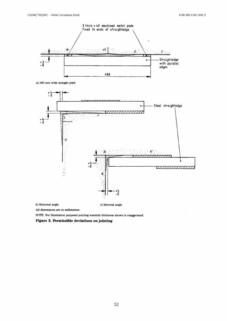
CED4(7782)WC – Wide Circulation Draft FOR BIS USE ONLY
52

CED4(7782)WC – Wide Circulation Draft FOR BIS USE ONLY
53

CED4(7782)WC – Wide Circulation Draft FOR BIS USE ONLY
54
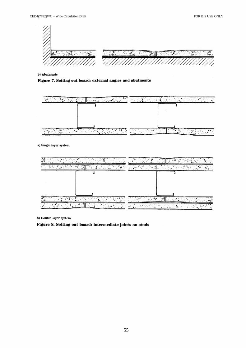
CED4(7782)WC – Wide Circulation Draft FOR BIS USE ONLY
55
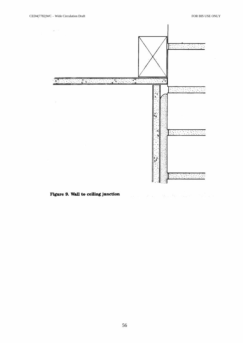
CED4(7782)WC – Wide Circulation Draft FOR BIS USE ONLY
56

CED4(7782)WC – Wide Circulation Draft FOR BIS USE ONLY
57

CED4(7782)WC – Wide Circulation Draft FOR BIS USE ONLY
58
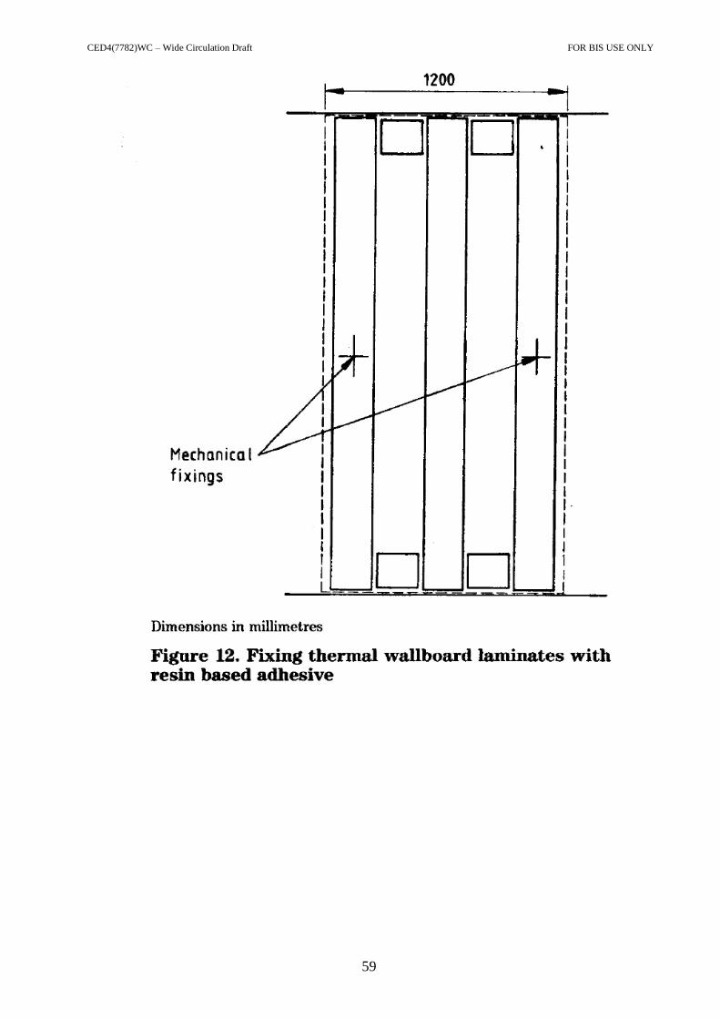
CED4(7782)WC – Wide Circulation Draft FOR BIS USE ONLY
59
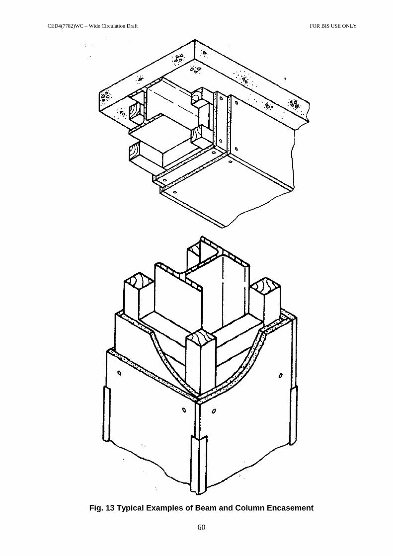
CED4(7782)WC – Wide Circulation Draft FOR BIS USE ONLY
60
Fig. 13 Typical Examples of Beam and Column Encasement

CED4(7782)WC – Wide Circulation Draft FOR BIS USE ONLY
61
a) Common Stud Types
Fig. 14 Typical steel stud partitions

CED4(7782)WC – Wide Circulation Draft FOR BIS USE ONLY
62
b) Typical Vertical Section
Note: Sealants, sole plate and skirting have been omitted. Fig. 14 Typical steel stud partitions

CED4(7782)WC – Wide Circulation Draft FOR BIS USE ONLY
63

CED4(7782)WC – Wide Circulation Draft FOR BIS USE ONLY
64

CED4(7782)WC – Wide Circulation Draft FOR BIS USE ONLY
65

CED4(7782)WC – Wide Circulation Draft FOR BIS USE ONLY
66