Embed Size (px)
Citation preview

IBM Cloud Object Storage System™
Version 3.14.12
Manager Administration Guide
IBM

This edition applies to IBM Cloud Object Storage System™ Version 3.14.12 and is valid until replaced by new editions.© Copyright International Business Machines Corporation 2017, 2020.US Government Users Restricted Rights – Use, duplication or disclosure restricted by GSA ADP Schedule Contract withIBM Corp.
Contents
Document Information.........................................................................................vii
Chapter 1. Overview.............................................................................................. 1Browser compatibility..................................................................................................................................1Manager Web Interface navigation............................................................................................................. 1
Functional tabs....................................................................................................................................... 1System links............................................................................................................................................2Navigation and search............................................................................................................................ 2
Chapter 2. First-time setup.................................................................................... 3Configuring a system....................................................................................................................................3Configuring a new system............................................................................................................................3
Chapter 3. Configuration........................................................................................4System access..............................................................................................................................................4Approve registered devices......................................................................................................................... 4
Approving a single device.......................................................................................................................4Approving multiple devices....................................................................................................................4
Cabinets........................................................................................................................................................6Importing a cabinet configuration......................................................................................................... 6Exporting a cabinet configuration.......................................................................................................... 6Creating a cabinet...................................................................................................................................6Configuring a cabinet with drag-and-drop.............................................................................................6
Access pools................................................................................................................................................ 7Creating an Access Pool......................................................................................................................... 7Editing an Access Pool............................................................................................................................9Editing a Device.................................................................................................................................... 11Moving an Accesser® Node...................................................................................................................11Configuring HTTPS certificates for Access Pools................................................................................ 11Deleting an Access Pool....................................................................................................................... 12
Storage pools............................................................................................................................................. 12Creating a storage pool........................................................................................................................ 12Editing a storage pool...........................................................................................................................14Monitoring storage capacity.................................................................................................................15Adding storage capacity.......................................................................................................................15Expanding a storage pool.....................................................................................................................15Changing the storage pool reallocation rate....................................................................................... 16Pausing a storage pool reallocation.....................................................................................................17Add capacity to an existing storage pool set.......................................................................................17Replacing storage pool sets.................................................................................................................17Removing storage pool sets.................................................................................................................18Merging two storage pools...................................................................................................................18Delete a storage pool........................................................................................................................... 20Replace and evacuate the data from Slicestor devices...................................................................... 20Replacing a Slicestor® Device...............................................................................................................21Pause/resume data evacuation........................................................................................................... 21Terminating data evacuation............................................................................................................... 21Rolling back a data evacuation............................................................................................................ 22Changing the destination device..........................................................................................................22Change the rate of evacuation during evacuation...............................................................................22
iii
Troubleshooting data evacuation incidents........................................................................................ 23Configuring object expiration...............................................................................................................24
Vaults..........................................................................................................................................................25Overview............................................................................................................................................... 26Management vaults.............................................................................................................................. 27Standard vaults.................................................................................................................................... 29Container vaults................................................................................................................................... 30Service vaults....................................................................................................................................... 30Configuring vault protection.................................................................................................................30Configuring SecureSlice algorithm.......................................................................................................31Configuring System Vault Name Index Format................................................................................... 32Creating vaults......................................................................................................................................32Create vaults by using vault templates................................................................................................38Vault proxy settings..............................................................................................................................39Vault security........................................................................................................................................40Tags.......................................................................................................................................................41Vault data migration............................................................................................................................. 42
Vault mirrors.............................................................................................................................................. 43Overview............................................................................................................................................... 43Creating a vault mirror..........................................................................................................................44Creating mirrors by using mirror templates........................................................................................ 46Deploying a vault mirror....................................................................................................................... 47Setting vault mirror permissions..........................................................................................................47Editing a vault mirror............................................................................................................................ 47Breaking a vault mirror.........................................................................................................................48Destroying a vault mirror......................................................................................................................48Monitor a vault mirror...........................................................................................................................49Creating a protected vault mirror.........................................................................................................49Creating protected mirrors by using mirror templates....................................................................... 51Repairing a protected mirror................................................................................................................52
Chapter 4. Security..............................................................................................54Security overview.......................................................................................................................................54Roles...........................................................................................................................................................54Authentication and authorization..............................................................................................................55
Creating an account............................................................................................................................. 55Editing an account................................................................................................................................57Deleting an account..............................................................................................................................59Creating a group................................................................................................................................... 59Editing a group......................................................................................................................................60Deleting a group................................................................................................................................... 61
Granting access key and password authentication.................................................................................. 61Vault deletion authorization...................................................................................................................... 62Organizations............................................................................................................................................. 62
Creating an organization...................................................................................................................... 63Viewing an organization....................................................................................................................... 63Editing an organization.........................................................................................................................63Deleting an organization...................................................................................................................... 64
Chapter 5. Administration....................................................................................65Overview.....................................................................................................................................................65Backing up and restoring the Manager..................................................................................................... 65
Configure Manager backups................................................................................................................ 65Setting the retention policy..................................................................................................................65Set backup configuration parameters................................................................................................. 66Back up to a local directory..................................................................................................................66Backing up to a secure file transfer protocol.......................................................................................66
iv
Backing up the Manager manually.......................................................................................................67Restoring Manager data....................................................................................................................... 68Monitor the Manager backup progress................................................................................................68Retrieving a Manager backup from a remote server........................................................................... 69
Configuring SMTP.......................................................................................................................................69Configuring Call Home............................................................................................................................... 70Configure alerts..........................................................................................................................................71
Configuring email alert rules................................................................................................................71Configuring alert forwarding................................................................................................................ 71SNMP trap details.................................................................................................................................72
Suppressing device events........................................................................................................................ 73Configure active directory / LDAP..............................................................................................................73Configuring keystone authentication........................................................................................................ 75Configure provisioning API........................................................................................................................ 76Configuring certificate authority................................................................................................................76
Adding a certificate authority...............................................................................................................76Edit a certificate authority....................................................................................................................77Generate new internal certificate authority........................................................................................ 77Delete a certificate authority............................................................................................................... 78Revoke a certificate authority.............................................................................................................. 78Supply external certificates to IBM Cloud Object Storage System™ devices..................................... 79
Configure Network Transport Layer ......................................................................................................... 80Configure drive health................................................................................................................................81Configure maximum Accesser devices offline.......................................................................................... 81Edit default maximum Accesser devices offline.......................................................................................82Edit maximum Accesser devices offline................................................................................................... 82Configure system owner............................................................................................................................83Configure SNMP......................................................................................................................................... 83Configure Device Level API........................................................................................................................84Configure preferences............................................................................................................................... 84Configure custom login banner................................................................................................................. 84Configuring system properties.................................................................................................................. 85
Enabling Cross Site Request Forgery protection.................................................................................86Configure advanced system settings........................................................................................................ 87Configuring SSH keys.................................................................................................................................88Configuring notifications for the Notification Service............................................................................... 88
Editing or disabling a Notification Service........................................................................................... 89Deleting a Notification Service.............................................................................................................90
Configure extended COS API.....................................................................................................................90Configure Resource Configuration API................................................................................................ 90
Configuring Optimistic Status Reporting...................................................................................................91
Chapter 6. Monitoring the system.........................................................................92Monitored components............................................................................................................................. 92Device health summary............................................................................................................................. 92
Monitor device health...........................................................................................................................93Monitor storage pool health.................................................................................................................94Monitor vault health............................................................................................................................. 95Monitor site health............................................................................................................................... 95
Monitor drive states................................................................................................................................... 96Drive lifecycle states............................................................................................................................ 96Drive summary and bulk resume......................................................................................................... 98
Drive lifecycle state descriptions and troubleshooting............................................................................ 99ONLINE................................................................................................................................................. 99INIT.......................................................................................................................................................99OFFLINE................................................................................................................................................99DIAGNOSTIC........................................................................................................................................ 99
v
MIGRATING........................................................................................................................................102UNUSABLE..........................................................................................................................................103FOREIGN............................................................................................................................................ 103UNKNOWN..........................................................................................................................................104
RAID states.............................................................................................................................................. 104Event console...........................................................................................................................................104
Open incidents................................................................................................................................... 104Events................................................................................................................................................. 105Event search.......................................................................................................................................105Audit search....................................................................................................................................... 107Export................................................................................................................................................. 107Performance graphs...........................................................................................................................108Annotated graphs...............................................................................................................................116
Disabling events on a device................................................................................................................... 116Device summary...................................................................................................................................... 117
Filtering devices by using tabs...........................................................................................................117Filtering devices by using extra filters...............................................................................................117Apply filters to device list results...................................................................................................... 118
Chapter 7. Maintenance..................................................................................... 119Overview.................................................................................................................................................. 119Upgrade....................................................................................................................................................119
Upgrade settings configuration......................................................................................................... 124Constraints to upgrades.....................................................................................................................124Migrating devices to IPv6...................................................................................................................125
IBM Cloud Object Storage Insight™.........................................................................................................126Configuring IBM Cloud Object Storage Insight™............................................................................... 128Manually starting IBM Cloud Object Storage Insight™ sessions.......................................................129Viewing an anonymized object.......................................................................................................... 129
Logs.......................................................................................................................................................... 129Collecting logs manually.................................................................................................................... 130Collecting logs automatically.............................................................................................................131Redacting client information..............................................................................................................132Collecting log status...........................................................................................................................133Configuring device logs...................................................................................................................... 133
Troubleshooting console.........................................................................................................................134Changing the device local password.......................................................................................................136Automatic report emailing.......................................................................................................................137Reporting................................................................................................................................................. 137
Generating disk drive and device reports..........................................................................................138Generating storage pool capacity and disk report............................................................................ 139Generating a vault usage report........................................................................................................ 141Generating expiration scanning and reclamation for devices report............................................... 141Generating expiration scanning and reclamation for storage pools report..................................... 142Vault summary report........................................................................................................................ 143Reporting device summary................................................................................................................ 144Failed FRU report............................................................................................................................... 144Reporting event information..............................................................................................................145Firmware report................................................................................................................................. 146Redaction status report..................................................................................................................... 146
Post login message..................................................................................................................................147
Notices..............................................................................................................148Trademarks..............................................................................................................................................149Homologation statement.........................................................................................................................150
vi
Document Information
Intended Purpose and Audience
This IBM Cloud Object Storage Manager™ Administration Guide describes how to use the Manager WebInterface to configure, secure, monitor, maintain, and administer the system. The audience is thoseresponsible for data storage administration. This guide applies to both the Manager device and theManager application.
CAUTION: If the devices have been installed and a more recent version of the software isavailable, the devices should be upgraded to the newer version. Contact IBM® Customer Supportfor assistance with upgrades.
© Copyright IBM Corp. 2017, 2020 vii

viii IBM Cloud Object Storage System™ : Manager Administration Guide
Chapter 1. Overview
Browser compatibilityThe Manager Web Interface supports the following browsers:
• Microsoft Internet Explorer® 11 through current• Microsoft Edge®
• Firefox 4.0 through current• Chrome versions through current• Safari versions through current
Attention:
Microsoft ended support of IE9 and IE10 on 1/12/2016. Only the most current Microsoft browserversions will be supported: IE11 and Microsoft Edge, or use the most recent Firefox, Chrome, orSafari browsers. In general, users of older browser versions should upgrade to the most recentversion.
IE browsers require special settings when used for upgrade. See “Upgrade” on page 119 fordetails.
Note: In systems with many vaults, the performance of Chrome on MacOS might be slower than Firefox orSafari on MacOS.
If your browser is not listed, most functions work. Many problems can be resolved by turning on yourbrowser's compatibility function.
Manager Web Interface navigationThe Manager Web Interface is structured to facilitate optimum setup, configuration, monitoring, andadministration of the system.
There are three main components for navigating the Manager Web Interface:
• “Functional tabs” on page 1• “System links” on page 2• “Navigation and search” on page 2
Functional tabsFunctions are organized in tabs: Monitor, Configure, Security, Maintenance, and Administration.
The Manager Web Interface function can be mapped to Information Technology Infrastructure Library(ITIL) and Fault, Configuration, Accounting or Administration, Performance and Security management(FCAPS) processes and workflow:
Table 1. Manager Web Interface function mapping
Monitor Configure Security Administration Maintenance
ITIL Run Build/Plan Manage Manage Build
FCAPS FM/PM CM SM AM CM
© Copyright IBM Corp. 2017, 2020 1
System linksThe upper right corner has icon links for search, help, and account information.
The Help icon opens a drop-down menu that provides links to context-specific Help for this page, thelanding page of the embedded Knowledge Center, and details About this system including ClevOSversion number, system UUID, and the system name.
The Account icon opens a drop-down menu that provides links to your profile and to sign out.
My accountAccount information can be accessed by clicking the account icon in the header and then clicking Profile.
• Click Change to change the name that is displayed on the account, email address, and the time zone.• Click Change Password to change the password for the current account.
Note: The default account, admin, is assigned super user access to all Manager Web Interface functions.It allows the admin account to complete all initial setup without requiring extra accounts.
Help
The Help icon opens a drop-down menu that consists of the following items:
• Help for this page: Links to the help page that is specific to the page you are on when you click the link.• Knowledge Center: Links to the Welcome page of the embedded Knowledge Center, which is the help
system for the IBM Cloud Object Storage System. The embedded Knowledge Center provides a subsetof the full product documentation, which can be found online.
• About this system: Provides system details including ClevOS version number, system UUID, and thesystem name.
When certain functional modes are enabled, the Help also menu includes additional items that arespecific to those modes.
For full product documentation, see the online Knowledge Center.
Navigation and searchIn the Monitor and Configure tabs, the navigation panel on the left side of the Manager Web Interfaceprovides a way to browse and move between the components of the system.
Search functionsAutocomplete and standard search functions are available. When a suggestion is selected, the associatedpage is displayed.
For standard search, click the Search icon in the header. The results are provided on the right.
Autocomplete cannot be used for the following items:
Table 2. Items that cannot be auto-completed.
Page Items
Monitor or Configure • site abbreviation• device IP addresses• device type• device alias• device serial number
Security • account user name• email
Tip: Standard search can be used for these items.
2 IBM Cloud Object Storage System™ : Manager Administration Guide
Chapter 2. First-time setup
Configuring a systemWhen all devices are physically installed and individually configured, further configuration must be doneat the system level.
Before you begin
Open the Manager Web Interface in a web browser, by using https://{Manager_IP} where{Manager_IP} is the IP address that is created during the installation of the Manager device.
When first logging in to the Manager Web Interface, the user needs to accept IBM standard and non-IBMEnd User License Agreements (EULA). The user is needs to complete the Print Name (License Acceptor)field and check the appropriate box and click Accept IBM & non-IBM Licenses to accept the EULA andthen continue to configure the System. Declining the agreement takes the user to the Decline page.
After you accept the EULA, you can create a new system or restore a previous setup.
Procedure
1. Click either Create new or Restore this Manager Web Interface.2. Click the Begin link.
Note: For more information on restoring a previously created system, see “Restoring Manager data”on page 68.
Configuring a new system
Before you begin
Note: If the initial session ends before the setup is complete, the next session will begin at the next step.
Procedure
1. Enter and confirm a new password for the admin user name.2. Click Save and Continue to continue the initial setup process.3. Enter the name of the first site at the prompt.
The default is My Site. More site information can be added but is not required; however, more siteinformation can facilitate hardware replacement.
4. Click + Add Additional Site to add sites.It is possible to create, modify, and delete sites after this step, but one site will be created by default.
Note: If the Slicestor® devices are to be deployed to more than one site, create the sites even if thedevices are initially staged in one location. By defining the sites and assigning Slicestor devices tothose sites, data is written equally across devices and sites. It ensures that the reliability andavailability benefits of using multiple locations are realized.
5. Click Finish to show the Dashboard.
Devices that are completed with physical configuration are shown on here, although it can take a fewminutes for the Manager Web Interface to see the devices to be approved. Continue with configurationtasks here or move to set up more accounts so that other users might potentially take on some or all ofthese tasks.
To return to the Dashboard page, click the logo in the upper left corner of the page.
© Copyright IBM Corp. 2017, 2020 3
Chapter 3. Configuration
System accessAttention: Configuration tasks require an account that has access rights to the Configure page.
Approve registered devicesDevices register themselves with the Manager Web Interface as part of the initial configuration. Beforedevices can be used, they must be approved by using one of the following methods. Devices to beapproved are listed on the Configure page under Devices Pending Approval.
Devices can be approved individually or in bulk. Bulk selection can be achieved by clicking multiple checkboxes or all devices. The workflow is slightly different between the two approval methods. The fingerprintis needed from the initial configuration form to verify the key that is shown as part of the device approval.Go to External CA Device Approval if you defined external CAs for the devices.
Note: During device approval, Slicestor devices can be assigned to sites. If Slicestor devices are to bedeployed to more than one site, create the sites even if the devices are initially staged in one location.Defining the sites and assigning Slicestor devices to those sites ensures that data is written equally acrossdevices and sites. It guarantees that you realize the reliability and availability benefits when usingmultiple locations.
Approving a single device
Procedure
1. From the list of Devices Pending Approval on the bottom of the Configure page, click a single deviceto display the devices information page.
2. Verify that the key fingerprint is correct and click Approve or Deny from the action bar.3. Click Deny to remove the device from the pending list.
• To add the device back to the pending approval list, rerun manager ip {ip-address} (ormanager ip_ipv6 {ip-address}), where {ip-address} is the IP address from the denieddevice.
• A single device approval gives the option to add the device to an existing site or create a new siteand set an optional alias.
4. Verify that the devices are added on the Summary section under the Devices tab and that the devicesummary count is updated accurately.
Approving multiple devicesDevices must be approved by the manager before they are added to the system.
Before you begin
Attention: Any time a device is added or a vault, site, cabinet, or an administration configuration ischanged, the Manager device must be backed up by using the Backup and Restore utility.Permanent data loss can occur if the Manager database becomes corrupted. Periodic backupsmust also be performed to preserve historical statistics and log information. See Backup settingson the Administration menu.
4 IBM Cloud Object Storage System™ : Manager Administration Guide
Procedure
1. Any user who wants their devices to be on file for engine type or storage format must select File fromthe Engine Storage drop-down. This step must be done first before they can select their devices.
Note: This step should only be done when someone wants to override the system default enginepacked.
2. Click the check boxes next to the device Hostname column to approve that device, from the list ofDevices Pending Approval on the bottom of the Configure page.
3. Click Bulk Approve/Deny.After the devices are selected for approval, the device registration screen appears.
4. Review the security key fingerprint information for the devices to ensure that the registration is froma trusted source.For bulk approvals, you can select individual or all devices.
5. Click Approve, Deny, or Cancel from either action bar.After the devices are approved, a menu for site assignment appears.
6. Click Deny to remove the device from the pending list.
If a Device is Denied, the device must be reinitialized from the IBM Appliance Configuration utilitybefore it can be Approved. (For more information, see Configuring appliances).
It is necessary to rerun manager ip {ip-address} (or manager ip_ipv6 {ip-address}),where {ip-address} is the IP address from the denied device.
Note: The only choice is to approve all or deny all. If only a subset of the devices needs approval,click Cancel.
7. Associate devices with sites by checking one or more devices and selecting the site to which theybelong.During bulk operations, the approved devices are displayed at the top of the Bulk Edit Device Sitepage, and a list of sites appear at the bottom.
Note: If multi-node devices need approval, selecting a node automatically selects all other nodes inthe same chassis.
8. Click Save to confirm the mapping of devices to sites.As devices are associated with sites, they are removed from the device list at the top of the page.
9. Continue associating devices with sites until complete.
Multiple devices can be selected by checking the check boxes to the left of each site.
After all bulk devices are assigned to a site, an alias can be set for each device in its adjacent textbox.
10. Verify that the devices are added on the summary section under the devices tab and that the devicesummary count is updated accurately.
11. Click Save.
Setting an alias for each device is optional. For either approval method, the device displays aninactive state until polling is completed. It takes less than 1 minute.
The Bulk Edit Device Alias page is shown.
Chapter 3. Configuration 5
Cabinets
Importing a cabinet configurationThe Cabinet application can be used to group the devices by cabinets to facilitate maintenance andinventory tracking operations.
About this task
The configuration of devices within cabinets can be imported from a cabinet configuration .csv (comma-separated values) file. The file format can be found in the Manager Reference Guide.
Procedure
1. Log in to the Manager Web Interface with your user name and password.2. Click Configure tab.3. Click Import in the Import/Export Configure Cabinet Description File bar.4. Select the file.5. Enter your password.6. Click Import to import the configuration.
Attention: Importing a file deletes the current configuration and cannot be reversed. Export thecurrent configuration as a backup before you import the new file.
Exporting a cabinet configurationThe configuration of devices within cabinets can be exported as a .csv file.
Procedure
1. Log in to the Manager Web Interface with your user name and password.2. Click the Configure tab.3. Click Export in the Import/Export Cabinet Description File Configure Cabinet action bar.4. Save the .csv file to a location on your computer.
Creating a cabinetUse this procedure as an alternative to importing a cabinet.
Procedure
1. Log in to the Manager Web Interface with your user name and password.2. Click the Configure tab.3. Click the Create Cabinet link in the Summary section.4. Enter the information in the form.5. Click Save to complete the creation of the new cabinet.
Configuring a cabinet with drag-and-dropAs an alternative to editing and importing the cabinet configuration file, the configuration of deviceswithin cabinets can also be modified by dragging devices into and out of the cabinet on the Edit Cabinetpage.
About this taskIn the cabinet view, as part of a multi-node Slicestor device configuration (see “Approve registereddevices” on page 4), all nodes that belong to the same chassis are presented together. In the UI, a single4U instance appears that can be placed in the cabinet.
6 IBM Cloud Object Storage System™ : Manager Administration Guide

Note: Virtual appliances can't be added to a cabinet and do not appear in the Devices Not In Cabinetcolumn.
Procedure
1. Log in to the Manager Web Interface with your user name and password.2. Click the Configure tab.3. Click Sites in the navigation panel.4. In the Site Summary section, select the name of a site.5. In the Cabinets section, Click the name of the cabinet you want to configure.6. In the Edit Cabinet page, click Change in the action bar.7. Drag a device from the Devices Not In Cabinet column into a slot in the Cabinet column to add it to a
cabinet.8. Drag a device out of the Cabinet column to remove it from that cabinet.9. Add generic devices by clicking Add Generic Device and edit the description in place by clicking the
text.10. Click Update to save the configuration changes.
Access poolsAn access pool is a logical set of zero or more Accesser® nodes.
Access pools can be assigned the same set of attributes, such as programming interface and accessservice port numbers, in aggregate instead of per device. An access pool can be deployed to a selection ofvaults and vault mirrors in a system. An access pool can be removed from the system, but affects alldeployed vaults and mirrors. A password prompt is required since delete Is a non-recoverable action.However, it is possible to re-create and re-deploy the access pool if deleted.
Creating an Access PoolThese steps allow you to set a management vault at the access pool level.
Procedure
1. Navigate to Monitor > System2. Click the Create Access Pool link under the Summary heading to display the Create New Access Pool
page.3. If changes to the Access Pool are needed:
a) Enter a name for the new Access Pool in the Name field.
Note: The maximum length of the Name field is 255 characters.b) Enter a description for the new Access Pool in the Description field.c) From the API Type drop-down menu, select the wanted programming interface:
• Cloud Storage Object• Simple Object• OpenStack Object Storage
Note: When the system is in container mode, the Simple Object API Type, Protected Vaults, andProtected Objects are not supported.
Note: Operations on Protected Vaults and Protected Objects are only supported via Cloud ObjectStorage.
If you plan to deploy this access pool to a protected vault, the Simple Object and OpenStack ObjectAPI Types are not supported.
Chapter 3. Configuration 7
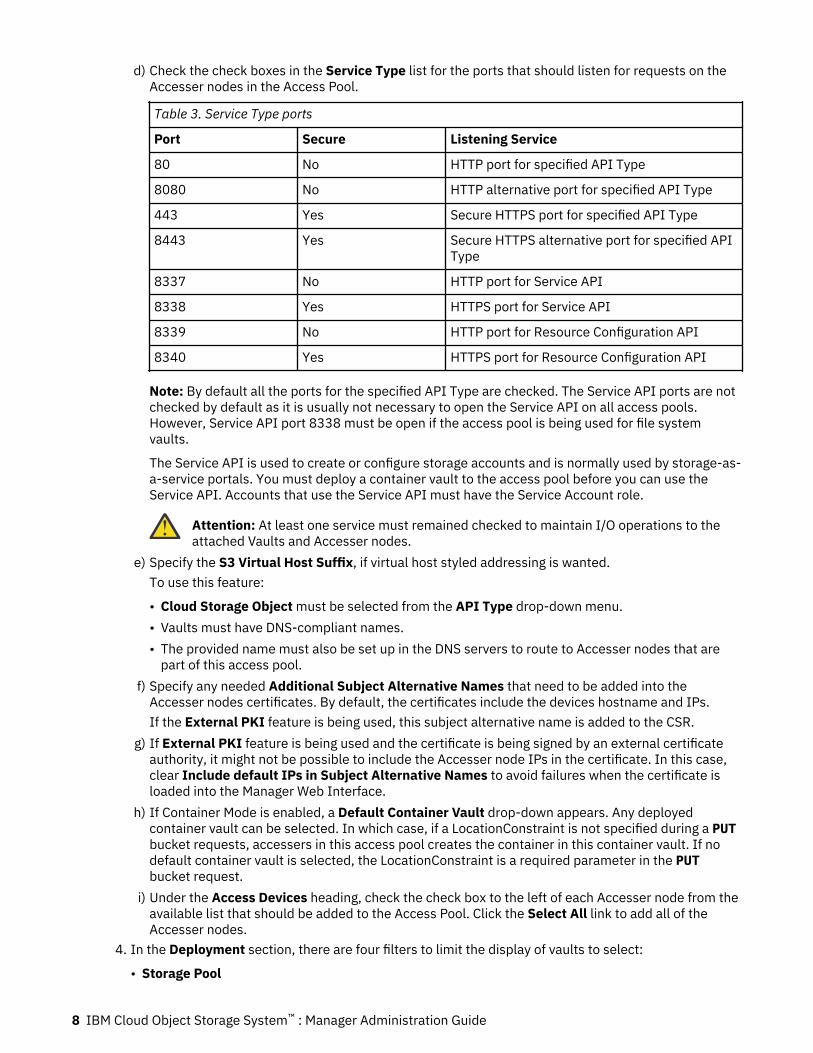
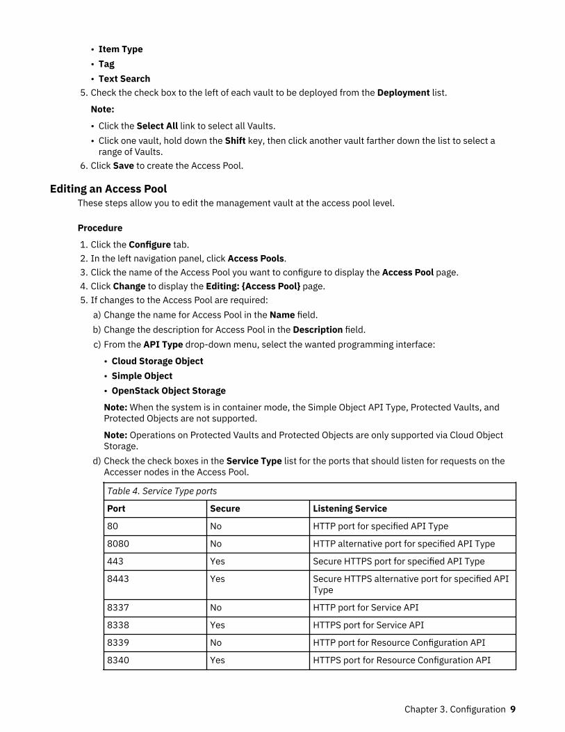
d) Check the check boxes in the Service Type list for the ports that should listen for requests on theAccesser nodes in the Access Pool.
Table 3. Service Type ports
Port Secure Listening Service
80 No HTTP port for specified API Type
8080 No HTTP alternative port for specified API Type
443 Yes Secure HTTPS port for specified API Type
8443 Yes Secure HTTPS alternative port for specified APIType
8337 No HTTP port for Service API
8338 Yes HTTPS port for Service API
8339 No HTTP port for Resource Configuration API
8340 Yes HTTPS port for Resource Configuration API
Note: By default all the ports for the specified API Type are checked. The Service API ports are notchecked by default as it is usually not necessary to open the Service API on all access pools.However, Service API port 8338 must be open if the access pool is being used for file systemvaults.
The Service API is used to create or configure storage accounts and is normally used by storage-as-a-service portals. You must deploy a container vault to the access pool before you can use theService API. Accounts that use the Service API must have the Service Account role.
Attention: At least one service must remained checked to maintain I/O operations to theattached Vaults and Accesser nodes.
e) Specify the S3 Virtual Host Suffix, if virtual host styled addressing is wanted.To use this feature:
• Cloud Storage Object must be selected from the API Type drop-down menu.• Vaults must have DNS-compliant names.• The provided name must also be set up in the DNS servers to route to Accesser nodes that are
part of this access pool.f) Specify any needed Additional Subject Alternative Names that need to be added into the
Accesser nodes certificates. By default, the certificates include the devices hostname and IPs.If the External PKI feature is being used, this subject alternative name is added to the CSR.
g) If External PKI feature is being used and the certificate is being signed by an external certificateauthority, it might not be possible to include the Accesser node IPs in the certificate. In this case,clear Include default IPs in Subject Alternative Names to avoid failures when the certificate isloaded into the Manager Web Interface.
h) If Container Mode is enabled, a Default Container Vault drop-down appears. Any deployedcontainer vault can be selected. In which case, if a LocationConstraint is not specified during a PUTbucket requests, accessers in this access pool creates the container in this container vault. If nodefault container vault is selected, the LocationConstraint is a required parameter in the PUTbucket request.
i) Under the Access Devices heading, check the check box to the left of each Accesser node from theavailable list that should be added to the Access Pool. Click the Select All link to add all of theAccesser nodes.
4. In the Deployment section, there are four filters to limit the display of vaults to select:
• Storage Pool
8 IBM Cloud Object Storage System™ : Manager Administration Guide
• Item Type• Tag• Text Search
5. Check the check box to the left of each vault to be deployed from the Deployment list.
Note:
• Click the Select All link to select all Vaults.• Click one vault, hold down the Shift key, then click another vault farther down the list to select a
range of Vaults.6. Click Save to create the Access Pool.
Editing an Access PoolThese steps allow you to edit the management vault at the access pool level.
Procedure
1. Click the Configure tab.2. In the left navigation panel, click Access Pools.3. Click the name of the Access Pool you want to configure to display the Access Pool page.4. Click Change to display the Editing: {Access Pool} page.5. If changes to the Access Pool are required:
a) Change the name for Access Pool in the Name field.b) Change the description for Access Pool in the Description field.c) From the API Type drop-down menu, select the wanted programming interface:
• Cloud Storage Object• Simple Object• OpenStack Object Storage
Note: When the system is in container mode, the Simple Object API Type, Protected Vaults, andProtected Objects are not supported.
Note: Operations on Protected Vaults and Protected Objects are only supported via Cloud ObjectStorage.
d) Check the check boxes in the Service Type list for the ports that should listen for requests on theAccesser nodes in the Access Pool.
Table 4. Service Type ports
Port Secure Listening Service
80 No HTTP port for specified API Type
8080 No HTTP alternative port for specified API Type
443 Yes Secure HTTPS port for specified API Type
8443 Yes Secure HTTPS alternative port for specified APIType
8337 No HTTP port for Service API
8338 Yes HTTPS port for Service API
8339 No HTTP port for Resource Configuration API
8340 Yes HTTPS port for Resource Configuration API
Chapter 3. Configuration 9
Note: By default all the ports for the specified API Type are checked. The Service API ports are notchecked by default as it is usually not necessary to open the Service API on all access pools.However, Service API port 8338 must be open if the access pool is being used for file systemvaults.
The Service API is used to create or configure storage accounts and is normally used by storage-as-a-service portals. You must deploy a container vault to the access pool before you can use theService API. Accounts that use the Service API must have the Service Account role.
Attention: At least one service must remained checked to maintain I/O operations to theattached Vaults and Accesser nodes.
e) Specify the S3 Virtual Host Suffix if virtual host styled addressing is wanted. To use this feature:
• Cloud Storage Object must be selected from the API Type drop-down menu.• Vaults must have DNS-compliant names.• The provided name must also be set up in the DNS servers to route to Accesser nodes that are
part of this access pool.f) Specify any required Additional Subject Alternative Names, which need to be added into the
Accesser nodes certificates.By default, the certificates include the devices host name and IPs. If the External PKI feature isbeing used, this subject alternative name is added to the CSR.
g) If External PKI feature is being used and the certificate is being signed by an external certificateauthority, it might not be possible to include the Accesser node IPs in the certificate. In this case,clear Include default IPs in Subject Alternative Names to avoid failures when the certificate isloaded into the Manager Web Interface.
h) If container mode is enabled, a Default Container Vault drop-down appears. Any deployedcontainer vault can be selected. In which case, if a LocationConstraint is not specified during a PUTbucket request, Accessers in this access pool creates the container in this container vault. If nodefault container vault is selected, the LocationConstraint is a required parameter in the PUTbucket request.
i) Under the Access Devices heading, check the check box to the left of each Accesser node from theavailable list that should be added to the Access Pool.
Click the Select All link to add all of the Accesser nodes.j) In the Deployment section, there are four filters to limit the display of vaults to select:
• Storage Pool• Item Type• Tag• Text Search
6. Check or clear the check box to the left of each vault to be deployed or removed from the Deploymentlist.
Note:
• Click the Select All link to select all Vaults.• Click a vault, hold down the Shift key, then click another vault farther down the list to select a
range of Vaults.7. If Detailed System Advanced Configuration has been enabled in the Administration > System
Advanced Configuration page, an Advanced Configuration Options box is displayed.
CAUTION: Contact IBM Support to set Advanced Configuration Options.
8. The Submit Confirmation dialog box displays if:
• Accesser nodes were added or removed.
10 IBM Cloud Object Storage System™ : Manager Administration Guide
• Vaults or Vault Mirrors were added or removed.
The dialog box shows the count of vaults and mirrors that are deployed or removed.
Editing a Device
About this task
Note: Devices in storage pools cannot alter their management vault.
Procedure
1. Click the Configure tab.2. Click Devices > Accessers in the navigation panel.3. Click the link of any Accesser node to display the Accesser: {device-name} page.4. Click Change on the Configure Device page to display the Editing: {Device} page.5. If changes to the node are required:
a) Change the alias for the Accesser node in the Alias field.b) Change the description for the Accesser node in the Description field.c) Select a different Access Pool from the Access Pool drop-down menu to change the Access Pool of
the Accesser node.
Note: The drop-down menu shows the current Access Pool to which the Accesser node belongs, orNo Access Pool if the device is not in any Access Pool.
The drop-down menu is available for an Accesser node only.6. Choose an action to create the new Access Pool:
• Click Update to finalize the changes to the Accesser node.• Click Cancel to cancel any changes to the Accesser node.
Moving an Accesser® NodeAccess Pool devices can be moved to a different Access Pool.
Before you begin
Note: Moving an Access Pool affects vault and mirror deployments.
Procedure
1. Click Configure.2. Click Access Pools in the navigation panel.3. Click the link of an Access Pool to display the Access Pool: {access-pool-name} page.4. Click Move Device to display the Access Devlice Selection to Move from Access Pool: {access-pool-
name} page.5. Click the check box to the left of the Accesser® Nodes to move.6. Click the radio button of the destination Access Pool to which the Accesser® Nodes are to be moved to.7. Click Submit to move the Accesser® Nodes.
Configuring HTTPS certificates for Access PoolsYou can use certificates for HTTPS access that are trusted inside your organization instead of the defaultManager signed certificates.
Procedure
1. Click the Configure tab.
Chapter 3. Configuration 11
2. Click Access Pools in the navigation panel.3. Click the link of an Access Pool to display the Access Pool: {access-pool-name} page.4. In the Access Pool HTTPS Certificate section, click Configure to display the Editing Access Pool
HTTPS Certificate page.5. Paste PEM-formatted private key and certificate text into the corresponding Private Key PEM and
Certificate PEM fields.
• To add more certificates, paste one after another.• To remove a single certificate, delete on the text for that certificate.• To remove all certificates, delete all contents.
6. Click Update to update the certificates for the Access Pool.
Deleting an Access Pool
Procedure
1. Click the Configure tab.2. In the left navigation panel, click Access Pools.3. Click the name of an Access Pool to display the Access Pool: {access-pool-name} page.4. Click Delete Access Pool to display the Delete Access Pool page with the count of vaults that are to
be deleted.5. Enter your password in the Password field.6. Click Delete to delete the Access Pool.
Note: The selected Access Pools are immediately deleted. No confirmation dialog displays whenDelete is clicked.
Storage poolsA storage pool is defined by a logical grouping of Slicestor devices that are used to store vault data.
A vault is created on a storage pool. These are a few rules to keep in mind:
• Storage pools must be defined before vault creation. If pools are not defined, vault creation isredirected to the Create Storage Pool page.
• Multiple vaults can be created on a storage pool.• A Slicestor device can be a member of a single storage pool. A Slicestor device can be replaced and the
data is evacuated to another device. Network throughput that is allocated for this operation can becontrolled via a data evacuation rate limit parameter.
• Storage Pools can be created with packed storage enabled. Packed storage improves small objectperformance.
Note: Packed storage can be enabled when all devices are upgraded to ClevOS 3.4.0.• If at least one Notification Service exists, the Notification Service is displayed.• The Object Expiration section is used to configure object expiration settings and view reports.
Creating a storage poolA storage pool is defined by a logical grouping of (Slicestor) devices used to store vault data. A vault isinitially created on a storage pool, and can be expanded by either using an existing storage pool or bycreating a new one.
Before you begin
Note: A Slicestor device can only be assigned to one storage pool. Likewise, a new storage pool can onlybe created from unassigned devices. Once created, a storage pool cannot be expanded, but additionalpools can be created and merged to expand a vault.
12 IBM Cloud Object Storage System™ : Manager Administration Guide

When creating a storage pool, consider the following items:
• Slicestor devices can be selected from any number of sites.• Each pool width (for a given vault) must be a multiple of the vault width.• Devices in the pool can be mixed with different model types with different capacities.• Each device can only be allocated to a single pool.• A minimum number of three Slicestor devices is required to create a storage pool.• The smallest drive count must be at least half of the largest drive count. If necessary, you can modify
this constraint through advanced configuration by contacting IBM Customer Support.• When choosing a Vault Name Index format please consider the work loads associated with the index
format.
When creating a storage pool using Concentrated Dispersal, the following additional items apply:
• Each pool must have a minimum of three devices and a maximum of seven devices (3 devices <=storage pool width <= 7 devices).
• The vault width is a restricted multiple of the pool width (for a given vault). Example: Storage pools withthree devices can have vault widths of 18 and 36.
• All devices in a pool must have the same number of drives.
Procedure
1. In the Monitor or Configure tab, click System in the left navigation panel.2. In the Summary section, click Create Storage Pool.
Storage pools can have different capacity nodes. A model group, consisting of nodes that can beincluded in the same storage pool, must be selected. If nodes across multiple sites are available, therequired site must be selected.
Note: If a storage pool has nodes that span multiple sites, it is recommended that the nodes bebalanced across the sites. Not balancing the nodes can introduce read or write availability issues if asingle site outage occurs.
3. Type a name for this storage pool in the Name field.4. Select an IDA width for this storage pool from the Width drop-down box.
To use Concentrated Dispersal vaults in this pool, select a small width of 3 - 9 Slicestor® Devices.5. Optionally, configure a different Vault Index Version at an individual storage pool and override
the global system setting for Default Vault Index Version using either the New Create Storage Poolpage or the Edit: StoragePoolName page. You can chose one of three options.
a. System Default: If selected, Vault Index Format would be inherited from the System Level Setting.For more details see “Configuring System Vault Name Index Format” on page 32
b. Version 4: Required for all data management features. This provides significantly improved listingperformance with a reduce small object write performance.
c. Version 2: Must not be used for data management features. This provides a better small objectwrite performance over version 4, but significantly lowers S3 listing performance.
Note: For more information on Use Cases and Workflow see “Selecting Vault Name Index Format” onpage 32
6. Check the Packed Storage check box to enable packed slice storage for this storage pool.
CAUTION: Packed storage can be enabled when all Slicestor nodes are upgraded to ClevOS 3.4or newer.
Note: Ask IBM support if enabling packed slice storage benefits current storage needs.7. Select the Slicestor devices to add to this pool.
Chapter 3. Configuration 13

a) If you know the devices you want to add, filter devices by storage engine, model group, or site, thenselect the Slicestor devices for the new device set.
Note: Available filters can vary based on system configuration.b) If you don't know the devices you want to add, click Suggest Devices to allow the Manager
application to select Slicestor devices on your behalf.8. Select devices either automatically using Suggest Devices per the above rules, or manually. Suggest
Devices selects the width number of devices by using the selected check boxes that list devices bydrive count. More than one drive count check box can be selected.
Note: If you reimaged a Slicestor appliance for use in a storage pool, the device might not be availablefor use immediately after approval. The Slicestor appliance can be used when the device startspublishing a valid "Storage Engine" and "Total Size" to the Manager
9. Click Save to create the Storage Pool.
What to do next
Attention:
If there is not an even distribution of Slicestor devices across the available sites where the loss ofone site would make Vaults either unusable or read-only, the Manager Web Interface displays aconfirmation dialog box that asks the operator if they accept the settings with the risks theypresent:
The selected devices are not balanced evenly across sites. This could lead to read and write availability issues in the case of a site outage. Do you still wish to continue?
The operator can click Cancel or OK to change or keep the settings.
From the Configure Storage Pool page, click Change to rename this storage pool or Monitor to shortcutto the monitor function for this storage pool. A different storage pool can be selected from the storagepool landing page.
Editing a storage poolAllows you to edit the management vault at the storage pool level.
About this taskConfiguring HTTPS certificates for Storage Pools
Note: The Embedded Accesser service needs to be enabled.
You can use certificates for HTTPS access that are trusted inside your organization instead of the defaultManager signed certificates.
Procedure
1. Click the Configure tab.2. Click Storage Pools in the navigation panel.3. Click the link of a Storage Pool to display the Storage Pool: {storage-pool-name} page.4. In the HTTPS Certificate Chain section, click Configure to display the Editing HTTPS Certificate
Chain: {storage-pool-name} page.5. Paste PEM-formatted private key and certificate text into the corresponding Private Key PEM and
Certificate PEM fields.
• To add more certificates, paste one after another.• To remove a single certificate, delete the text for that certificate.• To remove all certificates, delete all contents.
6. Click Update to update the certificates for the Storage Pool.
14 IBM Cloud Object Storage System™ : Manager Administration Guide

Monitoring storage capacityCapacity is reported after Slicestor® Devices are approved.
Allocated, unallocated, and rawreclaimable capacity can be found in three locations:
Table 5. Capacity locations
Page Description
Monitor Overall and individual capacity
Configure Summary of overall unallocated, rawreclaimable,and allocated capacity
Dashboard Summary of overall unallocated, rawreclaimable,and allocated capacity
In the Monitor tab, when you select a Vault, Raw and Usable used space and free space are shown. Rawspace is a precise calculation. Usable space is an estimate because actual usage depends on the size ofthe files stored. Estimates are indicated by ~. Vault Capacity view is selected by default instead of StoragePool Capacity. You can toggle to the Storage Pool Capacity view to display Other Used, which consists ofspace that is taken by other vaults and incompressible overhead size.
Note: Vault capacity is impacted if a Slicestor® Device is down.
In situations where data is missing, for example, due to replacement of failed drives, vault and storagepool capacity reporting anomalies might arise. The value that is being reported on the Manager WebInterface can give the impression that more space is available for writing data than exists. When thestorage pool is full, attempts to write new objects fail. After rebuilding completes for the data on thesedrives, the values that are reported are correct.
When drives are quarantined in a Slicestor® Device, the allocated and unallocated numbers that areassociated with the Device Capacity section in the Monitor Device page of the Manager Web Interfaceare temporarily inaccurate. Within a few minutes, the correct values are displayed.
Adding storage capacityStorage capacity can be expanded in three ways.
Procedure
Add a storage pool that consists of a fresh collection of devices.
• “Expanding a storage pool” on page 15• “Merging two storage pools” on page 18
CAUTION: In some cases, it is best to add a storage pool instead of merging storage pools, dueto restrictions on vault creation.
What to do next
Note: Contact IBM Customer Support for any questions about merge storage pool usage and limitations.
Expanding a storage poolFollow these steps to expand a Storage Pool.
Before you begin
Before you expand a Storage Pool, the following preconditions must be met:
1. Upgrade all Accesser nodes and Slicestor nodes to release 3.6.0 or later.
Chapter 3. Configuration 15
2. Approve a number of Slicestor nodes equal to a multiple of the least common multiple of all the vaultIDA widths for the vaults that use the Storage Pool to be expanded. If you are using ConcentratedDispersal, you can expand by using either the Concentrated Dispersal set size or an integer multiple ofthe full IDA Width.
Note: If you reimaged a Slicestor appliance to expand a storage pool, the device might not be availablefor use immediately after approval. The Slicestor appliance can be used when the device starts publishinga valid "Storage Engine" and "Total Size" to the Manager.
Procedure
1. In the Configure tab, click Storage Pools in the left navigation panel.2. Click the Storage Pool to replace a device. The Storage Pool: <Pool Name> page displays.3. In the Slicestor Devices section, click Change Sets and Devices.4. In the Expand Storage Pool section, click Configure Storage Pool Expansion.5. From the Width drop-down menu under the General bar, select the IDA Width for the expanded
Storage Pool.6. Select the Slicestor devices to be used to expand this pool.
These devices are used to form a new Device Set within this Storage Pool.a) If you know the devices you want to add, filter devices by storage engine, model, or site, then
select the Slicestor devices for the new device set in one of the following ways:.
Note: Available filters can vary based on system configuration.
• Drive count, by using the check boxes to filter Slicestor devices by number of drives configured.• Sites, by using the check boxes for one or more Sites.• Individual devices, by selecting the check boxes in the Devices section.
b) If you don't know the devices you want to add, click Suggest Devices to allow the Managerapplication to select Slicestor devices on your behalf.
7. Click Continue.A confirmation page appears.
8. Click Save to save your changes.9. Monitor the progress of the reallocation and ensure it continues to completion.
10. Change the Storage Pool Reallocation Rate.
Changing the storage pool reallocation rateStorage Pool expansion can be throttled.
Procedure
1. Click the Storage Pool from the Monitor tab.2. Click Change under the Data Reallocation in Progress window.
The Edit Data Reallocation dialog box displays.3. For all device sets:
a) Check the Enable check box in the Bulk Change section.b) Type a transfer limit in MB per second in the MB/s field.
4. For one device set:a) Check the Per-Device Rate Limiting check box for that Device Set.b) Type a transfer limit in MB per second in the MB/s field.
5. Click Submit to accept these changes.
16 IBM Cloud Object Storage System™ : Manager Administration Guide
Pausing a storage pool reallocationA Storage Pool expansion can be paused.
Procedure
1. Click the Storage Pool from the Monitor tab.2. Click Change on the Data Reallocation in Progress window.
The Edit Data Reallocation dialog box displays.3. To pause a reallocation:
a) For all device sets, check the Pause check box in the Bulk Change section and click Apply to AllSets.
b) For one device set, check the Pause check box for that Device Set.4. Click Submit to accept these changes.
Note: When a Device Set's reallocation is paused, it appears with a -Paused- indicator next to theDevice Sets name.
Add capacity to an existing storage pool setHow to add capacity to an existing storage pool set.
About this task
You can add capacity to an existing partially populated storage pool to take advantage of extra capacity.
Procedure: Add capacity by fully populating Slicestors in the only existing set
1. Install more drives in each Slicestor® Node in the storage pool.2. Once all drives are installed, the storage pool begins using the new capacity
Procedure: Add capacity by fully populating Slicestors in one of the sets that has partially populatedSlicestors.
1. Install more drives in each Slicestor® Node in the storage pool.2. When most of the devices have the additional capacity, click the Configure tab.3. In the navigation panel, click Storage Pools and then select the storage pool that you want to resize.
The Configure Storage Pool page displays a notification that the system identified more capacity.4. When you finish installing extra drives, click Done Adding Capacity in the notification. The notification
displays the estimated capacity before resize and the project capacity after resize.5. Confirm the capacity values and click Approve & Start Data Reallocation. The resize process begins.6. Monitor the add capacity process on the Monitor Storage Pool page.
Replacing storage pool setsHow to replace storage pool sets.
Before you beginBefore you replace Storage Pool sets, you must perform the following preconditions:
1. Upgrade all Accesser® Nodes and Slicestor® Nodes to ClevOS 3.10.0 or newer.2. Approve an amount of Slicestor® Nodes equal to a multiple of the least common multiple of all the
vault IDA widths for the vaults that use the Storage Pool that you want to replace. If you are usingConcentrated Dispersal, you can replace sets by using either the Concentrated Dispersal set size or aninteger multiple of the full IDA Width.
To replace one or more Storage Pool sets:
Chapter 3. Configuration 17
Procedure
1. In the Configure tab, click the Storage Pool you want to replace.2. In the Slicestor Devices section, click Change Sets and Devices.3. Click Configure Set Replacement.4. In the Sets to Replace section, select the Storage Pool sets you want to replace.5. Select the Slicestor® Nodes you want to use to replace the Storage Pool sets.
The devices are used to form a new Device Set within this Storage Pool.6. Select the Slicestor® Nodes you want to add for the new Device Set in one of the following ways:
• Select the check boxes for choosing Slicestor models with similar drive counts• Check the check boxes for one or more Sites to add nodes by Site.• Check the check boxes in the Devices section to add individual nodes.• Click Suggest Devices to allow the Manager application to select Slicestor® Nodes on your behalf.
7. Click Continue.A confirmation page appears.
8. Click Save.9. Monitor the progress of the reallocation and ensure it continues to completion.
Removing storage pool setsTo remove one or more Storage Pool sets, follow these instructions.
Before you begin
Note: To resize a storage pool set, the storage pool must contain multiple sets.
Before you can remove Storage Pool sets, you must upgrade all Accesser® Nodes and Slicestor® Nodes torelease 3.10.0 or newer.
Procedure
1. In the Configure tab, click the Storage Pool that you want to replace.2. In the Slicestor Devices section, click Change Sets and Devices.3. Click Configure Set Removal.4. Select the Storage Pool sets you want to remove and click Continue.
A confirmation page appears.5. To remove the Storage Pool sets, click Save.6. Monitor the progress of the reallocation and ensure it continues to completion.
Merging two storage poolsThe Merge Storage Pool method expands capacity by "combining" a used storage pool with either a newstorage pool or an existing, less used storage pool.
Before you begin
Attention: This method does not work in ClevOS 3.8.0 or newer unless the Storage Pool wasmerged in a previous version.
CAUTION: Consider the following issues when you merge storage pools:
• Only two storage pools can be merged at a time.• Storage pools can be merged regardless of the Slicestor device models that are used in the
pools.
18 IBM Cloud Object Storage System™ : Manager Administration Guide

• After the storage pools are merged, the new pool capacity is the sum of the capacities that areassociated with the original storage pools.
• All vaults that are associated with the original storage pools now become visible to the newmerged storage pool.
• Storage pools of any size can be merged when no vaults exist on either pool. However, after thestorage pools are merged, only vaults that are a divisor of both the storage pool widths can becreated. It is advantageous in many circumstances, but exceptions exist.
For instance, Pool1 (Width = 8) and Pool2 (Width = 9), where both Pool1 and Pool2 do not haveany vaults. After the pools are merged, a user can create vaults of size 1.
• Storage pools of the same width can be merged irrespective of the number and size of vaults oneither pool.
• If the storage pool widths are different and vaults exist, the width of each pool must be an exactmultiple of the width of all the vaults that exist on either pool. This scenario allows larger orsmaller capacity storage pools to be merged.
Given Pool1 (Width = 8) with vault11 (Width = 8) and vault 12 (Width = 4) and Pool2 (Width =16) with vault21 (Width = 8), Pool1and Pool2 can be merged.
• Some storage pools cannot be merged.
Given Pool1 (Width = 8) with vault1 (Width = 8) and Pool2 (Width = 16) with vault2 (Width =16), Pool1 and Pool2 cannot be merged since vault2 cannot be associated with Pool1 after themerge. Such options are not presented on the Merge Storage Pool page in the Manager WebInterface.
Follow these steps when you merge storage pools. Storage pools can be merged in any order.
• Pool_test1 is the original storage pool.• Pool_test2 is either a new storage pool or another storage pool that has lower usage when compared to
Pool_test1.
About this task
With this approach, two storage pools, along with all vaults across these storage pools, are mergedtogether. Only two storage pools can be merged at a time. More storage pools can be merged with thenewly merged storage pool over time as needed. After the pools are merged, the new pool capacity is thesum of the capacity that is associated with the original storage pools. All vaults that are associated withthe original storage pools now become visible to the merged storage pool.
When two storage pools are merged, two sets are formed. Set 1 contains the devices that are associatedwith the first storage pool, and Set 2 contains the devices that are associated with the second storagepool. The set names (Set 1, Set 2) cannot be edited. When a new vault is created, its width must be thesame as a smaller of the two set. Also, when writes are performed to a vault in the merged storage pool,the objective is to fill the storage pools evenly. Thus, writes are adjusted based on the capacity availablewithin individual sets. As an example, if both sets have equal capacity available, writes are ~50/50 acrossthe sets. However, if one set is full and the other is empty, writes are 0/100.
Procedure
1. Log in to the Manager Web Interface through a browser.2. Click Create a Storage Pool on the Configure page.
Note: If an existing storage pool exists for the merge operation, skip this step.
Pool_test2 is a newly created storage pool.3. Go to the Configure page of the original storage pool.4. In the Slicestor Devices section, click Change Sets and Devices.5. In the Merge Storage Pool section, click Configure Storage Pool Merge.
Chapter 3. Configuration 19
6. Select the storage pool to be merged (Pool_test2).All allowable storage pool options are presented.
7. Click Save.Two Sets, Set 1 and Set 2, are created, and each Set corresponds to the devices in the respective,original storage pools.
What to do next
The storage pool name that is retained after the merge depends on the storage pool from which theMerge Storage Pool operation was initiated (Steps 3 and 4).
In this example, Pool_test1 was used. As a result, the name of the new merged storage pool (after Step6) is Pool_test1.
Delete a storage poolA storage pool can be removed from the system if no vaults are attached to this pool. A password promptis needed for this unrecoverable action.
The devices and vaults that are associated with this storage pool are also shown. Click Change in thedevice box to replace a specific device in the storage pool.
Replace and evacuate the data from Slicestor devicesA Slicestor device can be replaced and its data can be evacuated to another device.
The device that is moving out of the storage pool is called the source device, and the device that is movingin to the storage pool is called the destination device. Before a source device is replaced, the followinginternal checks must pass:
• The storage pools that contain the source and destination devices must be updated to ClevOS 3.4.0.0 orlater.
• The destination device must have a capacity equal to or greater than the source device.• The destination device must be reimaged if it previously contained data.
Note: When a Slicestor appliance is reimaged and approved, it takes some time before device isavailable to be used. The Slicestor appliance can be used when the following event is generated inevent console:
Slicestor started for the first time.
• Both the source and destination device must not already be a part of an ongoing device replacement.• The replacement process must not impact vault health.• When evacuating data from more than one device, the storage pool must be healthy. The maximum
number of devices you can evacuate in parallel is equal to the difference between the vault Width andAlert Level, and is also dependent on the current health of the pool.
For example, if a storage pool has 16 devices and a 16/9/11/13 vault, you can evacuate up to threedevices at a time without affecting the pool's health. Attempting to evacuate a fourth device brings thevault below the Alert Level and is considered unsafe. Similarly, if two of those devices are alreadyunhealthy, you can evacuate only one device.
Attention: Data cannot be evacuated during data reallocation. Execute any planned dataevacuations before expanding storage pools. The system should be in as healthy a state as beforeperforming expansion: replace any bad drives, perform any evacuations, and so on.
After data reallocation starts, drives can be replaced, but devices that are replaced during datareallocation will not evacuate data. Do not replace devices during data reallocation; all data sliceson the old device are lost.
20 IBM Cloud Object Storage System™ : Manager Administration Guide
Replacing a Slicestor® Device
Before you begin
CAUTION: This procedure assumes that a new Slicestor® Device is properly installed andconfigured to serve as the destination Slicestor® Device.
Note: During device replacement, evacuation will only take place when there is data in the vault.
Procedure
1. Click the Configure tab.2. Click Storage Pools in the left navigation panel.3. Select a storage pool view the Storage Pool: {storage-pool-name} page.4. In the Slicestor Devices section, click Change Sets and Devices.5. In the Replace Individual Device section, click Configure Device Replacement.6. From the list that is provided, select a source device.7. Click Next.8. If wanted, the network throughput that is allocated for data evacuation can be set:
a) Check the Data Evacuation Rate Limit check box.b) Enter a throughput limit in MBps.
The limit can be changed later from the top-level Configure page.9. On the right side, select the destination device.
10. Click Confirm Replacement.A pop-up asking for confirmation appears.
11. Click OK.The data replacement and evacuation starts. Evacuation progress can be tracked on the Monitorpage of the destination device.
Note:
All data evacuation events are visible only on the Source Slicestor device.
The graphs that are found on the Monitor page for the Source Slicestor device are as follows.
Scanning RateShows Graph Data Not Available instead of any rate data.
Outgoing RebuildShows no Rebuild Bytes Sent.
Incoming RebuildShows Rebuild Slices Received.
Pause/resume data evacuation• To pause a data evacuation, click Pause Evacuation from the source devices Device Monitor page.• To resume a data evacuation, click Resume Evacuation from the source devices Device Monitor page.
Terminating data evacuationData evacuation can be terminated, if necessary, before it is completed. It can be necessary due tohardware failure on the source or destination devices or if the operator chooses to terminate the dataevacuation.
About this task
Alternately, just reimaging the Source device also terminates data evacuation.
Chapter 3. Configuration 21
Attention: Terminating data evacuation before completion results in loss of the remaining dataslices that are not yet copied to the destination. These data slices must be rebuilt later.
Procedure
1. Click Pause Evacuation from the source devices Device Monitor page.2. Remove the Source device from the Managers Device Configure page.
The Enter Password page appears. Enter your password to confirm the device removal.
Rolling back a data evacuationIf the need to return the evacuated data to the original source device (rollback) arises during evacuation.
About this task
Note: You can only rollback a data evacuation for individual devices.
Procedure
1. Pause the evacuation on the Source device.2. Click the Configure tab.3. Click Storage Pools on the left navigation panel.4. Click the Storage Pool to replace a device. The Storage Pool: <Pool Name> page displays.5. In the Slicestor Devices section, click Change Sets and Devices.6. In the Replace Individual Device section, click Configure Device Replacement.7. In the Current Slicestor Devices list, select the current destination device.
The device actively shows as being in evacuation.8. Click Next.9. In the Replacement Slicestor Devices list, select the current source device.
The device actively shows as being in evacuation.10. Click Confirm Replacement to confirm the swap of source and destination devices. The data
evacuates from the original destination device to the original source device.
Changing the destination deviceFollow these steps to change the destination device.
About this taskWhile data evacuation is taking place, it might be necessary to change the destination device (forexample, if hardware problems exist on the current one, or if it was incorrectly chosen). Nostraightforward way exists to change the destination device besides rolling back and starting a newevacuation.
Procedure
1. Roll back evacuation per “Rolling back a data evacuation” on page 22.2. Wait for the evacuation to roll back. If it is necessary to stop the evacuation, reimage the original
destination device (new source device). It stops the rollback.3. Start a new evacuation with the correct destination device.
Change the rate of evacuation during evacuationA user can enable/disable the data evacuation rate limit on all source devices on the top level Configurepage.
Click Configure on the Data Evacuation Rate Limit Configuration action bar and complete the form thatis provided.
22 IBM Cloud Object Storage System™ : Manager Administration Guide

Note: On the Configure page of a source device, the Remove button is disabled while data evacuation isin progress.
Attention: A user is allowed to pause evacuation and remove the source device. It is a destructiveaction and can result in losing all data that is not copied.
Troubleshooting data evacuation incidents
Incident Action
Error occurred during data evacuation. It is caused by not being able to persist dataevacuation progress tracker to the Source deviceOS disk. If the problem persists or causesevacuation to halt, the user might need to replacethe OS drive on the Source device to continue dataevacuation.
See instructions for replacing the OS drive on:
• Slicestor 2210 device• Slicestor 2212 device• Slicestor 1440 device• Slicestor 2440 device• Slicestor 4100 device• HP ProLiant SL4500 Series Quick Setup
Instructions (2-node)• Quick Setup Instructions HP ProLiant SL4500
Series (3-node)• HP SL4540 User Guide• HP ProLiant Gen8 Server with HP iLO
Management Engine Setup Guide
Chapter 3. Configuration 23
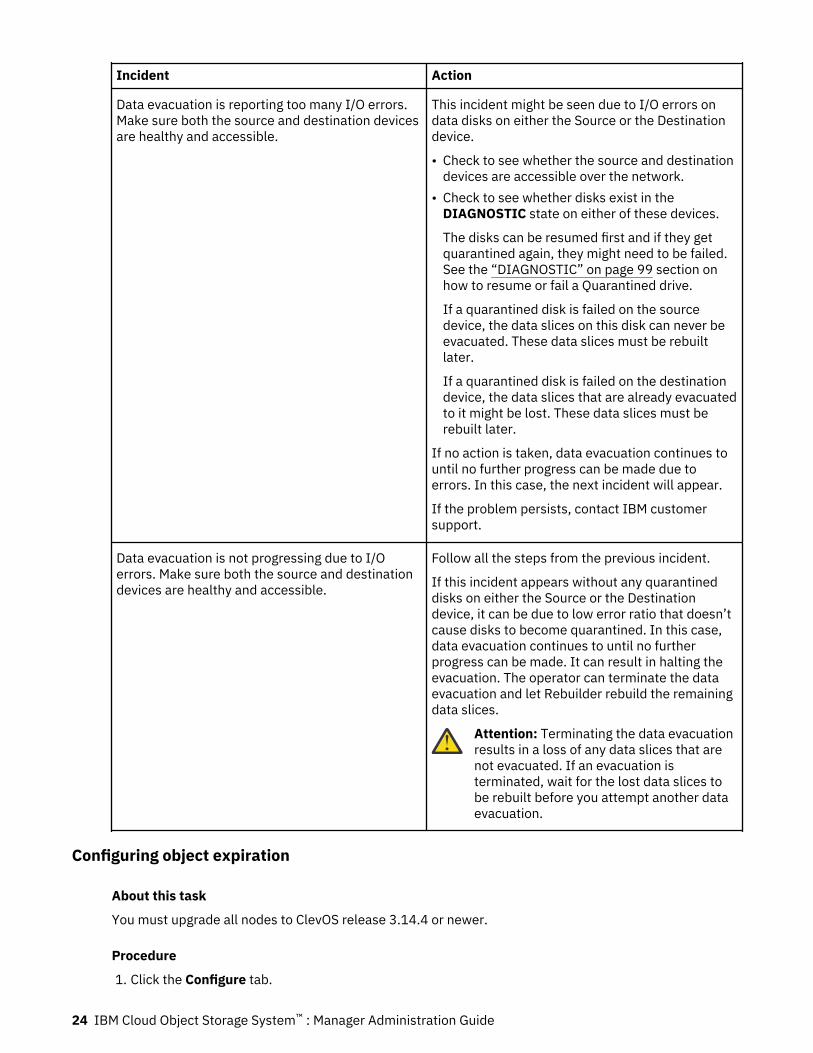
Incident Action
Data evacuation is reporting too many I/O errors.Make sure both the source and destination devicesare healthy and accessible.
This incident might be seen due to I/O errors ondata disks on either the Source or the Destinationdevice.
• Check to see whether the source and destinationdevices are accessible over the network.
• Check to see whether disks exist in theDIAGNOSTIC state on either of these devices.
The disks can be resumed first and if they getquarantined again, they might need to be failed.See the “DIAGNOSTIC” on page 99 section onhow to resume or fail a Quarantined drive.
If a quarantined disk is failed on the sourcedevice, the data slices on this disk can never beevacuated. These data slices must be rebuiltlater.
If a quarantined disk is failed on the destinationdevice, the data slices that are already evacuatedto it might be lost. These data slices must berebuilt later.
If no action is taken, data evacuation continues tountil no further progress can be made due toerrors. In this case, the next incident will appear.
If the problem persists, contact IBM customersupport.
Data evacuation is not progressing due to I/Oerrors. Make sure both the source and destinationdevices are healthy and accessible.
Follow all the steps from the previous incident.
If this incident appears without any quarantineddisks on either the Source or the Destinationdevice, it can be due to low error ratio that doesn’tcause disks to become quarantined. In this case,data evacuation continues to until no furtherprogress can be made. It can result in halting theevacuation. The operator can terminate the dataevacuation and let Rebuilder rebuild the remainingdata slices.
Attention: Terminating the data evacuationresults in a loss of any data slices that arenot evacuated. If an evacuation isterminated, wait for the lost data slices tobe rebuilt before you attempt another dataevacuation.
Configuring object expiration
About this task
You must upgrade all nodes to ClevOS release 3.14.4 or newer.
Procedure
1. Click the Configure tab.
24 IBM Cloud Object Storage System™ : Manager Administration Guide
2. Click Storage Pools in the navigation panel.3. Click the link of a Storage Pool to display the Storage Pool: <storage-pool-name> page.4. In the Object Expiration section, click Configure to display the Configure Object Expiration:
<storage-pool-name> page.5. Click Change in the Object Expiration section.6. Click Enable object expiration and click Update.7. Optional: Configure the scanning and deletion rates
a. Click Change Scanning in the Scanning section.b. Change the rate values as desired and click OK.
Note: Background scanning can also be disabled using this interface.8. Optional: Enable/Disable object expiration on multiple vaults.
a. Select desired vaults in the Vaults tab.b. Click Change in the Vault Settings section in the Vaults tab.c. Select Enable or Disable and click Update to apply that setting on selected vaults in previous page.
9. Optional: Configure the work distribution.
a. Click Change Distribution in the Scanning Work Distribution section in the Access Pools tab.b. Click Customize the scanning work distribution. New access pools must be manually
configured.c. Adjust the sliders or manually enter a value for each access pool. The total distribution must equal
100%.d. Click Update.
VaultsCreate a new vault or configure selected existing vault parameters.
The vault name, description, external access host (container vaults only), and alert parameters can bechanged by pressing Change to modify vault attributes, Setup Vault Migration to move data from onevault to another, or Delete Vault to completely remove this vault and its data from the system. This actionis not reversible. Press Monitor to shortcut back to the Monitor view for this Vault.
CAUTION: Deleting a vault is a permanent action. There is no recovery or restore mechanism for adeleted vault.
Note: If Vault Deletion Authorization is enabled, two System Administrators must approve deleting avault. In order to delete a vault, a System Administrator must first submit a deletion request. This requestmust then be approved for deletion by another System Administrator within 24 hours of submission.
Note: Vaults take approximately 20 minutes / TB to delete. To minimize the operational impact, createnew vaults before deleting old vaults. As space is freed by the deletion process, it will be available for thenew vault (s).
Warning: SecureSlice Algorithm is the algorithm that is used to encrypt new and modified objects.If the secure slice algorithm was modified during the lifetime of the vault, a warning icon isdisplayed. This warning icon indicates that objects in the vault may be encrypted with a differentalgorithm. For standard vaults, DMS can be used move objects to a new vault. In which case, allthe objects are encrypted with the secure slice algorithm specific in the destination vault. For aprocedure to re-encrypt objects stored within other vault types, contact IBM Customer Support.
Configuration
The Slicestor devices associated with this Vault, the width, and the thresholds. Press Change at the top ofthe menu to modify the Alert Level. Selecting the device will shortcut directly to it.
Chapter 3. Configuration 25
The Segment Size is shown in bytes. The initial data file (source data) is divided into segments, and theneach segment is encoded and sliced via the process. The Segment Size may be adjusted when creating avault using the. This applies to all vaults, both Accesser-based and SDK clients.
The vault is used to identify a specific vault, and may be referenced in the Events Console.
Additional Features
Various vault specific properties will be displayed along with their currently defined value.
Deployment
Once a Vault has been created, it must be "deployed" to be visible by an Accesser pool. [This step doesNOT apply to SDK clients.] Available Access Pools are shown; select the plus icon to show devices. PressChange to access the Deployment menu. The Accesser registry update (and Vault availability) may takeup to 5 minutes.
S3 Proxy Settings
A S3 proxy redirect may be configured for this vault.
Access Control
For additional data security, the Vault access IP address can be restricted. Press Change to enterauthorized addresses. [This does NOT apply to SDK clients.]
Authorized Users
Access permissions must be granted for each object vault. Press Change to enter or modify permissions.
Attention: Any time a device is added or a vault, site, cabinet, or an administration configuration ischanged, the Manager device must be backed up by using the Backup and Restore utility.Permanent data loss can occur if the Manager database becomes corrupted. Periodic backupsmust also be performed to preserve historical statistics and log information. See Backup settingson the Administration menu.
OverviewFour types of vaults can be created: management, standard, container, and service vaults.
• Management vaults retain statistics data that is generated within the system.• Standard vaults are used to store user data.• Container vaults are used when the system is in container mode. Containers are created in container
vaults. User data is stored within containers.• Service vaults are needed when the system is operating in container mode. The service vault is used
internally by the system to store container metadata, storage accounts, and access keys.
CAUTION: It is recommended that periodic backups be performed, particularly any time a deviceis added or a vault is changed. Otherwise, permanent data loss can occur if the Manager databasebecomes corrupted.
Vault limitsThere is a limit to the number of vaults the system can contain. Standard and container vaults counttowards this limit, but management and service vaults do not.
The maximum number of vaults is limited to 1000 by default. In some cases, certain systemconfigurations can support up to 1500 vaults. For more information on increasing the vault limit beyond1000 vaults, contact IBM Customer Support.
When the vault count exceeds 95 percent of the vault limit, a warning message appears on the home pagewith the current number of vaults.
The system is nearing the maximum number of 1000 standard vaults (996 are present). Once the limit is reached, standard vault creation requests will be rejected.
When the vault limit is reached, more vault creation requests are rejected.
26 IBM Cloud Object Storage System™ : Manager Administration Guide
Filtering vaults in the vault summary sectionOn the Monitor and Configure Vault Summary pages, a gray box encapsulates a collection of filters bywhich the list of Vaults can be limited.
Note: When Container Mode is enabled, container vaults and service vaults do not appear in the list of allvaults, as access cannot be set on these vaults through the Manager Web Interface.
Vault filters include the following selection options:
• Check boxes for Health and Conversion Compatibility.• Drop-down menus for Storage Pools, Vault Types, IDAs, Access Pools, Tags, Versioning, and
Protection Level.
Standard vaults come in two flavors as determined by the Protection Level setting:Retention
The vault is a protected vault and objects stored within that vault will have retention properties thatwill dictate when these objects can be deleted.
• Drop-down menus for Provisioning Codes, Regions, and Storage Classes if Container vaults exist.
Below this gray box a plain text Search Results field exists.
To filter the list of Vaults, you can select one or more of any of the options in the drop-down menus orcheck boxes.
The Search Results field accepts one or more terms that are separated with a space. It does not supportAND, OR, or None logical operators or keywords.
All filters are combined when you filter the list ((logical)AND). Within each filter, if more than one option isselected, any of those selected options can be included when you filter the list ((logical)OR).
To limit the Vaults that are displayed to the ones with:
• Healthy or Warning states.• Storage Pools ABC or DEF.• Versioning enabled.• The terms Seattle and S3 in their names.
Perform the following steps:
1. Check Healthy and Warning in the Health check boxes.2. Select ABC and DEF in the Storage Pool drop-down menu.3. Check enabled Versioning check box.4. Type Seattle S3 in the Search Results field.
It provides the wanted filtered result.
Management vaultsA Management Vault stores statistics data a device collects locally. The statistics that are collected topopulate the graphs within the Manager Web Interface are important to identify long-term trends insystem performance and planning.
The Management Vaults is also used to store Access Logs. It enables the Access Log to be storedindefinitely whereas the number of Access Logs saved on an Accessor device is limited based on OS disksize. By default, Access Logs are copied to the Management Vault. It is recommend that this setting notbe changed for Accessor devices that host Protected Vaults.
Within 60 minutes of the current Access Log being rotated, it is uploaded to the Management Vault. Whenthe Management Vault is configured initially, the backlog of rotated Access Logs is uploaded slowly intothe Management Vault. It is expected to take a number of hours to complete.
The Access logs can be queried from the Management Vault by using the Cloud Storage Object API. If thesystem is in container mode, these requests must be executed through the Service API. The access logs
Chapter 3. Configuration 27
are stored at <device_uuid>/accessLogs/. The <device_uuid> can be located inconfigureDevice.adm of the appropriate device. The individual Access Logs are named access.log-YYYY-MM-DDTHHMMSSMMM.gz. The time stamp indicates the time that this Access Log was rotated.
A log file that is named access.log-2014-12-08T182701330.gz was from 08 December 2014 at18:27:01.330.
Note: When Backup HTTP access logs is checked, in addition to rotated Access Logs getting uploaded tothe Management Vault, Notification Logs are also uploaded to the Management vault. Notification logs arealso stored under <device_uuid>/ and follow a similar naming convention to that of Access Logs.
In releases prior to ClevOS 3.10.0, management vaults are optional. In a new installation of ClevOs 3.10.0or newer, management vaults are enabled and set to automatic configuration at installation. If you areupgrading to 3.10.0 or newer from a previous version of ClevOS, the system preserves the managementvault settings (enabled or disabled) of the previous release.
If you plan to enable Vault Protection on the system, you must enable a Management Vault with theautomatic configuration. You must also enable the backup of HTTP access logs to the Management Vault.
Management Vaults can be configured through the Configure tab of the Manager Web Interface. From theConfigure Management Vault page, a user can:
• Enable or disable the ability to configure Management Vaults in the system.• Choose between automatic and manual management configuration.
Note: Automatic configuration is recommended. If you plan to enable Vault Protection on the system,you must choose automatic configuration.
The Device Management Vault Configuration displays storage pools what contain devices.
You can choose what content is stored in a Management Vault. The Management Vault options are:
• System configuration• Backup of HTTP access logs.
Note: Backup of access logs option must be selected to enable Vault Protection.
Note: If Redact client information is selected, an "access log redaction time" must also be provided inthe associated input field. The unit of the input is days. Any non-negative integer is valid up to 36500(days). Rotated HTTP access logs in management vaults will not be redacted until at least "access logredaction" days have passed after the log was rotated. When Redact client information is enabled, abutton to the Redaction Status Report displays.
Note: An access log rotation period must be set if redaction is enabled.
– Remove client IP addresses. If Backup HTTP access logs is selected, Redact client IP addressescan also be selected.
• Back up of platform shell audit logs• Backup of device statistics
Note: When automatic configuration is selected, all Management Vault options are selected.
When automatic configuration is selected, the Manager application performs the following items:
• Creates a single Management Vault for each storage pool in the system that has a vault.• Updates the Management Vault of all Slicestor devices in a storage pool to the vault created in that pool.• Assigns Accesser devices to a Management Vault.• Assigns Manager device to the Management Vault with the least number of devices.
CAUTION: If a Slicestor device is replaced while in a pool, then the original device no longer hasan assigned Management Vault and the new device points to the Management Vault.
Automatic configuration follows these rules:
• New Slicestor devices are not assigned a Management Vault.
28 IBM Cloud Object Storage System™ : Manager Administration Guide
• New Accesser devices are not assigned a Management Vault until they are deployed to a vault. At thatpoint, the Management Vault on that pool is assigned.
• New Management Vaults are created on a storage pool when the first vault on that pool is created. TheManagement Vault that is created has the same configuration (width, threshold, secure slice, and so on)as the new vault on the pool.
• A storage pool with Management Vaults can be deleted if the pool contains Management Vaults.• Management Vaults cannot be created, edited, or deleted. Management Vaults for a device cannot be
assigned or removed manually. Management vault's read, write, alert threshold and tags are the onlyeditable.
Note: A Management Vault is not created on a storage pool that has no vaults.
The name and description for the Management Vault is generated automatically. The name is in theformat csinternal-mgmt-poolName with a description of "Stores backups of internal statistic data".
Manual configuration has different restrictions:
• Management Vaults must be manually created/edited/deleted and assigned to devices.• Management Vaults are created through the API or the /configureManagementVault page in the
Manager Web Interface.• Device management vaults can be managed by using a new Device Management Vault Configuration
form.
At any time, a user can disable management vaults in the Manager. It does not delete any pre-existingManagement Vaults but prevents any new data from being written to them.
CAUTION: For a device that is running 3.4, with Management Vault enabled, statistics data will beretained after an OS disk replacement. If the device is imaged to an earlier release, like 3.2.x, thestatistics for that device are lost.
Note: During core software shutdown (upgrades, reboots, ...), it is possible that IO will be attempted tothe management vault. This IO will temporarily result in 503s. The failed IO operation will be retried at alater time. However, the 503s will be included in the access log and may cause the "Device is reportingthat HTTP PUT requests are returning status code 503. " incident to open on the Manager UI. The incidentwill be cleared in a few minutes after the core software starts up.
Standard vaultsAfter the system is set up and a storage pool is available, standard vaults can be created. To use Standardvaults, the system must be operating in vault mode.
As part of the planning phase, a determination needs to be made on the vault width and threshold. Thesedecisions affect the availability, resiliency, performance, and storage capacity of the vault. These settingsshould be used to adjust the characteristics of each vault as wanted for the specific application.
Vaults can be created by:
1. Customizing a configuration2. Leveraging a vault template
In addition, vault access can be restricted based on IP addresses.
Note: It is recommended that periodic backups be performed, particularly any time a device is added or avault is changed. Otherwise, permanent data loss can occur if the Manager database becomes corrupted.
Related concepts“Vault limits” on page 26
Chapter 3. Configuration 29
There is a limit to the number of vaults the system can contain. Standard and container vaults counttowards this limit, but management and service vaults do not.
Container vaultsContainer vaults are used instead of standard vaults when the system is running in container mode. Assuch, container vaults have the same restrictions as standard vaults and they can be created by using thesame method.
Containers are created on container vaults. Object I/O is executed on objects that are stored withincontainers. Direct I/O to container vaults is not permitted.
Related concepts“Vault limits” on page 26There is a limit to the number of vaults the system can contain. Standard and container vaults counttowards this limit, but management and service vaults do not.
Service vaultsThe service vault is needed when the system is operating in container mode. The service vault is createdwhile container mode is being enabled and cannot be deleted until container mode is disabled. Only asingle service vault can be created.
The service vault stores a mapping of container names to container vault, storage accounts, and accesskeys. Therefore, all container I/O fails when the service vault is not accessible from the access devices. Ifthe content of the service vault is lost, the containers are lost as well.
Configuring vault protectionVault Protection allows objects stored in vaults or containers to have associated overwrite and deletionprotection. Protected objects cannot be deleted until the associated data retention duration expires andall legal holds associated with the object are been removed. Once Vault Protection is enabled, it can onlybe disabled if there are no protected vaults, protected containers, or protected mirrors in the system.
Before you beginThe Management Vault must be enabled with automatic configuration and backup of HTTP access logsbefore you can configure Vault Protection.
After Vault Protection is configured, any updates to the system duration values do not affect existingvaults but do apply to new vaults. However, if you modify an existing vault, the updated system durationsettings are used for validation.
Procedure
1. Click the Configure tab.2. In the Configure Vault Protection section, click Configure.3. Select Allow vault protection.
Once vault protection is enabled, it cannot be disabled.a) (Vault Mode only.) The System Retention Duration is the default number of days that a vault's
Retention Duration is set to if no custom Retention Duration is specified at vault creation. Enter acustom value or accept the default value of 730 days. This value must be more than the SystemMinimum Duration and less than the System Maximum Duration. The minimum supported value is 0days, and the maximum is 2,147,483,647 days.
b) The System Minimum Duration is the minimum number of days that a vault or container'sminimum retention period can be set to. Enter a custom value or accept the default value of 0 days.This value must be less than the System Maximum Duration. The minimum supported value is 0days, and the maximum is 2,147,483,647 days.
c) The System Maximum Duration is the maximum number of days that a vault or container's defaultmaximum retention period can be set to. Enter a custom value or accept the default value of 36159
30 IBM Cloud Object Storage System™ : Manager Administration Guide

days. This value must be greater than the System Minimum Duration. The minimum supportedvalue is 0 days, and the maximum is 2,147,483,647 days.
d) Optional: Select Allow permanent retention of objects on the system if you want to enable usersto create vaults or containers that can permanently retain objects.
Attention: Once permanent retention of objects is allowed on the system, it cannot bedisabled.
A dialog box appears. Click Enable.4. Click Update.
What to do next
1. Update the access log rotation settings to ensure that logs are retained for audits of protection activity.2. To permanently retain objects you must also enable permanent retention on the vault or mirror in
Vault Mode, or on the container in Container Mode.
Configuring SecureSlice algorithmTo begin, follow these steps.
Configuring system wide default SecureSlice algorithmConfigure default Secure Slice Algorithm at system level. Select the default setting to be used whencreating new vaults. Existing vaults are not affected by this change.
Procedure
1. Click Configure tab.2. Click Configure SecureSlice Algorithm.3. Select one of the options.4. Click Update to save the configuration.
Configuring SecureSlice algorithm during vault creation
Procedure
1. Click Configure tab.2. Click Storage Pools in left menu.3. Click Create Vault in Vaults sections.4. Click checkbox Enable SecureSlice algorithm.5. Select one of the options.6. Finish vault creation procedure.
Changing SecureSlice algorithm for existing vaults
Procedure
1. Click Configure tab.2. Click Storage Pools in left menu.3. Select one of the storage pools or select one of the vaults (if there’s only one storage pool).4. Click Change.5. Select on the options in dropdown box Enable SecureSlice algorithm. The existing objects in the vault
remain encrypted with the original algorithm. New and modified objects are encrypted with the newalgorithm. For standard vaults, DMS can be used to move objects to a new vault. In which case, all theobjects will be encrypted with the secure slice algorithm specific in the destination vault. For aprocedure to re-encrypt objects stored within other vault types, contact IBM Customer Support.
Chapter 3. Configuration 31
6. Click Update to save the configuration.
Changing SecureSlice algorithm for templates
Procedure
1. Click Configure tab.2. Click Configure button in Template Management section.3. Create new of change existing template for vault of mirror.4. Click checkbox Enable SecureSlice algorithm.5. Select one of the options.6. Finish template creation procedure.
Configuring System Vault Name Index FormatAllows you to configure the system vault name index.
About this task
Procedure
At the global system level, set the Vault Index Version to be either Version 2 or Version 4 on theConfigure page.When any new vaults are created with the Name Index Enabled feature, the configured global default forIndex Version will be used, provided the Index Version is not overridden by the setting at the storage poolor at the vault.
Related tasks“Selecting Vault Name Index Format” on page 32
Selecting Vault Name Index Format
About this taskSee the Vault Index Version - Feature Description Document and the following related information formore details on selecting the Vault Name Index Format.
Creating vaultsTo begin vault creation, follow these steps.
Procedure
1. In the Configure tab, click Create Vault in the Summary section.
2. If a storage pool was not created already, the Create New Storage Pool page appears.3. In the General section, complete these fields:
Field Label Acceptable Field Value
Name Each vault must be uniquely named (maximum of 255characters); this name is used by the Manager for all referencesto this vault. Vault names can include underscores andalphanumeric characters. The vault name can also containperiods (.), but the name cannot start or end with a period orcontain more than one period in a row. The first character of thename must be a letter, underscore, or number.
32 IBM Cloud Object Storage System™ : Manager Administration Guide
Field Label Acceptable Field Value
Description An optional free-form description can also be entered.Information that you might include in the description field mightbe initiator host name and IP address, names and phone numbersof administrators, and key users of the vault.
Tags Tags can be created and or assigned to a vault before the vault iscreated. For more information, see the Tags section.
Organization When you create a vault, you can assign it to an organization. Thedropdown menu does not appear if you only have oneorganization. See Creating an organization in the Security chapterand Editing an organization in the Security chapter.
4. In the Configuration section, several options display.
• When the width of the pool for this vault is greater than 6, complete the following fields:
Field Label Acceptable Field Value
Width This setting is referred to as the width of the vault andcorresponds to the number of slices into which all data in thevault is split.
Vault width must be a factor of the storage pool width. TheManager Web Interface allows any vault width greater than orequal to 6 and less than or equal to 60.
Threshold The minimum number of slices that must be available toperform a read. Pre-defined, supported thresholds arepresented when the drop-down list is clicked. The vaultthreshold, always less than the width, determines the reliabilityof the vault. If the set of available Slicestor devices is such thatthe number of slices falls below this threshold, the vaultcontent cannot be read, and the vault appears as red in theMonitor application.
The Manager Web Interface allows any value between 1 andVault Width, inclusive.
If the vault is on a storage pool that spans multiple sites, theManager Web Interface warns the user if the selected thresholdis high enough such that a single site outage affects read andwrite availability.
Chapter 3. Configuration 33
Field Label Acceptable Field Value
Write Threshold The Manager Web Interface allows any value such that all thefollowing are true:
– Write Threshold > Threshold.
CAUTION: Write Threshold = Threshold is allowed ifThreshold = Vault Width or if Vault Width < 6.
– Write Threshold ≤ Vault Width.– (Write Threshold + Threshold) > Vault Width.
Write Threshold defaults to Threshold + 2, if that is within theallowed range. Otherwise, the selected Write Threshold is thehalfway point between the minimum allowed Write Thresholdand Vault Width, rounded up. This value is selected by default inthe Write Threshold drop-down when Threshold is selected.This value is also used as the Write Threshold when a vault iscreated through the Manager REST API and a Write Threshold isnot specified.
If the vault is on a storage pool that spans multiple sites, theManager Web Interface warns the user if the selected writethreshold is high enough such that a single site outage affectswrite availability.
Alert Level Optional. If the set of available Slicestor devices is such that thenumber of slices is between the write threshold and the alertlevel exclusive, the vault icon is yellow in the Monitorapplication. In this case, the vault is still fully functional.
Attention: If the Threshold is set such that the loss of one site would make Vaults eitherunusable or read-only, the Manager Web Interface displays a confirmation dialog box thatasks the operator if they accept the settings with the risks they present.
If only the Threshold causes an issue:
Warning: This IDA configuration is susceptible to read availability issues during a single site outage. Do you still wish to continue?
If the Threshold and Write Threshold cause issues:
Warning: This IDA configuration is susceptible to read and write availability issues during a single site outage. Do you still wish to continue?
Click Cancel or OK to change or keep the settings.• When the width of the pool for this vault is 3 - 9, select a vault optimization to create a
Concentrated Dispersal vault:
34 IBM Cloud Object Storage System™ : Manager Administration Guide
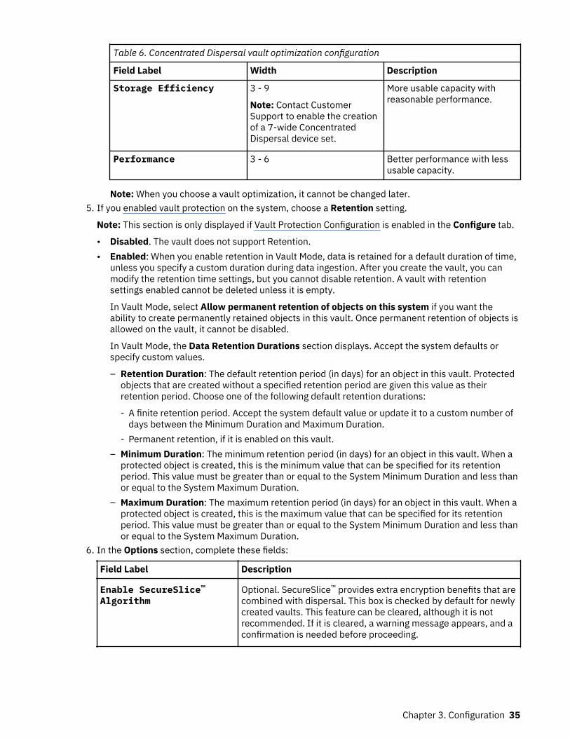
Table 6. Concentrated Dispersal vault optimization configuration
Field Label Width Description
Storage Efficiency 3 - 9
Note: Contact CustomerSupport to enable the creationof a 7-wide ConcentratedDispersal device set.
More usable capacity withreasonable performance.
Performance 3 - 6 Better performance with lessusable capacity.
Note: When you choose a vault optimization, it cannot be changed later.5. If you enabled vault protection on the system, choose a Retention setting.
Note: This section is only displayed if Vault Protection Configuration is enabled in the Configure tab.
• Disabled. The vault does not support Retention.• Enabled: When you enable retention in Vault Mode, data is retained for a default duration of time,
unless you specify a custom duration during data ingestion. After you create the vault, you canmodify the retention time settings, but you cannot disable retention. A vault with retentionsettings enabled cannot be deleted unless it is empty.
In Vault Mode, select Allow permanent retention of objects on this system if you want theability to create permanently retained objects in this vault. Once permanent retention of objects isallowed on the vault, it cannot be disabled.
In Vault Mode, the Data Retention Durations section displays. Accept the system defaults orspecify custom values.
– Retention Duration: The default retention period (in days) for an object in this vault. Protectedobjects that are created without a specified retention period are given this value as theirretention period. Choose one of the following default retention durations:
- A finite retention period. Accept the system default value or update it to a custom number ofdays between the Minimum Duration and Maximum Duration.
- Permanent retention, if it is enabled on this vault.– Minimum Duration: The minimum retention period (in days) for an object in this vault. When a
protected object is created, this is the minimum value that can be specified for its retentionperiod. This value must be greater than or equal to the System Minimum Duration and less thanor equal to the System Maximum Duration.
– Maximum Duration: The maximum retention period (in days) for an object in this vault. When aprotected object is created, this is the maximum value that can be specified for its retentionperiod. This value must be greater than or equal to the System Minimum Duration and less thanor equal to the System Maximum Duration.
6. In the Options section, complete these fields:
Field Label Description
Enable SecureSlice™Algorithm
Optional. SecureSlice™ provides extra encryption benefits that arecombined with dispersal. This box is checked by default for newlycreated vaults. This feature can be cleared, although it is notrecommended. If it is cleared, a warning message appears, and aconfirmation is needed before proceeding.
Chapter 3. Configuration 35

Field Label Description
Enable Versioning Check to enable versioning on this vault.
Note: Versioning cannot be enabled if the Protection Level is setto Retention.
Delete Restricted This feature allows Security Officers to restrict vault accesspermissions such that users with write access to the vault are notable to delete objects from the vault. Additionally, objectversioning is enabled by default so that existing content ispreserved upon overwrite when using a write-by-name interface.Users that are granted owner permissions on a Delete Restrictedvault are allowed to delete objects and versions.
Enable Server sideencryption with Customerprovided keys (SSE-C)
This option is use to protect the data with encryption keys.
Restrictive AccessControl (cannot bechanged later)
This option defines the type of Access Control and cannot bechanged later.
Note:
Restrictive Access Control property is only applicable onprotected vaults and protected mirrors.
To see it, enable protection on the system then Create protectedmirror/protected vault. Hit create vault option and it will show inthe Manager UI
Enable object expiration • Object expiration is enabled by default if object expiration isalready enabled at storage pool; otherwise, it is disabled bydefault.
• To enable object expiration at vault level, you must enable it atstorage pool level.
• To enable object expiration, versioning should not be enabled,name index must be enabled, and a vault should not be part of amirror or not part of DMS.
7. In the Quotas section, complete these optional fields if wanted:
Field Value
Soft Quota Optional. If wanted, select a value for a soft quota. A notificationis sent to the Event Console, if the soft quota setting is exceeded.It does not cause restrictions to usage. Setting the quota higherthan the total space available in one or more storage pools thatare associated with this vault has no effect.
Hard Quota Optional. If wanted, enter a hard quota value. The Accesserdevice (or application) does not permit the user to exceed thehard quota value for this vault. A notification is also sent to theEvent Console if the hard quota setting is exceeded. Setting thequota higher than the total space available in one or more storagepools that are associated with this vault has no effect.
8. In the Advanced Index Settings section, Name Index Enabled is checked by default for Standardvaults and you can enable Recovery Listing.
36 IBM Cloud Object Storage System™ : Manager Administration Guide
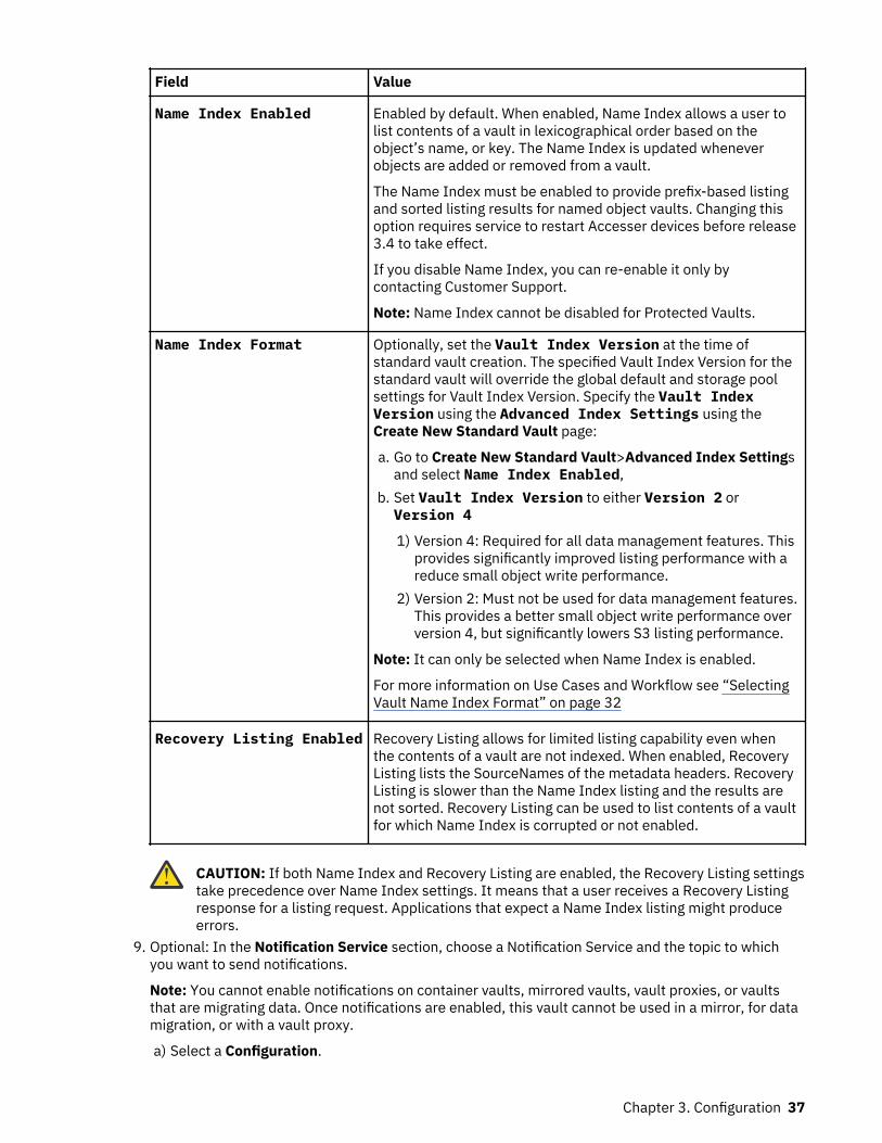
Field Value
Name Index Enabled Enabled by default. When enabled, Name Index allows a user tolist contents of a vault in lexicographical order based on theobject’s name, or key. The Name Index is updated wheneverobjects are added or removed from a vault.
The Name Index must be enabled to provide prefix-based listingand sorted listing results for named object vaults. Changing thisoption requires service to restart Accesser devices before release3.4 to take effect.
If you disable Name Index, you can re-enable it only bycontacting Customer Support.
Note: Name Index cannot be disabled for Protected Vaults.
Name Index Format Optionally, set the Vault Index Version at the time ofstandard vault creation. The specified Vault Index Version for thestandard vault will override the global default and storage poolsettings for Vault Index Version. Specify the Vault IndexVersion using the Advanced Index Settings using theCreate New Standard Vault page:
a. Go to Create New Standard Vault>Advanced Index Settingsand select Name Index Enabled,
b. Set Vault Index Version to either Version 2 orVersion 4
1) Version 4: Required for all data management features. Thisprovides significantly improved listing performance with areduce small object write performance.
2) Version 2: Must not be used for data management features.This provides a better small object write performance overversion 4, but significantly lowers S3 listing performance.
Note: It can only be selected when Name Index is enabled.
For more information on Use Cases and Workflow see “SelectingVault Name Index Format” on page 32
Recovery Listing Enabled Recovery Listing allows for limited listing capability even whenthe contents of a vault are not indexed. When enabled, RecoveryListing lists the SourceNames of the metadata headers. RecoveryListing is slower than the Name Index listing and the results arenot sorted. Recovery Listing can be used to list contents of a vaultfor which Name Index is corrupted or not enabled.
CAUTION: If both Name Index and Recovery Listing are enabled, the Recovery Listing settingstake precedence over Name Index settings. It means that a user receives a Recovery Listingresponse for a listing request. Applications that expect a Name Index listing might produceerrors.
9. Optional: In the Notification Service section, choose a Notification Service and the topic to whichyou want to send notifications.
Note: You cannot enable notifications on container vaults, mirrored vaults, vault proxies, or vaultsthat are migrating data. Once notifications are enabled, this vault cannot be used in a mirror, for datamigration, or with a vault proxy.
a) Select a Configuration.
Chapter 3. Configuration 37

For more information, see “Configuring notifications” on page 88.
Note: Notifications are sent only for new operations that occur after the vault is assigned to theconfiguration.
b) Select the topic to which you want to send notifications.
• Default: The default topic specified in the configuration.• Custom: Enter a topic name to override the default topic specified in the configuration.
Note: When in container mode, topic can be set at the container level using the Service API.10. Click Save.11. The Access Pools available for deployment are displayed on the Vault Summary section.
This step is not necessary for Simple Object vaults that are accessed through the Accesserapplication.
Create vaults by using vault templatesAn alternative approach to vault creation is based on the use of vault templates.
These templates allow a user to create multiple vaults with the same parameters quickly and enablecommon vault configurations to be leveraged across multiple users. A vault template is created on astorage pool and can then be used during the creation of a vault. All parameters that are set in the vaulttemplate apply to the vault. When a storage pool is created, the following steps can be performed tocreate a vault template:
1. Navigate to the top-level Configure tab.2. Click Configure in the Template Management section.3. Select a Storage Pool for Vault Template from the menu in the Template Management page.4. Click Create in the Vault Template section.5. A new vault template can be created by either importing an existing template or customizing a new
template.6. When customizing a new template, you can enter an optional provisioning code (for example, USEast). This code determines where data is stored and which vaults are written when using vaultprovisioning. The provisioning code must be unique for each vault (255 characters max) and defaultsto the vault name, once entered. This parameter is typically the S3 Put Bucket locationConstraintor region. In container mode, PUT bucket requests create containers instead of vaults. Therefore, theprovisioning code on the vault template is only supported in vault mode.
• In the Provisioning Code field, you can enter a region (255 characters max). This region is used toindicate where the contents of the vault reside. The locationConstraint shown for thecontainer(s) associated with the vault in the S3 GET Service Extended and S3 GET Bucket LocationAPIs are populated with this value. The region code on the vault template is only supported in vaultmode.
• In the Provisioning Code field, you can enter a storage class (255 characters max). The storage classis used as a classification assigned to all objects stored within the vault. The header x-amz-storage-class shown in the S3 GET/HEAD object and the storageClass in the response body ofthe S3 GET Bucket are populated with this value. The storage class on the vault template is onlysupported in vault mode.
7. In addition to providing vault configuration parameters, Accesser devices can be selected fordeployment and access to vaults can be controlled by specifying IP addresses. For more informationon these configuration parameters, see “Creating vaults” on page 32
8. Select name index format for the template. For more information on selection see the FDD discussingVault Index Version Selection. Optionally, set the Vault Index Version at the time of standardvault creation. The specified Vault Index Version for the standard vault will override the global defaultand storage pool settings for Vault Index Version. Specify the Vault Index Version using theAdvanced Index Settings using the Create New Standard Vault page: You can chose one ofthree options.
38 IBM Cloud Object Storage System™ : Manager Administration Guide
a. Storage Pool Default: If selected the value would be inherited from the storage pool selected.b. Version 4: Required for all data management features. This provides significantly improved listing
performance with a reduce small object write performance.c. Version 2: Must not be used for data management features. This provides a better small object
write performance over version 4, but significantly lowers S3 listing performance.
Note: It can only be selected when Name Index is enabled.
For more information on Use Cases and Workflow see “Selecting Vault Name Index Format” on page32
9. When complete, click Save.
Note:
(Vault Mode Only) If one or more templates exist or are created, it is possible to specify a defaulttemplate (Configure > Default Vault Template Configuration). This default template is used when theProvisioning API is enabled and no provisioning code is specified. Vault templates with Retention enabledcannot be used as a default template.
A vault can be created by using the newly created template.
1. On the Storage Pool: {storage-pool-name} page, the new template appears under the VaultTemplates section.
2. Click Create Vault next to the template to be used.3. Provide the needed information. The newly created vault inherits the SecureSlice™ state (enabled or
disabled) from the Vault Template.4. Click Save.
Vault templates can be edited and deleted as well:
1. On the Storage Pool: {storage-pool-name} page, in the Vault Templates section, select the vaulttemplate to be edited/deleted, and a new page appears.
2. Click Change or Delete Vault Template from the action bar at the top of the page.3. Edit the template, make any revisions, and click Save.
Vault proxy settingsThe S3 proxy allows transparent access to data stored in a S3 bucket as though it was stored in an IBMvault.
Only supported in vault mode. Protected Vaults do not support Vault Proxy.
By clicking Change on the action bar, a user can configure proxy settings on a vault. Multiple proxy typesare available to select.
A proxy redirect may be configured for S3 data migration or for another vault on this system:
1. Select the Proxy Type, either S3 or Internal.2. Enter the Endpoint URL and the Bucket Name.
An optional Access Key ID and Secret Access Key may also be required.3. Select the vault to proxy.
Ensure that the vault is deployed to one or more access pools and there is at least one commonauthorized user or group between the proxied vault and the vault configuring the proxy.
Warning: When using an internal proxy, failure to configure common access permissions forboth vaults could result in I/O errors.
The system will attempt to read the object from this vault, and will redirect the Read to the proxy locationif the object is not found (i.e. it has not been migrated). This feature does not migrate data.
Chapter 3. Configuration 39
At any point, you can disable the proxy setting by clicking the disable radio button on the Manager WebInterface.
Vault securityVaults can be protected from unauthorized mounts and accessed through an IP filtering access controllist and assigned vault users.
Limit vault access by IP
CAUTION: For unrestricted access to a vault, do not perform these steps.
1. Click Change in the Access Control section of the Vault Configuration page.2. Enter the clients that are allowed access to the mirror in the Authorized IP Addresses text field.
These values, which are separated by a space or a comma, can be either:
• Individual host names• Individual IP addresses (in IPv4 or IPv6 format)• Classless InterDomain Routing (CIDR) Notation for a range of clients
3. Click Update to apply the changes.
Note: When you remove an IP address from the list, changes do not take effect until a new session isstarted.
Classless InterDomain Routing (CIDR) Notation
CIDR allocates IP addresses and routes Internet Protocol packets.
The notation shows a compact representation of an IP address and its routing prefix.
The CIDR number comes from the number of 1s in the subnet mask when converted to binary.
192.168.100.0/24 represents the IPv4 address and its associated routing prefix 192.168.100.0. Itssubnet mask is 255.255.255.0 or 11111111.11111111.11111111.00000000 in binary. It equals 24ones, or `/24 (pronounced "slash twenty-four"). fe00:d7::6/64 represents an IPv6 address and itsassociated routing prefix fe00:d7::6. Its subnet mask is /64.
Limit access by userThis method is applicable for vault mode only. In container mode, user access to containers is controlledvia container configuration, which can be modified via Cloud Object Storage requests.
If you are logged in with Super User or Security roles, you can assign vault access here or from theSecurity tab.
Note: Vaults can be protected from unauthorized mounts and accessed through an IP filtering accesscontrol list and assigned vault users.
Vault access permissions must be entered for each user of an object vault. These permissions can bechanged later.
Anonymous users can access a vault by using 1 of three levels of permission:
• R/W (Read/Write/Delete)
Note: Anonymous R/W/D is not supported on Protected Vaults.• R (Read Only)• None (no access, the default)
Specified users can access a vault by using 1 of three levels of permission:
• Owner (Read/Write/Delete)• R/W (Read/Write/Delete)
40 IBM Cloud Object Storage System™ : Manager Administration Guide

• R (Read Only)• None (no access, default), unless created via API
The Owner option is inherited when a vault is created through the (provisioning API). It can also beassigned by an account that has the Security Officer role. The Owner option must be set to delete a vault.
Note: For more information, see “Configure provisioning API” on page 76.
TagsTo support grouping and managing a collection of items, you can assign a specific tag to one or morevaults or devices.
Creating a tagFollow these steps to create a tag.
Procedure
1. Click the Configure tab to display the top-level Configure page.2. Click Configure Tags.3. Enter the name of the new tag in the Tag Quick Creation field.4. Click Create Tag in the upper right corner of the window.
Note: Tags can also be created from when you Create Vaults, Edit Vaults, or Edit Devices.
Assigning a tagFollow these steps to assign a tag to a vault/device.
Procedure
1. Click the Configure tab to display the top-level Configure page.2. Click Configure Tags.3. Click the tag that you want to assign to a vault/device.4. Search for the vaults/devices that have the tag that is assigned to it, under the Tag Association sub
section.You can search for specific vaults/devices by using the sorting options.
5. Select one or more vaults/devices to be assigned to the tag and click Update on the upper rightportion of the window.
Editing a tagFollow these steps to edit a tag.
Procedure
1. Click the Configure tab to display the top-level Configure page.2. Click Configure Tags.3. Click the tag that you want to modify.4. Change the name of the tag if wanted.5. Change the description of the tag if wanted.6. Click Update in the upper right corner of the window.
Deleting a tagFollow these steps to delete a tag.
Procedure
1. Click the Configure tab to display the top-level Configure page.
Chapter 3. Configuration 41
2. Click Configure Tags.3. Click the tag that you want to delete.4. Click Delete Tag in the upper right corner of the window.
The Manager Web Interface then asks for confirmation.5. Click Delete in the upper right corner of the window to delete the tag.
Vault data migrationData can be copied from one standard vault to another standard vault by using vault migration. Vaultmigration is not supported on vaults with the Retention protection level enabled, or on service, container,and management vaults.
Configuring a vault migrationFollow these steps to configure a Vault data migration.
Before you begin
Before you configure a Vault data migration, an operator must perform the following item:
• Upgrade all Slicestor® Nodes in the specified Vaults Storage Pools to 3.7.1 or later.
Procedure
1. Navigate to a Vault to be migrated.2. Click Setup Vault Migration in the Vault action bar.3. Select the appropriate option for this migration:
a) Migrate data from this specified Vault to another Vault.b) Migrate data to this specified Vault from another Vault.
4. Make a choice, depending on the selection made in the previous step:a) If this Vault is intended as the source, select whether to create the destination Vault or choose an
existing Vault from the drop-down.b) If this Vault is intended as the destination, choose a source Vault from the drop-down.
5. Check the Rename Destination Vault check box, if applicable to this migration.Selecting this option renames the destination Vault with the source Vaults name. It also applies thesource Vaults Access Pool deployments, allowed IP addresses, and authorized user permissions to thedestination. This option is used when the destination Vault is intended to replace the source Vault anda continuous I/O to the source vault exists.
6. If you are configuring a migration between two existing Vaults, click Finish Setup to save yourchanges. If you are configuring a migration to a new Vault, click Proceed to Create Vault.
7. If it is a migration between two existing Vaults, skip to the “Monitoring a vault migration” on page 42section. Otherwise continue with the following steps.
8. Create the destination Vault by using the same procedure as standard Vault creation.
Note: If the Rename Destination Vault option was checked, the Vault Name field is read-only andcompleted with the source Vault's name.
Monitoring a vault migrationFollow these steps to execute a Vault data migration:
About this taskAfter a migration is configured, the next step is to start and monitor the migration.
Procedure
1. Navigate to the destination Vault configured in the migration.
42 IBM Cloud Object Storage System™ : Manager Administration Guide
For the first few minutes, Start is unavailable. It is done to ensure that the necessary configurationchanges are propagated to all devices.
2. When Start is available, click it to begin the migration.3. During the migration the following options are available:
• Pause the migration.• Change the migration throttle. The migration rate can be throttled by MB/sec and objects/sec.• Abort the migration. It halts progress and leave all data copied to the destination vault in its current
location. Abort can be executed at any point during the migration before completion.4. Upon start, the migration begins scanning all objects on the source Vault to determine how many
objects to migrate.5. After the migration is finished scanning, a progress bar showing the percentage of objects that are
migrated appears.6. The migration is finished when the progress bar reaches 100%. The UI reflects this completion.
What to do next
The migration might encounter a scenario where scanning or migration is blocked. It can occur for variousreasons (for example, one of the Vaults is below threshold).
When blocked, the migration pauses and waits for user intervention. Click Resume to continue themigration.
During the migration, some objects can fail to migrate. The migration attempts to migrate all objects andtrack the ones that fail to copy. If failed objects exist at the end of the migration, the UI presents the userwith two options:
• Retry the failed objects. It attempts to retry any objects that failed. If any objects fail again, the sameUI widget appears.
• Complete with Failures. Click to mark the migration as done and no attempt is made to migrate thefailed objects again.
All active vault migrations can be viewed on the Vault Summary page. A Vault Migrations tab appearswhen active migrations exist in the system.
The migrations can be filtered by Migration Status, source and destination vault health, and source anddestination Storage Pool. After a migration is complete, the record appears in the summary table for 72hours. After that time, the migration will not be shown.
Vault mirrors
OverviewTo support two site configurations, the concept of a mirror is introduced, which links a vault at each sitetogether.
Note: Only standard vaults can be part of mirrors, and only retention vaults can be part of protectedmirrors.
CAUTION: The number of vault mirrors supported on a system is limited to the number of vaultspresent when the vault mirror is created. If the system has a vault limit of 1000 and currentlycontains 999 vaults, then the mirror can be created if an initial vault is provided. If the system hasa vault limit of 1000 and currently contains 1000 vaults, then the vault mirror creation is rejectedregardless of whether an initial vault is provided.
Filter vault mirrors in the vault summary section
On the Monitor and Configure Mirror Summary pages, a gray box encapsulates a collection of filters bywhich the list of Vault Mirrors can be limited.
These filters include:
Chapter 3. Configuration 43
• Drop-down menus for Access Pools and Storage Pools.• Check boxes for Health.
Below this gray box also exists a plain text Search Results field.
To filter the list of Vault Mirrors, you can select one or more of any of the options in the drop-down menusor check boxes.
The Search Results field accepts one or more terms that are separated with a space. It does not supportAND, OR, or None logical operators or keywords.
All filters are combined when you filter the list ((logical)AND). Within each filter, if more than one option isselected, any of those selected options can be included when you filter the list ((logical)OR).
To limit the Vault Mirrors displayed to the ones with:
• Healthy or Warning states.• Storage Pools ABC or DEF.• The terms Seattle and S3 in their names.
Perform the following steps:
• Check Healthy and Warning in the Health check boxes.• Select ABC and DEF in the Storage Pool drop-down menu.• Type Seattle S3 in the Search Results field.
The wanted filtered result is provided.
Creating a vault mirror
About this task
CAUTION: The individual vaults can differ in settings (such as IDA and SecureSlice). The mirrordisplays data that is stored in both underlying vaults with two caveats:
• Usable Capacity is limited to the size of the smaller vault.• Used Capacity is reported as the greater used capacity of the vaults.
It is highly recommended that the storage pools are equal usable capacity, as any "extra" capacityin one or the other storage pools is unusable by the vault mirror.
Attention: Vault mirrors cannot be created if the system has reached the vault limit.
If you want to create a protected mirror, see “Creating a protected vault mirror” on page 49.
Procedure
1. Navigate to the Configure tab.2. Click Create Mirror under the Summary heading.
The Create Mirror page appears.3. Enter a name for the vault mirror in the Name field.4. Enter an optional description in the Description field.5. Select from one of the three Mirror Write Configurations: Asynchronous, Synchronous, or HardSynchronous:Asynchronous
(Writes and Synchronous Deletes)
A write response is returned once either vault has confirmed the write was successful. A deleteresponse is returned once both vaults have responded, only one vault needs to confirm the deletewas successful.
44 IBM Cloud Object Storage System™ : Manager Administration Guide

Synchronous
(Writes and Deletes)
A response is returned once both vaults have responded, only one vault needs to confirm theoperation was successful. This means the mirror can handle one vault being inaccessible andhence is more tolerant to outages.
Hard Synchronous
(Writes and Deletes)
A response is returned once both vaults have responded, both vaults need to confirm theoperation was successful. This means the mirror cannot handle any vaults being inaccessible andhence is not tolerant to outages.
6. If a vault exists that should serve as the first vault in the vault mirror, select that vault from the Vaultdrop-down menu.
There are two primary use cases associated with seeding a vault mirror with an existing vault:
a. Migrate an existing vault to be part of a persistent vault mirror. This workflow uses the vault mirrorsynchronization capability to migrate from a single vault to a vault mirror.
b. Migrate existing vaults to a new vault. This workflow uses the vault mirror synchronizationcapability to migrate data. The vault mirror is temporary and is deleted after the data is migratedto the new vault.
CAUTION: To make this transition transparent to the client, a short outage is needed.
1) In both use cases, perform the following steps:
a) Rename the existing vault to something new.b) Create a vault mirror with the existing vaults original name.c) Create second vault.d) Perform an I/O operation on the vault mirror to initialize the synchronization.
2) With the second use case, also perform the following steps:
a) Allow the synchronization process to complete.b) Delete the vault mirror.c) Delete the original vault.d) Rename the new vault with the original vaults name.
7. Click Save to create the vault mirror.The Mirror:<Mirror Name> page displays with an alert that indicates:
Mirror creation successful
8. If an existing vault was used as the basis of a mirror, skip to Step 9, otherwise follow these steps:a) Click Create Vault 1 to add the first vault to the vault mirror.
The Create New Standard Vault page displays.b) Click Continue to begin creating the vault.c) Follow the steps in “Creating vaults” on page 32 to create the standard vault.
When the width of the pool for this vault is 3 - 6, you can also choose to enable ExtendedAvailability for a mirror with Concentrated Dispersal vaults. Enable Extended Availability to ensurethat you can read and write to the mirror if a Slicestor device outage occurs on one side and theother side is unavailable. However, this reduces usable capacity.
The Mirror:<Mirror Name> page displays.9. Click Create Vault 2 to add the second vault to the vault mirror.
The Create New Standard Vault page displays.
Chapter 3. Configuration 45
10. Click Continue to begin creating the vault.11. Follow the steps in “Creating vaults” on page 32 to create the standard vault.
When the width of the pool for this vault is 3 - 6, you can also choose to enable Extended Availabilityfor a mirror with Concentrated Dispersal vaults. Enable Extended Availability to ensure that you canread and write to the mirror if a Slicestor device outage occurs on one side and the other side isunavailable. However, this reduces usable capacity.
The vault mirror is now complete.
Creating mirrors by using mirror templatesAn alternative approach to mirror creation is based on the use of mirror templates. These templates allowa user to create multiple mirrors with the same parameters quickly and enable common mirrorconfigurations to be leveraged across multiple users.
About this task
A mirror template is created and can then be used during the creation of a mirror and both the vaults thatare mirrored. All parameters set in the mirror template apply to the mirror and to the vaults that werecreated with the mirror. The following steps can be performed to create a mirror template.
If you want to create a protected mirror by using a template, see “Creating protected mirrors by usingmirror templates” on page 51.
Procedure
1. Navigate to the top-level Configure tab.2. Select Configure in the Template Management section.3. Click Create Mirror Template, from the Mirror Template section.
A new page appears where a new mirror template and two vault templates can be created.
When customizing, an optional provisioning code can be entered (for example, US East). This codedetermines where data is stored and which vaults are written when you are using vault provisioning. Inaddition to providing mirror configuration parameters, Accesser devices can be selected fordeployment and access to mirrors can be controlled by specifying IP addresses. For more informationon these configuration parameters, see “Creating vaults” on page 32
4. Click Save.5. To create a mirror from the template, click Create Mirror from Template.6. Provide the necessary information and click Save.
What to do next
Note: It is possible to specify a default template, which can be either a mirror template or a vaulttemplate. This default template is used when the Provisioning API is enabled and no provisioning code isspecified.
Mirror templates can be edited and deleted as well.
1. From the Template Management page, in the Mirror Templates section, select the mirror template tobe edited/deleted, and a new page appears.
2. Click Change or Delete Mirror Template from the action bar at the top of the page.3. Edit the template, providing any revisions, and click Save.
46 IBM Cloud Object Storage System™ : Manager Administration Guide
Deploying a vault mirrorWriting and reading objects from the mirror is not possible until the mirror is deployed to one or moreAccesser devices.
About this taskIf you are using Concentrated Dispersal vaults in the mirror, both vaults must be created before the mirrorcan be deployed. Both vaults must be Concentrated Dispersal vaults with the same Vault Optimization.For more information, see “Creating vaults” on page 32.
Procedure
1. Click Change on the Deployment action bar.2. Check the Accesser devices to which the mirror should be deployed.
Note: Protected mirrors cannot be deployed with just one protected vault in the mirror. The vault 1and vault 2 cannot be independently deployed to an Accesser device while they are part of a protectedmirror.
3. Click Update.
Setting vault mirror permissionsAccess to the mirror can be restricted to one or more hosts or IP addresses.
See “Vault security” on page 40 for instructions on how to restrict access.
Editing a vault mirror
About this task
Click Change at the top of the Configure Mirror page to change the mirror name, Description, MirrorWrite Configuration, etc. If it is a protected mirror, you can also change the protection level if there areno vaults in the mirror.
Note: There are three available Mirror Write Configurations:
Asynchronous
(Writes and Synchronous Deletes)
A write response is returned once either vault has confirmed the write was successful. A deleteresponse is returned once both vaults have responded, only one vault needs to confirm the delete wassuccessful.
Synchronous
(Writes and Deletes)
A response is returned once both vaults have responded, only one vault needs to confirm theoperation was successful. This means the mirror can handle one vault being inaccessible and hence ismore tolerant to outages.
Hard Synchronous
(Writes and Deletes)
A response is returned once both vaults have responded, both vaults need to confirm the operationwas successful. This means the mirror cannot handle any vaults being inaccessible and hence is nottolerant to outages.
In addition, six vault-specific settings can be modified:
• Versioning.• Delete Restricted.• Soft Quota.
Chapter 3. Configuration 47
• Hard Quota.• Name Index Enabled.• Recovery Listing Enabled.
Note: In a protected mirror, only Soft Quota, Hard Quota, and the Description can be modified. Theprotected mirror's retention settings or protection level can only be updated if it is empty and does nothave any vaults associated to it.
Changes to these values apply to both vaults in the mirror. To change these values, perform the followingsteps:
Procedure
1. Click Change on the Vault Settings action bar.2. Click Update after you make the wanted changes.
Breaking a vault mirrorFollow these steps to break a mirrored vault configuration.
Before you beginBreaking a mirror removes the relationship between vaults. The relationship cannot be reestablished. Thevaults and object data are not deleted. Breaking a mirror does not delete the two vaults. Both vaultsretain existing objects and their respective current configuration. However, the system no longersynchronizes the content automatically.
CAUTION: If the mirror is using Concentrated Dispersal, proceed with caution when breaking themirror. The vault IDAs in the mirror will provide a lower level of data reliability and availabilitywhen used in a non-mirrored setup.
Procedure
1. Click Delete Mirror at the top of the Configure>Mirror page.2. Click Break Mirror in the Delete Mirror Configuration page.3. Enter your Password.4. Optional: From the Select a vault menu, choose one of the mirror's vaults to be renamed and
redeployed to match the mirror.
Note: This is a mandatory action for Protected Mirrors and is only optional for Standard Mirrors.5. Click Break.
Results
If you chose a vault to rename and redeploy, the selected vault is renamed to have the same name as themirror, and is then deployed to the same access pools as the mirror. The vault you did not select stillexists, but is not deployed to any access pools.
If you did not choose a vault to rename and redeploy, then both vaults still exist but are not deployed toany access pools.
Destroying a vault mirrorFollow these steps to destroy a mirrored vault configuration.
Before you begin
CAUTION:
Destroying a mirror deletes the mirror and its associated vault(s), but only if it is empty. This is apermanent action. There is no process to recover or restore the deleted vault(s) or mirror.
48 IBM Cloud Object Storage System™ : Manager Administration Guide
Note:
1. There should be no active writes during the Destroy Mirror action on standard or protected mirrorssince it can result in destruction of object data.
2. The Destroy Mirror functionality may not work properly with SOH objects.3. The destroy action is not supported if both name index and recover listing are disabled.
Procedure
1. Click Delete Mirror at the top of the Configure>Mirror page.If the Vault Deletion Authorization feature is enabled (see “Destroying a vault mirror” on page 48)and if a request to destroy a mirror was initiated, the Destroy Mirror page displays. Otherwise, a pagedisplays with options to either Break a Mirror or Destroy a Mirror.
2. Click Destroy a Mirror if there are options to Break a Mirror or to Destroy a Mirror3. If the Vault Deletion Authorization feature is enabled, a request to destroy this mirror is sent to a
System Administrator. Once the request is granted, you have 24 hours to complete the destroy mirroraction. You can check the status of your request to destroy a mirror by clicking Delete Mirror in theConfigure>Mirrors page.
4. If the approval has not been granted yet, a message displays that the request is pending. You cancancel your request by clicking Deny on the Destroy Mirror page.
5. Click Destroy Mirror in the Delete Mirror Configuration page.6. Enter your Password.7. Click Destroy.
Monitor a vault mirrorAn authorized user can monitor the status of a mirror at any time by going to the Monitor tab and clickingMirrors in the navigation panel.
Creating a protected vault mirror
Before you beginTo create a protected mirror, the system must have Vault Protection enabled. For more information, see“Configuring vault protection” on page 30.
About this task
CAUTION: The individual vaults can differ in settings (such as IDA and SecureSlice). The mirrordisplays data that is stored in both underlying vaults with two caveats:
• Usable Capacity is limited to the size of the smaller vault.• Used Capacity is reported as the greater used capacity of the vaults.
It is highly recommended that the storage pools are equal usable capacity, as any "extra" capacityin one or the other storage pools is unusable by the vault mirror.
Attention: Vault mirrors cannot be created if the system has reached the vault limit.
Versioning, Delete Restricted, Recovery Listing, SSE-C settings, and read or delete synchronous action donot apply for mirrored protected vaults.
Procedure
1. Navigate to the Configure tab.2. Click Create Mirror under the Summary heading.
The Create Mirror page appears.3. Click Protected Mirror and then click Next.
Chapter 3. Configuration 49

4. Enter a name for the protected mirror in the Name field.
Attention: Once you name the protected mirror, it cannot be renamed later.
5. Enter a description in the Description field.6. Select from one of the three Mirror Write Configurations: Asynchronous, Synchronous, or HardSynchronous:Asynchronous
(Writes and Synchronous Deletes)
A write response is returned once either vault has confirmed the write was successful. A deleteresponse is returned once both vaults have responded, only one vault needs to confirm the deletewas successful.
Synchronous
(Writes and Deletes)
A response is returned once both vaults have responded, only one vault needs to confirm theoperation was successful. This means the mirror can handle one vault being inaccessible andhence is more tolerant to outages.
Hard Synchronous
(Writes and Deletes)
A response is returned once both vaults have responded, both vaults need to confirm theoperation was successful. This means the mirror cannot handle any vaults being inaccessible andhence is not tolerant to outages.
7. Optional: Enable Restrictive Access Control.When Restrictive Access Control is enabled, vault access permissions do not automatically provideequivalent object access permissions. Object read, metadata write, and access control updates canonly be performed by the owner of the object in a protected vault or any user authorized by theowner. If this setting is not enabled, users with vault permissions inherit equivalent objectpermissions such as the ability to modify object protection. Once enabled, you cannot disableRestrictive Access Control.
8. Optional: Select the operations on the mirror that should be synchronous.9. If a protected vault exists that should serve as one of the vaults in the protected mirror, select that
vault from the Basis vault menu.Only protected vaults can serve as the base vault. You cannot use an existing protected vault that isdeployed to an access pool as the base vault. You must first undeploy the access pool before you canuse it as the base vault.
10. In the Protection section, configure the mirror's retention settings.If you are creating a new protected vault as the first vault, then the vault inherits the retentionsettings of the mirror. If you selected a basis vault, then the basis vault's Data Retention Durationvalues appear and cannot be changed.
• Select Allow permanent retention of objects in this vault if you want the ability to createpermanently retained objects in this vault. Once permanent retention of objects is allowed on thevault, it cannot be disabled.
• In the Data Retention Durations section, accept the displayed values or specify custom values:
– Retention Duration: The default retention period (in days) for an object in a vault in this mirror.Protected objects that are created without a specified retention period are given this value as aretention period.
Choose one of the following default retention durations:
- A finite retention period. Accept the default or update the value to a number of days betweenthe Minimum Duration and Maximum Duration.
50 IBM Cloud Object Storage System™ : Manager Administration Guide
- Permanent retention, if it is enabled on this mirror.– Minimum Duration: The minimum retention period (in days) for an object in a vault in this
mirror. When a protected object is created, this is the minimum value that can be specified forits retention period.
– Maximum Duration: The maximum retention period (in days) for an object in a vault in thismirror. When a protected object is created, this is the maximum value that can be specified forits retention period.
11. Click Save to create the protected vault mirror.The Mirror:<Mirror Name> page displays with an alert that indicates:
Mirror setup successful.
12. If an existing protected vault was used as the basis of the protected mirror, skip to step “13” on page51, otherwise follow these steps:a) Click Vault 1: Create Vault to add the first vault to the vault mirror.
The Create New Vault page displays.b) Select a storage pool and click Continue to begin creating the vault.c) Follow the steps in “Creating vaults” on page 32 to create the vault.
Note: You cannot create mirrored protected vaults using a protected vault template.
The Mirror:<Mirror Name> page displays.13. Click Vault 2: Create Vault to create the second vault of the protected mirror.
You cannot add an existing vault as the second vault.The Create New Vault page displays.
14. Select a storage pool and click Continue to begin creating the vault.
Note: The second vault must be in a different storage pool than the first vault.15. Follow the steps in “Creating vaults” on page 32 to create the vault.
Note: You cannot create mirrored protected vaults using a protected vault template.16. Click Save.
Creating protected mirrors by using mirror templatesAn alternative approach to protected mirror creation is based on the use of mirror templates. Thesetemplates allow a user to create multiple protected mirrors with the same parameters quickly and enablecommon mirror configurations to be leveraged across multiple users.
Before you beginTo create a protected mirror from a template, the system must have Protection enabled. For moreinformation, see “Configuring vault protection” on page 30.
About this task
You can create a protected mirror template and then use it to create a protected mirror and both theprotected vaults that are mirrored. All parameters set in the protected mirror template apply to the mirrorand to the vaults that are created with the mirror. You can update the protected mirror template at anytime.
Protected mirrors cannot be set as the default mirror template for a system. Versioning, DeleteRestricted, Recovery Listing, SSE-C settings, and synchronous action do not apply for mirrored protectedvaults.
Note: You cannot create mirrored protected vaults using a protected vault template.
Chapter 3. Configuration 51

Procedure
1. Navigate to the top-level Configure tab.2. Select Configure from the Template Management section.
The Template Management page appears.3. In the Mirror Template section, click Create Mirror Template.
The Create New Mirror Template page appears.4. Select Protected Mirror Template and click Next.
A new page appears where a new mirror template and two vault templates can be created.
When customizing, an optional provisioning code can be entered (for example, US East). This codedetermines where data is stored and which vaults are written when you are using vault provisioning. Inaddition to providing mirror configuration parameters, Accesser devices can be selected fordeployment and access to mirrors can be controlled by specifying IP addresses.
5. Click Save.The Mirror Template:<Mirror Name> page appears.
6. To create a mirror from the template, click Create Mirror from Template.7. Provide the necessary information and click Save.
What to do next
Mirror templates can be edited and deleted as well.
1. From the Template Management page, in the Mirror Templates section, select the mirror template tobe edited/deleted, and a new page appears.
2. Click Change or Delete Mirror Template from the action bar at the top of the page.3. Edit the template, providing any revisions, and click Save.
Repairing a protected mirror
Repairing a failed secondary vault
Procedure
1. Re-imaging Slicestor devices
If the secondary vault has one or more degraded Slicestor devices, use the following procedure.
a) Get a snapshot of the data on the primary vault. A vault listing is ideal.b) Contact IBM Customer Support to re-image the degraded Slicestor devices.c) Accept the devices on the Configure page of the Manager Web Interface.
Note: At this time, the secondary vault should come back online and automatically startsynchronization with the primary vault.
d) Periodically get a snapshot of the data on the secondary vault.
Note: Initial snapshots do not have all the data listed. However, more and more data appears insubsequent snapshots.
CAUTION: During the repair process, I/O to the mirror might experience higher than normallatency. Run a low rate of I/O operations to the mirror until the secondary vault is backonline and has synchronized 10 to 25 percent of the data from the primary vault.
2. Replacing sets
If the Slicestor devices on the secondary vault are not recoverable by re-imaging and additionalSlicestor devices are available, the secondary vault can be recovered through the replacement of sets.
52 IBM Cloud Object Storage System™ : Manager Administration Guide
a) Get a snapshot of the data on the primary vault. A vault listing is ideal.b) In the Configuration tab, click Storage Pools.c) Select the storage pool of interest.d) Click Configure.e) From the Slicestor device's section, click Change Sets and Devices.f) From the Replace Storage Pool section, click Configure Set Replacement.g) Select the sets to replace.
When the replacement is complete, the storage pool automatically comes online.h) Periodically get a snapshot of the data on the secondary vault.
Note: Initial snapshots do not have all the data listed. However, more and more data appears insubsequent snapshots.
CAUTION: During the repair process, I/O to the mirror might experience higher than normallatency. Run a low rate of I/O operations to the mirror until the secondary vault is backonline and has synchronized 10 to 25 percent of the data from the primary vault.
Chapter 3. Configuration 53
Chapter 4. Security
Security overviewThe Security tab, accessible by the initial admin account, provides a means to create, delete, andmaintain accounts within the Manager. Records are kept of actions that are taken on the Manager WebInterface.
Separate accounts for each administrator can be created to identify which system administrator performsa specific task. Users are only able to perform tasks that are associated with the roles that are assigned totheir account. You can assign multiple roles to a user, except you cannot assign a read/write and read-only version of the same role to a single user. For example, you cannot assign both the Read Only systemadministrator role and the system administrator role to the same user.
The Security page is only accessible by accounts with Super User or Security Officer roles.
RolesUsers and groups that are created in the Manager can be assigned roles during the creation process orlater.
Every time a user attempts to access a URL, the Manager first checks to see whether the current user hasa role with the privilege to view that page. Additionally, certain elements on a page might be hidden if thecurrent user does not have the privilege to view them.
The following roles can be assigned to a user or a group.
Table 7. User or group roles
Roles Description
Super User Can perform any action within the Manager except vault read/write.All tabs are accessible within the application.
System Administrator Can perform any action within the Manager except security, accountmanagement, and vault read/write. Monitor, Configure,Maintenance, and Administration tabs are available.
This role has two Access Control List options: Read/write and read-only. By default, the role has read/write access. To limit the role toread-only access, check the box in the Read Only column whenassigning the role.
Security Officer Can perform security and account management actions within theManager Web Interface. A Security Officer cannot do the followingitems:
• Change the roles of any Super User account.• Change the roles of their own account.• Change the vault privileges of their own account.
This role provides access to the Security tab.
This role has two Access Control List options: Read/write and read-only. By default, the role has read/write access. To limit the role toread-only access, check the box in the Read Only column whenassigning the role.
54 IBM Cloud Object Storage System™ : Manager Administration Guide
Table 7. User or group roles (continued)
Roles Description
Operator Can perform monitoring actions within the Manager. Only theMonitor tab is available.
Vault Provisioner (Vault Mode Only) Can create / delete vaults by using theProvisioning API. This role alone does not grant access to theManager Web Interface and is only visible on the UI if theProvisioning API is enabled.
Note: See Configure Provisioning API.
A Vault User (vault mode only) has read/write or read-only access to Object vaults. This role alone doesnot grant access to the Manager Web Interface. This role is specified on a per-vault basis and is assignedby granting read or read/write access to a vault. Vault User is only applied to object vaults.
A Service Account (container mode only) must be assigned to all accounts that interact with the ServiceAPI.
Multiple roles can be assigned to a single account or group, except you cannot assign a read/write andread-only version of the same role to a single account or group. For example, you cannot assign both theRead Only system administrator role and the system administrator role to the same user. Accounts withina group inherit all roles of the group. If a group is created with a system administrator role assigned and amember of that group is assigned an Operator role, they have the larger set of privileges of the grouprather than the Monitor Only view of the Manager.
By clicking the Security page, you can set up accounts and assign roles to those accounts.
When a user logs in to the Manager Web Interface, they see a view that is associated with the roles thatare assigned.
Authentication and authorizationFour methods of authentication for the Manager are available.
• Via the Manager, by using a password
Password authentication is always available by default.• Via the Manager, by using a personal certificate
Certificate-based authentication is available if an external CA was configured in the Administration tab.For more information, see “Configuring certificate authority” on page 76.
• Via an external directory service, by using an Active Directory or LDAP server
Directory service-based authentication is available if an external directory service was configured withinthe Administration tab. For more information, see “Configure active directory / LDAP” on page 73.
• Via an external Keystone server
Users and Groups can be created and assigned roles to enable access to Vaults and Vault Mirrors in thesystem.
Creating an account
Procedure
1. Log in to the Manager Web Interface.2. Click the Security tab in the main menu to display the Security page.3. Click Create Account from the Accounts and Groups section to display the Create New Account
page.
Chapter 4. Security 55

4. Enter the user's name in the Name field.5. Enter the user's email address in the Email field.
The email address is optional.6. Select the Organization for the account.
This option only appears if there is more than one organization.7. Select the method by which this user is authenticated.
a. If this user is authenticated against the Manager Web Interface itself, click the Local radio button.
1) If this user is authenticated with a password, check on the Allow authentication with ausername and password maintained within the Manager.
a) Enter the user's local user name in the Username field.b) Enter the user's password in the Password field.c) Enter the user's password again in the Confirm Password field to validate the new
password.b. If this user is authenticated against an external directory service, click the Active Directory or
LDAP radio button.
Note: A system can use either Active Directory or LDAP as a directory service.
• If Active Directory is the enabled directory service, the second radio button shows ActiveDirectory.
• If LDAP is the enabled directory service, the second radio button shows LDAP.
1) Enter the user's principal name in the User Principal Name field.
Note: The user principal name usually is the users email address. Check with your directoryservice administrator for this information.
c. If this user is authenticated against a Keystone Server, click the Keystone radio button.
Note:
A system can use Keystone as an external authentication service.
• When Keystone is configured, the Keystone option is shown.• If Keystone is configured but pointing to a Keystone v2.0 server, a Keystone domain cannot be
set.
1) Enter the Keystone user name in the Username field.2) Enter the Keystone domain in the Domain field.
8. Check the check boxes in the Assign Role column that correspond to the role you want to assign tothe user.To grant read-only permissions, check the check box in the Read Only column.
Note: See Roles for specifics on what capabilities each role possesses.9. To grant the user permissions on standard vaults and management vaults (access to containers is
managed through the Storage Account Management API or Cloud Object Storage requests), performthe following steps under the Vault Access heading:
a. Click the tab that has the current permission for the Vault for which you want to changepermissions.
b. Check the check boxes to the left of each Vault for which you want to change the user'spermissions.
Note:
• Click the Select All link to select all Vaults.• Click one vault, hold down the Shift key, then click another vault farther down the list to select
a range of Vaults.
56 IBM Cloud Object Storage System™ : Manager Administration Guide
c. Depending upon which tab has focus, you can change permissions for the selected Vaults:
• To grant the user owner permission, click the Move to Owner.• To grant the user read-only permission, click the Move to Read-Only.• To grant the user read and write permission, click the Move to Read/Write.• To revoke all permissions, click the Move to No Access.
d. To change which permission is granted, click the appropriate tab to find the wanted Vault, thenrepeat these few steps to give the user the correct permission for the Vault.
10. You can grant this account access to devices on the system, and specify the level of permissions andsite level access.
Note: You must have the Security Officer role to update a user's device access. For more informationon device access permissions, see Roles.
a) Select a permission level for Manager devices.b) Select a permission level for all other devices.c) In the Site Level Access section, select the desired site or sites. Depending on the level of access
that is appropriate for the user, click Move to Root, Move to Read/Write, or Move to Read Only.If you do not select a level of access, the user is assigned No Access by default.
11. Click the Save from either of the taskbars.
What to do next
Filtering Vault Lists
The displayed Vaults can be focused by filtering the list.
Use one or more of the provided filters to reduce the Vault list:
• Select one or more Storage Pools from the Storage Pool list menu to display Vaults only found in theselected Storage Pools.
• Select one or more Vault types from the Vault Type list menu to display only Vaults of the specifictypes:
– Standard– Management– Mirror
• Select one or more Tags from the Tags list menu to display Vaults with the applied Tags.• Enter the text of the names of specific Vaults in the Text field to display Vaults with that text in their
names.
Filters are additive: If the Management Vault Type is selected and SO is entered into the Text field, onlyManagement Vaults with SO in the name display.
The filters take effect immediately. You do not need to accept or enable the filters specifically. To removeall filters, click the Clear filters.
Editing an account
Procedure
1. Log in to the Manager Web Interface.2. Click the Security tab in the main menu.3. Click the name of the user under the Accounts and Groups section to display the Account: {User}
page.4. To change details for the User, click Change to display the Edit Account: {User} page.5. Change the details that need revision.
Chapter 4. Security 57
a. Enter a new name for the user in the Name field.b. Enter a new email address for the user in the Email field.c. Change the users authentication method:
1) If this user is authenticated against the Manager Web Interface itself, click the Local radiobutton.
a) If this user is authenticated with a password, check on Allow authentication with ausername and password maintained within the Manager.
i. Enter the users local user name in the Username field.ii. Enter the users password in the Password field.
iii. Enter the users password again in the Confirm Password field to validate the newpassword.
b) If this user is authenticated with a certificate, check on Allow authentication with PKI usinga certificate from an external certificate authority.
i. Enter the Certificate Subject Distinguished Name in the Subject DN field in (RFC2253)format.
2) If this user is authenticated against an external directory service, click the Active Directory orLDAP radio button.
Note:
A system can use either Active Directory or LDAP as a directory service.
• If Active Directory is the enabled directory service, the second radio button shows ActiveDirectory.
• If LDAP is the enabled directory service, the second radio button shows LDAP.
a) Enter the user's principal name in the User Principal Name field.
Note: The user principal name usually is the users email address. Check with your directoryservice administrator for this information.
3) If this user is authenticated against a Keystone Server, click the Keystone radio button.
a) Enter the Keystone user name in the Username field.b) Enter the Keystone domain in the Domain field.
Note: If Keystone v2.0 is in use, a Keystone domain cannot be set.d. To change the users time zone, do one of the following tasks:
• Click the Use the default manager time zone (GMT) radio button.• Click Use a custom time zone for this account.
– Select a time zone from the Select a time zone list menu.e. Check the check boxes in the Assign Role column that correspond to the role you want to assign to
the user. To grant read-only permissions, check the check box in the Read Only column.
Note: See Roles for specifics on what capabilities each role possesses.f. To grant the user permissions on vaults, perform the following tasks under the Vault Access
heading:
1) Click the tab that has the current permission for the Vault for which you want to changepermissions.
2) Check the check boxes to the left of each Vault for which you want to change the userspermissions.
Note:
• Click the Select All link to select all Vaults.
58 IBM Cloud Object Storage System™ : Manager Administration Guide
• Click one vault, hold down the Shift key, then click another vault farther down the list to selecta range of Vaults.
3) Depending upon which tab has focus, you can change permissions for the selected Vaults:
• To grant the user owner permission, click Move to Owner.• To grant the user read-only permission, click Move to Read-Only.• To grant the user read and write permission, click Move to Read/Write.• To revoke all permissions, click the Move to No Access.
4) To change which permission is granted, click the appropriate tab to find the wanted Vault, thenrepeat these few steps to give the user the correct permission for the Vault.
g. You can change the device and site level access this account has to devices on the system.
Note: You must have the Security Officer role to update a user's device access. For moreinformation on device access permissions, see Roles.
1) Select a permission level for Manager devices.2) Select a permission level for all other devices.3) In the Site Level Access section, click the tab that has the current permission for the site for
which you want to change permissions. Select the desired site or sites, and depending on thelevel of access that is appropriate for the user, click Move to Root, Move to Read/Write, Moveto Read Only, or Move to No Access.
h. Click Update from either of the taskbars.
Deleting an account
Before you begin
Attention: Only users with Security Officer privileges can remove a User.
Note: The admin account cannot be deleted.
Procedure
1. Log in to the Manager Web Interface.2. Click the Security tab from the main menu.3. Click the user to be deleted from the list of accounts under the Accounts and Groups list.
The Account: {User} window appears.4. Click Delete Account.
The Delete Account: {User} window appears.5. Enter your password to confirm the deletion.6. Determine which action you want to take.
• Click Delete to remove the account.• Click Cancel to leave the account untouched.
Creating a group
Before you begin
Attention: If Create Group does not appear, it means the Active Directory / LDAP or Keystoneserver are not configured properly (see “Configure active directory / LDAP” on page 73).
Procedure
1. Log in to the Manager Web Interface.
Chapter 4. Security 59

2. Click the Security tab in the main menu.3. Click Create Group from the Accounts and Groups heading to display the Create New Group page.4. Select the method by which this group is authenticated.
a. If this group is authenticated against an external directory service, click the Active Directory orLDAP radio button.
1) Enter the distinguished name for the group in the Distinguished Name field.b. If this group is authenticated against a Keystone Server, click the Keystone radio button.
1) Enter the Keystone group name in the Name field.2) Enter the Keystone domain in the Domain field.3) Select either Project or Group from the Type radio button set.
Note: If Keystone v2.0 is in use, a Keystone domain cannot be set, and you cannot set aKeystone type.
5. Enter the alias for the new group in the Alias field.6. Check the check boxes in the Assign Role column that correspond to the role you want to assign to the
user.Check the check box in the Read Only column to grant read-only permissions.
Note: See managerAdmin_security_roles.dita for specifics on what capabilities each role possesses.7. Perform the following steps under the Vault Access heading to grant the group permissions on
standard vaults and management vaults (access to containers is managed via Service API or CloudObject Storage requests).
a. Check the check boxes to the left of each Vault for the groups that you want to grant access.
Note: Click Select All to select all Vaults.b. To grant the group owner permission for the selected Vaults, click Move to Owner.c. To grant the group read-only permission for the selected Vaults, click Move to Read-Only.d. To grant the group read and write permission for the selected Vaults, click Move to Read/Write.e. To change which permissions are granted, click the appropriate tab to find the wanted Vault, then
repeat these few steps to give the group the correct permission for the Vault.8. Click Save from either of the taskbars.
Editing a group
Before you begin
Attention: If Create Group does not appear, it means the Active Directory / LDAP server is notconfigured properly (see “Configure active directory / LDAP” on page 73).
Procedure
1. Log in to the Manager Web Interface.2. Click the Security tab in the main menu.3. Click the group that you want to edit, in the Accounts and Groups section.4. Click Change and display the Edit Account: {Group} page to change details for the User.
Regardless of how this group is authenticated, the only property that can be changed is the alias of thegroup in the Alias field.
• For an Active Directory or LDAP Server, the Distinguished Name cannot be changed.• For a Keystone Server, Name, Domain, Alias, and UUID cannot be changed.
5. Check the check boxes in the Assign Role column that correspond to the role you want to assign to theuser.
60 IBM Cloud Object Storage System™ : Manager Administration Guide

To grant read-only permissions, check the check box in the Read Only column.
Note: See managerAdmin_security_roles.dita#security_roles/table_ps2_5l1_hw for specifics on whatcapabilities each role possesses.
6. Perform the following steps under the Vault Access heading to grant the group permissions onstandard vaults and management vaults (access to containers is managed via Service API or CloudObject Storage requests).
a. Check the check boxes to the left of each Vault the group should have some form of access.
Note: Click the Select All link to select all Vaults.b. To grant the group owner permission for the selected Vaults, click Move to Owner.c. To grant the group read-only permission for the selected Vaults, click Move to Read-Only.d. To grant the group read and write permission for the selected Vaults, click Move to Read/Write.e. To change which permission is granted, click the appropriate tab to find the wanted Vault, then
repeat these few steps to give the group the correct permission for the Vault.7. Click Update from either of the taskbars.
Deleting a group
Before you begin
Attention: If Delete Group does not appear, it means the Active Directory / LDAP server is notconfigured properly (see “Configure active directory / LDAP” on page 73).
Attention: Only users with Security Officer privileges can remove a Group.
Procedure
1. Log in to the Manager Web Interface.2. Select the Security tab in the main menu.3. Select the group to be deleted from the list of groups that appears.4. Click Delete Group.
The Delete Group window appears.5. Enter your password to confirm the deletion.6. Determine which action you want to take:
• Click Delete to remove the group.• Click Cancel to leave the group untouched.
Granting access key and password authenticationAccess Key Authentication enables the generation of AWS-style credentials for user accounts. Thesecredentials can be used to perform AWS authentication for S3 requests. Password Authentication is alsosupported.
About this task
This task applies to accessing standard vaults and management vaults. Access keys for container accessmust be managed via the Service API or Cloud Storage Object API.
CAUTION: It is recommended that at least one option is selected (Access Key Authentication orPassword Authentication).
Procedure
1. Navigate to Security > Enable/Disable Authentication Mechanisms
Chapter 4. Security 61
2. Enable Access Key, Password Authentication, or both by clicking ConfigureThe target account must exist or be created. Accounts that are created while Access KeyAuthentication is enabled no longer require a username/password to be set.
3. Take the following steps for Access Key Authentication.a) Create access keys for the target account (Security | Account | Access Key Authentication).b) Click Change.c) Click Generate New Access Key to create new access keys (credentials).
A maximum of 10 access keys can be created.
What to do next
Upon enabling Access Key Authentication, the Access Key Authentication section appears on theaccount page, and the Create Account flow allows an account to be created without requiring a user nameand password.
A vault user with Access Key Authentication can log in to My Account and change Name, Email,Timezone, Username, Password, and change Access Keys. A vault user with Password Authenticationdoes not have Access Keys.
An account can be disabled by someone with Security Officer privileges, which prevents vault access andthe ability to log in to the Manager Web Interface. Individuals with these roles can also re-enable theaccount. An access key can be disabled by someone with Security Officer privileges or by the vault userthat contains the access key. If a vault user attempts to use a disabled access key, the request will fail.Disabled access keys can be enabled by someone with Security Officer privileges or by the vault user thatcontains the access key.
Hide Secret Key can be enabled to enhance security measures for managing the Secret Key portion ofAccess Keys. Enabling the feature makes the Secret Key portion of Access Keys one-time accessible atthe time of creation and inaccessible thereafter. If Access Keys exist before you enable the feature, thoseSecret Keys are no longer accessible. It is advised to keep a record of necessary Access Keys before youenable the feature. When you create new Access Keys with hiding enabled, Secret Key appears in a modalwindow along with an option to download a .csv file that contains both the Access Key ID and Secret Keytoken. After the modal is closed, the secret portion cannot be retrieved again.
Note: AWS authentication for S3 requests should not be used along with groups. Access Keyauthentication requests ignore group permissions.
Vault deletion authorizationConfigure multi-user approval for vault deletion. If enabled, Vault Deletion Authorization prevents a singlestorage system administrator from being able to delete vaults through the Manager UI and Manager RESTAPI. In order to delete a vault, request must be submitted and approved for deletion by another SystemAdministrator within 24 hours of submission.
Procedure
Note: Enabling or disabling Vault Deletion Authorization can only be performed by a Security Officer orSuper User.
1. When on the Security page, click Configure on the Vault Deletion Authorization action bar. The VaultDeletion Authorization page opens.
2. Find the check box labeled Enable multi-user vault deletion. The check box can either be checked orcleared depending on if multi-user vault deletion is wanted.
3. Click Update.
Organizations
62 IBM Cloud Object Storage System™ : Manager Administration Guide
Creating an organizationCreate an organization and assign storage space.
Procedure
1. Navigate to Security > Organizations > Create Organization > Create New Organization.2. Enter a name for this organization in the Name field
Attention: Name must be unique for each organization.
3. Enter a domain for this organization in the Domain fieldThe Domain field is optional.
4. Enter a description for this organization in the Description fieldThe Description field is optional.
5. To Assign Storage Space to the storage pool, deselect the Unlimited box, enter the total storagespace in the Total field, and select the units.
Note: The default Total storage space is Unlimited.6. Enter the maximum number of vaults in the Max Vaults field.
Note: The maximum number of vaults must be less than 1000.7. Click Save to create the organization.
Your newly created organization is now listed in the Security > Organizations section with a greencheck mark indicating that it is enabled.
Viewing an organizationThe details of an organization may be viewed.
Procedure
1. Navigate to Security > OrganizationsThe list of organizations shows their name, domain, used storage space, total storage space, thenumber of vaults used, and the maximum number of vaults. Also, the list shows which organizationsare enabled (green check mark) or disabled (no check mark).
2. To see a description of an organization, click the Name of the organization in the Organizationssection.
Note: My Organization (System Owner) appears at the top of the Organizations table; no link willappear for this item. My Organization is the default name, which can be changed by navigating toAdministration > System Owner.
3. To search for one or more organizations, enter all or part of any field associated with the organizationinto the Search field.For example, the name of an organization can be entered into the Search field.
Editing an organizationThe details of an organization can be changed.
Procedure
1. Navigate to Security > Organizations2. Do one of the following:
• In the Action column, click Change in an organization's row in the table.• Click the Name of an organization. Click Change in the next page.
Chapter 4. Security 63
Note: My Organization (System Owner) appears at the top of the Organizations table; no link willappear for this item. My Organization is the default name, which can be changed by navigating toAdministration > System Owner.
3. You may change the following values of an organization: Name (required), Domain, Description, Totalstorage or Unlimited space, the units of the total storage, and the maximum number (less than 1000)of vaults that can be created on this storage pool.
Note: The Total storage associated with an organization can be changed only if the Unlimited checkbox is not selected.
4. To disable an organization, deselect the Enabled box.
• Enabled - a green check mark displays next to an organization in the Organizations listing.• Not enabled - all the accounts under the organization are disabled and any other read/write access
to the vaults owned by that organization. The green check mark is removed next to a disabledorganization in the Organizations listing.
5. Click Update to save the changed settings.
Deleting an organizationAn organization may be deleted.
About this task
Important: Only users with Security Officer or Super User privileges can delete organizations and removean organization from an account.
An organization cannot be deleted if either vaults or accounts are associated with it. See the Editing anaccount section in the Security chapter.
You cannot delete an organization if it has vaults in the system. You must delete all of an organization'svaults or reassign them to other organizations prior to being able to delete an organization. See theCreating Vaults, Editing vaults, and Deleting vaults sections in the Vaults chapter and the Vault deletionauthorization section in the Security chapter.
Procedure
1. Navigate to Security > Orgainzations.2. Click the Name of on organization in the listing.3. Click Delete.4. As a security precaution, enter your Password.5. Click Delete.
64 IBM Cloud Object Storage System™ : Manager Administration Guide
Chapter 5. Administration
OverviewThe Administration tab provides the following functions.
• Protect Manager data.• Configure alerts.• Specify external authentication by Active Directory / LDAP.• Enable TLS and set Manager preferences.• Other tasks.
Backing up and restoring the ManagerA utility for backing up and restoring the Manager database can be found under the Administration tab.This database contains information about the storage configuration (devices, vaults, configurations,security certificates, and so on) and event history. It also contains users, passwords, and configurationparameters (email, alerts, and so on). Performance and device statistics are not currently part of thedatabase backup.
About this task
The Manager data must be backed up to recover the system configuration. The Manager database backupfile is encrypted for extra security since this database contains sensitive configuration information. Thispassword is needed to restore the database. While this password can be retrieved from an existingManager, a replacement device cannot retrieve it. It is important to keep this password in a safe place.
Attention: When a Manager device needs to be replaced, and the data was not backed up, thevault information and the keys that are used in the communication between the Manager deviceand Slicestor / Accesser devices / network will be lost. A manual backup is required thosesituations.
From the Administration page.
Procedure
Click Backup or Restore for the activity wanted.After selecting Backup, the Manager database can be backed up either automatically or manually.
Configure Manager backupsThe backup location and schedule must be configured for automatic backups. Automatic backup requiresthe use of the local directory (/var/lib/dsnet-manager/backups), remote SFTP server, or a remoteFTP server. Click Configure to enter these settings.
Note: You can also perform a manual backup.
Setting the retention policyA retention policy is in place for backups to a local directory.
About this taskBy default, the five most recent backups are saved in the configured location. The number of backup filescan be changed in the Manager configuration file.
© Copyright IBM Corp. 2017, 2020 65
Procedure
1. Set the Local Directory Path in the managerConfiguration.properties file.
backup.localDirectoryPath={userDefinedPath}
2. Set the Maximum Value for Backups in the managerConfiguration.properties file.
backup.maxCount={value}
3. Set the permissions for the newly created folder to 755.
chmod 755 {foldername}
4. Set the owner to dsnet-manager.
chown dsnet-manager:dsnet-manger {foldername}
5. Restart the Manager Web Interface to activate these values.
service dsnet-manager restart
Set backup configuration parametersWhen using the automatic backup option, the Manager sends the backup file to the local directory,remote FTP server, or remote SFTP server.
Table 8. Backup configuration parameters
Parameter Description
Encryption Password The Manager database backup file is encrypted forextra security. This database contains sensitiveconfiguration information that might be used toobtain unauthorized access to the system. Enter upto 255 characters and reconfirm as indicated. Thispassword is used to restore the database. A blankfield is not allowed.
Enable Secure Backup Password Recovery Click this option to allow IBM to recover lostpasswords.
Attention: The encryption password must be remembered or kept in a safe place. Always storepasswords in a secure place away from the information that they help protect.
Back up to a local directoryBy default, the local directory path for the backup files is /var/lib/dsnet-manager/backups. Thepath can be changed by creating the Manager Web Interface configuration file,managerConfiguration.properties, in /var/lib/dsnet-manager.
Backing up to a secure file transfer protocol
About this task
You can authenticate to a remote SFTP server that uses SSH keys for a manager backup file.
Procedure
1. From the Protocol menu, select SFTP.FTP is an available option but it is not a secure form of file transfer.
2. Type the SFTP server host name or IP address in the Hostname field.
66 IBM Cloud Object Storage System™ : Manager Administration Guide

3. Type the SFTP user name in the Username field.4. Type the SFTP password for that user name in the Password field.5. Type the SFTP directory path in the Path field.6. Enter the backup frequency and time, either Daily or Weekly automated backup is available.
Note: The automatic backup time shows the (local time zone).7. Click Update.
The Backup Configuration page displays an SSH Public Key.8. Copy the key and paste it into the ~/.ssh/authorized_keys file of the target user on the SFTP
server file system.9. Click Configure to enable strict validation of remote SSH keys.
10. In the Backup Destination section, check the Check to enable the validation of SSH Known Hostscheck box.Upon first successful connect and authentication to the SFTP server, the server's SSH host key iscaptured and stored on the Manager. The SSH host key is verified against the key that is stored on theManager during future attempts to connect to the same host.
Regenerating an SSH key
Procedure
1. Click the Administration tab.2. Click Backupin the Manager Backup & Restore section.3. Click Configure.4. In the Backup Destination section, temporarily change the Protocol from SFTP to FTP.5. Click Update.
The Backup Configuration page displays with the SSH key pair and SSH known hosts values cleared.6. Click Configure.7. In the Backup Destination section, change the Protocol from FTP to SFTP.8. Click Update.
The Manager generates a new SSH key pair.
Backing up the Manager manually
Before you begin
CAUTION: The FTP server must be configured in advance.
Procedure
1. Go to the Administration page.2. Click Backup to show the Backup Configuration page.3. Click Backup Manually on the Backup Manager Manually action bar.4. Select the location to which you want to back up the Manager database:
• Desktop (default)• The location that is defined as the automatic backup location.
5. Click Backup to begin the backup.
Chapter 5. Administration 67
Restoring Manager dataThe manager database can be fully restored from backup in a manager failure event.
Before you begin
Attention: After the database is restored, the previous version cannot be recovered or restoredexcept from a backup copy. Deleted vaults can never be restored. Any device or vault change(including new vaults) made to the system since the last backup is lost.
About this task
The database backup contains information about the storage configuration (devices, vaults,configurations, security certificates), and event history. It also contains the Manager users, passwords,and configuration parameters (email, alerts). Performance and device statistics are also part of thedatabase backup.
The Manager database can be fully restored from backup in a Manager device failure. If a new Managerdevice is detected, the initial configuration screen is shown. You can restore the database at this screen.Alternatively, it is possible to choose New and Restore from the Administration page.
If the Manager was configured to use an external CA, a new certificate needs to be issued if the Manageris replaced or re-imaged.
If an external agent was configured, the agent might need to be reinstalled after the restore. For moreinformation, contact Customer Support.
It is possible to restore the Manager database from at most two major releases back.
Procedure
1. Enter the Restore page from the Administration page by clicking Restore.2. Enter your account password.3. Select the backup file by clicking Choose File.
Note: If the backup was to an FTP server, the file must be transferred from the remote server to a localdisk using binary mode.
4. Select the backup encryption password that was configured during the initial backup.5. Click Restore from the action bar.
Monitor the Manager backup progressThe backup progress is reported on the lower left corner.
Table 9. Backup progress states
State Description
Generating The backup file is being generated.
Transferring The backup file is being saved to the backupdestination.
Backup completed successfully. The backup file was successfully saved to thebackup destination.
Failed The backup failed to generate correctly or filemight not be saved to the backup destination.
68 IBM Cloud Object Storage System™ : Manager Administration Guide
Retrieving a Manager backup from a remote serverIf backups are stored locally on a Manager device, it is possible to retrieve backup files from that devicethrough methods like secure file transfer (sftp) or secure copy (scp).
Procedure
1. Retrieve files from the Manager device by using secure file transfer with the localadmin account.
sftp localadmin@[ipaddress]:/var/lib/dsnet-manager/backups/* .
2. Provide SFTP with the password when prompted.
localadmin@[ipaddress]'s password:
Note: SSH Key can be used instead of a password to authenticate with a Manager device.
Configuring SMTP
Before you beginThe administrator sets the SMTP Host to the appropriate email server address. Email notifications canthen be sent from the Manager device when a potential problem occurs.
Procedure
1. Using the Manager, from the main menu, click the Administration tab.2. Click Configureon the SMTP Configuration action bar.3. Enter the information for your email relay/system as indicated in the SMTP Configuration screen.
From
The sender of the email. Some email systems require the sender to be a user on the system torelay.
Host
The outgoing SMTP server. Check with email administrator to be sure that the Manager isconfigured as an allowable SMTP relay.
Use SMTP over SSL.
Check whether this is needed for SMTP communications.
Use a custom Port.
The default SMTP port is 25. This port needs to be changed if SMTP is network-address translatedor SSL is configured (port 465).
SMTP Server Requires Authentication
Some email systems require the user to log in to relay mail. Enter the user ID and password thatwas created for the Manager.
4. Specify one email address (it can be an email list) for a daily email that is sent at midnight in theconfigured Manager time zone.The time zone is specified in the Preferences section on the Administration tab. This feature allows anadministrator to monitor the email server path. The feature is enabled after you provide an emailaddress and click Update.
5. Click Update.6. Click Test on the next page to test SMTP communications.
Adjustments can be made by entering the SMTP Configuration through the Administration tab.
Chapter 5. Administration 69
Configuring Call HomeWhen Call Home is enabled, and a new incident opens in the Manager, the Manager automatically sendsan email to open a Support Case with IBM Customer Support.
Before you begin
Note: Call Home should be temporarily disabled when there is a planned maintenance happening on IBMCloud Object Storage system. This will prevent any redundant support case from opening with IBM COSProduct Support."
Note: For IBM-branded hardware, the Call Home feature supports device-specific incidents such as disk-related problems and hardware incidents (for example, fan and power supply). Device-specific incidentsthat are closed while the device cannot communicate to the Manager will not open a Support Case. Inaddition, Call Home supports system-level (for example, storage pool) incidents on IBM-brandedhardware as well as non-IBM branded hardware.
You must configure SMTP to send outbound Call Home notifications. For more information, see“Configuring SMTP” on page 69.
Tip: Configuring site detail with accurate information will facilitate hardware part replacement. See“Configuring a new system” on page 3 for steps about how to configure a site.
Procedure
1. Click the Administration tab.2. In the Call Home Configuration section, click Configure.
The Call Home Configuration page displays.3. Select Enable Call Home to notify IBM Customer Support of open incidents.
The configuration fields are available for input.4. Enter the IBM Customer Number.
The IBM Customer Number is a 6- or 7-digit number that is given to the customer for use with IBMCustomer Support. Support Cases that are generated by Call Home are opened under this customernumber.
5. Select the Country where the site is located.6. Optionally, select the Support Area where the customer's account is managed:
• North or South America. This area includes Central America and the Caribbean Islands.• Africa, Asia, Australia, or Europe. This area includes the Middle East and the Pacific Islands.• Other - Email address required. Notifications are sent only to the email addresses entered in the
Email Addresses to Copy field and are not sent to IBM Customer Support. At least one emailaddress is required.
For systems that span across hemispheres, contact IBM Customer Support to determine which area toselect.
7. Enter any Email Addresses to Copy.These email addresses receive the same notifications that are sent to IBM Customer Support. Enteremail addresses in a comma-separated list or on separate lines.
8. Click Update.
70 IBM Cloud Object Storage System™ : Manager Administration Guide
Configure alertsEmail alerts and alert forwarding can be set up. Use the action bar options to either Configure Email AlertRules or Configure Alert Forwarding for third-party applications.
Configuring email alert rulesThe Manager Web Interface can configure sending an email based on various conditions, like when anevent with a particular severity is encountered.
Procedure
1. Click the Administration tab.2. Click Configure Email Alert Rules on the Alert Configuration action bar.
The Email Alert Rule Configuration page opens.
The page displays a list of rules that are available, including Edit, Delete, and Disable interfaces.3. Click + (plus) to expand the rule and show details. Click - (minus) to collapse the rule.
Note:
Alerts for Vaults can be set only at the global level, not for individual vaults.
Alerts for Devices can be set only at the global device type level, not for individual devices.
The icon next to the rule name indicates the criticality level that is associated with it (information,warning, error, or critical).
4. Click Create in the Email Alert Rule Configuration action bar.5. In the Create Email Alert Rule section, enter the email addresses for the recipients of the email
(comma-separated).6. Filter by level, event sources, tags, and event categories.
Note: For Chrome on a MacOS, the scroll bars for filter event sources and event categories might notshow up. In System Preferences on the Mac, go to General and select Always for Show scroll bars.
Note: To avoid excessive email alerts, set the Level to critical. Additionally, filter event sources andcategories as needed.
Note: If one or more event categories are selected, then email messages about events that are notcategorized are not sent.
The number of alerts are displayed on the Administration page.
Configuring alert forwardingAlert forwarding is only applicable to items in the Event Console, which includes all events and auditinformation (if checked in the syslog configuration.) It does not contain all log content. The only logcontent that can be forwarded is the HTTP access logs when explicitly checked.
Procedure
1. Click Configure Alert Forwarding from the Alert Configuration action bar.The Alert Forwarding Configuration page opens.
2. Check Enable Alert Forwarding and select the device types for which alert forwarding is wanted.
• For SNMP notifications, check Enable SNMP Notifications Forwarding.
– Enter the IP address or host name for the external network management server (for example,192.168.5.90:162). The default port is 162.
– If HTTP access logs are wanted, check this box.– To use SNMPv2c, select SNMPv2c.
- Select Notification Type to setup either Traps or Informs.
Chapter 5. Administration 71
- Configure the Community String.– To set up informs using SNMPv3, select SNMPv3.
Note: When using SNMPv3, SNMP Notifications can be set up as informs only.
- Select Security Level.- If noAutNoPriv security level is selected, provide Username.- If authNoPriv security level is selected, provide Username, choose Authentication Protocol from
SHA1 and MD5, provide Authentication Password.- If authPriv security level is selected, provide Username, choose Authentication Protocol, provide
Authentication Password and choose Privacy Protocol from AES256, AES256With3DES, AES128and DES, provide Privacy Password.
Note: COS devices use the key extension algorithm defined in draft-blumenthal-aes-usm-04 whenAES256 encyption is selected. Your SNMP manager may use the Reeder algorithm, defined in draft-reeder-snmpv3-usm-3desede-00, to extend keys to the required length. To poll devices or receivealerts using the Reeder algorithm, please select AES256With3DES. Refer to your SNMP manager’sdocumentation to determine which algorithm is required by your manager.
• For Syslog, check Enable Syslog Forwarding.
– Enter the protocol (TCP or UDP) and IP address or host name for the syslog server (for example,tcp://192.168.5.90:514). The default protocol is UDP unless specified
– Select a Facility from the menu.– Check the box next to "include HTTP Access Logs" under Syslog section, if the HTTP access logs
should be forwarded to the syslog server.3. Click Update.
SNMP trap detailsDevice Uptime
sysUpTimeInstance = <TimeTicks value>
OID of the trap and depends on the type of event.
Trap structure for unstructured events
sysTrapOID = 1.3.6.1.4.1.28129.1.3.5.1.1 <csDefaultTrap>
Event message for unstructured events
1.3.6.1.4.1.28129.1.3.5.2.1 <csTrapMessage> = “Event Message”
Trap structure for structured events
sysTrapOID = <csTrapEventType>
A unique OID that identifies an event type as the second variable binding.
One variable binding exists for every event parameter and applies only to structured events.
The access log entries (also called notices) follow the same general pattern:
sysUpTime = TimeTicks
sysTrapOID = <csTrapDefaultNotice>
(If not recognized) or
72 IBM Cloud Object Storage System™ : Manager Administration Guide
<csTrapOperationComplete>,<csTrapRequestNotPerformed>,<csTrapRequestIncomplete>, <csTrapSecurityError>, <csTrapIoFailure>,<csTrapServerError>
These parameters are used to build the NCSA-compliant message.
• csTrapRemoteAddress• csTrapForwardedFor• csTrapRemoteUser• csTrapTimeStart• csTrapRequestMethod• csTrapRequestUri• csTrapProtocol• csTrapStatus• csTrapResponseLength• csTrapReferer• csTrapUserAgent• csTrapRequestLatency
Suppressing device eventsThis capability suppresses events that are generated by a device and can be useful when, for example, abad/misbehaving device is generating numerous events and email alerts.
About this task
CAUTION: Enabling this feature does not suppress any events and must be set on each device.
Note: See managerAdmin_monitoring_disable_events_device.dita for more on suppressing events on aspecific device.
Examples of alerts that are suppressed by this feature include system command checks, SNPM checks,process checks, and CPU temperature checks. Email alerts are also deactivated.
The ability to suppress events on devices can be enabled/disabled:
Procedure
1. When on the Administration page, click Configure on the Event Suppression Configuration actionbar.The Event Suppression Configuration page opens.
2. Find the check box labeled Enable Event Suppression.The check box can either be checked or cleared depending on if event suppression is wanted.
3. Click Update.
Configure active directory / LDAPThe system supports authentication against an Active Directory or LDAP server. Detailed steps forconfiguring Active Directory or an LDAP server are provided.
Note: In general, although particularly for an LDAP server, an administrator must carefully review thesuggested configuration information that is auto-populated by the Manager and adjust or validate. Seeexamples that are displayed to the right of the text boxes in the configuration section.
Begin the configuration:
1. Click the Administration tab.
Chapter 5. Administration 73
2. In the Active Directory / LDAP Configuration section, click the Configure.
a. For Active Directory, enter the domain in the Discovery box; the Manager attempts to automaticallydiscover details about the server. The Manager discovers details in these ways:
• DNS SRV records. Entering xyz.com as the domain triggers a search of DNS SRV records forldap.tcp.xyz.com against each of the configured DNS servers. If successful, the resolutionprovides the name of the AD server and any backup servers.
• If the first method fails, then resolve the domain name through DNS to the IP of xyz.com.b. If you run into problems with automatic discovery, confirm the following items:
• DNS servers are configured on the Manager; at least 2 DNS servers are specified.• DNS port (UDP 53) is open on the firewall between the Manager and the DNS server.• LDAPS/LDAP ports (TCP 636 and 389) are open between the Manager and the AD server.
Note: The Manager also supports assigning roles to Active Directory groups within the Securitytab. After the AD server is specified, Create Group will now appear on the Security tab.
c. If the discovery succeeds, the fields that follow the Discovery box populate (such as enablingauthentication, Domain, LDAP URL, User Authentication Model, Certificate PEM).
Note: The discovery populates information for only the top-level domain in a nested ActiveDirectory structure. If you use a domain structure with parent-child relationships, add any childdomains to the Domain field separated by a comma or space. For example, where mydomain.comis the parent domain and maple.mydomain.com and oak.mydomain.com are children, enter thefollowing text in the Domain field: mydomain.com,maple.mydomain.com,oak.mydomain.com.
d. If your DNS infrastructure supports SRV lookups and you want to dynamically determine the LDAPURLs at authentication time, check the Dynamically identify LDAP controller names from DNSSRV records box. By default, the box is not checked the software uses the static list of configuredLDAP URLs.
• When an authentication attempt is made that uses an LDAP user name and password againsteither a Manager or Accesser, the device dynamically discovers the LDAP service host namesfrom DNS then. For example, a DNS SRV lookup is done for _ldap._tcp.<domainName> and acontroller is selected by using standard SRV priority and weighting rules.
• For a GDG environment, you can ensure that the device always uses a local LDAP service byconfiguring the LDAP Service Name on each site in the Manager. For example, a DNS SRV lookupis done for_ldap._tcp.<siteLdapServiceName>._sites.<domainName> and a controlleris selected by using standard SRV priority and weighting rules.
e. Depending on whether an Active Directory or an LDAP authentication model is being used:
Model Extra Configuration
Active Directory If everything appears okay, no furtherconfiguration is needed. Click Update.
LDAP server • Select LDAP Bind+Search Model in the UserAuthentication Model section.
• Review auto-populated fields and adjust asneeded.
• Click Update.• If Group Support is enabled for LDAP, a new
action appears for accounts under theSecurity tab.
Note: For account or group creation or deletion, see Authentication and authorization.
74 IBM Cloud Object Storage System™ : Manager Administration Guide
Configuring keystone authenticationThe Manager supports authentication against a Keystone server. Detailed steps for configuring a Keystoneserver with the system are provided.
Procedure
1. Click the Administration tab.2. In the Keystone Auth Configuration section, click Configure to display the Keystone Auth
Configuration page.3. Check the Enable Keystone HTTP Authentication check box to enable the Keystone authentication
and the corresponding options on the Keystone Auth Configuration page.4. Type the host name of the Keystone authentication server in the Hostname field.192.168.14.63my.keystoneserver.com
Note: Do not include http:// or https://.5. Check the Use SSL/TLS check box to use HTTPS.6. Check the Use a custom port check box.
a. If the Use a custom port check box is checked, the custom port field activates. Enter the adminport to be used for Keystone authentication.
• The default port is 35357.7. Choose the Keystone Protocol Version to be used for authentication.
a. Click the v2.0 for Keystone v2.0.b. Click the v3 for Keystone v3.
• Because the concept of a Domain was introduced in Keystone v3, the domain options are notrequired for v3.
8. Enter the character to be used to separate user name from domain in the Domain Separator field.
Note: The domain separator must be a character that is not used in any Keystone user name (forexample, @). Keystone credentials for basic authentication against an Accesser must have a username that is provided along with the domain, unless you are using Keystone v2.0 or when a defaultdomain is set.
9. Check Use a default domain to allow the use of a default name.
Note: Keystone users that authenticate against Accesser devices without explicitly providing adomain are scoped by the default domain.
10. Enter the shared secret with the Keystone configuration in the Admin Token field.
Note: In many Keystone server configurations, the admin token is located in the /etc/keystone/directory.
11. Paste a PEM file into the Certificate PEM field.
Note: A certificate is needed when the Keystone server is using SSL with self signed certificates. Thecertificate for many Keystone server configurations is at /etc/keystone/ssl/certs/ca.pem.
12. Click Update.
What to do next
Note: For account or group creation or deletion, seemanagerAdmin_security_authenticationandauthorization.dita
Chapter 5. Administration 75
Configure provisioning APIThe Provisioning API Configuration allows an administrator to control the type of vault provisioningrequests available to users through the storage APIs (SOH, S3, and so on).
Provisioning user actions are disabled by default but can be set to Create Only (Delete by systemadministrator via Manager Web Interface or Manager REST API) or Create and Delete.
Use of the Provisioning API to create a vault requires the following.
• Provisioning API is enabled (Administration > Provisioning API) - Create Only or Create and Delete.• Target user account is given the Vault Provisioner role (Security > Account > Edit Account) or (Security
> Create Account). See managerAdmin_security_roles.dita.• The system must be in vault mode. In container mode, the Provisioning API is enabled by default and is
used for creating/deleting containers instead of vaults.
Note: Vault creation provisioning requests create a vault according to the specified vault template, whichis identified in the request by the vault template provisioning code. If no provisioning code is supplied, thedefault template is used. See managerAdmin_configuration_vaults.dita. Compliance templates cannot beset as the default template.
The Owner option for vault authorization (managerAdmin_configuration_vaults.dita) is inherited when avault is created through the provisioning API. It can also be assigned by the Security Officer. This optionmust be set for deletion by the user.
If the Provisioning API is disabled and never enabled, the Owner option still exists for the vault-accountpermission association. If the Provisioning API is disabled, no difference between the Owner option andthe read/write option.
Configuring certificate authorityAn external certificate authority (CA) can be used to authenticate devices and users. You can specify CAsfor all system devices or just the Manager device.
Procedure
1. Navigate to Administration > Certificate Authority Configuration > Configure2. Click Add CA to enter either a Device or User CA.
For more information, see PKI in the Glossary and X.509 in the Glossary.3. Click Generate new CA4. Click Edit5. Edit the trust settings for the internal certificate authority.6. Click Save.
Note: The Online Certificate Status Protocol (OCSP) responder configured in the certificates and theCertificate Revocation List (CRL) distribution point for the CRLs issued by the CA must be reachable byall appliances over the necessary protocols (HTTP/HTTPS) so that the OSCP can be queried and CRLscan be downloaded.
Adding a certificate authorityAn external user certificate authority (CA) can be entered for PKI authentication.
About this task
Note: Every CA is associated with a particular domain of authority that is called a realm. A CA belonging toone realm is not trusted to issue certificates for devices or users in other realms to minimize damagewhen a CA is compromised. The security of users or devices that belong to other realms is not impacted.
Within the system, all devices must belong to a realm that uses the reserved name network. When a CA isselected to be used for issuing device certificates, the CA is automatically associated with the network
76 IBM Cloud Object Storage System™ : Manager Administration Guide
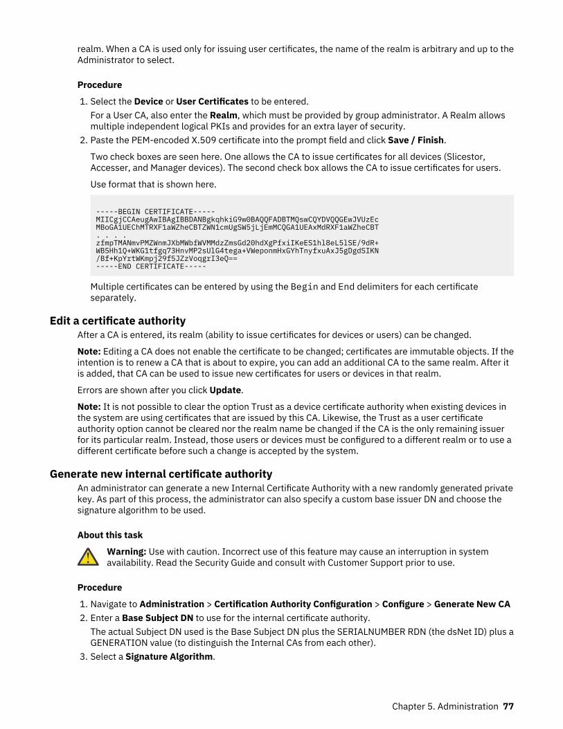
realm. When a CA is used only for issuing user certificates, the name of the realm is arbitrary and up to theAdministrator to select.
Procedure
1. Select the Device or User Certificates to be entered.For a User CA, also enter the Realm, which must be provided by group administrator. A Realm allowsmultiple independent logical PKIs and provides for an extra layer of security.
2. Paste the PEM-encoded X.509 certificate into the prompt field and click Save / Finish.
Two check boxes are seen here. One allows the CA to issue certificates for all devices (Slicestor,Accesser, and Manager devices). The second check box allows the CA to issue certificates for users.
Use format that is shown here.
-----BEGIN CERTIFICATE-----MIICgjCCAeugAwIBAgIBBDANBgkqhkiG9w0BAQQFADBTMQswCQYDVQQGEwJVUzEcMBoGA1UEChMTRXF1aWZheCBTZWN1cmUgSW5jLjEmMCQGA1UEAxMdRXF1aWZheCBT. . . .zfmpTMANmvPMZWnmJXbMWbfWVMMdzZmsGd20hdXgPfxiIKeES1hl8eL5lSE/9dR+WB5Hh1Q+WKG1tfgq73HnvMP2sUlG4tega+VWeponmHxGYhTnyfxuAxJ5gDgdSIKN/Bf+KpYrtWKmpj29f5JZzVoqgrI3eQ==-----END CERTIFICATE-----
Multiple certificates can be entered by using the Begin and End delimiters for each certificateseparately.
Edit a certificate authorityAfter a CA is entered, its realm (ability to issue certificates for devices or users) can be changed.
Note: Editing a CA does not enable the certificate to be changed; certificates are immutable objects. If theintention is to renew a CA that is about to expire, you can add an additional CA to the same realm. After itis added, that CA can be used to issue new certificates for users or devices in that realm.
Errors are shown after you click Update.
Note: It is not possible to clear the option Trust as a device certificate authority when existing devices inthe system are using certificates that are issued by this CA. Likewise, the Trust as a user certificateauthority option cannot be cleared nor the realm name be changed if the CA is the only remaining issuerfor its particular realm. Instead, those users or devices must be configured to a different realm or to use adifferent certificate before such a change is accepted by the system.
Generate new internal certificate authorityAn administrator can generate a new Internal Certificate Authority with a new randomly generated privatekey. As part of this process, the administrator can also specify a custom base issuer DN and choose thesignature algorithm to be used.
About this task
Warning: Use with caution. Incorrect use of this feature may cause an interruption in systemavailability. Read the Security Guide and consult with Customer Support prior to use.
Procedure
1. Navigate to Administration > Certification Authority Configuration > Configure > Generate New CA2. Enter a Base Subject DN to use for the internal certificate authority.
The actual Subject DN used is the Base Subject DN plus the SERIALNUMBER RDN (the dsNet ID) plus aGENERATION value (to distinguish the Internal CAs from each other).
3. Select a Signature Algorithm.
Chapter 5. Administration 77
Options are: SHA512WithRSA (default), SHA384WithRSA, SHA256WithRSA, and SHA224WithRSA.The signature algorithm used on the CA certificate will match the signature algorithm which is used onits issued device certificates.
4. Click Generate.
Note: When generating the Internal CA, the Authority Key Identifier and Subject Key Identifierextensions are included to help TLS clients build certificate chains more efficiently. These extensionsare included in CAs generated on the 3.14.9 release and above as well as any device certificatesissued by those CAs. Any internal CA generated on an earlier release of the software did not havethese extensions and will remain unchanged.
Delete a certificate authorityClick Delete on the Certificate Authority Configuration page to delete a CA.
CAUTION: The same restrictions that apply to editing a CA apply to deleting one. If a certificateauthority is associated with any user or device in the system, it cannot be deleted or untrusted.Before you delete or untrust a user certificate authority, confirm that no accounts are associatedwith that CA on the Security tab. Similarly, to delete or untrust a device certificate authority,confirm that no devices are associated with that CA.
Revoke a certificate authorityThe Manager supports both Online Certificate Status Protocol (OCSP) and dynamic Certificate RevocationLists (CRL) as mechanisms to determine whether a signed and otherwise valid client certificate isrevoked.
OCSP is an online protocol for doing revocation checking of a single certificate at a time. Conceptually,upon receiving the client certificate as part of the SSL handshake, the Manager determines the OCSPresponder URL from the certificate and then query the target OCSP Responder to ask "is this certificaterevoked?", to which the OCSP responder responds with either a "yes" or "no".
CRLs are typically published once per day or once per week by the certificate authority. When theManager receives a client certificate as part of an SSL handshake, it determines the CRL distributionpoint's URL from the certificate and downloads the CRL from the URL. The CRL contains a list of all therevoked certificates and the manager checks to see whether the current client certificate is in this list. Ifthe certificate is found to be within that CRL, then validation of the certificate fails. It can take up to 1 hourbefore revoked certificate information is available in the Manager.
Note: This check occurs during the initial handshake of the TLS connection setup or authentication. If thecertificate is revoked later during the life of the connection, this revocation is not detected. However, ifyou configured the Accesser application library to use TLS, and devices are configured to use TLS foroutgoing connections via the configuration option within the Manager, then for the life of the TLSconnection, the certificate revocation list is retrieved on a periodic basis and the certificate of the remoteparty is revalidated. If the other party's certificate is found to be revoked, then the TLS connection isdisconnected.
The main advantage of OCSP over CRL is in the efficiency of being to get the status of a single certificateat a time. For PKI systems that contain many revoked certificates, the size of a CRL can grow largeresulting in inefficiencies when it comes to transferring over the network, holding in memory, or iteratingthrough to determine whether a certificate is in the list of revoked certificates.
Both OCSP and CRL are supported for users who are logged in to the Manager UI / API. The AccesserHTTPS interface supports client certificate authentication as well, but is not a standard authenticationmechanism in either S3 or OpenStack. The Accesser HTTPS interface supports revocation checks that useCRLs but does not support OCSP.
Note: OCSP Stapling is not supported in the current implementation.
78 IBM Cloud Object Storage System™ : Manager Administration Guide
Supply external certificates to IBM Cloud Object Storage System™ devicesOnce custom CAs are configured for use, each device can either be given a certificate by one of these CAsor continue to use the internal CA.
Use these three steps to configuring a device to use an externally generated certificate:
1. The device must be approved through the Manager Web Interface to accept it into the system.2. The CSR from the device must be extracted from the Manager Web Interface and sent to a CA.3. The resulting PEM-encoded certificate for that device must be entered into the Manager Web
Interface.
Accepting a device into the system can be accomplished from the home page. Devices pending approvalsinto the system appear in the Event Console.
Once they are approved into the system, the CSR can be extracted by either of the following methods:
• Click Configure > on the device's page.• Use the Bulk Device Certificate Configuration feature, which becomes available on the Configure tab
after a CA is configured for issuing device certificates.
Configuring a single device certificateTo access the CSR by the first method, follow these steps.
Procedure
1. I2. From the Configure tab, click Devices in the navigation panel.3. Select the device.4. Click Change for the Signed Device Certificate section at the bottom of the page.
What to do next
After Change is clicked, the CSR is displayed in a manner that enables it to be copied out of the ManagerWeb Interface and submitted to a CA. The certificate that is issued by the CA must contain the CommonName (CN) field of the Subject Distinguished Name and the content of the Subject Alternative Name asindicated in the CSR.
These parameters are validated by the Manager Web Interface when the certificate is pasted back intothe interface. Once updated, the certificate is published to the device and uses it. Another restriction isthat if the external CA sets the key usage field of the device certificate, then both SSL_CLIENT andSSL_SERVER key usage fields must be set.
Note: When pasting a certificate chain rather than a single certificate, all certificates up to, but notnecessarily including, a configured CA must be included. If unspecified intermediate CAs are involved inissuing the certificate, and they are not included, the input fails.
Note: If you want to change from an external certificate to a signed internal device certificate, delete allcertificate contents within the text box on the Edit Device Certificate page and click Update.
Configure multiple device certificatesThe second option for exporting CSRs and importing certificates is useful for handling many devices. Toaccess this option, click Configure next to Bulk Device Certificate Configuration on the Configure tab.
The page provides various options for selecting devices of interest, such as devices that do not yet have acertificate, or devices with certificates that are about to expire. Further refinement of selected devices ispossibly by checking or clearing each device by using the adjacent check box. Below the check boxes arethe CSRs for each of the selected devices. Hovering over a CSR causes a tooltip to display the host namewith which the device the CSR is associated. By highlighting all of the CSRs available, they can be copiedat once and submitted to a CA.
At the bottom of the page is an input field for entering device certificates.
Chapter 5. Administration 79

Note:
The certificates can be entered in any order; certificates are automatically correlated with the appropriateCSR by comparing the public key in the certificate to the public key in the CSR.
Entering certificates through this form enables all issued certificates to be imported into the Manager in asingle step.
It can take up to 1 hour before revoked certificate information is available in the Manager.
Configure Network Transport LayerEnable Transport Layer Security (TLS) for data communications.
When TLS is enabled, communication between Accesser and Slicestor devices use this mechanism. ClickConfigure from the TLS Configuration action bar on the Administration page. The following options arepresented.
Table 10. TLS options
Option Description
None Disables TLS
Integrity Enables authentication and integrity features of TLS.
Encryption Enables authentication, integrity, and confidentiality features.
Select None, Integrity, or Encryption and then click Update to disable or use cryptographic protocols fordata communications between the Accesser devices and the Slicestor devices. It is a system-widefeature, applicable to all vaults on this system.
If confidentiality is not wanted, selecting Integrity has a positive impact on performance.
TLS typically provides three features: Confidentiality (others cannot read the content), Authentication(you are communicating with whom you think you are), and Integrity (others cannot tamper withcommunications without being noticed). The Integrity option provides only authentication and integrity,providing improved performance in cases where confidentiality is not needed. The Encryption optionprovides all three features. If TLS is enabled, Cloud Object Storage Accesser devices establish encryptedconnections before they store and retrieving data from Cloud Object Storage Slicestor devices [1]. CloudObject Storage Slicestor devices establish encrypted connections to other Cloud Object Storage Slicestordevices while they perform data consistency scans and rebuilding.
The SecureSlice feature, although technically not encryption, guarantees that without access to athreshold number of slices, no information can be obtained without brute forcing the random symmetrickey that is used to perform the transformation. SecureSlice should remain enabled [default] for mostdeployments as it provides data at rest protection and has minimal performance impact.
Note: TLS encryption might affect data throughput performance. It should be disabled unless encryptionand added security are needed.
These items are independent of the TLS setting.
• Communication with the Cloud Object Storage Manager is always encrypted by using HTTPS, SSLtunneling, and SNMPv3 data protection.
• User passwords are always encrypted before transmission between any IBM devices. A user passwordis never sent in plaintext. [2]
• The Simple Object over HTTP (SOH) interface supports access over HTTP (plaintext) or HTTPS(encrypted). The HTTPS option is always made available for clients that are configured to use the properport.
• Software clients that are developed with the DSAF Server SecureSlice can always establish encryptedconnections. Such client applications might not acknowledge the TLS setting and should be designed toallow the user to configure separately whether TLS is used.
80 IBM Cloud Object Storage System™ : Manager Administration Guide
[1]Communication between clients and Cloud Object Storage Accessers devices is governed separately.With SOH, the client determines whether encryption is used. The Cloud Object Storage Accesser devicedoes not support IPSec.
[2]User passwords can be sent over plaintext between a client and an Accesser device over SOH whenHTTP (port 80, plaintext) is used. Clients can be configured to avoid it by using HTTPS (port 443,encrypted).
Configure Client Connection mode
Configure how the IBM Cloud Object Storage Client connects to the Accesser device, for IP accesscontrol. IBM COS enforces client IP access control on a standard vault or a container, according to belowconnection types.
Table 11. Configure Client Connection mode options
Option Description
Direct When Direct is selected, client is expected to directly connect to the access enableddevice. System uses TCP source IP for IP access control.
Proxy When Proxy is selected, client can connect to the accesser device through a load balanceror proxy. System uses HTTP Forward in this case. Customer with the proxy clientconnection must set the rightmost proxy ip address in the “x-forwarded-for” as the clientoriginating ip to use the Container IP whitelisting.
Configure drive healthConfigure disk health thresholds for Slicestor models. The health icon for each Slicestor Node changes asthresholds are met. Meeting the warning threshold changes the device health icon to yellow. If thenumber of drives meets or exceeds the error threshold, the icon changes to red. Messages are also sentto the Event Console. The Slicestor Node continues to function at reduced capacity until the disks arereplaced.
In the Administration tab, click Configure on the Drive Health Configuration action bar. Then, clickEnable to configure drive health thresholds for individual Slicestor Nodes.
For a multi-node Slicestor Node configuration, the disk health thresholds can be set for all nodes orcustomized on a per node basis. When you have two separate multi-node devices with 2 and 3 nodeconfigurations, setting the thresholds on the two node device and three node device sets thosethresholds for all nodes in that configuration. In addition, it is possible to set the disk health thresholdsfor each node separately, similar to any other Slicestor Node.
Configure maximum Accesser devices offlineSet the maximum percentage of Accesser devices at an Access Pool level, taking into account Sites, thatcan be unhealthy while executing maintenance operations such as Upgrade.
About this task
The administrator sets a maximum percentage of Accesser devices at an Access Pool level, taking intoaccount Sites, that can be unhealthy while executing maintenance operations like upgrade. The systemwill attempt to upgrade as many Accesser devices in an Access Pool as possible, but the percentage ofAccesser devices that are unhealthy or upgrading will not exceed the specified percentage of devices perAccess Pool and per Site.
Warning: Setting Maximum Accesser Devices Offline at percentages above 50% is notrecommended, and may result in availability issues.
Chapter 5. Administration 81
Procedure
1. Using the Manager, from the main menu, click the Administration tab.2. Click Configure on the Maximum Accesser Device Offline action bar.3. To set the system default percentage of Access devices that may be offline across all Access Pools
and Sites within the system, click Change on the Maximum Accesser Devices Offline Default actionbar.
• Select either One Accesser device offline at a time or enter the percentage using either the drop-down selector or text input.
• Click Update.4. To set the percentage of Access devices that may be offline for specific Storage Pools, select the
desired Storage Pools and click Change in the Storage Pool Settings action bar.
• Select either System Default, One Accesser device offline at a time or enter the percentage usingeither the drop-down selector or text input.
• Click Update.
Results
Note: When selecting Storage Pools, all Storage Pools sharing at least one Access Pool with the selectedStorage Pool will automatically be selected as well. The Maximum Accesser Devices Offline percentagewill be applied to all shared Access Pools.
Edit default maximum Accesser devices offlineThe administrator sets a default maximum percentage of Accesser devices at an Access Pool level, takinginto account Sites, that can be unhealthy while executing maintenance operations such as Upgrade.
About this task
Warning: Setting the Maximum Accesser Devices Offline at percentages above 50% is notrecommended, and may result in availability issues.
Procedure
1. Select either One Accesser device offline at a time or enter the desired percentage using either thedrop-down selector or text input.
2. Click Update
Edit maximum Accesser devices offlineThe administrator sets a maximum percentage of Accesser devices at an Access Pool level, taking intoaccount Sites, that can be unhealthy while executing maintenance operations such as Upgrade.
About this task
Warning: Setting the Maximum Accesser Devices Offline at percentages above 50% is notrecommended, and may result in availability issues.
Procedure
1. Select either System Default, One Accesser device offline at a time or enter the desired percentageusing either the drop-down selector or text input.
2. Click Update
82 IBM Cloud Object Storage System™ : Manager Administration Guide
Results
Note: When selecting Storage Pools, all Storage Pools sharing at least one Access Pool with the selectedStorage Pool will automatically be selected as well. The Maximum Accesser Devices Offline percentagewill be applied to all shared Access Pools.
Configure system ownerOn the Administration tab, click Configure on the System Owner action bar to configure ownerinformation. Provide general and contact information. Only the Name is required. This content is used bythe System Usage and Configuration Summary Report.
Configure SNMPSNMP v2c can be enabled for each of the device types in the system. Enabling allows polling of anyselected devices from all of the provided IP addresses. This feature allows numerous statistics to becollected by a third-party application. The following check boxes and fields are available:
Table 12. SNMP fields
Field Description
Enable SNMP Checking this box enables SNMP collection.
Manager, Accesser Devices, Slicestor Devices, FileAccesser Devices
Select the device types for polling.
Community String Configure the community string (for example,public).
IP Addresses/Subnets Identify the IP addresses/subnets used for polling.If the IP addresses field is left blank, IP access isopen, and any IP address can poll the selecteddevices. IP addresses can be separated by a spaceor comma.
Version Specifies whether SNMPv2c or SNMPv3 will besupported.
Security Level Specifies the security level of generated traps orinforms.
Username Specifies the username of the USM user.
Authentication Protocol Specifies the authentication protocol of the USMuser.
Authentication Password Specifies the authentication password of the USMuser.
Privacy Protocol Specifies the privacy protocol of the USM user.
Privacy Password Specifies the privacy password of the USM user.
Note: COS devices use the key extension algorithm defined in draft-blumenthal-aes-usm-04 whenAES256 encyption is selected. Your SNMP manager may use the Reeder algorithm, defined in draft-reeder-snmpv3-usm-3desede-00, to extend keys to the required length. To poll devices or receive alertsusing the Reeder algorithm, please select AES256With3DES. Refer to your SNMP manager’sdocumentation to determine which algorithm is required by your manager.
Changes that are made take a few minutes to take effect on each selected device.
Chapter 5. Administration 83
Configure Device Level APIEnable Device Level API to configure statistic and health APIs on devices for third-party applications.Select the device type: Manager, Accesser Devices, Slicestor Devices, File Accesser Devices, and SMCDevicesand File Accesser Devices. Two new device-level APIs are available to access health and statisticscontent.
Note: For more information, see the Device API Developer Guide.
Configure preferencesThese Manager Web Interface global settings can be changed and are seen by all users.
Table 13. Global settings
Parameter Default Description
Time Zone Greenwich Mean Time(GMT)
The drop-down allows a different time zone to beselected. Time zones for individual accounts canbe set on the Security tab.
Note: The backup schedule uses this time zone.
Device Display Alias This setting applies only to the UI. All files that areexported have both host names and alias fields.
Display Name Text value is displayed in the upper right corner ofthe Manager Web Interface.
Storage Units SI units In SI units, 1,000 Bytes equal 1 KB. Can bechanged to IEC units where 1,024 Bytes equal onekibibyte.
Session Timeout 30 minutes The drop-down allows range 5 minutes from 8hours.
Automatic Logout Disabled When Automatic Logout is enabled, a pop-upwindow appears when the session is about aminute from expiring and gives the user the optionto continue the session or to log out. Pages in theMonitor tab do not reload every 5 minutes.
When Automatic Logout is disabled, pages in theMonitor tab will reload every five minutes.
Note: When Automatic Logout is enabled, avoidopening the Manager Web Interface in more thanone browser tab. Because the focused tab usesmore processing power than unfocused tabs, thecountdown to session timeout can differ by a fewseconds between tabs.
Configure custom login bannerThrough the Administration tab, a user can configure a login banner.
Custom login text can be entered, with a maximum of 64,000 characters and no constraints on the type ofcharacters. The login banner displays on devices before SSH login.
Note:
Some SSH clients might not display the login banner under certain configurations, even if the server ispresenting one.
84 IBM Cloud Object Storage System™ : Manager Administration Guide
If you are using OpenSSH, setting LogLevel to QUIET, FATAL, or ERROR suppresses the banner.
You must set LogLevel to an option at least as verbose as INFO (which is the default, if unspecified) forthe banner to be displayed.
For other SSH clients, refer to their documentation if they are not displaying the banner.
When configured, the user-provided banner appears on the login page.
Configuring system propertiesAdvanced System Properties may be adjusted for system behavior.
About this task
Attention: These options allow modification to the internal operation of the system software andmust be used with caution and under the guidance of technical support.
Procedure
1. Click Configure on the System Properties Configuration title bar to open the Edit System Propertiespage.
2. Edit the values that you want to change.a) Change the Automatic Shutdown Timeout value to modify the system process to forcefully
terminate after the selected timeout period.
By default, the system process waits indefinitely for transactions to close on Slicestor devices andAccesser devices when requested to stop. Select one of the following values from the ChangeTimeout drop-down menu.
Attention: When you change this value, data being written may be lost.
• 15 minutes• 30 minutes• 1 hour• 2 hours• 4 hours• 8 hours• 16 hours
b) Change how long the system waits before reporting certain incidents.
Device timers trigger when certain conditions are detected, when a corresponding incident isopened, or both.
• Clear the default value to unlock the value slider.• Change the Processes Not Running value (Default: 3 minutes, Range: 3 - 60 minutes). This timer
determines the "hysteresis count" for generating process down incidents. This is measured inpolling cycles internally which roughly translates to minutes for a user (unless the polling cycle ismodified).
• Change the Slicestor Unresponsiveness value (Default: 30 minutes, Range: 3 - 60 minutes). Thistimer determines the "hysteresis count" for generating Slicestor device unresponsivenessincidents. This is measured in polling cycles internally which should roughly translate to minutesfor a user (unless the polling cycle is modified).
• Change the NTP Sync value (Default: 120 minutes, Range: 3 - 180 minutes). This timerdetermines the "hysteresis count" for generating NTP sync incidents. This threshold is for syncingwith NTP server(s) configured in /etc/ntp.conf (NOT the event for when the local clock is not
Chapter 5. Administration 85
synced with the Manager clock). This is measured in polling cycles internally which shouldroughly translate to minutes for a user (unless the polling cycle is modified).
• Change the Rebuilder Agent Hung value (Default: 1 hour, Range: 1 - 24 hours). This timerdetermines the amount of time the rebuilder agent waits before sending an event which opens anincident.
c) Set the default destination rate limit for reallocation, which can be limited to minimize impact onI/O performance. (Default: 20 MB/s.
1) Clear the check box to disable rate limiting by default.2) Change the default rate limit value.
d) Set whether the Accesser Application enforces vault quotas. (Default: Disabled.)
1) Select the check box to enable the Accesser Application to retrieve information from theManager to enforce vault quotas.
Note: This allows anonymous access to two APIs containing potentially sensitive information.e) Enable protection against cross-site request forgery attacks. (Default: Disabled.)
For more information, see “Enabling Cross Site Request Forgery protection” on page 86.f) Select the preferred IP family.
This setting prioritizes which family of IP address to use when establishing connections in thesystem. The preferred IP type is be attempted first, and if it fails, it falls back to the alternate IPtype address. This preference only applies for devices setup with dual stack addresses. For singlestack devices, IPv6 or IPv4, the preference has no effect and uses the one address available on thedevice.
Note: IPv6 is available for ClevSO 3.10.1 and newer. Once the system has been upgraded, devicescan be configured to use IPv6 stack in single or dual stack mode.
1) IPv42) IPv6
g) Object Access: Select the preferred read access control for container or vault. (Default: Grant readaccess to all objects in the container or vault, and grant list access to the container or vault.)
1) This option grants read access to all objects and grant list access to the container or vault.2) This option is more restricted, and grants ONLY list access to the container or vault.
h) Set the Slicestor Storage Engine: The storage engine is set on newly added Slicestor devices onceapproved. Changing the storage engine has no impact on existing Slicestor devices. (Default:Packed)
1) This option is the System Default (Packed).2) This option is Custom, and sets the Slicestor Storage Engine to File or Packed .
3. Determine which action you want to take:
• Click Update to apply the changes.• Click Cancel to leave the Properties untouched.
Enabling Cross Site Request Forgery protectionThe Manager can protect against Cross Site Request Forgery attacks. This protection is disabled bydefault.
About this task
When enabled, all POST requests from forms in the Manager Web Interface use a double-submittechnique. The web browser submits a randomly generated CSRF token to the Manager as both a hiddenform input and as a cookie. Then, the Manager application verifies that these two values are equal. Thisensures that requests are being processed only from users interacting with the Manager Web Interface
86 IBM Cloud Object Storage System™ : Manager Administration Guide
and not as the result of an attacker auto-submitting forms from a malicious third-party website withoutthe user's knowledge or consent.
Note: CSRF Protection is only enabled for HTTP POST requests. HTTP GET requests are exempt fromCSRF Protection with no CSRF token needed.
Enabling CSRF Protection might interfere with existing workflows, which use the Manager REST API toissue POST requests because existing REST API clients would not be aware of the details of the new CSRFprotection feature. For systems that would be impacted by this change in behavior, several options areavailable:
1. Do not enable CSRF Protection. It is disabled by default. Any new or upgraded system is not impactedin any way when an administrator never enables this feature on the manager.
2. When enabling CSRF Protection, you can also enable the bypass option with settings relevant to yourworkflow.
• If the CSRF Protection Bypass Header Name is set to "Authorization", any incoming requests thatcontain HTTP Basic Authorization credentials are exempted from CSRF Protection enforcement.
• If the REST API clients have a known request header that can distinguish them from a browserrequest, configure this header as the exemption rule. Set CSRF Protection Bypass Header Name to"User-Agent" and set CSRF Protection Bypass Header Value to "curl/.+" to allow requests to bemade from curl by using its default user agent header.
• Add a custom header to REST API client requests and then add an exemption for that header. Forexample, include the header "X-My-Header: <any value>" in all requests and then set the CSRFProtection Bypass Header Name to "X-My-Header".
3. Modify the API client to mimic the double-submit behavior of the Manager UI. Generate any value (theexact value is unimportant) and submit it both as a "csrfToken" request parameter and as a"csrfToken" cookie value.
To enable CSRF Protection, use the following procedure.
Procedure
1. Click the Administration tab.2. Click Configure in the System Properties Configuration section.3. Check the Enable CSRF Protection box in the CSRF Protection section.4. To allow bypass of CSRF Protection based on the presence of a specific HTTP request header, check
the corresponding box.a) Enter a CSRF Protection Bypass Header Name.b) Enter a CSRF Protection Bypass Header Value.
Configure advanced system settingsThis option allows detailed modification to the internals of the software and must be used with cautionand under the guidance of IBM Customer Support.
CAUTION: Contact IBM Support before you modify anything.
Configure advanced system properties.
1. Go to the Administration tab.2. Click Configure on the System Advanced Configuration action bar.3. Three subcategories appear on the System Advanced Configuration page.
• Detailed System Advanced Configuration• Selector-Based Advanced Configuration Rules• Existing Detailed Configuration Rules
Chapter 5. Administration 87
4. Enabling Detailed System Advanced Configuration presents administrators with an advancedconfiguration options box on the individual Edit Device, Edit Access Pool, and Edit Storage PoolPages.
To enable this option, check the Enable Detailed System Advanced Configuration check box.
1. Click Update.
Note: The Selector-Based Advanced Configuration Rules should be entered with the guidance of IBMCustomer Support. Configuration rules appear at the bottom of the page under the Existing DetailedConfiguration Rules section.
Configuring SSH keysConfigure device SSH authentication by choosing whether to require the current localadmin passwordwhen changing the password, adding SSH keys, ore removing SSH keys.
Procedure
1. Click the Security.2. In the Device SSH Authentication section, click Configure.
Configured keys are shown.The Device SSH Configuration page opens. The password requirement and any configured keys areshown.
3. In the Password Requirement section, click Change.4. Choose whether the current localadmin password is Required or Not Required when changing the
password and click Update.5. In the SSH Keys section, click Change.6. Click Add SSH Key.7. Paste a new SSH public key into the SSH Key field in OpenSSH ssh-rsa format.
You can add one or more keys at a time. Separate each key with a new line. Duplicate keys are notallowed.
For example, if you use ssh-keygen to generate your SSH key, the public key value is typicallycontained in the file at ~/.ssh/id_rsa.pub.
8. Click Update to add the SSH key.9. Click Remove to delete an existing key.
Configuring notificationsThe Notification Service generates a notification whenever an object is written, overwritten, or deletedusing the S3 protocol. The Notification Service utilizes a Producer to publish a stream of notifications to atopic. Each notification represents a single object-modifying event. You can then use a Consumer toconsume the object change records and take any necessary actions.
About this task
For more information on the Notification Service, see the Notification Service Feature DescriptionDocument.
Procedure
1. Click the Administration tab.2. In the Notification Service section, click Configure.3. On the Notification Service Summary page, click the name of an existing Notification Service to view
details.4. To create a new configuration, click Add.
88 IBM Cloud Object Storage System™ : Manager Administration Guide

5. In the General section, enter the following information:
• Name: The name of this Notification Service.• Topic: The name of the topic on the cluster that notifications will be sent to by default. This field is
optional.• Hostnames: A list of endpoints in host:port format. A single node cluster has a single entry, but
larger clusters could have multiple nodes.• Type: The type of Notification Service.
6. Optional: In the Authentication section, select Enable authentication. Enter yourNotification Serviceusername and password.
7. Optional: In the Encryption section, select Enable TLS for Notification Service network connections.a) If the cluster is encrypted using a self-signed TLS certificate, paste the root CA key for your
configuration in the Certificate PEM field.For more information, see "TLS encryption" in the Notification Service Feature Description Document.
8. Click Save.A banner appears on the Notification Service Summary page indicating that the Notification Servicewas created successfully and the configuration is listed in the Notification Service Summary table.
Editing or disabling a Notification ServiceModify the Notification Service's general, authentication, or encryption information and vault assignmentsor disable the Notification Service. The configuration settings are preserved while the Notification Serviceis disabled.
About this task
For more information on the Notification Service, see the Notification Service Feature DescriptionDocument.
Procedure
1. Click the Administration tab.2. In the Notification Service section, click Configure.3. In the Notification Service Summary table, click the name of the Notification Service you want to edit
or disable.4. Click Change.5. To modify the Notification Service:
a) Edit the information you want to change, then click Update.b) In the Assignments section, click Change.c) In the Assigned tab, select a vault or vaults and click Unassign from Notification Service to
remove those vaults from this configuration.The Not Assigned count updates to reflect the number of vaults you removed from the NotificationService.
d) In the Not Assigned tab, select a vault or vaults and click Assign to Notification Service to addthose vaults to this Notification Service.The Assigned count updates to reflect the number of vaults you added to the Notification Service.
6. To disable the configuration:a) Deselect Enable Notification Service.
A warning dialog box appears stating that disabling a Notification Service might cause applicationinconsistencies.
Chapter 5. Administration 89
Note: When a Notification Service is disabled, no notifications are sent and they are not queued upfor future reference. Any operations that occur after the Notification Service is disabled do notgenerate notifications.
b) Click OK.7. Click Update.
Deleting a Notification ServiceDeleting a Notification Service disassociates it from any assigned vaults, stopping notifications for thosevaults from that point on.
About this task
For more information on the Notification Service, see the Notification Service Feature DescriptionDocument.
Procedure
1. Click the Administration tab.2. In the Notification Service section, click Configure.3. In the Notification Service Summary table, click the name of the Notification Service you want to edit.4. Click Delete Notification Service.5. Enter your current password and click Delete.
A banner appears on the Notification Service Summary page indicating that the Notification Servicewas deleted successfully and the Notification Service is removed from the Notification ServiceSummary table.
Configure extended COS APIEnable the Resource Configuration API globally or on specific access pools so that end-users canconfigure IBM Cloud Object Storage resources. Select the features available in end-user API requests.
Configure Resource Configuration API
Before you beginThe Manager Web Interface can configure extended IBM Cloud Object Storage APIs settings. Currently, itsupports resource configuration API settings.
Procedure
1. Click the Administration tab.2. Click Configure from the Extended IBM Cloud Ibject Storage APIs action bar.
The Extended IBM Cloud Ibject Storage APIs page opens., and it displays an option to enable ordisable Resource Configuration API.
• Once enabled, it allows enable globally, or on specific access pools using the radio button.
– When resource configuration API is enabled globally, selected ports in API Settings are opened onall container mode access pools in the system. Also, selected ports by default open on all newlycreated container mode access pools.
– When resource configuration API is enabled on specific access pools, selected ports can only beenabled on selected access pools, access pools can be filtered based on the name or site itbelongs to.
• API SETTING
– Enable/disable ports to enable resource configuration API (select HTTP 8339 or HTTPS 8340). Atleast one port should be enabled when Resource Configuration API is enabled.
90 IBM Cloud Object Storage System™ : Manager Administration Guide
– Allow/Disallow configuring firewall rules for allowed IP addresses.3. Click Update.
Configuring Optimistic Status Reporting
About this task
Optimistic Status Reporting extends the period in which a device reports it's status to the IBM COSManager from 1 minute to 5 minutes. If devices detect an adverse condition, they will report to the IBMCOS Manager immediately.
Procedure
1. Click the Administration tab.2. Click Configure on the Optimistic Status Reporting action bar.3. Select or deselect Enable Optimistic Status Reporting.
Note: If there are devices not running a software version with Optimistic Status Reporting, they willnot report status immediately.
4. Click Update.
Chapter 5. Administration 91
Chapter 6. Monitoring the system
Monitoring the system, software, and hardware components helps to verify that tasks have completedsuccessfully. If a problem occurs during a lengthy operation, monitoring the task ensures quick detectionand resolution.
Monitored componentsThrough the monitoring application, reporting and notification of events and performance statistics areavailable.
The following components are reported:
• Vaults• Mirrors• Storage Pools• Access Pool• Sites• Drives• Devices
Note: When Automatic Logout is not enabled, these statistics are updated every 5 minutes, so a shortdelay in graphing happens after start. For more information, see “Configure preferences” on page 84.
Device health summaryThe overall health for each device is displayed on the Devices landing page. By selecting a particulardevice, a summary of its health is displayed with some additional details while in the Monitor page.
Devices that are up and functional have an icon in front of the device that appears green with an arrowthat is pointing up. This icon indicates that the Manager is able to communicate with the device and allcritical processes are running.
Devices in a critical state have a red icon with an "x" in it. This icon appears if the Manager cannotcommunicate with the device and one or more critical processes are not running. In some cases, a grayicon appears which means that this device is not polled. The letter to the left of the icon indicates thedevice type.
Device Health
The device health includes an overall summary, more details about the symbols, and associatedinterpretations.
In addition to the device health summary, the following details are provided: device ping time, SNMPresponse, checks for critical system processes that should be running on the device, and whether thesystem time is synchronized between the Manager and the device. (Time synchronization does not applyto Network Nodes.) Of these items, the SNMP response and critical system process checks directlycontribute to the device health. If either is red, then the device health appears red.
The small letter next to the device symbol indicates type: (A = Accesser Device; M = Manager; N =Network Node; S = Slicestor Device; F = File Accesser Device; C = SMC Device)
92 IBM Cloud Object Storage System™ : Manager Administration Guide
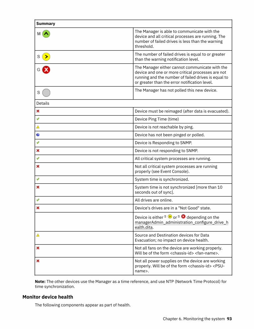
Summary
The Manager is able to communicate with thedevice and all critical processes are running. Thenumber of failed drives is less than the warningthreshold.
The number of failed drives is equal to or greaterthan the warning notification level.
The Manager either cannot communicate with thedevice and one or more critical processes are notrunning and the number of failed drives is equal toor greater than the error notification level.
The Manager has not polled this new device.
Details
Device must be reimaged (after data is evacuated).
Device Ping Time (time)
Device is not reachable by ping.
Device has not been pinged or polled.
Device is Responding to SNMP.
Device is not responding to SNMP.
All critical system processes are running.
Not all critical system processes are runningproperly (see Event Console).
System time is synchronized.
System time is not synchronized [more than 10seconds out of sync].
All drives are online.
Device's drives are in a "Not Good" state.
Device is either or depending on themanagerAdmin_administration_configure_drive_health.dita.
Source and Destination devices for DataEvacuation; no impact on device health.
Not all fans on the device are working properly.Will be of the form <chassis-id> <fan-name>.
Not all power supplies on the device are workingproperly. Will be of the form <chassis-id> <PSU-name>.
Note: The other devices use the Manager as a time reference, and use NTP (Network Time Protocol) fortime synchronization.
Monitor device healthThe following components appear as part of health.
Chapter 6. Monitoring the system 93

• Device ping time.• Device reporting status.• Critical system processes running.• System time is synced (devices other than the Manager).• Disk Online (Slicestor device specific).
The device icons for each item are as follows.
Table 14. Icons displayed in the Device Health Summary
Icon Detail
Device ping time.
Device is not reachable by ping.
Device is not pinged or polled.
All critical system processes are running.
Not all critical system processes are runningproperly. (Check the Event Console).
System time is synchronized.
System time is not synchronized (more than 10seconds out of sync).
All drives are online.
Monitor storage pool healthStorage Pool health status reports on storage pool, vault, and device health. Summaries for sites andstorage pools are shown as red, yellow, or green:
Table 15. Storage Pool health status
Status Detail
Green All vaults are healthy in the storage pool.
Yellow If any vault in the storage pool reports asdegraded, then the storage pool reports asdegraded.
Red If any vault in the storage pool reports as failed,then the storage pool reports as failed.
Note: In some circumstances, Slicestor devices in a Concentrated Dispersal storage pool can appear"red" because of disk errors, but the storage pool health appears "green" since the health of all vaults onthat pool are all "green."
94 IBM Cloud Object Storage System™ : Manager Administration Guide

Monitor vault healthVault health status reports on both vault health and device health for devices that are associated with thevault. Summaries for sites, pools, and vaults are shown as red, yellow, or green.
Vault Health
The number of available Slicestor® Devices1 isabove the alert level.
The number of available Slicestor® Devices1 isbetween the alert level and the write threshold.
The number of available Slicestor® Devices1 isbelow the write threshold.
1 For multiple Storage Pools, the threshold is calculated against the worse case pool.
In addition to the threshold indicators mentioned, separate icons indicate the status of the deployedAccesser® Device.
All deployed Accesser® Devices2 are available.
Some deployed Accesser® Devices2 are available.
No deployed Accesser® Devices2 are available.
2 Note that these status indicators do not take into account embedded Accesser service.
Monitor site healthSite Health is based on device availability.
Table 16. Monitor site health status
Status Detail
Site has all devices up.
Site has at least one device up and at least onedevice down.
Chapter 6. Monitoring the system 95
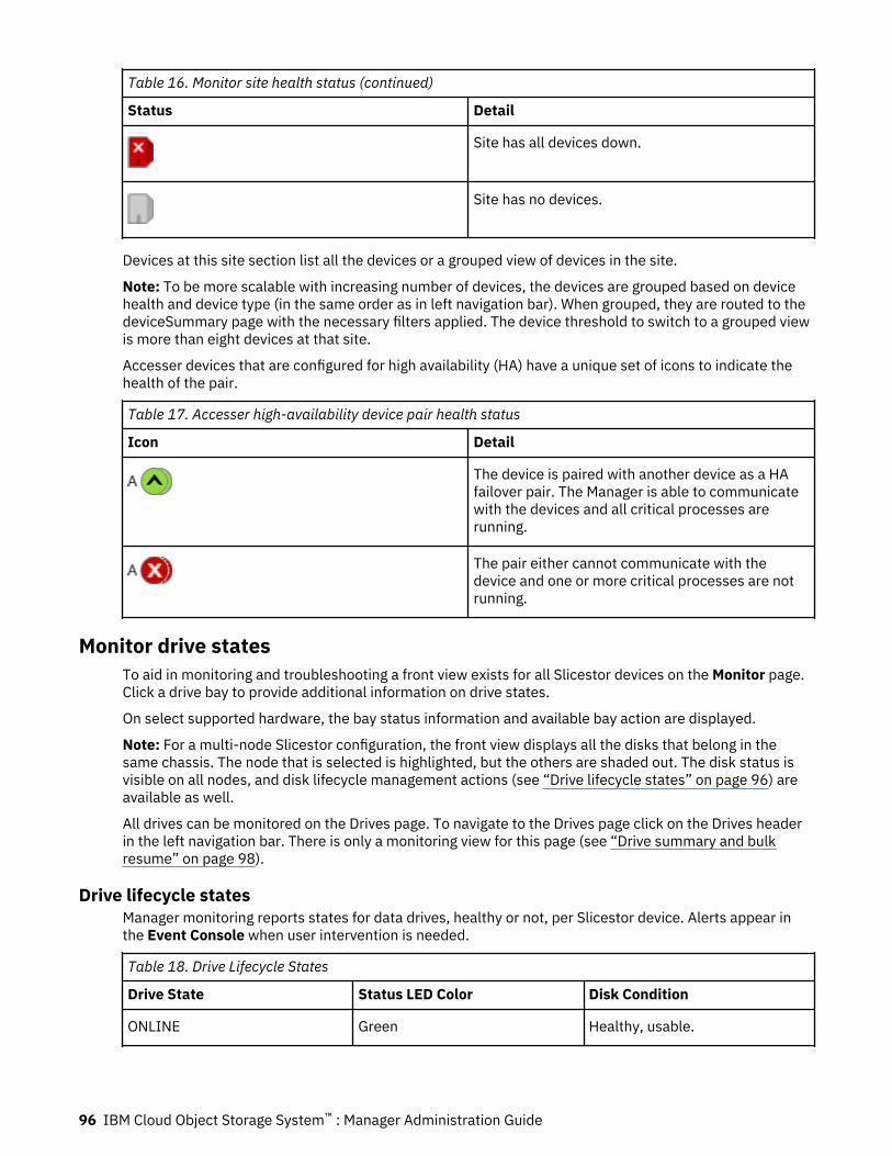
Table 16. Monitor site health status (continued)
Status Detail
Site has all devices down.
Site has no devices.
Devices at this site section list all the devices or a grouped view of devices in the site.
Note: To be more scalable with increasing number of devices, the devices are grouped based on devicehealth and device type (in the same order as in left navigation bar). When grouped, they are routed to thedeviceSummary page with the necessary filters applied. The device threshold to switch to a grouped viewis more than eight devices at that site.
Accesser devices that are configured for high availability (HA) have a unique set of icons to indicate thehealth of the pair.
Table 17. Accesser high-availability device pair health status
Icon Detail
The device is paired with another device as a HAfailover pair. The Manager is able to communicatewith the devices and all critical processes arerunning.
The pair either cannot communicate with thedevice and one or more critical processes are notrunning.
Monitor drive statesTo aid in monitoring and troubleshooting a front view exists for all Slicestor devices on the Monitor page.Click a drive bay to provide additional information on drive states.
On select supported hardware, the bay status information and available bay action are displayed.
Note: For a multi-node Slicestor configuration, the front view displays all the disks that belong in thesame chassis. The node that is selected is highlighted, but the others are shaded out. The disk status isvisible on all nodes, and disk lifecycle management actions (see “Drive lifecycle states” on page 96) areavailable as well.
All drives can be monitored on the Drives page. To navigate to the Drives page click on the Drives headerin the left navigation bar. There is only a monitoring view for this page (see “Drive summary and bulkresume” on page 98).
Drive lifecycle statesManager monitoring reports states for data drives, healthy or not, per Slicestor device. Alerts appear inthe Event Console when user intervention is needed.
Table 18. Drive Lifecycle States
Drive State Status LED Color Disk Condition
ONLINE Green Healthy, usable.
96 IBM Cloud Object Storage System™ : Manager Administration Guide
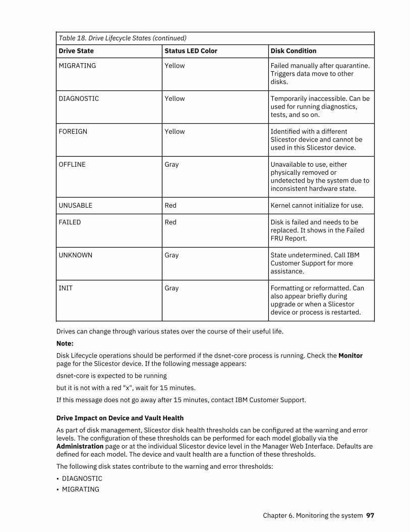
Table 18. Drive Lifecycle States (continued)
Drive State Status LED Color Disk Condition
MIGRATING Yellow Failed manually after quarantine.Triggers data move to otherdisks.
DIAGNOSTIC Yellow Temporarily inaccessible. Can beused for running diagnostics,tests, and so on.
FOREIGN Yellow Identified with a differentSlicestor device and cannot beused in this Slicestor device.
OFFLINE Gray Unavailable to use, eitherphysically removed orundetected by the system due toinconsistent hardware state.
UNUSABLE Red Kernel cannot initialize for use.
FAILED Red Disk is failed and needs to bereplaced. It shows in the FailedFRU Report.
UNKNOWN Gray State undetermined. Call IBMCustomer Support for moreassistance.
INIT Gray Formatting or reformatted. Canalso appear briefly duringupgrade or when a Slicestordevice or process is restarted.
Drives can change through various states over the course of their useful life.
Note:
Disk Lifecycle operations should be performed if the dsnet-core process is running. Check the Monitorpage for the Slicestor device. If the following message appears:
dsnet-core is expected to be running
but it is not with a red "x", wait for 15 minutes.
If this message does not go away after 15 minutes, contact IBM Customer Support.
Drive Impact on Device and Vault Health
As part of disk management, Slicestor disk health thresholds can be configured at the warning and errorlevels. The configuration of these thresholds can be performed for each model globally via theAdministration page or at the individual Slicestor device level in the Manager Web Interface. Defaults aredefined for each model. The device and vault health are a function of these thresholds.
The following disk states contribute to the warning and error thresholds:
• DIAGNOSTIC• MIGRATING
Chapter 6. Monitoring the system 97
• OFFLINE• FOREIGN• UNUSABLE
If the total number of non-healthy drives is greater than or equal to the warning threshold but less thanthe error threshold, the device health is set to yellow. If the total is greater than or equal to the errorthreshold, the device health is set to red.
Note: The vault health is affected if the error threshold is achieved.
Thus, the warning threshold does not impact the vault health.
With the aid of IBM Support, caching (1-wide) vaults can be created. The vaults are intended to be usedalong with a high reliability vault configuration within the same storage pool (although they can be used ina separate storage pool) for improving read performance. If the device health for a caching vault becomesred (due to disk failures or other issues), an incident appears stating the vault is unusable due to thenumber of accessible Slicestor devices that are falling below read/write threshold. Although data on theunhealthy drives is lost, it can still be obtained from the high reliability vault. Contact IBM CustomerSupport for more information, including reliability and performance tradeoffs.
Drive summary and bulk resumeAll drives can be monitored on the Drives page. To navigate to the Drives page click on the Drives headerin the left navigation bar. There is only a monitoring view for this page.
Storage Pool List
A list of Storage Pool names will be present in the upper left. Clicking on a Storage Pool requests all drivesfor the given Storage Pool. In addition to each pool is an option to view drives which are in any pool and anoption to view drives which are in no pool.
• Ordering
– Storage Pools are ordered based on the proportion of non-ONLINE drives in their worst Set. TheStorage pool with the highest proportion will be listed at the top and ranked #1. This list is sorted indescending order. If there is a tie between pools they will be sorted in alpha-numerical orderaccording to their name. If a pool has zero non-Online drives than a checkmark icon will be usedinstead of a number ranking. These pools are also sorted in alpha-numerical order.
• Counts
– Counts are located on the right side of the list. The header shows a count of the total number ofStorage Pools. Each row has a count of the total number of drives associated with the given pool orsuperset.
Visualization
A bar chart visualization will be present in the upper right. The drives shown on the bar chart correspondto the selected Storage Pool. Each bar will represent either each Set in the pool or each Storage Pool inthe system.
• Within each bar are different color coded stacks. Each color corresponds to a grouping of drive states.Groupings are defined in the legend.
• Hovering over each stack will render a popup. The popup will show the drive counts of each drive statein the grouping.
• By default all drive states will be shown. The hide online checkbox may be selected to hide drives in anonline state from the visualization.
Table
The table will contain specific drive information for drives in the selected pool.
98 IBM Cloud Object Storage System™ : Manager Administration Guide
• Optional Columns
– Drives have a large number of properties. To manage the table width only certain columns arerequired while the rest are simply optional. To enable an optional column click the columns iconabove the right side of the table. Selecting a column will append it to the table. Unselecting a columnwill remove it from the table. Certain optional columns are enabled by default.
• Filters
– Drives in the table can be filtered by Set and Diagnostic state. This can be done through selecting thefilters icon.
• Bulk Resuming Drives
– Before resuming drives the table must be filtered by Diagnostic state. Enabling this filter will add acheckbox column. To enable the Diagnostic state filter click the filter icon to the upper right of thetable.
– After filtering by Diagnostic drives may now be selected and resumed by clicking the resume button.
Drive lifecycle state descriptions and troubleshooting
ONLINEThe normal state that most disks are in for most of their life. This state indicates that the disk isfunctioning normally and that all data operations are supported on the disk.
INITThe disk state shows Initializing when the disk is formatting or reformatting. When complete, the diskchanges state to ONLINE unless a disk health issue is detected.
OFFLINEIf a disk is physically removed or undetected by the system due to inconsistent hardware state, its statechanges to OFFLINE. In an OFFLINE state, read and write operations to the disk are not supported.Missing slices that were written to the system while the disk was OFFLINE are rebuilt on the disk.
Recommended user remediation options
• Reinsert the OFFLINE disk.• Replace the OFFLINE disk with a new disk to trigger rebuild of slices on the new disk.• Leave the disk in an OFFLINE state. Use the dispose command on the Slicestor console or on the
Manager to ensure data reliability for the data slices on the OFFLINE disk.
Note: Other disks within the Slicestor device become responsible for slices on an OFFLINE disk. Areplacement disk cannot be used immediately. The Slicestor device starts using the new disk when theused space on other disks exceeds a system-defined threshold.
DIAGNOSTICA disk can change from an ONLINE state to a DIAGNOSTIC state if the application detects problems thatare related to disk performance or significant number of I/O errors. It can also change into this state if itfails a SMART test or SMART attributes fall below threshold. The purpose of the DIAGNOSTIC state is toallow the operator to investigate whether the disk needs to be replaced or if it is healthy enough toresume operation within the system.
In a DIAGNOSTIC state, read and write operations to the disk are not supported. Existing slices on thedisk are preserved indefinitely.
DIAGNOSTIC disks are considered "quarantined" and are occasionally referred to as so throughout thedocumentation.
Chapter 6. Monitoring the system 99
CAUTION: Leaving a disk as DIAGNOSTIC for an extended duration affects data reliability and isdiscouraged.
Recommended user remediation options
See Table 19 on page 100 for recommended user remediation options.
Note:
If multiple disks in the same Slicestor change to DIAGNOSTIC state at the same time, it can indicate abackplane, disk controller, or other component failure. Contact IBM Customer Support if it happens.
When a DIAGNOSTIC disk is pulled and reinserted, a new event appears.
Disk in drive bay X with S/N Y is diagnostic state, due to Z.
To find more details about the reason, go to Advanced Search in the Event Console and specify the diskserial number. Identify the corresponding quarantined disk event, which has the reason.
Diagnostic states and recovery actionsThe event on the UI indicates why the disk was placed into a DIAGNOSTIC (or in earlier releases,quarantined) state. Multiple reasons can exist for placing a disk into one of these states, but the softwarepresents only the first reason it detects.
The version of ClevOS that a device uses determines the event description that is displayed. Refer to thefollowing tables for the event descriptions specific to the version of ClevOS in use on the impacted device.
Note: Contact IBM Customer Support if the following situations occur:
• The drive does not change to an ONLINE (or in earlier releases, a good) state after you take therecommended actions in the following tables.
• The failure rate of data disks in a storage pool or set is higher than 4% AFR (Annual Failure Rate). SeeAFR Rate Calculation for details.
• Multiple data disks in a storage pool, set, or Slicestor® device fail in a coordinated fashion, which mightindicate a higher-order failure.
• The Event Console contains an event description not included in the following tables.
Include failed drive serial numbers and event description text (if applicable) with all RMA requests.
Table 19. ClevOS 3.10.1+ DIAGNOSTIC state recovery actions
Event Description Recommended Action
User initiated action. Resume the disk through the IBM COS Manager UI or by using theCLI command: # storage resume <disk-id>
Possible storage metadata issuesdetected.
1. Resume the disk through the IBM COS Manager UI or by using theCLI command: # storage resume <disk-id>
2. If the disk is not in an ONLINE state after it is resumed, thenfollow these steps:
a. If the storage pool or set that the disk is part of is less than95% used:
1) Fail the disk through the IBM COS Manager UI or by usingthe following CLI command: # storage fail <disk-id>
2) When the failing disk migration finishes, replace the disk.b. If the storage pool or set that the disk is part of is greater than
or equal to 95% used, replace the disk with a new disk.
I/O timeouts exceededthreshold.
100 IBM Cloud Object Storage System™ : Manager Administration Guide
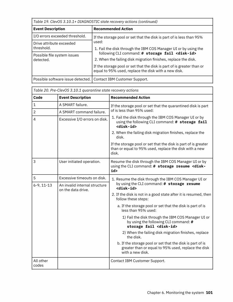
Table 19. ClevOS 3.10.1+ DIAGNOSTIC state recovery actions (continued)
Event Description Recommended Action
I/O errors exceeded threshold. If the storage pool or set that the disk is part of is less than 95%used:
1. Fail the disk through the IBM COS Manager UI or by using thefollowing CLI command: # storage fail <disk-id>
2. When the failing disk migration finishes, replace the disk.
If the storage pool or set that the disk is part of is greater than orequal to 95% used, replace the disk with a new disk.
Drive attribute exceededthreshold.
Possible file system issuesdetected.
Possible software issue detected. Contact IBM Customer Support.
Table 20. Pre-ClevOS 3.10.1 quarantine state recovery actions
Code Event Description Recommended Action
1 A SMART failure. If the storage pool or set that the quarantined disk is partof is less than 95% used:
1. Fail the disk through the IBM COS Manager UI or byusing the following CLI command: # storage fail<disk-id>
2. When the failing disk migration finishes, replace thedisk.
If the storage pool or set that the disk is part of is greaterthan or equal to 95% used, replace the disk with a newdisk.
2 A SMART command failure.
4 Excessive I/O errors on disk.
3 User initiated operation. Resume the disk through the IBM COS Manager UI or byusing the CLI command: # storage resume <disk-id>
5 Excessive timeouts on disk. 1. Resume the disk through the IBM COS Manager UI orby using the CLI command: # storage resume<disk-id>
2. If the disk is not in a good state after it is resumed, thenfollow these steps:
a. If the storage pool or set that the disk is part of isless than 95% used:
1) Fail the disk through the IBM COS Manager UI orby using the following CLI command: #storage fail <disk-id>
2) When the failing disk migration finishes, replacethe disk.
b. If the storage pool or set that the disk is part of isgreater than or equal to 95% used, replace the diskwith a new disk.
6-9, 11-13 An invalid internal structureon the data drive.
All othercodes
Contact IBM Customer Support.
Chapter 6. Monitoring the system 101
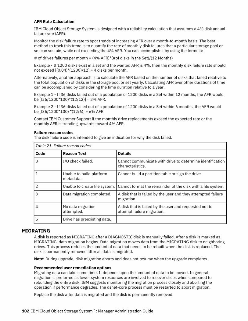
AFR Rate Calculation
IBM Cloud Object Storage System is designed with a reliability calculation that assumes a 4% disk annualfailure rate (AFR).
Monitor the disk failure rate to spot trends of increasing AFR over a month-to-month basis. The bestmethod to track this trend is to quantify the rate of monthly disk failures that a particular storage pool orset can sustain, while not exceeding the 4% AFR. You can accomplish it by using the formula:
# of drives failures per month = (4% AFR)*(#of disks in the Set)/(12 Months)
Example - If 1200 disks exist in a set and the wanted AFR is 4%, then the monthly disk failure rate shouldnot exceed [(0.04)*(1200)/12] = 4 disks per month.
Alternatively, another approach is to calculate the AFR based on the number of disks that failed relative tothe total population of disks in the storage pool or set yearly. Calculating AFR over other durations of timecan be accomplished by considering the time duration relative to a year.
Example 1 - If 36 disks failed out of a population of 1200 disks in a Set within 12 months, the AFR wouldbe [(36/1200*100)*(12/12)] = 3% AFR.
Example 2 - If 36 disks failed out of a population of 1200 disks in a Set within 6 months, the AFR wouldbe [(36/1200*100) *(12/6)] = 6% AFR.
Contact IBM Customer Support if the monthly drive replacements exceed the expected rate or themonthly AFR is trending upwards toward 4% AFR.
Failure reason codesThe disk failure code is intended to give an indication for why the disk failed.
Table 21. Failure reason codes
Code Reason Text Details
0 I/O check failed. Cannot communicate with drive to determine identificationcharacteristics.
1 Unable to build platformmetadata.
Cannot build a partition table or sign the drive.
2 Unable to create file system. Cannot format the remainder of the disk with a file system.
3 Data migration completed. A disk that is failed by the user and they attempted failuremigration.
4 No data migrationattempted.
A disk that is failed by the user and requested not toattempt failure migration.
5 Drive has preexisting data.
MIGRATINGA disk is reported as MIGRATING after a DIAGNOSTIC disk is manually failed. After a disk is marked asMIGRATING, data migration begins. Data migration moves data from the MIGRATING disk to neighboringdrives. This process reduces the amount of data that needs to be rebuilt when the disk is replaced. Thedisk is permanently removed after all data is migrated.
Note: During upgrade, disk migration aborts and does not resume when the upgrade completes.
Recommended user remediation optionsMigrating data can take some time. It depends upon the amount of data to be moved. In generalmigration is preferred as fewer system resources are involved to recover slices when compared torebuilding the entire disk. IBM suggests monitoring the migration process closely and aborting theoperation if performance degrades. The dsnet-core process must be restarted to abort migration.
Replace the disk after data is migrated and the disk is permanently removed.
102 IBM Cloud Object Storage System™ : Manager Administration Guide

To abort the migration process, do the following steps.
1. Go to the View from the Front.2. Click Stop Migration for the MIGRATING disk.3. When the Slicestor device comes back online, the disk is reported as FAILED and the disk can be
replaced.
Note: Contact IBM Customer Support for more guidance if you run into this issue.
UNUSABLEA disk can change to an UNUSABLE state if the OS fails to initialize the disk on startup or when the disk isinserted into the Slicestor device.
If a disk is in the UNUSABLE state, you can issue a password-protected Reset operation through theManager Web Interface that starts a disk reformat. The functionality is equivalent to the nut storagereset command.
A Reset action button is available for UNUSABLE disks in the physical disk layout. This action reformatsthe disk. The Operator role cannot perform this action. A password is needed to proceed with the resetoperation.
In an UNUSABLE state, any slices on the disk are inaccessible. When a disk changes from a DIAGNOSTICstate, the process of rebuilding missing slices is in progress on other disks.
Recommended user remediation options
• Replace the UNUSABLE disk with a good disk.• Attempt to Reset the disk under the following scenarios.
1. Insertion of a failed drive2. Insufficient initial drive state (for example, refurbished drive or incorrect factory initialization)
Note: Since other disks within the Slicestor device become responsible for slices on a pulled disk, areplacement disk cannot be used immediately. The Slicestor device starts using the new disk when theused space on other disks exceeds a system-defined threshold.
FOREIGNA disk can be reported as FOREIGN if it is removed from one Slicestor device and inadvertently placed in adifferent Slicestor device. I/O operations are not allowed on a FOREIGN disk.
If a disk is in the FOREIGN state, you can issue a password-protected Reset operation through theManager Web Interface that starts a disk reformat. The functionality is equivalent to the nut storagecommand.
A Reset action button is available for FOREIGN disks in the physical disk layout. This action reformats thedisk. The Operator role cannot perform this action. A password is needed to proceed with the resetoperation.
Reset FOREIGN disk
In the Event Console the messages appear in the following sequence.
• A disk was detected as FOREIGN.• An event is sent to the console that the disk was reset by the user who initiated the action.• After the disk is reset, it is reported as a new disk.
It is recommended to reset the disk as soon as possible to minimize the amount of rebuilding and protectthe overall data reliability.
Chapter 6. Monitoring the system 103
UNKNOWNUNKNOWN state is reported when the disk returns an unexpected message.
Note: The event can clear on its own. It is recommended to call IBM Customer Support to report theproblem.
When a disk is moved from UNKNOWN to ONLINE, the message in the Event Console is cleared. The viewfrom the front status color is also changed from gray to green.
RAID statesThe Manager separates RAID member states from the state of the entire array.
The RAID array health reports as OPTIMAL when all the disks are ONLINE.
The entire array is reported as DEGRADED when any RAID member is reported as OFFLINE.
A RAID member reports REBUILD when it is replaced. The incident for the entire array is only clearedwhen all RAID members report as ONLINE and when the array reports as OPTIMAL.
Event consoleIncidents are separate from other events. This area focuses attention on incidents - stateful events thatrequire operator intervention. The event content consists of two sections: Open Incidents, and EventConsole (event logs). The Event Console displays events based on context that is defined by filters thatare selected in Advanced Search (default time frame is the last two weeks).
Open incidentsThe Open Incidents section highlights events that require intervention. After the issue is resolved, theincident will close; most will close automatically.
In some cases, manual intervention might be needed by IBM Customer Support to close an incident.
The incidents are grouped under a corresponding Manager device, Storage Pool, or Access Pool. Eachincident group can be opened and closed by using the open/close icon. The incidents are also categorizedinto four types:
• System - Incidents that are related to the system as a whole. Examples include backup failures andSlicestor device to Slicestor device communication issues.
• Hardware - Incidents that are related to a specific device's hardware. Examples include high file systemusage, high CPU temperature, and power supply fail.
• Software - Incidents that are related to a specific device's software. Examples include processes notrunning and the device in an inconsistent state.
• Disk - Incidents that are related to Disk Lifecycle Management. Examples include when a disk isDIAGNOSTIC and when a disk is FAILED.
Each category has a corresponding filter at the top of the section. Clicking the check box shows/hides anyincidents that match the respective category.
In the following scenario, a disk is quarantined, pulled, permanently removed, disposed, Slicestor deviceis powered down, disk that is replaced, Slicestor device that is powered on, an incident that indicates:
Disk in drive bay 1 with S/N 9QJ1SRR5 is a previously removed disk will remain in the Open Incident view of the {mgr}.
Note: If all disk issues are addressed and a mis-match persists between disk states that are presented onthe Manager Web Interface disk diagram and the Open Incidents view, contact IBM Customer Support.Manual closing of disk incidents might be needed.
104 IBM Cloud Object Storage System™ : Manager Administration Guide

EventsWhen certain conditions are detected, events are generated and displayed in the Event Console, which isaccessible from both the Home and Monitor pages.
The console has a number of features to aid in troubleshooting and incident management. The displayedevents are context-specific; events can be displayed for the overall system and its components. Eventseverity is displayed as follows.
1. Critical2. Error3. Warning4. Info
Manager events include status information from all nodes in the system. Events are ordered by mostrecent.
Note: When you upgrade a device to ClevOS 3.10.1 or later, existing disk lifecycle management eventsbecome part of the incident state cycle. New events that are opened after upgrade are added to the oldstate cycle and indicate that the disk was previously quarantined.
Audits also appear in the Event Console. Audits are special events, which have no severity level, and areonly visible by users with the role of Super Admin, System Administrator, or Security Officer.
For audit messages, an empty string, denoted by '', indicates that the specified value is unset.
Event search
Event Console
The Event Console is similar to an event log and displays the most recent 50 events (most recent first),based on the context defined by the Current Filters. The Current Filters are selected via the AdvancedSearch (Pressing Advanced Search opens/closes the display). After the filters are selected, press Searchto view the corresponding events. The default context is a single filter that indicates a time range thatrepresents the last week. Selecting the “x” on a filter removes the filter and automatically initiates a newsearch, establishing a new context. Click Show Audits to include 30 days of audit information with theevents. Audits can be filtered via Advanced Search.
Click Show More to display more events in increments of 50. Use the Remove/Add scrollbar to hide/addback the inner scroll bar in the display.
Select Export to create a .csv (comma-separated values) file for use with spreadsheet applications. Theexport file, limited to the most recent 50000 events, contains all events, regardless of the severity filtersetting. Events can also be forwarded to an email account based on severity, frequency, and timing. Usethe Preference menu to configure this function to the wanted operation.
Note: A New Event Count (#) prefix is added to the HTML title tag in the browser when new events exist inthe Event Console. After the New Events link is selected, the count disappears until a new event occurs.
In Advanced Search, the Message text box accepts standard text or regular expressions (a specialpattern that specifies a set of strings - see http://en.wikipedia.org/wiki/Regular_expression for anoverview). When you use standard text (Regular expression box cleared), an “AND” search is done of theindividual terms that are provided in the text box. In particular, all terms in any order are returned whenthe regular expression box is not checked.
Alternatively, a search based on regular expressions can be initiated. It is accomplished by entering aregular expression in the Message text box, selecting the Regular expression box, and clickingSearch.Several examples of regular expressions are provided.
Table 22. Regular expression examples
“OR” functions. usage | space (matches eventswith usage or space).
Note - The vertical bar separatesalternatives.
Chapter 6. Monitoring the system 105
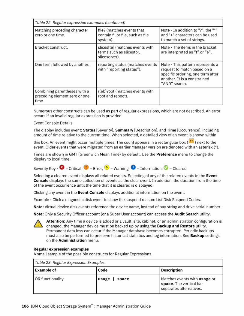
Table 22. Regular expression examples (continued)
Matching preceding characterzero or one time.
file? (matches events thatcontain fil or file, such as filesystem).
Note - In addition to "?", the "*"and "+" characters can be usedto match a set of strings.
Bracket construct. slices[te] (matches events withterms such as slicestor,sliceserver).
Note - The items in the bracketare interpreted as “t” or “e”.
One term followed by another. reporting status (matches eventswith “reporting status”).
Note - This pattern represents arequest to match based on aspecific ordering, one term afteranother. It is a constrained“AND” search.
Combining parentheses with apreceding element zero or onetime.
r(eb)?oot (matches events withroot and reboot).
Numerous other constructs can be used as part of regular expressions, which are not described. An erroroccurs if an invalid regular expression is provided.
Event Console Details
The display includes event: Status [Severity], Summary [Description], and Time [Occurrence], includingamount of time relative to the current time. When selected, a detailed view of an event is shown within
this box. An event might occur multiple times. The count appears in a rectangular box ( ) next to theevent. Older events that were migrated from an earlier Manager version are denoted with an asterisk (*).
Times are shown in GMT (Greenwich Mean Time) by default. Use the Preference menu to change thedisplay to local time.
Severity Key - = Critical, = Error, = Warning, = Information, = Cleared
Selecting a cleared event displays all related events. Selecting of any of the related events in the EventConsole displays the same collection of events as the clear event. In addition, the duration from the timeof the event occurrence until the time that it is cleared is displayed.
Clicking any event in the Event Console displays additional information on the event.
Example - Click a diagnostic disk event to show the suspend reason: List Disk Suspend Codes.
Note: Virtual device disk events reference the device name, instead of bay string and drive serial number.
Note: Only a Security Officer account (or a Super User account) can access the Audit Search utility.
Attention: Any time a device is added or a vault, site, cabinet, or an administration configuration ischanged, the Manager device must be backed up by using the Backup and Restore utility.Permanent data loss can occur if the Manager database becomes corrupted. Periodic backupsmust also be performed to preserve historical statistics and log information. See Backup settingson the Administration menu.
Regular expression examplesA small sample of the possible constructs for Regular Expressions.
Table 23. Regular Expression Examples
Example of Code Description
OR functionality usage | space Matches events with usage orspace. The vertical barseparates alternatives.
106 IBM Cloud Object Storage System™ : Manager Administration Guide
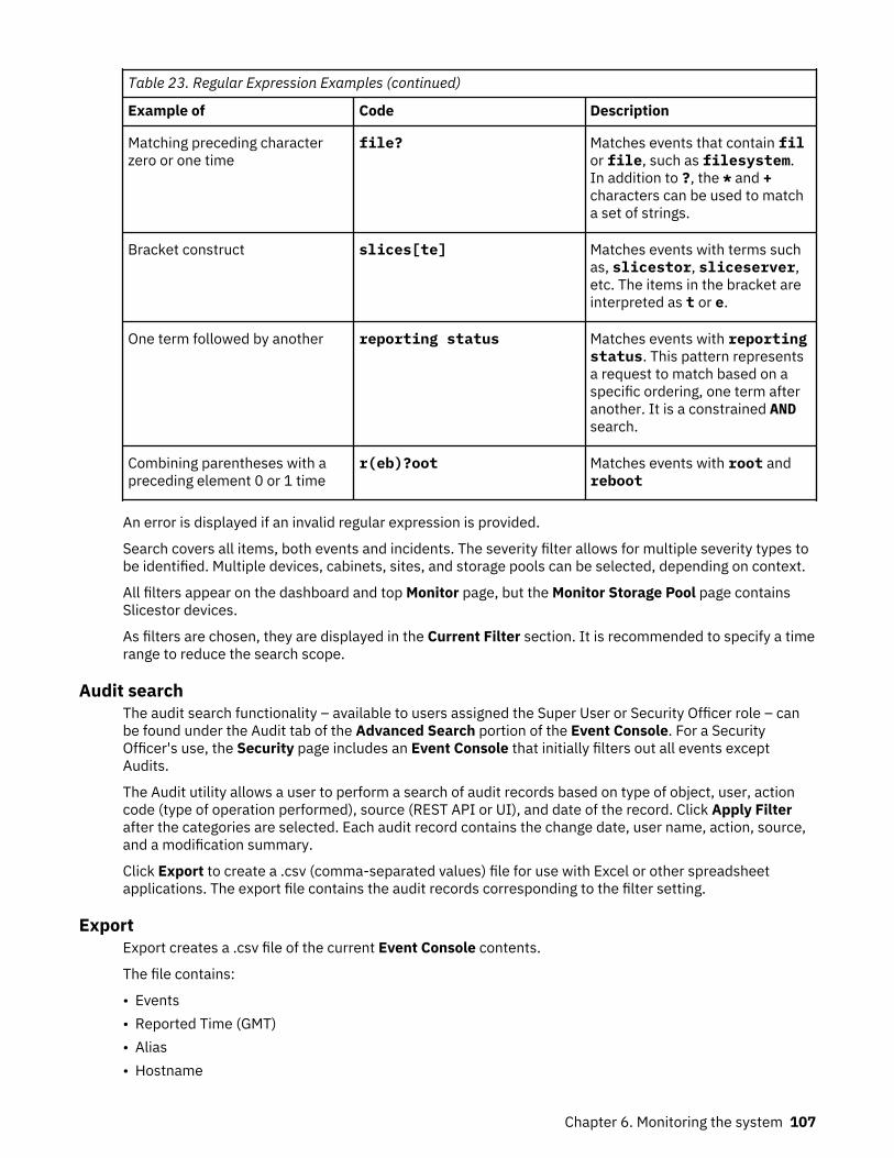
Table 23. Regular Expression Examples (continued)
Example of Code Description
Matching preceding characterzero or one time
file? Matches events that contain filor file, such as filesystem.In addition to ?, the * and +characters can be used to matcha set of strings.
Bracket construct slices[te] Matches events with terms suchas, slicestor, sliceserver,etc. The items in the bracket areinterpreted as t or e.
One term followed by another reporting status Matches events with reportingstatus. This pattern representsa request to match based on aspecific ordering, one term afteranother. It is a constrained ANDsearch.
Combining parentheses with apreceding element 0 or 1 time
r(eb)?oot Matches events with root andreboot
An error is displayed if an invalid regular expression is provided.
Search covers all items, both events and incidents. The severity filter allows for multiple severity types tobe identified. Multiple devices, cabinets, sites, and storage pools can be selected, depending on context.
All filters appear on the dashboard and top Monitor page, but the Monitor Storage Pool page containsSlicestor devices.
As filters are chosen, they are displayed in the Current Filter section. It is recommended to specify a timerange to reduce the search scope.
Audit searchThe audit search functionality – available to users assigned the Super User or Security Officer role – canbe found under the Audit tab of the Advanced Search portion of the Event Console. For a SecurityOfficer's use, the Security page includes an Event Console that initially filters out all events exceptAudits.
The Audit utility allows a user to perform a search of audit records based on type of object, user, actioncode (type of operation performed), source (REST API or UI), and date of the record. Click Apply Filterafter the categories are selected. Each audit record contains the change date, user name, action, source,and a modification summary.
Click Export to create a .csv (comma-separated values) file for use with Excel or other spreadsheetapplications. The export file contains the audit records corresponding to the filter setting.
ExportExport creates a .csv file of the current Event Console contents.
The file contains:
• Events• Reported Time (GMT)• Alias• Hostname
Chapter 6. Monitoring the system 107
• Type• IP• Site• Severity• Stream Type• Status• Summary• Audits• Change Date (GMT)• Account (Username)• Action• Source• Modification
Performance graphsPerformance graphs are available for devices and vaults. The graphs allow the user to view the systemover six default time ranges and also allow for custom time ranges to be entered.
To access the Device Graphs.
1. Click Monitor tab.2. Click Devices in the navigation panel.3. Select the wanted Devices tab. It generates the performance graphs.
To view graphs for an individual vault.
1. Click Monitor on the Summary section of the wanted vault. To get to the page, click Vaults in thenavigation panel and select the vault.
2. Performance graphs can be expanded or hidden; hidden is the default.
• Click the plus icon to expand the graph.• Click the minus icon on the graph's title to hide the graph.
Standard computer performance parameters are calculated by the device or collected via SNMP, lm-sensors, and so on, from its system board and system-specific information for the Accesser, and Slicestordevices. Axes for all graphs are scaled automatically depending upon the time selected. By default, six-hour graphs are shown. The time range can go from 5 minutes to yearly. The time frame can be selectedby the dropdown under the Performance action bar or by changing the To and From dates to anacceptable range.
Several basic capabilities exist to support further inspection and troubleshooting:
• Select the icon in the upper right corner of the graph to expand it.• Click Export to get data provided in .csv format. This data can be analyzed further by tools.• Click Share to get a link to the current page and time range.• Click the device or vault links to go directly to their pages. It is only available in some graphs, such as
Scanned Sources and the Outgoing/Incoming Rebuild.• Click Hide All or Show All to hide or show all lines.• Click the line in the legend to hide or show individual lines.• Click buttons that appear on hover to pan left or right through the data.• Click and drag on the graph to select a new time range to zoom into based on the range that is
represented in the highlighted section.
Vertical Crosshairs are synchronized across all graphs and can be set/unset by clicking any graph.
108 IBM Cloud Object Storage System™ : Manager Administration Guide
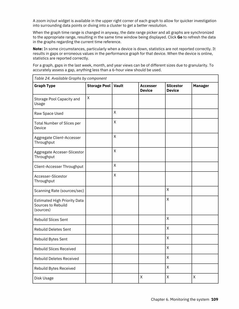
A zoom in/out widget is available in the upper right corner of each graph to allow for quicker investigationinto surrounding data points or diving into a cluster to get a better resolution.
When the graph time range is changed in anyway, the date range picker and all graphs are synchronizedto the appropriate range, resulting in the same time window being displayed. Click Go to refresh the datain the graphs regarding the current time reference.
Note: In some circumstances, particularly when a device is down, statistics are not reported correctly. Itresults in gaps or erroneous values in the performance graph for that device. When the device is online,statistics are reported correctly.
For a graph, gaps in the last week, month, and year views can be of different sizes due to granularity. Toaccurately assess a gap, anything less than a 6-hour view should be used.
Table 24. Available Graphs by component
Graph Type Storage Pool Vault AccesserDevice
SlicestorDevice
Manager
Storage Pool Capacity andUsage
X
Raw Space Used X
Total Number of Slices perDevice
X
Aggregate Client-AccesserThroughput
X
Aggregate Acceser-SlicestorThroughput
X
Client-Accesser Throughput X
Accesser-SlicestorThroughput
X
Scanning Rate (sources/sec) X
Estimated High Priority DataSources to Rebuild(sources)
X
Rebuild Slices Sent X
Rebuild Deletes Sent X
Rebuild Bytes Sent X
Rebuild Slices Received X
Rebuild Deletes Received X
Rebuild Bytes Received X
Disk Usage X X X
Chapter 6. Monitoring the system 109
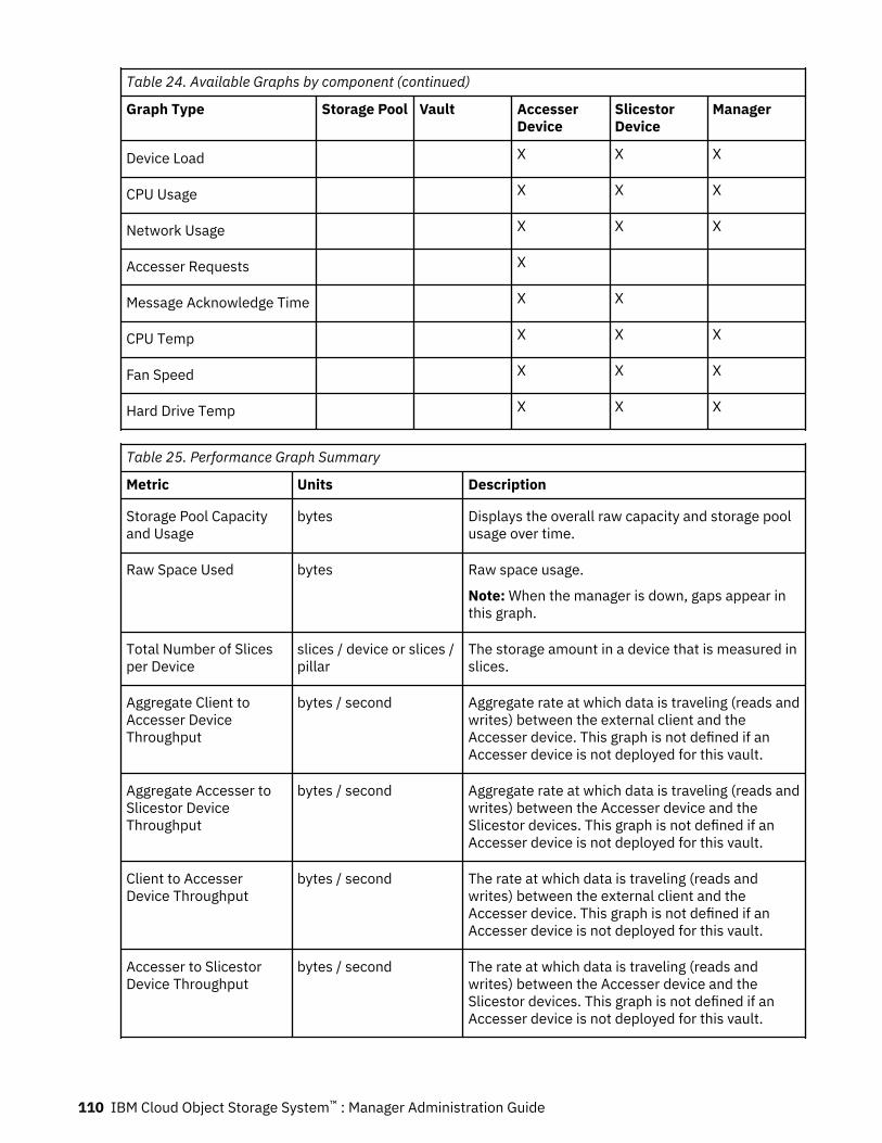
Table 24. Available Graphs by component (continued)
Graph Type Storage Pool Vault AccesserDevice
SlicestorDevice
Manager
Device Load X X X
CPU Usage X X X
Network Usage X X X
Accesser Requests X
Message Acknowledge Time X X
CPU Temp X X X
Fan Speed X X X
Hard Drive Temp X X X
Table 25. Performance Graph Summary
Metric Units Description
Storage Pool Capacityand Usage
bytes Displays the overall raw capacity and storage poolusage over time.
Raw Space Used bytes Raw space usage.
Note: When the manager is down, gaps appear inthis graph.
Total Number of Slicesper Device
slices / device or slices /pillar
The storage amount in a device that is measured inslices.
Aggregate Client toAccesser DeviceThroughput
bytes / second Aggregate rate at which data is traveling (reads andwrites) between the external client and theAccesser device. This graph is not defined if anAccesser device is not deployed for this vault.
Aggregate Accesser toSlicestor DeviceThroughput
bytes / second Aggregate rate at which data is traveling (reads andwrites) between the Accesser device and theSlicestor devices. This graph is not defined if anAccesser device is not deployed for this vault.
Client to AccesserDevice Throughput
bytes / second The rate at which data is traveling (reads andwrites) between the external client and theAccesser device. This graph is not defined if anAccesser device is not deployed for this vault.
Accesser to SlicestorDevice Throughput
bytes / second The rate at which data is traveling (reads andwrites) between the Accesser device and theSlicestor devices. This graph is not defined if anAccesser device is not deployed for this vault.
110 IBM Cloud Object Storage System™ : Manager Administration Guide
Table 25. Performance Graph Summary (continued)
Metric Units Description
Scanning Rate sources / second The rate at which the scanning agent of one ormore devices are scanning the storage for missingwrites/deletes.
Estimated High PriorityData Sources to Rebuild
sources The Estimated High Priority Data Sources toRebuild graph represents the current amount ofprioritized rebuild work per set on the system.Prioritized rebuild work is rebuild work for sourcesthe system has identified as important. The trendof this graph relates to overall system health. Adownward trend means rebuild work isprogressing, and important rebuild work is beingcompleted. An upward trend indicates the systemis finding important prioritized rebuild work andthat work is outpacing the rate at which work isbeing completed. A flat line represents incomingwork is keeping pace with how fast prioritizedrebuild work is being completed.
Rebuild Slices Sent slices / second The rate at which the rebuilding agent of one ormore Slicestor nodes have reconstructed missingwrites and have sent to a destination Slicestornode. Measured in slices/sec.
Rebuild Deletes Sent slices / second The rate at which the rebuilding agent of one ormore Slicestor nodes have discovered missingdeletes and have sent to a destination Slicestornode.
Rebuild Bytes Sent bytes / second The rate at which the rebuilding agent of one ormore Slicestor nodes have reconstructed missingwrites and have sent to a destination Slicestornode.
Rebuild Slices Received slices / second The rate at which missing writes have beenrecovered.
Rebuild DeletesReceived
slices / second The rate at which missing deletes have beenrecovered.
Rebuild Bytes Received bytes / second The rate at which missing writes have beenrecovered.
Chapter 6. Monitoring the system 111
Table 25. Performance Graph Summary (continued)
Metric Units Description
Disk Usage bytes / second Provides a consolidated view of disk read/writespeeds for all drives in device.
Read Show
Display all read lines for all drives in the graph.
Read Hide
Hide all read lines for all drives in the graph.
Write Show
Display all write lines for all drives in the graph.
Write Hide
Hide all write lines for all drives in the graph.
Aggregate Read
Sum all toggled-on read lines and display asingle summed line.
Aggregate Write
Sum all toggled-on write lines and display asingle summed line.
The legend items can be sorted in three differentways:
• bay number (increasing)• read speed (decreasing)• write speed (decreasing).
Click the headers in the legend to trigger thesorting. The legend is sorted by bay number whenthe graph is initially loaded.
VM devices display block device name instead ofbay numbers and are sorted in lexographicallyincreasing order.
When aggregate lines are displayed instead ofindividual lines, the aggregate lines adjust asindividual lines are toggled by using the color boxin the legend.
For export, only toggled-on lines are included inthe .csv output file.
112 IBM Cloud Object Storage System™ : Manager Administration Guide
Table 25. Performance Graph Summary (continued)
Metric Units Description
Device Load Processes Average number of processes that are either in arunnable or uninterruptible state. A process in arunnable state is either using the CPU or waiting touse the CPU. A process in uninterruptible state iswaiting for some I/O access, for example, waitingfor disk. Load averages are not normalized for thenumber of CPUs in a system, so a load average ofone means that a single CPU system is loaded allthe time while on a 4 CPU system it means it wasidle 75% of the time. For a lightly loaded device,the vertical axis might show m for milli-percent.
CPU Usage % A measure of how much time the CPUs spend onuser applications and O/S (Operating System)functions. Even when the CPU usage is 0% theCPUs are still performing basic system tasks. Thegraph shows cumulative CPU utilization by thedevice. Dual and quad core CPUs might report two,four, or even eight CPUs, depending on the specificdevice. Therefore, loads of greater than 100% aretypical. CPU Wait, also shown, represents thepercentage of time that the CPU is waiting on I/O,which includes disk, network, and memory delays.If your device's CPU uses hyperthreading of CPUs,it could take the percentage to greater than thetotal number of CPUs x 100%.
Network Usage bytes / second Inbound and outbound network traffic.
Accesser Requests requests / second HTTP requests to the Accesser device.
Message AcknowledgeTime
ms Measured from the time an Accesser device isready to send a data packet until the Slicestordevice has written to the operating system andresponded back. Long message acknowledgetimes can indicate slow Slicestor devices. If anAccesser device does not have a connection toSlicestor devices, no data is displayed in the graphduring this period.
CPU Temperature A critical alarm is sent to the Monitor EventConsole if the CPU (Central Processing Unit, that is,the server microprocessor) temperature exceeds90°C. Check the ambient temperature of thedevice immediately.
Chapter 6. Monitoring the system 113
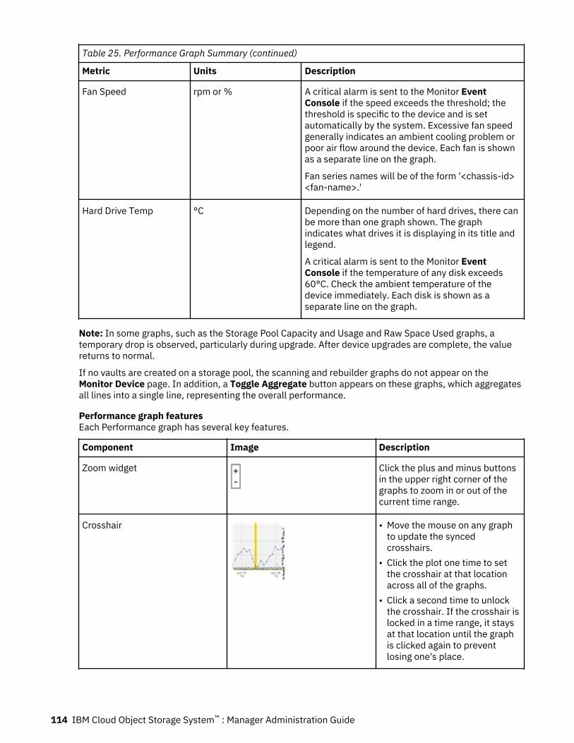
Table 25. Performance Graph Summary (continued)
Metric Units Description
Fan Speed rpm or % A critical alarm is sent to the Monitor EventConsole if the speed exceeds the threshold; thethreshold is specific to the device and is setautomatically by the system. Excessive fan speedgenerally indicates an ambient cooling problem orpoor air flow around the device. Each fan is shownas a separate line on the graph.
Fan series names will be of the form '<chassis-id><fan-name>.'
Hard Drive Temp °C Depending on the number of hard drives, there canbe more than one graph shown. The graphindicates what drives it is displaying in its title andlegend.
A critical alarm is sent to the Monitor EventConsole if the temperature of any disk exceeds60°C. Check the ambient temperature of thedevice immediately. Each disk is shown as aseparate line on the graph.
Note: In some graphs, such as the Storage Pool Capacity and Usage and Raw Space Used graphs, atemporary drop is observed, particularly during upgrade. After device upgrades are complete, the valuereturns to normal.
If no vaults are created on a storage pool, the scanning and rebuilder graphs do not appear on theMonitor Device page. In addition, a Toggle Aggregate button appears on these graphs, which aggregatesall lines into a single line, representing the overall performance.
Performance graph featuresEach Performance graph has several key features.
Component Image Description
Zoom widget Click the plus and minus buttonsin the upper right corner of thegraphs to zoom in or out of thecurrent time range.
Crosshair • Move the mouse on any graphto update the syncedcrosshairs.
• Click the plot one time to setthe crosshair at that locationacross all of the graphs.
• Click a second time to unlockthe crosshair. If the crosshair islocked in a time range, it staysat that location until the graphis clicked again to preventlosing one's place.
114 IBM Cloud Object Storage System™ : Manager Administration Guide
Component Image Description
Expand Graph Button Click the icon that is displayedbelow to enlarge a graph to fullscreen.
Plot selection Click and drag over a time rangein the graph to zoom into thattime range. A light orangehighlight is added until themouse is released, indicatingwhat the new range is. Plotselection range is limited togreater than 5 minutes.
Share functions Click the Share link to share agraph. A link is generated thatcan be distributed. When the linkis visited the time range visibleupon creation of the link isdisplayed.
Export link The current time range that isviewed on the graph can beexported as a .csv file anddisplays two columns for eachdata series. One contains thedate. The other contains thevalue.
Pan functions The graph pans left or rightapproximately 3/4 of the currentview to allow for graph traversalin the same time range.
Graph controls
Storage Pool page (scanning, outgoing and incoming rebuild, data reallocation graphs)A graph control mechanism on the Storage Pool page can be used with Scanning/Rebuilding charts.
Graph control is only visible when the Storage Pool is configured in the following ways:
• For unmerged Storage Pools, there exist one or more Vaults with IDA width that is less than the StoragePool width.
• For any merged Storage Pools regardless of number of unique IDA widths of deployed Vaults.
Graph control allows the Scanning/Rebuilding statistics to be grouped and rolled-up by logical entities,such as Storage Pool Sets and Stripes, for monitoring its activity at different levels of granularity.
The least granular view is the Scanning/Rebuilding statistics rolled up to the Storage Pool level. In thisview, all Scanning/Rebuilding activity is summed across all devices that are associated with the StoragePool for a comprehensive view of Scanning/Rebuilding performance.
There is a middle view called Stripes. Stripes are grouping of devices within a Storage Pool. Depending onthe unique IDA width of deployed vaults in the Storage Pool, there can be one or more numbers of
Chapter 6. Monitoring the system 115
Stripes. Stripes are categorized by unique IDA width of deployed Vaults in a Storage Pool. There is aselection that lists out all the unique IDA widths. When a width is clicked, it refreshes all the openScanning/Rebuilding graphs to show statistics for all Stripes that exist in the define IDA width.
The most granular view is seeing statistics for individual devices. They can be viewed after a Storage PoolSet is selected (if there is more than one), a unique IDA width (if there is more than one), and a Stripe.
The graph control has the following selections:
• Selection by Storage Pool Set• Selection by Unique IDA Width• Selection by Stripe
Monitor Accesser page: message acknowledge time (MAT) graphsThe MAT graph is enabled with a statistical analysis tool for more efficient troubleshooting and diagnosis.
This tool is available when an Accesser appliance is deployed to multiple Storage Pools, expanded/merged Storage Pools, or to multiple vaults with differing unique widths. Three statistics are available -max, 95th percentile, and average. When selected, it applies the statistical analysis on the devices that isconsistent with the entity that is selected. For example, if you select average and a Storage Pool, itaverages all the data points of all the devices that belong in that Storage Pool. This analysis is intended tobe used to find outliers and anomalies by looking at a summarized view and be able to drill down to findproblematic sources. The statistic analysis is disabled when looking at data on a per-device basis.
Monitor Accesser page: Accesser request graphsThe Accesser request graph displays incoming HTTP requests to the Accesser device.
Above the graph are controls to switch the graph mode and to filter the graph. The graph has two modes:request and response. In request mode, graph lines are displayed for each request type, and the filtercontrol allows the selection of a particular response code. In response mode, graph lines are displayedfor each response code, and the filter control allows the selection of a particular request type.
Any unsupported HTTP request types are grouped under a single label: INVALID.
Annotated graphsA small Event Console annotated graph that contains annotation data points appears under each eventand audit data graph.
Note: This graph shows data consistent with the currently displayed Event Console entries. It is possibleto pan the annotated graph to time periods before and after this time frame, but the data will not berefreshed. To show more data, first click the Show More link below the list in the Event Console. Thegraph updates automatically when the Event Console data refreshes.
Annotation data points are color-coded based on the severity/type of each event. When annotations areclicked, the corresponding entry is clicked/highlighted in the Event Console so it can be scrolled into viewto correlate events with graph inconsistencies.
Annotated graphs have the same interactive functions as the regular performance graphs (Crosshair, plotselection, data point labels on-hover).
The Event Console and the annotated graphs have the same exact content so they are always in sync.Every time the Event Console is updated, the annotated graphs reflect the new values. If no EventConsole data exists, the annotated graphs are hidden.
Disabling events on a device
About this task
Note: To disable events on a device, Event Suppression must first be enabled per “Suppressing deviceevents” on page 73.
116 IBM Cloud Object Storage System™ : Manager Administration Guide
Disabling events on a device can be useful when, for example, a bad/misbehaving device is generatingnumerous events and email alerts.
To enable/disable the ability to suppress events on a device:
Procedure
1. When on the Monitor page, under the Device Summary section, click the device where you want todisable events.
2. Click Disable Events in the upper right corner of the page.
Note: If Disable Events is not present, then you need to enable Event Suppression per “Suppressingdevice events” on page 73.
3. Select one of the three options.
• Hours• End-date• Indefinite
4. Pick the wanted option and complete secondary fields (if any) that become enabled.5. Click Update.
Device summary
Filtering devices by using tabsOn the Monitor and Configure Device Summary pages, three tabs at the top of the page provide quickfilters to limit the list of devices displayed.
• The left tab is for All Devices, which include both Slicestor devices and Accesser devices (Managerdevices are not included on the device summary pages).
• The center tab is for Slicestor Devices.• The right tab is for Accesser Devices.
Click one of these three tabs to filter the list of devices to include only the ones that are specified on thetab.
Default tab filters
If the user clicks Devices in the left navigation panel, the All Devices tab is selected and no filters areapplied.
If the user clicks the Slicestor devices or Accesser devices in the left navigation panel, the page isrendered with the respective device tab already selected and the devices pre-filtered.
In the quick filters for Slicestor devices and Accesser devices, a pie chart and health bars are alsoavailable. Click the segments of the pie chart or the health bar in a tab to filter the list of results. Theindividual slices of the pie chart change color when the user hovers over them. The individual health barsare highlighted with a colored border when the user hovers over them.
Filtering devices by using extra filtersThe Monitor and Configure Device Summary pages also have a gray box with a collection of filters tolimit the list of devices.
• Health by using check boxes• Sites, Cabinets, Models, Storage Pools, Storage Pool Sets and Access Pools by using drop-down menus
Select one or more of any of the options in the drop-down menus or check boxes to filter the list ofdevices.
Chapter 6. Monitoring the system 117
The user can enter extra free text to further limit the results in the Search Results field below the graybox. The Search Results field accepts one or more terms that are separated with a space. It does notsupport AND, OR, or None logical operators or keywords.
Apply filters to device list resultsAll filters are combined when filtering the list ((logical)AND). Within each filter, if more than one option isselected, any of those selected options can be included when filtering the list ((logical)OR).
To limit the devices that are displayed to the ones with the following attributes:
• Warning or Unhealthy states• Storage Pools ABC or DEF• The terms Seattle and S3 in their names
Perform the following steps:
1. Select Warning and Unhealthy in the Health check boxes.2. Select ABC and DEF in the Storage Pool drop-down menu.3. Type Seattle S3 in the Search Results field.
The requested filtered result is displayed.
118 IBM Cloud Object Storage System™ : Manager Administration Guide
Chapter 7. Maintenance
OverviewThis information covers maintenance activities, such as upgrade, tools to support troubleshooting(particularly log collection), and reports. All reports can be exported to a .csv file, sent via email ondemand, or sent automatically based on a configured schedule.
Note: Any custom configuration modifications that are made to the Accesser device that were not madeby using the Manager Web Interface will need be redone after you upgrade.
UpgradeUpgrading is performed from the Maintenance tab. The upgrade process supports n-2 upgrades, whichmeans the starting point of a direct upgrade is a release version whose second digit differs by less than orequal to two. Contact IBM Customer Support for further information.
Upgrading is based on the concept of a single upgrade queue, containing the devices to be upgraded. Adevice selected for upgrade is placed in a queue and upgraded, while ensuring the health of the vaultsacross the system are not compromised. Before a device upgrade, the Manager application tests to seewhether the health of any of the vaults that are associated with the device are negatively impacted if thedevice goes down. Upgrade can be performed on a single device, a handful of devices, or an entireaccess/storage pool. Checks will be performed to ensure that a device comes back online correctly afterupgrade.
Note: When upgrading to a new version of ClevOS, some incidents are automatically closed and reopenedif they still exist after upgrade.
Note: Protection cannot be enabled on a vault or container until all devices that will host the protectedvault or container have been upgraded to ClevOS 3.14.1 or newer.
In a typical device upgrade, the state transitions as follows:
Table 26. Typical device upgrade state transitions
State transitions Detail
Requiring The device software version differs from theManager device.
Enqueuing The command to upgrade this device is sent, but astatus update has not been performed. Statusupdates occur every 10 seconds.
Precheck The device is performing a pre-upgradeconsistency check to ensure that the system iscapable of being upgraded.
Precheck Failed When a precheck fails, this status appears andremains until the device is upgraded again.Reloading the page removes this status.
Pending The device is added to the upgrade queue.
Initiated The device has begun the upgrade process.
© Copyright IBM Corp. 2017, 2020 119
Table 26. Typical device upgrade state transitions (continued)
State transitions Detail
Downloading The upgrade package is copied to the device.
Stopping The command to stop the device process has beenissued.
Capturing Integrity The device is capturing integrity state that will beused after upgrading the device to ensure theupgrade completed successfully.
Rebooting The device is being rebooted with a new softwareversion.
Verifying Integrity The device is verifying that it upgradedsuccessfully.
Success All data integrity checks passed and the correctversion of the software is confirmed.
Failure The device did not pass the data integrity checksand the correct version of the software is notconfirmed.
Current The device has the most recent software version.
Prechecks are performed before adding devices into the upgrade queue. During an upgrade, severalscenarios can occasionally occur that require operator intervention. As part of an upgrade, various optionsare presented to the user if unexpected conditions arise during a device upgrade. In particular, thefollowing scenarios might arise:
• Prechecks can fail.• Device upgrade takes longer than expected.• Device processes take longer than expected to stop.• General issues arise during a device upgrade.
If problematic devices exist within a pool, a message appears. An exclamation point (icon) appears on theleft side of the page. It indicates that user intervention is needed on that pool.
If the device does not upgrade successfully, an icon appears with an alert message on the same page;manual intervention is needed. The device can be removed from the upgrade queue and the upgraderetried. Remove applies to a single device in the Pending or Failure state. A Remove button exists to theright of the device (right portion of the upgrade page), which when selected removes the device from theupgrade queue. After a device is removed, the status will be Requiring. Upgrade is attempted only if vaulthealth will not be compromised. Problems encountered when software updates fail are identified throughmessages.
Upgrade detects circumstances in which device processes cannot be stopped in a timely manner. Whendetected, an icon appears, and a Force Kill button is displayed. If selected, upgrade forces termination ofthe process.
Upgrade also detects scenarios where restart, download, or integrity verification take longer thanexpected. If this occurs, the device can be removed from the upgrade queue by using the Force Removalbutton. Integrity failures result in an incident appearing in the Open Incidents view.
Note:
120 IBM Cloud Object Storage System™ : Manager Administration Guide
If IE is being used to upgrade, set the following option:
1. Go to Internet Options. It is available from Tools (IE8) or a circular settings icon (IE9).2. In the General tab, select Settings | Browsing history.3. In the pop-up window for the Check for newer versions of stored pages section, select the Every
time I visit the webpage option.
The high-level procedure consists of the following steps:
1. Transfer the upgrade compressed file to the machine running the browser. (See alternative procedurein the note below.)
2. Browse and upload one upgrade compressed file from the Upgrade page. (See alternative procedurein the note below.)
3. Initiate the Manager upgrade from the Upgrade page.
Note: Perform a backup of the Manager database before continuing. At the end of the upgrade, logback in to the Manager.
4. Initiate the upgrade of the remaining devices from the Upgrade page.
In some circumstances, a desirable alternative to Steps 1 and 2 is to transfer the image file directly to theManager device from an alternative source machine. It is beneficial when the operator is working over alow-bandwidth connection (for example, wifi or trans-continental) for which the upload time of theupgrade image is prohibitive. In such cases, the operator can log in to a jump host elsewhere on thenetwork that already contains the upgrade image and send it directly to the Manager device. Thefollowing curl command accomplishes this:
$ curl --insecure -u <ADMIN_USERNAME> -F upgradeFile=@<UPGRADE_IMAGE> -F action=installUpgradeFile https://<MANAGER_IP>/manager/upgrade.adm
Table 27. Description of Options
Option Description
—insecure Manager device certificate does not need to verifyas the Upgrade file is not secret information.
-u <ADMIN_USERNAME> Administrative user name
-F upgradeFile=@<UPGRADE_IMAGE> Upgrade image to send to the manager.
-F action=installUpgradeFile Manager device extracts the provided file to disk.
(https://<MANAGER_IP>/manager/upgrade.adm)
URL of the upgrade page.
When run, the command prompts for the password that is associated with the specified user.
To determine the current version of the system, go to the Maintenance tab in the Manager Web Interface.
Before clicking Upgrade, the upgrade compressed file that is provided with the release needs to becopied to the machine running the browser.
Click Upgrade from the Maintenance tab to show the Upgrade System Software page.
The Upgrade System Software page shows three steps:
1. Upload One Manager Upgrade File
Browse for the upgrade file and click Upload.
Chapter 7. Maintenance 121
Note: Only one upgrade file can be uploaded to the Manager at a time. If another file is uploadedduring an upgrade, an error message appears until the page is reloaded.
Note: The behavior of the upload progress is different based on the browser:
• Firefox and Internet Explorer display an upload progress bar in the Manager Web Interface.• Chrome and Safari do not show a progress bar. The browser window displays progress.
2. Upgrade Manager
Click Start Upgrade.
Attention: Do not restart the Manager while upgrade is in progress. Manager upgrade takesapproximately 15 minutes. If the upgrade takes longer, contact IBM Customer Support.
After the Manager upgrade completes, a dialog box appears. Click Log back into the manager toreturn to the log in page.
Note: When you upgrade the Manager to ClevOS 3.10.1 or later, it might not be possible to log inimmediately since an extra 20 - 30 minutes might be needed for the Manager application to becomeavailable. On systems with large databases, the time might be longer. Contact Customer Support if ittakes longer than 30 minutes to successfully log in to the Manager.
3. Upgrade Devices
Accesser devices are grouped by Access Pool. Slicestor devices are grouped by Storage Pool, anddevices that are not associated with any particular pool are placed in their own group "Devices not in astorage pool or access pool." At the left of the page, for a storage pool in which all devices are to beupgraded, the following options are available: "Upgrade Entire Storage Pool," "Upgrade Entire Set," or"Upgrade" a single device. Similarly, for an access pool, the following options are available: "UpgradeEntire Access Pool" or "Upgrade" a single device. For "Devices not in a storage pool or access pool,"the following options are available: "Upgrade All Devices Not in a Pool" or "Upgrade" a single device.Upgrade is possible when the status is Requiring, Pre-check Failed, or Failure.
Note: Vault access (unavailable) events will be generated after an Accesser device upgrade completesif the core process is down, particularly in single Accesser device configurations.
The full upgrade procedure is as follows:
a. Browse and upload the upgrade file as part of Step 1 on the Upgrade page.
Note: Only one upgrade file can be uploaded to the Manager at a time. If another file is uploadedduring an upgrade, an error message appears until the page is reloaded.
b. If a backup is configured for this Manager, go to Step 8.c. Click Start Upgrade in Step 2 under the Upgrade Manager section.d. If the Upgrade has new End User License Agreements (EULA), then Accept License Agreement to
Continue is made available for the user under Step 3 - Upgrade Devices, which on click, displaysan IBM standard and non-IBM End User License Agreements (EULA) in a pop-up window similar tothe End User License Agreement figure shown. The user needs to complete the Print Name(License Acceptor) field and check the appropriate box and click Accept IBM & non-IBM Licensesto accept the EULA, otherwise, device upgrades are not allowed.
e. If no backup configuration is created for this Manager, you are prompted to configure the backup,or upgrade without performing a backup.
Attention: IBM strongly recommends that the Manager is backed up before upgrade toensure preservation of Manager data.
Click Configure backup.f. On the Backup Configuration screen, specify encryption and FTP values as prompted and clickConfigure in the Backup Configuration action bar.
122 IBM Cloud Object Storage System™ : Manager Administration Guide

It is also possible to perform a manual backup from the Administration tab, but when you returnto the upgrade step you are prompted again to configure the backup or upgrade withoutperforming a backup. Then, you can select to upgrade without performing backup.
g. Refer to managerAdmin_administration_set_backup_configuration_parameters.dita for how toconfigure the backup parameters. On completion of the Backup Configuration, return to theUpgrade page by clicking the Maintenance tab and then clicking Upgrade.
h. Click Start Upgrade in Step 2 of the Upgrade page (Upgrade Manager).i. A prompt offers the option to back up the Manager or cancel the operation. Click Backup Manager
Now.j. On completion of the backup, you are prompted to proceed with the upgrade or cancel the
operation. Click Proceed with Upgrade.k. The Manager will now be upgraded. Status updates are presented in the dialog box.
Once the upgrade is verified, the button allowing you to log back in to the Manager Web Interfaceis enabled. Click Log back into the Manager Web Interface.
Note: When you upgrade the Manager to ClevOS 3.10.1 or later, it might not be possible to log inimmediately since an extra 20 - 30 minutes might be needed for the Manager application tobecome available. On systems with large databases, the time might be longer. Contact CustomerSupport if it takes longer than 30 minutes to successfully log in to the Manager.
l. The Manager home page displays a banner at the top of the page that indicates there are devicesin the system running a different version of software and provides a link.
Click this link to proceed to the Upgrade page.m. The Manager upgrade portion of the UI shows the upgraded version of the Manager and report
that no upgrade is available.n. Upgrade Devices in Step 3.
Table 28. Supported Operations for Upgrade
Operation Action
Remove This applies only to a single device in thePending or Failure state. Click the "Remove"button to the right of the device (right portionof the upgrade page) to remove the device fromthe upgrade queue.
Remove Entire Set The "Remove Entire Set" button is enabled ifthere are 1 or more devices in the storage poolset that are in the Pending or Failure state.
Remove Entire Storage Pool The "Remove Entire Storage Pool" button isenabled if there are 1 or more devices in thestorage pool that are in the Pending or Failurestate.
See the section on “Upgrade settings configuration” on page 124 for supported operations whenchanging the upgrade settings.
4. Change in Manager Properties Upon Upgrade
During upgrades, the default value for "Object Access" is decided based on the following rules:
a. If the dsNet has no vaults, read and listing option are selected.b. If the dsNet has only standard vaults, read and listing option are selected.c. If the dsNet has only container vaults
Chapter 7. Maintenance 123
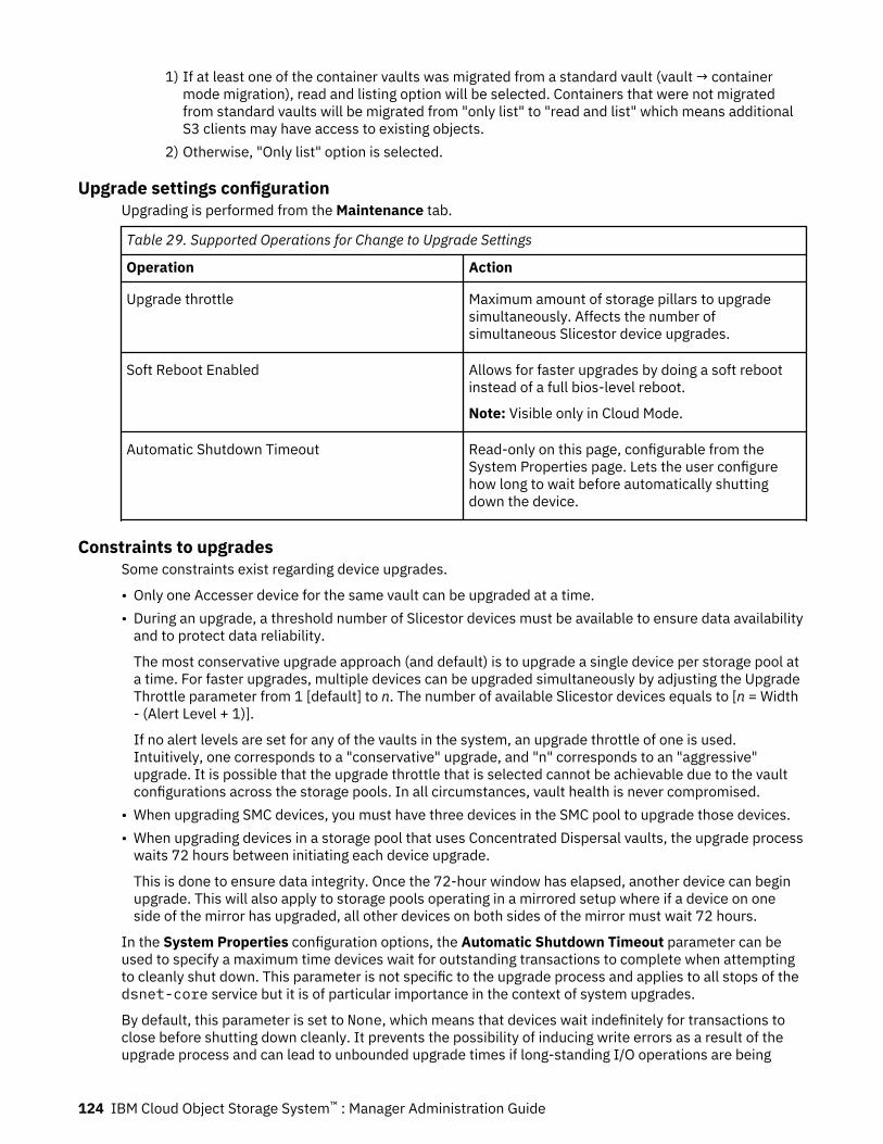
1) If at least one of the container vaults was migrated from a standard vault (vault → containermode migration), read and listing option will be selected. Containers that were not migratedfrom standard vaults will be migrated from "only list" to "read and list" which means additionalS3 clients may have access to existing objects.
2) Otherwise, "Only list" option is selected.
Upgrade settings configurationUpgrading is performed from the Maintenance tab.
Table 29. Supported Operations for Change to Upgrade Settings
Operation Action
Upgrade throttle Maximum amount of storage pillars to upgradesimultaneously. Affects the number ofsimultaneous Slicestor device upgrades.
Soft Reboot Enabled Allows for faster upgrades by doing a soft rebootinstead of a full bios-level reboot.
Note: Visible only in Cloud Mode.
Automatic Shutdown Timeout Read-only on this page, configurable from theSystem Properties page. Lets the user configurehow long to wait before automatically shuttingdown the device.
Constraints to upgradesSome constraints exist regarding device upgrades.
• Only one Accesser device for the same vault can be upgraded at a time.• During an upgrade, a threshold number of Slicestor devices must be available to ensure data availability
and to protect data reliability.
The most conservative upgrade approach (and default) is to upgrade a single device per storage pool ata time. For faster upgrades, multiple devices can be upgraded simultaneously by adjusting the UpgradeThrottle parameter from 1 [default] to n. The number of available Slicestor devices equals to [n = Width- (Alert Level + 1)].
If no alert levels are set for any of the vaults in the system, an upgrade throttle of one is used.Intuitively, one corresponds to a "conservative" upgrade, and "n" corresponds to an "aggressive"upgrade. It is possible that the upgrade throttle that is selected cannot be achievable due to the vaultconfigurations across the storage pools. In all circumstances, vault health is never compromised.
• When upgrading SMC devices, you must have three devices in the SMC pool to upgrade those devices.• When upgrading devices in a storage pool that uses Concentrated Dispersal vaults, the upgrade process
waits 72 hours between initiating each device upgrade.
This is done to ensure data integrity. Once the 72-hour window has elapsed, another device can beginupgrade. This will also apply to storage pools operating in a mirrored setup where if a device on oneside of the mirror has upgraded, all other devices on both sides of the mirror must wait 72 hours.
In the System Properties configuration options, the Automatic Shutdown Timeout parameter can beused to specify a maximum time devices wait for outstanding transactions to complete when attemptingto cleanly shut down. This parameter is not specific to the upgrade process and applies to all stops of thedsnet-core service but it is of particular importance in the context of system upgrades.
By default, this parameter is set to None, which means that devices wait indefinitely for transactions toclose before shutting down cleanly. It prevents the possibility of inducing write errors as a result of theupgrade process and can lead to unbounded upgrade times if long-standing I/O operations are being
124 IBM Cloud Object Storage System™ : Manager Administration Guide

performed on the system. The Automatic Shutdown Timeout can be used to place an upper bound onthe amount of time the dsnet-core process waits for the transaction to close before forcefully endsoutstanding transactions and completing the shutdown process.
The following options are available:
• None• 15 min• 30 min• 1 hour• 2 hours• 4 hours• 8 hours• 16 hours
Selecting a value other than None prompts a warning message that indicates active writes are droppedand in-flight data that is not yet committed to the system might be lost.
When a device begins the graceful shutdown of the dsnet-core process in preparation for upgrade, itwaits up to the selected timeout for the shutdown to complete. If shutdown completes before thetimeout, the device upgrade proceeds normally. If not, after timeout expiration, automatic terminationwill be performed on the dsnet-core process, and any active writes will be canceled.
On the right side of the Manager Web Interface under the upgrade queue, for the device being upgraded,a countdown indicates the amount of time that is left before automatic termination. This operation can bechanged or stopped by setting the Automatic Shutdown Timeout to a different value or None. If a newvalue is specified (something other than None), any previous time that is spent in the stopping state isaccounted for.
Migrating devices to IPv6Migrate your devices to IPv6 to guard against the eventual depletion of IPv4 addresses and ensure thatno outage in continuous connectivity occurs.
About this taskTo use IPv6 in the system, all devices must be upgraded to ClevOS 3.10.1 or later. Devices that arebrought in to an IPv6-enabled system that are not capable of IPv6 can function only if Slicestor® Deviceswithin the same Vault do not have IPv6 addresses configured. These devices must be set to the sameversion as the system and might not provide all functions until this requirement is fulfilled.
Note: Native File Interface and geo-dispersed efficiency upgrades do not yet support IPv6.
When all devices are upgraded to an IPv6-enabled load, the system can run several networkimplementations:
• Single-stack IPv4 (The Manager appliance and all devices are configured with IPv4 addresses only).• Dual-stack IPv4/IPv6 (The Manager appliance and all devices are configured with both IPv4 and IPv6
addresses).
Tip: You can set IPv6 as the preferred IP protocol for object operations within the system on theConfigure > Configure System Properties page. For more information, see “Configuring systemproperties” on page 85.
• Single-stack IPv6 (The Manager appliance and all devices are configured with IPv6 addresses). IPv4addresses are removed from the Manager and all devices.
• Mixed IPv4/IPv6 (The Manager appliance is configured with both IPv4 and IPv6 addresses). Somestorage pools have devices that are configured with IPv6 addresses, while other storage pools havedevices that are configured with IPv4 addresses only.
Use the following procedure to upgrade your system to a single-stack IPv6 implementation.
Chapter 7. Maintenance 125
Procedure
1. Upgrade the Manager device to ClevOs 3.10.1 or later.For more information about upgrading the Manager, see “Upgrade” on page 119.
2. Log in to the Manager device and update the IP address, network mask, and network gateway to useIPv6 addresses.For more information on the nut commands, see the "Channel utility" section of the ApplianceConfiguration Guide.
3. Upgrade each device to ClevOs 3.10.1 or later.
Note: The system does not use IPv6 addresses until all devices are upgraded.4. Log in to each device and update the IP address, network mask, network gateway, and Manager IP to
use IPv6 addresses.For more information on the nut commands, see the "Channel utility" and "Manager utility" sections ofthe Appliance Configuration Guide.
Note: Ensure that you fully upgraded and updated each device before you move on to the next step.5. Log in to each device and remove any IPv4 addresses by specifying the IPv4 IP, network mask, and
network gateway addresses with no value.
IBM Cloud Object Storage Insight™
From the Maintenance tab, a user can read current IBM Cloud Object Storage Insight™ information anddetermine how the Manager device executes sessions with the IBM Cloud Object Storage Insight™ server.It is also possible to manually connect to the IBM Cloud Object Storage Insight™ server to send systemdata.
Leaving this feature enabled assists IBM support staff in resolving cases in a timely fashion. It can alsohelp find potential issues with drives, configuration, or software.
Currently, only a small amount of information is sent to IBM support. It includes some disk-relatedmetrics, metadata files, and the output of the following REST API calls:
• View System• Disk Drive and Device Report• Firmware Report• Version History Report
Authentication details are redacted and are not sent to or visible to IBM employees:
• Passwords (accounts, backup, LDAP, and so on)• Vault secret access keys• Account secret access keys• Private keys that are used for certificate generation.
When the anonymization settings are enabled, the best level of effort is made to redact or anonymizedpotentially sensitive data. Most configuration elements that indicate whether certain features are enabledor disabled are never redacted. For other types of information, the following tables illustrate how it'sprocessed before it is sent to IBM.
Table 30. Content never anonymized or redacted in IBM Cloud Object Storage Insight™
Entity Fields
Devices Advanced configuration, software, and firmware versions for devicesand drives, hardware information (model, serial number, and so on)for devices and drives, health-related information for devices anddrives
126 IBM Cloud Object Storage System™ : Manager Administration Guide
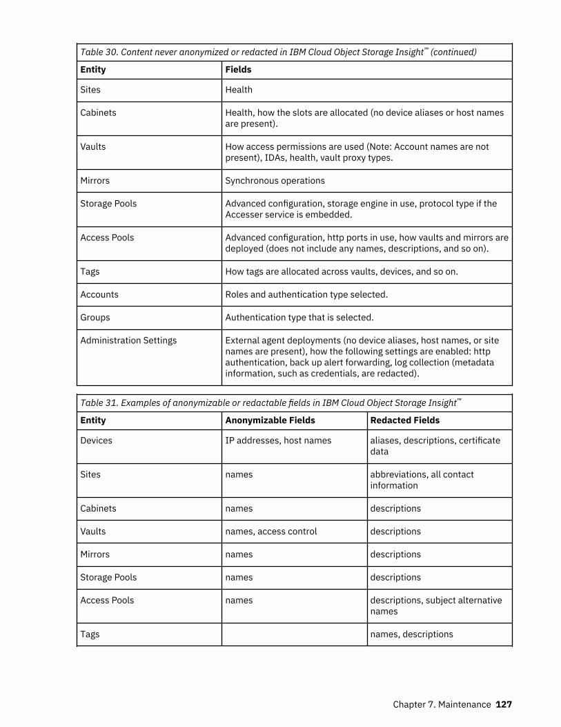
Table 30. Content never anonymized or redacted in IBM Cloud Object Storage Insight™ (continued)
Entity Fields
Sites Health
Cabinets Health, how the slots are allocated (no device aliases or host namesare present).
Vaults How access permissions are used (Note: Account names are notpresent), IDAs, health, vault proxy types.
Mirrors Synchronous operations
Storage Pools Advanced configuration, storage engine in use, protocol type if theAccesser service is embedded.
Access Pools Advanced configuration, http ports in use, how vaults and mirrors aredeployed (does not include any names, descriptions, and so on).
Tags How tags are allocated across vaults, devices, and so on.
Accounts Roles and authentication type selected.
Groups Authentication type that is selected.
Administration Settings External agent deployments (no device aliases, host names, or sitenames are present), how the following settings are enabled: httpauthentication, back up alert forwarding, log collection (metadatainformation, such as credentials, are redacted).
Table 31. Examples of anonymizable or redactable fields in IBM Cloud Object Storage Insight™
Entity Anonymizable Fields Redacted Fields
Devices IP addresses, host names aliases, descriptions, certificatedata
Sites names abbreviations, all contactinformation
Cabinets names descriptions
Vaults names, access control descriptions
Mirrors names descriptions
Storage Pools names descriptions
Access Pools names descriptions, subject alternativenames
Tags names, descriptions
Chapter 7. Maintenance 127

Table 31. Examples of anonymizable or redactable fields in IBM Cloud Object Storage Insight™
(continued)
Entity Anonymizable Fields Redacted Fields
Accounts usernames names, email addresses, anydata related to configuredauthentication mechanism
Groups names aliases, any data related toconfigured authenticationmechanism
Organizations names, domains descriptions, contact information
Administration Settings configured external certificateauthorities,
Name, login banner, email alertrules, SSH keys configuration,SMTP server information anduser name, back up serverinformation and user name, LDAPbind+search model configurationsettings, SMPV2 communitystring and allowed IP addresses,email addresses that receiveautomatic reports, AlertForwarding IP addresses/hostnames and communitystring, Keystone configurationsettings, External Agent names,and file names.
Configuring IBM Cloud Object Storage Insight™
About this task
Note: The hostname of the IBM Cloud Object Storage Insight server is ph1.cleversafe.com.
Procedure
1. Click Configure on the Cloud Object Storage Insight action bar.
The last successfully performed IBM Cloud Object Storage Insight™ session is displayed.
• View under the Automatic Settings bar.
– Enabled/Disabled status– Automatic schedule– Next automatic session time
• View under the Proxy Settings bar.
– Enabled/Disabled status– The configured proxy host name and port– Whether all requests that are routed through the proxy require basic HTTP authentication and the
configured credentials.• View under the Anonymization Settings bar.
– Whether data is anonymized before it is sent to IBM.
128 IBM Cloud Object Storage System™ : Manager Administration Guide
2. Click Configure on the IBM Cloud OBject Storage Insight Settings action bar to configure thesesettings.
3. Enable or disable automatic operation.Automatic operation is enabled by default. When automatic operation is enabled, the service runsperiodically in the background based on a schedule set by the IBM server.
Note: IBM determines the IBM Cloud Object Storage Insight™ automatic schedule. It cannot bemodified.
4. Enable or disable proxy settings.a) Enable or disable Use an HTTP Proxy. Enter the Proxy Hostname or endpoint and the Proxy Port.b) If authentication is also required, enable Use Authentication. Enter the Proxy Username and
associated Proxy Password.5. Enable or disable Data Anonymization.
When enabled, potentially sensitive information is anonymized or redacted before it is sent to IBMCustomer Support.
Manually starting IBM Cloud Object Storage Insight™ sessions
Procedure
1. Click Configure on the IBM Object Cloud Storage Insight action bar.2. Click Execute Session.
CAUTION: Execute Session cannot be pressed again for 1 hour after the session completes.
Viewing an anonymized object
Procedure
1. Click Configure on the IBM Cloud Object Storage Insight action bar.2. Click View on the View Anonymized IBM Cloud Object Storage Insight Data action bar.3. Enter the token that is provided by IBM support under the View Anonymized IBM Cloud Object
Storage Insight Data action bar.
Objects that match the token are displayed. Click a result to view to the appropriate Monitor page.
Note: The full token does not need to be entered. The Manager device returns a full list of objects thatmatch the partial token provided.
LogsFrom the Maintenance tab, you can collect internal logs across several different devices and send themto an SFTP or HTTP server, or choose not to send collected logs. Log collection can be performedmanually on demand or automatically based on a schedule. Log collection status can be viewed, whichdisplays "real-time" status.
Status that is presented on the Manager Web Interface includes the following items.
• Pending (default state until log collection starts).• Success (log collection completed successfully).• Error states (for example, device log collection failures, device communication issues, and so on).
If you choose not to send collected logs to an SFTP or HTTP server using the Manager Web Interface orManager REST API, but have Privacy Controls enabled, then dump-logs initiated from any device are stillredacted. For more information on Privacy Controls, see “Redacting client information” on page 132.
Note: Automatic log collection currently does not allow configuration of time and selection of devices. Ifthese capabilities are needed, manual log collection should be used.
Chapter 7. Maintenance 129
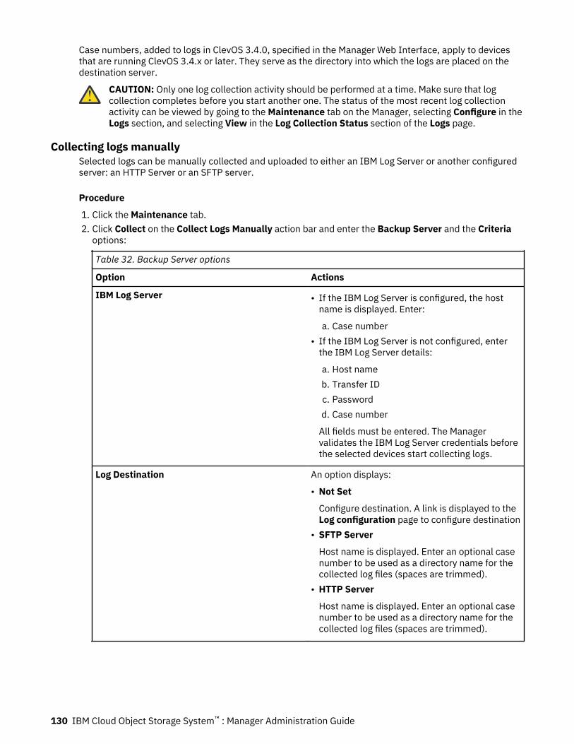
Case numbers, added to logs in ClevOS 3.4.0, specified in the Manager Web Interface, apply to devicesthat are running ClevOS 3.4.x or later. They serve as the directory into which the logs are placed on thedestination server.
CAUTION: Only one log collection activity should be performed at a time. Make sure that logcollection completes before you start another one. The status of the most recent log collectionactivity can be viewed by going to the Maintenance tab on the Manager, selecting Configure in theLogs section, and selecting View in the Log Collection Status section of the Logs page.
Collecting logs manuallySelected logs can be manually collected and uploaded to either an IBM Log Server or another configuredserver: an HTTP Server or an SFTP server.
Procedure
1. Click the Maintenance tab.2. Click Collect on the Collect Logs Manually action bar and enter the Backup Server and the Criteria
options:
Table 32. Backup Server options
Option Actions
IBM Log Server • If the IBM Log Server is configured, the hostname is displayed. Enter:
a. Case number• If the IBM Log Server is not configured, enter
the IBM Log Server details:
a. Host nameb. Transfer IDc. Passwordd. Case number
All fields must be entered. The Managervalidates the IBM Log Server credentials beforethe selected devices start collecting logs.
Log Destination An option displays:
• Not Set
Configure destination. A link is displayed to theLog configuration page to configure destination
• SFTP Server
Host name is displayed. Enter an optional casenumber to be used as a directory name for thecollected log files (spaces are trimmed).
• HTTP Server
Host name is displayed. Enter an optional casenumber to be used as a directory name for thecollected log files (spaces are trimmed).
130 IBM Cloud Object Storage System™ : Manager Administration Guide
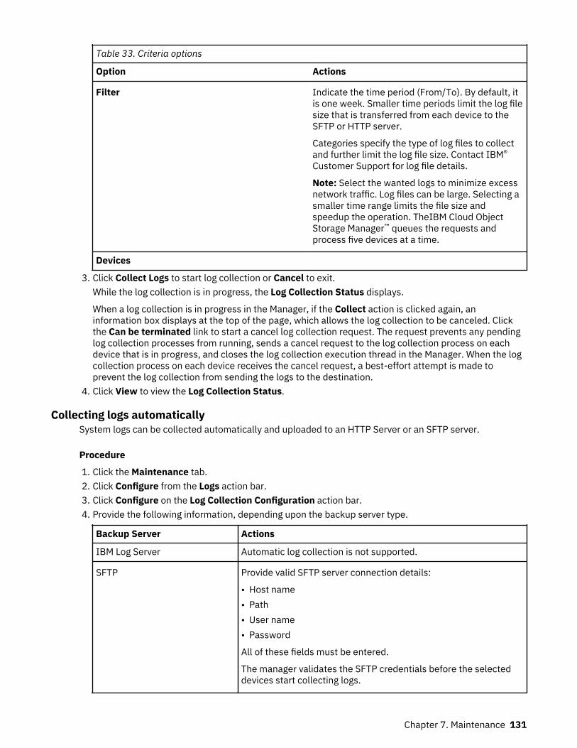
Table 33. Criteria options
Option Actions
Filter Indicate the time period (From/To). By default, itis one week. Smaller time periods limit the log filesize that is transferred from each device to theSFTP or HTTP server.
Categories specify the type of log files to collectand further limit the log file size. Contact IBM®
Customer Support for log file details.
Note: Select the wanted logs to minimize excessnetwork traffic. Log files can be large. Selecting asmaller time range limits the file size andspeedup the operation. TheIBM Cloud ObjectStorage Manager™ queues the requests andprocess five devices at a time.
Devices
3. Click Collect Logs to start log collection or Cancel to exit.While the log collection is in progress, the Log Collection Status displays.
When a log collection is in progress in the Manager, if the Collect action is clicked again, aninformation box displays at the top of the page, which allows the log collection to be canceled. Clickthe Can be terminated link to start a cancel log collection request. The request prevents any pendinglog collection processes from running, sends a cancel request to the log collection process on eachdevice that is in progress, and closes the log collection execution thread in the Manager. When the logcollection process on each device receives the cancel request, a best-effort attempt is made toprevent the log collection from sending the logs to the destination.
4. Click View to view the Log Collection Status.
Collecting logs automaticallySystem logs can be collected automatically and uploaded to an HTTP Server or an SFTP server.
Procedure
1. Click the Maintenance tab.2. Click Configure from the Logs action bar.3. Click Configure on the Log Collection Configuration action bar.4. Provide the following information, depending upon the backup server type.
Backup Server Actions
IBM Log Server Automatic log collection is not supported.
SFTP Provide valid SFTP server connection details:
• Host name• Path• User name• Password
All of these fields must be entered.
The manager validates the SFTP credentials before the selecteddevices start collecting logs.
Chapter 7. Maintenance 131
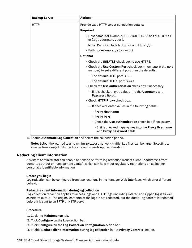
Backup Server Actions
HTTP Provide valid HTTP server connection details:
Required
• Host name (for example, 192.168.14.63 or fe00:d7::1or logs.company.com).
Note: Do not include http:// or https://.• Path (for example, /s3/vault)
Optional
• Check the SSL/TLS check box to use HTTPS.• Check the Use Custom Port check box (then type in the port
number) to set a different port than the defaults.
– The default HTTP port is 80.– The default HTTPS port is 443.
• Check the Use authentication check box if necessary.
– If it is checked, type values into the Username andPassword fields.
• Check HTTP Proxy check box.
– If checked, enter values in the following fields:
- Proxy Hostname- Proxy Port- Check the Use authentication check box if necessary.
• If it is checked, type values into the Proxy Usernameand Proxy Password fields.
5. Enable Automatic Log Collection and select the collection period.
Note: Select the wanted logs to minimize excess network traffic. Log files can be large. Selecting asmaller time range limits the file size and speeds up the operation.
Redacting client informationA system administrator can enable options to perform log redaction (redact client IP addresses fromdump-log output or management vaults), which can help meet regulatory restrictions on collectingpersonally identifiable information.
Before you beginLog redaction can be configured from two locations in the Manager Web Interface, which offer differentbehavior.
Redacting client information during log collectionLog collection redaction applies to access logs and HTTP logs (including rotated and zipped logs) as wellas netstat output. The original contents of the logs is not redacted, but the dump-log content is redactedbefore it is sent to an SFTP or HTTP server.
Procedure
1. Click the Maintenance tab.2. Click Configure on the Logs action bar.3. Click Configure on the Log Collection Configuration action bar.4. Enable Redact client information during log collection in the Privacy Controls section.
132 IBM Cloud Object Storage System™ : Manager Administration Guide
5. Click Update.
Redacting client information from management vaultsManagement vault redaction only applies to rotated and zipped access log files that were or are placed asobjects in a device's management vault. Existing objects are downloaded from the management vault,unzipped, redacted, zipped, and placed back in the management vault.
Procedure
1. Click the Configure tab.2. Click Configure in the Configure Mangement Vault action bar.3. In the Management Vault Options section, enable Backup HTTP access logs and Redact client
information. An "access log redaction time" must also be provided in the associated input field. Theunit of the input is days. Any non-negative integer is valid up to 36500 (days). Rotated HTTP accesslogs in management vaults will not be redacted until at least "access log redaction" days have passedafter the log was rotated. When Redact client information is enabled, a button to the RedactionStatus Report displays.
4. Click Update.
Collecting log statusStatus of last log collection. Only devices that were included in the last run appears.
About this taskCollection status updates periodically until no devices are in progress or pending. Devices are in a'Pending' state until a log collection is initiated; at that point, each device is in an 'In Progress' state until iteither succeeds or fails. A failed log collection is marked red with an error message dependent on thetype of failure. There is one 'Success' state, marked green.
Procedure
1. Click the Maintenance tab.2. Click Configure in the Logs action bar.3. Click View on the Log Collection Status taskbar to view the Log Collection Status page.4. Click Export in the Log Collection Status taskbar to export this data as a CSV file.
Note: Log collection status does not retain any historical information. Only the last known collection isretained.
Note: Failed states often contain troubleshooting information (text) regarding the cause of the failure.
Configuring device logsYou can set the Access Log Retention Period and Access Log Rotation Period.
About this task
Note: A system administrator can enable options to perform log redaction (redact client information frommanagement vaults or dump-log output), which may help with meeting regulatory restrictions oncollecting personally identifiable information. The Cloud Object Storage Manager has two locations wherelog redaction can be configured. The two locations configure different behavior. The first is on theConfigure Management Vault page under the Management Vault Options section (Redact clientinformation). For this case, Management Vault redaction applies to rotated and zipped access log filesthat exist or will be placed as objects in a device's management vault. After the access log’s "access logredaction time" passes, it will be downloaded from the management vault, unzipped, redacted, zipped,and placed back in the management vault. The second place where log redaction can be configured is theLog Collection Configuration page under the Privacy Controls section (Redact client information duringlog collection). In this case, Log Collection redaction applies to access logs and HTTP logs (including
Chapter 7. Maintenance 133
rotated and zipped logs) as well as netstat output. The original contents of the logs will not be redacted;the dump-log content will be redacted before it is sent to an SFTP or HTTP server.
Procedure
1. Click the Maintenance tab.2. Click Configure on the Logs action bar.3. Click Configure on the Device Log Configuration action bar.4. Select the desired Retention Period from the drop-down menu.
The Retention Period is the maximum amount of time that access logs are persisted on Accesserdevices and Slicestor devices.
5. Select the desired Rotation Period from the drop-down menu.The Rotation Period applies to both Vault Mode and Container Mode, controlling how often access logsare rotated. If "Not Set", the rotation only occurs once the access log reaches 500 MB. Otherwise, thelogs rotate based on the selected time interval. The Management vault upload of the access log occurswithin one (1) hour of the log rotation.
Note: An access log rotation period must be set if redaction of client information in the managementvault is enabled.
6. Click Update.
Note: The Retention Period and Rotation Period for access logs will be applied to notification logs aswell.
Troubleshooting consoleThe troubleshooting console allows a collection of commands to be run on one or more devices to helpsupport troubleshooting.
1. Click the Maintenance tab.2. Click View from the Troubleshooting Console action bar.3. Select one or more devices from the Devices area.
• The Device Group tab has several drop-down filters that you can use to filter the list of availabledevices. The resulting list shows the device type, health, and name. Select the check box next toeach device you want to run commands on. Select the Select All check box to select all of thedevices in the filtered list.
• The Devices tab contains a list of all available devices that are organized by Device Type. Click in thetext box to show the list. Select each device you wan to run commands on. You can also use CRTL+click to select multiple devices. Click the "X" next to the device name to remove it from the list.
4. Commands are grouped into six categories. Select the check box next to each command in the SelectCommands area that you want to run on the devices that you selected in the Devices area. Select thecheck box next to a category name to select all commands in that category.
The available categories and their respective commands include (commands are valid for all releasesgoing forward from the one indicated):
134 IBM Cloud Object Storage System™ : Manager Administration Guide
Table 34. Available categories and commands.
Category Command
General cat /proc/cpuinfo
ipmitool mc info
cat /proc/meminfo
ipmitool sel list
uptime
nut health statistic
free
nut health state
cat /proc/cmdline
appliance
Process ps ax
pstree -ap
top -b -n1
Storage mount
nut storage list
cat /proc/scsi/scsi
storagectl list
df -ah
sg_map -x
storagectl list all
df -i
nut enclosure bay list
storagectl info
sdf -h
service dlm status --extend
storagectl history
sdf -i
zdi -h*
zdi -zh*
Chapter 7. Maintenance 135
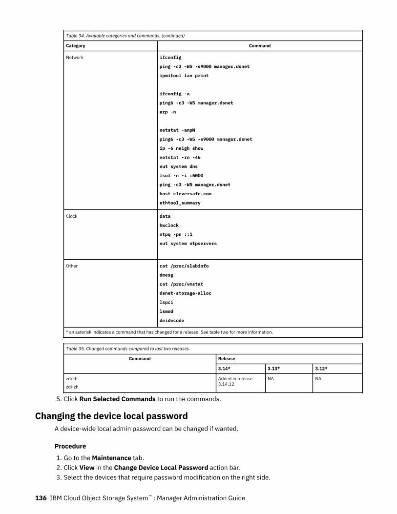
Table 34. Available categories and commands. (continued)
Category Command
Network ifconfig
ping -c3 -W5 -s9000 manager.dsnet
ipmitool lan print
ifconfig -a
ping6 -c3 -W5 manager.dsnet
arp -n
netstat -anpW
ping6 -c3 -W5 -s9000 manager.dsnet
ip -6 neigh show
netstat -rn -46
nut system dns
lsof -n -i :5000
ping -c3 -W5 manager.dsnet
host cleversafe.com
ethtool_summary
Clock data
hwclock
ntpq -pn ::1
nut system ntpservers
Other cat /proc/slabinfo
dmesg
cat /proc/vmstat
dsnet-storage-alloc
lspci
lsmod
dmidecode
* an asterisk indicates a command that has changed for a release. See table two for more information.
Table 35. Changed commands compared to last two releases.
Command Release
3.14* 3.13* 3.12*
zdi -h
zdi-zh
Added in release3.14.12
NA NA
5. Click Run Selected Commands to run the commands.
Changing the device local passwordA device-wide local admin password can be changed if wanted.
Procedure
1. Go to the Maintenance tab.2. Click View in the Change Device Local Password action bar.3. Select the devices that require password modification on the right side.
136 IBM Cloud Object Storage System™ : Manager Administration Guide
4. Enter the current password of the selected devices in the Current Password field.Devices that do not match this password will not have their password modified.
5. Enter the new password for the selected devices.6. Reenter the new password for the selected devices.7. Click Save.
Automatic report emailingConfigure automated system reports.
Under the Reports section of the Maintenance tab, click View to access Automatic Report Emailing. Thefollowing reports can be selected for automatic emailing:
• Disk Drive and Device Report• Storage Pool Capacity and Disk Report• System Usage and Configuration Summary Report• Storage Pool Usage Report• Vault Usage Report• Vault Summary Report• Device Summary Report• Failed FRU Report• Event Report• Firmware Report• Redaction Status Report (only visible when Configure management vault > Redact client information
is enabled)
Email addresses of individuals to receive the reports can be specified. Automatic report emailing can bescheduled for daily or weekly intervals. The times are in GMT.
Enter the following information and click Update or Cancel.
Reports
Select the reports, which are in HTML format with a .csv attachment.
Email Addresses
Enter the email addresses, which are separated by a comma or return.
Schedule
Enable Automatic reports, and select the report frequency.
ReportingReports can be emailed automatically or generated manually on demand.
Under the Reports section of the Maintenance tab, click View to access the reports.
Automatic Email
Configure the automatic report feature. The Administration SMTP Configuration must be configured to usethis feature.
Disk Drive and Devices
The Disk Drive and Device utility can be used to view disk parameters (model, serial number, softwareversion) for each disk in the system. [All parameters are not available for virtual devices.] Click Generateto create a report or click Export to download the default report as a Comma Separated Values file (.csv).
Storage Pool Capacity and Disk
Chapter 7. Maintenance 137
The Storage Pool Capacity and Disk utility can be used to view storage pool capacity. Click Generate tocreate a report or click Export to download the default report as a Comma Separated Values file (.csv).
System Usage and Configuration Summary
The System Usage And Configuration Summary can be used to generate a summary of organizations,storage usage, sites, storage pools information for this system. Click Generate to create a report or clickExport to download the default report as a Comma Separated Values file (.csv).
Vault Usage
Generate a report that shows vault usage over time. Click Generate to create a report or click Export todownload the default report as a Comma Separated Values file (.csv).
Vault Summary
Generate a report of all Vault configurations in the system. Click Generate to create a report or clickExport to download the default report as a Comma Separated Values file (.csv).
Device Summary
Generate a report of all Device configurations in the system. Click Generate to create a report or clickExport to download the default report as a Comma Separated Values file (.csv).
Failed FRUs
Generate a report of failed Field Replaceable Units (FRUs). Click Generate to create a report or clickExport to download the default report as a Comma Separated Values file (.csv).
Events
Generate a report of the Events. Click Generate to create a report or click Export to download the defaultreport as a Comma Separated Values file (.csv).
Firmware
Generate a report of device Firmware. Click Generate to create a report or click Export to download thedefault report as a Comma Separated Values file (.csv).
“Redaction status report” on page 146
If Cloud Mode is enabled, generate a report of redaction status.Click Generate to create a report or clickExport to download the default report as a Comma Separated Values file (.csv).
“Generating expiration scanning and reclamation for devices report” on page 141
Object Expiration Scanning and Reclamation for Devices Report.
“Generating expiration scanning and reclamation for storage pools report” on page 142
Object Expiration Scanning and Reclamation for Devices Report.
Generating disk drive and device reportsCreate a summary of disk information for all drives in the system.
About this task
The filter functions can be used to sort the data by relevant parameters, including Drive Status, DeviceAlias, Site, Cabinet, Device Model, Device Software Version, Block Device Name, Drive Model, andFirmware. More columns appear if a multi-node appliance exists in the system. The columns are ChassisID and Node Location and Node Count that describes the node configuration of a multi-node chassis. Forappliances that is not multi-node, the columns are marked 'N/A'. This information is view-only and cannotbe changed from this screen.
The contents can be filtered, based on items such as disk status and model, and exported to a .csv file.It can be used for troubleshooting disk and device health issues. The following information is available:
• Drive Status
138 IBM Cloud Object Storage System™ : Manager Administration Guide
• Suspend Reason• Block Device Name• RAID Sequence• Bay• Drive Serial number• Drive Model• Drive Firmware• Alias• IP Addresses• Device Serial number• Drive Usage• Model• Version• Cabinet (if present)• Slot number (if cabinet present)• Site• Pool• Chassis ID• Node Location• Node Count• Drive Capacity
Note: This report displays Bay identifiers with a new format:<chassisId>:<enclosureId>:<slotId>.
Procedure
1. Click View under the Reports section in the Maintenance tab to generate this report.2. Click Generate from the Disk Drive and Device Report action bar displays a list of all drives for all
devices within the system.3. Click Send to email or Export to create a .csv (comma-separated values) file for use with spreadsheet
applications.
Note: A reduced set of drive attributes are available for virtual devices. Bay number, drive serialnumber, drive model, and drive firmware appear as N/A.
Generating storage pool capacity and disk reportGenerate a report of system Storage Pool capacity and drive health.
About this task
The report displays a list of all storage pools with counts of different drive states and all the unhealthydrive information in a different table within the system.
The report contents can be searched by using the Search bar provided on top of each table. Storage poolscan be sorted based on the number of drives at a particular state. The entire report can be exported toa .csv file.
Note: This report displays Bay identifiers with a new format:<chassisId>:<enclosureId>:<slotId>.
Chapter 7. Maintenance 139
Procedure
1. Click View under the Reports section in the Maintenance tab to generate this report.2. Click Generate from the Storage Pool Capacity and Disk Report action bar.3. Select Storage Pool Capacity and Drive Health or Unhealthy Drives by Storage Pool.4. Click Send to email or Export to create a .csv (comma-separated values) report for use with
spreadsheet applications.
Report contents
In the first table of the report, the contents can be filtered based on items such as storage pool name andwidth. It can show general storage pool health.
The first table includes:
• Storage Pool ID• Storage Pool Name• Storage Pool Width• Storage Pool Total Size/ Capacity• Storage Pool Usage• Storage Pool Remaining free space• Percentage of Remaining Free space• Number of ONLINE drives• Number of MIGRATING drives• Number of FAILED drives• Number of DIAGNOSTIC drives• Number of FOREIGN drives• Number of OFFLINE drives• Number of UNUSABLE drives• Number of INIT drives• Number of UNKNOWN drives• Total Number of unhealthy drives• Total Number of drives
In the second table of the report, the contents can be filtered based on items such as storage pool name,host name, device model, drive status, suspend reason, drive model, and firmware.
It can be used for troubleshooting all the disk and device health issues in a storage pool.
The second table includes:
• Storage Pool Group Name• Host Name• Device Model• Drive Status• Suspend Reason• Bay number• Drive Capacity• Drive Serial Number• Block Device Name• Model• Firmware
140 IBM Cloud Object Storage System™ : Manager Administration Guide

Generating a vault usage reportThe Vault Usage Report generates a vault usage summary based on a date range (monthly or user-specified) for each vault.
About this task
Daily averages of the storage that is used by each vault are calculated. When a date range is selected, thesum of daily average usage in the range is displayed in PB/TB/GB/MB/kB days. When the content isexported, the number is converted to Byte-days that can be used for billing purposes. The report includesall the vaults (standard, service, container, and management) on the system irrespective of the vaultpurpose.
Storage that is used by each vault is shown as the sum of daily average usage for the days that areselected in tabular format. Each vault usage is displayed in "PB/TB/GB/MB/kB days". When the content isexported, the usage is converted to Byte-days.
The Search field can be used to dynamically search through the table for items that contain the searchinput. The Filter drop-down on the Storage Pool column can be used for filtering vaults that areassociated with the selected Storage Pool. Both of these operations are mutually exclusive.
The table can be sorted on columns Name, Usage, and Provisioning Code by clicking the associatedcolumn header.
Note: The From date is inclusive and the To date is exclusive. Usage is collected every day at midnightGMT. The Usage Reporting Start and the Usage Reporting End columns present data based on eitherthe user selected time zone or the default time zone (GMT).
Procedure
1. Select either the Month from the drop-down or provide a Date Range by using the From and To fieldsfor the report.
2. Click Send to email the report to an email address in .csv format.3. Click Export to download the report in .csv format.4. Click Cancel to get back to the previous page.
Generating expiration scanning and reclamation for devices reportThis report generates a summary of expiration statistics for both scanning and space reclamation basedon a date range specified for each object expiration enabled access device.
About this task
This report displays object expiration life cycle (Name Index Scanning and Space Reclamation) statisticsdaily for all object expiration enabled access devices in the system.
Both scanning and space reclamation have some common columns provides the following information:
• Date of the specified cycle run.• Hostname of the device.• Access pool that the device is deployed to.• Storage pool that the vault deployed to accesser device of specified access pool.• Site of the device.• Status of the specified cycle. Expected values are In progress or Done.• Run time in Hours of specified cycle.
Scanning only columns:
• Objects scanned in specified cycle.
Chapter 7. Maintenance 141
• Objects to delete are the identified objects marked for deletion in next space reclamation cycle by thedevice.
• Bytes to delete are the number of bytes marked for deletion in next space reclamation cycle.
Space reclamation only columns:
• Objects deleted in specified cycle.• Bytes deleted in specified cycle.• Objects marked as deleted can be skipped from current cycle due to following reasons and the counts
associated with them are displayed in the table.
– Not Found - Objects skipped because they are already deleted or not found.– Protected - Objects skipped because they are protected.– Policy change - Objects skipped as a new policy in effect.– Object I/O Error - Objects skipped due to I/O errors.
The Scanning and Space reclamation tables can be filtered on columns Access Pool, Storage Pool, Site,and Status by clicking the associated column header.
Note: Maximum duration allowed for this report is 2 weeks. The From and To dates are inclusive.
Procedure
1. Provide a Date Range by using the From and To fields for the report.2. Click Send to email or Export to create a .csv (comma-separated values) report for use with
spreadsheet applications.3. Click Export to download the report in .csv format.4. Click Cancel to get back to the previous page.
Generating expiration scanning and reclamation for storage pools reportThis report generates a summary of expiration statistics for both scanning and space reclamation basedon a date range specified for each object expiration-enabled storage pool.
About this task
This report displays object expiration life cycle (Name Index Scanning and Space Reclamation) statisticsdaily for all object expiration enabled storage pools in the system.
Both scanning and space reclamation have some common columns provides the following information:
• Date of the specified cycle run.• Storage pool that the vault deployed to accesser device of specified access pool.• Site of the device.• Status of the specified cycle, and expected values are In progress or Done.• Run time in Hours of specified cycle.
Scanning only columns:
• Total of all Objects scanned by the vaults in this storage pool.• Total of all Objects to delete are the identified objects marked for deletion in next space reclamation
cycle by the vaults in this storage pool.• Total of all Bytes to delete are the number of bytes marked for deletion in next space reclamation cycle
by the vaults in this storage pool.
Space reclamation only columns:
• Total of all Objects deleted in specified cycle by the vaults in this storage pool.• Total of all Bytes deleted in specified cycle by the vaults in this storage pool.
142 IBM Cloud Object Storage System™ : Manager Administration Guide
• Total of all objects marked as deleted can be skipped from current cycle by the vaults in this storagepool due to following reasons and the counts associated with it are displayed in the table.
– Not Found - Objects skipped because they are already deleted or not found– Protected - Objects skipped because they are protected.– Policy change - Objects skipped as a new policy in effect.– Object I/O Error - Objects skipped due to I/O errors.
The Scanning and Space reclamation tables can be filtered on columns Storage Pool, Site, and Status byclicking the associated column header.
Note: Maximum duration allowed for this report is 6 months. The From and To dates are inclusive.
Procedure
1. Provide a Date Range by using the From and To fields for the report.2. Click Send to email or Export to create a .csv (comma-separated values) report for use with
spreadsheet applications.3. Click Export to download the report in .csv format.4. Click Cancel to get back to the previous page.
Vault summary reportThe Vault Summary Report can export the following data for all vaults to a .csv file:
• Vault ID• Name• Type• Description• Creation Date• Storage Pool• Retention• Vault Configuration
– Threshold– Read Threshold– Write Threshold– Alert Level
• SecureSlice™
• Segment Size• Vault Usage
– Raw Used– Usable Used– Usable Capacity
• Soft/Hard Quotas• Versioning• Notification Service• Notification Service Configured Topic• Notification Service Custom Topic• Container Storage Location
– Storage Location ID
Chapter 7. Maintenance 143
– Provisioning Code– Region– Storage Class
Click Send to email or Export to create a .csv (comma-separated values) report for use with spreadsheetapplications. The report can be filtered on some parameters. The default is ALL vaults.
Reporting device summaryGenerate a report of all Device configurations in the system.
About this task
The Device Summary Report can export the following data for all devices to a .csv file:
• Alias• Host name• IP address• Site• Type• Software Version• Model• Serial Number• MAC0(eth0)• MAC1(eth1)• Extra MAC Addresses• Pool• Device ID
Procedure
1. Click Send to email the report.2. Click Export to create a .csv (comma-separated values) report for use with spreadsheet applications.
The report can be filtered by using parameters. The default is ALL devices.
Failed FRU reportThe Failed FRU Report identifies all failed drives, power supplies, and fans. The report can be filtered onsome parameters. Default is ALL failures.
Note: The report shows any drive that is in the 'Failed' state, which means the drive should be replaced.
The failing of a drive covers these scenarios:
• A previously quarantined drive that is now in the FAILED state.• Reset for drives in the UNUSABLE state.• If the reset is successful, the drive is put in the ONLINE state.• If the reset fails, the drive is put in the FAILED state.• If system detects a previously failed drive, it puts the drive in the FAILED state.
All the failed drives, failed fans, and failed PSUs appear for replacement in the FRU Report.
The Failed FRU Report can be exported to a .csv file with the following format:
• Failed Drives• Device
144 IBM Cloud Object Storage System™ : Manager Administration Guide
• Model• Firmware• Serial• Capacity• Bay• Sequence• Device Model• Version• Device Serial #• Site• Failed Fans• Device• Model• Fan Name• Chassis ID of Fan• Chassis Serial of Fan• Failed PSUs• Device• Model• PSU Name• Chassis ID of PSU• Chassis Serial of PSU
Note: This report displays Bay identifiers with a new format:<chassisId>:<enclosureId>:<slotId>.
Click Send to email or Export to create a .csv (comma-separated values) report for use with spreadsheetapplications.
Reporting event informationGenerate a report of system events.
About this task
An Event Report can send all system events via email or .csv file. The Advanced Search can be used tofilter out events in the console before you send/export its contents. The link is in the upper right of theconsole.
Filtered Events are applicable when the report is emailed or exported. For example, if advanced search isbeing performed and only incidents are showing in the UI page and then export or email of the report isperformed, the items in the export/email match what is seen on the UI. Automated emails for the EventReport contain all log messages, all incidents, and contain event information from the past 7 days.
Note: The exported or emailed content is limited to a maximum of 50,000 items.
Procedure
1. Click the Maintenance tab.2. Click View on the Reports action bar.3. Configure the report with Advanced Search filters.4. Click Send to send the report by email.5. Click Export to generate a .csv file for use in spreadsheet applications.
Chapter 7. Maintenance 145
Method Action
Send via email Click Send in the action bar.
Export CSV Click Export in the action bar.
Firmware reportA firmware report is a firmware summary of each device. It includes device BIOS/BMC, network, diskcontroller, and disk drive firmware.
Method Action
Send via email Click Send in the action bar.
Export CSV Click Exportin the action bar.
Redaction status reportThis report outlines the redaction status for logs persisted to a management vault. The content can beexported to CSV format and sent by email.
Note: This report is only available if Configure management vault > Redact client information isenabled.
A device’s rotated access logs get uploaded to its management vault.
The system will be redacting client information at least X days after an access log was rotated. Xrepresents the access log redaction time, which is relative to when the access logs were rotated and canbe configured on the Configure Management Vault page.
All access logs that rotated on or before the access log redaction reference date are eligible for redaction.This date is calculated by using today’s date minus the access log redaction time.
The difference between the access log redaction reference date and the column Redacted Up To Date isthe value in the column Redaction Lag.
The report provides the following information per management vault:
• The Vault name.• The Storage Pool name of the vault.• The Redacted Up To Date of the vault. For a given date in the column Redacted Up To Date, all access
logs that rotated on or before that date have been redacted within the associated management vault.• The Redaction Lag in days. For a given value in the column Redaction Lag, a value of 0 implies
redaction is progressing as expected. A value greater than 0 may imply the system is not keeping upwith its redaction task, but does not necessarily mean that there is a problem. If the value exceedsexpectations when considering the number of access logs in the management vault, check the health ofthe system or contact Customer Support."
Note:
• The reaction status report can have its "Redacted Up To" date move backwards in time.• The redaction status will report "Initializing" for a period of time after enabling the feature and after
adding devices into the system."
Method Action
Send by email Click Send in the action bar.
Export CSV Click Export in the action bar.
146 IBM Cloud Object Storage System™ : Manager Administration Guide

Post login message
About this task
Through the Maintenance tab, an administrator can configure a post-login message to be displayed onthe system landing page for all users on the system.
Procedure
Click Configure on the Post Login Message action bar to navigate to the Post login message page.This page allows a message to be seen on the system landing page. A global message is seen by all users.
Chapter 7. Maintenance 147
Notices
This information was developed for products and services offered in the US. This material might beavailable from IBM in other languages. However, you may be required to own a copy of the product orproduct version in that language in order to access it.
IBM may not offer the products, services, or features discussed in this document in other countries.Consult your local IBM representative for information on the products and services currently available inyour area. Any reference to an IBM product, program, or service is not intended to state or imply that onlythat IBM product, program, or service may be used. Any functionally equivalent product, program, orservice that does not infringe any IBM intellectual property right may be used instead. However, it is theuser's responsibility to evaluate and verify the operation of any non-IBM product, program, or service.
IBM may have patents or pending patent applications covering subject matter described in thisdocument. The furnishing of this document does not grant you any license to these patents. You can sendlicense inquiries, in writing, to:
IBM Director of LicensingIBM CorporationNorth Castle DriveArmonk, NY 10504-1785U.S.A.
For license inquiries regarding double-byte character set (DBCS) information, contact the IBM IntellectualProperty Department in your country or send inquiries, in writing, to:
Intellectual Property LicensingLegal and Intellectual Property LawIBM Japan, Ltd.19-21, Nihonbashi-Hakozakicho, Chuo-kuTokyo 103-8510, Japan
INTERNATIONAL BUSINESS MACHINES CORPORATION PROVIDES THIS PUBLICATION "AS IS"WITHOUT WARRANTY OF ANY KIND, EITHER EXPRESS OR IMPLIED, INCLUDING, BUT NOT LIMITED TO,THE IMPLIED WARRANTIES OF NON-INFRINGEMENT, MERCHANTABILITY OR FITNESS FOR APARTICULAR PURPOSE. Some jurisdictions do not allow disclaimer of express or implied warranties incertain transactions, therefore, this statement may not apply to you.
This information could include technical inaccuracies or typographical errors. Changes are periodicallymade to the information herein; these changes will be incorporated in new editions of the publication.IBM may make improvements and/or changes in the product(s) and/or the program(s) described in thispublication at any time without notice.
Any references in this information to non-IBM websites are provided for convenience only and do not inany manner serve as an endorsement of those websites. The materials at those websites are not part ofthe materials for this IBM product and use of those websites is at your own risk.
IBM may use or distribute any of the information you provide in any way it believes appropriate withoutincurring any obligation to you.
Licensees of this program who wish to have information about it for the purpose of enabling: (i) theexchange of information between independently created programs and other programs (including thisone) and (ii) the mutual use of the information which has been exchanged, should contact:
IBM Director of LicensingIBM CorporationNorth Castle Drive, MD-NC119Armonk, NY 10504-1785
148 Notices

US
Such information may be available, subject to appropriate terms and conditions, including in some cases,payment of a fee.
The licensed program described in this document and all licensed material available for it are provided byIBM under terms of the IBM Customer Agreement, IBM International Program License Agreement or anyequivalent agreement between us.
The performance data discussed herein is presented as derived under specific operating conditions.Actual results may vary.
Information concerning non-IBM products was obtained from the suppliers of those products, theirpublished announcements or other publicly available sources. IBM has not tested those products andcannot confirm the accuracy of performance, compatibility or any other claims related to non-IBMproducts. Questions on the capabilities of non-IBM products should be addressed to the suppliers ofthose products.
Statements regarding IBM's future direction or intent are subject to change or withdrawal without notice,and represent goals and objectives only.
All IBM prices shown are IBM's suggested retail prices, are current and are subject to change withoutnotice. Dealer prices may vary.
This information is for planning purposes only. The information herein is subject to change before theproducts described become available.
This information contains examples of data and reports used in daily business operations. To illustratethem as completely as possible, the examples include the names of individuals, companies, brands, andproducts. All of these names are fictitious and any similarity to the names and addresses used by anactual business enterprise is entirely coincidental.
COPYRIGHT LICENSE:
This information contains sample application programs in source language, which illustrate programmingtechniques on various operating platforms. You may copy, modify, and distribute these sample programsin any form without payment to IBM, for the purposes of developing, using, marketing or distributingapplication programs conforming to the application programming interface for the operating platform forwhich the sample programs are written. These examples have not been thoroughly tested under allconditions. IBM, therefore, cannot guarantee or imply reliability, serviceability, or function of theseprograms. The sample programs are provided "AS IS", without warranty of any kind. IBM shall not beliable for any damages arising out of your use of the sample programs.
If you are viewing this information softcopy, the photographs and color illustrations may not appear.
TrademarksIBM, the IBM logo, and ibm.com® are trademarks or registered trademarks of International BusinessMachines Corp., registered in many jurisdictions worldwide. Other product and service names might betrademarks of IBM or other companies. A current list of IBM trademarks is available on the web atCopyright and trademark information at www.ibm.com/legal/copytrade.shtml.
Accesser®, Cleversafe®, ClevOS™, Dispersed Storage®, dsNet®, IBM Cloud Object Storage Accesser®, IBMCloud Object Storage Dedicated™, IBM Cloud Object Storage Insight™, IBM Cloud Object StorageManager™, IBM Cloud Object Storage Slicestor®, IBM Cloud Object Storage Standard™, IBM Cloud ObjectStorage System™, IBM Cloud Object Storage Vault™, SecureSlice™, and Slicestor® are trademarks orregistered trademarks of Cleversafe, an IBM Company and/or International Business Machines Corp.
Other product and service names might be trademarks of IBM or other companies.
Notices 149
Homologation statementThis product may not be certified in your country for connection by any means whatsoever to interfaces ofpublic telecommunications networks. Further certification may be required by law prior to making anysuch connection. Contact an IBM representative or reseller for any questions.
150 IBM Cloud Object Storage System™ : Manager Administration Guide


IBM®
Printed in USA