Embed Size (px)
Citation preview

DSP 26digital speaker
management system
user manual

Musikhaus Thomann
Thomann GmbH
Hans-Thomann-Straße 1
96138 Burgebrach
Germany
Telephone: +49 (0) 9546 9223-0
E-mail: [email protected]
Internet: www.thomann.de
07.01.2016, ID: 341074

Table of contents
1 General notes............................................................................................................................................... 51.1 Further information........................................................................................................................... 61.2 Notational conventions.................................................................................................................... 71.3 Symbols and signal words............................................................................................................... 8
2 Safety notes............................................................................................................................................... 10
3 Features....................................................................................................................................................... 14
4 Installation and starting up................................................................................................................ 15
5 Connections and controls................................................................................................................... 16
6 Operating.................................................................................................................................................... 216.1 UTILITY menu.................................................................................................................................... 226.2 INPUT A/B menu............................................................................................................................... 346.3 OUTPUT 1/2/3/4/5/6 menu.......................................................................................................... 386.4 Channel linkage................................................................................................................................ 456.5 Reset to factory defaults................................................................................................................ 46
7 Technical specifications....................................................................................................................... 47
Table of contents
DSP 26
3
8 Plug and connection assignment.................................................................................................... 49
9 Cleaning....................................................................................................................................................... 51
10 Protecting the environment.............................................................................................................. 52
Table of contents
digital speaker management system
4
1 General notes
This manual contains important instructions for the safe operation of the unit. Read and followthe safety instructions and all other instructions. Keep the manual for future reference. Makesure that it is available to all those using the device. If you sell the unit please make sure thatthe buyer also receives this manual.
Our products are subject to a process of continuous development. Thus, they are subject tochange.
General notes
DSP 26
5

1.1 Further information
On our website (www.thomann.de) you will find lots of further information and details on thefollowing points:
Download This manual is also available as PDF file for you to download.
Keyword search Use the search function in the electronic version to find the topics ofinterest for you quickly.
Online guides Our online guides provide detailed information on technical basicsand terms.
Personal consultation For personal consultation please contact our technical hotline.
Service If you have any problems with the device thecustomer service will gladly assist you.
General notes
digital speaker management system
6

1.2 Notational conventions
This manual uses the following notational conventions:
The letterings for connectors and controls are marked by square brackets and italics.
Examples: [VOLUME] control, [Mono] button.
Texts and values displayed on the device are marked by quotation marks and italics.
Examples: ‘24ch’ , ‘OFF’ .
References to other locations in this manual are identified by an arrow and the specified pagenumber. In the electronic version of the manual, you can click the cross-reference to jump tothe specified location.
Example: See Ä ‘Cross-references’ on page 7.
Letterings
Displays
Cross-references
General notes
DSP 26
7
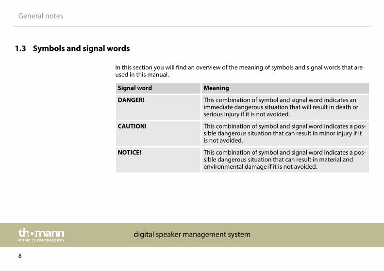
1.3 Symbols and signal words
In this section you will find an overview of the meaning of symbols and signal words that areused in this manual.
Signal word Meaning
DANGER! This combination of symbol and signal word indicates animmediate dangerous situation that will result in death orserious injury if it is not avoided.
CAUTION! This combination of symbol and signal word indicates a pos‐sible dangerous situation that can result in minor injury if itis not avoided.
NOTICE! This combination of symbol and signal word indicates a pos‐sible dangerous situation that can result in material andenvironmental damage if it is not avoided.
General notes
digital speaker management system
8
Warning signs Type of danger
Warning – high-voltage.
Warning – danger zone.
General notes
DSP 26
9

2 Safety notes
This device serves sound control and distribution of incoming audio signals to the connectedspeakers. Use the device only as described in this user manual. Any other use or use underother operating conditions is considered to be improper and may result in personal injury orproperty damage. No liability will be assumed for damages resulting from improper use.
This device may be used only by persons with sufficient physical, sensorial, and intellectualabilities and having corresponding knowledge and experience. Other persons may use thisdevice only if they are supervised or instructed by a person who is responsible for their safety.
DANGER!Danger for childrenEnsure that plastic bags, packaging, etc. are disposed of properly and are notwithin reach of babies and young children. Choking hazard!
Ensure that children do not detach any small parts (e.g. knobs or the like) fromthe unit. They could swallow the pieces and choke!
Never let children unattended use electrical devices.
Intended use
Safety
Safety notes
digital speaker management system
10
DANGER!Electric shock caused by high voltages insideWithin the device there are areas where high voltages may be present. Neverremove any covers.
There are no user-serviceable parts inside.
DANGER!Electric shock caused by short-circuitAlways use proper ready-made insulated mains cabling (power cord) with a pro‐tective contact plug. Do not modify the mains cable or the plug. Failure to do socould result in electric shock/death or fire. If in doubt, seek advice from a regis‐tered electrician.
Safety notes
DSP 26
11
CAUTION!Possible hearing damageWith loudspeakers or headphones connected, the device can produce volumelevels that may cause temporary or permanent hearing impairment.
Do not operate the device permanently at a high volume level. Decrease thevolume level immediately if you experience ringing in your ears or hearingimpairment.
NOTICE!Risk of fireDo not cover the device nor any ventilation slots. Do not place the device nearany direct heat source. Keep the device away from naked flames.
Safety notes
digital speaker management system
12

NOTICE!Operating conditionsThis device has been designed for indoor use only. To prevent damage, neverexpose the device to any liquid or moisture. Avoid direct sunlight, heavy dirt, andstrong vibrations.
NOTICE!Power supplyBefore connecting the device, ensure that the input voltage (AC outlet) matchesthe voltage rating of the device and that the AC outlet is protected by a residualcurrent circuit breaker. Failure to do so could result in damage to the device andpossibly injure the user.
Unplug the device before electrical storms occur and when it is unused for longperiods of time to reduce the risk of electric shock or fire.
Safety notes
DSP 26
13
3 Features
n Two input channelsn Six output channelsn Digital 24-bit signal processorsn RS485 interfacen USB portn Suitable for installation in 19-inch racks (1 RU)
Features
digital speaker management system
14

4 Installation and starting up
Unpack and carefully check that there is no transportation damage before using the unit. Keepthe equipment packaging. To fully protect the device against vibration, dust and moistureduring transportation or storage use the original packaging or your own packaging materialsuitable for transport or storage, respectively.
Establish all connections as long as the unit is switched off. Use the shortest possible high-quality cables for all connections.
The unit has been designed for rack mounting in a standard 19-inch rack; it occupies one rackunit.
Rack mounting
Installation and starting up
DSP 26
15
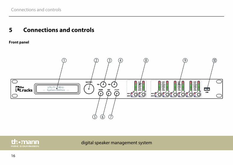
5 Connections and controls
Front panel
Connections and controls
digital speaker management system
16
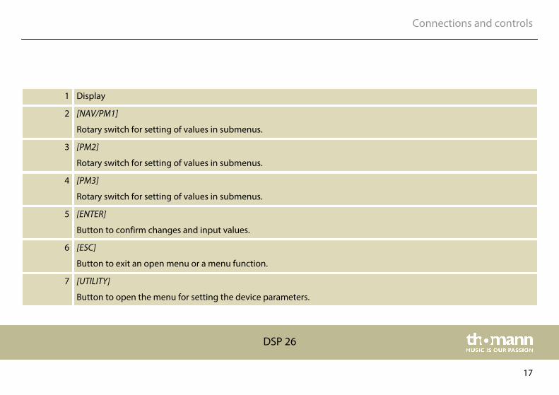
1 Display
2 [NAV/PM1]
Rotary switch for setting of values in submenus.
3 [PM2]
Rotary switch for setting of values in submenus.
4 [PM3]
Rotary switch for setting of values in submenus.
5 [ENTER]
Button to confirm changes and input values.
6 [ESC]
Button to exit an open menu or a menu function.
7 [UTILITY]
Button to open the menu for setting the device parameters.
Connections and controls
DSP 26
17
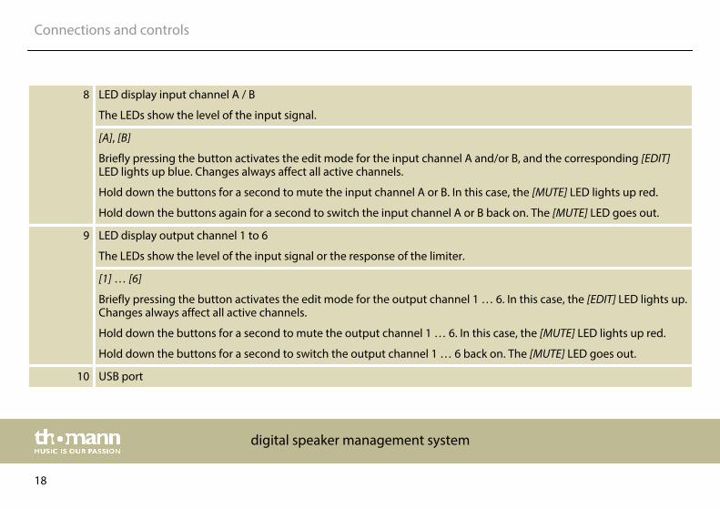
8 LED display input channel A / B
The LEDs show the level of the input signal.
[A], [B]
Briefly pressing the button activates the edit mode for the input channel A and/or B, and the corresponding [EDIT]LED lights up blue. Changes always affect all active channels.
Hold down the buttons for a second to mute the input channel A or B. In this case, the [MUTE] LED lights up red.
Hold down the buttons again for a second to switch the input channel A or B back on. The [MUTE] LED goes out.
9 LED display output channel 1 to 6
The LEDs show the level of the input signal or the response of the limiter.
[1] … [6]
Briefly pressing the button activates the edit mode for the output channel 1 … 6. In this case, the [EDIT] LED lights up.Changes always affect all active channels.
Hold down the buttons for a second to mute the output channel 1 … 6. In this case, the [MUTE] LED lights up red.
Hold down the buttons for a second to switch the output channel 1 … 6 back on. The [MUTE] LED goes out.
10 USB port
Connections and controls
digital speaker management system
18
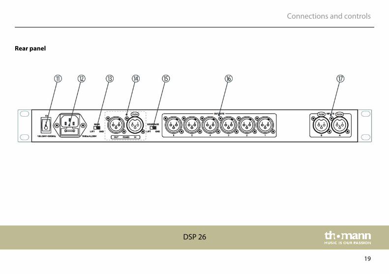
Rear panel
Connections and controls
DSP 26
19
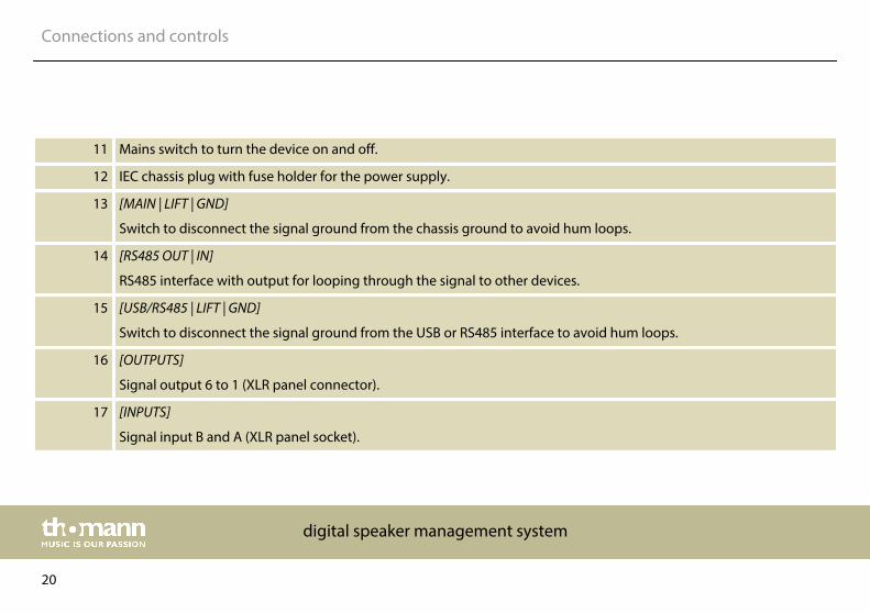
11 Mains switch to turn the device on and off.
12 IEC chassis plug with fuse holder for the power supply.
13 [MAIN | LIFT | GND]
Switch to disconnect the signal ground from the chassis ground to avoid hum loops.
14 [RS485 OUT | IN]
RS485 interface with output for looping through the signal to other devices.
15 [USB/RS485 | LIFT | GND]
Switch to disconnect the signal ground from the USB or RS485 interface to avoid hum loops.
16 [OUTPUTS]
Signal output 6 to 1 (XLR panel connector).
17 [INPUTS]
Signal input B and A (XLR panel socket).
Connections and controls
digital speaker management system
20

6 Operating
First switch on the speaker management system and then switch on the connecteddevices to avoid activation crackling and possible damage to the connected speakers.
When the device is switched on, the model name, the start-up status, and the last active oper‐ating mode (default: ‘2×3 WAY X-OVER’ ) appear one after another in the display.
Afterwards, there is the option to activate a desired operating mode or to adjust the devicesettings.
Operating
DSP 26
21

6.1 UTILITY menu
Press [UTILIY] to enter the ‘UTILITY’ menu. Select the required submenu with[NAV/PM1] andconfirm with [ENTER].
Select the required option in the open submenu with[NAV/PM1] and confirm with [ENTER]. Theselected menu item is marked with an asterisk (*).
Adjust the settings with [PM2] or [PM3] and confirm by pressing [ENTER] to apply the new set‐tings.
Pressing [ESC] exits the menu without applying changes.
Operating
digital speaker management system
22
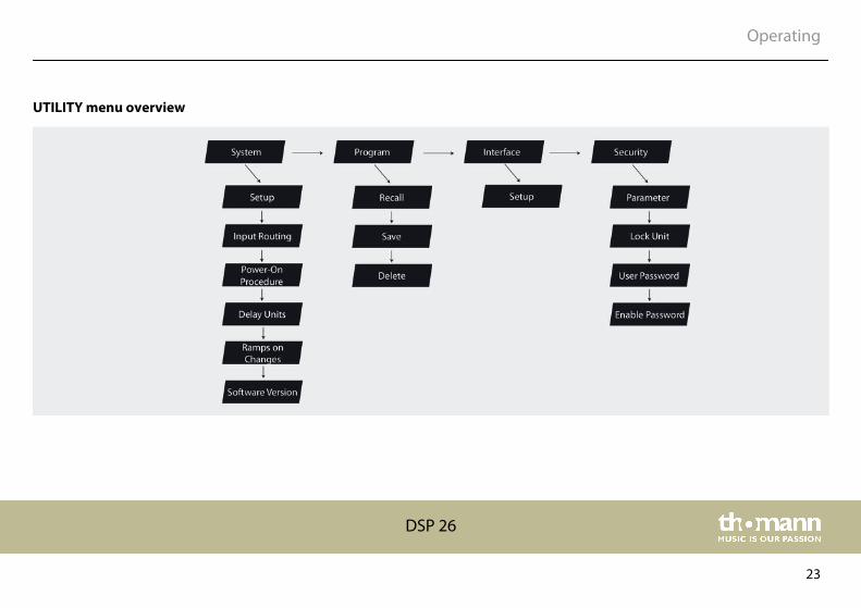
UTILITY menu overview
Operating
DSP 26
23

This menu is used to select the operating mode. In the [UTILITY] menu, select the ‘SystemUtilities’ option and confirm with [ENTER].
Select the ‘System Setup’ menu item and confirm with [ENTER]. The active operating mode isshown on the display.
Select the required operating mode with [PM2] or [PM3] and confirm by pressing [ENTER] toapply the new setting.
Operating modes
n ‘2 × 2 WAY + SUB’ – in this operating mode, two inputs are assigned to four outputs asfollows:– Input A to output 1/3 (1 = Low-A, 3 = High-A)– Input B to output 2/4 (2 = Low-B, 4 = High-B)– Input A and B to output 5/6 (5 = Sub-A, 6 = Sub-B)
n ‘2 × 3 WAY.XOVER’ – in this operating mode, two inputs are assigned to six outputs as fol‐lows:– Input A to output 1/3/5 (1 = Low-A, 3 = Mid-A, 5 = High-A)– Input B to output 2/4/6 (2 = Low-B, 4 = Mid-B, 6 = High-B)
n ‘6 WAY.XOVER’ – in this operating mode, input A is assigned to six outputs as follows:– Input A to output 1/2/3/4/5/6 (1 = Near-1, 2 = Near-2, 3 = Mid-1, 4 = Mid-2, 5 = Far-1, 6
= Far-2)
"System Utilities" – "SystemSetup"
Operating
digital speaker management system
24
Pressing [ESC] exits the menu without applying changes.
This menu is used to set the signal delay of the digital speaker management system. In the[UTILITY] menu, select the ‘System Utilities’ option and confirm with [ENTER].
Select the ‘Delay Units’ menu item and confirm with [ENTER]. The display shows the currentsetting.
Press [PM2] or [PM3] to switch between the available units of meters (m) and milliseconds (ms).
Turn [PM2] or [PM3] to set the unit required and confirm by pressing [ENTER] to apply the newsetting.
Pressing [ESC] exits the menu without applying changes.
This menu item is used to display the currently loaded software version. In the [UTILITY] menu,select the ‘System Utilities’ option and confirm with [ENTER].
Select the ‘Software Version’ menu item and confirm with [ENTER]. The display shows the cur‐rent software version
"System Utilities" – "DelayUnits"
"System Utilities" - "SoftwareVersion"
Operating
DSP 26
25
This menu is used to load stored configurations. A total of 24 storage locations are available forconfigurations. In the [UTILITY] menu, select the ‘Program Utilities’ option and confirm with[ENTER].
Select the ‘Recall a Program’ menu item and confirm with [ENTER].
Select the required entry with [PM2] or [PM3] and confirm by pressing [ENTER] to apply thenew setting.
If there are no configurations stored on the device, the message ‘No Stored Xovers’ is dis‐played.
Press [ESC] to cancel the operation at any time.
"Program Utilities" - "Recall aProgram"
Operating
digital speaker management system
26

This menu is used to save current device settings as a configuration. A total of 24 storage loca‐tions are available for configurations. In the [UTILITY] menu, select the ‘Program Utilities’ optionand confirm with [ENTER].
Select the ‘Save a Program’ menu item and confirm with [ENTER].
Select the required storage location with [PM2] or [PM3] and confirm by pressing [ENTER].Existing records can be overwritten. In this case, a corresponding confirmation promptappears on the display. Press [ENTER] to confirm that the settings should be overwritten.
The following screen is used to enter a name under which the configuration is to be stored (upto 16 characters). Enter letters and numbers with [PM2] or [PM3]. The cursor can be placed inany position with [NAV/PM1], for example to overwrite a character that has been entered incor‐rectly.
Use [ENTER] to confirm that the configuration is to be stored under the new name.
Press [ESC] to cancel the operation at any time.
"Program Utilities" - "Save a Pro‐gram"
Operating
DSP 26
27
This menu is used to delete stored configurations. In the [UTILITY] menu, select the ‘ProgramUtilities’ option and confirm with [ENTER].
Select the ‘Delete a Program’ menu item and confirm with [ENTER].
Highlight the configuration to be deleted with [PM2] or [PM3]. Confirm with [ENTER].
A corresponding confirmation prompt appears on the display. Press [ENTER] to confirm thatthe settings should be deleted.
Press [ESC] to cancel the operation at any time.
"Program Utilities" - "Delete aProgram"
Operating
digital speaker management system
28

This menu is used to define which interface is used to control the device.
In the [UTILITY] menu, select the ‘Interface Utilities’ option and confirm with [ENTER].
Select the ‘Interface Setup’ menu item and confirm with [ENTER]. The display shows the currentsetting.
Switch between the two available options with [PM2] or [PM3] and confirm by pressing [ENTER]to apply the new setting.
Interface
n ‘USB’ - This selection establishes a connection to an external device via the USB interface.n ‘RS485’ - This selection establishes a connection to an external device via the RS485 inter‐
face
Pressing [ESC] exits the menu without applying changes.
"Interface Utilities" - "InterfaceSetup"
Operating
DSP 26
29
This menu is used to define if the device parameters are displayed or hidden.
In the [UTILITY] menu, select the ‘Security Utilities’ option and confirm with [ENTER].
Select the ‘Show Parameter’ menu item and confirm with [ENTER]. The display shows the cur‐rent setting.
Switch between the available options with [PM2] or [PM3] and confirm by pressing [ENTER] toapply the new setting.
Parameter display
n ‘Parameter will be shown’ – This selection displays all device parameters.n ‘Parameter will not be shown’ – This selection hides all device parameters.
Pressing [ESC] exits the menu without applying changes.
"Security Utilities" - "ShowParameter"
Operating
digital speaker management system
30

This menu is used to define the access rights to the different device parameters.
In the [UTILITY] menu, select the ‘Security Utilities’ option and confirm with [ENTER].
Select the ‘Lock Unit’ menu item and confirm with [ENTER]. The display shows the current set‐ting.
Switch between the available options with [PM2] or [PM3] and confirm by pressing [ENTER] toapply the new setting.
Parameter access
n ‘Lock: Off’ - With this selection, all device parameters can be edited without entering apassword.
n ‘Lock: On’ - With this selection, the device parameters can only be accessed after enteringa valid password.
Pressing [ESC] exits the menu without applying changes.
"Security Utilities" – "Lock Unit"
Operating
DSP 26
31
This menu is used to set a password to control access to the different device parameters.
In the [UTILITY] menu, select the ‘Security Utilities’ option and confirm with [ENTER].
Select the ‘User Password’ menu item and confirm with [ENTER]. The ‘Insert Password’ promptappears on the display.
Use [PM2] or [PM3] to enter a password with a maximum of six characters. The cursor can beplaced in any position with [NAV/PM1], for example to overwrite a character that has beenentered incorrectly.
Confirm the input with [ENTER]. The ‘Confirm Password’ prompt appears on the display. Retypethe password for confirmation and confirm with [ENTER], to finally accept the password.
Pressing [ESC] exits the menu without applying changes.
"Security Utilities" - "User Pass‐word"
Operating
digital speaker management system
32

This menu is used to activate or deactivate the password protection of the device.
In the [UTILITY] menu, select the ‘Security Utilities’ option and confirm with [ENTER].
Select the ‘Enable Password’ menu item and confirm with [ENTER]. The display shows the cur‐rent setting.
Switch between the available options with [PM2] or [PM3] and confirm by pressing [ENTER] toapply the new setting.
Password protection
n ‘Password: Enable’ - With this selection, the device parameters can only be accessed afterentering a valid password.
n ‘Password: Disable’ - With this selection, all device parameters can be edited withoutentering a password.
Pressing [ESC] exits the menu without applying changes.
"Security Utilities" - "EnablePassword"
Operating
DSP 26
33
6.2 INPUT A/B menu
Press [A] or [B] to activate the edit mode for channel A or B and to open the ‘INPUT A/B’ menu.On the device, the [EDIT] display LED of the activated input channel A or B lights up blue. Press[ENTER]. An arrow is shown on the display. The individual input parameters can now beadjusted.
Changes always affect all active input channels.
Select the required option with[NAV/PM1] and confirm with [ENTER]. The selected menu item ismarked with an asterisk (*).
Adjust the settings with [PM2] or [PM3] and confirm by pressing [ENTER] to apply the new set‐tings.
Pressing [ESC] exits the menu without applying changes.
Operating
digital speaker management system
34

INPUT A/B menu overview
Operating
DSP 26
35

This menu is used to lower or raise the level of the input signal in a range of –12 dB to +12 dB.Press [A] or [B] to activate the edit mode for channel A or B and to open the ‘INPUT A/B’ menu.
Use [PM2] or [PM3] to adjust the level of the input signal as required. Confirm the new settingwith [ENTER].
Pressing [ESC] exits the menu without applying changes.
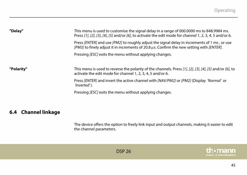
This menu is used to customise the signal delay in a range of 000.0000 ms to 848.9984 ms.Press [A] or [B] to open the ‘INPUT A/B’ menu.
Press [ENTER] and use [PM2] to roughly adjust the signal delay in increments of 1 ms , or use[PM3] to finely adjust it in increments of 20.8 ms. Confirm the new setting with [ENTER].
Pressing [ESC] exits the menu without applying changes.
"Gain"
"Delay"
Operating
digital speaker management system
36
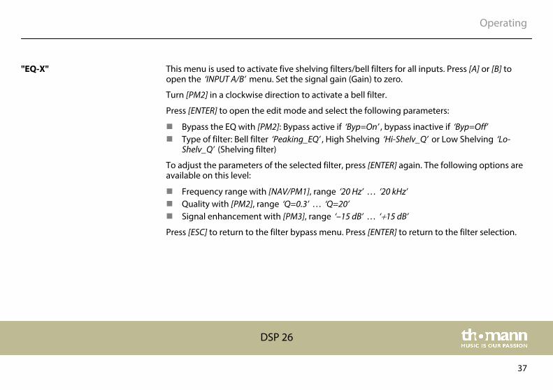
This menu is used to activate five shelving filters/bell filters for all inputs. Press [A] or [B] toopen the ‘INPUT A/B’ menu. Set the signal gain (Gain) to zero.
Turn [PM2] in a clockwise direction to activate a bell filter.
Press [ENTER] to open the edit mode and select the following parameters:
n Bypass the EQ with [PM2]: Bypass active if ‘Byp=On’ , bypass inactive if ‘Byp=Off’n Type of filter: Bell filter ‘Peaking_EQ’ , High Shelving ‘Hi-Shelv_Q’ or Low Shelving ‘Lo-
Shelv_Q’ (Shelving filter)
To adjust the parameters of the selected filter, press [ENTER] again. The following options areavailable on this level:
n Frequency range with [NAV/PM1], range ‘20 Hz’ … ‘20 kHz’n Quality with [PM2], range ‘Q=0.3’ … ‘Q=20’n Signal enhancement with [PM3], range ‘–15 dB’ … ‘+15 dB’
Press [ESC] to return to the filter bypass menu. Press [ENTER] to return to the filter selection.
"EQ-X"
Operating
DSP 26
37

6.3 OUTPUT 1/2/3/4/5/6 menu
Press [1], [2], [3], [4], [5] and/or [6], to activate the edit mode for channel 1, 2, 3, 4, 5 and/or 6and open the ‘OUTPUT 1/2/3/4/5/6’ menu. On the device, the [EDIT] display LED of the acti‐vated output channel lights up blue. Press [ENTER]. An arrow is shown on the display. The indi‐vidual output parameters can now be adjusted.
Select the required option with[NAV/PM1] and confirm with [ENTER]. The selected menu item ismarked with an asterisk (*).
Adjust the settings with [PM2] or [PM3] and confirm by pressing [ENTER] to apply the new set‐tings.
Pressing [ESC] exits the menu without applying changes.
Operating
digital speaker management system
38
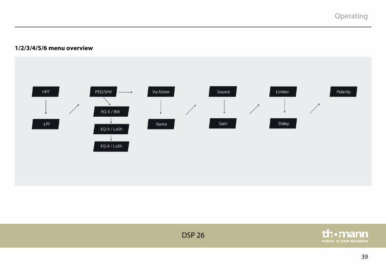
1/2/3/4/5/6 menu overview
Operating
DSP 26
39
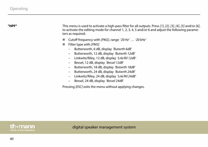
This menu is used to activate a high-pass filter for all outputs. Press [1], [2], [3], [4], [5] and/or [6],to activate the editing mode for channel 1, 2, 3, 4, 5 and/or 6 and adjust the following parame‐ters as required:
n Cutoff frequency with [PM2], range ‘20 Hz’ … ‘20 kHz’n Filter type with [PM3]
– Butterworth, 6 dB, display ‘Butwrth 6dB’– Butterworth, 12 dB, display ‘Butwrth 12dB’– Linkwitz/Riley, 12 dB, display ‘Lnk/Ril 12dB’– Bessel, 12 dB, display ‘Bessel 12dB’– Butterworth, 18 dB, display ‘Butwrth 18dB’– Butterworth, 24 dB, display ‘Butwrth 24dB’– Linkwitz/Riley, 24 dB, display ‘Lnk/Ril 24dB’– Bessel, 24 dB, display ‘Bessel 24dB’
Pressing [ESC] exits the menu without applying changes.
"HPF"
Operating
digital speaker management system
40

This menu is used to activate a low-pass filter for all outputs. Press [1], [2], [3], [4], [5] and/or [6],to activate the editing mode for channel 1, 2, 3, 4, 5 and/or 6 and adjust the following parame‐ters as required:
n Cutoff frequency with [PM2], range ‘20 Hz’ … ‘20 kHz’n Filter type with [PM3]
– Butterworth, 6 dB, display ‘Butwrth 6dB’– Butterworth, 12 dB, display ‘Butwrth 12dB’– Linkwitz/Riley, 12 dB, display ‘Lnk/Ril 12dB’– Bessel, 12 dB, display ‘Bessel 12dB’– Butterworth, 18 dB, display ‘Butwrth 18dB’– Butterworth, 24 dB, display ‘Butwrth 24dB’– Linkwitz/Riley, 24 dB, display ‘Lnk/Ril 24dB’– Bessel, 24 dB, display ‘Bessel 24dB’
Pressing [ESC] exits the menu without applying changes.
"LPF"
Operating
DSP 26
41

This menu is used to activate five shelving filters/bell filters for all outputs. Press [1], [2], [3], [4],[5] and/or [6], to activate the edit mode for channel 1, 2, 3, 4, 5 and/or 6. Set the signal gain(Gain) to zero.
Turn [PM2] in a clockwise direction to assign a bell filter.
Press [ENTER] to open the edit mode and select the following parameters:
n Bypass the EQ with [PM2]: Bypass active if ‘Byp=On’ , bypass inactive if ‘Byp=Off’n Type of filter: Bell filter ‘Peaking_EQ’ , High Shelving ‘Hi-Shelv_Q’ or Low Shelving ‘Lo-
Shelv_Q’ (Shelving filter)
To adjust the parameters of the selected filter, press [ENTER] again. The following options areavailable on this level:
n Frequency range with [NAV/PM1], range ‘20 Hz’ … ‘20 kHz’n Quality with [PM2], range ‘Q=0.3’ … ‘Q=20’n Signal enhancement with [PM3], range ‘–15 dB’ … ‘+15 dB’
Press [ESC] to return to the filter bypass menu. Press [ENTER] to return to the filter selection.
"EQ-X"
Operating
digital speaker management system
42
This menu is used to define the parameters that are visualised by the LEDs of the output chan‐nels. Press [1], [2], [3], [4], [5] and/or [6], to activate the edit mode for channel 1, 2, 3, 4, 5 and/or6.
Press [ENTER]and use [NAV/PM1] or [PM2] to switch between the options ‘Limiter Act’ (limiterresponse) and ‘Level’ (signal level).
Pressing [ESC] exits the menu without applying changes.
This menu is used to assign an individual name to each output channel. Press [1], [2], [3], [4], [5]and/or [6], to activate the edit mode for channel 1, 2, 3, 4, 5 and/or 6.
Use [PM2] or [PM3] to enter a desired name with a maximum of six characters. The cursor canbe placed in any position with [NAV/PM1], for example to overwrite a character that has beenentered incorrectly.
Pressing [ESC] exits the menu without applying changes.
This menu is used to adjust the assignment between the input and output channels. Press [1],[2], [3], [4], [5] and/or [6], to activate the edit mode for channel 1, 2, 3, 4, 5 and/or 6.
Press [ENTER] and assign the required input to the active output with [PM2] or [PM3].
Pressing [ESC] exits the menu without applying changes.
"Vu Meter"
"Name"
"Source"
Operating
DSP 26
43

This menu is used to lower or raise the level of the output signal on a per channel basis in arange of –12 dB to +12 dB. Press [1], [2], [3], [4], [5] and/or [6], to activate the edit mode.
Use [PM2] or [PM3] to adjust the level of the output signal as required. Confirm the new settingwith [ENTER].
Pressing [ESC] exits the menu without applying changes.
This menu is used to adjust the limiter function settings on a per channel basis. Press [1], [2],[3], [4], [5] and/or [6], to activate the edit mode and adjust the following parameters asrequired:
n Response time with [NAV/PM1], range ‘5 ms’ … ‘200 ms’n Ramp-down time with [PM2], range ‘5 ms’ … ‘200 ms’n Threshold with [PM3], range ‘–10 dB’ … ‘+20 dB’
Pressing [ESC] exits the menu without applying changes.
"Gain"
"Limiter"
Operating
digital speaker management system
44
This menu is used to customise the signal delay in a range of 000.0000 ms to 848.9984 ms.Press [1], [2], [3], [4], [5] and/or [6], to activate the edit mode for channel 1, 2, 3, 4, 5 and/or 6.
Press [ENTER] and use [PM2] to roughly adjust the signal delay in increments of 1 ms , or use[PM3] to finely adjust it in increments of 20.8 ms. Confirm the new setting with [ENTER].
Pressing [ESC] exits the menu without applying changes.
This menu is used to reverse the polarity of the channels. Press [1], [2], [3], [4], [5] and/or [6], toactivate the edit mode for channel 1, 2, 3, 4, 5 and/or 6.
Press [ENTER] and invert the active channel with [NAV/PM2] or [PM2] (Display ‘Normal’ or‘Inverted’ ).
Pressing [ESC] exits the menu without applying changes.
6.4 Channel linkage
The device offers the option to freely link input and output channels, making it easier to editthe channel parameters.
"Delay"
"Polarity"
Operating
DSP 26
45
First edit an input or output channel as required, see Ä Chapter 6.1 ‘UTILITY menu’ on page 22,Ä Chapter 6.2 ‘INPUT A/B menu’ on page 34 and Ä Chapter 6.3 ‘OUTPUT 1/2/3/4/5/6 menu’on page 38. Then press the [EDIT] button of all channels for which these settings are to beapplied (blue LED is lit).
Confirm the changes for all active channels with [ENTER].
6.5 Reset to factory defaults
Proceed as follows to restore the factory default settings:
1. Switch off the device.
2. Press and hold [ENTER], [ESC] and [UTILITY].
3. Switch on the device.
4. Release the three buttons as soon as the following message appears on the display:‘Please Wait … Memory Reset’ .
5. Wait until the startup screen is displayed.
Operating
digital speaker management system
46

7 Technical specifications
Inputs 2 × XLR input socket, balanced
Input level max. +20 dBu
Outputs 6 × XLR output socket, balanced
Output level max. +20 dBu
Interfaces USB, RS485
Frequency response 20 Hz … 20 kHz
Total harmonic distortion (THD+N) 0.005 %
Signal-to noise ratio (SNR) 110 dBA
A/D converter, D/A converter 24 bit
Sampling rate 48 kHz
Digital S/PDIF stereo input 32 kHz, 44.1 kHz, 48 kHz
Operating supply voltage 100 … 230 V 50/60 Hz
Technical specifications
DSP 26
47

Fuse 5 mm × 20 mm, 800 mA, 250 V, slow-blow
Dimensions (W × D × H) 440 mm × 45 mm × 220 mm
Weight 2.7 kg
Technical specifications
digital speaker management system
48

8 Plug and connection assignment
This chapter will help you select the right cables and plugs to connect your valuable equip‐ment in such a way that a perfect sound experience is ensured.
Please note these advices, because especially in ‘Sound & Light’ caution is indicated: Even if aplug fits into the socket, an incorrect connection may result in a destroyed power amp, a shortcircuit or ‘just’ in poor transmission quality!
Unbalanced transmission is mainly used in semi-professional environment and in hifi use.Instrument cables with two conductors (one core plus shielding) are typical representatives ofthe unbalanced transmission. One conductor is ground and shielding while the signal is trans‐mitted through the core.
Unbalanced transmission is susceptible to electromagnetic interference, especially at lowlevels, such as microphone signals and when using long cables.
In a professional environment, therefore, the balanced transmission is preferred, because thisenables an undisturbed transmission of signals over long distances. In addition to the conduc‐tors ‘Ground’ and ‘Signal’, in a balanced transmission a second core is added. This also transfersthe signal, but phase-shifted by 180°.
Introduction
Balanced and unbalanced trans‐mission
Plug and connection assignment
DSP 26
49

Since the interference affects both cores equally, by subtracting the phase-shifted signals, theinterfering signal is completely neutralized. The result is a pure signal without any noise inter‐ference.
1 Ground, shielding
2 Signal (in phase, +)
3 Signal (out of phase, –)
1 Ground, shielding
2 Signal
3 Bridged to pin 1
XLR plug (balanced)
XLR plug (unbalanced)
Plug and connection assignment
digital speaker management system
50

9 Cleaning
Clean the device components that are accessible from the outside regularly. The cleaning fre‐quency depends on the operating environment: damp, smoky or particularly dirty environ‐ments can cause greater accumulation of dirt on the device components.
n Clean with a dry soft cloth.n Stubborn dirt can be removed with a slightly dampened cloth.n Never use solvents or alcohol for cleaning.
The fan grids of the device must be cleaned on a regular basis to remove dust and dirt. Beforecleaning, switch off the device and disconnect AC-powered devices from the mains. Use a lint-free damp cloth for cleaning. Never use solvents or alcohol for cleaning.
Device components
Fan grids
Cleaning
DSP 26
51

10 Protecting the environment
For the transport and protective packaging, environmentally friendly materials have beenchosen that can be supplied to normal recycling.
Ensure that plastic bags, packaging, etc. are properly disposed of.
Do not just dispose of these materials with your normal household waste, but make sure thatthey are collected for recycling. Please follow the notes and markings on the packaging.
This product is subject to the European Waste Electrical and Electronic Equipment Directive(WEEE). Do not dispose with your normal household waste.
Dispose of this device through an approved waste disposal firm or through your local wastefacility. When discarding the device, comply with the rules and regulations that apply in yourcountry. If in doubt, consult your local waste disposal facility.
Disposal of the packaging mate‐rial
Disposal of your old device
Protecting the environment
digital speaker management system
52

Notes
DSP 26
53

Notes
digital speaker management system
54


Musikhaus Thomann · Hans-Thomann-Straße 1 · 96138 Burgebrach · Germany · www.thomann.de


![SP 5600 portable grand keyboard - Musikhaus Thomann · 2016-11-14 · n [HARMONY] Enabling / disabling the Harmony mode. n [TRANSPOSE] Transposing the piano keys in semitone steps](https://img.pdfslide.us/doc/110x75/5e7a5ab5d4ba174d61293164/sp-5600-portable-grand-keyboard-musikhaus-thomann-2016-11-14-n-harmony-enabling.jpg)