Embed Size (px)
Citation preview

254
Marius Tufoi, Viorel Bizău, Constantin Marta
Management of Industrial Processes with Programmable Logic Controller
In a modern economy, automation (the control) is primarily to raise the competitiveness of a product, either directly through price or quality, or indirectly through the improvement of working conditions of staff productive. The control of industrial processes involves the management of dynamic systems that have continuous states. These systems are described by differential equations and, in general, analog inputs and outputs. Management of these systems is achieved, in general, with classical automation, by automation or with analog computers which contains modules with input / output analog performance. If states, inputs and outputs of a system can be modeled using binary variables, then these systems can be driven with Programmable Logic Controller.
Keywords: management, industrial processes, programmable logic controller
1. Introduction
This article aims to present in a succinct way as a method of automatic management of industrial processes and thus implicitly of automated management systems that are synthesized by processes using Programmable Logic Controller. Method is a new, modern, implemented in the world technique by a relatively short time. At present, the method is gaining more ground in compare with classical methods. The method is fastest in implementation and the relatively cheap method for automated management of industrial processes for small and medium complexity. The concept of system always refers to a variety of objects, actions or ideas in interaction for a particular purpose.. If we refer to technical objects from an installation, which together provide certain services, the system is known as process. Automated driving systems, automatic systems for short, are a particular type of systems whose purpose is to function well without human intervention, achieving certain performance in different operating regimes: the pursuit of a
ANALELE UNIVERSIT ĂłII
“EFTIMIE MURGU” RE ŞIłA
ANUL XVI, NR. 1, 2009, ISSN 1453 - 7397

255
program or change the reference value, adjusting for removal of disturbances, noise filtering, numbness or changes in process parameters resulted in the installation [1]. Among performance automated systems mentioned those that refer to locks, inter-locks, duplication, security, accessibility, stability, error, superadjustment, duration of transient process, robustness and optimization. Automated systems have specific elements and structures. An automated system typically consists the following components: 1) elements of leadership (automatics, thermostats, presostates, regulators, controllers, computers, etc..), 2) performance elements (servomotors, pumps, valves, resistors, etc.). , 3) measuring elements (transducers, detectors), 4) led items (equipments, installations, processes). The structure is made of many relationships between elements. Structure typical of automated systems is a loop that contains a negative reverse link (feedback, response) from the entry to the exit system (see Figure 1). In essence, the system is automatic if it has a negative feedback structure and / or a storage mechanisms. Components of the automated system may be capable of thermal, hydraulic, electrical, mechanical, chemical, or pneumatical nature. The main pronlems of automated systems are: analysis, synthesis, testing, optimization, identification and design [2].
The purpose of automatic sistems is still driving, signaling, protection, alarm and optimize performance on comfort, energy consumption and material, dangers and susceptibility to damages. In the current situation, many industrial processes, although they are driven automatically, automations are implemented with regulators, sensors and transducers made with analog discrete components. In these cases performance driven systems are not up to the expectations of having direct repercussions on the quality of products and services provided by automated systems, whatever they are. Industrial process automation and the management with Programmable Logic Controller brings a number of advantages both in terms of its quality products and services and in terms of cost of manufacture and maintenance [3].
Figure 1. Block scheme of an automatically system for adjusting with regulator
Filter
Error
compensation
Execution Element
Transducer
- yr
e u m Process
y rf
Regulator with dual position
Σ

256
2. Programmable Logic Controller
Programmable Logic Controller occurred at the end of years 70, in the automotive industry and led to the reduction of time required change control schemes, from about 1 month to several days.
A Programmable Logic Controller is a specialized "computer" that performs functions for controlling a variety of types and levels of complexity. Original English version of the name was PC, but due to the need for clear differentiation appeared the name of Programmable Logic Controller (PLC). The first Programmable Logic Controller eveloped from a computer usually occurred around the year 1970.
With the first models have emerged and the first problem. How programming was complicated and require highly trained people in programming to make changes. The first improvements were tried solving these problems by providing automated more "friendly". By entering the microprocessors in 1978, increased power while lowering operating cost price.
In the 80 it reach to an exponential increase in use of Programmable Logic Controller in various fields. Some electronics companies or computers can determine that the sale of Programmable Logic Controller means the best deal.
The market for automated programmables go from a figure of 580 million in 1978 to 1 billion in 1990 and continue to increase thereafter. Programmable Logic Controller replace various other management devices and come to be used in more fields of activities.
The microprocessors occurrence and their use in the construction of PLC led to the development of their functionality. With the reducing of cost price and improving performance of microelectronic components, have improved performance and PLC, gauge, prices and consumption. Programmable Logic Controller can be presented as monolithic or as a set of functional blocks which are grouped around a route of communication (internal bus) [4].
In this case, each block can be physically realized as a specified module. Modular organization allows both an increased flexibility in configuring PLC according to user needs and a troubleshooting and an easier maintenance. An PA is a industrial computer which has been adapted in terms of its hardware and software's to be used in certain specific applications (see Figure 2).
3. Example of process driven with Programmable Logic Controller
To exemplify the leadership of a industrial process, the authors have developed a system for automatic management of filling a tank industry. To achieve automated system they used a Programmable Logic Controller made by GE Fanuc company. The model used is the type MICRO 90 Series comes with analogical and digital input / output , with relay type contact (see figure 3). It will make a comparison

257
between a classical method of making the automatically system with contacts / relays and a modern method with a Programmable Logic Controller.
Figure 2. Block scheme of a programmable logic controller
Designing a management system with Programmable Logic Controller has the following steps: 1. is the process identification; 2. setting algorithm of management and performance required; 3. PLC programming; 4. PLC configuration.
Algorithm with an PLC system is presented in a program form . Programmable Logic Controller logic design lies in this case, to a great extent in developing the PLC [5]. This design may be assisted by computer (see figure 4) to develop automatically the program on the basis of the scheme carried out based on equivalent electrical contacts and relays. In our case should be introduced, possibly as a graphic scheme consists of circuits 10 and 20 from figure 5.
CPU Real time
clock ROM EPROM Ethernet
controller Serial port controller
External I / O A.D.C D.A.C Logic
outputs Logic inputs
Controller
Conditioningg
Amplif. Relays
Extension BUS
Camp BUS
Direct inputs / outputs
Conditioningg

258
Figure 3. Programmable Logic Controller GE Fanuc Series 90 Micro
Figure 4. Connection of Programmable Logic Controller to the PC
An automated system is characterized by the presence of memory or reverse links (feedback, response). In this way it evolves in time without needing human intervention. For automatic contact and relays in Figure 5.a, storing the previous state is achieved by means of contact automaintenance k which is also a reverse link from the output relay entry. Reverse link in Figure 6.a. follows the following way: the output y (level measured in meters) of the adjusted automatically in the installation, the device 1 (transducer), device 2 (automatic), device 3 (the execution), electromagnetic S1, the valve V1 and the entry u (flow measured in m3 / h) process. It can be seen
259
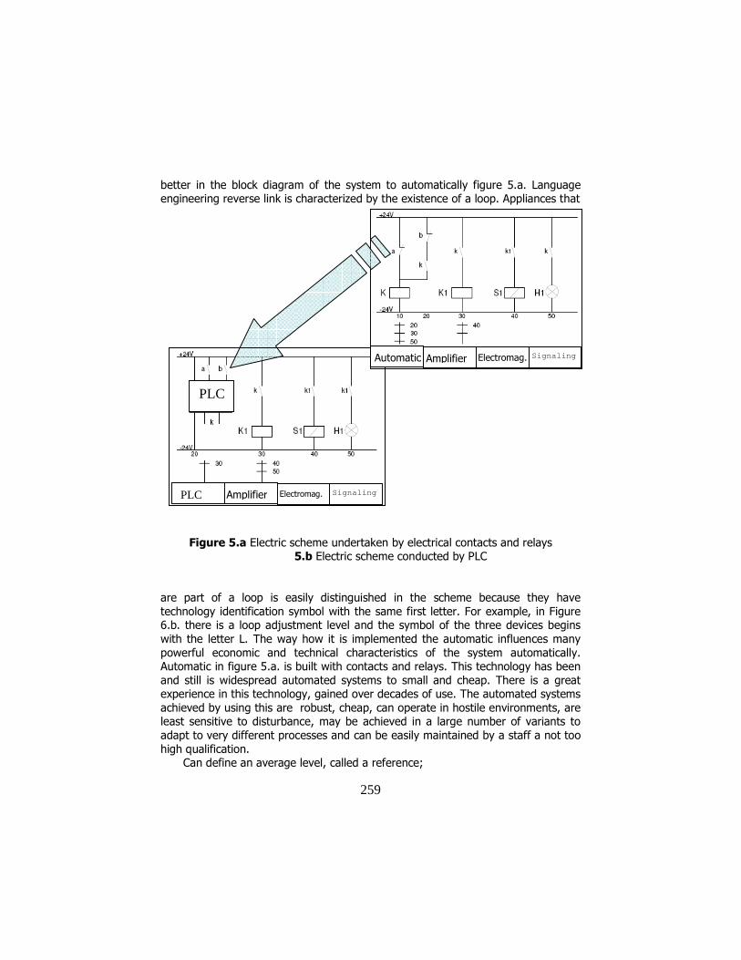
better in the block diagram of the system to automatically figure 5.a. Language engineering reverse link is characterized by the existence of a loop. Appliances that
Figure 5.a Electric scheme undertaken by electrical contacts and relays 5.b Electric scheme conducted by PLC
are part of a loop is easily distinguished in the scheme because they have technology identification symbol with the same first letter. For example, in Figure 6.b. there is a loop adjustment level and the symbol of the three devices begins with the letter L. The way how it is implemented the automatic influences many powerful economic and technical characteristics of the system automatically. Automatic in figure 5.a. is built with contacts and relays. This technology has been and still is widespread automated systems to small and cheap. There is a great experience in this technology, gained over decades of use. The automated systems achieved by using this are robust, cheap, can operate in hostile environments, are least sensitive to disturbance, may be achieved in a large number of variants to adapt to very different processes and can be easily maintained by a staff a not too high qualification.
Can define an average level, called a reference;
PLC Amplifier Electromag. Signaling
Automatic Amplifier Electromag. Signaling
PLC

260
2
min+= Maxw
(1) and maximum error
2
min−= Maxem
(2) it’s maximum percentage error
min
min
+−=
Max
Max
w
em
(3)
Another performance of the system automatically T0 is the period of filling and emptying the tank. Obviously, the error is less with both the level there is more constant and closer to the reference w, but maneuvers filling-emptying are repeated, ie, T0 is small. In many cases the error is chosen is such that T0> 10 minutes. In addition to maintaining a constant level in the reservoir, Automated signals the operator and the emergence of various desired and undesired events in the operation. In this simple example is the signaling of filling the tank through the H1 lamp circuit 50 of the scheme of figure 5.a. Finally, it notes that the systems and automatically relay contacts in figure 5.a. operator is still present. Its role has been reduced but only to fix the reference levels Max. and min. Unfortunately changing the reference electrode assembly consists in a mounting of the electrodes of the transducer on the reservoir at different distances, and thus of the driving distance is not entirely possible. This is a major shortcoming of the plant using a level to adjust automatically and relay contacts. Automatic and relay contacts in Figure 5.a. can be replaced easily without the operation and performance to change with PLC - Programmable Logic Controller, figure 5.b. In the new technological scheme of automation equipment in figure 6.b, Programmable Logic Controller is represented as a diamond. The change appears minor in reality block with number 2 no longer includes a relay and a few contacts as in figure 6.a, but a true microcomputer spe-cialized for dealing with logical variables. Unlike the PC-type computers, automated programs are designed and constructed to operate safe in a hostile environment, full of disturbances. In this case, Programmable Logic Controller is relatively ex-pensive. It is cost effective to replace with PLC, with an automatic relay contacts and only if it contains more than 30 relays. Algorithm with an PLC system is pre-sented as a program. Programmable Logic Controller design consists in this case, to a great extent in developing the program for Programmable Logic Controller This design may be assisted by computer program automatically develops the scheme carried out based on equivalent electrical contacts and relays. In our case should be introduced, possibly in the form of graphics, layout consists of circuits 10 and 20 in figure 5.b.

261
Figure 6.a. Technological scheme of the system automatically contacts and relays 6.b. Technological scheme of the system automatically PLC
An important technical feature new automated system, determining the dis-tance value desired level, called the reference may be obtained by using a regula-tor with two positions [6].
Technological scheme of the plant arises with two positions regulator is shown in figure 6.b. Transducer Level 1 consists of a primary measuring the level trans-mitter and a remote that value. Usually the transmission distance is under a unified signal of the current value of between 4 and 20 mA. The number 2 is the regulator with two positions. It provides the same performance due to relations (1), (2) and (3), but the technology for implementation of the algorithm is different from the two positions regulator. Regulator is usually an electronic device. The signal regu-lator for entry into a unified signal power and signal output is a contact k acting relay switch K1 of electromagnetic S1 in figure 6.b. Block scheme of a system automatically two positions regulator is show in figure 1. It consists of a filter - converter, a comparator, drawn as a circle and a compensa-
a
b

262
tor of error. Filter - the converter of the two positions regulator, converts the signal entered by the operator, the reference r in an rf signal that can be compared with the size of reaction yr. Comparator block of regulator made rf signal decrease of the size and responsiveness yr and provides output error e.
rf yre −= (4)
Rf signals yr and must have the same size to be low in relation (4). They are, for example, voltage signals merged with value between 0 and 10 volts. Reference signal r is entered by the operator, such as angle of rotation of a potentiometer and has another unit of measure than yr. Provide compensation to output a com-mand signal in the form of contact so that u bring to error is to vanish. Input-output relationship of a compensatory curve type hysteresis with the cycle of figure 7 as:
2
min−= Maxh
(5) Comparing this relationship to relationship (2) that result in the automatic regula-tor with two positions maximum error is:
he =max (6)
An essential feature of any automated system is an inverse relationship to
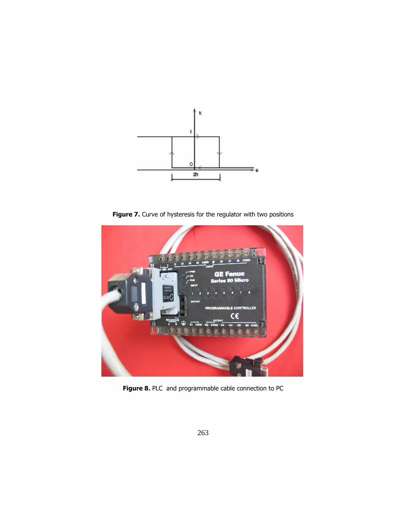
negative output regulator of the entry. The word suggests that the negative signal yr who travel this way precludes reference rf. This is underlined by a minus sign indicating the entrance of the comparator in figure 1. The algorithm of working of the with two positions regulator is represented in figure 8, but is less intuitive be-cause it refers to the error e and not to the level y. If the error is larger and nega-tive, then the size of the order of regulator in the form of contact k takes the value 1, the valve V1 is opened and the tank is filled. If the error is large and positive when k = 0, valve V1 closes and the tank is empty. For small errors, with the value placed inside hysteresis cycle of figure 7, the output k of the compensator retains previous value. This is indicated by arrows on the curve hysteresis. Figure 8 presents a model of Programmable Logic Controller product GE Fanuc company, Micro 90 a model that was used for the experimental installation. The connection of the programmer Programmable Logic Controller (PC or hand-held programmer) is via serial interface RS 485 and a converter RS 485-RS 232 [7].
263
Figure 7. Curve of hysteresis for the regulator with two positions
Figure 8. PLC and programmable cable connection to PC

264
Figure 9. The experimental installation for automatic filling of a reservoir
4. Conclusion
From their appearance, Programmable Logic Controller have spread rapidly in the industry and today is one of the most widely equipment. Programmable Logic Controller success is due primarily low price and that can be fang and eventually scheduled staff with high level training in computer science. Programmable Logic Controller are simple microcomputers, specially built to deal with program issues sequential logic and replace the command automation of sequential logic circuits implemented with wired logic or relays. Such equipment provides generally fewer opportunities than computers or information processing, but can be easily used by personnel less experienced in computer science, programming languages because of easier, such as relays with language, language or Boolean equations graphical languages. Conduct a program on a Programmable Logic Controller is generally synchronous type, which eliminates complications that arise when multitasking. Knowledge of hardware structure and especially the way of achieving and imple-menting a program on a Programmable Logic Controller, the basics of structured programming, are important things for an engineer in the electric field, and more. Through this article, the authors propose their direct engagement in the effort to train staff of engineers participating in the effort to re industry in our country, that effort is, in our view, the main objective of Romania in the coming years.

265
References
[1] Ruja I. Tehnica reglarii automate, Editura Eftimie Murgu, Resita 1998. [2] Ruja I. Actionari electrice si automatizari - aplicatii, Editura Eftimie Murgu, Resita 1997. [3] Larionescu S. ,Teoria Sistemelor, Editura Matrixrom, Bucuresti, 2006. [4] Mărgineanu I., Automate programabile, Editura Albastră, Cluj Napoca, 2005. [5] *** Users manual GE FANUC AUTOMATION GFK-1065F-1998. [6] Dorf R., Bishop R., Modern Control Systems, Addison-Wesley, New York, 1998. [7] Dutton K., Thompson S., Barraclough., The art of control engineering, Addison-Wesley, New York, 1997.
Addresses:
• Drd. Eng. Marius Tufoi, “Eftimie Murgu” University of ReşiŃa, PiaŃa Traian Vuia, nr. 1-4, 320085, ReşiŃa, [email protected] • Drd. Eng. Viorel Bizău, “Eftimie Murgu” University of ReşiŃa, PiaŃa Traian Vuia, nr. 1-4, 320085, ReşiŃa, [email protected] • Conf. Dr. Eng. Constantin Marta, “Eftimie Murgu” University of ReşiŃa, PiaŃa Traian Vuia, nr. 1-4, 320085, ReşiŃa, [email protected]