Embed Size (px)
Citation preview
hp procurveswitch 4108gl
management andconfiguration guide
www.hp.com/go/hpprocurve


HP Procurve Switch 4108GL
Management and Configuration Guide
Software Release G.01.xx or Later
Hewlett-Packard Company8000 Foothills Boulevard, m/s 5551Roseville, California 95747-5551http://www.hp.com/go/hpprocurve
© Copyright 2001 Hewlett-Packard CompanyAll Rights Reserved.
This document contains information which is protected by copyright. Reproduction, adaptation, or translation without prior permission is prohibited, except as allowed under the copyright laws.
Publication Number
5969-2378May 2001
Applicable Product
HP Procurve Switch 4108GL (J4865A)
Trademark Credits
Microsoft, Windows, Windows 95, and Microsoft Windows NT are registered trademarks of Microsoft Corporation. Internet Explorer is a trademark of Microsoft Corporation.Ethernet is a registered trademark of Xerox Corporation.Netscape is a registered trademark of Netscape Corporation.
Disclaimer
The information contained in this document is subject to change without notice.
HEWLETT-PACKARD COMPANY MAKES NO WARRANTY OF ANY KIND WITH REGARD TO THIS MATERIAL, INCLUDING, BUT NOT LIMITED TO, THE IMPLIED WARRANTIES OF MERCHANTABILITY AND FITNESS FOR A PARTICULAR PURPOSE. Hewlett-Packard shall not be liable for errors contained herein or for incidental or consequential damages in connection with the furnishing, performance, or use of this material.
Hewlett-Packard assumes no responsibility for the use or reliability of its software on equipment that is not furnished by Hewlett-Packard.
Warranty
See the Customer Support/Warranty booklet included with the product.
A copy of the specific warranty terms applicable to your Hewlett-Packard products and replacement parts can be obtained from your HP Sales and Service Office or authorized dealer.
Preface
Preface
Use of This Guide and Other Procurve Switch Documentation
This guide describes how to use the command line interface (CLI), menu interface, and web browser interface for the HP Procurve Switch 4108GL—also referred to as the Switch 4108GL.
� If you need information on specific parameters in the menu interface, refer to the online help provided in the interface.
� If you need information on a specific command in the CLI, type the command name followed by “help” (<command> help).
� If you need information on specific features in the HP Web Browser Interface (hereafter referred to as the “web browser interface”), use the online help available for the web browser interface. For more information on web browser Help options, refer to “Online Help for the HP Web Browser Interface” on page 4-12.
� If you need further information on Hewlett-Packard switch technology, refer to HP’s Procurve website at:
http://www.hp.com/go/hpprocurve
Just Want a Quick Start?
IP Addressing. If you just want to give the switch an IP address so that it can communicate on your network, or if you are not using VLANs, HP recommends that you use the Switch Setup screen to quickly configure IP addressing. To do so, do one of the following:
� Enter setup at the CLI Manager level prompt.
HP4108# setup
� Select 8. Run Setup in the Main Menu of the menu interface.
For more on using the Switch Setup screen, see the Installation and Getting
Started Guide you received with the switch.
iii
Preface
To Set Up and Install the Switch in Your Network
Use the HP Procurve Switch 4108GL Installation and Getting Started Guide (shipped with the switch) to guide you in the following:
� Physically installing the switch in your network
� Quickly assigning an IP address and subnet mask, set a Manager pass-word, and (optionally) configure other basic features.
iv
Contents
Preface . . . . . . . . . . . . . . . . . . . . . . . . . . . . . . . . . . . . . . . . . . . . . . . . . . . . . . . . iii
Use of This Guide and Other Procurve Switch Documentation . . . . . . iii
Just Want a Quick Start? . . . . . . . . . . . . . . . . . . . . . . . . . . . . . . . . . . . . . . iii
To Set Up and Install the Switch in Your Network . . . . . . . . . . . . . . . . . iv
Selecting a Management Interface
Contents . . . . . . . . . . . . . . . . . . . . . . . . . . . . . . . . . . . . . . . . . . . . . . . . . . . . . . 1-1
Overview . . . . . . . . . . . . . . . . . . . . . . . . . . . . . . . . . . . . . . . . . . . . . . . . . . . . . 1-2
Understanding Management Interfaces . . . . . . . . . . . . . . . . . . . . . . . . . 1-2
Advantages of Using the Menu Interface . . . . . . . . . . . . . . . . . . . . . . . . 1-3
Advantages of Using the CLI . . . . . . . . . . . . . . . . . . . . . . . . . . . . . . . . . . . 1-4
Advantages of Using the HP Web Browser Interface . . . . . . . . . . . . . 1-5
Advantages of Using HP TopTools for Hubs & Switches . . . . . . . . . 1-6
Using the Menu Interface
Contents . . . . . . . . . . . . . . . . . . . . . . . . . . . . . . . . . . . . . . . . . . . . . . . . . . . . . . 2-1
Overview . . . . . . . . . . . . . . . . . . . . . . . . . . . . . . . . . . . . . . . . . . . . . . . . . . . . . 2-2
Starting and Ending a Menu Session . . . . . . . . . . . . . . . . . . . . . . . . . . . 2-3
How To Start a Menu Interface Session . . . . . . . . . . . . . . . . . . . . . . . . . 2-4
How To End a Menu Session and Exit from the Console: . . . . . . . . . . 2-5
Main Menu Features . . . . . . . . . . . . . . . . . . . . . . . . . . . . . . . . . . . . . . . . . . 2-7
Screen Structure and Navigation . . . . . . . . . . . . . . . . . . . . . . . . . . . . . . . 2-9
Rebooting the Switch . . . . . . . . . . . . . . . . . . . . . . . . . . . . . . . . . . . . . . . . . 2-12
Menu Features List . . . . . . . . . . . . . . . . . . . . . . . . . . . . . . . . . . . . . . . . . . . 2-14
Where To Go From Here . . . . . . . . . . . . . . . . . . . . . . . . . . . . . . . . . . . . . . 2-15
Using the Command Line Interface (CLI)
Chapter Contents . . . . . . . . . . . . . . . . . . . . . . . . . . . . . . . . . . . . . . . . . . . . . 3-1
v
Overview . . . . . . . . . . . . . . . . . . . . . . . . . . . . . . . . . . . . . . . . . . . . . . . . . . . . . 3-2
Accessing the CLI . . . . . . . . . . . . . . . . . . . . . . . . . . . . . . . . . . . . . . . . . . . . . 3-2
Using the CLI . . . . . . . . . . . . . . . . . . . . . . . . . . . . . . . . . . . . . . . . . . . . . . . . . 3-2
Privilege Levels at Logon . . . . . . . . . . . . . . . . . . . . . . . . . . . . . . . . . . . . . 3-3
Privilege Level Operation . . . . . . . . . . . . . . . . . . . . . . . . . . . . . . . . . . . . . 3-4
How To Move Between Levels . . . . . . . . . . . . . . . . . . . . . . . . . . . . . . . . 3-7
Listing Commands and Command Options . . . . . . . . . . . . . . . . . . . . . . 3-8
Displaying CLI "Help" . . . . . . . . . . . . . . . . . . . . . . . . . . . . . . . . . . . . . . . 3-11
Configuration Commands and the Context Configuration Modes . . 3-13
CLI Control and Editing . . . . . . . . . . . . . . . . . . . . . . . . . . . . . . . . . . . . . . 3-16
Using the HP Web Browser Interface
Chapter Contents . . . . . . . . . . . . . . . . . . . . . . . . . . . . . . . . . . . . . . . . . . . . . 4-1
Overview . . . . . . . . . . . . . . . . . . . . . . . . . . . . . . . . . . . . . . . . . . . . . . . . . . . . . 4-2
General Features . . . . . . . . . . . . . . . . . . . . . . . . . . . . . . . . . . . . . . . . . . . . . . 4-3
Web Browser Interface Requirements . . . . . . . . . . . . . . . . . . . . . . . . . . 4-4
Starting an HP Web Browser Interface Session with the Switch . . 4-5
Using a Standalone Web Browser in a PC or UNIX Workstation . . . . 4-5
Using HP TopTools for Hubs & Switches . . . . . . . . . . . . . . . . . . . . . . . 4-6
Tasks for Your First HP Web Browser Interface Session . . . . . . . . . 4-8
Viewing the “First Time Install” Window . . . . . . . . . . . . . . . . . . . . . . . . 4-8
Creating Usernames and Passwords in the Browser Interface . . . . . . 4-9
Online Help for the HP Web Browser Interface . . . . . . . . . . . . . . . . . 4-12
Support/Mgmt URLs Feature . . . . . . . . . . . . . . . . . . . . . . . . . . . . . . . . . . 4-13
Support URL . . . . . . . . . . . . . . . . . . . . . . . . . . . . . . . . . . . . . . . . . . . . . . 4-14
Help and the Management Server URL . . . . . . . . . . . . . . . . . . . . . . . . 4-14
Status Reporting Features . . . . . . . . . . . . . . . . . . . . . . . . . . . . . . . . . . . . 4-16
The Overview Window . . . . . . . . . . . . . . . . . . . . . . . . . . . . . . . . . . . . . . 4-16
The Port Utilization and Status Displays . . . . . . . . . . . . . . . . . . . . . . . 4-17
The Alert Log . . . . . . . . . . . . . . . . . . . . . . . . . . . . . . . . . . . . . . . . . . . . . . 4-20
The Status Bar . . . . . . . . . . . . . . . . . . . . . . . . . . . . . . . . . . . . . . . . . . . . . 4-23
Setting Fault Detection Policy . . . . . . . . . . . . . . . . . . . . . . . . . . . . . . . . 4-24
vi
Switch Memory and Configuration
Chapter Contents . . . . . . . . . . . . . . . . . . . . . . . . . . . . . . . . . . . . . . . . . . . . . 5-1
Overview . . . . . . . . . . . . . . . . . . . . . . . . . . . . . . . . . . . . . . . . . . . . . . . . . . . . . 5-2
Overview of Configuration File Management . . . . . . . . . . . . . . . . . . . 5-2
Using the CLI To Implement Configuration Changes . . . . . . . . . . . . 5-4
Using the Menu and Web Browser Interfaces To Implement
Configuration Changes . . . . . . . . . . . . . . . . . . . . . . . . . . . . . . . . . . . . . . . . 5-7
Using the Menu Interface To Implement Configuration Changes . . . 5-8
Using the Web Browser Interface To Implement Configuration Changes . . . . . . . . . . . . . . . . . . . . . . . . . . . . . . . . . . . . . . . . . . . . . . . . . . 5-11
Using Primary and Secondary Flash Image Options . . . . . . . . . . . . . 5-11
Displaying the Current Flash Image Data . . . . . . . . . . . . . . . . . . . . . . 5-12
OS Downloads . . . . . . . . . . . . . . . . . . . . . . . . . . . . . . . . . . . . . . . . . . . . . 5-14
Local OS Replacement and Removal . . . . . . . . . . . . . . . . . . . . . . . . . . 5-15
Rebooting the Switch . . . . . . . . . . . . . . . . . . . . . . . . . . . . . . . . . . . . . . . 5-17
Operating Notes . . . . . . . . . . . . . . . . . . . . . . . . . . . . . . . . . . . . . . . . . . . . 5-19
Interface Access and System Information
Chapter Contents . . . . . . . . . . . . . . . . . . . . . . . . . . . . . . . . . . . . . . . . . . . . . 6-1
Overview . . . . . . . . . . . . . . . . . . . . . . . . . . . . . . . . . . . . . . . . . . . . . . . . . . . . . 6-2
Interface Access: Console/Serial Link, Web, and Inbound Telnet . 6-3
Menu: Modifying the Interface Access . . . . . . . . . . . . . . . . . . . . . . . . . . 6-4
CLI: Modifying the Interface Access . . . . . . . . . . . . . . . . . . . . . . . . . . . . 6-5
System Information . . . . . . . . . . . . . . . . . . . . . . . . . . . . . . . . . . . . . . . . . . . 6-8
Menu: Viewing and Configuring System Information . . . . . . . . . . . . . . 6-9
CLI: Viewing and Configuring System Information . . . . . . . . . . . . . . 6-10
Web: Configuring System Parameters . . . . . . . . . . . . . . . . . . . . . . . . . 6-13
Configuring IP Addressing
Contents . . . . . . . . . . . . . . . . . . . . . . . . . . . . . . . . . . . . . . . . . . . . . . . . . . . . . . 7-1
Overview . . . . . . . . . . . . . . . . . . . . . . . . . . . . . . . . . . . . . . . . . . . . . . . . . . . . . 7-2
IP Configuration . . . . . . . . . . . . . . . . . . . . . . . . . . . . . . . . . . . . . . . . . . . . . . 7-3
Just Want a Quick Start? . . . . . . . . . . . . . . . . . . . . . . . . . . . . . . . . . . . . . 7-4
vii
IP Addressing with Multiple VLANs . . . . . . . . . . . . . . . . . . . . . . . . . . . . 7-4
IP Addressing in a Stacking Environment . . . . . . . . . . . . . . . . . . . . . . . 7-5
Menu: Configuring IP Address, Gateway, and Time-To-Live (TTL) . . 7-5
CLI: Configuring IP Address, Gateway, Time-To-Live (TTL), and Timep . . . . . . . . . . . . . . . . . . . . . . . . . . . . . . . . . . . . . . . . . . . . . . . . . . . . . 7-7
Web: Configuring IP Addressing . . . . . . . . . . . . . . . . . . . . . . . . . . . . . . . 7-9
How IP Addressing Affects Switch Operation . . . . . . . . . . . . . . . . . . . . 7-9
Globally Assigned IP Network Addresses . . . . . . . . . . . . . . . . . . . . . . 7-14
Time Protocols
Chapter Contents . . . . . . . . . . . . . . . . . . . . . . . . . . . . . . . . . . . . . . . . . . . . . 8-1
Overview . . . . . . . . . . . . . . . . . . . . . . . . . . . . . . . . . . . . . . . . . . . . . . . . . . . . . 8-2
TimeP Time Synchronization . . . . . . . . . . . . . . . . . . . . . . . . . . . . . . . . . . 8-2
SNTP Time Synchronization . . . . . . . . . . . . . . . . . . . . . . . . . . . . . . . . . . 8-2
Overview: Selecting a Time Synchronization Protocol or Turning Off
Time Protocol Operation . . . . . . . . . . . . . . . . . . . . . . . . . . . . . . . . . . . . . . 8-3
General Steps for Running a Time Protocol on the Switch: . . . . . . . . 8-3
Disabling Time Synchronization . . . . . . . . . . . . . . . . . . . . . . . . . . . . . . . 8-4
SNTP: Viewing, Selecting, and Configuring . . . . . . . . . . . . . . . . . . . . . 8-4
Menu: Viewing and Configuring SNTP . . . . . . . . . . . . . . . . . . . . . . . . . . 8-5
CLI: Viewing and Configuring SNTP . . . . . . . . . . . . . . . . . . . . . . . . . . . . 8-8
TimeP: Viewing, Selecting, and Configuring . . . . . . . . . . . . . . . . . . . . 8-13
Menu: Viewing and Configuring TimeP . . . . . . . . . . . . . . . . . . . . . . . . 8-14
CLI: Viewing and Configuring TimeP . . . . . . . . . . . . . . . . . . . . . . . . . . 8-16
SNTP Unicast Time Polling with Multiple SNTP Servers . . . . . . . . 8-20
Address Prioritization . . . . . . . . . . . . . . . . . . . . . . . . . . . . . . . . . . . . . . . 8-21
Adding and Deleting SNTP Server Addresses . . . . . . . . . . . . . . . . . . . 8-21
Menu Interface Operation with Multiple SNTP Server Addresses Configured 8-23
SNTP Messages in the Event Log . . . . . . . . . . . . . . . . . . . . . . . . . . . . . . 8-23
Using Passwords and TACACS+ To Protect Against
Unauthorized Access
Contents . . . . . . . . . . . . . . . . . . . . . . . . . . . . . . . . . . . . . . . . . . . . . . . . . . . . . . 9-1
viii
Overview . . . . . . . . . . . . . . . . . . . . . . . . . . . . . . . . . . . . . . . . . . . . . . . . . . . . . 9-2
Configuring Username and Password Security . . . . . . . . . . . . . . . . . . 9-3
Menu: Configuring Passwords . . . . . . . . . . . . . . . . . . . . . . . . . . . . . . . . . 9-5
CLI: Setting Manager and Operator Passwords . . . . . . . . . . . . . . . . . . . 9-6
Web: Configuring User-Names and Passwords . . . . . . . . . . . . . . . . . . . 9-7
TACACS+ Authentication for Central Control of Switch Access Security 9-8
Terminology Used in TACACS Applications: . . . . . . . . . . . . . . . . . . . . 9-9
General System Requirements . . . . . . . . . . . . . . . . . . . . . . . . . . . . . . . . 9-10
General Authentication Setup Procedure . . . . . . . . . . . . . . . . . . . . . . 9-11
Configuring TACACS+ on the Switch . . . . . . . . . . . . . . . . . . . . . . . . . . 9-14
How Authentication Operates . . . . . . . . . . . . . . . . . . . . . . . . . . . . . . . . 9-24
Using the Encryption Key . . . . . . . . . . . . . . . . . . . . . . . . . . . . . . . . . . . 9-26
Controlling Web Browser Interface Access When Using TACACS+ Authentication 9-28
Messages . . . . . . . . . . . . . . . . . . . . . . . . . . . . . . . . . . . . . . . . . . . . . . . . . . 9-28
Operating Notes . . . . . . . . . . . . . . . . . . . . . . . . . . . . . . . . . . . . . . . . . . . . 9-29
Troubleshooting TACACS+ Operation . . . . . . . . . . . . . . . . . . . . . . . . . 9-29
Using Authorized IP Managers for Increased Management
Security
Chapter Contents . . . . . . . . . . . . . . . . . . . . . . . . . . . . . . . . . . . . . . . . . . . . 10-1
Overview . . . . . . . . . . . . . . . . . . . . . . . . . . . . . . . . . . . . . . . . . . . . . . . . . . . . 10-2
Using Authorized IP Managers . . . . . . . . . . . . . . . . . . . . . . . . . . . . . . . 10-4
Access Levels . . . . . . . . . . . . . . . . . . . . . . . . . . . . . . . . . . . . . . . . . . . . . . 10-5
Defining Authorized Management Stations . . . . . . . . . . . . . . . . . . . . . 10-5
Menu: Viewing and Configuring IP Authorized Managers . . . . . . . . . 10-7
CLI: Viewing and Configuring Authorized IP Managers . . . . . . . . . . . 10-8
Web: Configuring IP Authorized Managers . . . . . . . . . . . . . . . . . . . . 10-10
Building IP Masks . . . . . . . . . . . . . . . . . . . . . . . . . . . . . . . . . . . . . . . . . 10-10
Operating and Troubleshooting Notes . . . . . . . . . . . . . . . . . . . . . . . . 10-13
Optimizing Port Usage Through Traffic Control and Port
Trunking
Chapter Contents . . . . . . . . . . . . . . . . . . . . . . . . . . . . . . . . . . . . . . . . . . . . 11-1
ix
Overview . . . . . . . . . . . . . . . . . . . . . . . . . . . . . . . . . . . . . . . . . . . . . . . . . . . . 11-2
Viewing Port Status and Configuring Port Parameters . . . . . . . . . . 11-2
Menu: Viewing Port Status and Configuring Port Parameters . . . . . 11-5
CLI: Viewing Port Status and Configuring Port Parameters . . . . . . . 11-6
Web: Viewing Port Status and Configuring Port Parameters . . . . . . 11-9
Port Trunking . . . . . . . . . . . . . . . . . . . . . . . . . . . . . . . . . . . . . . . . . . . . . . . 11-10
Switch 4108GL Port Trunk Features and Operation . . . . . . . . . . . . . 11-11
Trunk Configuration Methods . . . . . . . . . . . . . . . . . . . . . . . . . . . . . . . 11-12
Menu: Viewing and Configuring a Static Trunk Group . . . . . . . . . . . 11-16
CLI: Viewing and Configuring a Static or Dynamic Port Trunk Group . . 11-18
Web: Viewing Existing Port Trunk Groups . . . . . . . . . . . . . . . . . . . . 11-24
Trunk Group Operation Using LACP . . . . . . . . . . . . . . . . . . . . . . . . . 11-25
Trunk Group Operation Using the “Trunk” Option . . . . . . . . . . . . . . 11-28
Trunk Operation Using the “FEC” Option . . . . . . . . . . . . . . . . . . . . . 11-29
How the Switch Lists Trunk Data . . . . . . . . . . . . . . . . . . . . . . . . . . . . 11-29
Outbound Traffic Distribution Across Trunked Links . . . . . . . . . . . 11-30
Configuring for Network Management Applications
Chapter Contents . . . . . . . . . . . . . . . . . . . . . . . . . . . . . . . . . . . . . . . . . . . . 12-1
Overview . . . . . . . . . . . . . . . . . . . . . . . . . . . . . . . . . . . . . . . . . . . . . . . . . . . . 12-2
SNMP Management Features . . . . . . . . . . . . . . . . . . . . . . . . . . . . . . . . . 12-2
Configuring for SNMP Access to the Switch . . . . . . . . . . . . . . . . . . . . 12-4
SNMP Communities . . . . . . . . . . . . . . . . . . . . . . . . . . . . . . . . . . . . . . . . 12-5
Trap Receivers and Authentication Traps . . . . . . . . . . . . . . . . . . . . . 12-8
Advanced Management: RMON . . . . . . . . . . . . . . . . . . . . . . . . . . . . . . 12-11
CDP . . . . . . . . . . . . . . . . . . . . . . . . . . . . . . . . . . . . . . . . . . . . . . . . . . . . . . . . 12-12
Introduction . . . . . . . . . . . . . . . . . . . . . . . . . . . . . . . . . . . . . . . . . . . . . . 12-12
Outgoing Packets . . . . . . . . . . . . . . . . . . . . . . . . . . . . . . . . . . . . . . . . . 12-14
Incoming CDP Packets . . . . . . . . . . . . . . . . . . . . . . . . . . . . . . . . . . . . . 12-15
Configuring CDP on the Switch . . . . . . . . . . . . . . . . . . . . . . . . . . . . . . 12-18
Viewing the Switch’s Current CDP Configuration . . . . . . . . . . . . . . 12-19
Viewing the Current Contents of the Switch’s CDP Neighbors Table . . . . . . . . . . . . . . . . . . . . . . . . . . . . . . . . . . . . . . . . . . . . . . . . . . . . 12-19
Clearing (Resetting) the CDP Neighbors Table . . . . . . . . . . . . . . . . . 12-20
x
Configuring CDP Operation . . . . . . . . . . . . . . . . . . . . . . . . . . . . . . . . . 12-21
Effect of Spanning Tree (STP) On CDP Packet Transmission . . . . 12-23
How the Switch Selects the IP Address To Include in Outbound CDP Packets 12-24
CDP Neighbor Data and MIB Objects . . . . . . . . . . . . . . . . . . . . . . . . . 12-25
Operating Notes . . . . . . . . . . . . . . . . . . . . . . . . . . . . . . . . . . . . . . . . . . . 12-27
HP Procurve Stack Management
Chapter Contents . . . . . . . . . . . . . . . . . . . . . . . . . . . . . . . . . . . . . . . . . . . . 13-1
Overview . . . . . . . . . . . . . . . . . . . . . . . . . . . . . . . . . . . . . . . . . . . . . . . . . . . . 13-3
HP Procurve Stack Management . . . . . . . . . . . . . . . . . . . . . . . . . . . . . . 13-4
Which Devices Support Stacking? . . . . . . . . . . . . . . . . . . . . . . . . . . . . 13-5
Components of HP Procurve Stack Management . . . . . . . . . . . . . . . . 13-6
General Stacking Operation . . . . . . . . . . . . . . . . . . . . . . . . . . . . . . . . . . 13-6
Operating Rules for Stacking . . . . . . . . . . . . . . . . . . . . . . . . . . . . . . . . . 13-7
Overview of Configuring and Bringing Up a Stack . . . . . . . . . . . . . . 13-10
Using the Menu Interface To View Stack Status and Configure Stacking 13-14
Using the Commander To Manage The Stack . . . . . . . . . . . . . . . . . . 13-18
Monitoring Stack Status . . . . . . . . . . . . . . . . . . . . . . . . . . . . . . . . . . . . 13-27
Using the CLI To View Stack Status and Configure Stacking . . . . . 13-31
SNMP Community Operation in a Stack . . . . . . . . . . . . . . . . . . . . . . 13-45
Using the CLI To Disable or Re-Enable Stacking . . . . . . . . . . . . . . . 13-46
Transmission Interval . . . . . . . . . . . . . . . . . . . . . . . . . . . . . . . . . . . . . . 13-46
Stacking Operation with Multiple VLANs Configured . . . . . . . . . . . 13-46
Web: Viewing and Configuring Stacking . . . . . . . . . . . . . . . . . . . . . . 13-47
Status Messages . . . . . . . . . . . . . . . . . . . . . . . . . . . . . . . . . . . . . . . . . . . 13-48
Port-Based Virtual LANs (VLANs) and GVRP
Chapter Contents . . . . . . . . . . . . . . . . . . . . . . . . . . . . . . . . . . . . . . . . . . . . 14-1
Overview . . . . . . . . . . . . . . . . . . . . . . . . . . . . . . . . . . . . . . . . . . . . . . . . . . . . 14-3
Port-Based Virtual LANs (Static VLANs) . . . . . . . . . . . . . . . . . . . . . . 14-4
Overview of Using VLANs . . . . . . . . . . . . . . . . . . . . . . . . . . . . . . . . . . . 14-7
Menu: Configuring VLAN Parameters . . . . . . . . . . . . . . . . . . . . . . . . . 14-11
CLI: Configuring VLAN Parameters . . . . . . . . . . . . . . . . . . . . . . . . . . 14-16
xi
Web: Viewing and Configuring VLAN Parameters . . . . . . . . . . . . . . 14-22
VLAN Tagging Information . . . . . . . . . . . . . . . . . . . . . . . . . . . . . . . . . 14-23
Effect of VLANs on Other Switch Features . . . . . . . . . . . . . . . . . . . . 14-27
VLAN Restrictions . . . . . . . . . . . . . . . . . . . . . . . . . . . . . . . . . . . . . . . . . 14-29
GVRP . . . . . . . . . . . . . . . . . . . . . . . . . . . . . . . . . . . . . . . . . . . . . . . . . . . . . . . 14-30
General Operation . . . . . . . . . . . . . . . . . . . . . . . . . . . . . . . . . . . . . . . . . 14-31
Per-Port Options for Handling GVRP “Unknown VLANs” . . . . . . . . 14-33
Per-Port Options for Dynamic VLAN Advertising and Joining . . . . 14-35
GVRP and VLAN Access Control . . . . . . . . . . . . . . . . . . . . . . . . . . . . . 14-36
Planning for GVRP Operation . . . . . . . . . . . . . . . . . . . . . . . . . . . . . . . 14-37
Configuring GVRP On a Switch . . . . . . . . . . . . . . . . . . . . . . . . . . . . . . 14-37
GVRP Operating Notes . . . . . . . . . . . . . . . . . . . . . . . . . . . . . . . . . . . . . 14-42
Multimedia Traffic Control with IP Multicast (IGMP)
Chapter Contents . . . . . . . . . . . . . . . . . . . . . . . . . . . . . . . . . . . . . . . . . . . . 15-1
Overview . . . . . . . . . . . . . . . . . . . . . . . . . . . . . . . . . . . . . . . . . . . . . . . . . . . . 15-2
General Operation and Features . . . . . . . . . . . . . . . . . . . . . . . . . . . . . . 15-3
IGMP Terms . . . . . . . . . . . . . . . . . . . . . . . . . . . . . . . . . . . . . . . . . . . . . . . 15-4
IGMP Operating Features . . . . . . . . . . . . . . . . . . . . . . . . . . . . . . . . . . . . 15-5
CLI: Configuring and Displaying IGMP . . . . . . . . . . . . . . . . . . . . . . . . 15-6
Web: Enabling or Disabling IGMP . . . . . . . . . . . . . . . . . . . . . . . . . . . . 15-10
How IGMP Operates . . . . . . . . . . . . . . . . . . . . . . . . . . . . . . . . . . . . . . . . . 15-11
Operation With or Without IP Addressing . . . . . . . . . . . . . . . . . . . . . 15-12
Automatic Fast-Leave IGMP . . . . . . . . . . . . . . . . . . . . . . . . . . . . . . . . 15-13
Forced Fast-Leave IGMP . . . . . . . . . . . . . . . . . . . . . . . . . . . . . . . . . . . 15-14
Configuring Per-Port Forced Fast-Leave IGMP . . . . . . . . . . . . . . . . . 15-17
Querier Operation . . . . . . . . . . . . . . . . . . . . . . . . . . . . . . . . . . . . . . . . . 15-18
The Switch Excludes Well-Known or Reserved Multicast Addresses
from IP Multicast Filtering . . . . . . . . . . . . . . . . . . . . . . . . . . . . . . . . . . 15-19
Spanning Tree Protocol (STP)
Chapter Contents . . . . . . . . . . . . . . . . . . . . . . . . . . . . . . . . . . . . . . . . . . . . 16-1
Overview . . . . . . . . . . . . . . . . . . . . . . . . . . . . . . . . . . . . . . . . . . . . . . . . . . . . 16-2
Menu: Configuring STP . . . . . . . . . . . . . . . . . . . . . . . . . . . . . . . . . . . . . . . 16-4
xii
CLI: Configuring STP . . . . . . . . . . . . . . . . . . . . . . . . . . . . . . . . . . . . . . . . . 16-5
Web: Enabling or Disabling STP . . . . . . . . . . . . . . . . . . . . . . . . . . . . . . . 16-9
How STP Operates . . . . . . . . . . . . . . . . . . . . . . . . . . . . . . . . . . . . . . . . . . . 16-9
STP Fast Mode . . . . . . . . . . . . . . . . . . . . . . . . . . . . . . . . . . . . . . . . . . . . 16-10
STP Operation with 802.1Q VLANs . . . . . . . . . . . . . . . . . . . . . . . . . . . 16-12
Monitoring and Analyzing Switch Operation
Chapter Contents . . . . . . . . . . . . . . . . . . . . . . . . . . . . . . . . . . . . . . . . . . . . 17-1
Overview . . . . . . . . . . . . . . . . . . . . . . . . . . . . . . . . . . . . . . . . . . . . . . . . . . . . 17-2
Status and Counters Data . . . . . . . . . . . . . . . . . . . . . . . . . . . . . . . . . . . . 17-3
Menu Access To Status and Counters . . . . . . . . . . . . . . . . . . . . . . . . . 17-4
General System Information . . . . . . . . . . . . . . . . . . . . . . . . . . . . . . . . . 17-5
Switch Management Address Information . . . . . . . . . . . . . . . . . . . . . . 17-6
Module Information . . . . . . . . . . . . . . . . . . . . . . . . . . . . . . . . . . . . . . . . 17-7
Port Status . . . . . . . . . . . . . . . . . . . . . . . . . . . . . . . . . . . . . . . . . . . . . . . . 17-8
Viewing Port and Trunk Group Statistics and Flow Control Status . 17-9
Viewing the Switch’s MAC Address Tables . . . . . . . . . . . . . . . . . . . . 17-12
Spanning Tree Protocol (STP) Information . . . . . . . . . . . . . . . . . . . . 17-17
Internet Group Management Protocol (IGMP) Status . . . . . . . . . . . 17-19
VLAN Information . . . . . . . . . . . . . . . . . . . . . . . . . . . . . . . . . . . . . . . . . 17-20
Web Browser Interface Status Information . . . . . . . . . . . . . . . . . . . . 17-22
Port Monitoring Features . . . . . . . . . . . . . . . . . . . . . . . . . . . . . . . . . . . 17-23
Menu: Configuring Port Monitoring . . . . . . . . . . . . . . . . . . . . . . . . . . 17-24
CLI: Configuring Port Monitoring . . . . . . . . . . . . . . . . . . . . . . . . . . . . 17-25
Web: Configuring Port Monitoring . . . . . . . . . . . . . . . . . . . . . . . . . . . 17-27
Troubleshooting
Chapter Contents . . . . . . . . . . . . . . . . . . . . . . . . . . . . . . . . . . . . . . . . . . . . 18-1
Overview . . . . . . . . . . . . . . . . . . . . . . . . . . . . . . . . . . . . . . . . . . . . . . . . . . . . 18-2
Troubleshooting Approaches . . . . . . . . . . . . . . . . . . . . . . . . . . . . . . . . . . 18-3
Browser or Telnet Access Problems . . . . . . . . . . . . . . . . . . . . . . . . . . . 18-4
Unusual Network Activity . . . . . . . . . . . . . . . . . . . . . . . . . . . . . . . . . . . . 18-6
Using the Event Log To Identify Problem Sources . . . . . . . . . . . . . 18-16
xiii
Menu: Entering and Navigating in the Event Log . . . . . . . . . . . . . . . 18-17
CLI: . . . . . . . . . . . . . . . . . . . . . . . . . . . . . . . . . . . . . . . . . . . . . . . . . . . . . 18-18
Diagnostic Tools . . . . . . . . . . . . . . . . . . . . . . . . . . . . . . . . . . . . . . . . . . . . 18-19
Port Auto-Negotiation . . . . . . . . . . . . . . . . . . . . . . . . . . . . . . . . . . . . . . 18-19
Ping and Link Tests . . . . . . . . . . . . . . . . . . . . . . . . . . . . . . . . . . . . . . . . 18-19
Displaying the Configuration File . . . . . . . . . . . . . . . . . . . . . . . . . . . . 18-24
CLI Administrative and Troubleshooting Commands . . . . . . . . . . . 18-25
Restoring the Factory-Default Configuration . . . . . . . . . . . . . . . . . 18-26
Restoring a Flash Image . . . . . . . . . . . . . . . . . . . . . . . . . . . . . . . . . . . . . 18-27
File Transfers
Appendix Contents . . . . . . . . . . . . . . . . . . . . . . . . . . . . . . . . . . . . . . . . . . . A-1
Overview . . . . . . . . . . . . . . . . . . . . . . . . . . . . . . . . . . . . . . . . . . . . . . . . . . . . A-2
Downloading an Operating System (OS) . . . . . . . . . . . . . . . . . . . . . . . A-2
General OS Download Rules . . . . . . . . . . . . . . . . . . . . . . . . . . . . . . . . . A-2
Using TFTP To Download an OS Image from a Server . . . . . . . . . . . A-3
Using Xmodem to Download an OS Image From a PC or UNIX Workstation A-6
Switch-to-Switch Download . . . . . . . . . . . . . . . . . . . . . . . . . . . . . . . . . A-9
Using the HP TopTools for Hubs & Switches Utility . . . . . . . . . . . . A-11
Troubleshooting TFTP Downloads . . . . . . . . . . . . . . . . . . . . . . . . . . . A-12
Transferring Switch Configurations . . . . . . . . . . . . . . . . . . . . . . . . . . A-13
Copying Diagnostic Data to a Remote Host, PC, or Unix Workstation A-16
MAC Address Management
Contents . . . . . . . . . . . . . . . . . . . . . . . . . . . . . . . . . . . . . . . . . . . . . . . . . . . . . B-1
Overview . . . . . . . . . . . . . . . . . . . . . . . . . . . . . . . . . . . . . . . . . . . . . . . . . . . . B-1
Determining MAC Addresses . . . . . . . . . . . . . . . . . . . . . . . . . . . . . . . . . . B-2
Menu: Viewing the Switch’s MAC Addresses . . . . . . . . . . . . . . . . . . . . B-3
CLI: Viewing the Port and VLAN MAC Addresses . . . . . . . . . . . . . . . . B-4
Daylight Savings Time on HP Procurve Switches
xiv
Selecting a Managem
ent Interface
1
Selecting a Management Interface
Contents
Overview . . . . . . . . . . . . . . . . . . . . . . . . . . . . . . . . . . . . . . . . . . . . . . . . . . . . . . 1-2
Understanding Management Interfaces . . . . . . . . . . . . . . . . . . . . . . . . . . . . . 1-2
Advantages of Using the Menu Interface . . . . . . . . . . . . . . . . . . . . . . . . . . . . 1-3
Advantages of Using the CLI . . . . . . . . . . . . . . . . . . . . . . . . . . . . . . . . . . . . . . 1-4
Advantages of Using the HP Web Browser Interface . . . . . . . . . . . . . . . . . 1-5
Advantages of Using HP TopTools for Hubs & Switches . . . . . . . . . . . . . . 1-6
1-1
Selecting a Management InterfaceOverview
Sele
ctin
g a
Man
agem
ent
Inte
rfac
e
Overview
This chapter describes the following:
� Management interfaces for the Switch 4108GL
� Advantages of using each interface
Understanding Management Interfaces
Management interfaces enable you to reconfigure the switch and to monitor switch status and performance. The HP Switch 4108GL offers the following interfaces:
� Menu interface—a menu-driven interface offering a subset of switch commands through the built-in VT-100/ANSI console—page 1-3
� CLI—a command line interface offering the full set of switch commands through the VT-100/ANSI console built into the switch—page 1-4
� Web browser interface --a switch interface offering status information and a subset of switch commands through a standard web browser (such as Netscape Navigator or Microsoft Internet Explorer)—page 1-5
� HP TopTools for Hubs & Switches--an easy-to-use, browser-based network management tool that works with HP proactive networking features built into managed HP hubs and switches
This manual describes how to use the menu interface (chapter 2), the CLI (chapter 3), the web browser interface (chapter 4), and how to use these interfaces to configure and monitor the switch.
For information on how to access the web browser interface Help, see “Online Help for the Web Browser Interface” on page 4-12.
To use HP TopTools for Hubs & Switches, refer to the HP TopTools User’s
Guide and the TopTools online help, which are available electronically with the TopTools software. (To get a copy of HP TopTools for Hubs & Switches software, see the Read Me First document shipped with your switch.)
1-2
Selecting a Management InterfaceAdvantages of Using the Menu Interface
Selecting a Managem
ent Interface
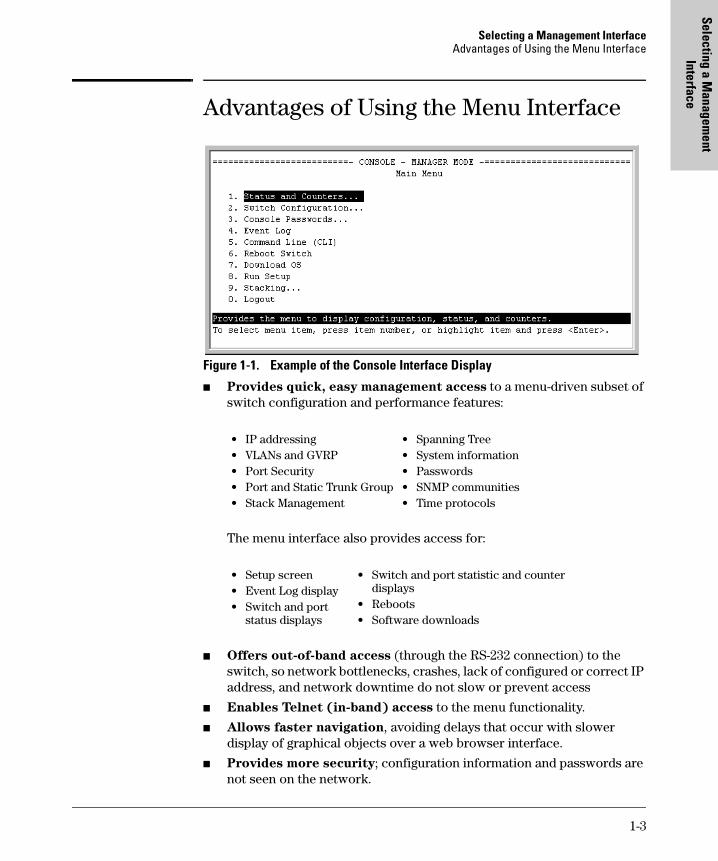
Advantages of Using the Menu InterfaceFigure 1-1. Example of the Console Interface Display
� Provides quick, easy management access to a menu-driven subset of switch configuration and performance features:
The menu interface also provides access for:
� Offers out-of-band access (through the RS-232 connection) to the switch, so network bottlenecks, crashes, lack of configured or correct IP address, and network downtime do not slow or prevent access
� Enables Telnet (in-band) access to the menu functionality.
� Allows faster navigation, avoiding delays that occur with slower display of graphical objects over a web browser interface.
� Provides more security; configuration information and passwords are not seen on the network.
• IP addressing• VLANs and GVRP• Port Security• Port and Static Trunk Group• Stack Management
• Spanning Tree• System information• Passwords • SNMP communities• Time protocols
• Setup screen• Event Log display• Switch and port
status displays
• Switch and port statistic and counter displays
• Reboots• Software downloads
1-3
Selecting a Management InterfaceAdvantages of Using the CLI
Sele
ctin
g a
Man
agem
ent
Inte
rfac
e
Advantages of Using the CLI
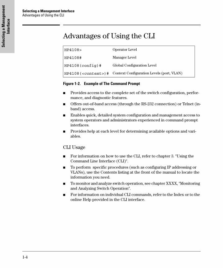
Figure 1-2. Example of The Command Prompt
� Provides access to the complete set of the switch configuration, perfor-mance, and diagnostic features.
� Offers out-of-band access (through the RS-232 connection) or Telnet (in-band) access.
� Enables quick, detailed system configuration and management access to system operators and administrators experienced in command prompt interfaces.
� Provides help at each level for determining available options and vari-ables.
CLI Usage
� For information on how to use the CLI, refer to chapter 3. "Using the Command Line Interface (CLI)".
� To perform specific procedures (such as configuring IP addressing or VLANs), use the Contents listing at the front of the manual to locate the information you need.
� To monitor and analyze switch operation, see chapter XXXX, "Monitoring and Analyzing Switch Operation".
� For information on individual CLI commands, refer to the Index or to the online Help provided in the CLI interface.
HP4108> Operator Level
HP4108# Manager Level
HP4108(config)# Global Configuration Level
HP4108(<context>)# Context Configuration Levels (port, VLAN)
1-4
Selecting a Management InterfaceAdvantages of Using the HP Web Browser Interface
Selecting a Managem
ent Interface
Advantages of Using the HP Web Browser Interface
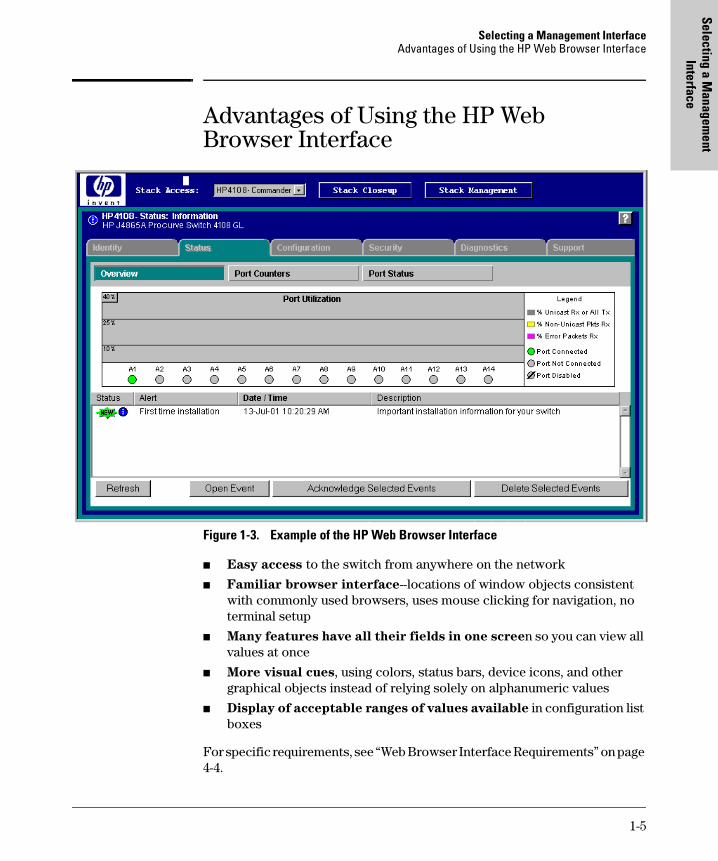
Figure 1-3. Example of the HP Web Browser Interface
� Easy access to the switch from anywhere on the network
� Familiar browser interface--locations of window objects consistent with commonly used browsers, uses mouse clicking for navigation, no terminal setup
� Many features have all their fields in one screen so you can view all values at once
� More visual cues, using colors, status bars, device icons, and other graphical objects instead of relying solely on alphanumeric values
� Display of acceptable ranges of values available in configuration list boxes
For specific requirements, see “Web Browser Interface Requirements” on page 4-4.
1-5
Selecting a Management InterfaceAdvantages of Using HP TopTools for Hubs & Switches
Sele
ctin
g a
Man
agem
ent
Inte
rfac
e
Advantages of Using HP TopTools for Hubs & Switches
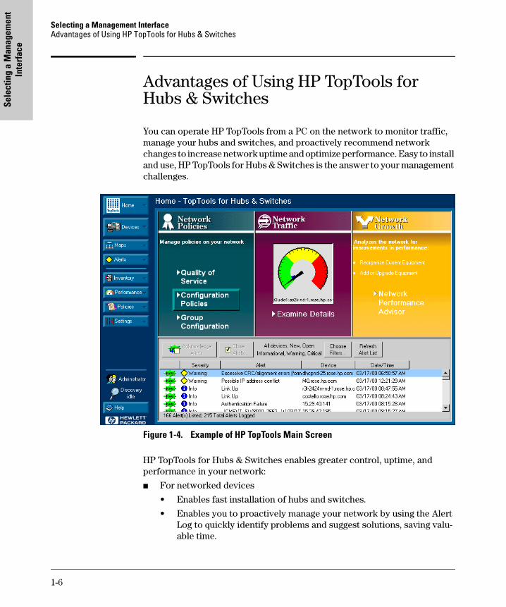
You can operate HP TopTools from a PC on the network to monitor traffic, manage your hubs and switches, and proactively recommend network changes to increase network uptime and optimize performance. Easy to install and use, HP TopTools for Hubs & Switches is the answer to your management challenges.
Figure 1-4. Example of HP TopTools Main Screen
HP TopTools for Hubs & Switches enables greater control, uptime, and performance in your network:
� For networked devices
• Enables fast installation of hubs and switches.
• Enables you to proactively manage your network by using the Alert Log to quickly identify problems and suggest solutions, saving valu-able time.
1-6
Selecting a Management InterfaceAdvantages of Using HP TopTools for Hubs & Switches
Selecting a Managem
ent Interface
• Notifies you when HP hubs use “self-healing” features to fix or limit common network problems.
• Provides a list of discovered devices, with device type, connectivity status, the number of new or open alerts for each device, and the type of management for each device.
• Provides graphical maps of your networked devices, from which you can access specific devices.
• Identifies users by port and lets you assign easy-to-remember names to any network device.
• Enables you to configure and monitor HP networked devices from your network management PC, including identity and status informa-tion, port counters, port on/off capability, sensitivity thresholds for traps, IP and security configuration, device configuration report, and other device features.
• Enables policy-based management through the Quality of Service feature (QoS) to establish traffic priority policies for controlling and improving throughput across all the HP switches in your network that support this feature.
� For network traffic:
• Watches the network for problems and displays real-time information about network status.
• Shows traffic and “top talker” nodes on screen.
• Uses traffic monitor diagrams to make bottlenecks easy to see.
• Improves network reliability through real-time fault isolation.
• Lets you see your entire network without having to put RMON probes on every segment (up to 1500 segments).
� For network growth:
• Monitors, stores, and analyzes network traffic to determine where upgrades are needed.
• Uses Network Performance Advisor for automatic traffic analysis and easy-to-understand reports that give clear, easy-to-follow plans for cost-effectivly upgrading your network.
1-7

Selecting a Management InterfaceAdvantages of Using HP TopTools for Hubs & Switches
Sele
ctin
g a
Man
agem
ent
Inte
rfac
e
1-8
Using the M
enu Interface
2
Using the Menu Interface
Contents
Overview . . . . . . . . . . . . . . . . . . . . . . . . . . . . . . . . . . . . . . . . . . . . . . . . . . . . . . 2-2
Starting and Ending a Menu Session . . . . . . . . . . . . . . . . . . . . . . . . . . . . . . . 2-3
How To Start a Menu Interface Session . . . . . . . . . . . . . . . . . . . . . . . . . 2-4
How To End a Menu Session and Exit from the Console: . . . . . . . . . . 2-5
Main Menu Features . . . . . . . . . . . . . . . . . . . . . . . . . . . . . . . . . . . . . . . . . . . . 2-7
Screen Structure and Navigation . . . . . . . . . . . . . . . . . . . . . . . . . . . . . . . . . . 2-9
Rebooting the Switch . . . . . . . . . . . . . . . . . . . . . . . . . . . . . . . . . . . . . . . . . . . 2-12
Menu Features List . . . . . . . . . . . . . . . . . . . . . . . . . . . . . . . . . . . . . . . . . . . . . 2-14
Where To Go From Here . . . . . . . . . . . . . . . . . . . . . . . . . . . . . . . . . . . . . . . . 2-15
2-1
Using the Menu InterfaceOverview
Usi
ng th
e M
enu
Inte
rfac
e
OverviewThis chapter describes the following features:
� Overview of the Menu Interface (page 4-1)
� Starting and ending a Menu session (page 2-3)
� The Main Menu (page 2-7)
� Screen structure and navigation (page 2-9)
� Rebooting the switch (page 2-12)
The menu interface operates through the switch console to provide you with a subset of switch commands in an easy-to-use menu format enabling you to:
� Perform a "quick configuration" of basic parameters, such as the IP addressing needed to provide management access through your network
� Configure these features:
� View status, counters, and Event Log information
� Update switch software
� Reboot the switch
For a detailed list of menu features, see the "Menu Features List" on page 2-14.
Privilege Levels and Password Security. HP strongly recommends that you configure a Manager password to help prevent unauthorized access to your network. A Manager password grants full read-write access to the switch. An Operator password, if configured, grants access to status and counter, Event Log, and the Operator level in the CLI. After you configure passwords on the switch and log off of the interface, access to the menu interface (and the CLI and web browser interface) will require entry of either the Manager or Operator password. (If the switch has only a Manager password, then
• Manager and Operator pass-words
• System parameters
• IP addressing
• Time protocol
• Ports
• Trunk groups
• A network monitoring port
• Stack Management
• Spanning Tree operation
• SNMP community names
• IP authorized managers
• VLANs (Virtual LANs) and GVRP
2-2
Using the Menu InterfaceStarting and Ending a Menu Session
Using the M
enu Interface
someone without a password can still gain read-only access.) For more information on passwords, see “Configuring Username and Password Secu-rity” on page 9-3.
Menu Interaction with Other Interfaces.
� The menu interface displays the current running-config parameter set-tings. You can use the menu interface to save configuration changes made in the CLI only if the CLI changes are in the running config when you save changes made in the menu interface. (For more on how switch memory manages configuration changes, see Chapter 5, “Switch Memory and Configuration”.)
� A configuration change made through any switch interface overwrites earlier changes made through any other interface.
� The Menu Interface and the CLI (Command Line Interface) both use the switch console. To enter the menu from the CLI, use the menu command. To enter the CLI from the Menu interface, select Command Line (CLI) option.)
Starting and Ending a Menu Session
You can access the menu interface using any of the following:
� A direct serial connection to the switch’s console port, as described in the installation guide you received with the switch
� A Telnet connection to the switch console from a networked PC or the switch’s web browser interface. Telnet requires that an IP address and subnet mask compatible with your network have already been configured on the switch.
� The stack Commander, if the switch is a stack member
N o t e This section assumes that either a terminal device is already configured and connected to the switch (see the Installation and Getting Started Guide shipped with your switch) or that you have already configured an IP address on the switch (required for Telnet access).
2-3
Using the Menu InterfaceStarting and Ending a Menu Session
Usi
ng th
e M
enu
Inte
rfac
e
How To Start a Menu Interface Session
In its factory default configuration, the switch console starts with the CLI prompt. To use the menu interface with Manager privileges, go to the Manager level prompt and enter the menu command.
1. Use one of these methods to connect to the switch:
• A PC terminal emulator or terminal
• Telnet
(You can also use the stack Commander if the switch is a stack member. See Chapter 13, “HP Procurve Stack Management”).
2. Do one of the following:
• If you are using Telnet, go to step 3.
• If you are using a PC terminal emulator or a terminal, press [Enter] one or more times until a prompt appears.
3. When the switch screen appears, do one of the following:
• If a password has been configured, the password prompt appears.
Password: _
Type the Manager password and press [Enter]. Entering the Manager password gives you manager-level access to the switch. (Entering the Operator password gives you operator-level access to the switch. See “Configuring Username and Password Security” on page 9-3.)
• If no password has been configured, the CLI prompt appears . Go to the next step.
4. When the CLI prompt appears, display the Menu interface by entering the menu command. For example:
HP4108# menu [Enter]
results in:
2-4
Using the Menu InterfaceStarting and Ending a Menu Session
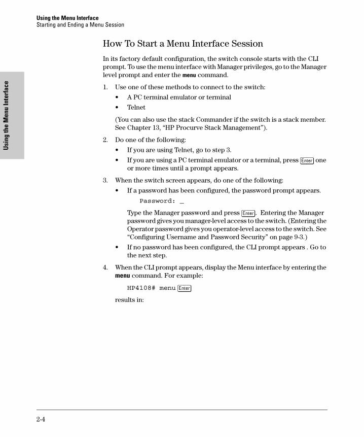
Using the M
enu Interface
Figure 2-1. The Main Menu with Manager Privileges
For a description of Main Menu features, see “Main Menu Features” on page 2-7.
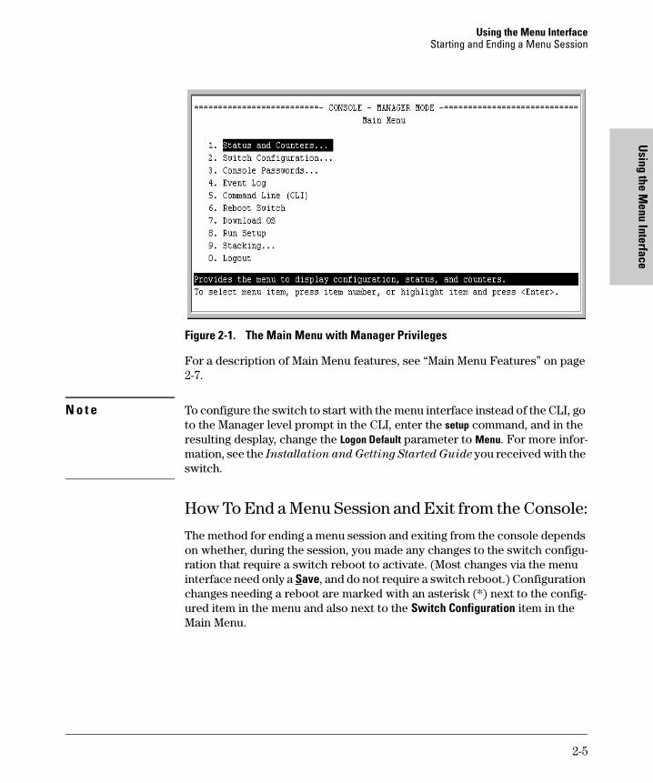
N o t e To configure the switch to start with the menu interface instead of the CLI, go to the Manager level prompt in the CLI, enter the setup command, and in the resulting desplay, change the Logon Default parameter to Menu. For more infor-mation, see the Installation and Getting Started Guide you received with the switch.
How To End a Menu Session and Exit from the Console:
The method for ending a menu session and exiting from the console depends on whether, during the session, you made any changes to the switch configu-ration that require a switch reboot to activate. (Most changes via the menu interface need only a Save, and do not require a switch reboot.) Configuration changes needing a reboot are marked with an asterisk (*) next to the config-ured item in the menu and also next to the Switch Configuration item in the Main Menu.
2-5
Using the Menu InterfaceStarting and Ending a Menu Session
Usi
ng th
e M
enu
Inte
rfac
e
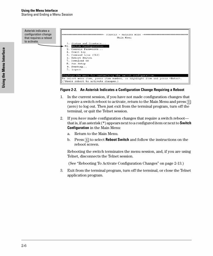
Figure 2-2. An Asterisk Indicates a Configuration Change Requiring a Reboot
1. In the current session, if you have not made configuration changes that require a switch reboot to activate, return to the Main Menu and press [0] (zero) to log out. Then just exit from the terminal program, turn off the terminal, or quit the Telnet session.
2. If you have made configuration changes that require a switch reboot—that is, if an asterisk (*) appears next to a configured item or next to Switch Configuration in the Main Menu:
a. Return to the Main Menu.
b. Press [6] to select Reboot Switch and follow the instructions on the reboot screen.
Rebooting the switch terminates the menu session, and, if you are using Telnet, disconnects the Telnet session.
(See “Rebooting To Activate Configuration Changes” on page 2-13.)
3. Exit from the terminal program, turn off the terminal, or close the Telnet application program.
Asterisk indicates a configuration change that requires a reboot to activate.
2-6
Using the Menu InterfaceMain Menu Features
Using the M
enu Interface
Main Menu Features
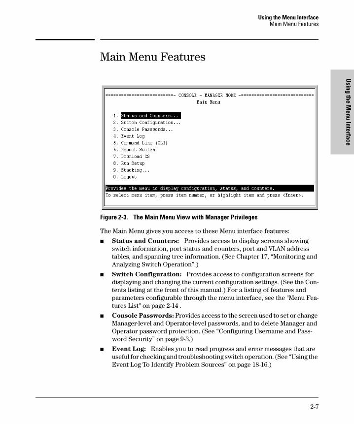
Figure 2-3. The Main Menu View with Manager Privileges
The Main Menu gives you access to these Menu interface features:
� Status and Counters: Provides access to display screens showing switch information, port status and counters, port and VLAN address tables, and spanning tree information. (See Chapter 17, “Monitoring and Analyzing Switch Operation”.)
� Switch Configuration: Provides access to configuration screens for displaying and changing the current configuration settings. (See the Con-tents listing at the front of this manual.) For a listing of features and parameters configurable through the menu interface, see the "Menu Fea-tures List" on page 2-14 .
� Console Passwords: Provides access to the screen used to set or change Manager-level and Operator-level passwords, and to delete Manager and Operator password protection. (See “Configuring Username and Pass-word Security” on page 9-3.)
� Event Log: Enables you to read progress and error messages that are useful for checking and troubleshooting switch operation. (See “Using the Event Log To Identify Problem Sources” on page 18-16.)
2-7
Using the Menu InterfaceMain Menu Features
Usi
ng th
e M
enu
Inte
rfac
e
� Command Line (CLI): Selects the Command Line Interface at the same level (Manager or Operator) that you are accessing in the Menu interface. (See chapter 3, "Using the Command Line Interface (CLI)".)
� Reboot Switch: Performs a "warm" reboot of the switch, which clears most temporary error conditions, resets the network activity counters to zero, and resets the system up-time to zero. A reboot is required to activate a change in the VLAN Support parameter. (See “Rebooting from the Menu Interface” on page 5-9.)
� Download OS: Enables you to download a new software version to the switch. (See Appendix A, “File Transfers”.)
� Run Setup: Displays the Switch Setup screen for quickly configuring basic switch parameters such as IP addressing, default gateway, logon default interface, spanning tree, and others. (See the Installation and
Getting Started guide shipped with your switch.)
� Stacking: Enables you to use a single IP address and standard network cabling to manage a group of up to 16 switches in the same subnet (broadcast domain). See Chapter 13, “HP Procurve Stack Management”.
� Logout: Closes the Menu interface and console session, and disconnects Telnet access to the switch. (See “How to End a Menu Session and Exit from the Console” on page 2-5.)
2-8
Using the Menu InterfaceScreen Structure and Navigation
Using the M
enu Interface
Screen Structure and NavigationMenu interface screens include these three elements:
� Parameter fields and/or read-only information such as statistics
� Navigation and configuration actions, such as Save, Edit, and Cancel
� Help line to describe navigation options, individual parameters, and read-only data
For example, in the following System Information screen:
Figure 2-4. Elements of the Screen Structure
“Forms” Design. The configuration screens, in particular, operate similarly to a number of PC applications that use forms for data entry. When you first enter these screens, you see the current configuration for the item you have selected. To change the configuration, the basic operation is to:
1. Press [E] to select the Edit action.
2. Navigate through the screen making all the necessary configuration changes. (See Table 4-1 on the next page.)
3. Press [Enter] to return to the Actions line. From there you can save the configuration changes or cancel the changes. Cancel returns the configu-ration to the values you saw when you first entered the screen.
Help line describing the selected action or selected parameter field
Parameter fields
Help describing each of the items in the parameter fields
Navigation instructions
Actions line
Screen title – identifies the location within the menu structure
2-9
Using the Menu InterfaceScreen Structure and Navigation
Usi
ng th
e M
enu
Inte
rfac
e
Table 2-1. How To Navigate in the Menu Interface
Task: Actions:
Execute an actionfrom the “Actions –>”list at the bottom ofthe screen:
Use either of the following methods:• Use the arrow keys ( [<] ,or [>] ) to highlight the action you want
to execute, then press [Enter].• Press the key corresponding to the capital letter in the action
name. For example, in a configuration menu, press [E] to select Edit and begin editing parameter values.
Reconfigure (edit) a parameter setting or a field:
1. Select a configuration item, such as System Name. (See figure 4.)2. Press [E] (for Edit on the Actions line).3. Use [Tab] or the arrow keys ([<], [>], [^], or [v]) to highlight the
item or field.4. Do one of the following:
– If the parameter has preconfigured values, either use the Space bar to select a new option or type the first part of your selection and the rest of the selection appears automatically. (The help line instructs you to “Select” a value.)
– If there are no preconfigured values, type in a value (the Help line instructs you to “Enter” a value).
5. If you want to change another parameter value, return to step 3.6. If you are finished editing parameters in the displayed screen,
press [Enter] to return to the Actions line and do one of the following:– To save and activate configuration changes, press [S] (for the
Save action). This saves the changes in the startup configuration and also implements the change in the currently running configuration. (See Chapter 5, “Switch Memory and Configuration”.)
– To exit from the screen without saving any changes that you have made (or if you have not made changes), press [C] (for the Cancel action).
Note: In the menu interface, executing Save activates most parameter changes and saves them in the startup configuration (or flash) memory, and it is therefore not necessary to reboot the switch after making these changes. But if an asterisk appears next to any menu item you reconfigure, the switch will not activate or save the change for that item until you reboot the switch. In this case, rebooting should be done after you have made all desired changes and then returned to the Main Menu.
7. When you finish editing parameters, return to the Main Menu.8. If necessary, reboot the switch by highlighting Reboot Switch in
the Main Menu and pressing [Enter]. (See the Note, above.)
Exit from a read-only screen.
Press [B] (for the Back action).
2-10
Using the Menu InterfaceScreen Structure and Navigation
Using the M
enu Interface
To get Help on individual parameter descriptions. In most screens there is a Help option in the Actions line. Whenever any of the items in the Actions line is highlighted, press [H], and a separate help screen is displayed. For example:
Figure 2-5. Example Showing How To Display Help
To get Help on the actions or data fields in each screen: Use the arrow keys ( [<], [>], [^], or [v]) to select an action or data field. The help line under the Actions items describes the currently selected action or data field.
For guidance on how to navigate in a screen: See the instructions provided at the bottom of the screen, or refer to “Screen Structure and Navigation” on page 2-9.)
Pressing [H] or highlighting Help and pressing [Enter] displays Help for the parameters listed in the upper part of the screen
Highlight on any item in the Actions line indicates that the Actions line is active.
The Help line provides a brief descriptor of the highlighted Action item or parameter.
2-11
Using the Menu InterfaceRebooting the Switch
Usi
ng th
e M
enu
Inte
rfac
e
Rebooting the Switch
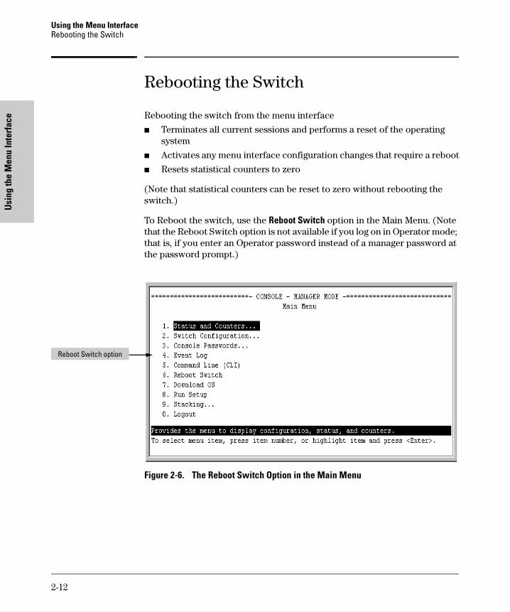
Rebooting the switch from the menu interface
� Terminates all current sessions and performs a reset of the operating system
� Activates any menu interface configuration changes that require a reboot
� Resets statistical counters to zero
(Note that statistical counters can be reset to zero without rebooting the switch.)
To Reboot the switch, use the Reboot Switch option in the Main Menu. (Note that the Reboot Switch option is not available if you log on in Operator mode; that is, if you enter an Operator password instead of a manager password at the password prompt.)
Figure 2-6. The Reboot Switch Option in the Main Menu
Reboot Switch option
2-12
Using the Menu InterfaceRebooting the Switch
Using the M
enu Interface
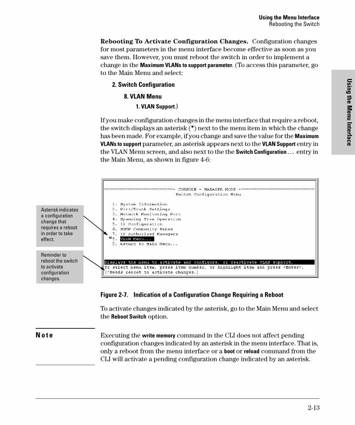
Rebooting To Activate Configuration Changes. Configuration changes for most parameters in the menu interface become effective as soon as you save them. However, you must reboot the switch in order to implement a change in the Maximum VLANs to support parameter. (To access this parameter, go to the Main Menu and select:
2. Switch Configuration
8. VLAN Menu1. VLAN Support.)
If you make configuration changes in the menu interface that require a reboot, the switch displays an asterisk (*) next to the menu item in which the change has been made. For example, if you change and save the value for the Maximum VLANs to support parameter, an asterisk appears next to the VLAN Support entry in the VLAN Menu screen, and also next to the the Switch Configuration . . . entry in the Main Menu, as shown in figure 4-6:
Figure 2-7. Indication of a Configuration Change Requiring a Reboot
To activate changes indicated by the asterisk, go to the Main Menu and select the Reboot Switch option.
N o t e Executing the write memory command in the CLI does not affect pending configuration changes indicated by an asterisk in the menu interface. That is, only a reboot from the menu interface or a boot or reload command from the CLI will activate a pending configuration change indicated by an asterisk.
Reminder to reboot the switch to activate configuration changes.
Asterisk indicates a configuration change that requires a reboot in order to take effect.
2-13
Using the Menu InterfaceMenu Features List
Usi
ng th
e M
enu
Inte
rfac
e
Menu Features List
Status and Counters
• General System Information
• Switch Management Address Information
• Port Status
• Port Counters
• Address Table
• Port Address Table
• Spanning Tree Information
Switch Configuration
• System Information
• Port/Trunk Settings
• Network Monitoring Port
• Spanning Tree Operation
• IP Configuration
• SNMP Community Names
• IP authorized Managers
• VLAN Menu
Console Passwords
Event Log
Command Line (CLI)
Reboot Switch
Download OS
Run Setup
Stacking
• Stacking Status (This Switch)
• Stacking Status (All)
• Stack Configuration
• Stack Management (Available in Stack Commander Only)
• Stack Access (Available in Stack Commander Only)
Logout
2-14
Using the Menu InterfaceWhere To Go From Here
Using the M
enu Interface
Where To Go From Here
This chapter provides an overview of the menu interface and how to use it. The following table indicates where to turn for detailed information on how to use the individual features available through the menu interface.
Option Where To Turn
To use the Run Setup option See the Installation and Getting Started Guide shipped with the switch.
To use the Procurve Stack Manager Chapter 13, “HP Procurve Stack Management”
To view and monitor switch status and counters
Chapter 17, “Monitoring and Analyzing Switch Operation”
To learn how to configure and use passwords
Chapter 9, “Configuring Username and Password Security”
To learn how to use the Event Log “Using the Event Log To Identify Problem Sources” on page 18-16
To learn how the CLI operates Chapter 3, “Using the Command Line Interface (CLI)”
To download software (the OS) Appendix A, “File Transfers”
For a description of how switch memory handles configuration changes
“Switch Memory and Configuration” on page 5-1
For information on other switch features and how to configure them
See the Table of Contents at the front of this manual.
2-15

Using the Menu InterfaceWhere To Go From Here
Usi
ng th
e M
enu
Inte
rfac
e
2-16
Using the Com
mand Line
Interface (CLI)
3
Using the Command Line Interface (CLI)
Chapter Contents
Overview . . . . . . . . . . . . . . . . . . . . . . . . . . . . . . . . . . . . . . . . . . . . . . . . . . . . . . 3-2
Accessing the CLI . . . . . . . . . . . . . . . . . . . . . . . . . . . . . . . . . . . . . . . . . . . . . . . 3-2
Using the CLI . . . . . . . . . . . . . . . . . . . . . . . . . . . . . . . . . . . . . . . . . . . . . . . . . . 3-2
Privilege Levels at Logon . . . . . . . . . . . . . . . . . . . . . . . . . . . . . . . . . . . . . 3-3
Privilege Level Operation . . . . . . . . . . . . . . . . . . . . . . . . . . . . . . . . . . . . . 3-4Operator Privileges . . . . . . . . . . . . . . . . . . . . . . . . . . . . . . . . . . . . . . 3-4Manager Privileges . . . . . . . . . . . . . . . . . . . . . . . . . . . . . . . . . . . . . . . 3-5
How To Move Between Levels . . . . . . . . . . . . . . . . . . . . . . . . . . . . . . . . 3-7
Listing Commands and Command Options . . . . . . . . . . . . . . . . . . . . . . 3-8Listing Commands Available at Any Privilege Level . . . . . . . . . . . 3-8Command Option Displays . . . . . . . . . . . . . . . . . . . . . . . . . . . . . . . 3-10
Displaying CLI "Help" . . . . . . . . . . . . . . . . . . . . . . . . . . . . . . . . . . . . . . . 3-11
Configuration Commands and the Context Configuration Modes . . 3-13
CLI Control and Editing . . . . . . . . . . . . . . . . . . . . . . . . . . . . . . . . . . . . . . . . . 3-16
3-1
Using the Command Line Interface (CLI)Overview
Usi
ng th
e Co
mm
and
Line
In
terf
ace
(CLI
)
Overview
The CLI is a text-based command interface for configuring and monitoring the switch. The CLI gives you access to the switch’s full set of commands while providing the same password protection that is used in the web browser interface and the menu interface.
Accessing the CLI
Like the menu interface, the CLI is accessed through the switch console, and, in the switch’s factory default state, is the default interface when you start a console session. You can access the console out-of-band by directly connecting a terminal device to the switch, or in-band by using Telnet either from a terminal device or through the web browser interface.
Also, if you are using the menu interface, you can access the CLI by selecting the Command Line (CLI) option in the Main Menu.
Using the CLI
The CLI offers these privilege levels to help protect the switch from unautho-rized access:
1. Operator
2. Manager
3. Global Configuration
4. Context Configuration
N o t e CLI commands are not case-sensitive.
When you use the CLI to make a configuration change, the switch writes the change to the Running-Config file in volatile memory. This allows you to test your configuration changes before making them permanent. To make changes permanent, you must use the write memory command to save them to the
3-2
Using the Command Line Interface (CLI)Using the CLI
Using the Com
mand Line
Interface (CLI)
Startup Config file in non-volatile memory. If you reboot the switch without first using write memory, all changes made since the last reboot or write memory (whichever is later) will be lost. For more on switch memory and saving configuration changes, see Chapter 5X, “Switch Memory and Configuration”.
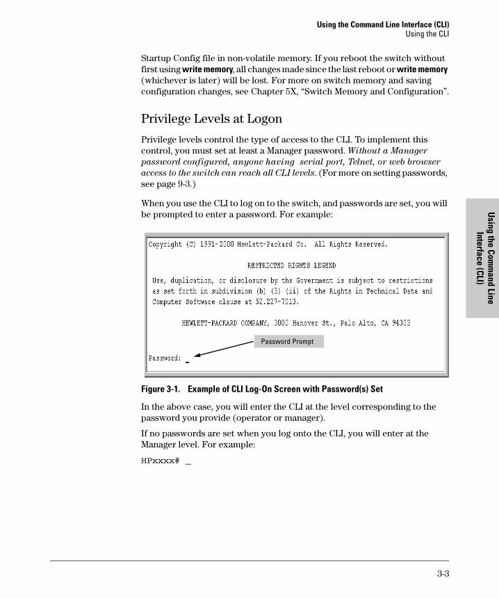
Privilege Levels at Logon
Privilege levels control the type of access to the CLI. To implement this control, you must set at least a Manager password. Without a Manager
password configured, anyone having serial port, Telnet, or web browser
access to the switch can reach all CLI levels. (For more on setting passwords, see page 9-3.)
When you use the CLI to log on to the switch, and passwords are set, you will be prompted to enter a password. For example:
Figure 3-1. Example of CLI Log-On Screen with Password(s) Set
In the above case, you will enter the CLI at the level corresponding to the password you provide (operator or manager).
If no passwords are set when you log onto the CLI, you will enter at the Manager level. For example:
HPxxxx# _
Password Prompt
3-3
Using the Command Line Interface (CLI)Using the CLI
Usi
ng th
e Co
mm
and
Line
In
terf
ace
(CLI
)
C a u t i o n HP strongly recommends that you configure a Manager password. If a Man- ager password is not configured, then the Manager level is not password-protected, and anyone having in-band or out-of-band access to the switch may be able to reach the Manager level and compromise switch and network security. Note that configuring only an Operator password does not prevent access to the Manager level by intruders who have the Operator password.
Pressing the Clear button on the front of the switch removes password protection. For this reason, it is recommended that you protect the switch
from physical access by unauthorized persons. If you are concerned about switch security and operation, you should install the switch in a secure location, such as a locked wiring closet.
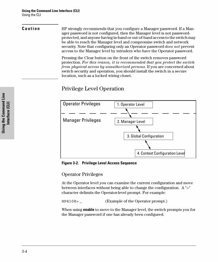
Privilege Level Operation
Figure 3-2. Privilege Level Access Sequence
Operator Privileges
At the Operator level you can examine the current configuration and move between interfaces without being able to change the configuration. A ">" character delimits the Operator-level prompt. For example:
HP4108> _ (Example of the Operator prompt.)
When using enable to move to the Manager level, the switch prompts you for the Manager password if one has already been configured.
2. Manager Level
3. Global Configuration
Operator Privileges
Manager Privileges
1. Operator Level
4. Context Configuration Level
3-4
Using the Command Line Interface (CLI)Using the CLI
Using the Com
mand Line
Interface (CLI)
Manager Privileges
Manager privileges give you three additional levels of access: Manager, Global Configuration, and Context Configuration. (See figure .) A "#" character delimits any Manager prompt. For example:
HP4108#_ (Example of the Manager prompt.)
� Manager level: Provides all Operator level privileges plus the ability to perform system-level actions that do not require saving changes to the system configuration file. The prompt for the Manager level contains only the system name and the "#" delimiter, as shown above. To select this level, enter the enable command at the Operator level prompt and enter the Manager password, when prompted. For example:
HP4108> enable (Enter enable at the Operator prompt.)HP4108# _ (The Manager prompt.)
� Global Configuration level: Provides all Operator and Manager level privileges, and enables you to make configuration changes to any of the switch’s software features. The prompt for the Global Configuration level includes the system name and "(config)". To select this level, enter the config command at the Manager prompt. For example:
HP4108# _ (Enter config at the Manager prompt.)HP4108(config)#_ (The Global Config prompt.)
� Context Configuration level: Provides all Operator and Manager privileges, and enables you to make configuration changes in a specific context, such as one or more ports or a VLAN. The prompt for the Context Configuration level includes the system name and the selected context. For example:
HP4108(eth-1)#
HP4108(vlan-10)#
The Context level is useful, for example, if you want to execute several commands directed at the same port or VLAN, or if you want to shorten the command strings for a specific context area. To select this level, enter the specific context at the Global Configuration level prompt. For example, to select the context level for an existing VLAN with the VLAN ID of 10, you would enter the following command and see the indicated result:
HP4108(config)# vlan 10
HP4108(vlan-10)#
3-5
Using the Command Line Interface (CLI)Using the CLI
Usi
ng th
e Co
mm
and
Line
In
terf
ace
(CLI
)
Changing Interfaces. If you change from the CLI to the menu interface, or the reverse, you will remain at the same privilege level. For example, entering the menu command from the Operator level of the CLI takes you to the Operator privilege level in the menu interface.
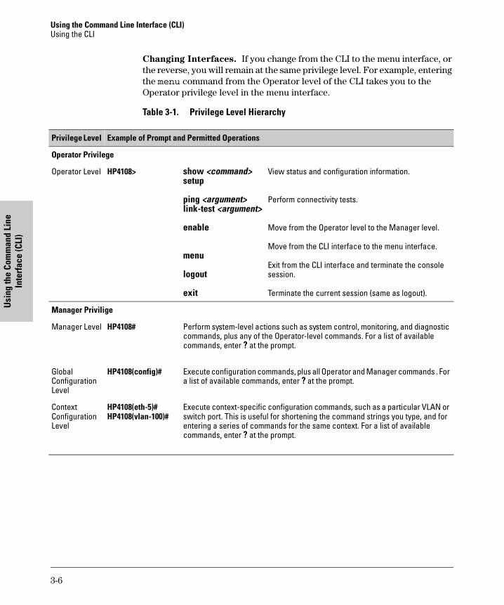
Table 3-1. Privilege Level Hierarchy
Privilege Level Example of Prompt and Permitted Operations
Operator Privilege
Operator Level HP4108> show <command>setup
ping <argument>link-test <argument>
enable
menu
logout
exit
View status and configuration information.
Perform connectivity tests.
Move from the Operator level to the Manager level.
Move from the CLI interface to the menu interface.
Exit from the CLI interface and terminate the console session.
Terminate the current session (same as logout).
Manager Privilige
Manager Level HP4108# Perform system-level actions such as system control, monitoring, and diagnostic commands, plus any of the Operator-level commands. For a list of available commands, enter ? at the prompt.
GlobalConfiguration Level
HP4108(config)# Execute configuration commands, plus all Operator and Manager commands . For a list of available commands, enter ? at the prompt.
Context Configuration Level
HP4108(eth-5)#HP4108(vlan-100)#
Execute context-specific configuration commands, such as a particular VLAN or switch port. This is useful for shortening the command strings you type, and for entering a series of commands for the same context. For a list of available commands, enter ? at the prompt.
3-6
Using the Command Line Interface (CLI)Using the CLI
Using the Com
mand Line
Interface (CLI)
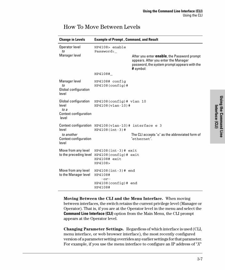
How To Move Between Levels
Moving Between the CLI and the Menu Interface. When moving between interfaces, the switch retains the current privilege level (Manager or Operator). That is, if you are at the Operator level in the menu and select the Command Line Interface (CLI) option from the Main Menu, the CLI prompt appears at the Operator level.
Changing Parameter Settings. Regardless of which interface is used (CLI, menu interface, or web browser interface), the most recently configured version of a parameter setting overrides any earlier settings for that parameter. For example, if you use the menu interface to configure an IP address of "X"
Change in Levels Example of Prompt , Command, and Result
Operator level to Manager level
HP4108> enablePassword:_
After you enter enable, the Password prompt appears. After you enter the Manager password, the system prompt appears with the # symbol:
HP4108#_
Manager level to Global configuration level
HP4108# configHP4108(config)#
Global configuration level to aContext configuration level
HP4108(config)# vlan 10HP4108(vlan-10)#
Context configurationlevel to anotherContext configuration level
HP4108(vlan-10)# interface e 3HP4108(int-3)#
The CLI accepts "e" as the abbreviated form of "ethernet".
Move from any level to the preceding level
HP4108(int-3)# exitHP4108(config)# exitHP4108# exitHP4108>
Move from any level to the Manager level
HP4108(int-3)# endHP4108# —or—HP4108(config)# endHP4108#
3-7
Using the Command Line Interface (CLI)Using the CLI
Usi
ng th
e Co
mm
and
Line
In
terf
ace
(CLI
)
for VLAN 1 and later use the CLI to configure a different IP address of "Y" for VLAN 1, then "Y" replaces "X" as the IP address for VLAN 1 in the running-config file. (If you subsequently execute write memory in the CLI, then the switch also stores "Y" as the IP address for VLAN 1 in the startup-config file. (For more on the startup-config and running config files, see Chapter 5X, “Switch Memory and Configuration”.)
Listing Commands and Command Options
At any privilege level you can:
� List all of the commands available at that level
� List the options for a specific command
Listing Commands Available at Any Privilege Level
At a given privilege level you can list and execute the commands that level offers, plus all of the commands available at preceding levels. For example, at the Operator level, you can list and execute only the Operator level commands. However, at the Manager level, you can list and execute the commands available at both the Operator and Manager levels.
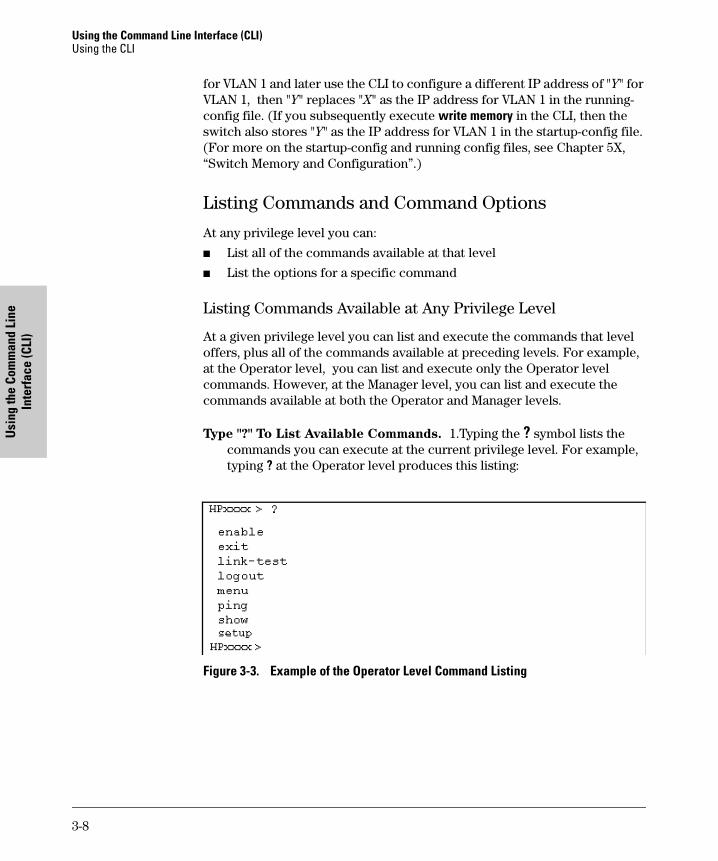
Type "?" To List Available Commands. 1.Typing the ? symbol lists the commands you can execute at the current privilege level. For example, typing ? at the Operator level produces this listing:
Figure 3-3. Example of the Operator Level Command Listing
3-8
Using the Command Line Interface (CLI)Using the CLI
Using the Com
mand Line
Interface (CLI)
Typing ? at the Manager level produces this listing:
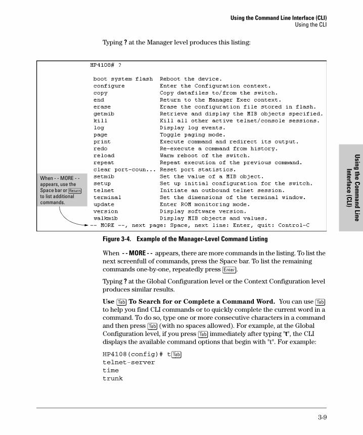
Figure 3-4. Example of the Manager-Level Command Listing
When - - MORE - - appears, there are more commands in the listing. To list the next screenfull of commands, press the Space bar. To list the remaining commands one-by-one, repeatedly press [Enter].
Typing ? at the Global Configuration level or the Context Configuration level produces similar results.
Use [Tab] To Search for or Complete a Command Word. You can use [Tab] to help you find CLI commands or to quickly complete the current word in a command. To do so, type one or more consecutive characters in a command and then press [Tab] (with no spaces allowed). For example, at the Global Configuration level, if you press [Tab] immediately after typing "t", the CLI displays the available command options that begin with "t". For example:
HP4108(config)# t[Tab]telnet-server
time
trunk
When - - MORE - - appears, use the Space bar or [Return] to list additional commands.
3-9
Using the Command Line Interface (CLI)Using the CLI
Usi
ng th
e Co
mm
and
Line
In
terf
ace
(CLI
)
telnet
terminal
HP4108(config)# t
As mentioned above, if you type part of a command word and press [Tab], the CLI completes the current word (if you have typed enough of the word for the CLI to distinguish it from other possibilities), including hyphenated exten-sions. For example:
HP4108(config)# port[Tab]HP4108(config)# port-security _
Pressing [Tab] after a completed command word lists the further options for that command.
HP4108(config)# stack [Tab] commander <commander-str>
join <mac-addr>
auto-join
transmission-interval <integer>
<cr>
HP4108(config)# stack
Command Option Displays
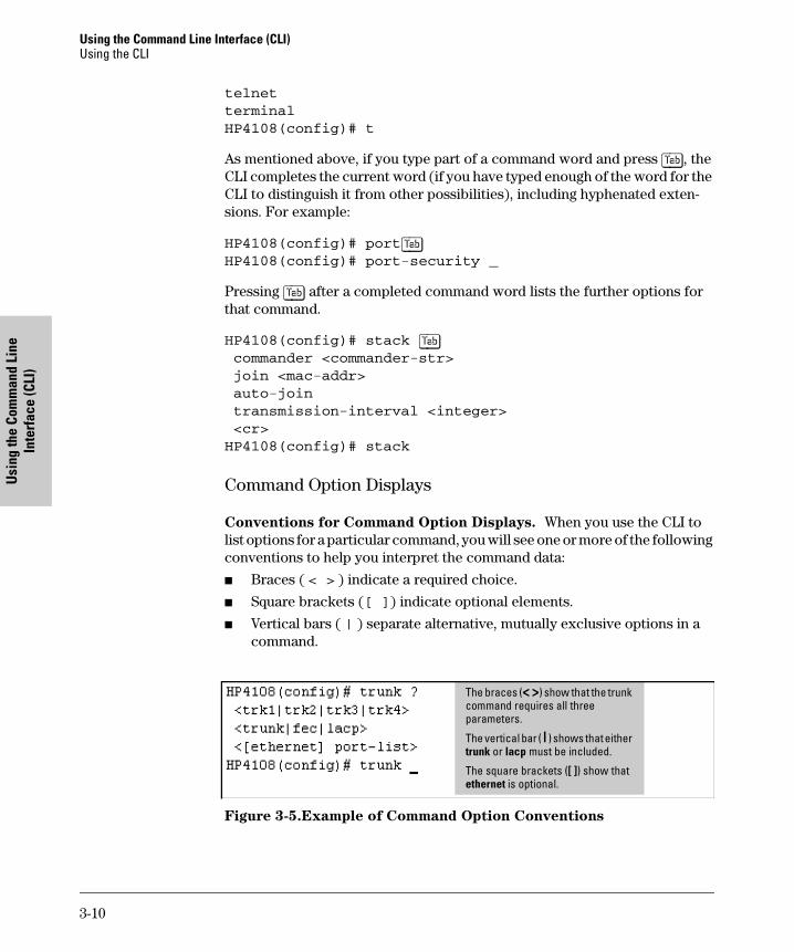
Conventions for Command Option Displays. When you use the CLI to list options for a particular command, you will see one or more of the following conventions to help you interpret the command data:
� Braces ( < > ) indicate a required choice.
� Square brackets ([ ]) indicate optional elements.
� Vertical bars ( | ) separate alternative, mutually exclusive options in a command.
Figure 3-5.Example of Command Option Conventions
The braces (< >) show that the trunk command requires all three parameters.
The vertical bar ( | ) shows that either trunk or lacp must be included.
The square brackets ([ ]) show that ethernet is optional.
3-10
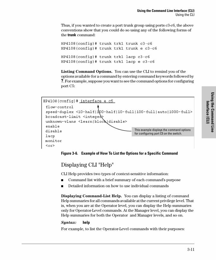
Using the Command Line Interface (CLI)Using the CLI
Using the Com
mand Line
Interface (CLI)
Thus, if you wanted to create a port trunk group using ports c3-c6, the above conventions show that you could do so using any of the following forms of the trunk command:
HP4108(config)# trunk trk1 trunk c3-c6
HP4108(config)# trunk trk1 trunk e c3-c6
HP4108(config)# trunk trk1 lacp c3-c6
HP4108(config)# trunk trk1 lacp e c3-c6
Listing Command Options. You can use the CLI to remind you of the options available for a command by entering command keywords followed by ?. For example, suppose you want to see the command options for configuring port C5:
Figure 3-6. Example of How To List the Options for a Specific Command
Displaying CLI "Help"
CLI Help provides two types of context-sensitive information:
� Command list with a brief summary of each command’s purpose
� Detailed information on how to use individual commands
Displaying Command-List Help. You can display a listing of command Help summaries for all commands available at the current privilege level. That is, when you are at the Operator level, you can display the Help summaries only for Operator-Level commands. At the Manager level, you can display the Help summaries for both the Operator and Manager levels, and so on.
Syntax: help
For example, to list the Operator-Level commands with their purposes:
This example displays the command options for configuring port C5 on the switch.
3-11
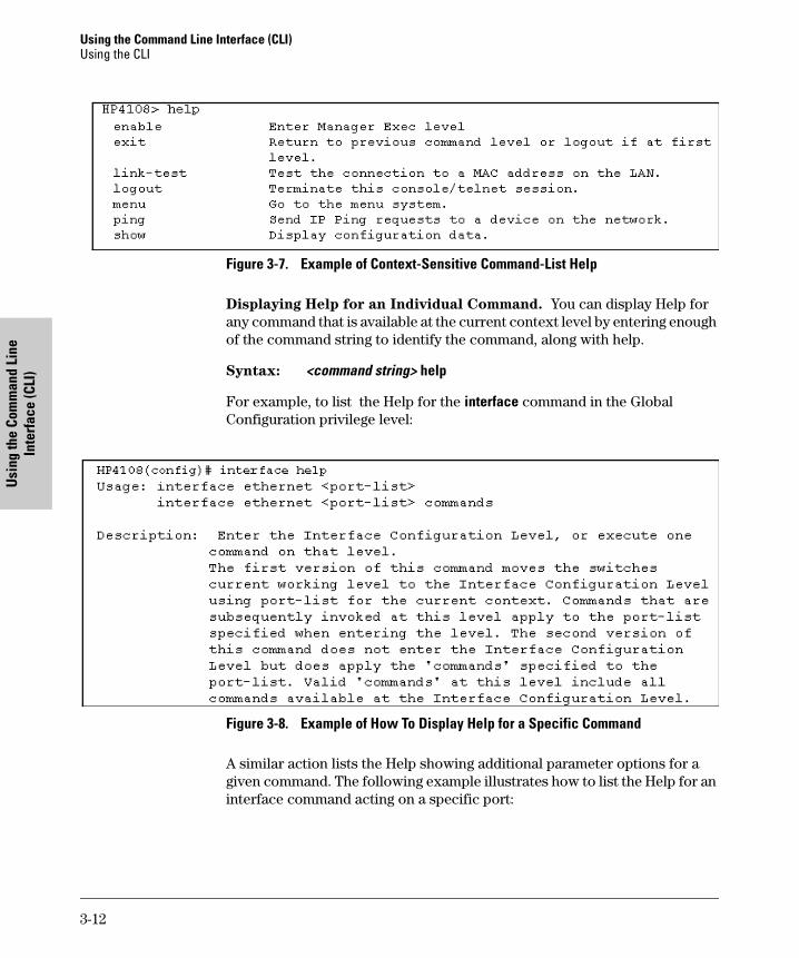
Using the Command Line Interface (CLI)Using the CLI
Usi
ng th
e Co
mm
and
Line
In
terf
ace
(CLI
)
Figure 3-7. Example of Context-Sensitive Command-List Help
Displaying Help for an Individual Command. You can display Help for any command that is available at the current context level by entering enough of the command string to identify the command, along with help.
Syntax: <command string> help
For example, to list the Help for the interface command in the Global Configuration privilege level:
Figure 3-8. Example of How To Display Help for a Specific Command
A similar action lists the Help showing additional parameter options for a given command. The following example illustrates how to list the Help for an interface command acting on a specific port:
3-12
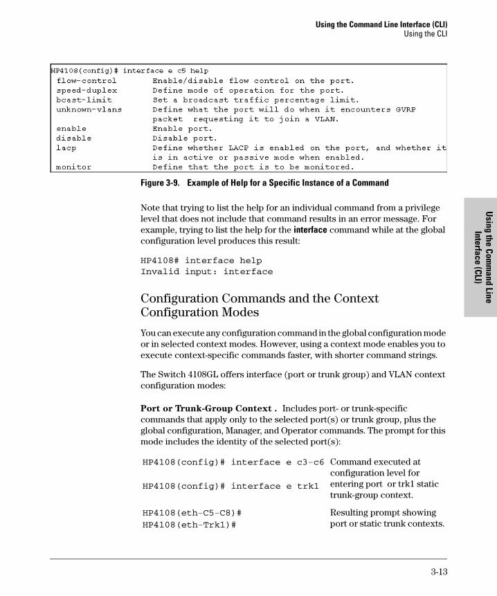
Using the Command Line Interface (CLI)Using the CLI
Using the Com
mand Line
Interface (CLI)
Figure 3-9. Example of Help for a Specific Instance of a Command
Note that trying to list the help for an individual command from a privilege level that does not include that command results in an error message. For example, trying to list the help for the interface command while at the global configuration level produces this result:
HP4108# interface help
Invalid input: interface
Configuration Commands and the Context Configuration Modes
You can execute any configuration command in the global configuration mode or in selected context modes. However, using a context mode enables you to execute context-specific commands faster, with shorter command strings.
The Switch 4108GL offers interface (port or trunk group) and VLAN context configuration modes:
Port or Trunk-Group Context . Includes port- or trunk-specific commands that apply only to the selected port(s) or trunk group, plus the global configuration, Manager, and Operator commands. The prompt for this mode includes the identity of the selected port(s):
HP4108(config)# interface e c3-c6
HP4108(config)# interface e trk1
Command executed at configuration level for entering port or trk1 static trunk-group context.
HP4108(eth-C5-C8)#
HP4108(eth-Trk1)#
Resulting prompt showing port or static trunk contexts.
3-13
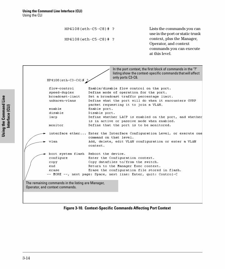
Using the Command Line Interface (CLI)Using the CLI
Usi
ng th
e Co
mm
and
Line
In
terf
ace
(CLI
)
Figure 3-10. Context-Specific Commands Affecting Port Context
HP4108(eth-C5-C8)# ?
HP4108(eth-C5-C8)# ?
Lists the commands you can use in the port or static trunk context, plus the Manager, Operator, and context commands you can execute at this level.
In the port context, the first block of commands in the "?" listing show the context-specific commands that will affect only ports C3-C6.
The remaining commands in the listing are Manager, Operator, and context commands.
3-14
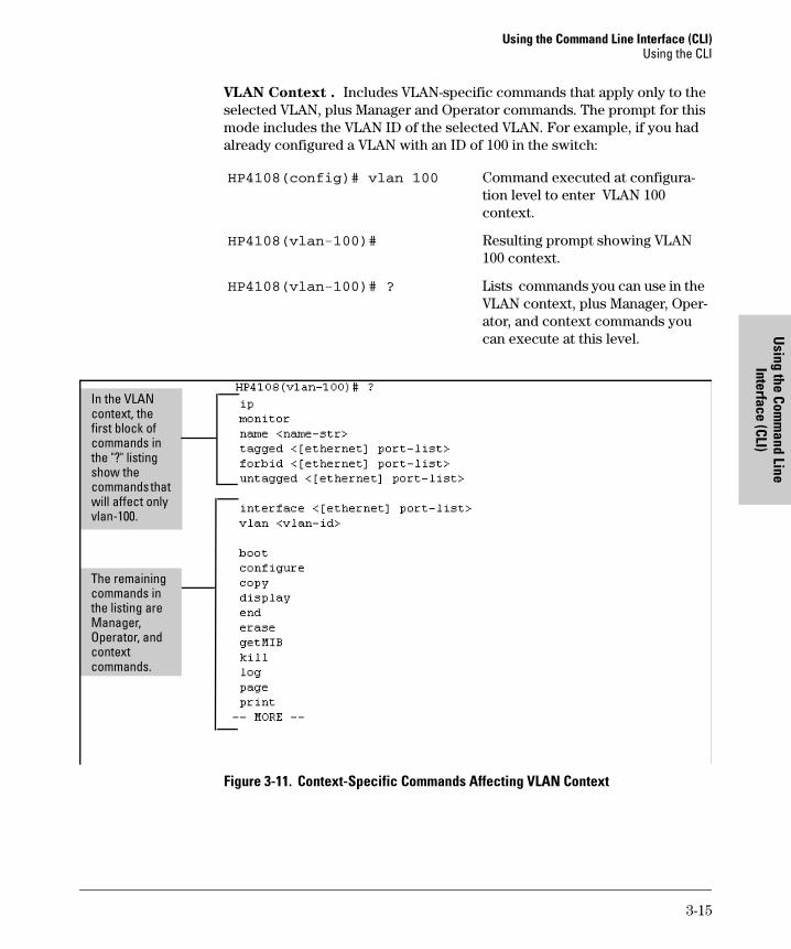
Using the Command Line Interface (CLI)Using the CLI
Using the Com
mand Line
Interface (CLI)
VLAN Context . Includes VLAN-specific commands that apply only to the selected VLAN, plus Manager and Operator commands. The prompt for this mode includes the VLAN ID of the selected VLAN. For example, if you had already configured a VLAN with an ID of 100 in the switch:
Figure 3-11. Context-Specific Commands Affecting VLAN Context
HP4108(config)# vlan 100 Command executed at configura-tion level to enter VLAN 100 context.
HP4108(vlan-100)# Resulting prompt showing VLAN 100 context.
HP4108(vlan-100)# ? Lists commands you can use in the VLAN context, plus Manager, Oper-ator, and context commands you can execute at this level.
In the VLAN context, the first block of commands in the "?" listing show the commands that will affect only vlan-100.
The remaining commands in the listing are Manager, Operator, and context commands.
3-15
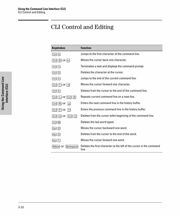
Using the Command Line Interface (CLI)CLI Control and Editing
Usi
ng th
e Co
mm
and
Line
In
terf
ace
(CLI
)
CLI Control and Editing
Keystrokes Function
[Ctrl] [A] Jumps to the first character of the command line.
[Ctrl] [B] or [<] Moves the cursor back one character.
[Ctrl] [C] Terminates a task and displays the command prompt.
[Ctrl] [D] Deletes the character at the cursor.
[Ctrl] [E] Jumps to the end of the current command line.
[Ctrl] [F] or [>] Moves the cursor forward one character.
[Ctrl] [K] Deletes from the cursor to the end of the command line.
[Ctrl] [L] or [Ctrl] [R] Repeats current command line on a new line.
[Ctrl] [N] or [v] Enters the next command line in the history buffer.
[Ctrl] [P] or [^] Enters the previous command line in the history buffer.
[Ctrl] [U] or [Ctrl] [X] Deletes from the cursor tothe beginning of the command line.
[Ctrl] [W] Deletes the last word typed.
[Esc] [B] Moves the cursor backward one word.
[Esc] [D] Deletes from the cursor to the end of the word.
[Esc] [F] Moves the cursor forward one word.
[Delete] or [Backspace] Deletes the first character to the left of the cursor in the command line.
3-16
Using the H
P Web B
rowser
Interface
4
Using the HP Web Browser Interface
Chapter ContentsOverview . . . . . . . . . . . . . . . . . . . . . . . . . . . . . . . . . . . . . . . . . . . . . . . . . . . . . . 4-2
General Features . . . . . . . . . . . . . . . . . . . . . . . . . . . . . . . . . . . . . . . . . . . . . . . 4-3
Web Browser Interface Requirements . . . . . . . . . . . . . . . . . . . . . . . . . . . . . . 4-4
Starting an HP Web Browser Interface Session with the Switch . . . . . . . . 4-5
Using a Standalone Web Browser in a PC or UNIX Workstation . . . . 4-5
Using HP TopTools for Hubs & Switches . . . . . . . . . . . . . . . . . . . . . . . 4-6
Tasks for Your First HP Web Browser Interface Session . . . . . . . . . . . . . . 4-8
Viewing the “First Time Install” Window . . . . . . . . . . . . . . . . . . . . . . . . 4-8
Creating Usernames and Passwords in the Browser Interface . . . . . . 4-9Using the Passwords . . . . . . . . . . . . . . . . . . . . . . . . . . . . . . . . . . . . 4-11Using the User Names . . . . . . . . . . . . . . . . . . . . . . . . . . . . . . . . . . . 4-11If You Lose a Password . . . . . . . . . . . . . . . . . . . . . . . . . . . . . . . . . . 4-12
Online Help for the HP Web Browser Interface . . . . . . . . . . . . . . . . . 4-12
Support/Mgmt URLs Feature . . . . . . . . . . . . . . . . . . . . . . . . . . . . . . . . . . . . 4-13
Support URL . . . . . . . . . . . . . . . . . . . . . . . . . . . . . . . . . . . . . . . . . . . . . . 4-14
Help and the Management Server URL . . . . . . . . . . . . . . . . . . . . . . . . 4-14
Status Reporting Features . . . . . . . . . . . . . . . . . . . . . . . . . . . . . . . . . . . . . . . 4-16
The Overview Window . . . . . . . . . . . . . . . . . . . . . . . . . . . . . . . . . . . . . . 4-16
The Port Utilization and Status Displays . . . . . . . . . . . . . . . . . . . . . . . 4-17Port Utilization . . . . . . . . . . . . . . . . . . . . . . . . . . . . . . . . . . . . . . . . . 4-17Port Status . . . . . . . . . . . . . . . . . . . . . . . . . . . . . . . . . . . . . . . . . . . . . 4-19
The Alert Log . . . . . . . . . . . . . . . . . . . . . . . . . . . . . . . . . . . . . . . . . . . . . . 4-20Sorting the Alert Log Entries . . . . . . . . . . . . . . . . . . . . . . . . . . . . . 4-20Alert Types . . . . . . . . . . . . . . . . . . . . . . . . . . . . . . . . . . . . . . . . . . . . 4-21Viewing Detail Views of Alert Log Entries . . . . . . . . . . . . . . . . . . 4-22
The Status Bar . . . . . . . . . . . . . . . . . . . . . . . . . . . . . . . . . . . . . . . . . . . . . 4-23
Setting Fault Detection Policy . . . . . . . . . . . . . . . . . . . . . . . . . . . . . . . . 4-24
4-1
Using the HP Web Browser InterfaceOverview
Usin
g th
e H
P W
eb B
row
ser
Inte
rfac
e
Overview
The HP web browser interface built into the switch lets you easily access the switch from a browser-based PC on your network. This lets you do the following:
� Optimize your network uptime by using the Alert Log and other diagnostic tools
� Make configuration changes to the switch
� Maintain security by configuring usernames and passwords
This chapter covers the following:
� General features (page 4-3).
� System requirements for using the web browser interface (page 4-4)
� Starting a web browser interface session (page 4-5)
� Tasks for your first web browser interface session (page 4-8):
• Creating usernames and passwords in the web browser interface (page 4-9)
• Selecting the fault detection configuration for the Alert Log operation (page 4-24)
• Getting access to online help for the web browser interface (page 4-12)
� Description of the web browser interface:
• Overview window and tabs (page 4-16)
• Port Utilization and Status displays (page 4-17)
• Alert Log and Alert types (page 4-20)
• Setting the Fault Detection Policy (page 4-24)
N o t e If you want security beyond that achieved with user names and passwords, you can disable access to the web browser interface. This is done by either executing no web-management at the Command Prompt or changing the Web Agent Enabled parameter setting to No (page 6-4).
4-2
Using the HP Web Browser InterfaceGeneral Features
Using the H
P Web B
rowser
Interface
General Features
The Switch 4108GL include these web browser interface features:
Switch Configuration:
• Ports
• VLANs and Primary VLAN
• Fault detection
• Port monitoring (mirroring)
• System information
• Enable/Disable Multicast Filtering (IGMP) and Spanning Tree
• IP
• Stacking
• Support and management URLs
Switch Security: Passwords
Switch Diagnostics:
• Ping/Link Test
• Device reset
• Configuration report
Switch status
• Port utilization
• Port counters
• Port status
• Alert log
Switch system information listing
4-3
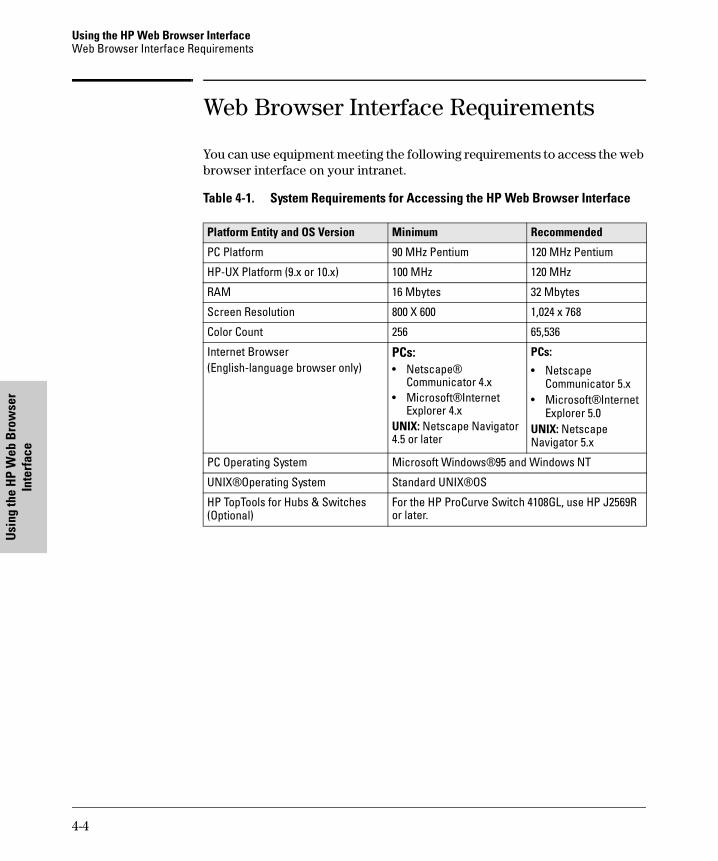
Using the HP Web Browser InterfaceWeb Browser Interface Requirements
Usin
g th
e H
P W
eb B
row
ser
Inte
rfac
e
Web Browser Interface Requirements
You can use equipment meeting the following requirements to access the web browser interface on your intranet.
Table 4-1. System Requirements for Accessing the HP Web Browser Interface
Platform Entity and OS Version Minimum Recommended
PC Platform 90 MHz Pentium 120 MHz Pentium
HP-UX Platform (9.x or 10.x) 100 MHz 120 MHz
RAM 16 Mbytes 32 Mbytes
Screen Resolution 800 X 600 1,024 x 768
Color Count 256 65,536
Internet Browser (English-language browser only)
PCs:• Netscape®
Communicator 4.x• Microsoft® Internet
Explorer 4.xUNIX: Netscape Navigator 4.5 or later
PCs:
• Netscape Communicator 5.x
• Microsoft® Internet Explorer 5.0
UNIX: Netscape Navigator 5.x
PC Operating System Microsoft Windows® 95 and Windows NT
UNIX® Operating System Standard UNIX® OS
HP TopTools for Hubs & Switches (Optional)
For the HP ProCurve Switch 4108GL, use HP J2569R or later.
4-4
Using the HP Web Browser InterfaceStarting an HP Web Browser Interface Session with the Switch
Using the H
P Web B
rowser
Interface
Starting an HP Web Browser Interface Session with the Switch
You can start a web browser session in the following ways:
� Using a standalone web browser on a network connection from a PC or UNIX workstation:
• Directly connected to your network
• Connected through remote access to your network
� Using a management station running HP TopTools for Hubs & Switches on your network
Using a Standalone Web Browser in a PC or UNIX Workstation
This procedure assumes that you have a supported web browser (page 4-4) installed on your PC or workstation, and that an IP address has been config-ured on the switch. (For more on assigning an IP address, refer to "IP Configuration" on page 7-3.)
1. Make sure the JavaTM applets are enabled for your browser. If they are not, use the options menu in your browser to do the following:
• In Netscape, enable the Java and JavaScript options.
• In Microsoft Internet Explorer, enable the Java Permissions.
Refer to your selected browser’s online Help for specific information on enabling the Java applets.
4-5
Using the HP Web Browser InterfaceStarting an HP Web Browser Interface Session with the Switch
Usin
g th
e H
P W
eb B
row
ser
Inte
rfac
e
2. Type the IP address (or DNS name) of the switch in the browser Location or Address field and press [Enter]. (It is not necessary to include http://.)
switch4108 [Enter] (example of a DNS-type name)
10.11.12.195 [Enter] (example of an IP address)
If you are using a Domain Name Server (DNS), your device may have a name associated with it (for example, switch4108) that you can type in the Location or Address field instead of the IP address. Using DNS names typically improves browser performance. See your network administrator for any name associated with the switch.
Using HP TopTools for Hubs & Switches
HP TopTools for Hubs & Switches is designed for installation on a network management workstation. For this reason, the HP TopTools system require-ments are different from the system requirements for accessing the switch’s web browser interface from a non-management PC or workstation. For HP TopTools requirements, refer to the information provided with HP TopTools for Hubs & Switches.
This procedure assumes that:
� You have installed the recommended web browser on a PC or workstation that serves as your network management station.
� The networked device you want to access has been assigned an IP address and (optionally) a DNS name and has been discovered by HP TopTools for Hubs & Switches. (For more on assigning an IP address, refer to "IP Configuration" on page 7-3.)
To establish a web browser session with HP TopTools running, do the following on the network management station:
1. Make sure the JavaTM applets are enabled for your web browser. If they are not, refer to the web browser online Help for specific information on enabling the Java applets.
2. Do one of the following tasks:
• On the HP TopTools Maps view, double-click on the symbol for the networking device that you want to access.
• In HP TopTools, in the Topology Information dialog box, in the device list, double-click on the entry for the device you want to access (IP address or DNS name).
4-6
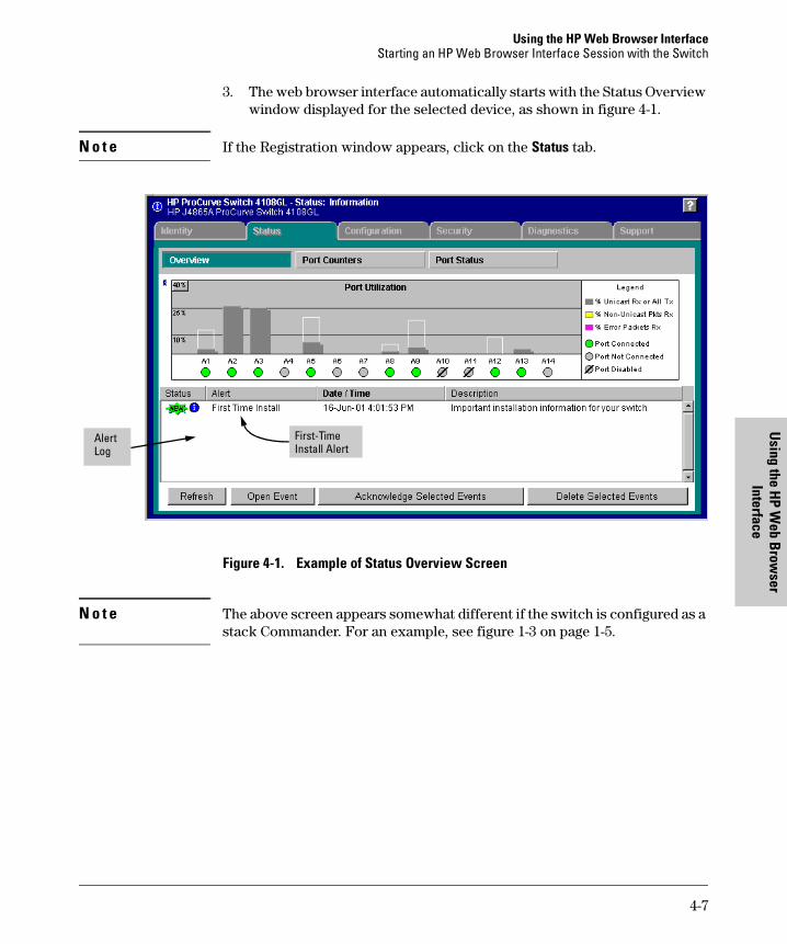
Using the HP Web Browser InterfaceStarting an HP Web Browser Interface Session with the Switch
Using the H
P Web B
rowser
Interface
3. The web browser interface automatically starts with the Status Overview window displayed for the selected device, as shown in figure 4-1.
N o t e If the Registration window appears, click on the Status tab.
Figure 4-1. Example of Status Overview Screen
N o t e The above screen appears somewhat different if the switch is configured as a stack Commander. For an example, see figure 1-3 on page 1-5.
Alert Log
First-TimeInstall Alert
4-7
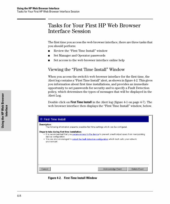
Using the HP Web Browser InterfaceTasks for Your First HP Web Browser Interface Session
Usin
g th
e H
P W
eb B
row
ser
Inte
rfac
e
Tasks for Your First HP Web Browser Interface Session
The first time you access the web browser interface, there are three tasks that you should perform:
� Review the “First Time Install” window
� Set Manager and Operator passwords
� Set access to the web browser interface online help
Viewing the “First Time Install” Window
When you access the switch’s web browser interface for the first time, the Alert log contains a “First Time Install” alert, as shown in figure 4-2. This gives you information about first time installations, and provides an immediate opportunity to set passwords for security and to specify a Fault Detection policy, which determines the types of messages that will be displayed in the Alert Log.
Double click on First Time Install in the Alert log (figure 4-1 on page 4-7). The web browser interface then displays the “First Time Install” window, below.
Figure 4-2. First-Time Install Window
4-8
Using the HP Web Browser InterfaceTasks for Your First HP Web Browser Interface Session
Using the H
P Web B
rowser
Interface
This window is the launching point for the basic configuration you need to perform to set web browser interface passwords to maintain security and Fault Detection policy, which determines the types of messages that will be displayed in the Alert Log.
To set web browser interface passwords, click on secure access to the device to display the Device Passwords screen, and then go to the next page. (You can also access the password screen by clicking on the Security tab.)
To set Fault Detection policy, click on select the fault detection configuration in the second bullet in the window and go to the section, “Setting Fault Detection Policy” on page 4-24. (You can also access the password screen by clicking on the Configuration tab, and then [Fault Detection] button.)
Creating Usernames and Passwords in the Browser Interface
You may want to create both a username and password to create access security for your switch. There are two levels of access to the interface that can be controlled by setting user names and passwords:
� Operator. An Operator-level user name and password allows read-only access to most of the web browser interface, but prevents access to the Security window.
� Manager. A Manager-level user name and password allows full read/write access to the web browser interface.
4-9
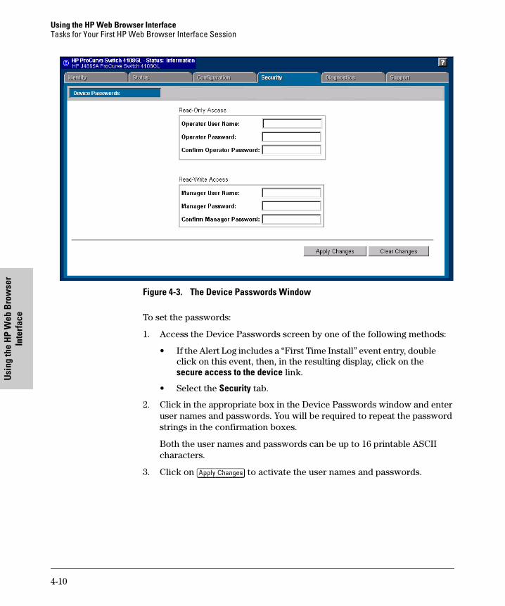
Using the HP Web Browser InterfaceTasks for Your First HP Web Browser Interface Session
Usin
g th
e H
P W
eb B
row
ser
Inte
rfac
e
Figure 4-3. The Device Passwords Window
To set the passwords:
1. Access the Device Passwords screen by one of the following methods:
• If the Alert Log includes a “First Time Install” event entry, double click on this event, then, in the resulting display, click on the secure access to the device link.
• Select the Security tab.
2. Click in the appropriate box in the Device Passwords window and enter user names and passwords. You will be required to repeat the password strings in the confirmation boxes.
Both the user names and passwords can be up to 16 printable ASCII characters.
3. Click on [Apply Changes] to activate the user names and passwords.
4-10
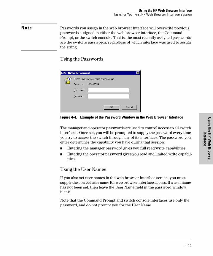
Using the HP Web Browser InterfaceTasks for Your First HP Web Browser Interface Session
Using the H
P Web B
rowser
Interface
N o t e Passwords you assign in the web browser interface will overwrite previous passwords assigned in either the web browser interface, the Command Prompt, or the switch console. That is, the most recently assigned passwords are the switch’s passwords, regardless of which interface was used to assign the string.
Using the Passwords
Figure 4-4. Example of the Password Window in the Web Browser Interface
The manager and operator passwords are used to control access to all switch interfaces. Once set, you will be prompted to supply the password every time you try to access the switch through any of its interfaces. The password you enter determines the capability you have during that session:
� Entering the manager password gives you full read/write capabilities
� Entering the operator password gives you read and limited write capabil-ities.
Using the User Names
If you also set user names in the web browser interface screen, you must supply the correct user name for web browser interface access. If a user name has not been set, then leave the User Name field in the password window blank.
Note that the Command Prompt and switch console interfaces use only the password, and do not prompt you for the User Name.
4-11
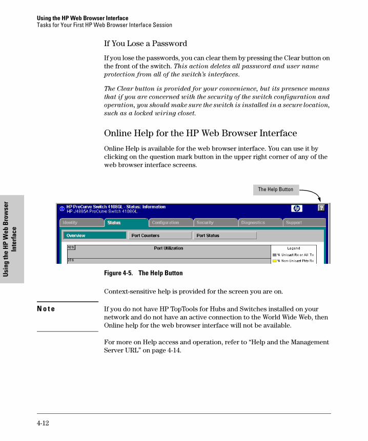
Using the HP Web Browser InterfaceTasks for Your First HP Web Browser Interface Session
Usin
g th
e H
P W
eb B
row
ser
Inte
rfac
e
If You Lose a Password
If you lose the passwords, you can clear them by pressing the Clear button on the front of the switch. This action deletes all password and user name
protection from all of the switch’s interfaces.
The Clear button is provided for your convenience, but its presence means
that if you are concerned with the security of the switch configuration and
operation, you should make sure the switch is installed in a secure location,
such as a locked wiring closet.
Online Help for the HP Web Browser Interface
Online Help is available for the web browser interface. You can use it by clicking on the question mark button in the upper right corner of any of the web browser interface screens.
Figure 4-5. The Help Button
Context-sensitive help is provided for the screen you are on.
N o t e If you do not have HP TopTools for Hubs and Switches installed on your network and do not have an active connection to the World Wide Web, then Online help for the web browser interface will not be available.
For more on Help access and operation, refer to “Help and the Management Server URL” on page 4-14.
The Help Button
4-12
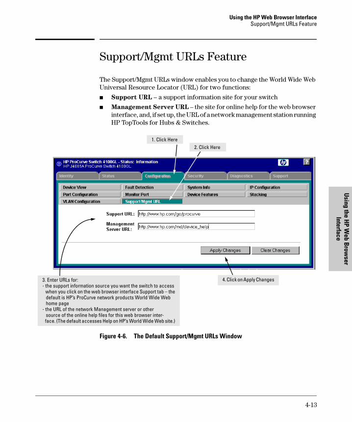
Using the HP Web Browser InterfaceSupport/Mgmt URLs Feature
Using the H
P Web B
rowser
Interface
Support/Mgmt URLs Feature
The Support/Mgmt URLs window enables you to change the World Wide Web Universal Resource Locator (URL) for two functions:
� Support URL – a support information site for your switch
� Management Server URL – the site for online help for the web browser interface, and, if set up, the URL of a network management station running HP TopTools for Hubs & Switches.
Figure 4-6. The Default Support/Mgmt URLs Window
3. Enter URLs for:- the support information source you want the switch to access when you click on the web browser interface Support tab – the default is HP’s ProCurve network products World Wide Web home page- the URL of the network Management server or other source of the online help files for this web browser inter- face. (The default accesses Help on HP’s World Wide Web site.)
1. Click Here2. Click Here
4. Click on Apply Changes
4-13
Using the HP Web Browser InterfaceSupport/Mgmt URLs Feature
Usin
g th
e H
P W
eb B
row
ser
Inte
rfac
e
Support URL
This is the site that the switch accesses when you click on the Support tab on the web browser interface. The default URL is:
http://www.hp.com/go/procurve
which is the World Wide Web site for Hewlett-Packard’s networking products.
Click on the [Support] button on that page and you can get to support information regarding your switch, including white papers, operating system (OS) updates, and more.
You could instead enter the URL for a local site that you use for entering reports about network performance, or whatever other function you would like to be able to easily access by clicking on the [Support] tab.
Help and the Management Server URL
This field specifies which of the following two locations the switch will use to find online Help for the web browser interface:
� The URL of online Help provided by HP on the world wide web
� The URL of a network management station running HP TopTools for Hubs & Switches
Providing Online Help. The Help files are automatically available if you
install HP TopTools for Hubs & Switches on your network or if you already
have Internet access to the World Wide Web. (The Help files are included with HP TopTools for Hubs & Switches, and are also automatically available from HP via the World Wide Web.)
Retrieval of the Help files is controlled by automatic entries to the Management Server URL field on the Configuration / Support/Mgmt URLs screen, shown in figure 4-6. The switch is shipped with the URL set to retrieve online Help from the HP World Wide Web site. However, if HP TopTools for Hubs & Switches is installed on a management station on your network and discovers the switch, the Management Server URL is automatically changed to retrieve the Help from your TopTools management station.
If Online Help Fails To Operate. Do one of the following:
� If HP TopTools for Hubs & Switches is installed and running on your network, enter the IP address or DNS name of the network management station in the Management Server URL field shown in figure 4-7 on page 4-15.
4-14
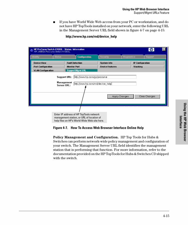
Using the HP Web Browser InterfaceSupport/Mgmt URLs Feature
Using the H
P Web B
rowser
Interface
� If you have World Wide Web access from your PC or workstation, and do not have HP TopTools installed on your network, enter the following URL in the Management Server URL field shown in figure 4-7 on page 4-15:
http://www.hp.com/rnd/device_help
Figure 4-7. How To Access Web Browser Interface Online Help
Policy Management and Configuration. HP Top Tools for Hubs & Switches can perform network-wide policy management and configuration of your switch. The Management Server URL field identifies the management station that is performing that function. For more information, refer to the documentation provided on the HP TopTools for Hubs & Switches CD shipped with the switch.
Enter IP address of HP TopTools network management station, or URL of location of help files on HP’s World Wide Web site here.
4-15
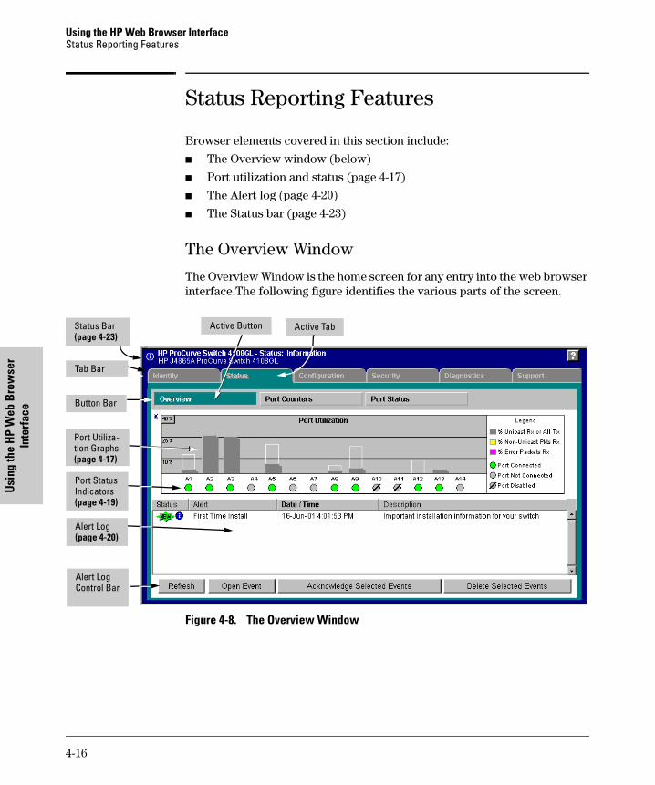
Using the HP Web Browser InterfaceStatus Reporting Features
Usin
g th
e H
P W
eb B
row
ser
Inte
rfac
e
Status Reporting Features
Browser elements covered in this section include:
� The Overview window (below)
� Port utilization and status (page 4-17)
� The Alert log (page 4-20)
� The Status bar (page 4-23)
The Overview Window
The Overview Window is the home screen for any entry into the web browser interface.The following figure identifies the various parts of the screen.
Figure 4-8. The Overview Window
Alert Log Control Bar
Port Utiliza-tion Graphs(page 4-17)
Active TabActive Button
Alert Log (page 4-20)
Port Status Indicators(page 4-19)
Button Bar
Tab Bar
Status Bar(page 4-23)
4-16
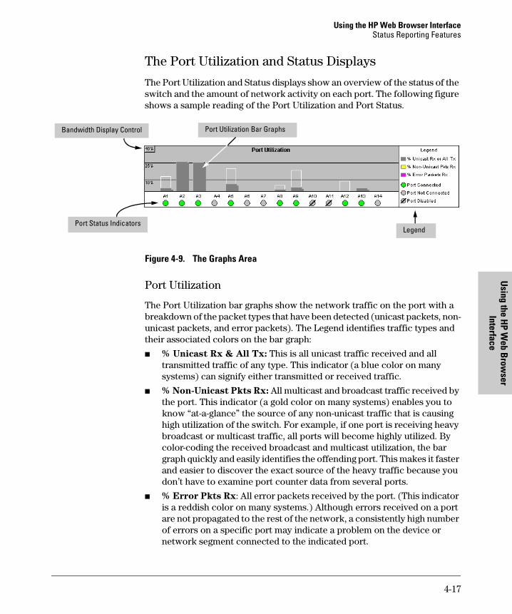
Using the HP Web Browser InterfaceStatus Reporting Features
Using the H
P Web B
rowser
Interface
The Port Utilization and Status Displays
The Port Utilization and Status displays show an overview of the status of the switch and the amount of network activity on each port. The following figure shows a sample reading of the Port Utilization and Port Status.
Figure 4-9. The Graphs Area
Port Utilization
The Port Utilization bar graphs show the network traffic on the port with a breakdown of the packet types that have been detected (unicast packets, non-unicast packets, and error packets). The Legend identifies traffic types and their associated colors on the bar graph:
� % Unicast Rx & All Tx: This is all unicast traffic received and all transmitted traffic of any type. This indicator (a blue color on many systems) can signify either transmitted or received traffic.
� % Non-Unicast Pkts Rx: All multicast and broadcast traffic received by the port. This indicator (a gold color on many systems) enables you to know “at-a-glance” the source of any non-unicast traffic that is causing high utilization of the switch. For example, if one port is receiving heavy broadcast or multicast traffic, all ports will become highly utilized. By color-coding the received broadcast and multicast utilization, the bar graph quickly and easily identifies the offending port. This makes it faster and easier to discover the exact source of the heavy traffic because you don’t have to examine port counter data from several ports.
� % Error Pkts Rx: All error packets received by the port. (This indicator is a reddish color on many systems.) Although errors received on a port are not propagated to the rest of the network, a consistently high number of errors on a specific port may indicate a problem on the device or network segment connected to the indicated port.
Port Status Indicators
Port Utilization Bar GraphsBandwidth Display Control
Legend
4-17

Using the HP Web Browser InterfaceStatus Reporting Features
Usin
g th
e H
P W
eb B
row
ser
Inte
rfac
e
� Maximum Activity Indicator: As the bars in the graph area change height to reflect the level of network activity on the corresponding port, they leave an outline to identify the maximum activity level that has been observed on the port.
Utilization Guideline. A network utilization of 40% is considered the maximum that a typical Ethernet-type network can experience before encoun-tering performance difficulties. If you observe utilization that is consistently higher than 40% on any port, click on the Port Counters button to get a detailed set of counters for the port.
To change the amount of bandwidth the Port Utilization bar graph
shows. Click on the bandwidth display control button in the upper left corner of the graph. (The button shows the current scale setting, such as 40%.) In the resulting menu, select the bandwidth scale you want the graph to show (3%, 10%, 25%, 40%, 75%, or 100%), as shown in figure figure 4-10.
Note that when viewing activity on a gigabit port, you may want to select a lower value (such as 3% or 10%). This is because the bandwidth utilization of current network applications on gigabit links is typically minimal, and may not appear on the graph if the scale is set to show high bandwidth utilization.
Figure 4-10. Changing the Graph Area Scale
To display values for each graph bar. Hold the mouse cursor over any of the bars in the graph, and a pop-up display is activated showing the port identification and numerical values for each of the sections of the bar, as shown in figure 4-11 (next).
Figure 4-11. Display of Numerical Values for the Bar
4-18
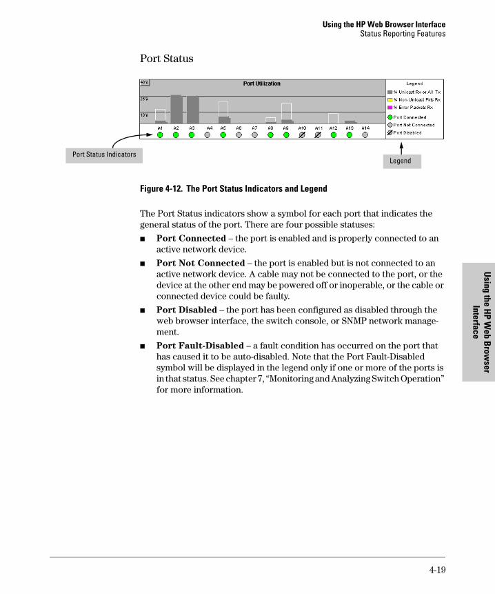
Using the HP Web Browser InterfaceStatus Reporting Features
Using the H
P Web B
rowser
Interface
Port Status
Figure 4-12. The Port Status Indicators and Legend
The Port Status indicators show a symbol for each port that indicates the general status of the port. There are four possible statuses:
� Port Connected – the port is enabled and is properly connected to an active network device.
� Port Not Connected – the port is enabled but is not connected to an active network device. A cable may not be connected to the port, or the device at the other end may be powered off or inoperable, or the cable or connected device could be faulty.
� Port Disabled – the port has been configured as disabled through the web browser interface, the switch console, or SNMP network manage-ment.
� Port Fault-Disabled – a fault condition has occurred on the port that has caused it to be auto-disabled. Note that the Port Fault-Disabled symbol will be displayed in the legend only if one or more of the ports is in that status. See chapter 7, “Monitoring and Analyzing Switch Operation” for more information.
Port Status IndicatorsLegend
4-19
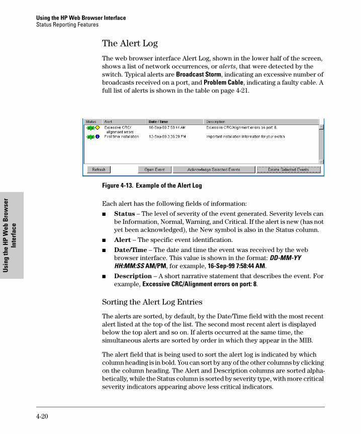
Using the HP Web Browser InterfaceStatus Reporting Features
Usin
g th
e H
P W
eb B
row
ser
Inte
rfac
e
The Alert Log
The web browser interface Alert Log, shown in the lower half of the screen, shows a list of network occurrences, or alerts, that were detected by the switch. Typical alerts are Broadcast Storm, indicating an excessive number of broadcasts received on a port, and Problem Cable, indicating a faulty cable. A full list of alerts is shown in the table on page 4-21.
Figure 4-13. Example of the Alert Log
Each alert has the following fields of information:
� Status – The level of severity of the event generated. Severity levels can be Information, Normal, Warning, and Critical. If the alert is new (has not yet been acknowledged), the New symbol is also in the Status column.
� Alert – The specific event identification.
� Date/Time – The date and time the event was received by the web browser interface. This value is shown in the format: DD-MM-YY HH:MM:SS AM/PM, for example, 16-Sep-99 7:58:44 AM.
� Description – A short narrative statement that describes the event. For example, Excessive CRC/Alignment errors on port: 8.
Sorting the Alert Log Entries
The alerts are sorted, by default, by the Date/Time field with the most recent alert listed at the top of the list. The second most recent alert is displayed below the top alert and so on. If alerts occurred at the same time, the simultaneous alerts are sorted by order in which they appear in the MIB.
The alert field that is being used to sort the alert log is indicated by which column heading is in bold. You can sort by any of the other columns by clicking on the column heading. The Alert and Description columns are sorted alpha-betically, while the Status column is sorted by severity type, with more critical severity indicators appearing above less critical indicators.
4-20
Using the HP Web Browser InterfaceStatus Reporting Features
Using the H
P Web B
rowser
Interface
Alert Types
The following table lists the types of alerts that can be generated.
Table 4-2. Alert Strings and Descriptions
Alert String Alert Description
First Time Install Important installation information for your switch.
Too many undersized/giant packets
A device connected to this port is transmitting packets shorter than 64 bytes or longer than 1518 bytes (longer than 1522 bytes if tagged), with valid CRCs (unlike runts, which have invalid CRCs).
Excessive jabbering A device connected to this port is incessantly transmitting packets (“jabbering”), detected as oversized packets with CRC errors.
Excessive CRC/alignment errors
A high percentage of data errors has been detected on this port. Possible causes include:• Faulty cabling or invalid topology.• Duplex mismatch (full-duplex configured on one end of the link, half-duplex configured on
the other)• A malfunctioning NIC, NIC driver, or transceiver
Excessive late collisions Late collisions (collisions detected after transmitting 64 bytes) have been detected on this port. Possible causes include:• An overextended LAN topology• Duplex mismatch (full-duplex configured on one end of the link, half-duplex configured on
the other)• A misconfigured or faulty device connected to the port
High collision or drop rate A large number of collisions or packet drops have occurred on the port. Possible causes include:• A extremely high level of traffic on the port• Duplex mismatch• A misconfigured or malfunctioning NIC or transceiver on a device connected to this port• A topology loop in the network
Excessive broadcasts An extremely high percentage of broadcasts was received on this port. This degrades the performance of all devices connected to the port. Possible causes include:• A network topology loop—this is the usual cause• A malfunctioning device, NIC, NIC driver, or software package
Loss of Link Lost connection to one or multiple devices on the port.
Loss of stack member The Commander has lost the connection to a stack member.
4-21
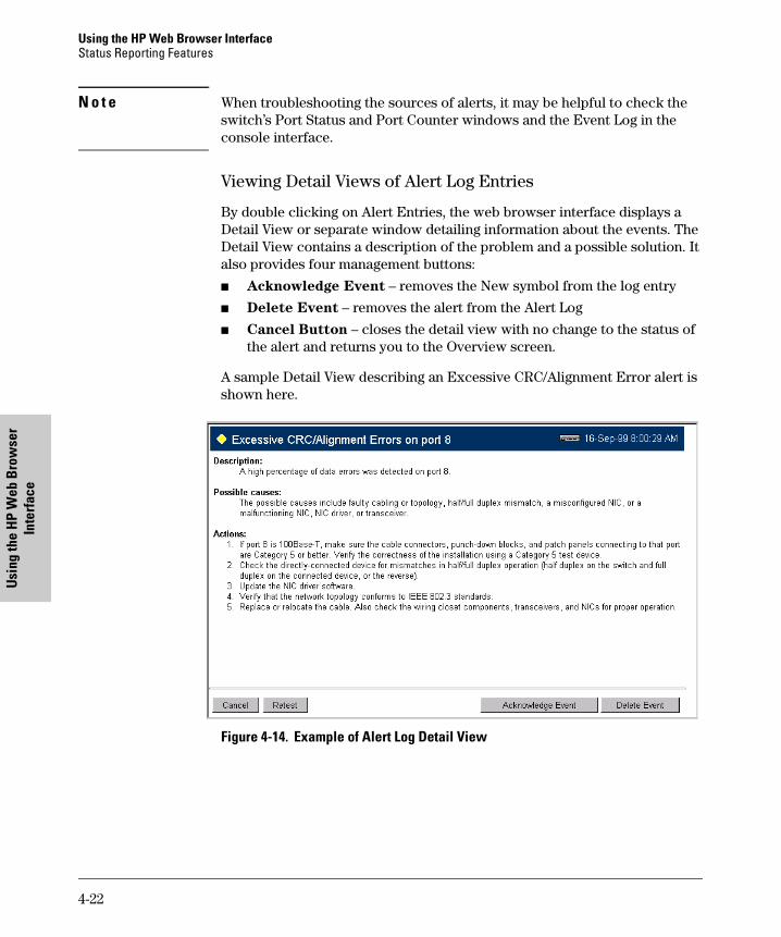
Using the HP Web Browser InterfaceStatus Reporting Features
Usin
g th
e H
P W
eb B
row
ser
Inte
rfac
e
N o t e When troubleshooting the sources of alerts, it may be helpful to check the switch’s Port Status and Port Counter windows and the Event Log in the console interface.
Viewing Detail Views of Alert Log Entries
By double clicking on Alert Entries, the web browser interface displays a Detail View or separate window detailing information about the events. The Detail View contains a description of the problem and a possible solution. It also provides four management buttons:
� Acknowledge Event – removes the New symbol from the log entry
� Delete Event – removes the alert from the Alert Log
� Cancel Button – closes the detail view with no change to the status of the alert and returns you to the Overview screen.
A sample Detail View describing an Excessive CRC/Alignment Error alert is shown here.
Figure 4-14. Example of Alert Log Detail View
4-22
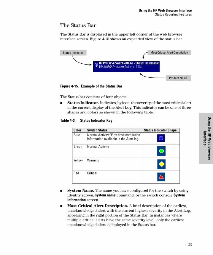
Using the HP Web Browser InterfaceStatus Reporting Features
Using the H
P Web B
rowser
Interface
The Status Bar
The Status Bar is displayed in the upper left corner of the web browser interface screen. Figure 4-15 shows an expanded view of the status bar.
Figure 4-15. Example of the Status Bar
The Status bar consists of four objects:
� Status Indicator. Indicates, by icon, the severity of the most critical alert in the current display of the Alert Log. This indicator can be one of three shapes and colors as shown in the following table.
Table 4-3. Status Indicator Key
� System Name. The name you have configured for the switch by using Identity screen, system name command, or the switch console System Information screen.
� Most Critical Alert Description. A brief description of the earliest, unacknowledged alert with the current highest severity in the Alert Log, appearing in the right portion of the Status Bar. In instances where multiple critical alerts have the same severity level, only the earliest unacknowledged alert is deployed in the Status bar.
Color Switch Status Status Indicator ShapeBlue Normal Activity; "First time installation"
information available in the Alert log.
Green Normal Activity
Yellow Warning
Red Critical
Status Indicator Most Critical Alert Description
Product Name
4-23
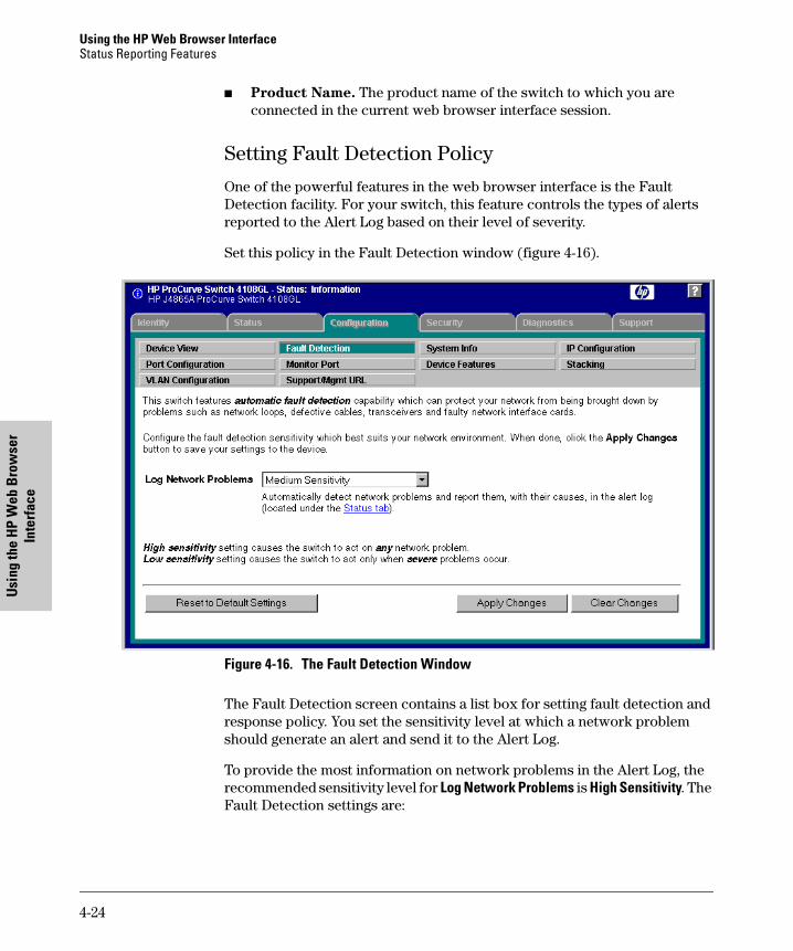
Using the HP Web Browser InterfaceStatus Reporting Features
Usin
g th
e H
P W
eb B
row
ser
Inte
rfac
e
� Product Name. The product name of the switch to which you are connected in the current web browser interface session.
Setting Fault Detection Policy
One of the powerful features in the web browser interface is the Fault Detection facility. For your switch, this feature controls the types of alerts reported to the Alert Log based on their level of severity.
Set this policy in the Fault Detection window (figure 4-16).
Figure 4-16. The Fault Detection Window
The Fault Detection screen contains a list box for setting fault detection and response policy. You set the sensitivity level at which a network problem should generate an alert and send it to the Alert Log.
To provide the most information on network problems in the Alert Log, the recommended sensitivity level for Log Network Problems is High Sensitivity. The Fault Detection settings are:
4-24

Using the HP Web Browser InterfaceStatus Reporting Features
Using the H
P Web B
rowser
Interface
� High Sensitivity. This policy directs the switch to send all alerts to the Alert Log. This setting is most effective on networks that have none or few problems.
� Medium Sensitivity. This policy directs the switch to send alerts related to network problems to the Alert Log. If you want to be notified of problems which cause a noticeable slowdown on the network, use this setting.
� Low Sensitivity. This policy directs the switch to send only the most severe alerts to the Alert Log. This policy is most effective on a network that normally has a lot of problems and you want to be informed of only the most severe ones.
� Never. Disables the Alert Log and transmission of alerts (traps) to the management server (in cases where a network management tool such as HP TopTools for Hubs & Switches is in use). Use this option when you don’t want to use the Alert Log.
The Fault Detection Window also contains three Change Control Buttons:
� Apply Changes. This button stores the settings you have selected for all future sessions with the web browser interface until you decide to change them.
� Clear Changes. This button removes your settings and returns the settings for the list box to the level it was at in the last saved detection-setting session.
� Reset to Default Settings. This button reverts the policy setting to Medium Sensitivity for Log Network Problems.
4-25

Using the HP Web Browser InterfaceStatus Reporting Features
Usin
g th
e H
P W
eb B
row
ser
Inte
rfac
e
4-26
Switch M
emory and
Configuration
5
Switch Memory and Configuration
Chapter Contents
Overview . . . . . . . . . . . . . . . . . . . . . . . . . . . . . . . . . . . . . . . . . . . . . . . . . . . . . . 5-2
Overview of Configuration File Management . . . . . . . . . . . . . . . . . . . . . . . . 5-2
Using the CLI To Implement Configuration Changes . . . . . . . . . . . . . . . . . 5-4
Using the Menu and Web Browser Interfaces To Implement Configuration Changes . . . . . . . . . . . . . . . . . . . . . . . . . . . . . . . . . . . . . . . . . . 5-7
Using the Menu Interface To Implement Configuration Changes . . . 5-8Using Save and Cancel in the Menu Interface . . . . . . . . . . . . . . . . 5-8Rebooting from the Menu Interface . . . . . . . . . . . . . . . . . . . . . . . . 5-9
Using the Web Browser Interface To Implement Configuration Changes . . . . . . . . . . . . . . . . . . . . . . . . . . . . . . . . . . . . . . 5-11
Using Primary and Secondary Flash Image Options . . . . . . . . . . . . . . . . . 5-11
Displaying the Current Flash Image Data . . . . . . . . . . . . . . . . . . . . . . 5-12
OS Downloads . . . . . . . . . . . . . . . . . . . . . . . . . . . . . . . . . . . . . . . . . . . . . 5-14
Local OS Replacement and Removal . . . . . . . . . . . . . . . . . . . . . . . . . . 5-15
Rebooting the Switch . . . . . . . . . . . . . . . . . . . . . . . . . . . . . . . . . . . . . . . 5-17
Operating Notes . . . . . . . . . . . . . . . . . . . . . . . . . . . . . . . . . . . . . . . . . . . . 5-19
5-1
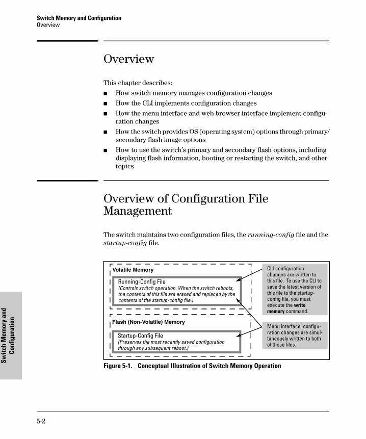
Switch Memory and ConfigurationOverview
Switc
h M
emor
y an
d Co
nfig
urat
ion
Overview
This chapter describes:
� How switch memory manages configuration changes
� How the CLI implements configuration changes
� How the menu interface and web browser interface implement configu-ration changes
� How the switch provides OS (operating system) options through primary/secondary flash image options
� How to use the switch’s primary and secondary flash options, including displaying flash information, booting or restarting the switch, and other topics
Overview of Configuration File Management
The switch maintains two configuration files, the running-config file and the startup-config file.
Figure 5-1. Conceptual Illustration of Switch Memory Operation
Running-Config File(Controls switch operation. When the switch reboots, the contents of this file are erased and replaced by the contents of the startup-config file.)
Startup-Config File(Preserves the most recently saved configuration through any subsequent reboot.)
Volatile Memory
Flash (Non-Volatile) Memory
CLI configuration changes are written to this file. To use the CLI to save the latest version of this file to the startup-config file, you must execute the write memory command.
Menu interface configu-ration changes are simul-taneously written to both of these files.
5-2
Switch Memory and ConfigurationOverview of Configuration File Management
Switch M
emory and
Configuration
� Running Config File: Exists in volatile memory and controls switch operation. If no configuration changes have been made in the CLI since the switch was last booted, the running-config file is identical to the startup-config file.
� Startup-config File: Exists in flash (non-volatile) memory and is used to preserve the most recently-saved configuration as the "permanent" configuration.
Rebooting the switch replaces the current running-config file with a new running-config file that is an exact copy of the current startup-config file.
N o t e Any of the following actions reboots the switch:
• Executing the boot or the reload command in the CLI
• Executing the Reboot command in the menu interface
• Pressing the Reset button on the front of the switch
• Removing, then restoring power to the switch
For more on reboots and the switch’s dual-flash images, see “Using Primary and Secondary Flash Image Options” on page 5-11.
Options for Saving a New Configuration. Making one or more changes to the running-config file creates a new operating configuration. Saving a new configuration means to overwrite (replace) the current startup-config file with the current running-config file. This means that if the switch subsequently reboots for any reason, it will resume operation using the new configuration instead of the configuration previously defined in the startup-config file. There are three ways to save a new configuration:
� In the CLI: Use the write memory command. This overwrites the current startup-config file with the contents of the current running-config file.
� In the menu interface: Use the Save command. This overwrites both the running-config file and the startup-config file with the changes you have specified in the menu interface screen.
� In the web browser interface: Use the [Apply Changes] button or other appropriate button. This overwrites both the running-config file and the startup-config file with the changes you have specified in the web browser interface window.
Note that using the CLI instead of the menu or web browser interface gives you the option of changing the running configuration without affecting the startup configuration. This allows you to test the change without making it
5-3
Switch Memory and ConfigurationUsing the CLI To Implement Configuration Changes
Switc
h M
emor
y an
d Co
nfig
urat
ion
"permanent". When you are satisfied that the change is satisfactory, you can make it permanent by executing the write memory command. For example, suppose you use the following command to disable port 5:
HP4108(config)# interface ethernet 5 disable
The above command disables port 5 in the running-config file, but not in the startup-config file. Port 5 remains disabled only until the switch reboots. If you want port 5 to remain disabled through the next reboot, use write memory to save the current running-config file to the startup-config file in flash memory.
HP4108(config)# write memory
Storing and Retrieving Configuration Files. You can store or retrieve a backup copy of the startup-config file on another device. For more informa-tion, see appendix A, "Transferring an Operating System or Startup-Config File"
Using the CLI To Implement Configuration Changes
The CLI offers these capabilities:
� Access to the full set of switch configuration features
� The option of testing configuration changes before making them perma-nent
How To Use the CLI To View the Current Configuration Files. Use show commands to view the configuration for individual features, such as port status or Spanning Tree Protocol. However, to view either the entire startup-config file or the entire running-config file, use the following commands:
� show startup-config: Displays the current startup-config file.
� write terminal: Displays the current running-config file.
N o t e The show startup-config and write terminal commands display the configuration settings that differ from the switch’s factory-default configuration.
5-4
Switch Memory and ConfigurationUsing the CLI To Implement Configuration Changes
Switch M
emory and
Configuration
How To Use the CLI To Reconfigure Switch Features. Use this proce-dure to permanently change the switch configuration (that is, to enter a change in the startup-config file).
1. Use the appropriate CLI commands to reconfigure the desired switch parameters. This updates the selected parameters in the running-config file.
2. Use the appropriate show commands to verify that you have correctly made the desired changes.
3. Observe the switch’s performance with the new parameter settings to verify the effect of your changes.
4. When you are satisfied that you have the correct parameter settings, use the write memory command to copy the changes to the startup-config file.
Syntax: write memory
For example, the default port mode setting is auto. Suppose that your network uses Cat 3 wiring and you want to connect the switch to another autosensing device capable of 100 Mbps operation. Because 100 Mbps over Cat 3 wiring can introduce transmission problems, the recommended port mode is auto-10, which allows the port to negotiate full- or half-duplex, but restricts speed to 10 Mbps. The following command configures port 5 to auto-10 mode in the running-config file, allowing you to observe performance on the link without making the mode change permanent.
HP4108(config)# interface e 5 speed-duplex auto-10
After you are satisfied that the link is operating properly, you can save the change to the switch’s permanent configuration (the startup-config file) by executing the following command:
HP4108(config)# write memory
The new mode (auto-10) on port 5 is now saved in the startup-config file, and the startup-config and running-config files are identical. If you subsequently reboot the switch, the auto-10 mode configuration on port 5 will remain because it is included in the startup-config file.
How To Cancel Changes You Have Made to the Running-Config File.
If you use the CLI to change parameter settings in the running-config file, and then decide that you don’t want those changes to remain, you can use either of the following methods to remove them:
5-5
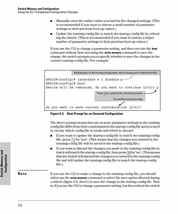
Switch Memory and ConfigurationUsing the CLI To Implement Configuration Changes
Switc
h M
emor
y an
d Co
nfig
urat
ion
� Manually enter the earlier values you had for the changed settings. (This is recommended if you want to restore a small number of parameter settings to their previous boot-up values.)
� Update the running-config file to match the startup-config file by reboot-ing the switch. (This is recommended if you want to restore a larger number of parameter settings to their previous boot-up values.)
If you use the CLI to change a parameter setting, and then execute the boot command without first executing the write memory command to save the change, the switch prompts you to specify whether to save the changes in the current running-config file. For example:
Figure 5-2. Boot Prompt for an Unsaved Configuration
The above prompt means that one or more parameter settings in the running-config file differ from their counterparts in the startup-config file and you need to choose which config file to retain and which to discard.
� If you want to update the startup-config file to match the running-config file, press [Y] for "yes". (This means that the changes you entered in the running-config file will be saved in the startup-config file.)
� If you want to discard the changes you made to the running-config file so that it will match the startup-config file, then press [N] for "no". (This means that the switch will discard the changes you entered in the running-config file and will update the running-config file to match the startup-config file.)
N o t e If you use the CLI to make a change to the running-config file, you should either use the write memory command or select the save option allowed during a reboot (figure 5-2, above) to save the change to the startup-config file. That is, if you use the CLI to change a parameter setting, but then reboot the switch
HP4108(config)# interface e 1 disable
HP4108(config)# boot
Device will be rebooted, do you want to continue [y/n]? y
Do you want to save current configuration [y/n]?
Press [Y] to continue the rebooting process.
You will then see this prompt.
Disables port 1 in the running configuration, which causes port 1 to block all traffic.
5-6
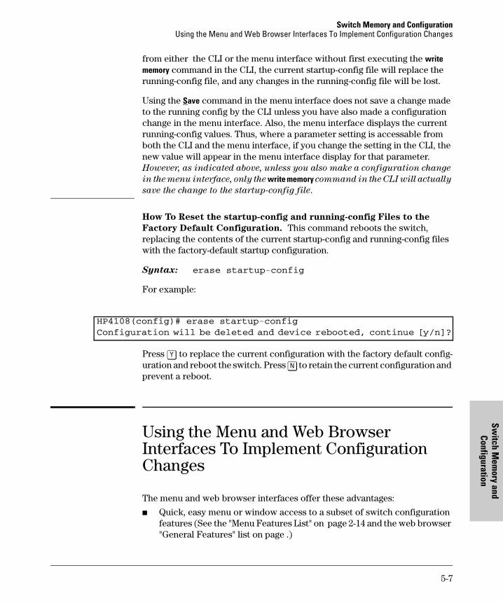
Switch Memory and ConfigurationUsing the Menu and Web Browser Interfaces To Implement Configuration Changes
Switch M
emory and
Configuration
from either the CLI or the menu interface without first executing the write memory command in the CLI, the current startup-config file will replace the running-config file, and any changes in the running-config file will be lost.
Using the Save command in the menu interface does not save a change made to the running config by the CLI unless you have also made a configuration change in the menu interface. Also, the menu interface displays the current running-config values. Thus, where a parameter setting is accessable from both the CLI and the menu interface, if you change the setting in the CLI, the new value will appear in the menu interface display for that parameter. However, as indicated above, unless you also make a configuration change
in the menu interface, only the write memory command in the CLI will actually
save the change to the startup-config file.
How To Reset the startup-config and running-config Files to the
Factory Default Configuration. This command reboots the switch, replacing the contents of the current startup-config and running-config files with the factory-default startup configuration.
Syntax: erase startup-config
For example:
Press [Y] to replace the current configuration with the factory default config-uration and reboot the switch. Press [N] to retain the current configuration and prevent a reboot.
Using the Menu and Web Browser Interfaces To Implement Configuration Changes
The menu and web browser interfaces offer these advantages:
� Quick, easy menu or window access to a subset of switch configuration features (See the "Menu Features List" on page 2-14 and the web browser "General Features" list on page .)
HP4108(config)# erase startup-config
Configuration will be deleted and device rebooted, continue [y/n]?
5-7
Switch Memory and ConfigurationUsing the Menu and Web Browser Interfaces To Implement Configuration Changes
Switc
h M
emor
y an
d Co
nfig
urat
ion
� Viewing several related configuration parameters in the same screen, with their default and current settings
� Immediately changing both the running-config file and the startup-config file with a single command
Using the Menu Interface To Implement Configuration Changes
You can use the menu interface to simultaneously save and implement a subset of switch configuration changes without having to reboot the switch. That is, when you save a configuration change in the menu interface, you simulta-neously change both the running-config file and the startup-config file.
N o t e The only exception to this operation are two VLAN-related parameter changes that require a reboot—described under "Rebooting To Activate Configuration Changes" on page 5-10.
Using Save and Cancel in the Menu Interface
For any configuration screen in the menu interface, the Save command:
1. Implements the changes in the running-config file
2. Saves your changes to the startup-config file
If you decide not to save and implement the changes in the screen, select Cancel to discard them and continue switch operation with the curent opera-tion. For example, suppose you have made the changes shown below in the System Information screen:
5-8
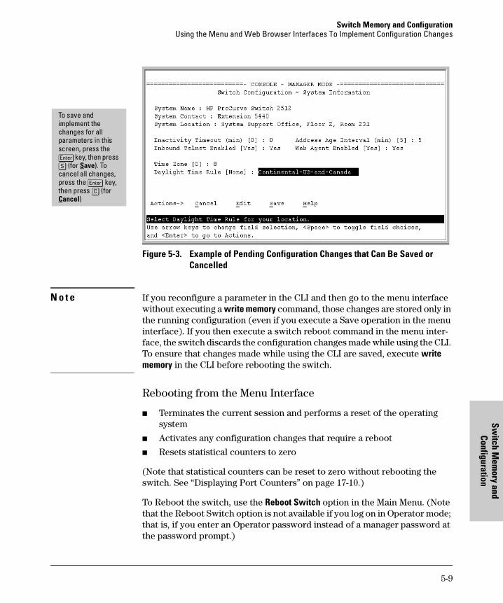
Switch Memory and ConfigurationUsing the Menu and Web Browser Interfaces To Implement Configuration Changes
Switch M
emory and
Configuration
Figure 5-3. Example of Pending Configuration Changes that Can Be Saved or Cancelled
N o t e If you reconfigure a parameter in the CLI and then go to the menu interface without executing a write memory command, those changes are stored only in the running configuration (even if you execute a Save operation in the menu interface). If you then execute a switch reboot command in the menu inter-face, the switch discards the configuration changes made while using the CLI. To ensure that changes made while using the CLI are saved, execute write memory in the CLI before rebooting the switch.
Rebooting from the Menu Interface
� Terminates the current session and performs a reset of the operating system
� Activates any configuration changes that require a reboot
� Resets statistical counters to zero
(Note that statistical counters can be reset to zero without rebooting the switch. See “Displaying Port Counters” on page 17-10.)
To Reboot the switch, use the Reboot Switch option in the Main Menu. (Note that the Reboot Switch option is not available if you log on in Operator mode; that is, if you enter an Operator password instead of a manager password at the password prompt.)
To save and implement the changes for all parameters in this screen, press the [Enter] key, then press [S] (for Save). To cancel all changes, press the [Enter] key, then press [C] (for Cancel)
5-9
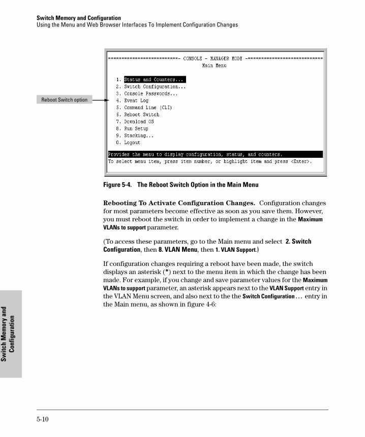
Switch Memory and ConfigurationUsing the Menu and Web Browser Interfaces To Implement Configuration Changes
Switc
h M
emor
y an
d Co
nfig
urat
ion
Figure 5-4. The Reboot Switch Option in the Main Menu
Rebooting To Activate Configuration Changes. Configuration changes for most parameters become effective as soon as you save them. However, you must reboot the switch in order to implement a change in the Maximum VLANs to support parameter.
(To access these parameters, go to the Main menu and select 2. Switch Configuration, then 8. VLAN Menu, then 1. VLAN Support.)
If configuration changes requiring a reboot have been made, the switch displays an asterisk (*) next to the menu item in which the change has been made. For example, if you change and save parameter values for the Maximum VLANs to support parameter, an asterisk appears next to the VLAN Support entry in the VLAN Menu screen, and also next to the the Switch Configuration . . . entry in the Main menu, as shown in figure 4-6:
Reboot Switch option
5-10
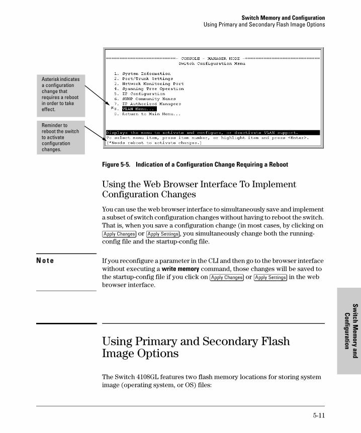
Switch Memory and ConfigurationUsing Primary and Secondary Flash Image Options
Switch M
emory and
Configuration
Figure 5-5. Indication of a Configuration Change Requiring a Reboot
Using the Web Browser Interface To Implement Configuration Changes
You can use the web browser interface to simultaneously save and implement a subset of switch configuration changes without having to reboot the switch. That is, when you save a configuration change (in most cases, by clicking on [Apply Changes] or [Apply Settings], you simultaneously change both the running-config file and the startup-config file.
N o t e If you reconfigure a parameter in the CLI and then go to the browser interface without executing a write memory command, those changes will be saved to the startup-config file if you click on [Apply Changes] or [Apply Settings] in the web browser interface.
Using Primary and Secondary Flash Image Options
The Switch 4108GL features two flash memory locations for storing system image (operating system, or OS) files:
Reminder to reboot the switch to activate configuration changes.
Asterisk indicates a configuration change that requires a reboot in order to take effect.
5-11
Switch Memory and ConfigurationUsing Primary and Secondary Flash Image Options
Switc
h M
emor
y an
d Co
nfig
urat
ion
� Primary Flash: The default storage for OS (system image) files.
� Secondary Flash: The additional storage for either a redundant or an alternate OS (system image) file.
With the Primary/Secondary flash option you can test a new image in your system without having to replace a previously existing image. You can also use the image options for troubleshooting. For example, you can copy a problem image into Secondary flash for later analysis and place another, proven image in Primary flash to run your system. The switch can use only one image at a time.
The following tasks involve primary/secondary flash options:
� Displaying the current flash image data and determining which OS ver-sions are available
� OS downloads
� Local OS replacement, and removal (erasing)
� System booting
Displaying the Current Flash Image Data
Use the commands in this section to:
� Determine whether there are flash images in both primary and secondary flash
� Determine whether the images in primary and secondary flash are the same
� Identify which OS version is currently running
Viewing the Currently Active Flash Image Version. This command identifies the software version on which the switch is currently running, and whether the active version was booted from the primary or secondary flash image.
Syntax: show version
For example, if the switch is using an OS version of G.01.01 stored in Primary flash, show version produces the following:
5-12
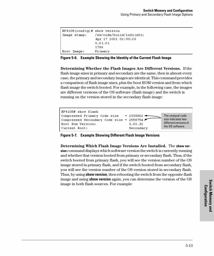
Switch Memory and ConfigurationUsing Primary and Secondary Flash Image Options
Switch M
emory and
Configuration
Figure 5-6. Example Showing the Identity of the Current Flash Image
Determining Whether the Flash Images Are Different Versions. If the flash image sizes in primary and secondary are the same, then in almost every case, the primary and secondary images are identical. This command provides a comparison of flash image sizes, plus the boot ROM version and from which flash image the switch booted. For example, in the following case, the images are different versions of the OS software (flash image) and the switch is running on the version stored in the secondary flash image:
Figure 5-7. Example Showing Different Flash Image Versions
Determining Which Flash Image Versions Are Installed. The show ver-sion command displays which software version the switch is currently running and whether that version booted from primary or secondary flash. Thus, if the switch booted from primary flash, you will see the version number of the OS image stored in primary flash, and if the switch booted from secondary flash, you will see the version number of the OS version stored in secondary flash. Thus, by using show version, then rebooting the switch from the opposite flash image and using show version again, you can determine the version of the OS image in both flash sources. For example:
The unequal code size indicates two different versions of the OS software.
5-13
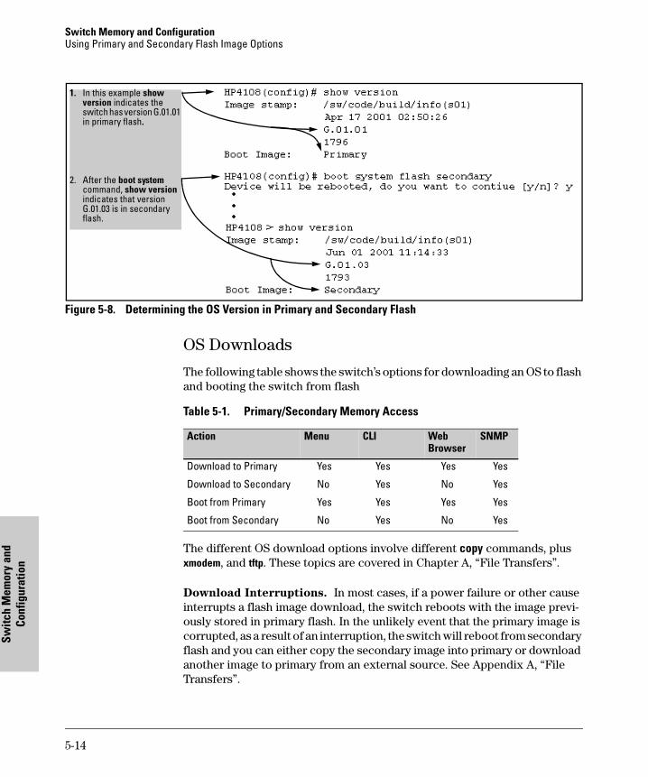
Switch Memory and ConfigurationUsing Primary and Secondary Flash Image Options
Switc
h M
emor
y an
d Co
nfig
urat
ion
Figure 5-8. Determining the OS Version in Primary and Secondary Flash
OS Downloads
The following table shows the switch’s options for downloading an OS to flash and booting the switch from flash
Table 5-1. Primary/Secondary Memory Access
The different OS download options involve different copy commands, plus xmodem, and tftp. These topics are covered in Chapter A, “File Transfers”.
Download Interruptions. In most cases, if a power failure or other cause interrupts a flash image download, the switch reboots with the image previ-ously stored in primary flash. In the unlikely event that the primary image is corrupted, as a result of an interruption, the switch will reboot from secondary flash and you can either copy the secondary image into primary or download another image to primary from an external source. See Appendix A, “File Transfers”.
1. In this example show version indicates the switch has version G.01.01 in primary flash.
2. After the boot system command, show version indicates that version G.01.03 is in secondary flash.
Action Menu CLI Web Browser
SNMP
Download to Primary Yes Yes Yes Yes
Download to Secondary No Yes No Yes
Boot from Primary Yes Yes Yes Yes
Boot from Secondary No Yes No Yes
5-14
Switch Memory and ConfigurationUsing Primary and Secondary Flash Image Options
Switch M
emory and
Configuration
Local OS Replacement and Removal
This section describes commands for erasing an OS (flash image) and copying an existing OS between primary and secondary flash.
N o t e It is not necessary to erase the content of a flash location before downloading another OS file. The process automatically overwrites the previous file with the new file. If you want to remove an unwanted OS version from flash, HP recommends that you do so by overwriting it with the same OS version that you are using to operate the switch, or with another acceptable OS version. To copy an OS image file between the primary and secondary flash locations, see “Copying an OS Image from One Flash Location to Another” , below.
The local commands described here are for flash image management within the switch. To download an OS image file from an external source, see Appendix A, “File Transfers”.
Copying an OS Image from One Flash Location to Another. When you copy the flash image from primary to secondary or the reverse, the switch overwrites the file in the destination location with a copy of the file from the source location. This means you do not have to erase the current image at the destination location before copying in a new image.
C a u t i o n Verify that there is an acceptable OS image in the source flash location from which you are going to copy. Use the show flash command or, if necessary, the procedure under “Determining Which Flash Image Versions Are Installed” on page 5-13 to verify an acceptable OS image. Attempting to copy from a source image location that has a corrupted flash image overwrites the image in the destination flash location. In this case, the switch will not have a valid flash image in either flash location, but will continue running on a temporary flash image in RAM. Do not reboot the switch. Instead, immediately download another valid flash image to primary or secondary flash. Otherwise, if the switch is rebooted without an OS image in either primary or secondary flash, the temporary flash image in RAM will be cleared and the switch will go down. To recover, see “Restoring a Flash Image” on page 18-25 (in the Troubleshoot-ing chapter).
Syntax: copy flash flash <destination flash>
where: destination flash = primary or secondary:
For example, to copy the image in secondary flash to primary flash:
5-15
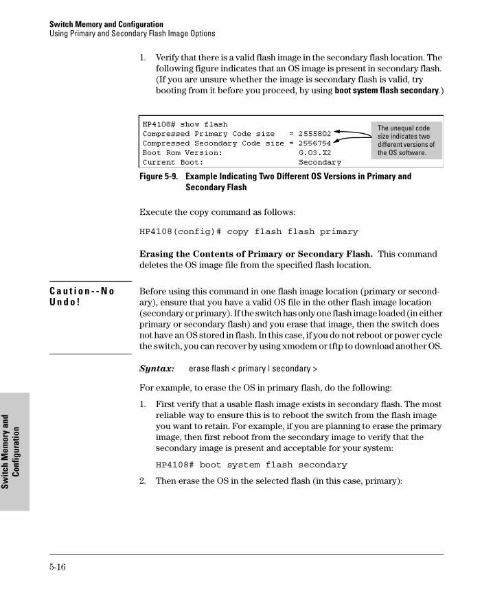
Switch Memory and ConfigurationUsing Primary and Secondary Flash Image Options
Switc
h M
emor
y an
d Co
nfig
urat
ion
1. Verify that there is a valid flash image in the secondary flash location. The following figure indicates that an OS image is present in secondary flash. (If you are unsure whether the image is secondary flash is valid, try booting from it before you proceed, by using boot system flash secondary.)
Figure 5-9. Example Indicating Two Different OS Versions in Primary and Secondary Flash
Execute the copy command as follows:
HP4108(config)# copy flash flash primary
Erasing the Contents of Primary or Secondary Flash. This command deletes the OS image file from the specified flash location.
C a u t i o n - - N o U n d o !
Before using this command in one flash image location (primary or second-ary), ensure that you have a valid OS file in the other flash image location (secondary or primary). If the switch has only one flash image loaded (in either primary or secondary flash) and you erase that image, then the switch does not have an OS stored in flash. In this case, if you do not reboot or power cycle the switch, you can recover by using xmodem or tftp to download another OS.
Syntax: erase flash < primary | secondary >
For example, to erase the OS in primary flash, do the following:
1. First verify that a usable flash image exists in secondary flash. The most reliable way to ensure this is to reboot the switch from the flash image you want to retain. For example, if you are planning to erase the primary image, then first reboot from the secondary image to verify that the secondary image is present and acceptable for your system:
HP4108# boot system flash secondary
2. Then erase the OS in the selected flash (in this case, primary):
The unequal code size indicates two different versions of the OS software.
5-16
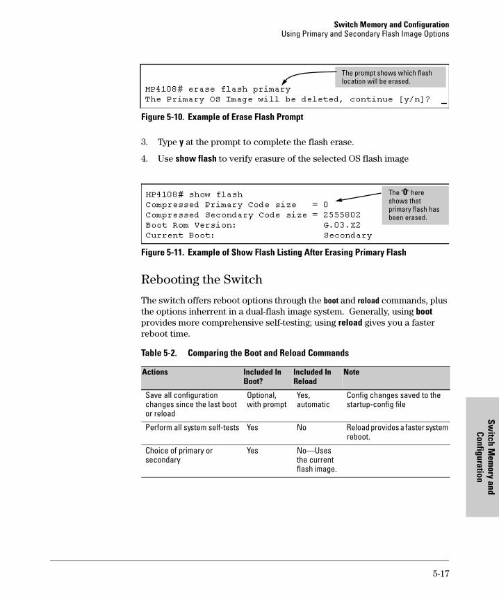
Switch Memory and ConfigurationUsing Primary and Secondary Flash Image Options
Switch M
emory and
Configuration
Figure 5-10. Example of Erase Flash Prompt
3. Type y at the prompt to complete the flash erase.
4. Use show flash to verify erasure of the selected OS flash image
Figure 5-11. Example of Show Flash Listing After Erasing Primary Flash
Rebooting the Switch
The switch offers reboot options through the boot and reload commands, plus the options inherrent in a dual-flash image system. Generally, using boot provides more comprehensive self-testing; using reload gives you a faster reboot time.
Table 5-2. Comparing the Boot and Reload Commands
The prompt shows which flash location will be erased.
Actions Included In Boot?
Included In Reload
Note
Save all configuration changes since the last boot or reload
Optional, with prompt
Yes, automatic
Config changes saved to the startup-config file
Perform all system self-tests Yes No Reload provides a faster system reboot.
Choice of primary or secondary
Yes No—Uses the current flash image.
The "0" here shows that primary flash has been erased.
5-17
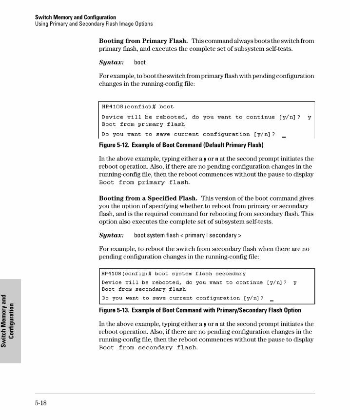
Switch Memory and ConfigurationUsing Primary and Secondary Flash Image Options
Switc
h M
emor
y an
d Co
nfig
urat
ion
Booting from Primary Flash. This command always boots the switch from primary flash, and executes the complete set of subsystem self-tests.
Syntax: boot
For example, to boot the switch from primary flash with pending configuration changes in the running-config file:
Figure 5-12. Example of Boot Command (Default Primary Flash)
In the above example, typing either a y or n at the second prompt initiates the reboot operation. Also, if there are no pending configuration changes in the running-config file, then the reboot commences without the pause to display Boot from primary flash.
Booting from a Specified Flash. This version of the boot command gives you the option of specifying whether to reboot from primary or secondary flash, and is the required command for rebooting from secondary flash. This option also executes the complete set of subsystem self-tests.
Syntax: boot system flash < primary | secondary >
For example, to reboot the switch from secondary flash when there are no pending configuration changes in the running-config file:
Figure 5-13. Example of Boot Command with Primary/Secondary Flash Option
In the above example, typing either a y or n at the second prompt initiates the reboot operation. Also, if there are no pending configuration changes in the running-config file, then the reboot commences without the pause to display Boot from secondary flash.
5-18
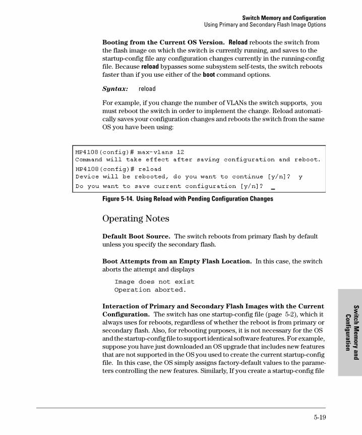
Switch Memory and ConfigurationUsing Primary and Secondary Flash Image Options
Switch M
emory and
Configuration
Booting from the Current OS Version. Reload reboots the switch from the flash image on which the switch is currently running, and saves to the startup-config file any configuration changes currently in the running-config file. Because reload bypasses some subsystem self-tests, the switch reboots faster than if you use either of the boot command options.
Syntax: reload
For example, if you change the number of VLANs the switch supports, you must reboot the switch in order to implement the change. Reload automati-cally saves your configuration changes and reboots the switch from the same OS you have been using:
Figure 5-14. Using Reload with Pending Configuration Changes
Operating Notes
Default Boot Source. The switch reboots from primary flash by default unless you specify the secondary flash.
Boot Attempts from an Empty Flash Location. In this case, the switch aborts the attempt and displays
Image does not exist
Operation aborted.
Interaction of Primary and Secondary Flash Images with the Current
Configuration. The switch has one startup-config file (page 5-2), which it always uses for reboots, regardless of whether the reboot is from primary or secondary flash. Also, for rebooting purposes, it is not necessary for the OS and the startup-config file to support identical software features. For example, suppose you have just downloaded an OS upgrade that includes new features that are not supported in the OS you used to create the current startup-config file. In this case, the OS simply assigns factory-default values to the parame-ters controlling the new features. Similarly, If you create a startup-config file
5-19

Switch Memory and ConfigurationUsing Primary and Secondary Flash Image Options
Switc
h M
emor
y an
d Co
nfig
urat
ion
while using a version "Y" of the OS, and then reboot the switch with an earlier OS version "X" that does not include all of the features found in "Y", the OS simply ignores the parameters for any features that it does not support.
5-20
Interface Access
System Inform
ati
6
Interface Access and System Information
Chapter Contents
Overview . . . . . . . . . . . . . . . . . . . . . . . . . . . . . . . . . . . . . . . . . . . . . . . . . . . . . . 6-2
Interface Access: Console/Serial Link, Web, and Inbound Telnet . . . . . . . 6-3
Menu: Modifying the Interface Access . . . . . . . . . . . . . . . . . . . . . . . . . . 6-4
CLI: Modifying the Interface Access . . . . . . . . . . . . . . . . . . . . . . . . . . . . 6-5
System Information . . . . . . . . . . . . . . . . . . . . . . . . . . . . . . . . . . . . . . . . . . . . . 6-8
Menu: Viewing and Configuring System Information . . . . . . . . . . . . . . 6-9
CLI: Viewing and Configuring System Information . . . . . . . . . . . . . . 6-10
Web: Configuring System Parameters . . . . . . . . . . . . . . . . . . . . . . . . . 6-13
6-1
and on
Interface Access and System Information Overview
Inte
rfac
e A
cces
s an
d Sy
stem
Info
rmat
ion
Overview
This chapter describes how to view and modify the configuration for switch interface access and switch system information . For help on how to actually use the interfaces built into the switch, refer to:
� Chapter 2, “Using the Menu Interface”
� Chapter 3, “Using the Command Line Interface (CLI)”
� Chapter 4, Using the HP Web Browser Interface”
Why Configure Interface Access and System Information? The inter-face access features in the switch operate properly by default. However, you can modify or disable access features to suit your particular needs. Similarly, you can choose to leave the system information parameters at their default settings. However, modifying these parameters can help you to more easily manage a group of devices across your network.
6-2
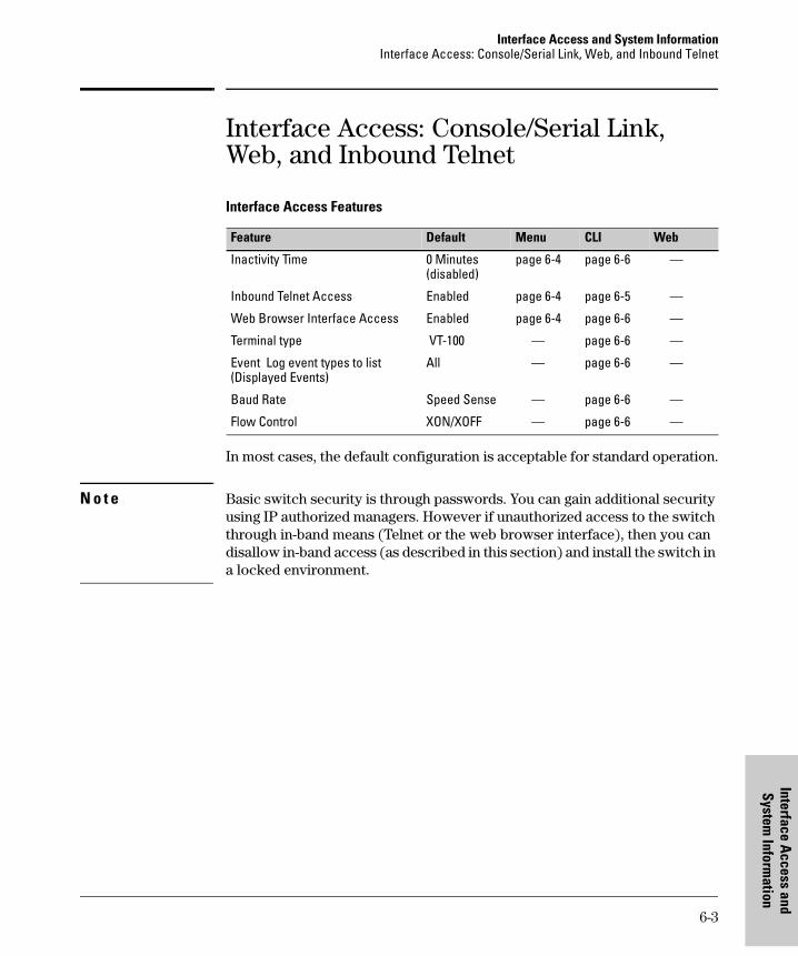
Interface Access and System InformationInterface Access: Console/Serial Link, Web, and Inbound Telnet
Interface Access
System Inform
ati
Interface Access: Console/Serial Link, Web, and Inbound Telnet
Interface Access Features
In most cases, the default configuration is acceptable for standard operation.
N o t e Basic switch security is through passwords. You can gain additional security using IP authorized managers. However if unauthorized access to the switch through in-band means (Telnet or the web browser interface), then you can disallow in-band access (as described in this section) and install the switch in a locked environment.
Feature Default Menu CLI Web
Inactivity Time 0 Minutes(disabled)
page 6-4 page 6-6 —
Inbound Telnet Access Enabled page 6-4 page 6-5 —
Web Browser Interface Access Enabled page 6-4 page 6-6 —
Terminal type VT-100 — page 6-6 —
Event Log event types to list(Displayed Events)
All — page 6-6 —
Baud Rate Speed Sense — page 6-6 —
Flow Control XON/XOFF — page 6-6 —
6-3
and on
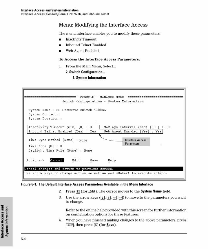
Interface Access and System Information Interface Access: Console/Serial Link, Web, and Inbound Telnet
Inte
rfac
e A
cces
s an
d Sy
stem
Info
rmat
ion
Menu: Modifying the Interface Access
The menu interface enables you to modify these parameters:
� Inactivity Timeout
� Inbound Telnet Enabled
� Web Agent Enabled
To Access the Interface Access Parameters:
1. From the Main Menu, Select...
2. Switch Configuration...1. System Information
Figure 6-1. The Default Interface Access Parameters Available in the Menu Interface
2. Press [E] (for Edit). The cursor moves to the System Name field.
3. Use the arrow keys ([v], [^], [<], [>]) to move to the parameters you want to change.
Refer to the online help provided with this screen for further information on configuration options for these features.
4. When you have finished making changes to the above parameters, press [Enter], then press [S] (for Save).
Interface Access Parameters
6-4
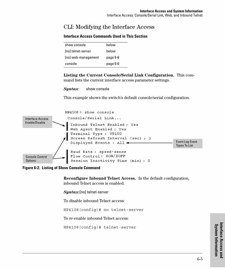
Interface Access and System InformationInterface Access: Console/Serial Link, Web, and Inbound Telnet
Interface Access
System Inform
ati
CLI: Modifying the Interface Access
Interface Access Commands Used in This Section
Listing the Current Console/Serial Link Configuration. This com-mand lists the current interface access parameter settings.
Syntax: show console
This example shows the switch’s default console/serial configuration.
Figure 6-2. Listing of Show Console Command
Reconfigure Inbound Telnet Access. In the default configuration, inbound Telnet access is enabled.
Syntax:[no] telnet-server
To disable inbound Telnet access:
HP4108(config)# no telnet-server
To re-enable inbound Telnet access:
HP4108(config)# telnet-server
show console below
[no] telnet-server below
[no] web-management page 6-6
console page 6-6
Interface Access Enable/Disable
Console Control Options
Event Log Event Types To List
6-5
and on
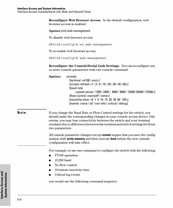
Interface Access and System Information Interface Access: Console/Serial Link, Web, and Inbound Telnet
Inte
rfac
e A
cces
s an
d Sy
stem
Info
rmat
ion
Reconfigure Web Browser Access. In the default configuration, web browser access is enabled.
Syntax:[no] web-management
To disable web browser access:
HP4108(config)# no web-management
To re-enable web browser access:
HP4108(config)# web-management
Reconfigure the Console/Serial Link Settings. You can reconfigure one or more console parameters with one console command.
Syntax: console [terminal <vt100 | ansi>] [screen-refresh <1 | 3 | 5 | 10 | 20 | 30 | 45 | 60>][baud-rate
<speed-sense | 1200 | 2400 | 4800 | 9600 | 19200 |38400 | 57600>][flow-control <xon/xoff | none>] [inactivity-timer <0 1 5 10 15 20 30 60 120>][events <none | all | non-info | critical | debug]
N o t e If you change the Baud Rate or Flow Control settings for the switch, you should make the corresponding changes in your console access device. Oth-erwise, you may lose connectivity between the switch and your terminal emulator due to differences between the terminal and switch settings for these two parameters.
All console parameter changes except events require that you save the config-uration with write memory and then execute boot before the new console configuration will take effect.
For example, to use one command to configure the switch with the following:
� VT100 operation
� 19,200 baud
� No flow control
� 10-minute inactivity time
� Critical log events
you would use the following command sequence:
6-6
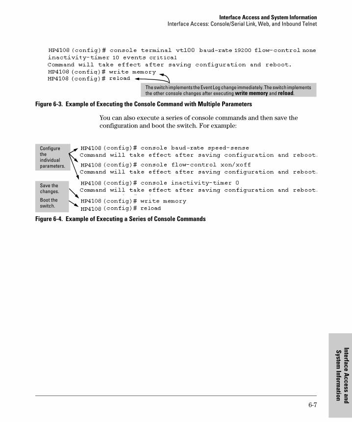
Interface Access and System InformationInterface Access: Console/Serial Link, Web, and Inbound Telnet
Interface Access
System Inform
ati
Figure 6-3. Example of Executing the Console Command with Multiple Parameters
You can also execute a series of console commands and then save the configuration and boot the switch. For example:
Figure 6-4. Example of Executing a Series of Console Commands
The switch implements the Event Log change immediately. The switch implements the other console changes after executing write memory and reload.
Configure the individual parameters.
Save the changes.
Boot the switch.
6-7
and on
Interface Access and System Information System Information
Inte
rfac
e A
cces
s an
d Sy
stem
Info
rmat
ion
System Information
System Information Features
Configuring system information is optional, but recommended.
System Name: Using a unique name helps you to identify individual devices in stacking environments and where you are using an SNMP network manage-ment tool such as HP TopTools for Hubs & Switches.
System Contact and Location: This information is helpful for identifying the person administratively responsible for the switch and for identifying the locations of individual switches.
MAC Age Interval: The number of seconds a MAC address the switch has learned remains in the switch’s address table before being aged out (deleted). Aging out occurs when there has been no traffic from the device belonging to that MAC address for the configured interval.
Time Sync Method: Selects the method (TimeP or SNTP) the switch will use for time synchronization. For more on this topic, refer to Chapter 8, “Time Protocols”.
Feature Default Menu CLI Web
System Name switch product name
page 6-9
page 6-11
page 6-13
System Contact n/a page 6-9
page 6-11
page 6-13
System Location n/a page 6-9
page 6-11
page 6-13
MAC Age Interval 300 seconds page 6-9
page 6-12
—
Time Sync Method None See Chapter 8, “Time Protocols”.
Time Zone 0 page 6-9
page 6-12
—
Daylight Time Rule None page 6-9
page 6-12
—
Time January 1, 1990 at 00:00:00 at last power reset
— page 6-12
—
6-8
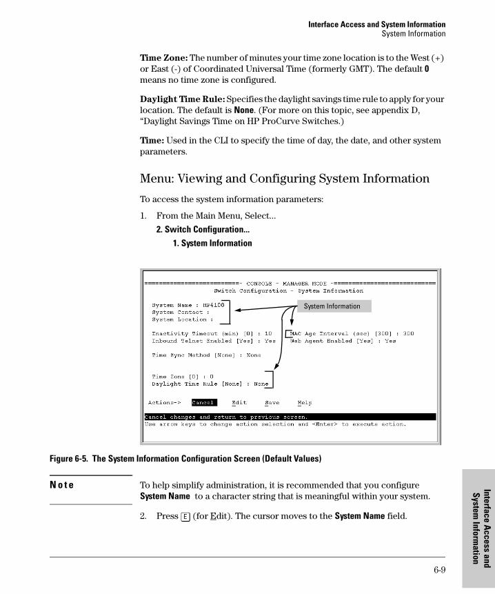
Interface Access and System InformationSystem Information
Interface Access
System Inform
ati
Time Zone: The number of minutes your time zone location is to the West (+) or East (-) of Coordinated Universal Time (formerly GMT). The default 0 means no time zone is configured.
Daylight Time Rule: Specifies the daylight savings time rule to apply for your location. The default is None. (For more on this topic, see appendix D, “Daylight Savings Time on HP ProCurve Switches.)
Time: Used in the CLI to specify the time of day, the date, and other system parameters.
Menu: Viewing and Configuring System Information
To access the system information parameters:
1. From the Main Menu, Select...
2. Switch Configuration...1. System Information
Figure 6-5. The System Information Configuration Screen (Default Values)
N o t e To help simplify administration, it is recommended that you configure System Name to a character string that is meaningful within your system.
2. Press [E] (for Edit). The cursor moves to the System Name field.
System Information
6-9
and on
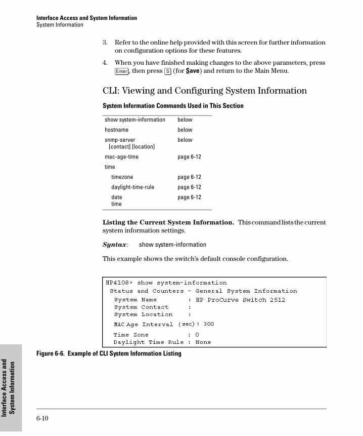
Interface Access and System Information System Information
Inte
rfac
e A
cces
s an
d Sy
stem
Info
rmat
ion
3. Refer to the online help provided with this screen for further information on configuration options for these features.
4. When you have finished making changes to the above parameters, press [Enter], then press [S] (for Save) and return to the Main Menu.
CLI: Viewing and Configuring System Information
System Information Commands Used in This Section
Listing the Current System Information. This command lists the current system information settings.
Syntax: show system-information
This example shows the switch’s default console configuration.
Figure 6-6. Example of CLI System Information Listing
show system-information below
hostname below
snmp-server [contact] [location]
below
mac-age-time page 6-12
time
timezone page 6-12
daylight-time-rule page 6-12
date time
page 6-12
6-10
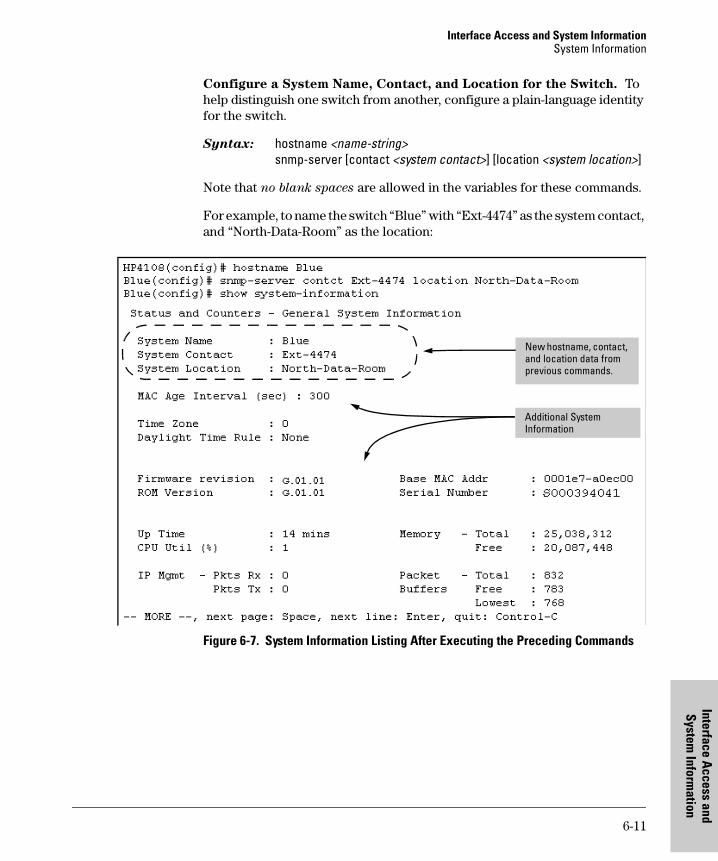
Interface Access and System InformationSystem Information
Interface Access
System Inform
ati
Configure a System Name, Contact, and Location for the Switch. To help distinguish one switch from another, configure a plain-language identity for the switch.
Syntax: hostname <name-string>snmp-server [contact <system contact>] [location <system location>]
Note that no blank spaces are allowed in the variables for these commands.
For example, to name the switch “Blue” with “Ext-4474” as the system contact, and “North-Data-Room” as the location:
Figure 6-7. System Information Listing After Executing the Preceding Commands
New hostname, contact, and location data from previous commands.
Additional System Information
6-11
and on
Interface Access and System Information System Information
Inte
rfac
e A
cces
s an
d Sy
stem
Info
rmat
ion
Reconfigure the Age Interval for Learned MAC Addresses. This com-mand corresponds to the MAC Age Interval in the menu interface, and is expressed in seconds.
Syntax: mac-age-time <10 . . 1000000> (seconds)
For example, to configure the age interval to seven minutes:
HP4108(config)# mac-age-time 420
Configure the Time Zone and Daylight Time Rule. These commands:
� Set the time zone you want to use
� Define the daylight time rule for keeping the correct time when daylight-saving-time shifts occur.
Syntax: time timezone <-720 . . 840>time daylight-time-rule <none | alaska | continental-us-and-canada |middle-europe-and-portugal | southern-hemisphere | western-europe |user-defined>
For example, this command configures the time zone and daylight time rule for Vancouver, British Columbia in Canada (time zone 8 = 480 minutes):
HP4108(config)# time timezone 480 daylight-time-rule
continental-us-and-canada
Configure the Time and Date. The switch uses the time command to con-figure both the time of day and the date. Also, executing time without param-eters lists the switch’s time of day and date. Note that the CLI uses a 24-hour clock scheme; that is, hour (hh) values from 1 p.m. to midnight are input as 13 - 24, respectively.
Syntax: time [hh:mm[:ss]] [mm/dd/ [yy]yy]
For example, to set the switch to 9:45 a.m. on November 11, 2001:
HP4108(config)# time 9:45 11/11/01
N o t e Executing reload or boot resets the time and date to their default startup values.
6-12
Interface Access and System InformationSystem Information
Interface Access
System Inform
ati
Web: Configuring System Parameters
In the web browser interface, you can enter the following system information:
� System Name
� System Location
� System Contact
For access to the MAC Age Interval and the Time parameters, use the menu interface or the CLI.
Configure System Parameters in the Web Browser Interface.
1. Click on the Configuration tab.
2. Click on [System Info].
3. Enter the data you want in the displayed fields.
4. Implement your new data by clicking on [Apply Changes].
To access the web-based help provided for the switch, click on [?] in the web browser screen.
6-13
and on

Interface Access and System Information System Information
Inte
rfac
e A
cces
s an
d Sy
stem
Info
rmat
ion
6-14
Configuring IP Addressing
7
Configuring IP Addressing
Contents
Overview . . . . . . . . . . . . . . . . . . . . . . . . . . . . . . . . . . . . . . . . . . . . . . . . . . . . . . 7-2
IP Configuration . . . . . . . . . . . . . . . . . . . . . . . . . . . . . . . . . . . . . . . . . . . . . . . . 7-3
Just Want a Quick Start? . . . . . . . . . . . . . . . . . . . . . . . . . . . . . . . . . . . . . 7-4
IP Addressing with Multiple VLANs . . . . . . . . . . . . . . . . . . . . . . . . . . . . 7-4
IP Addressing in a Stacking Environment . . . . . . . . . . . . . . . . . . . . . . . 7-5
Menu: Configuring IP Address, Gateway, and Time-To-Live (TTL) . . 7-5
CLI: Configuring IP Address, Gateway, Time-To-Live (TTL),and Timep . . . . . . . . . . . . . . . . . . . . . . . . . . . . . . . . . . . . . . . . . . . . . . . . . . 7-7
Web: Configuring IP Addressing . . . . . . . . . . . . . . . . . . . . . . . . . . . . . . . 7-9
How IP Addressing Affects Switch Operation . . . . . . . . . . . . . . . . . . . . 7-9DHCP/Bootp Operation . . . . . . . . . . . . . . . . . . . . . . . . . . . . . . . . . . 7-10Network Preparations for Configuring DHCP/Bootp . . . . . . . . . 7-13
Globally Assigned IP Network Addresses . . . . . . . . . . . . . . . . . . . . . . 7-14
7-1
Configuring IP Addressing Overview
Conf
igur
ing
IP A
ddre
ssin
g
Overview
This chapter describes the switch configuration features available in the menu interface, CLI and web browser interface. For help on how to use these interfaces, refer to:
� Chapter 2, “Using the Menu Interface”
� Chapter 3, “Using the Command Line Interface (CLI)”
� Chapter 4, Using the HP Web Browser Interface”
Why Configure IP Addressing? In its factory default configuration, the switch operates as a multiport learning bridge with network connectivity provided by the ports on the switch. However, to enable specific management access and control through your network, you will need IP addressing. (See table 7-1 on page 7-10.)
7-2
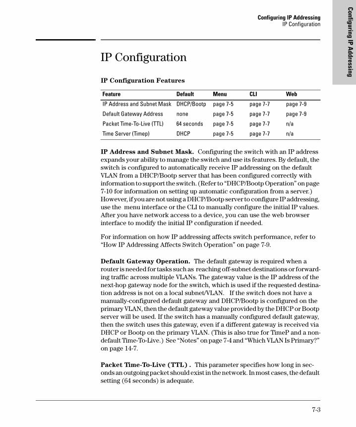
Configuring IP AddressingIP Configuration
Configuring IP Addressing
IP Configuration
IP Configuration Features
IP Address and Subnet Mask. Configuring the switch with an IP address expands your ability to manage the switch and use its features. By default, the switch is configured to automatically receive IP addressing on the default VLAN from a DHCP/Bootp server that has been configured correctly with information to support the switch. (Refer to “DHCP/Bootp Operation” on page 7-10 for information on setting up automatic configuration from a server.) However, if you are not using a DHCP/Bootp server to configure IP addressing, use the menu interface or the CLI to manually configure the initial IP values. After you have network access to a device, you can use the web browser interface to modify the initial IP configuration if needed.
For information on how IP addressing affects switch performance, refer to “How IP Addressing Affects Switch Operation” on page 7-9.
Default Gateway Operation. The default gateway is required when a router is needed for tasks such as reaching off-subnet destinations or forward-ing traffic across multiple VLANs. The gateway value is the IP address of the next-hop gateway node for the switch, which is used if the requested destina-tion address is not on a local subnet/VLAN. If the switch does not have a manually-configured default gateway and DHCP/Bootp is configured on the primary VLAN, then the default gateway value provided by the DHCP or Bootp server will be used. If the switch has a manually configured default gateway, then the switch uses this gateway, even if a different gateway is received via DHCP or Bootp on the primary VLAN. (This is also true for TimeP and a non-default Time-To-Live.) See “Notes” on page 7-4 and “Which VLAN Is Primary?” on page 14-7.
Packet Time-To-Live (TTL) . This parameter specifies how long in sec-onds an outgoing packet should exist in the network. In most cases, the default setting (64 seconds) is adequate.
Feature Default Menu CLI Web
IP Address and Subnet Mask DHCP/Bootp page 7-5 page 7-7 page 7-9
Default Gateway Address none page 7-5 page 7-7 page 7-9
Packet Time-To-Live (TTL) 64 seconds page 7-5 page 7-7 n/a
Time Server (Timep) DHCP page 7-5 page 7-7 n/a
7-3
Configuring IP Addressing IP Configuration
Conf
igur
ing
IP A
ddre
ssin
g
Just Want a Quick Start?
If you just want to give the switch an IP address so that it can communicate on your network, or if you are not using VLANs, HP recommends that you use the Switch Setup screen to quickly configure IP addressing. To do so, do one of the following:
� Enter setup at the CLI Manager level prompt.
HP4108# setup
� Select 8. Run Setup in the Main Menu of the menu interface.
For more on using the Switch Setup screen, see the Installation and Getting
Started Guide you received with the switch.
IP Addressing with Multiple VLANs
In the factory-default configuration, the switch has one, permanent default VLAN (named DEFAULT_VLAN) that includes all ports on the switch. Thus, when only the default VLAN exists in the switch, if you assign an IP address and subnet mask to the switch, you are actually assigning the IP addressing to the DEFAULT_VLAN.
N o t e s � If multiple VLANs are configured, then each VLAN can have its own IP address. This is because each VLAN operates as a separate broadcast domain and requires a unique IP address and subnet mask. A default gateway (IP) address for the switch is optional, but recommended.
� In the factory-default configuration, the default VLAN (named DEFAULT_VLAN) is the switch’s primary VLAN. The switch uses the primary VLAN for learning the default gateway address, (packet) Time-To-Live (TTL), and Timep via DHCP or Bootp. (Other VLANs can also use DHCP or BootP to acquire IP addressing. However, the switch’s gateway, TTL, and TimeP values will be acquired through the primary VLAN only.) For more on VLANs, refer to “Port-Based Virtual LANs (Static VLANs)” on page 14-4.
� The IP addressing used in the switch should be compatible with your network. That is, the IP address must be unique and the subnet mask must be appropriate for your IP network.
� If you plan to connect to other networks that use globally administered IP addresses, refer to “Globally Assigned IP Network Addresses” on page 7-14.
7-4
Configuring IP AddressingIP Configuration
Configuring IP Addressing
� If you change the IP address through either Telnet access or the web browser interface, the connection to the switch will be lost. You can reconnect by either restarting Telnet with the new IP address or entering the new address as the URL in your web browser.
IP Addressing in a Stacking Environment
If you are installing the switch into an HP Procurve stack management environment, entering an IP address may not be required. See “HP Procurve Stack Management” on page 13-1 for more information.
Menu: Configuring IP Address, Gateway, and Time-To-Live (TTL)
Do one of the following:
� To manually enter an IP address, subnet mask, set the IP Config parameter to Manual and then manually enter the IP address and subnet mask values you want for the switch.
� To use DHCP or Bootp, use the menu interface to ensure that the IP Config parameter is set to DHCP/Bootp, then refer to “DHCP/Bootp Operation” on page 7-10.
To Configure IP Addressing.
1. From the Main Menu, Select.
2. Switch Configuration ...5. IP Configuration
N o t e If multiple VLANs are configured, a screen showing all VLANs appears instead of the following screen.
7-5
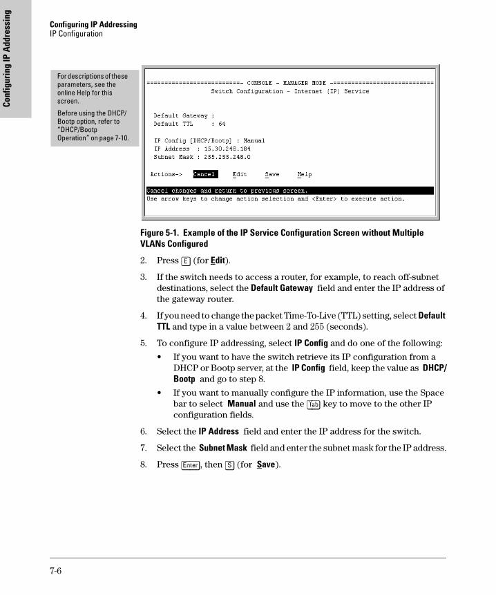
Configuring IP Addressing IP Configuration
Conf
igur
ing
IP A
ddre
ssin
g
Figure 5-1. Example of the IP Service Configuration Screen without Multiple VLANs Configured
2. Press [E] (for Edit).
3. If the switch needs to access a router, for example, to reach off-subnet destinations, select the Default Gateway field and enter the IP address of the gateway router.
4. If you need to change the packet Time-To-Live (TTL) setting, select Default TTL and type in a value between 2 and 255 (seconds).
5. To configure IP addressing, select IP Config and do one of the following:
• If you want to have the switch retrieve its IP configuration from a DHCP or Bootp server, at the IP Config field, keep the value as DHCP/Bootp and go to step 8.
• If you want to manually configure the IP information, use the Space bar to select Manual and use the [Tab] key to move to the other IP configuration fields.
6. Select the IP Address field and enter the IP address for the switch.
7. Select the Subnet Mask field and enter the subnet mask for the IP address.
8. Press [Enter], then [S] (for Save).
For descriptions of these parameters, see the online Help for this screen.
Before using the DHCP/Bootp option, refer to “DHCP/Bootp Operation” on page 7-10.
7-6
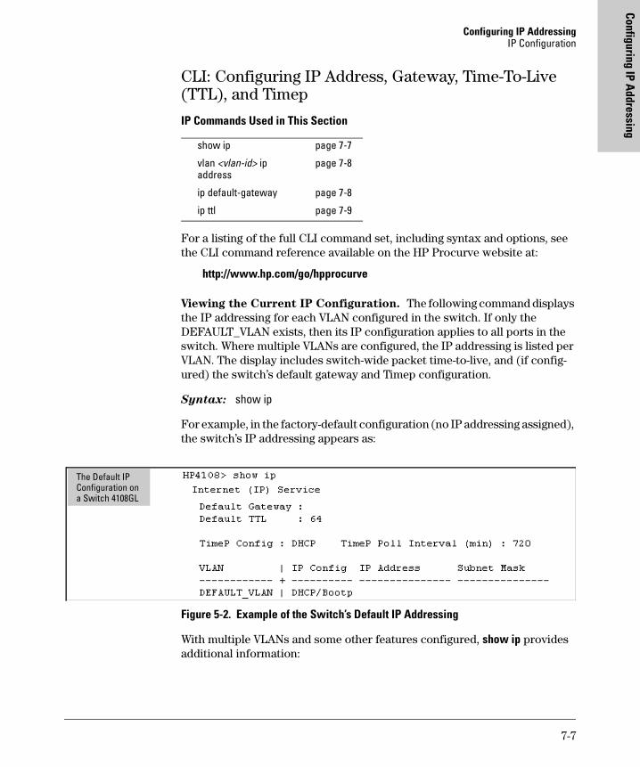
Configuring IP AddressingIP Configuration
Configuring IP Addressing
CLI: Configuring IP Address, Gateway, Time-To-Live (TTL), and Timep
IP Commands Used in This Section
For a listing of the full CLI command set, including syntax and options, see the CLI command reference available on the HP Procurve website at:
http://www.hp.com/go/hpprocurve
Viewing the Current IP Configuration. The following command displays the IP addressing for each VLAN configured in the switch. If only the DEFAULT_VLAN exists, then its IP configuration applies to all ports in the switch. Where multiple VLANs are configured, the IP addressing is listed per VLAN. The display includes switch-wide packet time-to-live, and (if config-ured) the switch’s default gateway and Timep configuration.
Syntax: show ip
For example, in the factory-default configuration (no IP addressing assigned), the switch’s IP addressing appears as:
Figure 5-2. Example of the Switch’s Default IP Addressing
With multiple VLANs and some other features configured, show ip provides additional information:
show ip page 7-7
vlan <vlan-id> ip address
page 7-8
ip default-gateway page 7-8
ip ttl page 7-9
The Default IP Configuration on a Switch 4108GL
7-7
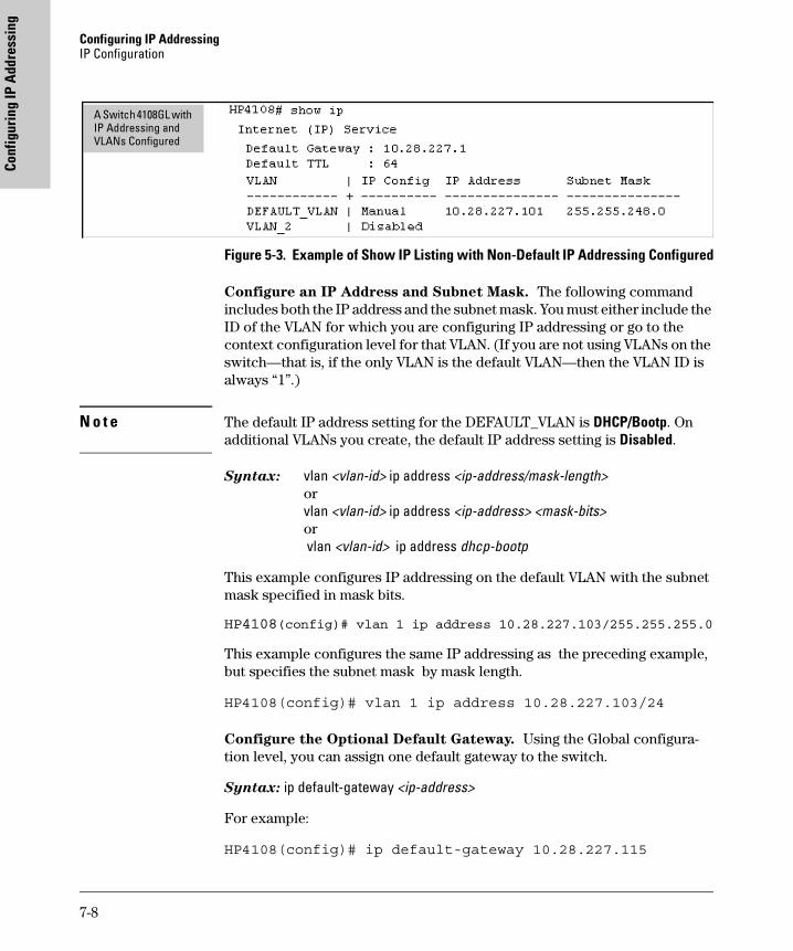
Configuring IP Addressing IP Configuration
Conf
igur
ing
IP A
ddre
ssin
g
Figure 5-3. Example of Show IP Listing with Non-Default IP Addressing Configured
Configure an IP Address and Subnet Mask. The following command includes both the IP address and the subnet mask. You must either include the ID of the VLAN for which you are configuring IP addressing or go to the context configuration level for that VLAN. (If you are not using VLANs on the switch—that is, if the only VLAN is the default VLAN—then the VLAN ID is always “1”.)
N o t e The default IP address setting for the DEFAULT_VLAN is DHCP/Bootp. On additional VLANs you create, the default IP address setting is Disabled.
Syntax: vlan <vlan-id> ip address <ip-address/mask-length>orvlan <vlan-id> ip address <ip-address> <mask-bits>or vlan <vlan-id> ip address dhcp-bootp
This example configures IP addressing on the default VLAN with the subnet mask specified in mask bits.
HP4108(config)# vlan 1 ip address 10.28.227.103/255.255.255.0
This example configures the same IP addressing as the preceding example, but specifies the subnet mask by mask length.
HP4108(config)# vlan 1 ip address 10.28.227.103/24
Configure the Optional Default Gateway. Using the Global configura-tion level, you can assign one default gateway to the switch.
Syntax: ip default-gateway <ip-address>
For example:
HP4108(config)# ip default-gateway 10.28.227.115
A Switch 4108GL with IP Addressing and VLANs Configured
7-8
Configuring IP AddressingIP Configuration
Configuring IP Addressing
Configure Time-To-Live (TTL). Use this command at the Global config prompt to set the time that a packet outbound from the switch can exist on the network. The default setting is 64 seconds.
Syntax: ip ttl <number-of-seconds>
HP4108(config)# ip ttl 60
In the CLI, you can execute this command only from the global configuration level. The TTL range is 2 - 255 seconds.
Web: Configuring IP Addressing
You can use the web browser interface to access IP addressing only if the switch already has an IP address that is reachable through your network.
1. Click on the Configuration tab.
2. Click on [IP Configuration].
3. If you need further information on using the web browser interface, click on [?] to access the web-based help available for the Switch 2512/2524.
How IP Addressing Affects Switch Operation
Without an IP address and subnet mask compatible with your network, the switch can be managed only through a direct terminal device connection to the Console RS-232 port. You can use direct-connect console access to take advantage of features that do not depend on IP addressing. However, to realize the full performance capabilities HP proactive networking offers through the switch, configure the switch with an IP address and subnet mask compatible with your network. The following table lists the general features available with and without a network-compatible IP address configured.
7-9
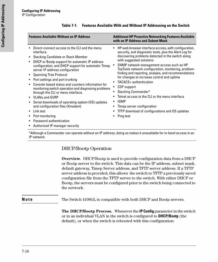
Configuring IP Addressing IP Configuration
Conf
igur
ing
IP A
ddre
ssin
g
Table 7-1. Features Available With and Without IP Addressing on the Switch
DHCP/Bootp Operation
Overview. DHCP/Bootp is used to provide configuration data from a DHCP or Bootp server to the switch. This data can be the IP address, subnet mask, default gateway, Timep Server address, and TFTP server address. If a TFTP server address is provided, this allows the switch to TFTP a previously saved configuration file from the TFTP server to the switch. With either DHCP or Bootp, the servers must be configured prior to the switch being connected to the network.
N o t e The Switch 4108GL is compatible with both DHCP and Bootp servers.
The DHCP/Bootp Process. Whenever the IP Config parameter in the switch or in an individual VLAN in the switch is configured to DHCP/Bootp (the default), or when the switch is rebooted with this configuration:
Features Available Without an IP Address Additional HP Proactive Networking Features Available with an IP Address and Subnet Mask
• Direct-connect access to the CLI and the menu interface.
• Stacking Candidate or Stack Member• DHCP or Bootp support for automatic IP address
configuration, and DHCP support for automatic Timep server IP address configuration
• Spanning Tree Protocol• Port settings and port trunking• Console-based status and counters information for
monitoring switch operation and diagnosing problems through the CLI or menu interface.
• VLANs and GVRP• Serial downloads of operating system (OS) updates
and configuration files (Xmodem)• Link test• Port monitoring• Password authentication• Authorized IP manager security
• HP web browser interface access, with configuration, security, and diagnostic tools, plus the Alert Log for discovering problems detected in the switch along with suggested solutions
• SNMP network management access such as HP TopTools network configuration, monitoring, problem-finding and reporting, analysis, and recommendations for changes to increase control and uptime
• TACACS+ authentication• CDP support• Stacking Commander*• Telnet access to the CLI or the menu interface• IGMP• Timep server configuration• TFTP download of configurations and OS updates• Ping test
*Although a Commander can operate without an IP address, doing so makes it unavailable for in-band access in an IP network.
7-10
Configuring IP AddressingIP Configuration
Configuring IP Addressing
1. DHCP/Bootp requests are automatically broadcast on the local network. (The switch sends one type of request to which either a DHCP or Bootp server can respond.)
2. When a DHCP or Bootp server receives the request, it replies with a previously configured IP address and subnet mask for the switch. The switch also receives an IP Gateway address if the server has been config-ured to provide one. In the case of Bootp, the server must first be configured with an entry that has the MAC address of the switch. (To determine the switch’s MAC address, see appendix B, “MAC Address Management”. The switch properly handles replies from either type of server. If multiple replies are returned, the switch tries to use the first reply.)
N o t e If you manually configure a gateway on the switch, it will ignore any gateway address received via DHCP or Bootp.
If the switch is initially configured for DHCP/Bootp operation (the default), or if it is rebooted with this configuration, it immediately begins sending request packets on the network. If the switch does not receive a reply to its DHCP/Bootp requests, it continues to periodically send request packets, but with decreasing frequency. Thus, if a DHCP or Bootp server is not available or accessible to the switch when DHCP/Bootp is first configured, the switch may not immediately receive the desired configuration. After verifying that the server has become accessible to the switch, reboot the switch to re-start the process immediately.
DHCP Operation. A significant difference between a DHCP configuration and a Bootp configuration is that an IP address assignment from a DHCP server is automatic. Depending on how the DHCP server is configured, the switch may receive an ip address that is temporarily leased. Periodically the switch may be required to renew its lease of the IP configuration. Thus, the IP addressing provided by the server may be different each time the switch reboots or renews its configuration from the server. However, you can fix the address assignment for the switch by doing either of the following:
� Configure the server to issue an “infinite” lease.
� Using the switch’s MAC address as an identifier, configure the server with a “Reservation” so that it will always assign the same IP address to the switch. (For MAC address information, refer to appendix B, “MAC Address Management”.)
For more information on either of these procedures, refer to the documenta-tion provided with the DHCP server.
7-11
Configuring IP Addressing IP Configuration
Conf
igur
ing
IP A
ddre
ssin
g
Bootp Operation. When a Bootp server receives a request it searches its Bootp database for a record entry that matches the MAC address in the Bootp request from the switch. If a match is found, the configuration data in the associated database record is returned to the switch. For many Unix systems, the Bootp database is contained in the /etc/bootptab file. In contrast to DHCP operation, Bootp configurations are always the same for a specific receiving device. That is, the Bootp server replies to a request with a configuration previously stored in the server and designated for the requesting device.
Bootp Database Record Entries. A minimal entry in the Bootp table file/etc/bootptab to update an IP address and subnet mask to the switch or a VLAN configured in the switch would be similar to this entry:
j4108switch:\ht=ether:\ha=0030c1123456:\ip=10.66.77.88:\sm=255.255.248.0:\gw=10.66.77.1:\hn:\vm=rfc1048
An entry in the Bootp table file /etc/bootptab to tell the switch or VLAN where to obtain a configuration file download would be similar to this entry:
j4108switch:\ht=ether:\ha=0030c1123456:\ip=10.66.77.88:\sm=255.255.248.0:\gw=10.66.77.1:\lg=10.22.33.44:\T144=”switch.cfg”:\vm=rfc1048
where:
j4108switch is a user-defined symbolic name to help you find the correct section of the bootptab file. If you have multiple switches that will be using Bootp to get their IP configuration, you should use a unique symbolic name for each switch.
ht is the “hardware type”. For the Switch 4108GL, set this to ether (for Ethernet). This tag must precede the ha tag.
ha is the “hardware address”. Use the switch's (or VLAN's) 12-digit MAC address.
ip is the IP address to be assigned to the switch (or VLAN).
sm is the subnet mask of the subnet in which the switch (or VLAN) is installed.
7-12
Configuring IP AddressingIP Configuration
Configuring IP Addressing
N o t e The above Bootp table entry is a sample that will work for the Switch 4108GL when the appropriate addresses and file names are used.
Network Preparations for Configuring DHCP/Bootp
In its default configuration, the switch is configured for DHCP/Bootp opera-tion. However, the DHCP/Bootp feature will not acquire IP addressing for the switch unless the following tasks have already been completed:
� For Bootp operation:
• A Bootp database record has already been entered into an appropriate Bootp server.
• The necessary network connections are in place
• The Bootp server is accessible from the switch
� For DHCP operation:
• A DHCP scope has been configured on the appropriate DHCP server.
• The necessary network connections are in place
• A DHCP server is accessible from the switch
N o t e Designating a primary VLAN other than the default VLAN affects the switch’s use of information received via DHCP/Bootp. For more on this topic, see “Which VLAN Is Primary?” on page 14-7.
After you reconfigure or reboot the switch with DHCP/Bootp enabled in a network providing DHCP/Bootp service, the switch does the following:
� Receives an IP address and subnet mask and, if configured in the server, a gateway IP address and the address of a Timep server.
� If the DHCP/Bootp reply provides information for downloading a config-uration file, the switch uses TFTP to download the file from the designated source, then reboots itself. (This assumes that the switch or VLAN has connectivity to the TFTP file server specified in the reply, that the config-uration file is correctly named, and that the configuration file exists in the TFTP directory.)
gw is the IP address of the default gateway.
lg TFTP server address (source of final configuration file)
T144 is the vendor-specific “tag” identifying the configuration file to download.
vm is a required entry that specifies the Bootp report format. For the Switches 2512 and 2524, set this parameter to rfc1048.
7-13
Configuring IP Addressing IP Configuration
Conf
igur
ing
IP A
ddre
ssin
g
Globally Assigned IP Network Addresses
If you intend to connect your network to other networks that use globally administered IP addresses, Hewlett-Packard strongly recommends that you use IP addresses that have a network address assigned to you. There is a formal process for assigning unique IP addresses to networks worldwide. For more information:
Please contact your internet service provider (ISP).
If you need more information than your ISP can provide, contact one of the following organizations:
For more information, refer to the latest edition of Internetworking with TCP/
IP: Principles, Protocols and Architecture by Douglas E. Comer (Prentice-Hall, Inc., publisher).
Country Phone Number/E-Mail/URL Organization Name/Address
United States/Countries not in Europe or Asia/Pacific
[email protected]://www.icann.org
The Internet Corporation for Assigned Names and Numbers (ICANN)4676 Admiralty Way, Suite 330Marina Del Rey, CA 90292USA
Europe +31 20 535 [email protected]://www.ripe.net
RIPE NCCSingel 2581016 AB AmsterdamThe Netherlands
Asia/Pacific [email protected]://www.apnic.net
Attention: IN-ADDR.ARPA RegistrationAsia Pacific Network Information CenterLevel 1, 33 Park RoadPO Box 2131Milton, QLD 4064Australia
7-14
Time Protocols
8
Time Protocols
Chapter Contents
Overview . . . . . . . . . . . . . . . . . . . . . . . . . . . . . . . . . . . . . . . . . . . . . . . . . . . . . . 8-2
TimeP Time Synchronization . . . . . . . . . . . . . . . . . . . . . . . . . . . . . . . . . . 8- 2
SNTP Time Synchronization . . . . . . . . . . . . . . . . . . . . . . . . . . . . . . . . . . 8-2
Overview: Selecting a Time Synchronization Protocol or Turning Off Time Protocol Operation . . . . . . . . . . . . . . . . . . . . . . . . . . . . . . . . . . . . . . . . . . . . . . 8-3
General Steps for Running a Time Protocol on the Switch: . . . . . . . . 8-3
Disabling Time Synchronization . . . . . . . . . . . . . . . . . . . . . . . . . . . . . . . 8-4
SNTP: Viewing, Selecting, and Configuring . . . . . . . . . . . . . . . . . . . . . . . . . 8-4
Menu: Viewing and Configuring SNTP . . . . . . . . . . . . . . . . . . . . . . . . . . 8-5
CLI: Viewing and Configuring SNTP . . . . . . . . . . . . . . . . . . . . . . . . . . . . 8-8Viewing the Current SNTP Configuration . . . . . . . . . . . . . . . . . . . . 8-8Configuring (Enabling or Disabling) the SNTP Mode . . . . . . . . . . 8-9
TimeP: Viewing, Selecting, and Configuring . . . . . . . . . . . . . . . . . . . . . . . . 8-13
Menu: Viewing and Configuring TimeP . . . . . . . . . . . . . . . . . . . . . . . . 8-14
CLI: Viewing and Configuring TimeP . . . . . . . . . . . . . . . . . . . . . . . . . . 8-16Viewing the Current TimeP Configuration . . . . . . . . . . . . . . . . . . 8-16Configuring (Enabling or Disabling) the TimeP Mode . . . . . . . . 8-17
SNTP Unicast Time Polling with Multiple SNTP Servers . . . . . . . . . . . . . 8-20
Address Prioritization . . . . . . . . . . . . . . . . . . . . . . . . . . . . . . . . . . . . . . . 8-21
Adding and Deleting SNTP Server Addresses . . . . . . . . . . . . . . . . . . . 8-21
Menu Interface Operation with Multiple SNTP Server Addresses Configured 8-23
SNTP Messages in the Event Log . . . . . . . . . . . . . . . . . . . . . . . . . . . . . . . . . 8-23
8-1
Time Protocols Overview
Tim
e Pr
otoc
ols
Overview
This chapter describes:
� SNTP Time Protocol Operation
� Timep Time Protocol Operation
Using time synchronization ensures a uniform time among interoperating devices. This helps you to manage and troubleshoot switch operation by attaching meaningful time data to event and error messages.
The switch offers TimeP and SNTP (Simple Network Time Protocol) and a timesync command for changing the time protocol selection (or turning off time protocol operation).
Notes� Although you can create and save configurations for both time proto-
cols without conflicts, the switch allows only one active time protocol at any time.
� In the factory-default configuration, the time synchronization option is set to TimeP, with the TimeP mode itself set to Disabled.
TimeP Time Synchronization
You can either manually assign the switch to use a TimeP server or use DHCP to assign the TimeP server. In either case, the switch can get its time synchro-nization updates from only one, designated Timep server. This option enhances security by specifying which time server to use.
SNTP Time Synchronization
SNTP provides two operating modes:
� Broadcast Mode: The switch acquires time updates by accepting the time value from the first SNTP time broadcast detected. (In this case, the SNTP server must be configured to broadcast time updates to the network broadcast address. Refer to the documentation provided with your SNTP server application.) Once the switch detects a partic-
8-2
Time ProtocolsOverview: Selecting a Time Synchronization Protocol or Turning Off Time Protocol Operation
Time Protocols
ular server, it ignores time broadcasts from other SNTP servers unless the configurable Poll Interval expires three consecutive times without an update received from the first-detected server.
NoteTo use Broadcast mode, the switch and the SNTP server must be in the same subnet.
� Unicast Mode: The switch requests a time update from the config-ured SNTP server. (You can configure one server using the menu interface, or up to three servers using the CLI sntp server command.) This option provides increased security over the Broadcast mode by specifying which time server to use instead of using the first one detected through a broadcast.
Overview: Selecting a Time Synchronization Protocol or Turning Off Time Protocol Operation
General Steps for Running a Time Protocol on the Switch:
1. Select the time synchronization protocol: SNTP or TimeP (the default).
2. Enable the protocol. The choices are:
• SNTP: Broadcast or Unicast
• TimeP: DHCP or Manual
3. Configure the remaining parameters for the time protocol you selected.
The switch retains the parameter settings for both time protocols even if you change from one protocol to the other. Thus, if you select a time protocol, the switch uses the parameters you last configured for the selected protocol.
8-3
Time Protocols SNTP: Viewing, Selecting, and Configuring
Tim
e Pr
otoc
ols
Note that simply selecting a time synchronization protocol does not enable that protocol on the switch unless you also enable the protocol itself (step 2, above). For example, in the factory-default configuration, TimeP is the selected time synchronization method. However, because TimeP is disabled in the factory-default configuration, no time synchronization protocol is running.
Disabling Time Synchronization
You can use either of the following methods to disable time synchronization without changing the Timep or SNTP configuration:
� In the System Information screen of the Menu interface, set the Time Synch Method parameter to None, then press [Enter], then [S] (for Save).
� In the Global config level of the CLI, execute no timesync.
SNTP: Viewing, Selecting, and Configuring
SNTP Feature Default Menu CLI Web
view the SNTP time synchronization configuration n/a page 8-5 page 8-8 —
select SNTP as the time synchronization method timep page 8-6 page 8-9 ff. —
disable time synchronization timep page 8-6 page 8-12 —
enable the SNTP mode (Broadcast, Unicast, or Disabled) disabled —
broadcast n/a page 8-6 page 8-9 —
unicast n/a page 8-6 page 8-10 —
none/disabled n/a page 8-6 page 8-12 —
configure an SNTP server address (for Unicast mode only) none page 8-6 page 8-10 ff. —
change the SNTP server version (for Unicast mode only) 3 page 8-7 page 8-11 —
change the SNTP poll interval 720 seconds page 8-7 page 8-12 —
8-4
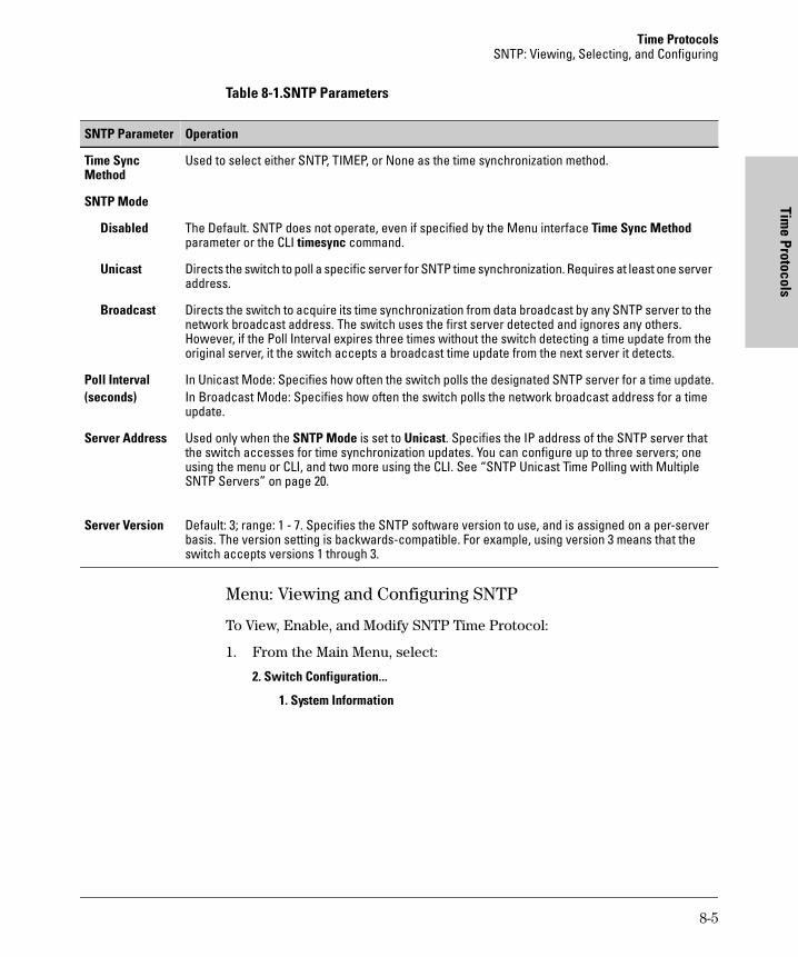
Time ProtocolsSNTP: Viewing, Selecting, and Configuring
Time Protocols
Table 8-1.SNTP Parameters
Menu: Viewing and Configuring SNTP
To View, Enable, and Modify SNTP Time Protocol:
1. From the Main Menu, select:
2. Switch Configuration...
1. System Information
SNTP Parameter Operation
Time Sync Method
Used to select either SNTP, TIMEP, or None as the time synchronization method.
SNTP Mode
Disabled The Default. SNTP does not operate, even if specified by the Menu interface Time Sync Method parameter or the CLI timesync command.
Unicast Directs the switch to poll a specific server for SNTP time synchronization. Requires at least one server address.
Broadcast Directs the switch to acquire its time synchronization from data broadcast by any SNTP server to the network broadcast address. The switch uses the first server detected and ignores any others. However, if the Poll Interval expires three times without the switch detecting a time update from the original server, it the switch accepts a broadcast time update from the next server it detects.
Poll Interval(seconds)
In Unicast Mode: Specifies how often the switch polls the designated SNTP server for a time update.In Broadcast Mode: Specifies how often the switch polls the network broadcast address for a time update.
Server Address Used only when the SNTP Mode is set to Unicast. Specifies the IP address of the SNTP server that the switch accesses for time synchronization updates. You can configure up to three servers; one using the menu or CLI, and two more using the CLI. See “SNTP Unicast Time Polling with Multiple SNTP Servers” on page 20.
Server Version Default: 3; range: 1 - 7. Specifies the SNTP software version to use, and is assigned on a per-server basis. The version setting is backwards-compatible. For example, using version 3 means that the switch accepts versions 1 through 3.
8-5
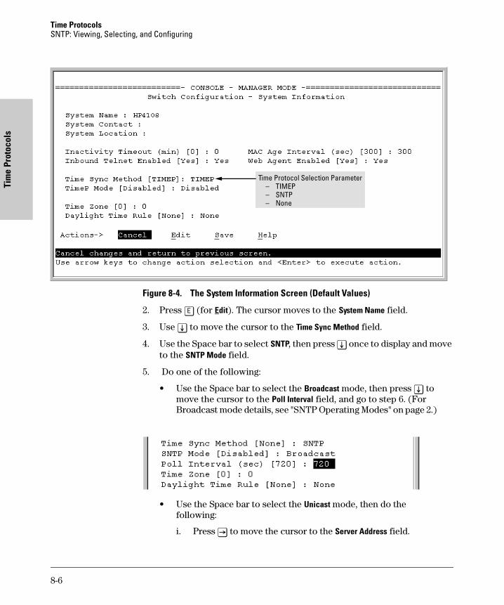
Time Protocols SNTP: Viewing, Selecting, and Configuring
Tim
e Pr
otoc
ols
Figure 8-4. The System Information Screen (Default Values)
2. Press [E] (for Edit). The cursor moves to the System Name field.
3. Use [v] to move the cursor to the Time Sync Method field.
4. Use the Space bar to select SNTP, then press [v] once to display and move to the SNTP Mode field.
5. Do one of the following:
• Use the Space bar to select the Broadcast mode, then press [v] to move the cursor to the Poll Interval field, and go to step 6. (For Broadcast mode details, see "SNTP Operating Modes" on page 2.)
• Use the Space bar to select the Unicast mode, then do the following:
i. Press [>] to move the cursor to the Server Address field.
Time Protocol Selection Parameter– TIMEP – SNTP– None
8-6
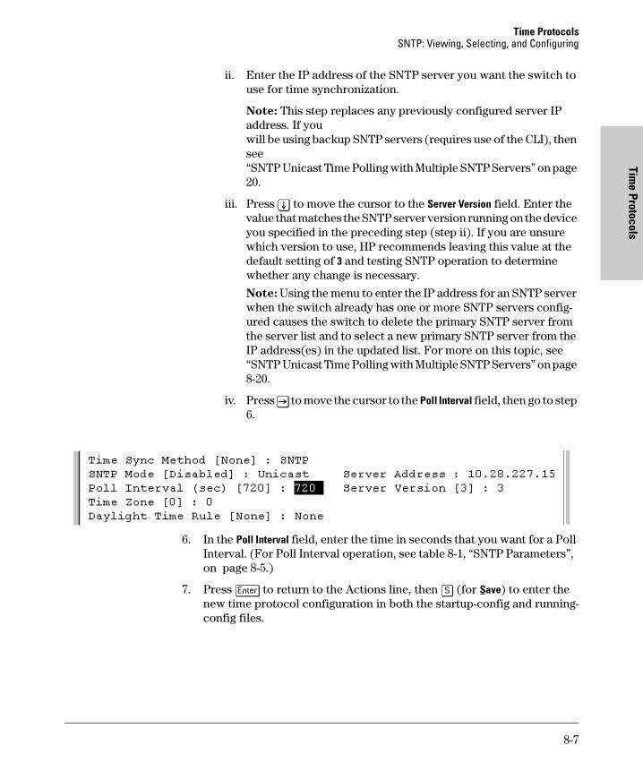
Time ProtocolsSNTP: Viewing, Selecting, and Configuring
Time Protocols
ii. Enter the IP address of the SNTP server you want the switch to use for time synchronization.
Note: This step replaces any previously configured server IP address. If you will be using backup SNTP servers (requires use of the CLI), then see “SNTP Unicast Time Polling with Multiple SNTP Servers” on page 20.
iii. Press [v] to move the cursor to the Server Version field. Enter the value that matches the SNTP server version running on the device you specified in the preceding step (step ii). If you are unsure which version to use, HP recommends leaving this value at the default setting of 3 and testing SNTP operation to determine whether any change is necessary.
Note: Using the menu to enter the IP address for an SNTP server when the switch already has one or more SNTP servers config-ured causes the switch to delete the primary SNTP server from the server list and to select a new primary SNTP server from the IP address(es) in the updated list. For more on this topic, see “SNTP Unicast Time Polling with Multiple SNTP Servers” on page 8-20.
iv. Press [>] to move the cursor to the Poll Interval field, then go to step 6.
6. In the Poll Interval field, enter the time in seconds that you want for a Poll Interval. (For Poll Interval operation, see table 8-1, “SNTP Parameters”, on page 8-5.)
7. Press [Enter] to return to the Actions line, then [S] (for Save) to enter the new time protocol configuration in both the startup-config and running-config files.
8-7
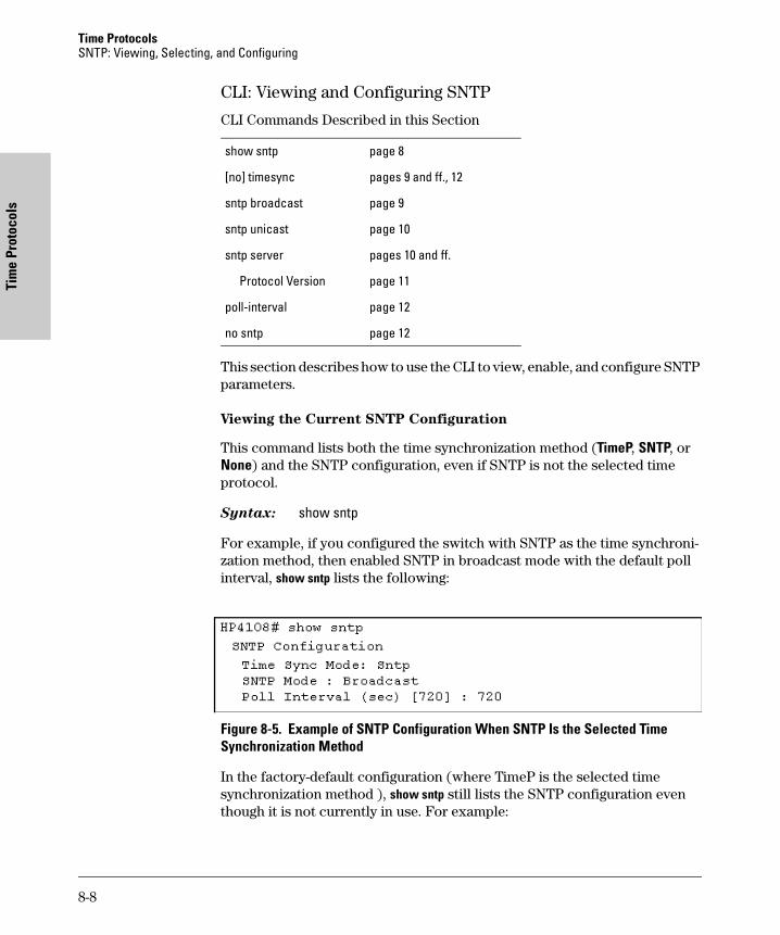
Time Protocols SNTP: Viewing, Selecting, and Configuring
Tim
e Pr
otoc
ols
CLI: Viewing and Configuring SNTP
CLI Commands Described in this Section
This section describes how to use the CLI to view, enable, and configure SNTP parameters.
Viewing the Current SNTP Configuration
This command lists both the time synchronization method (TimeP, SNTP, or None) and the SNTP configuration, even if SNTP is not the selected time protocol.
Syntax: show sntp
For example, if you configured the switch with SNTP as the time synchroni-zation method, then enabled SNTP in broadcast mode with the default poll interval, show sntp lists the following:
Figure 8-5. Example of SNTP Configuration When SNTP Is the Selected Time Synchronization Method
In the factory-default configuration (where TimeP is the selected time synchronization method ), show sntp still lists the SNTP configuration even though it is not currently in use. For example:
show sntp page 8
[no] timesync pages 9 and ff., 12
sntp broadcast page 9
sntp unicast page 10
sntp server pages 10 and ff.
Protocol Version page 11
poll-interval page 12
no sntp page 12
8-8
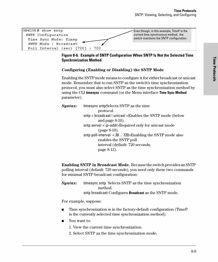
Time ProtocolsSNTP: Viewing, Selecting, and Configuring
Time Protocols
Figure 8-6. Example of SNTP Configuration When SNTP Is Not the Selected Time Synchronization Method
Configuring (Enabling or Disabling) the SNTP Mode
Enabling the SNTP mode means to configure it for either broadcast or unicast mode. Remember that to run SNTP as the switch’s time synchronization protocol, you must also select SNTP as the time synchronization method by using the CLI timesync command (or the Menu interface Time Sync Method parameter).
Syntax: timesync sntpSelects SNTP as the timeprotocol.
sntp < broadcast | unicast >Enables the SNTP mode (belowand page 8-10).
sntp server < ip-addr>Required only for unicast mode(page 8-10).
sntp poll-interval < 30 . . 720>Enabling the SNTP mode alsoenables the SNTP pollinterval (default: 720 seconds;page 8-12).
Enabling SNTP in Broadcast Mode. Because the switch provides an SNTP polling interval (default: 720 seconds), you need only these two commands for minimal SNTP broadcast configuration:
Syntax: timesync sntp Selects SNTP as the time synchronizationmethod.
sntp broadcast Configures Broadcast as the SNTP mode.
For example, suppose:
� Time synchronization is in the factory-default configuration (TimeP is the currently selected time synchronization method).
� You want to:
1. View the current time synchronization.
2. Select SNTP as the time synchronization mode.
Even though, in this example, TimeP is the current time synchronous method, the switch maintains the SNTP configuration.
8-9
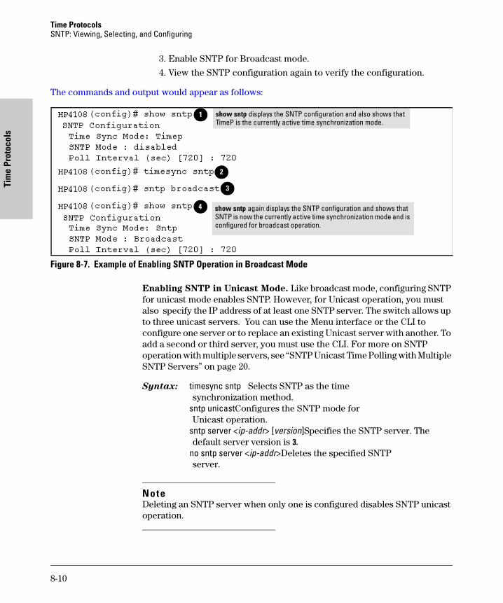
Time Protocols SNTP: Viewing, Selecting, and Configuring
Tim
e Pr
otoc
ols
3. Enable SNTP for Broadcast mode.
4. View the SNTP configuration again to verify the configuration.
The commands and output would appear as follows:
Figure 8-7. Example of Enabling SNTP Operation in Broadcast Mode
Enabling SNTP in Unicast Mode. Like broadcast mode, configuring SNTP for unicast mode enables SNTP. However, for Unicast operation, you must also specify the IP address of at least one SNTP server. The switch allows up to three unicast servers. You can use the Menu interface or the CLI to configure one server or to replace an existing Unicast server with another. To add a second or third server, you must use the CLI. For more on SNTP operation with multiple servers, see “SNTP Unicast Time Polling with Multiple SNTP Servers” on page 20.
Syntax: timesync sntp Selects SNTP as the time synchronization method.
sntp unicastConfigures the SNTP mode forUnicast operation.
sntp server <ip-addr> [version]Specifies the SNTP server. Thedefault server version is 3.
no sntp server <ip-addr>Deletes the specified SNTPserver.
NoteDeleting an SNTP server when only one is configured disables SNTP unicast operation.
show sntp displays the SNTP configuration and also shows that TimeP is the currently active time synchronization mode.
1
2
3
show sntp again displays the SNTP configuration and shows that SNTP is now the currently active time synchronization mode and is configured for broadcast operation.
4
8-10
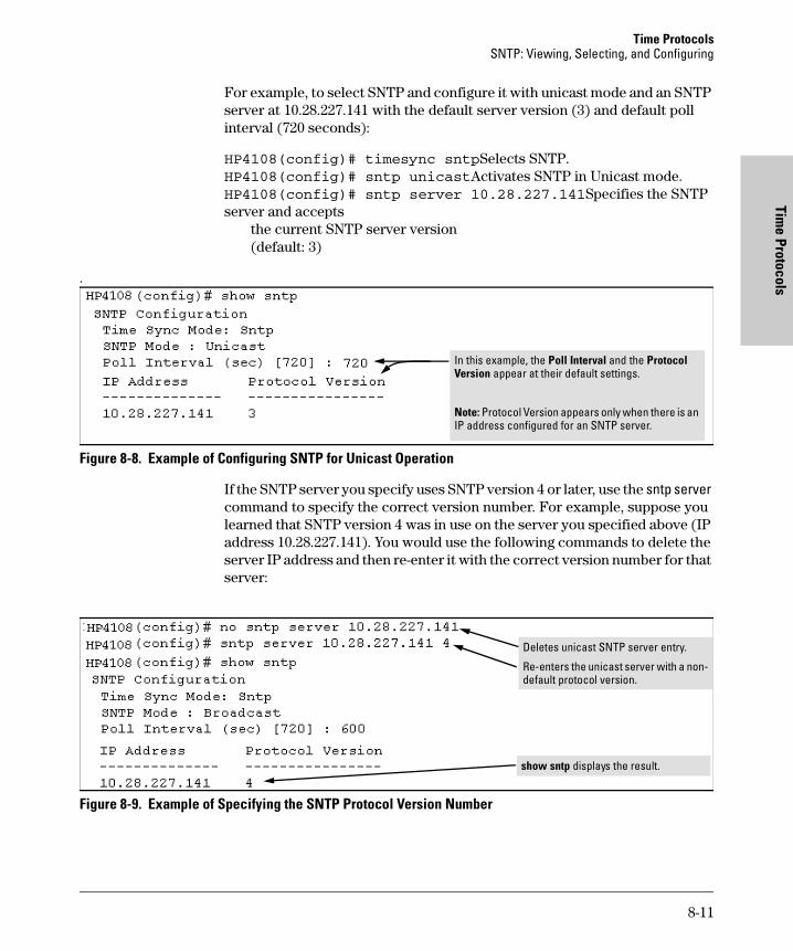
Time ProtocolsSNTP: Viewing, Selecting, and Configuring
Time Protocols
For example, to select SNTP and configure it with unicast mode and an SNTP server at 10.28.227.141 with the default server version (3) and default poll interval (720 seconds):
HP4108(config)# timesync sntpSelects SNTP.HP4108(config)# sntp unicastActivates SNTP in Unicast mode.HP4108(config)# sntp server 10.28.227.141Specifies the SNTP server and accepts
the current SNTP server version(default: 3)
.
Figure 8-8. Example of Configuring SNTP for Unicast Operation
If the SNTP server you specify uses SNTP version 4 or later, use the sntp server command to specify the correct version number. For example, suppose you learned that SNTP version 4 was in use on the server you specified above (IP address 10.28.227.141). You would use the following commands to delete the server IP address and then re-enter it with the correct version number for that server:
Figure 8-9. Example of Specifying the SNTP Protocol Version Number
In this example, the Poll Interval and the Protocol Version appear at their default settings.
Note: Protocol Version appears only when there is an IP address configured for an SNTP server.
Deletes unicast SNTP server entry.
Re-enters the unicast server with a non-default protocol version.
show sntp displays the result.
8-11
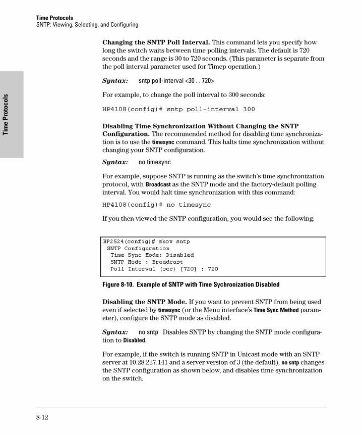
Time Protocols SNTP: Viewing, Selecting, and Configuring
Tim
e Pr
otoc
ols
Changing the SNTP Poll Interval. This command lets you specify how long the switch waits between time polling intervals. The default is 720 seconds and the range is 30 to 720 seconds. (This parameter is separate from the poll interval parameter used for Timep operation.)
Syntax: sntp poll-interval <30 . . 720>
For example, to change the poll interval to 300 seconds:
HP4108(config)# sntp poll-interval 300
Disabling Time Synchronization Without Changing the SNTP
Configuration. The recommended method for disabling time synchroniza-tion is to use the timesync command. This halts time synchronization without changing your SNTP configuration.
Syntax: no timesync
For example, suppose SNTP is running as the switch’s time synchronization protocol, with Broadcast as the SNTP mode and the factory-default polling interval. You would halt time synchronization with this command:
HP4108(config)# no timesync
If you then viewed the SNTP configuration, you would see the following:
Figure 8-10. Example of SNTP with Time Sychronization Disabled
Disabling the SNTP Mode. If you want to prevent SNTP from being used even if selected by timesync (or the Menu interface’s Time Sync Method param-eter), configure the SNTP mode as disabled.
Syntax: no sntp Disables SNTP by changing the SNTP mode configura-tion to Disabled.
For example, if the switch is running SNTP in Unicast mode with an SNTP server at 10.28.227.141 and a server version of 3 (the default), no sntp changes the SNTP configuration as shown below, and disables time synchronization on the switch.
8-12
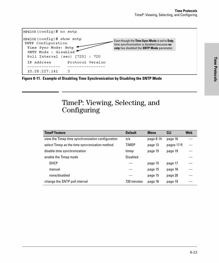
Time ProtocolsTimeP: Viewing, Selecting, and Configuring
Time Protocols
Figure 8-11. Example of Disabling Time Synchronization by Disabling the SNTP ModeTimeP: Viewing, Selecting, and Configuring
Even though the Time Sync Mode is set to Sntp, time synchronization is disabled because no sntp has disabled the SNTP Mode parameter.
TimeP Feature Default Menu CLI Web
view the Timep time synchronization configuration n/a page 8-14 page 16 —
select Timep as the time syncronization method TIMEP page 13 pages 17 ff. —
disable time synchronization timep page 15 page 19 —
enable the Timep mode Disabled —
DHCP — page 15 page 17 —
manual — page 15 page 18 —
none/disabled — page 15 page 20 —
change the SNTP poll interval 720 minutes page 16 page 19 —
8-13
Time Protocols TimeP: Viewing, Selecting, and Configuring
Tim
e Pr
otoc
ols
Table 8-2.Timep Parameters
Menu: Viewing and Configuring TimeP
To View, Enable, and Modify the TimeP Protocol:
1. From the Main Menu, select:
2. Switch Configuration...
1. System Information
SNTP Parameter Operation
Time Sync Method
Used to select either TIMEP (the default), SNTP, or None as the time synchronization method.
Timep Mode
Disabled The Default. Timep does not operate, even if specified by the Menu interface Time Sync Method parameter or the CLI timesync command.
DHCP When Timep is selected as the time synchronization method, the switch attempts to acquire a Timep server IP address via DHCP. If the switch receives a server address, it polls the server for updates according to the Timep poll interval. If the switch does not receive a Timep server IP address, it cannot perform time synchronization updates.
Manual When Timep is selected as the time synchronization method, the switch attempts to poll the specified server for updates according to the Timep poll interval. If the switch fails to receive updates from the server, time synchronization updates do not occur.
Server Address
Used only when the TimeP Mode is set to Manual. Specifies the IP address of the TimeP server that the switch accesses for time synchronization updates. You can configure one server.
Poll Interval(minutes)
Default: 720 minutes. Specifies the interval the switch waits between attempts to poll the TimeP server for updates.
8-14
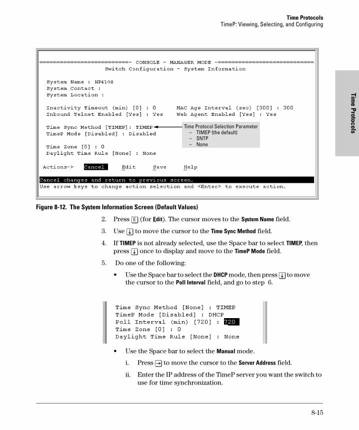
Time ProtocolsTimeP: Viewing, Selecting, and Configuring
Time Protocols
Figure 8-12. The System Information Screen (Default Values)
2. Press [E] (for Edit). The cursor moves to the System Name field.
3. Use [v] to move the cursor to the Time Sync Method field.
4. If TIMEP is not already selected, use the Space bar to select TIMEP, then press [v] once to display and move to the TimeP Mode field.
5. Do one of the following:
• Use the Space bar to select the DHCP mode, then press [v] to move the cursor to the Poll Interval field, and go to step 6.
• Use the Space bar to select the Manual mode.
i. Press [>] to move the cursor to the Server Address field.
ii. Enter the IP address of the TimeP server you want the switch to use for time synchronization.
Time Protocol Selection Parameter– TIMEP (the default)– SNTP– None
8-15
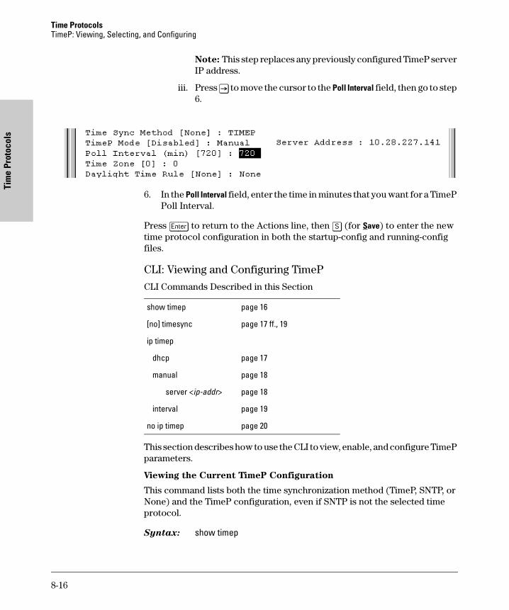
Time Protocols TimeP: Viewing, Selecting, and Configuring
Tim
e Pr
otoc
ols
Note: This step replaces any previously configured TimeP server IP address.
iii. Press [>] to move the cursor to the Poll Interval field, then go to step 6.
6. In the Poll Interval field, enter the time in minutes that you want for a TimeP Poll Interval.
Press [Enter] to return to the Actions line, then [S] (for Save) to enter the new time protocol configuration in both the startup-config and running-config files.
CLI: Viewing and Configuring TimeP
CLI Commands Described in this Section
This section describes how to use the CLI to view, enable, and configure TimeP parameters.
Viewing the Current TimeP Configuration
This command lists both the time synchronization method (TimeP, SNTP, or None) and the TimeP configuration, even if SNTP is not the selected time protocol.
Syntax: show timep
show timep page 16
[no] timesync page 17 ff., 19
ip timep
dhcp page 17
manual page 18
server <ip-addr> page 18
interval page 19
no ip timep page 20
8-16
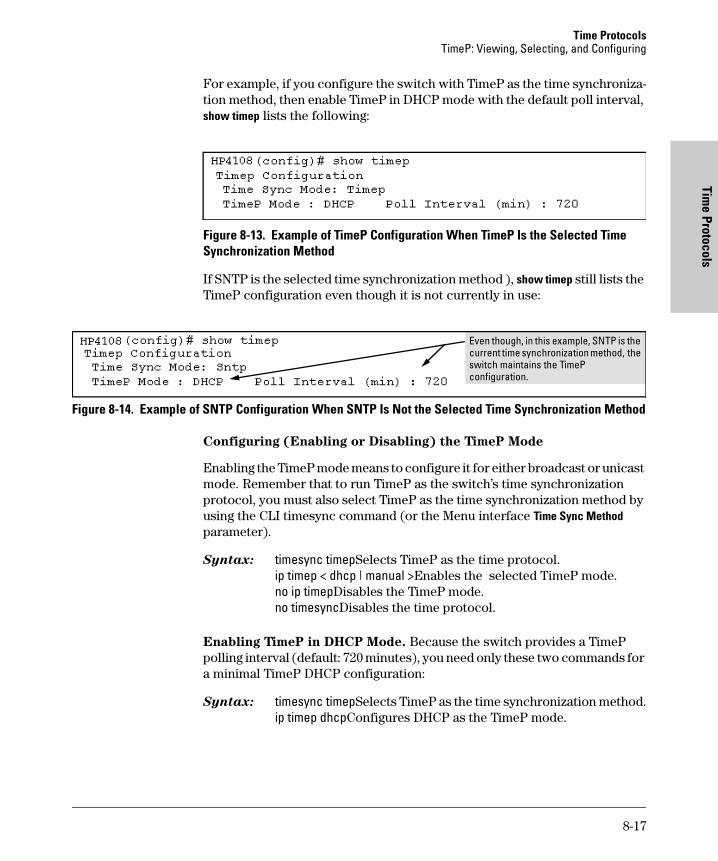
Time ProtocolsTimeP: Viewing, Selecting, and Configuring
Time Protocols
For example, if you configure the switch with TimeP as the time synchroniza-tion method, then enable TimeP in DHCP mode with the default poll interval, show timep lists the following:
Figure 8-13. Example of TimeP Configuration When TimeP Is the Selected Time Synchronization Method
If SNTP is the selected time synchronization method ), show timep still lists the TimeP configuration even though it is not currently in use:
Figure 8-14. Example of SNTP Configuration When SNTP Is Not the Selected Time Synchronization Method
Configuring (Enabling or Disabling) the TimeP Mode
Enabling the TimeP mode means to configure it for either broadcast or unicast mode. Remember that to run TimeP as the switch’s time synchronization protocol, you must also select TimeP as the time synchronization method by using the CLI timesync command (or the Menu interface Time Sync Method parameter).
Syntax: timesync timepSelects TimeP as the time protocol.ip timep < dhcp | manual >Enables the selected TimeP mode.no ip timepDisables the TimeP mode.no timesyncDisables the time protocol.
Enabling TimeP in DHCP Mode. Because the switch provides a TimeP polling interval (default: 720 minutes), you need only these two commands for a minimal TimeP DHCP configuration:
Syntax: timesync timepSelects TimeP as the time synchronization method.ip timep dhcpConfigures DHCP as the TimeP mode.
Even though, in this example, SNTP is the current time synchronization method, the switch maintains the TimeP configuration.
8-17
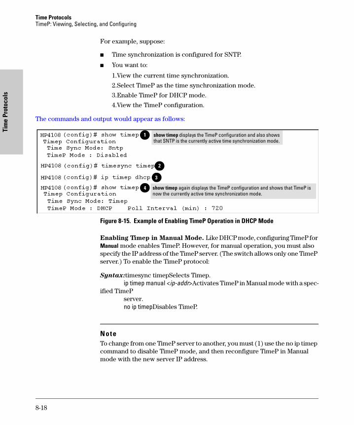
Time Protocols TimeP: Viewing, Selecting, and Configuring
Tim
e Pr
otoc
ols
For example, suppose:
� Time synchronization is configured for SNTP.
� You want to:
1.View the current time synchronization.
2.Select TimeP as the time synchronization mode.
3.Enable TimeP for DHCP mode.
4.View the TimeP configuration.
The commands and output would appear as follows:
Figure 8-15. Example of Enabling TimeP Operation in DHCP Mode
Enabling Timep in Manual Mode. Like DHCP mode, configuring TimeP for Manual mode enables TimeP. However, for manual operation, you must also specify the IP address of the TimeP server. (The switch allows only one TimeP server.) To enable the TimeP protocol:
Syntax:timesync timepSelects Timep.ip timep manual <ip-addr>Activates TimeP in Manual mode with a spec-
ified TimePserver.no ip timepDisables TimeP.
NoteTo change from one TimeP server to another, you must (1) use the no ip timep command to disable TimeP mode, and then reconfigure TimeP in Manual mode with the new server IP address.
show timep displays the TimeP configuration and also shows that SNTP is the currently active time synchronization mode.
1
2
3
4 show timep again displays the TimeP configuration and shows that TimeP is now the currently active time synchronization mode.
8-18
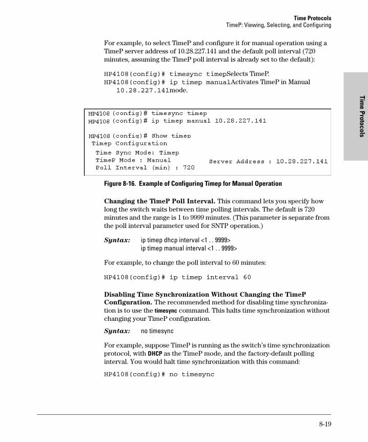
Time ProtocolsTimeP: Viewing, Selecting, and Configuring
Time Protocols
For example, to select TimeP and configure it for manual operation using a TimeP server address of 10.28.227.141 and the default poll interval (720 minutes, assuming the TimeP poll interval is already set to the default):
HP4108(config)# timesync timepSelects TimeP.HP4108(config)# ip timep manualActivates TimeP in Manual 10.28.227.141mode.
Figure 8-16. Example of Configuring Timep for Manual Operation
Changing the TimeP Poll Interval. This command lets you specify how long the switch waits between time polling intervals. The default is 720 minutes and the range is 1 to 9999 minutes. (This parameter is separate from the poll interval parameter used for SNTP operation.)
Syntax: ip timep dhcp interval <1 . . 9999>ip timep manual interval <1 . . 9999>
For example, to change the poll interval to 60 minutes:
HP4108(config)# ip timep interval 60
Disabling Time Synchronization Without Changing the TimeP
Configuration. The recommended method for disabling time synchroniza-tion is to use the timesync command. This halts time synchronization without changing your TimeP configuration.
Syntax: no timesync
For example, suppose TimeP is running as the switch’s time synchronization protocol, with DHCP as the TimeP mode, and the factory-default polling interval. You would halt time synchronization with this command:
HP4108(config)# no timesync
8-19
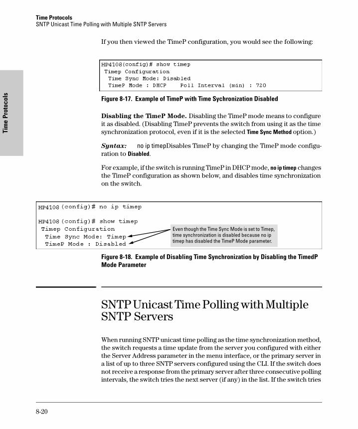
Time Protocols SNTP Unicast Time Polling with Multiple SNTP Servers
Tim
e Pr
otoc
ols
If you then viewed the TimeP configuration, you would see the following:
Figure 8-17. Example of TimeP with Time Sychronization Disabled
Disabling the TimeP Mode. Disabling the TimeP mode means to configure it as disabled. (Disabling TimeP prevents the switch from using it as the time synchronization protocol, even if it is the selected Time Sync Method option.)
Syntax: no ip timepDisables TimeP by changing the TimeP mode configu-ration to Disabled.
For example, if the switch is running TimeP in DHCP mode, no ip timep changes the TimeP configuration as shown below, and disables time synchronization on the switch.
Figure 8-18. Example of Disabling Time Synchronization by Disabling the TimedP Mode Parameter
SNTP Unicast Time Polling with Multiple SNTP Servers
When running SNTP unicast time polling as the time synchronization method, the switch requests a time update from the server you configured with either the Server Address parameter in the menu interface, or the primary server in a list of up to three SNTP servers configured using the CLI. If the switch does not receive a response from the primary server after three consecutive polling intervals, the switch tries the next server (if any) in the list. If the switch tries
Even though the Time Sync Mode is set to Timep, time synchronization is disabled because no ip timep has disabled the TimeP Mode parameter.
8-20
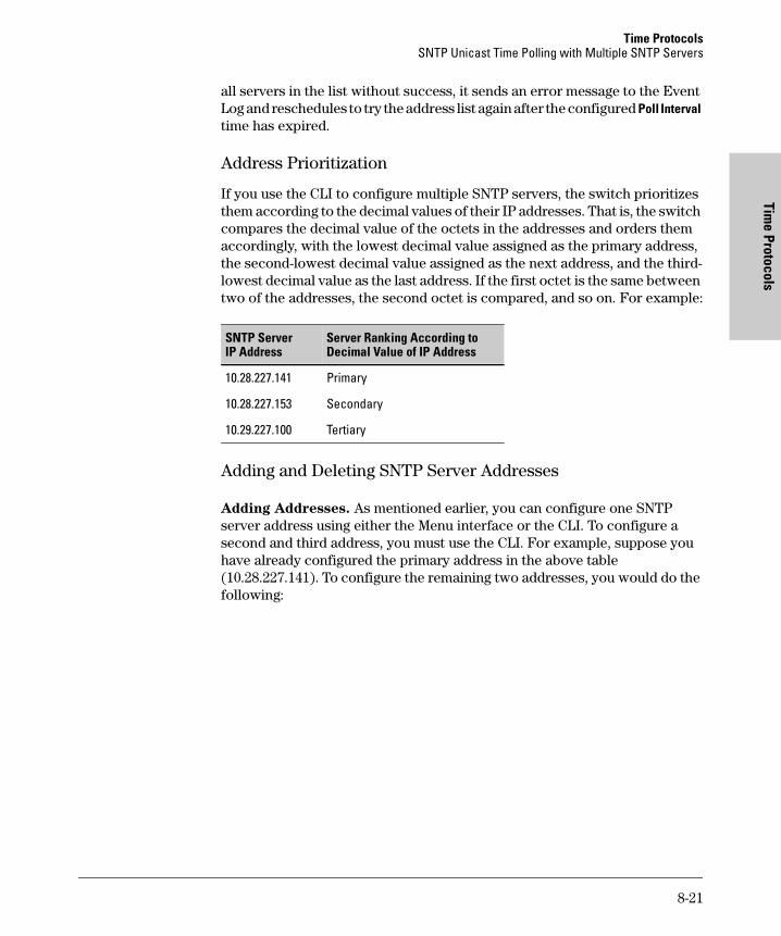
Time ProtocolsSNTP Unicast Time Polling with Multiple SNTP Servers
Time Protocols
all servers in the list without success, it sends an error message to the Event Log and reschedules to try the address list again after the configured Poll Interval time has expired.
Address Prioritization
If you use the CLI to configure multiple SNTP servers, the switch prioritizes them according to the decimal values of their IP addresses. That is, the switch compares the decimal value of the octets in the addresses and orders them accordingly, with the lowest decimal value assigned as the primary address, the second-lowest decimal value assigned as the next address, and the third-lowest decimal value as the last address. If the first octet is the same between two of the addresses, the second octet is compared, and so on. For example:
Adding and Deleting SNTP Server Addresses
Adding Addresses. As mentioned earlier, you can configure one SNTP server address using either the Menu interface or the CLI. To configure a second and third address, you must use the CLI. For example, suppose you have already configured the primary address in the above table (10.28.227.141). To configure the remaining two addresses, you would do the following:
SNTP Server IP Address
Server Ranking According to Decimal Value of IP Address
10.28.227.141 Primary
10.28.227.153 Secondary
10.29.227.100 Tertiary
8-21
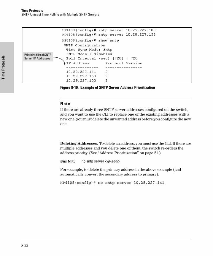
Time Protocols SNTP Unicast Time Polling with Multiple SNTP Servers
Tim
e Pr
otoc
ols
Figure 8-19. Example of SNTP Server Address Prioritization
Note If there are already three SNTP server addresses configured on the switch, and you want to use the CLI to replace one of the existing addresses with a new one, you must delete the unwanted address before you configure the new one.
Deleting Addresses. To delete an address, you must use the CLI. If there are multiple addresses and you delete one of them, the switch re-orders the address priority. (See “Address Prioritization” on page 21.)
Syntax: no sntp server <ip-addr>
For example, to delete the primary address in the above example (and automatically convert the secondary address to primary):
HP4108(config)# no sntp server 10.28.227.141
Prioritized list of SNTP Server IP Addresses
8-22
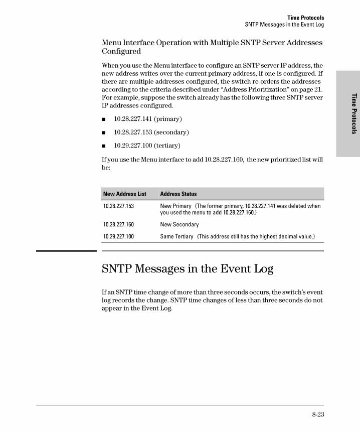
Time ProtocolsSNTP Messages in the Event Log
Time Protocols
Menu Interface Operation with Multiple SNTP Server Addresses Configured
When you use the Menu interface to configure an SNTP server IP address, the new address writes over the current primary address, if one is configured. If there are multiple addresses configured, the switch re-orders the addresses according to the criteria described under “Address Prioritization” on page 21. For example, suppose the switch already has the following three SNTP server IP addresses configured.
� 10.28.227.141 (primary)
� 10.28.227.153 (secondary)
� 10.29.227.100 (tertiary)
If you use the Menu interface to add 10.28.227.160, the new prioritized list will be:
SNTP Messages in the Event Log
If an SNTP time change of more than three seconds occurs, the switch’s event log records the change. SNTP time changes of less than three seconds do not appear in the Event Log.
New Address List Address Status
10.28.227.153 New Primary (The former primary, 10.28.227.141 was deleted when you used the menu to add 10.28.227.160.)
10.28.227.160 New Secondary
10.29.227.100 Same Tertiary (This address still has the highest decimal value.)
8-23

Time Protocols SNTP Messages in the Event Log
Tim
e Pr
otoc
ols
8-24
Using Passw
ords and TA
CACS+
9
Using Passwords and TACACS+ To Protect Against Unauthorized Access
Contents
Overview . . . . . . . . . . . . . . . . . . . . . . . . . . . . . . . . . . . . . . . . . . . . . . . . . . . . . 9-2
Configuring Username and Password Security . . . . . . . . . . . . . . . . . . 9-3
Menu: Configuring Passwords . . . . . . . . . . . . . . . . . . . . . . . . . . . . . . . . . 9-5
CLI: Setting Manager and Operator Passwords . . . . . . . . . . . . . . . . . . . 9-6
Web: Configuring User-Names and Passwords . . . . . . . . . . . . . . . . . . . 9-7
TACACS+ Authentication for Central Control of Switch
Access Security . . . . . . . . . . . . . . . . . . . . . . . . . . . . . . . . . . . . . . . . . . . . . . . 9-8
Terminology Used in TACACS Applications: . . . . . . . . . . . . . . . . . . . . 9-9
General System Requirements . . . . . . . . . . . . . . . . . . . . . . . . . . . . . . . . 9-10
General Authentication Setup Procedure . . . . . . . . . . . . . . . . . . . . . . 9-11
Configuring TACACS+ on the Switch . . . . . . . . . . . . . . . . . . . . . . . . . . 9-14Before You Begin . . . . . . . . . . . . . . . . . . . . . . . . . . . . . . . . . . . . . . . 9-14Viewing the Switch’s Current Authentication Configuration . . . 9-14Viewing the Switch’s Current TACACS+ Server Contact Configuration . . . . . . . . . . . . . . . . . . . . . . . . . . . . . . . . . . . . . . . . . . 9-15Configuring the Switch’s Authentication Methods . . . . . . . . . . . 9-16Configuring the Switch’s TACACS+ Server Access . . . . . . . . . . . 9-19
How Authentication Operates . . . . . . . . . . . . . . . . . . . . . . . . . . . . . . . . 9-24General Authentication Process Using a TACACS+ Server . . . . 9-24Local Authentication Process . . . . . . . . . . . . . . . . . . . . . . . . . . . . . 9-25
Using the Encryption Key . . . . . . . . . . . . . . . . . . . . . . . . . . . . . . . . . . . 9-26General Operation . . . . . . . . . . . . . . . . . . . . . . . . . . . . . . . . . . . . . . 9-26Encryption Options in the Switch . . . . . . . . . . . . . . . . . . . . . . . . . 9-27
Controlling Web Browser Interface Access When Using TACACS+ Authentication . . . . . . . . . . . . . . . . . . . . . . . . . . . . . . . . . . . . . . . . . . . . . 9-28
Messages . . . . . . . . . . . . . . . . . . . . . . . . . . . . . . . . . . . . . . . . . . . . . . . . . . 9-28
Operating Notes . . . . . . . . . . . . . . . . . . . . . . . . . . . . . . . . . . . . . . . . . . . . 9-29
Troubleshooting TACACS+ Operation . . . . . . . . . . . . . . . . . . . . . . . . . 9-29
9-1
Using Passwords and TACACS+ To Protect Against Unauthorized AccessOverview
Usi
ng P
assw
ords
and
TA
CACS
+
Overview
This chapter describes:.
� Manager and Operator passwords
Control access and privileges for the command line and menu inter-faces (through either the console port or Telnet) and the web browser interface through the network.
� Tacacs+ Authentication
Uses an authentication application on a central server to allow or deny access to a Switch 4108GL.
You can use local passwords and TACACS+ together with Authorized IP Managers (chapter 10) to provide a more comprehensive security fabric than if you use only one or two of these options. Table 9-1 lists these features with the security coverage they provide.
Table 9-1. Management Access Security Features
Table 9-1 shows the protection each security feature offers for a given type of access, and the hierarchy the switch applies when using security features to process access attempts. For example, the switch provides Telnet manage-ment access security as follows:
1. If local user-name/password protection is configured, the correct user-name and password must be entered.
• If incorrect passwords are entered, the switch denies access.
• If a manager password is not configured, the switch allows manager-level (read/write) access.
2. If TACACS+ is configured and a TACACS+ server issues a prompt, the correct passwords must be entered from the management station and verified by the TACACS+ server.
Security Features in Orderof Implementation
Supported Management Access Protection
Serial Port
Telnet SNMP(Net Mgmt)
TFTP Web Browser
Local Manager and Operator User-Names and Passwords
Yes Yes No No Yes
TACACS+ Yes Yes No ??? No ??? No
Authorized IP Mgrs. No Yes Yes Yes Yes
9-2
Using Passwords and TACACS+ To Protect Against Unauthorized AccessConfiguring Username and Password Security
Using Passw
ords and TA
CACS+
• If incorrect passwords are entered, the TACACS+ server denies access to the switch.
• If TACACS+ is not configured or the TACACS+ server is not accessi-ble, the switch uses local user-name/password protection (step 1, below).
3. If the switch has an Authorized IP Managers list (see chapter 10) , the management station must be included in this list.
• If the station is not authorized, the switch denies access.
• If the switch has no Authorized IP Manager list, then the switch uses TACACS+ authentication, if configured and available (step 2, below).
The preceding information outlines general access security. To understand the options offered by each security feature, refer to the appropriate sections in this chapter and chapter 10.
� “Configuring Username and Password Security” on page 9-3
� “TACACS+ Authentication for Central Control of Switch Access Security” on page 9-8
� "Using Authorized IP Managers" in chapter 10
Configuring Username and Password Security
Password Features
Console access includes both the menu interface and the CLI. There are two levels of console access: Manager and Operator. For security, you can set a username and password on each of these levels.
Feature Default Menu CLI Web
Set Usernames no user names set — — page 9-7
Set a Password no passwords set page 9-5 page 9-6 page 9-7
Delete Password Protection
n/a page 9-6 page 9-7 page 9-7
9-3
Using Passwords and TACACS+ To Protect Against Unauthorized AccessConfiguring Username and Password Security
Usi
ng P
assw
ords
and
TA
CACS
+
N o t e Usernames are optional. Also, in the menu interface and CLI, you can config-ure passwords, but not usernames. To configure usernames, use the web browser interface.
To configure password security:
1. Set a Manager password pair (and an Operator password pair, if applicable for your system).
2. Exit from the current console session. A Manager password pair will now be needed for full access to the console.
If you do steps 1 and 2, above, then the next time a console session is started for either the menu interface or the CLI, a prompt appears for a password. Assuming you have protected both the Manager and Operator levels, the level of access to the console interface will be determined by which password is entered in response to the prompt.
If you set a Manager password, you may also want to configure the Inactivity Time parameter (see page 6-4). This causes the console session to end after the specified period of inactivity, thus giving you added security against unauthorized console access.
N o t e The manager and operator passwords and (optional) user-names control access to the menu interface, CLI, and web browser interface.
If you configure only a Manager password (with no Operator password), and the Manager password is not entered correctly when the console session begins, the switch denies access to the console
Level Actions Permitted
Manager: Access to all console interface areas.This is the default level. That is, if a Manager password has not been set prior to starting the current console session, then anyone having access to the console can access any area of the console interface.
Operator: Access to the Status and Counters menu, the Event Log, and the CLI*, but no Configuration capabilities.On the Operator level, the configuration menus, Download OS, and Reboot Switch options in the Main Menu are not available.
*Allows use of the ping, link-test, show, menu, exit, and logout commands, plus the enable command if you can provide the Manager password.
9-4
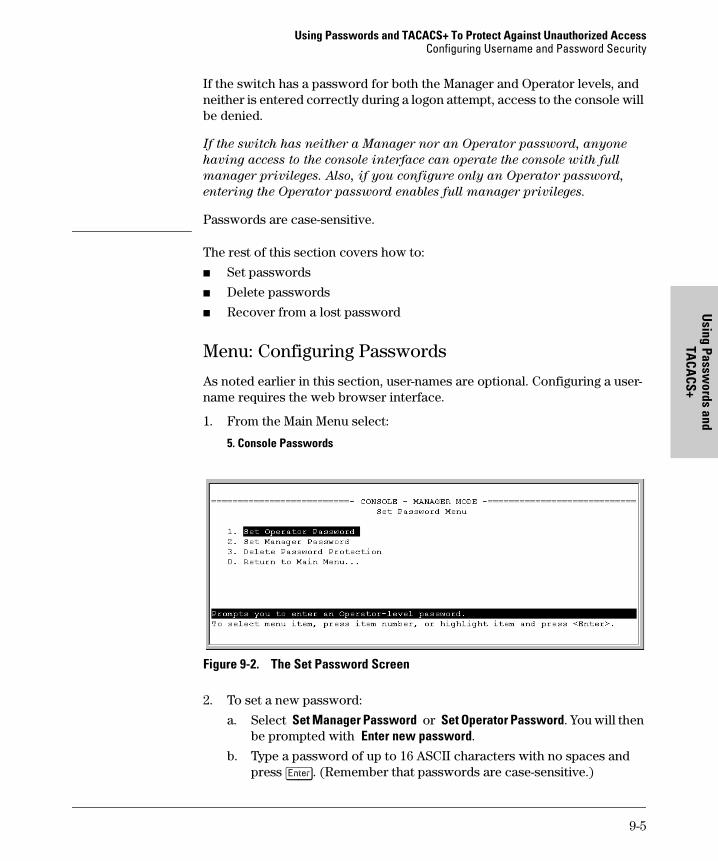
Using Passwords and TACACS+ To Protect Against Unauthorized AccessConfiguring Username and Password Security
Using Passw
ords and TA
CACS+
If the switch has a password for both the Manager and Operator levels, and neither is entered correctly during a logon attempt, access to the console will be denied.
If the switch has neither a Manager nor an Operator password, anyone
having access to the console interface can operate the console with full
manager privileges. Also, if you configure only an Operator password,
entering the Operator password enables full manager privileges.
Passwords are case-sensitive.
The rest of this section covers how to:
� Set passwords
� Delete passwords
� Recover from a lost password
Menu: Configuring Passwords
As noted earlier in this section, user-names are optional. Configuring a user-name requires the web browser interface.
1. From the Main Menu select:
5. Console Passwords
Figure 9-2. The Set Password Screen
2. To set a new password:
a. Select Set Manager Password or Set Operator Password. You will then be prompted with Enter new password.
b. Type a password of up to 16 ASCII characters with no spaces and press [Enter]. (Remember that passwords are case-sensitive.)
9-5
Using Passwords and TACACS+ To Protect Against Unauthorized AccessConfiguring Username and Password Security
Usi
ng P
assw
ords
and
TA
CACS
+
c. When prompted with Enter new password again, retype the new pass-word and press [Enter].
After you configure a password, if you subsequently start a new console session, you will be prompted to enter the password. (If you use the CLI or web browser interface to configure an optional username, the switch will prompt you for the username, and then the password.)
To Delete Password Protection (Including Recovery from a Lost
Password): This procedure deletes all usernames (if configured) and pass-words (Manager and Operator).
If you have physical access to the switch, press and hold the Clear button (on the front of the switch) for a minimum of one second to clear all password protection, then enter new passwords as described earlier in this chapter.
If you do not have physical access to the switch, you will need Manager-Level access:
1. Enter the console at the Manager level.
2. Go to the Set Passwords screen as described above.
3. Select Delete Password Protection. You will then see the following prompt:
Continue Deletion of password protection? No
4. Press the Space bar to select Yes, then press [Enter].
5. Press [Enter] to clear the Password Protection message.
To Recover from a Lost Manager Password: If you cannot start a con-sole session at the Manager level because of a lost Manager password, you can clear the password by getting physical access to the switch and pressing and holding the Clear button for a minimum of one second. This action deletes all passwords and usernames (Manager and Operator) used by both the console and the web browser interface.
CLI: Setting Manager and Operator Passwords
Commands Used in This Section
Configuring Manager and Operator Passwords.
Syntax: password <manager | operator | all>
password See below.
9-6
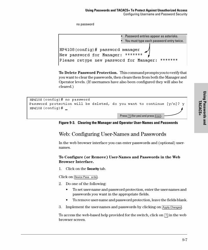
Using Passwords and TACACS+ To Protect Against Unauthorized AccessConfiguring Username and Password Security
Using Passw
ords and TA
CACS+
no password
To Delete Password Protection. This command prompts you to verify that you want to clear the passwords, then clears them from both the Manager and Operator levels. (If usernames have also been configured they will also be cleared.)
Figure 9-3. Clearing the Manager and Operator User-Names and Passwords
Web: Configuring User-Names and Passwords
In the web browser interface you can enter passwords and (optional) user-names.
To Configure (or Remove) User-Names and Passwords in the Web
Browser Interface.
1. Click on the Security tab.
Click on [Device Passwords].
2. Do one of the following:
• To set user-name and password protection, enter the user-names and passwords you want in the appropriate fields.
• To remove user-name and password protection, leave the fields blank.
3. Implement the user-names and passwords by clicking on [Apply Changes].
To access the web-based help provided for the switch, click on [?] in the web browser screen.
• Password entries appear as asterisks.• You must type each password entry twice.
Press [Y] (for yes) and press [Enter].
9-7
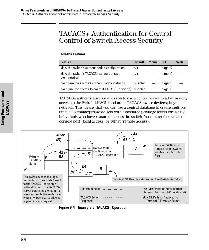
Using Passwords and TACACS+ To Protect Against Unauthorized AccessTACACS+ Authentication for Central Control of Switch Access Security
Usi
ng P
assw
ords
and
TA
CACS
+
TACACS+ Authentication for Central Control of Switch Access Security
TACACS+ Features
TACACS+ authentication enables you to use a central server to allow or deny access to the Switch 4108GL (and other TACACS-aware devices) in your network. This means that you can use a central database to create multiple unique username/password sets with associated privilege levels for use by individuals who have reason to access the switch from either the switch’s console port (local access) or Telnet (remote access).
Figure 9-4. Example of TACACS+ Operation
Feature Default Menu CLI Web
view the switch’s authentication configuration n/a — page 14 —
view the switch’s TACACS+ server contact configuration
n/a — page 15 —
configure the switch’s authentication methods disabled — page 16 —
configure the switch to contact TACACS+ server(s) disabled — page 19 —
B
Switch 4108GL Configured for TACACS+ Operation
Terminal "A" Directly Accessing the Switch Via Switch’s Console Port
Terminal "B" Remotely Accessing The Switch Via Telnet
A
Primary TACACS+ Server
The switch passes the login requests from terminals A and B to the TACACS+ server for authentication. The TACACS+ server determines whether to allow access to the switch and what privilege level to allow for a given access request.
Access Request A1 - A4 : Path for Request from Terminal A (Through Console Port)
TACACS Server B1 - B4: Path for Request from Response Terminal B (Through Telnet)
B1
A2 or B2
A3 or B3
B4
A1A4
9-8
Using Passwords and TACACS+ To Protect Against Unauthorized AccessTACACS+ Authentication for Central Control of Switch Access Security
Using Passw
ords and TA
CACS+
TACACS+ in the Switch 4108GL manages authentication of logon attempts through either the Console port or Telnet. TACACS+ uses an authentication hierarchy consisting of (1) remote passwords assigned in a TACACS+ server and (2) local passwords configured on the switch. That is, with TACACS+ configured, the switch first tries to contact a designated TACACS+ server for authentication services. If the switch fails to connect to any TACACS+ server, it defaults to its own locally assigned passwords for authentication control if it has been configured to do so. For both Console and Telnet access you can configure a login (read-only) and an enable (read/write) privilege level access.
Notes Regarding Sof tware Release G.01 .xx
Software release G.01.xx for the Switch 4108GL enables TACACS+ authenti-cation, which allows or denies access to a Switch 4108GL on the basis of correct username/password pairs managed by the TACACS+ server, and to specify the privilege level to allow if access is granted. This release does not support TACACS+ authorization or accounting services.
In release G.01.xx, TACACS+ does not affect web browser interface access. See "Controlling Web Browser Interface Access" on page 28.
Terminology Used in TACACS Applications:
� NAS (Network Access Server): This is an industry term for a TACACS-aware device that communicates with a TACACS server for authentication services. Some other terms you may see in literature describing TACACS operation are communication server, remote
access server, or terminal server. These terms apply to a Switch 4108GL when TACACS+ is enabled on the switch (that is, when the switch is TACACS-aware).
� TACACS+ Server: The server or management station configured as an access control server for TACACS-enabled devices. To use TACACS+ with the Switch 4108GL and any other TACACS-capable devices in your network, you must purchase, install, and configure a TACACS+ server application on a networked server or management station in the network. The TACACS+ server application you install will provide various options for access control and access notifica-tions. For more on the TACACS+ services available to you, see the documentation provided with the TACACS+ server application you will use.
9-9
Using Passwords and TACACS+ To Protect Against Unauthorized AccessTACACS+ Authentication for Central Control of Switch Access Security
Usi
ng P
assw
ords
and
TA
CACS
+
� Authentication: The process for granting user access to a device through entry of a user name and password and comparison of this username/password pair with previously stored username/password data. Authentication also grants levels of access, depending on the privileges assigned to a user name and password pair by a system administrator.
• Local Authentication: This method uses username/password pairs configured locally on the switch; one pair each for manager-level and operator-level access to the switch. You can assign local usernames and passwords through the CLI or web browser inter-face. (Using the menu interface you can assign a local password, but not a username.) Because this method assigns passwords to the switch instead of to individuals who access the switch, you must distribute the password information on each switch to everyone who needs to access the switch, and you must configure and manage password protection on a per-switch basis. (For more on local authentication, see the password and username information in the Configuration and Management Guide on the Documentation CD-ROM shipped with your Switch 4108GL.
• TACACS+ Authentication: This method enables you to use a TACACS+ server in your network to assign a unique password, user name, and privilege level to each individual or group who needs access to one or more switches or other TACACS-aware devices. This allows you to administer primary authentication from a central server, and to do so with more options than you have when using only local authentication. (You will still need to use use local authentication as a backup if your TACACS+ servers become unavailable.) This means, for example, that you can use a central TACACS+ server to grant, change, or deny access to a specific individual on a specific switch instead of having to change local user name and password assignments on the switch itself, and then have to notify other users of the change.
General System Requirements
To use TACACS+ authentication, you need the following:
� A TACACS+ server application installed and configured on one or more servers or management stations in your network. (There are several TACACS+ software packages available.)
� A switch configured for TACACS+ authentication, with access to one or more TACACS+ servers.
9-10
Using Passwords and TACACS+ To Protect Against Unauthorized AccessTACACS+ Authentication for Central Control of Switch Access Security
Using Passw
ords and TA
CACS+
Notes
The effectiveness of TACACS+ security depends on correctly using your TACACS+ server application. For this reason, HP recommends that you thoroughly test all TACACS+ configurations used in your network.
TACACS-aware HP switches include the capability of configuring multiple backup TACACS+ servers. HP recommends that you use a TACACS+ server application that supports a redundant backup installation. This allows you to configure the switch to use a backup TACACS+ server if it loses access to the first-choice TACACS+ server.
In release G.01.xx, TACACS+ does not affect web browser interface access. See "Controlling Web Browser Interface Access" on page 28.
General Authentication Setup Procedure
It is important to test the TACACS+ service before fully implementing it. Depending on the process and parameter settings you use to set up and test TACACS+ authentication in your network, you could accidentally lock all users, including yourself, out of access to a switch. While recovery is simple, it may pose an inconvenience that can be avoided.To prevent an unintentional lockout on a Switch 4108GL, use a procedure that configures and tests TACACS+ protection for one access type (for example, Telnet access), while keeping the other access type (console, in this case) open in case the Telnet access fails due to a configuration problem. The following procedure outlines a general setup procedure.
Note
If a complete access lockout occurs on the switch as a result of a TACACS+ configuration, see "Troubleshooting TACACS+ Operation" on page “Trouble-shooting TACACS+ Operation” on page 18-13 for recovery methods.
1. Familiarize yourself with the requirements for configuring your TACACS+ server application to respond to requests from a Switch 4108GL. (Refer to the documentation provided with the TACACS+ server software.) This includes knowing whether you need to configure an encryption key. (See “Using the Encryption Key” on page 26.)
9-11
Using Passwords and TACACS+ To Protect Against Unauthorized AccessTACACS+ Authentication for Central Control of Switch Access Security
Usi
ng P
assw
ords
and
TA
CACS
+
2. Determine the following:
3. Plan and enter the TACACS+ server configuration needed to support TACACS+ operation for Telnet access (login and enable) to the switch. This includes the username/password sets for logging in at the Operator (read-only) privilege level and the sets for logging in at the Manager (read/write) privilege level.
Note on Pr iv i lege Levels
When a TACACS+ server authenticates an access request from a switch, it includes a privilege level code for the switch to use in determining which privilege level to grant to the terminal requesting access. The switch interprets a privilege level code of "15" as authorization for the Manager (read/write) privilege level access. Privilege level codes of 14 and lower result in Operator (read-only) access. Thus, when configuring the TACACS+ server response to a request that includes a username/pass-word pair that should have Manager privileges, you must use a privilege level of 15. For more on this topic, refer to the documentation you received with your TACACS+ server application.
If you are a first-time user of the TACACS+ service, HP recommends that you configure only the minimum feature set required by the TACACS+ application to provide service in your network environment. After you have success with the minimum feature set, you may then want to try additional features that the application offers.
� The IP address(es) of the TACACS+ server(s) you want the switch to use for authentication. If you will use more than one server, determine which server is your first-choice for authentication services.
� The encryption key, if any, for allowing the switch to communicate with the server. You can use either a global key or a server-specific key, depending on the encryption config-uration in the TACACS+ server(s).
� The number of log-in attempts you will allow before closing a log-in session. (Default: 3)
� The period you want the switch to wait for a reply to an authentication request before trying another server.
� The username/password pairs you want the TACACS+ server to use for control-ling access to the switch.
� The privilege level you want for each username/password pair administered by the TACACS+ server for controlling access to the switch.
� The username/password pairs you want to use for local authentication (one pair each for Operator and Manager levels).
9-12
Using Passwords and TACACS+ To Protect Against Unauthorized AccessTACACS+ Authentication for Central Control of Switch Access Security
Using Passw
ords and TA
CACS+
4. Ensure that the switch has the correct local username and password for Manager access. (If the switch cannot find any designated TACACS+ servers, the local manager and operator username/password pairs are always used as the secondary access control method.)
Caution
You should ensure that the switch has a local Manager password. Other-wise, if authentication through a TACACS+ server fails for any reason, then unauthorized access will be available through the console port or Telnet.
5. Using a terminal device connected to the switch’s console port, configure the switch for TACACS+ authentication only for telnet login access and telnet enable access. At this stage, do not configure TACACS+ authenti-cation for console access to the switch, as you may need to use the console for access if the configuration for the Telnet method needs debugging.
6. Ensure that the switch is configured to operate on your network and can communicate with your first-choice TACACS+ server. (At a minimum, this requires IP addressing and a successful ping test from the switch to the server.)
7. On a remote terminal device, use Telnet to attempt to access the switch. If the attempt fails, use the console access to check the TACACS+ configuration on the switch. If you make changes in the switch configu-ration, check Telnet access again. If Telnet access still fails, check the configuration in your TACACS+ server application for mis-configura-tions or missing data that could affect the server’s interoperation with the switch.
8. After your testing shows that Telnet access using the TACACS+ server is working properly, configure your TACACS+ server application for console access. Then test the console access. If access problems occur, check for and correct any problems in the switch configuration, and then test console access again. If problems persist, check your TACACS+ server application for mis-configurations or missing data that could affect the console access.
9. When you are confident that TACACS+ access through both Telnet and the switch’s console operates properly, use the write memory command to save the switch’s running-config file to flash.
9-13
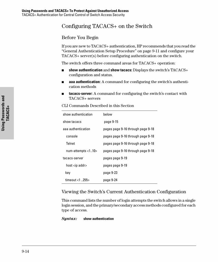
Using Passwords and TACACS+ To Protect Against Unauthorized AccessTACACS+ Authentication for Central Control of Switch Access Security
Usi
ng P
assw
ords
and
TA
CACS
+
Configuring TACACS+ on the Switch
Before You Begin
If you are new to TACACS+ authentication, HP recommends that you read the “General Authentication Setup Procedure” on page 9-11 and configure your TACACS+ server(s) before configuring authentication on the switch.
The switch offers three command areas for TACACS+ operation:
� show authentication and show tacacs: Displays the switch’s TACACS+ configuration and status.
� aaa authentication: A command for configuring the switch’s authenti-cation methods
� tacacs-server: A command for configuring the switch’s contact with TACACS+ servers
CLI Commands Described in this Section
Viewing the Switch’s Current Authentication Configuration
This command lists the number of login attempts the switch allows in a single login session, and the primary/secondary access methods configured for each type of access.
Syntax: show authentication
show authentication below
show tacacs page 9-15
aaa authentication pages page 9-16 through page 9-18
console pages page 9-16 through page 9-18
Telnet pages page 9-16 through page 9-18
num-attempts <1..10> pages page 9-16 through page 9-18
tacacs-server pages page 9-19
host <ip addr> pages page 9-19
key page 9-23
timeout <1 ..255> page 9-24
9-14
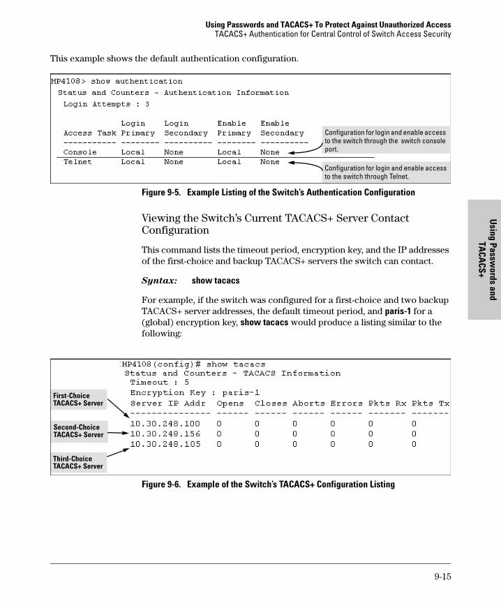
Using Passwords and TACACS+ To Protect Against Unauthorized AccessTACACS+ Authentication for Central Control of Switch Access Security
Using Passw
ords and TA
CACS+
This example shows the default authentication configuration.
Figure 9-5. Example Listing of the Switch’s Authentication Configuration
Viewing the Switch’s Current TACACS+ Server Contact Configuration
This command lists the timeout period, encryption key, and the IP addresses of the first-choice and backup TACACS+ servers the switch can contact.
Syntax: show tacacs
For example, if the switch was configured for a first-choice and two backup TACACS+ server addresses, the default timeout period, and paris-1 for a (global) encryption key, show tacacs would produce a listing similar to the following:
Figure 9-6. Example of the Switch’s TACACS+ Configuration Listing
Configuration for login and enable access to the switch through the switch console port.
Configuration for login and enable access to the switch through Telnet.
First-Choice TACACS+ Server
Second-Choice TACACS+ Server
Third-Choice TACACS+ Server
9-15
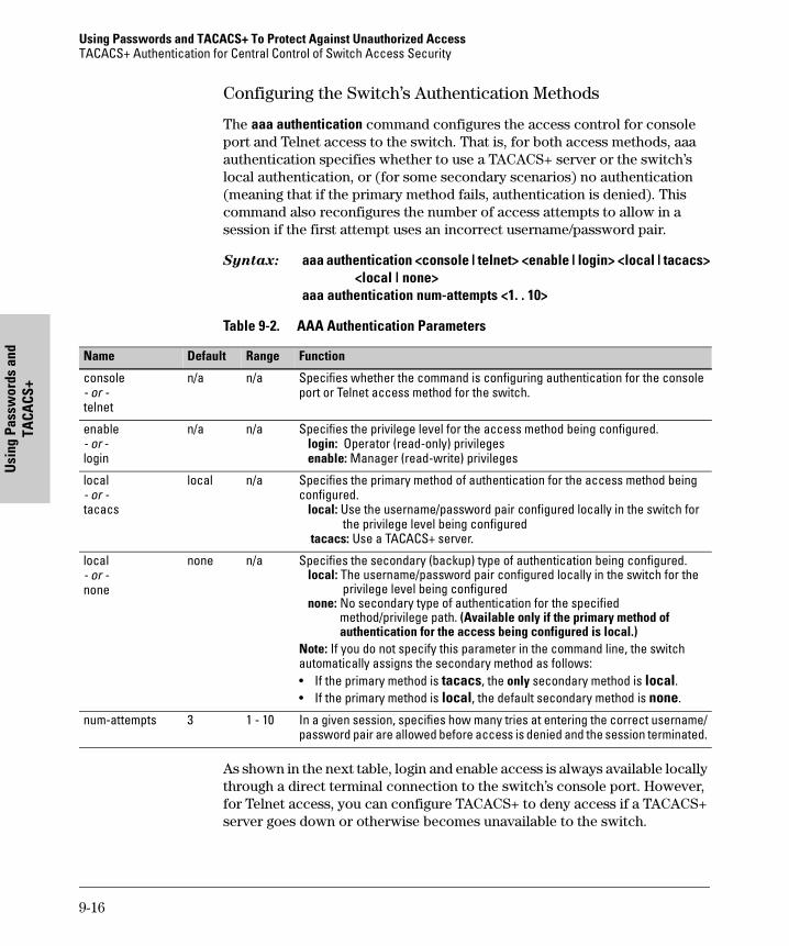
Using Passwords and TACACS+ To Protect Against Unauthorized AccessTACACS+ Authentication for Central Control of Switch Access Security
Usi
ng P
assw
ords
and
TA
CACS
+
Configuring the Switch’s Authentication Methods
The aaa authentication command configures the access control for console port and Telnet access to the switch. That is, for both access methods, aaa authentication specifies whether to use a TACACS+ server or the switch’s local authentication, or (for some secondary scenarios) no authentication (meaning that if the primary method fails, authentication is denied). This command also reconfigures the number of access attempts to allow in a session if the first attempt uses an incorrect username/password pair.
Syntax: aaa authentication <console | telnet> <enable | login> <local | tacacs><local | none>
aaa authentication num-attempts <1. . 10>
Table 9-2. AAA Authentication Parameters
As shown in the next table, login and enable access is always available locally through a direct terminal connection to the switch’s console port. However, for Telnet access, you can configure TACACS+ to deny access if a TACACS+ server goes down or otherwise becomes unavailable to the switch.
Name Default Range Function
console- or -telnet
n/a n/a Specifies whether the command is configuring authentication for the console port or Telnet access method for the switch.
enable- or -login
n/a n/a Specifies the privilege level for the access method being configured. login: Operator (read-only) privileges enable: Manager (read-write) privileges
local- or -tacacs
local n/a Specifies the primary method of authentication for the access method being configured. local: Use the username/password pair configured locally in the switch for the privilege level being configured tacacs: Use a TACACS+ server.
local- or -none
none n/a Specifies the secondary (backup) type of authentication being configured. local: The username/password pair configured locally in the switch for the privilege level being configured none: No secondary type of authentication for the specified method/privilege path. (Available only if the primary method of authentication for the access being configured is local.)Note: If you do not specify this parameter in the command line, the switch automatically assigns the secondary method as follows:• If the primary method is tacacs, the only secondary method is local.• If the primary method is local, the default secondary method is none.
num-attempts 3 1 - 10 In a given session, specifies how many tries at entering the correct username/password pair are allowed before access is denied and the session terminated.
9-16
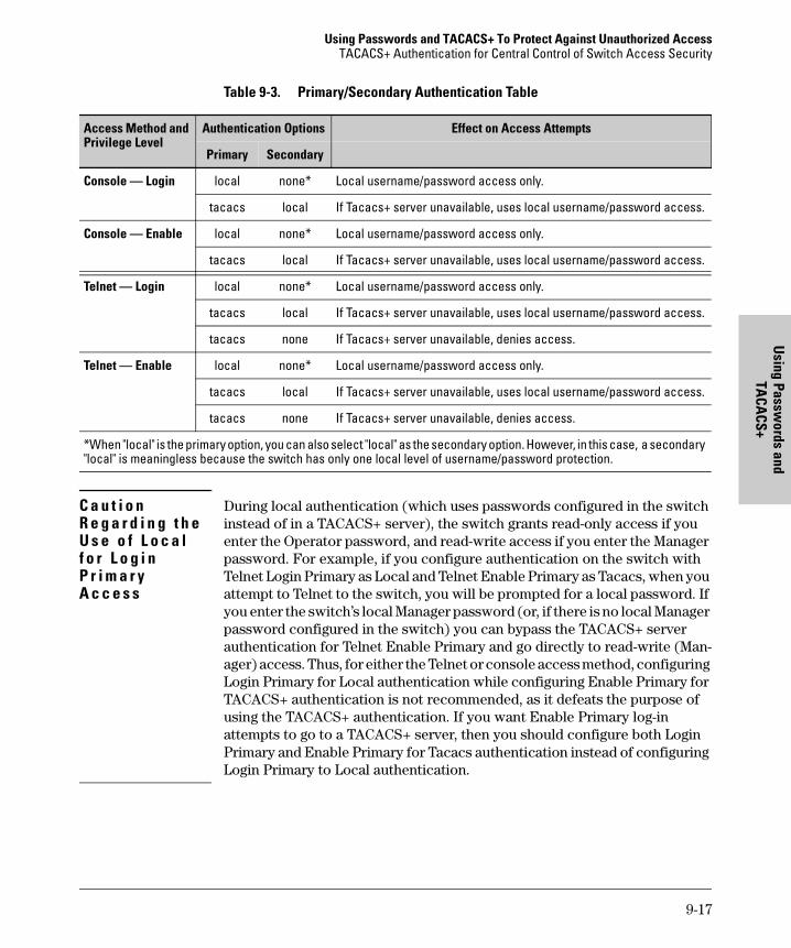
Using Passwords and TACACS+ To Protect Against Unauthorized AccessTACACS+ Authentication for Central Control of Switch Access Security
Using Passw
ords and TA
CACS+
Table 9-3. Primary/Secondary Authentication Table
C a u t i o n R e g a r d i n g t h e U s e o f L o c a l f o r L o g i n P r i m a r y A c c e s s
During local authentication (which uses passwords configured in the switch instead of in a TACACS+ server), the switch grants read-only access if you enter the Operator password, and read-write access if you enter the Manager password. For example, if you configure authentication on the switch with Telnet Login Primary as Local and Telnet Enable Primary as Tacacs, when you attempt to Telnet to the switch, you will be prompted for a local password. If you enter the switch’s local Manager password (or, if there is no local Manager password configured in the switch) you can bypass the TACACS+ server authentication for Telnet Enable Primary and go directly to read-write (Man-ager) access. Thus, for either the Telnet or console access method, configuring Login Primary for Local authentication while configuring Enable Primary for TACACS+ authentication is not recommended, as it defeats the purpose of using the TACACS+ authentication. If you want Enable Primary log-in attempts to go to a TACACS+ server, then you should configure both Login Primary and Enable Primary for Tacacs authentication instead of configuring Login Primary to Local authentication.
Access Method and Privilege Level
Authentication Options Effect on Access Attempts
Primary Secondary
Console — Login local none* Local username/password access only.
tacacs local If Tacacs+ server unavailable, uses local username/password access.
Console — Enable local none* Local username/password access only.
tacacs local If Tacacs+ server unavailable, uses local username/password access.
Telnet — Login local none* Local username/password access only.
tacacs local If Tacacs+ server unavailable, uses local username/password access.
tacacs none If Tacacs+ server unavailable, denies access.
Telnet — Enable local none* Local username/password access only.
tacacs local If Tacacs+ server unavailable, uses local username/password access.
tacacs none If Tacacs+ server unavailable, denies access.
*When "local" is the primary option, you can also select "local" as the secondary option. However, in this case, a secondary "local" is meaningless because the switch has only one local level of username/password protection.
9-17
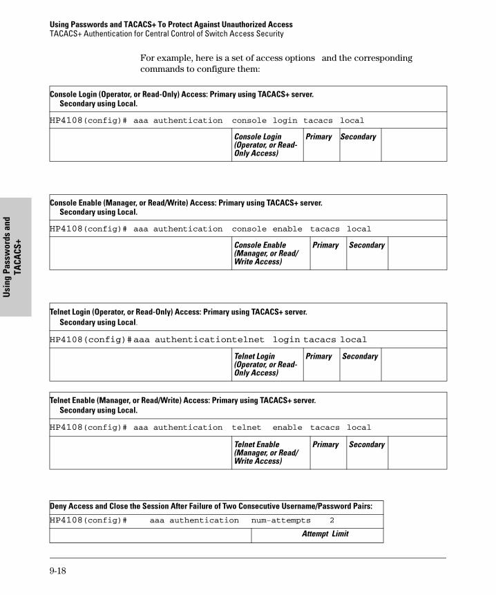
Using Passwords and TACACS+ To Protect Against Unauthorized AccessTACACS+ Authentication for Central Control of Switch Access Security
Usi
ng P
assw
ords
and
TA
CACS
+
For example, here is a set of access options and the corresponding commands to configure them:
Console Login (Operator, or Read-Only) Access: Primary using TACACS+ server.Secondary using Local.
HP4108(config)# aaa authentication console login tacacs local
Console Login (Operator, or Read- Only Access)
Primary Secondary
Console Enable (Manager, or Read/Write) Access: Primary using TACACS+ server.Secondary using Local.
HP4108(config)# aaa authentication console enable tacacs local
Console Enable (Manager, or Read/ Write Access)
Primary
Secondary
Telnet Login (Operator, or Read-Only) Access: Primary using TACACS+ server.Secondary using Local.
HP4108(config)#aaa authenticationtelnet login tacacs local
Telnet Login (Operator, or Read- Only Access)
Primary
Secondary
Telnet Enable (Manager, or Read/Write) Access: Primary using TACACS+ server.Secondary using Local.
HP4108(config)# aaa authentication telnet enable tacacs local
Telnet Enable (Manager, or Read/ Write Access)
Primary
Secondary
Deny Access and Close the Session After Failure of Two Consecutive Username/Password Pairs:
HP4108(config)# aaa authentication num-attempts 2
Attempt Limit
9-18
Using Passwords and TACACS+ To Protect Against Unauthorized AccessTACACS+ Authentication for Central Control of Switch Access Security
Using Passw
ords and TA
CACS+
Configuring the Switch’s TACACS+ Server Access
The tacacs-server command configures these parameters:
� The host IP address(es) for up to three TACACS+ servers; one first-choice and up to two backups. Designating backup servers provides for a continuation of authentication services in case the switch is unable to contact the first-choice server.
� An optional encryption key. This key helps to improve security, and must match the encryption key used in your TACACS+ server appli-cation. In some applications, the term "secret key" or "secret" may be used instead of "encryption key". If you need only one encryption key for the switch to use in all attempts to authenticate through a TACACS+ server, configure a global key. However, if the switch is configured to access multiple TACACS+ servers having different encryption keys, you can configure the switch to use different encryp-tion keys for different TACACS+ servers.
� The timeout value in seconds for attempts to contact a TACACS+ server. If the switch sends an authentication request, but does not receive a response within the period specified by the timeout value, the switch resends the request to the next server in its Server IP Addr list, if any. If the switch still fails to receive a response from any TACACS+ server, it reverts to whatever secondary authentication method was configured using the aaa authentication command (local or none; see “Configuring the Switch’s Authentication Methods” on page 16.)
N o t e As described under “General Authentication Setup Procedure” on page 9-11, HP recommends that you configure, test, and troubleshoot authentication via Telnet access before you configure authentication via console port access. This helps to prevent accidentally locking yourself out of switch access due to errors or problems in setting up authentication in either the switch or your TACACS+ server.
9-19
Using Passwords and TACACS+ To Protect Against Unauthorized AccessTACACS+ Authentication for Central Control of Switch Access Security
Usi
ng P
assw
ords
and
TA
CACS
+
Syntax:tacacs-server host <ip-addr> Adds a TACACS+ server and optionally[key <key-string>] assigns a server-specific encryption key.
[no] tacacs-server host <ip-addr> Removes a TACACS+ server assignment (including its server-specific encryption key, if any).
tacacs-server key <key-string> Enters the optional global encryption key.[no] tacacs-server key Removes the optional global encryption
key. (Does not affect any server-specificencryption key assignments.)
tacacs-server timeout <1 . . 255> Changes the wait period for a TACACSserver response. (Default: 5 seconds.)
N o t e o n E n c r y p t i o n K e ys
Encryption keys configured in the switch must exactly match the encryption keys configured in TACACS+ servers the switch will attempt to use for authentication.
If you configure a global encryption key, the switch uses it only with servers for which you have not also configured a server-specific key. Thus, a global key is more useful where the TACACS+ servers you are using all have an identical key, and server-specific keys are necessary where different TACACS+ servers have different keys.
If TACACS+ server “X” does not have an encryption key assigned for the switch, then configuring either a global encryption key or a server-specific key in the switch for server “X” will block authentication support from server “X”.
9-20
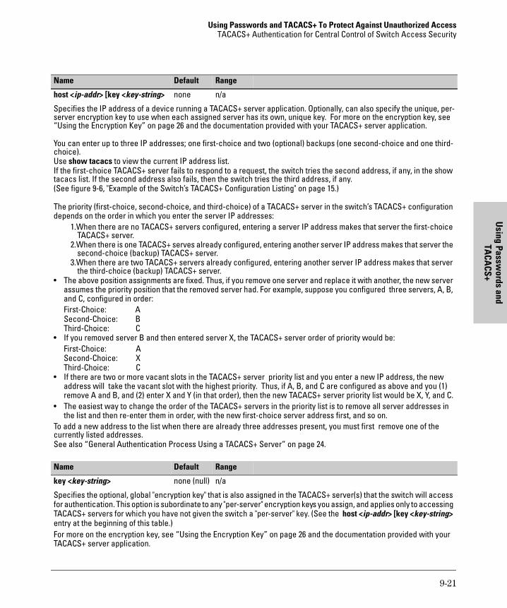
Using Passwords and TACACS+ To Protect Against Unauthorized AccessTACACS+ Authentication for Central Control of Switch Access Security
Using Passw
ords and TA
CACS+
Name Default Range
host <ip-addr> [key <key-string> none n/a
Specifies the IP address of a device running a TACACS+ server application. Optionally, can also specify the unique, per-server encryption key to use when each assigned server has its own, unique key. For more on the encryption key, see “Using the Encryption Key” on page 26 and the documentation provided with your TACACS+ server application.
You can enter up to three IP addresses; one first-choice and two (optional) backups (one second-choice and one third-choice). Use show tacacs to view the current IP address list. If the first-choice TACACS+ server fails to respond to a request, the switch tries the second address, if any, in the show tacacs list. If the second address also fails, then the switch tries the third address, if any. (See figure 9-6, "Example of the Switch’s TACACS+ Configuration Listing" on page 15.)
The priority (first-choice, second-choice, and third-choice) of a TACACS+ server in the switch’s TACACS+ configuration depends on the order in which you enter the server IP addresses:
1.When there are no TACACS+ servers configured, entering a server IP address makes that server the first-choice TACACS+ server.
2.When there is one TACACS+ serves already configured, entering another server IP address makes that server the second-choice (backup) TACACS+ server.
3.When there are two TACACS+ servers already configured, entering another server IP address makes that server the third-choice (backup) TACACS+ server.
• The above position assignments are fixed. Thus, if you remove one server and replace it with another, the new server assumes the priority position that the removed server had. For example, suppose you configured three servers, A, B, and C, configured in order:First-Choice: ASecond-Choice: BThird-Choice: C
• If you removed server B and then entered server X, the TACACS+ server order of priority would be:First-Choice: ASecond-Choice: XThird-Choice: C
• If there are two or more vacant slots in the TACACS+ server priority list and you enter a new IP address, the new address will take the vacant slot with the highest priority. Thus, if A, B, and C are configured as above and you (1) remove A and B, and (2) enter X and Y (in that order), then the new TACACS+ server priority list would be X, Y, and C.
• The easiest way to change the order of the TACACS+ servers in the priority list is to remove all server addresses in the list and then re-enter them in order, with the new first-choice server address first, and so on.
To add a new address to the list when there are already three addresses present, you must first remove one of the currently listed addresses.See also “General Authentication Process Using a TACACS+ Server” on page 24.
Name Default Range
key <key-string> none (null) n/a
Specifies the optional, global "encryption key" that is also assigned in the TACACS+ server(s) that the switch will access for authentication. This option is subordinate to any "per-server" encryption keys you assign, and applies only to accessing TACACS+ servers for which you have not given the switch a "per-server" key. (See the host <ip-addr> [key <key-string> entry at the beginning of this table.) For more on the encryption key, see “Using the Encryption Key” on page 26 and the documentation provided with your TACACS+ server application.
9-21
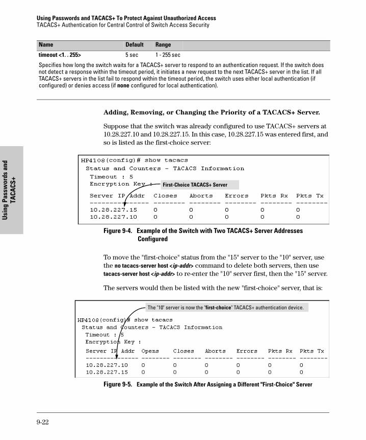
Using Passwords and TACACS+ To Protect Against Unauthorized AccessTACACS+ Authentication for Central Control of Switch Access Security
Usi
ng P
assw
ords
and
TA
CACS
+
Adding, Removing, or Changing the Priority of a TACACS+ Server.
Suppose that the switch was already configured to use TACACS+ servers at 10.28.227.10 and 10.28.227.15. In this case, 10.28.227.15 was entered first, and so is listed as the first-choice server:
Figure 9-4. Example of the Switch with Two TACACS+ Server Addresses Configured
To move the "first-choice" status from the "15" server to the "10" server, use the no tacacs-server host <ip-addr> command to delete both servers, then use tacacs-server host <ip-addr> to re-enter the "10" server first, then the "15" server.
The servers would then be listed with the new "first-choice" server, that is:
Figure 9-5. Example of the Switch After Assigning a Different "First-Choice" Server
timeout <1. . 255> 5 sec 1 - 255 sec
Specifies how long the switch waits for a TACACS+ server to respond to an authentication request. If the switch does not detect a response within the timeout period, it initiates a new request to the next TACACS+ server in the list. If all TACACS+ servers in the list fail to respond within the timeout period, the switch uses either local authentication (if configured) or denies access (if none configured for local authentication).
Name Default Range
First-Choice TACACS+ Server
The "10" server is now the "first-choice" TACACS+ authentication device.
9-22
Using Passwords and TACACS+ To Protect Against Unauthorized AccessTACACS+ Authentication for Central Control of Switch Access Security
Using Passw
ords and TA
CACS+
To remove the 10.28.227.15 device as a TACACS+ server, you would use this command:
HP4108(config)# no tacacs-server host 10.28.227.15
Configuring an Encryption Key. Use an encryption key in the switch if the switch will be requesting authentication from a TACACS+ server that also uses an encryption key. (If the server expects a key, but the switch either does not provide one, or provides an incorrect key, then the authentication attempt will fail.) Use a global encryption key if the same key applies to all TACACS+ servers the switch may use for authentication attempts. Use a per-server
encryption key if different servers the switch may use will have different keys. (For more details on encryption keys, see “Using the Encryption Key” on page 26.)
To configure north01 as a global encryption key:
HP4108(config) tacacs-server key north01
To configure north01 as a per-server encryption key:
HP4108(config)tacacs-server host 10.28.227.63 key north01
An encryption key can contain up to 100 characters, without spaces, and is likely to be case-sensitive in most TACACS+ server applications.
To delete a global encryption key from the switch, use this command:
HP4108(config)# no tacacs-server key
To delete a per-server encryption key in the switch, re-enter the tacacs-server host command without the key parameter. For example, if you have north01 configured as the encryption key for a TACACS+ server with the IP address of 10.28.227.104 and you wanted to eliminate the key, you would use this command:
HP4108(config)# tacacs-server host 10.28.227.104
Note
The show tacacs command lists the global encryption key, if configured. However, to view any configured per-server encryption keys, you must use show config or show config running (if you have made TACACS+ configuration changes without executing write mem).
9-23
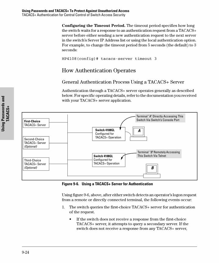
Using Passwords and TACACS+ To Protect Against Unauthorized AccessTACACS+ Authentication for Central Control of Switch Access Security
Usi
ng P
assw
ords
and
TA
CACS
+
Configuring the Timeout Period. The timeout period specifies how long the switch waits for a response to an authentication request from a TACACS+ server before either sending a new authentication request to the next server in the switch’s Server IP Address list or using the local authentication option. For example, to change the timeout period from 5 seconds (the default) to 3 seconds:
HP4108(config)# tacacs-server timeout 3
How Authentication Operates
General Authentication Process Using a TACACS+ Server
Authentication through a TACACS+ server operates generally as described below. For specific operating details, refer to the documentation you received with your TACACS+ server application.
Figure 9-6. Using a TACACS+ Server for Authentication
Using figure 9-6, above, after either switch detects an operator’s logon request from a remote or directly connected terminal, the following events occur:
1. The switch queries the first-choice TACACS+ server for authentication of the request.
• If the switch does not receive a response from the first-choice TACACS+ server, it attempts to query a secondary server. If the switch does not receive a response from any TACACS+ server,
Switch 4108GL Configured for TACACS+ Operation
First-Choice TACACS+ Server
B
Switch 4108GL Configured for TACACS+ Operation
Terminal "A" Directly Accessing This Switch Via Switch’s Console Port
Terminal "B" Remotely Accessing This Switch Via Telnet
A
Second-Choice TACACS+ Server(Optional)
Third-Choice TACACS+ Server(Optional)
9-24
Using Passwords and TACACS+ To Protect Against Unauthorized AccessTACACS+ Authentication for Central Control of Switch Access Security
Using Passw
ords and TA
CACS+
then it uses its own local username/password pairs to authenti-cate the logon request. (See "Local Authentication Process", on page 25.)
• If a TACACS+ server recognizes the switch, it forwards a user-name prompt to the requesting terminal via the switch.
2. When the requesting terminal responds to the prompt with a username, the switch forwards it to the TACACS+ server.
3. After the server receives the username input, the requesting terminal receives a password prompt from the server via the switch.
4. When the requesting terminal responds to the prompt with a password, the switch forwards it to the TACACS+ server and one of the following actions occurs:
• If the username/password pair received from the requesting terminal matches a username/password pair previously stored in the server, then the server passes access permission through the switch to the terminal.
• If the username/password pair entered at the requesting terminal does not match a username/password pair previously stored in the server, access is denied. In this case, the terminal is again prompted to enter a username and repeat steps 2 through 4. In the default configuration, the switch allows up to three attempts to authenticate a login session. If the requesting terminal exhausts the attempt limit without a successful TACACS+ authentication, the login session is terminated and the operator at the requesting terminal must initiate a new session before trying again.
Local Authentication Process
When the switch is configured to use TACACS+, it reverts to local authentica-tion only if one of these two conditions exists:
� "Local" is the authentication option for the access method being used.
� TACACS+ is the primary authentication mode for the access method being used. However, the switch was unable to connect to any TACACS+ servers (or no servers were configured) AND Local is the secondary authentication mode being used.
(For a listing of authentication options, see Table 3 on page 17.)
9-25
Using Passwords and TACACS+ To Protect Against Unauthorized AccessTACACS+ Authentication for Central Control of Switch Access Security
Usi
ng P
assw
ords
and
TA
CACS
+
For local authentication, the switch uses the operator-level and manager-level username/password set(s) previously configured locally on the switch. (These are the usernames and passwords you can configure using the CLI password command, the web browser interface, or the menu interface—which enables only local password configuration).
� If the operator at the requesting terminal correctly enters the user-name/password pair for either access level, access is granted.
� If the username/password pair entered at the requesting terminal does not match either username/password pair previously configured locally in the switch, access is denied. In this case, the terminal is again prompted to enter a username/password pair. In the default configuration, the switch allows up to three attempts. If the requesting terminal exhausts the attempt limit without a successful authentica-tion, the login session is terminated and the operator at the requesting terminal must initiate a new session before trying again.
Note The switch’s menu allows you to configure only the local Operator and Manager passwords, and not any usernames. In this case, all prompts for local authentication will request only a local password. However, if you use the CLI or the web browser interface to configure usernames for local access, you will see a prompt for both a local username and a local password during local authentication.
Using the Encryption Key
General Operation
When used, the encryption key (sometimes termed "key", "secret key", or "secret") helps to prevent unauthorized intruders on the network from reading username and password information in TACACS+ packets moving between the switch and a TACACS+ server. At the TACACS+ server, a key may include both of the following:
� Global key: A general key assignment in the TACACS+ server appli-cation that applies to all TACACS-aware devices for which an indi-vidual key has not been configured.
� Server-Specific key: A unique key assignment in the TACACS+ server application that applies to a specific TACACS-aware device.
9-26
Using Passwords and TACACS+ To Protect Against Unauthorized AccessTACACS+ Authentication for Central Control of Switch Access Security
Using Passw
ords and TA
CACS+
N o t e Configure a key in the switch only if the TACACS+ server application has this exact same key configured for the switch. That is, if the key parameter in switch "X" does not exactly match the key setting for switch "X" in the TACACS+ server application, then communication between the switch and the TACACS+ server will fail.
Thus, on the TACACS+ server side, you have a choice as to how to implement a key. On the switch side, it is necessary only to enter the key parameter so that it exactly matches its counterpart in the server. For information on how to configure a general or individual key in the TACACS+ server, refer to the documentation you received with the application.
Encryption Options in the Switch
When configured, the encryption key causes the switch to encrypt the TACACS+ packets it sends to the server. When left at "null", the TACACS+ packets are sent in clear text. The encryption key (or just "key") you configure in the switch must be identical to the encryption key configured in the corresponding TACACS+ server. If the key is the same for all TACACS+ servers the switch will use for authentication, then configure a global key in the switch. If the key is different for one or more of these servers, use "server-specific" keys in the switch. (If you configure both a global key and one or more per-server keys, the per-server keys will override the global key for the specified servers.)
For example, you would use the next command to configure a global encryp-tion key in the switch to match a key entered as north40campus in two target TACACS+ servers. (That is, both servers use the same key for your switch.) Note that you do not need the server IP addresses to configure a global key in the switch:
HP4108(config)# tacacs-server key north40campus
Suppose that you subsequently add a third TACACS+ server (with an IP address of 10.28.227.87) that has south10campus for an encryption key. Because this key is different than the one used for the two servers in the previous example, you will need to assign a server-specific key in the switch that applies only to the designated server:
HP4108(config)# tacacs-server host 10.28.227.87 key
south10campus
With both of the above keys configured in the switch, the south10campus key overrides the north40campus key only when the switch tries to access the TACACS+ server having the 10.28.227.87 address.
9-27
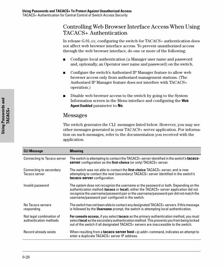
Using Passwords and TACACS+ To Protect Against Unauthorized AccessTACACS+ Authentication for Central Control of Switch Access Security
Usi
ng P
assw
ords
and
TA
CACS
+
Controlling Web Browser Interface Access When Using TACACS+ AuthenticationIn release G.01.xx, configuring the switch for TACACS+ authentication does not affect web browser interface access. To prevent unauthorized access through the web browser interface, do one or more of the following:
� Configure local authentication (a Manager user name and password and, optionally, an Operator user name and password) on the switch.
� Configure the switch’s Authorized IP Manager feature to allow web browser access only from authorized management stations. (The Authorized IP Manager feature does not interfere with TACACS+ operation.)
� Disable web browser access to the switch by going to the System Information screen in the Menu interface and configuring the Web Agent Enabled parameter to No.
Messages
The switch generates the CLI messages listed below. However, you may see other messages generated in your TACACS+ server application. For informa-tion on such messages, refer to the documentation you received with the application.
CLI Message Meaning
Connecting to Tacacs server The switch is attempting to contact the TACACS+ server identified in the switch’s tacacs-server configuration as the first-choice (or only) TACACS+ server.
Connecting to secondary Tacacs server
The switch was not able to contact the first-choice TACACS+ server, and is now attempting to contact the next (secondary) TACACS+ server identified in the switch’s tacacs-server configuration.
Invalid password The system does not recognize the username or the password or both. Depending on the authentication method (tacacs or local), either the TACACS+ server application did not recognize the username/password pair or the username/password pair did not match the username/password pair configured in the switch.
No Tacacs servers responding
The switch has not been able to contact any designated TACACS+ servers. If this message is followed by the Username prompt, the switch is attempting local authentication.
Not legal combination of authentication methods
For console access, if you select tacacs as the primary authentication method, you must select local as the secondary authentication method. This prevents you from being locked out of the switch if all designated TACACS+ servers are inaccessible to the switch.
Record already exists When resulting from a tacacs-server host <ip addr> command, indicates an attempt to enter a duplicate TACACS+ server IP address.
9-28
Using Passwords and TACACS+ To Protect Against Unauthorized AccessTACACS+ Authentication for Central Control of Switch Access Security
Using Passw
ords and TA
CACS+
Operating Notes
� If you configure Authorized IP Managers on the switch, it is not necessary to include any devices used as TACACS+ servers in the authorized manager list. That is, authentication traffic between a TACACS+ server and the switch is not subject to Authorized IP Manager controls configured on the switch. Also, the switch does not attempt TACACS+ authentication for a management station that the Authorized IP Manager list excludes because, independent of TACACS+, the switch already denies access to such stations.
� When TACACS+ is not enabled on the switch—or when the switch’s only designated TACACS+ servers are not accessible— setting a local
Operator password without also setting a local Manager password
does not protect the switch from manager-level access by unautho-
rized persons.)
Troubleshooting TACACS+ Operation
Event Log. When troubleshooting TACACS+ operation, check the switch’s Event Log for indications of problem areas.
For specific troubleshooting help, see “TACACS-Related Problems” on page 18-9.
9-29

Using Passwords and TACACS+ To Protect Against Unauthorized AccessTACACS+ Authentication for Central Control of Switch Access Security
Usi
ng P
assw
ords
and
TA
CACS
+
9-30
Using A
uthorize IP M
anagers
10
Using Authorized IP Managers for Increased Management Security
Chapter Contents
Overview . . . . . . . . . . . . . . . . . . . . . . . . . . . . . . . . . . . . . . . . . . . . . . . . . . . . . 10-2
Using Authorized IP Managers . . . . . . . . . . . . . . . . . . . . . . . . . . . . . . . . . . 10-4
Access Levels . . . . . . . . . . . . . . . . . . . . . . . . . . . . . . . . . . . . . . . . . . . . . . 10-5
Defining Authorized Management Stations . . . . . . . . . . . . . . . . . . . . . 10-5Overview of IP Mask Operation . . . . . . . . . . . . . . . . . . . . . . . . . . . 10-5
Menu: Viewing and Configuring IP Authorized Managers . . . . . . . . . 10-7
CLI: Viewing and Configuring Authorized IP Managers . . . . . . . . . . . 10-8Listing the Switch’s Current Authorized IP Manager(s) . . . . . . . 10-8Configuring IP Authorized Managers for the Switch . . . . . . . . . . 10-9
Web: Configuring IP Authorized Managers . . . . . . . . . . . . . . . . . . . . 10-10
Building IP Masks . . . . . . . . . . . . . . . . . . . . . . . . . . . . . . . . . . . . . . . . . 10-10Configuring One Station Per Authorized Manager IP Entry . . . 10-10Configuring Multiple Stations Per Authorized Manager IP Entry . . . . . . . . . . . . . . . . . . . . . . . . . . . . . . . . . . . . . . 10-11Additional Examples for Authorizing Multiple Stations . . . . . . 10-13
Operating and Troubleshooting Notes . . . . . . . . . . . . . . . . . . . . . . . . 10-13
10-1
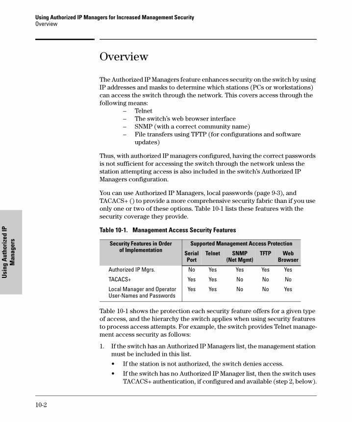
Using Authorized IP Managers for Increased Management SecurityOverview
Usi
ng A
utho
rize
d IP
M
anag
ers
Overview
The Authorized IP Managers feature enhances security on the switch by using IP addresses and masks to determine which stations (PCs or workstations) can access the switch through the network. This covers access through the following means:
– Telnet– The switch’s web browser interface – SNMP (with a correct community name)– File transfers using TFTP (for configurations and software
updates)
Thus, with authorized IP managers configured, having the correct passwords is not sufficient for accessing the switch through the network unless the station attempting access is also included in the switch’s Authorized IP Managers configuration.
You can use Authorized IP Managers, local passwords (page 9-3), and TACACS+ () to provide a more comprehensive security fabric than if you use only one or two of these options. Table 10-1 lists these features with the security coverage they provide.
Table 10-1. Management Access Security Features
Table 10-1 shows the protection each security feature offers for a given type of access, and the hierarchy the switch applies when using security features to process access attempts. For example, the switch provides Telnet manage-ment access security as follows:
1. If the switch has an Authorized IP Managers list, the management station must be included in this list.
• If the station is not authorized, the switch denies access.
• If the switch has no Authorized IP Manager list, then the switch uses TACACS+ authentication, if configured and available (step 2, below).
Security Features in Orderof Implementation
Supported Management Access Protection
Serial Port
Telnet SNMP(Net Mgmt)
TFTP Web Browser
Authorized IP Mgrs. No Yes Yes Yes Yes
TACACS+ Yes Yes No No No
Local Manager and Operator User-Names and Passwords
Yes Yes No No Yes
10-2
Using Authorized IP Managers for Increased Management SecurityOverview
Using A
uthorized IP M
anagers
2. If TACACS+ is configured and a TACACS+ server issues a prompt, the correct passwords must be entered from the management station and verified by the TACACS+ server.
• If incorrect passwords are entered, the TACACS+ server denies access to the switch.
• If TACACS+ is not configured or the TACACS+ server is not accessi-ble, the switch uses local user-name/password protection (step 3, below).
3. If local user-name/password protection is configured, the correct user-name and password must be entered.
• If incorrect passwords are entered, the switch denies access.
• If a manager password is not configured, the switch allows manager-level (read/write) access.
The preceding information outlines general access security. To understand the options offered by each security feature, refer to the following.
� "Using Authorized IP Managers" (this chapter)
� page 9-3: “Configuring Username and Password Security”
� page 9-8: “TACACS+ Authentication for Central Control of Switch Access Security”
10-3
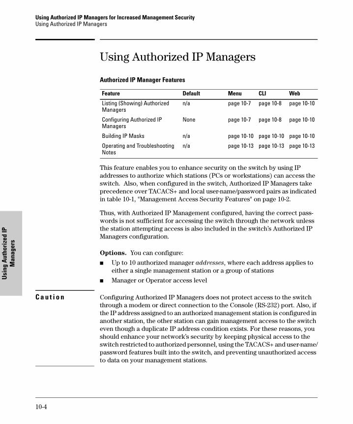
Using Authorized IP Managers for Increased Management SecurityUsing Authorized IP Managers
Usi
ng A
utho
rize
d IP
M
anag
ers
Using Authorized IP Managers
Authorized IP Manager Features
This feature enables you to enhance security on the switch by using IP addresses to authorize which stations (PCs or workstations) can access the switch. Also, when configured in the switch, Authorized IP Managers take precedence over TACACS+ and local user-name/password pairs as indicated in table 10-1, "Management Access Security Features" on page 10-2.
Thus, with Authorized IP Management configured, having the correct pass-words is not sufficient for accessing the switch through the network unless the station attempting access is also included in the switch’s Authorized IP Managers configuration.
Options. You can configure:
� Up to 10 authorized manager addresses, where each address applies to either a single management station or a group of stations
� Manager or Operator access level
C a u t i o n Configuring Authorized IP Managers does not protect access to the switch through a modem or direct connection to the Console (RS-232) port. Also, if the IP address assigned to an authorized management station is configured in another station, the other station can gain management access to the switch even though a duplicate IP address condition exists. For these reasons, you should enhance your network’s security by keeping physical access to the switch restricted to authorized personnel, using the TACACS+ and user-name/password features built into the switch, and preventing unauthorized access to data on your management stations.
Feature Default Menu CLI Web
Listing (Showing) Authorized Managers
n/a page 10-7 page 10-8 page 10-10
Configuring Authorized IP Managers
None page 10-7 page 10-8 page 10-10
Building IP Masks n/a page 10-10 page 10-10 page 10-10
Operating and Troubleshooting Notes
n/a page 10-13 page 10-13 page 10-13
10-4
Using Authorized IP Managers for Increased Management SecurityUsing Authorized IP Managers
Using A
uthorized IP M
anagers
Access Levels
For each authorized manager address, you can configure either of these access levels:
� Manager: Enables full access to all web browser and console interface screens for viewing, configuration, and all other operations available in these interfaces.
� Operator: Allows read-only access from the web browser and console interfaces. (This is the same access that is allowed by the switch’s opera-tor-level password feature.)
Defining Authorized Management Stations
� Authorizing Single Stations: The table entry authorizes a single man-agement station to have IP access to the switch. To use this method, just enter the IP address of an authorized management station in the Autho-rized Manager IP column, and leave the IP Mask set to 255.255.255.255. This is the easiest way to use the Authorized Managers feature. (For more on this topic, see “Configuring One Station Per Authorized Manager IP Entry” on page 10-10.)
� Authorizing Multiple Stations: The table entry uses the IP Mask to authorize access to the switch from a defined group of stations. This is useful if you want to easily authorize several stations to have access to the switch without having to type in an entry for every station. All stations in the group defined by the one Authorized Manager IP table entry and its associated IP mask will have the same access level—Manager or Operator. (For more on this topic, see “Configuring Multiple Stations Per Authorized Manager IP Entry” on page 10-11.)
To configure the switch for authorized manager access, enter the appropriate Authorized Manager IP value, specify an IP Mask, and select either Manager or Operator for the Access Level. The IP Mask determines how the Authorized Manager IP value is used to allow or deny access to the switch by a manage-ment station.
Overview of IP Mask Operation
The default IP Mask is 255.255.255.255 and allows switch access only to a station having an IP address that is identical to the Authorized Manager IP parameter value. (“255” in an octet of the mask means that only the exact value in the corresponding octet of the Authorized Manager IP parameter is allowed in the IP address of an authorized management station.) However, you can alter the mask and the Authorized Manager IP parameter to specify ranges of
10-5
Using Authorized IP Managers for Increased Management SecurityUsing Authorized IP Managers
Usi
ng A
utho
rize
d IP
M
anag
ers
authorized IP addresses. For example, a mask of 255.255.255.0 and any value for the Authorized Manager IP parameter allows a range of 0 through 255 in the 4th octet of the authorized IP address, which enables a block of up to 254 IP addresses for IP management access (excluding 0 for the network and 255 for broadcasts). A mask of 255.255.255.252 uses the 4th octet of a given Autho-rized Manager IP address to authorize four IP addresses for management station access. The details on how to use IP masks are provided under “Building IP Masks” on page 10-10.
N o t e The IP Mask is a method for recognizing whether a given IP address is authorized for management access to the switch. This mask serves a different purpose than IP subnet masks and is applied in a different manner.
10-6
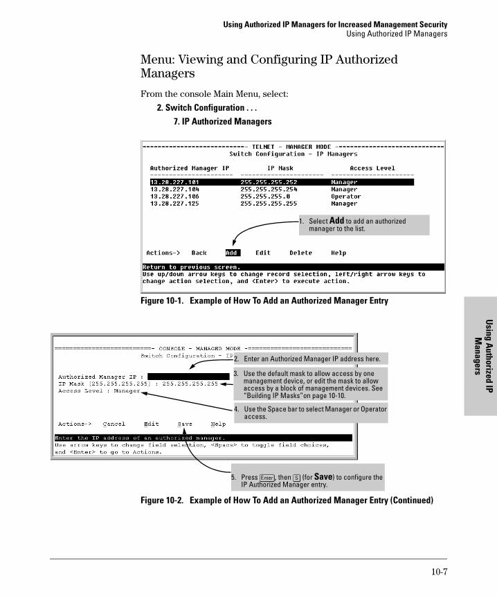
Using Authorized IP Managers for Increased Management SecurityUsing Authorized IP Managers
Using A
uthorized IP M
anagers
Menu: Viewing and Configuring IP Authorized Managers
From the console Main Menu, select:
2. Switch Configuration . . .7. IP Authorized Managers
Figure 10-1. Example of How To Add an Authorized Manager Entry
Figure 10-2. Example of How To Add an Authorized Manager Entry (Continued)
1. Select Add to add an authorized manager to the list.
5. Press [Enter], then [S] (for Save) to configure the IP Authorized Manager entry.
4. Use the Space bar to select Manager or Operator access.
3. Use the default mask to allow access by one management device, or edit the mask to allow access by a block of management devices. See “Building IP Masks”on page 10-10.
2. Enter an Authorized Manager IP address here.
10-7
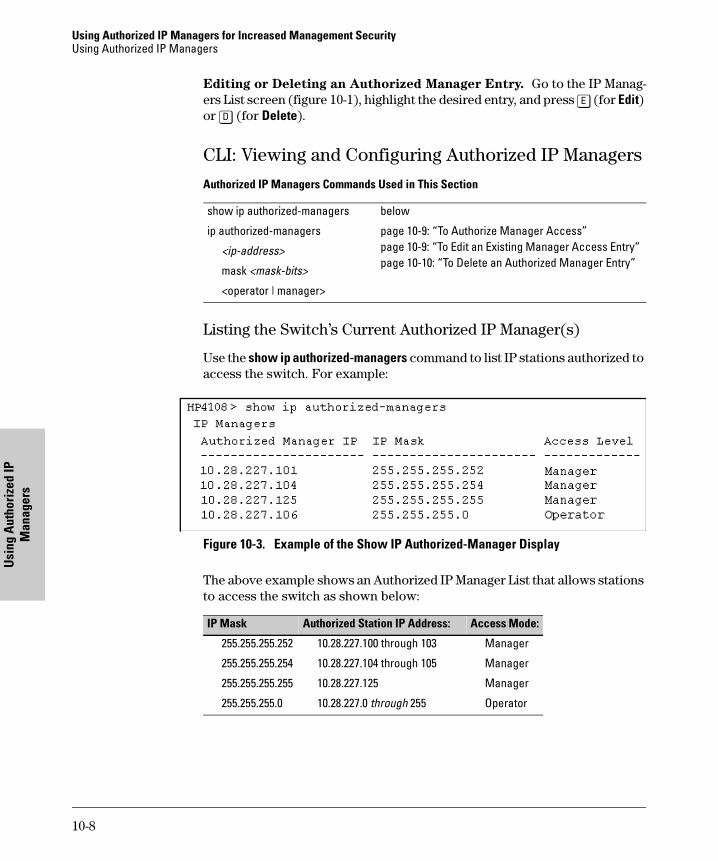
Using Authorized IP Managers for Increased Management SecurityUsing Authorized IP Managers
Usi
ng A
utho
rize
d IP
M
anag
ers
Editing or Deleting an Authorized Manager Entry. Go to the IP Manag-ers List screen (figure 10-1), highlight the desired entry, and press [E] (for Edit) or [D] (for Delete).
CLI: Viewing and Configuring Authorized IP Managers
Authorized IP Managers Commands Used in This Section
Listing the Switch’s Current Authorized IP Manager(s)
Use the show ip authorized-managers command to list IP stations authorized to access the switch. For example:
Figure 10-3. Example of the Show IP Authorized-Manager Display
The above example shows an Authorized IP Manager List that allows stations to access the switch as shown below:
show ip authorized-managers below
ip authorized-managers page 10-9: “To Authorize Manager Access” page 10-9: “To Edit an Existing Manager Access Entry” page 10-10: “To Delete an Authorized Manager Entry”
<ip-address>
mask <mask-bits>
<operator | manager>
IP Mask Authorized Station IP Address: Access Mode:
255.255.255.252 10.28.227.100 through 103 Manager
255.255.255.254 10.28.227.104 through 105 Manager
255.255.255.255 10.28.227.125 Manager
255.255.255.0 10.28.227.0 through 255 Operator
10-8
Using Authorized IP Managers for Increased Management SecurityUsing Authorized IP Managers
Using A
uthorized IP M
anagers
Configuring IP Authorized Managers for the Switch
Syntax: ip authorized-managers <ip address>[mask <mask-bits>]<operator | manager>
To Authorize Manager Access. This command authorizes manager-level access for any station having an IP address of 10.28.227.0 through 10.28.227.255:
HP4108(config)# ip authorized-managers
10.28.227.101 mask 255.255.255.0 manager
Similarly, the next command authorizes manager-level access for any station having an IP address of 10.28.227.101 through 103:
HP4108(config)# ip authorized-managers
10.28.227.101 mask 255.255.255.252 manager
If you omit the mask when adding a new authorized manager, the switch automatically uses 255.255.255.255 for the mask. If you do not specify either Manager or Operator access, the switch automatically assigns the Manager access. For example:
HP4108(config)# ip authorized-managers 10.28.227.105
The result of entering the above example is:
• Authorized Station IP Address: 10.28.227.105
• IP Mask: 255.255.255.255, which authorizes only the specified station (10.28.227.105 in this case). (See “Configuring Multiple Stations Per Authorized Manager IP Entry” on page 10-11.)
• Access Level: Manager
To Edit an Existing Manager Access Entry. To change the mask or access level for an existing entry, use the entry’s IP address and enter the new value(s). (Notice that any parameters not included in the command will be set to their default.):
HP4108(config)# ip authorized-managers
10.28.227.101 mask 255.255.255.0 operator
The above command replaces the existing mask and access level for IP address 10.28.227.101 with 255.255.255.0 and operator.
10-9
Using Authorized IP Managers for Increased Management SecurityUsing Authorized IP Managers
Usi
ng A
utho
rize
d IP
M
anag
ers
The following command replaces the existing mask and access level for IP address 10.28.227.101 with 255.0.0.0 and manager (the defaults) because the command does not specify either of these parameters .
HP4108(config)# ip authorized-managers 10.28.227.101
To Delete an Authorized Manager Entry. This command uses the IP address of the authorized manager you want to delete:
HP4108(config)# no ip authorized-managers 10.28.227.101
Web: Configuring IP Authorized Managers
In the web browser interface you can configure IP Authorized Managers as described below.
To Add, Modify, or Delete an IP Authorized Manager address:
1. Click on the Security tab.
2. Click on [Authorized Addresses].
3. Enter the appropriate parameter settings for the operation you want.
4. Click on [Add], [Replace], or [Delete] to implement the configuration change.
For web-based help on how to use the web browser interface screen, click on the [?] button provided on the web browser screen.
Building IP Masks
The IP Mask parameter controls how the switch uses an Authorized Manager IP value to recognize the IP addresses of authorized manager stations on your network.
Configuring One Station Per Authorized Manager IP Entry
This is the easiest way to apply a mask. If you have ten or fewer management and/or operator stations, you can configure them quickly by simply adding the address of each to the Authorized Manager IP list with 255.255.255.255 for the corresponding mask. For example, as shown in figure 10-3 on page 10-8, if you configure an IP address of 10.28.227.125 with an IP mask of 255.255.255.255, only a station having an IP address of 10.28.227.125 has management access to the switch.
10-10
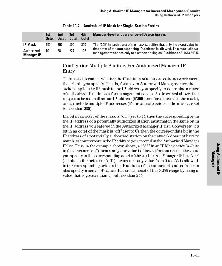
Using Authorized IP Managers for Increased Management SecurityUsing Authorized IP Managers
Using A
uthorized IP M
anagers
Table 10-2. Analysis of IP Mask for Single-Station Entries
Configuring Multiple Stations Per Authorized Manager IP Entry
The mask determines whether the IP address of a station on the network meets the criteria you specify. That is, for a given Authorized Manager entry, the switch applies the IP mask to the IP address you specify to determine a range of authorized IP addresses for management access. As described above, that range can be as small as one IP address (if 255 is set for all octets in the mask), or can include multiple IP addresses (if one or more octets in the mask are set to less than 255).
If a bit in an octet of the mask is “on” (set to 1), then the corresponding bit in the IP address of a potentially authorized station must match the same bit in the IP address you entered in the Authorized Manager IP list. Conversely, if a bit in an octet of the mask is “off” (set to 0), then the corresponding bit in the IP address of a potentially authorized station on the network does not have to match its counterpart in the IP address you entered in the Authorized Manager IP list. Thus, in the example shown above, a “255” in an IP Mask octet (all bits in the octet are “on”) means only one value is allowed for that octet—the value you specify in the corresponding octet of the Authorized Manager IP list. A “0” (all bits in the octet are “off”) means that any value from 0 to 255 is allowed in the corresponding octet in the IP address of an authorized station. You can also specify a series of values that are a subset of the 0-255 range by using a value that is greater than 0, but less than 255.
1st Octet
2nd Octet
3rd Octet
4th Octet
Manager-Level or Operator-Level Device Access
IP Mask 255 255 255 255 The “255” in each octet of the mask specifies that only the exact value in that octet of the corresponding IP address is allowed. This mask allows management access only to a station having an IP address of 10.33.248.5.Authorized
Manager IP10 28 227 125
10-11
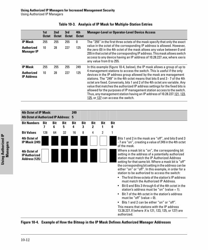
Using Authorized IP Managers for Increased Management SecurityUsing Authorized IP Managers
Usi
ng A
utho
rize
d IP
M
anag
ers
Table 10-3. Analysis of IP Mask for Multiple-Station Entries
Figure 10-4. Example of How the Bitmap in the IP Mask Defines Authorized Manager Addresses
1st Octet
2nd Octet
3rd Octet
4th Octet
Manager-Level or Operator-Level Device Access
IP Mask 255 255 255 0 The “255” in the first three octets of the mask specify that only the exact value in the octet of the corresponding IP address is allowed. However, the zero (0) in the 4th octet of the mask allows any value between 0 and 255 in that octet of the corresponding IP address. This mask allows switch access to any device having an IP address of 10.28.227.xxx, where xxx is any value from 0 to 255.
Authorized Manager IP
10 28 227 125
IP Mask 255 255 255 249 In this example (figure 10-4, below), the IP mask allows a group of up to 4 management stations to access the switch. This is useful if the only devices in the IP address group allowed by the mask are management stations. The “249” in the 4th octet means that bits 0 and 3 - 7 of the 4th octet are fixed. Conversely, bits 1 and 2 of the 4th octet are variable. Any value that matches the authorized IP address settings for the fixed bits is allowed for the purposes of IP management station access to the switch. Thus, any management station having an IP address of 10.28.227.121, 123, 125, or 127 can access the switch.
Authorized IP Address
10 28 227 125
4th Octet of IP Mask:4th Octet of Authorized IP Address:
2495
Bit Numbers Bit 7
Bit 6
Bit 5
Bit 4
Bit 3
Bit 2
Bit 1
Bit 0
Bit Values 128 64 32 16 8 4 2 1
4th Octet of IP Mask (249)
Bits 1 and 2 in the mask are “off”, and bits 0 and 3 - 7 are “on”, creating a value of 249 in the 4th octet of the mask.Where a mask bit is “on”, the corresponding bit setting in the address of a potentially authorized station must match the IP Authorized Address setting for that same bit. Where a mask bit is “off” the corresponding bit setting in the address can be either “on” or “off”. In this example, in order for a station to be authorized to access the switch:• The first three octets of the station’s IP address
must match the Authorized IP Address.• Bit 0 and Bits 3 through 6 of the 4th octet in the
station’s address must be “on” (value = 1).• Bit 7 of the 4th octet in the station’s address
must be “off” (value = 0).• Bits 1 and 2 can be either “on” or “off”.This means that stations with the IP address 13.28.227.X (where X is 121, 123, 125, or 127) are authorized.
4th Octet of IP Authorized Address (125)
10-12
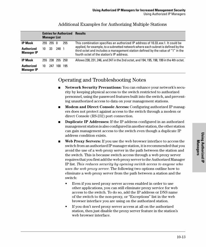
Using Authorized IP Managers for Increased Management SecurityUsing Authorized IP Managers
Using A
uthorized IP M
anagers
Additional Examples for Authorizing Multiple Stations
Operating and Troubleshooting Notes� Network Security Precautions: You can enhance your network’s secu-
rity by keeping physical access to the switch restricted to authorized personnel, using the password features built into the switch, and prevent-ing unauthorized access to data on your management stations.
� Modem and Direct Console Access: Configuring authorized IP manag-ers does not protect against access to the switch through a modem or direct Console (RS-232) port connection.
� Duplicate IP Addresses: If the IP address configured in an authorized management station is also configured in another station, the other station can gain management access to the switch even though a duplicate IP address condition exists.
� Web Proxy Servers: If you use the web browser interface to access the switch from an authorized IP manager station, it is recommended that you avoid the use of a web proxy server in the path between the station and the switch. This is because switch access through a web proxy server requires that you first add the web proxy server to the Authorized Manager IP list. This reduces security by opening switch access to anyone who
uses the web proxy server. The following two options outline how to eliminate a web proxy server from the path between a station and the switch:
• Even if you need proxy server access enabled in order to use other applications, you can still eliminate proxy service for web access to the switch. To do so, add the IP address or DNS name of the switch to the non-proxy, or “Exceptions” list in the web browser interface you are using on the authorized station.
• If you don’t need proxy server access at all on the authorized station, then just disable the proxy server feature in the station’s web browser interface.
Entries for Authorized Manager List
Results
IP Mask 255 255 0 255 This combination specifies an authorized IP address of 10.33.xxx.1. It could be applied, for example, to a subnetted network where each subnet is defined by the third octet and includes a management station defined by the value of “1” in the fourth octet of the station’s IP address.
Authorized Manager IP
10 33 248 1
IP Mask 255 238 255 250 Allows 230, 231, 246, and 247 in the 2nd octet, and 194, 195, 198, 199 in the 4th octet.
Authorized Manager IP
10 247 100 195
10-13

Using Authorized IP Managers for Increased Management SecurityUsing Authorized IP Managers
Usi
ng A
utho
rize
d IP
M
anag
ers
10-14
Ports: Traffic Control and Trunking
11
Optimizing Port Usage Through Traffic Control and Port Trunking
Chapter Contents
Overview . . . . . . . . . . . . . . . . . . . . . . . . . . . . . . . . . . . . . . . . . . . . . . . . . . . . . 11-2
Viewing Port Status and Configuring Port Parameters . . . . . . . . . . . . . . . 11-2
Menu: Viewing Port Status and Configuring Port Parameters . . . . . 11-5
CLI: Viewing Port Status and Configuring Port Parameters . . . . . . . 11-6
Web: Viewing Port Status and Configuring Port Parameters . . . . . . 11-9
Port Trunking . . . . . . . . . . . . . . . . . . . . . . . . . . . . . . . . . . . . . . . . . . . . . . . . 11-10
Switch 4108GL Port Trunk Features and Operation . . . . . . . . . . . . . 11-11
Trunk Configuration Methods . . . . . . . . . . . . . . . . . . . . . . . . . . . . . . . 11-12
Menu: Viewing and Configuring a Static Trunk Group . . . . . . . . . . . 11-16
CLI: Viewing and Configuring a Static or Dynamic Port Trunk Group . . . . . . . . . . . . . . . . . . . . . . . . . . . . . . . . . . . . . . . . . . . . . 11-18
Using the CLI To View Port Trunks . . . . . . . . . . . . . . . . . . . . . . . 11-18Using the CLI To Configure a Static or Dynamic Trunk Group 11-21
Web: Viewing Existing Port Trunk Groups . . . . . . . . . . . . . . . . . . . . 11-24
Trunk Group Operation Using LACP . . . . . . . . . . . . . . . . . . . . . . . . . 11-25Default Port Operation . . . . . . . . . . . . . . . . . . . . . . . . . . . . . . . . . 11-27LACP Notes and Restrictions . . . . . . . . . . . . . . . . . . . . . . . . . . . . 11-28
Trunk Group Operation Using the “Trunk” Option . . . . . . . . . . . . . . 11-28
Trunk Operation Using the “FEC” Option . . . . . . . . . . . . . . . . . . . . . 11-29
How the Switch Lists Trunk Data . . . . . . . . . . . . . . . . . . . . . . . . . . . . 11-29
Outbound Traffic Distribution Across Trunked Links . . . . . . . . . . . 11-30
11-1
Optimizing Port Usage Through Traffic Control and Port Trunking Overview
Port
s: T
raffi
c Co
ntro
lan
d Tr
unki
ng
Overview
This chapter includes:
� Configuring ports, including mode (speed and duplex), flow control, and broadcast control parameters (page 11-2)
� Creating and modifying a dynamic LACP or static port trunk group (page 11-10)
Port numbers in the status and configuration screens correspond to the port numbers on the front of the switch.
Viewing Port Status and Configuring Port ParametersPort Status and ConfigurationFeatures
N o t e O n C o n n e c t i n g Tr a n s c e i v e r s t o F i x e d -C o n f i g u r a t i o n D e v i c e s
If the switch either fails to show a link between an installed transceiver and another device, or demonstrates errors or other unexpected behavior on the link, check the port configuration on both devices for a speed and/or duplex mismatch. To check the speed and duplex setting on the Switch 4108GL, use either the Port Status screen in the menu interface (page 11-5) or show interfaces brief in the CLI (page 11-6).
Feature Default Menu CLI Web
viewing port status n/a page 11-5 page 11-6 page 11-9
configuring ports See Table 11-1 on pages 11-3 and 11-4..
page 11-5 page 11-8 page 11-9
11-2
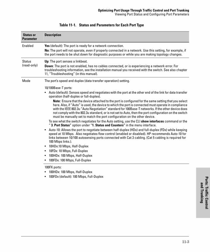
Optimizing Port Usage Through Traffic Control and Port TrunkingViewing Port Status and Configuring Port Parameters
Ports: Traffic Controland Trunking
Table 11-1. Status and Parameters for Each Port Type
Status or Parameter
Description
Enabled Yes (default): The port is ready for a network connection.No: The port will not operate, even if properly connected in a network. Use this setting, for example, if the port needs to be shut down for diagnostic purposes or while you are making topology changes.
Status(read-only)
Up: The port senses a linkbeat.Down: The port is not enabled, has no cables connected, or is experiencing a network error. For troubleshooting information, see the installation manual you received with the switch. See also chapter 11, “Troubleshooting” (in this manual).
Mode The port’s speed and duplex (data transfer operation) setting.
10/100Base-T ports:• Auto (default): Senses speed and negotiates with the port at the other end of the link for data transfer
operation (half-duplex or full-duplex).Note: Ensure that the device attached to the port is configured for the same setting that you select here. Also, if “Auto” is used, the device to which the port is connected must operate in compliance with the IEEE 802.3u “Auto Negotiation” standard for 100Base-T networks. If the other device does not comply with the 802.3u standard, or is not set to Auto, then the port configuration on the switch must be manually set to match the port configuration on the other device.
To see what the switch negotiates for the Auto setting, use the CLI show interfaces command or the “ 3. Port Status” option under “1. Status and Counters” in the menu interface.
• Auto-10: Allows the port to negotiate between half-duplex (HDx) and full-duplex (FDx) while keeping speed at 10 Mbps. Also negotiates flow control (enabled or disabled). HP recommends Auto-10 for links between 10/100 autosensing ports connected with Cat 3 cabling. (Cat 5 cabling is required for 100 Mbps links.).
• 10HDx:10 Mbps, Half-Duplex• 10FDx: 10 Mbps, Full-Duplex• 100HDx: 100 Mbps, Half-Duplex• 100FDx: 100 Mbps, Full-Duplex
100FX ports:• 100HDx: 100 Mbps, Half-Duplex• 100FDx (default): 100 Mbps, Full-Duplex
11-3
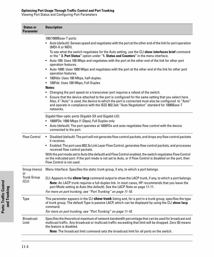
Optimizing Port Usage Through Traffic Control and Port Trunking Viewing Port Status and Configuring Port Parameters
Port
s: T
raffi
c Co
ntro
lan
d Tr
unki
ng
100/1000Base-T ports:• Auto (default): Senses speed and negotiates with the port at the other end of the link for port operation
(MDI-X or MDI). To see what the switch negotiates for the Auto setting, use the CLI show interfaces brief command or the “ 3. Port Status” option under “1. Status and Counters” in the menu interface.
• Auto-100: Uses 100 Mbps and negotiates with the port at the other end of the link for other port operation features.
• Auto-1000: Uses 1000 Mbps and negotiates with the port at the other end of the link for other port operation features.
• 100Hdx: Uses 100 Mbps, half-duplex.• 100Fdx: Uses 100 Mbps, Full-DuplexNotes: • Changing the port speed on a transceiver port requires a reboot of the switch.• Ensure that the device attached to the port is configured for the same setting that you select here.
Also, if “Auto” is used, the device to which the port is connected must also be configured to “Auto” and operate in compliance with the IEEE 802.3ab “Auto Negotiation” standard for 1000Base-T networks.
Gigabit fiber-optic ports (Gigabit-SX and Gigabit-LX):• 1000FDx: 1000 Mbps (1 Gbps), Full Duplex only• Auto (default): The port operates at 1000FDx and auto-negotiates flow control with the device
connected to the port.
Flow Control • Disabled (default): The port will not generate flow control packets, and drops any flow control packets it receives.
• Enabled: The port uses 802.3x Link Layer Flow Control, generates flow control packets, and processes received flow control packets.
With the port mode set to Auto (the default) and Flow Control enabled, the switch negotiates Flow Control on the indicated port. If the port mode is not set to Auto, or if Flow Control is disabled on the port, then Flow Control is not used.
Group (menu)orTrunk Group (CLI)
Menu Interface: Specifies the static trunk group, if any, to which a port belongs.
CLI: Appears in the show lacp command output to show the LACP trunk, if any, to which a port belongs.Note: An LACP trunk requires a full-duplex link. In most cases, HP recommends that you leave the port Mode setting at Auto (the default). See the LACP Note on page 11-11.
For more on port trunking, see “Port Trunking” on page 11-10.
Type This parameter appears in the CLI show trunk listing and, for a port in a trunk group, specifies the type of trunk group. The default Type is passive LACP, which can be displayed by using the CLI show lacp command.For more on port trunking, see “Port Trunking” on page 11-10.
Broadcast Limit
Specifies the theoretical maximum of network bandwidth percentage that can be used for broadcast and multicast traffic. Any broadcast or multicast traffic exceeding that limit will be dropped. Zero (0) means the feature is disabled.
Note: The broadcast limit command sets the broadcast limit for all ports on the switch.
Status or Parameter
Description
11-4
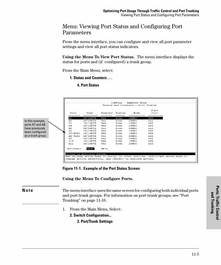
Optimizing Port Usage Through Traffic Control and Port TrunkingViewing Port Status and Configuring Port Parameters
Ports: Traffic Controland Trunking
Menu: Viewing Port Status and Configuring Port Parameters
From the menu interface, you can configure and view all port parameter settings and view all port status indicators.
Using the Menu To View Port Status. The menu interface displays the status for ports and (if configured) a trunk group.
From the Main Menu, select:
1. Status and Counters . . .
4. Port Status
Figure 11-1. Example of the Port Status Screen
Using the Menu To Configure Ports.
N o t e The menu interface uses the same screen for configuring both individual ports and port trunk groups. For information on port trunk groups, see “Port Trunking” on page 11-10.
1. From the Main Menu, Select:
2. Switch Configuration...2. Port/Trunk Settings
In this example, ports A7 and A8 have previously been configured as a trunk group.
11-5
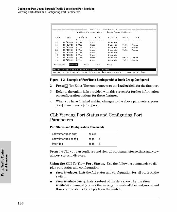
Optimizing Port Usage Through Traffic Control and Port Trunking Viewing Port Status and Configuring Port Parameters
Port
s: T
raffi
c Co
ntro
lan
d Tr
unki
ng
Figure 11-2. Example of Port/Trunk Settings with a Trunk Group Configured
2. Press [E] (for Edit). The cursor moves to the Enabled field for the first port.
3. Refer to the online help provided with this screen for further information on configuration options for these features.
4. When you have finished making changes to the above parameters, press [Enter], then press [S] (for Save).
CLI: Viewing Port Status and Configuring Port Parameters
Port Status and Configuration Commands
From the CLI, you can configure and view all port parameter settings and view all port status indicators.
Using the CLI To View Port Status. Use the following commands to dis-play port status and configuration:
� show interfaces: Lists the full status and configuration for all ports on the switch.
� show interface config: Lists a subset of the data shown by the show interfaces command (above); that is, only the enabled/disabled, mode, and flow control status for all ports on the switch.
show interfaces brief below
show interface config page 11-7
interface page 11-8
11-6

Optimizing Port Usage Through Traffic Control and Port TrunkingViewing Port Status and Configuring Port Parameters
Ports: Traffic Controland Trunking
Syntax: show interfaces briefshow interface config
The next two figures list examples of the output of the above two commands for the same port configuration.
Figure 11-3. Example of a Show Interface Command Listing
Figure 11-4. Example of a Show Interface Config Command Listing
11-7
Optimizing Port Usage Through Traffic Control and Port Trunking Viewing Port Status and Configuring Port Parameters
Port
s: T
raffi
c Co
ntro
lan
d Tr
unki
ng
Using the CLI To Configure Ports. You can configure one or more of the following port parameters. For details on each option, see Table 11-1 on page 11-3.
Syntax: [no] interface <[ethernet] port-list> disable | enablespeed-duplex <auto-10 |10-full | 10-half | 100-full | 100-half |auto|1000-full |>flow-control
Note that in the above syntax you can subsitute an “int” for “interface” and an “e” for “ethernet”; that is int e <port-list>.
For example, to configure ports C1 through C3 and port C6 for 100Mbps full-duplex, you would enter these commands:
HP4108(config)# int e c1-c3,c6 speed-duplex 100-full
Similarly, to configure a single port with the settings in the above command, you could either enter the same command with only the one port identified, or go to the context level for that port and then enter the command. For example, to enter the context level for port C6 and then configure that port for 100FDx :
HP4108(config)# int e c6HP4108(eth-C6)# speed-duplex 100-full
If port C8 was disabled, and you wanted to enable it and configure it for 100FDx with flow-control active, you could do so with either of the following command sets.
� These commands enable and configure port C8 from the config level:HP4108(config)# int e c8 enable HP4108(config)# int e c8 speed-duplex 100-fullHP4108(config)# int e c8 flow-control
� These commands select the context level for port C8 and then apply all of the configuration commands to port C8:HP4108(config)# int e c8HP4108(eth-C8)# enable HP4108(eth-C8)# speed-duplex 100-full HP4108(eth-C8)# flow-control
11-8
Optimizing Port Usage Through Traffic Control and Port TrunkingViewing Port Status and Configuring Port Parameters
Ports: Traffic Controland Trunking
Configuring a Broadcast Limit on the Switch. Executing this command configures the broadcast limit for all ports on the switch.
Syntax: broadcast-limit <0 . . 99>
For example, to configure a broadcast limit of 20% for all ports on the switch:
HP4108(config)# broadcast-limit 20
Web: Viewing Port Status and Configuring Port Parameters
In the web browser interface:
1. Click on the Configuration tab.
2. Click on [Port Configuration].
3. Select the ports you want to modify and click on [Modify Selected Ports].
4. After you make the desired changes, click on [Apply Settings].
Note that the web browser interface displays an existing port trunk group. However, to configure a port trunk group, you must use the CLI or the menu interface. For more on this topic, see “Port Trunking” on page 11-10.
11-9
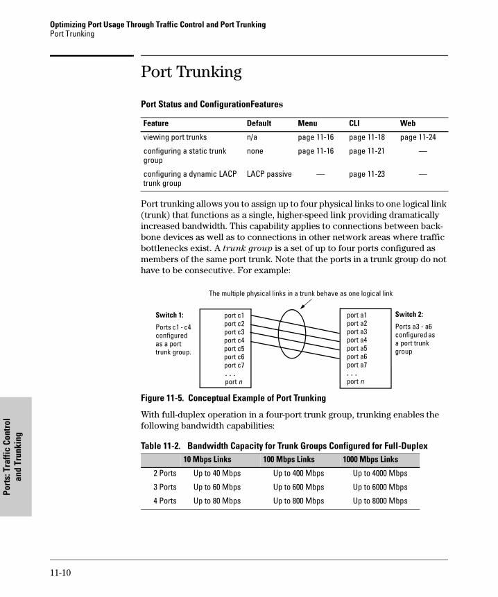
Optimizing Port Usage Through Traffic Control and Port Trunking Port Trunking
Port
s: T
raffi
c Co
ntro
lan
d Tr
unki
ng
Port Trunking
Port Status and ConfigurationFeatures
Port trunking allows you to assign up to four physical links to one logical link (trunk) that functions as a single, higher-speed link providing dramatically increased bandwidth. This capability applies to connections between back-bone devices as well as to connections in other network areas where traffic bottlenecks exist. A trunk group is a set of up to four ports configured as members of the same port trunk. Note that the ports in a trunk group do not have to be consecutive. For example:
Figure 11-5. Conceptual Example of Port Trunking
With full-duplex operation in a four-port trunk group, trunking enables the following bandwidth capabilities:
Table 11-2. Bandwidth Capacity for Trunk Groups Configured for Full-Duplex
Feature Default Menu CLI Web
viewing port trunks n/a page 11-16 page 11-18 page 11-24
configuring a static trunk group
none page 11-16 page 11-21 —
configuring a dynamic LACP trunk group
LACP passive — page 11-23 —
10 Mbps Links 100 Mbps Links 1000 Mbps Links
2 Ports Up to 40 Mbps Up to 400 Mbps Up to 4000 Mbps
3 Ports Up to 60 Mbps Up to 600 Mbps Up to 6000 Mbps
4 Ports Up to 80 Mbps Up to 800 Mbps Up to 8000 Mbps
Switch 1:
Ports c1 - c4 configured as a port trunk group.
The multiple physical links in a trunk behave as one logical link
port c1 port c2 port c3 port c4 port c5 port c6 port c7 . . . port n
port a1 port a2 port a3 port a4 port a5 port a6port a7. . .port n
Switch 2:
Ports a3 - a6 configured as a port trunk group
11-10
Optimizing Port Usage Through Traffic Control and Port TrunkingPort Trunking
Ports: Traffic Controland Trunking
Port Connections and Configuration: All port trunk links must be point-to-point connections between the Switch 4108GL and another switch, router, server, or workstation configured for port trunking. No intervening, non-trunking devices are allowed. It is important to note that ports on both ends of a port trunk group must have the same mode (speed and duplex) and flow control settings.
N o t e Link Connections. The switch does not support port trunking through an intermediate, non-trunking device such as a hub, or using more than one media type in a port trunk group. Similarly, all links in the same trunk group must have the same speed, duplex, and flow control.
Port Security Restriction. Port security does not operate on a trunk group. If you configure port security on one or more ports that are later added to a trunk group, the switch will reset the port security parameters for those ports to the factory-default configuration.
C a u t i o n To avoid broadcast storms or loops in your network while configuring a trunk, first disable or disconnect all ports you want to add to or remove from the trunk. After you finish configuring the trunk, enable or re-connect the ports.
Switch 4108GL Port Trunk Features and Operation
The Switch 4108GL offers these options for port trunking:
� LACP (IEEE 802.3ad—page 11-25)
� Trunk (non-protocol—page 11-28)
� FEC (Fast EtherChannel®—page 11-29)
The switch supports six trunk groups of up to four ports each. (Using the Link Aggregation Control Protocol—LACP—option, you can include standby trunked ports in addition to the maximum of four actively trunking ports.)
L A C P N o t e LACP operation requires full-duplex (FDx) links. For most installations, HP recommends that you leave the port Mode settings at Auto (the default). LACP also operates with Auto-10, Auto-100, and Auto-1000 (if negotiation selects FDx); 10FDx, 100FDx, and 1000FDx settings.
Fault Tolerance: If a link in a port trunk fails, the switch redistributes traffic originally destined for that link to the remaining links in the trunk. The trunk remains operable as long as there is at least one link in operation. If a
11-11
Optimizing Port Usage Through Traffic Control and Port Trunking Port Trunking
Port
s: T
raffi
c Co
ntro
lan
d Tr
unki
ng
link is restored, that link is automatically included in the traffic distribution again. The LACP option also offers a standby link capability, which enables you to keep links in reserve for service if one or more of the original active links fails. See “Trunk Group Operation Using LACP” on page 11-25.)
Trunk Configuration Methods
Dynamic LACP Trunk: The switch automatically negotiates trunked links between LACP-configured ports on separate devices, and offers one dynamic trunk option: LACP. To configure the switch to initiate a dynamic LACP trunk with another device, use the interface ethernet command in the CLI to set the default LACP option to Active on the ports you want to use for the trunk. For example, the following command sets ports C1-C4 to LACP active:
HP4108(config) int e c1-c4 lacp active
Note that the above example works if the ports are not already operating in a trunk. To change the LACP option on ports already operating as a trunk, you must first remove them from the trunk. For example, if ports C1 - C4 were LACP-active and operating in a trunk with another device, you would do the following to change them to LACP-passive:
HP4108(config)# no int e c1-c4 lacp Removes the ports fromthe trunk.
HP4108(config)# int e c1-c4 Configures LACPlacp passive passive.
Static Trunk: The switch uses the links you configure with the Port/Trunk Settings screen in the menu interface or the trunk command in the CLI to create a static port trunk. The switch offers three types of static trunks: LACP, Trunk, and FEC.
Table 11-3. Trunk Types Used in Static and Dynamic Trunk Groups
Trunking Method
LACP Trunk FEC
Dynamic Yes No No
Static Yes Yes Yes
11-12
Optimizing Port Usage Through Traffic Control and Port TrunkingPort Trunking
Ports: Traffic Controland Trunking
Table 11-4. Trunk Configuration Protocols
Protocol Trunking Options
LACP (802.3ad)
Provides dynamic and static LACP trunking options.• Dynamic LACP — Use the switch-negotiated dynamic LACP trunk when:
– The port on the other end of the trunk link is configured for Active or Passive LACP. – You want to achieve fault-tolerance for high-availability applications where you want a four-link trunk
with one or more standby links available in case an active link goes down. (Both ends of the link must be dynamic LACP.)
• Static LACP — Use the manually configured static LACP trunk when:– The port on the other end of the trunk link is configured for a static LACP trunk– You want to configure non-default spanning tree (STP) or IGMP parameters on an LACP trunk group.– You want an LACP trunk group to operate in a VLAN other than the default VLAN and GVRP is disabled.– You want to use a monitor port on the switch to monitor an LACP trunk.
See “Trunk Group Operation Using LACP” on page 11-25.
Trunk(non-protocol)
Provides manually configured, static-only trunking to:• Most HP switches and routing switches not running the 802.3ad LACP protocol.• Windows NT and HP-UX workstations and serversUse the Trunk option when:
– The device to which you want to create a trunk link is using a non-802.3ad trunking protocol– You are unsure which type of trunk to use, or the device to which you want to create a trunk link is
using an unknown trunking protocol.– You want to use a monitor port on the switch to monitor traffic on a trunk.
See “Trunk Group Operation Using the “Trunk” Option” on page 11-28.
FEC Provides static trunking to forwarding devices that also support FEC (Fast EtherChannel® ), such as some Cisco® switches and routers, and some HP-UX and Windows NT servers.
See “Trunk Operation Using the FEC Option” on page 11-29.
11-13
Optimizing Port Usage Through Traffic Control and Port Trunking Port Trunking
Port
s: T
raffi
c Co
ntro
lan
d Tr
unki
ng
Table 11-5. General Operating Rules for Port Trunks
Media: All ports on both ends of a trunk group must have the same media type and mode (speed and duplex). The switch blocks any trunked links that do not conform to this rule. (For the Switch 4108GL, HP recommends leaving the port Mode setting at Auto or, in networks using Cat 3 cabling, Auto-10.)Port Configuration: The default port configuration on the Switch 4108GL is Auto, which enables a port to sense speed and negotiate duplex with an Auto-enabled port on another device. HP recommends that you use the Auto setting for all ports you plan to use for trunking. Otherwise, you must manually ensure that the mode setting for each port in a trunk is compatible with the other ports in the trunk.
All of the following operate on a per-port basis, regardless of trunk membership:• Enable/Disable• Flow control (Flow Ctrl)LACP is a full-duplex protocol. See “Trunk Group Operation Using LACP” on page 11-25.
Trunk Configuration: All ports in the same trunk group must be the same trunk type (LACP, Trunk, or FEC). All LACP ports in the same trunk group must be either all static LACP or all dynamic LACP.A trunk appears as a single port labeled Dyn1 (for an LACP dynamic trunk) or Trk1 (for a static trunk of any type: LACP, Trunk, or FEC) on various menu and CLI screens. For a listing of which screens show which trunk types, see “How the Switch Lists Trunk Data” on page 11-29.
For STP or VLAN operation, configuration for all ports in a trunk is done at the trunk level. (You cannot separately configure individual ports within a trunk for STP or VLAN operation.)
Traffic Distribution: All of the switch trunk protocols use the SA/DA (Source Address/Destination Address) method of distributing traffic across the trunked links. See “Outbound Traffic Distribution Across Trunked Links” on page 11-30.
Recommended Port Mode Setting for LACP
11-14
Optimizing Port Usage Through Traffic Control and Port TrunkingPort Trunking
Ports: Traffic Controland Trunking
Spanning Tree Protocol (STP): STP operates as a global setting on the switch (one instance of STP per switch). However, you can adjust STP parameters on a per-port basis. A static trunk of any type appears in the STP configuration display, and you can configure STP parameters for a static trunk in the same way that you would configure STP parameters on a non-trunked port. (Note that the switch lists the trunk by name—such as Trk1—and does not list the individual ports in the trunk.) For example, if ports C1 and C2 are configured as a static trunk named Trk1, they are listed in the STP display as TRK1 and do not appear as individual ports in the STP displays.
When Spanning Tree forwards on a trunk, all ports in the trunk will be forwarding. Conversely, when Spanning Tree blocks a trunk, all ports in the trunk are blocked.
Note: A dynamic LACP trunk operates only with the default STP settings and does not appear in the STP configuration display or show ip igmp listing.
If you remove a port from a static trunk, the port retains the same STP settings that were configured for the trunk.
IP Multicast Protocol (IGMP): A static trunk of any type appears in the IGMP configuration display, and you can configure IGMP for a static trunk in the same way that you would configure IGMP on a non-trunked port. (Note that the switch lists the trunk by name—such as Trk1—and does not list the individual ports in the trunk.) Also, creating a new trunk automatically places the trunk in IGMP Auto status if IGMP is enabled for the default VLAN. A dynamic LACP trunk operates only with the default IGMP settings and does not appear in the IGMP configuration display or show ip igmp listing.
VLANs: Creating a new trunk automatically places the trunk in the DEFAULT_VLAN, regardless of whether the ports in the trunk were in another VLAN. Similarly, removing a port from a trunk group automatically places the port in the default VLAN. You can configure a static trunk in the same way that you configure a port for membership in any VLAN.
Note: For a dynamic trunk to operate in a VLAN other than the default VLAN (DEFAULT_VLAN), GVRP must be enabled. See “Trunk Group Operation Using LACP” on page 11-25.
Port Security: Trunk groups (and their individual ports) cannot be configured for port security, and the switch excludes trunked ports from the show port-security listing. If you configure non-default port security settings for a port, then subsequently place the port in a trunk, the port security for that port returns to the default settings. If you remove a port from a trunk, the port security settings for that port are returned to their default values.
Monitor Port: Note: A trunk cannot be a monitor port. A monitor port can monitor a static trunk but cannot monitor a dynamic LACP trunk.
In this example showing part of the show spanning-tree listing, ports C1 and C2 are members of TRK1 and do not appear as individual ports in the port configuration part of the listing.
11-15
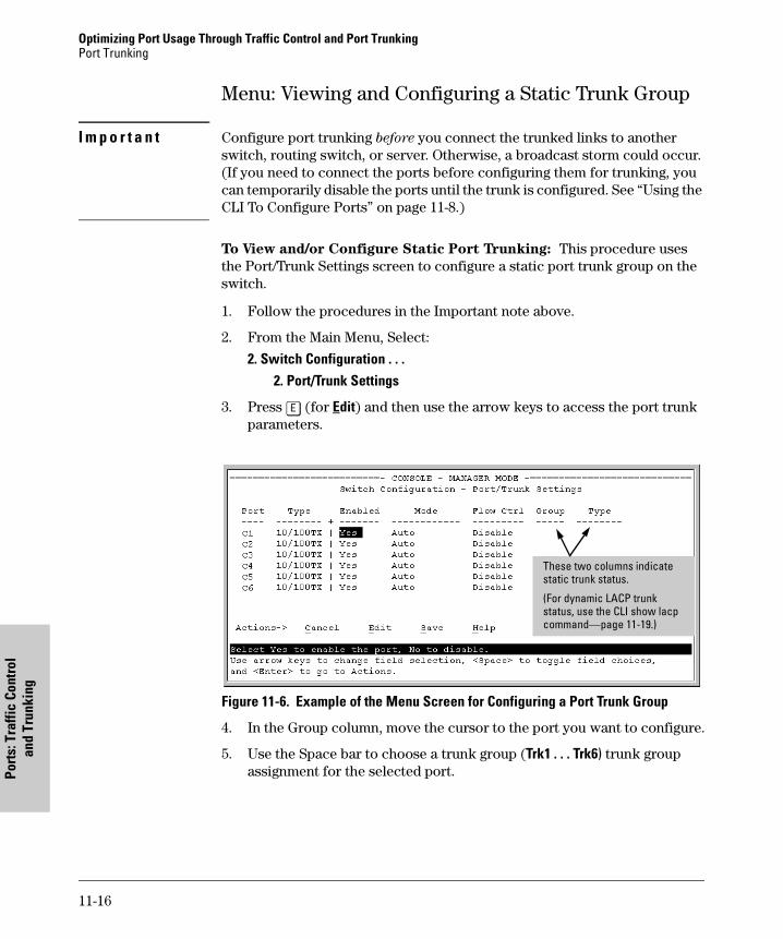
Optimizing Port Usage Through Traffic Control and Port Trunking Port Trunking
Port
s: T
raffi
c Co
ntro
lan
d Tr
unki
ng
Menu: Viewing and Configuring a Static Trunk Group
I m p o r t a n t Configure port trunking before you connect the trunked links to another switch, routing switch, or server. Otherwise, a broadcast storm could occur. (If you need to connect the ports before configuring them for trunking, you can temporarily disable the ports until the trunk is configured. See “Using the CLI To Configure Ports” on page 11-8.)
To View and/or Configure Static Port Trunking: This procedure uses the Port/Trunk Settings screen to configure a static port trunk group on the switch.
1. Follow the procedures in the Important note above.
2. From the Main Menu, Select:
2. Switch Configuration . . .2. Port/Trunk Settings
3. Press [E] (for Edit) and then use the arrow keys to access the port trunk parameters.
Figure 11-6. Example of the Menu Screen for Configuring a Port Trunk Group
4. In the Group column, move the cursor to the port you want to configure.
5. Use the Space bar to choose a trunk group (Trk1 . . . Trk6) trunk group assignment for the selected port.
These two columns indicate static trunk status.
(For dynamic LACP trunk status, use the CLI show lacp command—page 11-19.)
11-16
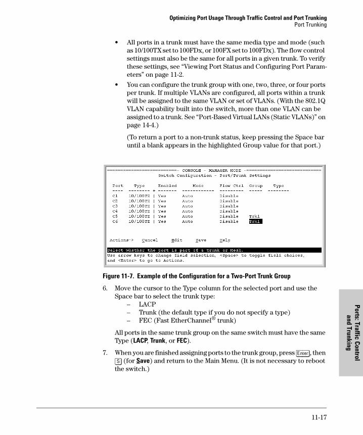
Optimizing Port Usage Through Traffic Control and Port TrunkingPort Trunking
Ports: Traffic Controland Trunking
• All ports in a trunk must have the same media type and mode (such as 10/100TX set to 100FDx, or 100FX set to 100FDx). The flow control settings must also be the same for all ports in a given trunk. To verify these settings, see “Viewing Port Status and Configuring Port Param-eters” on page 11-2.
• You can configure the trunk group with one, two, three, or four ports per trunk. If multiple VLANs are configured, all ports within a trunk will be assigned to the same VLAN or set of VLANs. (With the 802.1Q VLAN capability built into the switch, more than one VLAN can be assigned to a trunk. See “Port-Based Virtual LANs (Static VLANs)” on page 14-4.)
(To return a port to a non-trunk status, keep pressing the Space bar until a blank appears in the highlighted Group value for that port.)
Figure 11-7. Example of the Configuration for a Two-Port Trunk Group
6. Move the cursor to the Type column for the selected port and use the Space bar to select the trunk type:
– LACP– Trunk (the default type if you do not specify a type)– FEC (Fast EtherChannel® trunk)
All ports in the same trunk group on the same switch must have the same Type (LACP, Trunk, or FEC).
7. When you are finished assigning ports to the trunk group, press [Enter], then [S] (for Save) and return to the Main Menu. (It is not necessary to reboot the switch.)
11-17
Optimizing Port Usage Through Traffic Control and Port Trunking Port Trunking
Port
s: T
raffi
c Co
ntro
lan
d Tr
unki
ng
During the Save process, traffic on the ports configured for trunking will be delayed for several seconds. If the Spanning Tree Protocol is enabled, the delay may be up to 30 seconds.
8. Connect the trunked ports on the switch to the corresponding ports on the opposite device. If you previously disabled any of the trunked ports on the switch, enable them now. (See “Viewing Port Status and Configur-ing Port Parameters” on page 11-2.)
Check the Event Log (page “Using the Event Log To Identify Problem Sources” on page 18-16) to verify that the trunked ports are operating properly.
CLI: Viewing and Configuring a Static or Dynamic Port Trunk Group
Trunk Status and Configuration Commands
Using the CLI To View Port Trunks
You can list the trunk type and group for all ports on the switch or for selected ports. You can also list LACP-only status information for LACP-configured ports.
Listing Static Trunk Type and Group for All Ports or Selected Ports.
Syntax: show trunks [<port-list>]
Omitting the <port-list> parameter results in a static trunk data listing for all LAN ports in the switch.
show trunks below
show lacp page 11-19
trunk page 11-21
interface lacp page 11-23
11-18
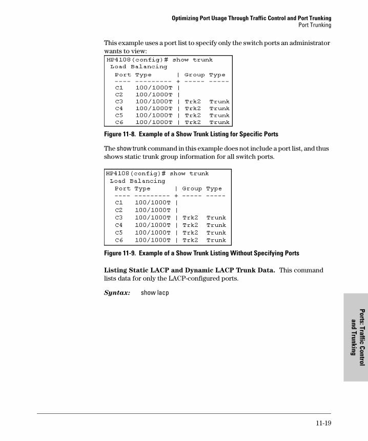
Optimizing Port Usage Through Traffic Control and Port TrunkingPort Trunking
Ports: Traffic Controland Trunking
This example uses a port list to specify only the switch ports an administrator wants to view:
Figure 11-8. Example of a Show Trunk Listing for Specific Ports
The show trunk command in this example does not include a port list, and thus shows static trunk group information for all switch ports.
Figure 11-9. Example of a Show Trunk Listing Without Specifying Ports
Listing Static LACP and Dynamic LACP Trunk Data. This command lists data for only the LACP-configured ports.
Syntax: show lacp
11-19
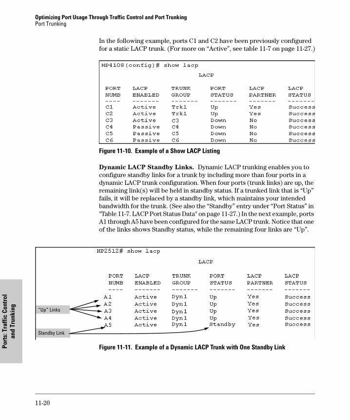
Optimizing Port Usage Through Traffic Control and Port Trunking Port Trunking
Port
s: T
raffi
c Co
ntro
lan
d Tr
unki
ng
In the following example, ports C1 and C2 have been previously configured for a static LACP trunk. (For more on “Active”, see table 11-7 on page 11-27.)
Figure 11-10. Example of a Show LACP Listing
Dynamic LACP Standby Links. Dynamic LACP trunking enables you to configure standby links for a trunk by including more than four ports in a dynamic LACP trunk configuration. When four ports (trunk links) are up, the remaining link(s) will be held in standby status. If a trunked link that is “Up” fails, it will be replaced by a standby link, which maintains your intended bandwidth for the trunk. (See also the “Standby” entry under “Port Status” in "Table 11-7. LACP Port Status Data" on page 11-27.) In the next example, ports A1 through A5 have been configured for the same LACP trunk. Notice that one of the links shows Standby status, while the remaining four links are “Up”.
Figure 11-11. Example of a Dynamic LACP Trunk with One Standby Link
“Up” Links
Standby Link
11-20
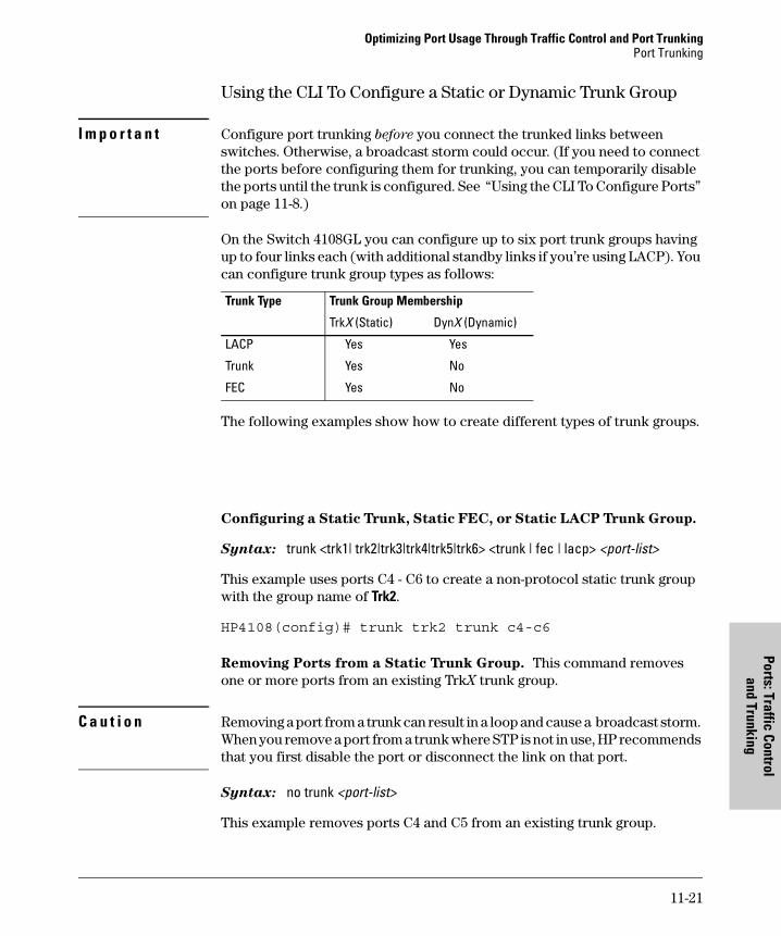
Optimizing Port Usage Through Traffic Control and Port TrunkingPort Trunking
Ports: Traffic Controland Trunking
Using the CLI To Configure a Static or Dynamic Trunk Group
I m p o r t a n t Configure port trunking before you connect the trunked links between switches. Otherwise, a broadcast storm could occur. (If you need to connect the ports before configuring them for trunking, you can temporarily disable the ports until the trunk is configured. See “Using the CLI To Configure Ports” on page 11-8.)
On the Switch 4108GL you can configure up to six port trunk groups having up to four links each (with additional standby links if you’re using LACP). You can configure trunk group types as follows:
The following examples show how to create different types of trunk groups.
Configuring a Static Trunk, Static FEC, or Static LACP Trunk Group.
Syntax: trunk <trk1| trk2|trk3|trk4|trk5|trk6> <trunk | fec | lacp> <port-list>
This example uses ports C4 - C6 to create a non-protocol static trunk group with the group name of Trk2.
HP4108(config)# trunk trk2 trunk c4-c6
Removing Ports from a Static Trunk Group. This command removes one or more ports from an existing TrkX trunk group.
C a u t i o n Removing a port from a trunk can result in a loop and cause a broadcast storm. When you remove a port from a trunk where STP is not in use, HP recommends that you first disable the port or disconnect the link on that port.
Syntax: no trunk <port-list>
This example removes ports C4 and C5 from an existing trunk group.
Trunk Type Trunk Group Membership
TrkX (Static) DynX (Dynamic)
LACP Yes Yes
Trunk Yes No
FEC Yes No
11-21

Optimizing Port Usage Through Traffic Control and Port Trunking Port Trunking
Port
s: T
raffi
c Co
ntro
lan
d Tr
unki
ng
HP4108(config)# no trunk c4-c5
11-22
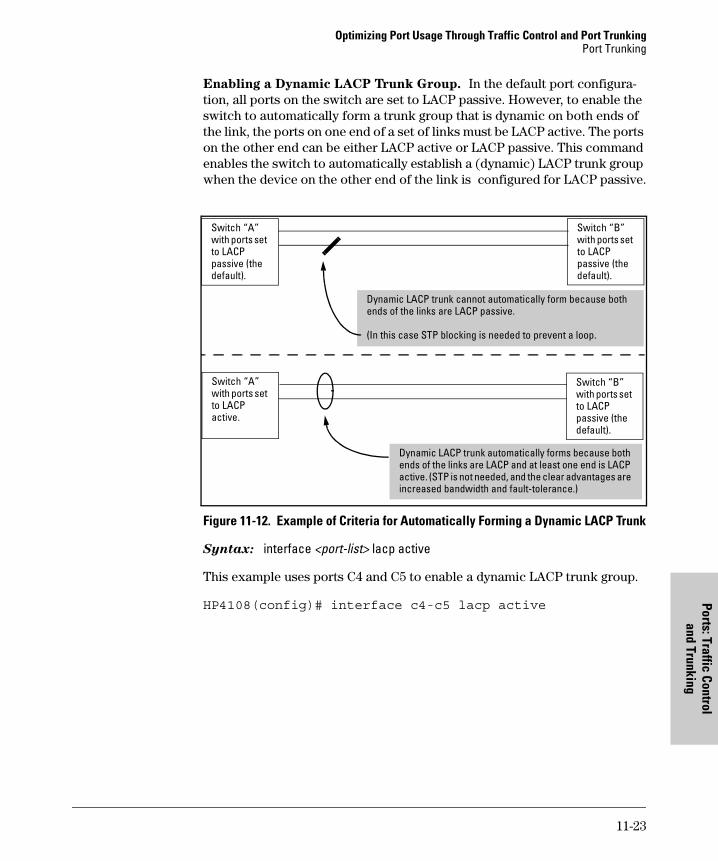
Optimizing Port Usage Through Traffic Control and Port TrunkingPort Trunking
Ports: Traffic Controland Trunking
Enabling a Dynamic LACP Trunk Group. In the default port configura-tion, all ports on the switch are set to LACP passive. However, to enable the switch to automatically form a trunk group that is dynamic on both ends of the link, the ports on one end of a set of links must be LACP active. The ports on the other end can be either LACP active or LACP passive. This command enables the switch to automatically establish a (dynamic) LACP trunk group when the device on the other end of the link is configured for LACP passive.
Figure 11-12. Example of Criteria for Automatically Forming a Dynamic LACP Trunk
Syntax: interface <port-list> lacp active
This example uses ports C4 and C5 to enable a dynamic LACP trunk group.
HP4108(config)# interface c4-c5 lacp active
Switch “A” with ports set to LACP passive (the default).
Switch “B” with ports set to LACP passive (the default).
Dynamic LACP trunk cannot automatically form because both ends of the links are LACP passive.
(In this case STP blocking is needed to prevent a loop.
Switch “A” with ports set to LACP active.
Switch “B” with ports set to LACP passive (the default).
Dynamic LACP trunk automatically forms because both ends of the links are LACP and at least one end is LACP active. (STP is not needed, and the clear advantages are increased bandwidth and fault-tolerance.)
11-23
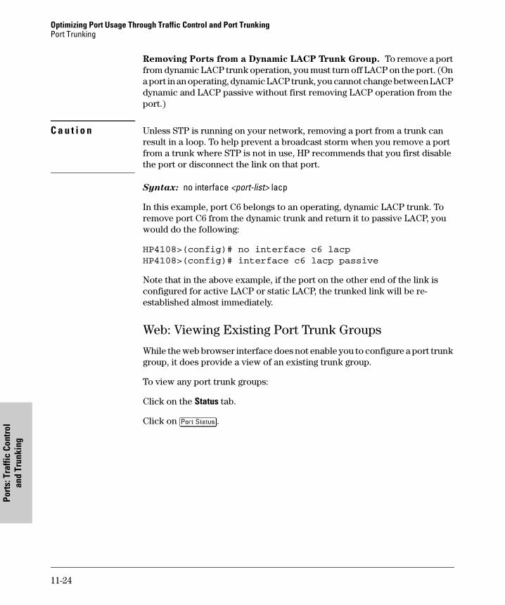
Optimizing Port Usage Through Traffic Control and Port Trunking Port Trunking
Port
s: T
raffi
c Co
ntro
lan
d Tr
unki
ng
Removing Ports from a Dynamic LACP Trunk Group. To remove a port from dynamic LACP trunk operation, you must turn off LACP on the port. (On a port in an operating, dynamic LACP trunk, you cannot change between LACP dynamic and LACP passive without first removing LACP operation from the port.)
C a u t i o n Unless STP is running on your network, removing a port from a trunk can result in a loop. To help prevent a broadcast storm when you remove a port from a trunk where STP is not in use, HP recommends that you first disable the port or disconnect the link on that port.
Syntax: no interface <port-list> lacp
In this example, port C6 belongs to an operating, dynamic LACP trunk. To remove port C6 from the dynamic trunk and return it to passive LACP, you would do the following:
HP4108>(config)# no interface c6 lacp
HP4108>(config)# interface c6 lacp passive
Note that in the above example, if the port on the other end of the link is configured for active LACP or static LACP, the trunked link will be re-established almost immediately.
Web: Viewing Existing Port Trunk Groups
While the web browser interface does not enable you to configure a port trunk group, it does provide a view of an existing trunk group.
To view any port trunk groups:
Click on the Status tab.
Click on [Port Status].
11-24
Optimizing Port Usage Through Traffic Control and Port TrunkingPort Trunking
Ports: Traffic Controland Trunking
Trunk Group Operation Using LACP
The switch can automatically configure a dynamic LACP trunk group or you can manually configure a static LACP trunk group. The methods for displaying
N o t e LACP requires full-duplex (FDx) links of the same media type (10/100Base-T, 100FX, etc.) and speed, and enforces speed and duplex conformance across a trunk group.
LACP trunk status include:
In most cases, trunks configured for LACP on the Switch 4108GL operate as described in table 11-6:
Trunk Display Method Static LACP Trunk Dynamic LACP Trunk
CLI show lacp command Included in listing. Included in listing.
CLI show trunk command Included in listing. Not included.
Port/Trunk Settings screen in menu interface Included in listing. Not included
11-25
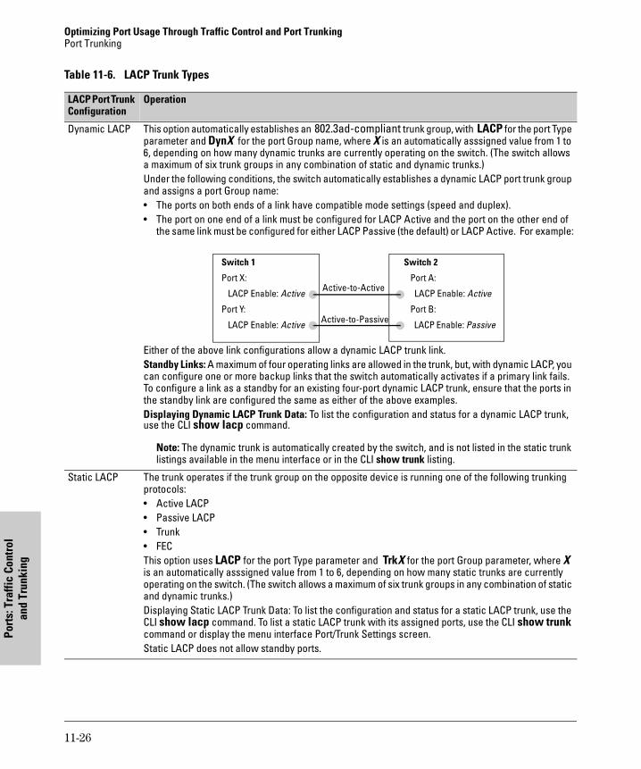
Optimizing Port Usage Through Traffic Control and Port Trunking Port Trunking
Port
s: T
raffi
c Co
ntro
lan
d Tr
unki
ng
Table 11-6. LACP Trunk Types
LACP Port Trunk Configuration
Operation
Dynamic LACP This option automatically establishes an 802.3ad-compliant trunk group, with LACP for the port Type parameter and DynX for the port Group name, where X is an automatically asssigned value from 1 to 6, depending on how many dynamic trunks are currently operating on the switch. (The switch allows a maximum of six trunk groups in any combination of static and dynamic trunks.)Under the following conditions, the switch automatically establishes a dynamic LACP port trunk group and assigns a port Group name: • The ports on both ends of a link have compatible mode settings (speed and duplex).• The port on one end of a link must be configured for LACP Active and the port on the other end of
the same link must be configured for either LACP Passive (the default) or LACP Active. For example:
Either of the above link configurations allow a dynamic LACP trunk link.Standby Links: A maximum of four operating links are allowed in the trunk, but, with dynamic LACP, you can configure one or more backup links that the switch automatically activates if a primary link fails. To configure a link as a standby for an existing four-port dynamic LACP trunk, ensure that the ports in the standby link are configured the same as either of the above examples.Displaying Dynamic LACP Trunk Data: To list the configuration and status for a dynamic LACP trunk, use the CLI show lacp command.
Note: The dynamic trunk is automatically created by the switch, and is not listed in the static trunk listings available in the menu interface or in the CLI show trunk listing.
Static LACP The trunk operates if the trunk group on the opposite device is running one of the following trunking protocols:• Active LACP• Passive LACP• Trunk • FECThis option uses LACP for the port Type parameter and TrkX for the port Group parameter, where X is an automatically asssigned value from 1 to 6, depending on how many static trunks are currently operating on the switch. (The switch allows a maximum of six trunk groups in any combination of static and dynamic trunks.)Displaying Static LACP Trunk Data: To list the configuration and status for a static LACP trunk, use the CLI show lacp command. To list a static LACP trunk with its assigned ports, use the CLI show trunk command or display the menu interface Port/Trunk Settings screen.Static LACP does not allow standby ports.
Switch 1
Port X:
LACP Enable: Active
Port Y:
LACP Enable: Active
Switch 2
Port A:
LACP Enable: Active
Port B:
LACP Enable: Passive
Active-to-Active
Active-to-Passive
11-26
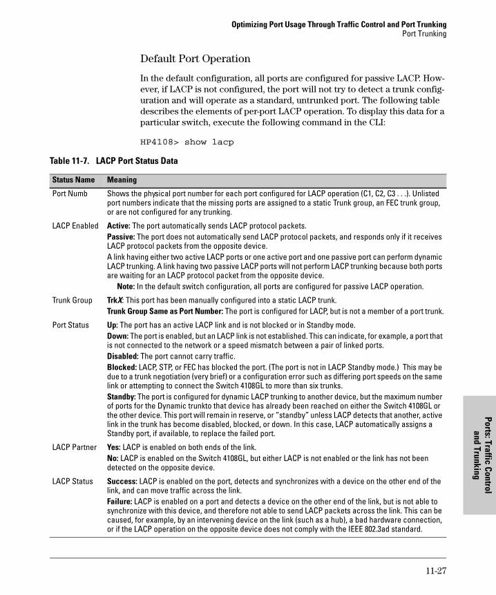
Optimizing Port Usage Through Traffic Control and Port TrunkingPort Trunking
Ports: Traffic Controland Trunking
Default Port Operation
In the default configuration, all ports are configured for passive LACP. How-ever, if LACP is not configured, the port will not try to detect a trunk config-uration and will operate as a standard, untrunked port. The following table describes the elements of per-port LACP operation. To display this data for a particular switch, execute the following command in the CLI:
HP4108> show lacp
Table 11-7. LACP Port Status Data
Status Name Meaning
Port Numb Shows the physical port number for each port configured for LACP operation (C1, C2, C3 . . .). Unlisted port numbers indicate that the missing ports are assigned to a static Trunk group, an FEC trunk group, or are not configured for any trunking.
LACP Enabled Active: The port automatically sends LACP protocol packets. Passive: The port does not automatically send LACP protocol packets, and responds only if it receives LACP protocol packets from the opposite device.A link having either two active LACP ports or one active port and one passive port can perform dynamic LACP trunking. A link having two passive LACP ports will not perform LACP trunking because both ports are waiting for an LACP protocol packet from the opposite device.
Note: In the default switch configuration, all ports are configured for passive LACP operation.
Trunk Group TrkX: This port has been manually configured into a static LACP trunk.Trunk Group Same as Port Number: The port is configured for LACP, but is not a member of a port trunk.
Port Status Up: The port has an active LACP link and is not blocked or in Standby mode.Down: The port is enabled, but an LACP link is not established. This can indicate, for example, a port that is not connected to the network or a speed mismatch between a pair of linked ports.Disabled: The port cannot carry traffic.Blocked: LACP, STP, or FEC has blocked the port. (The port is not in LACP Standby mode.) This may be due to a trunk negotiation (very brief) or a configuration error such as differing port speeds on the same link or attempting to connect the Switch 4108GL to more than six trunks. Standby: The port is configured for dynamic LACP trunking to another device, but the maximum number of ports for the Dynamic trunkto that device has already been reached on either the Switch 4108GL or the other device. This port will remain in reserve, or “standby” unless LACP detects that another, active link in the trunk has become disabled, blocked, or down. In this case, LACP automatically assigns a Standby port, if available, to replace the failed port.
LACP Partner Yes: LACP is enabled on both ends of the link.No: LACP is enabled on the Switch 4108GL, but either LACP is not enabled or the link has not been detected on the opposite device.
LACP Status Success: LACP is enabled on the port, detects and synchronizes with a device on the other end of the link, and can move traffic across the link.Failure: LACP is enabled on a port and detects a device on the other end of the link, but is not able to synchronize with this device, and therefore not able to send LACP packets across the link. This can be caused, for example, by an intervening device on the link (such as a hub), a bad hardware connection, or if the LACP operation on the opposite device does not comply with the IEEE 802.3ad standard.
11-27
Optimizing Port Usage Through Traffic Control and Port Trunking Port Trunking
Port
s: T
raffi
c Co
ntro
lan
d Tr
unki
ng
LACP Notes and Restrictions
Changing Trunking Methods. To convert a trunk from static to dynamic, you must first eliminate the static trunk.
Static LACP Trunks. Where a port is configured for LACP (Active or Passive), but does not belong to an existing trunk group, you can add that port to a static trunk. Doing so disables dynamic LACP on that port, which means you must manually configure both ends of the trunk.
VLANs and Dynamic LACP. A dynamic LACP trunk operates only in the default VLAN unless you have enabled GVRP on the switch. If you want to use LACP for a trunk on a non-default VLAN and GVRP is disabled, configure the trunk as a static trunk.
STP and IGMP. If spanning tree (STP) and/or IGMP is enabled in the switch, a dynamic LACP trunk operates only with the default settings for these features and does not appear in the port listings for these features.
Half-Duplex and/or Different Port Speeds Not Allowed in LACP
Trunks. The ports on both sides of an LACP trunk must be configured for the same speed and for full-duplex (FDx). The 802.3ad LACP standard speci-fies a full-duplex (FDx) requirement for LACP trunking.
A port configured as LACP passive and not assigned to a port trunk can be configured to half-duplex (HDx). However, in any of the following cases, a port cannot be reconfigured to an HDx setting:
� If a port is set to LACP Active, you cannot configure it to HDx.
� If a port is already a member of a static or dynamic LACP trunk, you cannot configure it to HDx.
� If a port is already set to HDx, the switch does not allow you to configure it for a static or dynamic LACP trunk.
Dynamic/Static LACP Interoperation: A port configured for dynamic LACP can properly interoperate with a port configured for static (TrkX) LACP, but any ports configured as standby LACP links will be ignored.
Trunk Group Operation Using the “Trunk” Option
This method creates a trunk group that operates independently of specific trunking protocols and does not use a protocol exchange with the device on the other end of the trunk. With this choice, the switch simply uses the SA/DA method of distributing outbound traffic across the trunked ports without
11-28
Optimizing Port Usage Through Traffic Control and Port TrunkingPort Trunking
Ports: Traffic Controland Trunking
regard for how that traffic is handled by the device at the other end of the trunked links. Similarly, the switch handles incoming traffic from the trunked links as if it were from a trunked source.
Use the Trunk option when you are trying to establish a trunk group between the Switch 4108GLh and another device, but the other device’s trunking operation fails to interoperate properly with LACP or FEC trunking configured on the Switch 4108GL.
Trunk Operation Using the “FEC” Option
This is the most flexible method for distributing traffic over trunked links when connecting to devices that use the FEC (Fast EtherChannel®) technol-ogy. FEC trunks offer the following benefits:
� Provide trunked connectivity to a FEC-compliant server, switch, or router.
� Enable quick convergence to remaining links when a failure is detected on a trunked port link.
� Depending on the capabilities of the device on the other end of the trunk, negotiate the forwarding mechanism on the trunk to the non-protocol option.
� When auto-negotiated to the SA/DA forwarding mechanism, provide higher performance on the trunk for broadcast, multicast, and flooded traffic through distribution in the same manner as non-protocol trunking.
� Support FEC automatic trunk configuration mode on other devices. That is, when connecting FEC trunks to FEC-capable servers, switches, or routers having FEC automatic trunk configuration mode enabled, the FEC trunks allow these other devices to automatically form trunk groups.
How the Switch Lists Trunk Data
Static Trunk Group: Appears in the menu interface and the output from the CLI show trunk and show interfaces commands.
Dynamic LACP Trunk Group: Appears in the output from the CLI show lacp command.
11-29
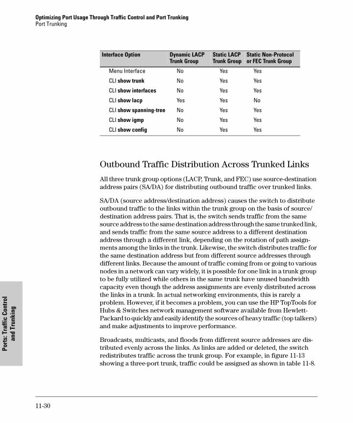
Optimizing Port Usage Through Traffic Control and Port Trunking Port Trunking
Port
s: T
raffi
c Co
ntro
lan
d Tr
unki
ng
Outbound Traffic Distribution Across Trunked Links
All three trunk group options (LACP, Trunk, and FEC) use source-destination address pairs (SA/DA) for distributing outbound traffic over trunked links.
SA/DA (source address/destination address) causes the switch to distribute outbound traffic to the links within the trunk group on the basis of source/destination address pairs. That is, the switch sends traffic from the same source address to the same destination address through the same trunked link, and sends traffic from the same source address to a different destination address through a different link, depending on the rotation of path assign-ments among the links in the trunk. Likewise, the switch distributes traffic for the same destination address but from different source addresses through different links. Because the amount of traffic coming from or going to various nodes in a network can vary widely, it is possible for one link in a trunk group to be fully utilized while others in the same trunk have unused bandwidth capacity even though the address assignments are evenly distributed across the links in a trunk. In actual networking environments, this is rarely a problem. However, if it becomes a problem, you can use the HP TopTools for Hubs & Switches network management software available from Hewlett-Packard to quickly and easily identify the sources of heavy traffic (top talkers) and make adjustments to improve performance.
Broadcasts, multicasts, and floods from different source addresses are dis-tributed evenly across the links. As links are added or deleted, the switch redistributes traffic across the trunk group. For example, in figure 11-13 showing a three-port trunk, traffic could be assigned as shown in table 11-8.
Interface Option Dynamic LACP Trunk Group
Static LACP Trunk Group
Static Non-Protocol or FEC Trunk Group
Menu Interface No Yes Yes
CLI show trunk No Yes Yes
CLI show interfaces No Yes Yes
CLI show lacp Yes Yes No
CLI show spanning-tree No Yes Yes
CLI show igmp No Yes Yes
CLI show config No Yes Yes
11-30
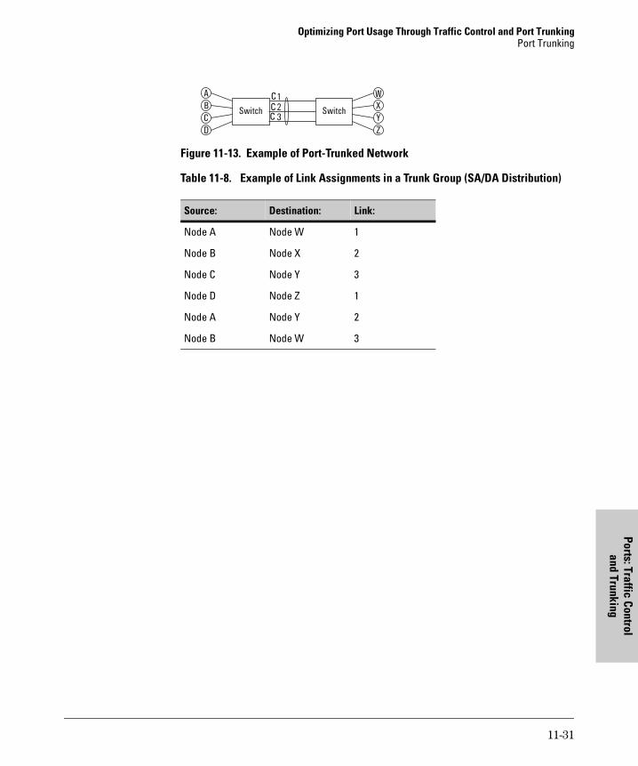
Optimizing Port Usage Through Traffic Control and Port TrunkingPort Trunking
Ports: Traffic Controland Trunking
Figure 11-13. Example of Port-Trunked Network
Table 11-8. Example of Link Assignments in a Trunk Group (SA/DA Distribution)
Source: Destination: Link:
Node A Node W 1
Node B Node X 2
Node C Node Y 3
Node D Node Z 1
Node A Node Y 2
Node B Node W 3
Switch Switch
A W
C Y
B X
D Z
123
CCC
11-31

Optimizing Port Usage Through Traffic Control and Port Trunking Port Trunking
Port
s: T
raffi
c Co
ntro
lan
d Tr
unki
ng
11-32
Monitoring and M
anthe Sw
itch
12
Configuring for Network Management Applications
Chapter Contents
Overview . . . . . . . . . . . . . . . . . . . . . . . . . . . . . . . . . . . . . . . . . . . . . . . . . . . . . 12-2
SNMP Management Features . . . . . . . . . . . . . . . . . . . . . . . . . . . . . . . . . 12-2
Configuring for SNMP Access to the Switch . . . . . . . . . . . . . . . . . . . . 12-4
SNMP Communities . . . . . . . . . . . . . . . . . . . . . . . . . . . . . . . . . . . . . . . . 12-5Menu: Viewing and Configuring SNMP Communities . . . . . . . . . 12-5CLI: Viewing and Configuring Community Names . . . . . . . . . . . 12-6
Trap Receivers and Authentication Traps . . . . . . . . . . . . . . . . . . . . . 12-8CLI: Configuring and Displaying Trap Receivers . . . . . . . . . . . . . 12-9Using the CLI To Enable Authentication Traps . . . . . . . . . . . . . 12-11
Advanced Management: RMON . . . . . . . . . . . . . . . . . . . . . . . . . . . . . . 12-11
CDP . . . . . . . . . . . . . . . . . . . . . . . . . . . . . . . . . . . . . . . . . . . . . . . . . . . . . . . . 12-12
Introduction . . . . . . . . . . . . . . . . . . . . . . . . . . . . . . . . . . . . . . . . . . . . . . 12-12
Outgoing Packets . . . . . . . . . . . . . . . . . . . . . . . . . . . . . . . . . . . . . . . . . 12-14
Incoming CDP Packets . . . . . . . . . . . . . . . . . . . . . . . . . . . . . . . . . . . . . 12-15
Configuring CDP on the Switch . . . . . . . . . . . . . . . . . . . . . . . . . . . . . . 12-18CLI: Viewing and Configuring CDP . . . . . . . . . . . . . . . . . . . . . . . 12-18
Viewing the Switch’s Current CDP Configuration . . . . . . . . . . . . . . 12-19
Viewing the Current Contents of the Switch’s CDP Neighbors Table . . . . . . . . . . . . . . . . . . . . . . . . . . . . . . . . . . . . . . . . . . 12-19
Clearing (Resetting) the CDP Neighbors Table . . . . . . . . . . . . . . . . . 12- 20
Configuring CDP Operation . . . . . . . . . . . . . . . . . . . . . . . . . . . . . . . . . 12-21
Effect of Spanning Tree (STP) On CDP Packet Transmission . . . . 12-23
How the Switch Selects the IP Address To Include in Outbound CDP Packets . . . . . . . . . . . . . . . . . . . . . . . . . . . . . . . . . . . . 12-24
CDP Neighbor Data and MIB Objects . . . . . . . . . . . . . . . . . . . . . . . . . 12-25
Operating Notes . . . . . . . . . . . . . . . . . . . . . . . . . . . . . . . . . . . . . . . . . . . 12-27
12-1
aging
Configuring for Network Management ApplicationsOverview
Mon
itori
ng a
nd M
anag
ing
the
Switc
h
Overview
You can manage the switch via SNMP from a network management station. For this purpose, HP recommends HP TopTools for Hubs & Switches — an easy-to-install and use network management application that runs on your Windows NT- or Windows 2000-based PC. HP TopTools for Hubs & Switches provides control of your switch through its web browser interface. In addition, it uses the RMON agent statistical sampling software that is included in the switch to provide easy-to-use traffic monitoring and network activity analysis tools. For more on TopTools, see the "Read Me First" document shipped with your switch and also available on HP’s ProCurve website at
http://www.hp.com/go/procurve
This chapter includes:
� An overview of SNMP management for the switch
� Configuring the Switch 4108GL for:
• SNMP management
• SNMP Communities
• Trap Receivers and Authentication Traps
� Information on advanced management through RMON Support
To implement SNMP management, you must either configure the switch with an appropriate IP address or, if you are using DHCP/Bootp to configure the switch, ensure that the DHCP or Bootp process provides the IP address. If multiple VLANs are configured, each VLAN interface should have its own IP address. For DHCP use with multiple VLANs, see “Which VLAN Is Primary?” on page 14-7.
SNMP Management Features
SNMP management features on the switch include:
� SNMP version 2c over IP
� Security via configuration of SNMP communities
� Event reporting via SNMP
• Version 1 traps
• RMON: groups 1, 2, 3, and 9
� Managing the switch with an SNMP network management tool such as HP TopTools for Hubs & Switches
12-2
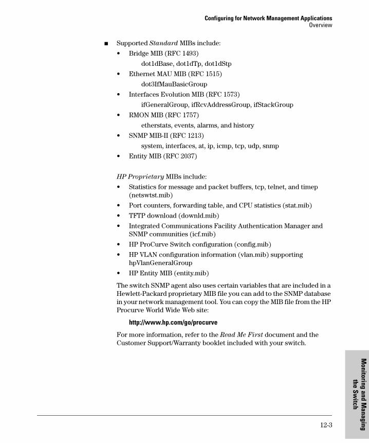
Configuring for Network Management ApplicationsOverview
Monitoring and M
anthe Sw
itch
� Supported Standard MIBs include:
• Bridge MIB (RFC 1493)
dot1dBase, dot1dTp, dot1dStp
• Ethernet MAU MIB (RFC 1515)
dot3IfMauBasicGroup
• Interfaces Evolution MIB (RFC 1573)
ifGeneralGroup, ifRcvAddressGroup, ifStackGroup
• RMON MIB (RFC 1757)
etherstats, events, alarms, and history
• SNMP MIB-II (RFC 1213)
system, interfaces, at, ip, icmp, tcp, udp, snmp
• Entity MIB (RFC 2037)
HP Proprietary MIBs include:
• Statistics for message and packet buffers, tcp, telnet, and timep (netswtst.mib)
• Port counters, forwarding table, and CPU statistics (stat.mib)
• TFTP download (downld.mib)
• Integrated Communications Facility Authentication Manager and SNMP communities (icf.mib)
• HP ProCurve Switch configuration (config.mib)
• HP VLAN configuration information (vlan.mib) supporting hpVlanGeneralGroup
• HP Entity MIB (entity.mib)
The switch SNMP agent also uses certain variables that are included in a Hewlett-Packard proprietary MIB file you can add to the SNMP database in your network management tool. You can copy the MIB file from the HP Procurve World Wide Web site:
http://www.hp.com/go/procurve
For more information, refer to the Read Me First document and the Customer Support/Warranty booklet included with your switch.
12-3
aging
Configuring for Network Management ApplicationsOverview
Mon
itori
ng a
nd M
anag
ing
the
Switc
h
Configuring for SNMP Access to the Switch
SNMP access requires an IP address and subnet mask configured on the switch. (See “IP Configuration” on page 7-3.) If you are using DHCP/Bootp to configure the switch, ensure that the DHCP/Bootp process provides the IP address. (See “DHCP/Bootp Operation” on page 7-10.)
Once an IP address has been configured, the general steps to configuring for SNMP access to the preceding features are:
1. From the Main menu, select
2. Switch Configuration . . .
6. SNMP Community Names
2. Configure the appropriate SNMP communities. (The “public” community exists by default and is used by HP’s network management applications.) (For more on configuring SNMP communities, see “Menu: Viewing and Configuring SNMP Communities” on page 12-5.)
3. Configure the appropriate trap receivers. (For more on configuring trap receivers, see “CLI: Configuring and Displaying Trap Receivers” on page 12-9.)
In some networks, authorized IP manager addresses are not used. In this case, all management stations using the correct community name may access the switch with the View and Access levels that have been set for that community. If you want to restrict access to one or more specific nodes, you can use the switch’s IP Authorized Manager feature. (See “Using Authorized IP Managers for Increased Management Security” on page 10-1.)
C a u t i o n Deleting the community named “public” disables many network management functions (such as auto-discovery, traffic monitoring, SNMP trap generation, and threshold setting). If security for network management is a concern, it is recommended that you change the write access for the “public” community to “Restricted”.
12-4
Configuring for Network Management ApplicationsOverview
Monitoring and M
anthe Sw
itch
SNMP Communities
SNMP Community Features
Use SNMP communities to restrict access to the switch by SNMP management stations by adding, editing, or deleting SNMP communities. You can configure up to five SNMP communities, each with either an operator-level or a manager-level view, and either restricted or unrestricted write access.
Using SNMP requires that the switch have an IP address and subnet mask compatible with your network.
C a u t i o n Deleting or changing the community named “public” prevents network man-agement applications (such as auto-discovery, traffic monitoring, SNMP trap generation, and threshold setting) from operating in the switch. (Changing or deleting the “public” name also generates an Event Log message.) If security for network management is a concern, it is recommended that you change the write access for the “public” community to “Restricted”.
Menu: Viewing and Configuring SNMP Communities
To View, Edit, or Add SNMP Communities:
1. From the Main Menu, Select:
2. Switch Configuration...6. SNMP Community Names
Feature Default Menu CLI Web
show community name n/a page 12-5 page 12-7 —
configure identity information none — page 12-7
configure community namesMIB view for a community name
(operator, manager)write access for defaultcommunity name
public
manager
unrestricted
page 12-5 " "
"
page 12-8 " " " "
—
12-5
aging
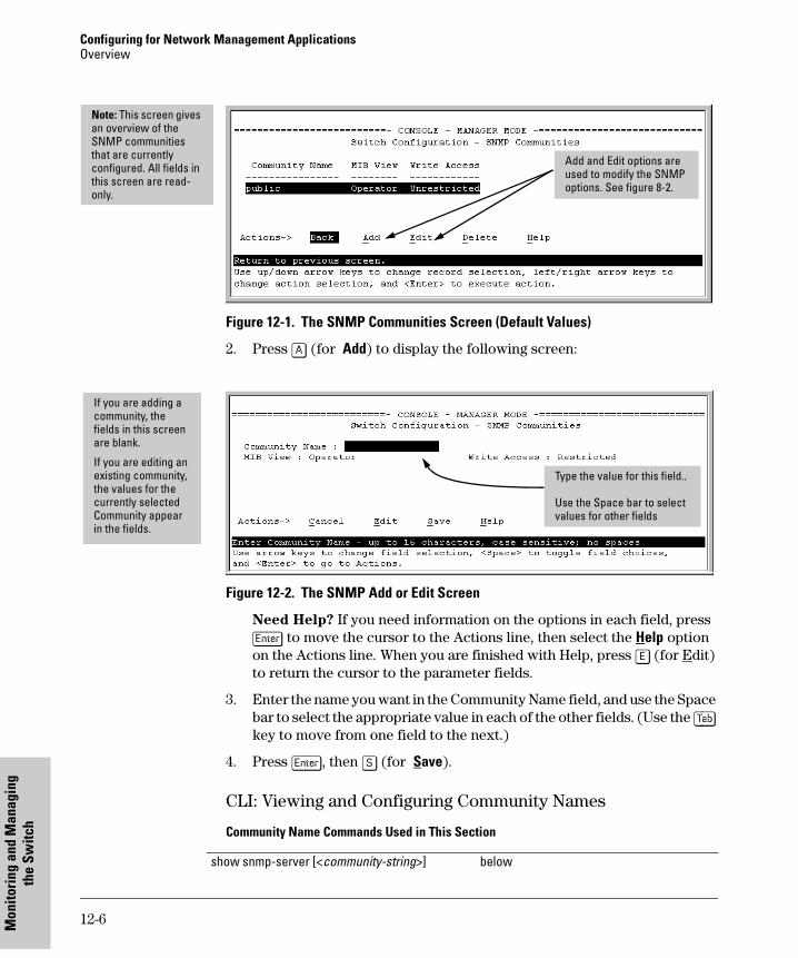
Configuring for Network Management ApplicationsOverview
Mon
itori
ng a
nd M
anag
ing
the
Switc
h
Figure 12-1. The SNMP Communities Screen (Default Values)
2. Press [A] (for Add) to display the following screen:
Figure 12-2. The SNMP Add or Edit Screen
Need Help? If you need information on the options in each field, press [Enter] to move the cursor to the Actions line, then select the Help option on the Actions line. When you are finished with Help, press [E] (for Edit) to return the cursor to the parameter fields.
3. Enter the name you want in the Community Name field, and use the Space bar to select the appropriate value in each of the other fields. (Use the [Tab] key to move from one field to the next.)
4. Press [Enter], then [S] (for Save).
CLI: Viewing and Configuring Community Names
Community Name Commands Used in This Section
Add and Edit options are used to modify the SNMP options. See figure 8-2.
Note: This screen gives an overview of the SNMP communities that are currently configured. All fields in this screen are read-only.
If you are adding a community, the fields in this screen are blank.
If you are editing an existing community, the values for the currently selected Community appear in the fields.
Type the value for this field..
Use the Space bar to select values for other fields
show snmp-server [<community-string>] below
12-6
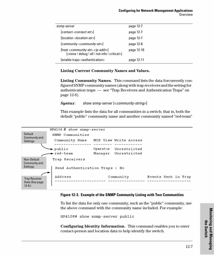
Configuring for Network Management ApplicationsOverview
Monitoring and M
anthe Sw
itch
Listing Current Community Names and Values.
Listing Community Names. This command lists the data forcurrently con-figured SNMP community names (along with trap receivers and the setting for authentication traps — see “Trap Receivers and Authentication Traps” on page 12-8).
Syntax: show snmp-server [<community-string>]
This example lists the data for all communities in a switch; that is, both the default "public" community name and another community named "red-team"
Figure 12-3. Example of the SNMP Community Listing with Two Communities
To list the data for only one community, such as the "public" community, use the above command with the community name included. For example:
HP4108# show snmp-server public
Configuring Identity Information. This command enables you to enter contact-person and location data to help identify the switch.
snmp-server page 12-7
[contact <contact-str>] page 12-7
[location <location-str>] page 12-7
[community <community-str>] page 12-8
[host <community-str> <ip-addr>] [<none | debug | all | not-info | critical>]
page 12-10
[enable traps <authentication> page 12-11
Default Community and Settings
Non-Default Community and Settings
Trap Receiver Data (See page 12-8.)
12-7
aging
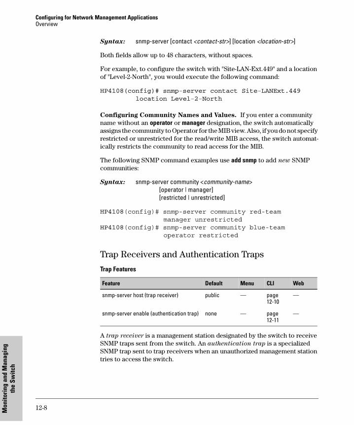
Configuring for Network Management ApplicationsOverview
Mon
itori
ng a
nd M
anag
ing
the
Switc
h
Syntax: snmp-server [contact <contact-str>] [location <location-str>]
Both fields allow up to 48 characters, without spaces.
For example, to configure the switch with "Site-LAN-Ext.449" and a location of "Level-2-North", you would execute the following command:
HP4108(config)# snmp-server contact Site-LANExt.449
location Level-2-North
Configuring Community Names and Values. If you enter a community name without an operator or manager designation, the switch automatically assigns the community to Operator for the MIB view. Also, if you do not specify restricted or unrestricted for the read/write MIB access, the switch automat-ically restricts the community to read access for the MIB.
The following SNMP command examples use add snmp to add new SNMP communities:
Syntax: snmp-server community <community-name>[operator | manager][restricted | unrestricted]
HP4108(config)# snmp-server community red-team manager unrestricted
HP4108(config)# snmp-server community blue-team operator restricted
Trap Receivers and Authentication Traps
Trap Features
A trap receiver is a management station designated by the switch to receive SNMP traps sent from the switch. An authentication trap is a specialized SNMP trap sent to trap receivers when an unauthorized management station tries to access the switch.
Feature Default Menu CLI Web
snmp-server host (trap receiver) public — page 12-10
—
snmp-server enable (authentication trap) none — page 12-11
—
12-8
Configuring for Network Management ApplicationsOverview
Monitoring and M
anthe Sw
itch
N o t e Fixed or "Well-Known" Traps: The Switch 4108GL automatically sends fixed traps (such as "coldStart", "warmStart", "linkDown", and "linkUp") to trap receivers using a public community name. These traps cannot be redirected to other communities. Thus, if you change or delete the default public com-munity name, these traps will be lost.
Thresholds: The switch automatically sends all messages resulting from thresholds to the network management station(s) that set the thresholds, regardless of the trap receiver configuration.
In the default configuration, there are no trap receivers configured, and the authentication trap feature is disabled. From the CLI you can configure up to ten SNMP trap receivers to receive SNMP traps from the switch. The switch can be configured to also send event log messages as traps if the following opotions are used with the snmp-server host command:
CLI: Configuring and Displaying Trap Receivers
Trap Receiver Commands Used in This Section
Using the CLI To List Current SNMP Trap Receivers.
This command lists the currently configured trap receivers and the setting for authentication traps (along with the current SNMP community name data — see “SNMP Communities” on page 12-5).
Syntax: show snmp-server
Event Level Description
None (default) Send no log messages.
All Send all log messages.
Not INFO Send the log messages that are not information-only.
Critical Send critical-level log messages.
Debug Reserved for HP-internal use.
show snmp-server below
snmp-server host <ip-addr> <community-name>[none | all | non-info| critical | debug]
page 12-10
snmp-server enable traps authentication page 12-10
12-9
aging
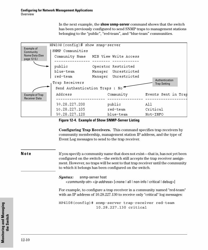
Configuring for Network Management ApplicationsOverview
Mon
itori
ng a
nd M
anag
ing
the
Switc
h
In the next example, the show snmp-server command shows that the switch has been previously configured to send SNMP traps to management stations belonging to the “public”, “red-team”, and “blue-team” communities.
Figure 12-4. Example of Show SNMP-Server Listing
Configuring Trap Receivers. This command specifies trap receivers by community membership, management station IP address, and the type of Event Log messages to send to the trap receiver.
N o t e If you specify a community name that does not exist—that is, has not yet been configured on the switch—the switch still accepts the trap receiver assign-ment. However, no traps will be sent to that trap receiver until the community to which it belongs has been configured on the switch.
Syntax: snmp-server host <community-str> <ip-address> [<none | all | non-info | critical | debug>]
For example, to configure a trap receiver in a community named "red-team" with an IP address of 10.28.227.130 to receive only "critical" log messages:
HP4108(config)# snmp-server trap-receiver red-team
10.28.227.130 critical
Example of Community Name Data (See page 12-5.)
Example of Trap Receiver Data
Authentication Trap Setting
12-10
Configuring for Network Management ApplicationsOverview
Monitoring and M
anthe Sw
itch
N o t e If you do not specify the event level ([<none | all | non-info | critical | debug>]) then the switchwill not send event log messages as traps. "Well-Known" traps and threshold traps (if configured) will still be sent..
Using the CLI To Enable Authentication Traps
If this feature is enabled, an authentication trap is sent to the configured trap receiver(s) if a management station attempts an unauthorized access of the switch. Check the event log in the console interface to help determine why the authentication trap was sent. (Refer to “Using the Event Log To Identify Problem Sources” on page “Using the Event Log To Identify Problem Sources” on page 18-16.)
N o t e For this feature to operate, one or more trap receivers must be configured on the switch. See “CLI: Configuring and Displaying Trap Receivers” on page 12-9.
Using the CLI To Enable Authentication Traps.
Syntax: snmp-server trap authentication
HP4108(config)# snmp-server trap authentication
Advanced Management: RMON
The switch supports RMON (Remote Monitoring) on all connected network segments. This allows for troubleshooting and optimizing your network.
The following RMON groups are supported:
� Ethernet Statistics (except the numbers of packets of different frame sizes)� Alarm� History (of the supported Ethernet statistics)� Event
The RMON agent automatically runs in the switch. Use the RMON manage-ment station on your network to enable or disable specific RMON traps and events. Note that you can access the Ethernet statistics, Alarm, and Event groups from the HP TopTools for Hubs & Switches network management software. For more on TopTools, see the "Read Me First" document shipped with your switch and also available on HP’s ProCurve website at
http://www.hp.com/go/procurve
12-11
aging
Configuring for Network Management ApplicationsCDP
Mon
itori
ng a
nd M
anag
ing
the
Switc
h
CDP
CDP Features
Introduction
In a Switch 4108GL, CDP-v1 (Cisco Discovery Protocol, version 1) provides data that aids SNMP-based network mapping utilities designed to discover devices running CDP in a network. To make this data available, the switch transmits information about itself via CDP packets to adjacent devices, and also receives and stores information about adjacent devices running CDP. This enables each CDP device to receive and maintain identity data on each of its CDP neighbors and pass this information off to an SNMP utility designed to query the CDP area of the device’s MIB.
NoteTo take advantage of CDP in Switch 4108GL, you should have a working knowledge of SNMP operation and an SNMP utility capable of polling the switches for CDP data. HP’s implementation of CDP places specific data into the switch’s Management Information Base (MIB). However, retrieval of this data for network mapping is dependent on the operation of your SNMP utility. Refer to the documentation provided with the utility.
Feature Default Menu CLI Web
view the switch’s CDP configuration n/a — page 12-19 —
view the switch’s CDP Neighbors table n/a — page 12-19 —
clear (reset) the CDP Neighbors table n/a — page 12-20 —
enable or disable CDP on the switch enabled — page 12-21 —
enable or disable CDP operation on an individual port
enabled — page 12-22 —
change the transmit interval for the switch’s CDP packets
60 seconds — page 12-22 —
change the hold time (time-to-live for CDP packets the switch generates)
180 seconds — page 12-23 —
12-12
Configuring for Network Management ApplicationsCDP
Monitoring and M
anthe Sw
itch
An SNMP utility can progressively discover CDP devices in a network by:
1. Reading a given device’s CDP Neighbor table (in the Management Infor-mation Base, or MIB) to learn about other, neighbor CDP devices
2. Using the information learned in step 1 to go to and read the neighbor devices’ CDP Neighbors tables to learn about additional CDP devices, and so on
This section describes CDP operation in a Switch 4108GL. For information on how to use an SNMP utility to retrieve the CDP information from the switch’s CDP Neighbors table (in the switch’s MIB), refer to the documentation provided with the particular SNMP utility. For information on the object identifiers in the CDP MIB, see “CDP Neighbor Data and MIB Objects” on page 25.
CDP Terminology
� CDP Device: A switch, server, router, workstation, or other device running CDP.
� CDP-Aware: A device that has CDP in its operating code (with CDP either enabled or disabled in that device).
� CDP-Disabled: A CDP-aware device on which CDP is currently disabled.
� Non-CDP Device: A device that does not have CDP in its operating code.
� CDP Neighbor: A CDP device that is either directly connected to another CDP device or connected to that device by a non-CDP device, such as some hubs.
General CDP Operation
The switch stores information about adjacent CDP devices in a CDP Neigh-
bors table maintained in the switch’s MIB (Management Information Base). This data is available to SNMP-based applications designed to read CDP data from the MIB. For example:
12-13
aging
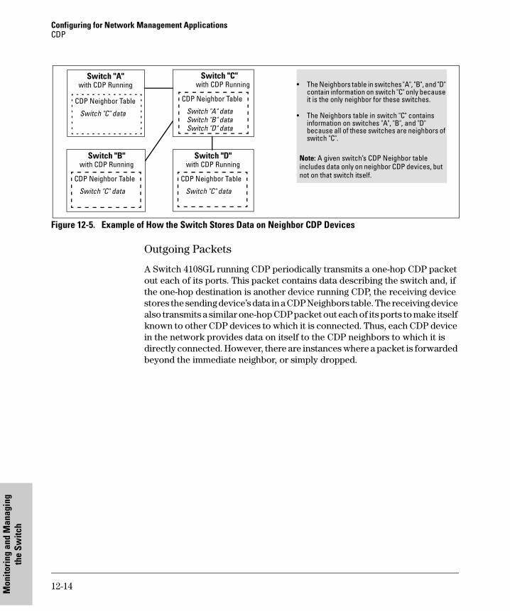
Configuring for Network Management ApplicationsCDP
Mon
itori
ng a
nd M
anag
ing
the
Switc
h
Figure 12-5. Example of How the Switch Stores Data on Neighbor CDP Devices
Outgoing Packets
A Switch 4108GL running CDP periodically transmits a one-hop CDP packet out each of its ports. This packet contains data describing the switch and, if the one-hop destination is another device running CDP, the receiving device stores the sending device’s data in a CDP Neighbors table. The receiving device also transmits a similar one-hop CDP packet out each of its ports to make itself known to other CDP devices to which it is connected. Thus, each CDP device in the network provides data on itself to the CDP neighbors to which it is directly connected. However, there are instances where a packet is forwarded beyond the immediate neighbor, or simply dropped.
Switch "A" with CDP Running • The Neighbors table in switches "A", "B", and "D"
contain information on switch "C" only because it is the only neighbor for these switches.
• The Neighbors table in switch "C" contains information on switches "A", "B", and "D" because all of these switches are neighbors of switch "C".
Note: A given switch’s CDP Neighbor table includes data only on neighbor CDP devices, but not on that switch itself.
CDP Neighbor Table
Switch "C" data
Switch "B" with CDP Running
CDP Neighbor Table
Switch "C" data
Switch "C" with CDP Running
CDP Neighbor Table
Switch "A" data Switch "B" data Switch "D" data
Switch "D" with CDP Running
CDP Neighbor Table
Switch "C" data
12-14
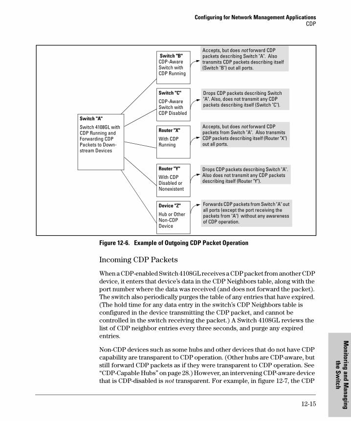
Configuring for Network Management ApplicationsCDP
Monitoring and M
anthe Sw
itch
Figure 12-6. Example of Outgoing CDP Packet Operation
Incoming CDP Packets
When a CDP-enabled Switch 4108GL receives a CDP packet from another CDP device, it enters that device’s data in the CDP Neighbors table, along with the port number where the data was received (and does not forward the packet). The switch also periodically purges the table of any entries that have expired. (The hold time for any data entry in the switch’s CDP Neighbors table is configured in the device transmitting the CDP packet, and cannot be controlled in the switch receiving the packet.) A Switch 4108GL reviews the list of CDP neighbor entries every three seconds, and purge any expired entries.
Non-CDP devices such as some hubs and other devices that do not have CDP capability are transparent to CDP operation. (Other hubs are CDP-aware, but still forward CDP packets as if they were transparent to CDP operation. See “CDP-Capable Hubs” on page 28.) However, an intervening CDP-aware device that is CDP-disabled is not transparent. For example, in figure 12-7, the CDP
Switch "A"
Switch 4108GL with CDP Running and Forwarding CDP Packets to Down- stream Devices
Switch "B" CDP-Aware Switch with CDP Running
Switch "C"
CDP-Aware Switch with CDP Disabled
Router "Y"
With CDP Disabled or Nonexistent
Device "Z"
Hub or Other Non-CDP Device
Router "X"
With CDP Running
Accepts, but does not forward CDP packets describing Switch "A". Also transmits CDP packets describing itself (Switch "B") out all ports.
Drops CDP packets describing Switch "A". Also does not transmit any CDP packets describing itself (Router "Y").
Forwards CDP packets from Switch "A" out all ports (except the port receiving the packets from "A") without any awareness of CDP operation.
Drops CDP packets describing Switch "A". Also, does not transmit any CDP packets describing itself (Switch "C").
Accepts, but does not forward CDP packets from Switch "A". Also transmits CDP packets describing itself (Router "X") out all ports.
12-15
aging
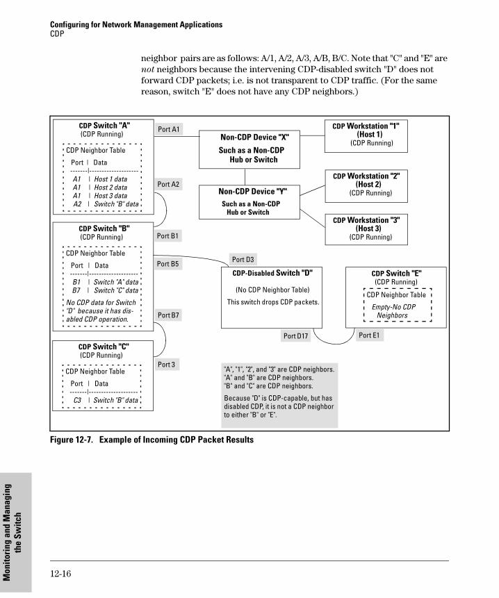
Configuring for Network Management ApplicationsCDP
Mon
itori
ng a
nd M
anag
ing
the
Switc
h
neighbor pairs are as follows: A/1, A/2, A/3, A/B, B/C. Note that "C" and "E" are not neighbors because the intervening CDP-disabled switch "D" does not forward CDP packets; i.e. is not transparent to CDP traffic. (For the same reason, switch "E" does not have any CDP neighbors.)
Figure 12-7. Example of Incoming CDP Packet Results
CDP Switch "A" (CDP Running)
CDP Neighbor Table
Port | Data -------|-------------------- A1 | Host 1 data A1 | Host 2 data A1 | Host 3 data A2 | Switch "B" data
CDP Workstation "1" (Host 1) (CDP Running)
Non-CDP Device "X"
Such as a Non-CDP Hub or Switch
CDP Workstation "2" (Host 2) (CDP Running) Non-CDP Device "Y"
Such as a Non-CDP Hub or Switch
CDP Workstation "3" (Host 3) (CDP Running)
CDP Switch "B" (CDP Running)
CDP Neighbor Table
Port | Data -------|-------------------- B1 | Switch "A" data B7 | Switch "C" data
No CDP data for Switch "D" because it has dis- abled CDP operation.
Port A1
Port B1
CDP Switch "C" (CDP Running)
CDP Neighbor Table
Port | Data -------|-------------------- C3 | Switch "B" data
Port 3
Port B7
CDP-Disabled Switch "D" (No CDP Neighbor Table)
This switch drops CDP packets.
CDP Switch "E" (CDP Running)
CDP Neighbor Table
Empty-No CDP Neighbors
Port A2
Port D3
Port D17 Port E1
"A", "1", "2", and "3" are CDP neighbors."A" and "B" are CDP neighbors."B" and "C" are CDP neighbors.
Because "D" is CDP-capable, but has disabled CDP, it is not a CDP neighbor to either "B" or "E".
Port B5
12-16
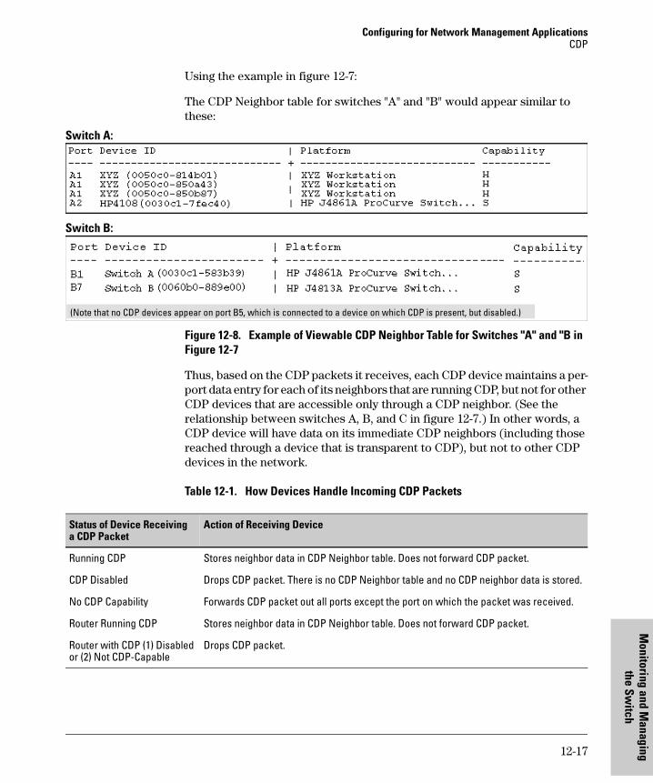
Configuring for Network Management ApplicationsCDP
Monitoring and M
anthe Sw
itch
Using the example in figure 12-7:
The CDP Neighbor table for switches "A" and "B" would appear similar to these:
Switch A:
Switch B:
Figure 12-8. Example of Viewable CDP Neighbor Table for Switches "A" and "B in Figure 12-7
Thus, based on the CDP packets it receives, each CDP device maintains a per-port data entry for each of its neighbors that are running CDP, but not for other CDP devices that are accessible only through a CDP neighbor. (See the relationship between switches A, B, and C in figure 12-7.) In other words, a CDP device will have data on its immediate CDP neighbors (including those reached through a device that is transparent to CDP), but not to other CDP devices in the network.
Table 12-1. How Devices Handle Incoming CDP Packets
(Note that no CDP devices appear on port B5, which is connected to a device on which CDP is present, but disabled.)
Status of Device Receivinga CDP Packet
Action of Receiving Device
Running CDP Stores neighbor data in CDP Neighbor table. Does not forward CDP packet.
CDP Disabled Drops CDP packet. There is no CDP Neighbor table and no CDP neighbor data is stored.
No CDP Capability Forwards CDP packet out all ports except the port on which the packet was received.
Router Running CDP Stores neighbor data in CDP Neighbor table. Does not forward CDP packet.
Router with CDP (1) Disabled or (2) Not CDP-Capable
Drops CDP packet.
12-17
aging
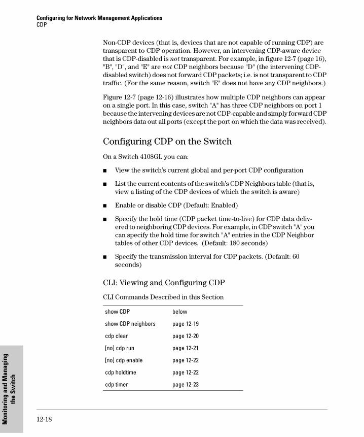
Configuring for Network Management ApplicationsCDP
Mon
itori
ng a
nd M
anag
ing
the
Switc
h
Non-CDP devices (that is, devices that are not capable of running CDP) are transparent to CDP operation. However, an intervening CDP-aware device that is CDP-disabled is not transparent. For example, in figure 12-7 (page 16), "B", "D", and "E" are not CDP neighbors because "D" (the intervening CDP-disabled switch) does not forward CDP packets; i.e. is not transparent to CDP traffic. (For the same reason, switch "E" does not have any CDP neighbors.)
Figure 12-7 (page 12-16) illustrates how multiple CDP neighbors can appear on a single port. In this case, switch "A" has three CDP neighbors on port 1 because the intervening devices are not CDP-capable and simply forward CDP neighbors data out all ports (except the port on which the data was received).
Configuring CDP on the Switch
On a Switch 4108GL you can:
� View the switch’s current global and per-port CDP configuration
� List the current contents of the switch’s CDP Neighbors table (that is, view a listing of the CDP devices of which the switch is aware)
� Enable or disable CDP (Default: Enabled)
� Specify the hold time (CDP packet time-to-live) for CDP data deliv-ered to neighboring CDP devices. For example, in CDP switch "A" you can specify the hold time for switch "A" entries in the CDP Neighbor tables of other CDP devices. (Default: 180 seconds)
� Specify the transmission interval for CDP packets. (Default: 60 seconds)
CLI: Viewing and Configuring CDP
CLI Commands Described in this Section
show CDP below
show CDP neighbors page 12-19
cdp clear page 12-20
[no] cdp run page 12-21
[no] cdp enable page 12-22
cdp holdtime page 12-22
cdp timer page 12-23
12-18
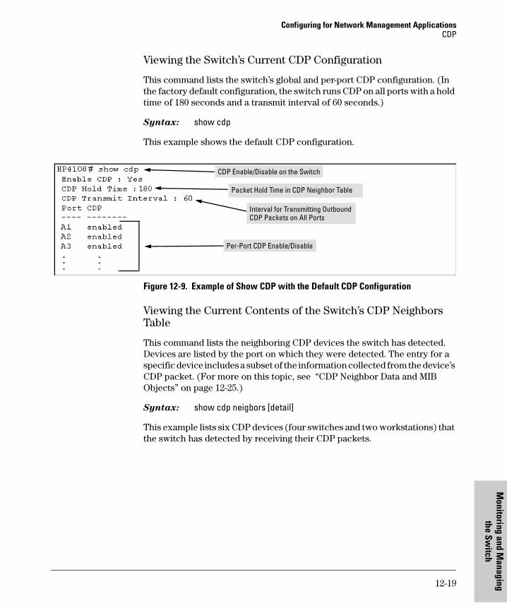
Configuring for Network Management ApplicationsCDP
Monitoring and M
anthe Sw
itch
Viewing the Switch’s Current CDP Configuration
This command lists the switch’s global and per-port CDP configuration. (In the factory default configuration, the switch runs CDP on all ports with a hold time of 180 seconds and a transmit interval of 60 seconds.)
Syntax: show cdp
This example shows the default CDP configuration.
Figure 12-9. Example of Show CDP with the Default CDP Configuration
Viewing the Current Contents of the Switch’s CDP Neighbors Table
This command lists the neighboring CDP devices the switch has detected. Devices are listed by the port on which they were detected. The entry for a specific device includes a subset of the information collected from the device’s CDP packet. (For more on this topic, see “CDP Neighbor Data and MIB Objects” on page 12-25.)
Syntax: show cdp neigbors [detail]
This example lists six CDP devices (four switches and two workstations) that the switch has detected by receiving their CDP packets.
CDP Enable/Disable on the Switch
Packet Hold Time in CDP Neighbor Table
Interval for Transmitting Outbound CDP Packets on All Ports
Per-Port CDP Enable/Disable
12-19
aging
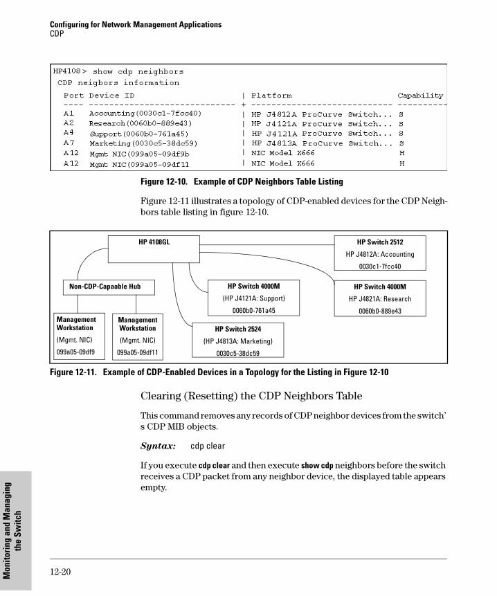
Configuring for Network Management ApplicationsCDP
Mon
itori
ng a
nd M
anag
ing
the
Switc
h
Figure 12-10. Example of CDP Neighbors Table Listing
Figure 12-11 illustrates a topology of CDP-enabled devices for the CDP Neigh-bors table listing in figure 12-10.
Figure 12-11. Example of CDP-Enabled Devices in a Topology for the Listing in Figure 12-10
Clearing (Resetting) the CDP Neighbors Table
This command removes any records of CDP neighbor devices from the switch’ s CDP MIB objects.
Syntax: cdp clear
If you execute cdp clear and then execute show cdp neighbors before the switch receives a CDP packet from any neighbor device, the displayed table appears empty.
HP 4108GL
HP Switch 2524
(HP J4813A: Marketing)
0030c5-38dc59
Management Workstation
(Mgmt. NIC)
099a05-09df9
HP Switch 4000M
HP J4821A: Research
0060b0-889e43
HP Switch 4000M
(HP J4121A: Support)
0060b0-761a45
HP Switch 2512
HP J4812A: Accounting
0030c1-7fcc40
Management Workstation
(Mgmt. NIC)
099a05-09df11
Non-CDP-Capaable Hub
12-20
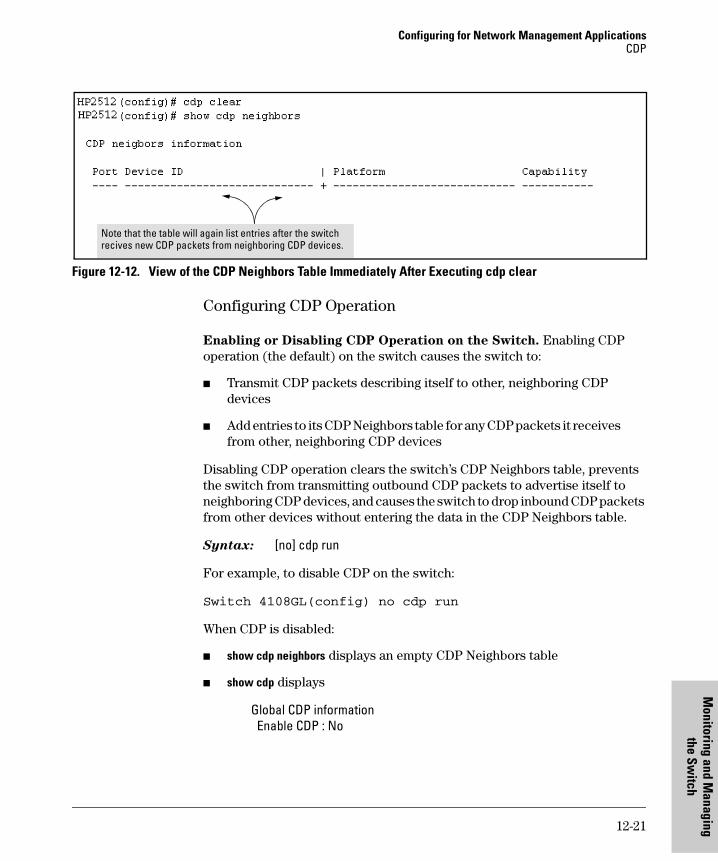
Configuring for Network Management ApplicationsCDP
Monitoring and M
anthe Sw
itch
Figure 12-12. View of the CDP Neighbors Table Immediately After Executing cdp clear
Configuring CDP Operation
Enabling or Disabling CDP Operation on the Switch. Enabling CDP operation (the default) on the switch causes the switch to:
� Transmit CDP packets describing itself to other, neighboring CDP devices
� Add entries to its CDP Neighbors table for any CDP packets it receives from other, neighboring CDP devices
Disabling CDP operation clears the switch’s CDP Neighbors table, prevents the switch from transmitting outbound CDP packets to advertise itself to neighboring CDP devices, and causes the switch to drop inbound CDP packets from other devices without entering the data in the CDP Neighbors table.
Syntax: [no] cdp run
For example, to disable CDP on the switch:
Switch 4108GL(config) no cdp run
When CDP is disabled:
� show cdp neighbors displays an empty CDP Neighbors table
� show cdp displays
Global CDP information Enable CDP : No
Note that the table will again list entries after the switch recives new CDP packets from neighboring CDP devices.
12-21
aging
Configuring for Network Management ApplicationsCDP
Mon
itori
ng a
nd M
anag
ing
the
Switc
h
Enabling or Disabling CDP Operation on Individual Ports. In the factory-default configuration, the switch has all ports enabled and transmit-ting CDP packets. Disabling CDP on a port prevents that port from sending outbound CDP packets and causes it to drop inbound CDP packets without recording their data in the CDP Neighbors table. Suppose, for example, that switches "A" and "B" in figure 12-12-13 are running CDP, and that port A1 on switch "A" is connected to port B5 on switch "B". If you disable CDP on port A1 of switch "A", then switch "B" will no longer receive CDP packets from switch "A" and switch "A" will drop the CDP packets it receives from switch "B".
Figure 12-13. Example of Disabling CDP on an Individual Port
(The switch "A" entry in the switch "B" CDP Neighbors table remains until the cdp holdtime (time-to-live; set in switch "A") expires. Until then, the show cdp neighbors command continues to list switch "A" on port B5 of switch "B".)
Syntax: [no] cdp enable <[ethernet] port-list>
For example, to disable CDP on port A1 of a Switch 4108GL:
Switch 4108GL(config) no cdp enable a1
Changing the Transmission Interval for Outbound CDP Packets. The default interval the switch uses to transmit CDP packets describing itself to other, neighbor devices is 60 seconds. This command changes the interval.
Syntax: cdp timer <5 . . 254>
Switch "A"CDP Enabled on Port A1
CDP Neighbor Table
Port | Data------|------------------ A1 | Switch "B" data
Switch "B"CDP Enabled on Port B5
CDP Neighbor Table
Port | Data------|------------------ B5 | Switch "A" data
CDP Enabled on both ends of the link between "A" and "B".
Port A1
Port B5
Switch "A"CDP Disabled on Port A1
CDP Neighbor Table
-Empty for port A1-
Switch "B"CDP Enabled on Port B5
CDP Neighbor Table
- Empty for Port B5 -
CDP disabled on port A1 of switch "A" (but enabled on port B5 of switch "B".
Port A1
Port B5
12-22
Configuring for Network Management ApplicationsCDP
Monitoring and M
anthe Sw
itch
For example, if the switch’s transmit interval for CDP packets was set to a non-default value, you would use this command to reset it to one minute:
Switch 4108GL(config) cdp timer 60
Changing the Hold Time (CDP Packet Time-To-Live) for a Switch’s
CDP Packet Information. The default hold time for the switch’s CDP packet information in the CDP Neighbors table of another CDP device is 180 seconds (range: 5 - 254). This parameter is controlled in the transmitting switch, and applies to all outbound CDP packets the switch transmits.
Syntax: cdp holdtime <5 . . 254>
For example, to configure a switch’s outbound CDP packets to live for one minute in the CDP Neighbors table of neighboring CDP devices:
Switch 4108GL(config) cdp holdtime 60
Effect of Spanning Tree (STP) On CDP Packet Transmission
If STP has blocked a port on the switch, that port does not transmit CDP packets. However, the port still receives CDP packets if the device on the other end of the link has CDP enabled. Thus, for example, if switch "A" has two ports linked to switch "B" (which is a CDP neighbor and also the STP root device) and STP blocks traffic on one port and forwards traffic on the other:
Figure 12-14. Example of STP Effect on CDP Packet Transmission
Switch "A" CDP Enabled
CDP Neighbor Table
Port | Data------|------------------ A3 | Switch "B"data
C5 | Switch "B" data
Switch "B" CDP Enabled
STP Root Device
CDP Neighbor Table
Port | Data------|------------------ B1 | Switch "A" data
STP block on port C5 of switch "A" blocks outbound transmission of CDP packets from switch "A", but does not block inbound packets to switch "A" from switch "B".
Port A3
Port C5
CDP Packets from Switch "A" to Switch "B"
Port B1
Port D8
CDP Packets from Switch "B" to Switch "A"
12-23
aging
Configuring for Network Management ApplicationsCDP
Mon
itori
ng a
nd M
anag
ing
the
Switc
h
� Switch "A" sends outbound CDP packets on the forwarding link, and the switch "B" CDP Neighbors table shows switch "A" on only one port.
� Switch "B" sends outbound CDP packets on both links, and the switch "A" CDP Neighbors table shows switch "B" on both ports.
To summarize, in a CDP neighbor pair running STP with redundant links, if one of the switches is the STP root, it transmits CDP packets out all ports connecting the two switches, while the other switch transmits CDP packets out only the unblocked port. Thus, the STP root switch will appear on multiple ports in the non-root switch’s CDP Neighbors table, while the non-root switch will appear on only one port in the root switch’s CDP Neighbors table.
How the Switch Selects the IP Address To Include in Outbound CDP Packets
A switch with CDP enabled uses the following prioritized criteria to determine which IP address to include in its outbound CDP packets:
1. If only one VLAN on theport has an IP address, the switch uses that IP address.
2. If the Primary VLAN on the port has an IP address, the switch uses the Primary VLAN IP address.
3. If 1 and 2 do not apply, then the switch determines which VLANs on the port have IP addresses and uses the IP address of the VLAN with the lowest VID (VLAN Identification number) in this group.
4. If a CDP switch does not detect an IP address on the connecting port of a CDP neighbor, then the loopback IP address is used (127.0.0.1).
For example, in figure 12-12-15, port A1 on CDP switch "X" is connected to port C5 on CDP neighbor switch "Y", with the indicated VLAN configuration on port C5:
12-24
Configuring for Network Management ApplicationsCDP
Monitoring and M
anthe Sw
itch
Figure 12-15. Example of IP Address Selection when the CDP Neighbor Has Multiple VLANs with IP Addresses
CDP Neighbor Data and MIB Objects
The switch places the data received from inbound CDP packets into its MIB (Management Information Base). This data is available in three ways:
� Using the switch’s show cdp neighbors command to display a subset of Neighbor data
� Using the walkmib command to display a listing of the CDP MIB objects
� Electronically, using an SNMP utility designed to search the MIB for CDP data
As shown under “Viewing the Current Contents of the Switch’s CDP Neighbors Table” on page 12-19, you can list a subset of data for each CDP device currently found in the switch’s CDP Neighbors table. Table 12-2, "CDP Neighbors Data", describes the CDP Neighbor data set available in the Switch 4108GL.
Switch "X" CDP Enabled on Port A1
CDP Neighbor Table
Port | Data------|------------------ A1 | 10.28.227.103
Switch "Y" CDP Enabled on Port C5
CDP Neighbor Table
Port | Data------|------------------ C5 | Switch "X" data
Port A1
Port C5
VLAN Membership in Port C5 of Switch "Y" VID IP Address?DEFAULT_VLAN (Primary VLAN) 1 NoBlue_VLAN 200 10.28.227.103Red VLAN 300 10.28.227.88
Thus, CDP switch "X" detects CDP switch "Y" on port A1 and shows 10.28.227.103 in its CDP table entry because in CDP switch "Y" the Primary VLAN does not have an IP address and the Blue_VLAN has a lower VID than the Red_VLAN.
12-25
aging
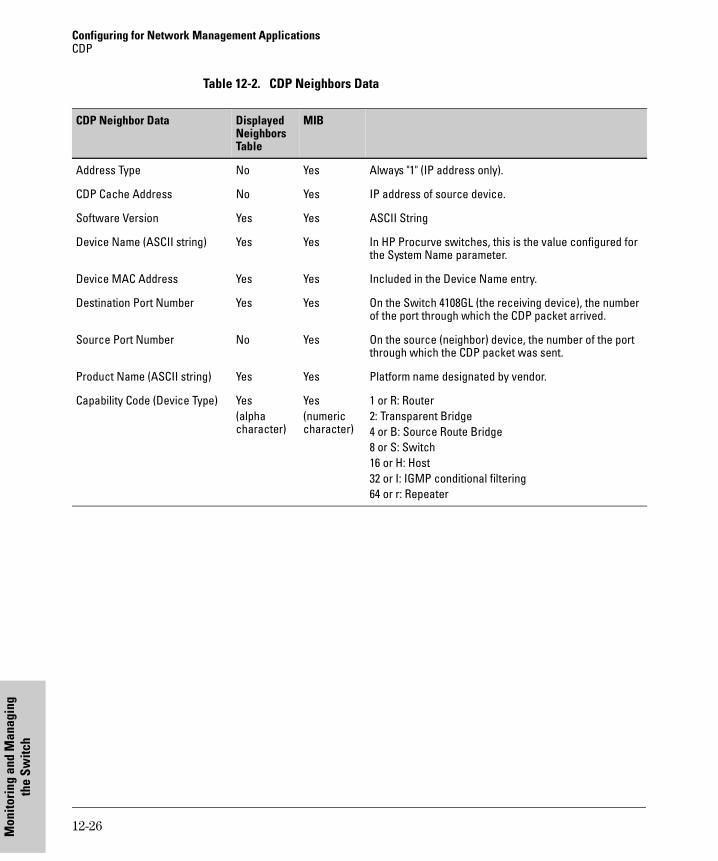
Configuring for Network Management ApplicationsCDP
Mon
itori
ng a
nd M
anag
ing
the
Switc
h
Table 12-2. CDP Neighbors Data
CDP Neighbor Data DisplayedNeighbors Table
MIB
Address Type No Yes Always "1" (IP address only).
CDP Cache Address No Yes IP address of source device.
Software Version Yes Yes ASCII String
Device Name (ASCII string) Yes Yes In HP Procurve switches, this is the value configured for the System Name parameter.
Device MAC Address Yes Yes Included in the Device Name entry.
Destination Port Number Yes Yes On the Switch 4108GL (the receiving device), the number of the port through which the CDP packet arrived.
Source Port Number No Yes On the source (neighbor) device, the number of the port through which the CDP packet was sent.
Product Name (ASCII string) Yes Yes Platform name designated by vendor.
Capability Code (Device Type) Yes(alphacharacter)
Yes(numeric character)
1 or R: Router2: Transparent Bridge4 or B: Source Route Bridge8 or S: Switch16 or H: Host32 or I: IGMP conditional filtering64 or r: Repeater
12-26
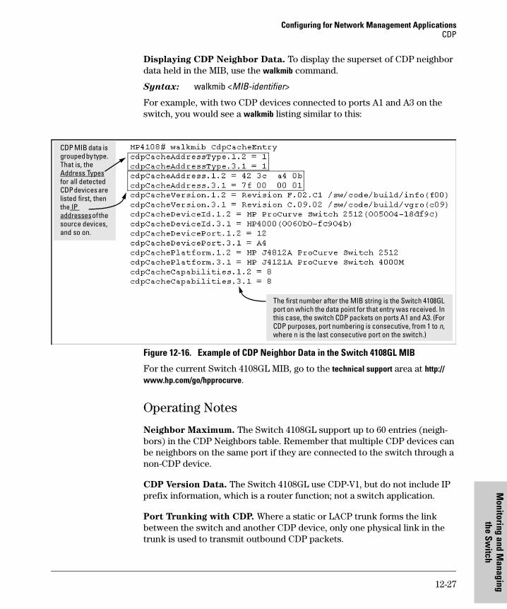
Configuring for Network Management ApplicationsCDP
Monitoring and M
anthe Sw
itch
Displaying CDP Neighbor Data. To display the superset of CDP neighbor data held in the MIB, use the walkmib command.
Syntax: walkmib <MIB-identifier>
For example, with two CDP devices connected to ports A1 and A3 on the switch, you would see a walkmib listing similar to this:
Figure 12-16. Example of CDP Neighbor Data in the Switch 4108GL MIB
For the current Switch 4108GL MIB, go to the technical support area at http://www.hp.com/go/hpprocurve.
Operating Notes
Neighbor Maximum. The Switch 4108GL support up to 60 entries (neigh-bors) in the CDP Neighbors table. Remember that multiple CDP devices can be neighbors on the same port if they are connected to the switch through a non-CDP device.
CDP Version Data. The Switch 4108GL use CDP-V1, but do not include IP prefix information, which is a router function; not a switch application.
Port Trunking with CDP. Where a static or LACP trunk forms the link between the switch and another CDP device, only one physical link in the trunk is used to transmit outbound CDP packets.
The first number after the MIB string is the Switch 4108GL port on which the data point for that entry was received. In this case, the switch CDP packets on ports A1 and A3. (For CDP purposes, port numbering is consecutive, from 1 to n, where n is the last consecutive port on the switch.)
CDP MIB data is grouped by type. That is, the Address Types for all detected CDP devices are listed first, then the IP addresses of the source devices, and so on.
12-27
aging
Configuring for Network Management ApplicationsCDP
Mon
itori
ng a
nd M
anag
ing
the
Switc
h
CDP-Capable Hubs. Some hubs are capable of running CDP, but also forward CDP packets as if the hub itself were transparent to CDP. Such hubs will appear in the switch’s CDP Neighbor table and will also maintain a CDP neighbor table similar to that for switches. For more information, refer to the documentation provided for the specific hub.
Troubleshooting CDP Operation. Turn to “Using the Event Log To Identify Problem Sources” on page 18-16.
12-28
HP Procurve Stack
Managem
ent
13
HP Procurve Stack Management
Chapter Contents
Overview . . . . . . . . . . . . . . . . . . . . . . . . . . . . . . . . . . . . . . . . . . . . . . . . . . . . 13-3
HP Procurve Stack Management . . . . . . . . . . . . . . . . . . . . . . . . . . . . . . 13-4
Which Devices Support Stacking? . . . . . . . . . . . . . . . . . . . . . . . . . . . . 13-5
Components of HP Procurve Stack Management . . . . . . . . . . . . . . . . 13-6
General Stacking Operation . . . . . . . . . . . . . . . . . . . . . . . . . . . . . . . . . . 13-6
Operating Rules for Stacking . . . . . . . . . . . . . . . . . . . . . . . . . . . . . . . . . 13-7General Rules . . . . . . . . . . . . . . . . . . . . . . . . . . . . . . . . . . . . . . . . . . 13-7Specific Rules . . . . . . . . . . . . . . . . . . . . . . . . . . . . . . . . . . . . . . . . . . 13-8
Overview of Configuring and Bringing Up a Stack . . . . . . . . . . . . . . 13-10General Steps for Creating a Stack . . . . . . . . . . . . . . . . . . . . . . . 13-12
Using the Menu Interface To View Stack Status and Configure Stacking . . . . . . . . . . . . . . . . . . . . . . . . . . . . . . . . . . . . . . . . 13-14
Using the Menu Interface To View and Configure a Commander Switch . . . . . . . . . . . . . . . . . . . . . . . . . . . . . . . . . . . . 13-14Using the Menu To Manage a Candidate Switch . . . . . . . . . . . . 13-16
Using the Commander To Manage The Stack . . . . . . . . . . . . . . . . . . 13-18Using the Commander To Access Member Switches for Configuration Changes and Monitoring Traffic . . . . . . . . . . . . . 13-25Converting a Commander or Member to a Member of Another Stack . . . . . . . . . . . . . . . . . . . . . . . . . . . . . . . . . . . . . . . . . 13-26
Monitoring Stack Status . . . . . . . . . . . . . . . . . . . . . . . . . . . . . . . . . . . . 13-27
Using the CLI To View Stack Status and Configure Stacking . . . . . 13-31Using the CLI To View Stack Status . . . . . . . . . . . . . . . . . . . . . . 13-33Using the CLI To Configure a Commander Switch . . . . . . . . . . 13-35Adding to a Stack or Moving Switches Between Stacks . . . . . . 13-37Using the CLI To Remove a Member from a Stack . . . . . . . . . . 13-42Using the CLI To Access Member Switches for Configuration Changes and Traffic Monitoring . . . . . . . . . . . . . . . . . . . . . . . . . . 13-44
SNMP Community Operation in a Stack . . . . . . . . . . . . . . . . . . . . . . 13-45
Using the CLI To Disable or Re-Enable Stacking . . . . . . . . . . . . . . . 13-46
13-1

HP Procurve Stack Management Chapter Contents
HP
Proc
urve
Sta
ck
Man
agem
ent
Transmission Interval . . . . . . . . . . . . . . . . . . . . . . . . . . . . . . . . . . . . . . 13-46
Stacking Operation with Multiple VLANs Configured . . . . . . . . . . . 13-46
Web: Viewing and Configuring Stacking . . . . . . . . . . . . . . . . . . . . . . 13-47
Status Messages . . . . . . . . . . . . . . . . . . . . . . . . . . . . . . . . . . . . . . . . . . . 13-48
13-2
HP Procurve Stack ManagementOverview
HP Procurve Stack
Managem
ent
OverviewThis chapter describes how to use your network to stack switches without the need for any specialized cabling—page 13-4.
For general information on how to use the switch’s built-in interfaces, see:
� Chapter 2, “Using the Menu Interface”
� Chapter 3, “Using the Command Line Interface (CLI)”
� Chapter 4, “Using the HP Web Browser Interface
� Chapter 5, “Switch Memory and Configuration”
13-3
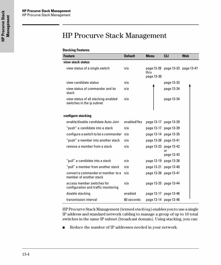
HP Procurve Stack Management HP Procurve Stack Management
HP
Proc
urve
Sta
ck
Man
agem
ent
HP Procurve Stack Management
Stacking Features
HP Procurve Stack Management (termed stacking) enables you to use a single IP address and standard network cabling to manage a group of up to 16 total switches in the same IP subnet (broadcast domain). Using stacking, you can:
� Reduce the number of IP addresses needed in your network.
Feature Default Menu CLI Web
view stack status
view status of a single switch n/a page 13-28 thru page 13-30
page 13-33 page 13-47
view candidate status n/a page 13-33
view status of commander and its stack
n/a page 13-34
view status of all stacking-enabled switches in the ip subnet
n/a page 13-34
configure stacking
enable/disable candidate Auto-Join enabled/Yes page 13-17 page 13-39
“push” a candidate into a stack n/a page 13-17 page 13-39
configure a switch to be a commander n/a page 13-14 page 13-35
“push” a member into another stack n/a page 13-26 page 13-41
remove a member from a stack n/a page 13-23 page 13-42orpage 13-43
“pull” a candidate into a stack n/a page 13-19 page 13-38
“pull” a member from another stack n/a page 13-21 page 13-40
convert a commander or member to a member of another stack
n/a page 13-26 page 13-41
access member switches for configuration and traffic monitoring
n/a page 13-25 page 13-44
disable stacking enabled page 13-17 page 13-46
transmission interval 60 seconds page 13-14 page 13-46
13-4
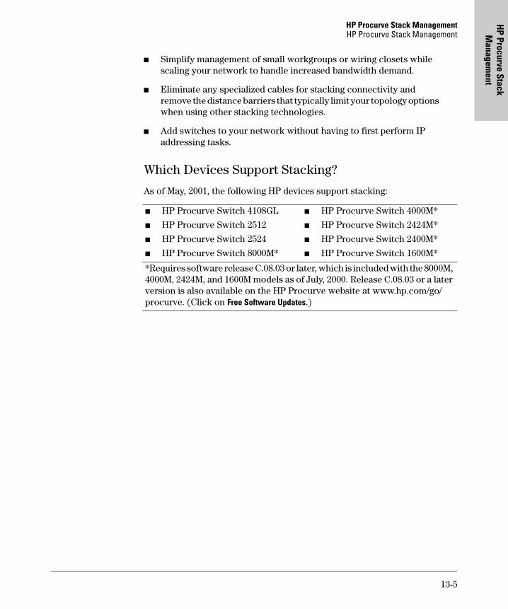
HP Procurve Stack ManagementHP Procurve Stack Management
HP Procurve Stack
Managem
ent
� Simplify management of small workgroups or wiring closets while scaling your network to handle increased bandwidth demand.
� Eliminate any specialized cables for stacking connectivity and remove the distance barriers that typically limit your topology options when using other stacking technologies.
� Add switches to your network without having to first perform IP addressing tasks.
Which Devices Support Stacking?
As of May, 2001, the following HP devices support stacking:
� HP Procurve Switch 4108GL
� HP Procurve Switch 2512
� HP Procurve Switch 2524
� HP Procurve Switch 8000M*
� HP Procurve Switch 4000M*
� HP Procurve Switch 2424M*
� HP Procurve Switch 2400M*
� HP Procurve Switch 1600M*
*Requires software release C.08.03 or later, which is included with the 8000M, 4000M, 2424M, and 1600M models as of July, 2000. Release C.08.03 or a later version is also available on the HP Procurve website at www.hp.com/go/procurve. (Click on Free Software Updates.)
13-5
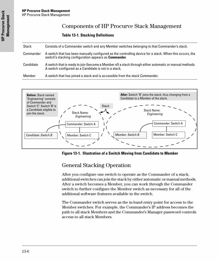
HP Procurve Stack Management HP Procurve Stack Management
HP
Proc
urve
Sta
ck
Man
agem
ent
Components of HP Procurve Stack Management
Table 13-1. Stacking Definitions
Figure 13-1. Illustration of a Switch Moving from Candidate to Member
General Stacking Operation
After you configure one switch to operate as the Commander of a stack, additional switches can join the stack by either automatic or manual methods. After a switch becomes a Member, you can work through the Commander switch to further configure the Member switch as necessary for all of the additional software features available in the switch.
The Commander switch serves as the in-band entry point for access to the Member switches. For example, the Commander’s IP address becomes the path to all stack Members and the Commander’s Manager password controls access to all stack Members.
Stack Consists of a Commander switch and any Member switches belonging to that Commander’s stack.
Commander A switch that has been manually configured as the controlling device for a stack. When this occurs, the switch’s stacking configuration appears as Commander.
Candidate A switch that is ready to join (become a Member of) a stack through either automatic or manual methods. A switch configured as a Candidate is not in a stack.
Member A switch that has joined a stack and is accessible from the stack Commander.
Commander: Switch A
Member: Switch CCandidate: Switch B
Before: Stack named "Engineering" consists of Commander and Switch "C". Switch "B" is a Candidate eligible to join the stack.
Commander: Switch A
Member: Switch CMember: Switch B
After: Switch "B" joins the stack, thus changing from a Candidate to a Member of the stack.
Stack
Stack Name: Engineering
Stack Name: Engineering
13-6
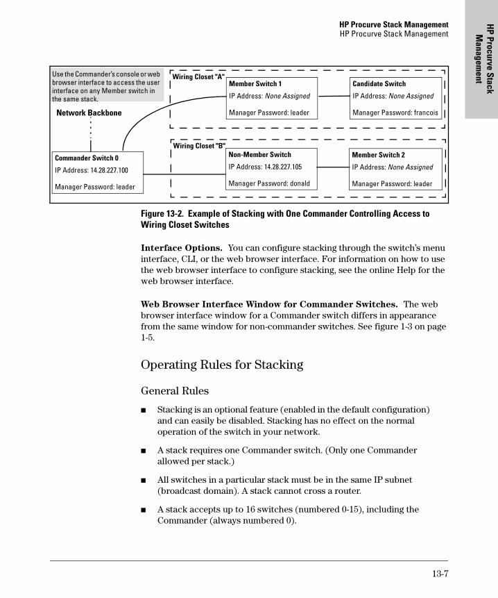
HP Procurve Stack ManagementHP Procurve Stack Management
HP Procurve Stack
Managem
ent
Figure 13-2. Example of Stacking with One Commander Controlling Access to Wiring Closet Switches
Interface Options. You can configure stacking through the switch’s menu interface, CLI, or the web browser interface. For information on how to use the web browser interface to configure stacking, see the online Help for the web browser interface.
Web Browser Interface Window for Commander Switches. The web browser interface window for a Commander switch differs in appearance from the same window for non-commander switches. See figure 1-3 on page 1-5.
Operating Rules for Stacking
General Rules
� Stacking is an optional feature (enabled in the default configuration) and can easily be disabled. Stacking has no effect on the normal operation of the switch in your network.
� A stack requires one Commander switch. (Only one Commander allowed per stack.)
� All switches in a particular stack must be in the same IP subnet (broadcast domain). A stack cannot cross a router.
� A stack accepts up to 16 switches (numbered 0-15), including the Commander (always numbered 0).
Member Switch 1
IP Address: None Assigned
Manager Password: leader
Candidate Switch
IP Address: None Assigned
Manager Password: francois
Non-Member Switch
IP Address: 14.28.227.105
Manager Password: donald
Member Switch 2
IP Address: None Assigned
Manager Password: leader
Wiring Closet "B"
Wiring Closet "A"
Commander Switch 0
IP Address: 14.28.227.100
Manager Password: leader
Use the Commander’s console or web browser interface to access the user interface on any Member switch in the same stack.
Network Backbone
13-7
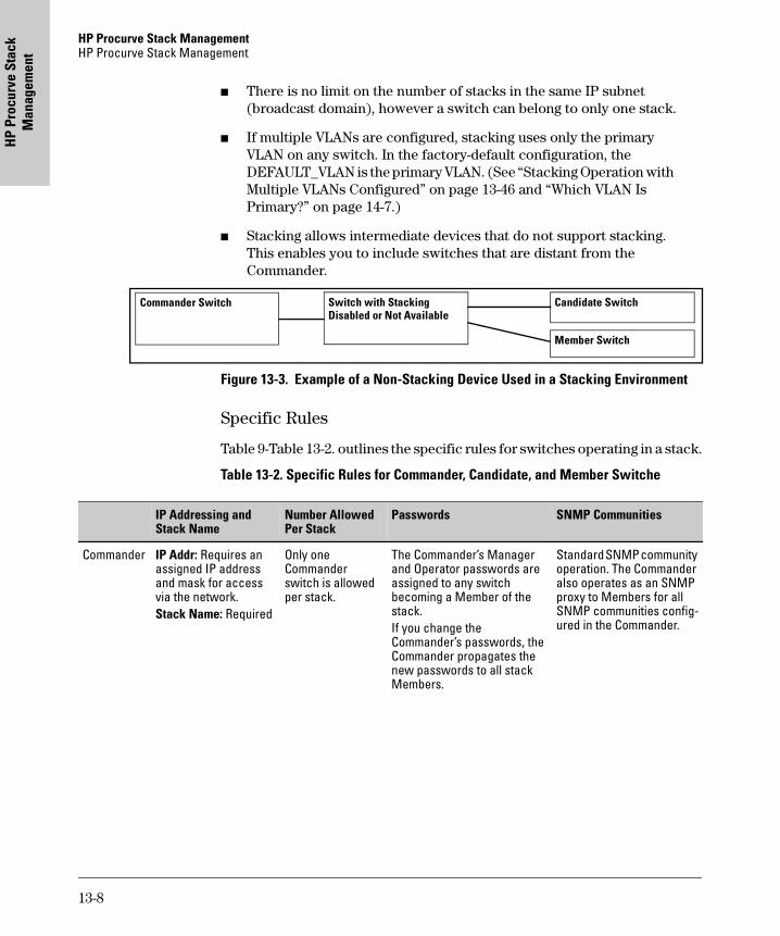
HP Procurve Stack Management HP Procurve Stack Management
HP
Proc
urve
Sta
ck
Man
agem
ent
� There is no limit on the number of stacks in the same IP subnet (broadcast domain), however a switch can belong to only one stack.
� If multiple VLANs are configured, stacking uses only the primary VLAN on any switch. In the factory-default configuration, the DEFAULT_VLAN is the primary VLAN. (See “Stacking Operation with Multiple VLANs Configured” on page 13-46 and “Which VLAN Is Primary?” on page 14-7.)
� Stacking allows intermediate devices that do not support stacking. This enables you to include switches that are distant from the Commander.
Figure 13-3. Example of a Non-Stacking Device Used in a Stacking Environment
Specific Rules
Table 9-Table 13-2. outlines the specific rules for switches operating in a stack.
Table 13-2. Specific Rules for Commander, Candidate, and Member Switche
Commander Switch Switch with Stacking Disabled or Not Available
Member Switch
Candidate Switch
IP Addressing and Stack Name
Number Allowed Per Stack
Passwords SNMP Communities
Commander IP Addr: Requires an assigned IP address and mask for access via the network. Stack Name: Required
Only one Commander switch is allowed per stack.
The Commander’s Manager and Operator passwords are assigned to any switch becoming a Member of the stack. If you change the Commander’s passwords, the Commander propagates the new passwords to all stack Members.
Standard SNMP community operation. The Commander also operates as an SNMP proxy to Members for all SNMP communities config-ured in the Commander.
13-8
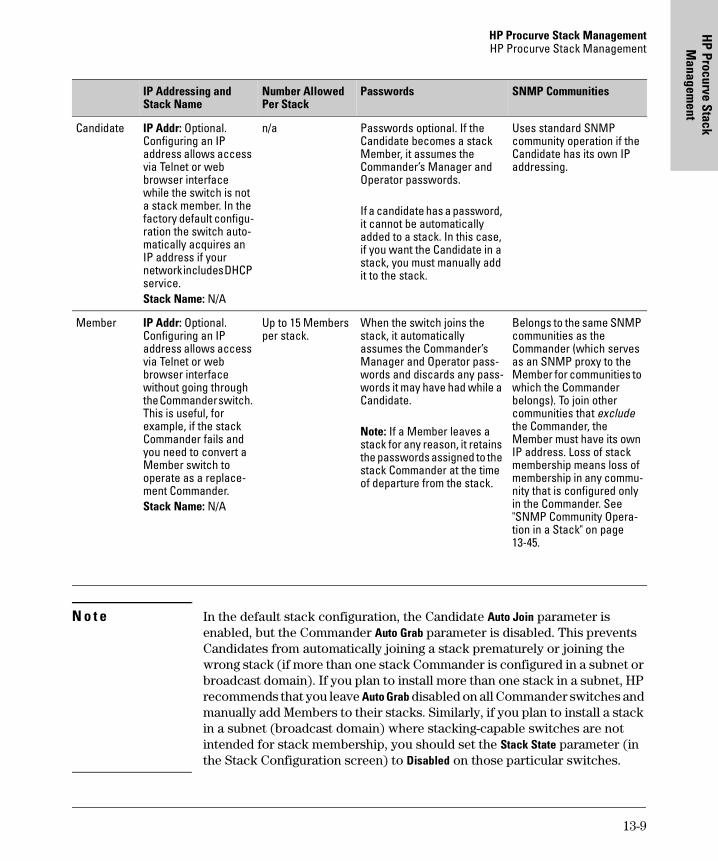
HP Procurve Stack ManagementHP Procurve Stack Management
HP Procurve Stack
Managem
ent
N o t e In the default stack configuration, the Candidate Auto Join parameter is enabled, but the Commander Auto Grab parameter is disabled. This prevents Candidates from automatically joining a stack prematurely or joining the wrong stack (if more than one stack Commander is configured in a subnet or broadcast domain). If you plan to install more than one stack in a subnet, HP recommends that you leave Auto Grab disabled on all Commander switches and manually add Members to their stacks. Similarly, if you plan to install a stack in a subnet (broadcast domain) where stacking-capable switches are not intended for stack membership, you should set the Stack State parameter (in the Stack Configuration screen) to Disabled on those particular switches.
Candidate IP Addr: Optional. Configuring an IP address allows access via Telnet or web browser interface while the switch is not a stack member. In the factory default configu-ration the switch auto-matically acquires an IP address if your network includes DHCP service.Stack Name: N/A
n/a Passwords optional. If the Candidate becomes a stack Member, it assumes the Commander’s Manager and Operator passwords.
If a candidate has a password, it cannot be automatically added to a stack. In this case, if you want the Candidate in a stack, you must manually add it to the stack.
Uses standard SNMP community operation if the Candidate has its own IP addressing.
Member IP Addr: Optional. Configuring an IP address allows access via Telnet or web browser interface without going through the Commander switch. This is useful, for example, if the stack Commander fails and you need to convert a Member switch to operate as a replace-ment Commander.Stack Name: N/A
Up to 15 Members per stack.
When the switch joins the stack, it automatically assumes the Commander’s Manager and Operator pass-words and discards any pass-words it may have had while a Candidate.
Note: If a Member leaves a stack for any reason, it retains the passwords assigned to the stack Commander at the time of departure from the stack.
Belongs to the same SNMP communities as the Commander (which serves as an SNMP proxy to the Member for communities to which the Commander belongs). To join other communities that exclude the Commander, the Member must have its own IP address. Loss of stack membership means loss of membership in any commu-nity that is configured only in the Commander. See "SNMP Community Opera-tion in a Stack" on page 13-45.
IP Addressing and Stack Name
Number Allowed Per Stack
Passwords SNMP Communities
13-9
HP Procurve Stack Management HP Procurve Stack Management
HP
Proc
urve
Sta
ck
Man
agem
ent
Overview of Configuring and Bringing Up a Stack
This process assumes that:
� All switches you want to include in a stack are connected to the same subnet (broadcast domain).
� If VLANs are enabled on the switches you want to include in the stack, then the ports linking the stacked switches must be on the primary VLAN in each switch (which, in the default configuration, is the default VLAN). If the primary VLAN is tagged, then each switch in the stack must use the same VLAN ID (VID) for the primary VLAN. (See “Which VLAN Is Primary?” on page 14-7, and “Stacking Operation with Multiple VLANs Configured” on page 13-46.)
� If you are including an HP Procurve Switch 8000M, 4000M, 2424M, 2400M, or 1600M in a stack, you must first update all such devices to software version C.08.xx or later. (You can get a copy of the software from HP’s Procurve website and/or copy it from one switch to another. For downloading instructions, see appendix A, "File Transfers", in the Management and Configuration Guide you received with these switch models.)
Options for Configuring a Commander and Candidates. Depending on how Commander and Candidate switches are configured, Candidates can join a stack either automatically or by a Commander manually adding (“pulling”) them into the stack. In the default configuration, a Candidate joins only when manually pulled by a Commander. You can reconfigure a Commander to automatically pull in Candidates that are in the default stacking configura-tion. You can also reconfigure a Candidate switch to either “push” itself into a particular Commander’s stack, convert the Candidate to a Commander (for a stack that does not already have a Commander), or to operate as a standa-lone switch without stacking. The following table shows your control options for adding Members to a stack.
13-10
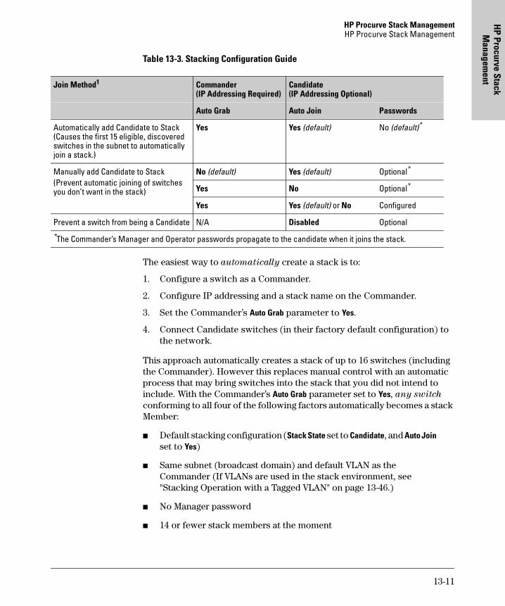
HP Procurve Stack ManagementHP Procurve Stack Management
HP Procurve Stack
Managem
ent
Table 13-3. Stacking Configuration Guide
The easiest way to automatically create a stack is to:
1. Configure a switch as a Commander.
2. Configure IP addressing and a stack name on the Commander.
3. Set the Commander’s Auto Grab parameter to Yes.
4. Connect Candidate switches (in their factory default configuration) to the network.
This approach automatically creates a stack of up to 16 switches (including the Commander). However this replaces manual control with an automatic process that may bring switches into the stack that you did not intend to include. With the Commander’s Auto Grab parameter set to Yes, any switch conforming to all four of the following factors automatically becomes a stack Member:
� Default stacking configuration (Stack State set to Candidate, and Auto Join set to Yes)
� Same subnet (broadcast domain) and default VLAN as the Commander (If VLANs are used in the stack environment, see "Stacking Operation with a Tagged VLAN" on page 13-46.)
� No Manager password
� 14 or fewer stack members at the moment
Join Method1 Commander (IP Addressing Required)
Candidate (IP Addressing Optional)
Auto Grab Auto Join Passwords
Automatically add Candidate to Stack (Causes the first 15 eligible, discovered switches in the subnet to automatically join a stack.)
Yes Yes (default) No (default)*
Manually add Candidate to Stack(Prevent automatic joining of switches you don’t want in the stack)
No (default) Yes (default) Optional*
Yes No Optional*
Yes Yes (default) or No Configured
Prevent a switch from being a Candidate N/A Disabled Optional
*The Commander’s Manager and Operator passwords propagate to the candidate when it joins the stack.
13-11
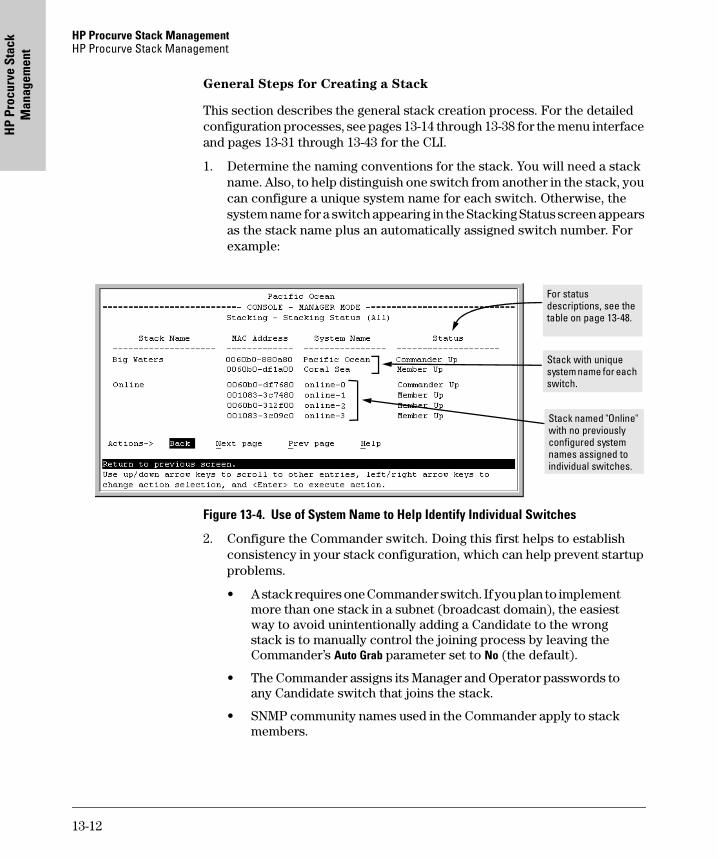
HP Procurve Stack Management HP Procurve Stack Management
HP
Proc
urve
Sta
ck
Man
agem
ent
General Steps for Creating a Stack
This section describes the general stack creation process. For the detailed configuration processes, see pages 13-14 through 13-38 for the menu interface and pages 13-31 through 13-43 for the CLI.
1. Determine the naming conventions for the stack. You will need a stack name. Also, to help distinguish one switch from another in the stack, you can configure a unique system name for each switch. Otherwise, the system name for a switch appearing in the Stacking Status screen appears as the stack name plus an automatically assigned switch number. For example:
Figure 13-4. Use of System Name to Help Identify Individual Switches
2. Configure the Commander switch. Doing this first helps to establish consistency in your stack configuration, which can help prevent startup problems.
• A stack requires one Commander switch. If you plan to implement more than one stack in a subnet (broadcast domain), the easiest way to avoid unintentionally adding a Candidate to the wrong stack is to manually control the joining process by leaving the Commander’s Auto Grab parameter set to No (the default).
• The Commander assigns its Manager and Operator passwords to any Candidate switch that joins the stack.
• SNMP community names used in the Commander apply to stack members.
Stack with unique system name for each switch.
Stack named "Online" with no previously configured system names assigned to individual switches.
For status descriptions, see the table on page 13-48.
13-12
HP Procurve Stack ManagementHP Procurve Stack Management
HP Procurve Stack
Managem
ent
3. For automatically or manually pulling Candidate switches into a stack, you can leave such switches in their default stacking configuration. If you need to access Candidate switches through your network before they join the stack, assign IP addresses to these devices. Otherwise, IP addressing is optional for Candidates and Members. (Note that once a Candidate becomes a member, you can access it through the Commander to assign IP addressing or make other configuration changes.)
4. Make a record of any Manager passwords assigned to the switches (intended for your stack) that are not currently members. (You will have to use these passwords to enable the protected switches to join the stack.)
5. If you are using VLANs in the stacking environment, you must use the default VLAN for stacking links. For more information, see "Stacking Operation with a Tagged VLAN" on page 13-46.
6. Ensure that all switches intended for the stack are connected to the same subnet (broadcast domain). As soon as you connect the Commander, it will begin discovering the available Candidates in the subnet.
• If you configured the Commander to automatically add Members (Auto Grab set to Yes), then the first 15 discovered Candidates meeting both of the following criteria will automatically become stack Members:
– Auto Join parameter set to Yes (the default)
– Manager password not configured
• If you configured the Commander to manually add Members (Auto Grab set to No—the default), you can begin the process of selecting and adding the desired Candidates.
7. Ensure that all switches intended for the stack have joined.
8. If you need to perform specific configuration or monitoring tasks on a Member, use the console interface on the Commander to select and access the Member.
13-13
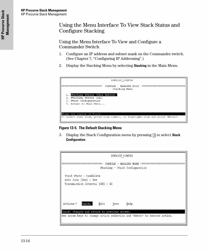
HP Procurve Stack Management HP Procurve Stack Management
HP
Proc
urve
Sta
ck
Man
agem
ent
Using the Menu Interface To View Stack Status and Configure Stacking
Using the Menu Interface To View and Configure a Commander Switch
1. Configure an IP address and subnet mask on the Commander switch. (See Chapter 7, “Configuring IP Addressing”.)
2. Display the Stacking Menu by selecting Stacking in the Main Menu.
Figure 13-5. The Default Stacking Menu
3. Display the Stack Configuration menu by pressing [3] to select Stack Configuration.
13-14
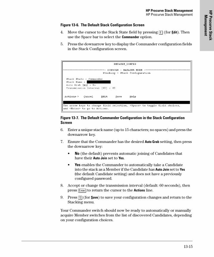
HP Procurve Stack ManagementHP Procurve Stack Management
HP Procurve Stack
Managem
ent
Figure 13-6. The Default Stack Configuration Screen
4. Move the cursor to the Stack State field by pressing [E] (for Edit). Then use the Space bar to select the Commander option.
5. Press the downarrow key to display the Commander configuration fields in the Stack Configuration screen.
Figure 13-7. The Default Commander Configuration in the Stack Configuration Screen
6. Enter a unique stack name (up to 15 characters; no spaces) and press the downarrow key.
7. Ensure that the Commander has the desired Auto Grab setting, then press the downarrow key:
• No (the default) prevents automatic joining of Candidates that have their Auto Join set to Yes.
• Yes enables the Commander to automatically take a Candidate into the stack as a Member if the Candidate has Auto Join set to Yes (the default Candidate setting) and does not have a previously configured password.
8. Accept or change the transmission interval (default: 60 seconds), then press [Enter] to return the cursor to the Actions line.
9. Press [S] (for Save) to save your configuration changes and return to the Stacking menu.
Your Commander switch should now be ready to automatically or manually acquire Member switches from the list of discovered Candidates, depending on your configuration choices.
13-15
HP Procurve Stack Management HP Procurve Stack Management
HP
Proc
urve
Sta
ck
Man
agem
ent
Using the Menu To Manage a Candidate Switch
Using the menu interface, you can perform these actions on a Candidate switch:
� Add (“push”) the Candidate into an existing stack
� Modify the Candidate’s stacking configuration (Auto Join and Transmission Interval)
� Convert the Candidate to a Commander
� Disable stacking on the Candidate so that it operates as a standalone switch
In its default stacking configuration, a Candidate switch can either automati-cally join a stack or be manually added ("pulled") into a stack by a Commander, depending on the Commander’s Auto Grab setting. The following table lists the Candidate’s configuration options:
13-16
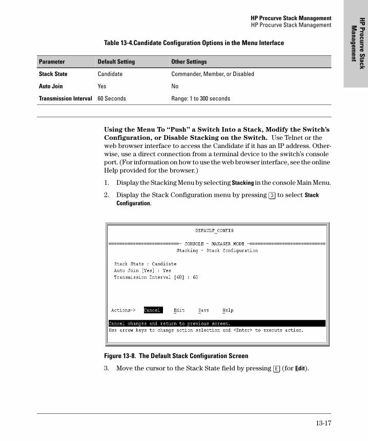
HP Procurve Stack ManagementHP Procurve Stack Management
HP Procurve Stack
Managem
ent
Table 13-4.Candidate Configuration Options in the Menu Interface
Using the Menu To “Push” a Switch Into a Stack, Modify the Switch’s
Configuration, or Disable Stacking on the Switch. Use Telnet or the web browser interface to access the Candidate if it has an IP address. Other-wise, use a direct connection from a terminal device to the switch’s console port. (For information on how to use the web browser interface, see the online Help provided for the browser.)
1. Display the Stacking Menu by selecting Stacking in the console Main Menu.
2. Display the Stack Configuration menu by pressing [3] to select Stack Configuration.
Figure 13-8. The Default Stack Configuration Screen
3. Move the cursor to the Stack State field by pressing [E] (for Edit).
Parameter Default Setting Other Settings
Stack State Candidate Commander, Member, or Disabled
Auto Join Yes No
Transmission Interval 60 Seconds Range: 1 to 300 seconds
13-17
HP Procurve Stack Management HP Procurve Stack Management
HP
Proc
urve
Sta
ck
Man
agem
ent
4. Do one of the following:
• To disable stacking on the Candidate, use the Space bar to select the Disabled option, then go to step 5.
Note: Using the menu interface to disable stacking on a Candidate removes the Candidate from all stacking menus.
• To insert the Candidate into a specific Commander’s stack:
i. Use the space bar to select Member.
ii. Press [Tab] once to display the Commander MAC Address parameter, then enter the MAC address of the desired Commander.
• To change Auto Join or Transmission Interval, use [Tab] to select the desired parameter, and:
– To change Auto Join, use the Space bar.
– To change Transmission Interval, type in the new value in the range of 1 to 300 seconds.
Note: All switches in the stack must be set to the same transmis-sion interval to help ensure proper stacking operation. HP recom-mends that you leave this parameter set to the default 60 seconds.
Then go to step 5.
5. press [Enter] to return the cursor to the Actions line.
6. Press [S] (for Save) to save your configuration changes and return to the Stacking menu.
Using the Commander To Manage The Stack
The Commander normally operates as your stack manager and point of entry into other switches in the stack. This typically includes:
� Adding new stack members
� Moving members between stacks
� Removing members from a stack
� Accessing stack members for individual configuration changes and traffic monitoring
The Commander also imposes its passwords on all stack members and pro-vides SNMP community membership to the stack. (See “SNMP Community Operation in a Stack” on page 13-45.)
13-18
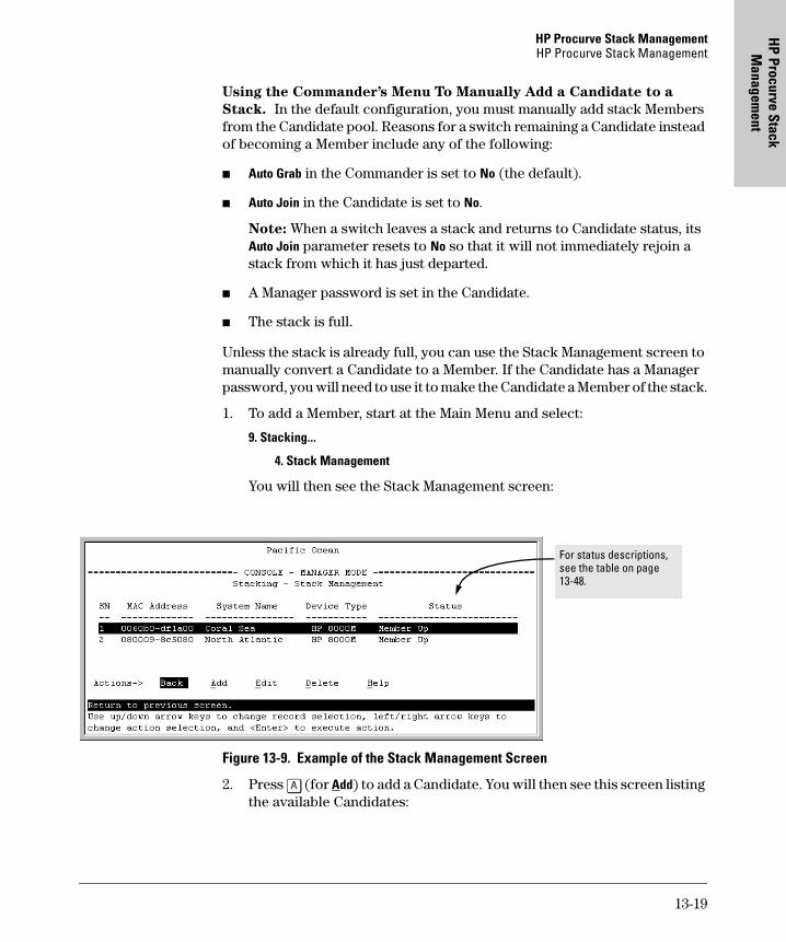
HP Procurve Stack ManagementHP Procurve Stack Management
HP Procurve Stack
Managem
ent
Using the Commander’s Menu To Manually Add a Candidate to a
Stack. In the default configuration, you must manually add stack Members from the Candidate pool. Reasons for a switch remaining a Candidate instead of becoming a Member include any of the following:
� Auto Grab in the Commander is set to No (the default).
� Auto Join in the Candidate is set to No.
Note: When a switch leaves a stack and returns to Candidate status, its Auto Join parameter resets to No so that it will not immediately rejoin a stack from which it has just departed.
� A Manager password is set in the Candidate.
� The stack is full.
Unless the stack is already full, you can use the Stack Management screen to manually convert a Candidate to a Member. If the Candidate has a Manager password, you will need to use it to make the Candidate a Member of the stack.
1. To add a Member, start at the Main Menu and select:
9. Stacking...
4. Stack Management
You will then see the Stack Management screen:
Figure 13-9. Example of the Stack Management Screen
2. Press [A] (for Add) to add a Candidate. You will then see this screen listing the available Candidates:
For status descriptions, see the table on page 13-48.
13-19
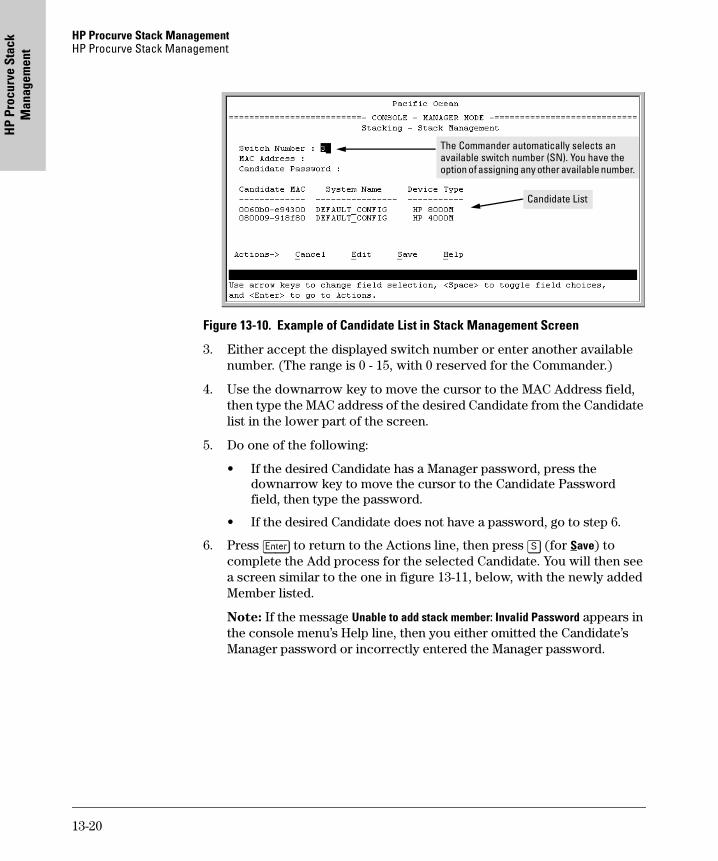
HP Procurve Stack Management HP Procurve Stack Management
HP
Proc
urve
Sta
ck
Man
agem
ent
Figure 13-10. Example of Candidate List in Stack Management Screen
3. Either accept the displayed switch number or enter another available number. (The range is 0 - 15, with 0 reserved for the Commander.)
4. Use the downarrow key to move the cursor to the MAC Address field, then type the MAC address of the desired Candidate from the Candidate list in the lower part of the screen.
5. Do one of the following:
• If the desired Candidate has a Manager password, press the downarrow key to move the cursor to the Candidate Password field, then type the password.
• If the desired Candidate does not have a password, go to step 6.
6. Press [Enter] to return to the Actions line, then press [S] (for Save) to complete the Add process for the selected Candidate. You will then see a screen similar to the one in figure 13-11, below, with the newly added Member listed.
Note: If the message Unable to add stack member: Invalid Password appears in the console menu’s Help line, then you either omitted the Candidate’s Manager password or incorrectly entered the Manager password.
The Commander automatically selects an available switch number (SN). You have the option of assigning any other available number.
Candidate List
13-20
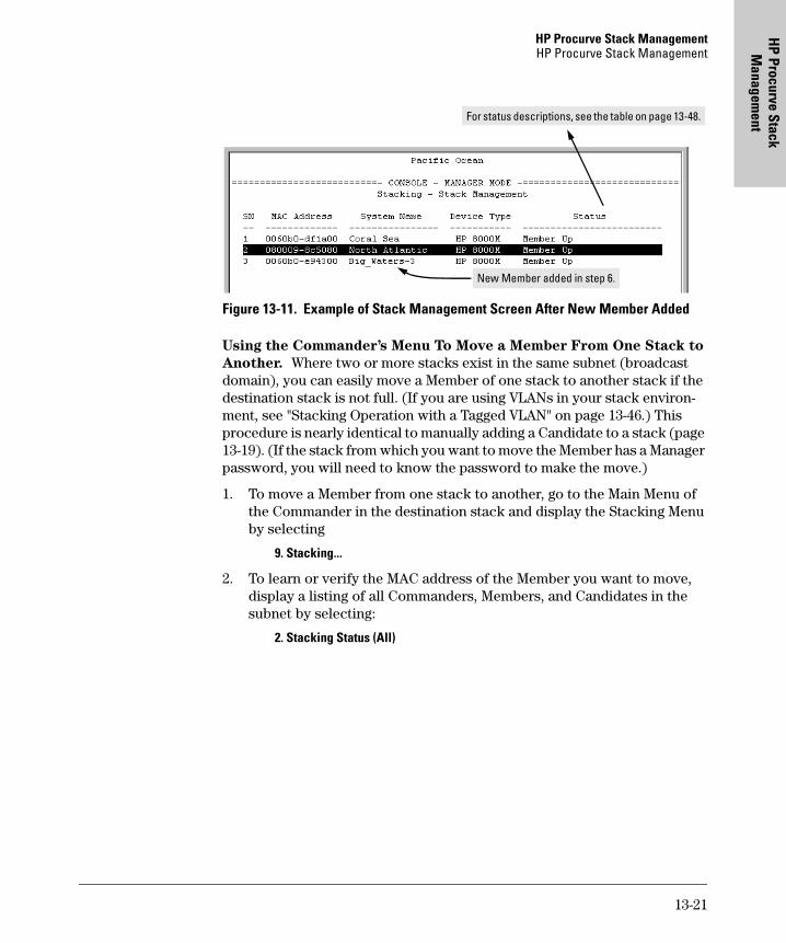
HP Procurve Stack ManagementHP Procurve Stack Management
HP Procurve Stack
Managem
ent
Figure 13-11. Example of Stack Management Screen After New Member Added
Using the Commander’s Menu To Move a Member From One Stack to
Another. Where two or more stacks exist in the same subnet (broadcast domain), you can easily move a Member of one stack to another stack if the destination stack is not full. (If you are using VLANs in your stack environ-ment, see "Stacking Operation with a Tagged VLAN" on page 13-46.) This procedure is nearly identical to manually adding a Candidate to a stack (page 13-19). (If the stack from which you want to move the Member has a Manager password, you will need to know the password to make the move.)
1. To move a Member from one stack to another, go to the Main Menu of the Commander in the destination stack and display the Stacking Menu by selecting
9. Stacking...
2. To learn or verify the MAC address of the Member you want to move, display a listing of all Commanders, Members, and Candidates in the subnet by selecting:
2. Stacking Status (All)
New Member added in step 6.
For status descriptions, see the table on page 13-48.
13-21
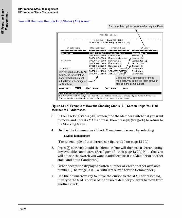
HP Procurve Stack Management HP Procurve Stack Management
HP
Proc
urve
Sta
ck
Man
agem
ent
You will then see the Stacking Status (All) screen:
Figure 13-12. Example of How the Stacking Status (All) Screen Helps You Find Member MAC Addresses
3. In the Stacking Status (All) screen, find the Member switch that you want to move and note its MAC address, then press [B] (for Back) to return to the Stacking Menu.
4. Display the Commander’s Stack Management screen by selecting
4. Stack Management
(For an example of this screen, see figure 13-9 on page 13-19.)
5. Press [A] (for Add) to add the Member. You will then see a screen listing any available candidates. (See figure 13-10 on page 13-20.) Note that you will not see the switch you want to add because it is a Member of another stack and not a Candidate.)
6. Either accept the displayed switch number or enter another available number. (The range is 0 - 15, with 0 reserved for the Commander.)
7. Use the downarrow key to move the cursor to the MAC Address field, then type the MAC address of the desired Member you want to move from another stack.
This column lists the MAC Addresses for switches discovered (in the local subnet) that are configured for Stacking.
Using the MAC addresses for these Members, you can move them between stacks in the same subnet.
For status descriptions, see the table on page 13-48.
13-22
HP Procurve Stack ManagementHP Procurve Stack Management
HP Procurve Stack
Managem
ent
8. Do one of the following:
• If the stack containing the Member you are moving has a Manager password, press the downarrow key to select the Candidate Password field, then type the password.
• If the stack containing the Member you want to move does not have a password, go to step 9.
9. Press [Enter] to return to the Actions line, then press [S] (for Save) to complete the Add process for the selected Member. You will then see a screen similar to the one in figure 13-9 on page 13-19, with the newly added Member listed.
N o t e : If the message Unable to add stack member: Invalid Password appears in the console menu’s Help line, then you either omitted the Manager password for the stack containing the Member or incorrectly entered the Manager password.
You can “push” a Member from one stack to another by going to the Member’s interface and entering the MAC address of the destination stack Commander in the Member’s Commander MAC Address field. Using this method moves the Member to another stack without a need for knowing the Manager password in that stack, but also blocks access to the Member from the original Commander.
Using the Commander’s Menu To Remove a Stack Member. These rules affect removals from a stack:
� When a Candidate becomes a Member, its Auto Join parameter is automatically set to No. This prevents the switch from automatically rejoining a stack as soon as you remove it from the stack.
� When you use the Commander to remove a switch from a stack, the switch rejoins the Candidate pool for your IP subnet (broadcast domain), with Auto Join set to No.
� When you remove a Member from a stack, it frees the previously assigned switch number (SN), which then becomes available for assignment to another switch that you may subsequently add to the stack. The default switch number used for an add is the lowest unassigned number in the Member range (1 - 15; 0 is reserved for the Commander).
To remove a Member from a stack, use the Stack Management screen.
1. From the Main Menu, select:
9. Stacking...
13-23
HP Procurve Stack Management HP Procurve Stack Management
HP
Proc
urve
Sta
ck
Man
agem
ent
4. Stack Management
You will then see the Stack Management screen:
Figure 13-13. Example of Stack Management Screen with Stack Members Listed
2. Use the downarrow key to select the Member you want to remove from the stack.
Figure 13-14. Example of Selecting a Member for Removal from the Stack
3. Type [D] (for Delete) to remove the selected Member from the stack. You will then see the following prompt:
Figure 13-15. The Prompt for Completing the Deletion of a Member from the Stack
4. To continue deleting the selected Member, press the Space bar once to select Yes for the prompt, then press [Enter] to complete the deletion. The Stack Management screen updates to show the new stack Member list.
Stack Member List
For status descriptions, see the table on page 13-48.
13-24
HP Procurve Stack ManagementHP Procurve Stack Management
HP Procurve Stack
Managem
ent
Using the Commander To Access Member Switches for Configuration Changes and Monitoring Traffic
After a Candidate becomes a stack Member, you can use that stack’s Commander to access the Member’s console interface for the same configu-ration and monitoring that you would do through a Telnet or direct-connect access.
1. From the Main Menu, select:
9. Stacking...5. Stack Access
You will then see the Stack Access screen:
Figure 13-16. Example of the Stack Access Screen
Use the downarrow key to select the stack Member you want to access, then press [X] (for eXecute) to display the console interface for the selected Member. For example, if you selected switch number 1 (system name: Coral Sea) in figure 13-16 and then pressed [X], you would see the Main Menu for the switch named Coral Sea.
For status descriptions, see the table on page 13-48.
13-25
HP Procurve Stack Management HP Procurve Stack Management
HP
Proc
urve
Sta
ck
Man
agem
ent
Figure 13-17. The eXecute Command Displays the Console Main Menu for the Selected Stack Member
2. You can now make configuration changes and/or view status data for the selected Member in the same way that you would if you were directly connected or telnetted into the switch.
3. When you are finished accessing the selected Member, do the following to return to the Commander’s Stack Access screen:
a. Return to the Member’s Main Menu.
b. Press [0] (for Logout), then [Y] (for Yes).
c. Press [Return].
You should now see the Commander’s Stack Access screen. (For an example, see figure 13-16 on page 13-25.)
Converting a Commander or Member to a Member of Another Stack
When moving a commander, the following procedure returns the stack mem-bers to Candidate status (with Auto-Join set to “No”) and converts the stack Commander to a Member of another stack. When moving a member, the procedure simply pulls a Member out of one stack and pushes it into another.
1. From the Main Menu of the switch you want to move, select
9. Stacking
2. To determine the MAC address of the destination Commander, select
2. Stacking Status (All)
Main Menu for stack Member named "Coral Sea" (SN = 1 from figure 13-16)
13-26
HP Procurve Stack ManagementHP Procurve Stack Management
HP Procurve Stack
Managem
ent
3. Press [B] (for Back) to return to the Stacking Menu.
4. To display Stack Configuration menu for the switch you are moving, select
3. Stack Configuration
5. Press [E] (for Edit) to select the Stack State parameter.
6. Use the Space bar to select Member, then press [v] to move to the Com-mander MAC Address field.
7. Enter the MAC address of the destination Commander and press [Enter].
8. Press [S] (for Save).
Monitoring Stack Status
Using the stacking options in the menu interface for any switch in a stack, you can view stacking data for that switch or for all stacks in the subnet (broadcast domain). (If you are using VLANs in your stack environment, see "Stacking Operation with a Tagged VLAN" on page 13-46.) This can help you in such ways as determining the stacking configuration for individual switches, identifying stack Members and Candidates, and determining the status of individual switches in a stack. See table 13-5 on page 13-27.
Table 13-5. Stack Status Environments
Screen Name Commander Member Candidate
Stack Status (This Switch) • Commander’s stacking configuration
• Data on stack Members:– Switch Number– MAC Address– System Name– Device Type– Status
• Member’s stacking configuration• Member Status• Data identifying Member’s
Commander:– Commander Status– Commander IP Address– Commander MAC Address
Candidate’s stacking configuration
Stack Status (All) Lists devices by stack name or Candidate status (if device is not a stack Member). Includes:• Stack Name• MAC Address• System Name• Status
Same as for Commander. Same as for Commander.
13-27
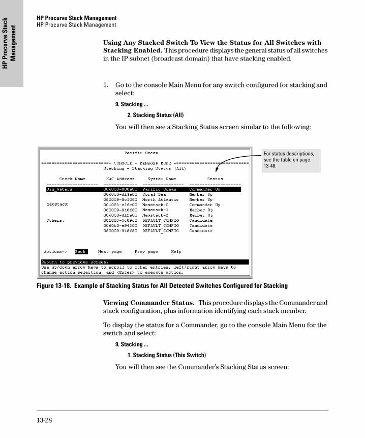
HP Procurve Stack Management HP Procurve Stack Management
HP
Proc
urve
Sta
ck
Man
agem
ent
Using Any Stacked Switch To View the Status for All Switches with
Stacking Enabled. This procedure displays the general status of all switches in the IP subnet (broadcast domain) that have stacking enabled.
1. Go to the console Main Menu for any switch configured for stacking and select:
9. Stacking ...
2. Stacking Status (All)
You will then see a Stacking Status screen similar to the following:
Figure 13-18. Example of Stacking Status for All Detected Switches Configured for Stacking
Viewing Commander Status. This procedure displays the Commander and stack configuration, plus information identifying each stack member.
To display the status for a Commander, go to the console Main Menu for the switch and select:
9. Stacking ...
1. Stacking Status (This Switch)
You will then see the Commander’s Stacking Status screen:
For status descriptions, see the table on page 13-48.
13-28
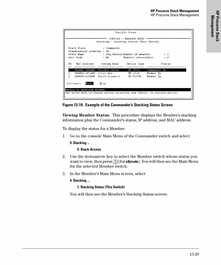
HP Procurve Stack ManagementHP Procurve Stack Management
HP Procurve Stack
Managem
ent
Figure 13-19. Example of the Commander’s Stacking Status Screen
Viewing Member Status. This procedure displays the Member’s stacking information plus the Commander’s status, IP address, and MAC address.
To display the status for a Member:
1. Go to the console Main Menu of the Commander switch and select
9. Stacking ...
5. Stack Access
2. Use the downarrow key to select the Member switch whose status you want to view, then press [X] (for eXecute). You will then see the Main Menu for the selected Member switch.
3. In the Member’s Main Menu screen, select
9. Stacking ...
1. Stacking Status (This Switch)
You will then see the Member’s Stacking Status screen:
13-29
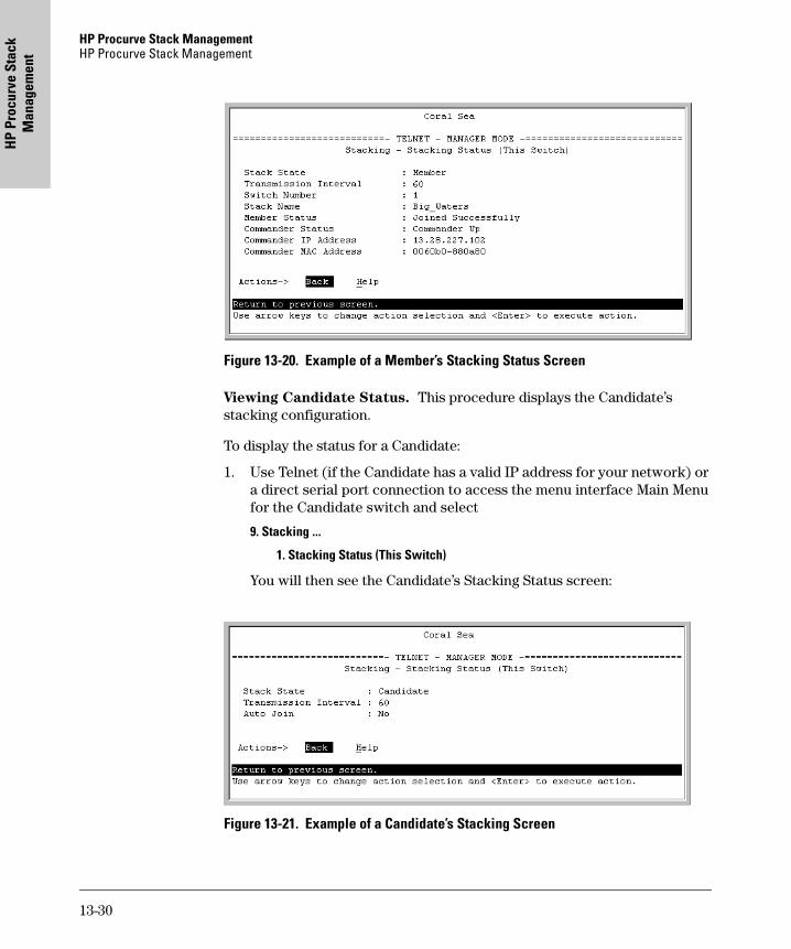
HP Procurve Stack Management HP Procurve Stack Management
HP
Proc
urve
Sta
ck
Man
agem
ent
Figure 13-20. Example of a Member’s Stacking Status Screen
Viewing Candidate Status. This procedure displays the Candidate’s stacking configuration.
To display the status for a Candidate:
1. Use Telnet (if the Candidate has a valid IP address for your network) or a direct serial port connection to access the menu interface Main Menu for the Candidate switch and select
9. Stacking ...
1. Stacking Status (This Switch)
You will then see the Candidate’s Stacking Status screen:
Figure 13-21. Example of a Candidate’s Stacking Screen
13-30
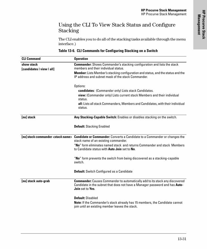
HP Procurve Stack ManagementHP Procurve Stack Management
HP Procurve Stack
Managem
ent
Using the CLI To View Stack Status and Configure Stacking
The CLI enables you to do all of the stacking tasks available through the menu interface.)
Table 13-6. CLI Commands for Configuring Stacking on a Switch
CLI Command Operation
show stack[candidates | view | all]
Commander: Shows Commander’s stacking configuration and lists the stack members and their individual status.Member: Lists Member’s stacking configuration and status, and the status and the IP address and subnet mask of the stack Commander.
Options:candidates: (Commander only) Lists stack Candidates.view: (Commander only) Lists current stack Members and their individual status.all: Lists all stack Commanders, Members and Candidates, with their individual status.
[no] stack Any Stacking-Capable Switch: Enables or disables stacking on the switch.
Default: Stacking Enabled
[no] stack commander <stack name> Candidate or Commander: Converts a Candidate to a Commander or changes the stack name of an existing commander. “No” form eliminates named stack and returns Commander and stack Members to Candidate status with Auto Join set to No.
“No” form prevents the switch from being discovered as a stacking-capable switch.
Default: Switch Configured as a Candidate
[no] stack auto-grab Commander: Causes Commander to automatically add to its stack any discovered Candidate in the subnet that does not have a Manager password and has Auto-Join set to Yes.
Default: DisabledNote: If the Commander’s stack already has 15 members, the Candidate cannot join until an existing member leaves the stack.
13-31
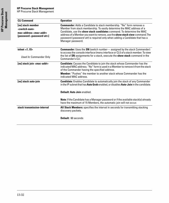
HP Procurve Stack Management HP Procurve Stack Management
HP
Proc
urve
Sta
ck
Man
agem
ent
[no] stack member <switch-num> mac-address <mac-addr> [password <password-str>]
Commander: Adds a Candidate to stack membership. “No” form removes a Member from stack membership. To easily determine the MAC address of a Candidate, use the show stack candidates command. To determine the MAC address of a Member you want to remove, use the show stack view command.The password (password-str) is required only when adding a Candidate that has a Manager password.
telnet <1..15>
Used In: Commander Only
Commander: Uses the SN (switch number— assigned by the stack Commander) to access the console interface (menu interface or CLI) of a stack member. To view the list of SN assignments for a stack, execute the show stack command in the Commander’s CLI.
[no] stack join <mac-addr> Candidate: Causes the Candidate to join the stack whose Commander has the indicated MAC address. “No” form is used in a Member to remove it from the stack of the Commander having the specified address.Member: “Pushes” the member to another stack whose Commander has the indicated MAC address.
[no] stack auto-join Candidate: Enables Candidate to automatically join the stack of any Commander in the IP subnet that has Auto Grab enabled, or disables Auto-Join in the candidate.
Default: Auto Join enabled.
Note: If the Candidate has a Manager password or if the available stack(s) already have the maximum of 15 Members, the automatic join will not occur.
stack transmission-interval All Stack Members: specifies the interval in seconds for transmitting stacking discovery packets.
Default: 60 seconds
CLI Command Operation
13-32
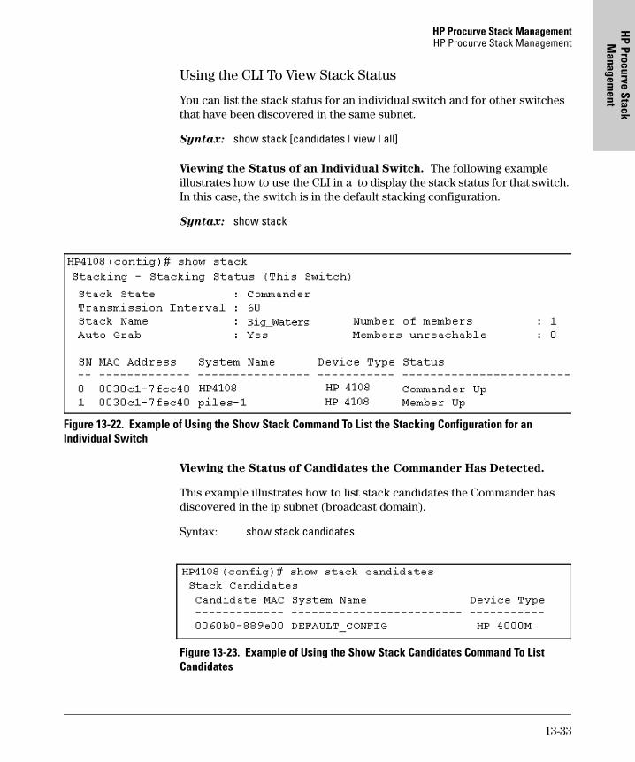
HP Procurve Stack ManagementHP Procurve Stack Management
HP Procurve Stack
Managem
ent
Using the CLI To View Stack Status
You can list the stack status for an individual switch and for other switches that have been discovered in the same subnet.
Syntax: show stack [candidates | view | all]
Viewing the Status of an Individual Switch. The following example illustrates how to use the CLI in a to display the stack status for that switch. In this case, the switch is in the default stacking configuration.
Syntax: show stack
Figure 13-22. Example of Using the Show Stack Command To List the Stacking Configuration for an Individual Switch
Viewing the Status of Candidates the Commander Has Detected.
This example illustrates how to list stack candidates the Commander has discovered in the ip subnet (broadcast domain).
Syntax: show stack candidates
Figure 13-23. Example of Using the Show Stack Candidates Command To List Candidates
13-33
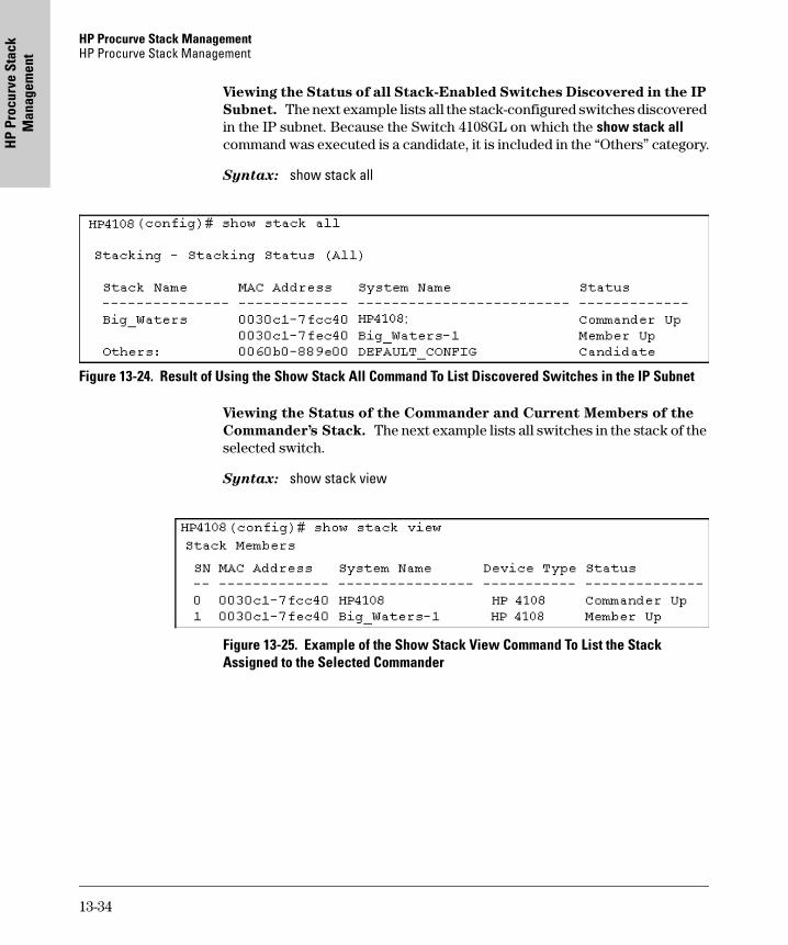
HP Procurve Stack Management HP Procurve Stack Management
HP
Proc
urve
Sta
ck
Man
agem
ent
Viewing the Status of all Stack-Enabled Switches Discovered in the IP
Subnet. The next example lists all the stack-configured switches discovered in the IP subnet. Because the Switch 4108GL on which the show stack all command was executed is a candidate, it is included in the “Others” category.
Syntax: show stack all
Figure 13-24. Result of Using the Show Stack All Command To List Discovered Switches in the IP Subnet
Viewing the Status of the Commander and Current Members of the
Commander’s Stack. The next example lists all switches in the stack of the selected switch.
Syntax: show stack view
Figure 13-25. Example of the Show Stack View Command To List the Stack Assigned to the Selected Commander
13-34
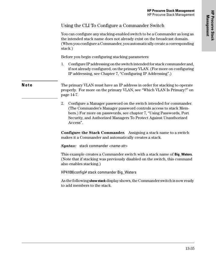
HP Procurve Stack ManagementHP Procurve Stack Management
HP Procurve Stack
Managem
ent
Using the CLI To Configure a Commander Switch
You can configure any stacking-enabled switch to be a Commander as long as the intended stack name does not already exist on the broadcast domain. (When you configure a Commander, you automatically create a corresponding stack.)
Before you begin configuring stacking parameters:
1. Configure IP addressing on the switch intended for stack commander and, if not already configured, on the primary VLAN. (For more on configuring IP addressing, see Chapter 7, “Configuring IP Addressing”.)
N o t e The primary VLAN must have an IP address in order for stacking to operate properly. For more on the primary VLAN, see “Which VLAN Is Primary?” on page 14-7.
2. Configure a Manager password on the switch intended for commander. (The Commander’s Manager password controls access to stack Mem-bers.) For more on passwords, see chapter 7, “Using Passwords, Port Security, and Authorized Managers To Protect Against Unauthorized Access”.
Configure the Stack Commander. Assigning a stack name to a switch makes it a Commander and automatically creates a stack.
Syntax: stack commander <name-str>
This example creates a Commander switch with a stack name of Big_Waters. (Note that if stacking was previously disabled on the switch, this command also enables stacking.)
HP4108(config)# stack commander Big_Waters
As the following show stack display shows, the Commander switch is now ready to add members to the stack.
13-35
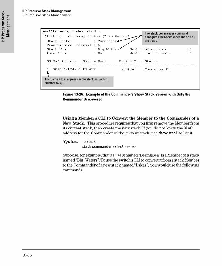
HP Procurve Stack Management HP Procurve Stack Management
HP
Proc
urve
Sta
ck
Man
agem
ent
Figure 13-26. Example of the Commander’s Show Stack Screen with Only the Commander Discovered
Using a Member’s CLI to Convert the Member to the Commander of a
New Stack. This procedure requires that you first remove the Member from its current stack, then create the new stack. If you do not know the MAC address for the Commander of the current stack, use show stack to list it.
Syntax: no stack stack commander <stack name>
Suppose, for example, that a HP4108 named “Bering Sea” is a Member of a stack named “Big_Waters”. To use the switch’s CLI to convert it from a stack Member to the Commander of a new stack named “Lakes”, you would use the following commands:
The stack commander command configures the Commander and names the stack.
The Commander appears in the stack as Switch Number (SN) 0.
13-36
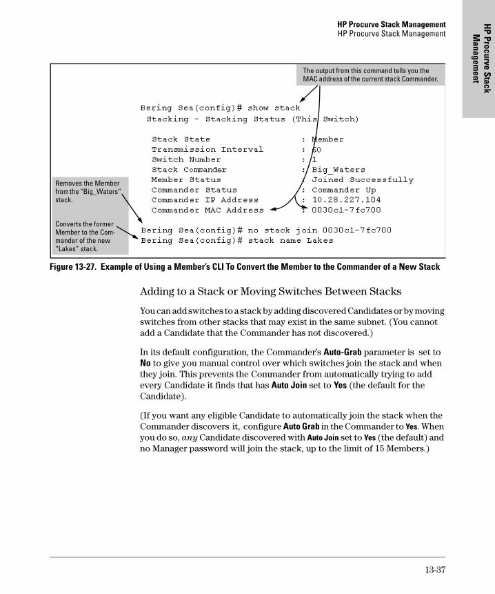
HP Procurve Stack ManagementHP Procurve Stack Management
HP Procurve Stack
Managem
ent
Figure 13-27. Example of Using a Member’s CLI To Convert the Member to the Commander of a New Stack
Adding to a Stack or Moving Switches Between Stacks
You can add switches to a stack by adding discovered Candidates or by moving switches from other stacks that may exist in the same subnet. (You cannot add a Candidate that the Commander has not discovered.)
In its default configuration, the Commander’s Auto-Grab parameter is set to No to give you manual control over which switches join the stack and when they join. This prevents the Commander from automatically trying to add every Candidate it finds that has Auto Join set to Yes (the default for the Candidate).
(If you want any eligible Candidate to automatically join the stack when the Commander discovers it, configure Auto Grab in the Commander to Yes. When you do so, any Candidate discovered with Auto Join set to Yes (the default) and no Manager password will join the stack, up to the limit of 15 Members.)
Removes the Member from the “Big_Waters” stack.
Converts the former Member to the Com- mander of the new “Lakes” stack.
The output from this command tells you the MAC address of the current stack Commander.
13-37
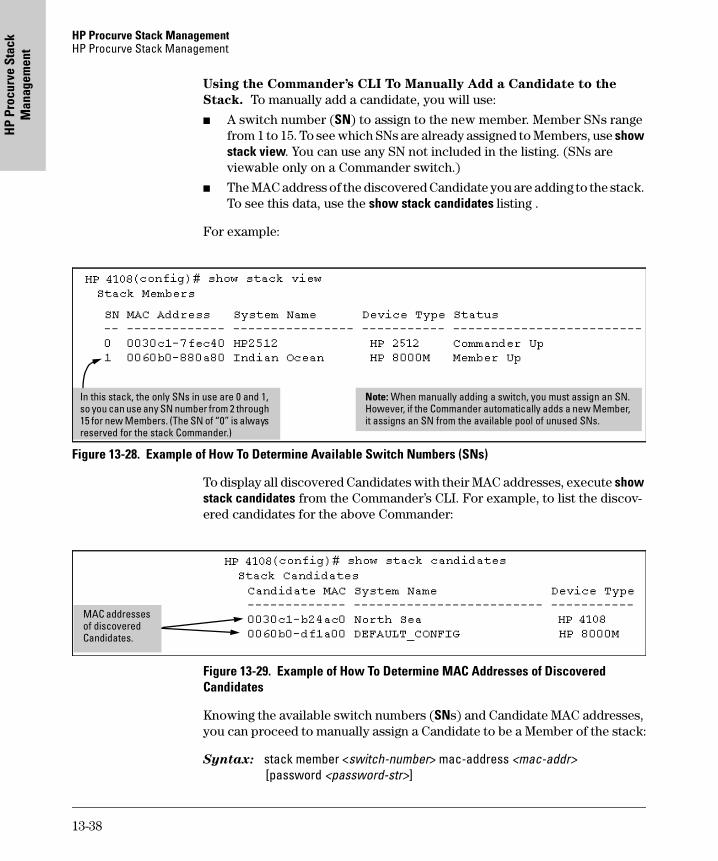
HP Procurve Stack Management HP Procurve Stack Management
HP
Proc
urve
Sta
ck
Man
agem
ent
Using the Commander’s CLI To Manually Add a Candidate to the
Stack. To manually add a candidate, you will use:
� A switch number (SN) to assign to the new member. Member SNs range from 1 to 15. To see which SNs are already assigned to Members, use show stack view. You can use any SN not included in the listing. (SNs are viewable only on a Commander switch.)
� The MAC address of the discovered Candidate you are adding to the stack. To see this data, use the show stack candidates listing .
For example:
Figure 13-28. Example of How To Determine Available Switch Numbers (SNs)
To display all discovered Candidates with their MAC addresses, execute show stack candidates from the Commander’s CLI. For example, to list the discov-ered candidates for the above Commander:
Figure 13-29. Example of How To Determine MAC Addresses of Discovered Candidates
Knowing the available switch numbers (SNs) and Candidate MAC addresses, you can proceed to manually assign a Candidate to be a Member of the stack:
Syntax: stack member <switch-number> mac-address <mac-addr> [password <password-str>]
Note: When manually adding a switch, you must assign an SN. However, if the Commander automatically adds a new Member, it assigns an SN from the available pool of unused SNs.
In this stack, the only SNs in use are 0 and 1, so you can use any SN number from 2 through 15 for new Members. (The SN of “0” is always reserved for the stack Commander.)
MAC addresses of discovered Candidates.
13-38
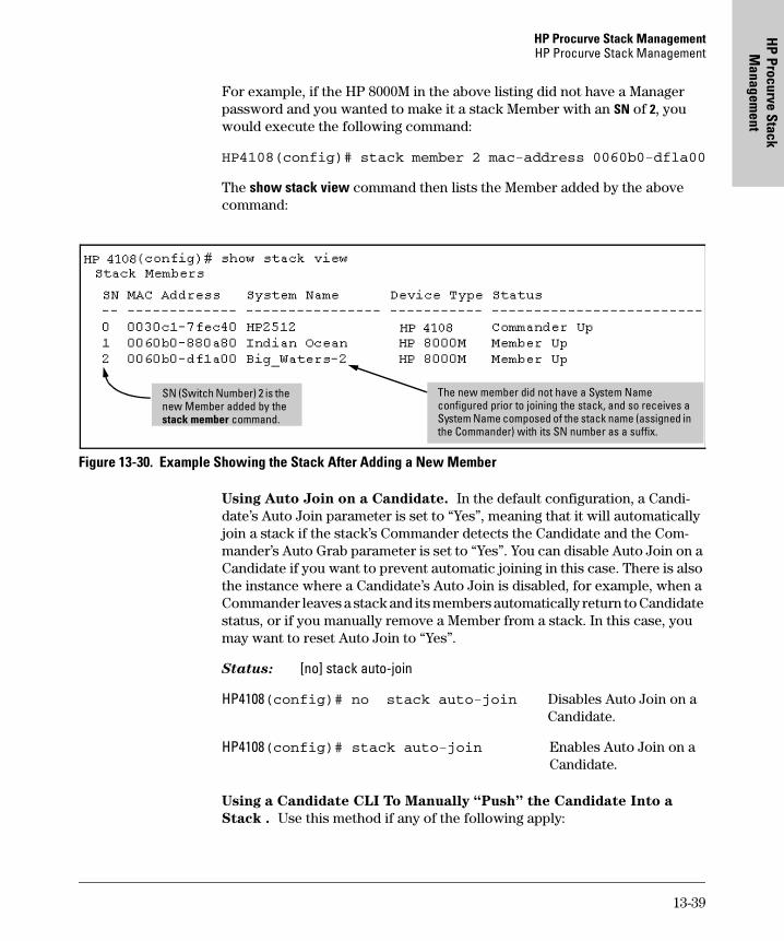
HP Procurve Stack ManagementHP Procurve Stack Management
HP Procurve Stack
Managem
ent
For example, if the HP 8000M in the above listing did not have a Manager password and you wanted to make it a stack Member with an SN of 2, you would execute the following command:
HP4108(config)# stack member 2 mac-address 0060b0-dfla00
The show stack view command then lists the Member added by the above command:
Figure 13-30. Example Showing the Stack After Adding a New Member
Using Auto Join on a Candidate. In the default configuration, a Candi-date’s Auto Join parameter is set to “Yes”, meaning that it will automatically join a stack if the stack’s Commander detects the Candidate and the Com-mander’s Auto Grab parameter is set to “Yes”. You can disable Auto Join on a Candidate if you want to prevent automatic joining in this case. There is also the instance where a Candidate’s Auto Join is disabled, for example, when a Commander leaves a stack and its members automatically return to Candidate status, or if you manually remove a Member from a stack. In this case, you may want to reset Auto Join to “Yes”.
Status: [no] stack auto-join
HP4108(config)# no stack auto-join Disables Auto Join on aCandidate.
HP4108(config)# stack auto-join Enables Auto Join on aCandidate.
Using a Candidate CLI To Manually “Push” the Candidate Into a
Stack . Use this method if any of the following apply:
SN (Switch Number) 2 is the new Member added by the stack member command.
The new member did not have a System Name configured prior to joining the stack, and so receives a System Name composed of the stack name (assigned in the Commander) with its SN number as a suffix.
13-39
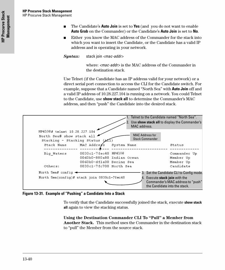
HP Procurve Stack Management HP Procurve Stack Management
HP
Proc
urve
Sta
ck
Man
agem
ent
� The Candidate’s Auto Join is set to Yes (and you do not want to enable Auto Grab on the Commander) or the Candidate’s Auto Join is set to No.
� Either you know the MAC address of the Commander for the stack into which you want to insert the Candidate, or the Candidate has a valid IP address and is operating in your network.
Syntax: stack join <mac-addr>
where: <mac-addr> is the MAC address of the Commander in the destination stack.
Use Telnet (if the Candidate has an IP address valid for your network) or a direct serial port connection to access the CLI for the Candidate switch. For example, suppose that a Candidate named “North Sea” with Auto Join off and a valid IP address of 10.28.227.104 is running on a network. You could Telnet to the Candidate, use show stack all to determine the Commander’s MAC address, and then “push” the Candidate into the desired stack.
Figure 13-31. Example of “Pushing” a Candidate Into a Stack
To verify that the Candidate successfully joined the stack, execute show stack all again to view the stacking status.
Using the Destination Commander CLI To “Pull” a Member from
Another Stack. This method uses the Commander in the destination stack to “pull” the Member from the source stack.
1. Telnet to the Candidate named “North Sea”.2. Use show stack all to display the Commander’s
MAC address.
3. Set the Candidate CLI to Config mode.4. Execute stack join with the
Commander’s MAC address to “push” the Candidate into the stack.
MAC Address for Stack Commander
13-40
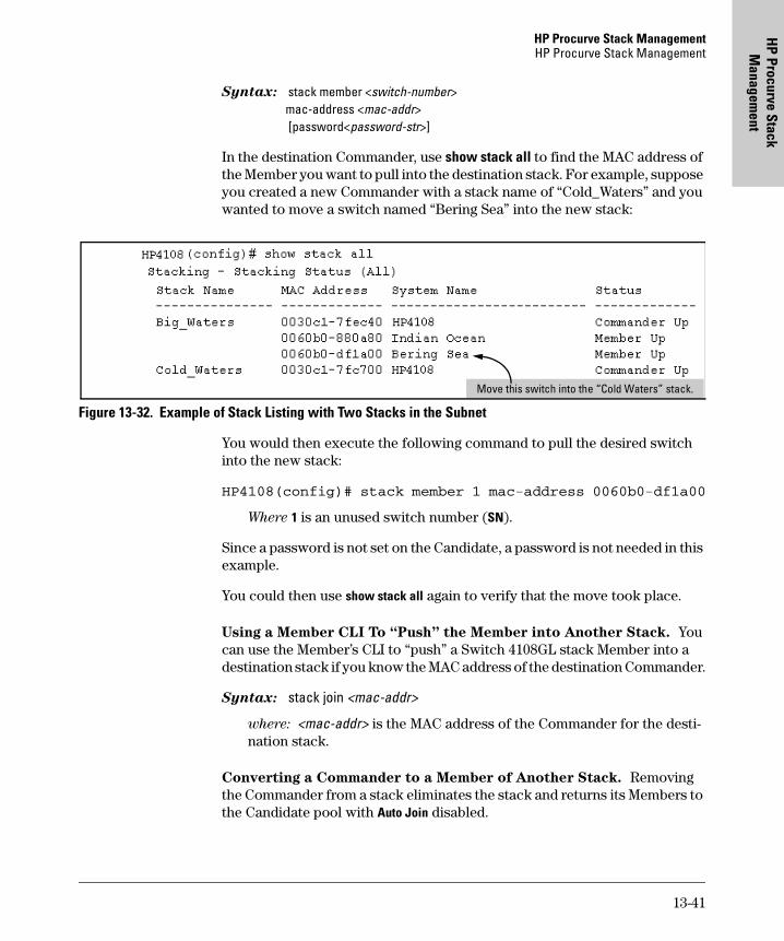
HP Procurve Stack ManagementHP Procurve Stack Management
HP Procurve Stack
Managem
ent
Syntax: stack member <switch-number> mac-address <mac-addr> [password<password-str>]
In the destination Commander, use show stack all to find the MAC address of the Member you want to pull into the destination stack. For example, suppose you created a new Commander with a stack name of “Cold_Waters” and you wanted to move a switch named “Bering Sea” into the new stack:
Figure 13-32. Example of Stack Listing with Two Stacks in the Subnet
You would then execute the following command to pull the desired switch into the new stack:
HP4108(config)# stack member 1 mac-address 0060b0-df1a00
Where 1 is an unused switch number (SN).
Since a password is not set on the Candidate, a password is not needed in this example.
You could then use show stack all again to verify that the move took place.
Using a Member CLI To “Push” the Member into Another Stack. You can use the Member’s CLI to “push” a Switch 4108GL stack Member into a destination stack if you know the MAC address of the destination Commander.
Syntax: stack join <mac-addr>
where: <mac-addr> is the MAC address of the Commander for the desti-nation stack.
Converting a Commander to a Member of Another Stack. Removing the Commander from a stack eliminates the stack and returns its Members to the Candidate pool with Auto Join disabled.
Move this switch into the “Cold Waters” stack.
13-41
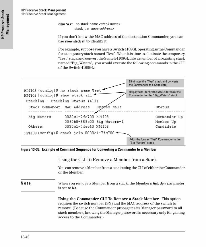
HP Procurve Stack Management HP Procurve Stack Management
HP
Proc
urve
Sta
ck
Man
agem
ent
Syntax: no stack name <stack name> stack join <mac-address>
If you don’t know the MAC address of the destination Commander, you can use show stack all to identify it.
For example, suppose you have a Switch 4108GL operating as the Commander for a temporary stack named “Test”. When it is time to eliminate the temporary “Test” stack and convert the Switch 4108GL into a member of an existing stack named “Big_Waters”, you would execute the following commands in the CLI of the Switch 4108GL:
Figure 13-33. Example of Command Sequence for Converting a Commander to a Member
Using the CLI To Remove a Member from a Stack
You can remove a Member from a stack using the CLI of either the Commander or the Member.
N o t e When you remove a Member from a stack, the Member’s Auto Join parameter is set to No.
Using the Commander CLI To Remove a Stack Member. This option requires the switch number (SN) and the MAC address of the switch to remove. (Because the Commander propagates its Manager password to all stack members, knowing the Manager password is necessary only for gaining access to the Commander.)
Eliminates the “Test” stack and converts the Commander to a Candidate.
Helps you to identify the MAC address of the Commander for the “Big_Waters” stack.
Adds the former “Test” Commander to the “Big_Waters” stack.
13-42
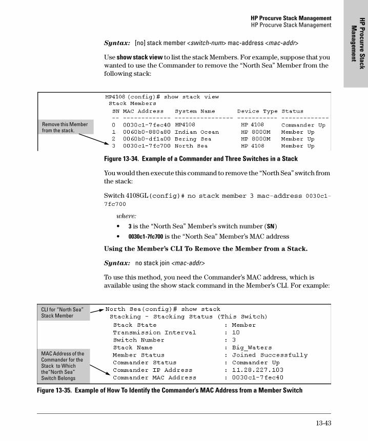
HP Procurve Stack ManagementHP Procurve Stack Management
HP Procurve Stack
Managem
ent
Syntax: [no] stack member <switch-num> mac-address <mac-addr>
Use show stack view to list the stack Members. For example, suppose that you wanted to use the Commander to remove the “North Sea” Member from the following stack:
Figure 13-34. Example of a Commander and Three Switches in a Stack
You would then execute this command to remove the “North Sea” switch from the stack:
Switch 4108GL(config)# no stack member 3 mac-address 0030c1-7fc700
where:
• 3 is the “North Sea” Member’s switch number (SN)
• 0030c1-7fc700 is the “North Sea” Member’s MAC address
Using the Member’s CLI To Remove the Member from a Stack.
Syntax: no stack join <mac-addr>
To use this method, you need the Commander’s MAC address, which is available using the show stack command in the Member’s CLI. For example:
Figure 13-35. Example of How To Identify the Commander’s MAC Address from a Member Switch
Remove this Member from the stack.
MAC Address of the Commander for the Stack to Which the“North Sea” Switch Belongs
CLI for “North Sea” Stack Member
13-43
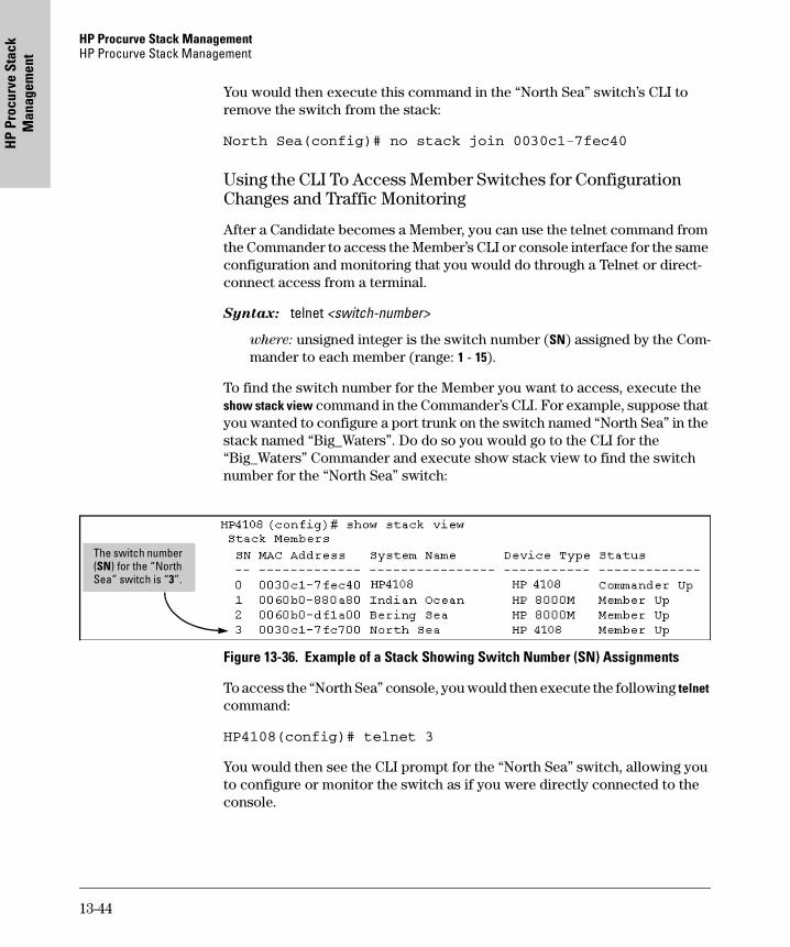
HP Procurve Stack Management HP Procurve Stack Management
HP
Proc
urve
Sta
ck
Man
agem
ent
You would then execute this command in the “North Sea” switch’s CLI to remove the switch from the stack:
North Sea(config)# no stack join 0030c1-7fec40
Using the CLI To Access Member Switches for Configuration Changes and Traffic Monitoring
After a Candidate becomes a Member, you can use the telnet command from the Commander to access the Member’s CLI or console interface for the same configuration and monitoring that you would do through a Telnet or direct-connect access from a terminal.
Syntax: telnet <switch-number>
where: unsigned integer is the switch number (SN) assigned by the Com-mander to each member (range: 1 - 15).
To find the switch number for the Member you want to access, execute the show stack view command in the Commander’s CLI. For example, suppose that you wanted to configure a port trunk on the switch named “North Sea” in the stack named “Big_Waters”. Do do so you would go to the CLI for the “Big_Waters” Commander and execute show stack view to find the switch number for the “North Sea” switch:
Figure 13-36. Example of a Stack Showing Switch Number (SN) Assignments
To access the “North Sea” console, you would then execute the following telnet command:
HP4108(config)# telnet 3
You would then see the CLI prompt for the “North Sea” switch, allowing you to configure or monitor the switch as if you were directly connected to the console.
The switch number (SN) for the “North Sea” switch is “3”.
13-44
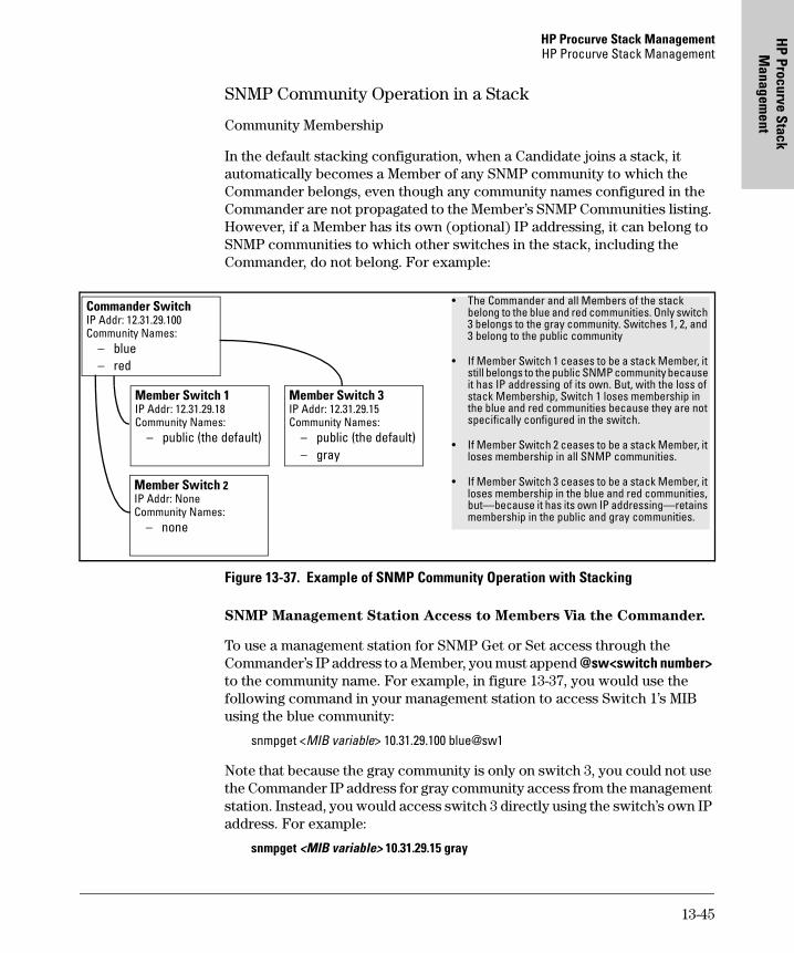
HP Procurve Stack ManagementHP Procurve Stack Management
HP Procurve Stack
Managem
ent
SNMP Community Operation in a Stack
Community Membership
In the default stacking configuration, when a Candidate joins a stack, it automatically becomes a Member of any SNMP community to which the Commander belongs, even though any community names configured in the Commander are not propagated to the Member’s SNMP Communities listing. However, if a Member has its own (optional) IP addressing, it can belong to SNMP communities to which other switches in the stack, including the Commander, do not belong. For example:
Figure 13-37. Example of SNMP Community Operation with Stacking
SNMP Management Station Access to Members Via the Commander.
To use a management station for SNMP Get or Set access through the Commander’s IP address to a Member, you must append @sw<switch number> to the community name. For example, in figure 13-37, you would use the following command in your management station to access Switch 1’s MIB using the blue community:
snmpget <MIB variable> 10.31.29.100 blue@sw1
Note that because the gray community is only on switch 3, you could not use the Commander IP address for gray community access from the management station. Instead, you would access switch 3 directly using the switch’s own IP address. For example:
snmpget <MIB variable> 10.31.29.15 gray
Commander SwitchIP Addr: 12.31.29.100Community Names:
– blue– red
Member Switch 2IP Addr: NoneCommunity Names:
– none
Member Switch 3IP Addr: 12.31.29.15Community Names:
– public (the default)– gray
Member Switch 1IP Addr: 12.31.29.18Community Names:
– public (the default)
• The Commander and all Members of the stack belong to the blue and red communities. Only switch 3 belongs to the gray community. Switches 1, 2, and 3 belong to the public community
• If Member Switch 1 ceases to be a stack Member, it still belongs to the public SNMP community because it has IP addressing of its own. But, with the loss of stack Membership, Switch 1 loses membership in the blue and red communities because they are not specifically configured in the switch.
• If Member Switch 2 ceases to be a stack Member, it loses membership in all SNMP communities.
• If Member Switch 3 ceases to be a stack Member, it loses membership in the blue and red communities, but—because it has its own IP addressing—retains membership in the public and gray communities.
13-45
HP Procurve Stack Management HP Procurve Stack Management
HP
Proc
urve
Sta
ck
Man
agem
ent
Note that in the above example (figure 13-37) you cannot use the public community through the Commander to access any of the Member switches. For example, you can use the public community to access the MIB in switches 1 and 3 by using their unique IP addresses. However, you must use the red or blue community to access the MIB for switch 2.
snmpget <MIB variable> 10.31.29.100 blue@sw2
Using the CLI To Disable or Re-Enable Stacking
In the default configuration, stacking is enabled on the Procurve Switch 4108GL. You can use the CLI to disable stacking on these switches at any time. Disabling stacking has the following effects:
� Disabling a Commander: Eliminates the stack, returns the stack Mem-bers to Candidates with Auto Join disabled, and changes the Commander to a stand-alone (nonstacking) switch. You must re-enable stacking on the switch before it can become a Candidate, Member, or Commander.
� Disabling a Member: Removes the Member from the stack and changes it to a stand-alone (nonstacking) switch. You must re-enable stacking on the switch before it can become a Candidate, Member, or Commander.
� Disabling a Candidate: Changes the Candidate to a stand-alone (non-stacking) switch.
Syntax: no stack (Disables stacking on the switch.) stack (Enables stacking on the switch.)
Transmission Interval
All switches in the stack must be set to the same transmission interval to help ensure proper stacking operation. HP recommends that you leave this param-eter set to the default 60 seconds.
Syntax: stack transmission-interval <seconds>
Stacking Operation with Multiple VLANs Configured
Stacking uses the primary VLAN in a switch. In the factory-default configura-tion, the DEFAULT_VLAN is the primary VLAN. However, you can designate any VLAN configured in the switch as the primary VLAN. (See “Which VLAN Is Primary?” on page 14-7.)
When using stacking in a multiple-VLAN environment, the following criteria applies:
13-46
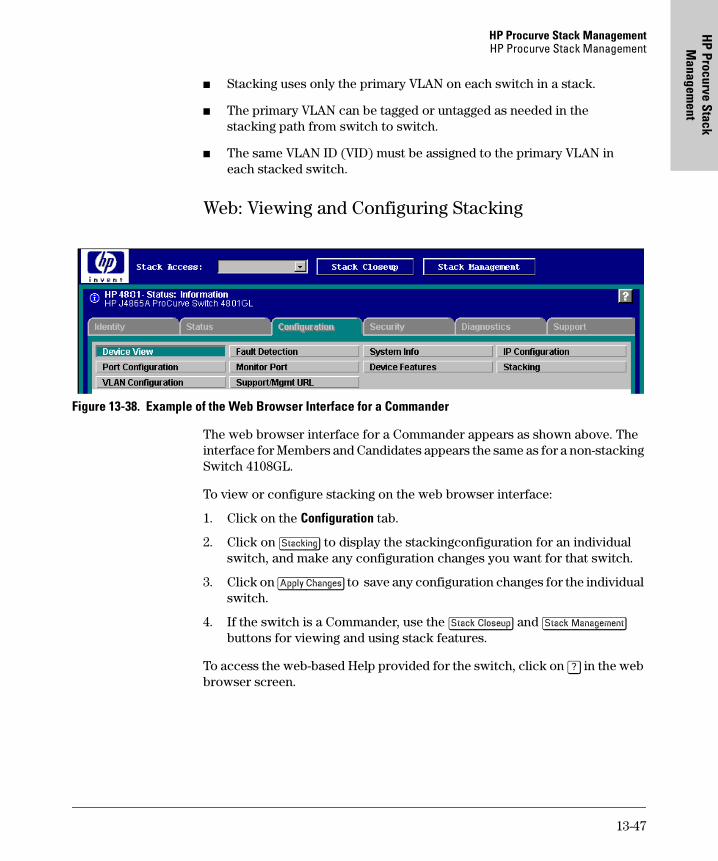
HP Procurve Stack ManagementHP Procurve Stack Management
HP Procurve Stack
Managem
ent
� Stacking uses only the primary VLAN on each switch in a stack.
� The primary VLAN can be tagged or untagged as needed in the stacking path from switch to switch.
� The same VLAN ID (VID) must be assigned to the primary VLAN in each stacked switch.
Web: Viewing and Configuring Stacking
Figure 13-38. Example of the Web Browser Interface for a Commander
The web browser interface for a Commander appears as shown above. The interface for Members and Candidates appears the same as for a non-stacking Switch 4108GL.
To view or configure stacking on the web browser interface:
1. Click on the Configuration tab.
2. Click on [Stacking] to display the stackingconfiguration for an individual switch, and make any configuration changes you want for that switch.
3. Click on [Apply Changes] to save any configuration changes for the individual switch.
4. If the switch is a Commander, use the [Stack Closeup] and [Stack Management] buttons for viewing and using stack features.
To access the web-based Help provided for the switch, click on [?] in the web browser screen.
13-47
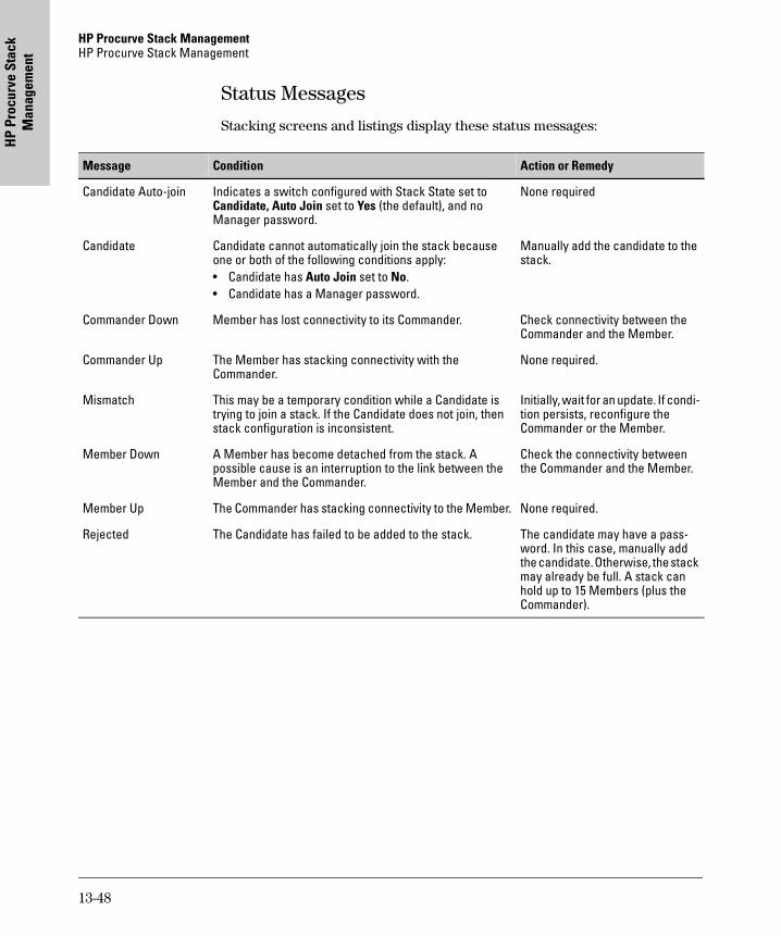
HP Procurve Stack Management HP Procurve Stack Management
HP
Proc
urve
Sta
ck
Man
agem
ent
Status Messages
Stacking screens and listings display these status messages:
Message Condition Action or Remedy
Candidate Auto-join Indicates a switch configured with Stack State set to Candidate, Auto Join set to Yes (the default), and no Manager password.
None required
Candidate Candidate cannot automatically join the stack because one or both of the following conditions apply:• Candidate has Auto Join set to No.• Candidate has a Manager password.
Manually add the candidate to the stack.
Commander Down Member has lost connectivity to its Commander. Check connectivity between the Commander and the Member.
Commander Up The Member has stacking connectivity with the Commander.
None required.
Mismatch This may be a temporary condition while a Candidate is trying to join a stack. If the Candidate does not join, then stack configuration is inconsistent.
Initially, wait for an update. If condi-tion persists, reconfigure the Commander or the Member.
Member Down A Member has become detached from the stack. A possible cause is an interruption to the link between the Member and the Commander.
Check the connectivity between the Commander and the Member.
Member Up The Commander has stacking connectivity to the Member. None required.
Rejected The Candidate has failed to be added to the stack. The candidate may have a pass-word. In this case, manually add the candidate. Otherwise, the stack may already be full. A stack can hold up to 15 Members (plus the Commander).
13-48
Port-Based Virtual LA
Ns
(VLAN
s) and GVRP
14
Port-Based Virtual LANs (VLANs) and GVRP
Contents
Overview . . . . . . . . . . . . . . . . . . . . . . . . . . . . . . . . . . . . . . . . . . . . . . . . . . . . 14-3
Port-Based Virtual LANs (Static VLANs) . . . . . . . . . . . . . . . . . . . . . . 14-4
Overview of Using VLANs . . . . . . . . . . . . . . . . . . . . . . . . . . . . . . . . . . . 14-7VLAN Support and the Default VLAN . . . . . . . . . . . . . . . . . . . . . . 14-7Which VLAN Is Primary? . . . . . . . . . . . . . . . . . . . . . . . . . . . . . . . . 14-7Per-Port Static VLAN Configuration Options . . . . . . . . . . . . . . . . 14-8General Steps for Using VLANs . . . . . . . . . . . . . . . . . . . . . . . . . . 14-10Notes on Using VLANs . . . . . . . . . . . . . . . . . . . . . . . . . . . . . . . . . 14-10
Menu: Configuring VLAN Parameters . . . . . . . . . . . . . . . . . . . . . . . . . 14-11To Change VLAN Support Settings . . . . . . . . . . . . . . . . . . . . . . . 14-11Adding or Editing VLAN Names . . . . . . . . . . . . . . . . . . . . . . . . . . 14-13Adding or Changing a VLAN Port Assignment . . . . . . . . . . . . . . 14-14
CLI: Configuring VLAN Parameters . . . . . . . . . . . . . . . . . . . . . . . . . . 14-16
Web: Viewing and Configuring VLAN Parameters . . . . . . . . . . . . . . 14-22
VLAN Tagging Information . . . . . . . . . . . . . . . . . . . . . . . . . . . . . . . . . 14-23
Effect of VLANs on Other Switch Features . . . . . . . . . . . . . . . . . . . . 14-27Spanning Tree Protocol Operation with VLANs . . . . . . . . . . . . 14-27IP Interfaces . . . . . . . . . . . . . . . . . . . . . . . . . . . . . . . . . . . . . . . . . . 14-27VLAN MAC Addresses . . . . . . . . . . . . . . . . . . . . . . . . . . . . . . . . . . 14-28Port Trunks . . . . . . . . . . . . . . . . . . . . . . . . . . . . . . . . . . . . . . . . . . . 14-28Port Monitoring . . . . . . . . . . . . . . . . . . . . . . . . . . . . . . . . . . . . . . . 14-28
VLAN Restrictions . . . . . . . . . . . . . . . . . . . . . . . . . . . . . . . . . . . . . . . . . 14-29
GVRP . . . . . . . . . . . . . . . . . . . . . . . . . . . . . . . . . . . . . . . . . . . . . . . . . . . . . . . 14-30
General Operation . . . . . . . . . . . . . . . . . . . . . . . . . . . . . . . . . . . . . . . . . 14-31
Per-Port Options for Handling GVRP “Unknown VLANs” . . . . . . . . 14-33
Per-Port Options for Dynamic VLAN Advertising and Joining . . . . 14-35
GVRP and VLAN Access Control . . . . . . . . . . . . . . . . . . . . . . . . . . . . . 14-36Port-Leave From a Dynamic VLAN . . . . . . . . . . . . . . . . . . . . . . . 14-36
Planning for GVRP Operation . . . . . . . . . . . . . . . . . . . . . . . . . . . . . . . 14-37
14-1

Port-Based Virtual LANs (VLANs) and GVRP Contents
Port
-Bas
ed V
irtu
al L
AN
s (V
LAN
s) a
nd G
VRP
Configuring GVRP On a Switch . . . . . . . . . . . . . . . . . . . . . . . . . . . . . . 14-37Menu: Viewing and Configuring GVRP . . . . . . . . . . . . . . . . . . . . 14-37CLI: Viewing and Configuring GVRP . . . . . . . . . . . . . . . . . . . . . . 14-39Web: Viewing and Configuring GVRP . . . . . . . . . . . . . . . . . . . . . 14-42
GVRP Operating Notes . . . . . . . . . . . . . . . . . . . . . . . . . . . . . . . . . . . . . 14-42
14-2
Port-Based Virtual LANs (VLANs) and GVRPOverview
Port-Based Virtual LA
Ns
(VLAN
s) and GVRP
Overview
This chapter describes the following features and how to configure them with the switch’s built-in interfaces:
� Port-Based VLANs — Page 14-4:
� GVRP — Page 14-30:
For general information on how to use the switch’s built-in interfaces, see:
� Chapter 2, “Using the Menu Interface”
� Chapter 3, “Using the Command Line Interface (CLI)”
� Chapter 4, “Using the HP Web Browser Interface
� Chapter 5, “Switch Memory and Configuration”
14-3
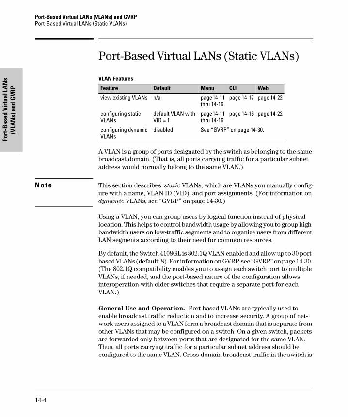
Port-Based Virtual LANs (VLANs) and GVRP Port-Based Virtual LANs (Static VLANs)
Port
-Bas
ed V
irtu
al L
AN
s (V
LAN
s) a
nd G
VRP
Port-Based Virtual LANs (Static VLANs)
VLAN Features
A VLAN is a group of ports designated by the switch as belonging to the same broadcast domain. (That is, all ports carrying traffic for a particular subnet address would normally belong to the same VLAN.)
N o t e This section describes static VLANs, which are VLANs you manually config-ure with a name, VLAN ID (VID), and port assignments. (For information on dynamic VLANs, see “GVRP” on page 14-30.)
Using a VLAN, you can group users by logical function instead of physical location. This helps to control bandwidth usage by allowing you to group high-bandwidth users on low-traffic segments and to organize users from different LAN segments according to their need for common resources.
By default, the Switch 4108GL is 802.1Q VLAN enabled and allow up to 30 port-based VLANs (default: 8). For information on GVRP, see “GVRP” on page 14-30. (The 802.1Q compatibility enables you to assign each switch port to multiple VLANs, if needed, and the port-based nature of the configuration allows interoperation with older switches that require a separate port for each VLAN.)
General Use and Operation. Port-based VLANs are typically used to enable broadcast traffic reduction and to increase security. A group of net-work users assigned to a VLAN form a broadcast domain that is separate from other VLANs that may be configured on a switch. On a given switch, packets are forwarded only between ports that are designated for the same VLAN. Thus, all ports carrying traffic for a particular subnet address should be configured to the same VLAN. Cross-domain broadcast traffic in the switch is
Feature Default Menu CLI Web
view existing VLANs n/a page 14-11 thru 14-16
page 14-17 page 14-22
configuring static VLANs
default VLAN with VID = 1
page 14-11 thru 14-16
page 14-16 page 14-22
configuring dynamic VLANs
disabled See “GVRP” on page 14-30.
14-4
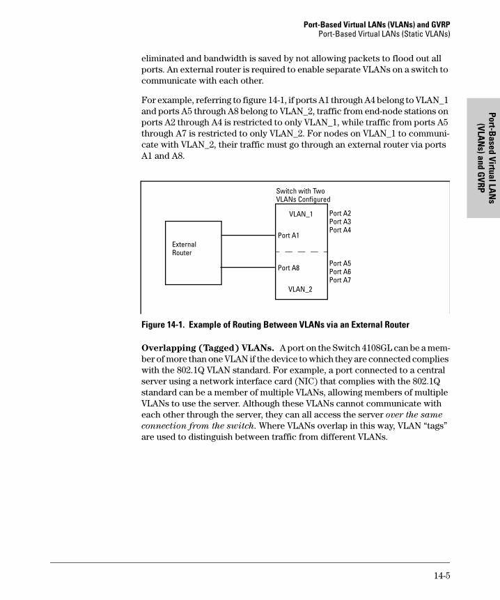
Port-Based Virtual LANs (VLANs) and GVRPPort-Based Virtual LANs (Static VLANs)
Port-Based Virtual LA
Ns
(VLAN
s) and GVRP
eliminated and bandwidth is saved by not allowing packets to flood out all ports. An external router is required to enable separate VLANs on a switch to communicate with each other.
For example, referring to figure 14-1, if ports A1 through A4 belong to VLAN_1 and ports A5 through A8 belong to VLAN_2, traffic from end-node stations on ports A2 through A4 is restricted to only VLAN_1, while traffic from ports A5 through A7 is restricted to only VLAN_2. For nodes on VLAN_1 to communi-cate with VLAN_2, their traffic must go through an external router via ports A1 and A8.
Figure 14-1. Example of Routing Between VLANs via an External Router
Overlapping (Tagged) VLANs. A port on the Switch 4108GL can be a mem-ber of more than one VLAN if the device to which they are connected complies with the 802.1Q VLAN standard. For example, a port connected to a central server using a network interface card (NIC) that complies with the 802.1Q standard can be a member of multiple VLANs, allowing members of multiple VLANs to use the server. Although these VLANs cannot communicate with each other through the server, they can all access the server over the same
connection from the switch. Where VLANs overlap in this way, VLAN “tags” are used to distinguish between traffic from different VLANs.
ExternalRouter
VLAN_2
VLAN_1
Port A1
Port A8
Port A2Port A3Port A4
Port A5Port A6Port A7
Switch with Two VLANs Configured
14-5
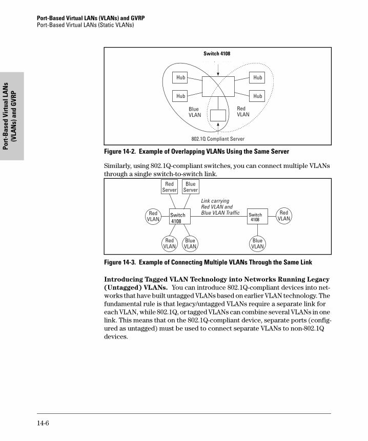
Port-Based Virtual LANs (VLANs) and GVRP Port-Based Virtual LANs (Static VLANs)
Port
-Bas
ed V
irtu
al L
AN
s (V
LAN
s) a
nd G
VRP
Figure 14-2. Example of Overlapping VLANs Using the Same Server
Similarly, using 802.1Q-compliant switches, you can connect multiple VLANs through a single switch-to-switch link.
Figure 14-3. Example of Connecting Multiple VLANs Through the Same Link
Introducing Tagged VLAN Technology into Networks Running Legacy
(Untagged) VLANs. You can introduce 802.1Q-compliant devices into net-works that have built untagged VLANs based on earlier VLAN technology. The fundamental rule is that legacy/untagged VLANs require a separate link for each VLAN, while 802.1Q, or tagged VLANs can combine several VLANs in one link. This means that on the 802.1Q-compliant device, separate ports (config-ured as untagged) must be used to connect separate VLANs to non-802.1Q devices.
Switch 4108
Switch 4108
Switch2524Switch 4108
14-6
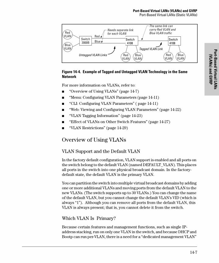
Port-Based Virtual LANs (VLANs) and GVRPPort-Based Virtual LANs (Static VLANs)
Port-Based Virtual LA
Ns
(VLAN
s) and GVRP
Figure 14-4. Example of Tagged and Untagged VLAN Technology in the Same Network
For more information on VLANs, refer to:
� “Overview of Using VLANs” (page 14-7)
� “Menu: Configuring VLAN Parameters (page 14-11)
� “CLI: Configuring VLAN Parameters” ( page 14-11)
� “Web: Viewing and Configuring VLAN Parameters” (page 14-22)
� “VLAN Tagging Information” (page 14-23)
� “Effect of VLANs on Other Switch Features” (page 14-27)
� “VLAN Restrictions” (page 14-29)
Overview of Using VLANs
VLAN Support and the Default VLAN
In the factory default configuration, VLAN support is enabled and all ports on the switch belong to the default VLAN (named DEFAULT_VLAN). This places all ports in the switch into one physical broadcast domain. In the factory-default state, the default VLAN is the primary VLAN.
You can partition the switch into multiple virtual broadcast domains by adding one or more additional VLANs and moving ports from the default VLAN to the new VLANs. (The switch supports up to 30 VLANs.) You can change the name of the default VLAN, but you cannot change the default VLAN’s VID (which is always “1”). Although you can remove all ports from the default VLAN, this VLAN is always present; that is, you cannot delete it from the switch.
Which VLAN Is Primary?
Because certain features and management functions, such as single IP-address stacking, run on only one VLAN in the switch, and because DHCP and Bootp can run per-VLAN, there is a need for a “dedicated management VLAN”
Non-802.1Q-compliant switch
Switch
Switch2524
Switch2524
Switch 4108
Switch 4108
Untagged VLAN Links
Tagged VLAN Link
14-7
Port-Based Virtual LANs (VLANs) and GVRP Port-Based Virtual LANs (Static VLANs)
Port
-Bas
ed V
irtu
al L
AN
s (V
LAN
s) a
nd G
VRP
to ensure that multiple instances of DHCP or Bootp on different VLANs do not result in conflicting configuration values for the switch. The primary VLAN is the VLAN the switch uses to run and manage these features and data. In the factory-default configuration, the switch designates the default VLAN (DEFAULT_VLAN) as the primary VLAN. However, to provide more control in your network, you can designate another VLAN as primary. To summarize, designating a non-default VLAN as primary means that:
� The stacking feature runs on the switch’s designated primary VLAN instead of the default VLAN
� The switch reads DHCP responses on the primary VLAN instead of on the default VLAN. (This includes such DHCP-resolved parameters as the TimeP server address, Default TTL, and IP addressing—including the Gateway IP address—when the switch configuration specifies DHCP as the source for these values.)
� The default VLAN continues to operate as a standard VLAN (except, as noted above, you cannot delete it or change its VID).
� Any ports not specifically assigned to another VLAN will remain assigned to the Default VLAN, regardless of whether it is the primary VLAN.
Candidates for primary VLAN include any static VLAN currently configured on the switch. (A dynamic—GVRP-learned—VLAN that has not been con-verted to a static VLAN cannot be the primary VLAN.) To display the current primary VLAN, use the CLI show vlan command.
N o t e If you configure a non-default VLAN as the primiary VLAN, you cannot delete that VLAN unless you first select a different VLAN to act as primary.
If you manually configure a gateway on the switch, it will ignore any gateway address received via DHCP or Bootp.
Per-Port Static VLAN Configuration Options
The following figure and table show the options you have for assigning individual ports to a static VLAN. Note that GVRP, if configured, affects these options and VLAN behaviour on the switch. The display below shows the per-port VLAN configuration options. Table 14-1 briefly describes these options.
14-8
Port-Based Virtual LANs (VLANs) and GVRPPort-Based Virtual LANs (Static VLANs)
Port-Based Virtual LA
Ns
(VLAN
s) and GVRP
Figure 14-5. Comparing Per-Port VLAN Options With and Without GVRP
Table 14-1. Per-Port VLAN Configuration Options
Example of Per-Port VLAN Configuration with GVRP Disabled
(the default)
Example of Per-Port VLAN Configuration with GVRP Enabled
Enabling GVRP causes “No” to display as “Auto”.
Parameter Effect on Port Participation in Designated VLAN
Tagged Allows the port to join multiple VLANs.
Untagged Allows VLAN connection to a device that is configured for an untagged VLAN instead of a tagged VLAN. The switch allows no more than one untagged VLAN assignment per port.
No - or -Auto
No: Appears when the switch is not GVRP-enabled; prevents the port from joining that VLAN.Auto: Appears when GVRP is enabled on the switch; allows the port to dynamically join any advertised VLAN that has the same VID
Forbid Prevents the port from joining the VLAN, regardless of whether GVRP is enabled on the switch.
14-9
Port-Based Virtual LANs (VLANs) and GVRP Port-Based Virtual LANs (Static VLANs)
Port
-Bas
ed V
irtu
al L
AN
s (V
LAN
s) a
nd G
VRP
General Steps for Using VLANs
1. Plan your VLAN strategy and create a map of the logical topology that will result from configuring VLANs. Include consideration for the interaction between VLANs and other features such as Spanning Tree Protocol, load balancing, and IGMP. (Refer to “Effect of VLANs on Other Switch Fea-tures” on page 14-27.) If you plan on using dynamic VLANs, include the port configuration planning necesary to support this feature. (See “GVRP” on page 14-30.)
By default, VLAN support is enabled and the switch is configured for eight VLANs.
2. Configure at least one VLAN in addition to the default VLAN.
3. Assign the desired switch ports to the new VLAN(s).
4. If you are managing VLANs with SNMP in an IP network, each VLAN must have an IP address. Refer to “IP Configuration” on “IP Configuration” on page 7-3.
Notes on Using VLANs
� If you are using DHCP/Bootp to acquire the switch’s configuration, packet time-to-live, and TimeP information, you must designate the VLAN on which DHCP is configured for this purpose as the primary VLAN. (In the factory-default configuration, the DEFAULT_VLAN is the primary VLAN.)
� IGMP, and some other features operate on a “per VLAN” basis. This means you must configure such features separately for each VLAN in which you want them to operate.
� You can rename the default VLAN, but you cannot change its VID (1) or delete it from the switch.
� Any ports not specifically assigned to another VLAN will remain assigned to the DEFAULT_VLAN.
� To delete a VLAN from the switch, you must first remove from that VLAN any ports assigned to it.
� Changing the number of VLANs supported on the switch requires a reboot. Other VLAN configuration changes are dynamic.
14-10
Port-Based Virtual LANs (VLANs) and GVRPPort-Based Virtual LANs (Static VLANs)
Port-Based Virtual LA
Ns
(VLAN
s) and GVRP
Menu: Configuring VLAN Parameters
In the factory default state, support is enabled for up to eight VLANs. (You can change the switch VLAN configuration to support up to 30 VLANs.) Also, all ports on the switch belong to the default VLAN (DEFAULT_VLAN) and are in the same broadcast/multicast domain. (The default VLAN is also the default primary VLAN—see “Which VLAN Is Primary?” on page 14-7.) In addition to the default VLAN, you can configure up to 29 other static VLANs by changing the “Maximum VLANs” parameter, adding new VLAN names and VIDs, and then assigning one or more ports to each VLAN. (The switch accepts a maximum of 30 VLANs, including the default VLAN and any dynamic VLANs the switch creates if you enable GVRP—page 14-30.) Note that each port can be assigned to multiple VLANs by using VLAN tagging. (See “VLAN Tagging Information” on page 14-23.)
To Change VLAN Support Settings
This section describes:
� Changing the maximum number of VLANs to support
� Changing the primary VLAN selection (See “Changing the Primary VLAN” on page 14-19.)
� Enabling or disabling dynamic VLANs (See “GVRP” on page 14-30.)
1. From the Main Menu select:
2. Switch Configuration8. VLAN Menu . . .
1. VLAN Support
You will then see the following screen:
Figure 14-6. The Default VLAN Support Screen
2. Press [E] (for Edit), then do one or more of the following:
14-11
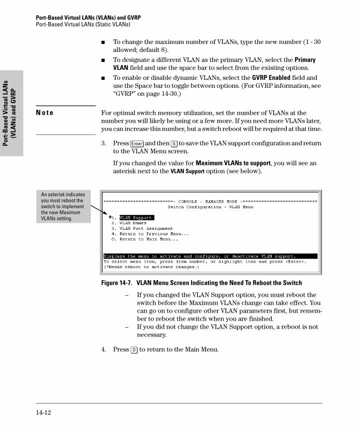
Port-Based Virtual LANs (VLANs) and GVRP Port-Based Virtual LANs (Static VLANs)
Port
-Bas
ed V
irtu
al L
AN
s (V
LAN
s) a
nd G
VRP
� To change the maximum number of VLANs, type the new number (1 - 30 allowed; default 8).
� To designate a different VLAN as the primary VLAN, select the Primary VLAN field and use the space bar to select from the existing options.
� To enable or disable dynamic VLANs, select the GVRP Enabled field and use the Space bar to toggle between options. (For GVRP information, see “GVRP” on page 14-30.)
N o t e For optimal switch memory utilization, set the number of VLANs at the number you will likely be using or a few more. If you need more VLANs later, you can increase this number, but a switch reboot will be required at that time.
3. Press [Enter] and then [S] to save the VLAN support configuration and return to the VLAN Menu screen.
If you changed the value for Maximum VLANs to support, you will see an asterisk next to the VLAN Support option (see below).
Figure 14-7. VLAN Menu Screen Indicating the Need To Reboot the Switch
– If you changed the VLAN Support option, you must reboot the switch before the Maximum VLANs change can take effect. You can go on to configure other VLAN parameters first, but remem-ber to reboot the switch when you are finished.
– If you did not change the VLAN Support option, a reboot is not necessary.
4. Press [0] to return to the Main Menu.
An asterisk indicates you must reboot the switch to implement the new Maximum VLANs setting.
14-12
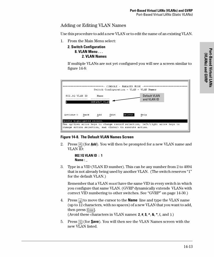
Port-Based Virtual LANs (VLANs) and GVRPPort-Based Virtual LANs (Static VLANs)
Port-Based Virtual LA
Ns
(VLAN
s) and GVRP
Adding or Editing VLAN Names
Use this procedure to add a new VLAN or to edit the name of an existing VLAN.
1. From the Main Menu select:
2. Switch Configuration8. VLAN Menu . . .
2. VLAN Names
If multiple VLANs are not yet configured you will see a screen similar to figure 14-8:
Figure 14-8. The Default VLAN Names Screen
2. Press [A] (for Add). You will then be prompted for a new VLAN name and VLAN ID:
802.1Q VLAN ID : 1Name : _
3. Type in a VID (VLAN ID number). This can be any number from 2 to 4094 that is not already being used by another VLAN. (The switch reserves “1” for the default VLAN.)
Remember that a VLAN must have the same VID in every switch in which you configure that same VLAN. (GVRP dynamically extends VLANs with correct VID numbering to other switches. See “GVRP” on page 14-30.)
4. Press [v] to move the cursor to the Name line and type the VLAN name (up to 12 characters, with no spaces) of a new VLAN that you want to add, then press [Enter]. (Avoid these characters in VLAN names: 2, #, $, ^, &, *, (, and ).)
5. Press [S] (for Save). You will then see the VLAN Names screen with the new VLAN listed.
Default VLAN and VLAN ID
14-13
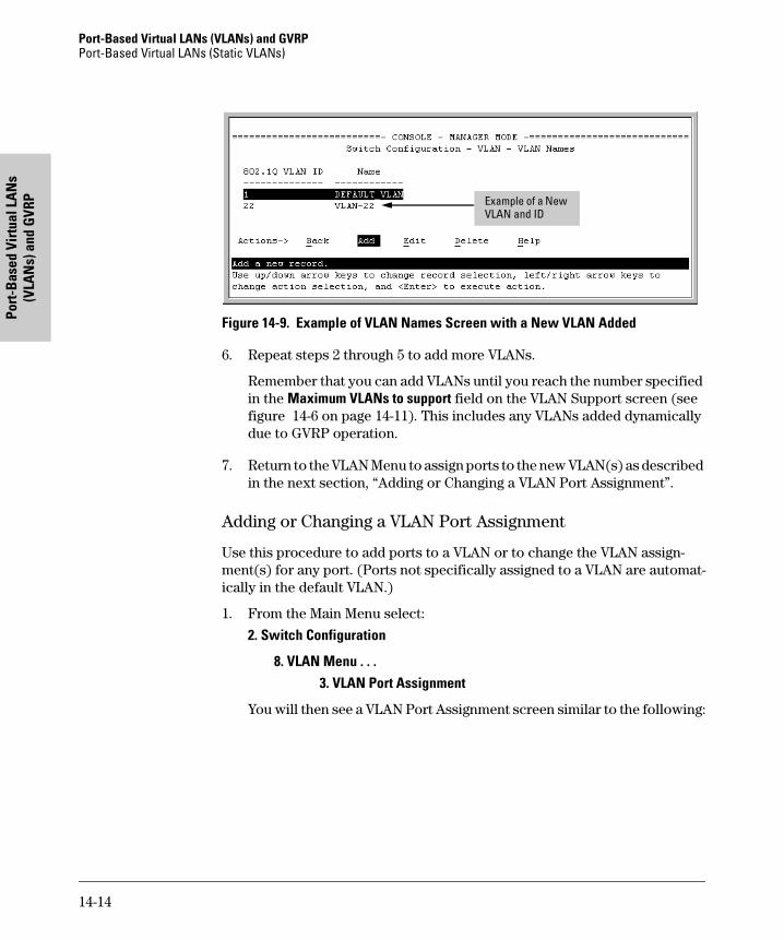
Port-Based Virtual LANs (VLANs) and GVRP Port-Based Virtual LANs (Static VLANs)
Port
-Bas
ed V
irtu
al L
AN
s (V
LAN
s) a
nd G
VRP
Figure 14-9. Example of VLAN Names Screen with a New VLAN Added
6. Repeat steps 2 through 5 to add more VLANs.
Remember that you can add VLANs until you reach the number specified in the Maximum VLANs to support field on the VLAN Support screen (see figure 14-6 on page 14-11). This includes any VLANs added dynamically due to GVRP operation.
7. Return to the VLAN Menu to assign ports to the new VLAN(s) as described in the next section, “Adding or Changing a VLAN Port Assignment”.
Adding or Changing a VLAN Port Assignment
Use this procedure to add ports to a VLAN or to change the VLAN assign-ment(s) for any port. (Ports not specifically assigned to a VLAN are automat-ically in the default VLAN.)
1. From the Main Menu select:
2. Switch Configuration
8. VLAN Menu . . . 3. VLAN Port Assignment
You will then see a VLAN Port Assignment screen similar to the following:
Example of a New VLAN and ID
14-14
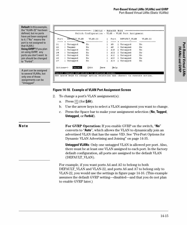
Port-Based Virtual LANs (VLANs) and GVRPPort-Based Virtual LANs (Static VLANs)
Port-Based Virtual LA
Ns
(VLAN
s) and GVRP
Figure 14-10. Example of VLAN Port Assignment Screen
2. To change a port’s VLAN assignment(s):
a. Press [E] (for Edit).
b. Use the arrow keys to select a VLAN assignment you want to change.
c. Press the Space bar to make your assignment selection (No, Tagged, Untagged, or Forbid).
N o t e For GVRP Operation: If you enable GVRP on the switch, “No” converts to “Auto”, which allows the VLAN to dynamically join an advertised VLAN that has the same VID. See “Per-Port Options for Dynamic VLAN Advertising and Joining” on page 14-35.
Untagged VLANs: Only one untagged VLAN is allowed per port. Also, there must be at least one VLAN assigned to each port. In the factory default configuration, all ports are assigned to the default VLAN (DEFAULT_VLAN).
For example, if you want ports A4 and A5 to belong to both DEFAULT_VLAN and VLAN-22, and ports A6 and A7 to belong only to VLAN-22, you would use the settings in figure page 14-16. (This example assumes the default GVRP setting—disabled—and that you do not plan to enable GVRP later.)
Default: In this example, the “VLAN-22” has been defined, but no ports have yet been assigned to it. (“No” means the port is not assigned to that VLAN.)Using GVRP? If you plan on using GVRP, any ports you don’t want to join should be changed to “Forbid”.
A port can be assigned to several VLANs, but only one of those assignments can be “Untagged”.
14-15
Port-Based Virtual LANs (VLANs) and GVRP Port-Based Virtual LANs (Static VLANs)
Port
-Bas
ed V
irtu
al L
AN
s (V
LAN
s) a
nd G
VRP
Figure 14-11. Example of VLAN Assignments for Specific Ports
For information on VLAN tags (“Untagged” and “Tagged”), refer to “VLAN Tagging Information” on page 14-23.
d. If you are finished assigning ports to VLANs, press [Enter] and then [S] (for Save) to activate the changes you've made and to return to the Configuration menu. (The console then returns to the VLAN menu.)
3. Return to the Main menu.
CLI: Configuring VLAN Parameters
In the factory default state, all ports on the switch belong to the default VLAN (DEFAULT_VLAN) and are in the same broadcast/multicast domain. (The default VLAN is also the default primary VLAN—see “Which VLAN Is Pri-mary?” on page 14-7.) You can configure up to 29 additional static VLANs by adding new VLAN names, and then assigning one or more ports to each VLAN. (The switch accepts a maximum of 30 VLANs, including the default VLAN and any dynamic VLANs the switch creates if you enable GVRP—page 14-30.) Note that each port can be assigned to multiple VLANs by using VLAN tagging. (See “VLAN Tagging Information” on page 14-23.)
Ports A4 and A5 are assigned to both VLANs.
Ports A6 and A7 are assigned only to VLAN-22.
All other ports are assigned only to the Default VLAN.
14-16
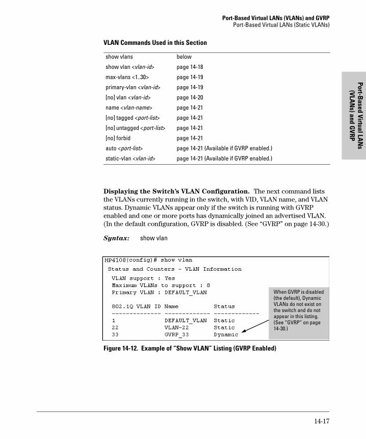
Port-Based Virtual LANs (VLANs) and GVRPPort-Based Virtual LANs (Static VLANs)
Port-Based Virtual LA
Ns
(VLAN
s) and GVRP
VLAN Commands Used in this Section
Displaying the Switch’s VLAN Configuration. The next command lists the VLANs currently running in the switch, with VID, VLAN name, and VLAN status. Dynamic VLANs appear only if the switch is running with GVRP enabled and one or more ports has dynamically joined an advertised VLAN. (In the default configuration, GVRP is disabled. (See “GVRP” on page 14-30.)
Syntax: show vlan
Figure 14-12. Example of “Show VLAN” Listing (GVRP Enabled)
show vlans below
show vlan <vlan-id> page 14-18
max-vlans <1..30> page 14-19
primary-vlan <vlan-id> page 14-19
[no] vlan <vlan-id> page 14-20
name <vlan-name> page 14-21
[no] tagged <port-list> page 14-21
[no] untagged <port-list> page 14-21
[no] forbid page 14-21
auto <port-list> page 14-21 (Available if GVRP enabled.)
static-vlan <vlan-id> page 14-21 (Available if GVRP enabled.)
When GVRP is disabled (the default), Dynamic VLANs do not exist on the switch and do not appear in this listing. (See “GVRP” on page 14-30.)
14-17
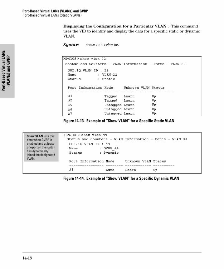
Port-Based Virtual LANs (VLANs) and GVRP Port-Based Virtual LANs (Static VLANs)
Port
-Bas
ed V
irtu
al L
AN
s (V
LAN
s) a
nd G
VRP
Displaying the Configuration for a Particular VLAN . This command uses the VID to identify and display the data for a specific static or dynamic VLAN.
Syntax: show vlan <vlan-id>
Figure 14-13. Example of “Show VLAN” for a Specific Static VLAN
Figure 14-14. Example of “Show VLAN” for a Specific Dynamic VLAN
Show VLAN lists this data when GVRP is enabled and at least one port on the switch has dynamically joined the designated VLAN.
14-18
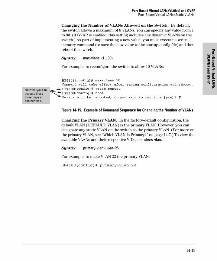
Port-Based Virtual LANs (VLANs) and GVRPPort-Based Virtual LANs (Static VLANs)
Port-Based Virtual LA
Ns
(VLAN
s) and GVRP
Changing the Number of VLANs Allowed on the Switch. By default, the switch allows a maximum of 8 VLANs. You can specify any value from 1 to 30. (If GVRP is enabled, this setting includes any dynamic VLANs on the switch.) As part of implementing a new value, you must execute a write memory command (to save the new value to the startup-config file) and then reboot the switch.
Syntax: max-vlans <1 .. 30>
For example, to reconfigure the switch to allow 10 VLANs:
Figure 14-15. Example of Command Sequence for Changing the Number of VLANs
Changing the Primary VLAN. In the factory-default configuration, the default VLAN (DEFAULT_VLAN) is the primary VLAN. However, you can designate any static VLAN on the switch as the primary VLAN. (For more on the primary VLAN, see “Which VLAN Is Primary?” on page 14-7.) To view the available VLANs and their respective VIDs, use show vlan.
Syntax: primary-vlan <vlan-id>
For example, to make VLAN 22 the primary VLAN:
HP4108(config)# primary-vlan 22
Note that you can execute these three steps at another time.
14-19
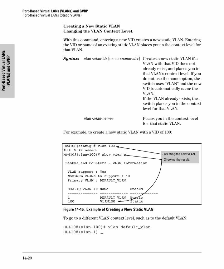
Port-Based Virtual LANs (VLANs) and GVRP Port-Based Virtual LANs (Static VLANs)
Port
-Bas
ed V
irtu
al L
AN
s (V
LAN
s) a
nd G
VRP
Creating a New Static VLAN
Changing the VLAN Context Level.
With this command, entering a new VID creates a new static VLAN. Entering the VID or name of an existing static VLAN places you in the context level for that VLAN.
Syntax: vlan <vlan-id> [name <name-str>] Creates a new static VLAN if aVLAN with that VID does notalready exist, and places you inthat VLAN’s context level. If youdo not use the name option, theswitch uses “VLAN” and the newVID to automatically name theVLAN.If the VLAN already exists, theswitch places you in the contextlevel for that VLAN.
vlan <vlan-name> Places you in the context levelfor that static VLAN.
For example, to create a new static VLAN with a VID of 100:
Figure 14-16. Example of Creating a New Static VLAN
To go to a different VLAN context level, such as to the default VLAN:
HP4108(vlan-100)# vlan default_vlan
HP4108(vlan-1) _
Creating the new VLAN.
Showing the result.
14-20
Port-Based Virtual LANs (VLANs) and GVRPPort-Based Virtual LANs (Static VLANs)
Port-Based Virtual LA
Ns
(VLAN
s) and GVRP
Converting a Dynamic VLAN to a Static VLAN. If GVRP is running on the switch and a port dynamically joins a VLAN, you can use the next command to convert the dynamic VLAN to a static VLAN. (For GVRP and dynamic VLAN operation, see “GVRP” on page 14-30.) This is necessary if you want to make the VLAN permanent. After you convert a dynamic VLAN to static, you must configure the switch’s per-port participation in the VLAN in the same way that you would for any static VLAN.
Syntax: static-vlan <vlan-id> (Use show vlan to list current VIDs.)
For example, suppose a dynamic VLAN with a VID of 125 exists on the switch. The following command converts the VLAN to a static VLAN.
HP4108(config)# static-vlan 125
Configuring Static VLAN Name and Per-Port Settings. The vlan <vlan-id> command, used with the options listed below, changes the name of an existing static VLAN and changes the per-port VLAN membership settings.
N o t e You can use these options from the configuration level by beginning the command with vlan <vlan-id>, or from the context level of the specific VLAN.
Syntax:name <vlan-name> Changes the name of the existing staticVLAN. (Avoid spaces and the following characters in the <vlan-name> entry: 2, #, $, ̂ ,&, *, (, and ).)
[no] tagged <port-list> Configures the indicated port(s) as Tagged for the specified VLAN. The“no” version sets the port(s) toeither No or (if GVRP is enabled) to Auto.
[no] untagged <port-list>Configures the indicated port(s) asUntagged for the specified VLAN. The“no” version sets the port(s) toeither No or (if GVRP is enabled) to Auto.
[no] forbid <port-list> Configures the indicated port(s) as “forbidden” to participate in the designated VLAN. The “no” version setsthe port(s) to either No or (if GVRP isenabled) to Auto.
auto <port-list> Available if GVRP is enabled on theswitch. Returns the per-port settingsfor the specified VLAN to Auto operation. Note that Auto is the defaultper-port setting for a static VLAN ifGVRP is runing on the switch.
14-21
Port-Based Virtual LANs (VLANs) and GVRP Port-Based Virtual LANs (Static VLANs)
Port
-Bas
ed V
irtu
al L
AN
s (V
LAN
s) a
nd G
VRP
(For information on dynamic VLAN and GVRP operation, see “GVRP” on page 14-30.)
For example, suppose you have a VLAN named VLAN100 with a VID of 100, and all ports are set to No for this VLAN. To change the VLAN name to “Blue_Team” and set ports 1-5 to Tagged, you could do so with these com-mands:
HP4108(config)# vlan 100 name Blue_Team
HP4108(config)# vlan 100 tagged 1-5
To move to the vlan 100 context level and execute the same commands:
HP4108(config)# vlan 100
HP4108(vlan-100)# name Blue_Team
HP4108(vlan-100)# tagged 1-5
Similarly, to change the tagged ports in the above examples to No (or Auto, if GVRP is enabled), you could use either of the following commands.
At the config level, use:HP4108(config)# no vlan 100 tagged 1-5
- or -
At the VLAN 100 context level, use:HP4108(vlan-100)# no tagged 1-5
N o t e You cannot use these commands with dynamic VLANs. Attempting to do so results in the message “VLAN already exists.” and no change occurs.
Web: Viewing and Configuring VLAN Parameters
In the web browser interface you can do the following:
� Add VLANs
� Rename VLANs
� Remove VLANs
� Configure GVRP mode
� Select a new Primary VLAN
To configure static VLAN port parameters, you will need to use the menu interface (available by Telnet from the web browser interface) or the CLI.
1. Click on the Configuration tab.
2. Click on [VLAN Configuration].
14-22
Port-Based Virtual LANs (VLANs) and GVRPPort-Based Virtual LANs (Static VLANs)
Port-Based Virtual LA
Ns
(VLAN
s) and GVRP
3. Click on [Add/Remove VLANs].
For web-based Help on how to use the web browser interface screen, click on the [?] button provided on the web browser screen.
VLAN Tagging Information
VLAN tagging enables traffic from more than one VLAN to use the same port. (Even when two or more VLANs use the same port they remain as separate domains and cannot receive traffic from each other without going through an external router.) As mentioned earlier, a “tag” is simply a unique VLAN identification number (VLAN ID, or VID) assigned to a VLAN at the time that you configure the VLAN name in the switch. In the Switch 4108GL the tag can be any number from 1 to 4094 that is not already assigned to a VLAN. When you subsequently assign a port to a given VLAN, you must implement the VLAN tag (VID) if the port will carry traffic for more than one VLAN. Otherwise, the port VLAN assignment can remain “untagged” because the tag is not needed. On a given switch, this means you should use the “Untagged” designation for a port VLAN assignment where the port is connected to non 802.1Q-compliant device or is assigned to only one VLAN. Use the “Tagged” designation when the port is assigned to more than one VLAN or the port is connected to a device that does comply with the 802.1Q standard.
For example, if port A7 on an 802.1Q-compliant switch is assigned to only the Red VLAN, the assignment can remain “untagged” because the port will forward traffic only for the Red VLAN. However, if both the Red and Green VLANs are assigned to port A7, then at least one of those VLAN assignments must be “tagged” so that Red VLAN traffic can be distinguished from Green VLAN traffic. The following illustration shows this concept:
14-23
Port-Based Virtual LANs (VLANs) and GVRP Port-Based Virtual LANs (Static VLANs)
Port
-Bas
ed V
irtu
al L
AN
s (V
LAN
s) a
nd G
VRP
Figure 14-17. Example of Tagged and Untagged VLAN Port Assignments� In switch X:
• VLANs assigned to ports X1 - X6 can all be untagged because there is only one VLAN assignment per port. Red VLAN traffic will go out only the Red ports; Green VLAN traffic will go out only the Green ports, and so on. Devices connected to these ports do not have to be 802.1Q-compliant.
• However, because both the Red VLAN and the Green VLAN are assigned to port X7, at least one of the VLANs must be tagged for this port.
� In switch Y:
• VLANs assigned to ports Y1 - Y4 can all be untagged because there is only one VLAN assignment per port. Devices connected to these ports do not have to be 802.1Q-compliant.
• Because both the Red VLAN and the Green VLAN are assigned to port Y5, at least one of the VLANs must be tagged for this port.
� In both switches: The ports on the link between the two switches must be configured the same. As shown in figure 14-17 (above), the Red VLAN must be untagged on port X7 and Y5 and the Green VLAN must be tagged on port X7 and Y5, or vice-versa.
BlueServer
WhiteServer
GreenServer
RedServer
RedVLAN
BlueVLAN
WhiteVLAN
GreenVLAN
GreenVLAN
RedVLAN
Switch"X"
5 6
7
4
13
2
Switch"Y"
5
4
1
3
2
Red VLAN: UntaggedGreen VLAN: Tagged
Ports 1-6: UntaggedPort 7: Red VLAN Untagged
Green VLAN Tagged
Ports 1-4: UntaggedPort 5: Red VLAN Untagged
Green VLAN Tagged
14-24
Port-Based Virtual LANs (VLANs) and GVRPPort-Based Virtual LANs (Static VLANs)
Port-Based Virtual LA
Ns
(VLAN
s) and GVRP
N o t e Each 802.1Q-compliant VLAN must have its own unique VID number, and that VLAN must be given the same VID in every device in which it is configured. That is, if the Red VLAN has a VID of 10 in switch X, then 10 must also be used for the Red VID in switch Y.
Figure 14-18. Example of VLAN ID Numbers Assigned in the VLAN Names Screen
VLAN tagging gives you several options:
� Since the purpose of VLAN tagging is to allow multiple VLANs on the same port, any port that has only one VLAN assigned to it can be configured as “Untagged” (the default).
� Any port that has two or more VLANs assigned to it can have one VLAN assignment for that port as “Untagged”. All other VLANs assigned to the same port must be configured as “Tagged”. (There can be no more than one Untagged VLAN on a port.)
� If all end nodes on a port comply with the 802.1Q standard and are configured to use the correct VID, then, you can configure all VLAN assignments on a port as “Tagged” if doing so makes it easier to manage your VLAN assignments, or for security reasons.
For example, in the following network, switches X and Y and servers S1 and S2 are 802.1Q-compliant. (Server S3 could also be 802.1Q-compliant, but it makes no difference for this example.)
VID Numbers
14-25
Port-Based Virtual LANs (VLANs) and GVRP Port-Based Virtual LANs (Static VLANs)
Port
-Bas
ed V
irtu
al L
AN
s (V
LAN
s) a
nd G
VRP
Figure 14-19. Example of Networked 802.1Q-Compliant Devices with Multiple VLANs on Some Ports
The VLANs assigned to ports X3, X4, Y2, Y3, and Y4 can all be untagged because there is only one VLAN assigned per port. Port X1 has multiple VLANs assigned, which means that one VLAN assigned to this port can be untagged and any others must be tagged. The same applies to ports X2, Y1, and Y5.
N o t e VLAN configurations on ports connected by the same link must match. Because ports X2 and Y5 are opposite ends of the same point-to-point connec-tion, both ports must have the same VLAN configuration; that is, both ports configure the Red VLAN as “Untagged” and the Green VLAN as “Tagged”.
Red VLAN: Untagged
Red VLAN: Untagged Red VLAN: Untagged
Green VLAN: Tagged
Green VLAN: Tagged Green VLAN: Tagged
Green VLAN only
ServerS1
ServerS2
ServerS3
GreenVLAN
GreenVLAN
RedVLAN
RedVLAN
Switch"X"
X1
X2
X3X4
Switch"Y"
Y1
Y4
Y2Y5
Y3
Switch X Switch Y
Port Red VLAN Green VLAN Port Red VLAN Green VLAN
X1 Untagged Tagged Y1 Untagged Tagged
X2 Untagged Tagged Y2 No* Untagged
X3 No* Untagged Y3 No* Untagged
X4 Untagged No* Y4 Untagged No*
Y5 Untagged Tagged
*”No” means the port is not a member of that VLAN. For example, port X3 is not a member of the Red VLAN and does not carry Red VLAN traffic. Also, if GVRP were enabled, “Auto” would appear instead of “No”.
14-26
Port-Based Virtual LANs (VLANs) and GVRPPort-Based Virtual LANs (Static VLANs)
Port-Based Virtual LA
Ns
(VLAN
s) and GVRP
To summarize:
Effect of VLANs on Other Switch Features
Spanning Tree Protocol Operation with VLANs
Because the Switch 4108GL follows the 802.1Q VLAN recommendation to use single-instance spanning tree, STP operates across all ports on the switch (regardless of VLAN assignments) instead of on a per-VLAN basis. This means that if redundant physical links exist between the switch and another 802.1Q device, all but one link will be blocked, regardless of whether the redundant links are in separate VLANs. However, you can use port trunking to prevent STP from unnecessarily blocking ports (and to improve overall network performance). Refer to “STP Operation with 802.1Q VLANs” on page 16-12.
Note that STP operates differently in different devices. For example, in the (non-802.1Q) HP Switch 2000 and the HP Switch 800T, STP operates on a per-VLAN basis, allowing redundant physical links as long as they are in separate VLANs.
IP Interfaces
There is a one-to-one relationship between a VLAN and an IP network inter-face. Since the VLAN is defined by a group of ports, the state (up/down) of those ports determines the state of the IP network interface associated with that VLAN. When a VLAN comes up because one or more of its ports is up, the IP interface for that VLAN is also activated. Likewise, when a VLAN is deactivated because all of its ports are down, the corresponding IP interface is also deactivated.
VLANs Per Port
Tagging Scheme
1 Untagged or Tagged. If the device connected to the port is 802.1Q-compliant, then the recommended choice is “Tagged”.
2 or More 1 VLAN Untagged; all others Tagged orAll VLANs Tagged
A given VLAN must have the same VID on any 802.1Q-compliant device in which the VLAN is configured.The ports connecting two 802.1Q devices should have identical VLAN configurations, as shown for ports X2 and Y5, above.
14-27
Port-Based Virtual LANs (VLANs) and GVRP Port-Based Virtual LANs (Static VLANs)
Port
-Bas
ed V
irtu
al L
AN
s (V
LAN
s) a
nd G
VRP
VLAN MAC Addresses
The switch has one unique MAC address for each of its VLAN interfaces. You can send an 802.2 test packet to this MAC address to verify connectivity to the switch. Likewise, you can assign an IP address to the VLAN interface, and when you Ping that address, ARP will resolve the IP address to this MAC address. The switch allows up to 30 VLAN MAC addresses (one per possible VLAN).
Port Trunks
When assigning a port trunk to a VLAN, all ports in the trunk are automatically assigned to the same VLAN. You cannot split trunk members across multiple VLANs. Also, a port trunk is tagged, untagged, or excluded from a VLAN in the same way as for individual, untrunked ports.
Port Monitoring
If you designate a port on the switch for network monitoring, this port will appear in the Port VLAN Assignment screen and can be configured as a member of any VLAN. For information on how broadcast, multicast, and unicast packets are tagged inside and outside of the VLAN to which the monitor port is assigned, see 18-11.
14-28
Port-Based Virtual LANs (VLANs) and GVRPPort-Based Virtual LANs (Static VLANs)
Port-Based Virtual LA
Ns
(VLAN
s) and GVRP
VLAN Restrictions
� A port must be a member of at least one VLAN. In the factory default configuration, all ports are assigned to the default VLAN (DEFAULT_VLAN; VID = 1).
� A port can be assigned to several VLANs, but only one of those assign-ments can be untagged. (The “Untagged” designation enables VLAN oper-ation with non 802.1Q-compliant devices.)
� An external router must be used to communicate between tagged VLANs on the switch.
� Before you can delete a VLAN, you must first re-assign all ports in the VLAN to another VLAN.
HP Router Requirements. Use the Hewlett-Packard version A.09.70 (or
later) router OS release if any of the following Hewlett-Packard routers are
installed in networks in which you will be using VLANs:
HP Router 440 (formerly Router ER)HP Router 470 (formerly Router LR)HP Router 480 (formerly Router BR)HP Router 650
Release A.09.74 is available on the World Wide Web at
http://www.hp.com/go/procurve
14-29
Port-Based Virtual LANs (VLANs) and GVRP GVRP
Port
-Bas
ed V
irtu
al L
AN
s (V
LAN
s) a
nd G
VRP
GVRP
GVRP—GARP VLAN Registration Protocol—is an application of the Generic Attribute Registration Protocol—GARP. GVRP is defined in the IEEE 802.1Q standard, and GARP is defined in the IEEE 802.1D-1998 standard.
N o t e To understand and use GVRP you must have a working knowledge of 802.1Q VLAN tagging. (See “Port-Based Virtual LANs (Static VLANs)” on page 14-4.)
GVRP uses “GVRP Bridge Protocol Data Units” (“GVRP BPDUs”) to “adver-tise” static VLANs. In this manual, a GVRP BPDU is termed an advertisement.
GVRP enables the Switch 4108GL to dynamically create 802.1Q-compliant VLANs on links with other devices running GVRP. This enables the switch to automatically create VLAN links between GVRP-aware devices. (A GVRP link can include intermediate devices that are not GVRP-aware.) This operation reduces the chances for errors in VLAN configuration by automatically pro-viding VLAN ID (VID) consistency across the network. That is, you can use GVRP to propagate VLANs to other GVRP-aware devices instead of manually having to set up VLANs across your network. After the switch creates a dynamic VLAN, you can optionally use the CLI static <vlan-id> command to convert it to a static VLAN or allow it to continue as a dynamic VLAN for as long as needed. You can also use GVRP to dynamically enable port member-ship in static VLANs configured on a switch.
Feature Default Menu CLI Web
view GVRP configuration n/a page 14-37 page 14-39 page 14-42
list static and dynamic VLANs on a GVRP-enabled switch
n/a — page 14-41 page 14-42
enable or disable GVRP on the switch
disabled page 14-37 page 14-40 page 14-42
enable or disable GVRP on individual ports
enabled page 14-37 page 14-40 —
control how individual ports will handle advertisements for new VLANs
Learn page 14-37 page 14-40 page 14-42
convert a dynamic VLAN to a static VLAN
n/a — page 14-42 —
configure static VLANs DEFAULT_VLAN (VID = 1)
page 14-11 page 14-16 page 14-42
14-30
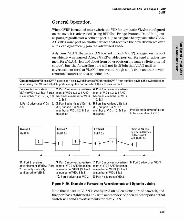
Port-Based Virtual LANs (VLANs) and GVRPGVRP
Port-Based Virtual LA
Ns
(VLAN
s) and GVRP
General Operation
When GVRP is enabled on a switch, the VID for any static VLANs configured on the switch is advertised (using BPDUs—Bridge Protocol Data Units) out all ports, regardless of whether a port is up or assigned to any particular VLAN. A GVRP-aware port on another device that receives the advertisements over a link can dynamically join the advertised VLAN.
A dynamic VLAN (that is, a VLAN learned through GVRP) is tagged on the port on which it was learned. Also, a GVRP-enabled port can forward an advertise-ment for a VLAN it learned about from other ports on the same switch (internal source), but the forwarding port will not itself join that VLAN until an advertisement for that VLAN is received through a link from another device (external source) on that specific port.
Figure 14-20. Example of Forwarding Advertisements and Dynamic Joining
Note that if a static VLAN is configured on at least one port of a switch, and that port has established a link with another device, then all other ports of that switch will send advertisements for that VLAN.
Operating Note: When a GVRP-aware port on a switch learns a VID through GVRP from another device, the switch begins advertising that VID out all of its ports except the port on which the VID was learned.
Core switch with static VLANs (VID= 1, 2, & 3). Port 2 is a member of VIDs 1, 2, & 3.
1. Port 2 advertises VIDs 1, 2, & 3.
2. Port 1 receives advertise-ment of VIDs 1, 2, & 3 AND becomes a member of VIDs 1, 2, & 3.3. Port 3 advertises VIDs 1, 2, & 3, but port 3 is NOT a member of VIDs 1, 2, & 3 at this point.
4. Port 4 receives advertise-ment of VIDs 1, 2, & 3 AND becomes a member of VIDs 1, 2, & 3.5. Port 5 advertises VIDs 1, 2, & 3, but port 5 is NOT a member of VIDs 1, 2, & 3 at this point.
Port 6 is statically configured to be a member of VID 3.
11. Port 2 receives advertisement of VID 3. (Port 2 is already statically configured for VID 3.)
9. Port 3 receives advertise-ment of VID 3 AND becomes a member of VID 3. (Still not a member of VIDs 1 & 2.)10. Port 1 advertises VID 3.
7. Port 5 receives advertise-ment of VID 3 AND becomes a member of VID 3. (Still not a member of VIDs 1 & 2.)8. Port 4 advertises VID 3.
6. Port 6 advertises VID 3.
Switch 1
GVRP On
2
Switch 2
GVRP On
31
Switch 3
GVRP On
54
Static VLAN con-figured End Device (NIC or switch) with GVRP On
6
14-31
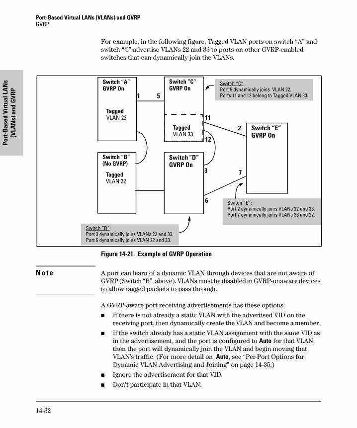
Port-Based Virtual LANs (VLANs) and GVRP GVRP
Port
-Bas
ed V
irtu
al L
AN
s (V
LAN
s) a
nd G
VRP
For example, in the following figure, Tagged VLAN ports on switch “A” and switch “C” advertise VLANs 22 and 33 to ports on other GVRP-enabled switches that can dynamically join the VLANs.
Figure 14-21. Example of GVRP Operation
N o t e A port can learn of a dynamic VLAN through devices that are not aware of GVRP (Switch “B”, above). VLANs must be disabled in GVRP-unaware devices to allow tagged packets to pass through.
A GVRP-aware port receiving advertisements has these options:
� If there is not already a static VLAN with the advertised VID on the receiving port, then dynamically create the VLAN and become a member.
� If the switch already has a static VLAN assignment with the same VID as in the advertisement, and the port is configured to Auto for that VLAN, then the port will dynamically join the VLAN and begin moving that VLAN’s traffic. (For more detail on Auto, see “Per-Port Options for Dynamic VLAN Advertising and Joining” on page 14-35.)
� Ignore the advertisement for that VID.
� Don’t participate in that VLAN.
Switch “A”GVRP On
Switch “B”(No GVRP)
Switch “C”GVRP On
Switch “D”GVRP On
Tagged VLAN 22
Tagged VLAN 22
Switch “E”GVRP On
Tagged VLAN 33
Switch “C”: Port 5 dynamically joins VLAN 22.Ports 11 and 12 belong to Tagged VLAN 33.
Switch “E”:Port 2 dynamically joins VLANs 22 and 33.Port 7 dynamically joins VLANs 33 and 22.
Switch “D”:Port 3 dynamically joins VLANs 22 and 33.Port 6 dynamically joins VLAN 22 and 33.
1 5
12
11
2
73
6
14-32
Port-Based Virtual LANs (VLANs) and GVRPGVRP
Port-Based Virtual LA
Ns
(VLAN
s) and GVRP
Note also that a port belonging to a Tagged or Untagged static VLAN has these configurable options:
� Send VLAN advertisements, and also receive advertisements for VLANs on other ports and dynamically join those VLANs.
� Send VLAN advertisements, but ignore advertisements received from other ports.
� Avoid GVRP participation by not sending advertisements and dropping any advertisements received from other devices.
IP Addressing. A dynamic VLAN does not have an IP address, and moves traffic on the basis of port membership in VLANs. However, after GVRP creates a dynamic VLAN, you can convert it to a static VLAN. Note that it is then necessary to assign ports to the VLAN in the same way that you would for a static VLAN that you created manually. In the static state you can configure IP addressing on the VLAN and access it in the same way that you would any other static (manually created) VLAN.
Per-Port Options for Handling GVRP “Unknown VLANs”
An “unknown VLAN” is a VLAN that the switch learns of by receiving an advertisement for that VLAN on a port that is not already a member of that VLAN. If the port is configured to learn unknown VLANs, then the VLAN is dynamically created and the port becomes a tagged member of the VLAN. For example, suppose that in figure 14-21 (page 14-32), port 1 on switch “A” is connected to port 5 on switch “C”. Because switch “A” has VLAN 22 statically configured, while switch “C” does not have this VLAN statically configured (and does not “Forbid” VLAN 22 on port 5), VLAN 22 is handled as an “Unknown VLAN” on port 5 in switch “C”. Conversely, if VLAN 22 was statically configured on switch C, but port 5 was not a member, port 5 would become a member when advertisements for VLAN 22 were received from switch “A”.
When you enable GVRP on a switch, you have the per-port join-request options listed in table 14-2:
14-33
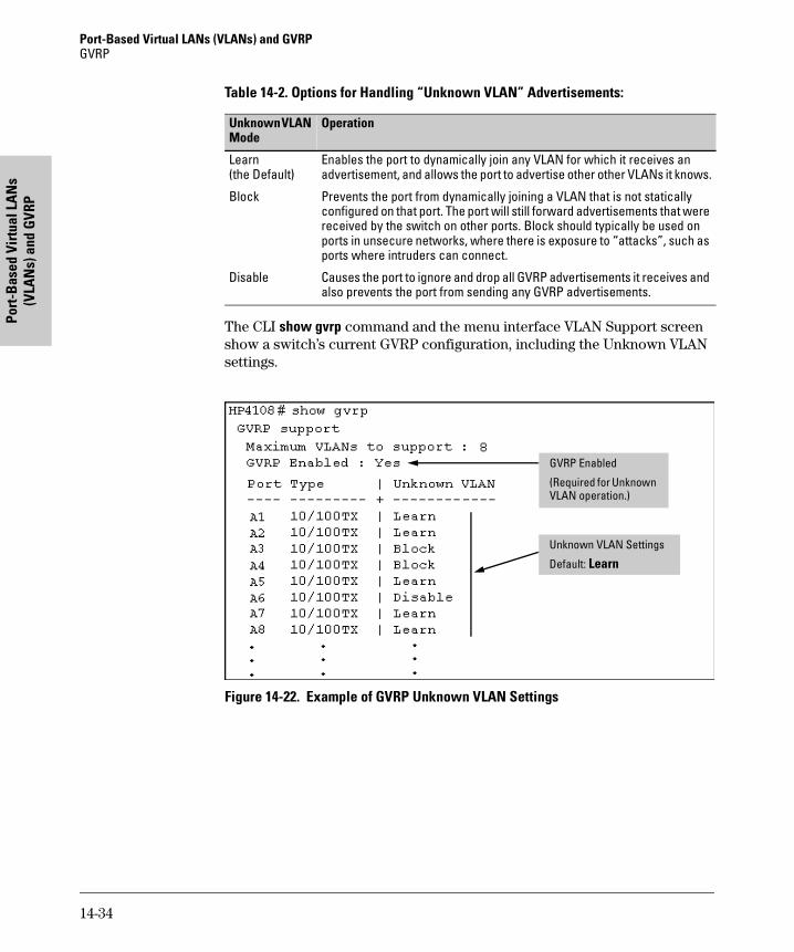
Port-Based Virtual LANs (VLANs) and GVRP GVRP
Port
-Bas
ed V
irtu
al L
AN
s (V
LAN
s) a
nd G
VRP
Table 14-2. Options for Handling “Unknown VLAN” Advertisements:
The CLI show gvrp command and the menu interface VLAN Support screen show a switch’s current GVRP configuration, including the Unknown VLAN settings.
Figure 14-22. Example of GVRP Unknown VLAN Settings
Unknown VLAN Mode
Operation
Learn(the Default)
Enables the port to dynamically join any VLAN for which it receives an advertisement, and allows the port to advertise other other VLANs it knows.
Block Prevents the port from dynamically joining a VLAN that is not statically configured on that port. The port will still forward advertisements that were received by the switch on other ports. Block should typically be used on ports in unsecure networks, where there is exposure to “attacks”, such as ports where intruders can connect.
Disable Causes the port to ignore and drop all GVRP advertisements it receives and also prevents the port from sending any GVRP advertisements.
GVRP Enabled
(Required for Unknown VLAN operation.)
Unknown VLAN Settings
Default: Learn
14-34
Port-Based Virtual LANs (VLANs) and GVRPGVRP
Port-Based Virtual LA
Ns
(VLAN
s) and GVRP
Per-Port Options for Dynamic VLAN Advertising and JoiningInitiating Advertisements. As described in the preceding section, to enable dynamic joins, GVRP must be enabled and a port must be configured to Learn (the default). However, to send advertisements in your network, one or more Tagged or Untagged static VLANs must be configured on one or more switches (with GVRP enabled), depending on your topology.
Enabling a Port for Dynamic Joins. You can configure a port to dynami-cally join a static VLAN. The join will then occur if that port subsequently receives an advertisement for the static VLAN. (This is done by using the Auto and Learn options described in table 14-3, below.
Parameters for Controlling VLAN Propagation Behavior. You can con-figure an individual port to actively or passively participate in dynamic VLAN propagation or to ignore dynamic VLAN (GVRP) operation. These options are controlled by the GVRP “Unknown VLAN” and the static VLAN configuration parameters, as described in the following table:
Table 14-3. Controlling VLAN Behavior on Ports with Static VLANs
Per-Port “Unknown VLAN” (GVRP) Configuration
Static VLAN Options—Per Specified VLAN on Each Port 1
Port Activity:Tagged or Untagged (Per VLAN)2
Port Activity: Auto2 (Per VLAN)
Port Activity: Forbid (Per VLAN)2
Learn(the Default)
Generate advertisements.Forward outbound advertisements for other VLANs.
Receive advertisements and forward them to other ports on the switch for outbound transmission. Allow the port to dynamically join the specified VLAN if the port receives an advertisement for that VLAN.
Do not allow the specified VLAN on this port.
Block Generate advertisements.Forward outbound advertisements received from other ports on the switch for other VLANs.
Receive advertisements and forward them to other ports on the switch for outbound transmission. Do not dynamically join the VLAN.
Do not allow the specified VLAN on this port.Drop all GVRP VLAN advertisements.
Disable Ignore GVRP and drop all GVRP advertisements.
Ignore GVRP and drop all GVRP advertisements.
Do not allow the VLAN on this port.
1 Each port of a Switch 4108GL must be a Tagged or Untagged member of at least one VLAN. Thus, any port configured for GVRP to Learn or Block will generate and forward advertisements for static VLAN(s) configured on the switch and also for dynamic VLANs the switch learns on other ports. .
2 To configure tagging, Auto, or Forbid, see “Configuring Static VLAN Name and Per-Port Settings” on page 14-21 (for the CLI) or “Adding or Changing a VLAN Port Assignment” on page 14-14 (for the menu).
14-35
Port-Based Virtual LANs (VLANs) and GVRP GVRP
Port
-Bas
ed V
irtu
al L
AN
s (V
LAN
s) a
nd G
VRP
As the preceeding table indicates, when you enable GVRP, a port that has a Tagged or Untagged static VLAN has the option for both generating advertise-ments and dynamically joining other VLANs.
N o t e In table 14-3, above, the Unknown VLAN parameters are configured on a per-port basis using the CLI. The Tagged, Untagged, Auto, and Forbid options are configured per static VLAN on every port, using either the menu interface or the CLI.
Because dynamic VLANs operate as Tagged VLANs, and because a tagged port on one device cannot communicate with an untagged port on another device, HP recommends that you use Tagged VLANs for the static VLANs you will use to generate advertisements.
GVRP and VLAN Access Control
When you enable GVRP on a switch, the default GVRP parameter settings allow all of the switch’s ports to transmit and receive dynamic VLAN adver-tisements (GVRP advertisements) and to dynamically join VLANs. The two preceding sections describe the per-port features you can use to control and limit VLAN propagation. To summarize, you can:
� Allow a port to advertise and/or join dynamic VLANs (Learn mode—the default).
� Allow a port to send VLAN advertisements, but not receive them from other devices; that is, the port cannot dynamically join a VLAN but other devices can dynamically join the VLANs it advertises (Block mode).
� Prevent a port from participating in GVRP operation (Disable mode).
Port-Leave From a Dynamic VLAN
A dynamic VLAN continues to exist on a port for as long as the port continues to receive advertisements of that VLAN from another device connected to that port or until you:
� Convert the VLAN to a static VLAN (See “Converting a Dynamic VLAN to a Static VLAN” on page 14-21.)
� Reconfigure the port to Block or Disable
� Disable GVRP
� Reboot the switch
The time-to-live for dynamic VLANs is 10 seconds. That is, if a port has not received an advertisement for an existing dynamic VLAN during the last 10 seconds, the port removes itself from that dynamic VLAN.
14-36
Port-Based Virtual LANs (VLANs) and GVRPGVRP
Port-Based Virtual LA
Ns
(VLAN
s) and GVRP
Planning for GVRP Operation
These steps outline the procedure for setting up dynamic VLANs for a seg-ment.
1. Determine the VLAN topology you want for each segment (broadcast domain) on your network.
2. Determine the VLANs that must be static and the VLANs that can be dynamically propagated.
3. Determine the device or devices on which you must manually create static VLANs in order to propagate VLANs throughout the segment.
4. Determine security boundaries and how the individual ports in the seg-ment will handle dynamic VLAN advertisements. (See table 14-2 on page 14-34 and table 14-3 on page 14-35.)
5. Enable GVRP on all devices you want to use with dynamic VLANs and configure the appropriate “Unknown VLAN” parameter (Learn, Block, or Disable) for each port.
6. Configure the static VLANs on the switch(es) where they are needed, along with the per-VLAN parameters (Tagged, Untagged, Auto, and Forbid—see table 14-3 on page 14-35) on each port.
7. Dynamic VLANs will then appear automatically, according to the config-uration options you have chosen.
8. Convert dynamic VLANs to static VLANs where you want dynamic VLANs to become permanent.
Configuring GVRP On a Switch
The procedures in this section describe how to:
� View the GVRP configuration on a switch
� Enable and disable GVRP on a switch
� Specify how individual ports will handle advertisements
To view or configure static VLANs for GVRP operation, refer to “Per-Port Static VLAN Configuration Options” on page 14-8.
Menu: Viewing and Configuring GVRP
1. From the Main Menu, select:
14-37
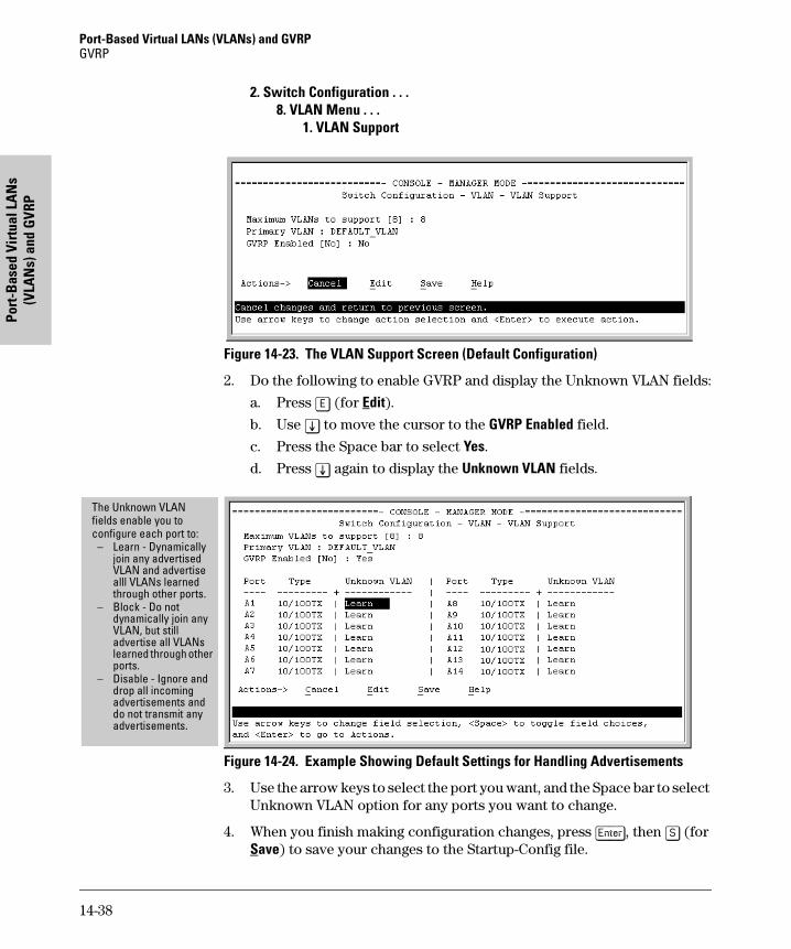
Port-Based Virtual LANs (VLANs) and GVRP GVRP
Port
-Bas
ed V
irtu
al L
AN
s (V
LAN
s) a
nd G
VRP
2. Switch Configuration . . .8. VLAN Menu . . .
1. VLAN Support
Figure 14-23. The VLAN Support Screen (Default Configuration)
2. Do the following to enable GVRP and display the Unknown VLAN fields:
a. Press [E] (for Edit).
b. Use [v] to move the cursor to the GVRP Enabled field.
c. Press the Space bar to select Yes.
d. Press [v] again to display the Unknown VLAN fields.
Figure 14-24. Example Showing Default Settings for Handling Advertisements
3. Use the arrow keys to select the port you want, and the Space bar to select Unknown VLAN option for any ports you want to change.
4. When you finish making configuration changes, press [Enter], then [S] (for Save) to save your changes to the Startup-Config file.
The Unknown VLAN fields enable you to configure each port to:
– Learn - Dynamically join any advertised VLAN and advertise alll VLANs learned through other ports.
– Block - Do not dynamically join any VLAN, but still advertise all VLANs learned through other ports.
– Disable - Ignore and drop all incoming advertisements and do not transmit any advertisements.
14-38
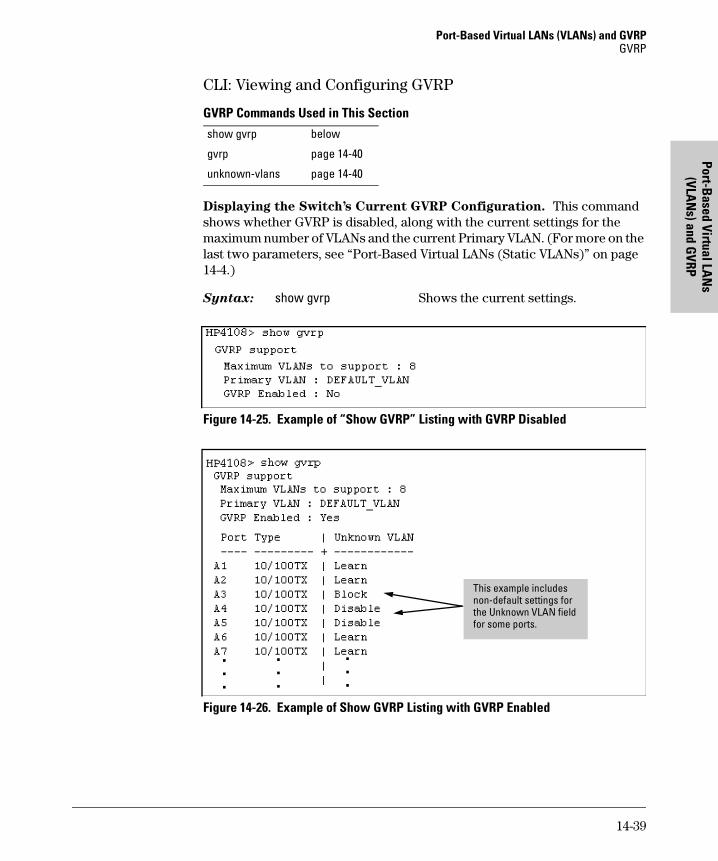
Port-Based Virtual LANs (VLANs) and GVRPGVRP
Port-Based Virtual LA
Ns
(VLAN
s) and GVRP
CLI: Viewing and Configuring GVRP
GVRP Commands Used in This Section
Displaying the Switch’s Current GVRP Configuration. This command shows whether GVRP is disabled, along with the current settings for the maximum number of VLANs and the current Primary VLAN. (For more on the last two parameters, see “Port-Based Virtual LANs (Static VLANs)” on page 14-4.)
Syntax: show gvrp Shows the current settings.
Figure 14-25. Example of “Show GVRP” Listing with GVRP Disabled
Figure 14-26. Example of Show GVRP Listing with GVRP Enabled
show gvrp below
gvrp page 14-40
unknown-vlans page 14-40
This example includes non-default settings for the Unknown VLAN field for some ports.
14-39
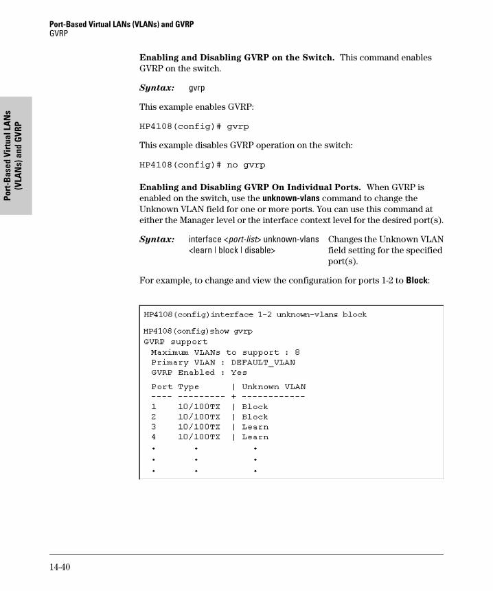
Port-Based Virtual LANs (VLANs) and GVRP GVRP
Port
-Bas
ed V
irtu
al L
AN
s (V
LAN
s) a
nd G
VRP
Enabling and Disabling GVRP on the Switch. This command enables GVRP on the switch.
Syntax: gvrp
This example enables GVRP:
HP4108(config)# gvrp
This example disables GVRP operation on the switch:
HP4108(config)# no gvrp
Enabling and Disabling GVRP On Individual Ports. When GVRP is enabled on the switch, use the unknown-vlans command to change the Unknown VLAN field for one or more ports. You can use this command at either the Manager level or the interface context level for the desired port(s).
Syntax: interface <port-list> unknown-vlans Changes the Unknown VLAN<learn | block | disable> field setting for the specified
port(s).
For example, to change and view the configuration for ports 1-2 to Block:
14-40
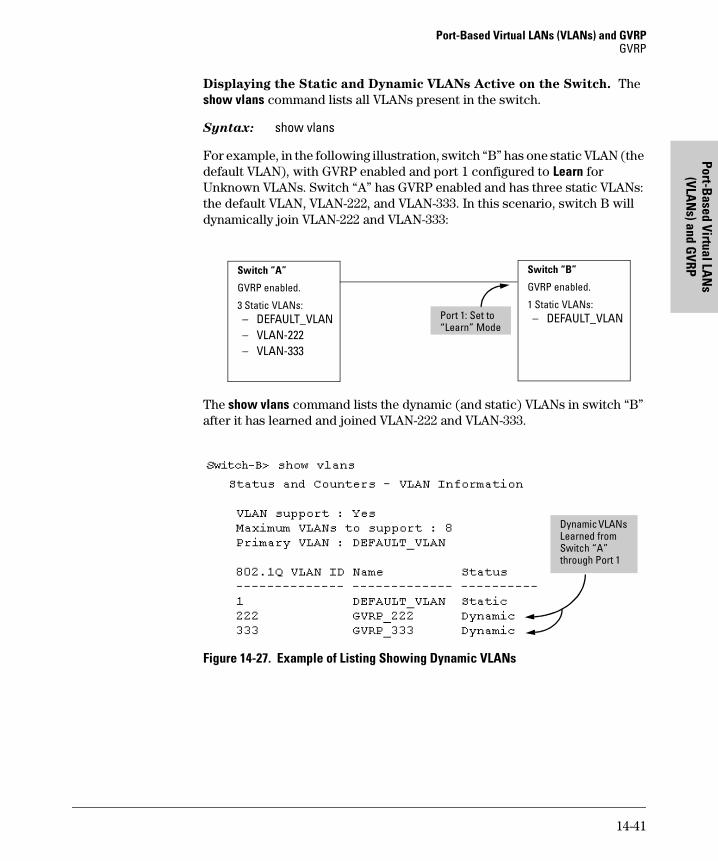
Port-Based Virtual LANs (VLANs) and GVRPGVRP
Port-Based Virtual LA
Ns
(VLAN
s) and GVRP
Displaying the Static and Dynamic VLANs Active on the Switch. The show vlans command lists all VLANs present in the switch.
Syntax: show vlans
For example, in the following illustration, switch “B” has one static VLAN (the default VLAN), with GVRP enabled and port 1 configured to Learn for Unknown VLANs. Switch “A” has GVRP enabled and has three static VLANs: the default VLAN, VLAN-222, and VLAN-333. In this scenario, switch B will dynamically join VLAN-222 and VLAN-333:
The show vlans command lists the dynamic (and static) VLANs in switch “B” after it has learned and joined VLAN-222 and VLAN-333.
Figure 14-27. Example of Listing Showing Dynamic VLANs
Switch “A”
GVRP enabled.
3 Static VLANs:– DEFAULT_VLAN– VLAN-222– VLAN-333
Switch “B”
GVRP enabled.
1 Static VLANs:– DEFAULT_VLANPort 1: Set to
“Learn” Mode
Dynamic VLANs Learned from Switch “A” through Port 1
14-41
Port-Based Virtual LANs (VLANs) and GVRP GVRP
Port
-Bas
ed V
irtu
al L
AN
s (V
LAN
s) a
nd G
VRP
Converting a Dynamic VLAN to a Static VLAN. If a port on the switch has joined a dynamic VLAN, you can use the following command to convert that dynamic VLAN to a static VLAN:
Syntax: static <dynamic-vlan-id>
For example, to convert dynamic VLAN 333 (from the previous example) to a static VLAN:
HP4108(config)# static 333
When you convert a dynamic VLAN to a static VLAN, all ports on the switch are assigned to the VLAN in Auto mode.
Web: Viewing and Configuring GVRP
To view, enable, disable, or reconfigure GVRP:
1. Click on the Configuration tab.
2. Click on [VLAN Configuration] and do the following:
• To enable or disable GVRP, click on GVRP Enabled.
• To change the Unknown VLAN field for any port:i. Click on [GVRP Security] and make the desired changes.ii. Click on [Apply] to save and implement your changes to the
Unknown VLAN fields.
For web-based Help on how to use the web browser interface screen, click on the [?] button provided on the web browser screen.
GVRP Operating Notes
� A dynamic VLAN must be converted to a static VLAN before it can have an IP address.
� The total number of VLANs on the switch (static and dynamic combined) cannot exceed the current Maximum VLANs setting. For example, in the factory default state, the switch supports eight VLANs. Thus, in a case where four static VLANs are configured on the switch, the switch can accept up to four additional VLANs in any combination of static and dynamic. Any additional VLANs advertised to the switch will not be added unless you first increase the Maximum VLANs setting. In the Menu inter-face, click on 2. Switch Configuration ... | 8. VLAN Menu | 1. VLAN Support. In the global config level of the CLI, use max-vlans.
14-42
Port-Based Virtual LANs (VLANs) and GVRPGVRP
Port-Based Virtual LA
Ns
(VLAN
s) and GVRP
� Converting a dynamic VLAN to a static VLAN and then executing the write memory command saves the VLAN in the startup-config file and makes it a permanent part of the switch’s VLAN configuration.
� Within the same broadcast domain, a dynamic VLAN can pass through a device that is not GVRP-aware. This is because a hub or a switch that is not GVRP-ware will flood the GVRP (multicast) advertisement packets out all ports.
� GVRP assigns dynamic VLANs as Tagged VLANs. To configure the VLAN as Untagged, you must first convert it to a static VLAN.
� Rebooting a switch on which a dynamic VLAN exists deletes that VLAN. However, the dynamic VLAN re-appears after the reboot if GVRP is enabled and the switch again receives advertisements for that VLAN through a port configured to add dynamic VLANs.
� By receiving advertisements from other devices running GVRP, the switch learns of static VLANs on those other devices and dynamically (automat-ically) creates tagged VLANs on the links to the advertising devices. Similarly, the switch advertises its static VLANs to other GVRP-aware devices, as well as the dynamic VLANs the switch has learned.
� A GVRP-enabled switch does not advertise any GVRP-learned VLANs out of the port(s) on which it originally learned of those VLANs.
14-43

Port-Based Virtual LANs (VLANs) and GVRP GVRP
Port
-Bas
ed V
irtu
al L
AN
s (V
LAN
s) a
nd G
VRP
14-44
Multim
edia Traffic Control w
ith IP Multicast (IG
MP)
15
Multimedia Traffic Control with IP Multicast (IGMP)
Chapter Contents
Chapter Contents . . . . . . . . . . . . . . . . . . . . . . . . . . . . . . . . . . . . . . . . . . . . . . 15-1
Overview . . . . . . . . . . . . . . . . . . . . . . . . . . . . . . . . . . . . . . . . . . . . . . . . . . . . . 15-2
General Operation and Features . . . . . . . . . . . . . . . . . . . . . . . . . . . . . . . . . 15-3
IGMP Terms . . . . . . . . . . . . . . . . . . . . . . . . . . . . . . . . . . . . . . . . . . . . . . . 15-4
IGMP Operating Features . . . . . . . . . . . . . . . . . . . . . . . . . . . . . . . . . . . . 15-5Basic Operation . . . . . . . . . . . . . . . . . . . . . . . . . . . . . . . . . . . . . . . . 15-5Enhancements . . . . . . . . . . . . . . . . . . . . . . . . . . . . . . . . . . . . . . . . . 15-5
CLI: Configuring and Displaying IGMP . . . . . . . . . . . . . . . . . . . . . . . . . . . . 15-6
How IGMP Operates . . . . . . . . . . . . . . . . . . . . . . . . . . . . . . . . . . . . . . . . . . 15-11
Operation With or Without IP Addressing . . . . . . . . . . . . . . . . . . . . . 15-12
Automatic Fast-Leave IGMP . . . . . . . . . . . . . . . . . . . . . . . . . . . . . . . . 15-13
Forced Fast-Leave IGMP . . . . . . . . . . . . . . . . . . . . . . . . . . . . . . . . . . . 15-14Configuration Options for Forced Fast-Leave . . . . . . . . . . . . . . 15-15Listing the Forced Fast-Leave Configuration . . . . . . . . . . . . . . . 15-15
Configuring Per-Port Forced Fast-Leave IGMP . . . . . . . . . . . . . . . . . 15-17
Querier Operation . . . . . . . . . . . . . . . . . . . . . . . . . . . . . . . . . . . . . . . . . 15-18
The Switch Excludes Well-Known or Reserved Multicast Addresses from IP Multicast Filtering . . . . . . . . . . . . . . . . . . . . . . . . . . . . . . . . . . . . . . . . . . . . 15-19
15-1
Multimedia Traffic Control with IP Multicast (IGMP) Overview
Mul
timed
ia T
raffi
c Co
ntro
l w
ith IP
Mul
ticas
t (IG
MP)
Overview
This chapter describes the following features and how to configure them with the switch’s built-in interfaces:
� Multimedia Traffic Control with IP Multicast (IGMP): Use the switch to reduce unnecessary bandwidth usage on a per-port basis by configuring IGMP controls.
For general information on how to use the switch’s built-in interfaces, see:
� Chapter 2, “Using the Menu Interface”
� Chapter 3, “Using the Command Line Interface (CLI)”
� Chapter 4, “Using the HP Web Browser Interface
� Appendix C, “Switch Memory and Configuration”
15-2
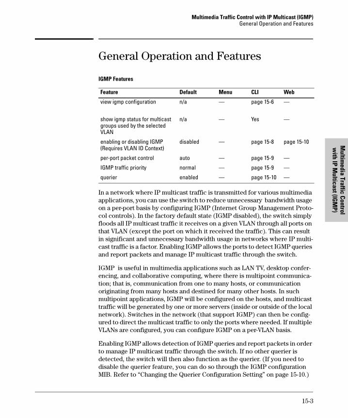
Multimedia Traffic Control with IP Multicast (IGMP)General Operation and Features
Multim
edia Traffic Control w
ith IP Multicast (IG
MP)
General Operation and Features
IGMP Features
In a network where IP multicast traffic is transmitted for various multimedia applications, you can use the switch to reduce unnecessary bandwidth usage on a per-port basis by configuring IGMP (Internet Group Management Proto-col controls). In the factory default state (IGMP disabled), the switch simply floods all IP multicast traffic it receives on a given VLAN through all ports on that VLAN (except the port on which it received the traffic). This can result in significant and unnecessary bandwidth usage in networks where IP multi-cast traffic is a factor. Enabling IGMP allows the ports to detect IGMP queries and report packets and manage IP multicast traffic through the switch.
IGMP is useful in multimedia applications such as LAN TV, desktop confer-encing, and collaborative computing, where there is multipoint communica-tion; that is, communication from one to many hosts, or communication originating from many hosts and destined for many other hosts. In such multipoint applications, IGMP will be configured on the hosts, and multicast traffic will be generated by one or more servers (inside or outside of the local network). Switches in the network (that support IGMP) can then be config-ured to direct the multicast traffic to only the ports where needed. If multiple VLANs are configured, you can configure IGMP on a per-VLAN basis.
Enabling IGMP allows detection of IGMP queries and report packets in order to manage IP multicast traffic through the switch. If no other querier is detected, the switch will then also function as the querier. (If you need to disable the querier feature, you can do so through the IGMP configuration MIB. Refer to “Changing the Querier Configuration Setting” on page 15-10.)
Feature Default Menu CLI Web
view igmp configuration n/a — page 15-6 —
show igmp status for multicast groups used by the selected VLAN
n/a — Yes —
enabling or disabling IGMP(Requires VLAN ID Context)
disabled — page 15-8 page 15-10
per-port packet control auto — page 15-9 —
IGMP traffic priority normal — page 15-9 —
querier enabled — page 15-10 —
15-3
Multimedia Traffic Control with IP Multicast (IGMP) General Operation and Features
Mul
timed
ia T
raffi
c Co
ntro
l w
ith IP
Mul
ticas
t (IG
MP)
N o t e IGMP configuration on the Switch 4108GL operates at the VLAN context level. If you are not using VLANs, then configure IGMP in VLAN 1 (the default VLAN) context.
IGMP Terms
� IGMP Device: A switch or router running IGMP traffic control features.
� IGMP Host: An end-node device running an IGMP (multipoint, or multicast communication) application.
� Querier: A required IGMP device that facilitates the IGMP protocol and traffic flow on a given LAN. This device tracks which ports are connected to devices (IGMP clients) that belong to specific multicast groups, and triggers updates of this information. A querier uses data received from the queries to determine whether to forward or block multicast traffic on specific ports. When the switch has an IP address on a given VLAN, it automatically operates as a Querier for that VLAN if it does not detect a multicast router or another switch functioning as a Querier. When enabled (the default state), the switch’s querier function eliminates the need for a multicast router. In most cases, HP recommends that you leave this parameter in the default “enabled” state even if you have a multicast router performing the querier function in your multicast group. For more information, see “How IGMP Operates” on page 15-11.
15-4
Multimedia Traffic Control with IP Multicast (IGMP)General Operation and Features
Multim
edia Traffic Control w
ith IP Multicast (IG
MP)
IGMP Operating Features
Basic Operation
In the factory default configuration, IGMP is disabled. If multiple VLANs are not configured, you must configure IGMP on the default VLAN (DEFAULT_VLAN; VID = 1). If multiple VLANs are configured, you must configure IGMP on a per-VLAN basis for every VLAN where this feature is desired.
Enhancements
With the CLI, you can configure these additional options:
� Forward with High Priority. Disabling this parameter (the default) causes the switch or VLAN to process IP multicast traffic, along with other traffic, in the order received (usually, normal priority). Enabling this parameter causes the switch or VLAN to give a higher priority to IP multicast traffic than to other traffic.
� Auto/Blocked/Forward: You can use the console to configure individual ports to any of the following states:
• Auto (the default): Causes the switch to interpret IGMP packets and to filter IP multicast traffic based on the IGMP packet information for ports belonging to a multicast group. This means that IGMP traffic will be forwarded on a specific port only if an IGMP host or multicast router is connected to the port.
• Blocked: Causes the switch to drop all IGMP transmissions received from a specific port and to block all outgoing IP Multicast packets for that port. This has the effect of preventing IGMP traffic from moving through specific ports.
• Forward: Causes the switch to forward all IGMP and IP multicast transmissions through the port.
� Operation With or Without IP Addressing: This feature helps to conserve IP addresses by enabling IGMP to run on VLANs that do not have an IP address. See “Operation With or Without IP Addressing” on page 15-12.
� Fast-Leave IGMP: This automatic feature reduces leave delays, which helps to reduce unnecessary multicast traffic. See “Automatic Fast-Leave IGMP” on page 15-13.
� Forced Fast-Leave IGMP: Where a port is connected to multiple end nodes, this feature speeds up the process of blocking unnecessary IGMP traffic to the port.
15-5
Multimedia Traffic Control with IP Multicast (IGMP) CLI: Configuring and Displaying IGMP
Mul
timed
ia T
raffi
c Co
ntro
l w
ith IP
Mul
ticas
t (IG
MP)
� Querier Capability: The switch performs this function for IGMP on VLANs having an IP address when there is no other device in the VLAN acting as querier. See “Querier Operation” on page 15-18.
N o t e s Whenever IGMP is enabled, the switch generates an Event Log message indicating whether querier functionality is enabled.
IP multicast traffic groups are identified by IP addresses in the range of 224.0.0.0 to 239.255.255.255. Also, incoming IGMP packets intended for reserved, or “well-known” multicast addresses automatically flood through all ports (except the port on which the packets entered the switch). For more on this topic, see “The Switch Excludes Well-Known or Reserved Multicast Addresses from IP Multicast Filtering” on page 15-19.
For more information, refer to “How IGMP Operates” on page 15-11.
CLI: Configuring and Displaying IGMP
IGMP Commands Used in This Section
show ip igmp configuration page 15-7
ip igmp page 15-8
high-priority-forward page 15-9
auto <[ethernet] <port-list> page 15-9
blocked <[ethernet] <port-list> page 15-9
forward <[ethernet] <port-list> page 15-9
querier page 15-10
show ip igmp See “Internet Group Management Protocol (IGMP) Status” on page 17-19
15-6
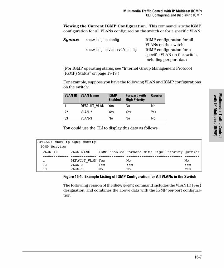
Multimedia Traffic Control with IP Multicast (IGMP)CLI: Configuring and Displaying IGMP
Multim
edia Traffic Control w
ith IP Multicast (IG
MP)
Viewing the Current IGMP Configuration. This command lists the IGMP configuration for all VLANs configured on the switch or for a specific VLAN.
Syntax: show ip igmp config IGMP configuration for allVLANs on the switch
show ip igmp vlan <vid> config IGMP configuration for a specific VLAN on the switch, including per-port data
(For IGMP operating status, see “Internet Group Management Protocol (IGMP) Status” on page 17-19.)
For example, suppose you have the following VLAN and IGMP configurations on the switch:
You could use the CLI to display this data as follows:
Figure 15-1. Example Listing of IGMP Configuration for All VLANs in the Switch
The following version of the show ip igmp command includes the VLAN ID (vid) designation, and combines the above data with the IGMP per-port configura-tion:
VLAN ID VLAN Name IGMP Enabled
Forward with High Priority
Querier
1 DEFAULT_VLAN Yes No No
22 VLAN-2 Yes Yes Yes
33 VLAN-3 No No No
15-7
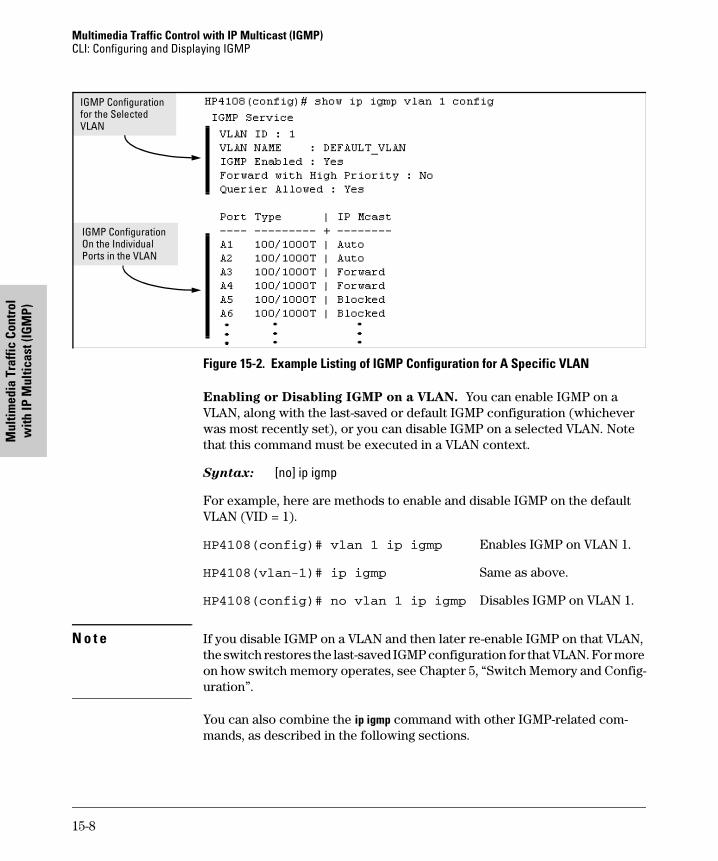
Multimedia Traffic Control with IP Multicast (IGMP) CLI: Configuring and Displaying IGMP
Mul
timed
ia T
raffi
c Co
ntro
l w
ith IP
Mul
ticas
t (IG
MP)
Figure 15-2. Example Listing of IGMP Configuration for A Specific VLAN
Enabling or Disabling IGMP on a VLAN. You can enable IGMP on a VLAN, along with the last-saved or default IGMP configuration (whichever was most recently set), or you can disable IGMP on a selected VLAN. Note that this command must be executed in a VLAN context.
Syntax: [no] ip igmp
For example, here are methods to enable and disable IGMP on the default VLAN (VID = 1).
HP4108(config)# vlan 1 ip igmp Enables IGMP on VLAN 1.
HP4108(vlan-1)# ip igmp Same as above.
HP4108(config)# no vlan 1 ip igmp Disables IGMP on VLAN 1.
N o t e If you disable IGMP on a VLAN and then later re-enable IGMP on that VLAN, the switch restores the last-saved IGMP configuration for that VLAN. For more on how switch memory operates, see Chapter 5, “Switch Memory and Config-uration”.
You can also combine the ip igmp command with other IGMP-related com-mands, as described in the following sections.
IGMP Configuration for the Selected VLAN
IGMP Configuration On the Individual Ports in the VLAN
15-8
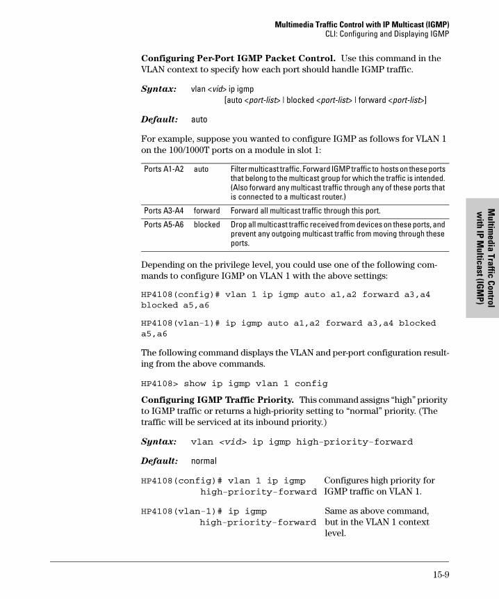
Multimedia Traffic Control with IP Multicast (IGMP)CLI: Configuring and Displaying IGMP
Multim
edia Traffic Control w
ith IP Multicast (IG
MP)
Configuring Per-Port IGMP Packet Control. Use this command in the VLAN context to specify how each port should handle IGMP traffic.
Syntax: vlan <vid> ip igmp [auto <port-list> | blocked <port-list> | forward <port-list>]
Default: auto
For example, suppose you wanted to configure IGMP as follows for VLAN 1 on the 100/1000T ports on a module in slot 1:
Depending on the privilege level, you could use one of the following com-mands to configure IGMP on VLAN 1 with the above settings:
HP4108(config)# vlan 1 ip igmp auto a1,a2 forward a3,a4
blocked a5,a6
HP4108(vlan-1)# ip igmp auto a1,a2 forward a3,a4 blocked
a5,a6
The following command displays the VLAN and per-port configuration result-ing from the above commands.
HP4108> show ip igmp vlan 1 config
Configuring IGMP Traffic Priority. This command assigns “high” priority to IGMP traffic or returns a high-priority setting to “normal” priority. (The traffic will be serviced at its inbound priority.)
Syntax: vlan <vid> ip igmp high-priority-forward
Default: normal
HP4108(config)# vlan 1 ip igmp Configures high priority forhigh-priority-forward IGMP traffic on VLAN 1.
HP4108(vlan-1)# ip igmp Same as above command,high-priority-forward but in the VLAN 1 context
level.
Ports A1-A2 auto Filter multicast traffic. Forward IGMP traffic to hosts on these ports that belong to the multicast group for which the traffic is intended. (Also forward any multicast traffic through any of these ports that is connected to a multicast router.)
Ports A3-A4 forward Forward all multicast traffic through this port.
Ports A5-A6 blocked Drop all multicast traffic received from devices on these ports, and prevent any outgoing multicast traffic from moving through these ports.
15-9
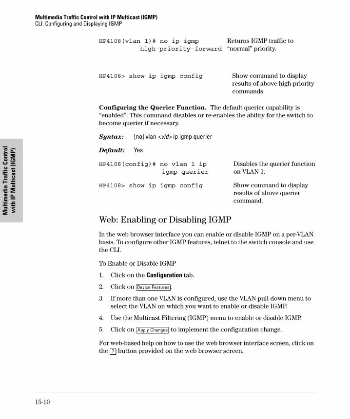
Multimedia Traffic Control with IP Multicast (IGMP) CLI: Configuring and Displaying IGMP
Mul
timed
ia T
raffi
c Co
ntro
l w
ith IP
Mul
ticas
t (IG
MP)
HP4108(vlan 1)# no ip igmp Returns IGMP traffic to high-priority-forward “normal” priority.
HP4108> show ip igmp config Show command to display results of above high-priority commands.
Configuring the Querier Function. The default querier capability is “enabled”. This command disables or re-enables the ability for the switch to become querier if necessary.
Syntax: [no] vlan <vid> ip igmp querier
Default: Yes
HP4108(config)# no vlan 1 ip Disables the querier functionigmp querier on VLAN 1.
HP4108> show ip igmp config Show command to displayresults of above querier command.
Web: Enabling or Disabling IGMP
In the web browser interface you can enable or disable IGMP on a per-VLAN basis. To configure other IGMP features, telnet to the switch console and use the CLI.
To Enable or Disable IGMP
1. Click on the Configuration tab.
2. Click on [Device Features].
3. If more than one VLAN is configured, use the VLAN pull-down menu to select the VLAN on which you want to enable or disable IGMP.
4. Use the Multicast Filtering (IGMP) menu to enable or disable IGMP.
5. Click on [Apply Changes] to implement the configuration change.
For web-based help on how to use the web browser interface screen, click on the [?] button provided on the web browser screen.
15-10
Multimedia Traffic Control with IP Multicast (IGMP)How IGMP Operates
Multim
edia Traffic Control w
ith IP Multicast (IG
MP)
How IGMP Operates
The Internet Group Management Protocol (IGMP) is an internal protocol of the Internet Protocol (IP) suite. IP manages multicast traffic by using switches, multicast routers, and hosts that support IGMP. (In Hewlett-Pack-ard’s implementation of IGMP, a multicast router is not necessary as long as a switch is configured to support IGMP with the querier feature enabled.) A set of hosts, routers, and/or switches that send or receive multicast data streams to or from the same source(s) is termed a multicast group, and all devices in the group use the same multicast group address. The multicast group running version 2 of IGMP uses three fundamental types of messages to communicate:
� Query: A message sent from the querier (multicast router or switch) asking for a response from each host belonging to the multicast group. If a multicast router supporting IGMP is not present, then the switch must assume this function in order to elicit group membership information from the hosts on the network. (If you need to disable the querier feature, you can do so through the CLI, using the IGMP configuration MIB. See “Changing the Querier Configuration Setting” on page “Configuring the Querier Function” on page 15-10.)
� Report (Join): A message sent by a host to the querier to indicate that the host wants to be or is a member of a given group indicated in the report message.
� Leave Group: A message sent by a host to the querier to indicate that the host has ceased to be a member of a specific multicast group.
An IP multicast packet includes the multicast group (address) to which the packet belongs. When an IGMP client connected to a switch port needs to receive multicast traffic from a specific group, it joins the group by sending an IGMP report (join request) to the network. (The multicast group specified in the join request is determined by the requesting application running on the IGMP client.) When a networking device with IGMP enabled receives the join request for a specific group, it forwards any IP multicast traffic it receives for that group through the port on which the join request was received. When the client is ready to leave the multicast group, it sends a Leave Group message to the network and ceases to be a group member. When the leave request is detected, the appropriate IGMP device will cease transmitting traffic for the designated multicast group through the port on which the leave request was received (as long as there are no other current members of that group on the affected port).
15-11
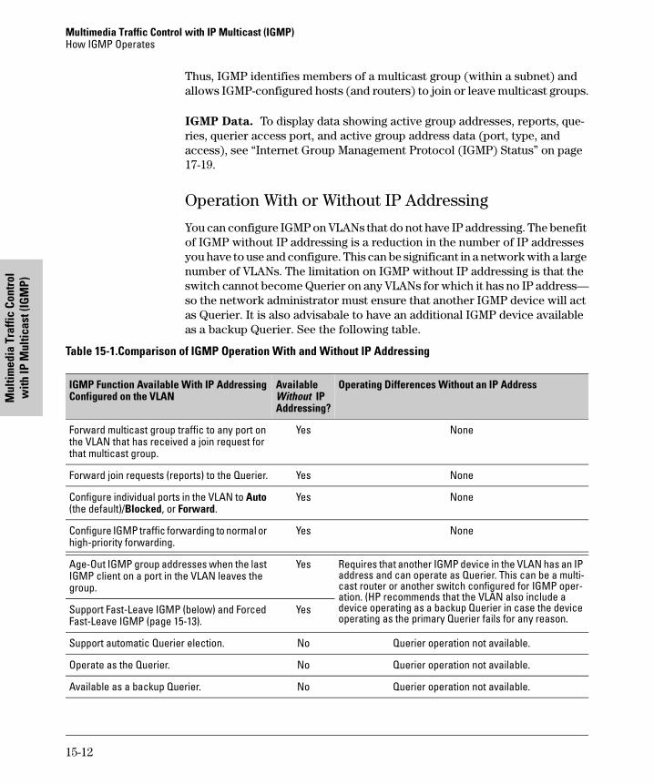
Multimedia Traffic Control with IP Multicast (IGMP) How IGMP Operates
Mul
timed
ia T
raffi
c Co
ntro
l w
ith IP
Mul
ticas
t (IG
MP)
Thus, IGMP identifies members of a multicast group (within a subnet) and allows IGMP-configured hosts (and routers) to join or leave multicast groups.
IGMP Data. To display data showing active group addresses, reports, que-ries, querier access port, and active group address data (port, type, and access), see “Internet Group Management Protocol (IGMP) Status” on page 17-19.
Operation With or Without IP Addressing
You can configure IGMP on VLANs that do not have IP addressing. The benefit of IGMP without IP addressing is a reduction in the number of IP addresses you have to use and configure. This can be significant in a network with a large number of VLANs. The limitation on IGMP without IP addressing is that the switch cannot become Querier on any VLANs for which it has no IP address—so the network administrator must ensure that another IGMP device will act as Querier. It is also advisabale to have an additional IGMP device available as a backup Querier. See the following table.
Table 15-1.Comparison of IGMP Operation With and Without IP Addressing
IGMP Function Available With IP AddressingConfigured on the VLAN
Available Without IPAddressing?
Operating Differences Without an IP Address
Forward multicast group traffic to any port on the VLAN that has received a join request for that multicast group.
Yes None
Forward join requests (reports) to the Querier. Yes None
Configure individual ports in the VLAN to Auto (the default)/Blocked, or Forward.
Yes None
Configure IGMP traffic forwarding to normal or high-priority forwarding.
Yes None
Age-Out IGMP group addresses when the last IGMP client on a port in the VLAN leaves the group.
Yes Requires that another IGMP device in the VLAN has an IP address and can operate as Querier. This can be a multi-cast router or another switch configured for IGMP oper-ation. (HP recommends that the VLAN also include a device operating as a backup Querier in case the device operating as the primary Querier fails for any reason.
Support Fast-Leave IGMP (below) and Forced Fast-Leave IGMP (page 15-13).
Yes
Support automatic Querier election. No Querier operation not available.
Operate as the Querier. No Querier operation not available.
Available as a backup Querier. No Querier operation not available.
15-12
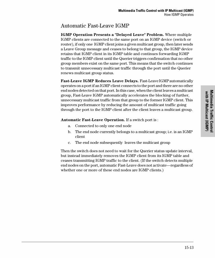
Multimedia Traffic Control with IP Multicast (IGMP)How IGMP Operates
Multim
edia Traffic Control w
ith IP Multicast (IG
MP)
Automatic Fast-Leave IGMP
IGMP Operation Presents a "Delayed Leave" Problem. Where multiple IGMP clients are connected to the same port on an IGMP device (switch or router), if only one IGMP client joins a given multicast group, then later sends a Leave Group message and ceases to belong to that group, the IGMP device retains that IGMP client in its IGMP table and continues forwarding IGMP traffic to the IGMP client until the Querier triggers confirmation that no other group members exist on the same port. This means that the switch continues to transmit unnecessary multicast traffic through the port until the Querier renews multicast group status.
Fast-Leave IGMP Reduces Leave Delays. Fast-Leave IGMP automatically operates on a port if an IGMP client connects to the port and there are no other end nodes detected on that port. In this case, when the client leaves a multicast group, Fast-Leave IGMP automatically accelerates the blocking of further, unnecessary multicast traffic from that group to the former IGMP client. This improves performance by reducing the amount of multicast traffic going through the port to the IGMP client after the client leaves a multicast group.
Automatic Fast-Leave Operation. If a switch port is :
a. Connected to only one end node
b. The end node currently belongs to a multicast group; i.e. is an IGMP client
c. The end node subsequently leaves the multicast group
Then the switch does not need to wait for the Querier status update interval, but instead immediately removes the IGMP client from its IGMP table and ceases transmitting IGMP traffic to the client. (If the switch detects multiple end nodes on the port, automatic Fast-Leave does not activate—regardless of whether one or more of these end nodes are IGMP clients.)
15-13
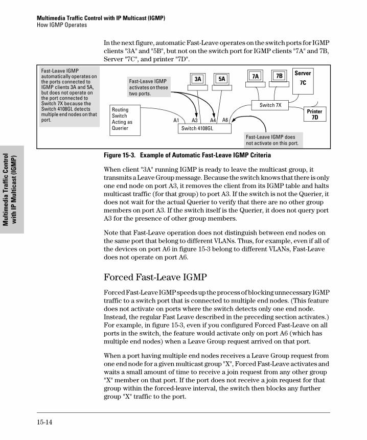
Multimedia Traffic Control with IP Multicast (IGMP) How IGMP Operates
Mul
timed
ia T
raffi
c Co
ntro
l w
ith IP
Mul
ticas
t (IG
MP)
In the next figure, automatic Fast-Leave operates on the switch ports for IGMP clients "3A" and "5B", but not on the switch port for IGMP clients "7A" and 7B, Server "7C", and printer "7D".
Figure 15-3. Example of Automatic Fast-Leave IGMP Criteria
When client "3A" running IGMP is ready to leave the multicast group, it transmits a Leave Group message. Because the switch knows that there is only one end node on port A3, it removes the client from its IGMP table and halts multicast traffic (for that group) to port A3. If the switch is not the Querier, it does not wait for the actual Querier to verify that there are no other group members on port A3. If the switch itself is the Querier, it does not query port A3 for the presence of other group members.
Note that Fast-Leave operation does not distinguish between end nodes on the same port that belong to different VLANs. Thus, for example, even if all of the devices on port A6 in figure 15-3 belong to different VLANs, Fast-Leave does not operate on port A6.
Forced Fast-Leave IGMP
Forced Fast-Leave IGMP speeds up the process of blocking unnecessary IGMP traffic to a switch port that is connected to multiple end nodes. (This feature does not activate on ports where the switch detects only one end node. Instead, the regular Fast Leave described in the preceding section activates.) For example, in figure 15-3, even if you configured Forced Fast-Leave on all ports in the switch, the feature would activate only on port A6 (which has multiple end nodes) when a Leave Group request arrived on that port.
When a port having multiple end nodes receives a Leave Group request from one end node for a given multicast group "X", Forced Fast-Leave activates and waits a small amount of time to receive a join request from any other group "X" member on that port. If the port does not receive a join request for that group within the forced-leave interval, the switch then blocks any further group "X" traffic to the port.
Routing Switch Acting as Querier Switch 4108GL
Server
7C
Switch 7X
3A
5A 7A
Fast-Leave IGMP automatically operates on the ports connected to IGMP clients 3A and 5A, but does not operate on the port connected to Switch 7X because the Switch 4108GL detects multiple end nodes on that port.
Fast-Leave IGMP does not activate on this port.
Fast-Leave IGMP activates on these two ports.
A1 A3 A4 A6
Printer 7D
7B
15-14
Multimedia Traffic Control with IP Multicast (IGMP)How IGMP Operates
Multim
edia Traffic Control w
ith IP Multicast (IG
MP)
Configuration Options for Forced Fast-Leave
N o t e o n V L A N N u m b e r s :
In the HP Procurve Switch 4108GL, the walkmib and setmib commands use an internal VLAN number (and not the VLAN ID, or VID) to display or change many per-vlan features, such as the Forced Fast-Leave state. Because the internal VLAN number for the default VLAN is always 1 (regardless of whether VLANs are enabled on the switch), and because a discussion of internal VLAN numbers for multiple VLANs is beyond the scope of this document, the discussion here concentrates on examples that use the default VLAN.
Listing the Forced Fast-Leave Configuration
The Forced Fast-Leave configuration data is available in the switch’s MIB (Management Information Base), and includes the state (enabled or disabled) for each port and the Forced-Leave Interval for all ports on the switch.
To List the Forced Fast-Leave State for all Ports in the Switch. Go to the switch’s command prompt and use the walkmib command, as shown below.
1. From the Main Menu, select:
5. Diagnostics . . .
4. Command Prompt
2. Do one of the following:
• If VLANs are not enabled on the switch, go to step 3.
• If VLANs are enabled on the switch:
i. You will be prompted to select a VLAN. For example:
ii. Because you can list the Forced Fast-Leave state for all ports on the switch from any VLAN, just press [Enter] to select the displayed VLAN.
3. Enter either of the following walkmib command options:
walkmib hpSwitchIgmpPortForcedLeaveState
Feature Default Settings Function
Forced Fast-Leave state
2 (disabled)
1 (enabled)2 (disabled)
Uses the setmib command to enable or disable Forced Fast-Leave on individual ports. When enabled on a port, Forced Fast-Leave operates only if the switch detects multiple end nodes (and at least one IGMP client) on that port.
15-15
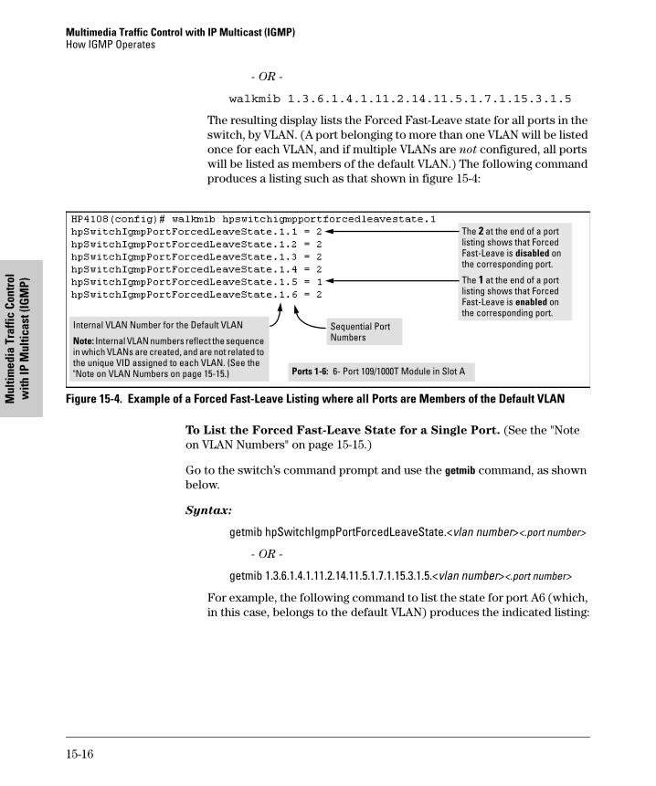
Multimedia Traffic Control with IP Multicast (IGMP) How IGMP Operates
Mul
timed
ia T
raffi
c Co
ntro
l w
ith IP
Mul
ticas
t (IG
MP)
- OR -
walkmib 1.3.6.1.4.1.11.2.14.11.5.1.7.1.15.3.1.5
The resulting display lists the Forced Fast-Leave state for all ports in the switch, by VLAN. (A port belonging to more than one VLAN will be listed once for each VLAN, and if multiple VLANs are not configured, all ports will be listed as members of the default VLAN.) The following command produces a listing such as that shown in figure 15-4:
Figure 15-4. Example of a Forced Fast-Leave Listing where all Ports are Members of the Default VLAN
To List the Forced Fast-Leave State for a Single Port. (See the "Note on VLAN Numbers" on page 15-15.)
Go to the switch’s command prompt and use the getmib command, as shown below.
Syntax:
getmib hpSwitchIgmpPortForcedLeaveState.<vlan number><.port number>
- OR -
getmib 1.3.6.1.4.1.11.2.14.11.5.1.7.1.15.3.1.5.<vlan number><.port number>
For example, the following command to list the state for port A6 (which, in this case, belongs to the default VLAN) produces the indicated listing:
The 2 at the end of a port listing shows that Forced Fast-Leave is disabled on the corresponding port.
The 1 at the end of a port listing shows that Forced Fast-Leave is enabled on the corresponding port.
Ports 1-6: 6- Port 109/1000T Module in Slot A
Internal VLAN Number for the Default VLAN
Note: Internal VLAN numbers reflect the sequence in which VLANs are created, and are not related to the unique VID assigned to each VLAN. (See the "Note on VLAN Numbers on page 15-15.)
Sequential PortNumbers
15-16
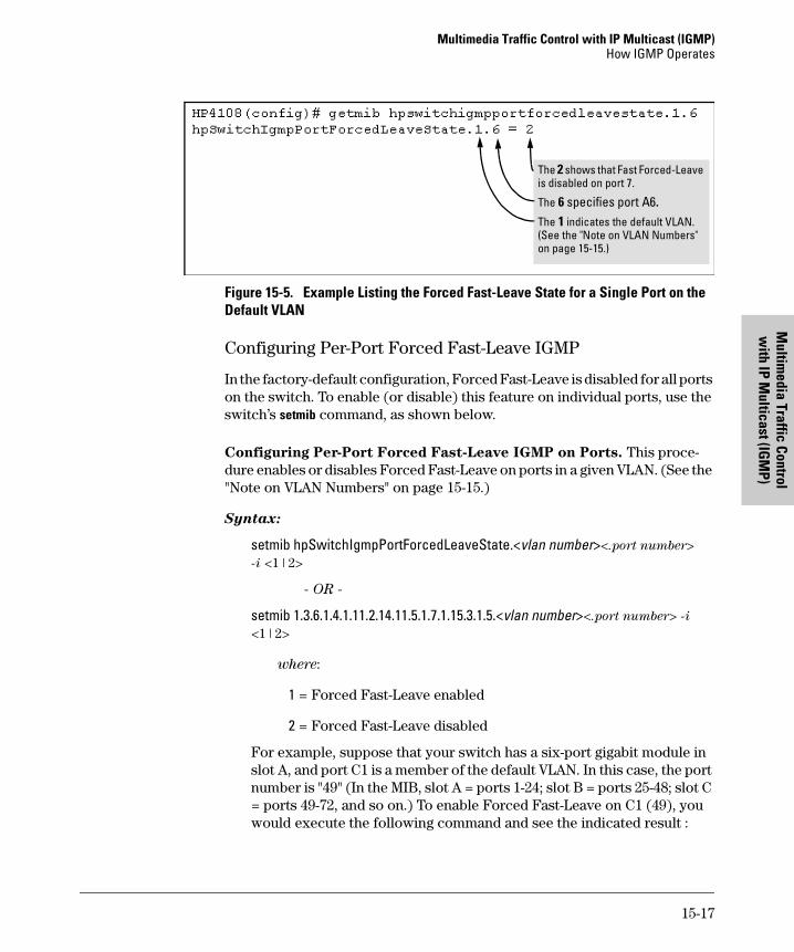
Multimedia Traffic Control with IP Multicast (IGMP)How IGMP Operates
Multim
edia Traffic Control w
ith IP Multicast (IG
MP)
Figure 15-5. Example Listing the Forced Fast-Leave State for a Single Port on the Default VLAN
Configuring Per-Port Forced Fast-Leave IGMP
In the factory-default configuration, Forced Fast-Leave is disabled for all ports on the switch. To enable (or disable) this feature on individual ports, use the switch’s setmib command, as shown below.
Configuring Per-Port Forced Fast-Leave IGMP on Ports. This proce-dure enables or disables Forced Fast-Leave on ports in a given VLAN. (See the "Note on VLAN Numbers" on page 15-15.)
Syntax:
setmib hpSwitchIgmpPortForcedLeaveState.<vlan number><.port number>
-i <1 | 2>
- OR -
setmib 1.3.6.1.4.1.11.2.14.11.5.1.7.1.15.3.1.5.<vlan number><.port number> -i
<1 | 2>
where:
1 = Forced Fast-Leave enabled
2 = Forced Fast-Leave disabled
For example, suppose that your switch has a six-port gigabit module in slot A, and port C1 is a member of the default VLAN. In this case, the port number is "49" (In the MIB, slot A = ports 1-24; slot B = ports 25-48; slot C = ports 49-72, and so on.) To enable Forced Fast-Leave on C1 (49), you would execute the following command and see the indicated result :
The 2 shows that Fast Forced-Leave is disabled on port 7.
The 6 specifies port A6.The 1 indicates the default VLAN. (See the "Note on VLAN Numbers" on page 15-15.)
15-17
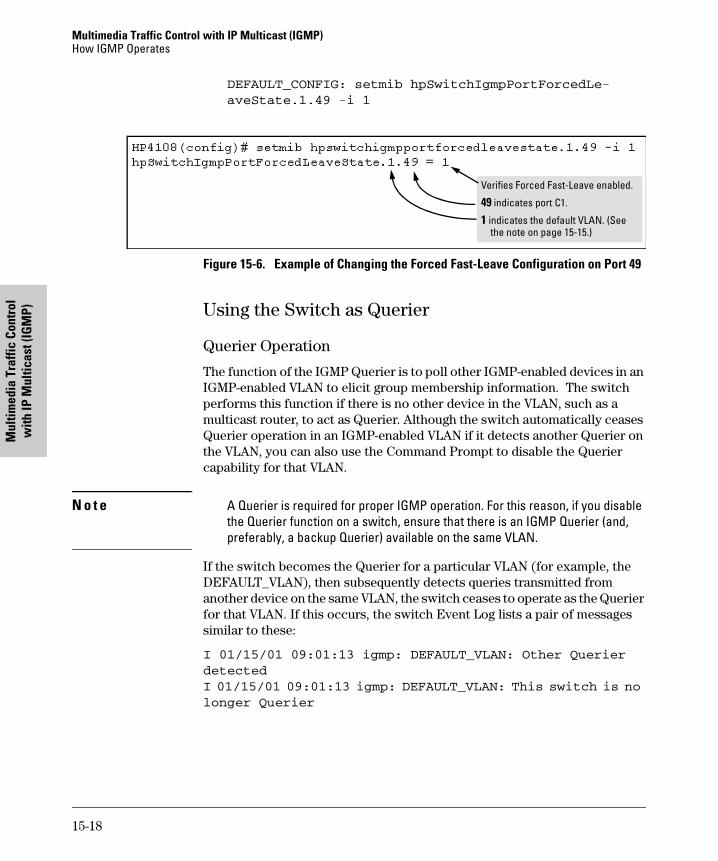
Multimedia Traffic Control with IP Multicast (IGMP) How IGMP Operates
Mul
timed
ia T
raffi
c Co
ntro
l w
ith IP
Mul
ticas
t (IG
MP)
DEFAULT_CONFIG: setmib hpSwitchIgmpPortForcedLe-
aveState.1.49 -i 1
Figure 15-6. Example of Changing the Forced Fast-Leave Configuration on Port 49
Using the Switch as Querier
Querier Operation
The function of the IGMP Querier is to poll other IGMP-enabled devices in an IGMP-enabled VLAN to elicit group membership information. The switch performs this function if there is no other device in the VLAN, such as a multicast router, to act as Querier. Although the switch automatically ceases Querier operation in an IGMP-enabled VLAN if it detects another Querier on the VLAN, you can also use the Command Prompt to disable the Querier capability for that VLAN.
N o t e A Querier is required for proper IGMP operation. For this reason, if you disable the Querier function on a switch, ensure that there is an IGMP Querier (and, preferably, a backup Querier) available on the same VLAN.
If the switch becomes the Querier for a particular VLAN (for example, the DEFAULT_VLAN), then subsequently detects queries transmitted from another device on the same VLAN, the switch ceases to operate as the Querier for that VLAN. If this occurs, the switch Event Log lists a pair of messages similar to these:
I 01/15/01 09:01:13 igmp: DEFAULT_VLAN: Other Querier
detected
I 01/15/01 09:01:13 igmp: DEFAULT_VLAN: This switch is no
longer Querier
Verifies Forced Fast-Leave enabled.
49 indicates port C1.
1 indicates the default VLAN. (See the note on page 15-15.)
15-18
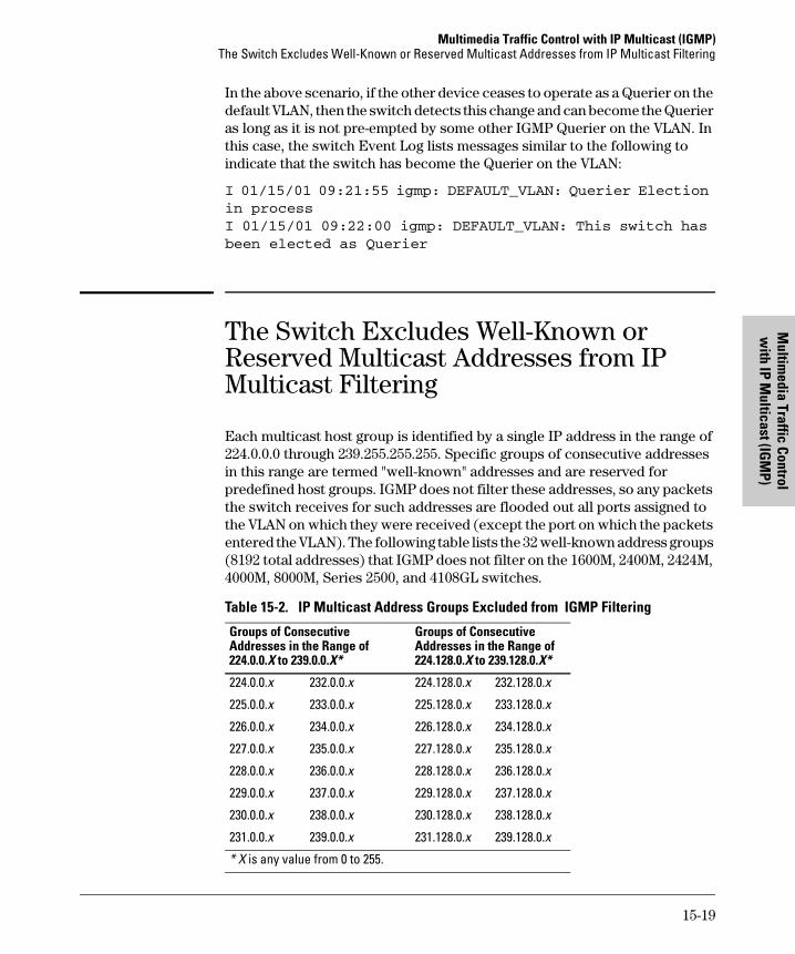
Multimedia Traffic Control with IP Multicast (IGMP)The Switch Excludes Well-Known or Reserved Multicast Addresses from IP Multicast Filtering
Multim
edia Traffic Control w
ith IP Multicast (IG
MP)
In the above scenario, if the other device ceases to operate as a Querier on the default VLAN, then the switch detects this change and can become the Querier as long as it is not pre-empted by some other IGMP Querier on the VLAN. In this case, the switch Event Log lists messages similar to the following to indicate that the switch has become the Querier on the VLAN:
I 01/15/01 09:21:55 igmp: DEFAULT_VLAN: Querier Election
in process
I 01/15/01 09:22:00 igmp: DEFAULT_VLAN: This switch has
been elected as Querier
The Switch Excludes Well-Known or Reserved Multicast Addresses from IP Multicast Filtering
Each multicast host group is identified by a single IP address in the range of 224.0.0.0 through 239.255.255.255. Specific groups of consecutive addresses in this range are termed "well-known" addresses and are reserved for predefined host groups. IGMP does not filter these addresses, so any packets the switch receives for such addresses are flooded out all ports assigned to the VLAN on which they were received (except the port on which the packets entered the VLAN). The following table lists the 32 well-known address groups (8192 total addresses) that IGMP does not filter on the 1600M, 2400M, 2424M, 4000M, 8000M, Series 2500, and 4108GL switches.
Table 15-2. IP Multicast Address Groups Excluded from IGMP Filtering
Groups of Consecutive Addresses in the Range of 224.0.0.X to 239.0.0.X*
Groups of Consecutive Addresses in the Range of 224.128.0.X to 239.128.0.X*
224.0.0.x 232.0.0.x 224.128.0.x 232.128.0.x
225.0.0.x 233.0.0.x 225.128.0.x 233.128.0.x
226.0.0.x 234.0.0.x 226.128.0.x 234.128.0.x
227.0.0.x 235.0.0.x 227.128.0.x 235.128.0.x
228.0.0.x 236.0.0.x 228.128.0.x 236.128.0.x
229.0.0.x 237.0.0.x 229.128.0.x 237.128.0.x
230.0.0.x 238.0.0.x 230.128.0.x 238.128.0.x
231.0.0.x 239.0.0.x 231.128.0.x 239.128.0.x
* X is any value from 0 to 255.
15-19
Multimedia Traffic Control with IP Multicast (IGMP) The Switch Excludes Well-Known or Reserved Multicast Addresses from IP Multicast Filtering
Mul
timed
ia T
raffi
c Co
ntro
l w
ith IP
Mul
ticas
t (IG
MP)
N o t e : IP Multicast Filters. IP multicast addresses occur in the range from 224.0.0.0 through 239.255.255.255 (which corresponds to the Ethernet multi-cast address range of 01005e-000000 through 01005e-7fffff). Where a switch has a static Traffic/Security filter configured with a “Multicast” filter type and a “Multicast Address” in this range, the switch will use the static filter unless IGMP learns of a multicast group destination in this range. In in this case, IGMP dynamically takes over the filtering function for the multicast destination address(es) for as long as the IGMP group is active. If the IGMP group subsequently deactivates, the switch returns filtering control to the static filter. This operation applies to the HP Procurve Switch 1600M, 2400M, 2424M, 4000M, and 8000M, but not to the Series 2500 switches and the Switch 4108GL (which do not have static traffic/security filters).
Reserved Addresses Excluded from IP Multicast (IGMP) Filtering.
Traffic to IP multicast groups in the IP address range of 224.0.0.0 to 224.0.0.255 will always be flooded because addresses in this range are “well known” or “reserved” addresses. Thus, if IP Multicast is enabled and there is an IP multicast group within the reserved address range, traffic to that group will be flooded instead of filtered by the switch.
Number of IP Multicast Addresses Allowed
Multicast filters and IGMP filters (addresses) together can total up to 255 in the switch. If multiple VLANs are configured, then each filter is counted once per VLAN in which it is used.
15-20
Spanning Tree Protocol (STP)
16
Spanning Tree Protocol (STP)
Chapter Contents
Overview . . . . . . . . . . . . . . . . . . . . . . . . . . . . . . . . . . . . . . . . . . . . . . . . . . . . . 16-2
Menu: Configuring STP . . . . . . . . . . . . . . . . . . . . . . . . . . . . . . . . . . . . . . . . . 16-4
CLI: Configuring STP . . . . . . . . . . . . . . . . . . . . . . . . . . . . . . . . . . . . . . . . . . . 16-5
Web: Enabling or Disabling STP . . . . . . . . . . . . . . . . . . . . . . . . . . . . . . . . . . 16-9
How STP Operates . . . . . . . . . . . . . . . . . . . . . . . . . . . . . . . . . . . . . . . . . . . . . 16-9
STP Fast Mode . . . . . . . . . . . . . . . . . . . . . . . . . . . . . . . . . . . . . . . . . . . . 16-10
STP Operation with 802.1Q VLANs . . . . . . . . . . . . . . . . . . . . . . . . . . . 16-12
16-1
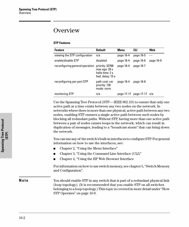
Spanning Tree Protocol (STP) Overview
Span
ning
Tre
e Pr
otoc
ol
(STP
)
Overview
STP Features
Use the Spanning Tree Protocol (STP— IEEE 802.1D) to ensure that only one active path at a time exists between any two nodes on the network. In networks where there is more than one physical, active path between any two nodes, enabling STP ensures a single active path between such nodes by blocking all redundant paths. Without STP, having more than one active path between a pair of nodes causes loops in the network, which can result in duplication of messages, leading to a “broadcast storm” that can bring down the network.
You can use any of the switch’s built-in interfaces to configure STP. For general information on how to use the interfaces, see:
� Chapter 2, “Using the Menu Interface”
� Chapter 3, “Using the Command Line Interface (CLI)”
� Chapter 4, “Using the HP Web Browser Interface
For information on how to use switch memory, see chapter 5, “Switch Memory and Configuration”.
N o t e You should enable STP in any switch that is part of a redundant physical link (loop topology). (It is recommended that you enable STP on all switches belonging to a loop topology.) This topic is covered in more detail under “How STP Operates” on page 16-9.
Feature Default Menu CLI Web
viewing the STP configuration n/a page 16-4 page 16-5 —
enable/disable STP disabled page 16-4 page 16-6 page 16-9
reconfiguring general operation priority: 32768max age: 20 shello time: 2 sfwd. delay: 15 s
page 16-4 page 16-7
reconfiguring per-port STP path cost: varpriority: 128mode: norm
page 16-4 page 16-8
monitoring STP n/a page 17-17 page 17-17 n/a
16-2
Spanning Tree Protocol (STP)Overview
Spanning Tree Protocol (STP)
As recommended in the IEEE 802.1Q VLAN standard, the Switch 4108GL uses single-instance STP. (As a result, the switch generates untagged Bridge Protocol Data Units—BPDUs.) This implementation creates a single spanning tree to make sure there are no network loops associated with any of the connections to the switch, regardless of whether multiple VLANs are config-ured on the switch. Thus, these switches do not distinguish between VLANs when identifying redundant physical links. If VLANs are configured on the switch, see “STP Operation with 802.1Q VLANs” on page 16-12.
STP Fast Mode for Overcoming Server Access Failures. If an end node is configured to automatically access a server, the duration of the STP startup sequence can result in a “server access failure”. On ports where this is a problem, configuring STP Fast Mode can eliminate the failure. For more information, see “STP Fast Mode” on page 16-10. The next sections describe how to configure STP on the switch. For more information on STP operation, see “How STP Operates” on page 16-9.
In the factory default configuration, STP is off. If a redundant link (loop) exists between nodes in your network, you should enable Spanning Tree.
N o t e STP retains its current parameter settings when disabled. Thus, if you disable STP, then later re-enable it, the parameter settings will be the same as before STP was disabled.
C a u t i o n Because the switch automatically gives faster links a higher priority, the default STP parameter settings are usually adequate for spanning tree operation. Also because incorrect STP settings can adversely affect network performance, you should not make changes unless you have a strong under-standing of how STP operates. For more on STP, see the IEEE 802.1D standard.
16-3
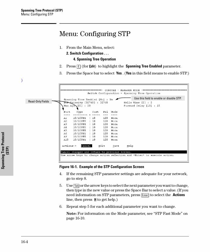
Spanning Tree Protocol (STP) Menu: Configuring STP
Span
ning
Tre
e Pr
otoc
ol
(STP
)
Menu: Configuring STP
1. From the Main Menu, select:
2. Switch Configuration . . .4. Spanning Tree Operation
2. Press [E] (for Edit) to highlight the Spanning Tree Enabled parameter.
3. Press the Space bar to select Yes . (Yes in this field means to enable STP.)
)
Figure 16-1. Example of the STP Configuration Screen
4. If the remaining STP parameter settings are adequate for your network, go to step 8.
5. Use [Tab] or the arrow keys to select the next parameter you want to change, then type in the new value or press the Space Bar to select a value. (If you need information on STP parameters, press [Enter] to select the Actions line, then press H to get help.)
6. Repeat step 5 for each additional parameter you want to change.
Note: For information on the Mode parameter, see “STP Fast Mode” on page 16-10.
Read-Only FieldsUse this field to enable or disable STP.
16-4
Spanning Tree Protocol (STP)CLI: Configuring STP
Spanning Tree Protocol (STP)
7. When you are finished editing parameters, press [Enter] to return to the Actions line.
8. Press [S] to save the currently displayed STP parameter settings, then return to the Main Menu.
CLI: Configuring STPSTP Commands Used in This Section
Viewing the Current STP Configuration. Regardless of whether STP is disabled (the default), this command lists the switch’s full STP configuration, including general settings and port settings.
Syntax: show spanning-tree configuration
In the default configuration, STP appears similar to the following:
show spanning-tree config Below
spanning-tree page 16-6
forward-delay <4 - 30> page 16-7
hello-time <1 - 10> page 16-7
maximum-age <6 - 40> page 16-7
priority <0 - 65535> page 16-7
ethernet <port-list> page 16-8
path-cost <1 - 65535> page 16-8
priority <0 - 255> page 16-8
mode <norm | fast> page 16-8
show spanning tree This command lists additional STP monitoring data not covered in this chapter. See “Spanning Tree Protocol (STP) Information” on page 17-17
16-5
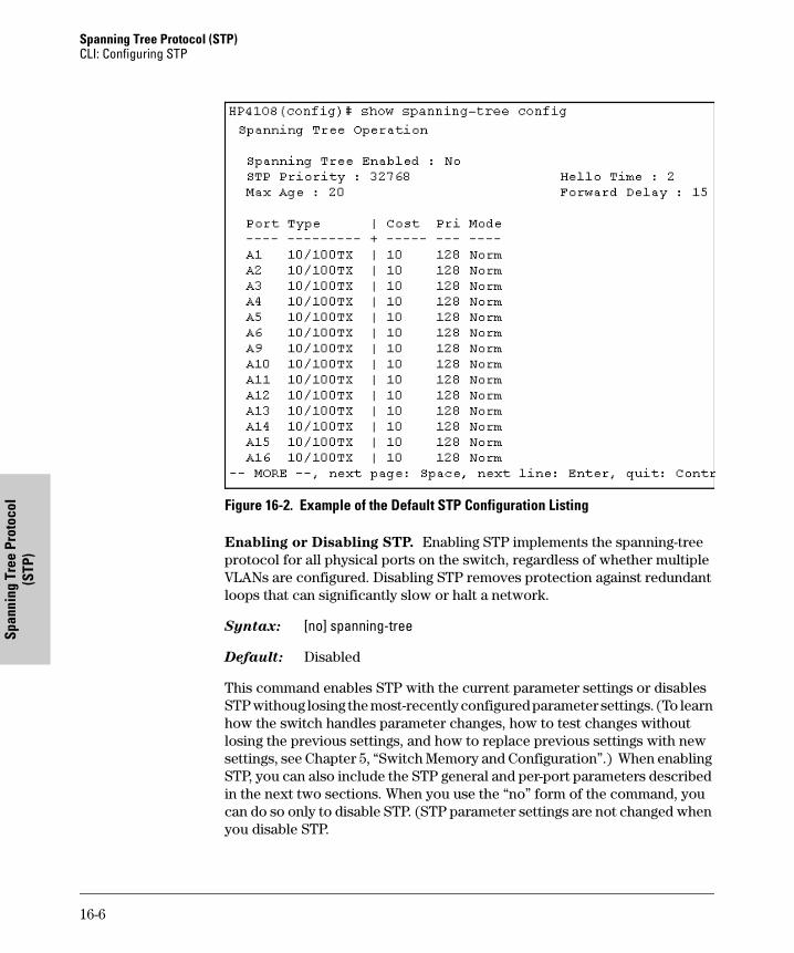
Spanning Tree Protocol (STP) CLI: Configuring STP
Span
ning
Tre
e Pr
otoc
ol
(STP
)
Figure 16-2. Example of the Default STP Configuration Listing
Enabling or Disabling STP. Enabling STP implements the spanning-tree protocol for all physical ports on the switch, regardless of whether multiple VLANs are configured. Disabling STP removes protection against redundant loops that can significantly slow or halt a network.
Syntax: [no] spanning-tree
Default: Disabled
This command enables STP with the current parameter settings or disables STP withoug losing the most-recently configured parameter settings. (To learn how the switch handles parameter changes, how to test changes without losing the previous settings, and how to replace previous settings with new settings, see Chapter 5, “Switch Memory and Configuration”.) When enabling STP, you can also include the STP general and per-port parameters described in the next two sections. When you use the “no” form of the command, you can do so only to disable STP. (STP parameter settings are not changed when you disable STP.
16-6
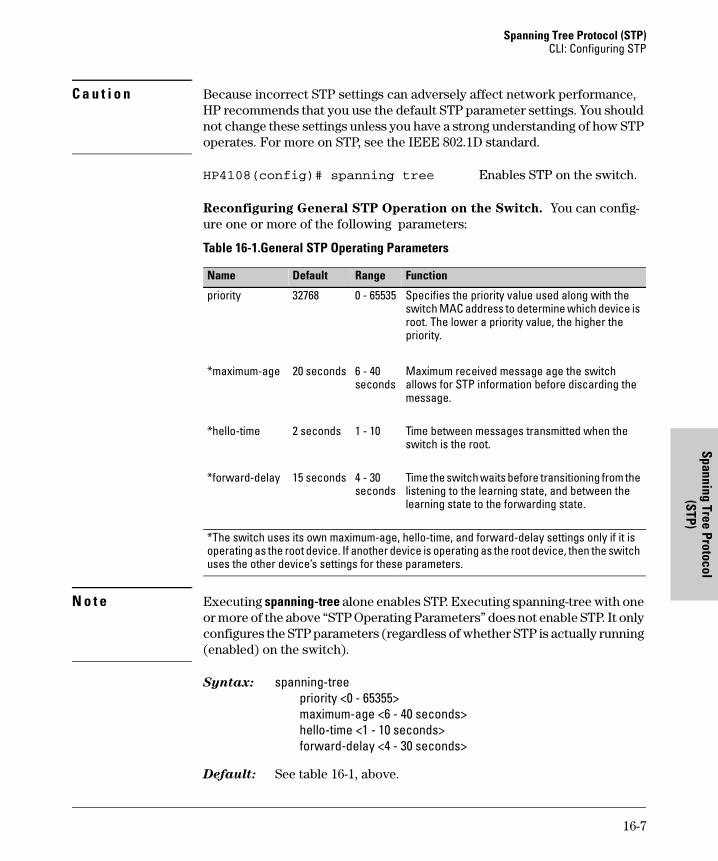
Spanning Tree Protocol (STP)CLI: Configuring STP
Spanning Tree Protocol (STP)
C a u t i o n Because incorrect STP settings can adversely affect network performance, HP recommends that you use the default STP parameter settings. You should not change these settings unless you have a strong understanding of how STP operates. For more on STP, see the IEEE 802.1D standard.
HP4108(config)# spanning tree Enables STP on the switch.
Reconfiguring General STP Operation on the Switch. You can config-ure one or more of the following parameters:
Table 16-1.General STP Operating Parameters
N o t e Executing spanning-tree alone enables STP. Executing spanning-tree with one or more of the above “STP Operating Parameters” does not enable STP. It only configures the STP parameters (regardless of whether STP is actually running (enabled) on the switch).
Syntax: spanning-treepriority <0 - 65355>maximum-age <6 - 40 seconds>hello-time <1 - 10 seconds>forward-delay <4 - 30 seconds>
Default: See table 16-1, above.
Name Default Range Function
priority 32768 0 - 65535 Specifies the priority value used along with the switch MAC address to determine which device is root. The lower a priority value, the higher the priority.
*maximum-age 20 seconds 6 - 40 seconds
Maximum received message age the switch allows for STP information before discarding the message.
*hello-time 2 seconds 1 - 10 Time between messages transmitted when the switch is the root.
*forward-delay 15 seconds 4 - 30 seconds
Time the switch waits before transitioning from the listening to the learning state, and between the learning state to the forwarding state.
*The switch uses its own maximum-age, hello-time, and forward-delay settings only if it is operating as the root device. If another device is operating as the root device, then the switch uses the other device’s settings for these parameters.
16-7
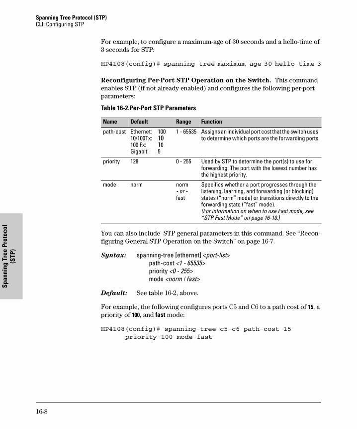
Spanning Tree Protocol (STP) CLI: Configuring STP
Span
ning
Tre
e Pr
otoc
ol
(STP
)
For example, to configure a maximum-age of 30 seconds and a hello-time of 3 seconds for STP:
HP4108(config)# spanning-tree maximum-age 30 hello-time 3
Reconfiguring Per-Port STP Operation on the Switch. This command enables STP (if not already enabled) and configures the following per-port parameters:
Table 16-2.Per-Port STP Parameters
You can also include STP general parameters in this command. See “Recon-figuring General STP Operation on the Switch” on page 16-7.
Syntax: spanning-tree [ethernet] <port-list>path-cost <1 - 65535>priority <0 - 255>mode <norm | fast>
Default: See table 16-2, above.
For example, the following configures ports C5 and C6 to a path cost of 15, a priority of 100, and fast mode:
HP4108(config)# spanning-tree c5-c6 path-cost 15
priority 100 mode fast
Name Default Range Function
path-cost Ethernet: 10010/100Tx: 10100 Fx: 10Gigabit: 5
1 - 65535 Assigns an individual port cost that the switch uses to determine which ports are the forwarding ports.
priority 128 0 - 255 Used by STP to determine the port(s) to use for forwarding. The port with the lowest number has the highest priority.
mode norm norm- or -fast
Specifies whether a port progresses through the listening, learning, and forwarding (or blocking) states (“norm” mode) or transitions directly to the forwarding state (“fast” mode). (For information on when to use Fast mode, see “STP Fast Mode” on page 16-10.)
16-8
Spanning Tree Protocol (STP)Web: Enabling or Disabling STP
Spanning Tree Protocol (STP)
Web: Enabling or Disabling STP
In the web browser interface you can enable or disable STP on the switch. To configure other STP features, telnet to the switch console and use the CLI.
To enable or disable STP on the switch:
1. Click on the Configuration tab
2. Click on [Device Features].
3. Enable or disable STP.
4. Click on [Apply Changes] to implement the configuration change.
For web-based help on how to use the web browser interface screen, click on the [?] button provided on the web browser screen.
How STP Operates
The switch automatically senses port identity and type, and automatically defines port cost and priority for each type. The console interface allows you to adjust the Cost and Priority for each port, as well as the Mode for each port and the global STP parameter values for the switch.
While allowing only one active path through a network at any time, STP retains any redundant physical path to serve as a backup (blocked) path in case the existing active path fails. Thus, if an active path fails, STP automatically activates (unblocks) an available backup to serve as the new active path for as long as the original active path is down. For example:
16-9
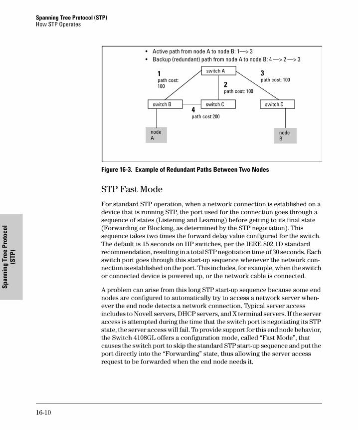
Spanning Tree Protocol (STP) How STP Operates
Span
ning
Tre
e Pr
otoc
ol
(STP
)
Figure 16-3. Example of Redundant Paths Between Two Nodes
STP Fast Mode
For standard STP operation, when a network connection is established on a device that is running STP, the port used for the connection goes through a sequence of states (Listening and Learning) before getting to its final state (Forwarding or Blocking, as determined by the STP negotiation). This sequence takes two times the forward delay value configured for the switch. The default is 15 seconds on HP switches, per the IEEE 802.1D standard recommendation, resulting in a total STP negotiation time of 30 seconds. Each switch port goes through this start-up sequence whenever the network con-nection is established on the port. This includes, for example, when the switch or connected device is powered up, or the network cable is connected.
A problem can arise from this long STP start-up sequence because some end nodes are configured to automatically try to access a network server when-ever the end node detects a network connection. Typical server access includes to Novell servers, DHCP servers, and X terminal servers. If the server access is attempted during the time that the switch port is negotiating its STP state, the server access will fail. To provide support for this end node behavior, the Switch 4108GL offers a configuration mode, called “Fast Mode”, that causes the switch port to skip the standard STP start-up sequence and put the port directly into the “Forwarding” state, thus allowing the server access request to be forwarded when the end node needs it.
nodeA
switch A
nodeB
switch Dswitch B switch C
1path cost: 100
3path cost: 100
4path cost:200
• Active path from node A to node B: 1—> 3• Backup (redundant) path from node A to node B: 4 —> 2 —> 3
2path cost: 100
16-10
Spanning Tree Protocol (STP)How STP Operates
Spanning Tree Protocol (STP)
If you encounter end nodes that repeatedly indicate server access failure when attempting to bring up their network connection, and you have enabled STP on the switch, try changing the configuration of the switch ports associated with those end nodes to STP Fast Mode.
C a u t i o n The Fast Mode configuration should be used only on switch ports connected to end nodes. Changing the Mode to Fast on ports connected to hubs, switches, or routers may cause loops in your network that STP may not be able to immediately detect, in all cases. This will cause temporary loops in your network. After the fast start-up sequence, though, the switch ports operate according to the STP standard, and will adjust their state to eliminate continu-ing network loops.
To Enable or Disable Fast Mode for a Switch Port:
You can use either the CLI or the menu interface to toggle between STP Fast mode and STP Normal mode. (To use the menu interface, see “Menu: Config-uring STP” on page 16-4.)
Syntax: spanning-tree <port list> mode <fast | norm>
For example, to configure Fast mode for ports C1-C3 and C5:
HP4108(config)# spanning-tree c1-c3,c5 mode fast
16-11
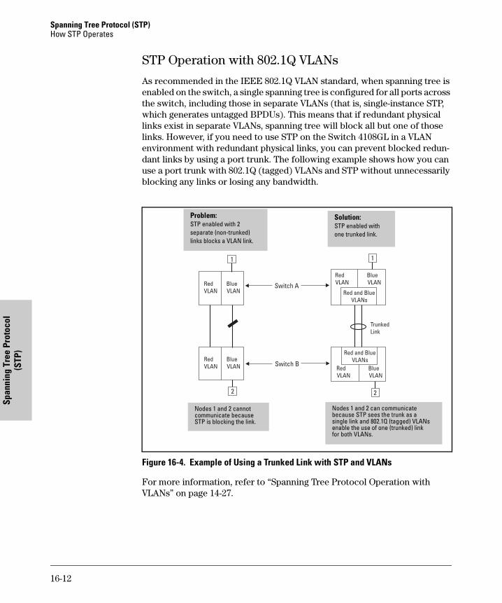
Spanning Tree Protocol (STP) How STP Operates
Span
ning
Tre
e Pr
otoc
ol
(STP
)
STP Operation with 802.1Q VLANs
As recommended in the IEEE 802.1Q VLAN standard, when spanning tree is enabled on the switch, a single spanning tree is configured for all ports across the switch, including those in separate VLANs (that is, single-instance STP, which generates untagged BPDUs). This means that if redundant physical links exist in separate VLANs, spanning tree will block all but one of those links. However, if you need to use STP on the Switch 4108GL in a VLAN environment with redundant physical links, you can prevent blocked redun-dant links by using a port trunk. The following example shows how you can use a port trunk with 802.1Q (tagged) VLANs and STP without unnecessarily blocking any links or losing any bandwidth.
Figure 16-4. Example of Using a Trunked Link with STP and VLANs
For more information, refer to “Spanning Tree Protocol Operation with VLANs” on page 14-27.
Problem:STP enabled with 2separate (non-trunked)links blocks a VLAN link.
Solution:STP enabled with one trunked link.
Nodes 1 and 2 cannotcommunicate becauseSTP is blocking the link.
Nodes 1 and 2 can communicatebecause STP sees the trunk as asingle link and 802.1Q (tagged) VLANsenable the use of one (trunked) linkfor both VLANs.
16-12

Spanning Tree Protocol (STP)How STP Operates
Spanning Tree Protocol (STP)
16-13

Spanning Tree Protocol (STP) How STP Operates
Span
ning
Tre
e Pr
otoc
ol
(STP
)
16-14
Monitoring and A
nalyzing Sw
itch Operation
17
Monitoring and Analyzing Switch Operation
ContentsOverview . . . . . . . . . . . . . . . . . . . . . . . . . . . . . . . . . . . . . . . . . . . . . . . . . . . . . 17-2
Status and Counters Data . . . . . . . . . . . . . . . . . . . . . . . . . . . . . . . . . . . . . . . 17- 3
Menu Access To Status and Counters . . . . . . . . . . . . . . . . . . . . . . . . . 17-4
General System Information . . . . . . . . . . . . . . . . . . . . . . . . . . . . . . . . . 17-5
Switch Management Address Information . . . . . . . . . . . . . . . . . . . . . . 17-6
Module Information . . . . . . . . . . . . . . . . . . . . . . . . . . . . . . . . . . . . . . . . 17-7
Port Status . . . . . . . . . . . . . . . . . . . . . . . . . . . . . . . . . . . . . . . . . . . . . . . . 17-8
Viewing Port and Trunk Group Statistics and Flow Control Status . 17-9
Viewing the Switch’s MAC Address Tables . . . . . . . . . . . . . . . . . . . . 17-12
Spanning Tree Protocol (STP) Information . . . . . . . . . . . . . . . . . . . . 17-17
Internet Group Management Protocol (IGMP) Status . . . . . . . . . . . 17-19
VLAN Information . . . . . . . . . . . . . . . . . . . . . . . . . . . . . . . . . . . . . . . . . 17-20
Web Browser Interface Status Information . . . . . . . . . . . . . . . . . . . . 17-22
Port Monitoring Features . . . . . . . . . . . . . . . . . . . . . . . . . . . . . . . . . . . . . . 17-23
Menu: Configuring Port Monitoring . . . . . . . . . . . . . . . . . . . . . . . . . . 17-24
CLI: Configuring Port Monitoring . . . . . . . . . . . . . . . . . . . . . . . . . . . . 17-25
Web: Configuring Port Monitoring . . . . . . . . . . . . . . . . . . . . . . . . . . . 17-27
17-1
Monitoring and Analyzing Switch OperationOverview
Mon
itori
ng a
nd A
naly
zing
Sw
itch
Ope
ratio
n
Overview
The Switch 4108GL has several built-in tools for monitoring, analyzing, and troubleshooting switch and network operation:
� Status: Includes options for displaying general switch information, man-agement address data, port status, port and trunk group statistics, MAC addresses detected on each port or VLAN, and STP, IGMP, and VLAN data (page 17-3).
� Counters: Display details of traffic volume on individual ports (page
17-9).
� Event Log: Lists switch operating events (“Using the Event Log To
Identify Problem Sources” on page 16).
� Alert Log: Lists network occurrences detected by the switch—in the Status | Overview screen of the web browser interface (page 4-20).
� Configurable trap receivers: Uses SNMP to enable management sta-tions on your network to receive SNMP traps from the switch (page 12-8).
� Port monitoring (mirroring): Copy all traffic from the specified ports to a designated monitoring port (page 17-23).
N o t e Link test and ping test—analysis tools in troubleshooting situations—are described in chapter 18, “Troubleshooting”. See page 18-17.
17-2
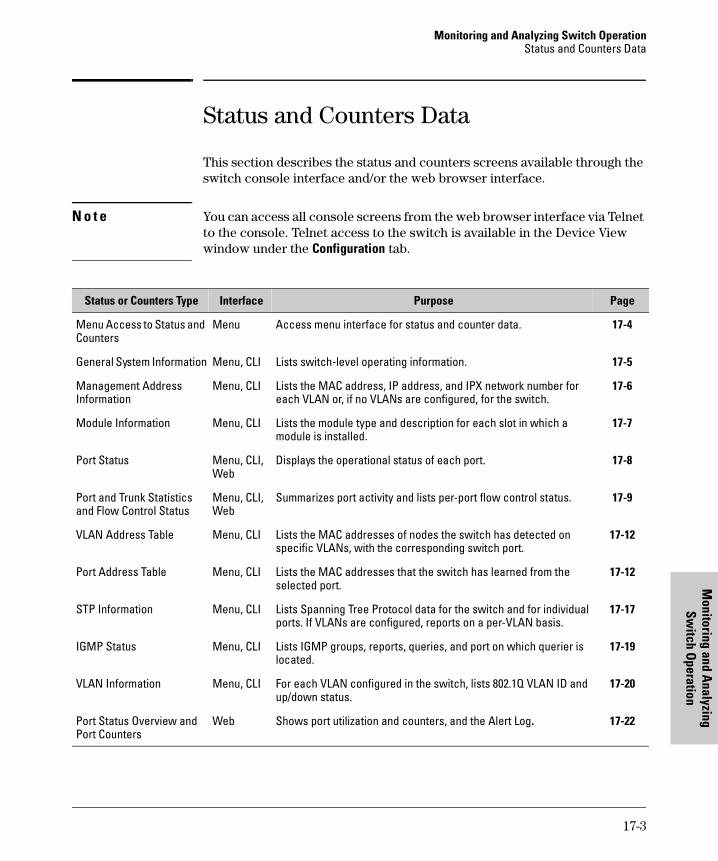
Monitoring and Analyzing Switch OperationStatus and Counters Data
Monitoring and A
nalyzing Sw
itch Operation
Status and Counters Data
This section describes the status and counters screens available through the switch console interface and/or the web browser interface.
N o t e You can access all console screens from the web browser interface via Telnet to the console. Telnet access to the switch is available in the Device View window under the Configuration tab.
Status or Counters Type Interface Purpose Page
Menu Access to Status and Counters
Menu Access menu interface for status and counter data. 17-4
General System Information Menu, CLI Lists switch-level operating information. 17-5
Management Address Information
Menu, CLI Lists the MAC address, IP address, and IPX network number for each VLAN or, if no VLANs are configured, for the switch.
17-6
Module Information Menu, CLI Lists the module type and description for each slot in which a module is installed.
17-7
Port Status Menu, CLI, Web
Displays the operational status of each port. 17-8
Port and Trunk Statistics and Flow Control Status
Menu, CLI, Web
Summarizes port activity and lists per-port flow control status. 17-9
VLAN Address Table Menu, CLI Lists the MAC addresses of nodes the switch has detected on specific VLANs, with the corresponding switch port.
17-12
Port Address Table Menu, CLI Lists the MAC addresses that the switch has learned from the selected port.
17-12
STP Information Menu, CLI Lists Spanning Tree Protocol data for the switch and for individual ports. If VLANs are configured, reports on a per-VLAN basis.
17-17
IGMP Status Menu, CLI Lists IGMP groups, reports, queries, and port on which querier is located.
17-19
VLAN Information Menu, CLI For each VLAN configured in the switch, lists 802.1Q VLAN ID and up/down status.
17-20
Port Status Overview and Port Counters
Web Shows port utilization and counters, and the Alert Log. 17-22
17-3
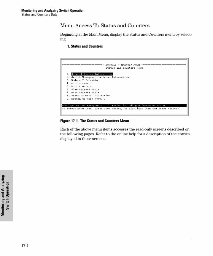
Monitoring and Analyzing Switch OperationStatus and Counters Data
Mon
itori
ng a
nd A
naly
zing
Sw
itch
Ope
ratio
n
Menu Access To Status and Counters
Beginning at the Main Menu, display the Status and Counters menu by select-ing:
1. Status and Counters
Figure 17-1. The Status and Counters Menu
Each of the above menu items accesses the read-only screens described on the following pages. Refer to the online help for a description of the entries displayed in these screens.
17-4
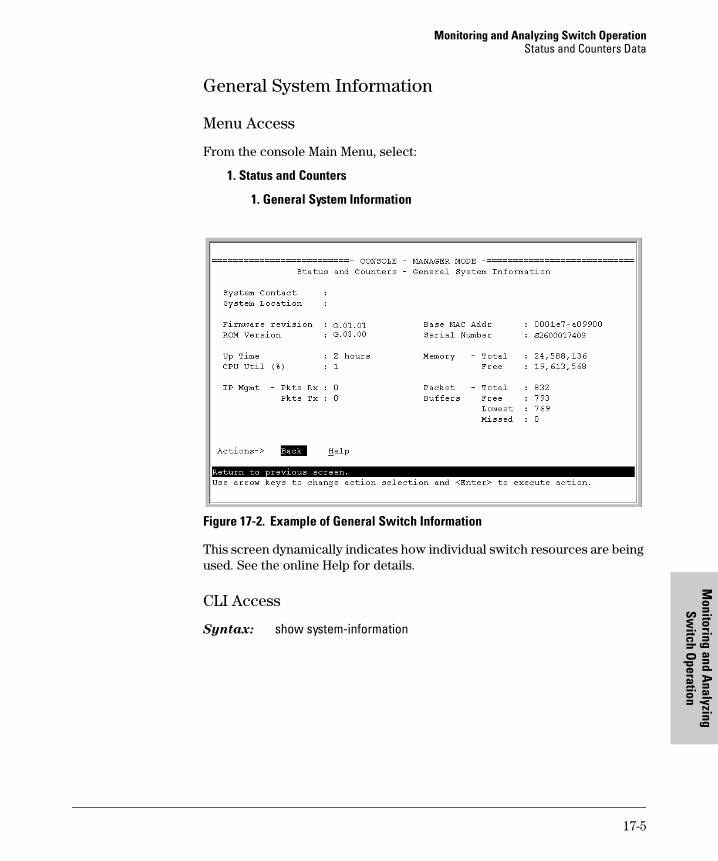
Monitoring and Analyzing Switch OperationStatus and Counters Data
Monitoring and A
nalyzing Sw
itch Operation
General System Information
Menu Access
From the console Main Menu, select:
1. Status and Counters
1. General System Information
Figure 17-2. Example of General Switch Information
This screen dynamically indicates how individual switch resources are being used. See the online Help for details.
CLI Access
Syntax: show system-information
17-5
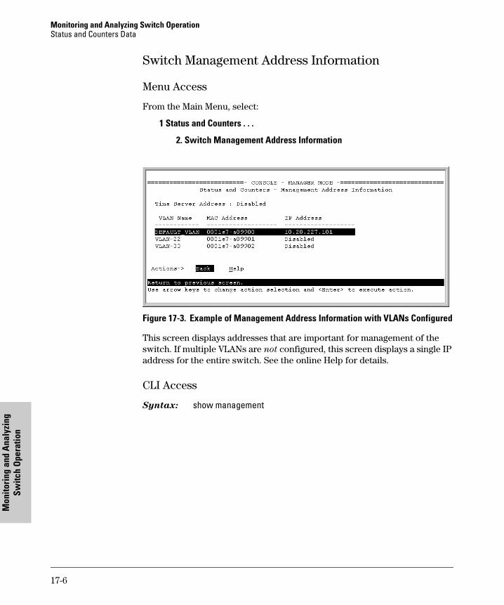
Monitoring and Analyzing Switch OperationStatus and Counters Data
Mon
itori
ng a
nd A
naly
zing
Sw
itch
Ope
ratio
n
Switch Management Address Information
Menu Access
From the Main Menu, select:
1 Status and Counters . . .
2. Switch Management Address Information
Figure 17-3. Example of Management Address Information with VLANs Configured
This screen displays addresses that are important for management of the switch. If multiple VLANs are not configured, this screen displays a single IP address for the entire switch. See the online Help for details.
CLI Access
Syntax: show management
17-6
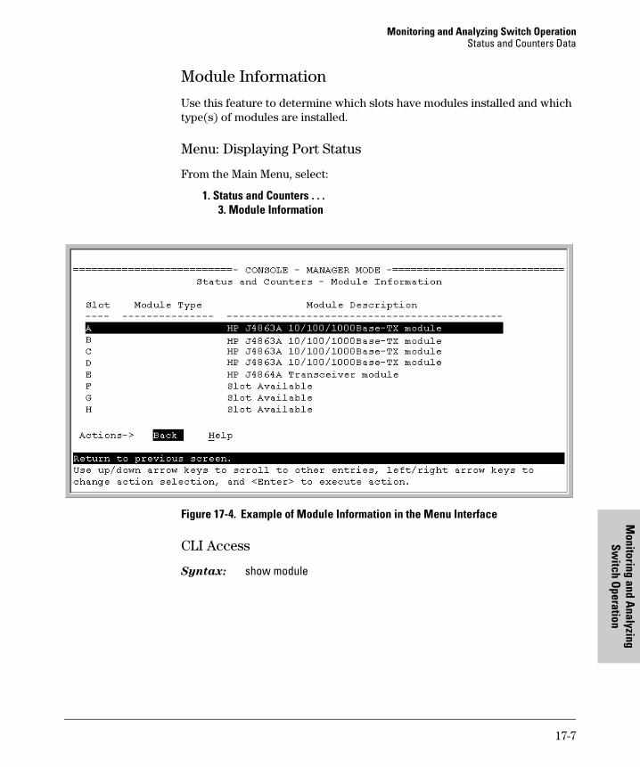
Monitoring and Analyzing Switch OperationStatus and Counters Data
Monitoring and A
nalyzing Sw
itch Operation
Module Information
Use this feature to determine which slots have modules installed and which type(s) of modules are installed.
Menu: Displaying Port Status
From the Main Menu, select:
1. Status and Counters . . . 3. Module Information
Figure 17-4. Example of Module Information in the Menu Interface
CLI Access
Syntax: show module
17-7
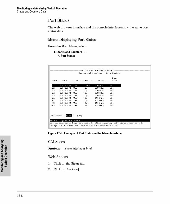
Monitoring and Analyzing Switch OperationStatus and Counters Data
Mon
itori
ng a
nd A
naly
zing
Sw
itch
Ope
ratio
n
Port Status
The web browser interface and the console interface show the same port status data.
Menu: Displaying Port Status
From the Main Menu, select:
1. Status and Counters . . . 4. Port Status
Figure 17-5. Example of Port Status on the Menu Interface
CLI Access
Syntax: show interfaces brief
Web Access
1. Click on the Status tab.
2. Click on [Port Status].
17-8
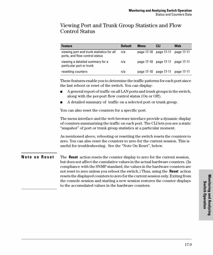
Monitoring and Analyzing Switch OperationStatus and Counters Data
Monitoring and A
nalyzing Sw
itch Operation
Viewing Port and Trunk Group Statistics and Flow Control Status
These features enable you to determine the traffic patterns for each port since the last reboot or reset of the switch. You can display:
� A general report of traffic on all LAN ports and trunk groups in the switch, along with the per-port flow control status (On or Off).
� A detailed summary of traffic on a selected port or trunk group.
You can also reset the counters for a specific port.
The menu interface and the web browser interface provide a dynamic display of counters summarizing the traffic on each port. The CLI lets you see a static “snapshot” of port or trunk group statistics at a particular moment.
As mentioned above, rebooting or resetting the switch resets the counters to zero. You can also reset the counters to zero for the current session. This is useful for troubleshooting. See the “Note On Reset”, below.
N o t e o n R e s e t The Reset action resets the counter display to zero for the current session, but does not affect the cumulative values in the actual hardware counters. (In compliance with the SNMP standard, the values in the hardware counters are not reset to zero unless you reboot the switch.) Thus, using the Reset action resets the displayed counters to zero for the current session only. Exiting from the console session and starting a new session restores the counter displays to the accumulated values in the hardware counters.
Feature Default Menu CLI Web
viewing port and trunk statistics for all ports, and flow control status
n/a page 17-10 page 17-11 page 17-11
viewing a detailed summary for a particular port or trunk
n/a page 17-10 page 17-11 page 17-11
resetting counters n/a page 17-10 page 17-11 page 17-11
17-9
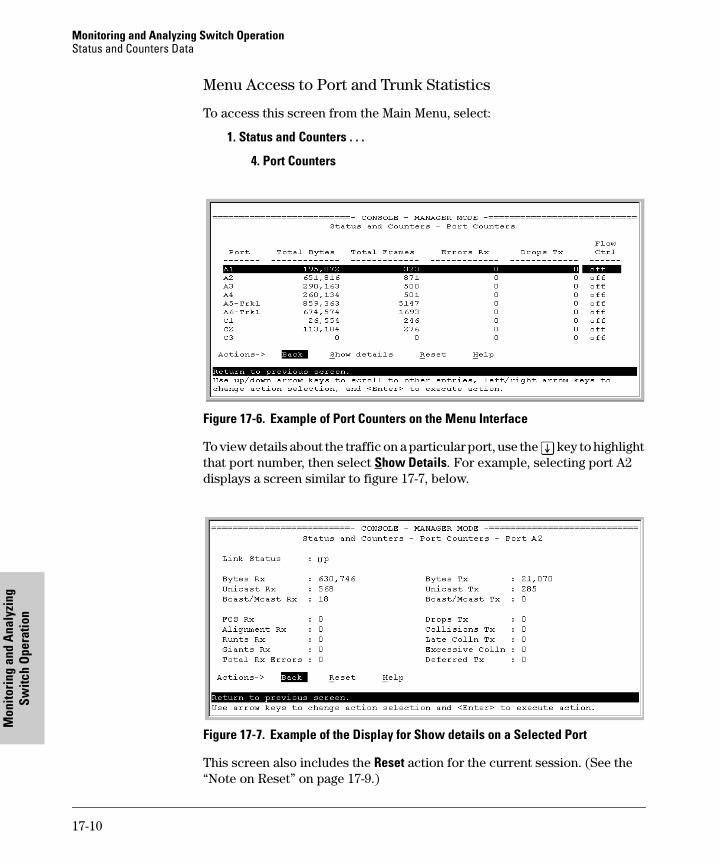
Monitoring and Analyzing Switch OperationStatus and Counters Data
Mon
itori
ng a
nd A
naly
zing
Sw
itch
Ope
ratio
n
Menu Access to Port and Trunk Statistics
To access this screen from the Main Menu, select:
1. Status and Counters . . .
4. Port Counters
Figure 17-6. Example of Port Counters on the Menu Interface
To view details about the traffic on a particular port, use the [v] key to highlight that port number, then select Show Details. For example, selecting port A2 displays a screen similar to figure 17-7, below.
Figure 17-7. Example of the Display for Show details on a Selected Port
This screen also includes the Reset action for the current session. (See the “Note on Reset” on page 17-9.)
17-10
Monitoring and Analyzing Switch OperationStatus and Counters Data
Monitoring and A
nalyzing Sw
itch Operation
CLI Access To Port and Trunk Group Statistics
To Display the Port Counter Summary Report. This command provides an overview of port activity for all ports on the switch.
Syntax: show interfaces
To Display a Detailed Traffic Summary for Specific Ports. This com-mand provides traffic details for the port(s) you specify.
Syntax: show interfaces [ethernet] <port-list>
To Reset the Port Counters for a Specific Port. This command resets the counters for the specified ports to zero for the current session. (See the “Note on Reset” on page 17-9.)
Syntax: clear statistics <[ethernet] port-list>
Web Browser Access To View Port and Trunk Group Statistics
1. Click on the Status tab.
2. Click on [Port Counters].
3. To reset the counters for a specific port, click anywhere in the row for that port, then click on [Refresh].
17-11
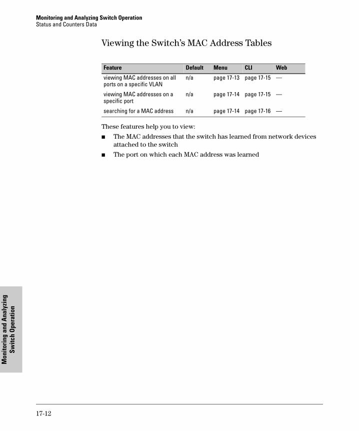
Monitoring and Analyzing Switch OperationStatus and Counters Data
Mon
itori
ng a
nd A
naly
zing
Sw
itch
Ope
ratio
n
Viewing the Switch’s MAC Address Tables
These features help you to view:
� The MAC addresses that the switch has learned from network devices attached to the switch
� The port on which each MAC address was learned
Feature Default Menu CLI Web
viewing MAC addresses on all ports on a specific VLAN
n/a page 17-13 page 17-15 —
viewing MAC addresses on a specific port
n/a page 17-14 page 17-15 —
searching for a MAC address n/a page 17-14 page 17-16 —
17-12
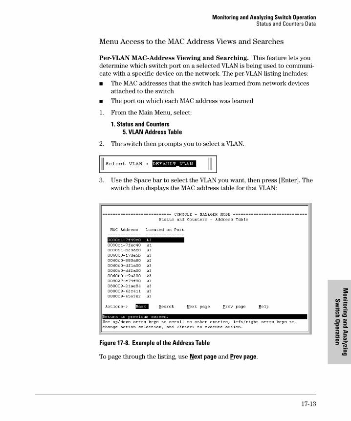
Monitoring and Analyzing Switch OperationStatus and Counters Data
Monitoring and A
nalyzing Sw
itch Operation
Menu Access to the MAC Address Views and Searches
Per-VLAN MAC-Address Viewing and Searching. This feature lets you determine which switch port on a selected VLAN is being used to communi-cate with a specific device on the network. The per-VLAN listing includes:
� The MAC addresses that the switch has learned from network devices attached to the switch
� The port on which each MAC address was learned
1. From the Main Menu, select:
1. Status and Counters5. VLAN Address Table
2. The switch then prompts you to select a VLAN.
3. Use the Space bar to select the VLAN you want, then press [Enter]. The switch then displays the MAC address table for that VLAN:
Figure 17-8. Example of the Address Table
To page through the listing, use Next page and Prev page.
17-13
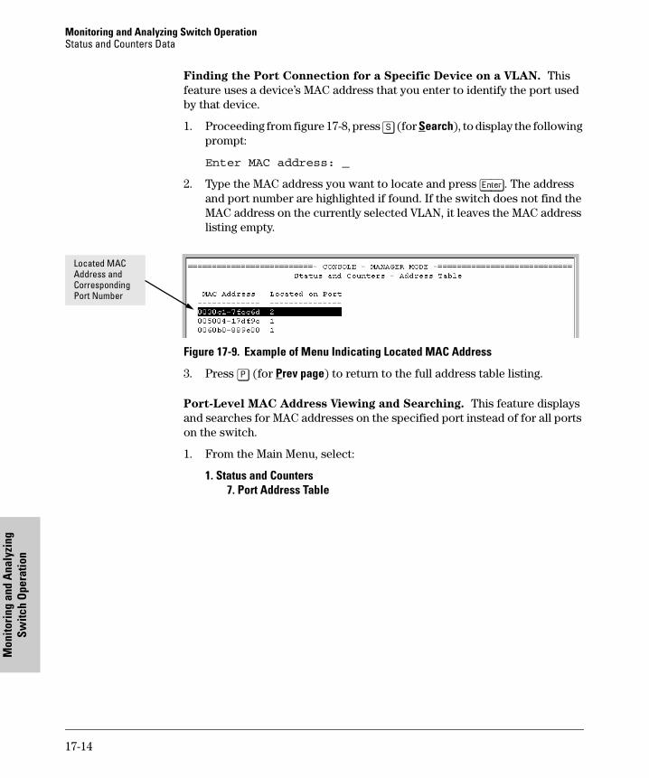
Monitoring and Analyzing Switch OperationStatus and Counters Data
Mon
itori
ng a
nd A
naly
zing
Sw
itch
Ope
ratio
n
Finding the Port Connection for a Specific Device on a VLAN. This feature uses a device’s MAC address that you enter to identify the port used by that device.
1. Proceeding from figure 17-8, press [S] (for Search), to display the following prompt:
Enter MAC address: _
2. Type the MAC address you want to locate and press [Enter]. The address and port number are highlighted if found. If the switch does not find the MAC address on the currently selected VLAN, it leaves the MAC address listing empty.
Figure 17-9. Example of Menu Indicating Located MAC Address
3. Press [P] (for Prev page) to return to the full address table listing.
Port-Level MAC Address Viewing and Searching. This feature displays and searches for MAC addresses on the specified port instead of for all ports on the switch.
1. From the Main Menu, select:
1. Status and Counters7. Port Address Table
Located MAC Address and Corresponding Port Number
17-14

Monitoring and Analyzing Switch OperationStatus and Counters Data
Monitoring and A
nalyzing Sw
itch Operation
Figure 17-10.Listing MAC Addresses for a Specific Port
2. Use the Space bar to select the port you want to list or search for MAC addresses, then press [Enter] to list the MAC addresses detected on that port.
Determining Whether a Specific Device Is Connected to the Selected
Port. Proceeding from step 2, above:
1. Press [S] (for Search), to display the following prompt:
Enter MAC address: _
2. Type the MAC address you want to locate and press [Enter]. The address is highlighted if found. If the switch does not find the address, it leaves the MAC address listing empty.
3. Press [P] (for Prev page) to return to the previous per-port listing.
CLI Access for MAC Address Views and Searches
Syntax: show mac-address [vlan <vlan-id>][ethernet]<port-list>][<mac-addr>]
To List All Learned MAC Addresses on the Switch, with The Port
Number on Which Each MAC Address Was Learned.
HP4108> show mac-address
To List All Learned MAC Addresses on one or more ports, with Their
Prompt for Selecting the Port To Search
17-15
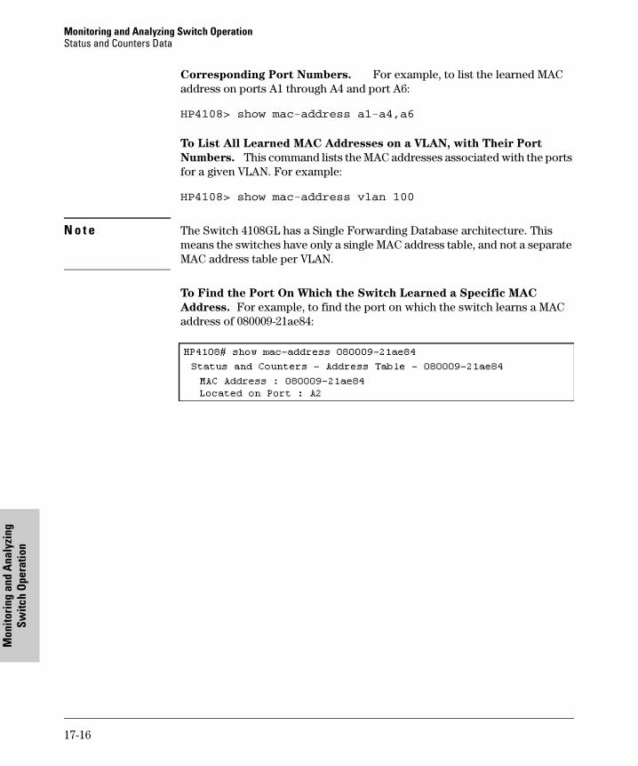
Monitoring and Analyzing Switch OperationStatus and Counters Data
Mon
itori
ng a
nd A
naly
zing
Sw
itch
Ope
ratio
n
Corresponding Port Numbers. For example, to list the learned MAC address on ports A1 through A4 and port A6:
HP4108> show mac-address a1-a4,a6
To List All Learned MAC Addresses on a VLAN, with Their Port
Numbers. This command lists the MAC addresses associated with the ports for a given VLAN. For example:
HP4108> show mac-address vlan 100
N o t e The Switch 4108GL has a Single Forwarding Database architecture. This means the switches have only a single MAC address table, and not a separate MAC address table per VLAN.
To Find the Port On Which the Switch Learned a Specific MAC
Address. For example, to find the port on which the switch learns a MAC address of 080009-21ae84:
17-16
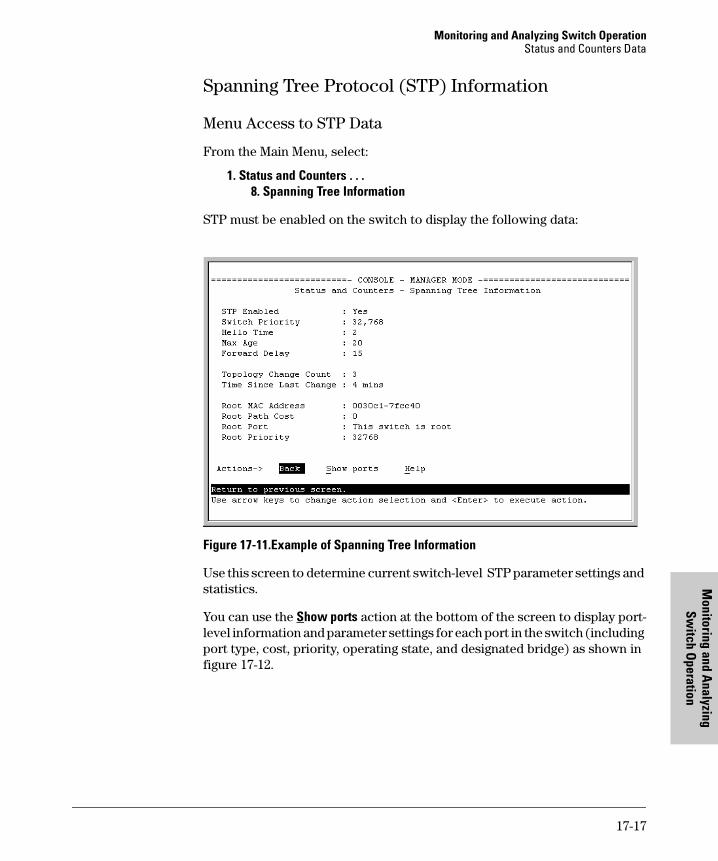
Monitoring and Analyzing Switch OperationStatus and Counters Data
Monitoring and A
nalyzing Sw
itch Operation
Spanning Tree Protocol (STP) Information
Menu Access to STP Data
From the Main Menu, select:
1. Status and Counters . . .8. Spanning Tree Information
STP must be enabled on the switch to display the following data:
Figure 17-11.Example of Spanning Tree Information
Use this screen to determine current switch-level STP parameter settings and statistics.
You can use the Show ports action at the bottom of the screen to display port-level information and parameter settings for each port in the switch (including port type, cost, priority, operating state, and designated bridge) as shown in figure 17-12.
17-17
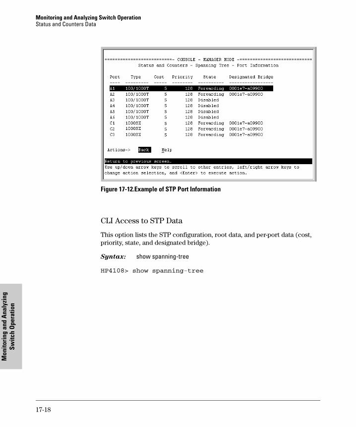
Monitoring and Analyzing Switch OperationStatus and Counters Data
Mon
itori
ng a
nd A
naly
zing
Sw
itch
Ope
ratio
n
Figure 17-12.Example of STP Port Information
CLI Access to STP Data
This option lists the STP configuration, root data, and per-port data (cost, priority, state, and designated bridge).
Syntax: show spanning-tree
HP4108> show spanning-tree
17-18
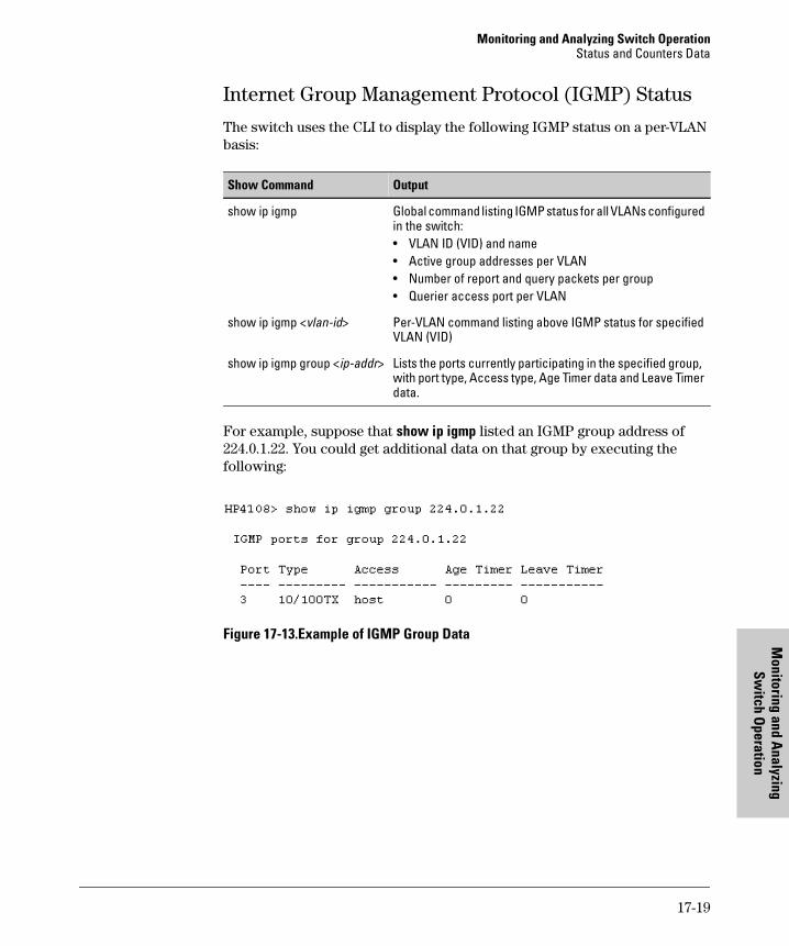
Monitoring and Analyzing Switch OperationStatus and Counters Data
Monitoring and A
nalyzing Sw
itch Operation
Internet Group Management Protocol (IGMP) Status
The switch uses the CLI to display the following IGMP status on a per-VLAN basis:
For example, suppose that show ip igmp listed an IGMP group address of 224.0.1.22. You could get additional data on that group by executing the following:
Figure 17-13.Example of IGMP Group Data
Show Command Output
show ip igmp Global command listing IGMP status for all VLANs configured in the switch:• VLAN ID (VID) and name• Active group addresses per VLAN• Number of report and query packets per group• Querier access port per VLAN
show ip igmp <vlan-id> Per-VLAN command listing above IGMP status for specified VLAN (VID)
show ip igmp group <ip-addr> Lists the ports currently participating in the specified group, with port type, Access type, Age Timer data and Leave Timer data.
17-19
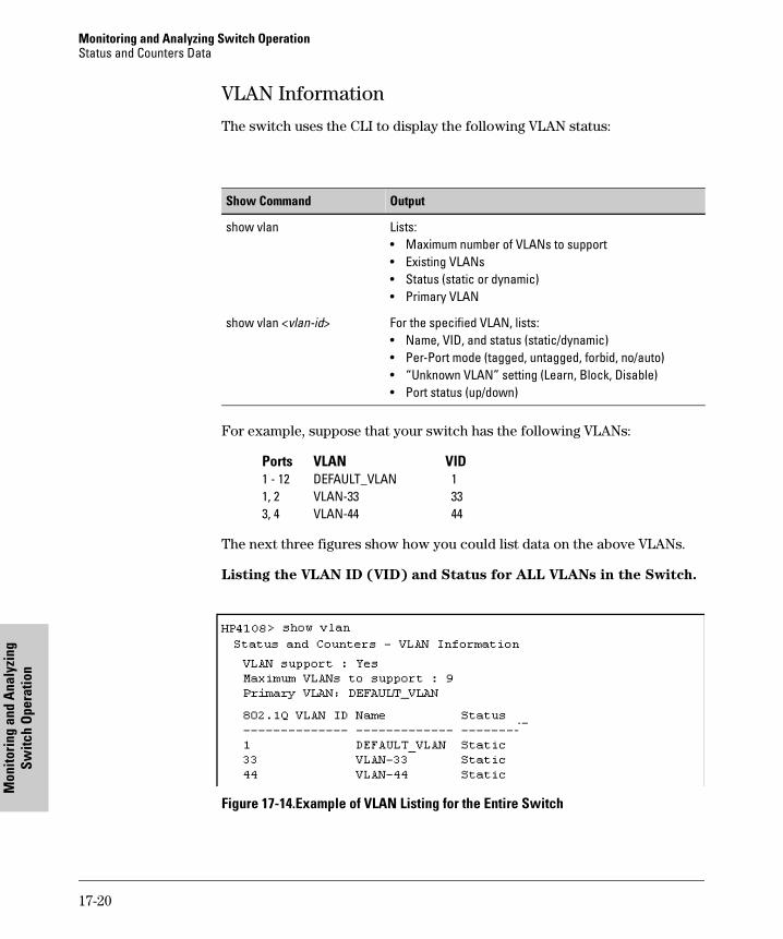
Monitoring and Analyzing Switch OperationStatus and Counters Data
Mon
itori
ng a
nd A
naly
zing
Sw
itch
Ope
ratio
n
VLAN Information
The switch uses the CLI to display the following VLAN status:
For example, suppose that your switch has the following VLANs:
Ports VLAN VID1 - 12 DEFAULT_VLAN 11, 2 VLAN-33 333, 4 VLAN-44 44
The next three figures show how you could list data on the above VLANs.
Listing the VLAN ID (VID) and Status for ALL VLANs in the Switch.
Figure 17-14.Example of VLAN Listing for the Entire Switch
Show Command Output
show vlan Lists:• Maximum number of VLANs to support• Existing VLANs• Status (static or dynamic)• Primary VLAN
show vlan <vlan-id> For the specified VLAN, lists:• Name, VID, and status (static/dynamic)• Per-Port mode (tagged, untagged, forbid, no/auto)• “Unknown VLAN” setting (Learn, Block, Disable)• Port status (up/down)
17-20
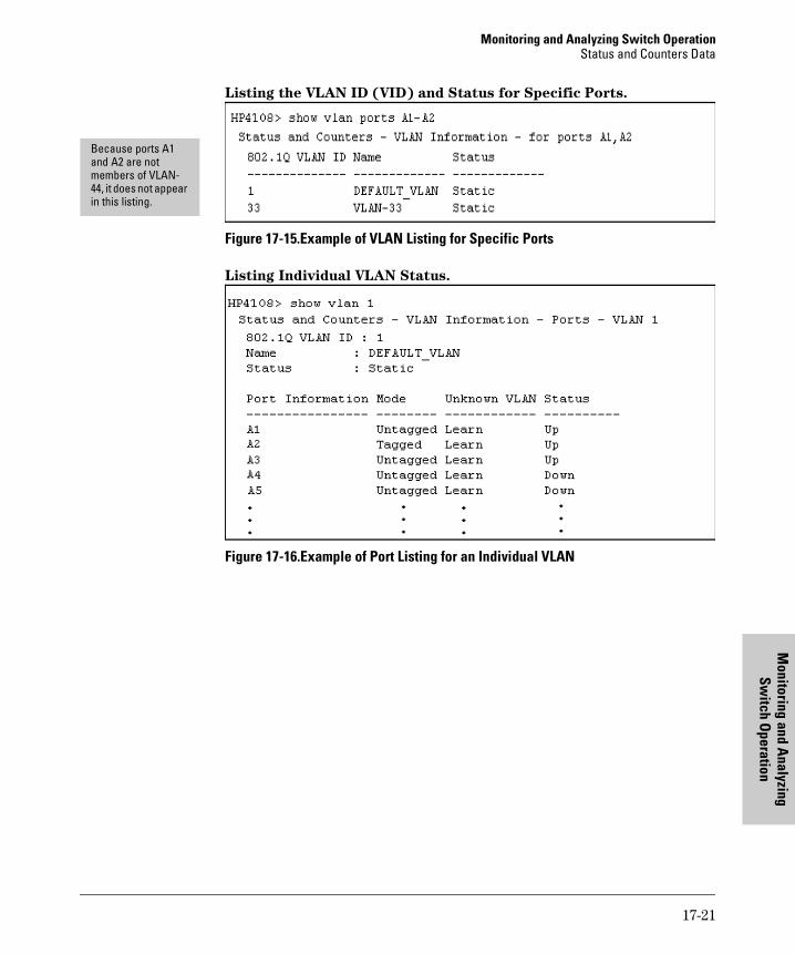
Monitoring and Analyzing Switch OperationStatus and Counters Data
Monitoring and A
nalyzing Sw
itch Operation
Listing the VLAN ID (VID) and Status for Specific Ports.
Figure 17-15.Example of VLAN Listing for Specific Ports
Listing Individual VLAN Status.
Figure 17-16.Example of Port Listing for an Individual VLAN
Because ports A1 and A2 are not members of VLAN-44, it does not appear in this listing.
17-21
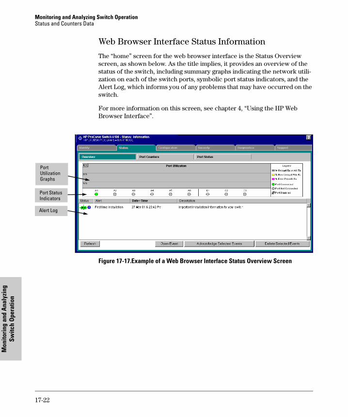
Monitoring and Analyzing Switch OperationStatus and Counters Data
Mon
itori
ng a
nd A
naly
zing
Sw
itch
Ope
ratio
n
Web Browser Interface Status Information
The “home” screen for the web browser interface is the Status Overview screen, as shown below. As the title implies, it provides an overview of the status of the switch, including summary graphs indicating the network utili-zation on each of the switch ports, symbolic port status indicators, and the Alert Log, which informs you of any problems that may have occurred on the switch.
For more information on this screen, see chapter 4, “Using the HP Web Browser Interface”.
Figure 17-17.Example of a Web Browser Interface Status Overview Screen
Port Utilization Graphs
Port Status Indicators
Alert Log
17-22
Monitoring and Analyzing Switch OperationPort Monitoring Features
Monitoring and A
nalyzing Sw
itch Operation
Port Monitoring Features
Port Monitoring Features
You can designate a port for monitoring incoming traffic of one or more other ports on the switch. The switch monitors the network activity by copying all traffic inbound on the specified ports to the designated monitoring port, to which a network analyzer can be attached.
N o t e Port trunk groups cannot be used as a monitoring port.
It is possible, when monitoring multiple ports in networks with high traffic levels, to copy more traffic to a monitor port than the link can support. In this case, some packets may not be copied to the monitor port.
Feature Default Menu CLI Web
display monitoring configuration
disabled page 17-24 page 17-26 page 17-27
configure the monitor port(s) ports: none page 17-24 page 17-26 page 17-27
selecting or removing ports none selected page 17-24 page 17-27 page 17-27
17-23
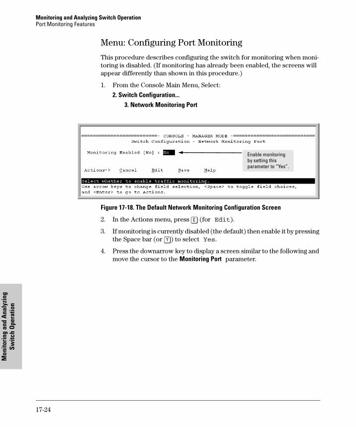
Monitoring and Analyzing Switch OperationPort Monitoring Features
Mon
itori
ng a
nd A
naly
zing
Sw
itch
Ope
ratio
n
Menu: Configuring Port Monitoring
This procedure describes configuring the switch for monitoring when moni-toring is disabled. (If monitoring has already been enabled, the screens will appear differently than shown in this procedure.)
1. From the Console Main Menu, Select:
2. Switch Configuration...3. Network Monitoring Port
Figure 17-18. The Default Network Monitoring Configuration Screen
2. In the Actions menu, press [E] (for Edit).
3. If monitoring is currently disabled (the default) then enable it by pressing the Space bar (or [Y]) to select Yes.
4. Press the downarrow key to display a screen similar to the following and move the cursor to the Monitoring Port parameter.
Enable monitoring by setting this parameter to “Yes”.
17-24
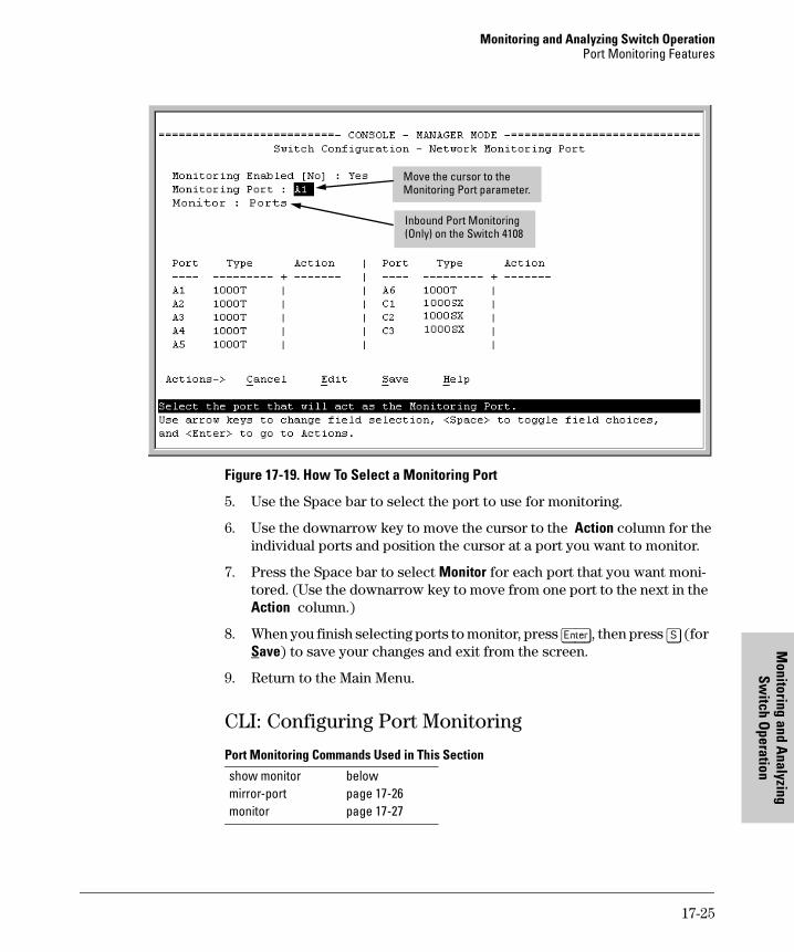
Monitoring and Analyzing Switch OperationPort Monitoring Features
Monitoring and A
nalyzing Sw
itch Operation
Figure 17-19. How To Select a Monitoring Port
5. Use the Space bar to select the port to use for monitoring.
6. Use the downarrow key to move the cursor to the Action column for the individual ports and position the cursor at a port you want to monitor.
7. Press the Space bar to select Monitor for each port that you want moni-tored. (Use the downarrow key to move from one port to the next in the Action column.)
8. When you finish selecting ports to monitor, press [Enter], then press [S] (for Save) to save your changes and exit from the screen.
9. Return to the Main Menu.
CLI: Configuring Port Monitoring
Port Monitoring Commands Used in This Section
Move the cursor to the Monitoring Port parameter.
Inbound Port Monitoring (Only) on the Switch 4108
show monitormirror-portmonitor
belowpage 17-26page 17-27
17-25
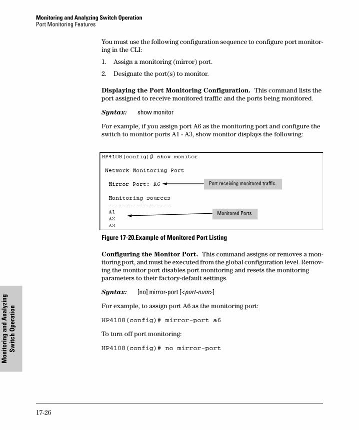
Monitoring and Analyzing Switch OperationPort Monitoring Features
Mon
itori
ng a
nd A
naly
zing
Sw
itch
Ope
ratio
n
You must use the following configuration sequence to configure port monitor-ing in the CLI:
1. Assign a monitoring (mirror) port.
2. Designate the port(s) to monitor.
Displaying the Port Monitoring Configuration. This command lists the port assigned to receive monitored traffic and the ports being monitored.
Syntax: show monitor
For example, if you assign port A6 as the monitoring port and configure the switch to monitor ports A1 - A3, show monitor displays the following:
Figure 17-20.Example of Monitored Port Listing
Configuring the Monitor Port. This command assigns or removes a mon-itoring port, and must be executed from the global configuration level. Remov-ing the monitor port disables port monitoring and resets the monitoring parameters to their factory-default settings.
Syntax: [no] mirror-port [<port-num>]
For example, to assign port A6 as the monitoring port:
HP4108(config)# mirror-port a6
To turn off port monitoring:
HP4108(config)# no mirror-port
Port receiving monitored traffic.
Monitored Ports
17-26
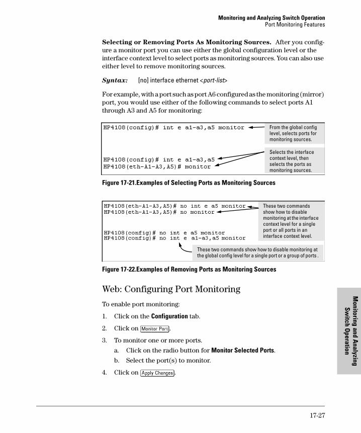
Monitoring and Analyzing Switch OperationPort Monitoring Features
Monitoring and A
nalyzing Sw
itch Operation
Selecting or Removing Ports As Monitoring Sources. After you config-ure a monitor port you can use either the global configuration level or the interface context level to select ports as monitoring sources. You can also use either level to remove monitoring sources.
Syntax: [no] interface ethernet <port-list>
For example, with a port such as port A6 configured as the monitoring (mirror) port, you would use either of the following commands to select ports A1 through A3 and A5 for monitoring:
Figure 17-21.Examples of Selecting Ports as Monitoring Sources
Figure 17-22.Examples of Removing Ports as Monitoring Sources
Web: Configuring Port Monitoring
To enable port monitoring:
1. Click on the Configuration tab.
2. Click on [Monitor Port].
3. To monitor one or more ports.
a. Click on the radio button for Monitor Selected Ports. b. Select the port(s) to monitor.
4. Click on [Apply Changes].
From the global config level, selects ports for monitoring sources.
Selects the interface context level, then selects the ports as monitoring sources.
These two commands show how to disable monitoring at the interface context level for a single port or all ports in an interface context level.
These two commands show how to disable monitoring at the global config level for a single port or a group of ports .
17-27

Monitoring and Analyzing Switch OperationPort Monitoring Features
Mon
itori
ng a
nd A
naly
zing
Sw
itch
Ope
ratio
n
To remove port monitoring:
1. Click on the Monitoring Off radio button.
2. Click on [Apply Changes].
For web-based Help on how to use the web browser interface screen, click on the [?] button provided on the web browser screen.
17-28
Troubleshootin
18
Troubleshooting
Contents
Overview . . . . . . . . . . . . . . . . . . . . . . . . . . . . . . . . . . . . . . . . . . . . . . . . . . . . . 18-2
Troubleshooting Approaches . . . . . . . . . . . . . . . . . . . . . . . . . . . . . . . . . . . . 18-3
Browser or Telnet Access Problems . . . . . . . . . . . . . . . . . . . . . . . . . . . . . . 18-4
Unusual Network Activity . . . . . . . . . . . . . . . . . . . . . . . . . . . . . . . . . . . . . . . 18-6General Problems . . . . . . . . . . . . . . . . . . . . . . . . . . . . . . . . . . . . . . . 18-6Troubleshooting CDP Operation . . . . . . . . . . . . . . . . . . . . . . . . . . 18-7IGMP-Related Problems . . . . . . . . . . . . . . . . . . . . . . . . . . . . . . . . . 18-8Problems Related to Spanning-Tree Protocol (STP) . . . . . . . . . . 18-9Stacking-Related Problems . . . . . . . . . . . . . . . . . . . . . . . . . . . . . . . 18-9TACACS-Related Problems . . . . . . . . . . . . . . . . . . . . . . . . . . . . . . . 18-9TimeP, SNTP, or Gateway Problems . . . . . . . . . . . . . . . . . . . . . . 18-11VLAN-Related Problems . . . . . . . . . . . . . . . . . . . . . . . . . . . . . . . . 18-11Troubleshooting TACACS+ Operation . . . . . . . . . . . . . . . . . . . . 18-13
Using the Event Log To Identify Problem Sources . . . . . . . . . . . . . . . . . 18-16
Menu: Entering and Navigating in the Event Log . . . . . . . . . . . . . . . 18-17
CLI: . . . . . . . . . . . . . . . . . . . . . . . . . . . . . . . . . . . . . . . . . . . . . . . . . . . . . 18-18
Diagnostic Tools . . . . . . . . . . . . . . . . . . . . . . . . . . . . . . . . . . . . . . . . . . . . . . 18-19
Port Auto-Negotiation . . . . . . . . . . . . . . . . . . . . . . . . . . . . . . . . . . . . . . 18-19
Ping and Link Tests . . . . . . . . . . . . . . . . . . . . . . . . . . . . . . . . . . . . . . . . 18-19Web: Executing Ping or Link Tests . . . . . . . . . . . . . . . . . . . . . . . 18-21CLI: Ping or Link Tests . . . . . . . . . . . . . . . . . . . . . . . . . . . . . . . . . 18-22
Displaying the Configuration File . . . . . . . . . . . . . . . . . . . . . . . . . . . . 18-24CLI: Viewing the Configuration File . . . . . . . . . . . . . . . . . . . . . . 18-24Web: Viewing the Configuration File . . . . . . . . . . . . . . . . . . . . . . 18-24
CLI Administrative and Troubleshooting Commands . . . . . . . . . . . 18-25
Restoring the Factory-Default Configuration . . . . . . . . . . . . . . . . . . . . . . 18-26CLI: Resetting to the Factory-Default Configuration . . . . . . . . 18-26Clear/Reset: Resetting to the Factory-Default Configuration . 18-26
Restoring a Flash Image . . . . . . . . . . . . . . . . . . . . . . . . . . . . . . . . . . . . . . . 18-27
18-1
g
TroubleshootingOverview
Trou
bles
hoot
ing
Overview
This chapter addresses performance-related network problems that can be caused by topology, switch configuration, and the effects of other devices or their configurations on switch operation. (For switch-specific information on hardware problems indicated by LED behavior, cabling requirements, and other potential hardware-related problems, refer to the installation guide you received with the switch.)
N o t e HP periodically places switch software updates on the HP Procurve website. HP recommends that you check this website for software updates that may have fixed a problem you are experiencing.
For information on support and warranty provisions, see the Support and Warranty booklet shipped with the switch.
18-2
TroubleshootingTroubleshooting Approaches
Troubleshootin
Troubleshooting ApproachesUse these approaches to diagnose switch problems:
� Check the HP Procurve website for software updates that may have solved your problem: http://www.hp.com/go/hpprocurve
� Check the switch LEDs for indications of proper switch operation:
• Each switch port has a Link LED that should light whenever an active network device is connected to the port.
• Problems with the switch hardware and software are indicated by flashing the Fault and other switch LEDs.
See the Installation Guide shipped with the switch for a description of the LED behavior and information on using the LEDs for trouble-shooting.
� Check the network topology/installation. See the Installation Guide shipped with the switch for topology information.
� Check cables for damage, correct type, and proper connections. You should also use a cable tester to check your cables for compliance to the relevant IEEE 802.3 specification. See the Installation Guide shipped with the switch for correct cable types and connector pin-outs.
� Use HP TopTools for Hubs & Switches (if installed on your network) to help isolate problems and recommend solutions. HP TopTools is shipped at no extra cost with the switch.
� Use the Port Utilization Graph and Alert Log in the web browser interface included in the switch to help isolate problems. See Chapter 4, “Using the HP Web Browser Interface” for operating information. These tools are available through the web browser interface:
• Port Utilization Graph
• Alert Log
• Port Status and Port Counters screens
• Diagnostic tools (Link test, Ping test, configuration file browser)
� For help in isolating problems, use the easy-to-access switch console built into the switch or Telnet to the switch console. See chapter 4, “Using the Switch Console Interface” for operating information. These tools are available through the switch console
• Status and Counters screens
• Event Log
• Diagnostics tools (Link test, Ping test, configuration file browser, and advanced user commands)
18-3
g
TroubleshootingBrowser or Telnet Access Problems
Trou
bles
hoot
ing
Browser or Telnet Access Problems
Cannot access the web browser interface:
� Access may be disabled by the Web Agent Enabled parameter in the switch console. Check the setting on this parameter by selecting:
2. Switch Configuration . . .1. System Information
� The switch may not have the correct IP address, subnet mask or gateway. Verify by connecting a console to the switch’s Console port and selecting:
2. Switch Configuration . . .5. IP Configuration
Note: If DHCP/Bootp is used to configure the switch, the IP addressing can be verified by selecting:
1. Status and Counters . . .
2. Switch Management Address Information
also check the DHCP/Bootp server configuration to verify correct IP addressing.
� If you are using DHCP to acquire the IP address for the switch, the IP address “lease time” may have expired so that the IP address has changed. For more information on how to “reserve” an IP address, refer to the documentation for the DHCP application that you are using.
� If one or more IP-Authorized managers are configured, the switch allows web browser access only to a device having an authorized IP address. For more information on IP Authorized managers, see Chapter 10, “Using Authorized IP Managers for Increased Management Security”.
� Java™ applets may not be running on the web browser. They are required for the switch web browser interface to operate correctly. See the online Help on your web browser for how to run the Java applets.
� Wrong OS type or version. See “Web Browser Interface Requirements” on page 4-4.
� Wrong browser type or version. See “Web Browser Interface Require-ments” on page 4-4.
18-4
TroubleshootingBrowser or Telnet Access Problems
Troubleshootin
Cannot Telnet into the switch console from a station on the network:
� Telnet access may be disabled by the Inbound Telnet Enabled parameter in the System Information screen of the menu interface:
2. Switch Configuration1. System Information
� The switch may not have the correct IP address, subnet mask, or gateway. Verify by connecting a console to the switch’s Console port and selecting:
2. Switch Configuration5. IP Configuration
Note: If DHCP/Bootp is used to configure the switch, see the Note, above.
� If you are using DHCP to acquire the IP address for the switch, the IP address “lease time” may have expired so that the IP address has changed. For more information on how to “reserve” an IP address, refer to the documentation for the DHCP application that you are using.
� If one or more IP-Authorized managers are configured, the switch allows inbound telnet access only to a device having an authorized IP address. For more information on IP Authorized managers, see Chapter 10, “Using Authorized IP Managers for Increased Management Security”.
18-5
g
TroubleshootingUnusual Network Activity
Trou
bles
hoot
ing
Unusual Network Activity
Network activity that fails to meet accepted norms may indicate a hardware problem with one or more of the network components, possibly including the switch. Such problems can also be caused by a network loop or simply too much traffic for the network as it is currently designed and implemented. Unusual network activity is usually indicated by the LEDs on the front of the switch or measured with the switch console interface or with a network management tool such as the HP TopTools for Hubs & Switches. Refer to the Installation Guide you received with the switch for information on using LEDs to identify unusual network activity.
A topology loop can also cause excessive network activity. The event log "FFI" messages can be indicative of this type of problem.
General Problems
The network runs slow; processes fail; users cannot access servers or
other devices. Broadcast storms may be occurring in the network. These may be due to redundant links between nodes.
• If you are configuring a port trunk, finish configuring the ports in the trunk before connecting the related cables. Otherwise you may inad-vertently create a number of redundant links (i.e. topology loops) that will cause broadcast storms.
• Turn on Spanning Tree Protocol to block redundant links (i.e. topol-ogy loops)
• Check for FFI messages in the Event Log.
Duplicate IP Addresses. This is indicated by this Event Log message:
ip: Invalid ARP source: IP address on IP address
where: both instances of IP address are the same address, indicating the switch’s IP address has been duplicated somewhere on the network.
Duplicate IP Addresses in a DHCP Network. If you use a DHCP server to assign IP addresses in your network and you find a device with a valid IP address that does not appear to communicate properly with the server or other devices, a duplicate IP address may have been issued by the server. This can occur if a client has not released a DHCP-assigned IP address after the intended expiration time and the server “leases” the address to another device.
18-6
TroubleshootingUnusual Network Activity
Troubleshootin
This can also happen, for example, if the server is first configured to issue IP addresses with an unlimited duration, then is subsequently configured to issue IP addresses that will expire after a limited duration. One solution is to configure “reservations” in the DHCP server for specific IP addresses to be assigned to devices having specific MAC addresses. For more information, refer to the documentation for the DHCP server.
One indication of a duplicate IP address in a DHCP network is this Event Log message:
ip: Invalid ARP source: IP address on IP address
where: both instances of IP address are the same address, indicating the IP address that has been duplicated somewhere on the network.
The Switch Has Been Configured for DHCP/Bootp Operation, But Has
Not Received a DHCP or Bootp Reply. When the switch is first config-ured for DHCP/Bootp operation, or if it is rebooted with this configuration, it immediately begins sending request packets on the network. If the switch does not receive a reply to its DHCP/Bootp requests, it continues to periodically send request packets, but with decreasing frequency. Thus, if a DHCP or Bootp server is not available or accessible to the switch when DHCP/Bootp is first configured, the switch may not immediately receive the desired configuration. After verifying that the server has become accessible to the switch, reboot the switch to re-start the process.
Troubleshooting CDP Operation
The switch does not appear in the CDP Neighbors table of an adjacent
CDP Device. This may be due to any of the following:
� Either the port connecting the switch to the adjacent device is not a member of an untagged VLAN or any Untagged VLAN to which the port belongs does not have an IP address.
� If there is more than one physical path between the switch and the other CDP device and STP is running on the switch, then STP will block the redundant link(s). In this case, the switch port on the remaining open link may not be a member of an untagged VLAN, or any untagged VLANs to which the port belongs may not have an IP address.
� The adjacent device’s CDP Neighbors table may be full. Refer to the documentation provided for the adjacent CDP device to determine the table’s capacity, and then view the device’s Neighbors table to determine whether it is full.
18-7
g
TroubleshootingUnusual Network Activity
Trou
bles
hoot
ing
One or more CDP neighbors appear intermittently or not at all in the
switch’s CDP Neighbors table. This may be caused by more than 60 neigh-boring devices sending CDP packets to the switch. Exceeding the 60-neighbor limit can occur, for example, where multiple neighbors are connected to the switch through non-CDP devices such as many hubs.
The Same CDP Switch or Router Appears on More Than One Port in
the CDP Neighbors Table. Where CDP is running, a switch or router that is the STP root transmits outbound CDP packets over all links, including redun-dant links that STP may be blocking in non-root devices. In this case, the non-root device shows an entry in its CDP Neighbors table for every port on which it receives a CDP packet from the root device. See “Effect of Spanning Tree (STP) On CDP Packet Transmission” on page 12-23.
IGMP-Related Problems
IP Multicast (IGMP) Traffic That Is Directed By IGMP Does Not Reach
IGMP Hosts or a Multicast Router Connected to a Port. IGMP must be enabled on the switch and the affected port must be configured for “Auto” or “Forward” operation.
IP Multicast Traffic Floods Out All Ports; IGMP Does Not Appear To
Filter Traffic. The IGMP feature does not operate if the switch or VLAN does not have an IP address configured manually or obtained through DHCP/Bootp. To verify whether an IP address is configured for the switch or VLAN, do either of the following:
� Try Using the Web Browser Interface: If you can access the web browser interface, then an IP address is configured.
� Try To Telnet to the Switch Console: If you can Telnet to the switch, then an IP address is configured.
� Using the Switch Console Interface: From the Main Menu, check the Management Address Information screen by clicking on
1. Status and Counters2. Switch Management Address Information
18-8
TroubleshootingUnusual Network Activity
Troubleshootin
Problems Related to Spanning-Tree Protocol (STP)
C a u t i o n If you enable STP, it is recommended that you leave the remainder of the STP parameter settings at their default values until you have had an opportunity to evaluate STP performance in your network. Because incorrect STP settings can adversely affect network performance, you should avoid making changes without having a strong understanding of how STP operates. To learn the details of STP operation, refer to the IEEE 802.1d standard.
Broadcast Storms Appearing in the Network. This can occur when there are physical loops (redundant links) in the topology.Where this exists, you should enable STP on all bridging devices in the topology in order for the loop to be detected.
STP Blocks a Link in a VLAN Even Though There Are No Redundant
Links in that VLAN. In 802.1Q-compliant switches such as the Switch 4108GL, STP blocks redundant physical links even if they are in separate VLANs. A solution is to use only one, multiple-VLAN (tagged) link between the devices. Also, if ports are available, you can improve the bandwidth in this situation by using a port trunk. See “STP Operation with 802.1Q VLANs” on page 16-12.
Stacking-Related Problems
The Stack Commander Cannot Locate any Candidates. Stacking oper-ates on the primary VLAN, which in the default configuration is the DEFAULT_VLAN. However, if another VLAN has been configured as the primary VLAN, and the Commander is not on the primary VLAN, then the Commander will not detect Candidates on the primary VLAN.
TACACS-Related Problems
Event Log. When troubleshooting TACACS+ operation, check the switch’s Event Log for indications of problem areas.
All Users Are Locked Out of Access to the Switch. If the switch is func-tioning properly, but no username/password pairs result in console or Telnet access to the switch, the problem may be due to how the TACACS+ server and/or the switch are configured. Use one of the following methods to recover:
� Access the TACACS+ server application and adjust or remove the configuration parameters controlling access to the switch.
18-9
g
TroubleshootingUnusual Network Activity
Trou
bles
hoot
ing
� If the above method does not work, try eliminating configuration changes in the switch that have not been saved to flash (boot-up configuration) by causing the switch to reboot from the boot-up configuration (which includes only the configuration changes made prior to the last write memory command.) If you did not use write memory to save the authentication configuration to flash, then pressing the Reset button or cycling the power reboots the switch with the boot-up configuration.
� Disconnect the switch from network access to any TACACS+ servers and then log in to the switch using either Telnet or direct console port access. Because the switch cannot access a TACACS+ server, it will default to local authentication. You can then use the switch’s local Operator or Manager username/password pair to log on.
� As a last resort, use the Clear/Reset button combination to reset the switch to its factory default boot-up configuration. Taking this step means you will have to reconfigure the switch to return it to operation in your network.
No Communication Between the Switch and the TACACS+ Server
Application. If the switch can access the server device (that is, it can ping the server), then a configuration error may be the problem. Some possiblities include:
� The server IP address configured with the switch’s tacacs-server host command may not be correct. (Use the switch’s show tacacs-server command to list the TACACS+ server IP address.)
� The encryption key configured in the server does not match the encryption key configured in the switch (by using the tacacs-server key command). Verify the key in the server and compare it to the key configured in the switch. (Use show tacacs-server to list the global key. Use show config or show config running to list any server-specific keys.)
� The accessible TACACS+ servers are not configured to provide service to the switch.
Access Is Denied Even Though the Username/Password Pair Is
Correct. Some reasons for denial include the following parameters controlled by your TACACS+ server application:
� The account has expired.
� The access attempt is through a port that is not allowed for the account.
18-10
TroubleshootingUnusual Network Activity
Troubleshootin
� The time quota for the account has been exhausted.
� The time credit for the account has expired.
� The access attempt is outside of the timeframe allowed for the account.
� The allowed number of concurrent logins for the account has been exceeded
For more help, refer to the documentation provided with your TACACS+ server application.
Unknown Users Allowed to Login to the Switch. Your TACACS+ appli-cation may be configured to allow access to unknown users by assigning them the privileges included in a default user profile. Refer to the documentation provided with your TACACS+ server application.
System Allows Fewer Login Attempts than Specified in the Switch
Configuration. Your TACACS+ server application may be configured to allow fewer login attempts than you have configured in the switch with the aaa authentication num-attempts command.
TimeP, SNTP, or Gateway Problems
The Switch Cannot Find the Time Server or the Configured Gateway .
TimeP, SNTP, and Gateway access are through the primary VLAN, which in the default configuration is the DEFAULT_VLAN. If the primary VLAN has been moved to another VLAN, it may be disabled or does not have ports assigned to it.
VLAN-Related Problems
Monitor Port. When using the monitor port in a multiple VLAN environ-ment, the switch handles broadcast, multicast, and unicast traffic output from the monitor port as follows:
� If the monitor port is configured for tagged VLAN operation on the same VLAN as the traffic from monitored ports, the traffic output from the monitor port carries the same VLAN tag.
� If the monitor port is configured for untagged VLAN operation on the same VLAN as the traffic from the monitored ports, the traffic output from the monitor port is untagged.
18-11
g
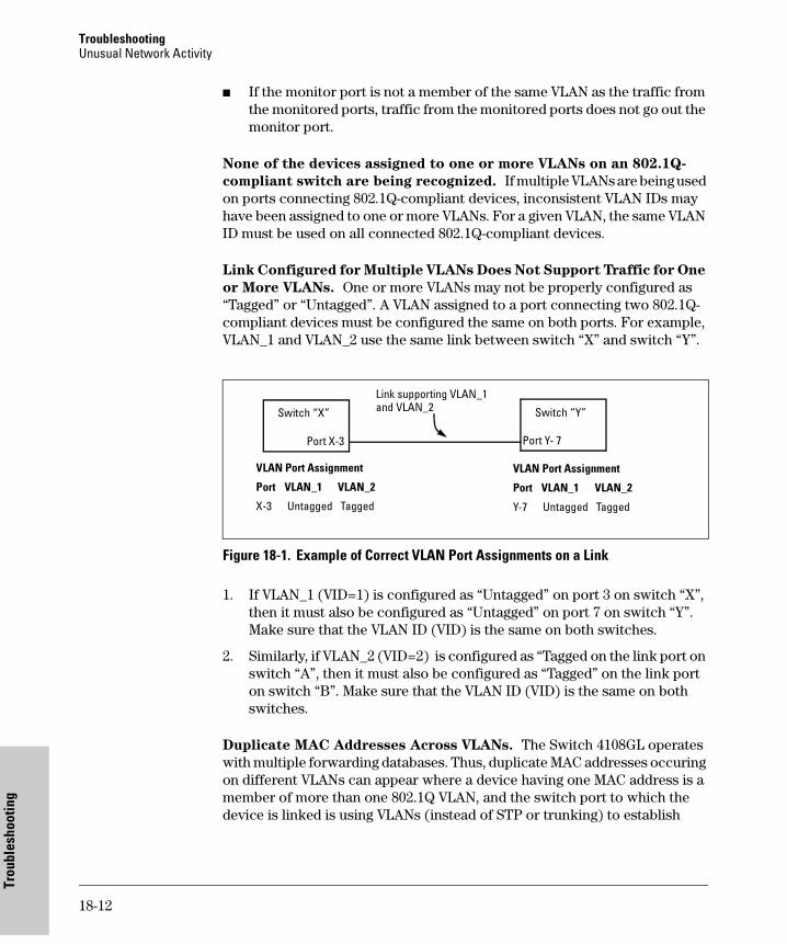
TroubleshootingUnusual Network Activity
Trou
bles
hoot
ing
� If the monitor port is not a member of the same VLAN as the traffic from the monitored ports, traffic from the monitored ports does not go out the monitor port.
None of the devices assigned to one or more VLANs on an 802.1Q-
compliant switch are being recognized. If multiple VLANs are being used on ports connecting 802.1Q-compliant devices, inconsistent VLAN IDs may have been assigned to one or more VLANs. For a given VLAN, the same VLAN ID must be used on all connected 802.1Q-compliant devices.
Link Configured for Multiple VLANs Does Not Support Traffic for One
or More VLANs. One or more VLANs may not be properly configured as “Tagged” or “Untagged”. A VLAN assigned to a port connecting two 802.1Q-compliant devices must be configured the same on both ports. For example, VLAN_1 and VLAN_2 use the same link between switch “X” and switch “Y”.
Figure 18-1. Example of Correct VLAN Port Assignments on a Link
1. If VLAN_1 (VID=1) is configured as “Untagged” on port 3 on switch “X”, then it must also be configured as “Untagged” on port 7 on switch “Y”. Make sure that the VLAN ID (VID) is the same on both switches.
2. Similarly, if VLAN_2 (VID=2) is configured as “Tagged on the link port on switch “A”, then it must also be configured as “Tagged” on the link port on switch “B”. Make sure that the VLAN ID (VID) is the same on both switches.
Duplicate MAC Addresses Across VLANs. The Switch 4108GL operates with multiple forwarding databases. Thus, duplicate MAC addresses occuring on different VLANs can appear where a device having one MAC address is a member of more than one 802.1Q VLAN, and the switch port to which the device is linked is using VLANs (instead of STP or trunking) to establish
Switch “Y”Switch “X”
Link supporting VLAN_1 and VLAN_2
VLAN Port Assignment
Port VLAN_1 VLAN_2
X-3 Untagged Tagged
Port X-3 Port Y- 7
VLAN Port Assignment
Port VLAN_1 VLAN_2
Y-7 Untagged Tagged
18-12
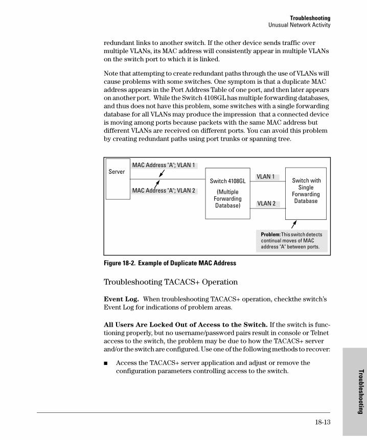
TroubleshootingUnusual Network Activity
Troubleshootin
redundant links to another switch. If the other device sends traffic over multiple VLANs, its MAC address will consistently appear in multiple VLANs on the switch port to which it is linked.
Note that attempting to create redundant paths through the use of VLANs will cause problems with some switches. One symptom is that a duplicate MAC address appears in the Port Address Table of one port, and then later appears on another port. While the Switch 4108GL has multiple forwarding databases, and thus does not have this problem, some switches with a single forwarding database for all VLANs may produce the impression that a connected device is moving among ports because packets with the same MAC address but different VLANs are received on different ports. You can avoid this problem by creating redundant paths using port trunks or spanning tree.
Figure 18-2. Example of Duplicate MAC Address
Troubleshooting TACACS+ Operation
Event Log. When troubleshooting TACACS+ operation, checkthe switch’s Event Log for indications of problem areas.
All Users Are Locked Out of Access to the Switch. If the switch is func-tioning properly, but no username/password pairs result in console or Telnet access to the switch, the problem may be due to how the TACACS+ server and/or the switch are configured. Use one of the following methods to recover:
� Access the TACACS+ server application and adjust or remove the configuration parameters controlling access to the switch.
ServerSwitch 4108GL
(Multiple Forwarding Database)
Switch with Single
Forwarding Database
MAC Address "A"; VLAN 1
MAC Address "A"; VLAN 2
Problem: This switch detects continual moves of MAC address "A" between ports.
VLAN 1
VLAN 2
18-13
g

TroubleshootingUnusual Network Activity
Trou
bles
hoot
ing
� If the above method does not work, try eliminating configuration changes in the switch that have not been saved to flash (boot-up configuration) by causing the switch to reboot from the boot-up configuration (which includes only the configuration changes made prior to the last write memory command.) If you did not use write memory to save the authentication configuration to flash, then pressing the Reset button or cycling the power reboots the switch with the boot-up configuration.
� Disconnect the switch from network access to any TACACS+ servers and then log in to the switch using either Telnet or direct console port access. Because the switch cannot access a TACACS+ server, it will default to local authentication. You can then use the switch’s local Operator or Manager username/password pair to log on.
� As a last resort, use the Clear/Reset button combination to reset the switch to its factory default boot-up configuration. Taking this step means you will have to reconfigure the switch to return it to operation in your network.
No Communication Between the Switch and the TACACS+ Server
Application. If the switch can access the server device (that is, it can ping the server), then a configuration error may be the problem. Some possiblities include:
� The server IP address configured with the switch’s tacacs-server host command may not be correct. (Use the switch’s show tacacs-server command to list the TACACS+ server IP address.)
� The encryption key configured in the server does not match the encryption key configured in the switch (by using the tacacs-server key command). Verify the key in the server and compare it to the key configured in the switch. (Use show tacacs-server to list the global key. Use show config or show config running to list any server-specific keys.)
� The accessible TACACS+ servers are not configured to provide service to the switch.
Access Is Denied Even Though the Username/Password Pair Is
Correct. Some reasons for denial include the following parameters controlled by your TACACS+ server application:
� The account has expired.
� The access attempt is through a port that is not allowed for the account.
18-14
TroubleshootingUnusual Network Activity
Troubleshootin
� The time quota for the account has been exhausted.
� The time credit for the account has expired.
� The access attempt is outside of the timeframe allowed for the account.
� The allowed number of concurrent logins for the account has been exceeded
For more help, refer to the documentation provided with your TACACS+ server application.
Unknown Users Allowed to Login to the Switch. Your TACACS+ appli-cation may be configured to allow access to unknown users by assigning them the privileges included in a default user profile. Refer to the documentation provided with your TACACS+ server application.
System Allows Fewer Login Attempts than Specified in the Switch
Configuration. Your TACACS+ server application may be configured to allow fewer login attempts than you have configured in the switch with the aaa authentication num-attempts command.
18-15
g
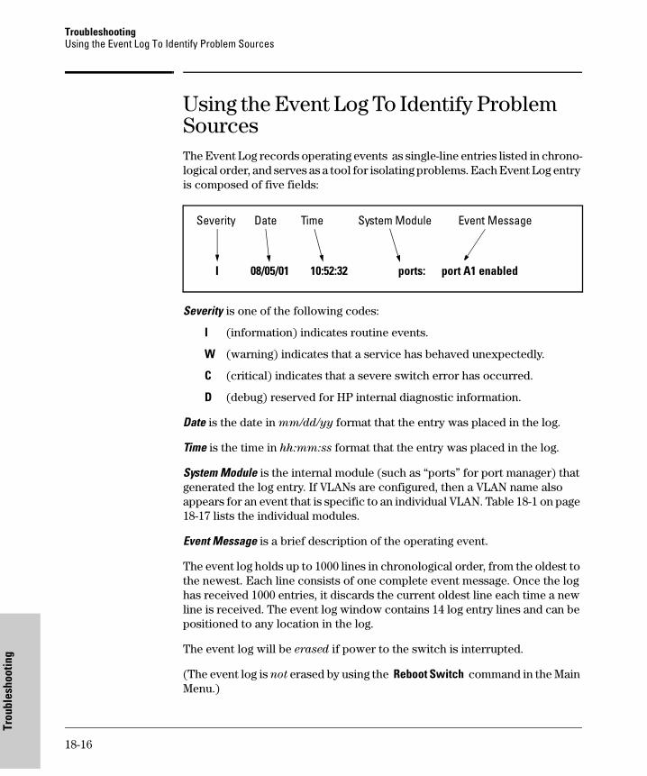
TroubleshootingUsing the Event Log To Identify Problem Sources
Trou
bles
hoot
ing
Using the Event Log To Identify Problem SourcesThe Event Log records operating events as single-line entries listed in chrono-logical order, and serves as a tool for isolating problems. Each Event Log entry is composed of five fields:
Severity is one of the following codes:
I (information) indicates routine events.
W (warning) indicates that a service has behaved unexpectedly.
C (critical) indicates that a severe switch error has occurred.
D (debug) reserved for HP internal diagnostic information.
Date is the date in mm/dd/yy format that the entry was placed in the log.
Time is the time in hh:mm:ss format that the entry was placed in the log.
System Module is the internal module (such as “ports” for port manager) that generated the log entry. If VLANs are configured, then a VLAN name also appears for an event that is specific to an individual VLAN. Table 18-1 on page 18-17 lists the individual modules.
Event Message is a brief description of the operating event.
The event log holds up to 1000 lines in chronological order, from the oldest to the newest. Each line consists of one complete event message. Once the log has received 1000 entries, it discards the current oldest line each time a new line is received. The event log window contains 14 log entry lines and can be positioned to any location in the log.
The event log will be erased if power to the switch is interrupted.
(The event log is not erased by using the Reboot Switch command in the Main Menu.)
Severity Date Time System Module Event Message
I 08/05/01 10:52:32 ports: port A1 enabled
18-16
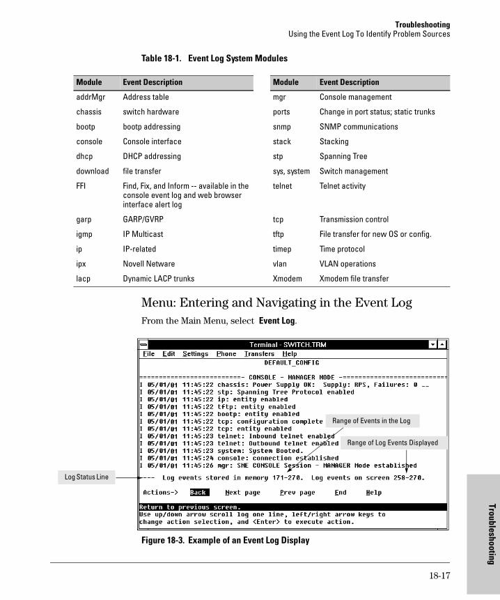
TroubleshootingUsing the Event Log To Identify Problem Sources
Troubleshootin
Table 18-1. Event Log System Modules
Menu: Entering and Navigating in the Event Log From the Main Menu, select Event Log.
Figure 18-3. Example of an Event Log Display
Module Event Description Module Event Description
addrMgr Address table mgr Console management
chassis switch hardware ports Change in port status; static trunks
bootp bootp addressing snmp SNMP communications
console Console interface stack Stacking
dhcp DHCP addressing stp Spanning Tree
download file transfer sys, system Switch management
FFI Find, Fix, and Inform -- available in the console event log and web browser interface alert log
telnet Telnet activity
garp GARP/GVRP tcp Transmission control
igmp IP Multicast tftp File transfer for new OS or config.
ip IP-related timep Time protocol
ipx Novell Netware vlan VLAN operations
lacp Dynamic LACP trunks Xmodem Xmodem file transfer
Range of Events in the Log
Range of Log Events Displayed
Log Status Line
18-17
g
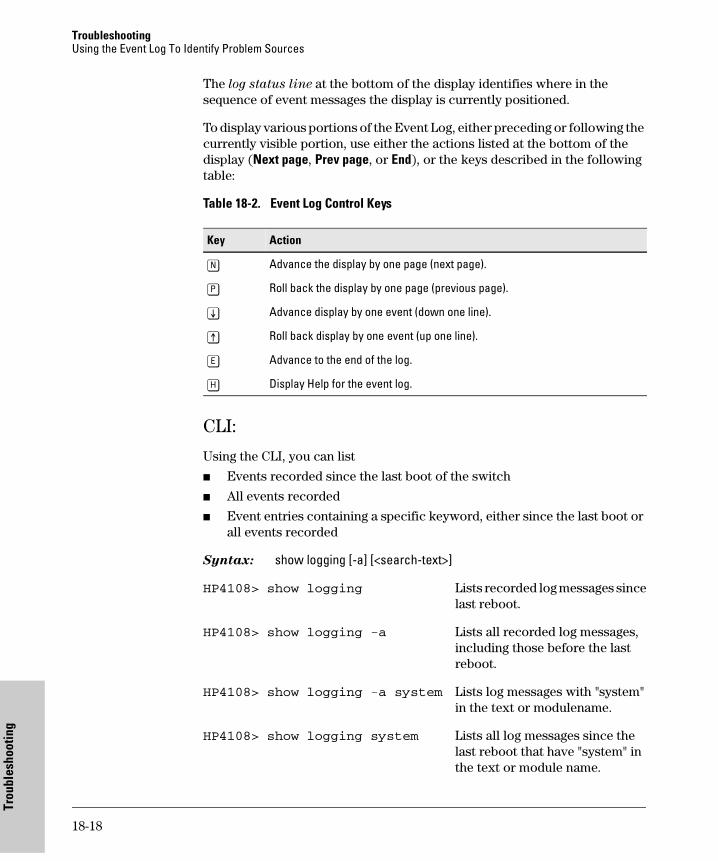
TroubleshootingUsing the Event Log To Identify Problem Sources
Trou
bles
hoot
ing
The log status line at the bottom of the display identifies where in the sequence of event messages the display is currently positioned.
To display various portions of the Event Log, either preceding or following the currently visible portion, use either the actions listed at the bottom of the display (Next page, Prev page, or End), or the keys described in the following table:
Table 18-2. Event Log Control Keys
CLI:
Using the CLI, you can list
� Events recorded since the last boot of the switch
� All events recorded
� Event entries containing a specific keyword, either since the last boot or all events recorded
Syntax: show logging [-a] [<search-text>]
HP4108> show logging Lists recorded log messages sincelast reboot.
HP4108> show logging -a Lists all recorded log messages,including those before the lastreboot.
HP4108> show logging -a system Lists log messages with "system"in the text or modulename.
HP4108> show logging system Lists all log messages since the last reboot that have "system" inthe text or module name.
Key Action
[N] Advance the display by one page (next page).
[P] Roll back the display by one page (previous page).
[v] Advance display by one event (down one line).
[^] Roll back display by one event (up one line).
[E] Advance to the end of the log.
[H] Display Help for the event log.
18-18
TroubleshootingDiagnostic Tools
Troubleshootin
Diagnostic Tools
Diagnostic Features
Port Auto-Negotiation
When a link LED does not light (indicating loss of link between two devices), the most common reason is a failure of port auto-negotiation between the connecting ports. If a link LED fails to light when you connect the switch to a port on another device, do the following:
1. Ensure that the switch port and the port on the attached end-node are both set to Auto mode.
2. If the attached end-node does not have an Auto mode setting, then you must manually configure the switch port to the same setting as the end-node port. See Chapter 11, “Optimizing Port Usage Through Traffic Con-trol and Port Trunking”.
Ping and Link Tests
The Ping test and the Link test are point-to-point tests between your switch and another IEEE 802.3-compliant device on your network. These tests can tell you whether the switch is communicating properly with another device.
Feature Default Menu CLI Web
Port Autonegotiation n/a n/a n/a n/a
PingTest n/a — page 18-22 page 18-21
Link Test n/a — page 18-22 page 18-21
Display Config File n/a — page 18-24 page 18-24
Admin. and Troubleshooting Commands
n/a — page 18-25 —
Factory-Default Config page 18-26(Buttons)
— page 18-26 —
Port Status n/a pages 11-2 and 11-5
pages 11-2 and 11-6
pages 11-2 and 11-5
18-19
g
TroubleshootingDiagnostic Tools
Trou
bles
hoot
ing
N o t e To respond to a Ping test or a Link test, the device you are trying to reach must be IEEE 802.3-compliant.
Ping Test. This is a test of the path between the switch and another device on the same or another IP network that can respond to IP packets (ICMP Echo Requests).
Link Test. This is a test of the connection between the switch and a desig-nated network device on the same LAN (or VLAN, if configured). During the link test, IEEE 802.2 test packets are sent to the designated network device in the same VLAN or broadcast domain. The remote device must be able to respond with an 802.2 Test Response Packet.
18-20
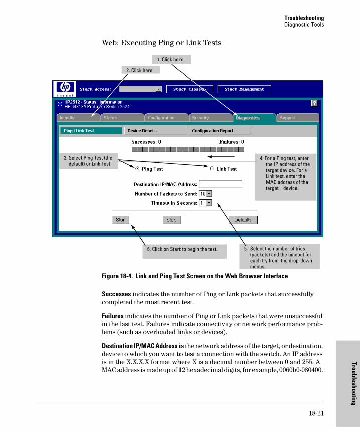
TroubleshootingDiagnostic Tools
Troubleshootin
Web: Executing Ping or Link Tests
Figure 18-4. Link and Ping Test Screen on the Web Browser Interface
Successes indicates the number of Ping or Link packets that successfully completed the most recent test.
Failures indicates the number of Ping or Link packets that were unsuccessful in the last test. Failures indicate connectivity or network performance prob-lems (such as overloaded links or devices).
Destination IP/MAC Address is the network address of the target, or destination, device to which you want to test a connection with the switch. An IP address is in the X.X.X.X format where X is a decimal number between 0 and 255. A MAC address is made up of 12 hexadecimal digits, for example, 0060b0-080400.
4. For a Ping test, enter the IP address of the target device. For a Link test, enter the MAC address of the target device.
3. Select Ping Test (the default) or Link Test
5. Select the number of tries (packets) and the timeout for each try from the drop-down menus.
6. Click on Start to begin the test.
2. Click here.
1. Click here.
18-21
g
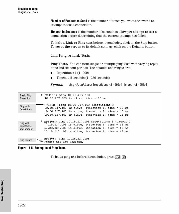
TroubleshootingDiagnostic Tools
Trou
bles
hoot
ing
Number of Packets to Send is the number of times you want the switch to attempt to test a connection.
Timeout in Seconds is the number of seconds to allow per attempt to test a connection before determining that the current attempt has failed.
To halt a Link or Ping test before it concludes, click on the Stop button. To reset the screen to its default settings, click on the Defaults button.
CLI: Ping or Link Tests
Ping Tests. You can issue single or multiple ping tests with varying repiti-tions and timeout periods. The defaults and ranges are:
� Repetitions: 1 (1 - 999)
� Timeout: 5 seconds (1 - 256 seconds)
Syntax: ping <ip-address> [repetitions <1 - 999>] [timeout <1 - 256>]
Figure 18-5. Examples of Ping Tests
To halt a ping test before it concludes, press [Ctrl] [C].
Ping with Repetitions and Timeout
Basic Ping Operation
Ping Failure
Ping with Repetitions
18-22
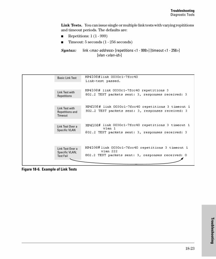
TroubleshootingDiagnostic Tools
Troubleshootin
Link Tests. You can issue single or multiple link tests with varying repititions and timeout periods. The defaults are:
� Repetitions: 1 (1 - 999)
� Timeout: 5 seconds (1 - 256 seconds)
Syntax: link <mac-address> [repetitions <1 - 999>] [timeout <1 - 256>][vlan <vlan-id>]
Figure 18-6. Example of Link Tests
Basic Link Test
Link Test with Repetitions
Link Test with Repetitions and Timeout
Link Test Over a Specific VLAN
Link Test Over a Specific VLAN; Test Fail
18-23
g
TroubleshootingDiagnostic Tools
Trou
bles
hoot
ing
Displaying the Configuration File
The complete switch configuration is contained in a file that you can browse from either the web browser interface or the CLI. It may be useful in some troubleshooting scenarios to view the switch configuration.
CLI: Viewing the Configuration File
Using the CLI, you can display either the running configuration or the startup configuration. (For more on these topics, see appendix C, "Switch Memory and Configuration".)
Syntax: write terminal Displays the running configuration.
show config Displays the startup configuration.
Web: Viewing the Configuration File
To display the running configuration, through the web browser interface:
1. Click on the Diagnostics tab.
2. Click on [Configuration Report]
3. Use the right-side scroll bar to scroll through the configuration listing.
18-24
TroubleshootingDiagnostic Tools
Troubleshootin
CLI Administrative and Troubleshooting Commands
These commands provide information or perform actions that you may find helpful in troubleshooting operating problems with the switch.
N o t e For more on the CLI, refer to chapter 3, "Using the Command Line Reference (CLI).
Syntax: show version Shows the software version currently running on the switch, and the flash image from which theswitch booted (primary or secondary).
show boot-history Displays the switch shutdownhistory.
show history Displays the current command history.
[no] page Toggles the paging mode for display commands between continuous listing and per-page listing.
setup Displays the Switch Setup screenfrom the menu interface
repeat Repeatedly executes the previouscommand until a key is pressed.
kill Terminates all other active sessions.
18-25
g
TroubleshootingRestoring the Factory-Default Configuration
Trou
bles
hoot
ing
Restoring the Factory-Default Configuration
As part of your troubleshooting process, it may become necessary to return the switch configuration to the factory default settings. This process momen-tarily interrupts the switch operation, clears any passwords, clears the console event log, resets the network counters to zero, performs a complete self test, and reboots the switch into its factory default configuration including deleting an IP address. There are two methods for restting to the factory-default configuration:
� CLI
� Clear/Reset button combination
N o t e HP recommends that you save your configuration to a TFTP server before resetting the switch to its factory-default configuration. You can also save your configuration via Xmodem, to a directly connected PC.
CLI: Resetting to the Factory-Default Configuration
This command operates at any level except the Operator level.
Syntax: erase startup-configuration Deletes the startup-config file in flash so that the switch will reboot with its factory-default configuration.
N o t e The erase startup-config command does not clear passwords.
Clear/Reset: Resetting to the Factory-Default Configuration
To execute the factory default reset, perform these steps:
1. Using pointed objects, simultaneously press both the Reset and Clear buttons on the front of the switch.
2. Continue to press the Clear button while releasing the Reset button.
3. When the Self Test LED begins to flash, release the Clear button.
The switch will then complete its self test and begin operating with the configuration restored to the factory default settings.
18-26
TroubleshootingRestoring a Flash Image
Troubleshootin
Restoring a Flash Image
The switch can lose its operating system if either the primary or secondary flash image location is empty or contains a corrupted OS file and an operator uses the erase flash command to erase a good OS image file from the opposite flash location.
To Recover from an Empty or Corrupted Flash State. Use the switch’s console serial port to connect to a workstation or laptop computer that has the following:
� A terminal emulator program with Xmodem capability, such as the Hyper-Terminal program included in Windows PC software.
� A copy of a good OS image file for the switch.
N o t e The following procedure requires the use of Xmodem, and copies an OS image into primary flash only.
This procedure assumes you are using HyperTerminal as your terminal emu-lator. If you use a different terminal emulator, you may need to adapt this procedure to the operation of your particular emulator.
1. Start the terminal emulator program.
2. Ensure that the terminal program is configured as follows:
3. Use the Reset button to reset the switch. The following prompt should then appear in the terminal emulator:
Enter h or ? for help.
=>
� Baud rate: 9600
� No parity
� 8 Bits
� 1 stop bit
� No flow control
18-27
g

TroubleshootingRestoring a Flash Image
Trou
bles
hoot
ing
4. Since the OS file is larage, you can increase the speed of the download by changing the switch console and terminal emulator baud rates to a high speed. For example:
a. Change the switch baud rate to 115,200 Bps.
=> sp 115200
b. Change the terminal emulator baud rate to match the switch speed:i. In HyperTerminal, select Call | Disconnect.ii. Select File | Properties.iii. click on [Configure . . .].iv. Change the baud rate to 115200.v. Click on [OK]. In the next window, click on [OK] again.vi. Select Call | Connectvii. Press [Enter] one or more times to display the => prompt.
5. Start the Console Download utility by typing do at the => prompt and pressing [Enter]:
=> do
6. You will then see this prompt:
7. At the above prompt:
a. Type y (for Yes)
b. Select Transfer | File in HyperTerminal.
c. Enter the appropriate filename and path for the OS image.
d. Select the Xmodem protocol (and not the 1k Xmodem protocol).
e. Click on [Send].
If you are using HyperTerminal, you will see a screen similar to the following to indicate that the download is in progress:
18-28
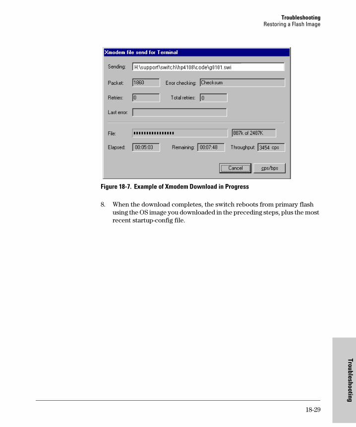
TroubleshootingRestoring a Flash Image
Troubleshootin
Figure 18-7. Example of Xmodem Download in Progress
8. When the download completes, the switch reboots from primary flash using the OS image you downloaded in the preceding steps, plus the most recent startup-config file.
18-29
g

TroubleshootingRestoring a Flash Image
Trou
bles
hoot
ing
18-30
File Transfers
A
File Transfers
Contents
Overview . . . . . . . . . . . . . . . . . . . . . . . . . . . . . . . . . . . . . . . . . . . . . . . . . . . . A-2
Downloading an Operating System (OS) . . . . . . . . . . . . . . . . . . . . . . . A-2
General OS Download Rules . . . . . . . . . . . . . . . . . . . . . . . . . . . . . . . . . A-2
Using TFTP To Download an OS Image from a Server . . . . . . . . . . . A-3Menu: TFTP Download from a Server to Primary Flash . . . . . . . A-4CLI: TFTP Download from a Server to Primary or Secondary Flash . . . . . . . . . . . . . . . . . . . . . . . . . . . . . . . . . . . . . . . . A-5
Using Xmodem to Download an OS Image From a PC or UNIX Workstation . . . . . . . . . . . . . . . . . . . . . . . . . . . . . . . . . . . . . . . . . . . . . . . A-6
Menu: Xmodem Download to Primary Flash . . . . . . . . . . . . . . . . A-7CLI: Xmodem Download from a PC or Unix Workstation to Primary or Secondary Flash . . . . . . . . . . . . . . . . . . . . . . . . . . . . A-8
Switch-to-Switch Download . . . . . . . . . . . . . . . . . . . . . . . . . . . . . . . . . A-9Menu: Switch-to-Switch Download to Primary Flash . . . . . . . . . A-9CLI: Switch-To-Switch Downloads . . . . . . . . . . . . . . . . . . . . . . . A-10
Using the HP TopTools for Hubs & Switches Utility . . . . . . . . . . . . A-11
Troubleshooting TFTP Downloads . . . . . . . . . . . . . . . . . . . . . . . . . . . A-12
Transferring Switch Configurations . . . . . . . . . . . . . . . . . . . . . . . . . . A-13
Copying Diagnostic Data to a Remote Host, PC, or
Unix Workstation . . . . . . . . . . . . . . . . . . . . . . . . . . . . . . . . . . . . . . . . . . . A-16Copying Command Output to a Destination Device . . . . . . . . . A-16Copying Event Log Output to a Destination Device . . . . . . . . . A-17Copying Crash Data Content to a Destination Device . . . . . . . A-17Copying Crash Log Data Content to a Destination Device . . . . A-18
A-1
File TransfersOverview
File
Tra
nsfe
rs
OverviewYou can download new switch software (operating system—OS) and upload or download switch configuration files. These features are useful for acquiring periodic switch software upgrades and for storing or retrieving a switch configuration.
This appendix includes the following information:
� Downloading an operating system (begins below)
� Transferring switch configurations (begins on page A-13)
For information on how switch memory operates, including primary and secondary flash, see Chapter 5, “Switch Memory and Configuration”.
Downloading an Operating System (OS)HP periodically provides switch operating system (OS) updates through the HP Procurve website (http://www.hp.com/go/hpprocurve). For more informa-tion, see the support and warranty booklet shipped with the switch. After you acquire a new OS file, you can use one of the following methods for down-loading the operating system (OS) code to the switch:
OS Download Features
General OS Download Rules
� An OS image you download via the menu interface always goes to primary flash.
� After an OS download, you must reboot the switch to implement the newly downloaded OS. Until a reboot occurs, the switch continues to run on the OS it was using before the download commenced.
Feature Default Menu CLI Web
TFTP n/a page A-4 page A-5 —
Xmodem n/a page A-7 page A-8 —
Switch-to-Switch n/a page A-9 page A-10
SNMP Download Manager in HP TopTools for Hubs & Switches
Refer to the documentation provided with HP TopTools for Hubs and Switches
A-2
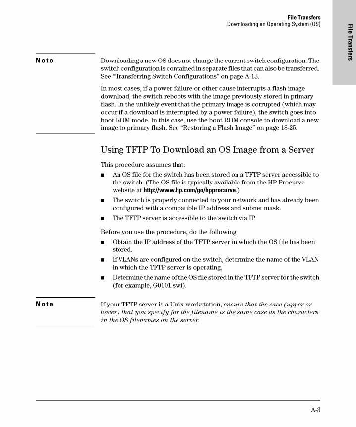
File TransfersDownloading an Operating System (OS) File Transfers
N o t e Downloading a new OS does not change the current switch configuration. The switch configuration is contained in separate files that can also be transferred. See “Transferring Switch Configurations” on page A-13.
In most cases, if a power failure or other cause interrupts a flash image download, the switch reboots with the image previously stored in primary flash. In the unlikely event that the primary image is corrupted (which may occur if a download is interrupted by a power failure), the switch goes into boot ROM mode. In this case, use the boot ROM console to download a new image to primary flash. See “Restoring a Flash Image” on page 18-25.
Using TFTP To Download an OS Image from a Server
This procedure assumes that:
� An OS file for the switch has been stored on a TFTP server accessible to the switch. (The OS file is typically available from the HP Procurve website at http://www.hp.com/go/hpprocurve.)
� The switch is properly connected to your network and has already been configured with a compatible IP address and subnet mask.
� The TFTP server is accessible to the switch via IP.
Before you use the procedure, do the following:
� Obtain the IP address of the TFTP server in which the OS file has been stored.
� If VLANs are configured on the switch, determine the name of the VLAN in which the TFTP server is operating.
� Determine the name of the OS file stored in the TFTP server for the switch (for example, G0101.swi).
N o t e If your TFTP server is a Unix workstation, ensure that the case (upper or
lower) that you specify for the filename is the same case as the characters
in the OS filenames on the server.
A-3
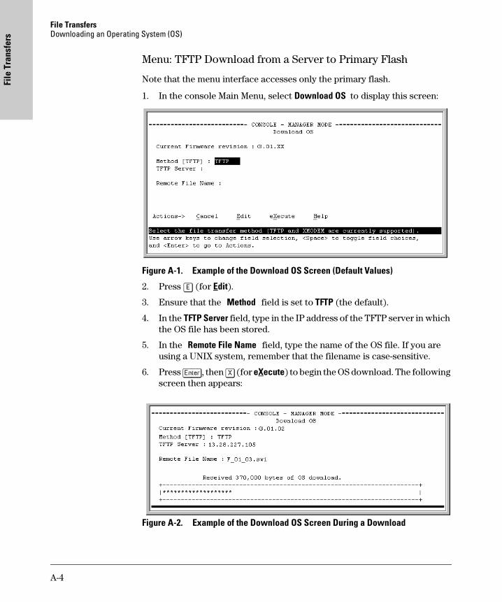
File TransfersDownloading an Operating System (OS)
File
Tra
nsfe
rs
Menu: TFTP Download from a Server to Primary Flash
Note that the menu interface accesses only the primary flash.
1. In the console Main Menu, select Download OS to display this screen:
Figure A-1. Example of the Download OS Screen (Default Values)
2. Press [E] (for Edit).
3. Ensure that the Method field is set to TFTP (the default).
4. In the TFTP Server field, type in the IP address of the TFTP server in which the OS file has been stored.
5. In the Remote File Name field, type the name of the OS file. If you are using a UNIX system, remember that the filename is case-sensitive.
6. Press [Enter], then [X] (for eXecute) to begin the OS download. The following screen then appears:
Figure A-2. Example of the Download OS Screen During a Download
A-4
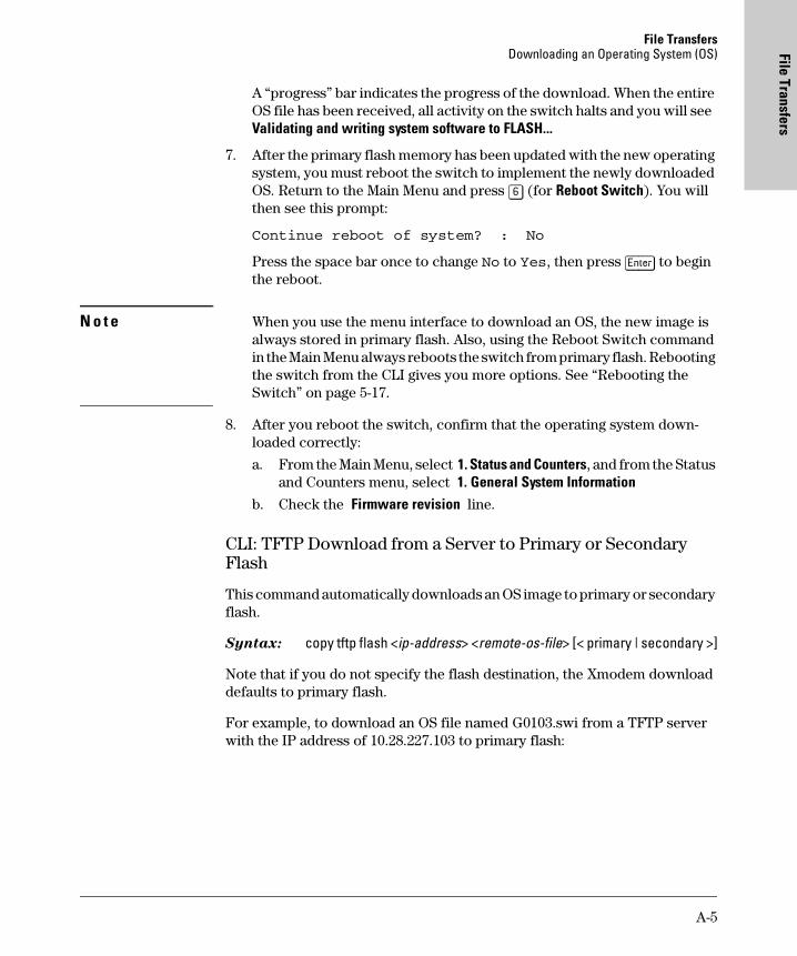
File TransfersDownloading an Operating System (OS) File Transfers
A “progress” bar indicates the progress of the download. When the entire OS file has been received, all activity on the switch halts and you will see Validating and writing system software to FLASH...
7. After the primary flash memory has been updated with the new operating system, you must reboot the switch to implement the newly downloaded OS. Return to the Main Menu and press [6] (for Reboot Switch). You will then see this prompt:
Continue reboot of system? : No
Press the space bar once to change No to Yes, then press [Enter] to begin the reboot.
N o t e When you use the menu interface to download an OS, the new image is always stored in primary flash. Also, using the Reboot Switch command in the Main Menu always reboots the switch from primary flash. Rebooting the switch from the CLI gives you more options. See “Rebooting the Switch” on page 5-17.
8. After you reboot the switch, confirm that the operating system down-loaded correctly:
a. From the Main Menu, select 1. Status and Counters, and from the Status and Counters menu, select 1. General System Information
b. Check the Firmware revision line.
CLI: TFTP Download from a Server to Primary or Secondary Flash
This command automatically downloads an OS image to primary or secondary flash.
Syntax: copy tftp flash <ip-address> <remote-os-file> [< primary | secondary >]
Note that if you do not specify the flash destination, the Xmodem download defaults to primary flash.
For example, to download an OS file named G0103.swi from a TFTP server with the IP address of 10.28.227.103 to primary flash:
A-5
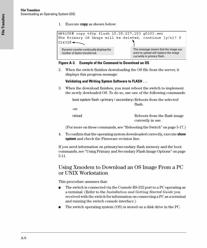
File TransfersDownloading an Operating System (OS)
File
Tra
nsfe
rs
1. Execute copy as shown below:
Figure A-3. Example of the Command to Download an OS
2. When the switch finishes downloading the OS file from the server, it displays this progress message:
Validating and Writing System Software to FLASH . . .
3. When the download finishes, you must reboot the switch to implement the newly dowloaded OS. To do so, use one of the following commands:
boot system flash <primary | secondary>Reboots from the selectedflash.
-or-
reload Reboots from the flash imagecurrently in use.
(For more on these commands, see “Rebooting the Switch” on page 5-17.)
4. To confirm that the operating system downloaded correctly, execute show system and check the Firmware revision line.
If you need information on primary/secondary flash memory and the boot commands, see “Using Primary and Secondary Flash Image Options” on page 5-11.
Using Xmodem to Download an OS Image From a PC or UNIX Workstation
This procedure assumes that:
� The switch is connected via the Console RS-232 port to a PC operating as a terminal. (Refer to the Installation and Getting Started Guide you received with the switch for information on connecting a PC as a terminal and running the switch console interface.)
� The switch operating system (OS) is stored on a disk drive in the PC.
Dynamic counter continually displays the number of bytes transferred.
This message means that the image you want to upload will replace the image currently in primary flash.
A-6
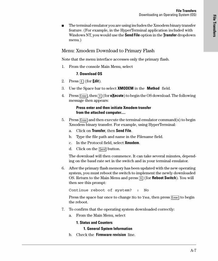
File TransfersDownloading an Operating System (OS) File Transfers
� The terminal emulator you are using includes the Xmodem binary transfer feature. (For example, in the HyperTerminal application included with Windows NT, you would use the Send File option in the Transfer dropdown menu.)
Menu: Xmodem Download to Primary Flash
Note that the menu interface accesses only the primary flash.
1. From the console Main Menu, select
7. Download OS
2. Press [E] (for Edit).
3. Use the Space bar to select XMODEM in the Method field.
4. Press [Enter], then [X] (for eXecute) to begin the OS download. The following message then appears:
Press enter and then initiate Xmodem transferfrom the attached computer.....
5. Press [Enter] and then execute the terminal emulator command(s) to begin Xmodem binary transfer. For example, using HyperTerminal:
a. Click on Transfer, then Send File.
b. Type the file path and name in the Filename field.
c. In the Protocol field, select Xmodem.
d. Click on the [Send] button.
The download will then commence. It can take several minutes, depend-ing on the baud rate set in the switch and in your terminal emulator.
6. After the primary flash memory has been updated with the new operating system, you must reboot the switch to implement the newly downloaded OS. Return to the Main Menu and press [6] (for Reboot Switch). You will then see this prompt:
Continue reboot of system? : No
Press the space bar once to change No to Yes, then press [Enter] to begin the reboot.
7. To confirm that the operating system downloaded correctly:
a. From the Main Menu, select
1. Status and Counters
1. General System Informationb. Check the Firmware revision line.
A-7
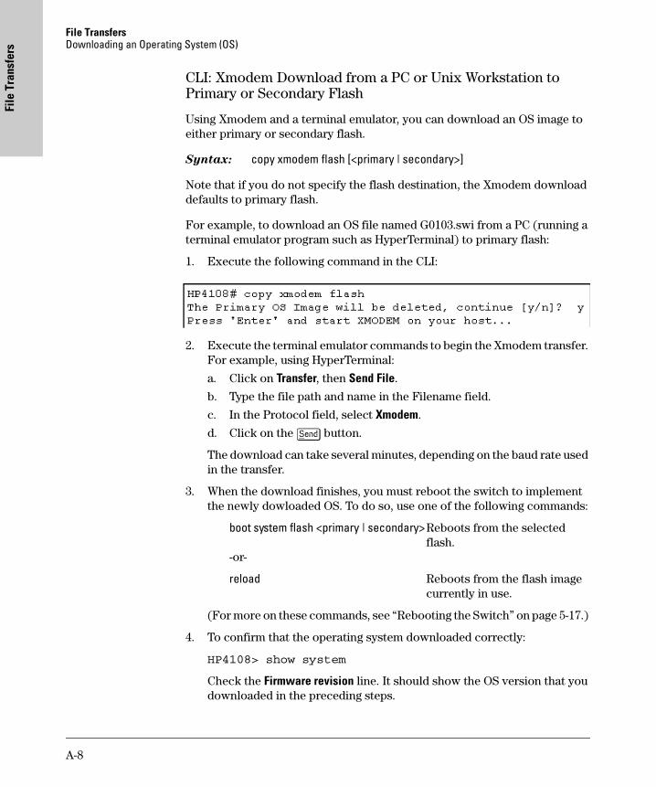
File TransfersDownloading an Operating System (OS)
File
Tra
nsfe
rs
CLI: Xmodem Download from a PC or Unix Workstation to Primary or Secondary Flash
Using Xmodem and a terminal emulator, you can download an OS image to either primary or secondary flash.
Syntax: copy xmodem flash [<primary | secondary>]
Note that if you do not specify the flash destination, the Xmodem download defaults to primary flash.
For example, to download an OS file named G0103.swi from a PC (running a terminal emulator program such as HyperTerminal) to primary flash:
1. Execute the following command in the CLI:
2. Execute the terminal emulator commands to begin the Xmodem transfer. For example, using HyperTerminal:
a. Click on Transfer, then Send File.
b. Type the file path and name in the Filename field.
c. In the Protocol field, select Xmodem.
d. Click on the [Send] button.
The download can take several minutes, depending on the baud rate used in the transfer.
3. When the download finishes, you must reboot the switch to implement the newly dowloaded OS. To do so, use one of the following commands:
boot system flash <primary | secondary>Reboots from the selectedflash.
-or-
reload Reboots from the flash imagecurrently in use.
(For more on these commands, see “Rebooting the Switch” on page 5-17.)
4. To confirm that the operating system downloaded correctly:
HP4108> show system
Check the Firmware revision line. It should show the OS version that you downloaded in the preceding steps.
A-8
File TransfersDownloading an Operating System (OS) File Transfers
If you need information on primary/secondary flash memory and the boot commands, see “Using Primary and Secondary Flash Image Options” on page 5-11.
Switch-to-Switch Download
You can use TFTP to transfer an OS image between two Switch 4108GLs. The menu interface enables you to transfer primary-to-primary or secondary-to-primary. The CLI enables all combinations of flash location options.
Menu: Switch-to-Switch Download to Primary Flash
Using the menu interface, you can download an OS from either the primary or secondary flash of one Switch 4108GL to the primary flash of another Switch 4108GL.
1. From the switch console Main Menu in the switch to receive the down-load, select 7. Download OS screen.
2. Ensure that the Method parameter is set to TFTP (the default).
3. In the TFTP Server field, enter the IP address of the remote Switch 4108GL containing the OS you want to download.
4. For the Remote File Name, enter one of the following:
• To download the OS in the primary flash of the source switch, type “flash” in lowercase characters.
• To download the OS in the secondary flash of the source switch, type /os/secondary.
5. Press [Enter], then [X] (for eXecute) to begin the OS download.
6. A “progress” bar indicates the progress of the download. When the entire operating system has been received, all activity on the switch halts and the following messages appear:
Validating and writing system software to FLASH...
7. After the primary flash memory has been updated with the new operating system, you must reboot the switch to implement the newly downloaded OS. Return to the Main Menu and press [6] (for Reboot Switch). You will then see this prompt:
Continue reboot of system? : No
Press the space bar once to change No to Yes, then press [Enter] to begin the reboot.
8. To confirm that the operating system downloaded correctly:
A-9
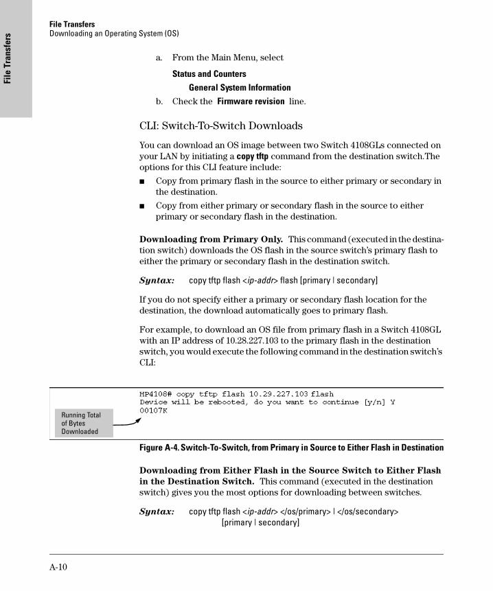
File TransfersDownloading an Operating System (OS)
File
Tra
nsfe
rs
a. From the Main Menu, select
Status and Counters
General System Informationb. Check the Firmware revision line.
CLI: Switch-To-Switch Downloads
You can download an OS image between two Switch 4108GLs connected on your LAN by initiating a copy tftp command from the destination switch.The options for this CLI feature include:
� Copy from primary flash in the source to either primary or secondary in the destination.
� Copy from either primary or secondary flash in the source to either primary or secondary flash in the destination.
Downloading from Primary Only. This command (executed in the destina-tion switch) downloads the OS flash in the source switch’s primary flash to either the primary or secondary flash in the destination switch.
Syntax: copy tftp flash <ip-addr> flash [primary | secondary]
If you do not specify either a primary or secondary flash location for the destination, the download automatically goes to primary flash.
For example, to download an OS file from primary flash in a Switch 4108GL with an IP address of 10.28.227.103 to the primary flash in the destination switch, you would execute the following command in the destination switch’s CLI:
Figure A-4. Switch-To-Switch, from Primary in Source to Either Flash in Destination
Downloading from Either Flash in the Source Switch to Either Flash
in the Destination Switch. This command (executed in the destination switch) gives you the most options for downloading between switches.
Syntax: copy tftp flash <ip-addr> </os/primary> | </os/secondary>[primary | secondary]
Running Total of Bytes Downloaded
A-10
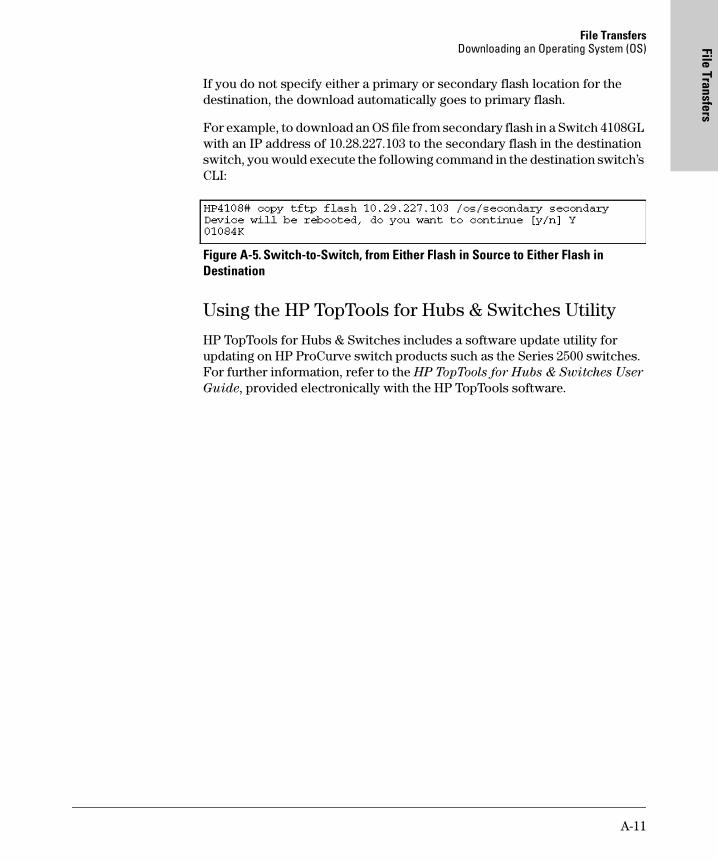
File TransfersDownloading an Operating System (OS) File Transfers
If you do not specify either a primary or secondary flash location for the destination, the download automatically goes to primary flash.
For example, to download an OS file from secondary flash in a Switch 4108GL with an IP address of 10.28.227.103 to the secondary flash in the destination switch, you would execute the following command in the destination switch’s CLI:
Figure A-5. Switch-to-Switch, from Either Flash in Source to Either Flash in Destination
Using the HP TopTools for Hubs & Switches Utility
HP TopTools for Hubs & Switches includes a software update utility for updating on HP ProCurve switch products such as the Series 2500 switches. For further information, refer to the HP TopTools for Hubs & Switches User
Guide, provided electronically with the HP TopTools software.
A-11
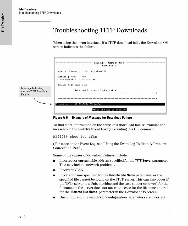
File TransfersTroubleshooting TFTP Downloads
File
Tra
nsfe
rs
Troubleshooting TFTP Downloads
When using the menu interface, if a TFTP download fails, the Download OS screen indicates the failure.
Figure A-6. Example of Message for Download Failure
To find more information on the cause of a download failure, examine the messages in the switch’s Event Log by executing this CLI command:
HP4108# show log tftp
(For more on the Event Log, see “Using the Event Log To Identify Problem Sources” on 18-16.)
Some of the causes of download failures include:
� Incorrect or unreachable address specified for the TFTP Server parameter. This may include network problems.
� Incorrect VLAN.
� Incorrect name specified for the Remote File Name parameter, or the specified file cannot be found on the TFTP server. This can also occur if the TFTP server is a Unix machine and the case (upper or lower) for the filename on the server does not match the case for the filename entered for the Remote File Name parameter in the Download OS screen.
� One or more of the switch’s IP configuration parameters are incorrect.
Message Indicating cause of TFTP Download Failure
A-12
File TransfersTransferring Switch Configurations File Transfers
� For a Unix TFTP server, the file permissions for the OS file do not allow the file to be copied.
� Another console session (through either a direct connection to a terminal device or through Telnet) was already running when you started the session in which the download was attempted.
N o t e If an error occurs in which normal switch operation cannot be restored, the switch automatically reboots itself. In this case, an appropriate message is displayed after the switch reboots.
Transferring Switch Configurations
Transfer Features
Using the CLI commands described in this section, you can copy switch configurations to and from a switch.
TFTP: Copying a Configuration from a Remote Host.
Syntax: copy tftp <startup-config | running-config><ip-address> <remote-file>
This command copies a configuration from a remote host to the startup-config file in the switch. (See Chapter 5, “Using Primary and Secondary Flash Image Options” for information on the startup-config file.)
For example, to download a configuration file named sw4108 in the configs directory on drive "d" in a remote host having an IP address of 10.28.227.105:
Switch 4108GL# copy tftp startup-config 10.28.227.105
d:\configs\sw2512
Feature Default Menu CLI Web
use TFTP to copy from a remote host to a config file
n/a — below
use TFTP to copy a config file to a remote host
n/a — page A-14
use Xmodem to copy a configuration from a serially connected host to a config file
n/a — page A-14
Use Xmodem to copy a config file to a serially connected host
n/a — page A-15
A-13
File TransfersTransferring Switch Configurations
File
Tra
nsfe
rs
TFTP: Copying a Configuration File to a Remote Host.
Syntax: copy <startup-config | running-config> tftp <ip-addr> <remote-file>
This command copies the switch’s startup configuration (startup-config file) to a remote TFTP host.
For example, to upload the current startup configuration to a file named sw4108 in the configs directory on drive "d" in a remote host having an IP address of 10.28.227.105:
HP4108# copy startup-config tftp 10.28.227.105
d:\configs\sw2512
Xmodem: Copying a Configuration File from the Switch to a Serially
Connected PC or Unix Workstation. To use this method, the switch must be connected via the serial port to a PC or Unix workstation to which you want to copy the configuration file. You will need to:
� Determine a filename to use.
� Know the directory path you will use to store the the configuration file.
Syntax: copy <startup-config | running-config> xmodem <pc | unix>
For example, to copy a configuration file to a PC serially connected to the switch:
1. Determine the file name and directory location on the PC.
2. Execute the following command:
3. After you see the above prompt, press [Enter].
4. Execute the terminal emulator commands to begin the file transfer.
A-14
File TransfersTransferring Switch Configurations File Transfers
Xmodem: Copying a Configuration File from a Serially Connected PC
or Unix Workstation. To use this method, the switch must be connected via the serial port to a PC or Unix workstation on which is stored the configuration file you want to copy. To complete the copying, you will need to know the name of the file to copy and the drive and directory location of the file.
Syntax: copy xmodem startup-config <pc | unix>
For example, to copy a configuration file from a PC serially connected to the switch:
1. Execute the following command:
2. After you see the above prompt, press [Enter].
3. Execute the terminal emulator commands to begin the file transfer.
4. When the download finishes, you must reboot the switch to implement the newly dowloaded OS. To do so, use one of the following commands:
boot system flash <primary | secondary>Reboots from the selectedflash.
-or-
reload Reboots from the flash imagecurrently in use.
(For more on these commands, see “Rebooting the Switch” on page 5-17.)
A-15
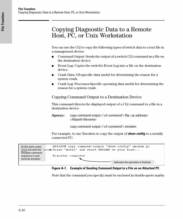
File TransfersCopying Diagnostic Data to a Remote Host, PC, or Unix Workstation
File
Tra
nsfe
rs
Copying Diagnostic Data to a Remote Host, PC, or Unix Workstation
You can use the CLI to copy the following types of switch data to a text file in a management device:
� Command Output: Sends the output of a switch CLI command as a file on the destination device.
� Event Log: Copies the switch’s Event Log into a file on the destination device.
� Crash Data: OS-specific data useful for determining the reason for a system crash.
� Crash Log: Processor-Specific operating data useful for determining the reason for a system crash.
Copying Command Output to a Destination Device
This command directs the displayed output of a CLI command to a file in a destination device.
Syntax: copy command-output <"cli-command"> tftp <ip-address> <filepath-filename>
copy command-output <"cli-command"> xmodem
For example, to use Xmodem to copy the output of show config to a serially connected PC:
Figure A-7. Example of Sending Command Output to a File on an Attached PC
Note that the command you specify must be enclosed in double-quote marks.
At this point, press [Enter] and start the Xmodem command sequence in your terminal emulator.
Indicates the operation is finished.
A-16
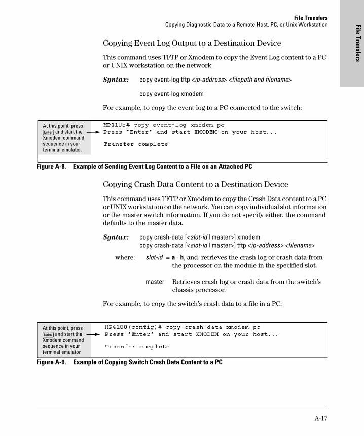
File TransfersCopying Diagnostic Data to a Remote Host, PC, or Unix Workstation File Transfers
Copying Event Log Output to a Destination Device
This command uses TFTP or Xmodem to copy the Event Log content to a PC or UNIX workstation on the network.
Syntax: copy event-log tftp <ip-address> <filepath and filename>
copy event-log xmodem
For example, to copy the event log to a PC connected to the switch:
Figure A-8. Example of Sending Event Log Content to a File on an Attached PC
Copying Crash Data Content to a Destination Device
This command uses TFTP or Xmodem to copy the Crash Data content to a PC or UNIX workstation on the network. You can copy individual slot information or the master switch information. If you do not specify either, the command defaults to the master data.
Syntax: copy crash-data [<slot-id | master>] xmodem copy crash-data [<slot-id | master>] tftp <ip-address> <filename>
where: slot-id = a - h, and retrieves the crash log or crash data fromthe processor on the module in the specified slot.
master Retrieves crash log or crash data from the switch’s chassis processor.
For example, to copy the switch’s crash data to a file in a PC:
Figure A-9. Example of Copying Switch Crash Data Content to a PC
At this point, press [Enter] and start the Xmodem command sequence in your terminal emulator.
At this point, press [Enter] and start the Xmodem command sequence in your terminal emulator.
A-17

File TransfersCopying Diagnostic Data to a Remote Host, PC, or Unix Workstation
File
Tra
nsfe
rs
Copying Crash Log Data Content to a Destination Device
This command uses TFTP or Xmodem to copy the Crash Log content to a PC or UNIX workstation on the network. You can copy individual slot information or the master switch information. If you do not specify either, the command defaults to the master data.
Syntax: copy crash-log [<slot-id | master>] tftp <ip-address> <filepath and filename>
copy crash-log [<slot-id | master>] xmodem
where: slot-id = a - h, and retrieves the crash log or crash data fromthe processor on the module in the specified slot.
master Retrieves crash log or crash data from the switch’s chassis processor.
For example, to copy the Crash Log for slot C to a file in a PC connected to the switch:
Figure A-10. Example of sending a Crash Log for Slot C to a File on an Attached PC
At this point, press [Enter] and start the Xmodem command sequence in your terminal emulator.
A-18
MA
C Address M
anagement
B
MAC Address Management
Contents
Overview . . . . . . . . . . . . . . . . . . . . . . . . . . . . . . . . . . . . . . . . . . . . . . . . . . . . . B-1
Determining MAC Addresses . . . . . . . . . . . . . . . . . . . . . . . . . . . . . . . . . . B-2
Menu: Viewing the Switch’s MAC Addresses . . . . . . . . . . . . . . . . . . . . . B-3
CLI: Viewing the Port and VLAN MAC Addresses . . . . . . . . . . . . . . . . B-4
Overview
The switch assigns MAC addresses in these areas:
� For management functions:
• One Base MAC address assigned to the default VLAN (VID = 1)
• Additional MAC address(es) corresponding to additional VLANs you configure in the switch
� For internal switch operations: One MAC address per port (See "CLI: Viewing the Port and VLAN MAC Addresses" on page B-4.)
MAC addresses are assigned at the factory. The switch automatically implements these addresses for VLANs and ports as they are added to the switch.
N o t e The switch’s base MAC address is also printed on a label affixed to the back of the switch.
B-1
MAC Address ManagementDetermining MAC Addresses
MA
C A
ddre
ss M
anag
emen
t
Determining MAC Addresses
MAC Address Viewing Methods
� Use the menu interface to view the switch’s base MAC address and the MAC address assigned to any non-default VLAN you have configured on the switch.
N o t e The switch’s base MAC address is used for the default VLAN (VID = 1) that is always available on the switch.
� Use the CLI to view the switch’s port MAC addresses in hexadecimal format.
Feature Default Menu CLI Web
view switch’s base (default vlan) MAC address and the addressing for any added VLANs
n/a B-3 B-4 —
view port MAC addresses (hexadecimal format) n/a — B-4 —
B-2
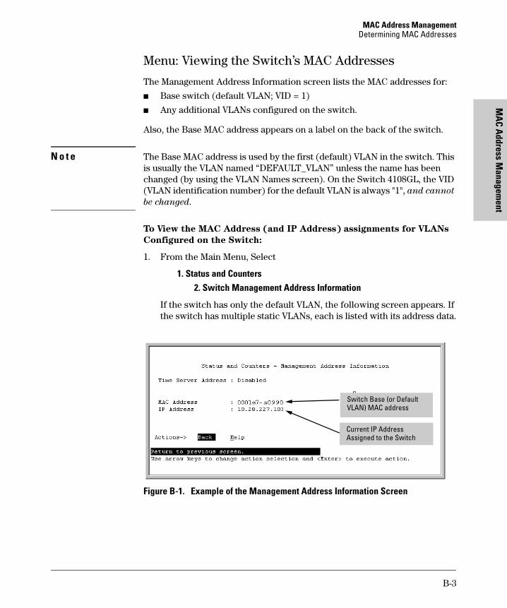
MAC Address ManagementDetermining MAC Addresses
MA
C Address M
anagement
Menu: Viewing the Switch’s MAC Addresses
The Management Address Information screen lists the MAC addresses for:
� Base switch (default VLAN; VID = 1)
� Any additional VLANs configured on the switch.
Also, the Base MAC address appears on a label on the back of the switch.
N o t e The Base MAC address is used by the first (default) VLAN in the switch. This is usually the VLAN named “DEFAULT_VLAN” unless the name has been changed (by using the VLAN Names screen). On the Switch 4108GL, the VID (VLAN identification number) for the default VLAN is always "1", and cannot
be changed.
To View the MAC Address (and IP Address) assignments for VLANs
Configured on the Switch:
1. From the Main Menu, Select
1. Status and Counters2. Switch Management Address Information
If the switch has only the default VLAN, the following screen appears. If the switch has multiple static VLANs, each is listed with its address data.
Figure B-1. Example of the Management Address Information Screen
Switch Base (or Default VLAN) MAC address
Current IP Address Assigned to the Switch
B-3
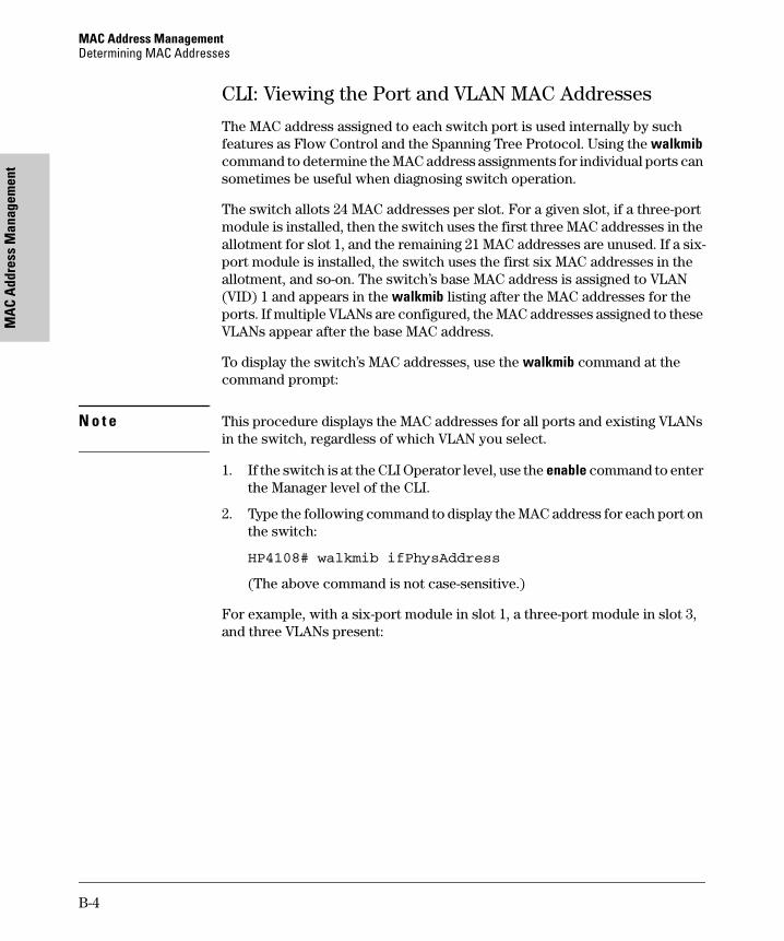
MAC Address ManagementDetermining MAC Addresses
MA
C A
ddre
ss M
anag
emen
t
CLI: Viewing the Port and VLAN MAC Addresses
The MAC address assigned to each switch port is used internally by such features as Flow Control and the Spanning Tree Protocol. Using the walkmib command to determine the MAC address assignments for individual ports can sometimes be useful when diagnosing switch operation.
The switch allots 24 MAC addresses per slot. For a given slot, if a three-port module is installed, then the switch uses the first three MAC addresses in the allotment for slot 1, and the remaining 21 MAC addresses are unused. If a six-port module is installed, the switch uses the first six MAC addresses in the allotment, and so-on. The switch’s base MAC address is assigned to VLAN (VID) 1 and appears in the walkmib listing after the MAC addresses for the ports. If multiple VLANs are configured, the MAC addresses assigned to these VLANs appear after the base MAC address.
To display the switch’s MAC addresses, use the walkmib command at the command prompt:
N o t e This procedure displays the MAC addresses for all ports and existing VLANs in the switch, regardless of which VLAN you select.
1. If the switch is at the CLI Operator level, use the enable command to enter the Manager level of the CLI.
2. Type the following command to display the MAC address for each port on the switch:
HP4108# walkmib ifPhysAddress
(The above command is not case-sensitive.)
For example, with a six-port module in slot 1, a three-port module in slot 3, and three VLANs present:
B-4
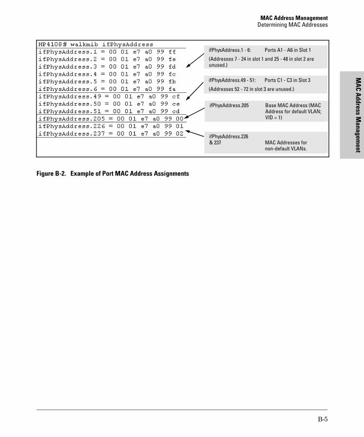
MAC Address ManagementDetermining MAC Addresses
MA
C Address M
anagement
Figure B-2. Example of Port MAC Address Assignments
ifPhysAddress.226 & 237 MAC Addresses for
non-default VLANs.
ifPhysAddress.1 - 6: Ports A1 - A6 in Slot 1
(Addresses 7 - 24 in slot 1 and 25 - 48 in slot 2 are unused.)
ifPhysAddress.49 - 51: Ports C1 - C3 in Slot 3
(Addresses 52 - 72 in slot 3 are unused.)
ifPhysAddress.205 Base MAC Address (MACAddress for default VLAN; VID = 1)
B-5

MAC Address ManagementDetermining MAC Addresses
MA
C A
ddre
ss M
anag
emen
t
B-6
Daylight Savings Tim
e on HP
Procurve Switches
C
Daylight Savings Time on HP Procurve Switches
This information applies to the following HP Procurve switches:
HP Procurve switches provide a way to automatically adjust the system clock for Daylight Savings Time (DST) changes. To use this feature you define the month and date to begin and to end the change from standard time. In addition to the value "none" (no time changes), there are five pre-defined settings, named:
� Alaska
� Canada and Continental US
� Middle Europe and Portugal
� Southern Hemisphere
� Western Europe
The pre-defined settings follow these rules:
Alaska:
• Begin DST at 2am the first Sunday on or after April 24th.
• End DST at 2am the first Sunday on or after October 25th.
Canada and Continental US:
• Begin DST at 2am the first Sunday on or after April 1st.
• End DST at 2am the first Sunday on or after October 25th.
• 2512• 2524• 4108GL
• 1600M• 2400M• 2424M• 4000M• 8000M
• 212M• 224M
• HP AdvanceStack Switches
• HP AdvanceStack Routers
C-1
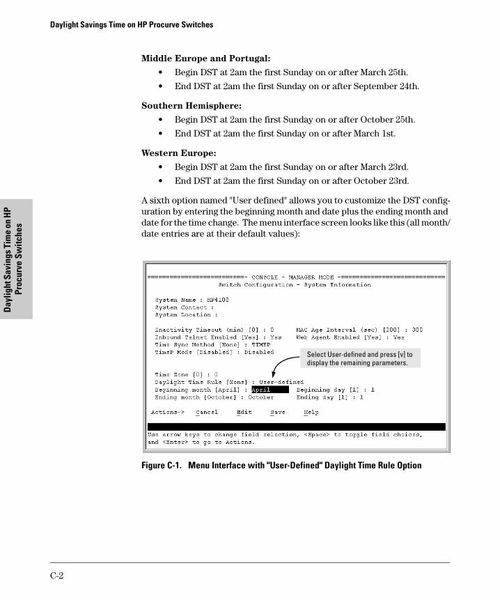
Daylight Savings Time on HP Procurve Switches
Day
light
Sav
ings
Tim
e on
HP
Proc
urve
Sw
itche
s
Middle Europe and Portugal:
• Begin DST at 2am the first Sunday on or after March 25th.
• End DST at 2am the first Sunday on or after September 24th.
Southern Hemisphere:
• Begin DST at 2am the first Sunday on or after October 25th.
• End DST at 2am the first Sunday on or after March 1st.
Western Europe:
• Begin DST at 2am the first Sunday on or after March 23rd.
• End DST at 2am the first Sunday on or after October 23rd.
A sixth option named "User defined" allows you to customize the DST config-uration by entering the beginning month and date plus the ending month and date for the time change. The menu interface screen looks like this (all month/date entries are at their default values):
Figure C-1. Menu Interface with "User-Defined" Daylight Time Rule Option
Select User-defined and press [v] to display the remaining parameters.
C-2

Daylight Savings Time on HP Procurve Switches
Daylight Savings Tim
e on HP
Procurve Switches
Before configuring a "User defined" Daylight Time Rule, it is important to understand how the switch treats the entries. The switch knows which dates are Sundays, and uses an algorithm to determine on which date to change the system clock, given the configured "Beginning day" and "Ending day":
� If the configured day is a Sunday, the time changes at 2am on that day.
� If the configured day is not a Sunday, the time changes at 2am on the first Sunday after the configured day.
This is true for both the "Beginning day" and the "Ending day".
With that algorithm, one should use the value "1" to represent "first Sunday of the month", and a value equal to "number of days in the month minus 6" to represent "last Sunday of the month". This allows a single configuration for every year, no matter what date is the appropriate Sunday to change the clock.
C-3

Index
Index
Symbols
=> prompt … 18-27
Numerics
802.1Q VLAN standard … 16-3802.3u auto negotiation standard … 11-3
A
A.09.70 router release … 14-29aaa authentication … 9-14access
manager … 12-5operator … 12-5
access levels, authorized IP managers … 10-5Actions line … 2-9–2-11
location on screen … 2-9active path … 16-2address table, port … 17-13address, network manager … 12-4advertisement … 14-30alert log … 4-20
alert types … 4-21disabling … 4-25setting the sensitivity level … 4-24sorting the entries … 4-20
analysis, traffic … 12-2APNIC … 7-14Asia-Pacific NIC … 7-14asterisk … 2-10, 2-13authentication trap … 12-8, 12-11authentication trap, configuring … 12-11authorized addresses
for IP management security … 10-5authorized IP managers
access levels … 10-5building IP masks … 10-10configuring in browser interface … 10-9–10-10configuring in console … 10-7definitions of single and multiple … 10-5effect of duplicate IP addresses … 10-13IP mask for multiple stations … 10-11IP mask for single station … 10-10
IP mask operation … 10-5operating notes … 10-13overview … 10-4troubleshooting … 10-13
autoSee GVRP
auto negotiation … 11-4auto port setting … 15-5Auto-10 … 11-11, 11-14auto-discovery … 12-4auto-negotiation … 11-3
B
bandwidthdisplaying utilization … 4-17
blocked link from STP operation … 16-12blocked port
from IGMP operation … 15-5from STP operation … 16-9
boot ROM console … A-3boot ROM mode … 18-27Bootp … 7-3, 7-10, 12-2
Bootp table file … 7-12Bootptab file … 7-12effect of no reply … 18-6gateway ignored … 14-8operation … 7-12using with Unix systems … 7-12
Bootp/DHCP differences … 7-11BPDU … 14-30, 16-3, 16-12bridge protocol data unit … 14-30broadcast domain … 14-4broadcast limit … 11-4, 11-9broadcast storm … 11-11, 16-2, 18-9browser interface
See web browser interfacebrowsers … 4-4
C
CDPCDP on hubs … 12-28configuration … 12-18, 12-21
Index – 1

Inde
x
configuration, viewing … 12-19effect of spanning tree … 12-23general operation … 12-13hold time … 12-23IP address in outbound packet … 12-24mib objects … 12-25neighbor … 12-13neighbor data … 12-25neighbor maximum … 12-27neighbor table … 12-17neighbors table … 12-19neighbors table, resetting … 12-20on individual ports … 12-22overview of operation … 12-12port trunking … 12-27requirements … 12-12terminology … 12-13transmission interval … 12-22transparent devices … 12-18troubleshooting … 18-7version data … 12-27
Clear button … 4-12restoring factory default configuration … 18-26to delete password protection … 9-6
CLIcontext level … 11-8
command line interfaceSee CLI
communities, SNMP … 12-6configuration … 2-7, 16-9
Bootp … 7-12console … 6-3copying … A-13download … A-3factory default … 5-7, 7-2, 14-11, 14-16, 16-3IP … 7-3network monitoring … 17-23permanent … 5-5permanent change defined … 5-4port … 11-1port trunk groups … 11-1quick … 2-8reboot to activate … 2-13restoring factory defaults … 18-26saving from menu interface … 2-10serial link … 6-3SNMP … 12-4–12-5spanning tree protocol … 16-9
startup … 2-10system … 6-8Telnet access configuration … 6-3transferring … A-13trap receivers … 12-8viewing … 5-4VLAN … 14-4web browser access … 6-3
configuration filebrowsing for troubleshooting … 18-24
connection inactivity time … 9-4console … 18-6
configuring … 6-3ending a session … 2-5features … 1-3Main menu … 2-7navigation … 2-9–2-10operation … 2-10starting a session … 2-4status and counters access … 2-7troubleshooting access problems … 18-4
console, for configuringauthorized IP managers … 10-7
context levelglobal config … 7-8
CPU utilization … 17-5
D
date format … 18-16date,configure … 6-12dedicated management VLAN … 14-7default gateway … 7-3default trunk type … 11-17Device Passwords Window … 4-9DHCP … 7-10
address problems … 18-6effect of no reply … 18-6gateway ignored … 14-8
DHCP/Bootp differences … 7-11DHCP/Bootp process … 7-11diagnostics tools … 18-19
browsing the configuration file … 18-24ping and link tests … 18-19
DNS name … 4-6domain … 14-11, 14-16Domain Name Server … 4-6download
2 – Index
Index
SNMP-based … A-11switch-to-switch … A-9troubleshooting … A-12Xmodem … A-6
download OS … A-9download, TFTP … A-3–A-4duplicate IP address
effect on authorized IP managers … 10-13duplicate MAC address
See MAC addressDyn1
See LACP
E
ending a console session … 2-5event log … 2-7, 18-16
navigation … 18-17severity level … 18-16use during troubleshooting … 18-16
F
factory default configurationrestoring … 5-7, 18-26
failure, OS download … A-12Fast EtherChannel
See FECfast mode
spanning tree … 16-4, 16-10fault detection … 4-9fault detection policy … 4-9, 4-24fault detection policy, setting … 4-24fault detection window … 4-24fault-tolerance … 11-11FEC
benefits … 11-29filters
effect of IGMP … 15-20maximum allowed … 15-20
firmware version … 17-5flash memory … 2-10flow control … 11-4flow control, status … 17-9flow control, terminal … 6-3forbid
See GVRPformat, date … 18-16
format, time … 18-16forwarding port, IGMP … 15-5
G
GARPSee GVRP
gateway … 7-3, 7-5gateway (IP) address … 7-4, 7-6gateway, manual config … 14-8global config level … 7-8GVRP
advertisement … 14-43advertisement, defined … 14-30advertisement, responses to … 14-32advertisements, generating … 14-36auto … 14-35benefit … 14-30block … 14-34CLI, configuring … 14-39configurable port options … 14-33configuring learn, block, disable … 14-34convert dynamic to static … 14-33converting to static VLAN … 14-30disable … 14-34dynamic VLAN and reboots … 14-43dynamic VLANs always tagged … 14-31forbid … 14-35GARP … 14-30general operation … 14-31IP addressing … 14-33learn … 14-34learn, block, disable … 14-35menu, configuring … 14-37non-GVRP aware … 14-43non-GVRP device … 14-43operating notes … 14-42port control options … 14-36port-leave from dynamic … 14-36reboot, switch … 14-36recommended tagging … 14-36standard … 14-30tagged, dynamic VLAN … 14-31unknown VLAN … 14-36unknown VLAN, options … 14-33VLAN behavior … 14-8VLAN, dynamic adds … 14-14VLAN, maximun … 14-42
Index – 3
Inde
x
H
Help … 2-11, 4-14Help line, about … 2-9Help line, location on screens … 2-9help, online inoperable … 4-14HP ProCurve
support URL … 4-14HP proprietary MIB … 12-3HP Router 440 … 14-29HP Router 470 … 14-29HP Router 480 … 14-29HP Router 650 … 14-29HP TopTools
See TopToolsHP web browser interface … 1-5
I
ICANN … 7-14IEEE 802.1d … 16-2, 18-9IEEE 802.3ab … 11-4IGMP
benefits … 15-3configuration … 15-10configure per VLAN … 15-5effect on filters … 15-20high-priority forwarding … 15-5host not receiving … 18-8IP multicast address range … 15-20leave group … 15-11maximum address count … 15-20multicast group … 15-11multimedia … 15-3not working … 18-8operation … 15-11–15-12port states … 15-5query … 15-11report … 15-11statistics … 17-19status … 15-12traffic … 15-5
inactivity timeout … 6-4Inbound Telnet Enabled parameter … 18-5interfaces listed … 1-2invalid input … 3-13IP
authorized IP managers … 10-4CLI access … 7-7
configuration … 7-3DHCP/Bootp … 7-3duplicate address … 18-6duplicate address, DHCP network … 18-6effect when address not used … 7-9gateway … 7-3, 14-8gateway (IP) address … 7-4global assignment … 7-14globally assigned addressing … 7-14menu access … 7-5stacking … 7-5subnet mask … 7-3, 7-6using for web browser interface … 4-6web access … 7-9
IP masksbuilding … 10-10for multiple authorized manager
stations … 10-11for single authorized manager station … 10-10operation … 10-5
IP, for SNMP … 12-2IPX
network number … 17-6
J
Java … 4-5–4-6
L
LACPactive … 11-23, 11-26CLI access … 11-18default port operation … 11-27described … 11-13, 11-25Dyn1 … 11-14dynamic … 11-26enabling dynamic trunk … 11-23full-duplex required … 11-4, 11-11, 11-25IGMP … 11-28no half-duplex … 11-28outbound traffic distribution … 11-30overview … 11-12passive … 11-23, 11-26removing port from dynamic trunk … 11-24restrictions … 11-28standby link … 11-26status, terms … 11-27
4 – Index

Index
STP … 11-28VLANs … 11-28
LACP, with CDP … 12-27learning bridge … 7-2leave group
See IGMPlegacy VLAN … 14-6limit, broadcast … 11-9link speed, port trunk … 11-11link test … 18-20
for troubleshooting … 18-19link, serial … 6-3load balancing
See port trunkloop, network … 11-11, 16-2, 16-9lost password … 4-12
M
MAC address … 7-12, 17-5, B-1duplicate … 18-9, 18-12learned … 17-12–17-13port … B-1, B-3switch … B-1VLAN … 14-28, B-1
managementinterfaces described … 1-2server URL … 4-13–4-14server URL default … 4-15
manager access … 12-5manager password … 4-9, 4-11, 9-4–9-6manager password recommended … 9-13Manual, IP address … 7-6maximum VLANs, GVRP … 14-42media type, port trunk … 11-11memory
flash … 2-10startup configuration … 2-10
menu interfaceconfiguration changes, saving … 2-10
messageVLAN already exists … 14-22
MIB … 12-3MIB listing … 12-3MIB, HP proprietary … 12-3MIB, standard … 12-3Microsoft Internet Explorer … 4-5mirroring
See port monitoring.monitoring traffic … 17-23monitoring, traffic … 12-2multicast group
See IGMPmultimedia
See IGMPmultiple VLAN … 12-2multi-port bridge … 7-2
N
navigation, console interface … 2-9–2-10navigation, event log … 18-18Netscape … 4-5network management functions … 12-4network manager address … 12-4network monitoring
traffic overload … 17-23Network Monitoring Port screen … 17-23network slow … 18-6notes on using VLANs … 14-10
O
online help … 4-14online help location … 4-14operating notes
authorized IP managers … 10-13operator access … 12-5operator password … 4-9, 4-11, 9-4–9-6OS
version … A-5, A-7, A-10OS download
failure indication … A-12switch-to-switch download … A-9troubleshooting … A-12using TFTP … A-3
out-of-band … 1-3
P
password … 4-9, 4-11browser/console access … 9-4case-sensitive … 9-5creating … 4-9delete … 2-7, 4-12, 9-6deleting with the Clear button … 9-6
Index – 5

Inde
x
if you lose the password … 4-12, 9-6incorrect … 9-5length … 9-5lost … 4-12manager … 4-9operator … 4-9set … 2-7setting … 4-10, 9-5using to access browser and console … 4-11
path cost … 16-10ping test … 18-20
for troubleshooting … 18-19port
address table … 17-13auto negotiation … 11-4auto, IGMP … 15-5auto-negotiation … 11-3blocked by STP operation … 16-9blocked, IGMP … 15-5broadcast limit … 11-9CLI access … 11-6context level … 11-8cost
See spanning tree protocol.counters … 17-9counters, reset … 17-9fiber-optic … 11-4forwarding, IGMP … 15-5full-duplex, LACP … 11-4MAC address … B-3–B-4menu access … 11-5monitoring … 14-28numbering … 11-2See port trunkspeed change, transceiver … 11-4state, IGMP control … 15-5traffic patterns … 17-9utilization … 4-17
web browser interface … 4-17web browser access … 11-9
Port Configuration … 11-1port security
port trunk restriction … 11-11trunk restriction … 11-15
port trunk … 11-10bandwidth capacity … 11-10caution … 11-11, 11-16, 11-24CLI access … 11-18
default trunk type … 11-17enabling dynamic LACP … 11-23FEC … 11-13, 11-29IGMP … 11-15LACP … 11-4LACP, full duplex required … 11-11limit … 11-10link requirements … 11-11media requirements … 11-14media type … 11-11menu access to static trunk … 11-16monitor port restrictions … 11-15nonconsecutive ports … 11-10port security restriction … 11-15removing port from static trunk … 11-21requirements … 11-14SA/DA … 11-30See also LACPSee LACPspanning tree protocol … 11-15static trunk … 11-14static trunk, overview … 11-12STP … 11-15STP operation … 11-14traffic distribution … 11-14Trk1 … 11-14trunk (non-protocol) option … 11-13trunk option described … 11-28types … 11-13VLAN … 11-15, 14-28VLAN operation … 11-14web browser access … 11-24
port trunk groupinterface access … 11-1
power interruption, effect on event log … 18-16primary VLAN
See VLANpriority … 15-5
See spanning treeprompt, => … 18-27proprietary MIB … 12-3public SNMP community … 12-4
Q
querySee IGMP
quick configuration … 2-8
6 – Index
Index
quick start … iii, 7-4
R
reboot … 2-8, 2-10, 2-12, 14-36reboot, actions causing … 5-3reconfigure … 2-10redundant path … 16-2, 16-9
spanning tree … 16-3report
See IGMPreset … 2-12, 5-9Reset button
restoring factory default configuration … 18-26reset port counters … 17-9resetting the switch
factory default reset … 18-26restricted access … 12-5restricted write access … 12-5RFC
See MIBRFC 1213 … 12-3RFC 1493 … 12-3RFC 1515 … 12-3RFC 1573 … 12-3RFC 1757 … 12-3RIPE NCC … 7-14RMON … 12-2RMON groups supported … 12-11router … 14-29, 15-11
gateway … 7-6router release A.09.70 … 14-29RS-232 … 1-3
S
security … 4-12, 6-3authorized IP managers … 10-4
Self Test LEDbehavior during factory default reset … 18-26
serial number … 17-5server
access failure … 16-3setting a password … 9-5setting fault detection policy … 4-24setup screen … iii, 7-4severity code, event log … 18-16slow network … 18-6
SNMP … 12-2CLI commands … 12-5communities … 12-4–12-6Communities screen … 12-5communityconfigure … 12-4IP … 12-2public community … 12-4–12-5restricted access … 12-5traps … 12-2
SNMP-based download … A-11SNTP
broadcast mode … 8-2, 8-9broadcast mode, requirement … 8-3configuration … 8-4disabling … 8-10enabling and disabling … 8-9event log messages … 8-23menu interface operation … 8-23operating modes … 8-2poll interval … 8-12See also TimeP and SNTP. … 8-3selecting … 8-3unicast mode … 8-3, 8-10unicast time polling … 8-20unicast, address priority … 8-21unicast, deleting addresses … 8-22unicast, replacing servers … 8-22viewing … 8-4, 8-8
software version … 17-5sorting alert log entries … 4-20spanning tree … 16-2
blocked link … 16-12blocked port … 16-9description of operation … 16-9enabling from the browser interface … 16-9enabling in the CLI … 16-6fast mode … 16-4, 16-10global information … 17-17information screen … 17-17link priority … 16-3port cost … 16-9port priority automatic setting … 16-9problems related to … 18-9statistics … 17-17using with port trunking … 11-15VLAN effect on … 14-27
spanning tree and CDP … 12-23
Index – 7

Inde
x
stackingbenefits … 13-4–13-5minimum software version, other HP
switches … 13-10primary … 13-47
standard MIB … 12-3starting a console session … 2-4static VLAN, convert to … 14-30statistical sampling … 12-2statistics … 2-7, 17-3statistics, clear counters … 2-12, 5-9status and counters
access from console … 2-7status and counters menu … 17-4status overview screen … 4-7STP
See spanning tree.spanning treeserver access failure … 16-3
subnet … 15-12subnet address … 14-4subnet mask … 7-4, 7-6
See also IPsupport
changing default URL … 4-14URL … 4-13URL Window … 4-13
switch consoleSee console
switch setup menu … 2-8switch-to-switch download … A-9system configuration screen … 6-8System Name parameter … 6-9
T
TACACSaaa parameters … 9-16authentication … 9-10authentication process … 9-24authentication, local … 9-25authorized IP managers, effect … 9-29configuration, authentication … 9-16configuration, encryption key … 9-23configuration, server access … 9-19configuration, timeout … 9-24configuration, viewing … 9-15encryption key … 9-12, 9-19–9-20, 9-23encryption key, general operation … 9-26
encryption key, global … 9-23general operation … 9-8IP address, server … 9-19local manager password requirement … 9-29messages … 9-28NAS … 9-9overview … 9-2precautions … 9-11preparing to configure … 9-14preventing switch lockout … 9-19privilege level code … 9-12server access … 9-19server priority … 9-22setup, general … 9-11show authentication … 9-14supported features … 9-9system requirements … 9-10TACACS+ server … 9-9testing … 9-11timeout … 9-19troubleshooting … 9-11, 9-29unauthorized access, preventing … 9-13web access, controlling … 9-28web access, no effect on … 9-11
tacacs-server … 9-14tagged VLAN
See VLANTCP/IP reference book … 7-14Telnet … 2-4, 9-19Telnet, enable/disable … 6-4Telnet, problem … 18-5terminal access, lose connectivity … 6-6terminal type … 6-3test … 9-19TFTP
download … A-4OS download … A-3
threshold setting … 12-4time format … 18-16time protocol
selecting … 8-3time server … 7-3time, configure … 6-12TimeP … 7-3, 7-5
assignment methods … 8-2disabling … 8-19enabling and disabling … 8-17poll interval … 8-19
8 – Index

Index
selecting … 8-3viewing and configuring, menu … 8-14viewing, CLI … 8-16
timesync, disabling … 8-19Time-To-Live … 7-3, 7-5top talker … 11-30TopTools … 1-6TopTools system requirements … 4-5TopTools, main screen … 1-6traffic analysis … 12-2traffic monitoring … 12-2, 12-4traffic, monitoring … 17-23traffic, port … 17-9transceiver, fiber-optic … 11-4transceiver, speed change … 11-4trap … 4-25
authentication … 12-8authentication trap … 12-11CLI access … 12-9event levels … 12-9limit … 12-9receiver … 12-8SNMP … 12-9Trap Receivers Configuration screen … 12-8
trap receiver … 12-4, 12-8configuring … 12-10
troubleshoot … 9-19troubleshooting
approaches … 18-3authorized IP managers … 10-13browsing the configuration file … 18-24console access problems … 18-4diagnosing unusual network activity … 18-6diagnostics tools … 18-19OS download … A-12ping and link tests … 18-19restoring factory default configuration … 18-26switch won’t reboot, shows => prompt … 18-27unusual network activity … 18-6using the event log … 18-16web browser access problems … 18-4
trunkSee port trunk
trunk groupFEC … 11-26
TTL … 7-3, 7-5types of alert log entries … 4-21
U
unauthorized access … 12-11Universal Resource Locator
See URLUnix, Bootp … 7-12unrestricted write access … 12-5unusual network activity … 18-6up time … 17-5URL … 4-14
browser interface online help location … 4-14HP ProCurve … 4-14management … 4-14management server … 4-13–4-14support … 4-13–4-14
user namecleared … 9-6
user name, using for browser or console access … 4-9, 4-11
using the passwords … 4-11utilization, port … 4-17
V
version, OS … A-5, A-7, A-10VID
See <default para text>VLANvirtual stacking
transmission interval range … 13-17–13-18VLAN … 7-4, 14-4, 14-27, 18-13, B-1
802.1Q … 16-12address … 12-2Bootp … 7-12configuring Bootp … 7-12convert dynamic to static … 14-30dedicated management … 14-7DEFAULT_ VLAN … 14-7deleting … 14-29device not seen … 18-12DHCP, primary VLAN … 14-8dynamic … 14-4, 14-10–14-11, 14-16effect on spanning tree … 14-27event log entries … 18-16gateway, IP … 14-8ID … 3-15IGMP configuration … 15-5limit … 14-11, 14-16link blocked … 18-9MAC address … 14-28
Index – 9

Inde
x
maximum, GVRP … 14-42monitoring … 17-2multiple … 12-2multiple VLANs on port … 14-25notes on using … 14-10number allowed, including dynamic … 14-14OS download … A-3port assignment … 14-14port configuration … 14-26, 18-12port monitoring … 14-28port restriction … 14-29port trunk … 14-28primary … 7-3, 13-10, 13-35, 13-47, 14-8primary VLAN … 14-7primary, CLI command … 14-17, 14-19primary, select in menu … 14-12primary, web configure … 14-22primary, with DHCP … 14-10reboot required … 2-8restrictions … 14-29See GVRPspanning tree operation … 16-12stacking, primary VLAN … 14-8static … 14-4, 14-8, 14-11, 14-16support enable/disable … 2-8switch capacity … 14-4tagged … 14-5tagging … 14-23, 14-25tagging broadcast, multicast, and unicast
traffic … 18-11unknown VLAN … 14-36untagged … 14-6, 14-15VID … 14-4, 14-25VID, default VLAN … 14-8
VLAN already exists, message … 14-22VLAN ID
See VLAN … 3-15VT-100 terminal … 6-3
W
warranty … iiweb agent enabled … 4-2web agent,
advantages … 1-5web browser access configuration … 6-3web browser enable/disable … 6-4web browser interface
access parameters … 4-9alert log … 4-7, 4-20alert log details … 4-22alert types … 4-21bandwidth adjustment … 4-18bar graph adjustment … 4-18configuration, support URL … 4-14disable access … 4-2enabling … 4-5error packets … 4-17fault detection policy … 4-9, 4-24fault detection window … 4-24features … 1-5first-time install … 4-8first-time tasks … 4-8help via TopTools … 4-14main screen … 4-16management server URL … 4-14online help … 4-14online help location specifying … 4-14online help, inoperable … 4-14overview … 4-16Overview window … 4-16password lost … 4-12password, setting … 4-10port status … 4-19port utilization … 4-17port utilization and status displays … 4-17screen elements … 4-16security … 4-2, 4-9standalone … 4-5status bar … 4-23status indicators … 4-23status overview screen … 4-7system requirements … 4-4–4-5troubleshooting access problems … 18-4URL default … 4-15URL, management server … 4-15URL, support … 4-15
web browser interface, for configuringauthorized IP managers … 10-9–10-10IGMP … 15-10STP … 16-9
web site, HP … 12-3world wide web site, HP
See HP ProCurvewrite access … 12-5write memory … 14-43
10 – Index

Index
write memory, effect on menu interface … 2-13
X
Xmodem OS download … A-6
Index – 11


Technical information in this documentis subject to change without notice.
©Copyright Hewlett-Packard Company 2001.All right reserved.Reproduction, adaptation, or translationwithout prior written permission is prohibitedexcept as allowed under the copyright laws.
Product of U.S.A.April 2001
Manual Part Number
*5969-2378*
5969-2378