Embed Size (px)
Citation preview

MANAGED PRESSURE DRILLING TECHNIQUES AND TOOLS
A Thesis
by
MATTHEW DANIEL MARTIN
Submitted to the Office of Graduate Studies of Texas A&M University
in partial fulfillment of the requirements for the degree of
MASTER OF SCIENCE
May 2006
Major Subject: Petroleum Engineering

MANAGED PRESSURE DRILLING TECHNIQUES AND TOOLS
A Thesis
by
MATTHEW DANIEL MARTIN
Submitted to the Office of Graduate Studies of Texas A&M University
in partial fulfillment of the requirements for the degree of
MASTER OF SCIENCE
Approved by: Chair of Committee, Hans C. Juvkam-Wold Committee Members, Jerome J. Schubert Ann E. Jochens Head of Department, Stephen A. Holditch
May 2006
Major Subject: Petroleum Engineering

iii
ABSTRACT
Managed Pressure Drilling Techniques and Tools.
(May 2006)
Matthew Daniel Martin, B.S., Texas A&M University
Chair of Advisory Committee: Dr. Hans C. Juvkam-Wold
The economics of drilling offshore wells is important as we drill more wells
in deeper water. Drilling-related problems, including stuck pipe, lost circulation,
and excessive mud cost, show the need for better drilling technology. If we can
solve these problems, the economics of drilling the wells will improve, thus
enabling the industry to drill wells that were previously uneconomical. Managed
pressure drilling (MPD) is a new technology that enables a driller to more
precisely control annular pressures in the wellbore to prevent these drilling-
related problems. This paper traces the history of MPD, showing how different
techniques can reduce drilling problems.
MPD improves the economics of drilling wells by reducing drilling
problems. Further economic studies are necessary to determine exactly how
much cost savings MPD can provide in certain situation. Furter research is also
necessary on the various MPD techniques to increase their effectiveness.

iv
DEDICATION This thesis is dedicated to my parents for all their support and encouragement
throughout the years.

v
ACKNOWLEDGMENTS
I would like to first thank Dr. Hans C. Juvkam-Wold for the chance to do this research and for all of the advice throughout the years.
I would also like to thank Dr. Jerome Schubert and Dr. Ann Jochens for helping me in completing this thesis and for being on my committee.
Thanks also to ConocoPhillips and the Crisman Institute for providing funding for this project.
And last but not least, I would like to thank all my friends at Texas A&M
University for their support and encouragement.

vi
TABLE OF CONTENTS Page ABSTRACT.......................................................................................................... iii
DEDICATION....................................................................................................... iii
ACKNOWLEDGMENTS ....................................................................................... v
TABLE OF CONTENTS....................................................................................... vi
LIST OF TABLES................................................................................................ vii
LIST OF FIGURES .............................................................................................viii
INTRODUCTION ..................................................................................................1
BASICS OF MANAGED PRESSURE DRILLING..................................................2
UBD vs. MPD ....................................................................................................3 Pressure-Gradient Windows..............................................................................3 How Managed Pressure Drilling Works.............................................................6 The Need for Managed Pressure Drilling ..........................................................7
MANAGED PRESSURE DRILLING TECHNIQUES ...........................................13
Continuous Circulation System .......................................................................13 ECD Reduction Tool........................................................................................17 Pressurized Mud Cap Drilling..........................................................................30 Controlled Mud Cap System............................................................................33 Dual-Gradient Drilling Method .........................................................................41
FUTURE OF MANAGED PRESSURE DRILLING ..............................................46
CONCLUSIONS..................................................................................................48
RECOMMENDATIONS.......................................................................................51
NOMENCLATURE..............................................................................................52
REFERENCES ...................................................................................................53
VITA....................................................................................................................56

vii
LIST OF TABLES
Page
Table 1 NPT downtime�TVD> 15,000 ft. (From Dodson7). .............................9 Table 2 NPT cost of 102 wells drilled with TVD > 15,000 ft (From Dodson7). 10 Table 3 NPT downtime�TVD< 15,000 ft. (From Dodson7). ...........................11 Table 4 NPT cost of 549 wells drilled�TVD < 15,000 ft (From Dodson7).......12 Table 5 Results of Case 1� Drilling 8-1/2-in. hole to 3800 m (From Jenner3)39 Table 6 Results of Case 2� Drilling 12-1/4" hole to 3800 m (From Jenner3) .40

viii
LIST OF FIGURES
Page
Fig. 1 Pressure-gradient profile (From Juvkam-Wold5). ..................................4 Fig. 2 Pressure gradient window for tight margins (From Hannegan6)............5 Fig. 3 Report of drilling downtime�TVD> 15,000 ft. (From Dodson7).............8 Fig. 4 Report of drilling downtime �TVD < 15,000 ft (From Dodson7)..........11 Fig. 5 Change in equivalent mud weight during connections
(From Jenner6)....................................................................................14 Fig. 6 Coupler device used in the continuous circulation system
(From Jenner8)....................................................................................15 Fig. 7 Pressure-gradient profile showing effect of ECD reduction tool
(From Hannegan6). .............................................................................20 Fig. 8 Pressure boost provided by ECD reduction tool vs. flow rate
(From Bern10)......................................................................................22 Fig. 9 Flow rate in well vs pressure boost caused by ECD reduction tool
(From Bern10)......................................................................................23 Fig. 10 Downhole pressure reduction seen as a result of ECD reduction tool
(From Bern10)......................................................................................24 Fig. 11 Additional standpipe pressure needed for pressure boost with ECD
reduction tool (From Bern10). ..............................................................25 Fig. 12 Surge effect when tripping drillstring with ECD reduction
(From Bern10)......................................................................................27 Fig. 13 Swab effect when tripping drillstring with ECD reduction
(From Bern10)......................................................................................28 Fig. 14 Surge effects as a function of trip time per stand (From Bern10). ........29 Fig. 15 Pressure-gradient profile for pressurized mud cap drilling method
(From Hannegan6). .............................................................................31 Fig. 16 Controlled mud cap setup (From Juvkam-Wold5)................................35

ix
Fig. 17 Dual-gradient drilling pressure gradient profile (From Hannegan6) .....41 Fig. 18 Pressure profile for drilling dual gradient without a riser
(From Hannegan6). .............................................................................43 Fig. 19 Pressure profile for riserless dual gradient drilling with zero
discharge (From Hannegan6)..............................................................44

1
INTRODUCTION
As current reserves deplete, it is necessary to drill to reservoirs that are
deeper and more complex. Some industry professionals would say that 70% of
the current hydrocarbon offshore resources are economically undrillable using
conventional drilling methods.1 Managed Pressure Drilling (MPD) is a new
technology that uses tools similar to those of underbalanced drilling to better
control pressure variations while drilling a well. The aim of MPD is to improve the
drillability of a well by alleviating drilling issues that can arise.
MPD can improve economics for any well being drilled by reducing a rig�s
nonproductive time (NPT). NPT is the time that a rig is not drilling. Many of the
drilling problems in any well can be reduced by using MPD. As with any new
technology, MPD introduces new techniques that require understanding;
becoming confident enough in the technology to use it on a regular basis takes
time. With the resources that are currently uneconomical in the offshore markets
and the problems that occur while drilling a well, it is important that industry look
to MPD to improve the drilling ability of the drilling rigs.
This literature review summarizes reported successes of MPD over the
last 10 years and shows that additional work is still necessary for the complete
evaluation of the technique.
This thesis follows the style of SPE Drilling and Completion.

2
BASICS OF MANAGED PRESSURE DRILLING
Managed pressure drilling (MPD) is �an adaptive drilling process to
precisely control the annular pressure profile throughout the well.�2 The main
idea is to create a pressure profile in the well to stay within close tolerances and
close to the boundary of the operation envelope defined by the pore pressure,
hole stability envelope and fracture pressure.3 MPD uses many tools to mitigate
the risks and costs associated with drilling wells by managing the annular
pressure profile. These techniques include controlling backpressure, fluid
density, fluid rheology, annular fluid level, circulating friction, and hole geometry
in any combination.4
The International Association of Drilling Contractors (IADC) has defined
MPD further by creating two categories.4 Reactive MPD includes drilling
programs that are tooled up with at least a rotating control device (RCD), choke,
and perhaps drill string float to safely and efficiently deal with problems that could
occur downhole. Proactive MPD includes designing a casing, fluids and openhole
program that precisely manages the wellbore pressure profile. This category of
MPD can offer the greatest benefit to the offshore drilling industry as it can deal
with unforeseen problems before they occur.
3
UBD vs. MPD MPD is similar to underbalanced drilling (UBD). It uses many of the same
tools that were designed for UBD operations. The difference between the
methods is that UBD is used to prevent damage to the reservoir while the
purpose of MPD is to solve drilling problems.4 UBD allows influx of formation
fluids by drilling with the pressure of the fluid in the wellbore lower than the pore
pressure. MPD manages the pressure to remain between the pore pressure and
the fracture pressure of the reservoir. It is set up to handle the influx of fluids that
may occur while drilling but does not encourage influx. UBD is reservoir-issue
related while MPD is drilling-issue related.
Pressure-Gradient Windows
As a well is drilled, drilling fluid is circulated in the hole to obtain a specific
bottom hole pressure. The density of the fluid is determined by the formation and
pore pressure gradients and the wellbore stability.
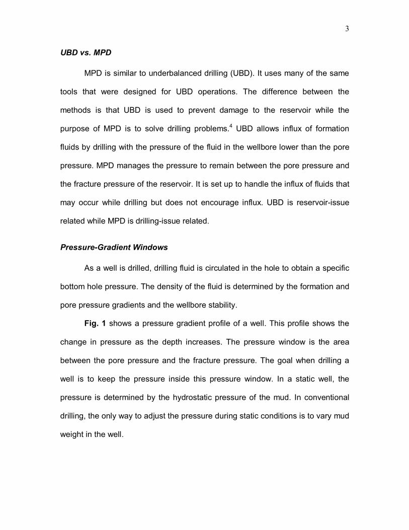
Fig. 1 shows a pressure gradient profile of a well. This profile shows the
change in pressure as the depth increases. The pressure window is the area
between the pore pressure and the fracture pressure. The goal when drilling a
well is to keep the pressure inside this pressure window. In a static well, the
pressure is determined by the hydrostatic pressure of the mud. In conventional
drilling, the only way to adjust the pressure during static conditions is to vary mud
weight in the well.

4
Fig. 1� Pressure-gradient profile (From Juvkam-Wold5).
Fig. 2 shows the problem that can occur when dealing with tight pressure-
gradient windows. When the well is static, the pressure in the well is less than the
pore pressure and the well takes a kick; that is, hydrocarbons flow into the well.6
Before drilling can begin again, the kick has to be circulated out. After a
connection, the pumps restart, the BHP (Bottom Hole Pressure) increases, and
PRESSURE
DEPTH
Mud Hydrostatic
Fracture Pressure
Pore Pressure

5
TVD
psi
STATICBHP = HH(MW)
AFP
CONVENTIONAL CIRCULATION � TIGHT MARGINS
DYNAMICBHP = HH(MW) + AFP
Note: In tight margins, well can flow statically, and lose returns when circulating.
TVD
psipsi
STATICBHP = HH(MW)
AFP
CONVENTIONAL CIRCULATION � TIGHT MARGINS
DYNAMICBHP = HH(MW) + AFP
Note: In tight margins, well can flow statically, and lose returns when circulating.
the pressure goes above the fracture-pressure, resulting in lost circulation, or
fluid flowing into the formation. The goal of managed pressure drilling is to �walk
the line� of the pressure gradients. Managing the pressure and remaining inside
this pressure gradient window can avoid many drilling problems.
Fig. 2� Pressure gradient window for tight margins (From Hannegan6).

6
How Managed Pressure Drilling Works The basic technique in MPD is to be able to manipulate the BHP and the
pressure profile as needed. In conventional drilling, the BHP can be calculated by
summing the mud weight hydrostatic head and the annular friction pressure
(AFP). The AFP is the friction pressure that results from the circulation of the
mud while drilling. ECD is defined as the equivalent circulating density of the
BHP. It is basically the BHP while circulating converted into the units of mud
weight. During a connection, the pumps turn off and the fluid stops circulating,
thus eliminating the annular friction pressure. The starting and stopping of
pumps can greatly affect the pressure profile, causing the pressure to fluctuate
out of the pressure-gradient window and thus leading to drilling problems.
A conventional drilling system is open to the atmosphere so that the
returns gravity flow away from the rig floor.3 The only way to adjust BHP while
drilling is by the pumping rate. MPD uses a closed and pressurizable mud
system. With a closed system the equation for the BHP can be varied to include
backpressure. BHP now can be found by summing the mud hydrostatic and the
AFP with the amount of backpressure being applied. Adjusting backpressure
while drilling can quickly change the BHP.
The basic configuration for MPD is to have a rotating control device (RCD)
and a choke.4 The RCD diverts the pressurized mud returns from the annulus to
the choke manifold. A seal assembly with the RCD enables the mud returns
system to remain closed and pressurized and enables the rig to drill ahead. The
choke with the pressurized mud return system allows the driller to apply

7
backpressure to the wellbore. If the pressure starts to climb above the fracture
pressure of the formation, the driller can open the choke to reduce backpressure
and bring the pressure down. If the driller needs to increase the pressure
throughout the well, closing the choke will increase backpressure. This technique
is mainly used during connections when the pumps are turned off then on. When
the pumps are turned off, the choke is closed to apply backpressure to replace
the lost AFP. As the pumps are turned on and the AFP increases, the choke can
be opened to decrease backpressure. This helps keep pressure profile to remain
inside the pressure window throughout the well.
In Fig. 2, the pressure profile shows that, in static conditions, the pressure
will fall below the pore pressure and that, while circulating, the pressure will
exceed the fracture pressure. By adjusting the mud weight and using
backpressure, a driller would be able to keep the pressure inside the pressure
window. The driller can decrease mud weight so that the pressure stays below
the fracture pressure while circulating. Applying back pressure while not
circulating could keep the pressure above the pore pressure of the formation. By
adjusting the drilling plan, a driller would be able to successfully drill a well that
has tight pressure margins.
The Need for Managed Pressure Drilling
The need for MPD is clearly illustrated by current drilling statistics and
problems that currently exist. Fig. 3 shows the results of a database search of
NPT while drilling offshore gas wells.

8
Fig. 3� Report of drilling downtime�TVD> 15,000 ft. (From Dodson7).
MPD can solve a large percentage of the problems the database lists, especially
those that are caused by wellbore pressure deviating out of the pressure gradient
window during drilling operations.4 Table 1 shows the NPT from Fig. 3 that could
be reduced by using MPD.

9
Table 1� NPT downtime�TVD> 15,000 ft. (From Dodson7).
Numerous problems can occur if the wellbore pressure goes below the pore-
pressure gradient. At shallow depths, water or gas can flow into the wellbore. As
noted above, a kick can occur. With a lower pressure in the wellbore, the hole
can also become unstable and start to fall in on the drillpipe. This can lead to the
pipe becoming stuck and could cause a twist off, which is breaking the pipe. The
main problem when the pressure exceeds the fracture pressure-gradient is lost
circulation, losing mud into the formation. Reservoir damage can also occur and
the wellbore can become unstable. These problems account for more than 40%
of drilling problems in the 10 years this study covers.
Table 27 shows the economic impact that these hole problems have on
drilling cost. These hole problems basically cost a company $98 per foot drilled. If
we can eliminate the problems with MPD, we could reduce hole costs by about
$39 per foot drilled. On wells drilled to 15,000 ft, that can equate to an average
savings of $585,000 per well. These figures assume that MPD will reduce the
downtime by 40%. MPD will reduce these problems, although other events could
still occur to prevent solving some of these problems. Even if we assume MPD
Lost Circulation 12.8% Stuck Pipe 11.1%
Kick 9.7% Twist Off 4.2%
Shallow Water/Gas Flow 2.0%
Wellbore Instability 0.6% Total Downtime 40.4%

10
could reduce that 40% to 20%, it could result in a savings of $19.50 per foot, or
an average savings of $293,000 per well that is drilled to a depth of 15,000 ft.
Table 2� NPT cost of 102 wells drilled with TVD > 15,000 ft (From Dodson7).
Fig. 4 shows similar results for offshore wells that were drilled to less than
15,000 ft. Table 3 shows the NPT for these wells that could be reduced by using
MPD.
Total Drill Days
NPT Time, days NPT %
Dry Hole Cost/Foot Cost/ft Due to NPT
7680 1703 22 $444 $98

11
Fig. 4�Report of drilling downtime �TVD < 15,000 ft (From Dodson7).
Table 3� NPT downtime�TVD< 15,000 ft. (From Dodson7).
Lost Circulation 12.7% Stuck Pipe 11.6%
Kick 8.2% Twist Off 1.7%
Shallow Water/Gas Flow 3.7%
Wellbore Instability 0.7% Total Downtime 38.6%

12
Table 4 shows the economic impact of these problems. If MPD eliminated
the 38% of drilling problems, the benefit could be $27 per foot.
Table 4� NPT cost of 549 wells drilled�TVD < 15,000 ft (From Dodson7).
On a 10,000 ft well, a savings of $270,000 can be made. If MPD only
reduces these problems by half, the benefit of $13.50 per foot would yield an
average savings of $135,000 per well that is drilled to a depth of 10,000 ft.
These statistics show that MPD can help reduce NPT for current drilling
operations with associated excellent economic benefits. These economic
benefits illustrate the need for MPD with current operations to help companies
reduce their drilling costs.
Total Drill Days
NPT Time (days) NPT %
Dry Hole Cost/Foot
Cost/ft Due to NPT
17641 4264 24 $291 $71

13
MANAGED PRESSURE DRILLING TECHNIQUES
Projects that have used five of the many different variations of MPD have
demonstrated techniques that are proactive in managing the pressure profile.
Continuous Circulation System
The continuous circulation system8 (CCS) is a new technology that
enables a driller to make connections without stopping fluid circulation. A CCS
enables a driller to maintain a constant ECD when making connections. In
normal drilling operations, a driller must turn the pumps off when making a
connection. Numerous problems can occur as pumps start and stop in a drilling
operation.
In a narrow drilling window, where the pore pressure and fracture pressure
gradients are close, continuous circulation can prevent many problems from
occurring.
Fig. 5 shows the pressure spikes that occur when making a connection.
When the pumps stop, the pressure in the well decreases. This decrease in
pressure can cause a kick, formation fluids enter the wellbore. The formation
could also relax and the formation could collapse on the hole, resulting in stuck
pipe. The differential pressure between the reservoir and the wellbore can also
stick the pipe. The drilling fluid starts to form a gel when the pumps are turned off
as the fluids stop circulating. When the pumps are restarted, pressure increases
to break the gel, causing a pressure spike which could cause lost circulation,
where fluids enter the formation, and ballooning of the wellbore. Before a

14
connection is made, the rig has downtime associated with circulating the cuttings
out of the bottomhole assembly.8 This is required so that the cuttings do not
settle at the bottomhole assembly.
Fig. 5�Change in equivalent mud weight during connections (From Jenner6).
A CCS could solve these problems when drilling.8 It would enable a driller
to have improved control of the ECD and reduce these problems that can result
from shutting down the pumps during a connection.

15
Fig. 6 shows a coupler8, the device that enables the continuous circulation
of the fluid. The drillstring passes through this device, and during the connection
process it provides a seal around the drillstring. The coupler can be divided into
an upper and lower section. A sealing device can separate the two sections.
Fig. 6� Coupler device used in the continuous circulation system (From Jenner8).

16
Fig. 6 also shows the mud flow that occurs during connections.8 When it
is time to make a connection, the fluid flows into the coupler, thus equalizing the
pressure around the drillstring. With the pressure equalized, the connection is
broken and the tool joint pin is backed out and raised out of the lower section.
The sealing device then closes and the pressure in the upper chamber is bled
off, allowing the tool joint pin to be removed. The fluid that is in the upper
chamber drains back into the mud pit. The lower section continues to circulate
fluid down the hole during the entire operation. The new joint of drillpipe is then
lowered into the upper chamber. The chamber is sealed and repressured by fluid
from the circulating system. Once the pressure is equalized between the two
chambers, the dividing seal opens. The drillpipe joint is lowered and a connection
is made. Once the connection is made, the pressure is bled off and the seals are
opened so that normal drilling operations can continue.
In a field trial in 2003,8 the CCS was tested for 14 hours drilling a 12 ¼-in.
hole. The system made 72 connections. The first 6 were done manually to
calibrate the system. The rest of the connections were controlled automatically
by the driller using a touch screen. Circulation rate for the test was 800 gpm and
pressure was kept between 2,800 and 3,000 psi. The test showed that the
continuous circulation system can be used to drill sections of the well without
turning the pumps off during a connection. After the test was run, the drillpipe
used was tested and no damage was found on the drillpipe that was handled by
the coupler. The connection times ranged from 13 to 20 minutes. The actual

17
connection time can be reduced to about 8 minutes with improvement in the
guidance system when performing the connection.8
The continuous circulation system is useful in preventing pressure spikes
when making connections, thus reducing wellbore problems. Benefits of using
the CCS include9
• Reducing nonrotation time by eliminating the need to circulate the
cuttings out of the bottom hole assembly.
• Reducing the possibility of a stuck drillstring by keeping the cuttings
from dropping to the bottom.
• Constant ECD can be maintained.
ECD Reduction Tool
A better understanding of equivalent circulating density (ECD) is
necessary to understand how this tool can help manage the pressure profile
window. A high ECD can cause problems in complex wells, including reducing
the operating margin between the pore pressure and fracture pressure. If a well
has wellbore stability issues then a higher downhole pressure may be required.10
A high ECD in this case could result in exceeding the fracture pressure of a
formation. With a high ECD, a common problem is lost circulation.
ECD is a function of mud density, mud rheology, cuttings loading, annular
geometry and flow rate. 10 Drilling-fluid density is required for pressure control
and wellbore stability.11 Viscosity and flow rate are needed for hole cleaning and

18
barite-sag mitigation. Gel strengths are required to suspend drill cuttings. The
goal of ECD management is to find balance between these parameters to
successfully drill a well.
Reducing ECD in a well can result in many benefits. These benefits can
include:
• Reducing the number of casing strings.
• Improving hole cleaning by using higher flow rates.
• Being able to remain in the pressure window for complex wells.
• Reducing lost circulation and differential sticking.
• Reducing formation damage.
These benefits are seen by reducing the ECD to keep the pressure
throughout the well inside the pressure profile. By being able to reduce ECD, a
driller may be able to drill though a pressure window that can not be drilled
conventionally, thus being able to set casing at a deeper depth. An ECD
reduction tool may also be used to balance out the use of higher flow rates to
improve the cleaning of the hole. Being able to reduce ECD to keep the pressure
below the fracture pressure also helps reduce lost circulation and formation
damage to the reservoir.

19
Current techniques that are used to reduce ECD include:
• Using low fluid rheologies to reduce frictional losses.
• Using drillstrings and casing strings that provide greater annular
clearance.
• Using expandable tubulars to increase hole size.
• Use of drilling liners in place of casing strings.
• Reducing flow rates to decrease frictional losses.
• Reducing penetration rates to reduce the amount of cuttings in the
annulus.
These techniques can solve ECD problems but can result in higher drilling costs.
The higher drilling costs could make some wells uneconomical to drill. Dual-
gradient drilling and riserless drilling also reduce ECD but can have higher capital
expenditures than an ECD reduction tool. The ECD reduction tool is seen as a
low-cost alternative to other methods of ECD reduction.
The ECD reduction tool is designed to reduce the bottomhole pressure
increase caused by friction in the annulus by providing a pressure boost up
annulus. 10
Fig. 7 shows the effect of a pressure boost up the annulus. The pressure
boost decreases the dynamic BHP, thus enabling the pressures to not exceed
the fracture gradient.

20
Fig. 7� Pressure-gradient profile showing effect of ECD reduction tool (From Hannegan6).
The tool has three basic parts. The top section of the tool has a turbine
motor that is powered by the circulating fluid. The middle section consists of a
mixed flow pump that is partly axial and partly centrifugal. This section pumps the
fluid up the annulus. The bottom section consists of the bearing and seals. Two
nonrotating packer-cup seals in the lower section of the tool provide the seal
between the tool and the casing. This causes all the return fluid to flow through
the pump.
The ECD tool has some features that will enable the tool to be used in
both onshore and offshore operations. The initial design of the tool enables it to
be run in 9-5/8-in. to 13-5/8-in. tubing. Drill cuttings up to 5/16-in. can flow
through the tool. A grinding mechanism in the bottom section breaks up larger
TVD
psi
STATICBHP = HH(MW)
BHP
DOWNHOLE PUMPING MPD
DYNAMICBHP = HH(MW) + AFP - ∆Ppump
Note: Ideally, BHP pressure would remain constant, either while static or while pumping.
∆Ppump
TVD
psipsi
STATICBHP = HH(MW)
BHP
DOWNHOLE PUMPING MPD
DYNAMICBHP = HH(MW) + AFP - ∆Ppump
Note: Ideally, BHP pressure would remain constant, either while static or while pumping.
∆Ppump

21
drill cuttings, preventing the pump from being plugged. Wireline tools can be run
through the tool after retrieving a flow diverter that is located in the turbine motor.
The tool has a clearance of 1.812-in. inside the pump once the diverter is
removed. The mechanical strength of the tool is comparable to that of new 5�-in.,
19.5 lb/foot S-135 drillpipe. It is designed to have a maximum pressure boost of
450 psi in the annulus with a flow rate of 550 gpm. The pressure boost is directly
related to the circulation rate. A lower circulation rate will result in a lower
pressure boost. 10 The tool can be located in the upper section of the well so that
a full trip is not required to install or service the tool during drilling operations.
Tests were performed on the prototype tool to determine the effectiveness
of the tool.10 The tests were conducted with water and with 9.5 ppg and 11.6 ppg
mud.
Fig. 8 shows the pressure boost seen in the well as a function of the flow
rate. The tool started up at a flow rate of 250 gpm and as the flow rate increased,
the pressure boost increased as a quadratic function.

22
Fig. 8� Pressure boost provided by ECD reduction tool vs. flow rate (From Bern10).

23
Fig. 9 shows the results of the test after making design improvements on
the turbine motor. The pressure boost seen at 550 gpm was about 50 psi greater
after the design changes were made to the tool.
Fig. 9�Flow rate in well vs pressure boost caused by ECD reduction tool (From Bern10).

24
Fig. 10 shows the change in downhole pressure that is seen while the tool
is running. At the 550 gpm flow rate, the downhole pressure is reduced by about
250 psi.
Fig. 10� Downhole pressure reduction seen as a result of ECD reduction tool (From Bern10).

25
Fig. 11 shows that the ECD reduction tool is not very efficient. A pressure
boost of 300 psi, would require an additional 900 psi on the standpipe pressure.
This can cause problems with engineering plans if the well is already designed to
approach its standpipe-pressure limit.
Fig. 11�Additional standpipe pressure needed for pressure boost with ECD reduction tool (From Bern10).
Tests performed to see how basic drilling operations affect the tool
showed that the ECD tool was able to handle the different sizes of cuttings.10 A
cuttings transport test was conducted with plastic balls of various sizes. The balls
were flowed through the tool a number of times. The cuttings that had diameters
of less than 0.31-in. passed through the pump with no problem. The cuttings with
a diameter of 0.375-in. had split surfaces, meaning that they had to go through
26
the crusher before flowing through the pump. A test run with Measurement While
Drilling (MWD) tools showed that the tool would not interfere with
communications from the other tools. The tool was found to be able to work with
MWD tools and allowed signals to be passed through the tool, allowing correct
measurement of the well inclination. This enables the tool to be used in
horizontal wells.
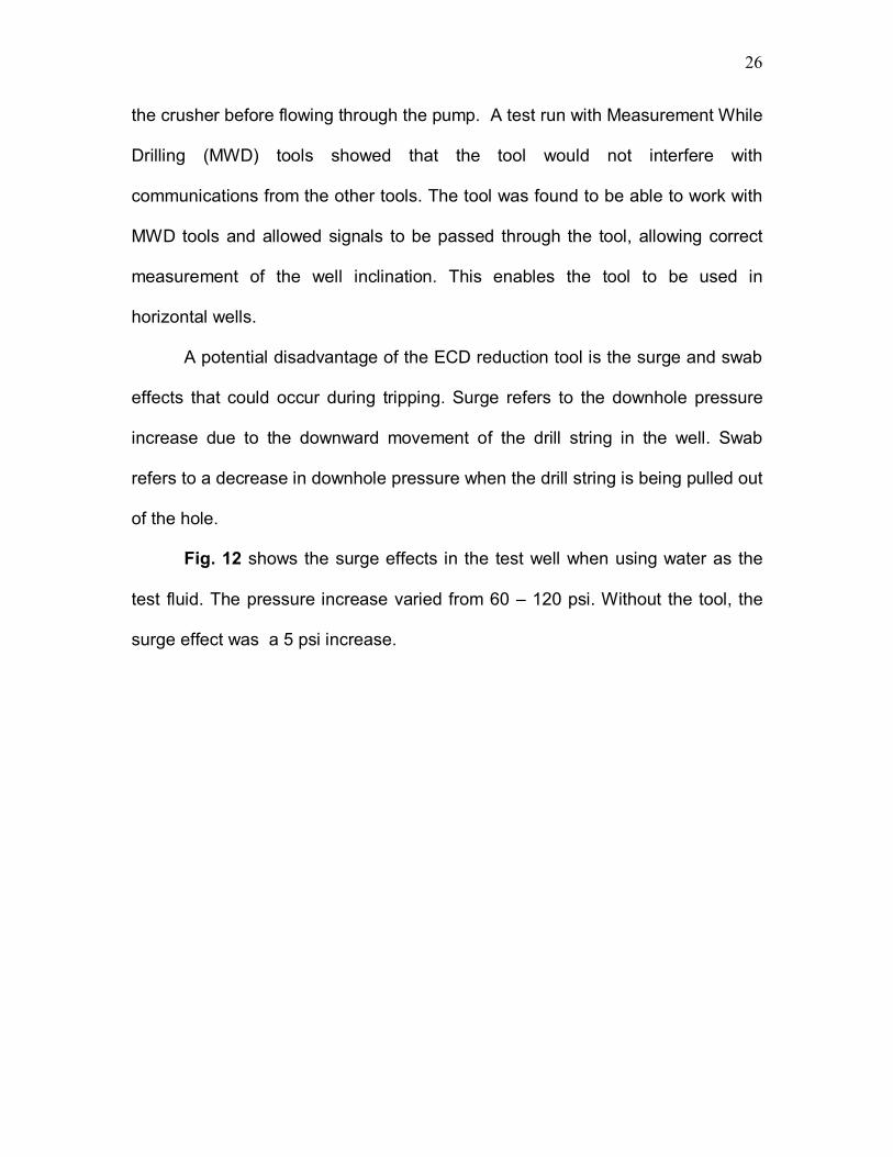
A potential disadvantage of the ECD reduction tool is the surge and swab
effects that could occur during tripping. Surge refers to the downhole pressure
increase due to the downward movement of the drill string in the well. Swab
refers to a decrease in downhole pressure when the drill string is being pulled out
of the hole.
Fig. 12 shows the surge effects in the test well when using water as the
test fluid. The pressure increase varied from 60 � 120 psi. Without the tool, the
surge effect was a 5 psi increase.

27
Fig. 12� Surge effect when tripping drillstring with ECD reduction (From Bern10).
Fig. 13 shows the swab effects as a result of running the ECD reduction
tool. The swab effect ranged from 20 to 150 psi. Without the tool, the swab effect
was only 10 to 15 psi. The reason for the high surge and swab is due to the large
casing size that was run in the test well. If the tool is run in small casing strings
the swab and surge effects will be lower.

28
Fig. 13� Swab effect when tripping drillstring with ECD reduction (From Bern10).
Fig. 14 shows the surge effects as a function of trip time per stand. The
surge pressure increased as trip time decreased. This is due to the increase in
pipe velocity while tripping into the hole.

29
Fig. 14� Surge effects as a function of trip time per stand(From Bern10).
When using the ECD reduction tool, it is important to consider the depth of
the zone of interest. As you can see in Fig. 7, the pressure is only reduced below
the location of the tool on the drillstring. This means that if the tool travels below
the zone of interest, then the tool will have no effect on the pressure at the zone
of interest.
The ECD reduction tool can be used in onshore and offshore
environments to help prevent problems associated with drilling wells that have
narrow pressure windows. It can help alleviate high ECD that could result in
formation damage and mud loss. It may be useful as a low cost alternative to
other ECD-reduction techniques. Further testing, though, is necessary to
determine if this tool can be used in smaller drillstrings and to further study the
effects of the tool on the surge and swab while tripping pipe.
30
Pressurized Mud Cap Drilling The pressurized mud cap drilling technique (PMCD) is used when dealing
with reservoirs that could result in a severe loss of circulation.12 Depleted
reservoirs, which have lower reservoir pressures because of the production from
other wells, often have circulation loss. If the reservoir pressure is significantly
lower than the wellbore pressure necessary to drill the well, the lost circulation
can be severe. As the mud is lost into the depleted zone, the hydrostatic
pressure of the wellbore decreases to balance the reservoir pressure at the
depleted zone. At this point, the wellbore pressure is below the reservoir
pressure of a zone that is not as deep as the loss zone. This causes gas to begin
to flow into the wellbore. One way to keep such a well under control is to fill up
the well at a rate that exceeds the gas percolation rate.12 The PMCD method
uses a heavier mud pumped down the annulus to keep the gas influx from
reaching the rig floor.
Fig. 15 shows the pressure profile of the pressurized mud cap method. A
lighter mud is used to drill the depleted section and the heavier mud forces the
fluid into the loss zone. Drilling continues and all the lighter mud and any influx is
forced into the depleted zone. This method keeps the well under control even
though all returns go to the depleted zone.

31
Fig. 15� Pressure-gradient profile for pressurized mud cap drilling method (From Hannegan6).
Hannegan13 found that PMCD also can work well when drilling in high-
pressure, fractured zones. In the Austin chalk, conventional mud-cap drilling had
been used for many years. In this method, mud that is several ppg heavier than
the formation pressure is used in the annulus. The mud balances the reservoir
pressure at a minimal volume, but results in an annular fluid level at an
uncontrollable depth. A disadvantage of this method is that it does not allow the
rig to monitor the downhole pressure directly. If gas breaks through the mud cap,
it is difficult to detect and would reach the surface with little warning. This could
TVD
psi
HIGH DENSITYFLUID
PRESSURIZED MUDCAP MPD
LOW DENSITYFLUID, E.G., SEAWATER BHP
EQUIVALENT SINGLEDENSITY GRADIENT
ALL RETURNSINJECTED INTO
LOSS ZONE
BP
TVD
psi
TVD
psipsi
HIGH DENSITYFLUID
PRESSURIZED MUDCAP MPD
LOW DENSITYFLUID, E.G., SEAWATER BHP
EQUIVALENT SINGLEDENSITY GRADIENT
ALL RETURNSINJECTED INTO
LOSS ZONE
BP

32
result in surface pressures that are above the rated working pressures of the
rotating control equipment.
Drilling in a high pressure reservoir, the difference between the drilling
fluid density and the reservoir fluid equivalent density can cause rapid increases
in overbalance at the bit.13 Fracture-zone pressures in the well can be drastically
different if some zones are depleted by other wells through an extensive fracture
system. With these different pressures throughout the wellbore, reservoir fluid
could flow in and mix with the cap mud, and cross-flow between the fracture
zones is possible. The cap mud could become severely overbalanced and cause
loss of the cap mud into the fractures.
The PMCD method12 solves this problem by keeping the pressure of the
cap mud at or just under the lowest reservoir pressure. The reservoir is now
controlled by the pressure caused by the column of mud with the addition of
surface pressure. The mud cap keeps control of the reservoir pressure
regardless of what is happening with each of the fracture zones. This prevents
loss of the cap mud into the fracture zones due to overbalance. The rig can also
directly monitor the pressure.
The important aspects of PMCD are the RCD, cap mud, and drilling fluid.
The RCD enables the operator to pump the cap mud into the annulus and to also
keep pressure at the surface to compensate for the lower mud weight of the
drilling fluid used to control the reservoir pressure during PMCD.12 The cap mud
needs to be the right kind for the specific job. The following are requirements for
the selection of the cap mud. 13

33
• Nondamaging to the formation.
• Not able to form damaging emulsions with either reservoir fluid or
drilling fluid.
• High rheology downhole to minimize mixing with reservoir fluids.
• Mixable in high volume.
• Able to be weighted up quickly during drilling operations.
• Inexpensive.
• The drilling fluid should be an inexpensive fluid that can be lost into
the formation at large volumes and also be compatible with the cap
mud.
The advantage of the PMCD method is that it can keep the well under
control even while suffering severe losses to the formation. The rig is still
protected by two barriers, the BOPs and the mud cap. Using a lighter drilling fluid
also increases the rate of penetration (ROP) and the lighter mud costs less than
the mud that would be lost in conventional drilling. Also another advantage with a
lighter fluid is that drilling is underbalanced, resulting in less damage to the
reservoir.
Controlled Mud Cap System
A newer drilling concept that is still being tested is the controlled mud cap
system (CMC).3 This system is similar to the pressurized mud-cap system,
except that the level of the mud cap is adjusted by a mud pump to better manage
the bottom hole pressure.

34
Fig. 16 shows a basic setup of this system for a well being drilled in
deepwater. A 12.5-in. ID riser is run. A subsea mudlift-pump is connected to the
riser by a riser-outlet joint. The outlet joint has high-pressure valves that enable it
to isolate the pump system from the riser. The pump is connected to the mud pits
by a return and a fill line. This allows the pump to increase or decrease the
amount of mud in the riser. To determine the level of the mud in the riser,
pressure sensors are located throughout the riser. The drilling riser is filled with
air above the mud cap.

35
Fig. 16�Controlled mud cap setup (From Juvkam-Wold5).
Pump
VariableRiser Fluid Level
SSBOP
SBOP
14-in HP Riser

36
The basic concept of this system is to compensate for ECD and thus
manage the BHP. In single-phase flow, to compensate for friction pressure
fluctuations related to factors such as pipe connections and circulation rate, the
height of mud in the riser will be adjusted. This system enables a driller to
compensate for ECD at a specific depth in the open hole section. Fossil3 built a
scale model to test the CMC system with single-phase flow. The mudlift pump in
the model was controlled by a downhole pressure recorder. The pump was set to
run at a specific BHP. The pump adjusted the level of mud in the riser to keep a
constant BHP regardless of the circulation rate, the amount of solids in the
annulus, or the RPM rate of the drill string.3
For multiphase flow, Jenner3 is currently working on a simulator to
calculate the pressure profile throughout the wellbore annulus. This simulator is
also being designed to predict the amount of hydrocarbons in the drilling riser as
a function of time to prepare the crew to take the necessary action.
This system also is unique in that it can be operated as either an open or
closed system. The first advantage to an open system is that it needs no
continuous closure elements to trap pressure in the well.3 This comes in handy
when considerable rig movement can affect the downhole pressure control. This
effect can occur when slips are set to make a pipe connection. With the CMC
system, the downhole pressure regime will generally be the same as in
conventional drilling except the mud weight may be higher and part of the drilling
riser may be filled with gas.

37
The second advantage with an open system is that a �positive� riser
margin can be designed to be included in this system.3 With this system the
hydrostatic pressure in the riser at sea level can be designed to equal or be less
than seawater pressure. This means a positive riser margin can be added with
no overbalance in the well. This positive riser margin means that if the riser was
to disconnect, the BHP would increase thus improving well control.
The third advantage is the CMC system�s ability to handle hydrocarbons.
The system operates as an open system until one of the rams of the surface
BOP is closed. Since this system acts as an open system with gas pressure
close to ambient, the drilling riser effectively becomes the hydrocarbon
separator.3 The gas is separated in the riser and the liquids are transported
through the pump system up to the rig. Being able to regulate the mud level while
this happens enables fast and accurate changes to the BHP.
If a well control problem arises, the system is designed to adjust to
compensate for the change. The subsea BOP would be closed. The mud level in
the riser would be increased to compensate for the fact that the pumps are shut
down and brought even higher to stop the influx or increase till it brings the
pressure close to the maximum allowable annulus shut-in pressure. The RCD at
the surface would be closed, but the choke line would be open to minimize the
pressure in the gas phase in the riser. The gas that remains in the riser can be
bled off to the atmosphere via the choke manifold. This procedure could be
performed in a very short time frame.

38
The main challenge with this system is to compensate for the hydrostatic
pressure that is caused by the standing column of mud in the drill pipe. Having a
full column of mud with the subsea BOP closed would cause the BHP to become
higher than the fracture pressure. This is due to the system using a higher mud
weight than is used in conventional drilling. A u-tube effect occurs where the mud
in the drill pipe flows into the annulus until the pressure equalizes between the
annulus and the drill pipe. One way to neutralize this effect is to have a pressure
differential valve in the drill string. The valve would be open at a predetermined
pressure and compensate for the static imbalance between the drill pipe and the
annulus. The valve would be closed if the pressure in the annulus is lower than
the pressure in the drill pipe. This blocks the annulus from being affected by the
standing column of mud when the subsea BOP is closed.
To show the advantages of CMC, Jenner3 ran two cases to show how
much gas each method can circulate out of the well without fracturing the
weakest formation in the open hole. This is referred to as kick margin (KM). Both
cases are for wells that are vertical and in 4100 ft of water depth. The tests also
assumed that the weakest formation is at the top of the openhole section and the
influx is bubble flow. Case 1 involves drilling an 8-1/2-in. hole from the casing
shoe at 7550 ft to 12500 ft.3
Table 5 shows the results of Case 1. The differential pressure between
fracture pressure and borehole pressure at the casing shoe is significantly higher
for the CMC method. This means that the operating window for the CMC method
is larger. The kick margin is also higher, meaning that this method can handle a
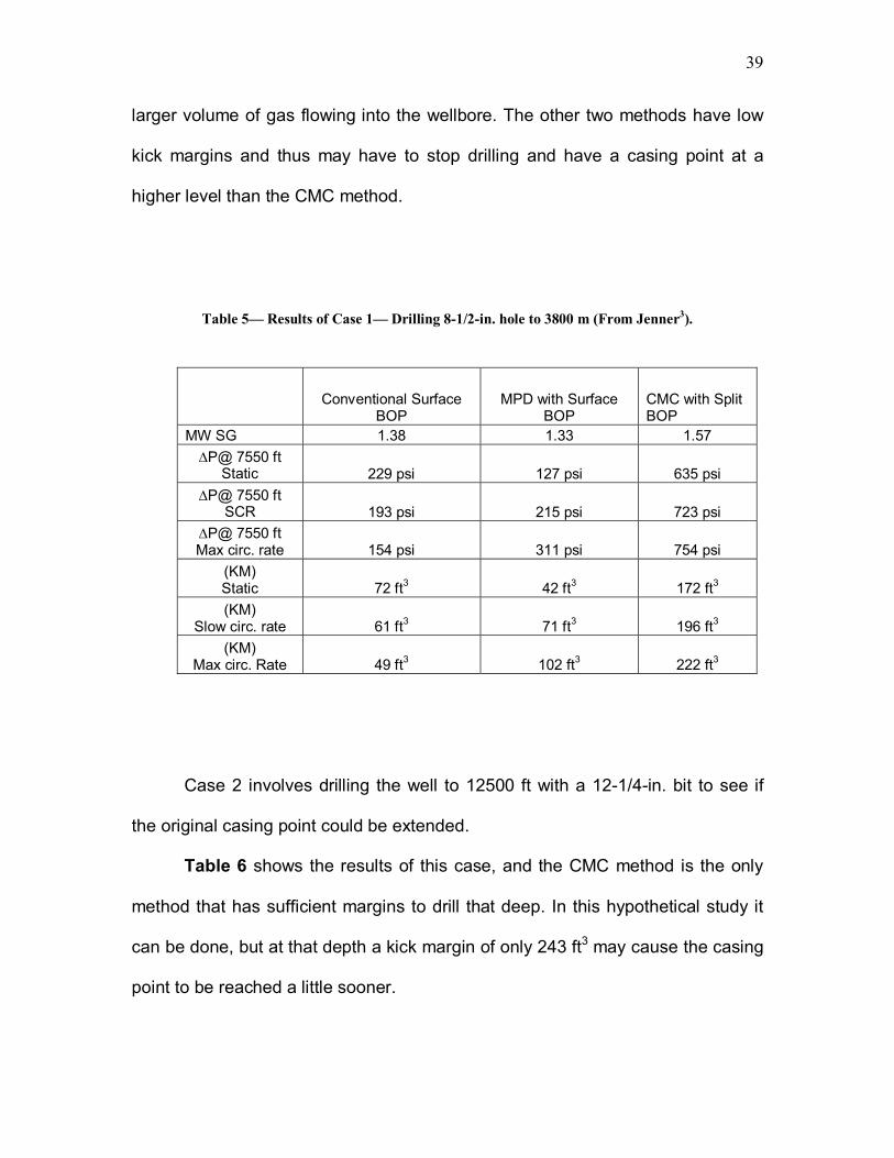
39
larger volume of gas flowing into the wellbore. The other two methods have low
kick margins and thus may have to stop drilling and have a casing point at a
higher level than the CMC method.
Table 5� Results of Case 1� Drilling 8-1/2-in. hole to 3800 m (From Jenner3).
Conventional Surface
BOP MPD with Surface
BOP CMC with Split BOP
MW SG 1.38 1.33 1.57 ∆P@ 7550 ft
Static 229 psi 127 psi 635 psi ∆P@ 7550 ft
SCR 193 psi 215 psi 723 psi ∆P@ 7550 ft Max circ. rate 154 psi 311 psi 754 psi
(KM) Static 72 ft3 42 ft3 172 ft3 (KM)
Slow circ. rate 61 ft3 71 ft3 196 ft3 (KM)
Max circ. Rate 49 ft3 102 ft3 222 ft3
Case 2 involves drilling the well to 12500 ft with a 12-1/4-in. bit to see if
the original casing point could be extended.
Table 6 shows the results of this case, and the CMC method is the only
method that has sufficient margins to drill that deep. In this hypothetical study it
can be done, but at that depth a kick margin of only 243 ft3 may cause the casing
point to be reached a little sooner.

40
Table 6� Results of Case 2� Drilling 12-1/4" hole to 3800 m (From Jenner3).
Conventional Surface
BOP MPD with Surface
BOP CMC with Split BOP
MW SG 1.38 1.33 1.57
∆P@ 6360 ft Static - 110 psi -160 psi 392 psi
∆P@ 6360 ft SCR - 124 psi - 137 psi 415 psi ∆P@ 6360 ft Max circ. rate - 148 psi - 97 psi 460 psi
(KM) Static 0 0 210 ft3 (KM)
Slow circ. rate 0 0 223 ft3 (KM)
Max circ. Rate 0 0 243 ft3
This method has many advantages. A driller is able to control downhole
pressure almost instantaneously by adjusting the height of mud in the riser.
Hydrocarbon influxes can be controlled and circulated out with ease. This system
also can act as either a closed or open system, depending on what is needed.

41
Dual-Gradient Drilling Method
Dual-Gradient drilling6 refers to drilling with two different fluid-density
gradients.
Fig. 17 shows the dual-gradient pressure profile. In this case, using a
single density fluid for this wellbore will cause the wellbore pressure to exceed
the formation pressure and result in lost circulation. With dual-gradient drilling, a
lighter fluid is used in the upper portion of a wellbore and a heavier fluid at the
lower portion. This enables the pressure to remain in the pressure window
between the pore pressure and fracture pressure.
Fig. 17� Dual-gradient drilling pressure gradient profile (From Hannegan6).
TVD
psi
SINGLE DENSITYGRADIENT
DEEPWATER DUAL GRADIENT MPD
DUAL DENSITYGRADIENT
BHP
Note: Dual gradient systems open margins in low overburden or quickly increasing pore pressure environments.
TVD
psi
SINGLE DENSITYGRADIENT
DEEPWATER DUAL GRADIENT MPD
DUAL DENSITYGRADIENT
BHP
TVD
psi
TVD
psipsi
SINGLE DENSITYGRADIENT
DEEPWATER DUAL GRADIENT MPD
DUAL DENSITYGRADIENT
BHP
Note: Dual gradient systems open margins in low overburden or quickly increasing pore pressure environments.

42
To achieve a dual gradient, a less-dense fluid such as air, inert gas, or
light liquid is injected at a certain point in the wellbore. Introducing this less-
dense fluid at this point would decrease the density of the fluid from that point up
to the surface. Another technique is used for offshore environments. A small-
diameter return line is run from the seafloor to circulate the drilling fluid and
cuttings. The marine riser is kept full of seawater. A subsea pump is used to lift
the drill cuttings and the drill fluid from the wellbore annulus up to the rig floor. By
using seawater in the marine riser, a more dense mud is used in the wellbore to
achieve the bottomhole pressure required.
The purpose of dual-gradient drilling is to prevent a large overbalance and
prevent exceeding the fracture gradient. Dual-gradient drilling allows the operator
to manipulate the pressure profile to prevent exceeding the fracture pressure at a
point but still to remain above the pore pressure. It is basically being able to take
a tight pressure gradient window and design a drilling plan to manipulate the
pressure curve to fit into the window.
Dual-gradient drilling can also be achieved in deep water without a riser
when first starting a subsea drilling location. A subsea RCD and remote
operating vehicle are used. The ROV is able to adjust backpressure at the
mudline by adjusting the choke. If the ROV closes the subsea choke, the BHP
increases. This results in drilling with a slight overbalance as if a marine riser
filled with drilling fluid were present. The advantage of being able to drill with a
slight overbalance is that it helps to prevent shallow gas or water flow. The
seawater is used as the drilling fluid so the drilling fluid and cuttings can be left

43
on the sea floor. Fig. 18 shows the pressure profile for this example and how
adding the backpressure at the seafloor causes the pressure profile to equal that
which would be achieved by having a single gradient.
Fig. 18�Pressure profile for drilling dual gradient without a riser (From Hannegan6).
A similar variation of dual-gradient drilling can be seen in Fig. 19. Zero-
discharge dual-gradient drilling involves using a subsea pump to return the
cuttings to the rig floor for disposal. It uses a riserless setup but has a line
through which the cuttings can be pumped to the rig floor. The BHP can be
adjusted by backpressure on the annulus or by adjusting speeds of the pumps.
TVD
psi
SINGLE DENSITYGRADIENT EQUIVALENT
RISERLESS MPD
SEAWATERGRADIENT
BP
MUDLINE
AFPTVD
psi
TVD
psipsi
SINGLE DENSITYGRADIENT EQUIVALENT
RISERLESS MPD
SEAWATERGRADIENT
BP
MUDLINE
AFP

44
Fig. 19� Pressure profile for riserless dual gradient drilling with zero discharge (From Hannegan6).
TVD
psi
SINGLE DENSITYGRADIENT EQUIVALENT
ZERO DISCHARGE RISERLESS MPD
FP
MUDLINE
Pump Head
TVD
psi
TVD
psipsi
SINGLE DENSITYGRADIENT EQUIVALENT
ZERO DISCHARGE RISERLESS MPD
FP
MUDLINE
Pump Head

45
As far as well control with dual-gradient drilling is concerned, the detection
criteria of a kick are very similar to conventional drilling. With dual-gradient
drilling, pressure gauges installed on the rig floor are more sensitive to changes
than the gauges used in conventional drilling. A decrease in circulating pressure
caused by an increase in flow will be more easily seen. If a kick occurs, the
annular flow rate of the drilling fluid will increase by an amount equal to the influx
rate.14 If the subsea pump were set to operate at a constant inlet pressure, the
subsea pump rate would increase. This increase would be seen on the
computers at the rig floor and would give a good indication of a kick. The
procedures used to circulate the kick out are very similar to the ones used in
conventional drilling.

46
FUTURE OF MANAGED PRESSURE DRILLING
In applying MPD in the field, many variations6 are still being developed.
Using compressible fluids with MPD is an interesting variation that would allow
drilling with a balanced pressure using air, mist, or foam.6 This could result in
increasing ROP when drilling while still keeping the pressure inside the gradient
window.
Another variation is having the ability to strengthen the wellbore using
solids in the mud to plug and support microfractures that can form in weaker
formations when using a higher density mud.6 This variation would not be
adjusting the pressure gradient of the wellbore but would widen the window so
that the well could be drilled successfully.
The challenge for the future of MPD is to convince the industry of its
benefits. The best way to do this is to have companies run tests out in the
offshore environment to prove that these techniques work. A few companies
have already used a couple of the techniques when drilling offshore. In 2004, a
company used PMCD to help in a formation that was well known for losing
drilling fluid.6 The technique was able to reduce the amount of drilling fluid lost
and decrease non-productive time. In 2001, a dual-gradient well was drilled in
the Gulf of Mexico.6 It used an RCD with a subsea pump to pump the cuttings
and drilling fluids up to the rig through lines run down to the seafloor. Its purpose
was to show that dual-gradient drilling could be used in all phases of the drilling
program. This is a good start to showing companies that MPD can work offshore.
47
The main problem in instituting MPD is that companies think that their way
works well enough and do not want to take the risk of trying a newer method.
This is similar to situations that occurred when underbalanced drilling and
horizontal drilling were first introduced. It is just going to take time for MPD to
become an accepted method and be used in regular drilling operation.
The benefits that should be shown to companies at this time to convince
them to try MPD include the possibility of improving the drill-ability of depleted
formations. Brownfields are fields that are mature and have produced for many
years.15 These fields hold much of the remaining reserves in the U.S. Due to the
production throughout the years in these fields, drilling through production zones
that no longer have virgin pore pressure is required. Drilling through these
depleted zones often result in narrow pressure windows and lost circulation
issues. Drilling in these areas require a more constant bottomhole pressure to
remain in the narrow pressure window. MPD would help reduce costs and
improve current assets held by companies. Companies realizing these benefits
and seeing them work would lead to more common use by these companies.
A company can also look at the history of a field to determine if MPD
would help the company. Looking at the drilling history and seeing the NPT will
show a company what problems they have that occur during drilling. A statistical
study of economics showing how reducing these problems using MPD can
improve the economics of a well will help companies make the switch to using
MPD while drilling.

48
CONCLUSIONS
• Managed pressure drilling is a new technology that will improve the
economic drillability of wells. It can help solve many of the problems
that result from pressure variations in the formations. It will increase
reserves for companies by enabling drilling of areas that were
previously economically undrillable.
• MPD uses tools similar to those that are being used for
underbalanced drilling; this could mean a smoother transition for
companies to begin using MPD technology. Many variations of
MPD are available, but more research is necessary to determine
which variation is best to be used in specific drilling situations.
• The ECD reduction tool reduces the dynamic pressure profile of a
well from the point where the tool is installed on the drill string to
the bottom of the hole. This tool may not be ideal in a deep well
where narrow pressure margins are located at shallow depths. If
the tool passes the narrow pressure margin while drilling, the tool
would cease to have any effect on the pressure at that point. The
pressure could exceed the fracture pressure and cause lost
circulation.
• The Continuous Circulation System allows the pressure profile to
remain consistent when making connections. It prevents pressure
spikes that can occur when turning the pumps on and off. It is ideal

49
for situations where a well can remain in the pressure margins with
a specific mud weight in the drilling plan but could deviate out of the
pressure margins with pressure spikes while making connections.
• Pressurized Mud Cap Drilling is an ideal MPD method for wells that
have severe circulation loss. These usually include wells that are
being drilled in depleted formations with reduced pressure. This
method improves the economics of drilling with severe lost
circulation by using a drill fluid that is less dense and can be lost to
the formation. A heavier mud above the point of lost circulation
provides the pressure necessary to force mud into the depleted
formation. It also allows a driller to keep control of a well even if
suffering severe losses.
• Controlled Mud Cap drilling is a newer technology that allows the
driller to adjust the pressure by changing the level of mud in the
riser. By adjusting the level of mud, the pressure profile throughout
the well changes. This is ideal for areas in which a driller is not sure
of the exact pressure gradients. A driller can start drilling and see if
there are pressure problems and lower or raise the mud level as
needed to keep the well within the pressure margins.
• Dual-Gradient Drilling uses two different drilling fluids during drilling
to create a pressure profile that has two gradients. This is good for
situations in offshore drilling where using one fluid throughout the
wellbore would cause the pressure to exceed the fracture gradient.

50
A less dense fluid can be used to fill the marine riser and then a
heavier fluid can be used as the drilling fluid and fill the wellbore
from sea level to the bottom of the hole. This creates two gradients
for the pressure profile of the well and would allow the driller to
design the well to be able to remain in the pressure window. This
method would prevent having a large over balance while drilling
and prevent exceeding the fracture gradient.
• MPD can solve many of the NPT problems that occur while drilling
offshore. By solving these problems, MPD can improve the
economics of drilling wells and enable the drilling of wells that
previously were thought to be uneconomical.

51
RECOMMENDATIONS
• Further research into the different variations of managed pressure
drilling is needed to see the exact effect that these variations have
on the pressure-gradient window. A better understanding of the
variations will help the industry in making decisions on which
variations they should use when drilling.
• A simulator needs to be designed to show the downhole effects that
occur when using MPD. An accurate simulator that can show
different situations that can occur while using the system will help in
the design of MPD techniques and choosing which techniques are
best to use in certain situations.
• A detailed economic study needs to be done on MPD techniques.
With economics being a controlling factor in deciding what methods
to use when drilling, a good study showing the economic benefits of
MPD would help companies make the decision to use MPD. This
economic study should look at the cost of the different techniques
and the expected savings a company would see by using these
techniques.

52
NOMENCLATURE AFP = Annular Friction Pressure
BHP = Bottom Hole Pressure
BOP = Blow Out Preventer
CMC = Controlled Mud Cap
ECD = Equivalent Circulating Density
HH = Hydrostatic Head
IADC = International Association of Drilling Contractors
KM = Kick Margin
MPD = Managed Pressure Drilling
MW = Mud Weight
NPT = Non-Productive Time
PMCD = Pressurized Mud Cap Method
RCD = Rotating Control Device
ROP = Rate of Penetration
TVD = True Vertical Depth
UBD = Underbalanced Drilling

53
REFERENCES 1. Coker, I.: �Managed Pressure Drilling Applications Index,� paper OTC
16621 presented at the 2004 Offshore Technology Conference, Houston,
3-6 May.
2. IADC Glossary of MPD terms, www.iadc.org, 11/2005.
3. Fossil, B., and Sangesland, S.: �Managed Pressure Drilling for Subsea
Applications; Well Control Challenges in Deepwater,� paper SPE 91633
presented at the 2004 SPE/IADC Underbalanced Technology Conference
and Exhibition, Houston, 11- 12 October.
4. Hannegan, D.: �Managed Pressure Drilling in Marine Environment- Case
Studies,� paper SPE 92600 presented at the 2005 SPE/IADC Drilling
Conference, Amsterdam, The Netherlands, 23- 25 February.
5. Juvkam-Wold, H.: Pete 411- Drilling class notes, 2005, Texas A&M
University.
6. Hannegan, D: �Managed Pressure Drilling,� SPE Advanced Drilling
Technology & Well Construction Textbook, Chp. 9, Section 10.
7. James K. Dodson Study, www.infogulf.com, 11/2005.
8. Jenner, J.W., Elkins, H.L., Springett, F., Lurie, P.G., and Wellings, J.S.:
�The Continuous Circulation System: An Advance in Constant Pressure
Drilling,� paper SPE 90702 presented at the 2004 SPE Annual Technical
Conference and Exhibition, Houston, 26- 29 September.

54
9. Kenawy, W.F.: �Continuous Circulation System: A New Enabling
Technology,� MS Thesis, Texas A&M University, College Station, Texas
(2002).
10. Bern, P. A., Armagost, W.K, and Bansal, R.K.: �Managed Pressure Drilling
with the ECD Reduction Tool,� paper SPE 89737 presented at the 2004
SPE Annual Technical Conference and Exhibition, Houston, 26- 29
September.
11. Oort, E., Roy, S., Zamora, M., and Toups, B.: �Real-Time Simulation and
Management using a Remote Operations Center,� paper SPE 92605
presented at the 2005 SPE/IADC Drilling Conference, Amsterdam, The
Netherlands, 23- 25 February.
12. Terwogt, J.H, and Gedge, B.J.: �Pressurized Mud Cap Drilling from a
Semi-Submersible Drilling Rig,� paper SPE 92294 presented at the 2005
SPE/IADC Drilling Conference, Amsterdam, The Netherlands, 23- 25
February.
13. Hannegan, D.: �Well Control Considerations- Offshore Applications of
Underbalanced Drilling Technology,� paper SPE 79854 presented at the
2003 SPE/IADC Drilling Conference, Amsterdam, The Netherlands, 19- 21
February.
14. Schubert, J.J. , Juvkam-Wold, H.C., and Choe, J.: �Well Control
Procedures for Dual Gradient Drilling as Compared to Conventional Riser
Drilling,� paper SPE 79880 presented at the 2003 SPE/IADC Drilling
Conference, Amsterdam, The Netherlands, 19- 21 February.

55
15. Hannegan, D.: �Brownfields applications for MPD,� E&P (October 2005)
45.

56
VITA
Name: Matthew Daniel Martin Address: 5540 Canyon Rd. #814 Benbrook, Tx 76126 Phone: 979-571-8712 Employer: XTO Energy Education: Texas A&M University, College Station, Tx M.S in Petroleum Engineering, May 2006 B.S. in Petroleum Engineering, May 2004