Embed Size (px)
Citation preview
Man-Made Accelerators(Earth-Based)
Ron RuthSLAC


Outline of Talk• Introduction• History of Particle Acceleration• Basic Principles
– What are the forces?– Acceleration and radiation– Synchronism– Basic device ideas, linear circular– Beams and physics– Storage ring colliders– Electron Linear Accelerators– The next window: linear colliders
• The present generation– Storage Ring Factories– LHC– Linear colliders: ILC
• The next generations– Two beam colliders– Laser acceleration– Plasma acceleration– Muon colliders
Cosmic Ray Spectrum
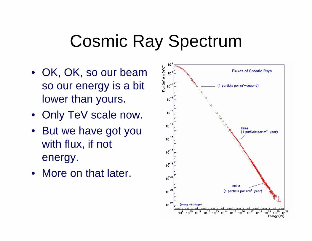
• OK, OK, so our beam so our energy is a bit lower than yours.
• Only TeV scale now.• But we have got you
with flux, if not energy.
• More on that later.
From ‘The Evolution of Particle Accelerators and Colliders’ by Wolfgang K. H. Panofsky
“WHEN J. J. THOMSON discovered the electron, he did not call the instrument the was using an accelerator, but an accelerator it certainly was. He accelerated particles between two electrodes to which he had applied a difference in electric potential. He manipulated the resulting beam with electric and magnetic fields to determine the charge-to-mass ratio of cathode rays. Thomson achieved his discovery by studying the properties of the beam itself—not its impact on a target or another beam, as we do today. Accelerators have since become indispensable in the quest to understand Nature at smaller and smaller scales. And although they are much bigger and far more complex, they still operate on much the same physical principles as Thomson’s device.” [1897]
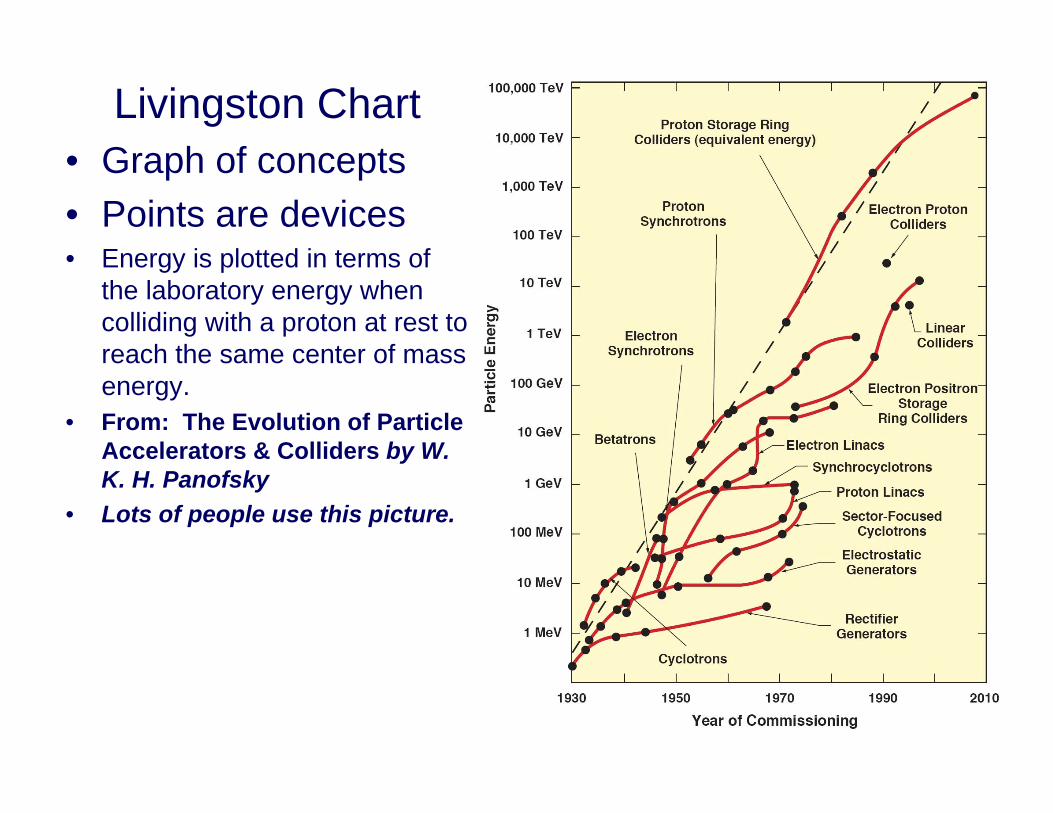
Livingston Chart• Graph of concepts• Points are devices• Energy is plotted in terms of
the laboratory energy when colliding with a proton at rest to reach the same center of mass energy.
• From: The Evolution of Particle Accelerators & Colliders by W. K. H. Panofsky
• Lots of people use this picture.
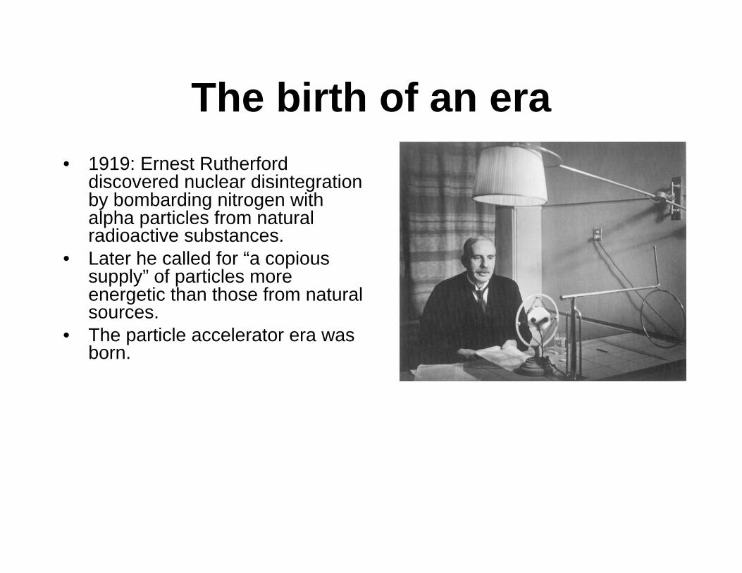
The birth of an era• 1919: Ernest Rutherford
discovered nuclear disintegration by bombarding nitrogen with alpha particles from natural radioactive substances.
• Later he called for “a copious supply” of particles more energetic than those from natural sources.
• The particle accelerator era was born.
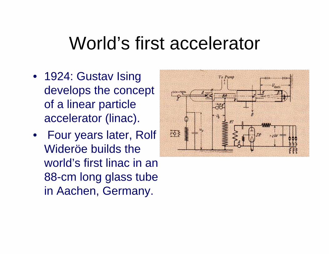
World’s first accelerator
• 1924: Gustav Isingdevelops the concept of a linear particle accelerator (linac).
• Four years later, Rolf Wideröe builds the world’s first linac in an 88-cm long glass tube in Aachen, Germany.
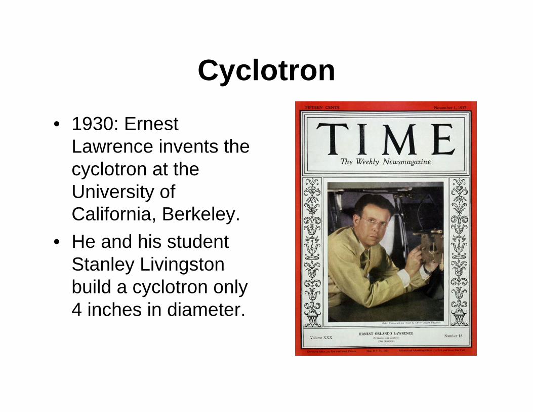
Cyclotron• 1930: Ernest
Lawrence invents the cyclotron at the University of California, Berkeley.
• He and his student Stanley Livingston build a cyclotron only 4 inches in diameter.
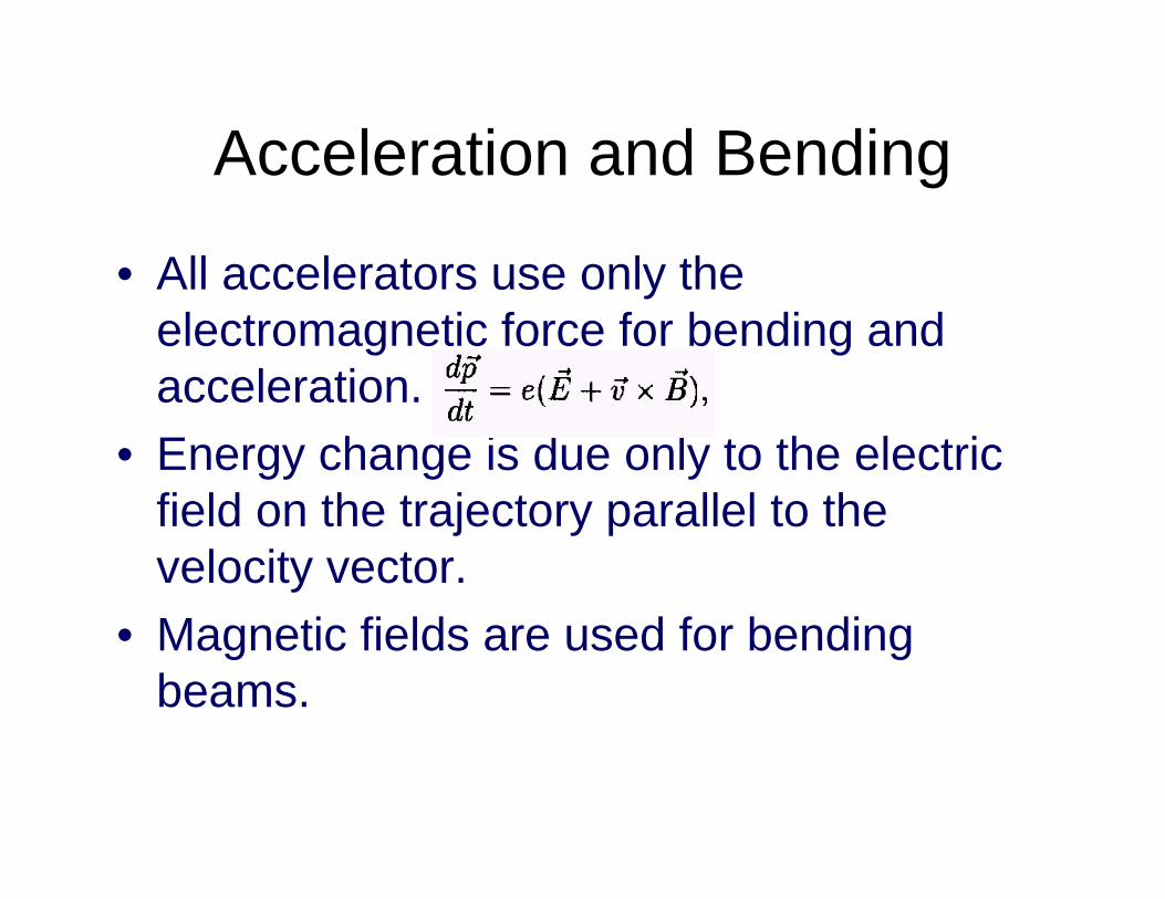
Acceleration and Bending
• All accelerators use only the electromagnetic force for bending and acceleration.
• Energy change is due only to the electric field on the trajectory parallel to the velocity vector.
• Magnetic fields are used for bending beams.
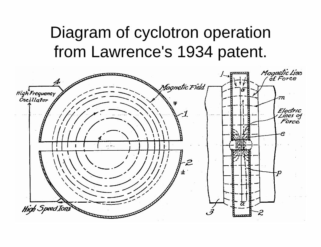
Diagram of cyclotron operation from Lawrence's 1934 patent.
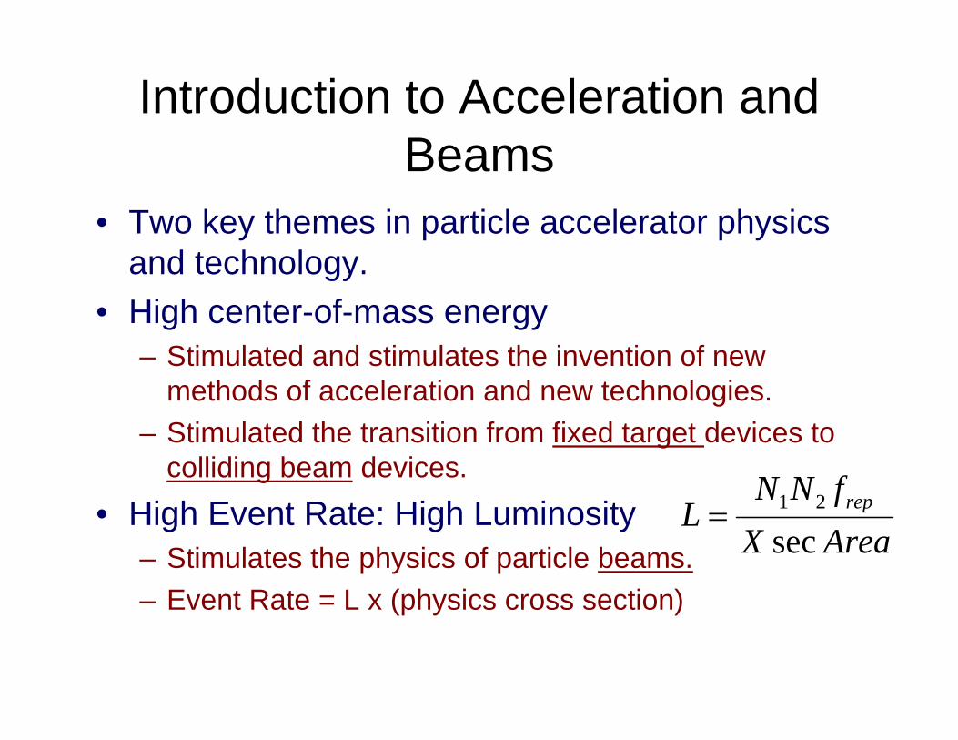
Introduction to Acceleration and Beams
• Two key themes in particle accelerator physics and technology.
• High center-of-mass energy– Stimulated and stimulates the invention of new
methods of acceleration and new technologies.– Stimulated the transition from fixed target devices to
colliding beam devices.• High Event Rate: High Luminosity
– Stimulates the physics of particle beams.– Event Rate = L x (physics cross section)
AreaXfNN
L rep
sec21=
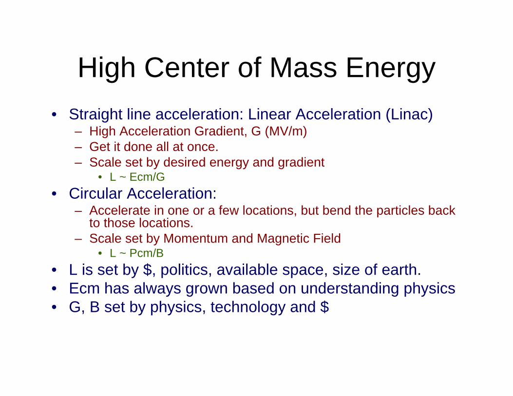
High Center of Mass Energy• Straight line acceleration: Linear Acceleration (Linac)
– High Acceleration Gradient, G (MV/m)– Get it done all at once.– Scale set by desired energy and gradient
• L ~ Ecm/G• Circular Acceleration:
– Accelerate in one or a few locations, but bend the particles back to those locations.
– Scale set by Momentum and Magnetic Field• L ~ Pcm/B
• L is set by $, politics, available space, size of earth.• Ecm has always grown based on understanding physics• G, B set by physics, technology and $
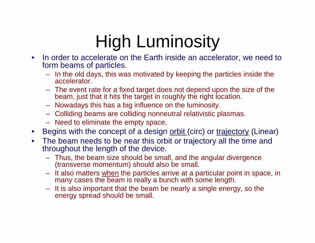
High Luminosity• In order to accelerate on the Earth inside an accelerator, we need to
form beams of particles.– In the old days, this was motivated by keeping the particles inside the
accelerator.– The event rate for a fixed target does not depend upon the size of the
beam, just that it hits the target in roughly the right location.– Nowadays this has a big influence on the luminosity.– Colliding beams are colliding nonneutral relativistic plasmas.– Need to eliminate the empty space.
• Begins with the concept of a design orbit (circ) or trajectory (Linear)• The beam needs to be near this orbit or trajectory all the time and
throughout the length of the device.– Thus, the beam size should be small, and the angular divergence
(transverse momentum) should also be small.– It also matters when the particles arrive at a particular point in space, in
many cases the beam is really a bunch with some length.– It is also important that the beam be nearly a single energy, so the
energy spread should be small.
High Center of Mass Energy• High Gradient: for linear accelerators/colliders
– Need to respect physics limits: breakdown– Need to get energy to the beam: Power source– Need efficiency– Technologies:
• Klystrons (power sources)• High frequency accelerators—High Gradient• Superconducting accelerators.
• High Magnetic Field: for circular accelerators/colliders– Technology: Superconducting Magnets
Colliding Beams vs Fixed Target
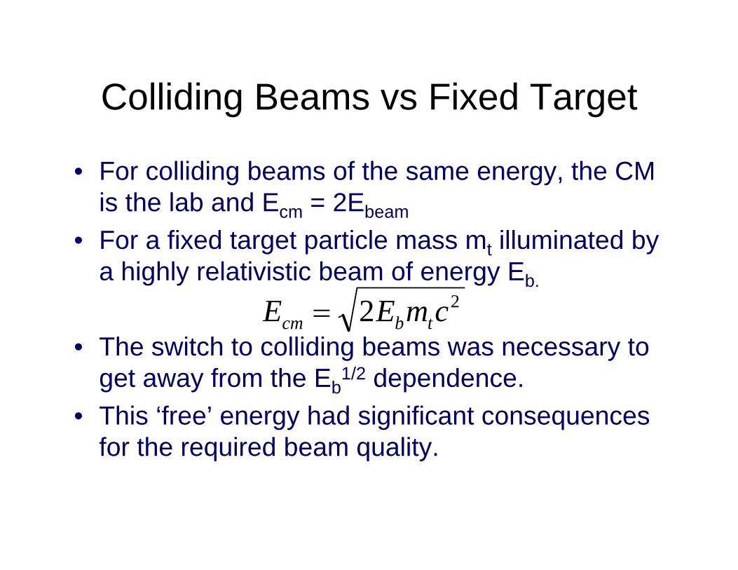
• For colliding beams of the same energy, the CM is the lab and Ecm = 2Ebeam
• For a fixed target particle mass mt illuminated by a highly relativistic beam of energy Eb.
• The switch to colliding beams was necessary to get away from the Eb
1/2 dependence.• This ‘free’ energy had significant consequences
for the required beam quality.
22 cmEE tbcm =
Particle Beams• So think of a reference particle defining the reference
trajectory or orbit and the reference time (or phase).• The beam deviates from this particle.
– Δpx, Δx, Δpy, Δy, ΔE, Δt, You may think of these as rms values.– There is a distribution in this 6 dimensional phase space.– Units of the volume = action3
– As the beam is accelerated, the volume is invariant (at best).• Usually divide momenta and energy to get relative
values.– During acceleration, the relative volume decreases, angles get
smaller and relative energy spread get smaller (ideally).– The quantities (ΔpiΔx)/p are called the emittances of the beam.– The density of the beam in this phase space is called the
brightness or brilliance, depending upon who you talk to.• Bright beams yield high luminosity and event rate.
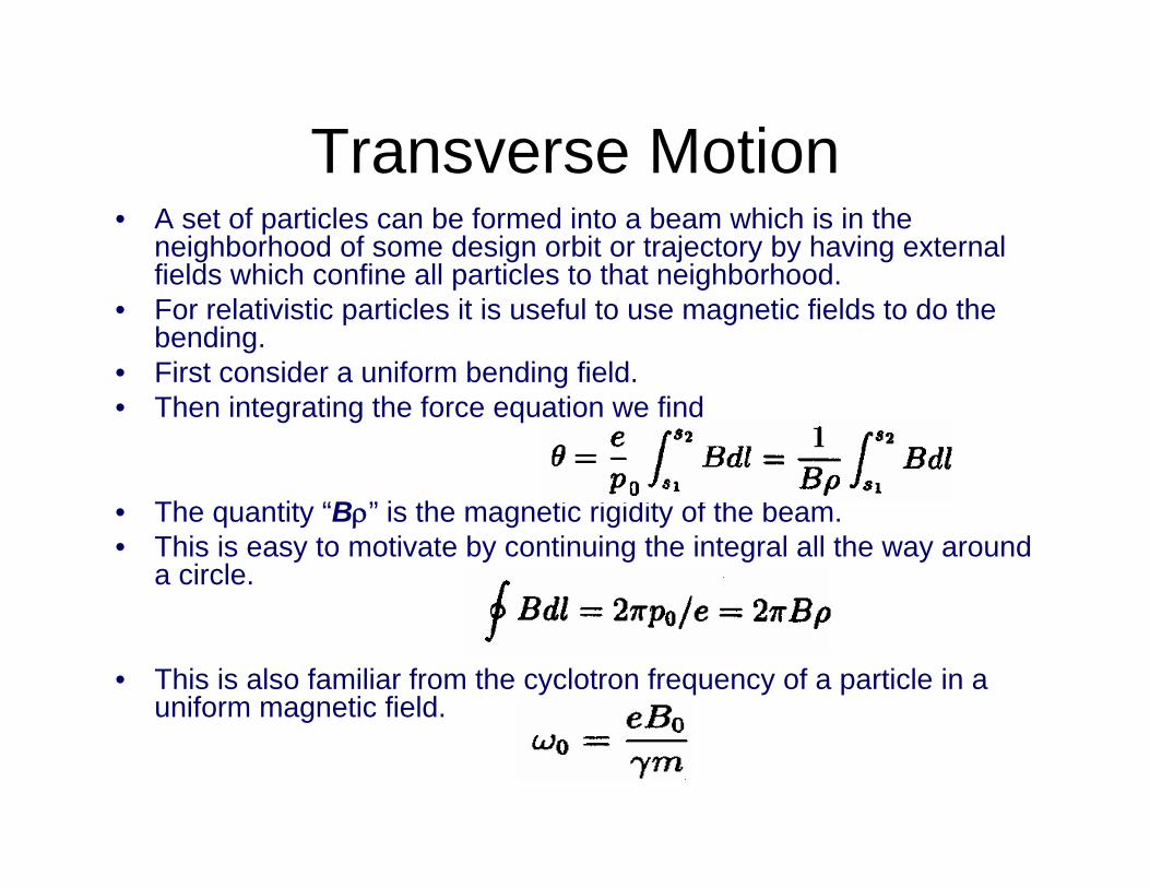
Transverse Motion• A set of particles can be formed into a beam which is in the
neighborhood of some design orbit or trajectory by having external fields which confine all particles to that neighborhood.
• For relativistic particles it is useful to use magnetic fields to do the bending.
• First consider a uniform bending field.• Then integrating the force equation we find
• The quantity “Bρ” is the magnetic rigidity of the beam. • This is easy to motivate by continuing the integral all the way around
a circle.
• This is also familiar from the cyclotron frequency of a particle in a uniform magnetic field.
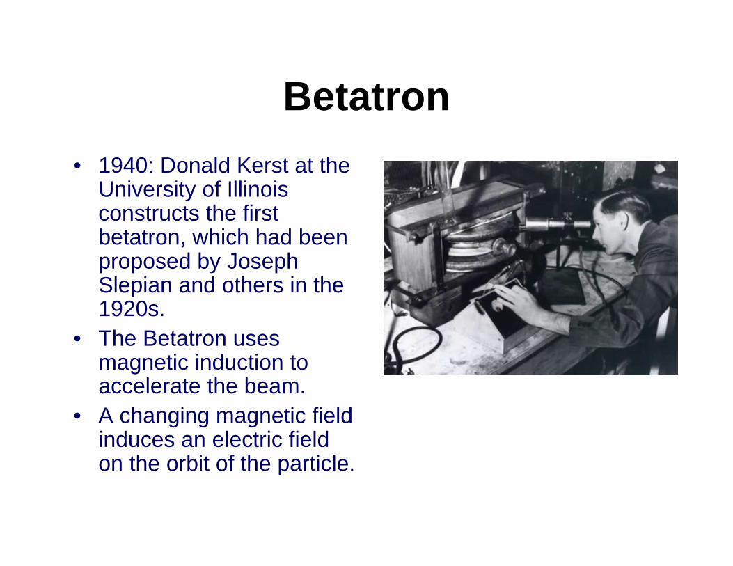
Betatron• 1940: Donald Kerst at the
University of Illinois constructs the first betatron, which had been proposed by Joseph Slepian and others in the 1920s.
• The Betatron uses magnetic induction to accelerate the beam.
• A changing magnetic field induces an electric field on the orbit of the particle.
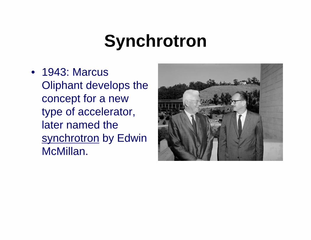
Synchrotron• 1943: Marcus
Oliphant develops the concept for a new type of accelerator, later named the synchrotron by Edwin McMillan.
Synchrotron Principles• Cyclotron: constant magnetic field and a constant-frequency applied
electric field (one of these is varied in the synchrocyclotron).• Synchrotron: both of these fields are varied. By increasing the
magnetic field and sometimes the frequency of the applied electric field, as the particles gain energy, their path can be held constant as they are accelerated. Provided that there is synchronism between the particle revolution frequency and the accelerator field, the beam accelerates and the magnetic field is increased. Phase Stability keeps the bunches of particles together.
• In modern synchrotrons using strong focusing, this allows the vacuum chamber to small and the magnets to be small in volume.
• Can divide the circumference into bending, focusing and some sections for acceleration.
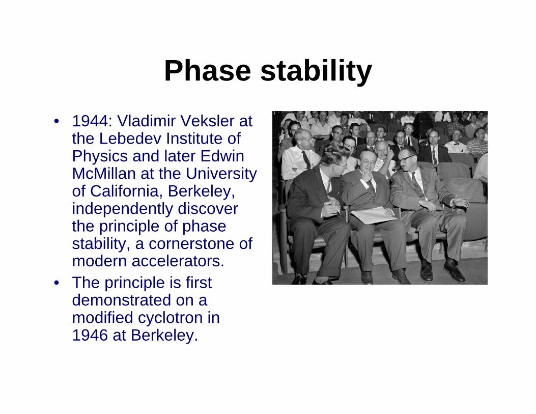
Phase stability• 1944: Vladimir Veksler at
the Lebedev Institute of Physics and later Edwin McMillan at the University of California, Berkeley, independently discover the principle of phase stability, a cornerstone of modern accelerators.
• The principle is first demonstrated on a modified cyclotron in 1946 at Berkeley.
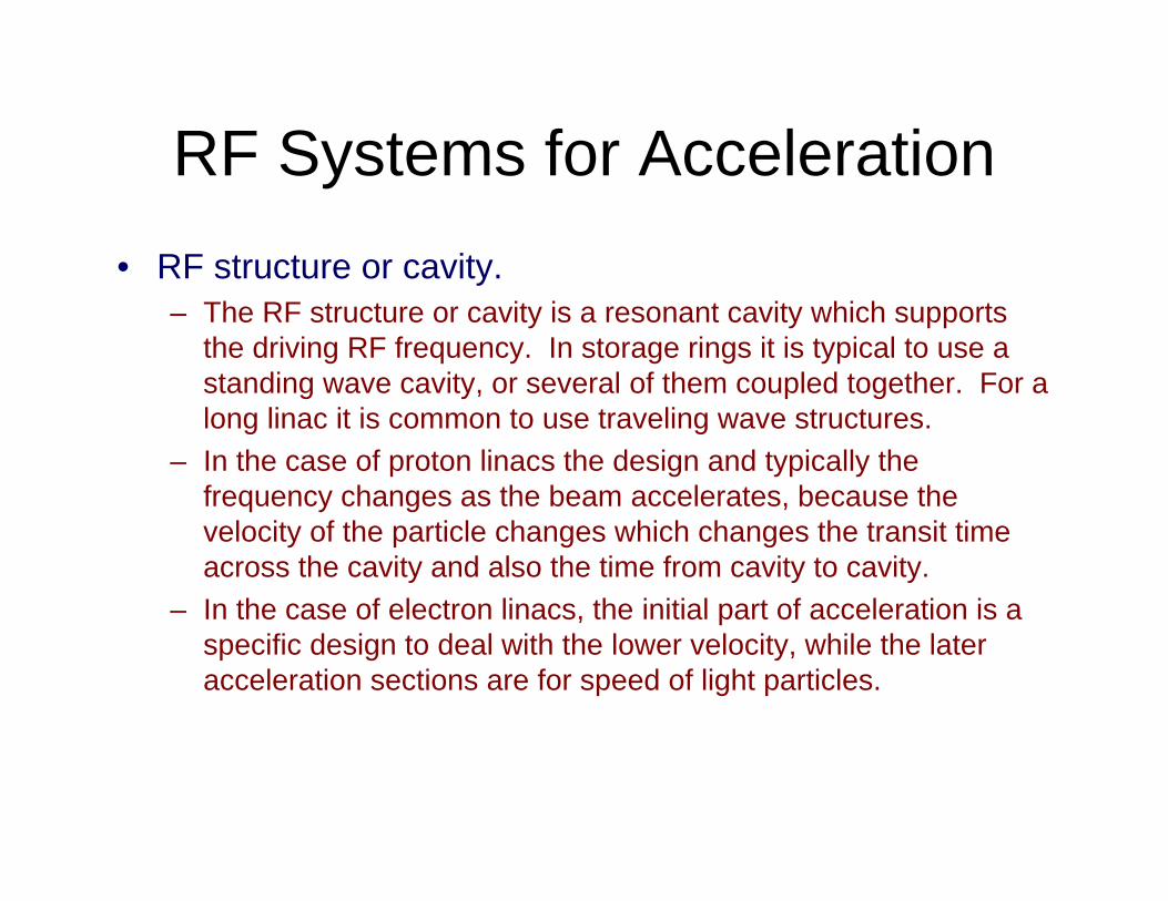
RF Systems for Acceleration• RF structure or cavity.
– The RF structure or cavity is a resonant cavity which supports the driving RF frequency. In storage rings it is typical to use a standing wave cavity, or several of them coupled together. For a long linac it is common to use traveling wave structures.
– In the case of proton linacs the design and typically the frequency changes as the beam accelerates, because the velocity of the particle changes which changes the transit time across the cavity and also the time from cavity to cavity.
– In the case of electron linacs, the initial part of acceleration is a specific design to deal with the lower velocity, while the lateracceleration sections are for speed of light particles.
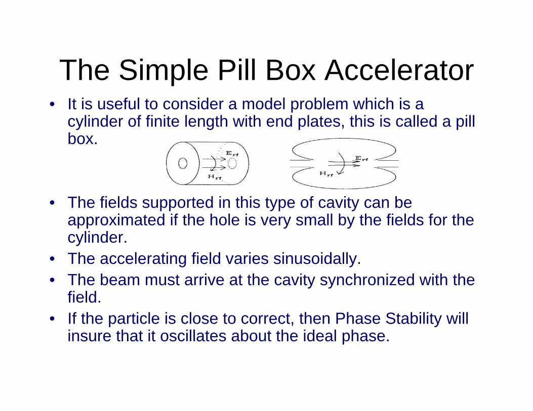
The Simple Pill Box Accelerator• It is useful to consider a model problem which is a
cylinder of finite length with end plates, this is called a pillbox.
• The fields supported in this type of cavity can be approximated if the hole is very small by the fields for the cylinder.
• The accelerating field varies sinusoidally.• The beam must arrive at the cavity synchronized with the
field.• If the particle is close to correct, then Phase Stability will
insure that it oscillates about the ideal phase.
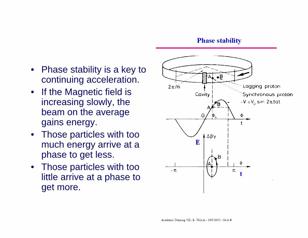
• Phase stability is a key to continuing acceleration.
• If the Magnetic field is increasing slowly, the beam on the average gains energy.
• Those particles with too much energy arrive at a phase to get less.
• Those particles with too little arrive at a phase to get more.
Transverse Stability• Beams are confined near the ideal trajectory
with quadrupole magnets or by magnetic field tapering in the old days.
• These magnets act just like lenses do to light, but they focus in one direction while defocusing in the other.
• If they are alternated, there is a net focusing.• This is just the alternating gradient principle for
Strong Focusing invented by Courant, Livingston, Snyder and Christofilos
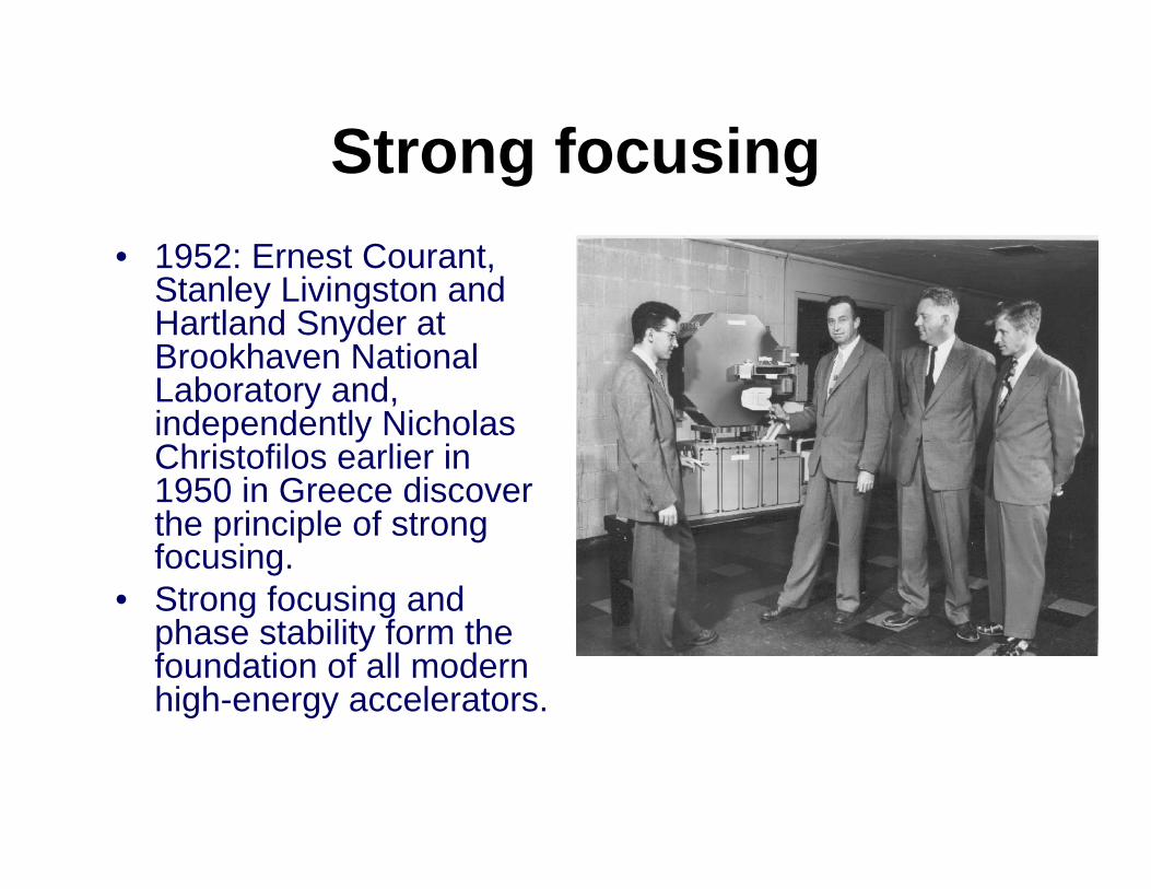
Strong focusing• 1952: Ernest Courant,
Stanley Livingston and Hartland Snyder at Brookhaven National Laboratory and, independently Nicholas Christofilos earlier in 1950 in Greece discover the principle of strong focusing.
• Strong focusing and phase stability form the foundation of all modern high-energy accelerators.
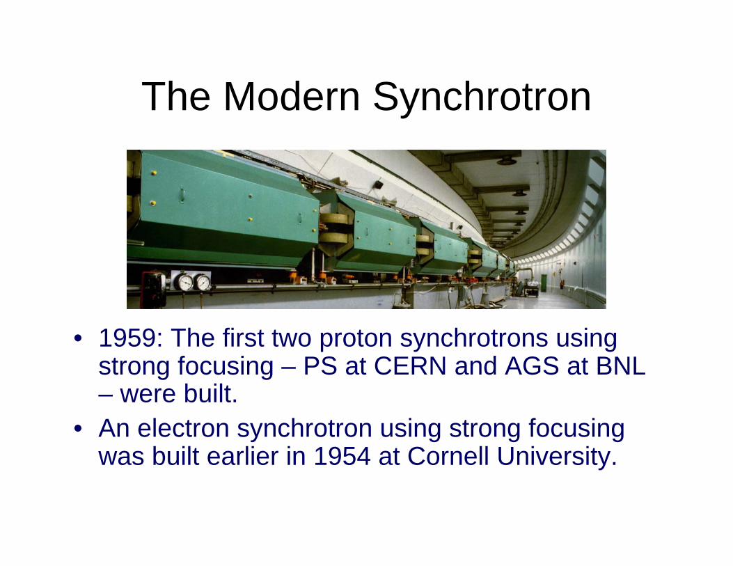
The Modern Synchrotron
• 1959: The first two proton synchrotrons using strong focusing – PS at CERN and AGS at BNL – were built.
• An electron synchrotron using strong focusing was built earlier in 1954 at Cornell University.
The Storage Ring Collider• The step from the synchrotron to the storage ring was a
natural one, but presented lots of challenges.• If you use the antiparticle colliding with the particle, then
you can use the same storage ring for both (magnetic bending)
• You have to make sure the don’t collide when you don’t want them to, so sometimes electrostatic deflectors have been used to separate beams to keep them from colliding.
• One key item is to decrease the beam size at the interaction point in increase the density there.
• Of course, if you have the same particle type, then you need to have two rings, one for each.
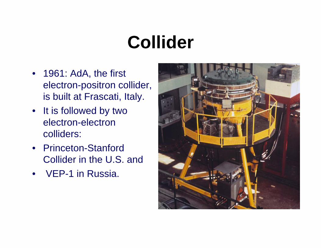
Collider• 1961: AdA, the first
electron-positron collider, is built at Frascati, Italy.
• It is followed by two electron-electron colliders:
• Princeton-Stanford Collider in the U.S. and
• VEP-1 in Russia.
Focusing to a small spot• Beams can be focused to a small spot in just the way
that light can be.• In this case, the smaller the beam size, the shorter the
depth of focus.• The small beam size needs larger divergence, and the
product of these two is just the ‘emittance’ discussed earlier.
• This larger divergence needs a large aperture for the preceding lens.
• It works the same for light.• All you camera buffs out there know all about that.
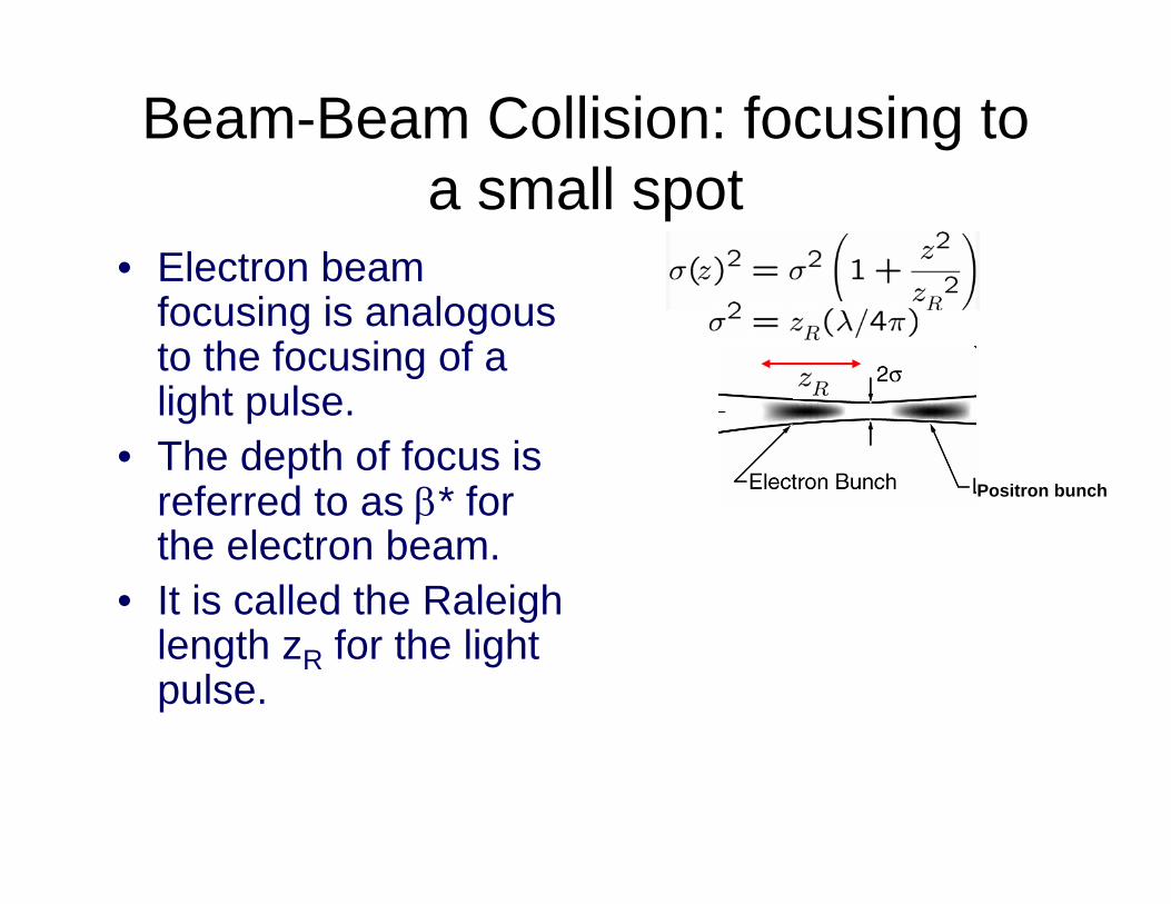
Beam-Beam Collision: focusing to a small spot
• Electron beam focusing is analogous to the focusing of a light pulse.
• The depth of focus is referred to as β* for the electron beam.
• It is called the Raleigh length zR for the light pulse.
Positron bunch
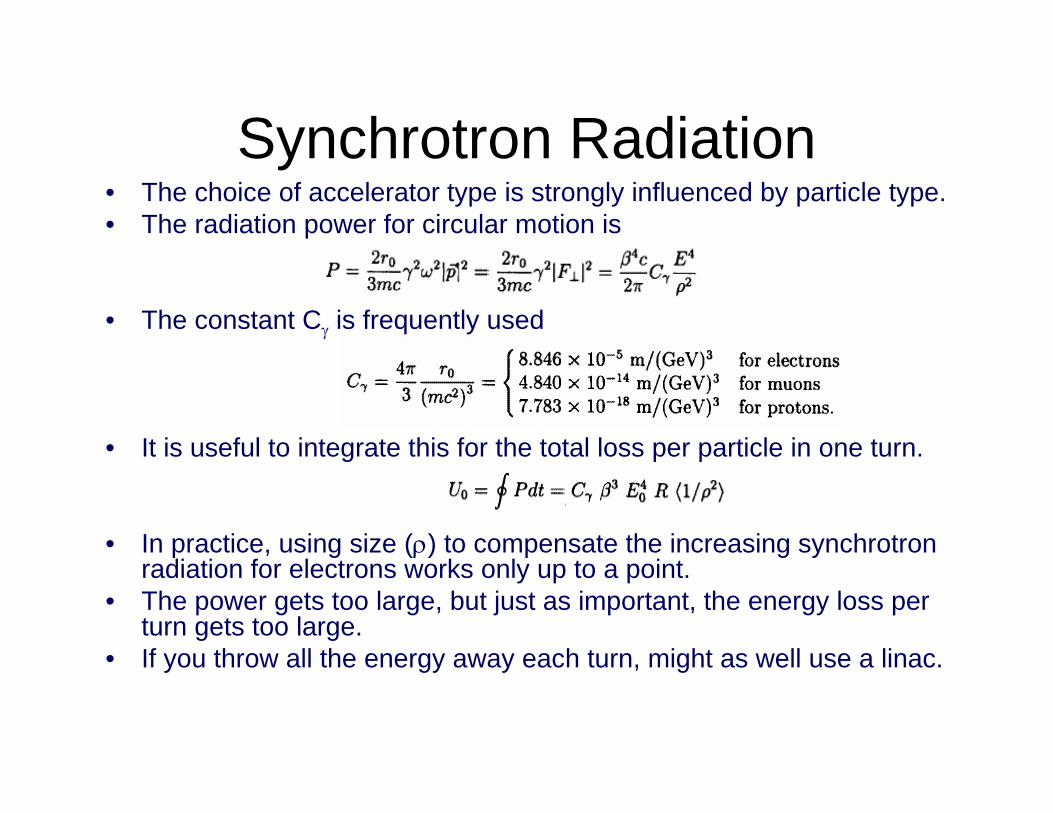
Synchrotron Radiation• The choice of accelerator type is strongly influenced by particle type.• The radiation power for circular motion is
• The constant Cγ is frequently used
• It is useful to integrate this for the total loss per particle in one turn.
• In practice, using size (ρ) to compensate the increasing synchrotron radiation for electrons works only up to a point.
• The power gets too large, but just as important, the energy loss per turn gets too large.
• If you throw all the energy away each turn, might as well use a linac.
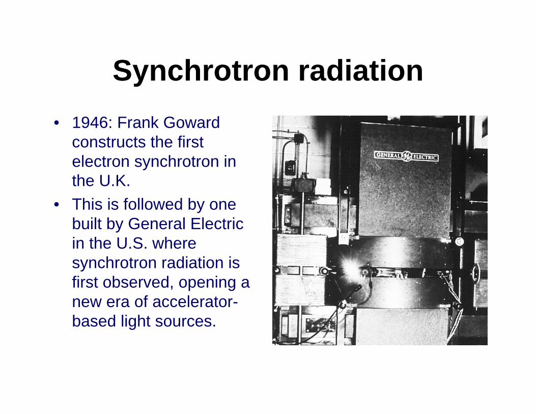
Synchrotron radiation• 1946: Frank Goward
constructs the first electron synchrotron in the U.K.
• This is followed by one built by General Electric in the U.S. where synchrotron radiation is first observed, opening a new era of accelerator-based light sources.
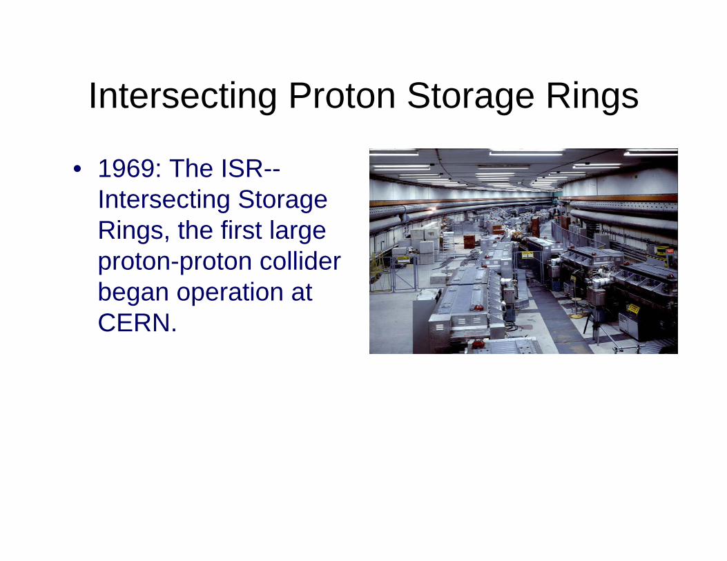
Intersecting Proton Storage Rings
• 1969: The ISR--Intersecting Storage Rings, the first large proton-proton collider began operation at CERN.
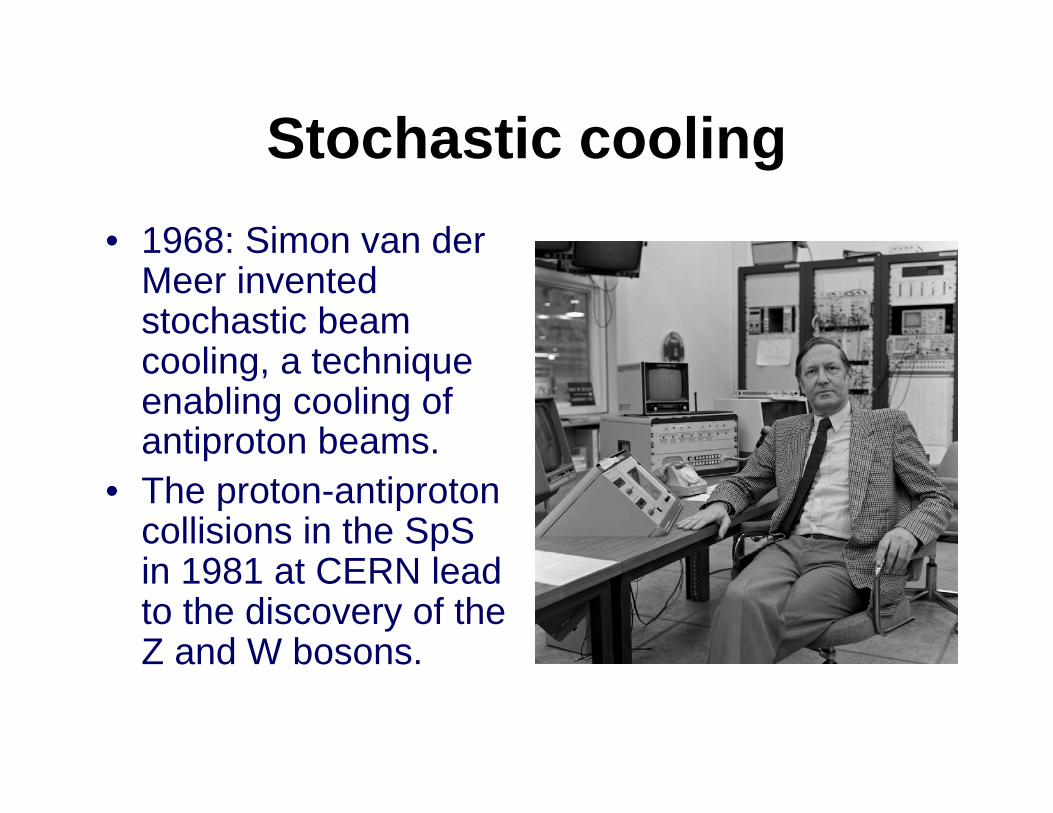
Stochastic cooling• 1968: Simon van der
Meer invented stochastic beam cooling, a technique enabling cooling of antiproton beams.
• The proton-antiproton collisions in the SpSin 1981 at CERN lead to the discovery of the Z and W bosons.
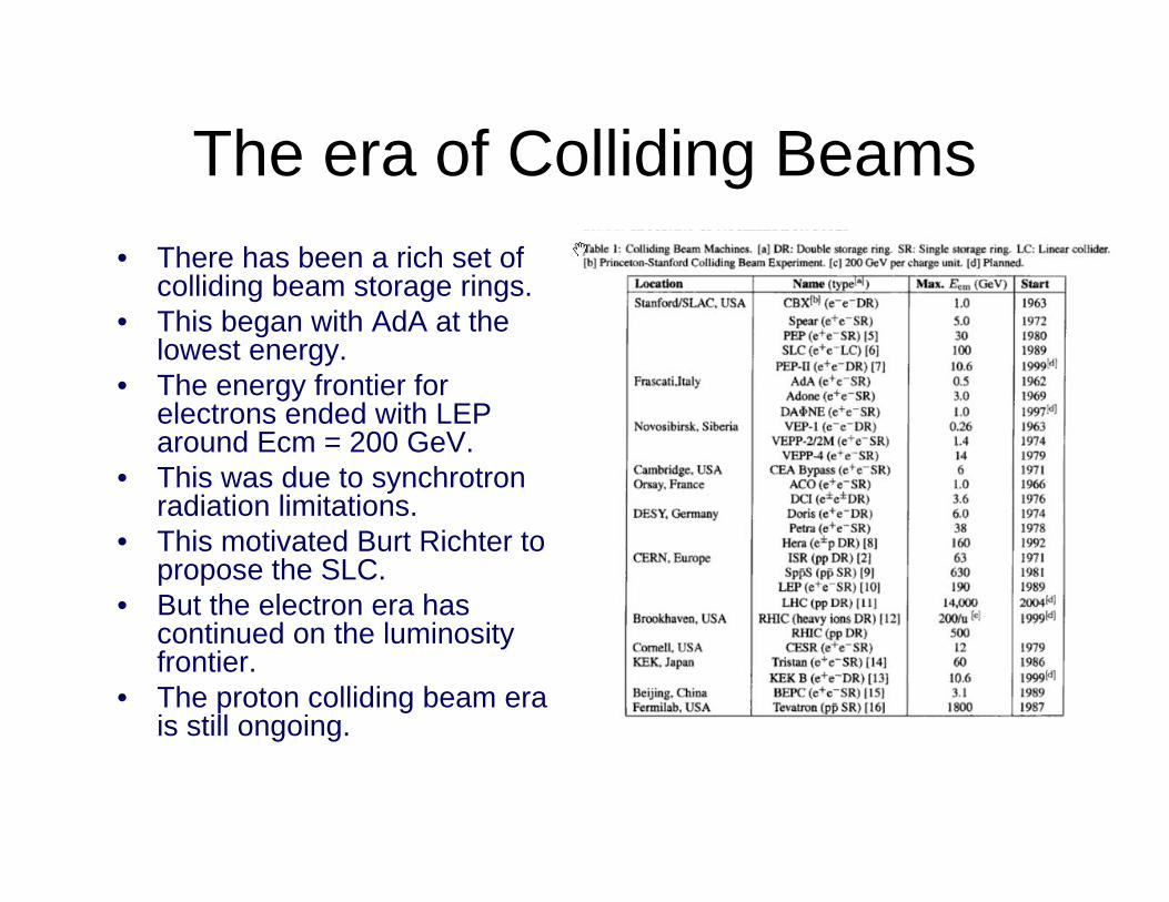
The era of Colliding Beams• There has been a rich set of
colliding beam storage rings.• This began with AdA at the
lowest energy.• The energy frontier for
electrons ended with LEP around Ecm = 200 GeV.
• This was due to synchrotron radiation limitations.
• This motivated Burt Richter to propose the SLC.
• But the electron era has continued on the luminosity frontier.
• The proton colliding beam era is still ongoing.
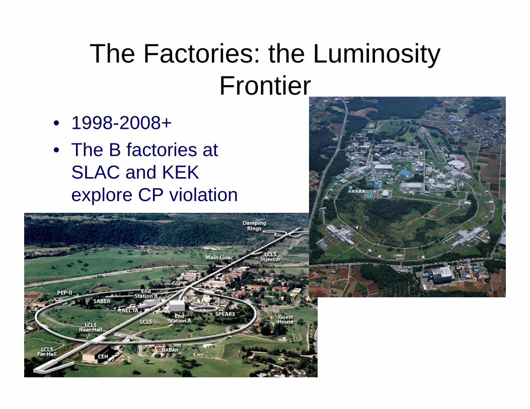
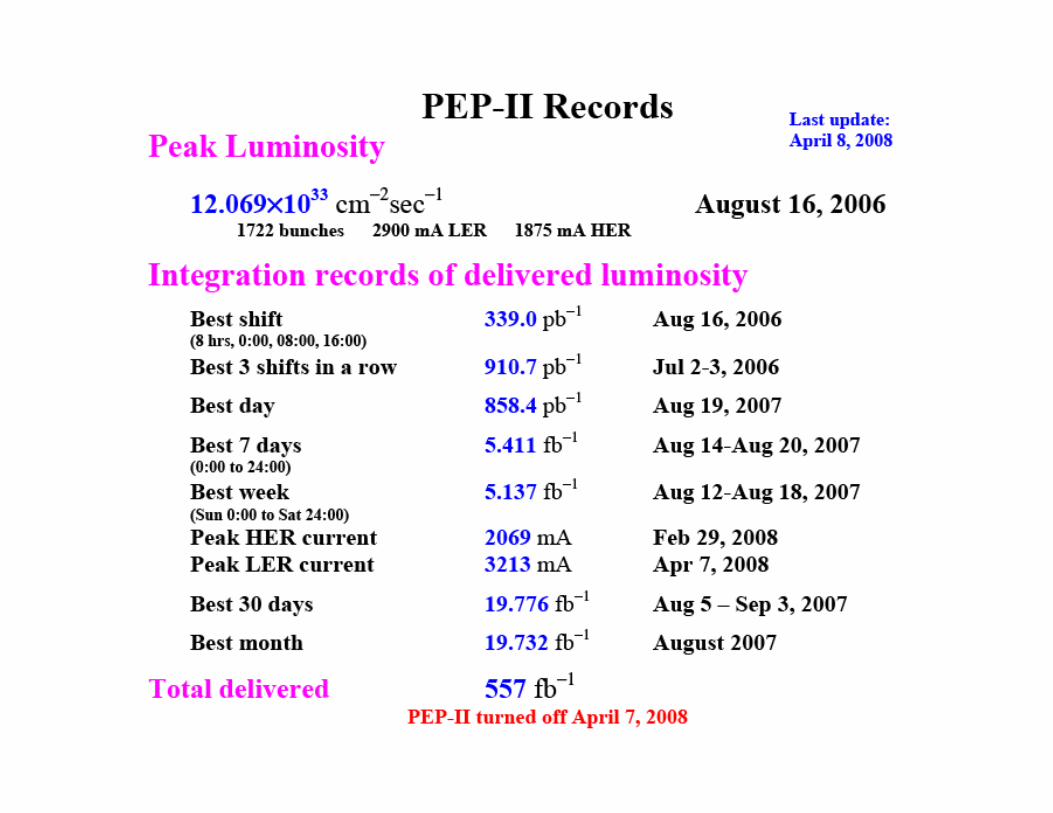
The Factories: the Luminosity Frontier
• 1998-2008+• The B factories at
SLAC and KEK explore CP violation
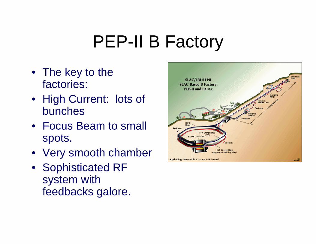
PEP-II B Factory• The key to the
factories:• High Current: lots of
bunches• Focus Beam to small
spots.• Very smooth chamber• Sophisticated RF
system with feedbacks galore.
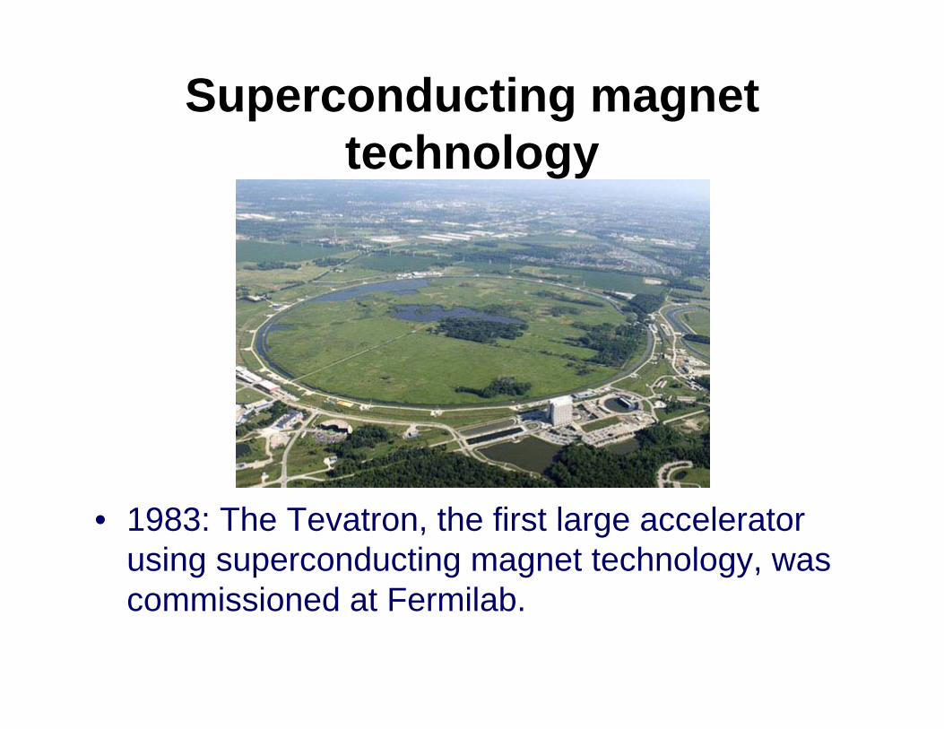
Superconducting magnet technology
• 1983: The Tevatron, the first large accelerator using superconducting magnet technology, was commissioned at Fermilab.
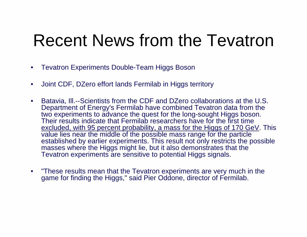
Recent News from the Tevatron• Tevatron Experiments Double-Team Higgs Boson
• Joint CDF, DZero effort lands Fermilab in Higgs territory
• Batavia, Ill.--Scientists from the CDF and DZero collaborations at the U.S. Department of Energy's Fermilab have combined Tevatron data from the two experiments to advance the quest for the long-sought Higgs boson. Their results indicate that Fermilab researchers have for the first time excluded, with 95 percent probability, a mass for the Higgs of 170 GeV. This value lies near the middle of the possible mass range for the particle established by earlier experiments. This result not only restricts the possible masses where the Higgs might lie, but it also demonstrates that the Tevatron experiments are sensitive to potential Higgs signals.
• "These results mean that the Tevatron experiments are very much in the game for finding the Higgs," said Pier Oddone, director of Fermilab.
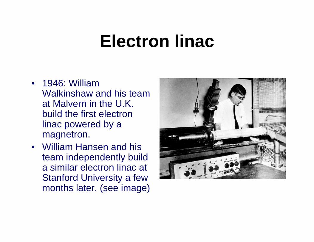
Electron linac
• 1946: William Walkinshaw and his team at Malvern in the U.K. build the first electron linac powered by a magnetron.
• William Hansen and his team independently build a similar electron linac at Stanford University a few months later. (see image)
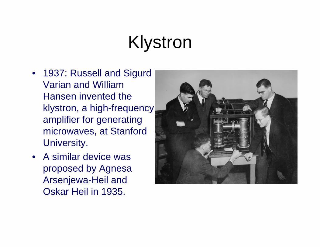
Klystron• 1937: Russell and Sigurd
Varian and William Hansen invented the klystron, a high-frequency amplifier for generating microwaves, at Stanford University.
• A similar device was proposed by AgnesaArsenjewa-Heil and Oskar Heil in 1935.
3–988334A1
P
pLoad(a)
(b)
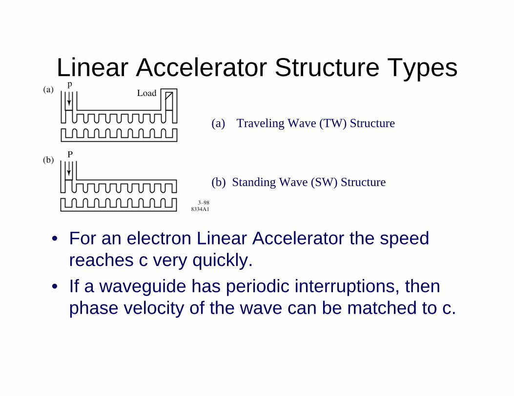
(a) Traveling Wave (TW) Structure
(b) Standing Wave (SW) Structure
Linear Accelerator Structure Types
• For an electron Linear Accelerator the speed reaches c very quickly.
• If a waveguide has periodic interruptions, then phase velocity of the wave can be matched to c.
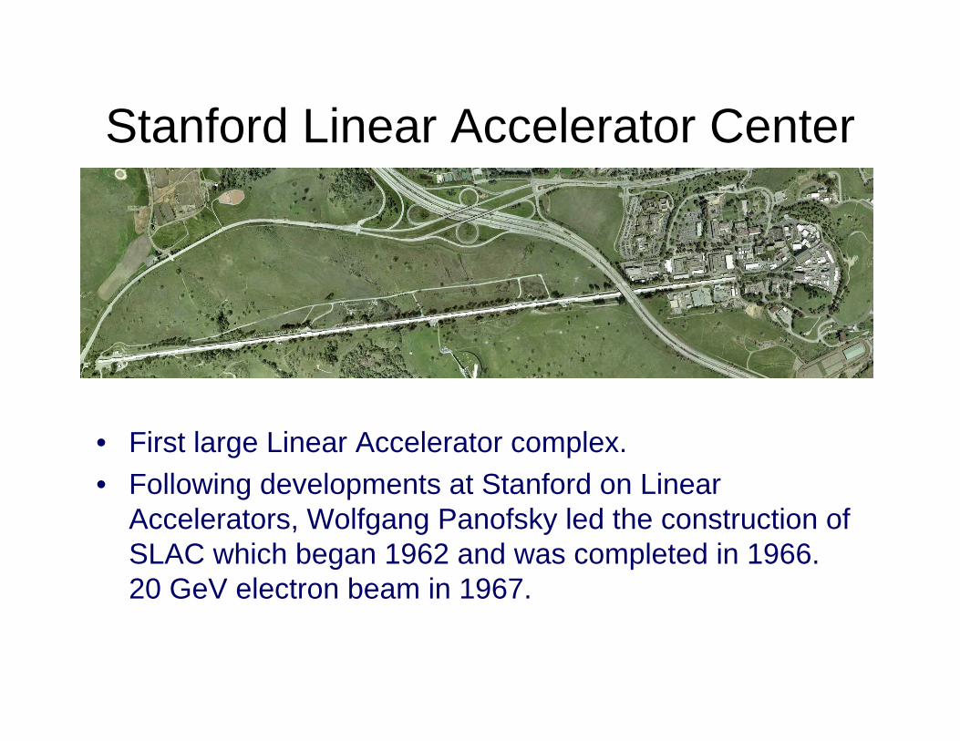
Stanford Linear Accelerator Center
• First large Linear Accelerator complex.• Following developments at Stanford on Linear
Accelerators, Wolfgang Panofsky led the construction of SLAC which began 1962 and was completed in 1966. 20 GeV electron beam in 1967.
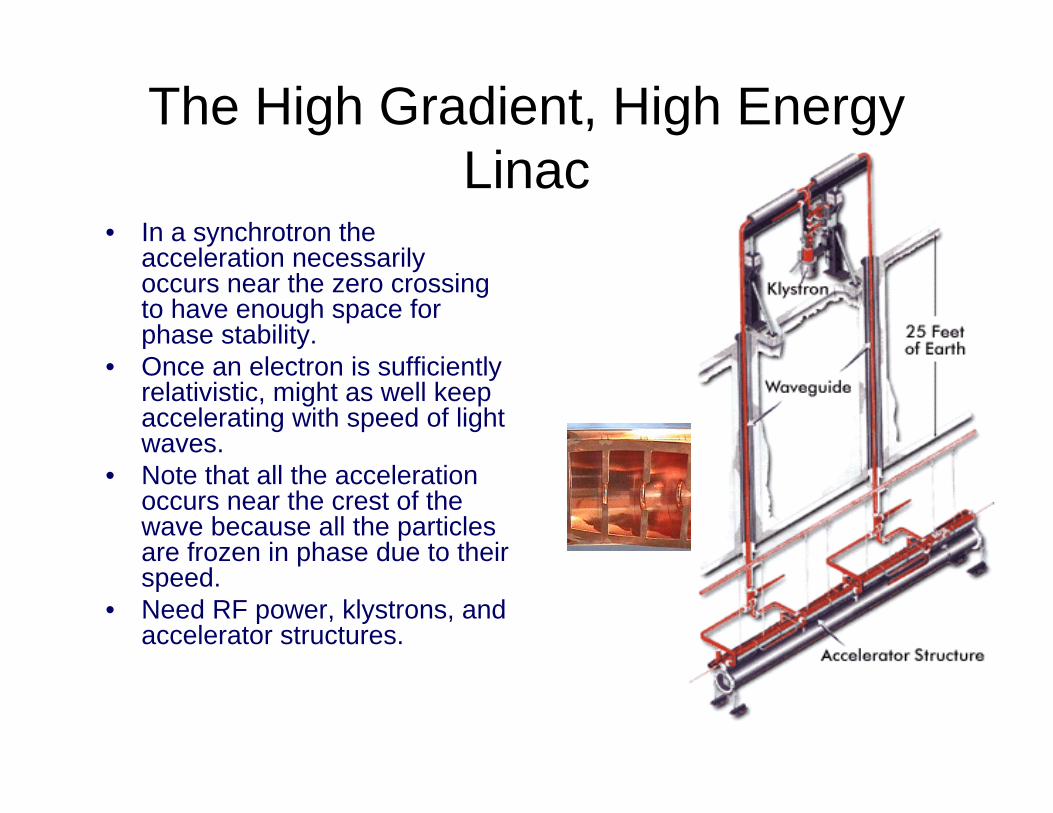
The High Gradient, High Energy Linac
• In a synchrotron the acceleration necessarily occurs near the zero crossing to have enough space for phase stability.
• Once an electron is sufficiently relativistic, might as well keep accelerating with speed of light waves.
• Note that all the acceleration occurs near the crest of the wave because all the particles are frozen in phase due to their speed.
• Need RF power, klystrons, and accelerator structures.
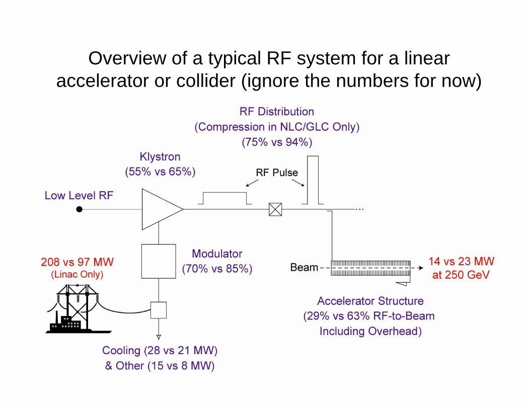
Overview of a typical RF system for a linear accelerator or collider (ignore the numbers for now)
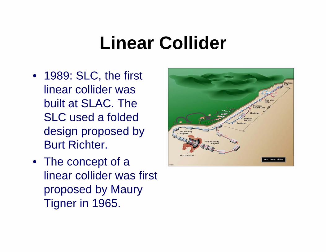
Linear Collider• 1989: SLC, the first
linear collider was built at SLAC. The SLC used a folded design proposed by Burt Richter.
• The concept of a linear collider was first proposed by Maury Tigner in 1965.
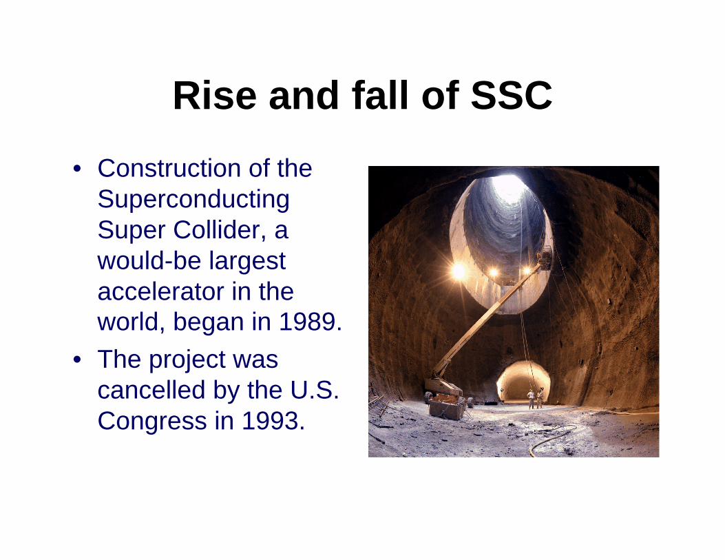
Rise and fall of SSC• Construction of the
Superconducting Super Collider, a would-be largest accelerator in the world, began in 1989.
• The project was cancelled by the U.S. Congress in 1993.
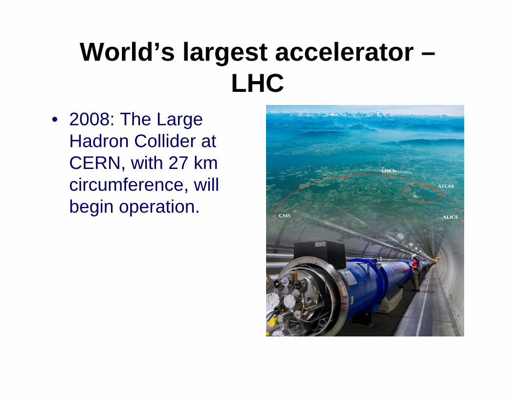
World’s largest accelerator –LHC
• 2008: The Large Hadron Collider at CERN, with 27 km circumference, will begin operation.
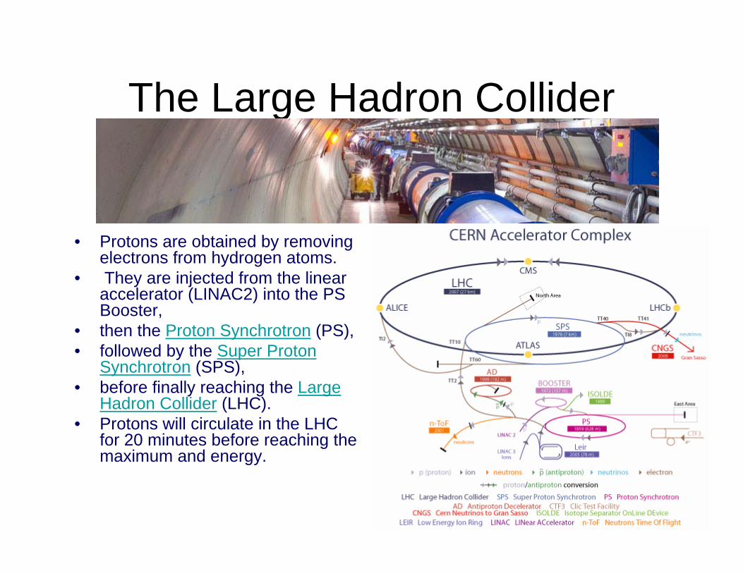
The Large Hadron Collider
• Protons are obtained by removing electrons from hydrogen atoms.
• They are injected from the linear accelerator (LINAC2) into the PS Booster,
• then the Proton Synchrotron (PS),• followed by the Super Proton
Synchrotron (SPS), • before finally reaching the Large
Hadron Collider (LHC). • Protons will circulate in the LHC
for 20 minutes before reaching the maximum and energy.
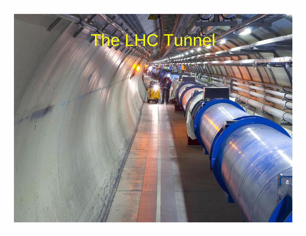
The LHC Tunnel
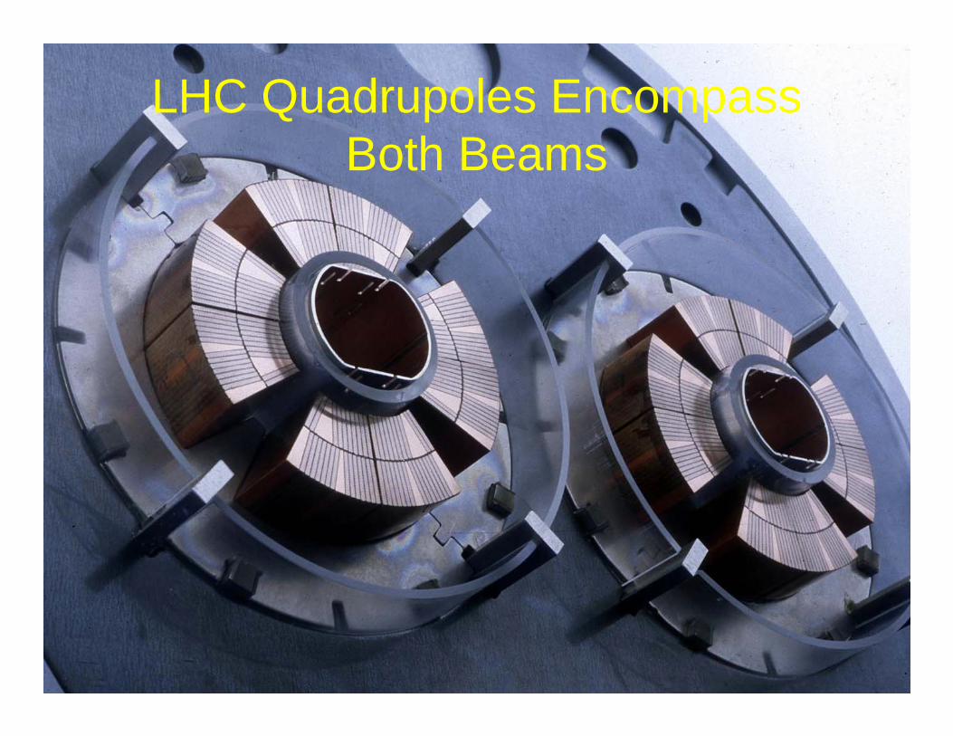
LHC Quadrupoles Encompass Both Beams
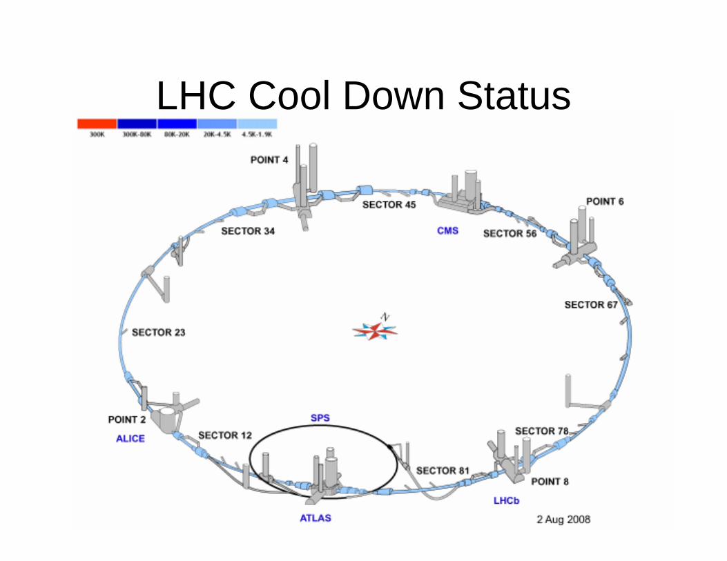
LHC Cool Down Status
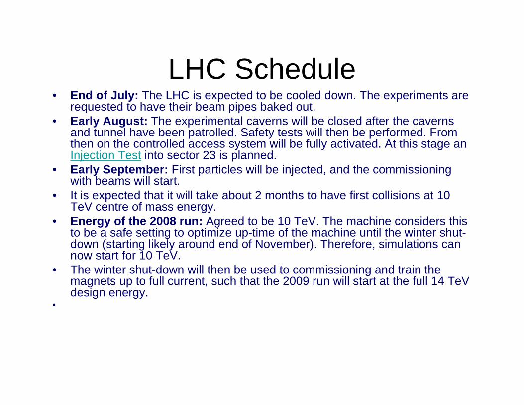
LHC Schedule• End of July: The LHC is expected to be cooled down. The experiments are
requested to have their beam pipes baked out. • Early August: The experimental caverns will be closed after the caverns
and tunnel have been patrolled. Safety tests will then be performed. From then on the controlled access system will be fully activated. At this stage an Injection Test into sector 23 is planned.
• Early September: First particles will be injected, and the commissioning with beams will start.
• It is expected that it will take about 2 months to have first collisions at 10 TeV centre of mass energy.
• Energy of the 2008 run: Agreed to be 10 TeV. The machine considers this to be a safe setting to optimize up-time of the machine until the winter shut-down (starting likely around end of November). Therefore, simulations can now start for 10 TeV.
• The winter shut-down will then be used to commissioning and train the magnets up to full current, such that the 2009 run will start at the full 14 TeV design energy.
•
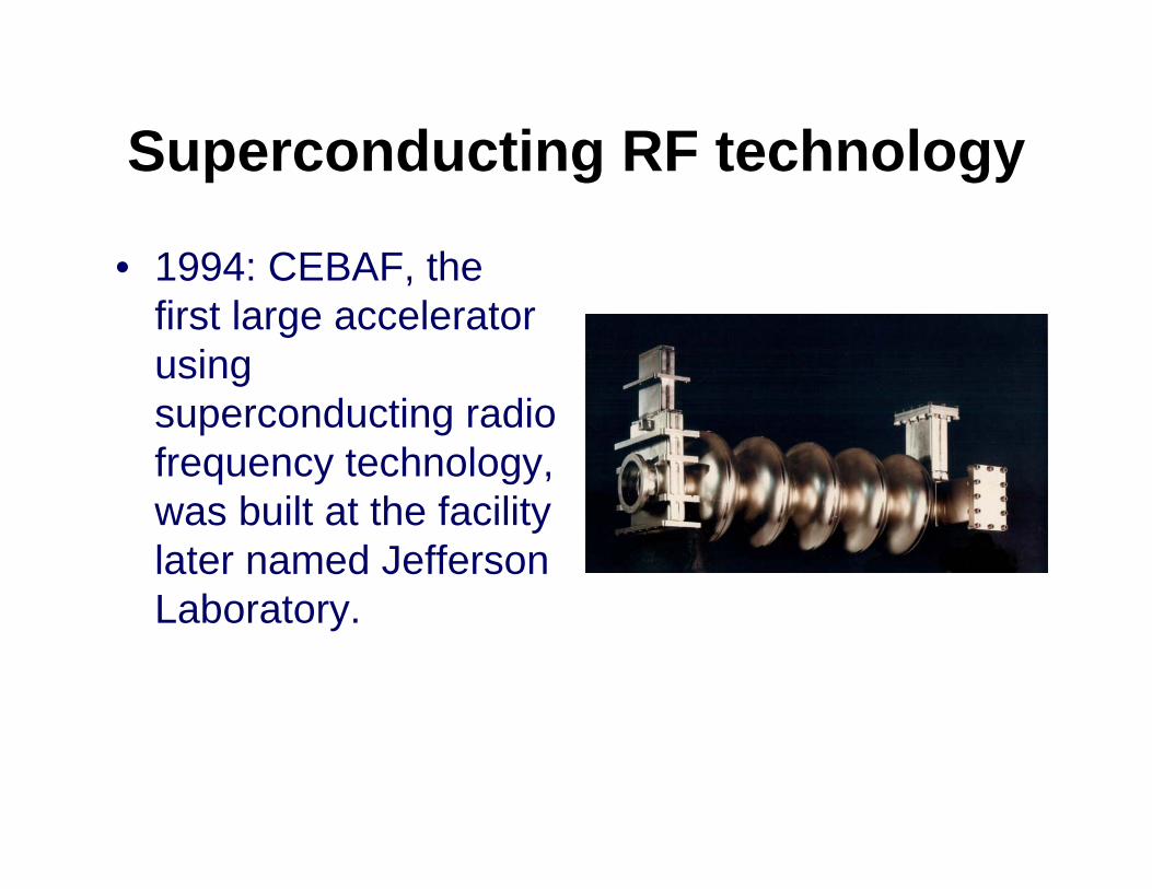
Superconducting RF technology
• 1994: CEBAF, the first large accelerator using superconducting radio frequency technology, was built at the facility later named Jefferson Laboratory.
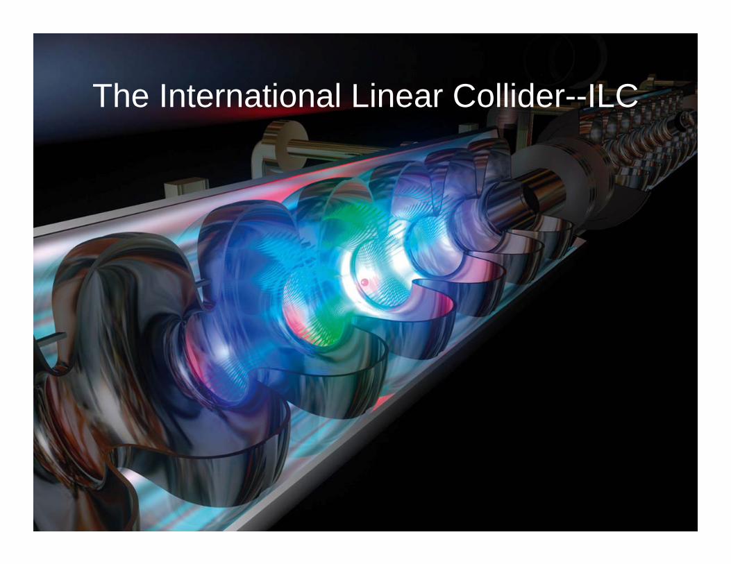
The International Linear Collider--ILC
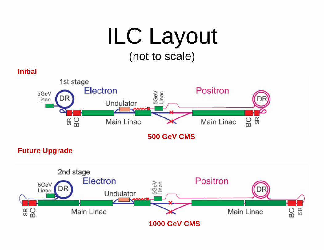
ILC Layout(not to scale)
1000 GeV CMS
Initial
Future Upgrade
500 GeV CMS
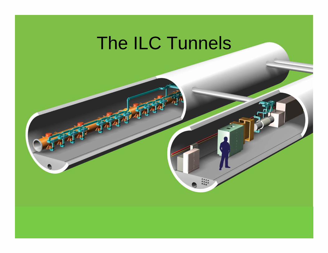
The ILC Tunnels
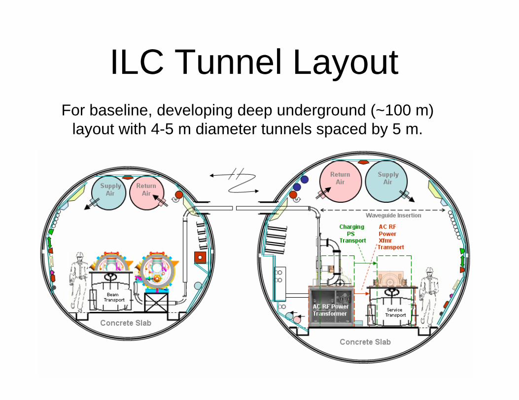
For baseline, developing deep underground (~100 m) layout with 4-5 m diameter tunnels spaced by 5 m.
ILC Tunnel Layout
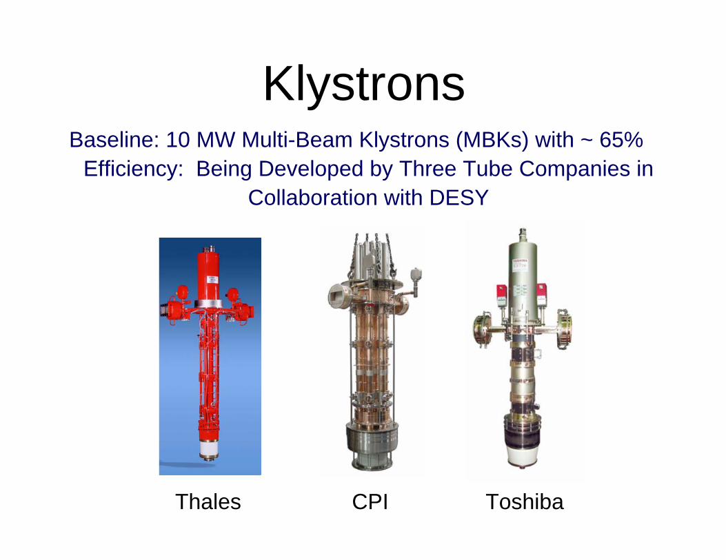
KlystronsBaseline: 10 MW Multi-Beam Klystrons (MBKs) with ~ 65%
Efficiency: Being Developed by Three Tube Companies in Collaboration with DESY
Thales CPI Toshiba
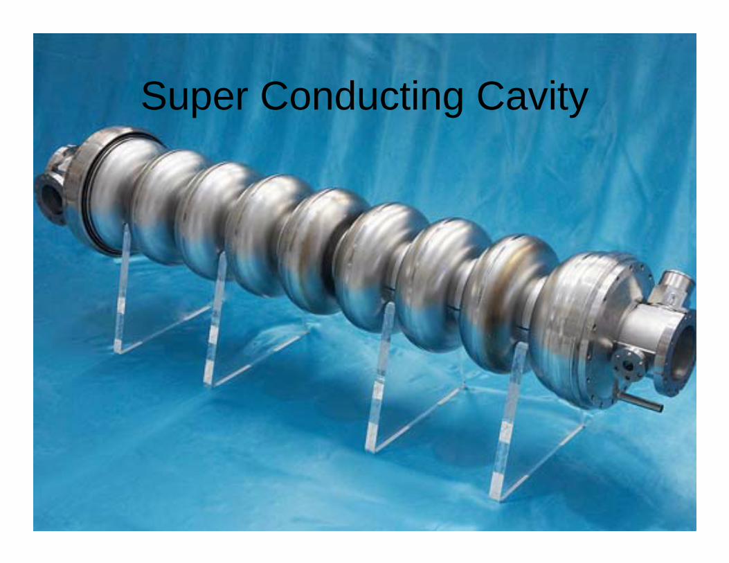
Super Conducting Cavity
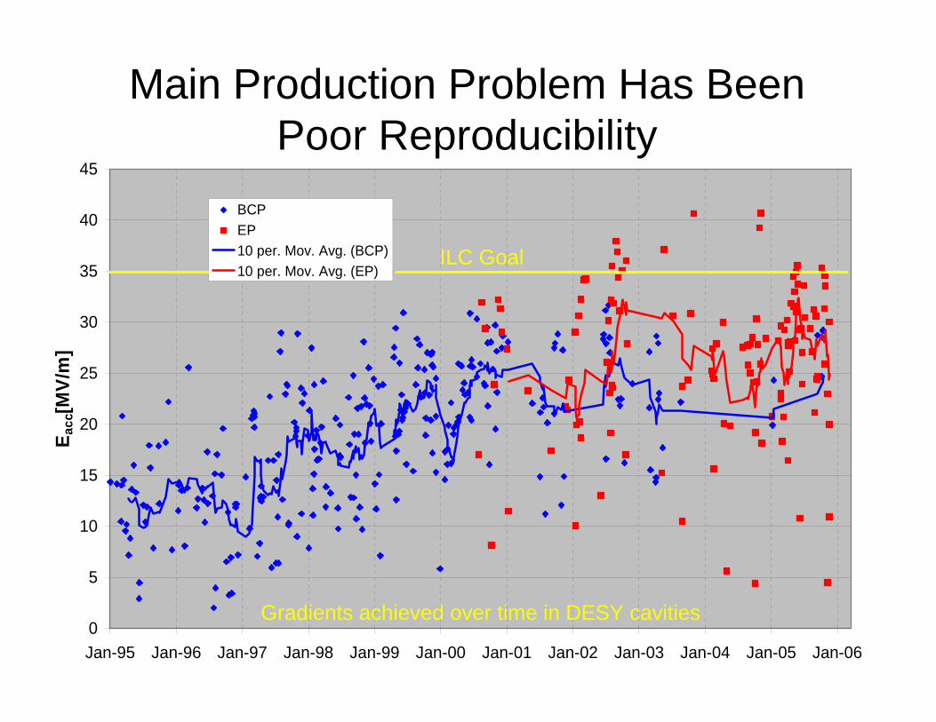
Main Production Problem Has Been Poor Reproducibility
0
5
10
15
20
25
30
35
40
45
Jan-95 Jan-96 Jan-97 Jan-98 Jan-99 Jan-00 Jan-01 Jan-02 Jan-03 Jan-04 Jan-05 Jan-06
E acc
[MV/
m]
BCPEP10 per. Mov. Avg. (BCP)10 per. Mov. Avg. (EP)
Gradients achieved over time in DESY cavities
ILC Goal
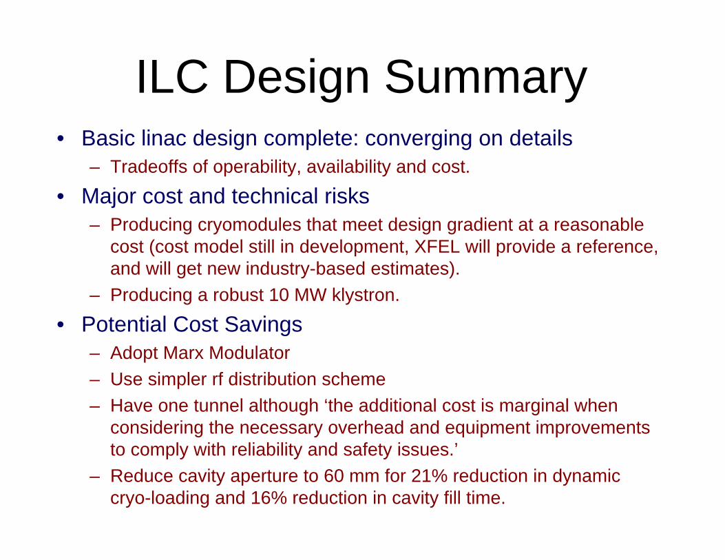
ILC Design Summary• Basic linac design complete: converging on details
– Tradeoffs of operability, availability and cost.
• Major cost and technical risks– Producing cryomodules that meet design gradient at a reasonable
cost (cost model still in development, XFEL will provide a reference, and will get new industry-based estimates).
– Producing a robust 10 MW klystron.
• Potential Cost Savings– Adopt Marx Modulator– Use simpler rf distribution scheme– Have one tunnel although ‘the additional cost is marginal when
considering the necessary overhead and equipment improvements to comply with reliability and safety issues.’
– Reduce cavity aperture to 60 mm for 21% reduction in dynamic cryo-loading and 16% reduction in cavity fill time.
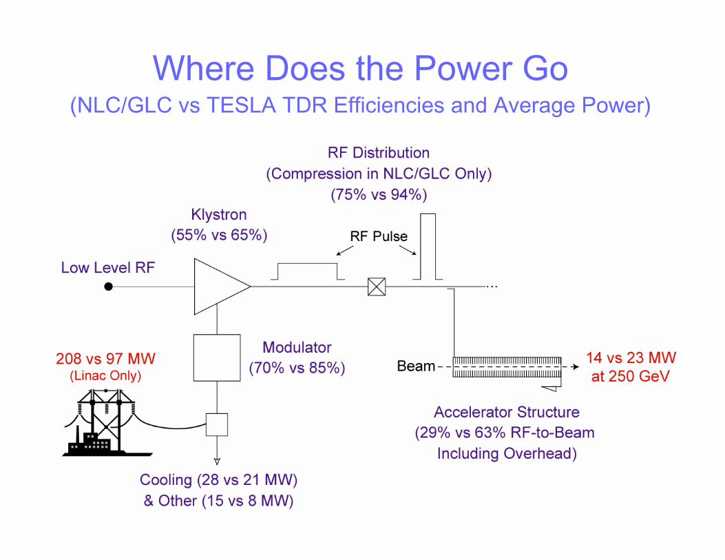
Where Does the Power Go(NLC/GLC vs TESLA TDR Efficiencies and Average Power)
High Gradient Acceleration
• The state of the art is at 11.4 GHz.• This is the frequency of the NLC design.• SLAC has more than 15 years experience
with this frequency.• CLIC has adopted 12 GHz for their two
beam collider.• What is the achievable gradient?• Tests show that 100 MV/m appears to be
achievable with very low breakdown rate.
1 0 - 6
1 0 - 5
0 . 0 0 0 1
0 . 0 0 1
0 . 0 1
0 . 1
1 0 0 1 2 0 1 4 0 1 6 0 1 8 0 2 0 0
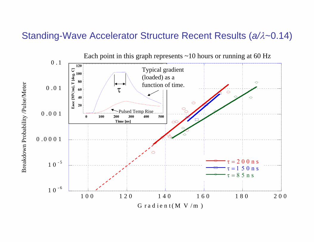
τ = 2 0 0 n sτ = 1 5 0 n sτ = 8 5 n s
Bre
akdo
wn
Prob
abili
ty /P
ulse
/Met
er
G r a d i e n t ( M V / m )
Standing-Wave Accelerator Structure Recent Results (a/λ~0.14)
τ
Typical gradient (loaded) as a function of time.
Pulsed Temp Rise
Each point in this graph represents ~10 hours or running at 60 Hz
100 150 20010
-7
10-6
10-5
10-4
RF Flat Top Pulse Width: ns
BK
D R
ate:
1/p
ulse
/m
95 100 105 110 11510-7
10-6
10-5
10-4
Unloaded Gradient: MV/m
BK
D R
ate:
1/p
ulse
/m
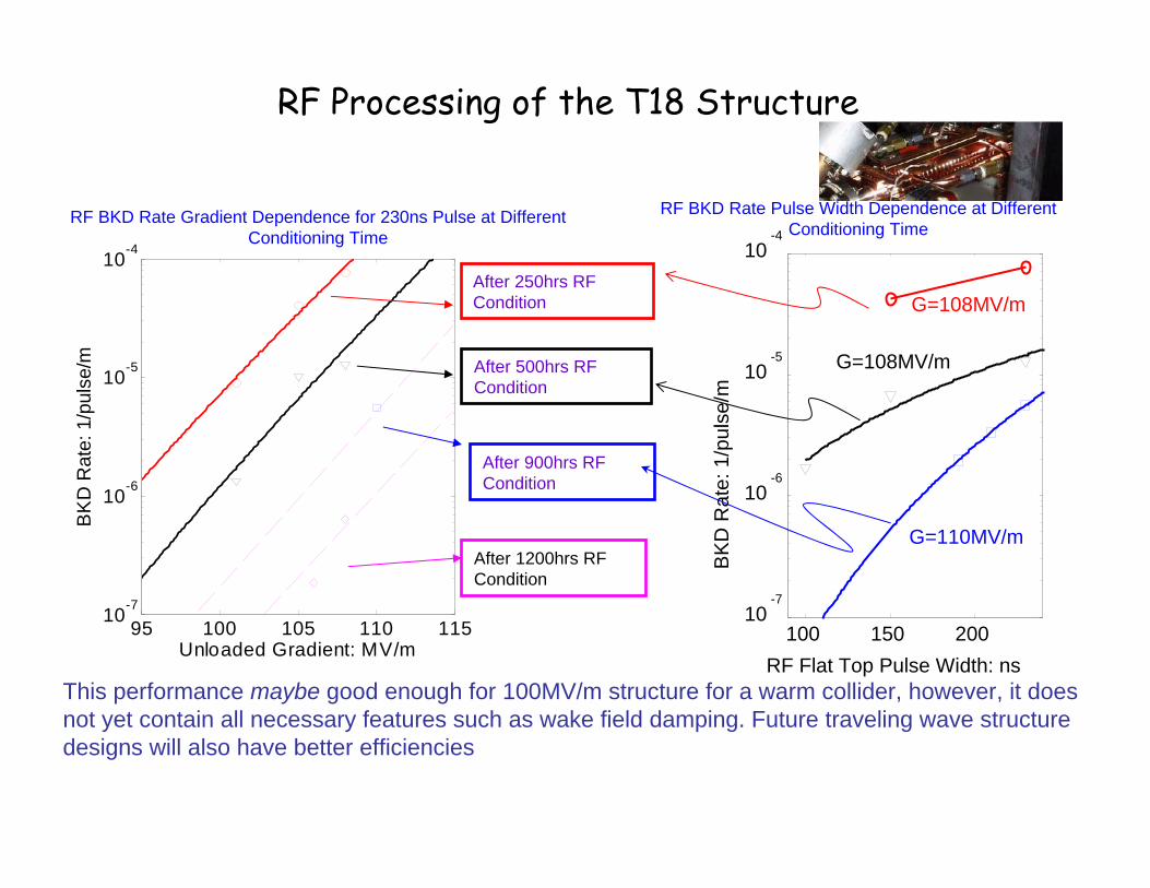
RF BKD Rate Gradient Dependence for 230ns Pulse at Different Conditioning Time
After 250hrs RF Condition
After 500hrs RF Condition
After 900hrs RF Condition
RF BKD Rate Pulse Width Dependence at Different Conditioning Time
G=108MV/m
G=108MV/m
G=110MV/m
RF Processing of the T18 Structure
After 1200hrs RF Condition
This performance maybe good enough for 100MV/m structure for a warm collider, however, it does not yet contain all necessary features such as wake field damping. Future traveling wave structure designs will also have better efficiencies
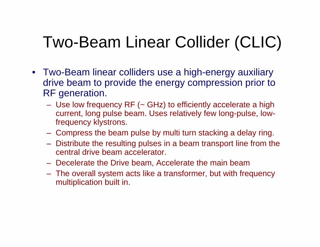
Two-Beam Linear Collider (CLIC)
• Two-Beam linear colliders use a high-energy auxiliary drive beam to provide the energy compression prior to RF generation.– Use low frequency RF (~ GHz) to efficiently accelerate a high
current, long pulse beam. Uses relatively few long-pulse, low-frequency klystrons.
– Compress the beam pulse by multi turn stacking a delay ring.– Distribute the resulting pulses in a beam transport line from the
central drive beam accelerator.– Decelerate the Drive beam, Accelerate the main beam– The overall system acts like a transformer, but with frequency
multiplication built in.
Accelerator Structure Accelerator StructureAccelerator StructureAccelerator Structure
F Quad BPM
760 MW 760 MW
D Quad BPM
B P M
Q u a d
MAIN LINAC
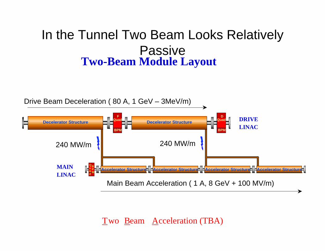
Two-Beam Module Layout
Two Beam Acceleration (TBA)
Drive Beam Deceleration (190 A, 1.3 GeV - 1.5 MV/m)
Main Beam Acceleration (0.8 A, 8 GeV + 93 MV/m)
DRIVE LINAC
Decelerator Structure Decelerator Structure
In the Tunnel Two Beam Looks Relatively Passive
Drive Beam Deceleration ( 80 A, 1 GeV – 3MeV/m)
Main Beam Acceleration ( 1 A, 8 GeV + 100 MV/m)
240 MW/m 240 MW/m
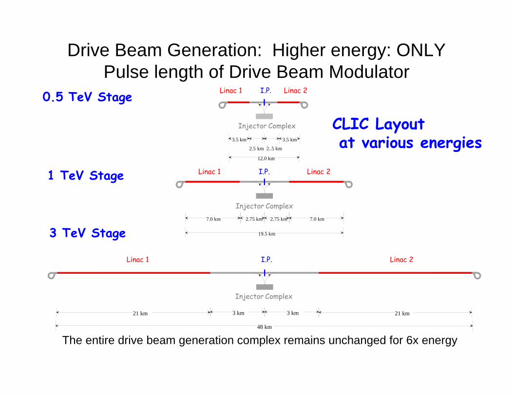
CLIC Layoutat various energies
3 TeV Stage
Linac 1 Linac 2
Injector Complex
I.P.
3 km21 km 21 km3 km
48 km
Linac 1 Linac 2
Injector Complex
I.P.
2.75 km2.75 km7.0 km 7.0 km
19.5 km
1 TeV Stage
0.5 TeV Stage Linac 1 Linac 2
Injector Complex
I.P.
3.5 km
2.5 km 2..5 km
3.5 km
12.0 km
Drive Beam Generation: Higher energy: ONLY Pulse length of Drive Beam Modulator
The entire drive beam generation complex remains unchanged for 6x energy
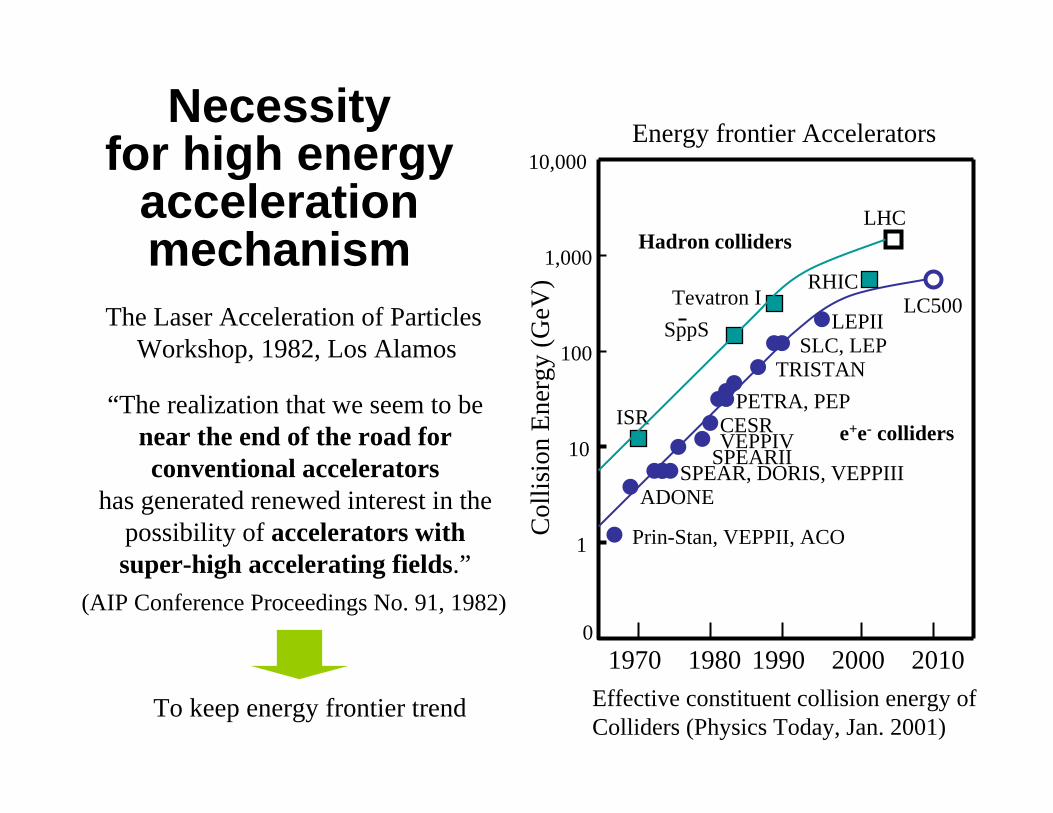
Necessity for high energy
acceleration mechanism
Effective constituent collision energy ofColliders (Physics Today, Jan. 2001)
1970 1980 1990 2000 20100
1
10
100
1,000
10,000
Col
lisio
n En
ergy
(GeV
)Prin-Stan, VEPPII, ACO
ADONESPEAR, DORIS, VEPPIII
SPEARIIVEPPIVCESR
PETRA, PEPTRISTAN
SLC, LEPLEPII
LC500
ISR
SppSTevatron I
LHC
e+e- colliders
Hadron colliders
RHIC
Energy frontier Accelerators
“The realization that we seem to be near the end of the road forconventional accelerators
has generated renewed interest in thepossibility of accelerators withsuper-high accelerating fields.”
The Laser Acceleration of Particles Workshop, 1982, Los Alamos
(AIP Conference Proceedings No. 91, 1982)
To keep energy frontier trend
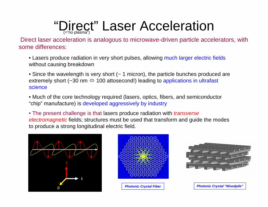
“Direct” Laser AccelerationDirect laser acceleration is analogous to microwave-driven particle accelerators, with some differences:
E
k
B Photonic Crystal Fiber Photonic Crystal “Woodpile”
(=“no plasma”)
• Lasers produce radiation in very short pulses, allowing much larger electric fieldswithout causing breakdown
• Since the wavelength is very short (~ 1 micron), the particle bunches produced are extremely short (~30 nm 100 attosecond!) leading to applications in ultrafast science
• Much of the core technology required (lasers, optics, fibers, and semiconductor “chip” manufacture) is developed aggressively by industry
• The present challenge is that lasers produce radiation with transverse electromagnetic fields; structures must be used that transform and guide the modes to produce a strong longitudinal electric field.
4 5 6 7 8 9 10 11 120
5
10
15
20
25
30
35
40
Undulator Gap (mm)
IFEL
Mod
ulat
ion
(keV
; FW
HM
)
IFEL Gap Scan Data
Simulation x 0.67Data
4th
5th 6th
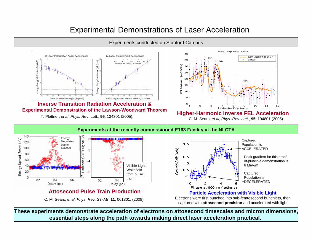
Inverse Transition Radiation Acceleration &Experimental Demonstration of the Lawson-Woodward Theorem Higher-Harmonic Inverse FEL Acceleration
C. M. Sears, et al, Phys. Rev. Lett., 95, 194801 (2005).T. Plettner, et al, Phys. Rev. Lett., 95, 134801 (2005).
Attosecond Pulse Train ProductionC. M. Sears, et al, Phys. Rev. ST-AB, 11, 061301, (2008).
Particle Acceleration with Visible LightElectrons were first bunched into sub-femtosecond bunchlets, then
captured with attosecond precision and accelerated with light
Visible Light Wakefield from pulse train
Energy Modulation due to buncher
Experimental Demonstrations of Laser Acceleration
Experiments at the recently commissioned E163 Facility at the NLCTA
Experiments conducted on Stanford Campus
These experiments demonstrate acceleration of electrons on attosecond timescales and micron dimensions,essential steps along the path towards making direct laser acceleration practical.
Captured Population is ACCELERATED
Captured Population is DECELERATED
Peak gradient for this proof-of-principle demonstration is 6 MeV/m
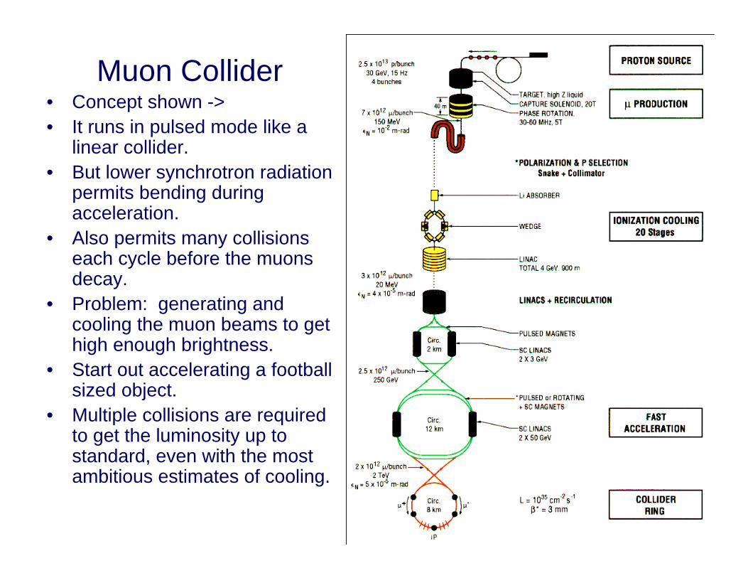
Muon Collider• Concept shown ->• It runs in pulsed mode like a
linear collider.• But lower synchrotron radiation
permits bending during acceleration.
• Also permits many collisions each cycle before the muonsdecay.
• Problem: generating and cooling the muon beams to get high enough brightness.
• Start out accelerating a football sized object.
• Multiple collisions are required to get the luminosity up to standard, even with the most ambitious estimates of cooling.
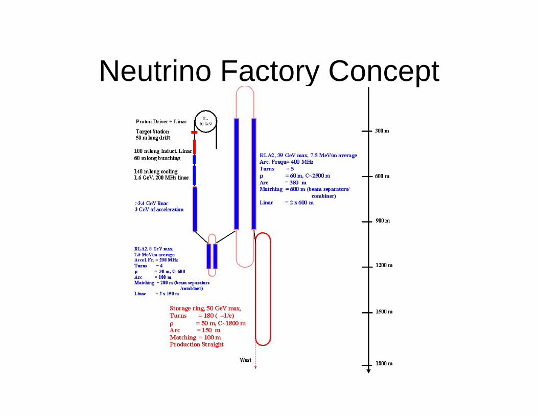
Neutrino Factory Concept
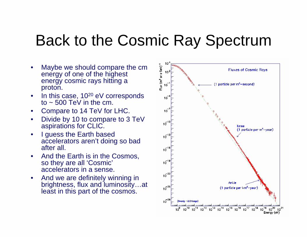
Back to the Cosmic Ray Spectrum• Maybe we should compare the cm
energy of one of the highest energy cosmic rays hitting a proton.
• In this case, 1020 eV corresponds to ~ 500 TeV in the cm.
• Compare to 14 TeV for LHC.• Divide by 10 to compare to 3 TeV
aspirations for CLIC.• I guess the Earth based
accelerators aren’t doing so bad after all.
• And the Earth is in the Cosmos, so they are all ‘Cosmic’accelerators in a sense.
• And we are definitely winning in brightness, flux and luminosity…at least in this part of the cosmos.
Acknowledgements
• History: Alex Chao and Handbook• Plasma Acceleration: Mark Hogan• High Gradient Acceleration: Sami Tantawi• Laser Acceleration: Eric Colby• ILC info: Chris Adolphsen
Reference to references