Embed Size (px)
Citation preview

1SSMTT-27M4
MAN-22060-US006 Rev D00
ISDN Option for theE1 Module
Part of the MTT and xDSLFamily of Products
User’s ManualSSMTT-27M4
302 Enzo Drive San Jose, CA 95138Tel: 1-408-363-8000 Fax: 1-408-363-8313

2 ISDN for the E1 Module
WARNINGUsing the supplied equipment in a manner not specified by Sunrise Telecom may impair the protection provided by the equipment.
CAUTIONS• Donotremoveorinsertthemodulewhilethetestsetison.Insertingorre-
movingamodulewiththepoweronmaydamagethemodule.• Donotremoveorinsertthesoftwarecartridgewhilethetestsetison.Oth-
erwise,damagecouldoccurtothecartridge.
End of Life Recycling and Disposal InformationDO NOT dispose of Waste Electrical and Electronic Equipment (WEEE) as unsorted municipal waste. For proper disposal return the product to SunriseTelecom. Please contact our local offices or service centers for information on howtoarrangethereturnandrecyclingofanyofourproducts.
EC Directive on Waste Electrical and Electronic Equipment (WEEE) The Waste Electrical and Electronic Equipment Directive aims to minimize the impact of the disposal of electrical and electronic equipment on the environment. It encourages and sets criteria for the collection, treatment, recycling, recovery, and disposal of waste electrical and electronic equipment.
©2010 Sunrise Telecom Incorporated. All rights reserved.Disclaimer:Contentssubjecttochangewithoutnotice.
3SSMTT-27M4
ISDN Option for the E1 Module
1 ISDN Menu ......................................................... 51.1 Test Configuration .............................................................6
1.2 Call Control .....................................................................11
1.3 Protocol Analysis ............................................................141.3.1 Filter .............................................................................141.3.2 Live Tracer ...................................................................211.3.3 Stored Messages .........................................................231.3.3.1 Temporary Buffer ......................................................231.3.3.2 Stored Traces ............................................................29
1.4 BERT and Results ..........................................................32
1.5 Automatic Test ................................................................351.5.1 Auto Scan ....................................................................351.5.2 Supplementary Services Scan ....................................371.5.3 Sequential Call ............................................................391.5.4 Bulk Call ......................................................................41
2 Applications .................................................... 452.1 Placing a Speech Call (ETSI) in TE Mode ......................45
2.2 Placing a Data Call and Running a BERT ......................46
2.3 Placing a Second Call ....................................................47
2.4 Receiving a Call ..............................................................47
2.5 Running a Supplementary Services Scan ......................47
2.6 Running an Auto Service Scan .......................................48
2.7 Running a Sequential Call Test .......................................48
3 Reference ........................................................ 493.1ISDNTechnologyOverview ............................................493.1.1ISDNNetworkArchitecture ..........................................493.1.2 ISDN Messages and their Functions ...........................523.1.3 DASS2 Technology ......................................................543.1.3.1 DASS2 Layer 2 .........................................................543.1.3.2 DASS2 Frame Types.................................................553.1.4 DPNSS Technology .....................................................56
4 General Information ....................................... 574.1 Testing and Calibration Statement ..................................57
4.2 Offices ............................................................................57
4.3 Express Limited Warranty ...............................................59
Index ..................................................................... 61

4 ISDN for the E1 Module

5SSMTT-27M4
1 ISDN Menu
TheISDNmenuisshowninFigure1.
PROTOCOL ANALYSIS
STORED MESSAGES1.3.3
FILTER
1.3.1
LIVE TRACER1.3.2
AUTOMATIC TEST
BULK CALL1.5.4
SEQUENTIAL CALL1.5.3
SUPP SERVICES SCAN
1.5.2AUTO SCAN
1.5.1
PROTOCOLS
OTHER MEASUREMENT
MEASUREMENT RESULT
TEST PATTERN
TEST CONFIGURATION
VF CHANNEL ACCESS
OTHER FEATURES
SYSTEM PARAMETERS
VIEW/STORE/PRINT
PROFILES
For all items other than PROTOCOLS, see the appropriate section in the SSMTT-27 User’s Manual.
MODULEKey
E1 MAIN MENU
AUTOMATIC TEST1.5
ISDN
BERT AND RESULTS1.4
PROTOCOL ANALYSIS1.3
CALL CONTROL
1.2TEST CONFIGURATION
1.1
ISDN ANALYSIS
1
PROTOCOLS
For all items other than ISDN ANALYSIS, see the appropriate option User’s Manual.
STORED MESSAGES
STORED MESSAGES1.3.2.2
TEMPORARY BUFFER
1.3.2.1
ISDN Notes• A “Downloading ISDN program” message will be displayed after selecting
ISDN ANALYSIS.• The test set must be configured for PCM-31 framing, E1SINGL or
E1DUAL.• ISDN CONFIGURATION will override module configuration.• Voice and data calls can be placed and received, along with conducting
various tests.• The status of the line is shown by messages on the top line; an in service
message is shown if the link is up and in service, and a not ready message is shown if the link is not ready (not in service).
• Current transmitted (Tx1) and received (Rx1 or Rx2) messages are shown on screen, on the second line from the top between ‘<carrots>’.
• When ISDN is selected from the PROTOCOL menu, the test set automati-cally starts the Layer 2 handshake and activates the D-channel.
Figure 1 ISDN Menu
6 ISDN for the E1 Module
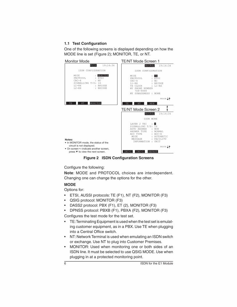
1.1 Test ConfigurationOneofthefollowingscreensisdisplayeddependingonhowtheMODE line is set (Figure 2); MONITOR, TE, or NT.
Filt 19:14:34
ISDN CONFIGURATION
MODE : MONITOR PROTOCOL : ETSI CRC-4 : NO SIGNALLING T/S: 16 L1-RX : BRIDGE L2-RX : BRIDGE
TE NT MONITOR
NotRdy 19:14:34
ISDN CONFIGURATION
MODE : TE PROTOCOL : ETSI CRC-4 : NO L1-RX : BRIDGE TX CLOCK : L1-RX MY PHONE NUMBER 708-9999 MY SUBADDRESS : NONE
more
TE NT MON
NotRdy 19:14:34
ISDN MORE
LAYER 2 TEI : 0 SIGNALLING T/S: 16 AUTO ANSWER : NON ANSWER TYPE : NORMAL AOC TYPE : AOC-E MODE : AUTOMATIC MESSAGE : FACILITY INFORMATION : UNIT
more
INC+1 INC-1 DEFAUT
Monitor Mode TE/NT Mode Screen 1
TE/NT Mode Screen 2
Notes:• In MONITOR mode, the status of the
circuit is not displayed.• On screen indicate another screen,
press to view the next screen.
Figure 2 ISDN Configuration Screens
Configurethefollowing:Note: MODE and PROTOCOL choices are interdependent. Changing one can change the options for the other.
MODEOptions for:• ETSI,AUSSIprotocols:TE(F1),NT(F2),MONITOR(F3)• QSIGprotocol:MONITOR(F3)• DASS2protocol:PBX(F1),ET(2),MONITOR(F3)• DPNSSprotocol:PBXB(F1),PBXA(F2),MONITOR(F3)Configures the test mode for the test set.• TE:TerminatingEquipmentisusedwhenthetestsetisemulat-
ingcustomerequipment,asinaPBX.UseTEwhenpluggingintoaCentralOfficeswitch.
• NT:NetworkTerminalisusedwhenemulatinganISDNswitchor exchange. Use NT to plug into Customer Premises.
• MONITOR:UsedwhenmonitoringoneorbothsidesofanISDNline.ItmustbeselectedtouseQSIGMODE.Usewhenplugging in at a protected monitoring point.

7SSMTT-27M4
• DASS2:Usebetweenthecustomer’sequipmentandanISDNlocalexchange.Therefore,thetwonon-monitorchoicesarePBX(F1)andET(F2):- PBX:Emulatecustomer’sequipmentandplugintoanISDN
exchange.- ET: Emulate an exchange to plug into customer equipment.
• DPNSS:ProvidessignallingbetweenPBXsconnected inaprivatedigitalnetwork.Thechoicesavailableare;PBXB(F1),PBXA(F2),andMONITOR(F3).
Notes:• WhenMONITORmodeisselected,theoptionspresentedwill
change;TxClockandtheoptionsfollowingwillnotbepresentexceptforSIGNALLINGT/S.
• When MONITOR mode is selected, CALL CONTROL andAUTOMATIC TEST are not available.
PROTOCOLOptions for:• MONITOR:ETSI(F1),AUSSI(F2),QSIG,(F3),DASS2(more,
F1), DPNSS (more, F2)• TE,NT:ETSI(F1),AUSSI(F2),DASS2(F3),DPNSS(F4)• PBX,ET:DASS2(F3)• PBXA,PBXB:DPNSS(F4)ChoosethetypeofISDNswitchtousefortesting.
• ETSI(ITU):EuropeanTelecommunicationStandardandITUQ.931standard.
• AUSSIE:Australiannationalstandard.• QSIG:Globalsignallingsystemforcorporatenetworking;the
signallinginformationofQSIGandtheuser’sinformation(voice,data, etc.) do not necessarily need to be transmitted over the same physical link.
• DASS2:DefinedbyBTNR190.• DPNSS:DefinedbyBTNR188.
CRC-4Options: YES (F1), NO (F2)
ThisallowsthetestsettomeasureCRC-4errorsontheincomingsignal and also transmit CRC-4 bits on the outgoing signal.
L1-RX and L2-RX(L2-RXinISDNmonitormodeonly)Options:TERM(F1),BRIDGE(F2),MONITOR(F3)
Specify the line interface mode for testing.
• TERM:UsedwhensendingandreceivinganE1signal.Itisthe most common mode used for out-of-service testing. The
8 ISDN for the E1 Module
testsetterminatesthereceivedsignalwithalowimpedancetermination, and requires that the circuit be disrupted for testing. A 75ΩterminationisusedforBNCand1.6/5.6mmconnec-tors. A 120Ω termination is used for BR2 and 3-pin banana connectors.
• BRIDGE:This issimilar toMonitormode.However, inBridgemode, the test set applies high impedance isolation resistors to the circuit under test. This protects the signal from disruptions. It is most commonly used for testing live circuits.
If connecting to the circuit through a MON jack to the test set whileinBridgemode,thiscanresultintwoisolationcircuitson the signal. This may cause the test set to report a loss of signal and be unable to perform measurements.
• MONITOR: Used for monitoring from a protected monitoringpoint.ThesignalisprovidedfromtheMONjackofanE1networkelement.Thenetworkelementhasisolatedthemonitorsignalfromthelivesignalwithhighimpedanceresistors.ThetestsethasanAGC(AutomaticGainControl)circuittocompensateforthe resistive loss of -15 dB to -30 dB. If the signal source is not aresistivelyattenuatedmonitoroutputsignal,theAGCwillnotoperateproperly,andasaresult,codeerrorand/orotherproblemindicatorswillbeshownonthetestset.
This mode is useful because it protects the live signal from possibledisruptionscausedbythetestingprocess.Itallowsobservingthelinewhilethecircuitisoperational.
TX CLOCKOptions:L1-RX(F1),INTERN(F2)
Determine the timing source for the transmitted signal.• L1-RX:UsethetimingsignalreceivedonLine1,ifplugging
intoaswitchwhichrequiresthetestsettobesynchronizedtothenetwork,orifinTEmode.
• INTERN:Usethetestset’sinternalclockasthetimingsourcetoemulateapieceofnetworkequipment(NT).
ThenexttwoitemsarenotpresentinMONITORmode.
MY PHONE NUMBEROptions: Any up to 22 digit number
Enter thenumberassociatedwith the line that isbeingdialedfrom by pressing EDIT (F1) and use the numeric keypad to enter the number. If a mistake is made, press <- (F2) to remove the highlighted digit, then reenter the number. When finished, press DONE (F1).

9SSMTT-27M4
MY SUBADDRESSOptions: Any up to five digit number.If appropriate, enter in the subaddress of the line that is originat-ing thecall, byusing theproceduredescribed inMYPHONENUMBER.
IneverymodeotherthanMONITOR,whenthesettinghavebeencompleted, press to configure the next screen. In MONITOR mode,SIGNALLINGT/Swillappearonthefirstscreen.
LAYER 2 TEIOptions: 0—63, DEFAULT (F3)The TEI (Terminal Endpoint Identifier) identifies the user device. CCITTQ.921hasdefinedthreegroupsofTEIvalues:• 0—63:FixedornonautomaticTEIassignmentuserequipment• 64—126:AutomaticTEIassignmentuserequipment• 127:GroupTEIforbroadcastdatalinkconnectionDefault is 0; to change press INC+1 (F1) or DEC-1 (F2).
SIGNALLING T/SOptions 1—31 for PCM-31Select the timeslot carrying the signalling; the D-channel. This is usually 16 or 15. To change it, press INC+1 (F1) or DEC-1 (F2).
AUTO ANSWEROptions: OFF (F1), ON (F2)Determinewhetherornotthetestsetwillautomaticallyanswerincoming calls.• ON:Thetestsetautomaticallyanswercalls.• OFF:Answerorrejectcallsmanually.
ANSWER TYPEOptions: NORMAL (F1), LOOP (F2)Determinehowthetestsetwillhandleanacceptedcall.• NORMAL:Anincomingcallisanswered,andthenterminated.• LOOP:Acallisansweredandthenlooped.
AOC TYPEOptions: NONE (F1), AOC-D (F2), AOC-E (F3)GenerateandmonitorAOC(AdviceofCharge)messages,inor-dertoverifyfunctionalityofthePBXandtheAOCsupplementaryservicesprovidedbythenetwork.Ifused,setupthefollowingtwosettings;MODEandMESSAGE.IfconfiguredforTE,setupAOCREQUEST.
• AOC-D:Messagesduringacall.• AOC-E:Messagesattheendofacall.

10 ISDN for the E1 Module
MODEOptions: MANUAL (F1), AUTO (F2)• MANUAL:Ifselected,thetestsetwillsendanAOCmessage
after you press whileintheCALLCONTROLscreen.SeeSection 1.2.
• AUTO:Ifselected,thetestsetwillautomaticallysendanAOCmessage every ten seconds.
MESSAGEOptions: INFO (F1), FACILIT (F2)Select the type of message to send.
• INFO:SendanAOCinformationinanINFOmessage.• FACILIT:SendanAOCinformationinanFACILITYmessage.
If FACILIT is selected, configure INFORMATION.
INFORMATIONOptions : UNIT (F1), CURRENC (F2)Selectthetypeofinformationthatwillbeviewed.
• UNIT:Viewchargingunitinformation.• CURRENC:Viewcurrencyinformation.
AOC REQUESTOptions : ON (F1), OFF (F2)IfONthetestsetwillsendanAOCrequesttotheISDNswitchtoenable the AOC service.
When finished, press ESC.
11SSMTT-27M4
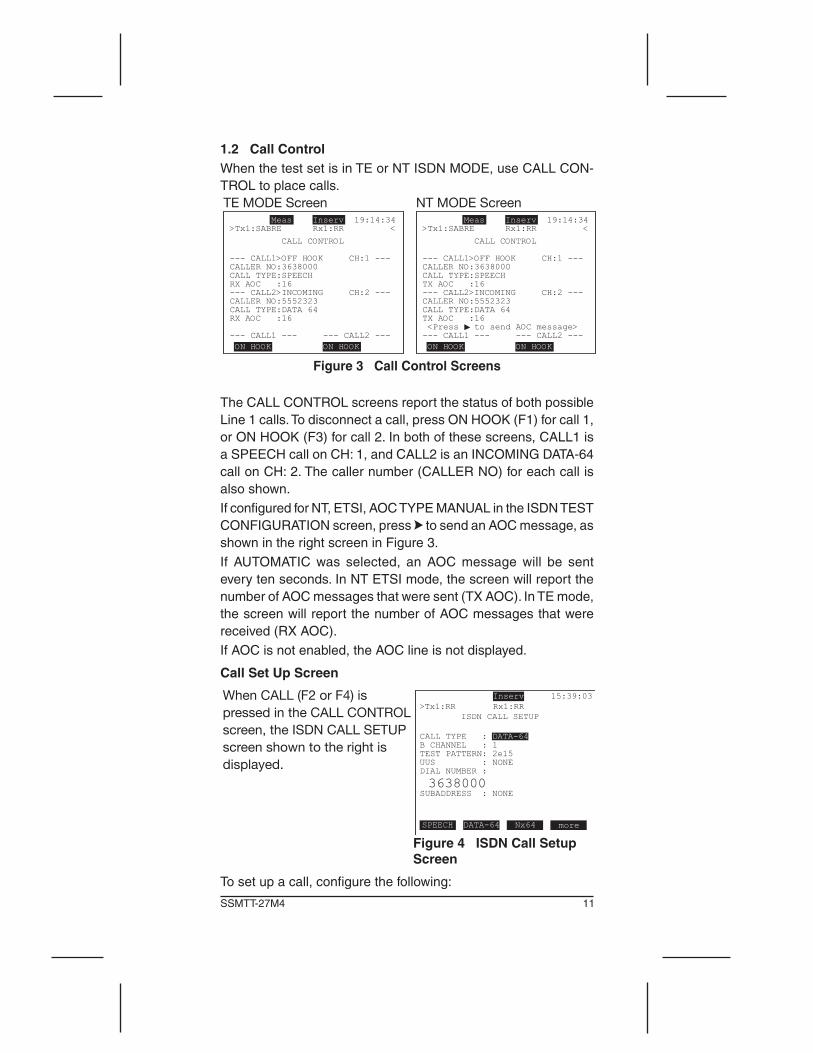
1.2 Call ControlWhen the test set is in TE or NT ISDN MODE, use CALL CON-TROL to place calls.
Meas Inserv 19:14:34>Tx1:SABRE Rx1:RR <
CALL CONTROL
--- CALL1>OFF HOOK CH:1 ---CALLER NO:3638000CALL TYPE:SPEECHTX AOC :16--- CALL2>INCOMING CH:2 ---CALLER NO:5552323CALL TYPE:DATA 64TX AOC :16 <Press to send AOC message> --- CALL1 --- --- CALL2 --- ON HOOK ON HOOK
NT MODE Screen Meas Inserv 19:14:34>Tx1:SABRE Rx1:RR <
CALL CONTROL
--- CALL1>OFF HOOK CH:1 ---CALLER NO:3638000CALL TYPE:SPEECHRX AOC :16--- CALL2>INCOMING CH:2 ---CALLER NO:5552323CALL TYPE:DATA 64RX AOC :16
--- CALL1 --- --- CALL2 --- ON HOOK ON HOOK
TE MODE Screen
Figure 3 Call Control Screens
The CALL CONTROL screens report the status of both possible Line1calls.Todisconnectacall,pressONHOOK(F1)forcall1,orONHOOK(F3)forcall2.Inbothofthesescreens,CALL1isaSPEECHcallonCH:1,andCALL2isanINCOMINGDATA-64callonCH:2.Thecallernumber(CALLERNO)foreachcallisalsoshown.If configured for NT, ETSI, AOC TYPE MANUAL in the ISDN TEST CONFIGURATIONscreen,press to send an AOC message, as shownintherightscreeninFigure3.If AUTOMATIC was selected, an AOC message will be senteverytenseconds.InNTETSImode,thescreenwillreportthenumberofAOCmessagesthatweresent(TXAOC).InTEmode,thescreenwillreportthenumberofAOCmessagesthatwerereceived(RXAOC).If AOC is not enabled, the AOC line is not displayed.
Call Set Up Screen
When CALL (F2 or F4) is pressed in the CALL CONTROL screen, the ISDN CALL SETUP screen shown to the right is displayed.
more
Figure 4 ISDN Call Setup Screen
Tosetupacall,configurethefollowing:

12 ISDN for the E1 Module
CALL TYPEOptions:SPEECH(F1),DATA-64(F2),Nx64(F3),3.1K(more,F1),7K(more,F2),DATA-56(more,F3)Determine the type call you are going to place.• SPEECH:Placeavoicecall.• DATA-64:Placeadatacallat64kbit/sdatarate.ABERTwill
start automatically once the call has connected.• 3.1K:Placeanaudiocallat3.1kbit/s.• 7K:Placeanaudiocallat7kbit/s.• DATA-56:Placeadatacallat56kbit/sdatarate.ABERTwill
start automatically once the call has connected.• Nx64:AccessthescreenshowninFigure5.Thispertainsto
multirateISDNPRIwith64Kforeachchannel.
Press SELECT (F1) or UN-SEL (F2) to choose timeslots to send data. Channel D (16) cannot be selected. The selections may be contiguous or noncontiguous channels. Selected timeslots will be highlighted. Use to move between the timeslots.CLR-ALL (F3) clears all selected timeslots.
Figure 5 ISDN Call Setup Nx64 Screen
When finished, press RETURN (F4) to continue with the callsetup.
B CHANNEL (not in Nx64 calls)Options: 1—31, AUTO (F3)Specify the B-channel to use for the call by pressing INC+1 (F1) or DEC-1 (F2). Alternately, press AUTO to have the test set detect whichchannelisavailable,andplacethecallonthatchannel.Note:TheSignalling/D-channelintheISDNSETUPscreenisforinformation purposes only. This is normally channel 16 for ETSI.
TEST PATTERNPressSELECT (F1) to view theTESTPATTERNscreen.Use
to select a pattern. The PATTERN line indicates the transmitted pattern.INVERT(F2)sendsthepatternwithaninvertedpolarity(onesand zeros reversed). NORMAL(F2)sendsthepatternwithanormalpolarity.

13SSMTT-27M4
Press USER (F1) to create a pattern with a maximum length of 32 binary characters or 8s hexadecimal characters. Ten such patterns may be stored. For details, see Section 2.2 Test Pattern in the E1 module User’s Manual.
When finished, press ESC to continue with the call setup.
Figure 6 Test Pattern Screen
UUSOptions: NONE (F1), LOOP (F2)Determine if User-to-User Signalling is used in order to loop back adeviceattheotherend.UUSisaninformationelementwhichistransportedtransparentlybetweenusers.Itallowstheusertosend a loop command to the called number at a specific subad-dress in order to place a loopback and perform a BERT.• NONE:User-to-UserSignallingwillnotbesent• LOOP:SendaUser-to-UserSignallingmessageincludingthe
testcommand“LOOP”,whichwillactivatea loopbackontothecalleddevice.ThemessagewillbesentwiththeSETUPmessage. This option is used in France.
DIAL NUMBEREnter the number to receive by pressing EDIT (F1) and use the numeric keypad. If a mistake is made, press <- (F2) to remove the selected digit and then reenter the correct number. When finished, press DONE (F1).
SUBADDRESSOptions: NONE (F1), up to 5 digit numberIf desired, enter the digits for a called party’s subaddress using the procedure given in DIAL NUMBER.
Notes on DASS2 Calls• Layer2maystillbeupevenifalineisoutofservice.Thus,the
test set may display a “L2 ready” message even though the lineisactuallyoutofservice.Theonlywaytoknowforsureisto attempt a call.
• In theUK,thecallercontrols thecall,so if thecalledpartyhangsup,Itmaytakeuptotwominutestoreleasethecall.PressONHOOKtoclearthecallmorequickly.Ifthetestsetreceivesacallandyoutrytoclearitafterconnecting,itwilltaketwominutestogetthereleasefromtheswitch.

14 ISDN for the E1 Module
1.3 Protocol AnalysisThis menu lets you configure filters for capturing messages, and allowsyoutoviewstoredmessages.ItalsoallowsuseoftheLIVETRACER function if the test set is configured for MONITOR mode in the ISDN configuration screen. Messages can be observed on oneorbothsidesofaline,oryoucanmonitorQSIGsignallingand data:
• FILTER• LIVETRACER(MONITORMODEonly)• STOREDMESSAGES
1.3.1 FilterUse this screen to setup message filters. In MONITOR mode, messageswillbecapturedperthesefiltersettings.Pre-filteringdoesnotapplywhenyouareemulatingaTEoranNT,asallmessages must be received so that calls may be placed. In this case, you can post-filter in the PROTOCOL ANALYSIS > STORED MESSAGES>TEMPORARYBUFFERscreen.Thefiltersavail-ablewilldependontheprotocolandmodeselected.
DASS2 and DPNSS Protocol FiltersThesefiltersapply toall threemodes:PBX,T,andMONITORwhenusingDASS2andDPNSSprotocols.
Figure 7 DASS2 and DASS2 Filter Screen
FILTER STATUSOptions: ON (F1), OFF (F2)• ON:Messagesarecapturedusingthefollowingsettings.• OFF:Allmessagesarecaptured.
15SSMTT-27M4
LAYER 1Options: REJECT (F1), CAPTURE (F2)
• REJECTLayer1information.• CAPTURELayer1information,suchasalarms.
LAYER 2Options: REJECT (F1), CAPTURE (F2)
• REJECTLayer2messages.• CAPTURELayer2messages.
C/R BITOptions: CMD (F1), RES (F2), ALL (F3)
Determinewhichbit(s)tocapture.Aframemaybetransmittedas either a CMD (command) or a RES (response), as indicated bytheCMD/RESbitlocatedinthefirstoctet,bit2oftheaddressfield. A CMD carries information or controls the link. A RES ac-knowledgesthereceiptofacommandframe.
TIME SLOTOptions: 1—31, ALL (F3)
SelectatimeslottocaptureB-channelmessagesbypressingNEXT(F1)orPREV(F2).PressALLtotracemessagesforalltimeslots.
LAYER 3Options: REJECT (F1), CAPTURE (F2)
• REJECTLayer3messages.• CAPTURELayer3messages.
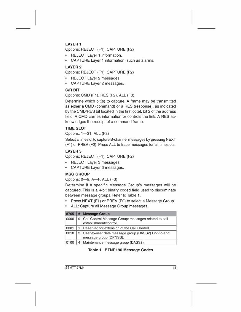
MSG GROUPOptions: 0—9, A—F, ALL (F3)Determine if a specific Message Group’s messages will becaptured. This is a 4-bit binary coded field used to discriminate betweenmessagegroups.RefertoTable1.• PressNEXT(F1)orPREV(F2)toselectaMessageGroup.• ALL:CaptureallMessageGroupmessages.
8765 # Message Group0000 0 CallControlMessageGroup:messagesrelatedtocall
establishment/control.0001 1 Reserved for extension of the Call Control.0010 2 User-to-user data message group (DASS2) End-to-end
message group (DPNSS).0100 4 Maintenance message group (DASS2).
Table 1 BTNR190 Message Codes

16 ISDN for the E1 Module
TYPE CODEOptions: 0—F, or NONE (F3)
ThemessageTypeCodediscriminatesbetweendifferentmes-sageswithinagivenmessagegroup.Itisa4-bitbinarycodedfield. The message group and message type both comprise the messageheaderoctet.The following tablegives themessagetypes for their respective groups.
Group 0000 (Call Control) Message TypesType Message Type (PBX -> ET) Message Type (ET -> PBX)
0 Initial Service Request (C) Incoming Call Indication (C)1 Initial Service Request (I) Incoming Call Indication (I)2 Recall (C) Reserved3 Recall (I) Reserved4* Reserved Channel Seized5 Call Connected Call Connected6 Reserved NetworkIndication7* Reserved Call Arrival8 ClearRequest/Confirmation Clear Indication9 Call Accepted NumberAcknowledgeA Reserved Recall RejectionB Subsequent Service Request
(I)Subsequent Call Indication
C Subsequent Service Request Subsequent Call (C) IndicationD Reserved Send Service RequestE Service Request Withheld Withhold Service RequestF Reserved Reserved
Group 0010 End-to-End DPNSS Message TypesType Message Type
2 End-to-End Message (C)3 End-to-End Message (I)4 Single Channel Clear Request Message5 Single Channel Clear Indication Message6 End-to-End Recall Message (C)7 End-to-End Recall Message (I)
Group 0010 User-to-User DASS2 Message TypesType Message Type (PBX -> ET) Message Type (ET -> PBX)
0 Swap Swap1 Reserved Reserved2 User-to-User Data (C) User-to-User Data (C)3 User-to-User Data (I) User-to-User Data (I)
4—7 Reserved ReservedGroup 0100 Maintenance Group Message Types
Group 0010 User-to-User DASS2 Message Types continues...

17SSMTT-27M4
Type Message Type (PBX -> ET) Message Type (ET -> PBX)0—2 Reserved Reserved
3 Maintenance Info Msg (C) MIM (C)4—6 Reserved Reserved
I = Incomplete C = Complete
Table 2 Message Types
SIC TYPEOptions: 0—7, ALL (F3)SelectaServiceIndicatorcodebypressingNEXT(F1)orPREV(F2). SIC TYPE indicates the type of call requested (speech or data)andisusedbytherecipientPBXtoselectanoutgoingpath.This code ensures that the selected path is capable of supporting the type of call requested. The portion of the SIC code specifying the type of data is a 3-bit binary coded field defined in BTNR 188, 190.ThesecodesareshowninTable3.
DASS2 Codes
Meaning
0 Speech
1 Speech
2 Data
3 Data
4 Teletex
5 Videotex
6 Facsimile
7 SSTV
DPNSS Codes
Meaning
1 Speech
2 Data
3 Data
4-7Data;thisisusedforinterworkingwithDASS2.Itwillbetreated as if code 2 has been received.
Table 3 DASS2 and DPNSS Codes
DA NUMBEROptions: 1—16 digit number, ALL (F3)TheDestinationAddressisadigitsequencewhichcausesacallto be routed to the correct destination, after it is sent over the networkboundary.

18 ISDN for the E1 Module
Enter the number by pressing EDIT (F1) and use the numeric keypad. If a mistake is made, press <- (F2) to the remove the selected digit and then reenter the correct number. When finished, press DONE (F1).
ETSI, AUSSI, and QSIG Filters
These filters apply to all three modes: TE, NT, and MONITOR when using ETSI, AUSSI or QIG protocols. Remember that only MONITOR is available for QSIG.
Figure 8 ETSI, AUSSI, QSIG Filter Screen
FILTER STATUSOptions: OFF (F1), ON (F2)• OFF:Allmessageswillbecapturedwithallfilteringoptions
off (not displayed).• ON:SetLayer1,2,and3filters,asexplainedasfollows.A
filterindicatorwillappearatthetopofthescreen.
FILTER STATUS-ON
LAYER 1Options: REJECT (F1), CAPTURE (F2)• REJECT:WillnotcaptureanddisplayLayer1information.• CAPTURE:CaptureanddisplayLayer1information.
Toenternumbersinthefollowingitems,pressEDIT(F1)andusethe numeric keypad. If a mistake is made, press <- (F2) to remove the selected digit, then reenter the correct number. When finished, pressDONE(F1).Notethattwoarrowkeystomovewithinthenumber, F2 and F3, may be available.
LAYER 2Options: REJECT (F1), CAPTURE (F2)• REJECTLayer2messages.• CAPTURELayer2information.
19SSMTT-27M4
LAYER 2 CAPTURE Settings
SAPIOptions: ALL (F3), any 1 or 2 digit numberAll Service Access Point Identifiers can be captured, or you may enter a specific number.
TEIOptions: ALL (F3), any 1 or 2 digit numberAll Terminal Endpoint Identifiers can be captured, or you may enter a specific number.
LAYER 3Options: REJECT (F1), CAPTURE (F2)• REJECTLayer3messages.• CAPTURELayer3information.
LAYER 3 CAPTURE Settings
CALLING #Options: ALL (F3), any 1—22 digit numberAll calling numbers can be captured by pressing ALL (F4), or enter a specific number.
CALLED #Options: ALL (F3), any 1— 22 digit numberAll called numbers can be captured by pressing ALL (F4), or enter a specific number.
CALLREFOptions: NONE (F3), any 1—5 digit number
Each call has a specific call reference value assigned to it. The value is included in the CALL SETUP message.
All Call Reference values can be captured by pressing ALL (F4), or enter a specific number.
MSG TYPEOptions: ALL (F1), SELECT (F2)
• ALL:Layer3messageswillbecaptured.• SELECT: Press and the FILTER-MESSAGETYPE screen
showninFigure9isdisplayed,whereaspecificmessagetocapture can be chosen.

20 ISDN for the E1 Module
Figure 9 Filter-Message Type Screen
Thefollowingmessagescanbecaptured:
• SETUP:Setupmessage• ALERTING:Callestablishmentalertingmessage• CALLPROC:Callproceedingmessage• CONNECT:Callconnectmessage• CONNECTACK:Connectionacknowledgedmessage• DISCONNECT:Disconnectmessage• DISCONNECTACK:Disconnectacknowledgedmessage• RELEASE:Releasecallmessage• RELEASECOMP:ReleasecompletedmessageWhen done, press ENTER to return to the FILTER screen. When you have the filters configured as desired, press ESC to return to the ISDN menu. Messages will be captured in accordancewithyourfiltersettings.Afilterindicatorwillappearatthetopofthescreen.YoucanviewcurrentmessagesintheTEMPORARYBUFFER screen.

21SSMTT-27M4
1.3.2 Live TracerObserve the live transfer of messages, on one or both lines. The ISDNTESTCONFIGURATIONMODElinemustbesettoMONI-TOR for this function to appear in the menu.IntheQSIGprotocol,onelineofsignallingandoneofuserdata,ortwolinesofsignallingcanbemonitored.MakesurethattheE1module’smainmenuTESTCONFIGURATIONscreen’sL1-RxandL2-RxPortsareset forBRIDGEorMONITOR,beforeattemptingtomonitorline1and/orline2.Ifneeded,seeSection 2.1 Configuration in the modules User’s ManualIfusingaline1configuration,allofthetracemessageswillbeL1.Ifmonitoringbothsidesofaline,L1andL2messageswillbeon separate screens. See Figure 10 for an example.
Figure 10 Live Tracer Screen
Thefollowinginformationisdisplayed:Receive information for L1, or L1 and L2 (depending on setup).Filter Indicator:“Filt”willappearatthetopofthescreeniffiltershave set up in the FILTER screen.Date: “2003-11-04”Time: “10:38:12.123”Message number: “#0785” L1/L2: The line that the message is detected, “L1” in Figure 10.C/R:TheCommand/Responsefieldbitidentifiesaframeaseithera C (Command) or a R (Response) frame, “C” in Figure 10.P/F:Poll/Finalbit(1inFigure10);incommandframes,thisistheP-bit; in response frames, it is the F-bit. When the P-bit is set to 1, it demands a response (F-bit set to 1). The F-bit is then set to

22 ISDN for the E1 Module
1 to indicate that this frame is a response from a poll command. MessageswithP-bit0donotrequirearesponseandmaybesentconsecutivelywithoutresponses.SAPI and TEIvaluesareshown.L2 MSG TYPE: Layer 2 Message Type. Figure 10 is SABME.L3 MSG TYPE:NoLayer3MessageTypeisshowninFigure10;aL3MSGTYPEwillbedisplayedifavailable.
LIVE TRACER F-keysSTOP(F1):Presstostopcapturingmessages;whenpressed,thefollowingF-keysaredisplayed: PAGE-UP (F1) and PAGE-DN(F2):Usetoviewmessages. START (F4): Restart the capturing of live messages.CLR ALL (F2): Clear the captured messages to begin tracing anew.HEX/DECODE (F3): Change the presentation of the data. The messageisshowninHEXinFigure10.
23SSMTT-27M4
1.3.3 Stored MessagesThismenuallows:
• View,filter,print,ordeletecurrentmessages• Savemessagesforfutureviewing• ViewstoredmessagesThismenucontainsthefollowing:
• TEMPORARYBUFFER• STOREDTRACES
Note:“Filt”willappearatthetopofthescreenwheninMONITORmode and filters have set up in the FILTER screen.
1.3.3.1 Temporary Buffer
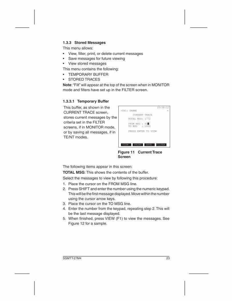
This buffer, as shown in the CURRENT TRACE screen, stores current messages by the criteria set in the FILTER screens, if in MONITOR mode, or by saving all messages, if in TE/NT modes.
Figure 11 Current Trace Screen
Thefollowingitemsappearinthisscreen:
TOTAL MSG:Thisshowsthecontentsofthebuffer.
Selectthemessagestoviewbyfollowingthisprocedure:
1. PlacethecursorontheFROMMSGline.2. PressSHIFTandenterthenumberusingthenumerickeypad.
Thiswillbethefirstmessagedisplayed.Movewithinthenumberusingthecursorarrowkeys.
3. PlacethecursorontheTOMSGline.4. Enterthenumberfromthekeypad,repeatingstep2.Thiswill
be the last message displayed.5. Whenfinished,pressVIEW(F1)toviewthemessages.See
Figure 12 for a sample.

24 ISDN for the E1 Module
Figure 12 Current Trace View Screen
ThefollowinginformationisshowninFigure12:
Date: “2003-11-04”
Time: “10:38:02.123”
Message number: “#0501”
Line used and the direction of the message: “L1 TE -> NT”
C/R:TheCommand/Responsefieldbit,whichidentifiesaframeas either a command or response in this case, C.
P/F:Poll/Finalbit(1inFigure12).SAPI and TEIvaluesareshown.
L2 MSG TYPE: The Layer 2 Message Type in Figure 12 is SABME.
L3 MSG TYPE: L3 MSG TYPE:NoLayer3MessageTypeisshowninFigure12;aL3MSGTYPEwillbedisplayedifavailable.
Current Trace F-keysPAGE-UP (F1) and PAGE-DN (F2): Use to scroll through mes-sages.
DECODE/HEX (F3): Select the display format of the data. The messageisshowninHEXinFigure12.AsampleLayer1alarmscreenisshowninFigure13.

25SSMTT-27M4
Figure 13 Layer 1 Alarm Screen
UsePAGE-UP(F1)andPAGE-DN(F2)toviewallinformation.If the messages contain an Information Element, press InfoElm (F4)todisplaythescreenshownliketheoneinFigure14.
Figure 14 Current Trace Info Element Screen
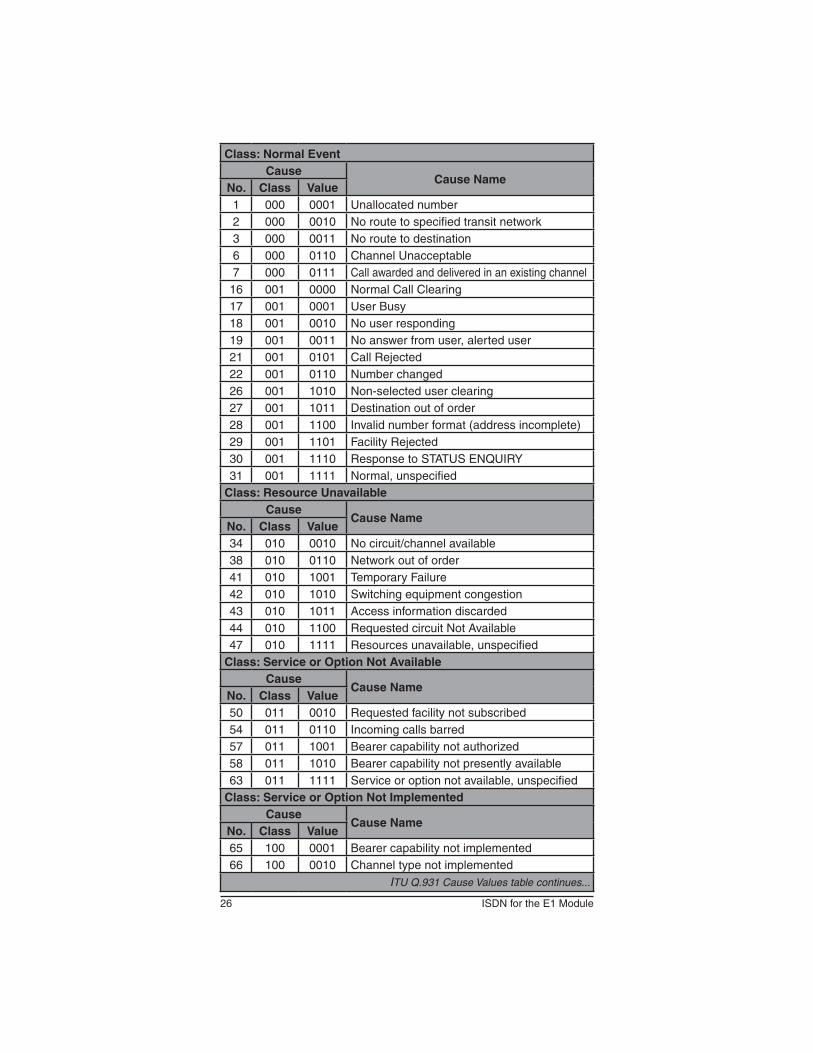
ThescreeninFigure14showsacauseelementthatprovidesdiagnosticinformation;thereasonwhyacertainmessagewasgenerated. The cause info element contains 3 main fields, Loca-tion,Class,andValue.All3fieldsaredecodedinthisscreen.Table4isalistofCauseValues,asdefiedbyITUQ.931.Press RETURN (F4) to return to the current trace.
26 ISDN for the E1 Module
Class: Normal EventCause
Cause NameNo. Class Value1 000 0001 Unallocated number2 000 0010 Noroutetospecifiedtransitnetwork3 000 0011 No route to destination6 000 0110 Channel Unacceptable7 000 0111 Callawardedanddeliveredinanexistingchannel
16 001 0000 Normal Call Clearing17 001 0001 User Busy18 001 0010 No user responding19 001 0011 Noanswerfromuser,alerteduser21 001 0101 Call Rejected22 001 0110 Number changed26 001 1010 Non-selected user clearing27 001 1011 Destination out of order28 001 1100 Invalid number format (address incomplete)29 001 1101 Facility Rejected30 001 1110 ResponsetoSTATUSENQUIRY31 001 1111 Normal, unspecified
Class: Resource UnavailableCause
Cause NameNo. Class Value34 010 0010 Nocircuit/channelavailable38 010 0110 Networkoutoforder41 010 1001 Temporary Failure42 010 1010 Switchingequipmentcongestion43 010 1011 Access information discarded44 010 1100 Requested circuit Not Available47 010 1111 Resources unavailable, unspecified
Class: Service or Option Not AvailableCause
Cause NameNo. Class Value50 011 0010 Requested facility not subscribed54 011 0110 Incoming calls barred57 011 1001 Bearer capability not authorized58 011 1010 Bearer capability not presently available63 011 1111 Service or option not available, unspecified
Class: Service or Option Not ImplementedCause
Cause NameNo. Class Value65 100 0001 Bearer capability not implemented66 100 0010 Channel type not implemented
ITU Q.931 Cause Values table continues...

27SSMTT-27M4
70 100 0110 Only restricted digital information bearer capability is available
79 100 1111 Service or option not implemented, unspecifiedClass: Invalid Message
CauseCause Name
No. Class Value81 101 0001 Invalid call reference value82 101 0010 Identified channel does not exist83 101 0011 A suspended call exists, but call id does not84 101 0100 Call identity in use85 101 0101 No call suspended86 101 0110 Call having the requested call id has been
cleared88 101 1000 Incompatible destination91 101 1011 Invalidtransitnetworkselection95 101 1111 Invalid message, unspecified
Class: Protocol ErrorCause
Cause NameNo. Class Value96 110 0000 Mandatory info element is missing97 110 0001 Message type non-existent or not imple-
mented98 110 0010 Messagenotcompatiblewithcallstate,mes-
sage type non-existent, or not implemented99 110 0011 Info element non-existent or not implemented100 110 0100 Invalid info element contents101 110 0101 Messageincompatiblewithcallstate102 110 0110 Recovery on timer expiry111 110 1111 Protocol error, unspecifiedClass: Internetworking
CauseCause Name
No. Class Value127 111 1111 Inter-working,unspecified
Table 4 ITU Q.931 Cause Values
IntheCurrentTraceViewscreenshowninFigure12,pressEN-TER to return to the CURRENT TRACE screen.These additional F-keys are available in the CURRENT TRACE screen:PRINT (F2): Send the selected results to the serial port for print-ing.YouwillenteraPRINTBUFFERscreen:

28 ISDN for the E1 Module
Figure 15 Print Buffer Screen
Select messages to be printed by using the FROM and TO lines, using the procedure given in Section 1.3.3.2. Also select:
FORMATOptions:HEX(F1),DECODE(F2),BOTH(F3)Determine the printing format.PressENTERaftermakingtheselections,andtheresultswillbesent to the serial port for printing.
SAVE (F3): Press to save the current trace in the screen to the right. Use this screen to give a label to the trace to save by using the following proce-dure.
Figure 16 Save Traces La-bel Screen
1. PressTOGGLE(F3).The“A”inthecharactergridwillbese-lectedandSELECT(F4)willappearasinFigure16.
2. Use to choose the desired character, then press SELECT (F4) to place the selected character in the LABEL line. Fornumbers,pressSHIFTandusethenumerickeypad.
Ifamistakeismade,pressTOGGLEandthenDELETE(F2)toremove the character. Use INSERT (F1) to place a character betweencharacters.

29SSMTT-27M4
3. Whenfinished,pressTOGGLE(F3)toexitthegrid.4. If needed, the numbers of the traces to be saved can be
changed at the FROM and TO lines.5. Whendone,pressENTER.Theselectedtraceswillbesaved
using the entered label in the CURRENT TRACE screen. The tracewillbesavedintothefirstavailablestoredmessageloca-tion in the STORED TRACES screen. If no space is available to save the message, “Stored Traces Full” is displayed, and a tracemustbedeletedbeforeanewtracecanbesaved.
FILTER (F4): Press FILTER to enter the FILTER screen, as in Figure 8. Here the filters can be reconfigured. After pressingENTER and return to the CURRENT TRACE screen, the TOTAL MSGnumberwillnowshowthenumberofmessagesinthebuffermatchingthefiltercriteriawheretheycanbeviewedorprinted.Thispost-filteringisavailableonlywheninTE/NTmodes.
1.3.3.2 Stored TracesThisscreenallowsaccesstostoredtraces.Theycanbeviewed,printed, or deleted in this screen.
VIEW/STORE/PRINT
SAVE
Figure 17 View/Store/Print Screen
Viewing the Current Trace1. OnenteringtheVIEW/PRINT/SAVETRACESscreenshown
in Figure 17, CURRENT is selected. This screen also presents a list of any previously stored traces.
2. ToviewtheCurrentTrace,pressVIEW(F1).TheCURRENTTRACE screen is displayed. See Section 1.3.3.1.
30 ISDN for the E1 Module
Deleting a Saved Trace1. InVIEW/PRINT/SAVETRACES,selectatracetodelete.2. PressDELETE(F2)andabriefmessageisdisplayedwarning
about the deletion.3. TodeletetheCURRENTtrace,pressCLEAR(F2)withCUR-
RENTselected.Clearingthenewtraceallowscapturingnewtraces, so that only the current messages are displayed.
Saving a Trace1. TherearetwowaystosavetheCurrentTrace:
A. Selectanemptynumberslot in theVIEW/PRINT/SAVETRACESscreenandpressSAVE(F4).
B. IntheVIEW/PRINT/SAVETRACESscreen,withCURRENTselected,pressSAVE(F4).
2. TheSAVETRACESlabelscreenisthendisplayed,asinFig-ure16.HeregivethetracealabelbyusingtheproceduresfollowingFigure16.
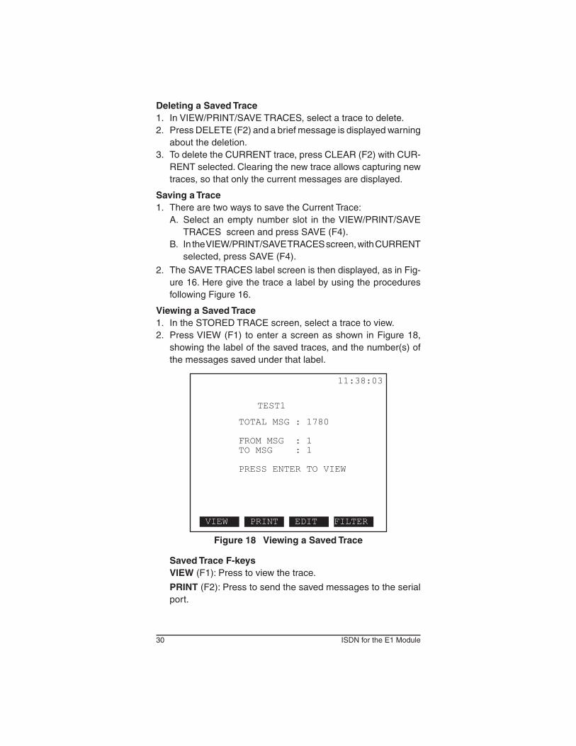
Viewing a Saved Trace1. IntheSTOREDTRACEscreen,selectatracetoview.2. PressVIEW(F1) toenterascreenasshown inFigure18,
showingthelabelofthesavedtraces,andthenumber(s)ofthe messages saved under that label.
Figure 18 Viewing a Saved Trace
Saved Trace F-keysVIEW (F1):Presstoviewthetrace.
PRINT (F2): Press to send the saved messages to the serial port.

31SSMTT-27M4
EDIT(F3):PresstoreturntotheSAVETRACESlabelscreenwherethenameofthesavedtracecanbechanged.SeeFigure16andtheexplanationfollowingit.
FILTER (F4): Press to redefine and reapply the filters to the saved trace in the FILTER screen. See Figure 8 and the de-scriptionfollowingitforinstructionsonsettingupfilters.Thisprocedure is referred to as post-filtering.
3. PressVIEW(F1) toview thesaved trace.Thescreensarescreens described in Section 1.3.3.1.
Printing a Trace1. PressPRINT(F3)andaPRINTBUFFERscreen,asshown
in Figure 15, is displayed.2. SelectthemessagestobeprintedattheFROMMSGandTO
MSGlines.3. At theFORMATline,choosewhethertoprint theresults in
HEX,DECODE,orBOTH.4. Press ENTER to print the results.5. PressRETURNtoreturntoVIEW/PRINT/SAVETRACES.
32 ISDN for the E1 Module
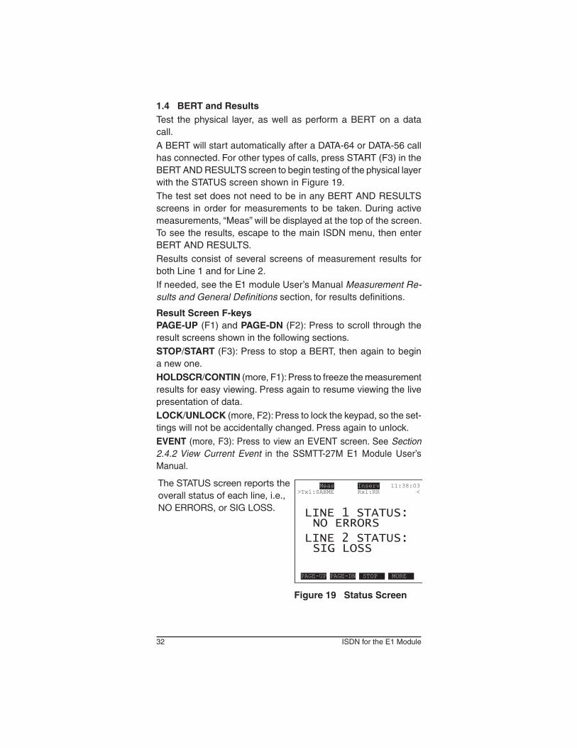
1.4 BERT and ResultsTest thephysical layer,aswell asperformaBERTonadatacall.ABERTwillstartautomaticallyafteraDATA-64orDATA-56callhas connected. For other types of calls, press START (F3) in the BERT AND RESULTS screen to begin testing of the physical layer withtheSTATUSscreenshowninFigure19.The test set does not need to be in any BERT AND RESULTS screens in order for measurements to be taken. During active measurements,“Meas”willbedisplayedatthetopofthescreen.To see the results, escape to the main ISDN menu, then enter BERT AND RESULTS.Results consist of several screens of measurement results for both Line 1 and for Line 2.If needed, see the E1 module User’s Manual Measurement Re-sults and General Definitions section, for results definitions.
Result Screen F-keysPAGE-UP (F1) and PAGE-DN (F2): Press to scroll through the resultscreensshowninthefollowingsections.STOP/START (F3): Press to stop a BERT, then again to begin anewone.HOLDSCR/CONTIN (more, F1): Press to freeze the measurement resultsforeasyviewing.Pressagaintoresumeviewingthelivepresentation of data.LOCK/UNLOCK (more, F2): Press to lock the keypad, so the set-tingswillnotbeaccidentallychanged.Pressagaintounlock.EVENT(more,F3):PresstoviewanEVENTscreen.SeeSection 2.4.2 View Current Event in the SSMTT-27M E1 Module User’s Manual.
The STATUS screen reports the overall status of each line, i.e., NO ERRORS, or SIG LOSS.
Figure 19 Status Screen

33SSMTT-27M4
The SUMMARY screen reports on measurement data for specific types of E1 signal errors, i.e., code or framing. Counts are shown on th eright and rates are on the left for most measurements.
The FREQUENCY screen reports on relevant frequency information.
The ALM/SIG screen reports on line alarm and measurement parameters.
Figure 20 BERT Result Screens

34 ISDN for the E1 Module
Thefollowingareavailableifthespecificmeasurement(suchasM.2100orG.826)isturnedoninE1MODULEmainmenu>SYS-TEMPARAMETERS>MEASCONFIGURATIONscreentwo.
The M2100/550 screen reports on PASS/FAIL measurements in accordance with ITU-T M.2100/550.
The G.826 screen reports measurements relating to block-based ITU-T G.826.
The G.821 screen reports measurements specified in ITU-T G.821, as well as their related percent values.
Note that the B-channel is indicated in the forth line below the header in this screen (BCH:31).
Figure 21 Optional BERT Result Screens
35SSMTT-27M4
1.5 Automatic TestScanforavarietyofHLCandSupplementaryservicesplacingsequential and bulk calls. The test set must be in TE or NT mode for this menu selection to be available. The menu screen contains:• AUTO SCAN• SUPPSERVICESSCAN• SEQUENTIALCALL• BULKCALL
1.5.1 Auto Scan
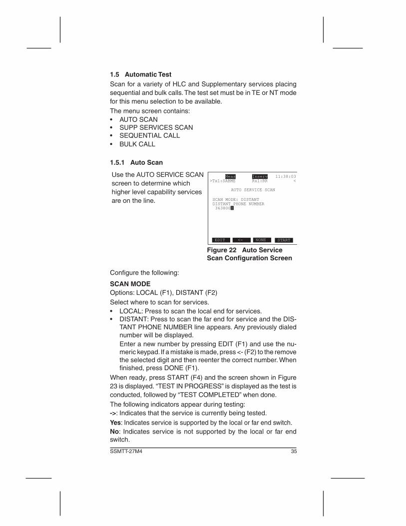
Use the AUTO SERVICE SCAN screen to determine which higher level capability services are on the line.
Figure 22 Auto Service Scan Configuration Screen
Configurethefollowing:
SCAN MODEOptions: LOCAL (F1), DISTANT (F2)Selectwheretoscanforservices.• LOCAL:Presstoscanthelocalendforservices.• DISTANT:PresstoscanthefarendforserviceandtheDIS-
TANTPHONENUMBERlineappears.Anypreviouslydialednumberwillbedisplayed.
EnteranewnumberbypressingEDIT(F1)andusethenu-meric keypad. If a mistake is made, press <- (F2) to the remove the selected digit and then reenter the correct number. When finished, press DONE (F1).
Whenready,pressSTART(F4)andthescreenshowninFigure23isdisplayed.“TESTINPROGRESS”isdisplayedasthetestisconducted,followedby“TESTCOMPLETED”whendone.Thefollowingindicatorsappearduringtesting:->: Indicates that the service is currently being tested.Yes:Indicatesserviceissupportedbythelocalorfarendswitch.No: Indicates service is not supported by the local or far end switch.
36 ISDN for the E1 Module
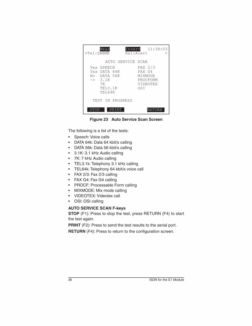
Figure 23 Auto Service Scan Screen
Thefollowingisalistofthetests:
• Speech:Voicecalls• DATA64k:Data64kbit/scalling• DATA56k:Data56kbit/scalling• 3.1K:3.1kHzAudiocalling• 7K:7kHzAudiocalling• TEL3.1k:Telephony3.1kHzcalling• TEL64k:Telephony64kbit/svoicecall• FAX2/3:Fax2/3calling• FAXG4:FaxG4calling• PROCF:ProcessableFormcalling• MIXMODE:Mixmodecalling• VIDEOTEX:Videotexcall• OSI:OSIcalling
AUTO SERVICE SCAN F-keysSTOP (F1): Press to stop the test, press RETURN (F4) to start the test again.
PRINT (F2): Press to send the test results to the serial port.
RETURN (F4): Press to return to the configuration screen.

37SSMTT-27M4
1.5.2 Supplementary Services Scan
This function can verify which supplementary services are available on the line. A number must be entered in MY PHONE NUMBER in the ISDN TEST CONFIGURATION screen to conduct this scan.
Figure 24 Supplementary Service Scan Configuration Screen
Configurethefollowing:
MSNOptions: Any 1—20 digit numeric entryIf desired, enter a Multiple Subscriber Number to scan. This is the number that is tested for services. Press NONE (F3) to not test.Enter a number used to place the call by pressing EDIT (F1) and use the numeric keypad. If a mistake is made, press <- (F2) to the remove the selected digit and then reenter the correct number. When finished, press DONE (F1)
Press START (F4) to begin the scan and the test set will place a self call sending appropriate messages to the switch. When it gets a response from the switch, it then reports Ok or No. -> means in progress as shown in the screen to the right.
Figure 25 Supplementary Services Scan Screen
Hereisalistoftheservicestested:
CLIP: Calling Line Identification Presentation presents the calling party number to the called user.
CLIR: Calling Line Identification Restriction prevents the calling partynumberfrombeshowedtothecalleduser.
CFU:CallForwardingUnconditionaldivertsareceivedcalltoaspecified different number.
38 ISDN for the E1 Module
COLP: Connected Line Identification Presentation displays the answeringparty’snumbertothecallingparty.
COLR:ConnectedLineIdentificationRestrictionallowsthecalledsubscriber to stop COLP from operating.
CFB:CallForwardingBusyCallsareforwardedtoaspecifiednum-beronlywhenthesubscriber’s(calledparty)numberisbusy.
SUB: Sub Address is a digit is added to an incoming call to specify an extension.
MSN: Multiple Subscriber Number – multiple full numbers are assigned to one BRI line.
CFNR:CallForwardingNoReply–Callsareforwardedtoaspeci-fiednumberonlywhenthesubscriber(calledparty)doesnotpickup the line in a specified amount of time.
DDI: Direct Dialing In adds a number of telephone numbers to acircuitwhichcanbeusedtodialthatBRI(commonuseisacompanynumberwithindividual4digitextensionnumbersthatcan be dialed).
CH:CallHold–theusermayinterruptandplaceacallonhold,then reestablish it later. Interruption frees the associated B-channel.
UUS:UsertoUserSignallingallowsausertosendaninforma-tion message in the Setup, Alerting, or Connect messages on theD-channel,withoutconnectingthecall;themessageshowson the ISDN phone display.
TP: Terminal Portability is the ability to suspend and reconnect a call; for example, to move a phone from one outlet to another.
AOC-D/E/S:AdviceofChargedetermineswhatcharginginvoca-tions are available; Duration, End, Start (charged per a certain amount of time at the beginning of the call).
MCID: Malicious Call Identification – the called party, on a per call basis, requests the caller to transmit their phone number, the number they are calling, and the date and time of the call.
CUG:ClosedUserGroup–providesaprivatenetworkrestrictingcommunicationsbetweenmembersandnonmembers.
SUPPLEMENTARY SERVICES SCAN F-keysSTOP (F1): Stop the test, press RETURN (F4) to start the test again.
PRINT (F2): Send the test results to the serial port for printing.
RETURN (F4): Return to the configuration screen.
39SSMTT-27M4
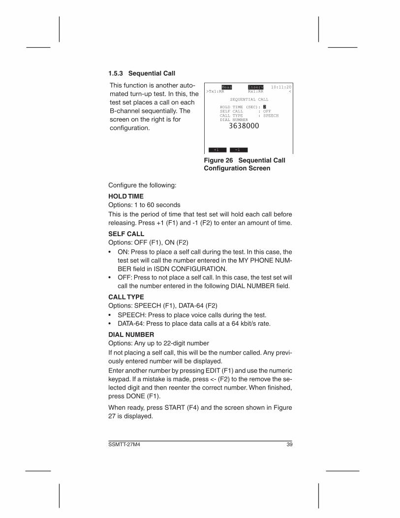
1.5.3 Sequential Call
This function is another auto-mated turn-up test. In this, the test set places a call on each B-channel sequentially. The screen on the right is for configuration.
Figure 26 Sequential Call Configuration Screen
Configurethefollowing:
HOLD TIMEOptions: 1 to 60 secondsThisistheperiodoftimethattestsetwillholdeachcallbeforereleasing. Press +1 (F1) and -1 (F2) to enter an amount of time.
SELF CALLOptions: OFF (F1), ON (F2)• ON:Presstoplaceaselfcallduringthetest.Inthiscase,the
testsetwillcallthenumberenteredintheMYPHONENUM-BERfieldinISDNCONFIGURATION.
• OFF:Presstonotplaceaselfcall.Inthiscase,thetestsetwillcallthenumberenteredinthefollowingDIALNUMBERfield.
CALL TYPEOptions:SPEECH(F1),DATA-64(F2)• SPEECH:Presstoplacevoicecallsduringthetest.• DATA-64:Presstoplacedatacallsata64kbit/srate.
DIAL NUMBEROptions: Any up to 22-digit numberIfnotplacingaselfcall,thiswillbethenumbercalled.Anyprevi-ouslyenterednumberwillbedisplayed.Enter another number by pressing EDIT (F1) and use the numeric keypad. If a mistake is made, press <- (F2) to the remove the se-lected digit and then reenter the correct number. When finished, press DONE (F1).
Whenready,pressSTART(F4)andthescreenshowninFigure27 is displayed.

40 ISDN for the E1 Module
Figure 27 Sequential Call Screen
Thisscreenshowsthestatusofall30B-channels.Notethatchan-nel 16 is marked as the D-channel. Each channel may display oneofthefollowingstatusmessages:
PASS: A call has been successfully connected and released.
FAILED:Acallwasattempted,butwasnotsuccessful.
CALL: A call is being placed for this channel.
HOLD: A call is still in progress on this channel.
A blank space indicates that a call has not yet been attempted for that channel.
SEQUENTIAL CALL F-keysSTOP (F1): Stop the test, press RETURN (F4) to start the test again.
PRINT (F2): Send the test results to the serial port for printing.
RETURN (F4): Return to the configuration screen.

41SSMTT-27M4
1.5.4 Bulk CallThis feature is another automated test that stresses the PRI circuit toseehowmuchtrafficitcanhandle.TheISDNTESTCONFIGURATIONshouldbesetupinTEmodeus-ingETSIprotocol.AtMYPHONENUMBER,enterthenumberofthelinethatthecalliscomingfrom.L1-RXshouldbesetforTERM.
This BULK CALL screen is for configuration and is displayed after selecting BULK CALL.
Note: To enter numbers, press EDIT (F1) and use the numeric keypad. If a mistake is made, press <- (F2) to the remove the selected digit and then reenter the correct number. When finished, press DONE (F1).
Meas Inserv 10:11:20>Tx1:RR Rx1:RR < BULK CALL
NUMBER OF CALLS(1-99999): 30 SELF CALL : OFF CALL RATE(1-180/min) : 150 CALL TYPE : DATA-64 DIAL NUMBER
3603500
EDIT <- START
Figure 28 Bulk Call Con-figuration Screen
Configurethefollowing:
NUMBER OF CALLS (1-99999)Options: 1—99999, default is 30Determine the number of calls that are generated during the test.
SELF CALLOptions: OFF( F1), ON (F2)Determineifthetestsetwillplaceaselfcall.• ON:Placesaselfcallduringthetest.Inthiscase,thetestset
willcalltheCALLERNUMBERenteredintheISDNCONFIGU-RATION screen. If used, CALL RATE is a maximum of 90.
• OFF:Aselfcallisnotmade.Inthiscase,thetestsetwillcallthe number entered as DIAL NUMBER in this screen.
CALL RATE (1-180/min)Options: 1—180 per minute; default is 150Specify the call rate. For example, in Figure 28, the number of calls is30andCALLRATEis60.Thismeansthat60callswillbesetupandreleasedperminute,andthetestwillrunfor3minutes.
CALL TYPEOptions:SPEECH(F1),DATA-64(F2)Determine the call type.
DIAL NUMBERIfnotplacingaselfcall,thiswillbethenumbercalled.Whenfinished,pressSTART(F4)whenDIALNUMBERisse-lectedandthescreenshowninFigure29isdisplayed.

42 ISDN for the E1 Module
In the BULK CALL TESTING screen, simultaneously view the live activity of all B channels.
“V” (Valid) indicates there is an active call connected on that particular B channel.
“D” indicates the D-channel. The following provides a running count of the status of the calls:
Meas Inserv 10:11:20>Tx1:RR Rx1:RR < BULK CALL TESTING 1: 2:V 3:V 4: 5: 6:V 7:V 8: 9: 10: 11: 12:V 13: 14:V 15: 16:D 17: 18: 19: 20: 21: 22: 23: 24: 25: 26: 27: 28: 29: 30: 31: ACTIVE CALLS : 6 CALLS COMPLETED : 16 TOTAL CALLS : 30
RESULT STOP
Figure 29 Bulk Call Testing Screen
ACTIVE CALLS: Number of calls that are currently connected.CALLS COMPLETED: Number of calls that have been success-fully completed.TOTAL CALLS: Total number of calls placed and received. On a selfcall,thisnumberwillbedoubletheNUMBEROFCALLSsetupintheBULKCALLconfigurationscreen.Inapoint-to-pointcall,this is the number of calls placed, as none are received.
BULK CALL TESTING F-keysSTOP (F4) Press to stop the test. To restart testing, press ESC to returntotheBULKCALLconfigurationscreenandpressSTART(F4).RESULT(F1):PresstoviewtheBULKCALLRESULTscreen1showninFigure30.
This BULK CALL RESULT screen reports:
ORIGINATING CALLS: Number of test set genereated call setup messages.
TERMINATING CALLS: Number of received call setup messages.
COMPLETED CALLS: Number of calls successfully connected and released.
DISC CAUSE VALUES: Discon-nect cause values for each call are decoded. In this screen, calls were 16, Normal Call Clearing and 17 User Busy.
Meas Inserv 10:11:20>Tx1:RR Rx1:RR < BULK CALL RESULT ORIGINATING CALLS : 180 TERMINATING CALLS : 0 COMPLETED CALLS : 24
DISC CAUSE VALUES: 16 Normal Call Clearing 17 User Busy
PAGE-DN PRINT RETURN
Figure 30 Bulk Call Result Screen 1
BULK CALL RESULT F-keysPAGE-UP (F1) PAGE-DN(F2):Usetovieweachscreen.NotethereisnoPAGE-UPinscreen1PRINT (F3): Send the results to the serial port.RETURN (F4): Return to configuration screen.

43SSMTT-27M4
PressPAGE-DN(F2)toviewthenextscreen.
This screen reports the number of completed calls for each channel (time slot 1—31).
Press PAGE-DN (F3) to view the next screen.
Meas Inserv 10:11:20>Tx1:RR Rx1:RR <CHANNELS USED: 1- 1 2- 2 3- 1 4- 2 5- 2 6- 2 7- 1 8- 2 9- 1 10- 1 11- 1 12- 1 13- 2 14- 0 15- 0 16- D 17- 0 18- 0 19- 0 20- 0 21- 2 22- 0 23- 1 24- 0 25- 0 26- 0 27- 1 28- 0 29- 1 30- 0 31- 0 PAGE-DN PRINT RETURN
Figure 31 Bulk Call Result Screen 2
This screen reports the date and time of day for the start and end of the test.
Note: Depending on the DISC CAUSE VALUES in screen 1, some information may run on to other screens.
Meas Inserv 10:11:20>Tx1:RR Rx1:RR <
START TIME: 2007-06-28 10:10:01 END TIME : 2007-06-28 10:10:11
PAGE-UP PRINT RETURN
Figure 32 Bulk Call Result Screen 3
When finished, press RETURN (F4) to view the configurationscreen.

44 ISDN for the E1 Module
45SSMTT-27M4
2 Applications
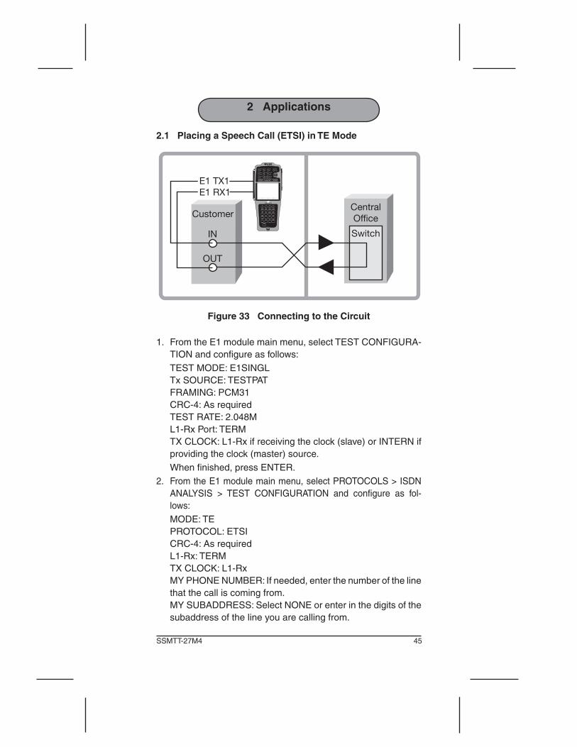
2.1 Placing a Speech Call (ETSI) in TE Mode
Customer
E1 TX1E1 RX1
IN
OUT
CentralOffice
Switch
Figure 33 Connecting to the Circuit
1. FromtheE1modulemainmenu,selectTESTCONFIGURA-TIONandconfigureasfollows:
TESTMODE:E1SINGL Tx SOURCE: TESTPAT FRAMING:PCM31 CRC-4: As required TEST RATE: 2.048M L1-Rx Port: TERM TXCLOCK:L1-Rxifreceivingtheclock(slave)orINTERNif
providing the clock (master) source. When finished, press ENTER.2. From the E1 module main menu, select PROTOCOLS > ISDN
ANALYSIS > TEST CONFIGURATION and configure as fol-lows:
MODE: TE PROTOCOL: ETSI CRC-4: As required L1-Rx: TERM TXCLOCK:L1-Rx MYPHONENUMBER:Ifneeded,enterthenumberoftheline
that the call is coming from. MY SUBADDRESS: Select NONE or enter in the digits of the
subaddress of the line you are calling from.

46 ISDN for the E1 Module
Configurethesecondscreenasfollows: LAYER 2 TEI: 0 (or as required) SIGNALLINGT/S:16 AUTO ANSWER: OFF ANSWER TYPE: NORMAL When finished, press ENTER.3 ConnectthetestsettothelineasshowninFigure33.4. From the ISDN menu, select CALL CONTROL and verify that
an in service message is displayed. This indicates that the Layer 2 handshake has taken place, and the test set is ready to place and receive calls.
5. Press CALL (F2 or F4) and the CALL SETUP screen is dis-played,configureasfollows:
CALLTYPE:SPEECH BCHANNEL:AUTO TESTPATTERN:N/A UUS: NONE DIALNUMBER:Enterthenumbertocall,usingSHIFTand
the numeric keypad. SUBADDRESS: NONE, or as appropriate. This is the subad-
dressassociatedwiththenumberthatisreceivingthecall. Whenfinished,pressENTERandthecallwillbeplaced.You
should be able to talk and listen on the selected timeslot.6. Press ESC to return to the CALL CONTROL screen. There
thestatusofthecall(s)maybeviewed,andthecallcanbeendedbypressingON-HOOK.
2.2 Placing a Data Call and Running a BERT1. In Section 2.1,performsteps1—5andconfigureasfollows: CALL TYPE: DATA-64 BCHANNEL:AUTO TEST PATTERN: 2047, used to qualify ISDN lines. UUS: NONE DIAL NUMBER: Enter the number to call. SUBADDRESS: NONE, or as appropriate, this is the subad-
dressassociatedwiththenumberyouarecalling. Whenfinished,pressENTERandthecallwillbeplaced.When
connected,youwillhearthedataonthetestset’sspeaker.2. Press ESC to reach the ISDN menu and select BERT AND
RESULTS. The BERT should have begun. Use PAGE-UP(F1)andPAGE-DN(F2)toviewtheresultsscreens.Verifythemeasurements meet your requirements.

47SSMTT-27M4
2.3 Placing a Second CallTo place a second call, simply press the second CALL F-key in the CALL CONTROL screen, and repeat the CALL SETUP procedure.
Notes: • TheB-channelmayneedtobechanged,ifnotautomatically
choosing them. • Two speech calls can be placed, or one data and one
speech.
2.4 Receiving a CallIntheISDNCONFIGURATIONscreen,determinehowthetestsetwillansweracallattheAUTOANSWERline.
AUTO Answer ONThetestsetwillacceptanyreceivedcall. Itwill loopthecall ifANSWER TYPE is set to LOOP, or terminate the call if ANSWER TYPE is set to NORMAL.
AUTO Answer OFFWhenreceivinganincomingcall,thetestsetwillnotifyyouofanincomingcallbyringinganditwilldisplaytheCALLCONTROLscreen. Press ACCEPT (F1 or F3) to accept the call and go off-hook, or press REJECT (F2 or F4) to not accept the call, and remain on-hook.
2.5 Running a Supplementary Services ScanThisscansalinetoseewhichservicesareavailable.1. In Section 2.1, perform steps 1—4. Note:AnumbermustbeenteredattheMYPHONENUMBER
lineintheISDNCONFIGURATIONscreen.2. From the ISDN menu, select AUTOMATIC TEST > SUPP
SERVICESSCAN.AttheMSNline,enteraMultipleSubscriberNumber to scan, if you have one you need to test for services, if not press NONE (F3).
3. PressSTART(F4)andthetestsetwillplacetheselfcall.Itsendsappropriatemessagestotheswitchtocheckforeachsupplementaryservice.Theswitchthenrespondsconfirmingor rejecting the service.
The test set then displays the appropriate “Ok” or “No” for each service. When the scan has finished, “TEST COMPLETED” is displayed. See Section 1.5.2 for an explanation of the services tested.

48 ISDN for the E1 Module
2.6 Running an Auto Service ScanScanalinetofindoutwhichbearerservicesareavailableonthecircuit.Followthisproceduretocheckifthecircuitisprovisionedforspeech,data,3.1Kor7Kaudio,orHLCcalltypes.1. In Section 2.1, perform steps 1—4 andwait for the link to
initialize.Youwillseeaninservicemessageatthetopofthescreenwhenthelinkisup.
2. From the ISDN menu, select AUTOMATIC TEST > AUTO SERVICESCANandconfigurethescreenasfollows:
SCAN MODE: Choose a local or a distant scan: LOCAL: Use to scan your circuit for services. DISTANT: Use to scan another circuit for service.
DISTANT PHONE NUMBER (if DISTANT was selected forSCAN MODE): Enter a number to dial or use the existing one.
3. PressSTART(F4)tobeginandascreenwillappearshowingthestatusofeachbearerservice.Thetestsetwillreport“TESTCOMPLETED”whenalloftheserviceshavebeentestedfor.See Section 1.5.1 for more information.
2.7 Running a Sequential Call TestSequential Call is an automated PRI turn-up test. During the test, the test set places a call on each B-channel sequentially, and dis-playswhethereachB-channelhadasuccessfulorfailedcall.1. In Section 2.1, perform steps 1—4 andwait for the link to
initialize.Inservicewillbedisplayedwhenthelinkisup.2. FromtheISDNmenu,selectAUTOMATICTEST>SEQUEN-
TIALCALLandconfigureasfollows: HOLDTIME:3(thiswillkeepeachcallupfor3secondsbefore
releasing; you may enter any value from 1 to 60 seconds.) SELFCALL:OFF(F1)orON(F2),dependingonifyouwant
tocallanothernumber,oryourown.IfyouchooseON,thetestsetwillcalltheCALLERNUMBERenteredintheISDNTESTCONFIGURATIONscreen.IfyouchooseOFF,thetestsetwillcallthenumberenteredinDIALNUMBER.
CALLTYPE:SPEECHorDATA-64 DIAL NUMBER: Enter the number to call, if not using Self call. When finished, press START (F4) and a sequential call results
screen appears, showing the status of each B-channel. Ifneeded, refer to Section 1.5.3 for information on the results.
3. Whendone,pressSTOP(F1).PressRETURN(F4)toviewtheconfigurationscreen,whereanewtestcanbestarted.

49SSMTT-27M4
3 Reference
3.1 ISDN Technology OverviewISDN (Integrated Services Digital Network) was conceived toprovidedigitalservicestoresidentialandbusinesscustomers.Twoconfigurationsweredesigned,2B+DforBRI(BasicRateInterface)and 30B+D for high speed PRI (Primary Rate). Each B-channel has64kbit/savailabilityforvoiceordatatransport.TheD-channelis used for signalling and data communication; its capacity for BRI andPRIis16kbit/sand64kbit/srespectively.Using ISDN, users can transport data at a higher rate in addition toutilizingavarietyofnewservicessuchasGroupIVFAXandpersonal digitialized video communication.
3.1.1 ISDN Network Architecture
Figure 34 ISDN Network Architecture
InthenetworkshowninFigure34,anISDNusercanaccessthefollowingservicesusinganISDNTE(TerminalEquipment):• PacketSwitcheddata• CircuitSwitcheddata• CircuitSwitchedvoice• CommonChannelSignalling• User-to-Usersignaling
50 ISDN for the E1 Module
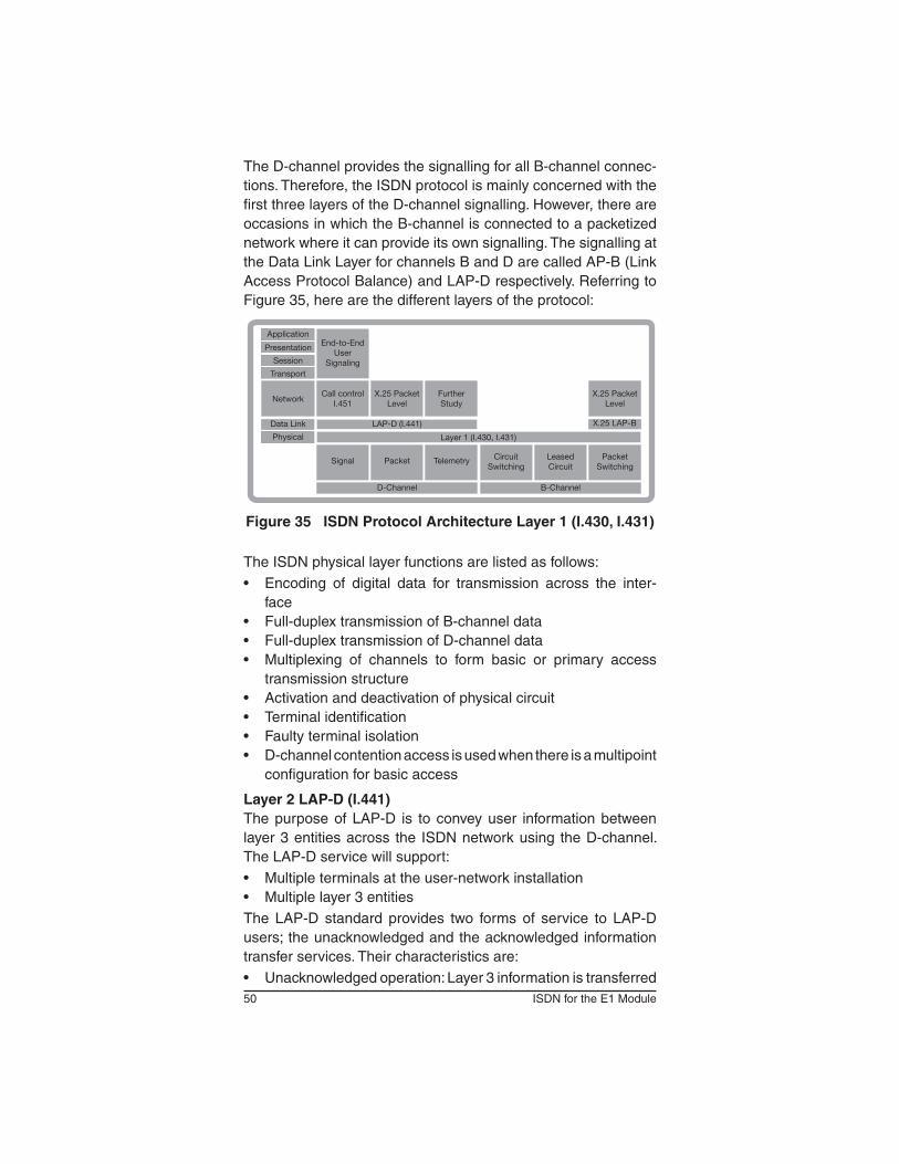
The D-channel provides the signalling for all B-channel connec-tions.Therefore,theISDNprotocolismainlyconcernedwiththefirstthreelayersoftheD-channelsignalling.However,thereareoccasionsinwhichtheB-channelisconnectedtoapacketizednetworkwhereitcanprovideitsownsignalling.Thesignallingatthe Data Link Layer for channels B and D are called AP-B (Link Access Protocol Balance) and LAP-D respectively. Referring to Figure 35, here are the different layers of the protocol:
X.25 Packet Level
Application
Presentation
Session
Transport
Network
Data Link
Physical
End-to-End User
Signaling
Call control I.451
X.25 Packet Level
Further Study
X.25 LAP-BLAP-D (I.441)
Layer 1 (I.430, I.431)
Signal Packet Telemetry Circuit Switching
Leased Circuit
Packet Switching
D-Channel B-Channel
Figure 35 ISDN Protocol Architecture Layer 1 (I.430, I.431)
TheISDNphysicallayerfunctionsarelistedasfollows:• Encoding of digital data for transmission across the inter-
face• Full-duplextransmissionofB-channeldata• Full-duplextransmissionofD-channeldata• Multiplexing of channels to form basic or primary access
transmission structure• Activationanddeactivationofphysicalcircuit• Terminalidentification• Faultyterminalisolation• D-channelcontentionaccessisusedwhenthereisamultipoint
configuration for basic access
Layer 2 LAP-D (I.441)ThepurposeofLAP-D is toconveyuser informationbetweenlayer3entitiesacross the ISDNnetworkusing theD-channel.TheLAP-Dservicewillsupport:• Multipleterminalsattheuser-networkinstallation• Multiplelayer3entitiesThe LAP-D standard provides two forms of service to LAP-Dusers;theunacknowledgedandtheacknowledgedinformationtransfer services. Their characteristics are:• Unacknowledgedoperation:Layer3informationistransferred

51SSMTT-27M4
in unnumbered frames. Error detection is used to discard dam-agedframes,butthereisnoerrorcontrolorflowcontrol.
• Acknowledgedoperation:Layer3informationistransferredinframesthatincludesequencenumbersandthatareacknowl-edged.Errorcontrolandflowcontrolproceduresareincludedin the protocol. This type is also referred to in the standard as multiple-frame operation.
ThetwotypesofoperationmaycoexistonasingleD-channel.Withtheacknowledgedoperation,itispossibletosimultaneouslysupport multiple logical LAP-D connections. This is analogous to theabilityinX.25level3tosupportmultiplevirtualcircuits.
Layer 3For call control signalling, the D-channel layer 3 interface is defined in I.450 and I.451. This specifies the procedures for establishing connections on the B-channels that share the same interface to ISDN as the D-channel. It also provides user-to-user control signalling over the D-channel. Asmentionedbefore,packetswitchingsignallingisalsoavailableusingX.25layer3protocol.ThisisthesameforusingB-channelpacketswitchingservice.Layer 3 provides higher layer information for supporting various ISDNfunctions.Twobasictypesofuserterminalsaresupportedby ISDN: • Functionalterminals:Theseareconsideredtobeintelligent
devices and can employ the full range of I.451 messages and parameters for call control. All signaling information is sent in a single control message (en bloc sending).
• Stimulus terminals: These are devices with a rudimentarysignaling capability. A simple digital telephone is an example of a stimulus terminal.

52 ISDN for the E1 Module
3.1.2 ISDN Messages and their FunctionsThereisan8bitflagattheendofeachframe,asshowninFigure36. Sixteen bits are used for frame checking.
8Address
16Control8 or16
Information Variable(0-65)
FCS16 8
1 1 MM P/F MMM U
1 0 SS 0000 P/F N(R) S
0 C/R N(S) P/F N(R) S
0 C/R SAPI 1 TEI
Figure 36 ISDN Frame Structure
ThefollowingitemsareshowninFigure36.
AddressThe Address is composed of:• TEI(TerminalEndpointIdentifier):Identifiestheuserdevice.• SAPI(ServiceAccessPointIdentifier):Identifiesalayer3user
of LAP-D, and thus corresponds to a layer 3 protocol entity withinauserdevice.Fourvalueshavebeenassigned:- 0: used for call control procedures for managing B-channel
circuits- 16: reserved for packet-mode communication on the D-
channelusingX.25level3- 63: used for the exchange of layer 2 management informa-
tion- 1: used for packet-mode communication using I.451. This
can be used for user-user signallingThe combination of TEI and SAPI is referred to as DLCI (Data Link Connection Identifier). At any one time, LAP-D may maintain multiplelogicalconnections,eachwithauniqueDLCI.
ControlLAP-Ddefinesthreetypesofframes,eachwithadifferentcontrolfield format:• Information transfer frames (I-frames) carry the data to be
transmitted for theuser.Additionally, flowanderror controldata,usingthego-back-NARQ(AutomaticRepeatRequest)mechanism, are piggybacked on an information frame.

53SSMTT-27M4
• Supervisoryframes(S-frames)providetheARQmechanismwhenpiggybackingisnotused.
• Unnumbered frames (U-frames) provide supplemental linkcontrolfunctionsandarealsousedtosupportunacknowledgedoperation.
Allofthecontrolfieldformatscontainthepoll/finalbit(P/F).Incommand frames, it is referred to as the P-bit, and is set to 1 to solicit (poll) a response frame from the peer LAP-D entity. In response frames, it is referred to as the F-bit, and is set to 1 to indicate the response frame transmitted as a result of a soliciting command.
InformationThe information field is present only in I-frames and some unnum-bered frames. In the case of both control signalling and packet information, maximum length is 260 octets. The information field contains the message type and parameters. For example, the SETUP message is used to set up a call. It contains the bearer capability,originatinganddestinationaddresses,transitnetworkselection and other pertinent data. Layer 3 information is used for intra,aswellasinterexchangecallsusingSS7.
Basic Call SequenceFigure 37 illustrates the basic ISDN call sequence.
TE NT TESetup
Call Proceding
Alerting
Connect
Connect Ack.
-Call-
Disconnect
Release
Release Complete
Setup
Call Proceding
Alerting
Connect
Connect Ack.
-Call-
Disconnect
Release
Release Complete
Terminal TerminalNetwork
Figure 37 ISDN Basic Call Sequence

54 ISDN for the E1 Module
3.1.3 DASS2 TechnologyDigital Access Signalling System 2 (DASS2) is a common chan-nelsignallingsystemintendedforusebetweenthecustomer’sequipment(PBX)andanISDNlocalexchange.DASS2isspeci-fied in BNR 190 (British Telecom). A 2.048 Mbps line connects thePBXstotheISDNexchange.This2.048M,32-timeslotsignalisdividedasfollows:
30x64Kbps CircuitSwitchedTrafficChannels (Timeslots 1—15 and 17—31)
1x64Kbps Frame Alignment Signal (Timeslot 0)
1x64Kbps Signalling Channel (Timeslot 16)
Thecommonchannelsignalling(LinkAccessProtocol)isalwayscarried on timeslot 16; no other timeslots are used for DASS2 signalling. DASS2 is based on the first three layers of the ISO referencemodel.Layer1,PhysicalLayer,involvestheactivating/deactivating of the physical connection. Layer 2, Link Access Protocol, provides secure, error-free transmission of the Layer 3 messages.Layer3,CallHandlingLayer,containsthecallcon-trolmessagesconveyedwithinaHLDC(HighLevelDataLink)standard frame.
3.1.3.1 DASS2 Layer 2Layer 2, the Data Link layer, provides a transport mechanism for layer 3 messages. Link Access Protocol (LAP) operates in paral-lelwitheachotheroverthesignallingchannel(timeslot16).LAPcontroliseffectedusingoneofthetwoframeformatsshowninFigure 38.
FCS16 bits
Information Variable(0-12)
Control8 bits
Address16 bits
FCS16 bits
Control8 bits
Address16 bits
Figure 38 LAP Frame Structure
Inbrief,theLAPfieldsshowninFigure38are:Address: This is transmitted first and contains 2 octets. It identi-fiesthetrafficchannel(carriedontimeslot0)associatedwithitssignalling frame.Control: This is transmitted second and is one octet long. It contains a frame type code and, sometimes, a sequence number.

55SSMTT-27M4
Information:ThisisnotalwayspresentinaLAPframe.Ifitisitcontainsaninformationblock,0—45octetslong,whichistrans-ferred transparently across the link.Frame Check Sequence (FCS): This is transmitted last and is composedoftwooctets.ItconveystheCyclicRedundancyCodecorresponding to the Address control and possibly Information fields. FCS is calculated according to the method defined in BTNR vol. 190 5.5.
3.1.3.2 DASS2 Frame TypesThere are three frame types: Unnumbered Information (UI), Set Asynchronous Balanced Mode Restricted (SABMR), and Un-numberedAcknowledgment(UA).A frame may be transmitted as either a command or response frame,asindicatedbytheCommand/ResponsebitwithintheAd-dress Field. Command frames are used to carry information and controlthelink.Responseframesacknowledgethereceiptofacommand frame. UI may be either a command (UIC) or a response (UIR).SABMRisonlyacommand,whileUAisonlyaresponse.UIC’scontrolfieldcarriesaSendSequenceNumber,whichidenti-fies this UIC in a sequence of UIC frames. The UIC frame conforms to the top-framing format of Figure 39 (FCS, I, C, A). It contains an Information Field (up to 45 octets long) that may carry higher levelsignallinginformation.TheUIRconveysanacknowledgmentthat a particular UIC frame has been received correctly.ThecontrolfieldcontainsaReceiveSequenceNumber,whichcorrespondstotheSendSequenceNumberoftheacknowledgedUIC. The UIR frame conforms to the bottom-framing format of Figure 38 (FCS, C, A). It is lacking the Information Field.
Step 1
Step 2
ET SABMRPBX
Reset itsVariables
ETReset itsVariables
PBXUA
Figure 39 SABMR/UA Messages

56 ISDN for the E1 Module
A SABMR message may only be sent as a command frame. UponreceivingaSABMRmessage,theremoteET/PBXresetsitsvariables(avariableisanoperationalvalueagainstwhichthesequence number or received UI frames are checked to deter-mine the appropriate action) and sends a UA as response. Upon receivingtheUAresponse,theinitialPBX/ETresetsitsvariablesaswell.Figure39providesanillustration.The UA message is transmitted only as a response frame. It con-stitutesaresetacknowledgmentsignalandconfirmsthataresetsignal (SABMR) has been received and acted upon.
3.1.4 DPNSS TechnologyDigitalPrivateNetworkSignallingSystem(DPNSS)wasderivedfromDASStoprovidesignallingbetween2PBXsconnectedinprivatedigitalnetworks.DPNSSisspecifiedinBTNR188.AswithDASS2, it is based on the first three layers of the ISO reference model.Thesignallingiscarriedontimeslot16.SinceDPNSSwasderived from DASS, certain level three messages are common tobothsignallingsystems.However,somemessagesdodifferbetweenthetwo.Hence,theFilteroptionswillvary.

57SSMTT-27M4
4 General Information
4.1 Testing and Calibration StatementSunriseTelecomcertifies that thisproductwasmanufactured,tested, and verified according to the applicable Sunrise Telecom Incorporated manufacturing and test procedure(s). These formal procedures are designed to assure that the product meets its required specifications.This product has no user-adjustable settings. During normal usage, periodiccalibrationisnotarequirement.However,iftheproductfailsduringtheself-verificationtest,duringpowerup,theproductcan be returned to the manufacturer for evaluation and repair.
4.2 OfficesSunriseTelecomofficesarelocatedaroundtheworld:Please contact Customer Service if you need additional assis-tance:• SUNRISE TELECOM INCORPORATED
302 Enzo Drive San Jose, CA 95138 U.S.A. Tel: 1-800-701-5208 Fax: 1-408-363-8313Internet:http://www.sunrisetelecom.comE-mail: [email protected]
• SUNRISETELECOMATLANTA3075NorthwoodsCircle,Norcross,GA30071,USATel: 770-446-6086, Fax: [email protected]
• SUNRISETELECOMCHINARoom1503,Tower3,No.1,XizhimenwaiStreetXichengDistrict,Beijing,100044,CHINATel: +86-10-5830-2220, Fax: [email protected]
• SUNRISETELECOMFRANCESASZA Courtaboeuf 2 - Immeuble le Ceylan6AlléedeLondres91140Villejust,FRANCETel: +33 (0) 1 6993 8990, Fax: +33 (0) 1 6993 [email protected]

58 ISDN for the E1 Module
• SUNRISETELECOMGERMANYGrabenstrasse1,72116MössingenGERMANYTel: +49 7473 378 2400 Fax: +49 (0) 7473 378 [email protected]
• SUNRISETELECOMTAIWAN21,WuChuan3rdRoad,Wu-KuHsiangTaipeiCounty,248,Taiwan,R.O.C.Tel: +886-2-5578-0788, Fax: +886-2-2298-2575

59SSMTT-27M4
4.3 Express Limited WarrantyThis SunriseTelecom product is warranted against defects inmaterialsandworkmanshipduringitswarrantyperiod.Thewar-rantyperiodforthisproductiscontainedinthewarrantypageonhttp://www.sunrisetelecom.com.Sunrise Telecom agrees to repair or replace any assembly or compo nent found to be defective under normal use during this period.Theobligationunderthiswarrantyislimitedsolelytore-pairingorreplacingtheproductthatprovestobedefectivewithinthescopeofthewarrantywhenreturnedtothefactory.Thiswar-ranty does not apply under certain conditions, as set forth on the warrantypageonhttp://www.sunrisetelecom.com.Pleaserefertothewebsiteforspecificdetails.THISISALIMITEDWARRANTYANDTHEONLYWARRANTYMADEBYSUNRISETELECOM.SUNRISETELECOMMAKESNOOTHERWARRANTY,REPRSENTATIONORCONDITION,EXPRESSOR IMPLIED,ANDEXPRESSLYDISCLAIMSTHEIMPLIEDWARRANTIES OF MERCHANTABILITY, FITNESSFORAPARTICULARPURPOSEANDNON-INFRINGEMENTOFTHIRDPARTYRIGHTS.

60 ISDN for the E1 Module

61SSMTT-27M4
Index
AApplications
Placing a Data Call and Running a BERT; 46Placing a Second Call; 47Placing a Speech Call (ETSI) in TE Mode; 45Receiving a Call; 47Running an Auto Service Scan; 48Running a Sequential Call Test; 48Running a Supplementary Services Scan; 47
Auto Service Scan Configuration ScreenSCAN MODE
LOCAL or DISTANT; 35Auto Service Scan Screen; 36
BBasic Call Sequence; 53BERT and Results; 32BERT Result Screens; 33BERT Result Screens-Optional; 34BERT Status Screen; 32BTNR190 Message Codes; 15Bulk Call Configuration Screen
CALL RATE; 41CALL TYPE
SPEECHorDATA-64;41DIAL NUMBER; 41NUMBER OF CALLS; 41SELF CALL; 41
Bulk Call Result Screen 1; 42Bulk Call Result Screen 2; 43Bulk Call Result Screen 3; 43Bulk Call Testing Screen; 42
CCall Set Up Screen
BCHANNEL;12CALL TYPE
SPEECH,DATA-64,3.1K,DATA-64,orNx64;12DIAL NUMBER; 13SUBADDRESS; 13TEST PATTERN; 12UUS
NONE or LOOP; 13–14Cautions; 2Current Trace Info Element Screen; 25Current Trace Screen; 23–24CurrentTraceViewScreen;24–25
62 ISDN for the E1 Module
DDASS2 and DASS2 Filter Screen
C/RBITCMD. RES, or ALL; 15
DA NUMBER; 18FILTER STATUS; 14LAYER 1; 15LAYER 2; 15LAYER 3; 15MSGGROUP;15SIC TYPE; 17TIME SLOT; 15TYPE CODE; 16
DASS2 and DPNSS Codes; 17DASS2 Frame Types; 55DASS2 Layer 2; 54DASS2 Technology; 54DPNSS Technology; 56
EEcrans de configurations RNIS
AOC TYPESANS, AOC-D, ou AOC-E; 10
ETSI,AUSSI,andQSIGFilters;18–19ETSI,AUSSI,QSIGFilterScreen
CALLED #; 19CALLING#;19CALLREF; 19FILTER STATUS; 18LAYER 1; 18LAYER 2; 19LAYER 3; 19MSGTYPE;19SAPI; 19TEI; 19
FFigures
01 ISDN Menu; 502 ISDN Configuration Screens; 603 Call Control Screen; 1104 ISDN Call Setup Screen; 1105 ISDN Call Setup-Nx64 Screen; 1206 Test Pattern Screen; 1307 DASS2 and DASS2 Filter Screen; 1408ETSI,AUSSI,QSIGFilterScreen;1809 Filter-Message Type Screen; 2010 Live Tracer Screen; 2111 Current Trace Screen; 23

63SSMTT-27M4
12CurrentTraceViewScreen;2413 Layer 1 Alarm Sample Screen; 2514 Current Trace Info Element Screen; 2515 Print Buffer Screen; 2816 Save Traces Label Screen; 2817View/Store/PrintScreen;2918ViewingaSavedTrace;3019 Status Screen; 3220 BERT Result Screens; 3321 Optional BERT Result Screens; 3422 Auto Service Scan Configuration Screen; 3523 Auto Service Scan Screen; 3624 Supplementary Service Scan Configuration Scre; 3725 Supplementary Services Scan Screen; 3726 Sequential Call Configuration Screen; 3927 Sequential Call Screen; 4028 Bulk Call Configuration Screen; 4129 Bulk Call Testing Screen; 4230 Bulk Call Result Screen 1; 4231 Bulk Call Result Screen 2; 4332 Bulk Call Result Screen 3; 4333 Connecting to the Circuit; 4534ISDNNetworkArchitecture;4935 ISDN Protocol Architecture Layer 1 (I.430, I.; 5036 ISDN Frame Structure; 5237 ISDN Basic Call Sequence; 5338 LAP Frame Structure; 5439SABMR/UAMessages;55
Filter-Message Type Screen; 20
IISDN Configuration Screen
ANSWER TYPENORMAL or LOOP; 9
AOC TYPENONE, AOC-D, or AOC-E; 9
AUTO ANSWER; 9CRC-4; 7INFORMATION
UNIT or CURRENC; 10LAYER 2 TEI; 9MESSAGE
INFO or FACILIT; 10MODE
ETSI,AUSSIE,QSIG,DASS2,orDPNSS;7MANUAL or AUTO; 10TE,NT,MONITOR,DASS2,PBX,ET,orDPNSS;6
MYPHONENUMBER;8
64 ISDN for the E1 Module
MY SUBADDRESS; 9SIGNALLINGT/S;9TXCLOCK
L1-RXorINTERN;8ISDN Frame Structure; 52ISDN Menu; 5ISDN Messages and their Functions; 52ISDNNetworkArchitecture;49ISDN Protocol Architecture Layer 1 (I.430, I.431); 50ITUQ.931CauseValues;26–27
LL1-RXandL2-RX
TERM,BRIDGE,orMONITOR;7–8LAP Frame Structure; 54Layer 1 Alarm Screen; 25–26Live Tracer Screen; 21
MMessage Types; 16–17
OOffices; 57
PPost-filtering; 31Print Buffer Screen; 28
SSABMR/UAMessages;55Save Traces Label Screen; 28Sequential Call Configuration Screen
CALL TYPESPEECHorDATA-64;39
DIAL NUMBER; 39HOLDTIME;39SELF CALL; 39
Sequential Call Screen; 40Stored Traces
Deleting a Trace; 30Printing a Trace; 31Saving a Trace; 30ViewingaSavedTrace;30ViewingtheCurrentTrace;30
Supplementary Service Scan Configuration Screen; 37MSN; 37
Supplementary Services Scan ScreenCLIP, CLIR, CFU, COLP, COLR, CFB, SUB, MSN, CFNR, DDI,CH,UUS,TP,AOC-D/E/S,MCID,andCUG;37–38
T

65SSMTT-27M4
Tables01 BTNR190 Message Codes; 1502 Message Types; 1703 DASS2 and DPNSS Codes; 1704ITUQ.931CauseValues;27
VView/Store/PrintScreen;29
WWarnings; 2Warranty; 59

66 ISDN for the E1 Module