Embed Size (px)
Citation preview

Mamm Creek Field Case History Piceance Basin Colorado
An Unconventional Resource Development
Example of Stray Gas Migration
Isolated Event Or
More Pervasive Issue of Broader Concern?
Pete Penoyer, NPS [email protected]
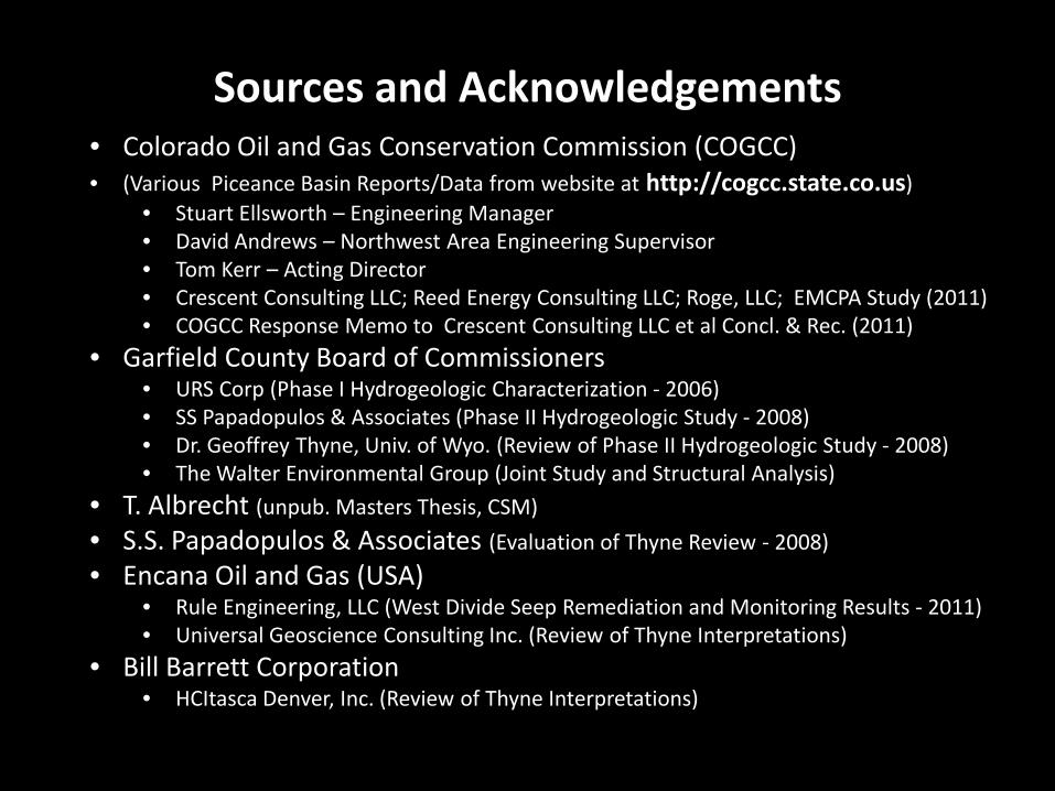
Sources and Acknowledgements • Colorado Oil and Gas Conservation Commission (COGCC) • (Various Piceance Basin Reports/Data from website at http://cogcc.state.co.us)
• Stuart Ellsworth – Engineering Manager • David Andrews – Northwest Area Engineering Supervisor • Tom Kerr – Acting Director • Crescent Consulting LLC; Reed Energy Consulting LLC; Roge, LLC; EMCPA Study (2011) • COGCC Response Memo to Crescent Consulting LLC et al Concl. & Rec. (2011)
• Garfield County Board of Commissioners • URS Corp (Phase I Hydrogeologic Characterization - 2006) • SS Papadopulos & Associates (Phase II Hydrogeologic Study - 2008) • Dr. Geoffrey Thyne, Univ. of Wyo. (Review of Phase II Hydrogeologic Study - 2008) • The Walter Environmental Group (Joint Study and Structural Analysis)
• T. Albrecht (unpub. Masters Thesis, CSM) • S.S. Papadopulos & Associates (Evaluation of Thyne Review - 2008) • Encana Oil and Gas (USA)
• Rule Engineering, LLC (West Divide Seep Remediation and Monitoring Results - 2011) • Universal Geoscience Consulting Inc. (Review of Thyne Interpretations)
• Bill Barrett Corporation • HCItasca Denver, Inc. (Review of Thyne Interpretations)
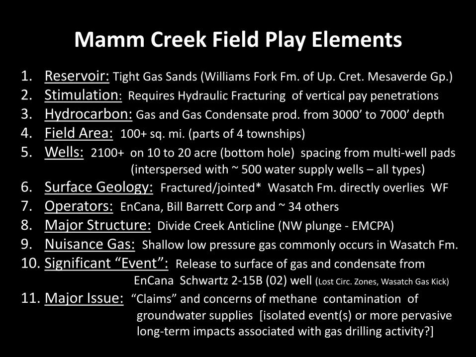
Mamm Creek Field Play Elements 1. Reservoir: Tight Gas Sands (Williams Fork Fm. of Up. Cret. Mesaverde Gp.) 2. Stimulation: Requires Hydraulic Fracturing of vertical pay penetrations 3. Hydrocarbon: Gas and Gas Condensate prod. from 3000’ to 7000’ depth 4. Field Area: 100+ sq. mi. (parts of 4 townships) 5. Wells: 2100+ on 10 to 20 acre (bottom hole) spacing from multi-well pads (interspersed with ~ 500 water supply wells – all types) 6. Surface Geology: Fractured/jointed* Wasatch Fm. directly overlies WF 7. Operators: EnCana, Bill Barrett Corp and ~ 34 others 8. Major Structure: Divide Creek Anticline (NW plunge - EMCPA) 9. Nuisance Gas: Shallow low pressure gas commonly occurs in Wasatch Fm. 10. Significant “Event”: Release to surface of gas and condensate from
EnCana Schwartz 2-15B (02) well (Lost Circ. Zones, Wasatch Gas Kick)
11. Major Issue: “Claims” and concerns of methane contamination of groundwater supplies [isolated event(s) or more pervasive long-term impacts associated with gas drilling activity?]
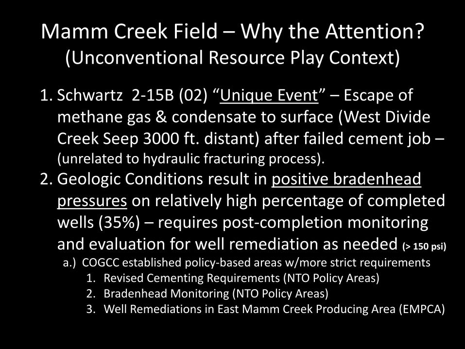
Mamm Creek Field – Why the Attention? (Unconventional Resource Play Context)
1. Schwartz 2-15B (02) “Unique Event” – Escape of methane gas & condensate to surface (West Divide Creek Seep 3000 ft. distant) after failed cement job – (unrelated to hydraulic fracturing process).
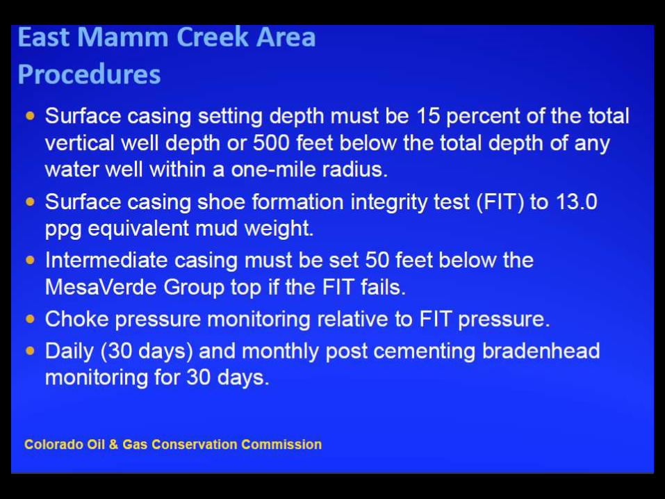
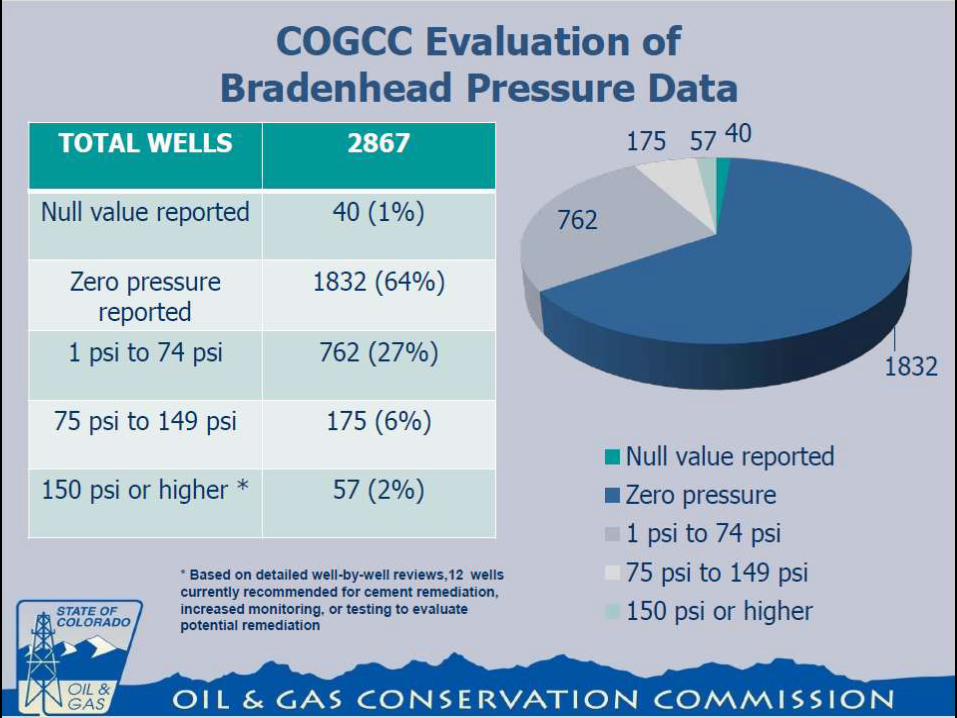
2. Geologic Conditions result in positive bradenhead pressures on relatively high percentage of completed wells (35%) – requires post-completion monitoring and evaluation for well remediation as needed (> 150 psi)
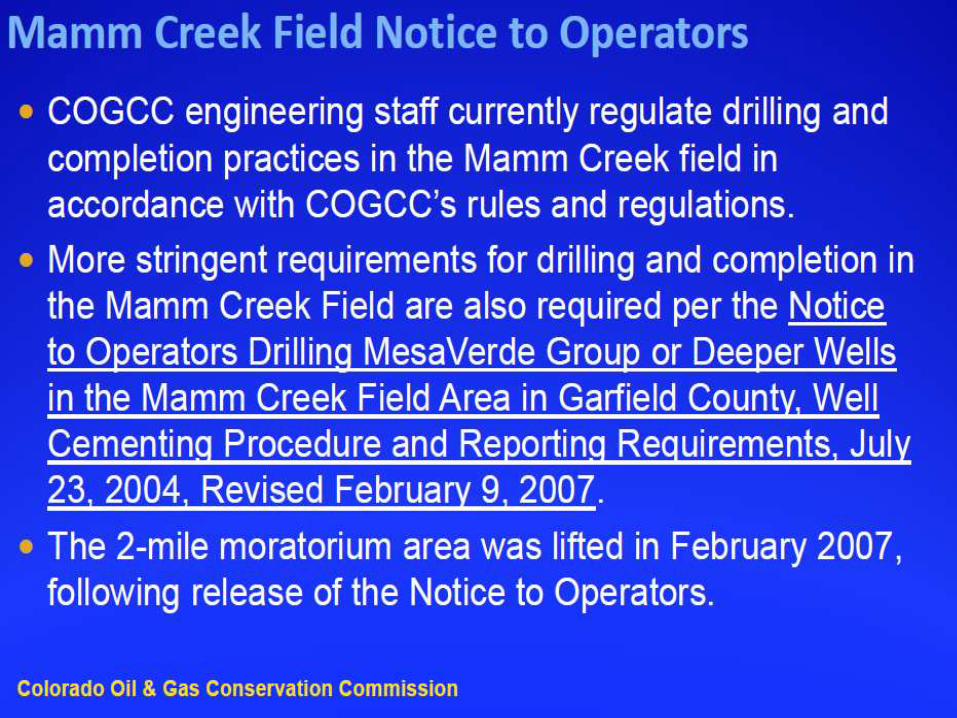
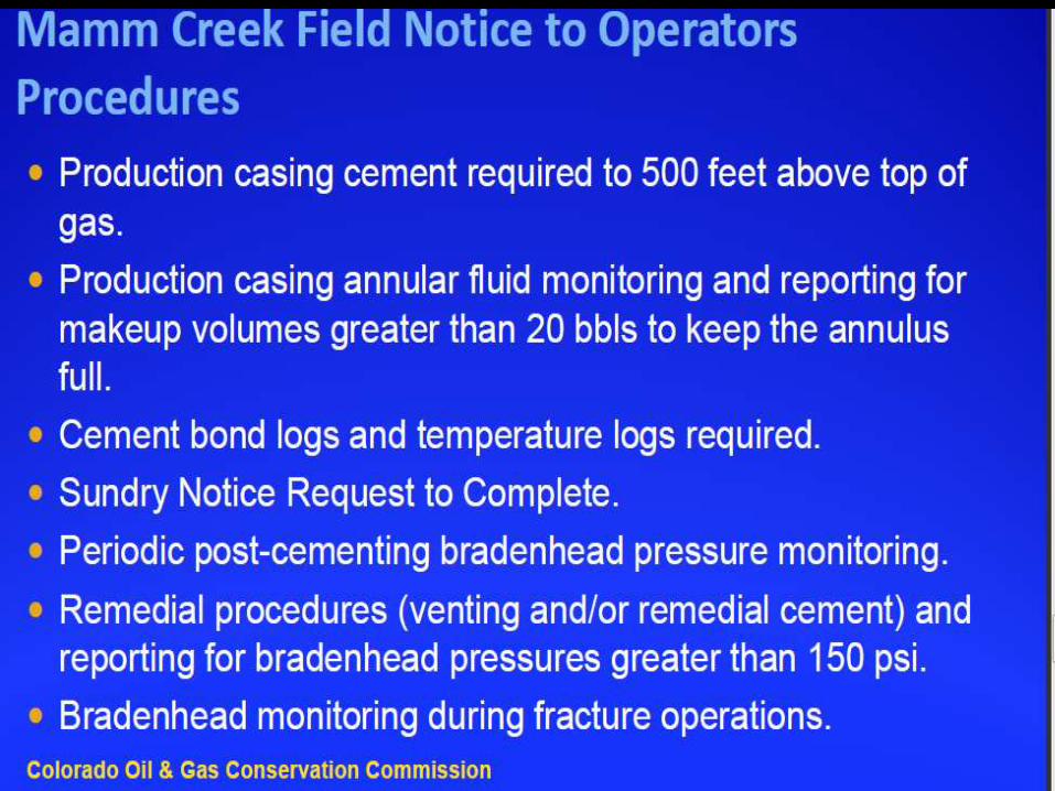
a.) COGCC established policy-based areas w/more strict requirements 1. Revised Cementing Requirements (NTO Policy Areas) 2. Bradenhead Monitoring (NTO Policy Areas) 3. Well Remediations in East Mamm Creek Producing Area (EMPCA)
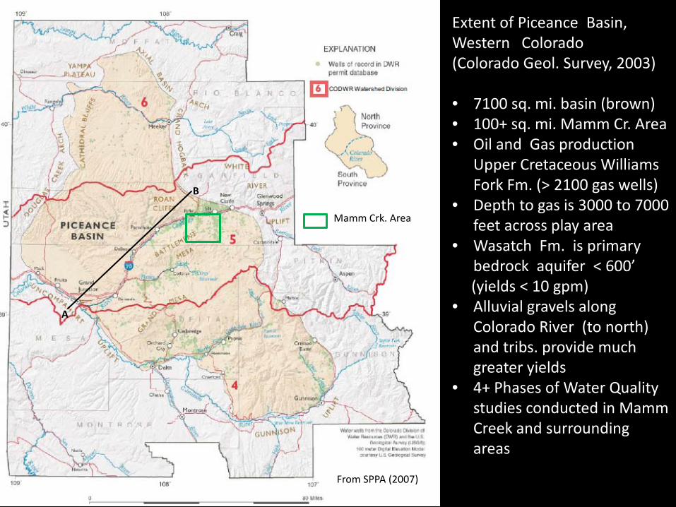
Extent of Piceance Basin, Western Colorado (Colorado Geol. Survey, 2003) • 7100 sq. mi. basin (brown) • 100+ sq. mi. Mamm Cr. Area • Oil and Gas production
Upper Cretaceous Williams Fork Fm. (> 2100 gas wells)
• Depth to gas is 3000 to 7000 feet across play area
• Wasatch Fm. is primary bedrock aquifer < 600’
(yields < 10 gpm) • Alluvial gravels along
Colorado River (to north) and tribs. provide much greater yields
• 4+ Phases of Water Quality studies conducted in Mamm Creek and surrounding areas
Mamm Crk. Area
From SPPA (2007)
A
B
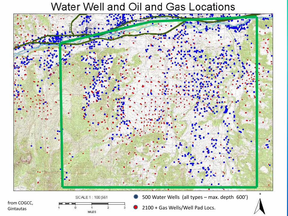
500 Water Wells (all types – max. depth 600’)
2100 + Gas Wells/Well Pad Locs. from COGCC, Gintautas
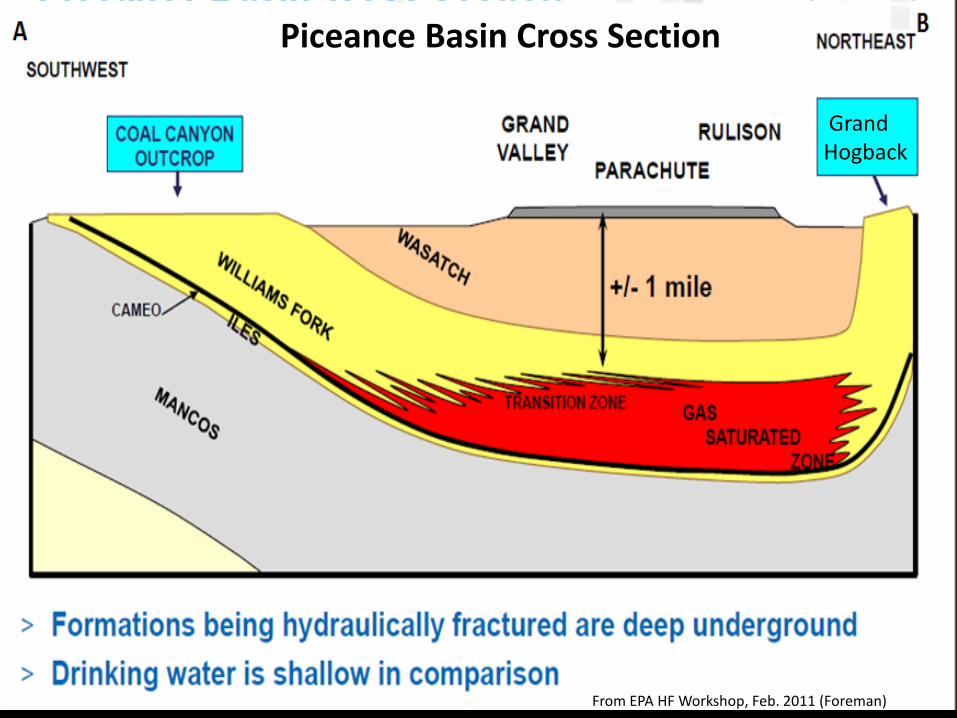
Piceance Basin Cross Section
From EPA HF Workshop, Feb. 2011 (Foreman)
Grand Hogback

Williams Fork Fm.
Fluvial & Floodplain dis-continuous sands/sand lenses –tight, highly “compartmentalized” sand reservoirs require small well spacings to exploit.
]
Geologic Section for Western Colorado Mamm Creek Area Geologic Section of Interest (red outline) Outcrop: Tertiary Wasatch Fm.
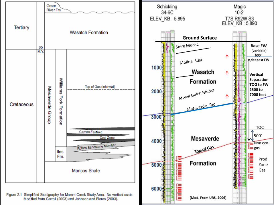
Ground Surface Base FW (variable) 600’ deepest FW
Vertical Separation TOG to FW 2500 to 7000 feet
(Mod. From URS, 2006)
Non eco. gas
Prod. Zone Gas
TOC
500’
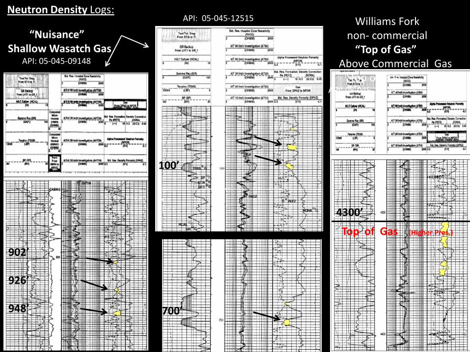
Williams Fork non- commercial “Top of Gas” Above Commercial Gas “Top of Gas” API: 05-045-12515
4300’
“Nuisance” Shallow Wasatch Gas API: 05-045-09148
902’
926’ 948’
100’
700’
API: 05-045-12515 Neutron Density Logs:
Top of Gas (Higher Pres.)

Piceance Basin Well Pad – Williams Fork Producing Wells
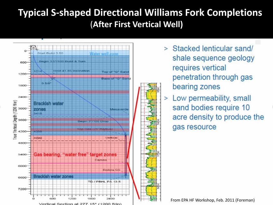
Typical S-shaped Directional Williams Fork Completions (After First Vertical Well)
From EPA HF Workshop, Feb. 2011 (Foreman))
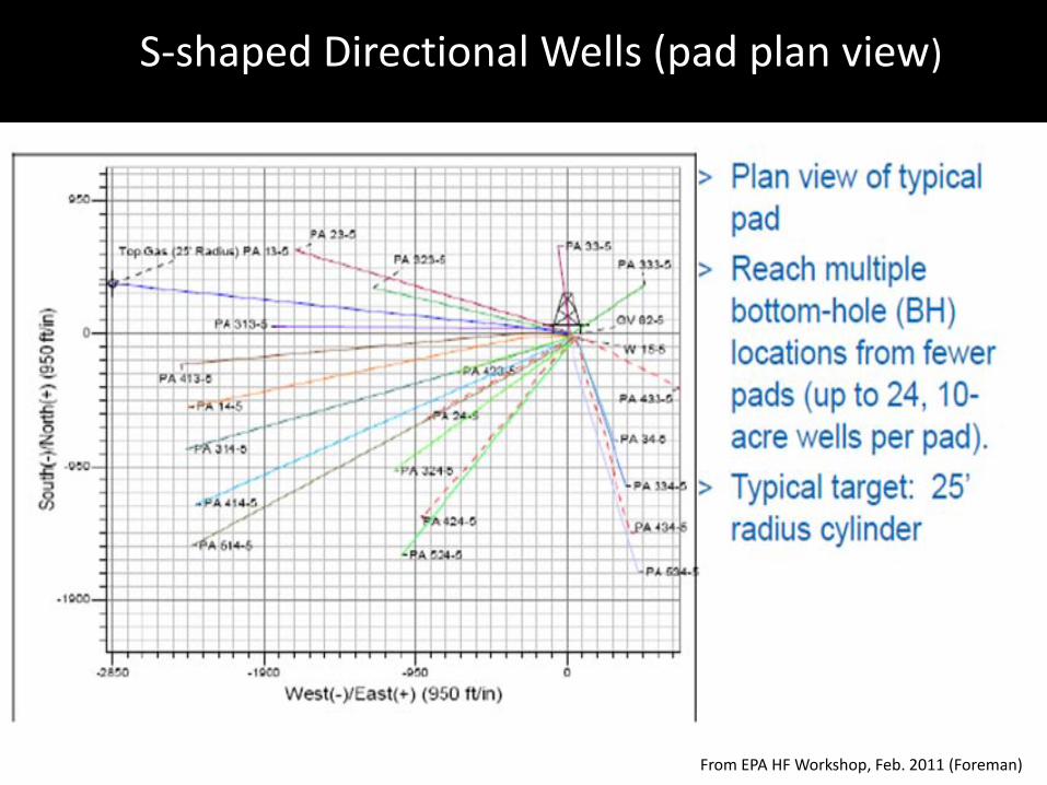
S-shaped Directional Wells (pad plan view)
From EPA HF Workshop, Feb. 2011 (Foreman)
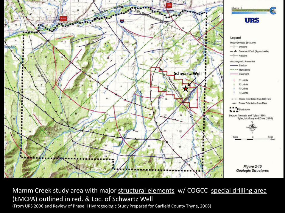
Mamm Creek study area with major structural elements w/ COGCC special drilling area (EMCPA) outlined in red. & Loc. of Schwartz Well (From URS 2006 and Review of Phase II Hydrogeologic Study Prepared for Garfield County Thyne, 2008)
Schwartz Well
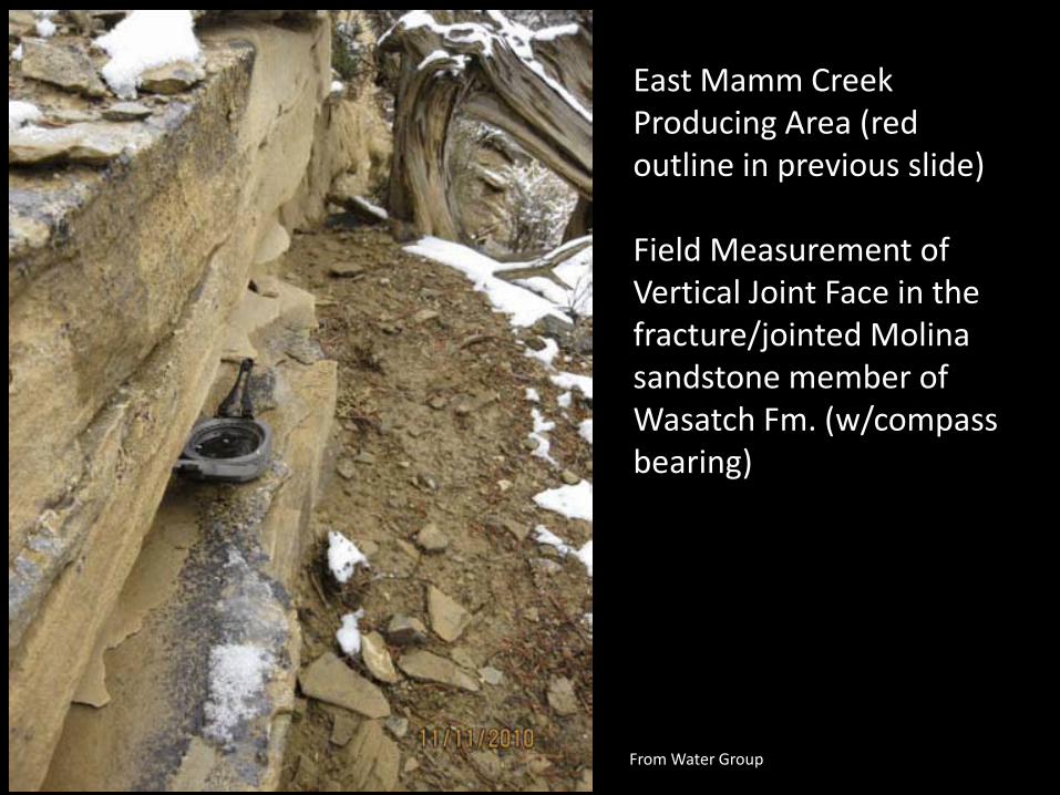
East Mamm Creek Producing Area (red outline in previous slide) Field Measurement of Vertical Joint Face in the fracture/jointed Molina sandstone member of Wasatch Fm. (w/compass bearing)
From Water Group

Photo of an exposed joint face in Molina (like) Sandstone north of the Arbaney(P3) well pad. (from Walter Group Report)
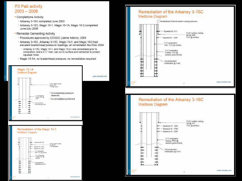
Sustained Elevated Bradenhead Pressures in 4 of P3 pad wells required pre-completion remediation. (COGCC)
Arbaney(P3) Well Pad
East Mamm Creek Prod./Policy Area (EMPCA)

N40E Joint
N105E Joint
Brunton
Joint sets in exposed surface sandstone outcrop of Molina (like) Sandstone Member of Wasatch Fm. (from Walter Group study)
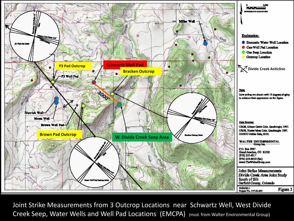
Joint Strike Measurements from 3 Outcrop Locations near Schwartz Well, West Divide Creek Seep, Water Wells and Well Pad Locations (EMCPA) (mod. from Walter Environmental Group)
W. Divide Creek Seep Area
Schwartz Well Pad P3 Pad Outcrop
Brown Pad Outcrop
Bracken Outcrop Divide Creek Anticline

Outline of Mamm Creek Producing Area (Black Outline Area, 2005) • 2100 + Gas Wells • ~ 66 + Domestic wells (of the 500 WSW)
Locations of Domestic Wtr. Supply Wells
From URS 2005
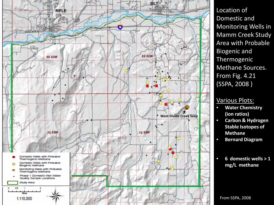
Location of Domestic and Monitoring Wells in Mamm Creek Study Area with Probable Biogenic and Thermogenic Methane Sources. From Fig. 4.21 (SSPA, 2008 ) Various Plots: • Water Chemistry
(ion ratios) • Carbon & Hydrogen
Stable Isotopes of Methane
• Bernard Diagram
• 6 domestic wells > 1 mg/L methane
West Divide Creek Seep
From SSPA, 2008
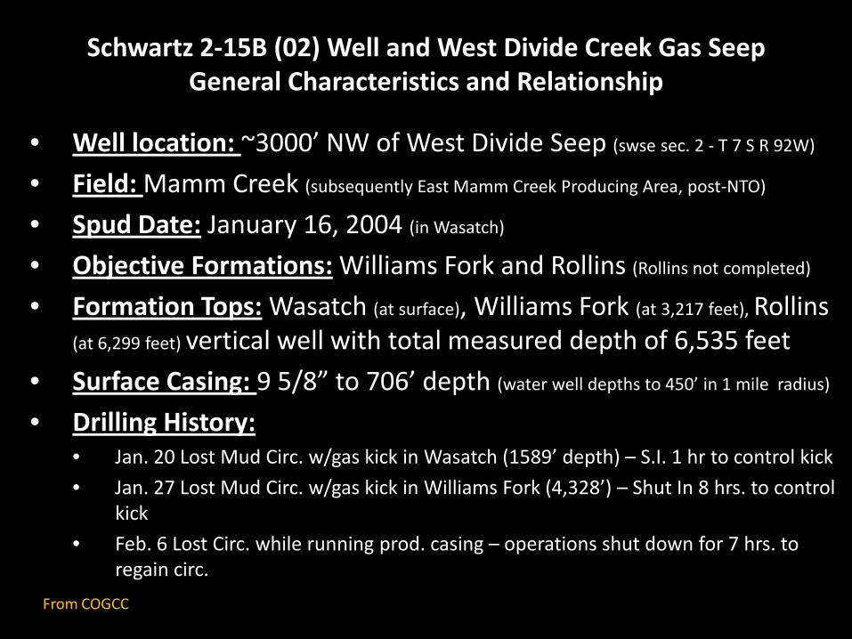
Schwartz 2-15B (02) Well and West Divide Creek Gas Seep General Characteristics and Relationship
• Well location: ~3000’ NW of West Divide Seep (swse sec. 2 - T 7 S R 92W)
• Field: Mamm Creek (subsequently East Mamm Creek Producing Area, post-NTO)
• Spud Date: January 16, 2004 (in Wasatch)
• Objective Formations: Williams Fork and Rollins (Rollins not completed)
• Formation Tops: Wasatch (at surface), Williams Fork (at 3,217 feet), Rollins
(at 6,299 feet) vertical well with total measured depth of 6,535 feet • Surface Casing: 9 5/8” to 706’ depth (water well depths to 450’ in 1 mile radius)
• Drilling History: • Jan. 20 Lost Mud Circ. w/gas kick in Wasatch (1589’ depth) – S.I. 1 hr to control kick • Jan. 27 Lost Mud Circ. w/gas kick in Williams Fork (4,328’) – Shut In 8 hrs. to control
kick • Feb. 6 Lost Circ. while running prod. casing – operations shut down for 7 hrs. to
regain circ.
From COGCC
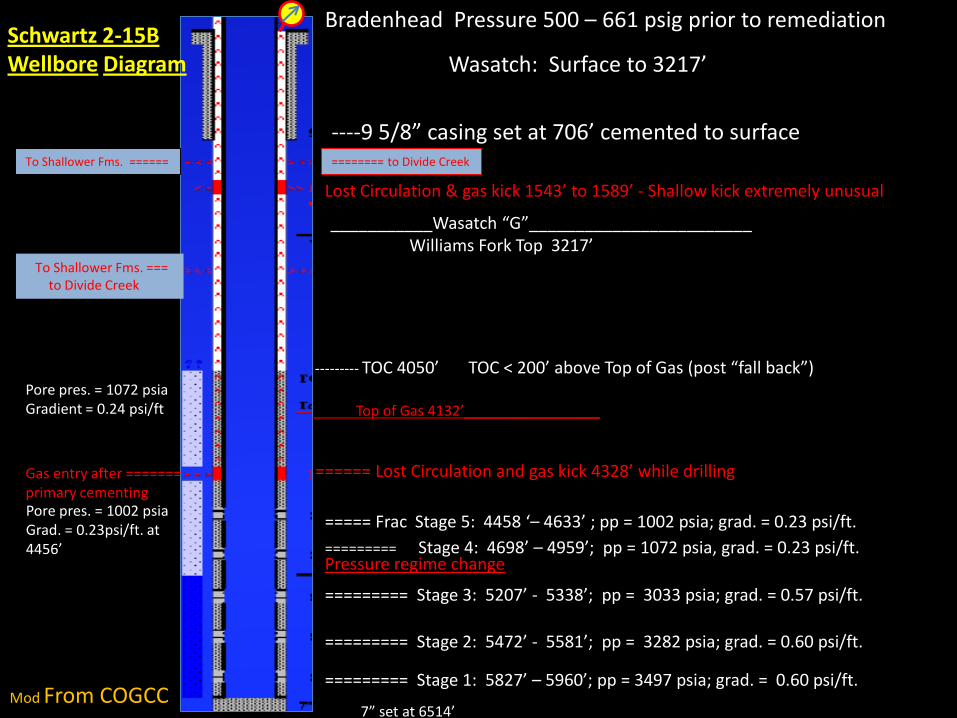
Schwartz 2-15B Wellbore Diagram
Bradenhead Pressure 500 – 661 psig prior to remediation
Wasatch: Surface to 3217’
----9 5/8” casing set at 706’ cemented to surface To Shallower Fms. ====== ======== to Divide Creek
Lost Circulation & gas kick 1543’ to 1589’ - Shallow kick extremely unusual
___________Wasatch “G”________________________ Williams Fork Top 3217’ To Shallower Fms. ===
to Divide Creek
Pore pres. = 1072 psia Gradient = 0.24 psi/ft
--------- TOC 4050’ TOC < 200’ above Top of Gas (post “fall back”) Top of Gas 4132’_________________
====== Lost Circulation and gas kick 4328’ while drilling Gas entry after ======= primary cementing Pore pres. = 1002 psia Grad. = 0.23psi/ft. at 4456’
===== Frac Stage 5: 4458 ‘– 4633’ ; pp = 1002 psia; grad. = 0.23 psi/ft. ========= Stage 4: 4698’ – 4959’; pp = 1072 psia, grad. = 0.23 psi/ft. Pressure regime change
========= Stage 3: 5207’ - 5338’; pp = 3033 psia; grad. = 0.57 psi/ft. ========= Stage 2: 5472’ - 5581’; pp = 3282 psia; grad. = 0.60 psi/ft. ========= Stage 1: 5827’ – 5960’; pp = 3497 psia; grad. = 0.60 psi/ft.
7” set at 6514’ Mod From COGCC

Con’t. Schwartz well history • Production Casing Primary Cement Job:
• Cement initially circulated to surface (25 bbls) • Feb. 16,- CBL run shows TOC fallen to 4,050 depth (top of gas at 4,132’ in WF - only 82 feet
separation: TOC to TOG) -Temp. survey indicated upward gas migration under Shut-In cond. (cooling at 4,328’)
• Completion and Post-Completion Bradenhead Pressure Measurements:
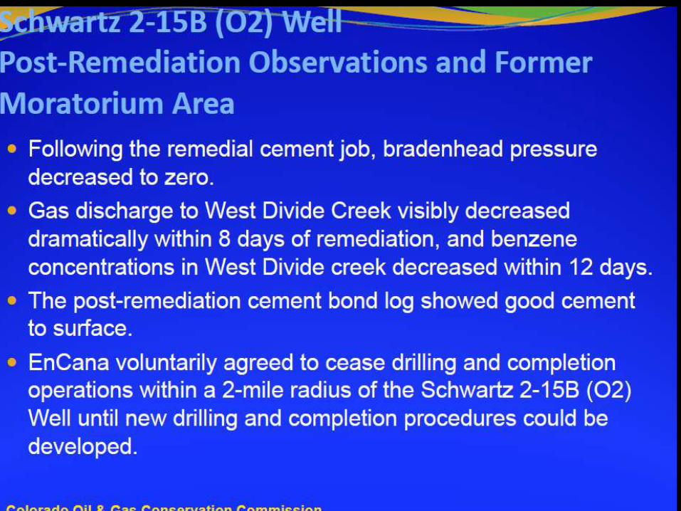
• EnCana proceeded with frac stimulation of well through March • Final frac stage (5) at 4,458’ to 4,633, No BH pres. build-up during frac but build up after frack • EnCana also observes BH pres. (515-650 psi) following completion activities and prior to
remedial cement operations • EnCana submits Sundry Notice to COGCC on Mar. 23 (for remedial cement ops.) • COGCC approves Sundry Notice on Mar. 30 • April 1 - report of Gas Seep in West Divide Creek 3000’ away • During Apr. 4 remedial cement job, flowing BH pres. range 500 to 650 psi • Gas sample analytical results (isotopic & compositional) → Williams Fork gas is origin
• Same for other nearby wells BH gas • BH pressure drops to 0 psi after Remedial Cement Job and gas flow to creek subsides
dramatically w/in 8 days - Benzene levels in Creek drop after 12 days • EnCana agrees to 2 mile drilling moratorium while problems are investigated further • East Mamm Creek Production Policy area NTO established (revised drilling and
completion/cementing ) • Gas sampling (isotopic & compositional analysis) indicates Bradenhead gas is from Williams
Fork (including other nearby wells)
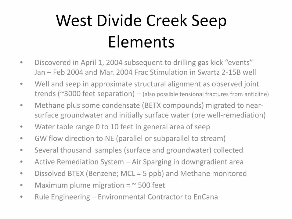
West Divide Creek Seep Elements
• Discovered in April 1, 2004 subsequent to drilling gas kick “events” Jan – Feb 2004 and Mar. 2004 Frac Stimulation in Swartz 2-15B well
• Well and seep in approximate structural alignment as observed joint trends (~3000 feet separation) – (also possible tensional fractures from anticline)
• Methane plus some condensate (BETX compounds) migrated to near-surface groundwater and initially surface water (pre well-remediation)
• Water table range 0 to 10 feet in general area of seep • GW flow direction to NE (parallel or subparallel to stream) • Several thousand samples (surface and groundwater) collected • Active Remediation System – Air Sparging in downgradient area • Dissolved BTEX (Benzene; MCL = 5 ppb) and Methane monitored • Maximum plume migration = ~ 500 feet • Rule Engineering – Environmental Contractor to EnCana
Benzene Concentration
Methane Concentration
GW Flow
Air Sparge Wells
West Divide Crk. Seep (near MW-14)
West Divide Crk. Seep (near MW-14)

Arrows show up gradient to down gradient well transition
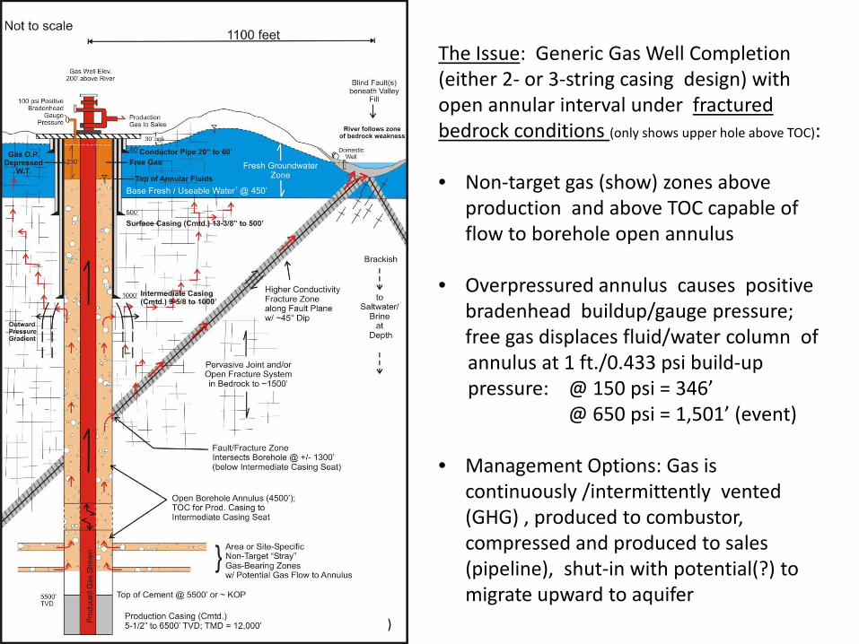
The Issue: Generic Gas Well Completion (either 2- or 3-string casing design) with open annular interval under fractured bedrock conditions (only shows upper hole above TOC):
• Non-target gas (show) zones above
production and above TOC capable of flow to borehole open annulus
• Overpressured annulus causes positive
bradenhead buildup/gauge pressure; free gas displaces fluid/water column of
annulus at 1 ft./0.433 psi build-up pressure: @ 150 psi = 346’ @ 650 psi = 1,501’ (event)
• Management Options: Gas is
continuously /intermittently vented (GHG) , produced to combustor, compressed and produced to sales (pipeline), shut-in with potential(?) to migrate upward to aquifer
( From Penoyer, 2011))

Summary & Conclusions • Schwartz well gas and condensate escape to surface (Divide
Creek Seep) • Unique “event” caused by failure of the primary cement job (~4000’ “fall
back”) left insufficient TOG to TOC separation • “Event” was unrelated to the underground hydraulic fracturing “process”
itself • Overpressure of open annular interval by Williams Fork gas resulted in
effectively an underground blow out with well shut in for several days • Gas escaped via pathway of fractured (fault?) or jointed bedrock that
intersected borehole wall below surface casing seat to circumvent surface casing & cement of good integrity (problematic well design issue when lost circulation zones compromise circulation of production casing cement to surface)
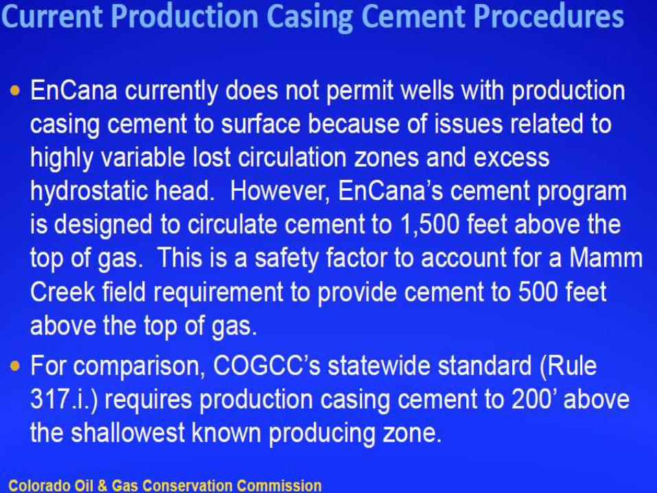
• Current production casing cement jobs are designed to isolate all gas producing zones in the Williams Fork Fm. (NTO’s, APD’s w/COA’s) with the requirement of higher TOC but still leaving some open annular for monitoring purposes

CONCLUSIONS con’t.
• Nuisance gas management from the Wasatch Fm. (low vol.,
low pressure. , non-economic.) • “Nuisance” gas in the Wasatch Fm. is an independent issue in the greater
Mamm Creek area that leads to positive bradenhead pressures on a significant percentage of wells
• Bradenhead monitoring and venting is effective mitigation method for potential impacts (evaluate wells for remediation > 150 psi) but it is unclear to what degree any sustained pressure poses a threat of methane migration to drinking water aquifers/supplies over the long term should an open fracture system intersect the open annular borehole wall
• Attempts to circulate cement across Wasatch zones are only “marginally effective” at limiting bradenhead build-up pressures
• COGCC explores isolation of such zones on a well-by-well basis based on several factors and sustained elevated bradenhead pressures may require targeted cement remediation
• Historic venting of bradenhead methane as a future management option needs further analysis given the un-quantified volumes and Global Warming Potential (GWP) of this GHC

T H A N K Y O U
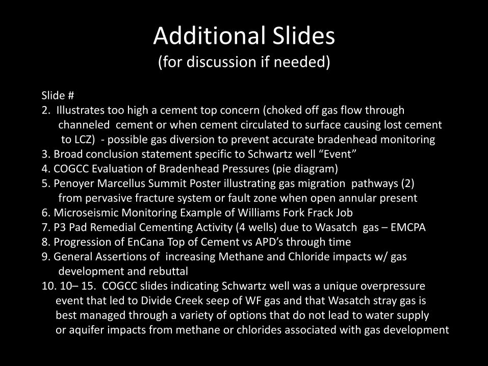
Additional Slides (for discussion if needed)
Slide # 2. Illustrates too high a cement top concern (choked off gas flow through channeled cement or when cement circulated to surface causing lost cement to LCZ) - possible gas diversion to prevent accurate bradenhead monitoring 3. Broad conclusion statement specific to Schwartz well “Event” 4. COGCC Evaluation of Bradenhead Pressures (pie diagram) 5. Penoyer Marcellus Summit Poster illustrating gas migration pathways (2) from pervasive fracture system or fault zone when open annular present 6. Microseismic Monitoring Example of Williams Fork Frack Job 7. P3 Pad Remedial Cementing Activity (4 wells) due to Wasatch gas – EMCPA 8. Progression of EnCana Top of Cement vs APD’s through time 9. General Assertions of increasing Methane and Chloride impacts w/ gas development and rebuttal 10. 10– 15. COGCC slides indicating Schwartz well was a unique overpressure event that led to Divide Creek seep of WF gas and that Wasatch stray gas is best managed through a variety of options that do not lead to water supply or aquifer impacts from methane or chlorides associated with gas development
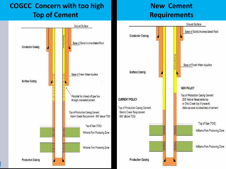
COGCC Concern with too high Top of Cement
New Cement Requirements
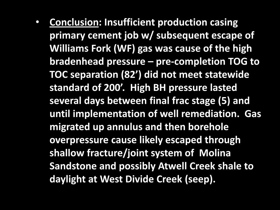
• Conclusion: Insufficient production casing primary cement job w/ subsequent escape of Williams Fork (WF) gas was cause of the high bradenhead pressure – pre-completion TOG to TOC separation (82’) did not meet statewide standard of 200’. High BH pressure lasted several days between final frac stage (5) and until implementation of well remediation. Gas migrated up annulus and then borehole overpressure cause likely escaped through shallow fracture/joint system of Molina Sandstone and possibly Atwell Creek shale to daylight at West Divide Creek (seep).
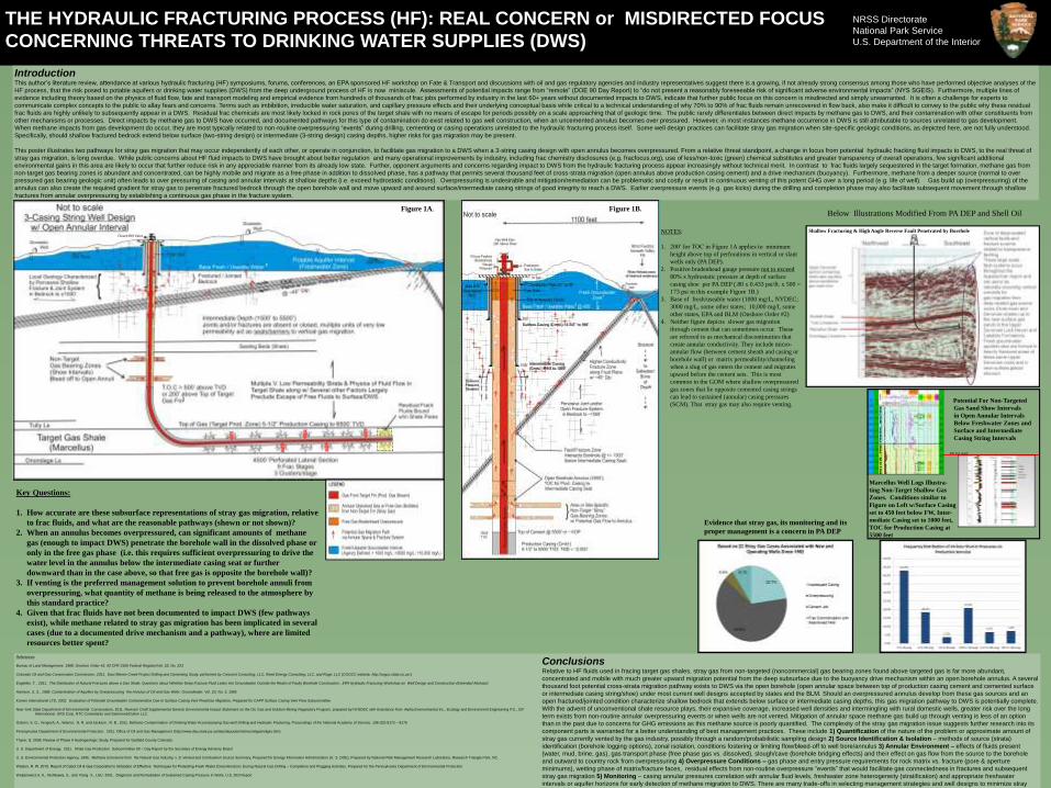
THE HYDRAULIC FRACTURING PROCESS (HF): REAL CONCERN or MISDIRECTED FOCUS
CONCERNING THREATS TO DRINKING WATER SUPPLIES (DWS)
IntroductionThis author’s literature review, attendance at various hydraulic fracturing (HF) symposiums, forums, conferences, an EPA sponsored HF workshop on Fate & Transport and discussions with oil and gas regulatory agencies and industry representatives suggest there is a growing, if not already strong consensus among those who have performed objective analyses of the HF process, that the risk posed to potable aquifers or drinking water supplies (DWS) from the deep underground process of HF is now miniscule. Assessments of potential impacts range from “remote” (DOE 90 Day Report) to “do not present a reasonably foreseeable risk of significant adverse environmental impacts” (NYS SGEIS). Furthermore, multiple lines of
evidence including theory based on the physics of fluid flow, fate and transport modeling and empirical evidence from hundreds of thousands of frac jobs performed by industry in the last 60+ years without documented impacts to DWS, indicate that further public focus on this concern is misdirected and simply unwarranted. It is often a challenge for experts to communicate complex concepts to the public to allay fears and concerns. Terms such as imbibition, irreducible water saturation, and capillary pressure effects and their underlying conceptual basis while critical to a technical understanding of why 70% to 90% of frac fluids remain unrecovered in flow back, also make it difficult to convey to the public why these residual frac fluids are highly unlikely to subsequently appear in a DWS. Residual frac chemicals are most likely locked in rock pores of the target shale with no means of escape for periods possibly on a scale approaching that of geologic time. The public rarely differentiates between direct impacts by methane gas to DWS, and their contamination with other constituents from other mechanisms or processes. Direct impacts by methane gas to DWS have occurred, and documented pathways for this type of contamination do exist related to gas well construction, when an uncemented annulus becomes over pressured. However, in most instances methane occurrence in DWS is still attributable to sources unrelated to gas development. When methane impacts from gas development do occur, they are most typically related to non-routine overpressuring “events” during drilling, cementing or casing operations unrelated to the hydraulic fracturing process itself. Some well design practices can facilitate stray gas migration when site-specific geologic conditions, as depicted here, are not fully understood. Specifically, should shallow fractured bedrock extend below surface (two-string design) or intermediate (3-string design) casing depths, higher risks for gas migration may be present.
This poster illustrates two pathways for stray gas migration that may occur independently of each other, or operate in conjunction, to facilitate gas migration to a DWS when a 3-string casing design with open annulus becomes overpressured. From a relative threat standpoint, a change in focus from potential hydraulic fracking fluid impacts to DWS, to the real threat of stray gas migration, is long overdue. While public concerns about HF fluid impacts to DWS have brought about better regulation and many operational improvements by industry, including frac chemistry disclosures (e.g. fracfocus.org), use of less/non-toxic (green) chemical substitutes and greater transparency of overall operations, few significant additional environmental gains in this area are likely to occur that further reduce risk in any appreciable manner from its already low state. Further, opponent arguments and concerns regarding impact to DWS from the hydraulic fracturing process appear increasingly without technical merit. In contrast to frac fluids largely sequestered in the target formation, methane gas from non-target gas bearing zones is abundant and concentrated, can be highly mobile and migrate as a free phase in addition to dissolved phase, has a pathway that permits several thousand feet of cross-strata migration (open annulus above production casing cement) and a drive mechanism (buoyancy). Furthermore, methane from a deeper source (normal to over pressured gas bearing geologic unit) often leads to over pressuring of casing and annular intervals at shallow depths (i.e. exceed hydrostatic conditions). Overpressuring is undesirable and mitigation/remediation can be problematic and costly or result in continuous venting of this potent GHG over a long period (e.g. life of well). Gas build up (overpressuring) of the annulus can also create the required gradient for stray gas to penetrate fractured bedrock through the open borehole wall and move upward and around surface/intermediate casing strings of good integrity to reach a DWS. Earlier overpressure events (e.g. gas kicks) during the drilling and completion phase may also facilitate subsequent movement through shallow fractures from annular overpressuring by establishing a continuous gas phase in the fracture system.
ConclusionsRelative to HF fluids used in fracing target gas shales, stray gas from non-targeted (noncommercial) gas bearing zones found above targeted gas is far more abundant, concentrated and mobile with much greater upward migration potential from the deep subsurface due to the buoyancy drive mechanism within an open borehole annulus. A several thousand foot potential cross-strata migration pathway exists to DWS via the open borehole (open annular space between top of production casing cement and cemented surface or intermediate casing string/shoe) under most current well designs accepted by states and the BLM. Should an overpressured annulus develop from these gas sources and an open fractured/jointed condition characterize shallow bedrock that extends below surface or intermediate casing depths, this gas migration pathway to DWS is potentially complete. With the advent of unconventional shale resource plays, their expansive coverage, increased well densities and intermingling with rural domestic wells, greater risk over the long term exists from non-routine annular overpressuring events or when wells are not vented. Mitigation of annular space methane gas build up through venting is less of an option than in the past due to concerns for GHG emissions as this methane source is poorly quantified. The complexity of the stray gas migration issue suggests further research into its component parts is warranted for a better understanding of best management practices. These include 1) Quantification of the nature of the problem or approximate amount of stray gas currently vented by the gas industry, possibly through a random/probabilistic sampling design 2) Source Identification & Isolation – methods of source (strata) identification (borehole logging options), zonal isolation, conditions fostering or limiting flow/bleed-off to well bore/annulus 3) Annular Environment – effects of fluids present (water, mud, brine, gas), gas transport phase (free phase gas vs. dissolved), slough/cave (borehole bridging effects) and their effect on gas flow from the source to the borehole and outward to country rock from overpressuring 4) Overpressure Conditions – gas phase and entry pressure requirements for rock matrix vs. fracture (pore & aperture minimums), wetting phase of matrix/fracture faces, residual effects from non-routine overpressure “events” that would facilitate gas connectedness in fractures and subsequent
stray gas migration 5) Monitoring – casing annular pressures correlation with annular fluid levels, freshwater zone heterogeneity (stratification) and appropriate freshwater intervals or aquifer horizons for early detection of methane migration to DWS. There are many trade-offs in selecting management strategies and well designs to minimize stray gas. Further analysis of the components is warranted to better assess cost-benefit relationships and to ensure that GHG emissions and potential impacts to DWS are minimized.
References
Bureau of Land Management, 1988. Onshore Order #2, 43 CFR 3160 Federal Register/Vol. 53, No. 223
Colorado Oil and Gas Conservation Commission, 2011. East Mamm Creek Project Drilling and Cementing Study, performed by Crescent Consulting, LLC, Reed Energy Consulting, LLC, and Roge, LLC (COGCC website, http://cogcc.state.co.us/.)
Engelder, T. , 2011. The Distribution of Natural Fractures above a Gas Shale: Questions about Whether Deep Fracture Fluid Leaks into Groundwater Outside the Realm of Faulty Borehole Construction , EPA Hydraulic Fracturing Workshop on Well Design and Construction (Extended Abstract)
Harrison, S. S., 1985. Contamination of Aquifers by Overpressuring the Annulus of Oil and Gas Wells Groundwater, Vol. 23, No. 3, 1985
Komex International LTD, 2002. Evaluation of Potential Groundwater Contamination Due to Surface Casing Vent Flow/Gas Migration, Prepared for CAPP Surface Casing Vent Flow Subcommittee
New York State Department of Environmental Conservation, 2011. Revised Draft Supplemental Generic Environmental Impact Statement on the Oil, Gas and Solution Mining Regulatory Program, prepared by NYSDEC with Assistance from Alpha Environmental Inc., Ecology and Environment Engineering P.C., ICF International, URS Corp, NTC Consultants and Sammons/Dutton LLC.
Osborn, S. G., Vengosh, A., Warner, N. R. and Jackson , R. B., 2011, Methane Contamination of Drinking Water Accompanying Gas-well Drilling and Hydraulic Fracturing, Proceedings of the National Academy of Science, 108 (20) 8172 – 8176
Pennsylvania Department of Environmental Protection, 2011. Office of Oil and Gas Management (http://www.dep.state.pa.us/dep/deputate/minres/oilgas/oilgas.htm)
Thyne, G. 2008. Review of Phase II Hydrogeologic Study, Prepared for Garfield County Colorado.
U. S. Department of Energy, 2011. Shale Gas Production Subcommittee 90 – Day Report by the Secretary of Energy Advisory Board
U. S. Environmental Protection Agency, 1996. Methane Emissions from the Natural Gas Industry, v. 9; Vented and Combustion Source Summary, Prepared for Energy Information Administration (U. S. DOE), Prepared by National Risk Management Research Laboratory, Research Triangle Park, NC.
Watson, R. W. 2010. Report of Cabot Oil & Gas Corporation’s Utilization of Effective Techniques for Protecting Fresh Water Zones/Horizons During Natural Gas Drilling – Completion and Plugging Activities, Prepared for the Pennsylvania Department of Environmental Protection
Wojtanowicz A. K., Nishikawa, S., and Rong X., LSU 2001. Diagnosis and Remediation of Sustained Casing Pressure in Wells, U.S. DOI Report
NRSS DirectorateNational Park ServiceU.S. Department of the Interior
Pete Penoyer Hydrogeologist Natural Resource Stewardship & Science [email protected]
Acknowledgements:
PA DEP Staff for their availability , consultation and review to ensure illustrations are as accurate as possible
I also wish to thank the following NPS Staff for their assistance with this poster presentation
Paula Cutillo , WRD Hydrogeologist - Graphics Design & Presentation
400 foot depth
Below Illustrations Modified From PA DEP and Shell Oil
Closed BH Valve
Shallow Fracturing & High Angle Reverse Fault Penetrated by Borehole
Evidence that stray gas, its monitoring and its
proper management is a concern in PA DEP
Key Questions:
1. How accurate are these subsurface representations of stray gas migration, relative
to frac fluids, and what are the reasonable pathways (shown or not shown)?
2. When an annulus becomes overpressured, can significant amounts of methane
gas (enough to impact DWS) penetrate the borehole wall in the dissolved phase or
only in the free gas phase (i.e. this requires sufficient overpressuring to drive the
water level in the annulus below the intermediate casing seat or further
downward than in the case above, so that free gas is opposite the borehole wall)?
3. If venting is the preferred management solution to prevent borehole annuli from
overpressuring, what quantity of methane is being released to the atmosphere by
this standard practice?
4. Given that frac fluids have not been documented to impact DWS (few pathways
exist), while methane related to stray gas migration has been implicated in several
cases (due to a documented drive mechanism and a pathway), where are limited
resources better spent?
1
NOTES:
1. 200’ for TOC in Figure 1A applies to minimum
height above top of perforations in vertical or slant
wells only (PA DEP).
2. Positive bradenhead gauge pressure not to exceed
80% x hydrostatic pressure at depth of surface
casing shoe per PA DEP (.80 x 0.433 psi/ft. x 500 =
173 psi in this example Figure 1B.)
3. Base of fresh/useable water (1000 mg/L, NYDEC;
3000 mg/L, some other states; 10,000 mg/L some
other states, EPA and BLM (Onshore Order #2)
4. Neither figure depicts slower gas migration
through cement that can sometimes occur. These
are referred to as mechanical discontinuities that
create annular conductivity. They include micro-
annular flow (between cement sheath and casing or
borehole wall) or matrix permeability/channeling
when a slug of gas enters the cement and migrates
upward before the cement sets. This is most
common in the GOM where shallow overpressured
gas zones that lie opposite cemented casing strings
can lead to sustained (annular) casing pressures
(SCM). That stray gas may also require venting.
Figure 1A. Figure 1B.
3
Potential For Non-Targeted
Gas Sand Show Intervals
in Open Annular Intervals
Below Freshwater Zones and
Surface and Intermediate
Casing String Intervals
Marcellus Well Logs Illustra-
ting Non-Target Shallow Gas
Zones. Conditions similar to
Figure on Left w/Surface Casing
set to 450 feet below FW, Inter-
mediate Casing set to 1000 feet,
TOC for Production Casing at
5500 feet
400 foot depth
3
3
Disclaimer: This poster is of an interpretive nature and reflects the author’s assimilation of the
published work of many researchers and information from discussions with regulatory agency
staff. Its purpose is to foster informed discussion of the potential impacts from stray gas
migration to drinking water supplies in the context of unconventional resource plays.
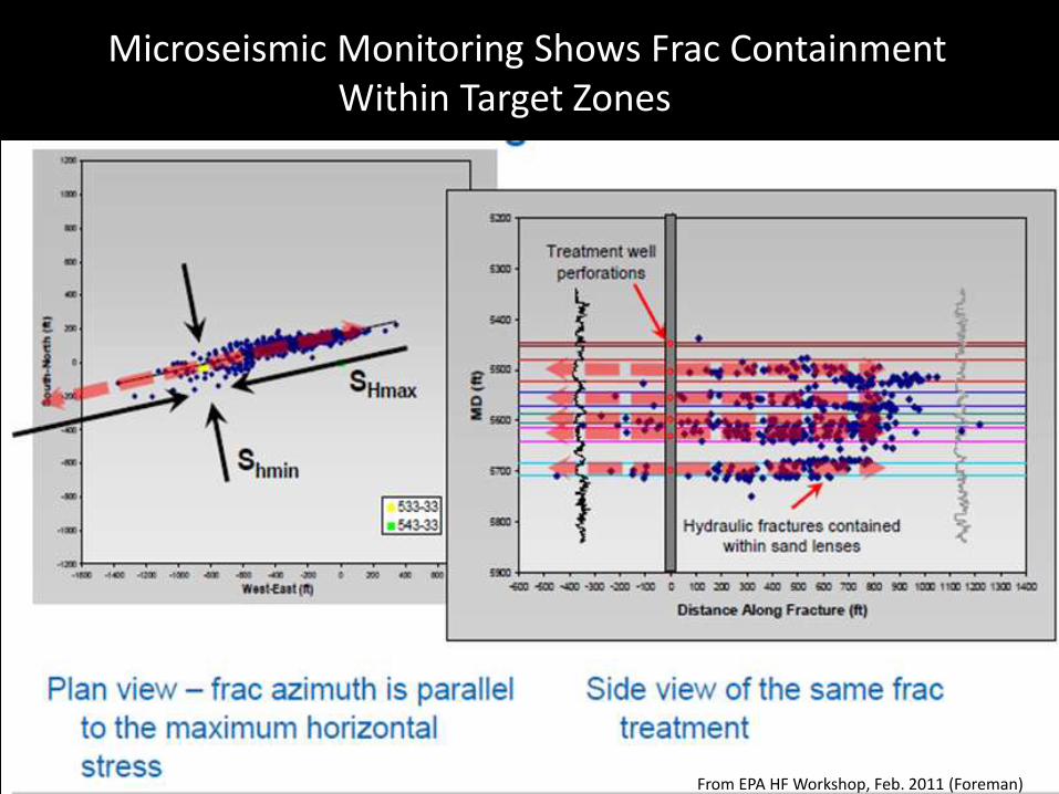
Microseismic Monitoring Shows Frac Containment Within Target Zones
From EPA HF Workshop, Feb. 2011 (Foreman)

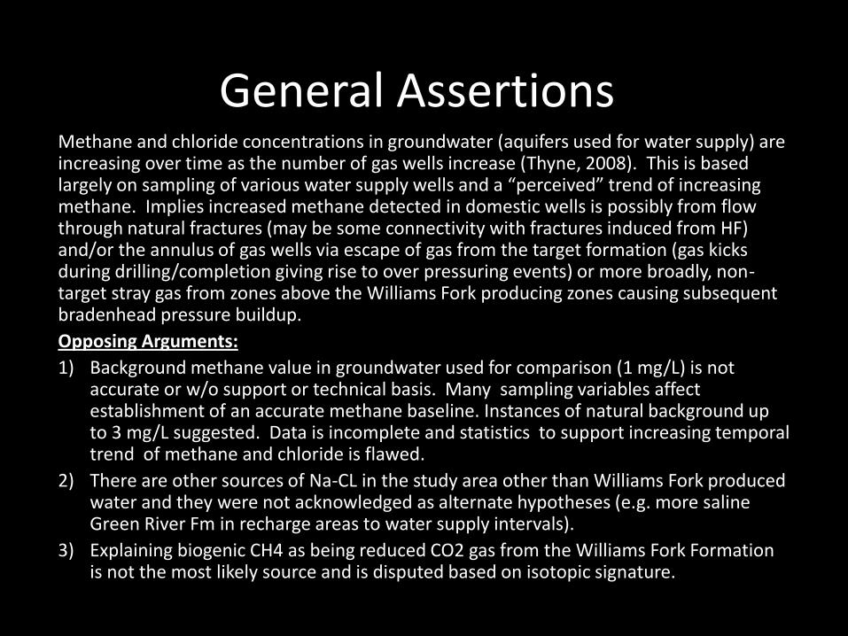
General Assertions Methane and chloride concentrations in groundwater (aquifers used for water supply) are increasing over time as the number of gas wells increase (Thyne, 2008). This is based largely on sampling of various water supply wells and a “perceived” trend of increasing methane. Implies increased methane detected in domestic wells is possibly from flow through natural fractures (may be some connectivity with fractures induced from HF) and/or the annulus of gas wells via escape of gas from the target formation (gas kicks during drilling/completion giving rise to over pressuring events) or more broadly, non-target stray gas from zones above the Williams Fork producing zones causing subsequent bradenhead pressure buildup.
Opposing Arguments:
1) Background methane value in groundwater used for comparison (1 mg/L) is not accurate or w/o support or technical basis. Many sampling variables affect establishment of an accurate methane baseline. Instances of natural background up to 3 mg/L suggested. Data is incomplete and statistics to support increasing temporal trend of methane and chloride is flawed.
2) There are other sources of Na-CL in the study area other than Williams Fork produced water and they were not acknowledged as alternate hypotheses (e.g. more saline Green River Fm in recharge areas to water supply intervals).
3) Explaining biogenic CH4 as being reduced CO2 gas from the Williams Fork Formation is not the most likely source and is disputed based on isotopic signature.