Embed Size (px)
Citation preview
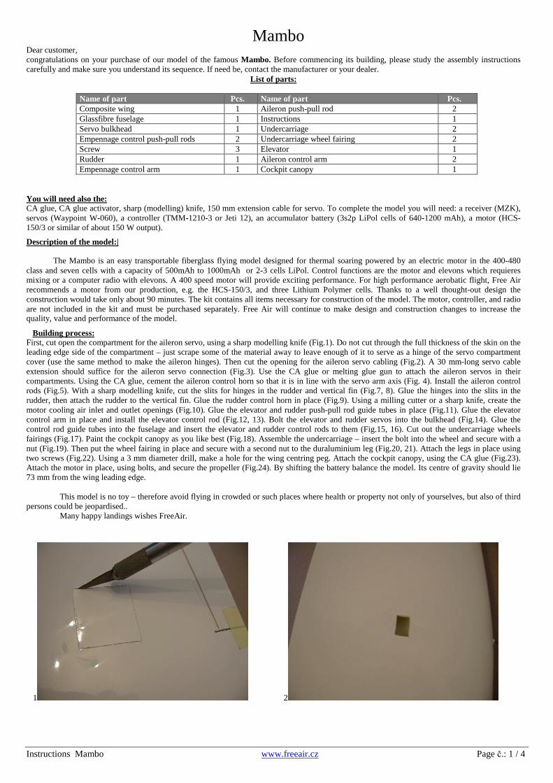
Mambo
Instructions Mambo www.freeair.cz Page č.: 1 / 4
Dear customer,congratulations on your purchase of our model of the famous Mambo. Before commencing its building, please study the assembly instructionscarefully and make sure you understand its sequence. If need be, contact the manufacturer or your dealer.
List of parts:
Name of part Pcs. Name of part Pcs.Composite wing 1 Aileron push-pull rod 2Glassfibre fuselage 1 Instructions 1Servo bulkhead 1 Undercarriage 2Empennage control push-pull rods 2 Undercarriage wheel fairing 2Screw 3 Elevator 1Rudder 1 Aileron control arm 2Empennage control arm 1 Cockpit canopy 1
You will need also the:CA glue, CA glue activator, sharp (modelling) knife, 150 mm extension cable for servo. To complete the model you will need: a receiver (MZK),servos (Waypoint W-060), a controller (TMM-1210-3 or Jeti 12), an accumulator battery (3s2p LiPol cells of 640-1200 mAh), a motor (HCS-150/3 or similar of about 150 W output).
Description of the model:|
The Mambo is an easy transportable fiberglass flying model designed for thermal soaring powered by an electric motor in the 400-480class and seven cells with a capacity of 500mAh to 1000mAh or 2-3 cells LiPol. Control functions are the motor and elevons which requieresmixing or a computer radio with elevons. A 400 speed motor will provide exciting performance. For high performance aerobatic flight, Free Airrecommends a motor from our production, e.g. the HCS-150/3, and three Lithium Polymer cells. Thanks to a well thought-out design theconstruction would take only about 90 minutes. The kit contains all items necessary for construction of the model. The motor, controller, and radioare not included in the kit and must be purchased separately. Free Air will continue to make design and construction changes to increase thequality, value and performance of the model.
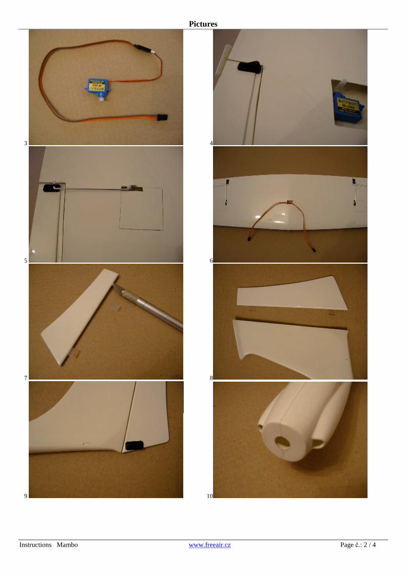
Building process:First, cut open the compartment for the aileron servo, using a sharp modelling knife (Fig.1). Do not cut through the full thickness of the skin on theleading edge side of the compartment – just scrape some of the material away to leave enough of it to serve as a hinge of the servo compartmentcover (use the same method to make the aileron hinges). Then cut the opening for the aileron servo cabling (Fig.2). A 30 mm-long servo cableextension should suffice for the aileron servo connection (Fig.3). Use the CA glue or melting glue gun to attach the aileron servos in theircompartments. Using the CA glue, cement the aileron control horn so that it is in line with the servo arm axis (Fig. 4). Install the aileron controlrods (Fig.5). With a sharp modelling knife, cut the slits for hinges in the rudder and vertical fin (Fig.7, 8). Glue the hinges into the slits in therudder, then attach the rudder to the vertical fin. Glue the rudder control horn in place (Fig.9). Using a milling cutter or a sharp knife, create themotor cooling air inlet and outlet openings (Fig.10). Glue the elevator and rudder push-pull rod guide tubes in place (Fig.11). Glue the elevatorcontrol arm in place and install the elevator control rod (Fig.12, 13). Bolt the elevator and rudder servos into the bulkhead (Fig.14). Glue thecontrol rod guide tubes into the fuselage and insert the elevator and rudder control rods to them (Fig.15, 16). Cut out the undercarriage wheelsfairings (Fig.17). Paint the cockpit canopy as you like best (Fig.18). Assemble the undercarriage – insert the bolt into the wheel and secure with anut (Fig.19). Then put the wheel fairing in place and secure with a second nut to the duraluminium leg (Fig.20, 21). Attach the legs in place usingtwo screws (Fig.22). Using a 3 mm diameter drill, make a hole for the wing centring peg. Attach the cockpit canopy, using the CA glue (Fig.23).Attach the motor in place, using bolts, and secure the propeller (Fig.24). By shifting the battery balance the model. Its centre of gravity should lie73 mm from the wing leading edge.
This model is no toy – therefore avoid flying in crowded or such places where health or property not only of yourselves, but also of thirdpersons could be jeopardised..
Many happy landings wishes FreeAir.
1 2
Pictures
Instructions Mambo www.freeair.cz Page č.: 2 / 4
3 4
5 6
7 8
9 10

Pictures
Instructions Mambo www.freeair.cz Page č.: 3 / 4
11 12
13 14
15 16
17 18

Pictures
Instructions Mambo www.freeair.cz Page č.: 4 / 4
19 20
21 22
23 24