Embed Size (px)
Citation preview

DEVELOPMENT OF AN OPTIMAL DRAGONFLY-LIKE
FLAPPING WING STRUCTURE FOR USE IN BIOMIMETIC
MICRO AIR VEHICLES
PRAVEENA NAIR SIVASANKARAN
THESIS SUBMITTED IN FULFILMENT OF THE
REQUIREMENTS FOR THE DEGREE OF DOCTOR
OF PHILOSOPHY
FACULTY OF ENGINEERING
UNIVERSITY OF MALAYA
KUALA LUMPUR
2015
Univers
ity of
Mala
ya
ii
UNIVERSITY OF MALAYA
ORIGINAL LITERARY WORK DECLARATION
Name of Candidate: (I.C/Passport No: )
Registration/Matric No:
Name of Degree:
Title of Project Paper/Research Report/Dissertation/Thesis (“this Work”):
Field of Study:
I do solemnly and sincerely declare that:
(1) I am the sole author/writer of this Work;
(2) This Work is original;
(3) Any use of any work in which copyright exists was done by way of fair
dealing and for permitted purposes and any excerpt or extract from, or
reference to or reproduction of any copyright work has been disclosed
expressly and sufficiently and the title of the Work and its authorship have
been acknowledged in this Work;
(4) I do not have any actual knowledge nor do I ought reasonably to know that
the making of this work constitutes an infringement of any copyright work;
(5) I hereby assign all and every rights in the copyright to this Work to the
University of Malaya (“UM”), who henceforth shall be owner of the
copyright in this Work and that any reproduction or use in any form or by any
means whatsoever is prohibited without the written consent of UM having
been first had and obtained;
(6) I am fully aware that if in the course of making this Work I have infringed
any copyright whether intentionally or otherwise, I may be subject to legal
action or any other action as may be determined by UM.
Candidate’s Signature Date:
Subscribed and solemnly declared before,
Witness’s Signature Date:
Name:
Designation:
Univers
ity of
Mala
ya
iii
ABSTRACT
Biomimetic Micro Air Vehicles (BMAV) are unmanned, micro-scaled aircrafts that are
bioinspired from flying organisms to achieve lift and thrust by flapping their wings.
Micro Air Vehicles (MAV) are a relatively new and rapidly growing area of aerospace
research. They were first defined by the US Defense Advanced Research Projects
Agency (DARPA) in 1997 as unmanned aircraft that are less than 15 cm in any
dimension. This allows BMAV to potentially be smaller and more lightweight than the
other two types. These characteristics make BMAV ideally suited for flight missions in
confined areas (e.g. around power lines, narrow streets, indoors, etc.). Therefore,
BMAV structural components must be ultra-lightweight, compact, and flexible. Most
past MAV research has focused on fixed wings, which are essentially scaled-down
versions of wings on conventional fixed wing aircraft. These wings are unsuitable for
BMAV due to their lack of flexibility. So a new type of structural wing design is
required for BMAV. In this work, a dragonfly wing structure is mimicked to construct a
new BMAV wing design. A dragonfly (Odonata) was selected for biomimicry, because
they are highly maneuverable flyers, capable of hovering, rapid forward flight, or
reverse flight. Therefore, structurally analyzing these wings could yield results that
inspire the design of more effective wings for BMAVs. The overall objective of this
research is to develop a simplified wing model for a BMAV, bioinspired from actual
dragonfly wings. A simplified model was created using spatial network analysis, a
topological optimization method. These simplified wing frame models were then
fabricated using seven different types of materials. Stainless steel type 321, balsa wood,
red pre-impregnated fiberglass, black graphite carbon fiber, polyvinyl acid, acrylic and
acrylo-nitirile butadiene styrene. These wing frame structures were fabricated using
laser cutting machine and a 3D printer. These wing frames were then immersed in a
chitin-chitosan membrane by a casting method. These wing frames were subjected to
Univers
ity of
Mala
ya
iv
mechanical testing’s such as bending and tensile to study its suitability for use in a
BMAV. A flapping mechanism was also created and used to produce flapping motion
on these BMAV wings and an actual dragonfly wing (for comparison). The aero elastic
properties of both the BMAV and actual dragonfly wings were examined using two
high speed frame camera. The bending angle, displaced distance or deflection, wing tip
angle, and the wing tip rotational twist speed were analyzed at the flapping frequencies
of 10,20, 30 Hz, 60 Hz and 120 Hz.
Univers
ity of
Mala
ya

v
ABSTRAK
Kenderaan udara mikro biomimetic merupakan sebuah jentera yang tidak memerlukan
pemandu dan bersaiz mikro. Inspirasi untuk mereka bentuk kenderaan seperti ini
diperoleh dari melihat serangga yang boleh terbang. Kenderaan udara mikro ini
merupakan teknologi yang baharu dan sedang berkembang di dalam bidang
aeroangkasa. Kenderaan mikro ini memporeleh definisi daripada US Defense Advanced
Research Projects Agency (DARPA) pada tahun 1997. Mereka mengkategorikan
kenderaan tanpa pemanudu ini haruslah mempunyai ukuran dimensi yang kurang
daripada 15 cm. Ini menjadikan BMAV kecil dan ringan berbanding kenderaan udara
yang lain. Ini juga membolehkan BMAV sesuai digunakan di kawasan yang kecil dan
sukar dilalui manusia ( kawasan yang dikelilingi kabel voltan tinggi serta lorong yang
sempit). Maka, komponene struktur BMAV mestilah ultra-ringan, padat dan fleksibel.
Kajian terdahulu memberi tumpuan kepada sayap yang statik yakni mengurangkan skala
kapal terbang yang sedia ada. Sayap seperti ini tidak sesuai bagi kenderaan udara mikro
disebabkan kurangnya fleksibiliti. Jadi, struktur sayap yang baharu direka untuk BMAV
ini. Di dalam penyelidikan ini, sayap pepatung telah dimimik untuk merekabentuk
sayap baru bagi BMAV ini. Spesis pepatung (Odonata) telah dipilih untuk dimimik
keranapepatung merupakan serangag terbang yang sangat efisien. Pepatung boleh
melakukan pelbagai aksi sewaktu terbang seperti terbang tanpa mengibas sayapnya
untuk waktu yang lama, terbang sambil menukar arah, atau terbang songsang. Objektif
penyelidikan ini adalah untuk merekabentuk sayap model sayap yang telah
disimplifikasikan untuk BMAV. Sayap pepatung menjadi model inspirasi kami. Sayap
pepatung ini disimplifikasikan menggunakan kaedah optimasi yang dinamakan “ spatial
network analysis’. Tujuh jenis bahan digunakan untuk menghasilkan model sayap ini.
Keluli tahan karat jenis 321, kayu balsa, fiberglass merah, carbon fiber, polyvinyl acid,
acrylic and acrylo-nitrile butadiene styrene. Sayap ini dihasilkan menggunakan mesin
Univers
ity of
Mala
ya
vi
laser dan printer 3D. Sayap ini kemudiannya disalut dengan membran chitin-chitosan.
Ujian tegangan dan lenturan dijalankan ke atas sayap ini. Sebuah mekanisme yang
memiliki kebolehan mengimbas disediakan bagi menguji kebolehan sayap-sayap yang
dihasilkan ini. Bagi membandingkan kebolehan sayap-sayap ini, sayap pepatung yang
sebenar juga diuji di atas mekanisme ini. Kebolehan aero-elastik sayap sayap ini diukur
dan dibandingkan dengan sayap pepatung yang asal menggunakan dua kamera halaju
tinggi. Ukuran seperti sudut lenturan, jarak imbasan, sudut hujung sayap, sudut putaran
hujung sayap dan halaju putaran hujung sayap diuji pada frekuensi 10, 20, 30, 60 dan
120 Hz.
Univers
ity of
Mala
ya
vii
DEDICATIONS
this thesis is dedicated especially
to my beloved father, mother, and husband
Mr. Sivasankaran Nair, Mrs. Santhakumari and Mr. Rajendra Nath
The caring ones,
Kishan Nair Sivasankaran, Rubentheren Viyapuri
Respected supervisors,
Dr. Thomas Arthur Ward
Associate Professor Dr. Mohd Rafie Johan
Thanks for all the support.
My love for you all remains forever.
Univers
ity of
Mala
ya

viii
ACKNOWLEDGEMENT
I take this opportunity to express my profound gratitude to my supervisor Dr.
Thomas Arthur Ward for his exemplary guidance, monitoring, patience and constant
encouragement throughout the duration of my studies. I would also like to
acknowledge with much appreciation the supportive role of my co-supervisor Associate
Professor Dr. Mohd Rafie Johan for guiding me professionally throughout the
candidature.
I would like to express the deepest appreciation to all my lab members Mr.
Rubentheren Viyapuri, Mr. Christopher Fearday and Mr. Erfan Salami. I’m thankful for
being blessed with a friendly and cheerful group. They were always there to lend me a
helping hand under many situations. I wish to take this opportunity to express my
heartfelt gratitude to all of them. I also take this opportunity to express a deep sense of
appreciation to lab assistants Mr. Fauzi who have helped me during my lab experiments.
Special thanks to University Malaya for sourcing me a quality workstation.
Of course no acknowledgments would be complete without giving thanks to my
family. I would like to thank my family for their unconditional support. In particular,
the motivation and encouragement given by my husband has helped me pull through
many critical situations throughout my candidature. Also, the absolute love and
blessings showered by my mum, dad, and brother. A special thanks to Rubentheren
Viyapuri for being a good friend in need.
Above all, I thank God for his grace, wisdom, favor and protection. I could
never have done this without the faith I have in you, Baba.
There are so many others whom I may have inadvertently left out and I sincerely
thank all of them for their help.
Univers
ity of
Mala
ya

ix
TABLE OF CONTENTS
PAGE
ABSTRACT iii
DEDICATION vii
ACKNOWLEDGEMENT viii
TABLE OF CONTENT ix
LIST OF FIGURES xiv
LIST OF TABLES xvii
LIST OF SYMBOLS AND ABBREVIATIONS xviii
LIST OF APPENDICES xxii
CHAPTER 1: INTRODUCTION 1
1.1 Biomimetics 1
1.2 Unmanned aerial vehicles (UAVs) 1
1.3 Problem statement 3
1.4 Objectives 5
1.5 Procedures 7
1.6 Outline of thesis 7
CHAPTER 2: LITERATURE REVIEW 9
2.1 Introduction 9
2.2 Insect flight 9
2.3 Dragonflies 10
2.4 Spatial network analysis 17
Univers
ity of
Mala
ya

x
2.5 Fabrication of artificial insect wings 19
2.6 Frequencies of insect wings 21
2.7 Static test conducted on real and artificial wings 22
2.8 Flapping mechanism 23
2.9 Ornithopters 23
2.10 High speed camera imaging technique 24
CHAPTER 3: RESEARCH METHODOLOGY 26
3.1 Introduction 26
3.2 Wing model overview 26
3.3 Spatial network analysis 28
3.3.1 Canny edge detection algorithm 28
3.3.2 Proximity index 31
3.3.3 CAD model 34
3.4 Finite element analysis 35
3.4.1 Element and mesh 37
3.4.2 Modal analysis: Mode shapes and MAC 39
3.5 Artificial wing frames and nano-composite chitosan membrane 41
3.5.1 Fabrication of stainless steel (Type 321) wing frame s 40
3.5.2 Fabrication of balsa wood wing frames 42
3.5.3 Fabrication of black graphite carbon fiber wing frames 42
3.5.4 Fabrication of red prepreg fiberglass wing frames 44
3.5.5 Fabrication of polylactic acid (PLA) wing frames 45
Univers
ity of
Mala
ya

xi
3.5.6 Fabrication of acrylic wing frames 45
3.5.7 Fabrication of acrylonitrile butadiene styrene ABS wing frames 46
3.5.8 Chitosan nano-composite solution (membrane) 47
3.6 Numerical bend-twist coupling and static strength simulation
analysis 48
3.6.1 Numerical bend-twist coupling analysis 48
3.6.2 Static strength simulation analysis 48
3.7 Experimental set up 49
3.8 Flapping mechanism 53
CHAPTER 4: RESULTS AND DISCUSSION 55
4.1 Introduction 55
4.2 Simplified model creation 55
4.3 Mode shape analysis and MAC 59
4.4 Numerical bend-twist coupling analysis 64
4.5 Tensile test simulation result 66
4.5.1 Tensile simulations (wing frames without membranes) 66
4.5.2 Tensile test simulations results (wing frames with membrane) 71
4.5.3 Bending test simulation results (wing frames without membrane) 73
4.5.4 Bending test simulation results (wing frames with membrane) 75
4.5.5 Tensile test experimental results 76
4.5.6 Bending test experimental results 84
4.6 High speed camera image results analysis 87
Univers
ity of
Mala
ya
xii
4.6.1 Bending angle versus flapping frequency 92
4.6.2 Wing tip deflection versus flapping frequency 95
4.6.3 Wing twist angle versus flapping frequency 97
4.6.4 Wing tip twist speed versus flapping frequency 99
CHAPTER 5 – CONCLUSION 102
5.1 Summary 102
5.2 Future work 106
REFERENCES 107
LIST OF PUBLICATIONS 119
APPENDICES 121
Univers
ity of
Mala
ya
xiii
LIST OF FIGURES
PAGE
Figure 1.1 Illustration of the overall procedures in developing a
BMAV wing frame 7
Figure 2.1 Dragonfly species used in this study 11
Figure 2.2 Strokes of wings during flapping motion 11
Figure 2.3 The front view of a dragonfly in flight 15
Figure 2.4 Schematic diagram of Gui et al (2010) of fire ant alate
wing motion 25
Figure 3.1 Main parts of a dragonfly wing 27
Figure 3.2 Spatial Network Model 33
Figure 3.3 (a) Digital image of the forewing of a dragonfly;
b) forewing created by Canny edge algorithm;
c) Canny edge forewing created after noise
minimization and main pattern identification;
d) forewing CAD model 34-35
Figure 3.4 Stainless steel type 321 wing frames; a) forewing,
b) hindwing 41
Figure 3.5 Balsa wood wing frames; a) forewing, b) hindwing 42
Figure 3.6 Waviness of carbon fiber yarns 43
Figure 3.7 Black graphite carbon fiber wing frames; a) forewing,
b) hindwing 43
Figure 3.8 Red pre-preg fiberglass wing models after immersion
in chitosan nanocomposite solutions;
a) forewing, b) hindwing 44
Figure 3.9 PLA wing models after immersion in chitosan
nano-composite solutions; a) forewing, b) hindwing 45
Figure 3.10 Acrylic wing models after immersion in chitosan
nano-composite solutions; a) forewing, b) hindwing 45
Figure 3.11 ABS wing models after immersion in chitosan
nano-composite solutions; a) forewing, b) hindwing) 46
Figure 3.12 Wing structure immersed in chitosan nanocomposite
solution; (a) fore wing, (b) hind wing 47
Univers
ity of
Mala
ya

xiv
Figure 3.13 Placement of constraints fixed in a natural frequency
analysis 48
Figure 3.14 Constraints for a static strength analysis 49
Figure 3.15 INSTRON Universal testing machine 51
Figure 3.16 (a) Actual experimental set up of the high speed camera
imaging technique, (b) Schematic diagram of the
experimental set up 51-52
Figure 3.17 Front view (a) and side view (b) of the wing motion
captured and measurement axes. 52
Figure 3.18 Flapping mechanism used in this research 54
Figure 4.1 Fabricated simplified model (a) forewing;
(b) hindwing 55
Figure 4.2 Typical dragonfly wing membrane pattern arrangement 57
Figure 4.3 Example of connecting strong edges using cloud points 58
Figure 4.4 Simplified models, (a) forewing, (b) hindwing 59
Figure 4.5 Similar mode shapes and corresponding natural
frequencies for both detailed (left) and simplified
models (right) : forewing 60
Figure 4.6 Similar mode shapes and corresponding natural
frequencies for both detailed (left) and simplified
models (right) : hindwing 61-62
Figure 4.7 The static bend-twist coupling graph of both detailed
and simplified models; forewing 64
Figure 4.8 The static bend-twist coupling graph of both detailed
and simplified models; hindwing 65
Figure 4.9 Von Misses stress simulation results of different forewing
frame structures; (a) stainless steel (Type 321),
(b) balsa wood, (c) black graphite carbon fiber,
(d) red prepreg fiberglass e) PLA, f) acrylic, g) ABS 68
Figure 4.10 Von Misses stress simulation results of different forewing
frame structures; (a) stainless steel (Type 321), (b) balsa
wood, (c) black graphite carbon fiber, (d) red prepreg
fiberglass, e) PLA, f) acrylic, g) ABS 69
Univers
ity of
Mala
ya
xv
Figure 4.11 von Misses stress simulation results of different
forewing model structures; (a) stainless steel (Type 321),
(b) balsa wood, (c) black graphite carbon fiber,
(d) red prepreg fiberglass, (e) PLA, (f) acrylic, (g) ABS 71
Figure 4.12 von Misses stress simulation results of different
forewing model structures; (a) stainless steel (Type 321),
(b) balsa wood, (c) black graphite carbon fiber,
(d) red prepreg fiberglass, (e) PLA, (f) acrylic, (g) ABS 72-73
Figure 4.13 von Misses stress simulation results of different forewing
model structures; (a) stainless steel (Type 321),
and (b) balsa wood 74
Figure 4.14 Von Misses stress simulation results of different hindwing
model structures; (a) stainless steel (Type 321),
and (b) balsa wood 74
Figure 4.15 von Misses stress simulation results of different forewing
model structures; (a) stainless steel (Type 321),
and (b) balsa wood 75
Figure 4.16 von Misses stress simulation results of different hindwing
model structures; (a) stainless steel (Type 321),
and (b) balsa wood 75
Figure 4.17 Tensile stress vs tensile strain (engineering) of all four
forewing frame structures ; a) stainless steel (Type 321),
b) balsa wood, c) black graphite carbon fiber,
d) red prepreg fiberglass, e) PLA, f) acrylic and g) ABS 80-82
Figure 4.18 Tensile stress vs tensile strain (engineering) of all four
hindwing frame structures ; a) stainless steel (Type 321),
b) balsa wood, c) black graphite carbon fiber,
d) red prepreg fiberglass, e) PLA, f) acrylic and g) ABS 82-83
Figure 4.19 Comparison stress vs comparison strain graphs of forewing
wing models; a) stainless steel (Type 321) ,b) balsa wood 85
Figure 4.20 Comparison stress vs comparison strain graphs of hindwing
wing models; a) stainless steel (Type 321) ,b) balsa wood 86
Figure 4.21 Degrees of freedom for the wings of flying insects 88
Figure 4.22 Side view of the dragonfly flapping wing (gray scale)
captured by the high speed camera during one flapping
cycle at 30Hz. a) start of downstroke, b) mid-downstroke,
c) end of downstroke, d) start of upstroke, e) mid-upstroke,
f) end of upstroke 89
Univers
ity of
Mala
ya
xvi
Figure 4.23 Front view of the dragonfly flapping wing (gray scale)
captured by the high speed camera during one flapping
cycle at 30Hz. a) start of downstroke, b) mid-downstroke,
c) end of downstroke, d) start of upstroke, e) mid-upstroke,
f) end of upstroke 90
Figure 4.24 Bending angle of different wing frames;
(a) without membrane and (b) with membrane 94
Figure 4.25 Wing tip deflection of different wing frames;
(a) without membrane and (b) with membrane 96
Figure 4.26 Wing twist angle of different frames versus flapping
frequency; (a) without membrane and (b) with membrane 98
Figure 4.27 Wing tip twist speed of different frames versus flapping
frequency; (a) without membrane and (b) with membrane 100
Univers
ity of
Mala
ya
xvii
LIST OF TABLES
PAGE
Table 3.1 Properties of Teflon 38
Table 3.2 Mechanical properties of frame structure materials 40
Table 3.3 Specifications of black graphite carbon fiber 43
Table 4.1 Model Specifications in Terms of Number of Membranes,
Density and Patterns 56
Table 4.2 MAC values for all five compared mode shapes for both
forewing and hindwing 63
Univers
ity of
Mala
ya

xviii
LIST OF SYMBOLS AND ABBREVIATIONS
Symbols and Abbreviations Full name
UAV Unmanned aerial vehicle
MAV Micro air vehicle
BMAV Biomimetic micro air vehicle
Hz Hertz
PLA Polylactic acid
ABS Acrylonitrile-butadiene styrene
dpi Dots per inch
m Meter
μ Micro
FEA Finite element analysis
ω circular frequency
θ Bending angle
d Displaced distance or deflection
α Wing tip angle
CAD Computer aided design
3D three dimensional
mm millimeter
Univers
ity of
Mala
ya

xix
MPa Mega Pascal
GPa Giga Pascal
Univers
ity of
Mala
ya
xx
LIST OF APPENDICES
PAGE
Appendix A Force displacement graph of dragonfly fore wing 121
Appendix B Force displacement graph of dragonfly hind wing 123
Appendix C Force displacement graph of BMAV fore wing 126
Appendix D Force displacement graph of BMAV hind wing 128
Univers
ity of
Mala
ya

1
CHAPTER 1: INTRODUCTION
1.1 Biomimetics
Biomimetics or biomimicry is a concept of imitating elements of nature to solve or
to ease complex human tasks. The terms biomimetics and biomimicry come from Ancient
Greek: biosmimesis or biosmios which means imitating life (Julian et al. 2006). The
development of biomimetics has created new bio-technological solutions at macro and
nanoscales. The application of biomimetics can be seen in many fields from cars to
computers. Optimization methods such as swarm intelligence and artificial neural networks
were inspired by biomimetics. There are three areas in where biotechnological solutions
can be applied (Rhett Butler, 2015): Replicating natural production methods (chemical
compounds from plants), Mimicking mechanisms found in nature (dragonfly, Velcro) and
finally observation of social behavior of organisms (ants and bees).
1.2 Unmanned aerial vehicles (UAVs)
The Unmanned Aerial Vehicle or commonly known as UAV, is an aircraft with no
pilot on board. UAVs can be controlled by a ground control station, routed by pre-
programmed flight plan or fitted with a complex automation system. UAVs are currently
used for a number of missions, including reconnaissance and attack roles.
Micro air vehicles (MAV) are a new type of unmanned air vehicle which is
significantly smaller than a UAV. Defense Advanced Research Projects Agency defines a
MAV as an aircraft which has a size less than 15 cm in length, width or height. This puts
MAV smaller than any UAV developed to date. MAVs should be thought of as aerial
robots, whose mobility will allow them to be deployed to remote or hazardous locations to
perform a variety of missions which includes surveillance, targeting and even rescue
Univers
ity of
Mala
ya
2
missions. (Michelson et al, 2002). There are different types of MAVs such as fixed wing
models, (FMAVs) rotary wing models (RMAVs) and insect-like (flapping wing) models,
(BMAVs). FMAVs are micro-scaled air vehicles with fixed (stationary) wings that
generates lift but not thrust. There is a separate system attached (propulsion) to generate
thrust. They are used in non-confined spaces because they should maintain a continuous
forward velocity in order to generate lift (wings). Rotors are used to achieve lift and thrust
for RMAVs. Since they are able to hover they are much efficient than FMAV. However,
the size is their limitation. RMAVs are generally larger than FMAVs or BMAVs. BMAVs
are micro or nano-scaled aerial vehicles biomimicked from a biological organism. BMAVs
are the smallest MAVs designed and they have flexible flapping wings. Due to their small-
size range, the BMAVs are able to travel in confined spaces. According to James and
Michael (1997) the system components in a MAV should be integrated and possess
multifunctional characteristics to be able to overcome the challenge faced in designing an
aircraft with constrained dimensions. A MAV may only weigh about 50 grams yet; MAVs
must be capable of hovering as long as 20 to 60 minutes while carrying a load of 20 grams
a distance of approximately 10 km. It is essential to find the suitable materials and the
optimum structural balance for a MAV (James and Michael, 1997).
1.3 Problem statement
The study of biomimetics as mentioned earlier has motivated research into a new
class of micro-sized unmanned aircraft called Biomimetic Micro Air Vehicles (BMAVs).
Due to their small size and weight, BMAVs would be ideal for flying indoors or in
enclosed spaces. The primary payloads envisioned for a BMAV are ultra-lightweight,
compact electronic and surveillance detection equipment. Their miniature size makes them
difficult to detect, easy to quickly deploy by a single operator and relatively inexpensive to
fabricate, and allows the potential to fly them inside buildings or compact spaces. BMAVs
Univers
ity of
Mala
ya
3
are envisioned for use on civil and military missions that are of a limited duration, such as:
remote sensing of hazard sites (e.g. chemical spill, radiation, high voltage power lines etc.),
indoor video mapping, and police or military surveillance.
Some research has been conducted to biomimic the wing structure of dragonflies.
TU Delft researchers have developed the DelFly Explorer, a low weight (20 grams) MAV
which flaps and avoid obstacles autonomously (Michelson et al, 2002). Festo created
BionicOpter, a fully functional robotic dragonfly which is able to perform the aerial
acrobats of an actual dragonfly. BionicOpter is much larger than an actual dragonfly with a
weight of 175grams (TA Ward et al, 2015). Dragonflies (Odonata) have a highly
corrugated wing structure that consists of complex, wing membrane patterns (e.g.
quadrilaterals, pentagons and hexagons). Each pattern contributes to the wing’s flexibility
and stiffness, which determine its ability to withstand deformations. Although some
research has been conducted to biomimic the wing structure of dragonflies. (Tu Delft, 2013
and Yirka, 2013), none of these works biomimicked the actual wing structures of
dragonfly. Although other insect wings (e.g. cicada, beetle, etc.) have been replicated,
dragonfly wing structures are very complex making this difficult. Dragonfly wings are
highly corrugated in pattern, with differing thickness and tubular structures. Replicating an
exact copy is not a practical approach, due to limitations in fabrication methods. So a
simplified model is needed that takes these limitations into consideration. Like the wings of
a flying insect, the artificial wings of a BMAV not only must be flexible but also strong
enough to endure the aerodynamic forces produced by flapping motion. During flight, the
wings undergo significant bending and twisting deformations that can alter the direction
and magnitude of the aerodynamic forces generated (Combes S, 2003, 2010, Shang J.K et
al, 2009)
Univers
ity of
Mala
ya
4
Several fabrication methods for small insect-scale artificial wings have been
proposed. Combes and Daniel (2010) measured the wing flexibility of several insects and
found that the spanwise flexural stiffness was one to two orders of magnitude larger than
the chordwise flexural stiffness. The scope of their investigation was limited due to the
diversity in venation as well as the complex cross-sectional and planform geometries of the
insect wings. In contrast, the morphology and materials of artificial wings can be
manipulated to understand the effect of these properties on wing flexibility. Tanaka and
Wood (2010) investigated the effects of flexural and torsional wing flexibilities on lift
generation in hoverfly flight using an insect-scaled mechanical model of an artificial wing.
There are several past research studies that focus on insects such as hoverfly, beetle and
humming (Tanaka et al. 2010, Nguyen et al. 2010 and David et al. 2014). Also, most past
literature involves wing membrane materials (Bao, 2011, Ko, 2012, Joong, 2013). Very
little has been written about the BMAV wing frame structures that encase the membrane.
Several past research publications have been conducted on flying insect wing structures to
understand their aeroelastic properties. Ward et al. (2015) conducted a review on the
percentage of flying organisms studied; hawkmoth (44%), dragonfly (23%), beetle (10%),
butterfly and humming bird (7%), bat (4%), fruit fly (3%), honey bee (2%) and damselfly
(1%). Herbert et al. (2000) conducted numerical investigations on a tethered desert locust
(Schistocerca gregaria). They concluded that the wings must undergo an appropriate
aeroelastic wing deformation (through the course of a wing beat) in order to achieve an
efficient aerodynamic flow suitable for lift and thrust generation. Several studies showed
that flexible wings, capable of changing their camber, generate higher peak lift forces than
rigid wings (Mountcastle and Young, 2009).
Wing flexibility also prevents small tears or warping from occurring. Newman et al
(1986) suggested that dragonfly wings appear to be adapted for reversible failure in
Univers
ity of
Mala
ya

5
response to excess loads, enabling them to avoid permanent structural damage. Most past
research examined the effects of wing flexibility on aerodynamic performance by either
using numerical models or experimentation. However, very few researchers have attempted
to mimic the detailed structure of an actual insect wing. Hence, the overall objective of this
research would be to create a simplified dragonfly wing model for use in a BMAV. This
wing model is envisioned to be able to match the performance of an actual dragonfly wing.
1.4 Objectives
The overall objective of this research is to model a simplified dragonfly wing that
matches the performance and capabilities of an actual dragonfly wing. Firstly, a simplified
model of the complex corrugated dragonfly wing is created. As previously stated, this
model has a simplified design to suit appropriate machining tolerances. A mode analysis
and static bend-twist coupling studies were made on computer simulations of these models.
Secondly, these simplified models were fabricated using different materials. Simulations
and tensile and bending experimental tests were done to determine the most suitable
material. Thirdly, the most promising materials were attached onto a flapping mechanism
and their aero-elastic properties were measured. These were compared with an actual
dragonfly wing for comparison purposes. Listed below is a summary of the objectives
performed: analysis of dragonfly-inspired BMAV wing structures (e.g. patterns, veins, and
tubules of dragonfly wings) includes designing a simplified wing structure optimized using
spatial network analysis, conducting finite element analysis including modal analysis and
other mechanical simulation testing on the simplified design (static bend-twist coupling),
fabricating simplified wings using different materials (e.g. steel, balsa wood, carbon fiber,
red fiberglass, acrylic, ABS, and PLA), conducting mechanical testing on fabricated wings
to ensure it matches the capability of an actual dragonfly wing and finally to test the
Univers
ity of
Mala
ya

6
fabricated wings (chosen material) on a flapping mechanism to assess the performance of
each design.
1.5 Procedures
Figure 1.1 below shows the summary of the procedures involved in the fabrication
of these wings.
Figure 1.1: Illustration of the overall procedures in developing a BMAV wing frame
Figure 1.1 describes the overall steps involved in this research. It starts with a
comprehensive literature review which includes a research of dragonflies and BMAV in
general and research of dragonfly wing structures specifically. The second step involves
design and modeling of simplified wing structures using spatial network analysis, FEA
(finite element analysis), modal analysis, and static bend twist analysis. The third step
involves fabrication of the wings using different method (manual carving, laser machining
and 3D printer) and finally testing these fabricated wings on a flapping mechanism.
Univers
ity of
Mala
ya

7
1.6 Outline of thesis
There are five chapters in this thesis, and a list summarizing them is as stated. The
first chapter introduces BMAV and their potential applications. It provides an overview of
this research and lists the primary objectives. It also lists layout of the procedure for
accomplishing these objectives, the second chapter reviews past researches done with a
similar objective. It gives a brief review of past research done on dragonflies and other
related topics that subsequently contributes to this research. Other review on related topics
include mechanism of insect flight, simulation of insect flights, flapping mechanism
created by other researchers, finite element analysis studies done on insect flight,
fabrication of artificial wing frame and membranes of insect and the high speed camera
imaging technique. In the third chapter, experiments are discussed extensively. Sufficient
details are given so that future readers can replicate this work. It discusses the topological
optimization method used which is spatial network analysis, the finite element analysis
options chosen and the mode analysis study made for both detailed and simplified wings,
the mode shape comparison, the static bend-twist study conducted, the materials used for
the fabrication of the simplified wing models, the simulation and experimental tests done
on the fabricated wing frames and, finally, the high speed camera technique used to capture
the parameters necessary for an aero-elastic study, The fourth chapter discuss and assesses
all the data acquired from the experiments. Where possible, these results are compared with
data collected by other researchers, and the last chapter summarizes and concludes this
research. It lists the experience and challenges faced while performing these studies and
also suggest improvements that can be done in future studies.
Univers
ity of
Mala
ya

8
CHAPTER 2: LITERATURE REVIEW`
2.1 Introduction
This chapter highlights several subtopics that were studied to support this research.
The chapter introduces insect flight concepts, the wing structure of dragonflies, the spatial
network analysis, the type of artificial wings fabricated in previous insect studies, testing
conducted in previous studies, types of flapping mechanisms, and data collected from
previous high frame rate imaging system studies.
2.2 Insect flight
The size of insect wings is not an indication of the insects’ ability to fly. Flies and
certain types of ants (Dobsonflies and Antlions) with large wings are poor fliers when
compared to wasps and bees that have smaller wings (Smithsonian, 2010). Flight in insects
enabled them to protect themselves from danger, as a means of survival (food hunting),
reproduction, and to search for new habitats (Monarch Butterflies) (Rose, n.d)
Wing flapping patterns of insects can vary significantly from one species to another.
The African Grasshopper, has the ability to fly hundreds of miles in search of food. This is
mainly attributed to their complex wing structure (“Smithsonian”, 2010). Wings typically
make up approximately 1%-2% of an insect’s total body mass. In dragonflies, they must
flap a million times in an average lifespan of an insect but not without enduring collisions,
torsional loads and other various forms of deformation (Kutsch, 2002).
2.3 Dragonflies
Separate muscles control the fore and hind wings, making the phase relation
between the 2 parts as a distinctive feature of the dragonfly’s wing movement. For an
example, both parts tend to beat closer in phase during takeoff but out of phase when
Univers
ity of
Mala
ya
9
hovering. A reduction in oscillation is the main reason the dragonfly varies the phase for
different maneuvers. The relatively close distance between the fore and hind wings, about a
wings width apart, allows both parts to interact aerodynamically (Jane, 2004).
Dragonflies have shown different flight styles. The four different flight styles
observed in dragonflies are (Norberg, 1975): Counter stroking (fore and hind wings move
up and down about 180 degrees non-symmetrically), phase stroking (hind wings cycle
about 90 degrees before the fore-wings), synchronized stroking (fore and hind wings move
in unison) and gliding
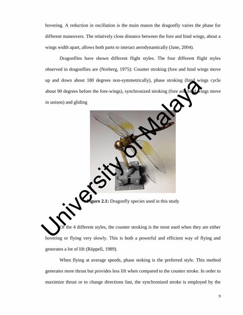
Figure 2.1: Dragonfly species used in this study
Of the 4 different styles, the counter stroking is the most used when they are either
hovering or flying very slowly. This is both a powerful and efficient way of flying and
generates a lot of lift (Rüppell, 1989).
When flying at average speeds, phase stoking is the preferred style. This method
generates more thrust but provides less lift when compared to the counter stroke. In order to
maximize thrust or to change directions fast, the synchronized stroke is employed by the
Univers
ity of
Mala
ya
10
dragonfly. Finally, gliding where three different types of gliding have been recognized
(Reavis et al, 1988); free gliding ; where the insect stops stroking and glides slowly down,
updraft gliding at hill crests ; where the insect adjusts its wing position to float in the air
without the need to beat its wings, gliding in towed females ; where the female insect in the
wheel position holds her wings out and glides while the male provides the motion force.
(This is during the mating position). The muscles used to flap the wings are attached to the
wing base. Elevated muscle temperature increases flapping efficiency. For this reason the
dragonfly spends a lot of time and energy to maintain their flight muscles at elevated
temperatures (Reavis et al. 1988, Saharon et al. 1987). The dragonfly thorax appears
skewed when at rest, but at flight, the head is held low and the stroke of the wings are
parallel to the long axis of the flight muscles. This is done to improve mechanical
efficiency. During each stroke, smaller controller muscles (operating at the base of the
wings) adjust the wing shape and angle of attack. Four different thrust generating
mechanics may be employed by the dragonfly (Sun, 2002). The four different mechanisms
used by the dragonfly are: classical lift, supercritical lift, vortices and vortex shedding.
When the attack angle of the wing passes a critical value, supercritical lift occurs.
Similar to hovering, a high lift is generated over a short distance after which the wing stalls.
Dragonflies can maintain this position continuously by using short wing strokes. The use of
vortices and shed vortices in insect flight by Usherwood et al. (2002) was explored. Both
the movement of the wings through the air and the twisting of the wings at the end of each
stroke to generate thrust.
Dragonfly wings are not simple planar objects but complex dynamic structures. The
corrugations in the wings holding an aero-foil of air around the wings have the following
effects: Lower friction, wings are able to flex around several axes, and being able to
respond to both muscle actions and to inertia effects. The pterostigma on the leading edge
Univers
ity of
Mala
ya

11
near the tip of the wings are weights that improve the aerodynamic efficiency by causing
the wing tip to flex during a wing stroke. Dragonflies can fly with asymmetrical wing
stokes. This is achieved by varying what their wings are doing in a coordinated fashion.
They have to master to adjust wing shape, stroke length, angle of attack, stopping either
wings independent of the other and adjusting the relationship between any two wings on
either side of the body are among a few of the many subtle adjustments made in order to
maintain their flight style (Ellington, 1984 (a),(b) and 1985).
Dragonflies have a natural frequency range of 120-200 Hz and a wingbeat
frequency of around 30Hz. The flapping of the wings creates a whirlwind surrounding the
wing area. A dragonfly uses a rowing motion along an inclined stroke plane. When
hovering, the body lies almost horizontal while the wings push backward and downward
with the addition of the feathers slicing upwards and downwards at the end of each stroke
(Grodnitsky, 1999). In contrast to the dragonflies asymmetrical rowing motion, many other
insects use symmetrical back and forth strokes near a horizontal stroke plane. This type of
motion also allows a dragonfly to support much of its weight by the upward drag created
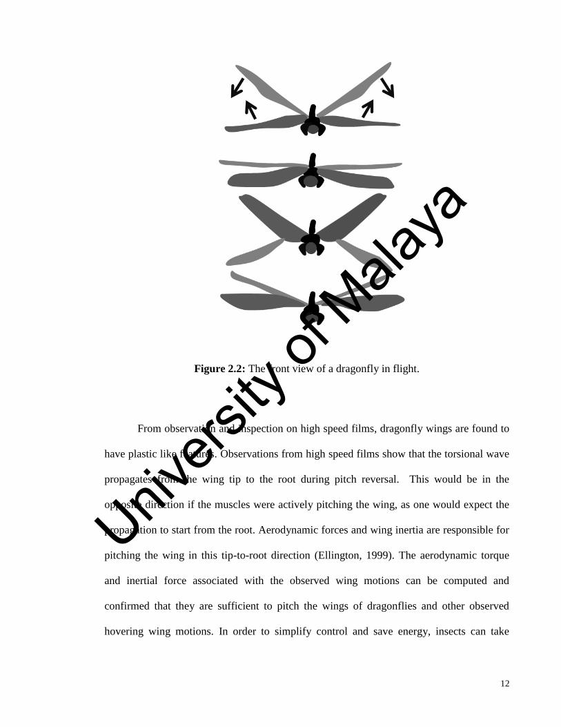
during the down-stroke. The flapping motion of an actual dragonfly is shown in Figure 2.2.
Univers
ity of
Mala
ya
12
Figure 2.2: The front view of a dragonfly in flight.
From observation and inspection on high speed films, dragonfly wings are found to
have plastic like features. Observations from high speed films show that the torsional wave
propagates from the wing tip to the root during pitch reversal. This would be in the
opposite direction if the muscles were actively pitching the wing, as one would expect the
propagation to start from the root. Aerodynamic forces and wing inertia are responsible for
pitching the wing in this tip-to-root direction (Ellington, 1999). The aerodynamic torque
and inertial force associated with the observed wing motions can be computed and
confirmed that they are sufficient to pitch the wings of dragonflies and other observed
hovering wing motions. In order to simplify control and save energy, insects can take
Univers
ity of
Mala
ya
13
advantage of the natural swinging motion near the end of its wing stroke (Lehman et al,
2005).
Dragonflies have a very respectable power to weight ratio. (The dragonfly has a
mass of less than 0.028 kg and can reach a speed of 1.6 km/h). This allows them to
accelerate up to 4g in a straight line and up to 9g in turns. This has been documented in
high speed videotapes of free-flying dragonflies as they pursue prospective prey or when
trying to break off attacks. The agility of a dragonfly is the reason it gets much interest
from BMAV researchers (Luttgess, 1989).
A dragonfly achieves efficient structural performance because of the variations on
its wing pattern. Its ability to withstand deformation can be attributed to the wings
flexibility and stiffness. The highly corrugated wing pattern structure is made up of
quadrilateral, pentagonal, and hexagonal shapes. Studies have shown that these wing
patterns promote rigidity and flexibility along the span of the wing allowing for efficient
use of energy required for flight. Conclusions generated by Maybury et al. (2004) are: The
wing patterns in general follow the tensile forces exhibited on the wing and the variation in
shape determines the amount of flexibility and stiffness in that specific area of the wing
For an example, the more rigid and stiff portions of the wing are the quadrilateral
shaped areas, while the more compartmentalized hexagonal areas are regions where
bending and swaying take place (Figure 3.1). Also, the degrees at which cells are free to
bend are determined by the connections between the cells. Two main types of joints occur
in the dragonfly wings, mobile and immobile. Some longitudinal veins are elastically
joined with cross veins, whereas other longitudinal veins are firmly joined with cross veins.
Scanning electron microscopy reveals a range of flexible cross-vein and main-vein
junctions in the wing, which allows local deformations to occur (Miller et al. 2004). The
Univers
ity of
Mala
ya

14
occurrence of resilin, a rubber-like protein, in mobile joints enables the automatic twisting
mechanism of the leading edge (Akira et al. 1988).
2.4 Biomimetic Micro Aerial Vehicles (BMAVs)
BMAV are micro or nano-scaled aerial vehicles. These vehicles are biologically-
inspired from flying insects, birds and bats to achieve lift and thrust by flapping their
wings. BMAV are lightweight and highly maneuverable. They are capable of flying in
confined areas, rubbles and even indoors. The flapping wings are able to produce a much
larger lift compared to a fixed wing. There are many technical challenges involved with
designing BMAV such as modelling and unsteady aerodynamics, compact flapping
mechanisms, ultra-lightweight materials and structures and importantly an ultra-lightweight
power supply. Because of all these factors, there are currently no operational BMAVs but
only research based prototypes. Researchers from Delft University of Technology have
published numerous articles on their BMAV called Delfly (Tu Delft, 2009). This BMAV
only weighs 3 g, and a wing span of 10 cm.
Figure 2.3. Delfly from TuDelft
There are numerous articles published on BMAVs. Various categories are studied
under the BMAV field which includes aerodynamics (47%), propulsion and mechanisms
Univers
ity of
Mala
ya

15
(22%), system design and guidance and control contributes 11% and the studies of
structures and materials which is 9% of the total. An ultra-light weight, micro-sized
mechanism and power supply to enable free flight is the most challenging task in
developing a BMAV. Madangopal et al. (2005) analyzed the energetics of a BMAV design
with a four-bar flapping mechanism. Conn et al. (2007) created a parallel crank-rocker
mechanism that allows unconstrained, integrated flapping and pitching motion. Bolsman et
al. (2009) created an actuation mechanism that reduces energy expenditure and amplifies
flapping amplitude. Guo et al. (2012) created an actuated flapping wing rotor model using
an piezoelectric actuator and did a comparison with their numerical model simulation.
The structures and materials of BMAV are often inspired from flying organisms,
such as insects or birds or even bats. Song et al. (2004) made a comprehensive analysis on
the mechanical properties of the forewing of the cicada. This serves as a baseline for
BMAV materials. Dirks and Taylor (2012) showed that the cross veins of a locust wing
provides a barrier against crack propagations. A simplified insect wing model (inspired by
a dragonfly) was modeled by Sivasankaran and Ward (2015) based on spatial networking
analysis. Rubentheren et al. (2015) produced a chitosan membrane to biomimic a dragonfly
wing membrane and applied them to simplified wing frame structures.
2.5 Fabrication of artificial insect wings
Hisayoshi et al. (2014) measured the first natural frequency and the passive
deformation of a dragonfly wing. An artificial wing that exhibited the same characteristic
was fabricated and the first natural frequency was found to be 120 Hz. This proves that the
dragonfly wing does not flap at its natural frequency to avoid resonance effect. Previously,
researchers concluded that dragonfly wings flap at their natural frequency to conserve
energy (Seiichi et al. 2008). The wing beat frequency of a flapping dragonfly is 30 Hz.
Univers
ity of
Mala
ya
16
There is a twist at the nodus of the natural wing which increasingly deforms from the base
to tip. A carbon rod was used to replicate the leading edge. By this, the artificial wing was
able to produce a natural frequency similar to an actual dragonfly wing. The aerodynamic
power created was five times higher in magnitude than a carbon wing. Tanaka (2010)
demonstrated a method to fabricate corrugated artificial insect wings using a hoverfly as a
model. The wing, made of a thermosetting resin, contained veins on a corrugated
membrane. This mimics the wing structure of an actual hoverfly wing. The veins and
membranes are created by a single 3D mold. The molds were created using a layered UV-
laser micro machine.
The surface profile of the fabricated artificial hoverfly wing matched the original
mold. The spanwise stiffness of the artificial wing was 2.2 × 10⁻⁷ Nm−2, which is the
same magnitude of a natural hoverfly wing. This research has managed to produce an
artificial 3D insect wing with micron order precision. Shang (2009) fabricated an artificial
wing with defined static properties that were comparable to a natural wing (first
approximation). The method described by Shang can be modified to accommodate camber
or corrugated profiles. The polydimethylsiloxane (PDMS) mold can be shaped according to
the wing pattern and then cured. Spin-coating can be used to allow free flow of the mold
onto the venation pattern (although other methods are allowed as well). PDMS or another
appropriate polymer can be chosen as a membrane. Etching will further aid in the
distribution in a confined area. This can also aid in introducing complex folds and flexion
lines just like a biological wing. Dynamic bending and stiffness will be greatly affected by
wing mass disproportionality. Since the venation pattern correlates with mass distribution,
it is likely that biologically inspired artificial wings can be optimized to exhibit the
dynamic properties found in real dragonfly wings. Francis et al. (2001) have fabricated a
MEMS polymer structure which integrates the thorax, two wings, and a tergum. These
Univers
ity of
Mala
ya

17
parts were connected with a non-integrated actuator. Based on the experimental results and
observation, it was shown that this structure is able to adequately mimic the flexures and
twist of real wing motion.
2.6 Frequencies of insect wings
Several studies have been done to find the flapping and natural frequencies of flying
insects. Ngoc et al. (2013) conducted experiments to compare the natural frequencies of an
actual beetle hind-wing and an artificial wing which biomimics it. Both of these wings
were subjected to dynamic vibrations to measure resonance frequencies. The wing mass
was measured by an electronic balance. A total of 29 points on an actual beetle hind-wing
and 25 points on the fabricated artificial wing were painted to aid the laser sensor in
measuring the deflection of the wing. The recorded frequencies of beetle hind wing were
47.5 Hz, 88 Hz, and 176 Hz, respectively. Since the flapping frequency of a beetle ranges
from 35 to 40 Hz, it was assumed that the higher mode shape would have little effect on the
shape of the wing (deformation). Additionally, Ngoc et al. 2013, studied the relationship of
eight different insect species. The wingbeat frequency of these flying insects was measured
using a high-speed camera (imaging technique) while the natural frequency was determined
using a laser displacement sensor. Ngoc found that there is a prominent ratio between
wingbeat frequency and natural frequency. This ratio is 0.12-0.67 for insects flapping less
than 100 Hz and 1.22 for those with higher wingbeat frequencies. These findings suggest
that these frequencies do correlate with each other.
2.7 Static test conducted on real and artificial insect wings
Univers
ity of
Mala
ya

18
Rajabi et al. (2011) performed a detailed study on dragonfly wings using SEM.
These images are used to study the morphology and microstructure of an actual dragonfly
wing. A micro tensile tester was used to study the mechanical behaviors of the wing. An
overall observation shows that the wings have a highly corrugated structure. This is
believed to increase the overall stiffness of the wing and possibly prevent initial crack and
tear. This indirectly provides a tough barrier to the wing (preventing crack propagation by
closing the crack tip). The critical region of the wing is the nodus. The corrugations also
provide a high load bearing capacity and flexibility. The hollow shaped tubules can be
assumed to provide a high fatigue resistance especially when the wings are subjected to
dynamic loadings (flapping motion). They also increase the flexibility of the wing
structure, thereby affecting its fatigue resistance. Rajabi presents the fracture strains
obtained as a percentage value whereby the forewing and hindwing values are 5.65% and
5.58%, respectively.
Song et al. (2004) tested longitudinal veins (costa and radius) extracted from four
damselflies and tested in a micro-tensile machine. The specimens were held with a special
paper frame. The specimens were classified into two categories: fresh and dry. The average
tensile strength of the actual (fresh) and dry costa are 251 MPa, and 232 MPa. The average
modulus value for the actual (fresh) and dry costa are 14.37 GPa, and 14.43 GPa,
respectively. These values are found to be essentially the same which shows that aging
does not give any significant impact on tensile properties (costa was left to dry for a year).
The average tensile strength of fresh (actual) and dry radius are 285 MPa and 278 MPa.
The modulus of an actual (fresh) radius and dry radius are 16.87 GPa, and 14.89 GPa,
respectively.
2.8 Flapping mechanism
Univers
ity of
Mala
ya

19
Francis et al (2001) proposes a novel micro flying machine concept based on
MEMS technologies, which could potentially perform ascending, linear movement and
rotation. The principal advantage of using such technologies is that the solutions proposed
in the design process can be easily scaled down. The first step involves studying the
feasibility of design and machining a type of stainless steel artificial wing. Few flying
insects (weighing 1 gram) are able to flap their wings which have dimensions in the range
of 10mm to 30 mm. These insects flap with a frequency of 20 Hz to 150Hz. Secondly, a
linear electromagnetic actuator was proposed to excite the wings. Usage of the actuator has
proven advantageous as the excitation frequency can be adapted to the wing resonance
frequency. In the near future as proposed by the authors, a simple control mechanism can
be integrated to control the mechanism by having different oscillations on both sides (right
and left) without modifying the original mechanism. There should be more research done
focusing on the improvisation of the flapping mechanism.
Univers
ity of
Mala
ya

20
CHAPTER 3: RESEARCH METHODOLOGY
3.1 Introduction
This chapter introduces the methods employed to conduct the experiments and
simulations in this research project. It is ordered as follows: wing model overview,
topological optimization, method and types of analysis used, wing frame fabrication
process, static stress experiments, the flapping mechanism and the high speed imaging
technique set up.
3.2 Wing model overview
The dragonfly species used in this study is called Diplacodes Bipunctata. This
species has a distinct red discoloration with a wing span and body length of approximately
0.055 m and 0.035 m, respectively. A digital image (resolution 1600 dpi) was taken of this
dragonfly using a Nikon D7000 camera (Figure 3.1). Both the fore and hind wings were
modeled from this digital image.
Univers
ity of
Mala
ya

21
Figure. 3.1 Main parts of a dragonfly wing
a) Radial ; b) Costa- leading edge (rectangular pattern throughout) the stiffest pattern of all
parts; c) Nodus (part of the vein which is much thicker than the others, plays a pivotal role
in the dissipation and storage of mechanical energy); d) Pterostigma (behaves as a
dampener);
e) Anal margin and supercosta; f) Small hexagonal patterns which are compactly arranged
ranging from 0.0001 to 0.0002 m in size; g) Large quadrilateral and hexagonal patterns
ranging from 0.0002 to 0.0004 m in size. 1-15) Dragonfly wing patterns that are divided
into several regions for further study.
Univers
ity of
Mala
ya

22
3.3 Spatial network analysis
Spatial network analysis as mentioned in Chapter 2 is a graphical topological
optimization method that is used in various fields involved with geographical maps. A
spatial network (sometimes also called geometric graph) is a graph in which the vertices or
edges define spatial elements associated with geometric objects, which means the nodes are
located in a space within a specified unit (e.g. radius or distance). There are various
methods of conducting spatial network analysis. Geographical Information Systems used
this method to explore geographic spatial patterns (Angel, 2010). Our methodology is
similar, but we are applying this algorithm (based on shape, angle and density) to a
biological structure (a dragonfly wing). The idea of simplifying a dragonfly wing based on
spatial network analysis was inspired by observing its compactly arranged geometrical
patterns. Although there are a variety of methods available to conduct a spatial network
analysis, the proximity proposition method was chosen for this analysis because of its
conformity of use to a wing structure. The proximity proposition states that among all
shapes available, the circle has the shortest average distance to its center (Angel, 2010).
Since there are many possible centers for a known shape, it is essential to define at least
one appropriate center of a shape before defining a Proximity Index: The Proximate Centre
is defined as the center of gravity of a shape. The Proximity Index: ratio of the average
distance from all points in the equal-area circle center: average distance to the Proximate
Centre from all points in the shape.
Frolov (1975) computed that the mean distance to the centre of a circle is equal to two
thirds of its radius and suggested that it would be quite accurate to be used as a measure of
compactness. The Proximity Index therefore uses Frolov’s equation. In our case, this new
approach is initiated due to the fact that after close observations, it could be noted that the
Univers
ity of
Mala
ya
23
3.3.1 Canny edge detection algorithm
The image was imported into Matlab and segmented using the Canny edge
detection algorithm, resulting in a logical image illustrated with point clouds. This
grayscale image was then smoothed with a Gaussian filter to suppress noise. The main
vein structures were manually traced out and divided into sections using splines and
polygons. An edge detection algorithm was required to define the different regions
separated by veins in the image of the wing. The Canny edge detection algorithm is one of
the most popular algorithms, because of its detection of edge at a low error rate. The
algorithm runs in five steps which are:
1) Using Gaussian filter to smooth the image and remove noise;
All camera digital images will possess some amount of noise (blurry lines or edges,
dots, etc). Noise must be reduced to avoid errors caused by wrongly assuming the noise as
a part of the edge. This is an essential first step for Canny edge detection algorithm. The
image must then be smoothed using a Gaussian filter. The filter is applied using a matrix
quadrant as shown in (1) below:
1
𝑥 ||
𝑎 𝑏 𝑐 𝑏 𝑎𝑏 𝑑 𝑒 𝑑 𝑏𝑐 𝑒 𝑓 𝑒 𝑐𝑏 𝑑 𝑒 𝑑 𝑏𝑎 𝑏 𝑐 𝑏 𝑎
|| (3.1)
2) Edges are detected where the computed intensity gradients are the largest;
The Canny algorithm finds edges where the grayscale intensity of the image
changes the most. These areas are found by determining pixel gradients in the image.
Sobel-operator (feature detection filter in Matlab) is applied to determine the pixel
gradients in the smoothed image. Gradients are approximated in the x- and y-directions by
applying the kernels shown in (3.2) and (3.3). In these equations 𝐾𝐺𝑋 and 𝐾𝐺𝑌 represent
the kernel
Univers
ity of
Mala
ya
24
matrices and a and b are unknowns;
𝐾𝐺𝑋
= |−𝑎 0 𝑎−𝑏 0 𝑏−𝑎 0 𝑎
| (3.2)
𝐾𝐺𝑌 = |𝑎 𝑏 𝑎0 0 0
−𝑎 −𝑏 −𝑎| (3.3)
The strongest edges can then be assumed as an Euclidean distance. This can be measured
by applying the law of Pythagoras. It can also be simplified by applying Manhattan
distance formula as shown in Equation 3.2. The Euclidean distance value is then applied to
the image. The computed edge stresss are then compared to the smoothed image;
|𝐺| = √𝐺𝑥2 + 𝐺𝑦
2 (3.4)
where Gx and Gy are the gradients in the x- and y-directions respectively.
Equation 3.5 shows the method to determine the direction of the edges.
𝜃 = arctan (|𝐺𝑦|
|𝐺𝑥|) (3.5)
3) Local maxima are marked as edges;
The blurred edges are converted to sharp edges in this step. The highest value (maximum)
gradient is preserved and the others are deleted. The algorithm for each pixel in the gradient
image is outlined below:
1. Convert or round all the nearest θ (gradient) to the nearest 45◦.
2. The edge stress of the current pixel in both positive and negative directions are
compared. For example, if the gradient direction is north (90◦), compare with the pixels to
the north and south.
Univers
ity of
Mala
ya

25
3. Check to see that the edge stress of the current pixel is the largest. If not, remove the
value.
4) Use double threshold to detect potential edges;
The non-maximum values of the gradients may be the true edges of the image but
they were not strong due to the large effect of noise or color variation. The simplest way to
distinguish them is to use a threshold. The Canny edge detection algorithm uses a double
thresholding method (Matlab)
5) Track edges via hysterisis whereby final edges are determined by suppressing all non-
connected edges to a prominent edge.
Strong edges can immediately be included in the final edge image. Even if there is a
lot of noise interference, this noise will not be strong enough to mask strong edges. (for
threshold levels that are properly adjusted). Weak edges are included if they are deemed to
be a part of the true image and only if they are connected to strong edges. BLOB-analysis
(Binary Large Object) was used for edge tracking. This preserves strong edges are
preserved while suppressing weak edges.
3.3.2 Proximity index
The smaller vein structures were then modeled, in a similar way, to match the
detailed patterns and densities shown in the logical image. The spatial network analysis
method (proximity index) was employed to perform the segmentations. Although there are
a variety of methods available to conduct a spatial nework analysis, the proximity
proposition method was chosen for this analysis because of its conformity of use to a wing
structure. A circle is the most compact geometric shape possible, so this was selected as a
reference defining the specified unit (radius) (de Smith et al. 2007). The proximity
Univers
ity of
Mala
ya

26
proposition is defined as the shortest average distance of a circle in a given area of
symmetrical shapes. The proximity index is the ratio of the proximate center from all points
in the shape. Where (xi, yi) are the coordinates of a particular node (i), n is the total number
of nodes, and (xc, yc) are the fixed coordinates of bref (point of reference).
The mean distance (dCA) of any point bounded by the circle (of radius RA) to its center is
given in Eq. 7( de Smith et al. 2007):
𝑑𝐶𝐴 =1
𝜋𝑅2 ∫ 2𝜋𝑟2𝑅𝐴
0𝑑𝑟 =
2
3𝑅𝐴 (3.7)
Since
𝑅𝐴 = √𝐴 𝜋⁄ (3.8)
Where A is the area of the proximity circle
Therefore:
𝑑𝐶𝐴 =2√(𝐴 𝜋⁄ )
3 (3.9)
The proximity index (Iy) is the ratio of the proximate center from all points in the shape.
The 𝑑𝐶𝑆 is the radius of the circle. The equation for calculating the proximity index can be
written as:
𝐼𝑦 =𝑑𝐶𝐴
𝑑𝐶𝑆=
2√(𝐴 𝜋⁄ )
3𝑑𝐶𝑆 (3.10)
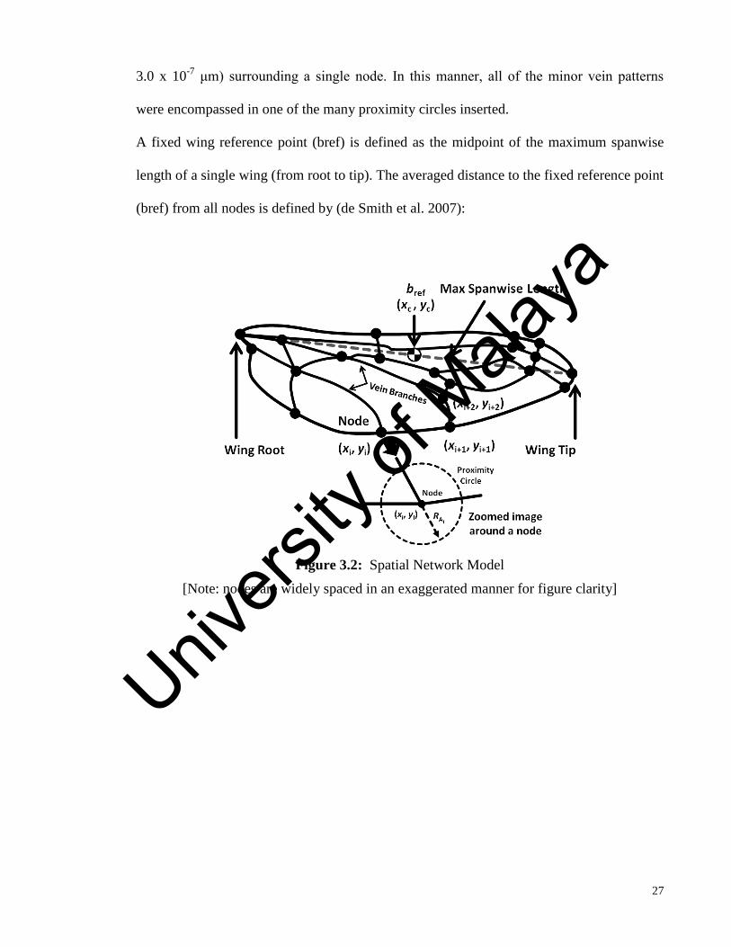
Nodes were manually placed at the vein structure intersections on the dragonfly wing
model selected for biomimicry (Figure 3.2). The nodes were only placed on intersections of
veins that are 3.0 x 10⁻⁷
μm thick or lesser. Each circle was manually sized to be the
minimum radius required to encompass all of the minor vein patterns (thickness less than
Univers
ity of
Mala
ya
27
3.0 x 10⁻⁷
μm) surrounding a single node. In this manner, all of the minor vein patterns
were encompassed in one of the many proximity circles inserted.
A fixed wing reference point (bref) is defined as the midpoint of the maximum spanwise
length of a single wing (from root to tip). The averaged distance to the fixed reference point
(bref) from all nodes is defined by (de Smith et al. 2007):
Figure 3.2: Spatial Network Model
[Note: nodes are widely spaced in an exaggerated manner for figure clarity]
Univers
ity of
Mala
ya
28
3.3.3 CAD model
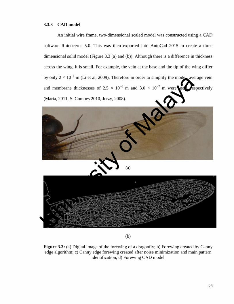
An initial wire frame, two-dimensional scaled model was constructed using a CAD
software Rhinoceros 5.0. This was then exported into AutoCad 2015 to create a three
dimensional solid model (Figure 3.3 (a) and (b)). Although there is a difference in thickness
across the wing, it is small. For example, the vein at the base and the tip of the wing differ
by only 2 × 10⁻⁶
m (Li et al, 2009). Therefore in order to simplify the model, average vein
and membrane thicknesses of 2.5 × 10⁻⁶
m and 3.0 × 10⁻⁷
m were used, respectively
(Maria, 2011, S. Combes 2010, Jerzy, 2008).
(a)
(b)
Figure 3.3: (a) Digital image of the forewing of a dragonfly; b) Forewing created by Canny
edge algorithm; c) Canny edge forewing created after noise minimization and main pattern
identification; d) Forewing CAD model
Univers
ity of
Mala
ya

29
(c)
(d)
Figure 3.3: (continued) a) digital image of the forewing of a dragonfly; b) forewing
created by Canny edge algorithm; c) Canny edge forewing created after noise minimization
and main pattern identification; d) forewing CAD model
3.4 Finite element analysis (FEA)
FEA or more commonly known finite element analysis modeling follows three
general rules: pre-processing, analysis and post processing. Equation (3.11) is a general
structural equation (Bucalem, 1997):
|M| Ü + |C|u + |K|u= F cos (At + r) (3.11)
Univers
ity of
Mala
ya

30
Where |M| is the mass matrix, Ü is the acceleration, C is the damping matrix, K is the
stiffness matrix and F is the force vector. The software shall assemble the matrix equation
of the structure. The first part would be to solve the matrix equation below:
|M| Ü + |K|u = 0 (3.12)
This equation was used to solve the free vibrations of structure. The solution to the
equation above gives the natural frequencies (eigenvalues) and the undamped mode shapes
(eigenvectors). These are the parameters needed to define the basic dynamical properties of
a structure. Since, the main focus is natural frequency, which is a dynamic response, these
values are needed in subsequent analysis for dynamic displacements and stresses. For
harmonic motions:
U ̈= -ω^2 u (3.13)
In this equation ω is circular frequency. Substituting equation (3.14) into equation (3.13)
gives the matrix eigenvalue expression of:
|K|-1 = |M| u = |I| u (3.14)
In this equation |I| is the identity matrix. The back substitution method is used to obtain the
corresponding matrix of eigenvectors |Ҩ|. The matrix equation of motion for the structure
contains off-diagonal terms. The matrix equation may be deduced by introducing the
following transformation:
u = |Ҩ| x (3.15)
and writing the following expressions:
Univers
ity of
Mala
ya
31
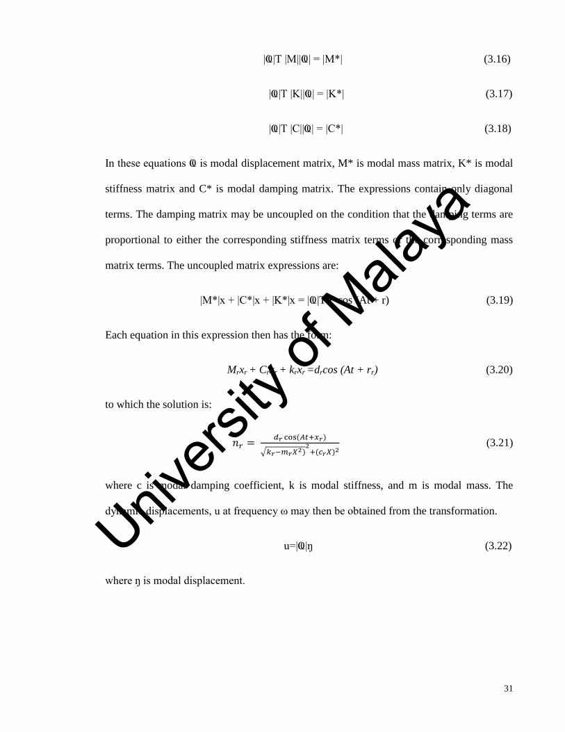
|Ҩ|T |M||Ҩ| = |M*| (3.16)
|Ҩ|T |K||Ҩ| = |K*| (3.17)
|Ҩ|T |C||Ҩ| = |C*| (3.18)
In these equations Ҩ is modal displacement matrix, M* is modal mass matrix, K* is modal
stiffness matrix and C* is modal damping matrix. The expressions contain only diagonal
terms. The damping matrix may be uncoupled on the condition that the damping terms are
proportional to either the corresponding stiffness matrix terms or the corresponding mass
matrix terms. The uncoupled matrix expressions are:
|M*|x + |C*|x + |K*|x = |Ҩ|T F cos (At + r) (3.19)
Each equation in this expression then has the form:
Mrxr + Crxr + krxr =drcos (At + rr) (3.20)
to which the solution is:
𝑛𝑟 = 𝑑𝑟 cos(𝐴𝑡+𝑥𝑟)
√𝑘𝑟−𝑚𝑟𝑋2)2
+(𝑐𝑟𝑋)2 (3.21)
where c is modal damping coefficient, k is modal stiffness, and m is modal mass. The
dynamic displacements, u at frequency ω may then be obtained from the transformation.
u=|Ҩ|ŋ (3.22)
where ŋ is modal displacement.
Univers
ity of
Mala
ya

32
3.4.1 Element and mesh
The purpose of building an Autodesk model was to calculate the natural frequency
and displacement of the wing under a load. The mesh sizes of the elements were viewed
visually to ensure the mesh distribution was fine throughout the structure. The mesh was
chosen based on the results of a grid study. A grid study was performed to determine the
mesh size required for accurate results. The program was run with both coarse and fine
grids, with mesh sizes of 0.001 m and 0.0001 m respectively. The difference in results
between the coarse mesh and a fine mesh was found to be less than 2%. However, a
comparison of the run times of these mesh sizes was 70 % faster for the detailed model and
50% faster for the simplified models. (4 hours for detailed and 2 hours for simplified in the
former mesh size). Therefore a mesh size of 0.001 m was used for all subsequent runs.
Shell based elements are often used in finite element analysis models to calculate
the displacement. Each element in this model was specified as a shell, in order to simulate
the highly efficient load bearing capabilities of an insect wing (Jiyu et al, 2012, Combes,
2010, Tu Delft, 2013, Du Mont, 2009). Teflon was specified as the material for each shell.
This is because past research has identified Teflon as possessing similar characteristics to a
real dragonfly wing (made up of chitin and chitosan) (Antonia et al, 1998). The model is
assumed to have identical material properties in all directions with a single modulus of
elasticity and Poisson Ratio value. The properties are summarized in Table 3.1.
Table 3.1: Properties of Teflon
Density 1260 kg/m3
Modulus of elasticity 6.0 GN/m2
Poisson’s ratio 0.25
Univers
ity of
Mala
ya
33
Autodesk’s Algebraic Iterative Multi-Grid Scheme, with a third order Newton
Raphson integration method, was used as the finite element solver. A general element
formulation was selected, because this provides a robust solution for thin and thick
elements. This was necessary because the wing model is designed with two different type
of thickness (vein and membrane). The analysis formulation is set to nonlinear for natural
frequency analysis and linear for static stress analysis. The shell element model is set to be
isotropic, as it is assumed that the parts will only experience deflection in the elastic region
of the material.
3.4.2 Modal analysis: Mode shapes and MAC
A fixed constraint was placed at the base of the wing. This mimics a real dragonfly
which flaps with a fixed joint at the base. The modal analysis computes the natural
frequencies, mode shapes, the |M|, |C| and the response analysis matrices. Ten modes of
interest were computed in this experiment. The cut-off frequency was set to 100Hz as a
constraint for the simulation results. A lumped mass representation is used with an
allocated ratio of 0.2 percentage of data storage (S. Combes, 2003).
Correlation analysis of the similar mode shapes between the detailed and simplified
model were carried out. MAC (Modal assurance criterion) requires mode shape data from
two similar modes of the structure. Due to the large size of the finite element models in
terms of their number of nodes, it is not practically possible to include all the nodes into
analysis. Therefore 30 nodes were chosen, along the center of the wing span, at an interval
of 0.0002 m (distance between each node) were chosen as the representative of the mode
shape. The modal assurance criterion was calculated based on the mode shapes obtained
from the simulation results which will be discussed in Chapter 3. Mode was calculated
Univers
ity of
Mala
ya
34
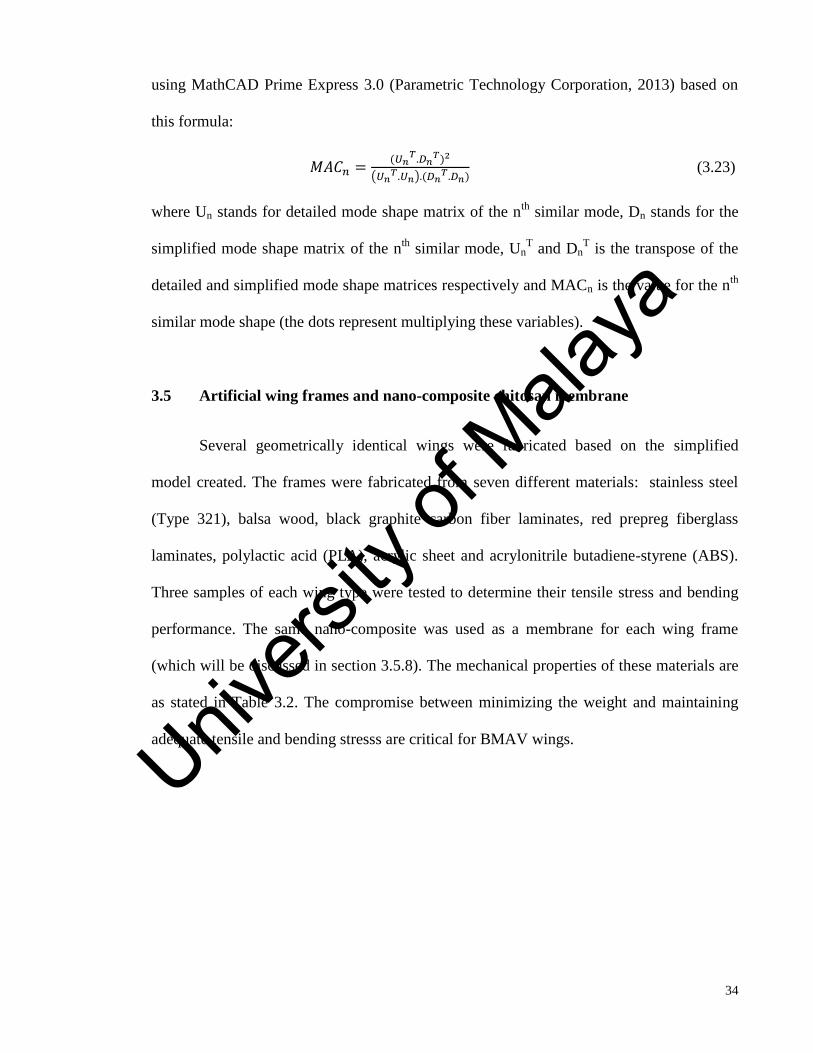
using MathCAD Prime Express 3.0 (Parametric Technology Corporation, 2013) based on
this formula:
𝑀𝐴𝐶𝑛 =(𝑈𝑛
𝑇.𝐷𝑛𝑇)2
(𝑈𝑛𝑇.𝑈𝑛).(𝐷𝑛
𝑇.𝐷𝑛) (3.23)
where Un stands for detailed mode shape matrix of the nth
similar mode, Dn stands for the
simplified mode shape matrix of the nth
similar mode, UnT and Dn
T is the transpose of the
detailed and simplified mode shape matrices respectively and MACn is the value for the nth
similar mode shape (the dots represent multiplying these variables).
3.5 Artificial wing frames and nano-composite chitosan membrane
Several geometrically identical wings were fabricated based on the simplified
model created. The frames were fabricated from seven different materials: stainless steel
(Type 321), balsa wood, black graphite carbon fiber laminates, red prepreg fiberglass
laminates, polylactic acid (PLA), acrylic sheet and acrylonitrile butadiene-styrene (ABS).
Three samples of each wing type were tested to determine their tensile stress and bending
performance. The same nano-composite was used as a membrane for each wing frame
(which will be discussed in section 3.5.8). The mechanical properties of these materials are
as stated in Table 3.2. The compromise between minimizing the weight and maintaining
adequate tensile and bending stresss are critical for BMAV wings.
Univers
ity of
Mala
ya

35
Table 3.2: Mechanical properties of frame structure materials (David 2014, D. Akin et al
2014, Arcy, 1961, Shyy, 2010, Rahman, 2012, Marcin, 2011, Boeing, 2003 and 2004,
Borrega, 2015, Da Silva, 2007, Leban, 2013, and Osei, 2014)
Material Density
(kg/m3)
Modulus of
Elasticity
(N/m2)
Poisson
Ratio
Shear
Modulus of
Elasticity
(N/m2)
Thickness
(m)
Stainless steel (Type
321)
7920.0 1.90 x10¹¹
0.3 7.7 x 10¹⁰
0.01
Balsa wood 130.0 3.00 x10⁹
0.5 1.5 x 10⁸
0.02
Black graphite carbon
fiber
1750.0 2.00x10¹¹
0.5 2.4 x 10¹¹
4x10⁻⁴
Red prepreg fiberglass 1522.4 2.00x10¹¹
0.5 3.0 x 10¹⁰
3x10⁻⁴
Polylactic acid (PLA) 1190.0 3.50x10⁹ 0.36 3.37x10
9 2x10
-4
Acrylic 1180.0 3.32x10⁹ 0.35 6.20x10
7 2x10
-4
ABS 1050.0 2.80x10⁹ 0.35 1.03x10
9 2x10
-4
3.5.1 Fabrication of stainless steel (Type 321) wing frames
(a) (b)
Figure 3.4: Stainless steel type 321 wing frames; a) forewing, b) hindwing
Stainless steel (Type 321) is in the high carbon grade category, meaning that it
contains a minimum and maximum of 0.04% and 0.10% carbon, respectively. Higher
carbon helps the material retain stress at extreme temperatures. Type 321 is commonly used
in aircraft applications; because it is low in density (e.g. relative light weight) and high
temperature resistance. In our experiment, the stainless steel was subjected to solution
annealing. This is a common process done to ensure the smoothness of the grain structure.
This means only the carbides which may have precipitated to the grain boundaries are
Univers
ity of
Mala
ya
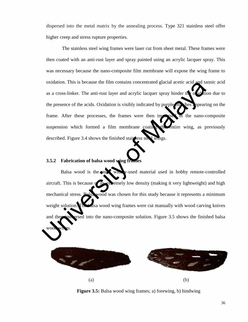
36
dispersed into the metal matrix by the annealing process. Type 321 stainless steel offer
higher creep and stress rupture properties.
The stainless steel wing frames were laser cut from sheet metal. These frames were
then coated with an anti-rust layer and spray painted using an acrylic lacquer spray. This
was necessary because the nano-composite film membrane will expose the wing frame to
oxidation. This is because the film contains concentrated glacial acetic acid and tannic acid
as a cross-linker. The anti-rust layer and acrylic lacquer spray hinder the oxidation due to
the presence of the acids. Oxidation is visibly indicated by purple blotches appearing on the
frame. After these processes, the frames were then immersed in the nano-composite
suspension which formed a film membrane coating the entire wing, as previously
described. Figure 3.4 shows the finished stainless steel wings.
3.5.2 Fabrication of balsa wood wing frames
Balsa wood is the most widely-used material used in hobby remote-controlled
aircraft. This is because of its extremely low density (making it very lightweight) and high
mechanical stress. Balsa wood was chosen for this study because it represents a minimum
weight solution. The balsa wood wing frames were cut manually with wood carving knives
and then immersed into the nano-composite solution. Figure 3.5 shows the finished balsa
wood wings.
(a) (b)
Figure 3.5: Balsa wood wing frames; a) forewing, b) hindwing
Univers
ity of
Mala
ya

37
3.5.3 Fabrication of black graphite carbon fiber wing frames
Black graphite carbon fiber sheets were purchased and visually inspected to make
certain they were uniform in appearance and free from foreign material. The specifications
are listed in Table 3.3.
Table 3.3: Specifications of black graphite carbon fiber
The woven laminate was hardened using an epoxy resin with a hardener (Araldite
rapid kit). Both epoxy resin and hardener were mixed with a ratio of 1:1 and then applied
evenly to the laminate in a thin layer. The laminate was then left to cure in a Memmert
UNB 300 convection oven for about two hours at a constant temperature of 45°C. The
forewing and hindwing shapes were then carved out of the hardened laminates manually
with a knife, using the stainless steel wings as a reference. The only difference between the
black graphite wings and the others, were that the inner gap regions were not carved out
according to the simplified model. Attempts to do so proved impossible, because it resulted
Thickness 0.04 mm
Carbon yarn spacing Four per 0.45 kilograms per strand
Warp tracer weave spacing 0.3 ± 1 m across the fabric width
Fill tracer weave spacing 0.6 ± 1 m apart
Length to diameter ratio (L/D) (See
Figure 3.6)
> 10
Figure 3.6: Waviness of carbon fiber yarns
Univers
ity of
Mala
ya

38
in delamination of the material. However, the overall size and shape of these wings are the
same as the others. Figure 3.7 shows the finished black graphite carbon fiber wings.
3.5.4 Fabrication of red prepreg fiberglass wing frames
Red prepreg fiberglass plies with a thickness of 0.03mm were purchased and
visually inspected. After curing, the red prepreg fiberglass exhibits a plastic-like
characteristic unlike carbon fiber which will retain its strand-like properties. This increases
the chance of delamination if a resin and hardener is not applied. The red prepreg fiberglass
(after curing) does not require an extra application of resin or hardener. In order to create
the wing frame structure, the material was warmed as necessary to enable easier manual
carving with a knife. Figure 3.8 shows the finished red prepreg fiberglass wings.
(a) (b)
Figure 3.8: Red pre-preg fiberglass wing models after immersion in chitosan nano-
composite solutions; a) forewing, b) hindwing
(a) (b)
Figure 3.7: Black graphite carbon fiber wing frames; a) forewing, b) hindwing
Univers
ity of
Mala
ya
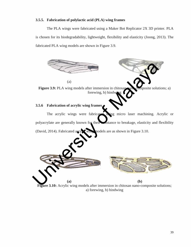
39
3.5.5. Fabrication of polylactic acid (PLA) wing frames
The PLA wings were fabricated using a Maker Bot Replicator 2X 3D printer. PLA
is chosen for its biodegradability, lightweight, flexibility and elasticity (Joong, 2013). The
fabricated PLA wing models are shown in Figure 3.9.
(a) (b)
Figure 3.9: PLA wing models after immersion in chitosan nano-composite solutions; a)
forewing, b) hindwing
3.5.6 Fabrication of acrylic wing frames
The acrylic wings were fabricated using micro laser machining. Acrylic or
polyacrylate are generally known for their resistance to breakage, elasticity and flexibility
(David, 2014). Fabricated acrylic wing models are as shown in Figure 3.10.
(a) (b)
Figure 3.10: Acrylic wing models after immersion in chitosan nano-composite solutions;
a) forewing, b) hindwing
Univers
ity of
Mala
ya
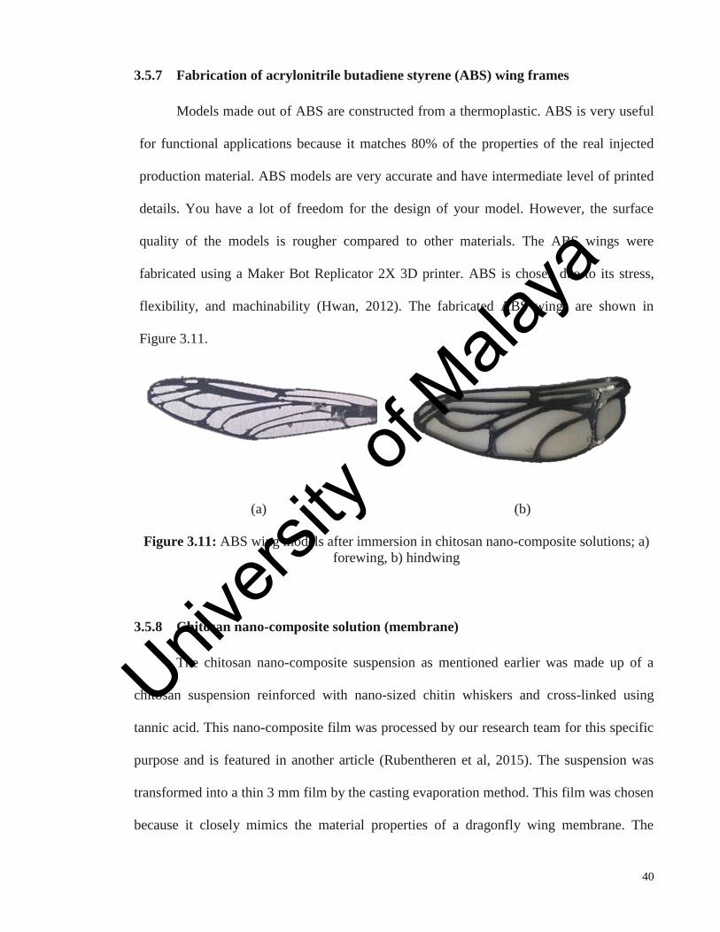
40
3.5.7 Fabrication of acrylonitrile butadiene styrene (ABS) wing frames
Models made out of ABS are constructed from a thermoplastic. ABS is very useful
for functional applications because it matches 80% of the properties of the real injected
production material. ABS models are very accurate and have intermediate level of printed
details. You have a lot of freedom for the design of your model. However, the surface
quality of the models is rougher compared to other materials. The ABS wings were
fabricated using a Maker Bot Replicator 2X 3D printer. ABS is chosen due to its stress,
flexibility, and machinability (Hwan, 2012). The fabricated ABS wings are shown in
Figure 3.11.
(a) (b)
Figure 3.11: ABS wing models after immersion in chitosan nano-composite solutions; a)
forewing, b) hindwing
3.5.8 Chitosan nano-composite solution (membrane)
The chitosan nano-composite suspension as mentioned earlier was made up of a
chitosan suspension reinforced with nano-sized chitin whiskers and cross-linked using
tannic acid. This nano-composite film was processed by our research team for this specific
purpose and is featured in another article (Rubentheren et al, 2015). The suspension was
transformed into a thin 3 mm film by the casting evaporation method. This film was chosen
because it closely mimics the material properties of a dragonfly wing membrane. The
Univers
ity of
Mala
ya
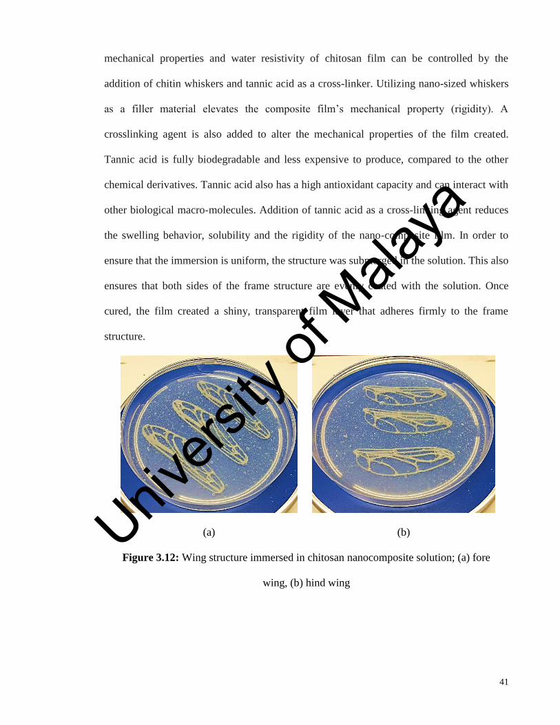
41
mechanical properties and water resistivity of chitosan film can be controlled by the
addition of chitin whiskers and tannic acid as a cross-linker. Utilizing nano-sized whiskers
as a filler material elevates the composite film’s mechanical property (rigidity). A
crosslinking agent is also added to alter the mechanical properties of the film created.
Tannic acid is fully biodegradable and less expensive to produce, compared to the other
chemical derivatives. Tannic acid also has a high antioxidant capacity and can interact with
other biological macro-molecules. Addition of tannic acid as a cross-linking agent reduces
the swelling behavior, solubility and the rigidity of the nano-composite film. In order to
ensure that the immersion is uniform, the structure was submerged in the solution. This also
ensures that both sides of the frame structure are evenly coated with the solution. Once
cured, the film created a shiny, transparent film layer that adheres firmly to the frame
structure.
(a) (b)
Figure 3.12: Wing structure immersed in chitosan nanocomposite solution; (a) fore
wing, (b) hind wing
Univers
ity of
Mala
ya

42
3.6 Numerical Bend-Twist Coupling and Static Stress Simulation Analysis
3.6.1 Numerical bend-twist coupling analysis
The bend-twist coupling is one of the most relevant analyses for a wing cross
section. The effect of the bend-twist coupling appears in a wing structure as a link between
its two deformation states – bending and torsion. A static bend-twist coupling analysis was
performed for further validation of the models created. As previously described, the
analysis was set up with a constraint fixed at the base to mimic an actual dragonfly flapping
mode. Figure 3.13 shows the placement of constraints for a natural frequency analysis
3.6.2 Static stress simulation analysis
A fixed constraint was placed at the base of the wing tip to mimic the hinge of an
actual dragonfly wing. Nodal forces were applied at the tip of the wing to mimic the
tensile and bending test experiments. Simulations were done for all eight wings (forewing
and hindwing fabricated from all four materials). In addition, simulated bending and
tensile tests were done for the frame structures without the membrane to record the effects
of the chitosan nano-composite film on the frame structure. The stresses computed in the
static analysis are used to form the stress-dependent contribution to the tangent-stiffness
Figure 3.13: Placement of constraints fixed in a natural frequency analysis
Univers
ity of
Mala
ya

43
matrix. Static stress analysis, enables the study of stress, strain, displacement, and shear
and axial forces that result from static loading. Figure 3.14 shows the static stress
simulation model for a static stress analysis. Numerical analysis was not constructed until
failure due to the fact that dragonfly wings do not flap until they fail. Hence, a linear
model was used.
Figure 3.14: Constraints for a static stress analysis
3.7 Experimental Set Up
Tensile and bending experimental tests were done on the physical models using the
Instron Universal Testing Machine (Model 5569). Increasing loads were incrementally
applied to the wings until they failed. The data was compiled and integrated by Instron
MERLIN software. A specific jig was designed for both bending and tensile test to clamp
the fabricated models, whereby the slots were used to clamp the thin structures firmly. All
testing was repeated three times for each wing type, necessitating the fabrication of three
identical copies of each wing type. Since the wing frame test specimen is a sheet-like
structure, the same ratio of width-to-gage length (18:18 for forewing and 20:20 for
hindwing) was maintained in order to compensate for the elongation that occurs during
diffuse necking. ASTM test specifications were followed throughout the experiment. Each
base of the wing models were clamped at a fixed point and the tips were clamped at the
Univers
ity of
Mala
ya
44
moving point. The load was then increased gradually with a speed rate of 0.013 m/s. The
rate of extension and the stress-strain curve was observed until the wing model experienced
a structural failure. This point can be observed in the collected data as a sudden decrease in
the load. Data obtained in RAW file (not processed) was then converted to Microsoft Excel
for further analysis. The high speed camera imaging technique was then employed after
close observation of all these seven materials, and three best materials were chosen based
on performances. The main criteria of selection were the ability to withstand high tensile
stress and possess a high compression stress vs strain. Due to the complexity of an actual
dragonfly wing (due to the corrugations and veins) it was impossible to conduct tensile
testing on an actual wing. However, previous research has provided sufficient values to aid
in setting a benchmark for the criteria of the suitable material. Referring to previous
research, the value of tensile and compression stress for an actual dragonfly wing was
found to be 285 MPa and 16.87 GPa, respectively (Rupan et al, 2013). As mentioned
earlier, in order to test the aero-elastic properties of the dragonfly wings, the final step of
the research was two test it on an actual flapping mechanism. This is a static mechanism
which is able to produce a flapping motion frequency up to 250 Hz.
Previous researchers have conducted studies using high speed camera. Gui et al.
(2010) applied simple optical modifications to replace an expensive two-camera system for
taking stereo videos of fire ant alate wingbeat motion. Many have utilized the high speed
camera technique to capture wing motion of birds and insect flights. (Norris 2001; Sudo et
al. 2001, 2005; Dalton 2002; Gorman 2003). Recent advances in high-speed imaging
technique make it possible to capture insect wing motion not only at high phase resolution
but also at high digital resolution, e.g. the Photron Ultima APX high-speed camera used in
our lab is capable of capturing partial frames of 1024256 pixels at 8,000 frames per second
(fps). High digital resolution and high phase resolution together enable a precise analysis of
Univers
ity of
Mala
ya
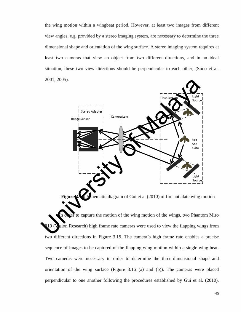
45
the wing motion within a wingbeat period. However, at least two images from different
view angles, e.g. provided by a stereo imaging system, are necessary to determine the three
dimensional shape and orientation of the wing surface. A stereo imaging system requires at
least two cameras that view an object from two different directions, and in an ideal
situation, these two view directions should be perpendicular to each other, (Sudo et al.
2001, 2005).
Figure 3.15: Schematic diagram of Gui et al (2010) of fire ant alate wing motion
In order to capture the motion of the wing motion of the wings, two Phantom Miro
310 (Vision Research) high frame rate cameras were used to view the flapping wings from
two different directions in Figure 3.15. The camera’s high frame rate enables a precise
sequence of images to be captured of the flapping wing motion within a single wing beat.
Two cameras were necessary in order to determine the three-dimensional shape and
orientation of the wing surface (Figure 3.16 (a) and (b)). The cameras were placed
perpendicular to one another following the procedures established by Gui et al. (2010).
Univers
ity of
Mala
ya

46
Both cameras were equipped with a Nikon F lens. A multiple LED lighting system was
used to provide sufficient illumination. Imagery was recorded at a resolution of 320 x 240
pixels and a frame rate of 35000 per second, which allowed the wing beat motion to be
precisely captured. The motion video was stored in a computer via two high speed Ethernet
cables. It was played-back and analyzed using the Vision Research Phantom Camera
Control Software (version 2.6.749.0).
Univers
ity of
Mala
ya

47
(a)
Figure 3.16: (a) Actual experimental set up of the high speed camera imaging
technique, (b) Schematic diagram of the experimental set up
(b)
Figure 3.16: (continued) (a) Actual experimental set up of the high speed camera
imaging technique, (b) schematic diagram of the experimental set up
X 10
Univers
ity of
Mala
ya
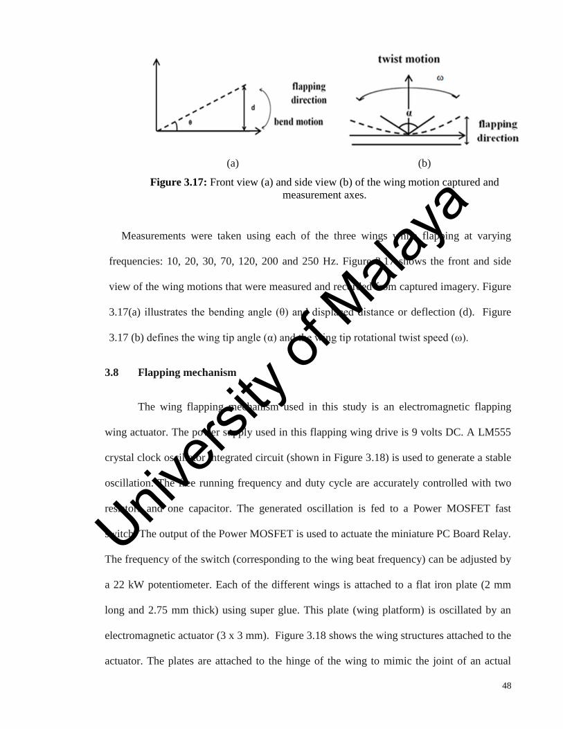
48
(a) (b)
Figure 3.17: Front view (a) and side view (b) of the wing motion captured and
measurement axes.
Measurements were taken using each of the three wings while flapping at varying
frequencies: 10, 20, 30, 70, 120, 200 and 250 Hz. Figure 3.17 shows the front and side
view of the wing motions that were measured and recorded from captured imagery. Figure
3.17(a) illustrates the bending angle (θ) and displaced distance or deflection (d). Figure
3.17 (b) defines the wing tip angle (α) and the wing tip rotational twist speed (ω).
3.8 Flapping mechanism
The wing flapping mechanism used in this study is an electromagnetic flapping
wing actuator. The power supply used in this flapping wing drive is 9 volts DC. A LM555
crystal clock oscillator integrated circuit (shown in Figure 3.18) is used to generate a stable
oscillation. The free running frequency and duty cycle are accurately controlled with two
resistors and one capacitor. The generated oscillation is fed to a Power MOSFET fast
switch. The output of the Power MOSFET is used to actuate the miniature PC Board Relay.
The frequency of the switch (corresponding to the wing beat frequency) can be adjusted by
a 22 kW potentiometer. Each of the different wings is attached to a flat iron plate (2 mm
long and 2.75 mm thick) using super glue. This plate (wing platform) is oscillated by an
electromagnetic actuator (3 x 3 mm). Figure 3.18 shows the wing structures attached to the
actuator. The plates are attached to the hinge of the wing to mimic the joint of an actual
Univers
ity of
Mala
ya

49
dragonfly. This flapping mechanism is able to create a linear up-down stroke motion at
variable wing beat frequencies, up to a maximum frequency of 250 Hz. The flapping
degree was set to be 60° which corresponds with an actual dragonfly wing flapping angle
during hovering flight (Jane, 2004 and Xinyan, 2008).
Figure 3.18: Flapping mechanism used in this research
Univers
ity of
Mala
ya
50
CHAPTER 4: RESULTS AND DISCUSSION
4.1 Introduction
This chapter includes discussion pertaining to the results obtained. It includes the
simulation results, the experimental results, application of the chosen wings in a flapping
mechanism and the images of this application.
4.2 Simplified model creation
Two models were created for each wing. The first model (or detailed model shown
in Figure 3.3) closely approximates the fine detailed structure of an actual dragonfly wing.
This was built using the Canny edge detection algorithm previously described in Section
3.3.1. Due to its small size and complexity, this model proved to be too difficult to fabricate
using laser micro machining. Therefore a second model (or simplified model) was created
that simplifies the structure into its major constituents, by grouping dense patterns and vein
structures into single regions. Fabricated simplified model examples are shown (Figure
4.1). These samples were laser cut from thin (1 mm thickness) stainless steel sheet metal.
Careful consideration was taken into keeping within machining tolerance, with the
objective of fabricating a wing for a BMAV design in the near future. The ratio of the
quadrilateral, pentagons and hexagons are 10:30:60 based on observation. Therefore,
although the hindwing has a larger area than the forewing, the number of regions created is
justified by considering the ratio of patterns. Examples of dragonfly wing patterns can be
seen in Figures 4.2 (a) and (b). The costal part of the wing consists of several uniformally-
arranged rectangular membrane patterns. These were grouped together in different regions
(consisting of 10 to 15 rectangles per region). There are many small, hexagonal membrane
patterns at the anal margin and wing tip. These were grouped into several regions
(consisting of 30 to 50 patterns per region). Table 4.1 shows a summary comparing the
pattern densities of the detailed and simplified models.
Univers
ity of
Mala
ya

51
(a)
(b)
Figure 4.1: Fabricated simplified model (a) Forewing; (b) Hindwing
Table 4.1: Model specifications in terms of number of membranes, density and patterns
The spatial network analysis method was implemented by dividing the wing model
into circles with diameters of 0.00025m and 0.0005 m, for smaller and larger regions
respectively. The size of regions correspond to the pattern density in that particular area.
Smaller regions are used in higher density areas. The center of the circle was determined by
looking at the starting point of a branch of the main vein. Previous research was used as a
reference to determine the center of the circle (HuaiHui et al. 2013).
CAD model Properties
No. membrane
regions
Area ( m2
) Average pattern
density
(region/m2)
Forewing Hindwing Forewing Hindwing Forewing Hindwing
Detailed
Model
787 900 0.00055 0.000577 14309 15517
Simplified
Model
17 16 0.00055 0.000577 30900 27586
Univers
ity of
Mala
ya

52
(a)
(b)
Figure 4.2: Typical dragonfly wing membrane pattern arrangement
Figures 4.2 (a) and (b) shows membrane patterns that are typical of dragonfly
wings. A number of proximate cells are located between two main veins and arranged in
one row to form quadrilateral shapes. Sometimes there are two rows of cells, intercalated
between a pair of main veins. As shown in Figure. 4.2 (b) in this case, one row will fit into
another at an angle of 120° as a result of coequal tension, but both cells are at right angles
when it meets the main vein as in the former case. For numerous rows of cells, all the
angles between them tend to be co-equal angles of 120°, and hence the cells resolve into a
hexagonal or polygonal meshwork. The cell arrangement in dragonfly wings was explained
through soap bubble experiment (Arcy,1961). When four soap bubbles meet in a plane,
they arrange in symmetrical ways either with four or five partition-walls intersecting at
right angles. Five partition walls are known to be unstable. The point where the patterns
branch into four to five patterns was determined to be the center of the circle. The hindwing
of a dragonfly is slightly broader in size compared to the forewing, but the pattern it
comprises remains the same (e.g. quadrilateral, pentagons and hexagons). The number of
patterns that make a region is therefore drawn by observation with the appropriate ratio
(10:30:60) applied to it.
Figure 3.2 in the previous section, shows how the circles were placed on the
detailed model in order to formulate what will become the simplified model. The nodes
(that determine the center of each proximity circle) were placed at branching points,
according to the soap bubble theory. A past article reports that a good index value should
Univers
ity of
Mala
ya
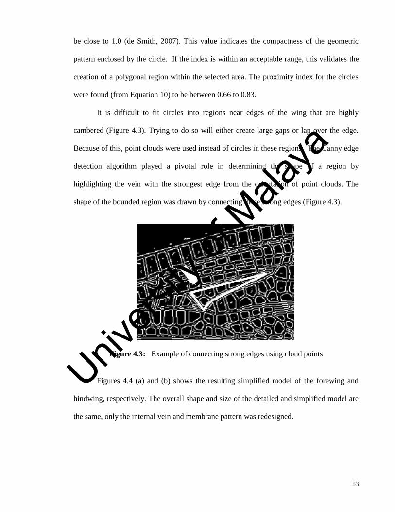
53
be close to 1.0 (de Smith, 2007). This value indicates the compactness of the geometric
pattern enclosed by the circle. If the index is within an acceptable range, this validates the
creation of a polygonal region within the selected area. The proximity index for the circles
were found (from Equation 10) to be between 0.66 to 0.83.
It is difficult to fit circles into regions near edges of the wing that are highly
cambered (Figure 4.3). Trying to do so will either create large gaps or lap over the edge.
Because of this, point clouds were used instead of circles in these regions. The Canny edge
detection algorithm played a pivotal role in determining the shape of a region by
highlighting the vein with the strongest edge from the orientation of point clouds. The
shape of the bounded region was drawn by connecting these strong edges (Figure 4.3).
Figure 4.3: Example of connecting strong edges using cloud points
Figures 4.4 (a) and (b) shows the resulting simplified model of the forewing and
hindwing, respectively. The overall shape and size of the detailed and simplified model are
the same, only the internal vein and membrane pattern was redesigned.
Univers
ity of
Mala
ya

54
4.3 Mode shape analysis and MAC
The mode shape similarities are shown in Figures 4.5 and 4.6. Out of ten mode
shapes computed, the five best matching mode shapes were selected and compared between
these two models. The modes were distinguished by the deflection shape of the structure.
Higher mode shapes were included because these mode shapes will be able to determine
the flutter speed in future work. Therefore Figures 4.5 and 4.6 also include the higher mode
shape comparison. The natural modal frequencies were also listed in Figures 4.5 and 4.6. It
is known from the structural dynamics that natural frequency is directly proportional to the
square root of the stiffness and inversely proportional to square root of the mass. Due to the
minimization of patterns (reduction of number of regions), the overall mass has been
minimized with the detailed model having a mass of 0.0216 kg and the simplified model
having a mass of 0.0182 kg. This reduction has been achieved by utilizing spatial network
analysis. Minimization of mass and reduction in stiffness will result in an increase of
natural frequency and the results shows a good agreement with this. The increase in natural
frequency was in the range of 3-10% for all simplified models.
(a) (b)
Figure 4.4: Simplified models, (a) forewing, (b) hindwing
Univers
ity of
Mala
ya

55
f= 21.1 Hz f= 22.2 Hz
Mode 2 Mode 1
(a)
f = 39.9 Hz f = 41.9 Hz
Mode 3 Mode 2
(b)
f = 59.1 Hz f = 61.1 Hz
Mode 5 Mode 6
(c)
f = 68.3 Hz f = 73.7 Hz
Mode 6 Mode 5
(d)
f = 94.6 Hz f = 99.9 Hz
Mode 8 Mode 8
(e)
Figure 4.5:Mode shapes and corresponding natural frequencies for both detailed (left) and
simplified models (right) : forewing
Univers
ity of
Mala
ya
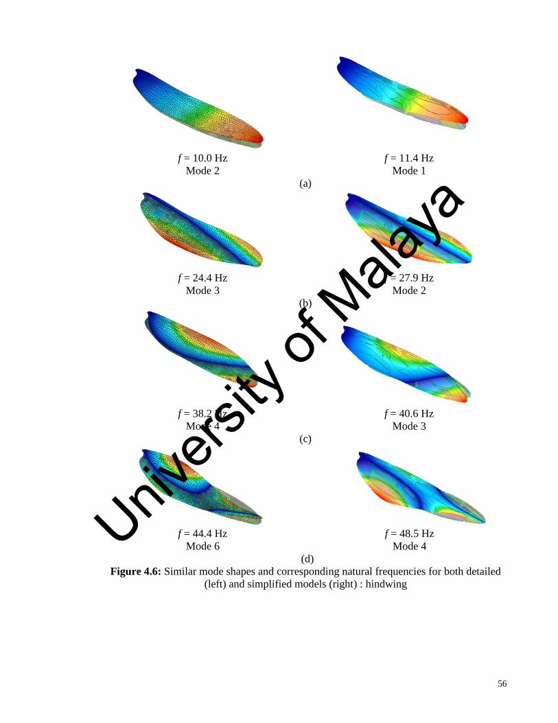
56
f = 10.0 Hz f = 11.4 Hz
Mode 2 Mode 1
(a)
f = 24.4 Hz f = 27.9 Hz
Mode 3 Mode 2
(b)
f = 38.2 Hz f = 40.6 Hz
Mode 4 Mode 3
(c)
f = 44.4 Hz f = 48.5 Hz
Mode 6 Mode 4
(d)
Figure 4.6: Similar mode shapes and corresponding natural frequencies for both detailed
(left) and simplified models (right) : hindwing
Univers
ity of
Mala
ya
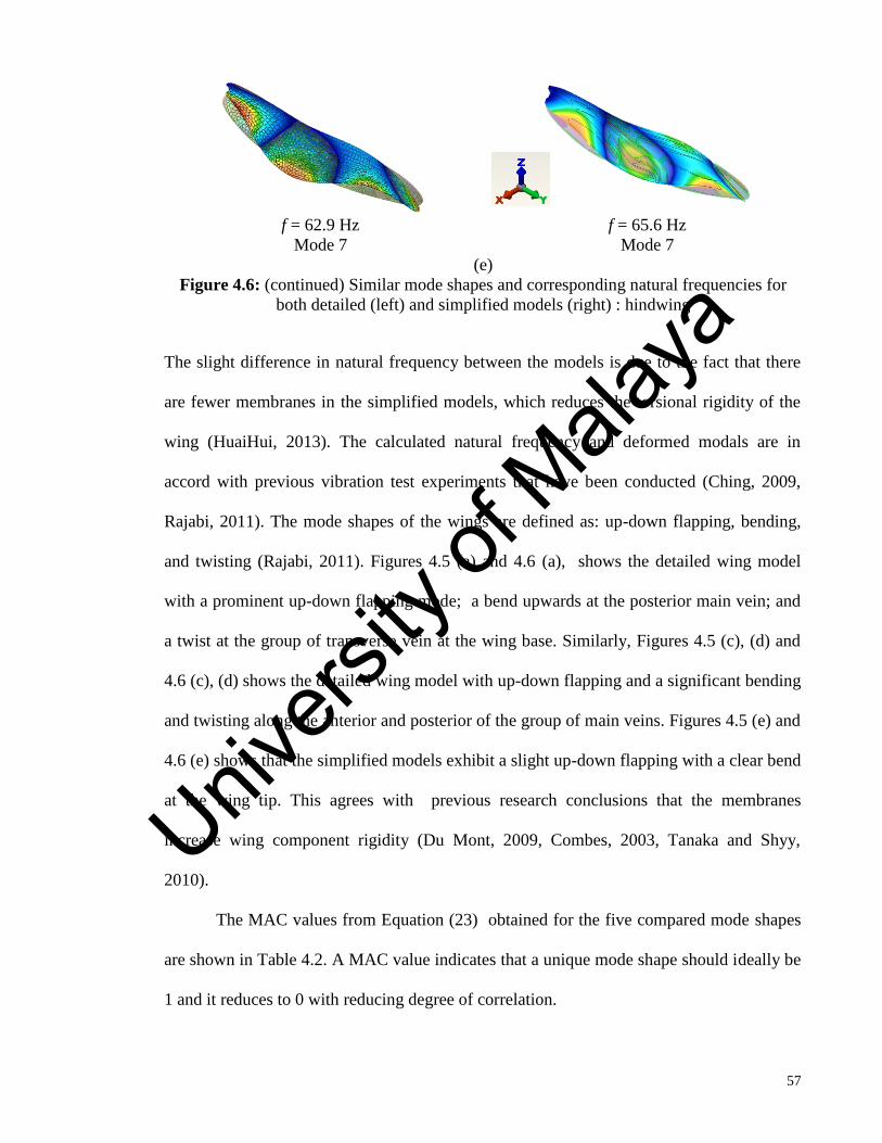
57
The slight difference in natural frequency between the models is due to the fact that there
are fewer membranes in the simplified models, which reduces the torsional rigidity of the
wing (HuaiHui, 2013). The calculated natural frequency and deformed modals are in
accord with previous vibration test experiments that have been conducted (Ching, 2009,
Rajabi, 2011). The mode shapes of the wings are defined as: up-down flapping, bending,
and twisting (Rajabi, 2011). Figures 4.5 (a) and 4.6 (a), shows the detailed wing model
with a prominent up-down flapping mode; a bend upwards at the posterior main vein; and
a twist at the group of transverse vein at the wing base. Similarly, Figures 4.5 (c), (d) and
4.6 (c), (d) shows the detailed wing model with up-down flapping and a significant bending
and twisting along the anterior and posterior of the group of main veins. Figures 4.5 (e) and
4.6 (e) shows that the simplified models exhibit a slight up-down flapping with a clear bend
at the wing tip. This agrees with previous research conclusions that the membranes
increase wing component rigidity (Du Mont, 2009, Combes, 2003, Tanaka and Shyy,
2010).
The MAC values from Equation (23) obtained for the five compared mode shapes
are shown in Table 4.2. A MAC value indicates that a unique mode shape should ideally be
1 and it reduces to 0 with reducing degree of correlation.
f = 62.9 Hz f = 65.6 Hz
Mode 7 Mode 7
(e)
Figure 4.6: (continued) Similar mode shapes and corresponding natural frequencies for
both detailed (left) and simplified models (right) : hindwing
Univers
ity of
Mala
ya
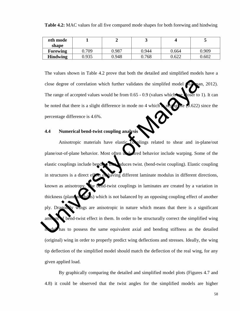
58
Table 4.2: MAC values for all five compared mode shapes for both forewing and hindwing
nth mode
shape
1 2 3 4 5
Forewing 0.709 0.987 0.944 0.664 0.909
Hindwing 0.935 0.948 0.768 0.622 0.602
The values shown in Table 4.2 prove that both the detailed and simplified models have a
close degree of correlation which further validates the simplifed model (Rahman, 2012).
The range of accepted values would be from 0.65 - 0.9 (values which are closer to 1). It can
be noted that there is a slight difference in mode no 4 which is negligible (0.622) since the
percentage difference is 4.6%.
4.4 Numerical bend-twist coupling analysis
Anisotropic materials have elastic couplings related to shear and in‐plane/out
plane/out‐of‐plane behavior. Most often undesired behavior include warping. Some of the
elastic couplings include bending that induces twist. (bend-twist coupling). Elastic coupling
in structures is a direct effect of having different laminate modulus in different directions,
known as anisotropy. The bend-twist couplings in laminates are created by a variation in
thickness (plane modulus) which is not balanced by an opposing coupling effect of another
ply. Dragonfly wings are anisotropic in nature which means that there is a significant
amount of bend-twist effect in them. In order to be structurally correct the simplified wing
model has to possess the same equivalent axial and bending stiffness as the detailed
(original) wing in order to properly predict wing deflections and stresses. Ideally, the wing
tip deflection of the simplified model should match the deflection of the real wing, for any
given applied load.
By graphically comparing the detailed and simplified model plots (Figures 4.7 and
4.8) it could be observed that the twist angles for the simplified models are higher
Univers
ity of
Mala
ya

59
(approximately 3-5%) than those of the detailed model. Moreover, the trend of deflection
(bending) is the same in all plots confirming the observation. The basal leading edge of
dragonfly wings are highly corrugated structures, which improves its flexural and bending
stiffness (Combes, 2003 and Tanaka, 2010). This prevents chord-wise flattening especially
at the main veins. None of our models includes this complexity. The lack of corrugated
edges will generally not be an issue for a BMAV wing if rigid, metallic structures are used,
rather than the chitin-based structures in actual dragonfly wings. Studies have shown that
the corrugation has only a slight effect on the wing’s aerodynamics, because the scale of
corrugation is small compared to the separated flow region and size of the leading edge
vortex (Xue Li, 2009). Therefore, corrugated wings will provide structural benefits without
significant effect on aerodynamic lift production.
Univers
ity of
Mala
ya

60
Figure 4.7: The static bend-twist coupling graph of both detailed and simplified models;
forewing
Univers
ity of
Mala
ya
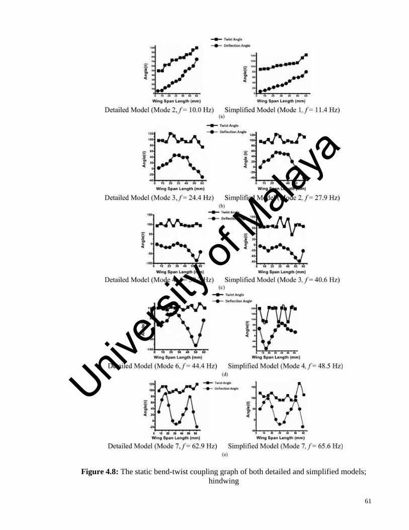
61
Figure 4.8: The static bend-twist coupling graph of both detailed and simplified models;
hindwing
Univers
ity of
Mala
ya
62
4.5 Tensile test simulation results
Simulation results were obtained before the experiments were conducted. Both
tensile and bending experiment results were analyzed and the stress distribution was
observed. Simulation tensile test results were observed and critical or high stress areas
were marked as points of fractures. These results helped in identifying the weak areas
(regions) of the wing models of different materials and the maximum stress that the models
could withstand.
4.5.1 Tensile test simulation results (wing frames without membrane)
The first experimental tests involved the wing frame structures without their
membranes. (The material specifications for these models are stated in Table 3.2.) Figure
4.9 shows the von Mises stress results of all the seven different frame structures. The ‘max’
(maximum) and ‘min’ (minimum) pointers indicate the area where the stress is the highest.
The highest stress in the forewing recorded for stainless steel (Type 321), balsa wood,
black graphite carbon fiber,red prepreg fiberglass, PLA, acrylic and ABS is: 2.54N/mm2,
0.04N/mm2, 2.03 N/mm
2, 0.03 N/mm
2, 13 N/mm
2, 17 N/mm
2, 23 N/mm
2 respectively. A
close observation from the results shows that the high stress point for all seven materials,
except for balsa wood and acrylic, occurs in the same region. This region is located where
the surface-to-area ratio is at its minimum value. The maximum stress on the balsa wood
wing occurred at the grip point. Based on previous studies (Da Silva, 2007), balsa wood,
and acrylic to a certain extent, under compression in the axial direction exhibits a linearly
elastic regime that terminates by the initiation of failure in the form of localized kinking.
Geometric imperfections in the form of fiber waviness, and failure was found to
lead to kink bands with distinct orientations and widths (Kyriakides, 1995). Subsequently,
Univers
ity of
Mala
ya

63
under displacement-controlled compression, a stress plateau is traced that is associated with
the gradual spreading of crushing of the cells through the material. The material is less stiff
(i.e. weaker) in the tangential and radial directions. Compression in these directions crushes
the tracheids (phloem of the wood) laterally. Figure 4.10 shows the results for the
hindwing. The maximum stress occurs in approximately the same location for all the wing
frame structures. This region corresponds with the minimum surface-to-area ratio. The
minimum stress also occurs in a similar location for all of the wing frames, except for the
balsa wood and acrylic frame. The readings are 2.31 N/mm2, 0.08 N/mm
2, 1.39 N/mm
2,
0.02 N/mm2, 12 N/mm
2, 17 N/mm
2 and 24 N/mm
2 for stainless steel (Type 321), balsa
wood, black graphite carbon fiber and red prepreg fiberglass, PLA, acrylic and ABS
respectively. The minimum stress for the balsa wood and acrylic frame occurs in the
cambered edge, because it experiences the lowest compression stress. This has been
observed for balsa wood in past studies (Borrega, 2015, Osei, 2013 and 2014)
(a) (b)
(c) (d)
Figure 4.9: Von Mises stress simulation results of different forewing frame structures; (a)
stainless steel (Type 321), (b) balsa wood, (c) black graphite carbon fiber, (d) red prepreg
fiberglass e) PLA, f) acrylic, g) ABS
Univers
ity of
Mala
ya

64
(e) (f)
(g)
Figure 4.9 (continued): Von Mises stress simulation results of different forewing frame
structures; (a) stainless steel (Type 321), (b) balsa wood, (c) black graphite carbon fiber, (d)
red prepreg fiberglass e) PLA, f) acrylic, g) ABS
(a) (b)
(c) (d)
Figure 4.10: Von Mises stress simulation results of different forewing frame structures; (a)
stainless steel (Type 321), (b) balsa wood, (c) black graphite carbon fiber, (d) red prepreg
fiberglass, e) PLA, f) acrylic, g) ABS
Univers
ity of
Mala
ya

65
(e) (f)
(g)
Figure 4.10 (continued): Von Mises stress simulation results of different forewing frame
structures; (a) stainless steel (Type 321), (b) balsa wood, (c) black graphite carbon fiber, (d)
red prepreg fiberglass, e) PLA, f) acrylic, g) ABS
Univers
ity of
Mala
ya

66
4.5.2 Tensile test simulation results (wing frames with membrane)
Simulation results were also obtained for the wing frames with their membranes.
Figure 4.11 shows the forewing models of all four materials. Based on Figure 4.11, the
maximum von Mises stress occurs at approximately the same location for all seven
materials. This location is different from the models without membranes (Figure 4.9).
However, the highest stresses occur again in regions where the surface-to-area ratio is
minimum. An exception is seen in the wing frame made of black graphite carbon fiber
laminate, where the maximum stress occurs in the cambered edge of the wing. This is due
to the fact that carbon fiber undergoes delamination at areas where the kinks and curves are
located. (Tamilarasan, 2015). The region where maximum stress occurs shows a potential
area of delamination. The maximum stress recorded is: 2.05 N/mm2, 0.097 N/mm
2, 49.3
N/mm2,
2.10 N/mm2, 14.77 N/mm
2, 17.29 N/mm
2, and 24.23 N/mm
2 for stainless steel
(Type 321), balsa wood, black graphite carbon fiber, red prepreg fiberglass, PLA, acrylic
and ABS, respectively.
Univers
ity of
Mala
ya

67
Figure 4.11: von Mises stress simulation results of different forewing model structures; (a)
stainless steel (type 321), (b) balsa wood, (c) black graphite carbon fiber, (d) red prepreg
fiberglass, (e) PLA, (f) acrylic, (g) ABS
Univers
ity of
Mala
ya

68
The stress distribution of the hindwings with their membranes (shown in Figure
4.12) is also different than the wings without their membranes (shown in Figure 4.10). The
maximum stresses for all of these wing models occurs on the membrane and not the frame.
This is due to compression of the membrane in that region. This indicates that there is a
high probability that the membrane in this region will be damaged. The maximum stress
recorded is: 3.28 N/mm2, 1.04 N/mm
2, 41.05 N/mm
2, 3.09 N/mm
2, 13.87 N/mm
2, 16.96
N/mm2, 23.46 N/mm
2 for stainless steel (Type 321), balsa wood, black graphite carbon.
(a) (b)
(c) (d)
(e) (f)
Figure 4.12: von Mises stress simulation results of different hindwing model structures; (a)
stainless steel (Type 321),(b) balsa wood, (c) black graphite carbon fiber, (d) red prepreg
fiberglass, (e) PLA, (f) acrylic, (g) ABS
Univers
ity of
Mala
ya

69
(g)
Figure 4.12: (continued) von Mises stress simulation results of different hindwing model
structures; (a) stainless steel (Type 321),(b) balsa wood, (c) black graphite carbon fiber, (d) red
prepreg fiberglass, (e) PLA, (f) acrylic, (g) ABS
4.5.3 Bending test simulation results (wing frames without membrane)
Some of the wing frames without membrane were subjected to bending tests. Only
the steel and balsa wood frame structures were subjected to this bending test. Attempts to
conduct bending tests on the red prepreg fiberglass, black graphite carbon fiber laminates,
PLA, acrylic and ABS wing frame structures gave trivial results. These materials do not fail
when subjected to bending test experiments (Babukiran et al, 2014). Therefore, the
simulation results for black graphite carbon fiber, red prepreg fiberglass laminates, PLA,
acrylic and ABS were not included.
Figures 4.13 and 4.14, shows the von Mises stress simulation results for the
forewing and hindwing structures. The bending simulation results show uniformity in the
stress distribution of all four frame structures for both forewing and hindwing. The
maximum stress occurred in the same relative region for all four different frame structures,
regardless of the wing type. This shows that bending creates a localized stress in both of the
materials used. Combes et al. 2003 found that the flexural stiffness across the wing base
line is maximum when it is subjected to bending (Combes, 2003). The hinge of a dragonfly
Univers
ity of
Mala
ya

70
wing must be able to withstand different types of loads, including forces subjected to
rotational and translational motion. Hence the maximum stress occurred at the region near
the wing base (where the pivot point is located), as highlighted in the simulation results.
The maximum bending stresses for the forewings of stainless steel and balsa wood are:
0.80 N/mm2 and 0.11 N/mm
2, respectively. The hindwing maximum stress was: 0.64
N/mm2 and 0.05 N/mm
2 for stainless steel and balsa wood, respectively.
(a) (b)
Figure 4.13: von Mises stress simulation results of different forewing model structures; (a)
stainless steel (Type 321), and (b) balsa wood
(a) (b)
Figure 4.14: von Mises stress simulation results of different hindwing model structures; (a)
stainless steel (Type 321), and (b) balsa wood
Univers
ity of
Mala
ya

71
4.5.4 Bending test simulation results (wing frames with membrane)
(a) (b)
Figure 4.15: von Mises stress simulation results of different forewing model structures; (a)
stainless steel (Type 321), and (b) balsa wood
(a) (b)
Figure 4.16. Von Mises stress simulation results of different hindwing model structures;
(a) stainless steel (Type 321), and (b) balsa wood
Figures 4.15 and 4.16 shows the bending stress created on the wing frames with
their membrane. The results show that the tips of the wings undergo damage faster than the
base of the wing. The figures also indicate that there is a greater probability of the
membrane undergoing damage than the frame structure. The region where the tip of the
wing undergoes bending deformation matches previous studies that have been conducted
(HuaiHui, 2012 and 2013, Wakelling, 1997, Jiyu Sun, 2012 and Jongerius, 2010). The von
Mises stress for the hindwing is 2.09 and 0.09 N/mm2
for stainless steel and balsa wood,
Univers
ity of
Mala
ya
72
respectively. However, only the results obtained here clearly show the effects of the
bending load on the membrane of an artificial dragonfly wing.
4.5.5 Tensile test experimental results
Figures 4.17 and 4.18 compare the forewing and hindwing for all seven different
frame structure materials. They also compare the results of models with and without
membranes, allowing the effects of the chitosan film on the frame structures to be
observed. All four materials (without membrane) exhibit their original properties under
tensile stress, which agrees with previous studies (David, 2014, Borrega, 2015, da Silva,
2007, Osei 2013 and 2014, Wang, 2013, Warren, 2015, and Tamilarasan, 2015). Both
figures show a sudden decline in tensile stress, which indicates failure (fracture) has
occurred (destructive testing). Figure 4.17(a) compares the steel forewing with and without
membrane. The ultimate strength of the steel forewing with its membrane is 2.10 MPa and
without membrane is 2.48 MPa. These values are 2.20 MPa with membrane and 2.45 MPa
without membrane for the hindwing. These results show that the addition of the film
membrane causes an 8% reduction of strength for the steel wing. The chitin nano-
composite membrane solution oxidizes the stainless steel wing frame. We observed
aggressive oxidation in our samples, even though precautions were taken to avoid it.
Therefore, it can be concluded that adhesion of the film membrane to the stainless steel
reduces its overall stress resistance and increases its oxidation. Therefore, stainless steel is
a poor choice of material for the wing frame, when desiring to use a chitin nano-composite
film wing membrane. Referring to Figures 4.11(a) and 4.12(a), the percent difference
between the simulation and experiments are approximately 4.0% and 3.52%, with and
without membranes, respectively. The simulation results do not take into count the decrease
Univers
ity of
Mala
ya
73
of strength caused by chemical degradation. The percentage results shows a good
agreement between the experiment conducted and the simulation analysis obtained.
Figures 4.17(b) and 4.18(b) shows a comparison of balsa wood with and without
membrane for both fore and hindwings. In contrast to stainless steel, the membrane reduces
the stress acting on the balsa wood wing frame. The ultimate strength of the balsa wood
forewing, with and without membrane, is 0.09 MPa and 0.03 MPa, respectively. The results
of the hindwing, with and without membrane, were: 0.09 MPa and 0.04 MPa, respectively.
This equates to an increase in ultimate strength that ranges from 125% to 200%. Therefore
it can be concluded that adhesion of the chitosan nano-composite film to the balsa wood
increases its strength tremendously. Referring to Figures 4.11(b) and 4.12(b), the percent
difference between the simulation and experiments are approximately 6.23% and 4.56%,
with and without membranes, respectively.
Figures 4.17(c) and 4.18(c) shows a comparison of carbon fiber wings, with and
without film membranes. The adhesion of chitosan nano-composite film yields an immense
increase in strength. The peak tensile strength for the forewings, with and without
membranes, are 48.07 MPa and 1.32 MPa, respectively. The results for the hindwings, with
and without membranes, are 40.06 MPa and 1.34 MPa, respectively. This shows that the
addition of film increases the ultimate strength by 3000% to 3600%. This shows that the
adhesion of the film to these carbon fiber models greatly intensifies its ultimate strength.
Referring to Figures 4.11(c) and 4.12(c), the percentage differences between the simulation
and experiments are approximately 5.23% and 3.87%, with and without membranes,
respectively.
Figures 4.17(d) and 4.18(d) shows the results obtained for red prepreg fiberglass
model wings. These results also show an increase in ultimate strength after adhesion of the
chitosan nano-composite film. The ultimate strength for the forewing, with and without
Univers
ity of
Mala
ya

74
membranes, are: 2.03 MPa and 0.01 MPa, respectively. The ultimate strength for the
hindwings, with and without membranes, is 3.04 MPa and 0.01 MPa, respectively.
However, the red fiberglass undergoes warping and shrinkage at a very early stage of the
experiment (1 minute after starting the experiment). So this phenomenon must be taken
under consideration when considering this material for fabrication purpose. Referring to
Figures 4.11(d) and 4.12(d), the percent differences between the simulation and
experiments are approximately 5.75% and 8.93%, with and without membranes,
respectively.
Figures 4.17(e) and 4.18(e) shows a comparison of PLA wings, with and without
film membranes. The adhesion of chitosan nano-composite film yields an increase in
strength. The peak tensile strength for the forewings, with and without membranes, is
200.07 MPa and 175.46 MPa, respectively. The results for the hindwings, with and without
membranes, are 197.33 MPa and 162.06 MPa, respectively. This shows that the addition of
film increases the ultimate strength by 14% to 22%. This shows that the adhesion of the
film to these PLA models moderately increases its ultimate strength. Referring to Figures
4.11(e) and 4.12(e), the percentage differences between the simulation and experiments are
approximately 2.62% and 3.81%, with and without membranes, respectively.
Figures 4.17(f) and 4.18(f) shows a comparison of acrylic wings, with and without
film membranes. The adhesion of chitosan nano-composite film yields noticeable amount
of increase in strength. The peak tensile strength for the forewings, with and without
membranes, is 173.27 MPa and 168.95 MPa, respectively. The results for the hindwings,
with and without membranes, are 188.71 MPa and 179.16 MPa, respectively. This shows
that the addition of film increases the ultimate strength by 2% to 5%. This shows that the
adhesion of the film to these acrylic models slightly increases its ultimate strength.
Referring to Figures 4.11(f) and 4.12(f), the percentage differences between the simulation
Univers
ity of
Mala
ya

75
and experiments are approximately 2.12% and 3.55%, with and without membranes,
respectively.
Figures 4.17(g) and 4.18(g) shows a comparison of ABS wings, with and without
film membranes. The adhesion of chitosan nano-composite film yields noticeable amount
of increase in strength. The peak tensile strength for the forewings, with and without
membranes, is 265.77 MPa and 275.23 MPa, respectively. The results for the hindwings,
with and without membranes, are 244.88 MPa and 257.61 MPa, respectively. This shows
that the addition of film increases the ultimate strength by approximately 5%. This shows
that the adhesion of the film to these acrylic models slightly increases its ultimate strength.
Referring to Figures 4.11(g) and 4.12(g), the percentage differences between the simulation
and experiments are approximately 1.73% and 1.56%, with and without membranes,
respectively.
Univers
ity of
Mala
ya

76
(a)
(b)
(c)
Figure 4.17: Tensile stress vs tensile strain (engineering) of all four forewing frame
structures ; a) stainless steel (Type 321), b) balsa wood, c) black graphite carbon fiber, d)
red prepreg fiberglass, e) PLA, f) acrylic and g) ABS
Univers
ity of
Mala
ya

77
(d)
(e)
(f)
Figure 4.17: (continued) Tensile stress vs tensile strain (engineering) of all four forewing
frame structures ; a) stainless steel (Type 321), b) balsa wood, c) black graphite carbon
fiber, d) red prepreg fiberglass, e) PLA, f) acrylic and g) ABS Univ
ersity
of M
alaya
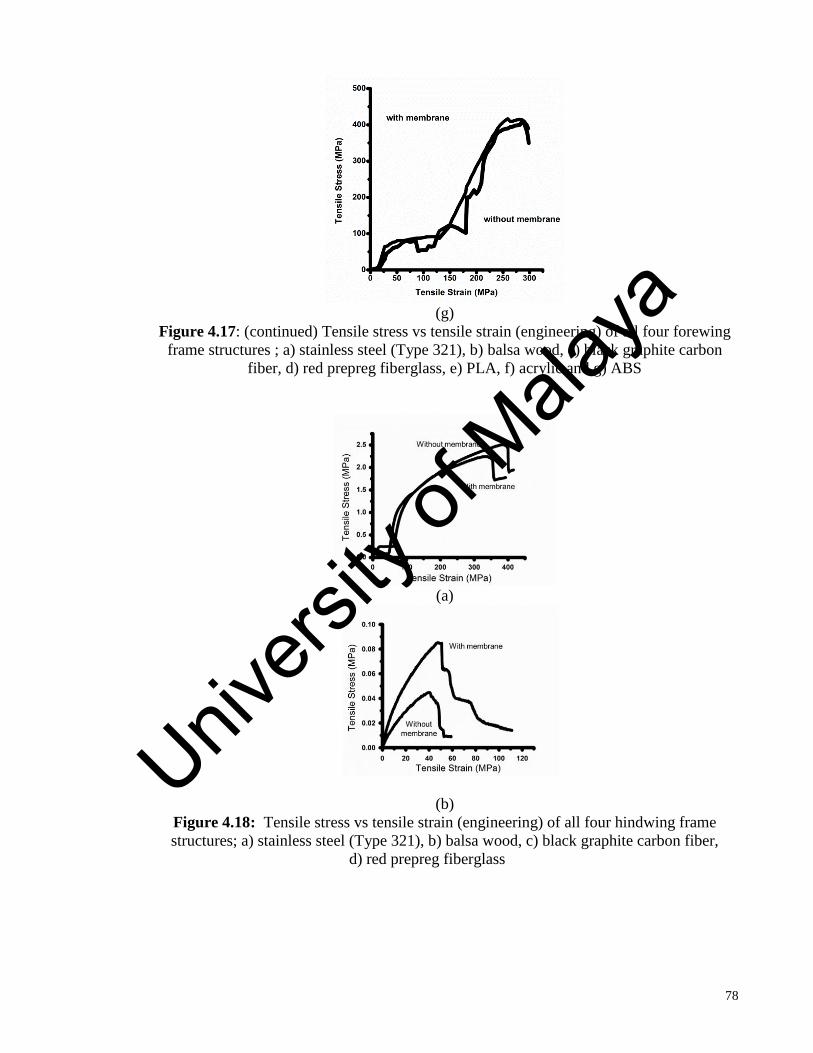
78
(g)
Figure 4.17: (continued) Tensile stress vs tensile strain (engineering) of all four forewing
frame structures ; a) stainless steel (Type 321), b) balsa wood, c) black graphite carbon
fiber, d) red prepreg fiberglass, e) PLA, f) acrylic and g) ABS
(a)
(b)
Figure 4.18: Tensile stress vs tensile strain (engineering) of all four hindwing frame
structures; a) stainless steel (Type 321), b) balsa wood, c) black graphite carbon fiber,
d) red prepreg fiberglass
Univers
ity of
Mala
ya

79
(c)
(d)
(e)
Figure 4.18: (continued) Tensile stress vs tensile strain (engineering) of all four hindwing
frame structures; a) stainless steel (Type 321), b) balsa wood, c) black graphite carbon
fiber, d) red prepreg fiberglass
Univers
ity of
Mala
ya

80
(f)
(g)
Figure 4.18: (continued) Tensile stress vs tensile strain (engineering) of all four
hindwing frame structures; a) stainless steel (Type 321), b) balsa wood, c) black graphite
carbon fiber, d) red prepreg fiberglass
4.5.6 Bending test experimental results
Figures 4.19 and 4.20 show the compression stress vs strain of the wing models
made of stainless steel and balsa wood, respectively. Figures 4.17 and 4.18 showed a
reduction in the ability of the wing frame to undergo tension when the film membrane is
adhered to the stainless steel. However, this testing shows that its resistance to compression
is higher in the wing models with film. Figures 4.19(a) and 4.20(a) show results for the
stainless steel frames, both the fore and hindwings. The peak strength is 2.02 MPa with
membrane and 0.75 MPa without membrane. This is an increase of 167%. The hindwings
are 2.03 MPa and 0.63 MPa, with and without membrane, respectively. This is an increase
Univers
ity of
Mala
ya

81
of 140%. Referring to Figure 4.15 and 4.16, the percent difference between the simulation
and experiments are approximately 9.97% and 8.74%, with and without membranes,
respectively.
Figures 4.19(b) and 4.20(b) show results for the balsa wood frame structures. The
peak strength for the forewing structure, with and without membrane, is 0.08 MPa and 0.04
MPa, respectively. The hindwings are 0.08 MPa and 0.04 MPa, with and without
membrane, respectively. This is an increase of approximately 200% for both balsa wood
fore and hindwings. Referring to Figure 4.16, the percent difference between the simulation
and experiments are approximately 6.49% and 7.77%, with and without membranes,
respectively.
(a) (b)
Figure 4.19: Compression stress versus compression strain graphs of forewing
wing models. (a) stainless steel (Type 321), (b) balsa wood
Univers
ity of
Mala
ya

82
4.6 High speed camera image results analysis
The high speed camera imaging experiment was conducted on each of the three
types of wings; PLA, acrylic and ABS (both with and without the chitosan membranes).
This was done to study the flexibility of each wing frame material and to determine the best
material for use in a BMAV. An actual dragonfly wing (Diplacodes Bipunctata) was also
tested to study its motion during passive flapping at different frequencies and compare it
with the fabricated wings. The nomenclature for wing rotation about different axis is shown
in Figure 4.21. This figure shows the types of rotation that an insect wing undergoes.
Figures 4.22 and 4.23 shows a sequence of images, illustrating the wing motion of an actual
flapping dragonfly wing during one complete flapping cycle. The wing beat frequency for
these images is 30 Hz, which is the nominal wing beat frequency of this species of
dragonfly. These figures show the common mode of flapping of an actual insect wing
(dragonfly). At all frequencies from 10-250 Hz, the flapping motion is similar. As for the
fabricated wings (all seven materials), the models only exhibit an up-down flapping
motion. They lack the twist and bend motion exhibited in an actual insect wing.. The
Figure 4.20: Compression stress vs compression strain for hindwing models. (a)
Stainless steel (Type 321), (b) Balsa wood
Univers
ity of
Mala
ya

83
twisting motion of an actual dragonfly wing can be seen clearly in Figures 4.22 (b), (c), (d),
(e) and 4.23(b), (c), (d), and (e). This twisting motion cannot be achieved by our fabricated
wing models. This will affect the aerodynamics performance of the wing. However, the
wing exhibits shown by these (PLA, acrylic and ABS) wings. Based on our previous
simulation and experimental analysis mentioned in Section 4.5 and 4.6, it has been
concluded that out of the seven materials, the three best materials were PLA, acrylic and
ABS. These materials were chosen for following reasons:
The thickness of the material was much thinner compared to steel, balsa,
carbon fiber and red prepreg ( less than 2mm). This matches the criteria of a
dragonfly wing whereby the wings are supposed to be thin.
These materials were much more flexible than the first four materials
mentioned above (steel, balsa, carbon fiber and red prepreg)
The simulation and experimental results shows a better agreement of when
compared to an actual dragonfly wing. The percentage difference of strength
between the actual dragonfly wing ( based on previous literature) and the
three materials (PLA, acrylic and ABS) ranged about 2%-5% which further
strengthens the rationale of selecting these materials
Furthermore, in the flapping mechanism experiment, only the forewings were chosen to be
tested. The difference between the forewing and hindwings tested previously (as mentioned
in Section 4.5 and 4.6) yields strength results that were similar (with a percentage
difference of 1%-2%) for both forewing and hindwing (with and without membrane).
Also, according to previous literature, the hindwings act as a wing that generates lift during
the flapping motion (Zheng Hu, 2009) Our experiments were based on a non-vacuum
Univers
ity of
Mala
ya

84
environment, (open air), hence the larger surface area of the hindwing shall affect the
measurement parameters greatly. (bend angle, displaced distance and twist angle)
Figure 4.21: Degrees of freedom for the wings of flying insects
Univers
ity of
Mala
ya

85
a)
b)
c)
d)
e)
f)
Figure 4.22: Side view of the actual dragonfly flapping wing (gray scale) captured by the
high speed camera during one flapping cycle at 30Hz. a) start of downstroke, b) mid-
downstroke, c) end of downstroke, d) start of upstroke, e) mid-upstroke, f) end of upstroke
Univers
ity of
Mala
ya
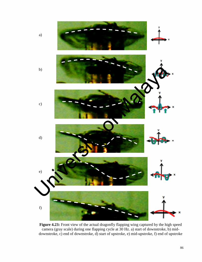
86
a)
b)
c)
d)
e)
f)
Figure 4.23: Front view of the actual dragonfly flapping wing captured by the high speed
camera (gray scale) during one flapping cycle at 30 Hz. a) start of downstroke, b) mid-
downstroke, c) end of downstroke, d) start of upstroke, e) mid-upstroke, f) end of upstroke
Univers
ity of
Mala
ya

87
Dragonfly wings greatly deform during flight. This was observed in our experiment
as well as others (Hisayoshi, 2014). Despite having a certain degree of rigidity, dragonfly
wings undergo a considerable amount of bending, twisting and rotational motions. Figure
4.22 and 4.23 shows the motion of flapping wing in one complete cycle at 30 Hz (side and
front view). It was observed that at both directions (chord and spanwise) an asymmetric
twist-bend motion was observed. Figures 4.22(d), 4.22 (f), and 4.23(d) clearly show these
asymmetric motions mentioned. At the end of an upstroke (observed in Figure 4.22(e), the
wing momentarily exhibited a symmetrical twisting motion. A large feathering rotation
range of 154° to 179° of the entire wing was observed during the beginning of the down
stroke and end of the upstroke (for all frequencies) (Figure 4.23(a) and 4.23(e). Even
during the steady phase (passive moment occurring when the flapping angle is zero), the
wing is observed to undergo internal torsion. This corresponds well to previous studies
made by Wootton et al. (Wooton, 1981 and 1993)
Besides the nominal 30 Hz wing beat frequency, the dragonfly wing was also
flapped at frequencies of: 10, 20, 70, 120, 200, and 250 Hz. The pattern of deformations
was similar for all of the frequencies observed. The measured bending angle, wing tip
deflection, wing tip twist angle and speed for the different wing frames (without and with a
membrane) were plotted for comparison to the results obtained from an actual dragonfly
wing in Figures 4.24-4.27.
4.6.1 Bending angle versus flapping frequency
The bending angle is directly proportional to the flexibility of the wing. Previous
studies have shown that wing flexibility has a significant influence on the aerodynamic
forces (e.g. lift and thrust) generated by the flapping wing ( Zhao, 2009). However, this
study focuses only on the chordwise flexibility of a passive flapping wing. Bending angles
Univers
ity of
Mala
ya
88
were measured along the chordwise direction. Chang et al.(2013) also investigated
chordwise flexibility, but for simple, non-anisotropic wing structures. They presented a
detailed assessment of the effects of structural flexibility on the aerodynamic performance
of flapping wings. The Reynolds number (Re =100) considered in this study is relevant to
small insect flyers, such as fruit flies. However, this study only includes the role of
chordwise flexibility and passive pitch in two dimensional plunging motions.
Our study involves a much more complex wing design than this past study by
Chang, 2013.. Figure 4.24 shows the bending angles as the wing beat frequency is varied
for the three fabricated wing frames (without and with a membrane) in comparison to an
actual dragonfly wing. These figures show that the maximum bending angle (θmax) for all
the wings occurs during the upstroke. This was observed for both frames (without and with
a membrane). This agrees with previous research done by Jongerius et al. (2010) in which
this asymmetry (difference in bending angle between the upstroke and down stroke) was
attributed to the directional bending stiffness in the wing structure (e.g. one-way hinge or a
pre-existing camber in the wing surface)
The maximum bending angle of dragonfly wings at 30 Hz is recorded to be about
6°. The wings were observed to have a maximum bending angle of 10.7° at 120 Hz (natural
frequency of an actual dragonfly). This is an increase of 78.3% from 30 Hz. ABS shows a
high level of flexibility compared to the other two materials used. Figure 4.24 shows that
the bending angle curves of the fabricated ABS wings are more similar to the actual
dragonfly wing than the other two types. Figure 4.24(a) shows that the bending angle of
ABS wing (without membrane) at 30 Hz is 8.5° and 5.9° at 120 Hz. At 30 Hz, the
percentage difference between an ABS wing (without membrane) and an actual dragonfly
wing is about 41.7%. The PLA and acrylic wings each recording a percentage difference
(reduction) of 70%. In Figure 4.24(b), ABS exhibits much larger bending angles at 30 Hz
Univers
ity of
Mala
ya

89
when the membrane is added. The value of the ABS wing (with membrane) is 20.1° at 30
Hz and 34.9° at 120 Hz. This angle is much larger than the actual dragonfly wing. The
percentage increase between the ABS and an actual dragonfly wing is 233.3%. The other
two materials (PLA and acrylic) exhibited much lower bending angles than the actual
dragonfly wing. The percentage reduction in PLA and acrylic (in comparison to an actual
dragonfly wing) is 83.3% and 75%, respectively.
These observations confirm that the overall flexibility of the wing decreases after
the membrane is attached, except for ABS. At a frequency of 120 to 170 Hz, the dragonfly
wing bends at a very high angle. Previous research shows that dragonflies do not flap at
their natural frequency (120 to 170 Hz) (Maria, 2011). So this result is likely due to a
resonance effect caused by the wing beat frequency being proximate to the natural
frequency of the wing. This result confirms that dragonflies have a maximum wing beat
frequency limitation in this range. The ABS wing frame shows a similar trend at 120 Hz.
The bending angle is reduced at frequencies greater than 120 Hz for both the actual
dragonfly wing and the three fabricated wings.
(a) (b)
Figure 4.24: Bending angle of different wing frames; (a) without membrane and (b) with
membrane.
Univers
ity of
Mala
ya

90
4.6.2 Wing tip deflection versus flapping frequency
Figures 4.25(a) and (b) show the wing tip deflection for varying wing beat
frequencies of the three fabricated wing frames (without and with membranes) in
comparison to an actual dragonfly wing. Similar to bending angle, deflection is another
measurement that can be used to assess a flapping wing’s flexibility. As mentioned earlier,
past studies have shown that wing flexibility has a significant effect on the wing’s ability to
generate a suitable time-averaged lift or thrust (Zhao, 2009). Similar to θmax in Figure 4.24,
Figure 4.25 shows that the maximum deflection (dmax) occurs during the upstroke. This
again was observed for both frames (without and with a membrane). This agrees with
previous research done by Luo et al (2012).
Figure 4.25 (a) shows that all of the fabricated wing frames (without membrane)
deflect at magnitudes that are similar (only slightly reduced) to the actual dragonfly wing at
30 Hz which is about 7.1 mm. At 30 Hz, ABS has a percentage increase of 23.94%. PLA
and acrylic both have a percentage reduction of 47.71% and 62% respectively. However
Figure 4.25 (b) shows that the fabricated wing frames (with membranes) have very
different deflections than the actual dragonfly wing. Only the ABS wing showed a
comparable level of deflection, however the dragonfly wing is 40.85% lower than the ABS
wing. The PLA and acrylic wings have percentage reduction of 94.37% and 66.2%,
respectively compared to the dragonfly wing. The actual dragonfly wing is able to undergo
a large deflection at the tip region. This supports previous studies which explain that the
difference between the deflection at the tip and the surface is created by differences of the
rigidity (due to the vein and corrugations) along the wing surfaces (Charles, 2011).
The difference in deflection between wing frames without a membrane and with a
membrane shows that the attachment of a membrane causes an increase in rigidity. This
increase in rigidity is observed to be the highest in the PLA wing. Only the ABS wing
Univers
ity of
Mala
ya

91
shows a similar curvature trend with the actual dragonfly wing around 120 Hz. At 120 Hz,
an increase in percentage of 81.7% (without membrane) and decrease in percentage of
69.7% (with membrane) is seen in ABS wing frame. Compared to the PLA wing there is a
percentage reduction of 82.6% (without membrane) and 64.2% (with membrane). The
acrylic wing has a percentage reduction of 85.3%, both without and with the membrane
attached. The trend of the graph again shows that there is a decrease in flexibility after the
membrane has been attached. Two high peaks were observed for an actual dragonfly wing
(30 and 120 Hz). As already stated, the natural frequency of dragonfly wings has been
reported to be between 120 to 170 Hz (Maria, 2011). The extreme fluctuation observed in
this range confirms the observation.
(a) (b)
Figure 4.25: Wing tip deflection of different wing frames; (a) without membrane and (b)
with membrane
4.6.3 Wing twist angle versus flapping frequency
Figure 4.26 shows the maximum wing tip twist angle of the three fabricated wing
frames in comparison to an actual dragonfly wing. The maximum twist angle was recorded
during the stroke reversal (transition from upstroke to down stroke). The twist angle for an
actual dragonfly wing at 30 Hz is 154.58°. Untwisted wings have large; drag producing
Univers
ity of
Mala
ya
92
wing surfaces that are exposed to flow hence, the importance of twisting in wings is
justified. Wing tip twist also plays an important role in enhancement of flight performance.
The mid-stroke timing of wing deformation in the butterfly, examined by Lingxiao et al
(2013), suggests that the deformation is not due to wing inertia, because the acceleration of
the wing is small at this point in the stroke. They suggest that this is instead due to
aeroelastic effects, since the aerodynamic forces are very large at mid-stroke.
Figures 4.26 (a) and (b) show that both the PLA and acrylic wing frames (both
without and with membranes) closely match the performance of an actual dragonfly wing.
At 30 Hz, the ABS (without and with membrane) has a percentage reduction of 19.8% and
1.10% respectively in comparison to the actual dragonfly wing. The PLA wing (without
and with membrane) has a percentage increase of 5.2% and 9.7% respectively. The acrylic
wing (without and with membrane) has a percentage increase of 7.1% and 11.7%
respectively. At 120 Hz, the ABS and acrylic wings (without membrane) has a percentage
reduction of 10.2% and 2.5%, respectively compared to the dragonfly wing. The PLA wing
(without membrane) has a percentage increase of 2.9%. The ABS wing (with membrane)
has a percentage reduction of 35.9% compared to the dragonfly wing. While the PLA and
acrylic wings have a percentage increase of 5.3% and 3.6% respectively. Based on these
results, the PLA and acrylic wings are more similar to the actual dragonfly wing than the
ABS wing. The large fluctuation of the ABS wing across varying flapping frequencies (10
to 250 Hz) makes it a more complicated BMAV option. Another trend observed from
Figure 4.26 is that the wing tip twist angle of the dragonfly wing does not vary significantly
as the flapping frequency is varied. This matches a previous study by Zhao et al. (2009).
(mentioned earlier) which shows that the flexibility of insect wings increases more
chordwise than spanwise, due to the rigid leading edge vein. This is true for both categories
of wing frames (with and without membrane).
Univers
ity of
Mala
ya

93
(a) (b)
Figure 4.26: Wing twist angle of different frames versus flapping frequency; (a) without
membrane and (b) with membrane
4.6.4 Wing tip twist speed versus flapping frequency
Figure 4.27 shows the wing tip twist speed for the three wing frames (without and
with membranes) in comparison to an actual dragonfly wing. Vogel (2013) stated that the
wing tip twist speed varies according to size and must exceed a ratio with flight speed
(wing tip twist speed: flight speed) by 3.7 or more to enable forward flight. Figure 4.27
shows that the PLA and acrylic wing frames (both without and with membranes) show a
similar curvature trend with the actual dragonfly wing. The wing tip twist speed of an
actual dragonfly wing at 30 Hz is 9.2 revolutions per second. At 30 Hz, the PLA wing
shows a percentage increase of 33.3% (without membrane) and percentage reduction of
52.2% (with membrane) in comparison with the dragonfly wing. The acrylic wing shows a
percentage increase of 30.4% (without membrane) and 44.4% (with membrane). The ABS
wing shows a percentage reduction of 67.4% (without membrane) and 64.1% (with
membrane). At 120 Hz, all of the fabricated wing frames without the membrane attached
show a slight percentage increase in comparison to an actual dragonfly wing. The ABS,
Univers
ity of
Mala
ya

94
PLA, and acrylic wings show a percentage increase of 6.4%, 4% and 5%, respectively.
While the ABS, PLA and acrylic wing frames without membrane have a percentage of
37.5%, 35.14% and 37.4%, respectively. The ABS wing frame shows a much different
curvature trend than the others, both with and without membrane. Figure 4.27 shows that
the wing tip twist speed is highly dependent on the flapping frequency and is less
influenced by changes in the frame’s flexibility. This can be confirmed by observing the
curves of the wing frames with membrane. The observed trend is the same across varying
flapping frequencies (10-250 Hz) for both types of wing frames.
(a) (b)
Figure 4.27: Wing tip twist speed; a) without membrane and b) with membrane
As mentioned before, the study conducted by Yang et al (2012), concludes that the
spanwise flexible deformation should be limited to a small range to achieve higher
aerodynamic performance for a flapping MAV. Alternatively a larger chordwise
deformation could serve to enhance the aerodynamic performance (e.g. lift and thrust
generation). The results of our experiments in flapping an actual dragonfly wing support
this observation, by showing that chordwise deformation is very significant (Figures 4.24-
Univers
ity of
Mala
ya

95
4.27) compared to the spanwise deformation. These results suggest that BMAV wings
should be designed with a stiff leading edge to limit the spanwise deformation and flexible
ribs to keep chordwise deformation within a significant but suitable range. This indicates
that the ABS wing design is better suited for use in a BMAV than the PLA and acrylic
wing designs. The dragonfly wing was used as a comparison to test the effectiveness of the
fabricated wings. No attempts were made to remove the membrane of an actual dragonfly
wing since the idea was to test all the fabricated materials (with and without membrane) in
comparison to an actual wing. From the graphs above, it could be noted that the fabricated
wings were much more rigid in certain ranges of frequency (significantly from 200-250
Hz). These results show that the fabricated wings were not able to match the higher degree
of flexibility exhibited by a dragonfly wing at larger frequencies. However, in the case of
an actual dragonfly as stated earlier, the wing beat frequency is 30 Hz and the natural
flapping frequency is 120 Hz. Hence, the rigidity of the fabricated wings beyond these
frequencies is of least concern.
Univers
ity of
Mala
ya
96
CHAPTER 5: CONCLUSION
5.1 Conclusions
The overall objective of this study was to produce a working simplified wing
model based on a dragonfly wing. In order to achieve our objective, various methods were
employed which resulted in our final product. Firstly, a methodology for producing
accurate but simplified dragonfly wing models was described. The first step was to create a
detailed model, using the Canny edge detection method on digital images of dragonfly fore
and hind wings. The spatial network analysis method was then used to create simplified
models from this detailed model. Both sets of models were used to calculate the natural
flapping frequency, deformation, and displacement using Autodesk. It was shown that the
simplified models produced very similar results (less than 13% difference for all
calculations). Therefore, this shows that the spatial network analysis is a suitable approach
to simplify a complicated insect wing structure (like a dragonfly). It is possible to fabricate
this simplified model, because it is within available micro laser cutting and 3D printing
allowances which enable its fabrication.
Secondly, a study that compares the mechanical properties of fourteen wing
structures and analyzes the effect of adhering a chitosan nano-composite film membrane.
Both FEA simulations and experiments were performed and all of the results showed good
agreement (less than 10% difference). Each of the seven materials considered for the wing
frame exhibited different characteristics. These seven materials were chosen because of
their potential suitability for use as wing frames on a BMAV. Stainless steel (Type 321) has
a high load bearing capacity, but experimental tests with steel wing frames showed that the
addition of the film reduces its tensile resistance and causes aggressive oxidation. Steel is
also relatively heavy making it a poor choice for this application. In contrast, film adhered
Univers
ity of
Mala
ya
97
to a balsa wood wing frame increased its tensile strength by 125% to 200%, while the peak
bending strength was improved by about 200%. However, both steel and balsa wood is
relatively inflexible compared to the other two materials. The black graphite carbon fiber
shows a remarkable Results show an increase in ultimate strength after it is adhered with
the chitosan nano-composite film membrane. The ultimate strength for the forewing, with
and without membranes are: 2.03 and 0.01 MPa, respectively. The ultimate strength for the
hindwings, with and without membranes, are 3.04 and 0.01 MPa, respectively. The primary
drawbacks in using red pre-impregnated fiberglass is that it undergoes warping and rapid
shrinkage. The load bearing capacity is also low compared to the other materials.
Use of PLA materials, fabricated using a 3D printer were also examined. The PLA
wings showed a remarkable load bearing capacity. The peak tensile strength for the
forewings, with and without membranes, is 200.07 MPa and 175.46 MPa, respectively. The
results for the hindwings, with and without membranes, are 197.33 MPa and 162.06 MPa,
respectively. This shows that the addition of film increases the ultimate strength by 14% to
22%. This shows that the adhesion of the film to these PLA models moderately increases
addition of the film reduces its tensile resistance and causes aggressive oxidation. Steel is
also relatively heavy making it a poor choice for this application. In contrast, film adhered
to a balsa wood wing frame increased its tensile strength by 125% to 200%, while the peak
bending strength was improved by about 200%. However, both steel and balsa wood are
relatively inflexible compared to the other two materials. The black graphite carbon fiber
shows a remarkable load bearing capacity and its lightweight property makes it suitable for
BMAV applications. Its primary disadvantage is the practical difficulties involved in
carving it into the simplified wing frame structure. Wing frames fabricated from the red
pre-impregnated fiberglass mimics the elasticity and flexibility of an actual dragonfly wing
structure, making it the most suitable material to be used. Results show an increase in
Univers
ity of
Mala
ya

98
ultimate strength after adhesion of the chitosan nano-composite film. The primary
drawbacks in using red pre-impregnated fiberglass is that it undergoes warping and rapid
shrinkage. The load bearing capacity is also low compared to the other materials. The PLA
wings showed a remarkable load bearing capacity. The acrylic wings, exhibited similar
results to PLA wings with the adhesion of chitosan nano-composite film significantly
increased the strength. The adhesion of chitosan nano-composite film to ABS wing models
yields noticeable amount of increase in strength. It shows that the adhesion of the film to
these acrylic models slightly increases its ultimate strength. The percentage differences
between the simulation and experiments are approximately 1.73% and 1.56%, with and
without membranes, respectively.
One of the many challenges faced in constructing a working BMAV, involves the
need to fabricate a highly deformable and flexible wing that has a large load bearing
capacity. The third phase of the research was to conduct an experimental study to assess
aero-elastic properties of flapping wings fabricated from the three chosen materials (PLA,
acrylic, and ABS). These materials were chosen due to a number of criteria; the thickness
of the material was much thinner compared to steel, balsa, carbon fiber and red prepreg
(less than 2mm). This matches the criteria of a dragonfly wing whereby the wings are
supposed to be thin. These materials were much more flexible than the first four materials
mentioned above (steel, balsa, carbon fiber and red prepreg). The simulation and
experimental shows a better agreement of mechanical strength when compared to an actual
dragonfly wing compared to the first four materials. The percentage difference between the
actual dragonfly wing (based on previous literature) and the three materials (PLA, acrylic
and ABS) ranged about 2%-5% which further strengthens the decision of selecting these
materials. The structural design of each of these wings is identical and based on
biomimicry of an actual dragonfly wing. The experimental results were compared to the
Univers
ity of
Mala
ya
99
actual dragonfly wing, on which they are based, in order to assess their potential
application to a BMAV design. A flapping mechanism that uses an electromagnetic
actuator is used. This mechanism was used to flap the wings at various frequencies from 10
to 250 Hz. A high frame rate imaging system, that uses two cameras, was used to capture
the three dimensional motion of the flapping wing. Several different aero-elastic parameters
were measured: bending angle, wing tip deflection, wing tip twisting angle, and wing tip
twisting speed. Analysis of wing bending angle and wing tip deflection indicates flexibility
of the wing in the chordwise direction, while the wing tip twist angle and speed shows the
flexibility of the wing in the spanwise direction. The ABS wing exhibited the highest
chordwise flexibility (indicated by their large bending angles and wing tip deflections).
Although the PLA and acrylic fabricated wings exhibited a much lower chordwise
flexibility than the ABS fabricated wing and the dragonfly wing, their spanwise flexibility
(indicated by their wing tip twist angles and speeds) closely matched the dragonfly wing.
These experimental results show that an actual dragonfly wing has a highly
deformable structure despite its rigidity. Our materials, though possess a certain amount of
flexibility, they were unable to match the twisting motions exhibited by an actual dragonfly
wing. The materials examined in this study (PLA, acrylic and ABS) were selected due to
their high flexibility, low density, and low fabrication costs. The ABS wing design gave
better results in matching the chordwise flexibility of the actual dragonfly wing, while
limiting the spanwise flexibility to much greater degree than the other two designs.
Univers
ity of
Mala
ya

100
5.2 Future Work
The choice of materials available to model a wing frame is limitless. There are
many other new emerging materials such as ultra-PLA, and nano-ceramics which can be
explored to fabricate these wing frames. The basic idea of creating a simplified model has
been given in this research. This model can be used for future studies. Despite its
corrugated structure and brittle nature, an actual dragonfly wing can exhibit a high degree
of flexibility. It is hoped that by exploring different wing frame materials, this degree of
flexibility can be achieved. The idea of the simplified model can further be expanded to
create a 3D model which encloses the tubules (hollow structures in the frame) if possible. It
is hoped that this optimization (simplification) method will be further explored and will
open up new possibilities to mimic various insect wings (for BMAV) application purposes.
Univers
ity of
Mala
ya

101
REFERENCES
Ada Silva and Kyriakides S. (2007) Compressive response and failure of balsa wood.
International Journal of Solids and Structures, 44, 8685-8717.
Aimy Wissa, Jared Grauer, Nelson Guerreiro, James Hubbard Jr, Cornelia Altenbuchner,
Yashwanth Tummala, Mary Frecker, Richard Roberts. (2015). Free Flight Testing
and Performance Evaluation of a Passively Morphing Ornithopter. International
Journal of Micro Air Vehicles. 7(1), 21-40.
Akın D, Kasgoz A, and Durmus A. (2014). Quantifying microstructure, electrical and
mechanical properties of carbon fiber and expanded graphite filled cyclic olefin
copolymer composites. Composites Part A: Applied Science and Manufacturing,
60(5), 44-51.
Akira Azuma, Tadaaki Watanabe. (1988). Flight Performance of a Dragonfly. Journal of
Experimental Biology. 137 (1) 221-252.
Angel S. J.P, Daniel L. Civco.(2010). Ten compactness properties of circles: measuring
shape in geography. The Canadian Geographer, 4, 441-461.
Antonia B Kesel U.P, Wener Nachtigall. (1998). Biomechanical aspects of the insect
wings: an analysis using the finite element method. Computers and Biology in
Medicine, 28, 423-437.
Babukiran B.V and Harish G. (2014). Influence of Resin and thickness of Laminate on
Flexural Properties of Laminated Composites. International Journal of Engineering
Science and Innovative Technology (IJESIT) 3.
Bao X.Q, Dargent T, Grondel S, Paquet J.B, and Cattan E. (2011). Improved
micromachining of all SU-8 3D structures for a biologically-inspired flying robot.
Microelectronic Engineering, 88 (8), 2218-2224.
Boeing. (2000). Boeing Material Specification - Glass fabric reinforcements for laminated
plastic products. Boeing
Univers
ity of
Mala
ya

102
Boeing. (2003). Boeing Material Specification - Glass fabric preimpregnated epoxy resin
low temperature curing. Boeing.
Boeing. (2004). Boeing Material Specification - Carbon fiber reinforcements, yarn and
fabric (BMS 8-9J). Boeing.
Borrega M and Gibson L.J. (2015). Mechanics of balsa (Ochroma pyramidale) wood.
Mechanics of Materials,84(5),75-90.
Bucalem M.L. (1997) Finite Element Analysis of Shell Structures. Archives of
Computational Methods in Engineering. 4, 3-61.
Butler, Rhett. (2015). Biomimetics, technology that mimics nature. Retrieved from
Mongabay website http://news.mongabay.com/2005/07/biomimetics-technology-
that-mimcs-nature/
Chang-kwon, Kang WS.(2013). Scaling law and enhancement of lift generation of an
insect-size hovering flexible wing. Journal of The Royal Society Interface 10:0361.
Charles Richter HL.(2011). Untethered hovering flapping flight of a 3D-printed mechanical
insect. Artificial Life.17.73-86.
Ching Hsin Chang and Kuen Tsan Chen. (2009). Study on Nanomechanical Properties of
Dragonfly Wing. Advanced Materials Research,79-82.1325-1328.
Combes S.A (2010). Encyclopedia of Aerospace Engineering. Materials, structure, and
dynamics of insect wings as bioinspiration for MAVs. Department of Organismic
and Evolutionary Biology, Harvard University, Cambridge, MA, USA: John Wiley
& Sons.
Combes S.A. (2003a). Flexural stiffness in insect wings I. Scaling and the influence of
wing venation. Journal of Experimental Biology, 206, 2979-2987.
Combes S.A. (2003b). Flexural stiffness in insect wings II. Spatial distribution and
dynamic wing bending. Journal of Experimental Biology, 206, 2989-2997.
Univers
ity of
Mala
ya
103
Combes S.A. (2003c). Into thin air: contributions of aerodynamic and inertial-elastic forces
to wing bending in the hawkmoth Manduca sexta. Journal of Experimental Biology,
206, 2999-3006.
Cox A., Monopoli D., Goldfarb M., Garcia E. (1999, September) Development of
piezoelectrically actuated micro-aerial vehicle. Paper presented at the SPIE
Symposium on Microrobotics and Microassembly. 3834, 101–108.
Dalton R. (2002) High speed biomechanics: Caught on camera. Nature. 418.721–722.
D'Arcy Thompson (1961). On Growth and Form. Retrived from
http://dx.doi.org/10.1017/CBO9781107325852
David Kumar MS, Mohite PM, Sudhir Kamle, (2014). Structural Dynamic Analysis of
BioInspired Carbon Fiber/Polythene MAV Wings. Paper presented at the Recent
Advances in Mechanical Engineering, 2014. India, IIT.
de Smith, Goodchild, and Longley P.A. (2007) Geospatial Analysis: A comprehensive
Guide to Principles, Techniques and Software Tools. Retrieved from
http://www.spatialanalysisonline.com/HTML/index.htm
Dickinson MH, Lighton JRB. (1995). Muscle efficiency and elastic storage in the flight
motor of Drosophila. Science. 268. 87-89.
Draganfly Innovations Inc. (2015). An Introduction to Unmanned Aerial Vehicles.
Retrieved from http://www.draganfly.com/news/2008/08/24/introduction-to-
unmanned-aerial-vehicles-uavs/
Dumont E.R, I. R. Grosse, and Slater G.J. (2009). Requirements for comparing the
performance of finite element models of biological structures. Journal of
Theoretical Biology.256, 96-103.2009.
Ellington CP (1984a). The aerodynamics of insect flight. VI. Lift and power requirements.
Phil Trans Royal Society of London B.305.145-181.
Univers
ity of
Mala
ya

104
Ellington CP. (1984b). The aerodynamics of insect flight III. Kinematics. Proc Royal
Society of London B. 305.41-78.
Ellington CP. (1985). Power and efficiency of insect flight muscle. Journal of
Experimental Biology. 115.293-304.
Ellington CP. (1999). The novel aerodynamics of insect flight: application to micro-air
vehicles. Journal of Experimental Biology.202.3439-3448.
Federal Aviation Administration. (2015). Unmanned Aircraft Systems. Retrieved from
http:// www.faa.gov/uas/
Fenelon M.A.A., Furukawa T. Design of an Active Flapping Wing Mechanism and a Micro
Aerial Vehicle Using a Rotary Actuator. (2009). Mechanism and Machine Theory
45 (2009): 137–46.
Forman. R.T.T. (1987). The ethics of isolation, the spread of disturbance. and landscape
ecology. In: M.G. Turner (Editor). Landscape Heterogeneity and Disturbance.
Springer-Verlag, New York. 2 13-229.
Francis EH Tay, van Kan JA, Watt F, Choong WO. (2001). A novel micro-machining
method for the fabrication of thick-film SU-8 embedded micro-channels. Journal of
Micromechanics and Microengineering.11.27-32.
Frolov YS. (1975). Measuring the shape of geographical penomena: A history of the issue.
Soviet Geography Review and Translation. 16. 676-687.
Gardner, R.H., O’Neill, R.V., Turner, M.G. and Dale. V.H. (1989). Quantifying scale-
dependent effects of animal movement with simple percolation models. Landscape
Ecology. 3(2) 1l-227.
Gardner. R.H.. O’Neill. R.V. and Turner, M.G. (1993). Ecological implications of
landscape fragmentation. In: S.T.4. Pickett and M.J. McDonnell (Editors), Humans
as Components of Ecosystems: Subtle Human Effects and the Ecology of Populated
Univers
ity of
Mala
ya
105
Areas. Springer-Vcrlag. New York. 208-226.
Gorman J. (2003, June) What really happens when fruit flies fly? The New York Times.
Grodnitsky DL. (1999). Form and function of insec twings: the evolution of biological
structures. John Hopkins University Press. Baltimore.
Gui, L., Fink, T., Cao, Z., Sun, D., Seiner, J. M., & Streett, D. A. (2010). Fire Ant Alate
Wing Motion Data and Numerical Reconstruction. Journal of Insect Science, 10,
19. http://doi.org/10.1673/031.010.1901.
Gustafson, E.J. and Parker, G.R., (1992). Relationship between landcover proportion and
indices of landscape spatial pattern. Landscape Ecology. 7: 101-I 10.
Gustafson, E.J., Parker, G.R. and Backs, SE. (1994). Evaluating spatial pattern of wildlife
habitat: a case study of the WildTurkey (Meleagrisgallopa~o). Am. Midl. Nat. 131.
4-33.
Harris. L. (1984). The Fragmented Forest: Island-biogeography Theory and the
Preservation of Biotic Diversity. University of Chicago Press, Chicago, 211.
Herbert PGY R.C, Smith C.W, Wooton R.J, Evans K.E. (2000) The hindwing of the desert
locust (Schistocerca Gregaria Forskal): Finite Element Analysis of a Deployable
Structure. Journal of Experimental Biology. 203, 2945-2955.
Hisayoshi Naka YS, Hiromu Hashimoto.(2014, August 31 - September 3). Development of
the Artificial Wing Suitable for Flapping Micro Air Vehicle Based on Dragonfly
Wing. Paper presented at International Conference on Design Engineering and
Science, ICDES 2014, Pilsen, Czech Republic, Tokai University.
HuaiHui Ren, Xishu W, XuDong L, Ying Long C. (2013) Effects of dragonfly wing
structure on the dynamic performances. Journal of Bionic Engineering, 10, 28-38.
HuaiHui Ren, Xishu W, Ying Long C, Xu Dong L. (2012). Biomechanical behaviours of
dragonfly wings: Relationship between configuration and deformation. Chinese
Univers
ity of
Mala
ya
106
Physics B. (21).
Hwan Ko, Kim, J. Hong, Y.Yoo, Y. Lee, T.Lie Jin, H. Cheol Park, N. Seo Goo, D. Byun.
(2012). Micro/nanofabrication for a realistic beetle wing with a superhydrophobic
surface, Bioinspiration and Biomimetics, 7(1), 1748-3190
Jane Wang Z. (2004). The role of drag in insect hovering. Journal of Experimental
Biology.207(23). 4147-4155.
Jerzy Lewitowicz G.K, Krzysztof Sibilski, Josef Zurek. (2008). Modeling and simulation of
flapping wings micro-aerial vehicles flight dynamics. Paper presented at the
International Congress of the Aeronautical Sciences. Alaska, USA.
Jianyang Z, Chaoying Z, Chao W, Lin J. (2014). Effect of flexibility on flapping wing
characteristics under forward flight. Fluid Dynamics Research. 46(5), 055515.
Jiyu Sun and Bharath Bushan. (2012).The structure and mechanical properties of dragonfly
wings and their role on flyability. Comptes Rendus Mecanique, 340, 3-17.
Jongerius S.R and Lentink D. (2010). Structural Analysis of a Dragonfly Wing
Experimental Mechanics (50). 1323-1334.
Joong-Yeon Cho G.K, Sungwook Kim, Heon Lee.(2013).Replication of surface nano-
structure of the wing of dragonfly (Pantala Flavescens) using nano-molding and UV
nanoimprint lithography. Electronic Materials Letter. 9, 523-526.
Julian F.V Vincent, Olga A Bogatyreva, Nikolaj R Bogatyrev, Adrian Bowyer, Anja
Karina Pahl, S. (2006). Biomimetics: its practice and theory. The Royal Society,
3(9), 1742-5662.
Knaapen. J.P., Scheffer. M. and Harms. B., (1992). Estimating habitat isolation in
landscape planning. Landscape Urban Plann., 23: l-16.
Krohne. D.T.. Dubbs. B.A. and Baccus, R. (1984). An analysis of dispersal in an
unmanipulated population of Peromyscus leucopus. Am. Midl. Nat., 112. 146-156.
Univers
ity of
Mala
ya

107
Kutsch, W., Martz, H. and Gäde, G. (2002), Flight capability and flight motor pattern in a
sedentary South African grasshopper, Phymateus morbillosus– a comparison with
migratory species. Physiological Entomology, 27: 39–50. doi: 10.1046/j.1365-
3032.2002.00267.x
Kyriakides S, Arseculeratne R, Perry E.J, Liechti K.M. (1995). On the compressive failure
of fiber reinforced composites. International Journal of Solid Structures. 32. 685-
738.
Leban M.B and Tisu R. (2013) The effect of TiN inclusions and deformation-induced
martensite on the corrosion properties of AISI 321 stainless steel. Engineering
Failure Analysis. 33(10),430-438.
Lehman F-O, Sane SP, Dickinson MH (2005). The aerodynamic effects of wing-wing
interaction in flapping insect wings. Journal of Experimental Biology. 208.2075-
3092.
Lillesand. T.M. and Kiefer. R.W., (1987). Remote Sensing and Image Interpretation.
Wiley, New York, 721.
Lingxiao Zheng TL, Hedrick, Rajat Mittal.(2013). Time-varying wing twist improves
aerodynamic efficiency of forward flight in butterflies. PLOS ONE. 8(1).005306
Lord. J.M. and Norton, D.A., 1990. Scale and the spatial concept of fragmentation.
Conserv. Biol., 4. 197-202.
Luo H, Tian, Fangbao, Song, Jialei, Lu, Xi-Yun. (2012). Aerodynamic cause of the
asymmetric wing deformation of insect wings. APS Division of Fluid Dynamics
E32.003.
Luttges MW. 1989. Accomplished insect fliers. In: Gad-el –Hak M (ed). Frontiers in
experimental fluid mechanics, Lecture noted in Engineering, Springer, Berlin, 429-
456.
Univers
ity of
Mala
ya
108
Marcin Luczak, S.M., Bart Peeters, Kim Branner, Peter Berring, Maciej Kahsin. (2011).
Dynamic Investigation of Twist-Bend Coupling in a Wind Turbine Blade.
Theoretical And Applied Mechanics (49). 765-789.
Maria Mingallon S.R. (2011).The Architecture of the Dragonfly Wing: A Study of the
Structural and Fluid Dynamic Capabilities of the Anisoptera's Forewing. Paper
presented at the International Mechanical Engineering Congress & Exposition,
Denver, Colorado, USA.
Maybury WJ, Lehmann F.O. (2004). The fluid dynamics of flight control by kinematic
phase lag variation between two robotic insect wings. Journal of Experimental
Biology. 207.4707-4726.
McDonald M, Agrawal Sunil K. (2010). Design of a Bio-Inspired Spherical Four-Bar
Mechanism for Flapping-Wing Micro Air-Vehicle Applications. Journal of
Mechanisms and Robotics. 021012.
McMichael J.M. and Francis, M. (1997, July). Micro Air Vehicles-Towards a new
dimension in flight. Federation of American Scientists. Retrieved from
http://www.fas.org/irp/program/collect/docs/mav_auvsi.htm
Michelson, R.C. and Reece, S., (1998) March. Update on flapping wing micro air vehicle
research-ongoing work to develop a flapping wing, crawling entomopter. In 13th
Bristol International RPV/UAV Systems Conference Proceedings, Bristol
England (Vol. 30, pp. 30-1).
Miller LA, Peskin CS. (2004). When vortices stick: an aerodynamic transition in tiny insect
flight. Journal of Experimental Biology. 207. 3073-3088.
Mountcastle AM. (2009). Aerodynamic and functional consequences of wing compliance.
Journal of Experimental Fluids. 46, 873-82.
Newman et al. (1986). An approach to the mechanics of pleating in dragonfly wings.
Journal of Experimental Biology. 125, 361-72.
Ngoc San Ha and Nam Seo Goo. (2013 January). Flapping frequency and resonant
frequency of insect wings. Paper presented at the 10th International Conference on
Ubiquitous Robots and Ambient Intelligence (URAI), Konkuk University.
Univers
ity of
Mala
ya

109
doi:10.1109/URAI.2013.6677463
Nguyen QV, Park H, Byun D, Goo N. (2010, September 19-23). Recent progress in
developing a beetle-mimicking flapping-wing system. Paper presented at the World
Automation Congress 2010, Kobe. US, IEEE.
Noms S (2001). Taking Flight. Oxford Today.14(1)
Norberg RA (1975). Hovering flight of the dragonfly Aeschna juncea. Wu TY-T,Brokaw
CJ, Brennen C (eds) Kinematics and Aerodynamics.2 Plenum Press, New York.
763-781
Osei-Antwi M, J. de Castro, Vassilopoulos A.P, and Keller T. (2013). Shear mechanical
characterization of balsa wood as core material of composite sandwich panels.
Construction and Building Materials. 41(4). 231-238.
Osei-Antwi M, J. de Castro, Vassilopoulos A.P, and Keller T. (2014). Fracture in complex
balsa cores of fiber-reinforced polymer sandwich structures. Construction and
Building Materials. 71,194-201.
Rahman. (2012). Assessment of Bridge Service Life using Wireless Sensor Network.
Youngstown State University, Department of Graduate Studies and Research.
Rajabi M.M.H and Darvizeh A. (2011). Investigation of microstructure, natural frequencies
and vibration modes of dragonfly wing. Journal of Bionic Engineering. 8. 165-173.
Reavis MA, Luttges MW. (1988). Aerodynamic forces produced by a dragonfly. AIAA J.
88-0330. 1-13
Rieger N.F. (1999). The Relationship Between Finite Element Analysis and Modal
Analysis. Stress Technology Incorporated. Retrieved from http://www.sti-
tech.com/dl/feapaper.pdf
Rose E. Hutchins (n.d). Insects. Retrieved from Scholastic website
http://teacher.scholastic.com/activities/explorations/bug/libraryarticle.asp?ItemID=1
Univers
ity of
Mala
ya

110
12&SubjectID=110&categoryID=4
Rubentheren V, T. A. Ward, C. Y. Chee, and C. K. Tang. (2015). Processing and analysis
of chitosan nanocomposites reinforced with chitin whiskers and tannic acid as a
crosslinker. Carbohydrate Polymers.115.379-387.
Rupan Talucdher and Kunigal Shivakumar. (2013). Tensile Properties of Veins of
Damselfly Wing. Journal of Biomaterials and Nanobiotechnology. 4. 247-255.
Rüppell G (1989). Kinematic analysis of symmetrical flight manoeuvres of Odonata.
Journal of Experimental Biology. 144.13-42
Saharon D, Luttges MW. (1987). Three dimensional flow produced by a ptiching-plunging
model dragonfly wing. AIAA J. 87-0121. 1-17
Shang J.K, Combes S, Finio B.M, Wood R.J. (2009). Artificial insect wings of diverse
morphology for flapping-wing micro air vehicles. Bioinspiration and Biomimetics,
4(3), 1748-3190.
Shyy W, Aono H, Chimakurthi S.K, Trizila P, Kang C.K, Cesnik, et al. (2010) Recent
progress in flapping wing aerodynamics and aeroelasticity. Progress in Aerospace
Sciences,46, 284-327.
Shyy W., Berg M., Ljungqvist D. (1999). Flapping and flexible wings for biological and
micro air vehicles. Progress in Aerospace Sciences. 35. 455–505.
Smithsonian Institution (2010). Bug Info: Insect Flight. Encyclopedia Smithsonian Online
Retrieved from http://www.si.edu/Encyclopedia_SI/nmnh/buginfo/insflght.htm
Sudo S, Tsuyuki K, Ito Y, Tani J. (2001) The wing apparatus and flapping behavior of
hymenoptera. JSME International Journal, Series C. 44. 1103–1110.
Sudo S, Tsuyuki K, Kanno K. (2005). Wing characteristics and flapping behavior of flying
Insects.Experimental Mechanics. 45.550–555.
Univers
ity of
Mala
ya

111
Sun M, Tang J (2002). Unsteady aerodynamics force generation by a model fruit fly wing
flapping motion. Journal of Experimental Biology. 205. 55-70.
Tamilarasan, Uthirapathy, Karunamoorthy, Loganathan, & Palanikumar, Kayaroganam.
(2015). Mechanical Properties Evaluation of the Carbon Fibre Reinforced
Aluminium Sandwich Composites. Materials Research, 18(5), 1029-
1037.https://dx.doi.org/10.1590/1516-1439.017215
Tanaka H. and Wood R.J. (2010). Fabrication of corrugated artificial insect wings using
laser micromachined molds. Journal of Micromechanics and Microengineering.
20075008.
The UAV. (2015). The UAV. Retrieved from http://www.theuav.com/#31
Tobalske B.W. (2000). Physiology and Biomechanics of Gait Selection in Flying Birds.
Physiol Biochem Zoology. 73(6):736–750.
Tobalske B.W., Dial K.P. (1996). Flight kinematics of Black-billed Magpies and pigeons
over a wide range of speeds. Journal of Experimental Biology. 99: 263–280.
Tu Delft University of Technology. (2013). Robot Dragonfly DelFly Explorer avoids
obstacles by itself. Retrieved from http://www.
tudelft.nl/en/current/latestnews/article/detail/robotlibelle-delfly-explorer-ontwijkt-
zelf-obstakels/
Usherwood JR, Ellington CP. (2002). The aerodynamics of revolving wings I. Model
hawkmoth wings. Journal of Experimental Biology. 205. 1547-1564.
Vanderberghe N, Zhang J, Childress S. (2004). Symmetry breaking leads to forward
flapping flight. Journal of Fluid Mechanics. 506.147-155.
Vogel S. (2013) Comparative Biomechanics: Life's Physical World (2nd Edition).
Princeton University Press.
Wakeling J.M and Ellington C.P. (1997). Dragonfly Flight: Velocities, Accelerations and
Univers
ity of
Mala
ya

112
Kinematics of Flapping Flights. Journal of Experimental Biology.200, (3) 557-582.
Ward, T. A., Rezadad, M., Fearday, C. J., & Viyapuri, R. (2015). A Review of Biomimetic
Air Vehicle Research: 1984-2014. International Journal of Micro Air Vehicles,
7(3), 375-394.
Warren A.D, Harniman R.L, Collins A.M, Davis S.A, Younes C.M, Flewitt P.E.J, et al.
(2015). Comparison between magnetic force microscopy and electron back-scatter
diffraction for ferrite quantification in Type 321 stainless steel. Ultramicroscopy,
148 (1), 1-9.
Weis-Fogh T (1972). Energetics of hovering flight in hummingbirds and Drosophila.
Journal of Experimental Biology. 56.79-104.
Wootton RJ.(1981). Support and deformability in insect wings. Journal of Zoology
193:447-68.
Wootton RJ.(1993) Leading edge section and asymmetric twisting in the wings of flying
butterflies (Insecta Papilionoidea). Journal of Experimental Biology. 180. 105-17.
Xinyan Deng and Zheng Hu. (2008). Wing-wing interactions in dragonfly flight. The
Neuromorphic Engineer. 10.2417/1200811.1269.
Xue Li Z, W. Shen, G. Shu Tong, Jia-meng T, Loc VQ. (2009). On the vein stiffening
membrane structure of a dragonfly hindwing. Journal of Zheijang University. 10,
72-81.
Yang W Q, Song W P. (2012). The effects of span-wise and chord-wise flexibility on the
aerodynamic performance of micro flapping-wing. Chinese Science Bulletin. 57.
2887-97.
Yirka, Bob. (2013, April) Festo builds BionicOpter-fully functional robot dragonfly.
Phys.Org. Retrieved from http://phys.org/news/2013-04-festo-bionicopterfully-
functional-robot-dragonfly.html
Young J WS, Bomphrey RJ, Taylor GK, Thomas ALR. (2009). Details of insect wing
design and deformation enhance aerodynamic function and flight efficiency.
Univers
ity of
Mala
ya
113
Science 325, 1549–52.
Zhao L, Huang Q, Deng X, Sane SP.(2009). Aerodynamic effects of flexibility in flapping
wings. Journal of The Royal Society Interface. 12(113)1742-5662.
Zheng Hu and Xinyan Deng (2009). A Flight Strategy for Intelligent Aerial Vehicles
Learned from Dragonfly, Aerial Vehicles, Retrieved from:
http://www.intechopen.com/books/aerial_vehicles/a_flight_strategy_for_intelligent
_aerial_vehicles_learned_from_dragonfly.
Univers
ity of
Mala
ya

114
LIST OF PUBLICATIONS
Journal articles
[1] Praveena N. Sivasankaran, Thomas A. Ward (2015). Spatial network analysis to
construct simplified wing structural models for Biomimetic Micro Air Vehicles.
Aerospace Science and Technology.(Q1 Journal:1.000 IF)
[2] Nair, P., Ward, T., Rubentheren, V., Mohd Rafie J. (2015). Static Strength Analysis
of Dragonfly Inspired wing for Biomimetic Micro Air Vehicles. Chinese Journal of
Aeronautics. (Accepted for publication) (Q1 Journal:1.070 IF)
[3] Praveena N. Sivasankaran, Thomas A. Ward, Erfan Salami, Rubentheren Viyapuri,
Christopher Fearday. (2015). An experimental study of the aeroelastic properties of
dragonfly-like flapping wings for use in Biomimetic Micro Air Vehicles (BMAV).
Chinese Journal of Aeronautics (Accepted for publication) (Q1 Journal: 1.070 IF)
[4] Rubentheren, V., Ward, T. A., Chee, C. Y., & Tang, C. K. (2015). Processing and
analysis of chitosan nanocomposites reinforced with chitin whiskers and tannic acid
as a crosslinker. Carbohydrate Polymers, 115, 379-387. (Q1 Journal: 4.074 IF)
[5] Rubentheren, V., Ward, T., Chee, C., & Nair, P. (2015). Physical and chemical
reinforcement of chitosan film using nanocrystalline cellulose and tannic acid.
Cellulose, 22(4), 2529-2541. (Q1 Journal:3.573 IF)
[6] Rubentheren, V., Ward, T., Chee, C., Nair, P., Salami, E., & Fearday, C. (2015).
Effects of heat treatment on chitosan nanocomposite film reinforced with
nanocrystalline cellulose and tannic acid. Carbohydrate Polymers. (Accepted with
minor revision) (Q1 Journal: 4.074 IF)
Univers
ity of
Mala
ya

115
Conferences
[1] Nair, P., Ward, T., Rubentheren, V., Johan, M., R. (2015). Experimental analysis of
artificial dragonfly wings using black graphite and fibreglass for use in Biomimetic
Micro Air Vehicles (BMAV). MATEC Web of Conferences 30,03001.
[2] Rubentheren, V., Ward, T., Chee, C., Nair, P., Erfan, S., (2015). Development of
heat treated chitosan nano-composite film for the wing membrane of biomimetic
micro air vehicle (BMAV). European conference on organized film ECOF 14.
Univers
ity of
Mala
ya

116
APPENDICES
Appendix A: High speed camera images of PLA wing frame models
(a) Side view of PLA wing frame
(b) Front view of PLA wing frame
Univers
ity of
Mala
ya
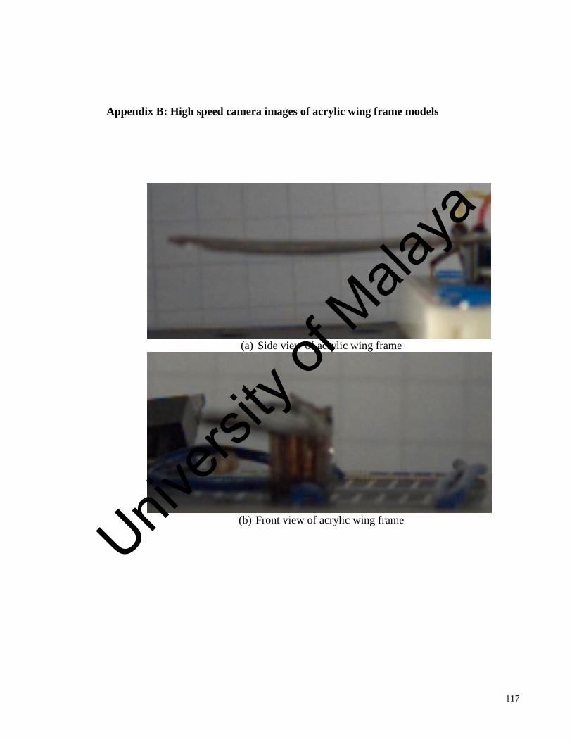
117
Appendix B: High speed camera images of acrylic wing frame models
(a) Side view of acrylic wing frame
(b) Front view of acrylic wing frame
Univers
ity of
Mala
ya

118
Appendix C: High speed camera images of ABS wing frame models
(a) Side view of ABS wing frame
(b) Front view of ABS wing frame
Univers
ity of
Mala
ya