Embed Size (px)
Citation preview
32D05HE2008 2.19173 DOKIS 010
MALAMUTE PROPERTY
Tannahill and Dokis Township
NTS 32D/5
48*24^79*38^ RECEIVED"JAN i \ 1593
GEOSCOCF ASSESSMENTliirk.E ^——.
Prepared by: Eric Marion
Index
Figure l - Location Map
Figure 2 - Claim Map
Location
Access
Claims
Geology
Figure 3 - Regional Geology
Figure 4 - Work Location Map
Work dong
Site "A
Site "B
Site "C
Figure 5- Site "A"
Figure 6- Site "B"
Figure 7- Site "C"
Trench "T-1
Prospecting Grid - OC-3
Figure 8- Trench - T-1
Figure 9 - OC-3
Conclusions
-Sample Description
Assay Sheets
-Base Map - (in pocket)
Section -B /' Geophysical Interpretation
32D05NE2008 2.19173 DOKIS 010C
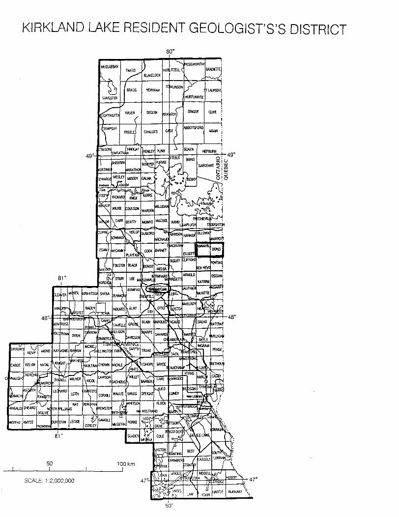
KIRKLAND LAKE RESIDENT GEOLOGIST'S'S DISTRICT
49"
SCALE: 1:2,000.000
^pBttis'sau— ,
1217543
— — — — —4
I20GIIQo
12223301 N j 12139194- -.- - H, i
l 1213918l
1217429
1213861
^--- -J"MINISTRY OF NORTHERN DEVELOPMENT
AND MINES ga
Minntry of Miriltry ol Nltml northern Dmekxxiwm
md Mms l K7M l UTN j M ALA MUTE
^ocation
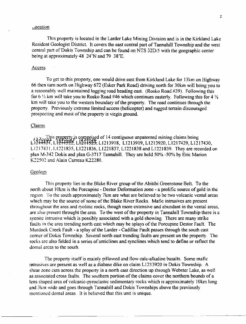
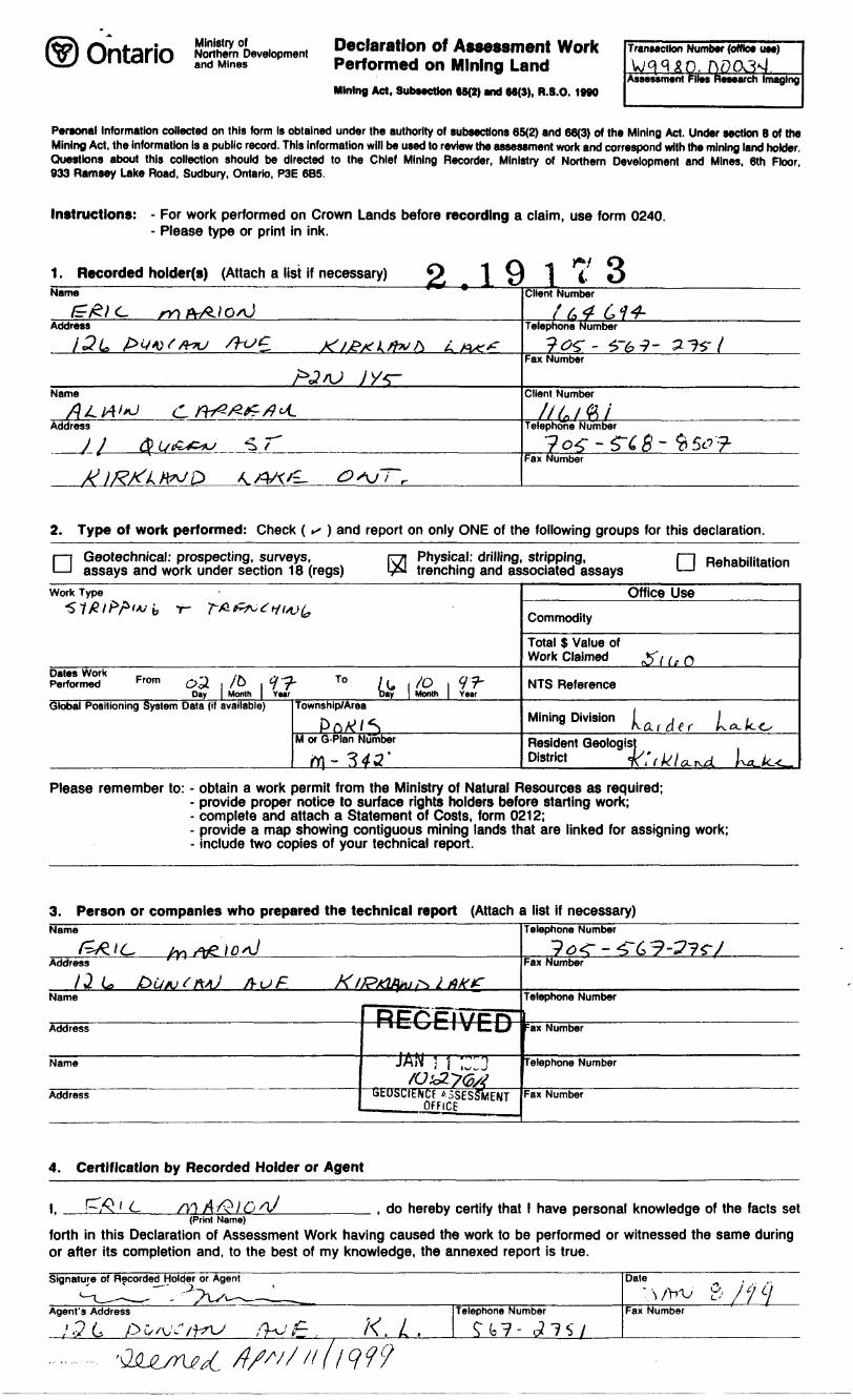
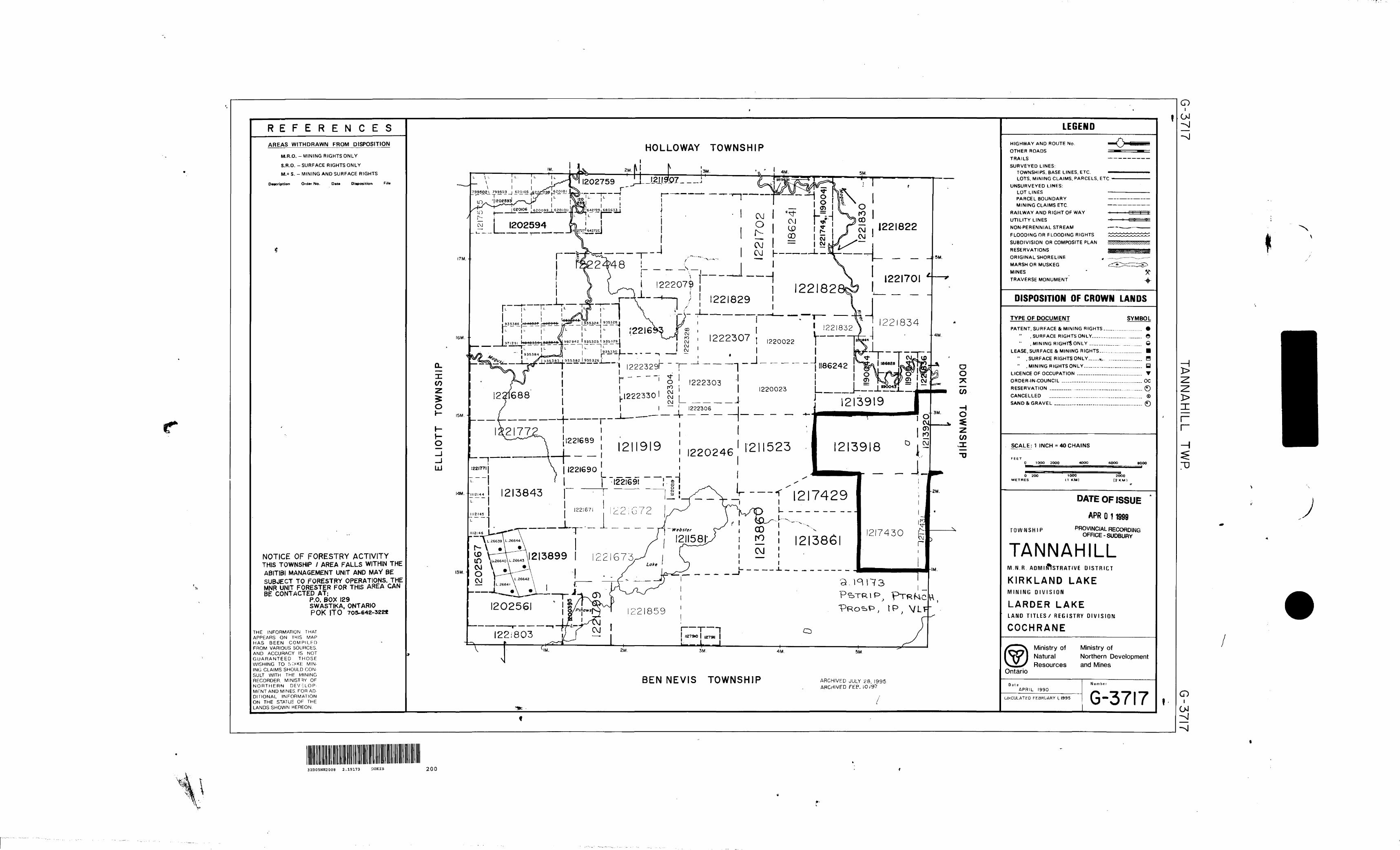
This property is located in the Larder Lake Mining Division and is in the Kirkland Lake Resident Geologist District. It covers the east central part of Tannahill Township and the west central part of Dokis Township and can be found on NTS 32D/5 with the geographic center being at approximately 48 24'Nand79 38'E.
Access
To get to this property, one would drive east from Kirkland Lake for 13km on Highway 66 then turn north on Highway 672 (Esker Park Road) driving north for 30km will bring you to a reasonably well maintained logging road heading east. (Rosko Road #39). Following this for 6 1/2 km will take you to Rosko Road #46 which continues easterly. Following this for 4 Vz km will take you to the western boundary of the property. The road continues through the property. Previously extreme limited access (helicopter) and rugged terrain discouraged prospecting and most of the property is virgin ground.
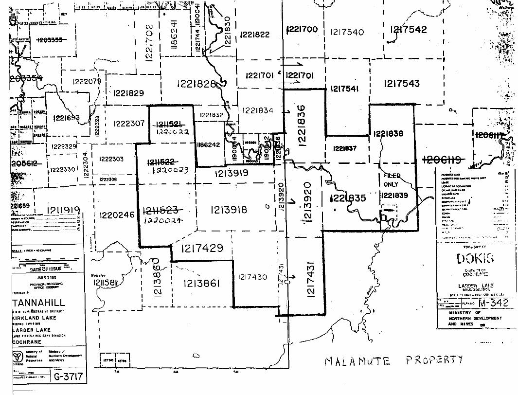
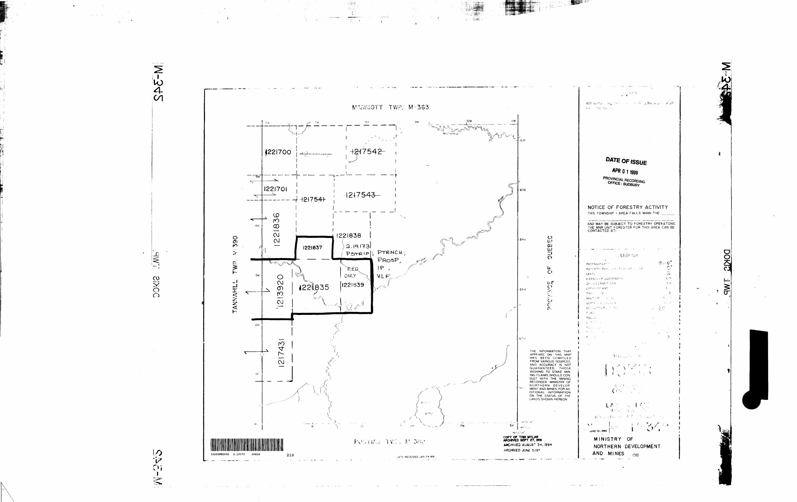
Claims
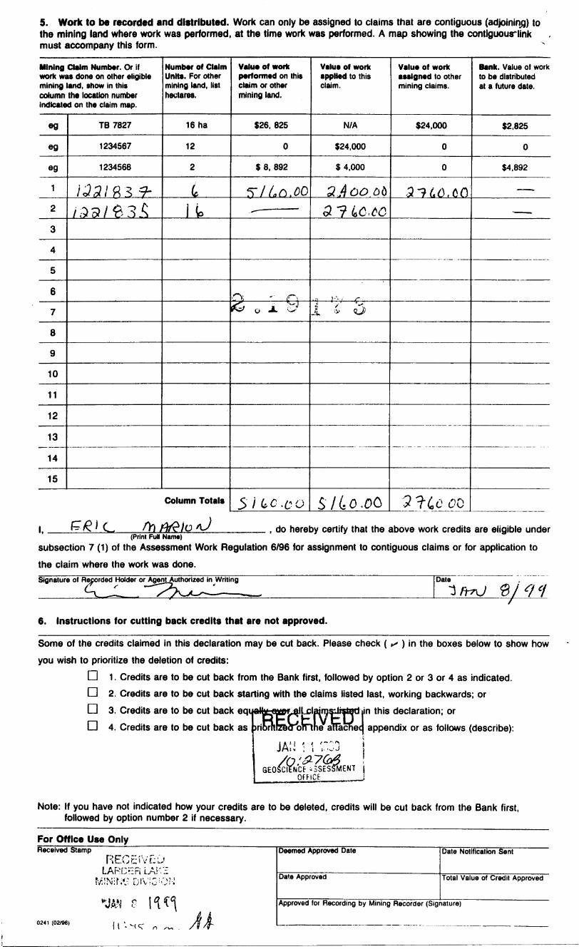
l i^OoSli' 5 *?3^ouSi';^ s SSF^RBF4* o^ ^ contiguous unpatented mining claims being L121I52T, L\2\\yl2, L1211523, L1213918, L1213919, L1213920, L1217429, L1217430, L1217431,L1221835,L1221836,L1221837,L1221838andL1221839. They are recorded on plan M-342 Dokis and plan G-3717 Tannahill. They are held 5007o -5007o by Eric Marion K22502 and Alain Carreau K22280.
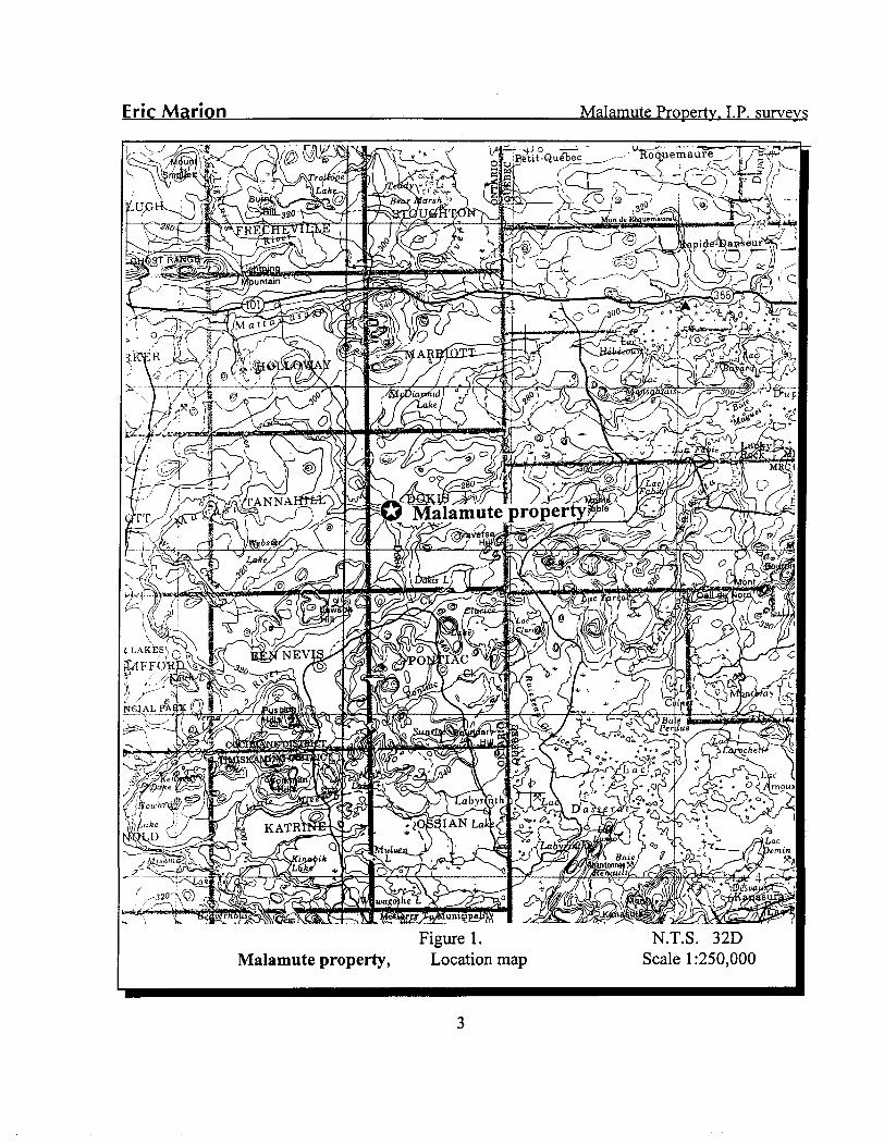
Geology
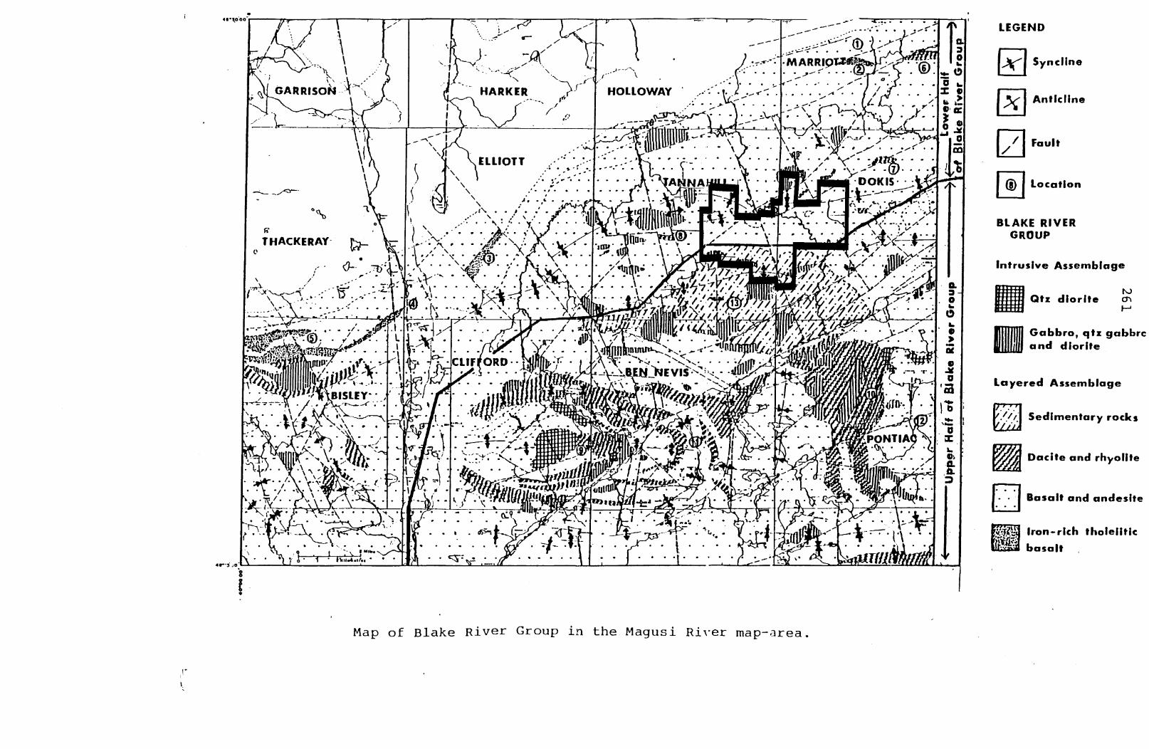
This property lies in the Blake River group of the Abitibi Greenstone Belt. To the north about 10km is the Porcupine - Destor Deformation zone - a prolific source of gold in the region. To the south approximately 7km are what are believed to be two volcanic vental areas which may be the source of some of the Blake River Rocks. Mafic intrusives are present throughout the area and ryolitic rocks, though more extensive and abundant in the vental areas, are also present throught the area. To the west of the property in Tannahill Township there is a syenite intrusive which is possibly associated with a gold showing. There are many strike faults in the area trending north east which may be splays of the Porcupine Destor Fault. The Murdock Creek Fault - a splay of the Larder - Cadillac Fault passes through the south east corner of Dokis Township. Several north east trending faults are present on the property. The rocks are also folded in a series of anticlines and synclines which tend to define or reflect the domal areas to the south.
The property itself is mainly pillowed and flow calc-alkaline basalts. Some mafic intrusives are present as well as a diabase dike on claim L1213920 in Dokis Township. A shear zone cuts across the property in a north east direction up through Webster Lake, as well as associated cross faults. The southern portion of the claims cover the northern bounds of a lens shaped area of volcanic-pyroclastic sedimentary rocks which is approximately 10km long and 3km wide and goes through Tannahill and Dokis Townships above the previously mentioned domal areas. It is believed that this unit is unique.
f ",'*V " " "^ V•l * x * * v * V^Y"i\* * **\' \ /ynlJ ,-•A - - - ^m^- y
w . \. .... .*jr.v.!\ - - ^* sri ——•—\*——'r-^—— C^:———^-^
LEGEND
Syncline
Anticline
Fault
Location
BLAKE RIVER GROUP
Intrusive Assemblage
NJQtz diorite en
fi Gabbro, qtz gabbro jjjl and diorite
Layered Assemblage
Sedimentary rocks
Dacite and rhyolite
'/'t
- - l Basalt and andesite
Iron-rich tholeiitic
basalt
Map of Blake River Group in the Magusi River map-area.
\ -\--_L -~
• * jBlnnut K t/J
V/ l 0 *S
;!Lr~ 4B^s^-
Work Done
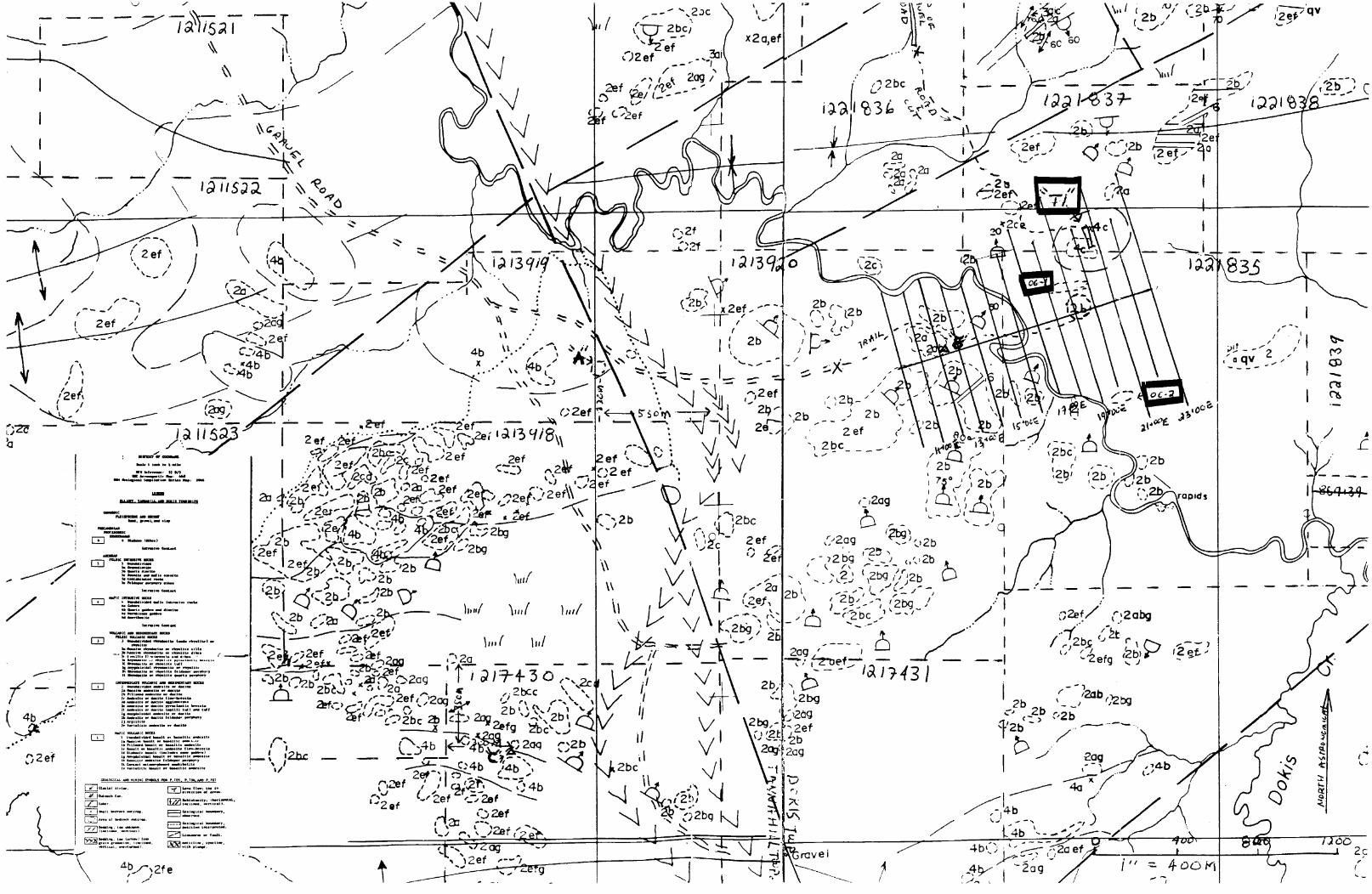
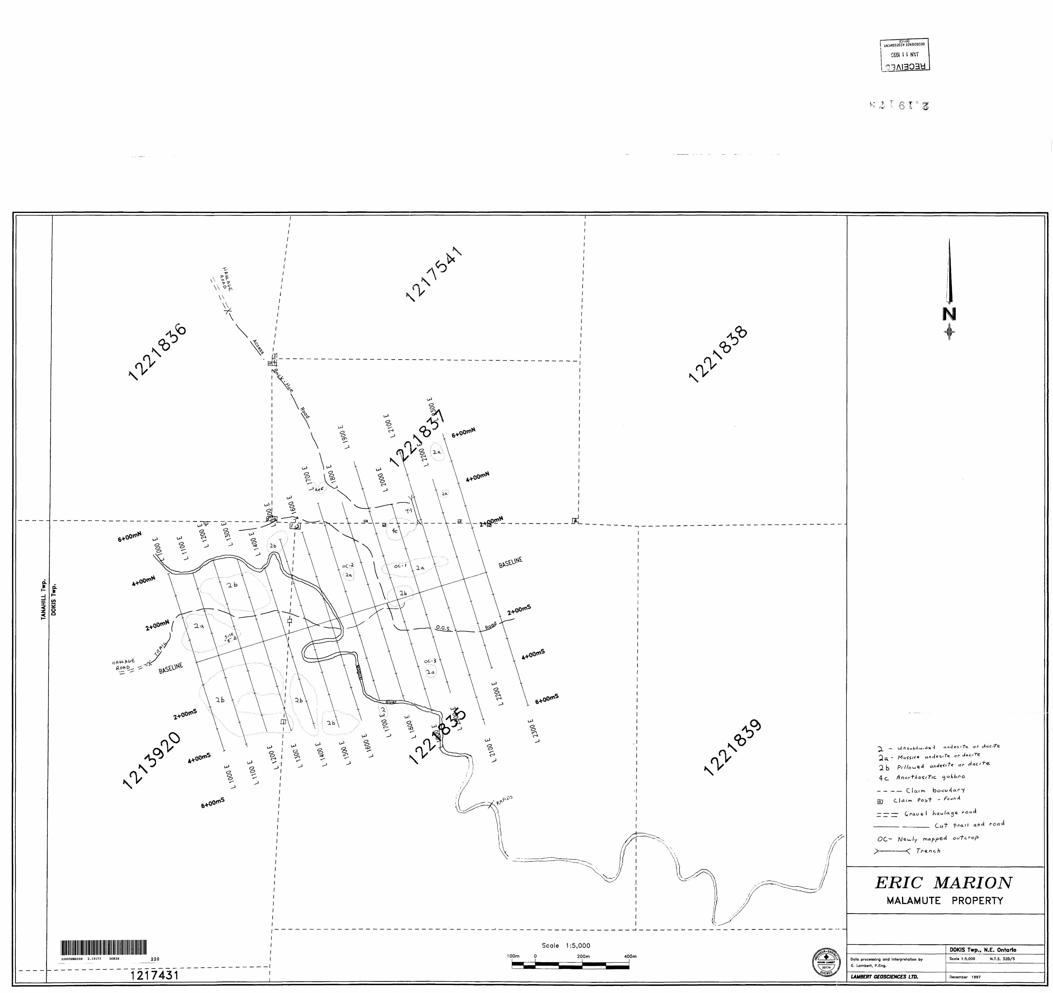
During the past season, a 14km grid was cut and a VLF survey was performed. An I.P. survey was done on the eastern area of the grid. A road was cut and a trench dug by a back hoe in the area of a mildly anomalous I.P. response (Tl).Prospecting on the area of the grid east of the Magusi River has outlined three new outcrops previously unmapped (OC-l/OC-3) as well limited stripping and digging was done in three areas found in prospecting traverses. (Site A, Site B and Site C )
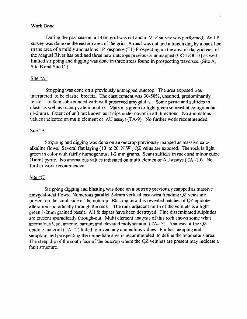
Site "A"
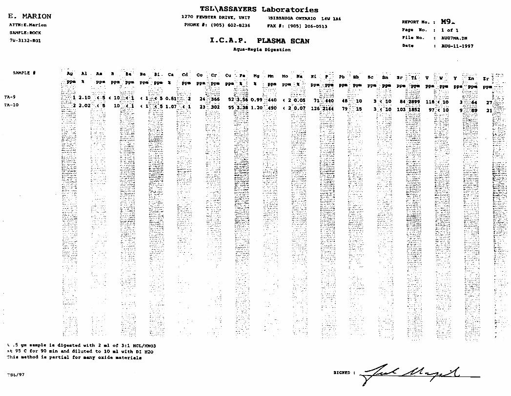
Stripping was done on a previously unmapped outcrop. The area exposed was interpreted to be clastic breccia. The clast content was SO-50%, unsorted, predominantly felsic, l to 8cm sub-rounded with well preserved amygdules. Some pyrite and sulfides in clasts as well as scant pyrite in matrix. Matrix is green to light green somewhat equigranular (l-2mm). Extent of unit not known as it dips under covor in all directions. No anomalous values indicated on multi element or AU assays (TA-9). No further work recommended.
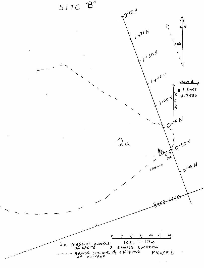
Site "B"
Stripping and digging was done on an outcrop previously mapped as massive calc- alkaline flows. Several flat laying (10 to 20 N.W.)QZ veins are exposed. The rock is light green in color with fairlly homogenous, 1-2 mm grains. Scant sulfides in rock and minor cubic (1mm) pyrite. No anomalous values indicated on multi elemen or AU assays (TA-10). No further work recommended.
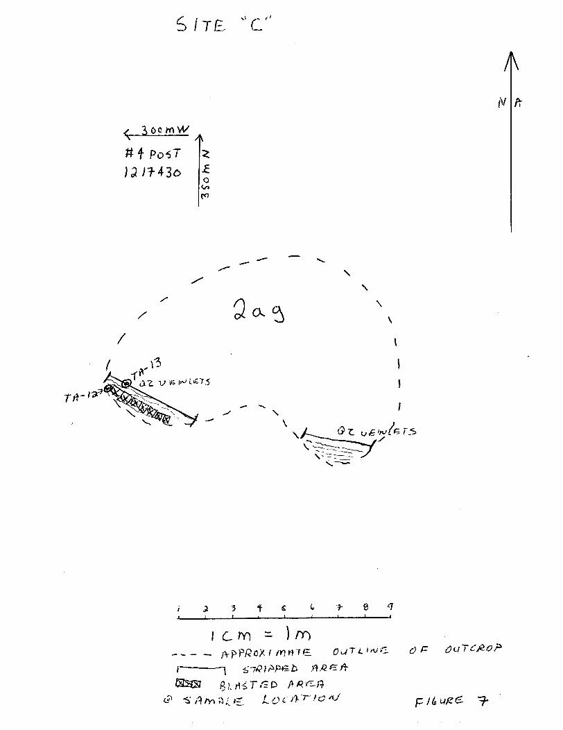
Site "C"
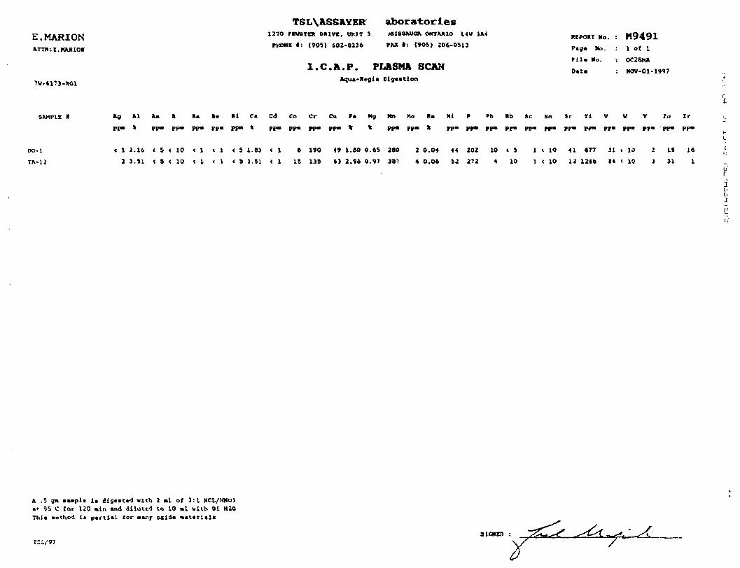
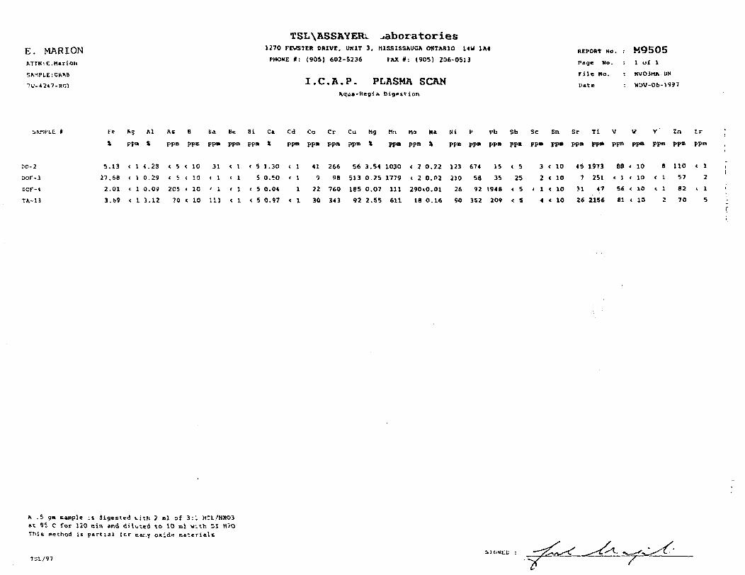
Stripping digging and blasting was done on a outcrop previously mapped as massive amygdaloidal flows. Numerous parallel 2-4mm vertical east-west trending QZ veins are present on the south side of the outcrop. Blasting into this revealed patches of QZ epidote alteration sporadically through the rock . The rock adjacent north of the veinlets is a light green l-2mm grained basalt. All feldspars have been destroyed. Fine disseminated sulphides are present sporadically through-out. Multi element analysis of this rock shows some what anomalous lead, arsenic, barium and elevated molybdenum (TA-13). Analysis of the QZ epidote material (TA-12) failed to reveal any anomalous values. Further mapping and sampling and prospecting the immediate area is recommended, to define the anomalous area. The steep dip of the south face of the outcrop where the QZ veinlets are present may indicate a fault structure.
S J 71 "A"
( 9*l
} 4 TP/'V'^'^
^ - -
T 1-— ̂
*.-\
\i
11 SSoro T\
s
.s-b'l /ais^/^i? _ . .^
-fc^— J \v \v \
SO
O
/
Se
f
l C ry\
X' 6 ^
\
N.X
X
:f
\ 4
X
r
i.* o v
O
o .-o ac. 3^
^nwc. Ac F o -ir e fro P
S/TE "C"
x 3t6Q H\W \
#f Po^T J3/7-436
/
V is (^ i'S.I'5
N
\\
\
\\
O Z. u&i^L^TS.
i 2
r
ts t ?- e ^
- mO
Trench "Tl"
Approximately 1.5 km of road was cut to allow access for an excavator to dig a trench in an area of a mildly anomalous I.P. respose marked by a slight phase shift and resistivity. This trench was on the north flank or an outcrop previously mapped as anorthositic gabbro. The trench was 85 meters long by an average 2.5 meters wide. The sandy unsorted coarse till had an average depth of appoximately 3 meters. After cleaning the trench the bedrock was observed to have no significant mineralization to account for the IP response. A region at approximately 3+62 N was seen to have a visibly larger crystal structure (2-3mm) which could reflect internal zowing of the mafic intrusive. All rock exposed was Gabbro. The weak IP response has not been correlated to any apparent bedrock source. Two samples, one of the coarse grained gabbro (DO-2) and of the fine grained (DO-1) failed to reveal any anomalous values. No further work is recommended in this area.
Two noteworthy pieces of float were found. The first DOF-3 was a 40cm block of massive pyrite (SO-90%) which showed elevated copper. The second DOF-4 is a sub-rounded piece of white quartz with galena and sulfides present. Assay results showed anomalous arsenic lead and molybdenum values. Prospecting up ice of this trench might reveal their source.
Prospecting - Grid
Prospecting the out crop exposed on the grid failed to reveal any interesting alteration or mineralization, however, three new outcrops were mapped east of the Magusi River. The first, north of the baseline (OC-1) is seen to be a ledge about l meter high running intermittently across three grid lines, facing south. The northern extent of this unit dips under cover. The rock is massive flow basalt, 1mm grained, medium green. No mineralization or alteration was observed but this lineament may represent a fault. An isolated outcrop (OC2) approximately 100m west, may belong to the same unit as the same rock type was observed here.
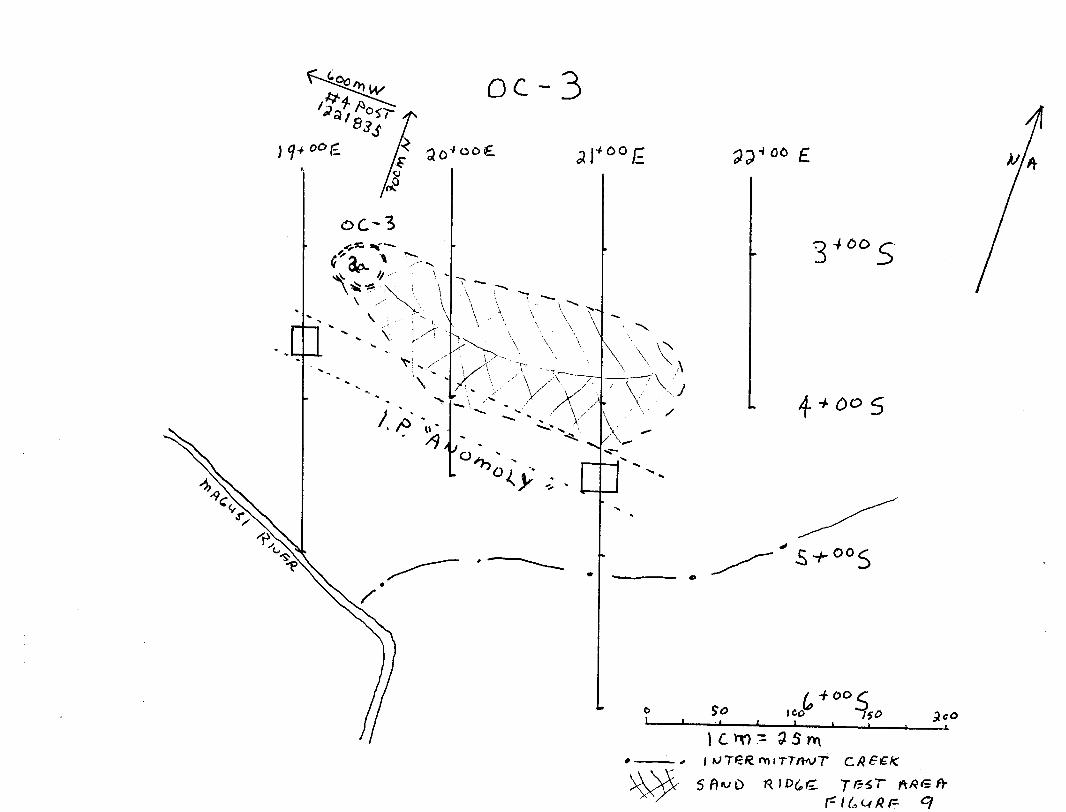
The third outcrop (OC-3) is at the southern end of the grid east of the Magusi River, between 19+OOE and 20+OOE, at about 3+25S. This rock is interpreted to be massive andesite to dacite. Color is light grey green to green with 1-1 Y2 mm grains. Although this area corresponded somewhat with a weak I.P. response, prospecting around it failed to yield any encouraging mineralization or alteration. A coarse sandy ridge extends to the east from this outcrop. A series of probe holes made by hammering a steel bar into the overburden to a depth of about l .2m was done over this ridge at about 25 meter intervals in an attempt to locate a bedrock extension, in the belief that this sand ridge concealed a bedrock feature. No bedrock was located but a few boulders were noted. To the west of the outcrop area, the topography dips into a low lying scrub brush area which flanks the Magusi River. Recommendation: Mechanical trenching on the south side of the outcrop area may possibly expose the cause of the IP "anomaly". As well mechanical trenching down the ridge from the outcrop in a selected area corresponding with the anomaly may yield results.

\
l MS —————————— - ———— ————— - ————— —————————— — —— — - — —-^^ _ /!\
\ "M -. - . -. . .. t -T i ^•^ '' ^
1 l * t I *^
(^ ^ if* Oi
5 * * i ^ ^ * ^
r
— — . 4-i./AJfZ i
-**
J
3 y 'itf (S/
s j D e.
CO
TO
oc-3
o 460 {~
4 + tfo 5
±J^—~~—L.^—^—^.
l c MO - 3 s
Conclusions
The collar of the OGS hole has not been located to date. The access road which was made for this program, has been mapped onto my grid. It was hoped an IP response would correlate with this road. Correspondence this fall with the OGS Geologist who oversaw this program (K. G. Steele), has revealed that the OGS hole (88.39) is most probably further east than previously anticipated due to a discrepancy between the aerial photographs used in the program and the maps that were ultimately submitted to the Ministry with the final reports.
It would be most important to extend the grid further east and do more geophysical work, especially an IP survey, to locate the alteration zone represented in the OGS hole. The significance of this sericite - carbonate alteration can not be overstated. Perhaps then a drill target may be better defined, and the response tracked back to the original survey. The anomalous response in the region of OC-3 should be followed up with trenching or perhaps soil sampling in order to better define a source. More prospecting and perhaps stripping and sampling should be done in the region of Area "C" in order to evaluate the elevated values present inTA-13
Samples
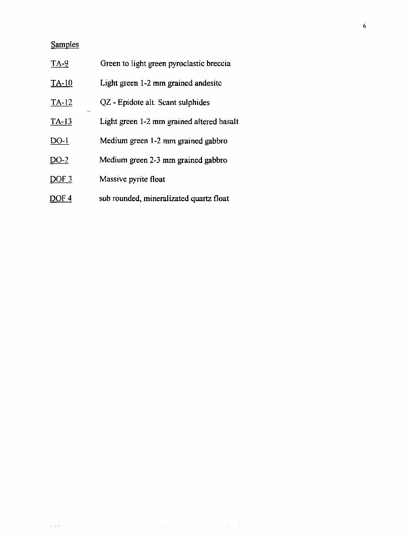
TA-9 Green to light green pyroclastic breccia
T A-10 Light green 1-2 mm grained andesite
TA-12 QZ - Epidote alt. Scant sulphides
T A-13 Light green 1-2 mm grained altered basalt
DO-1 Medium green 1-2 mm grained gabbro
DO-2 Medium green 2-3 mm grained gabbro
DOF3 Massive pyrite float
DQF4 sub rounded, mineral izated quartz float
Swastika LaboratoriesA Division of TSL/Assayers Inc.
Established 1928 Assaying - Consulting - Representation Geochemical Analysis Certificate
Company: E. MARIONProject:Attn: E. Marion
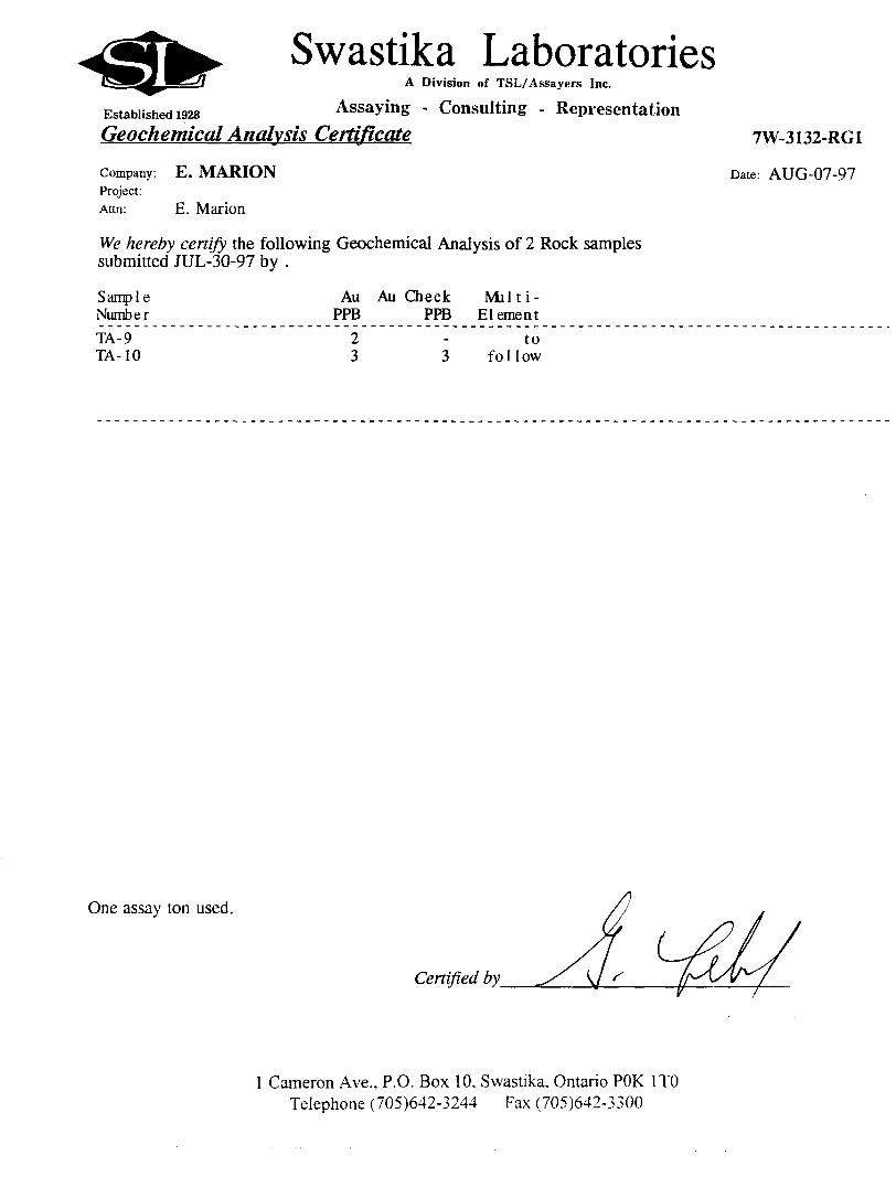
We hereby certify the following Geochemical Analysis of 2 Rock samples submitted JUL-30-97 by .
7W-3132-RG1
Date: AUG-07-97
Sampl e Number
Au PPB
Au Check PPB
Milti- Element
TA-9 TA-10
23
to follow
One assay ton used.
Certified by
l Cameron Ave., P.O. Box 10, Swastika. Ontario POK l TO Telephone (705)642-3244 Fax (705)642-3300
E. MARIONMTN:E.Marion
SAMPLE: ROCK
7W-3132-R01
TSL\ASSAYERS Laboratories1270 PEW3TER DRIVE. UNIT
PHONE *: (905) 602-8236
13I33AUOA ONTARIO L4U 1A4
PAX f: (905) 206-0513
I.C.A.P. PLASMA SCANAqua-Ragia Digestion
REPORT Mo. : M9*
Pag* Ho. : l of l
PH* Mo. : AU07HA.DN
Data ! AOO-11-1997
SAMPLE * Ag Aipp* *
S12 - 10?::.v2 2.02i
Aa
PP"
B Ba
PP" PP-
Ba Bi
ppm pp.
Ca Cd Co ycr . Cu -.' Pa ; Mg Mn Mo Ma Ml
\ PP- ppmv
t~-'- Pb 8b
'^~
PP" :;;*;! * :- PP*g-:-:*: ;:v; :.r;v-
* 1.20.:490
PP* ;;pp" PP"; PP"
15
Se Sn
PP" PP*
3 V 10
3 :rib
sr ]-~1i : PP" rPP-
84 2899
103'Il852
V (W Y
PP* J PP- PPIn Z r
m
\ .5 ga aanple la dlgaatad with 2 "l of 3:1 HCL/KNO3 it 95 C for 90 mln and dllutad to 10 "l with DI H2O Thia method la partial for eany oxida material*
T3L/97 SIGNED
Swastika LaboratoriesA Division of TSL/Assayers Inc.
Established 1928 Assaying - Consulting - Representation
Geochemical Analysis Certificate 7W-4173-RG1
Company: E. MARION Date: OCT-27-97Project:Attn: E. Marion
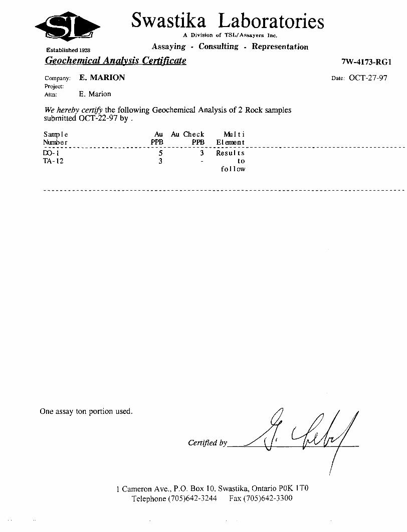
We hereby certify the following Geochemical Analysis of 2 Rock samples submitted OCT-22-97 by .
Sample Au Au Check Mil t i Number PPB PPB ElementDO-1 5 3 Results TA-12 3 - to
fo 11ow
One assay ton portion used.
Certified by
l Cameron Ave., P.O. Box 10, Swastika, Ontario POK l TO Telephone (705)642-3244 Fax (705)642-3300
E.MARIONKTTH:t.HUtIOH
7U-4173-RC1
SAMPLE
DO-1
TA-12
TSL\ASSAYER127O riwsirn omvr. utijr 3.
PHONC t: (90S) 60Z-ej36
aboratorles/31S3MIO* ONTMIO L4U 1A4
PM l: (905) 206-0513
I.C.A.P. PLASMA SCAN
Ag hi
ppn *
B km B* li Ci Cd CO Cr Cu P*
PP" PP* FP* PP" * PP* PP" PP" PP" *
Hg *
Mn Mo Ra
PP* PP" *
Hi P Pb ab
PP- PI* PP* PP-
Se
HEPORT Ho.
P lg t Ho.
rU* No.
D* C*
Sn Sr Ti
PP* PP- PP"
M9491l o( l
OC28HA
HCW-Ol-1997
V Y lv Ir
PP- PP- PP" PP"
1 2.16 x 5 * 10 f l ij
2 3.5: ( 9 ( 10 < l (l
5 1.6) (l a 19O 49 I.eO 0.65 280
9 3.51 < l 15 139 6) 2.Si 0.97 3B1
2 0.04 44 202 10 t 5
4 0.06 52 272 4 10
l t 1O 41 677 31 t 10 2 19 16
l i 10 12 1246 84 * 10 3 31 l
r i
h .5 ja tuple i. digested with J -V of 3:1 HCL/HMo) i- 95 C for 120 kin and diluted to 10 ml with DI H2O Thi* at t hod It partial for m*r.j oxide tcri.fls
SIGNED
Swastika LaboratoriesA Division of TSL/Assayers Inc.
Established 1928 Assaying - Consulting - Representation Geochemical Analysis Certificate
Company: E. MARIONProject:Attn: E. Marion
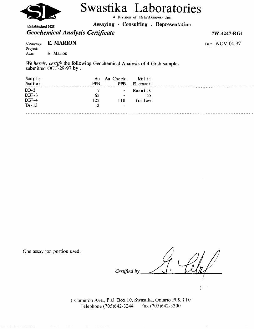
We hereby certify the following Geochemical Analysis of 4 Grab samples submitted OCT-29-97 by .
7W-4247-RG1
Date: NOV-04-97
SampI e Number
Au PPB
Au Check PPB
Mil 11 Element
DO-2 DOF-3 DOF-4 TA-13
765
1252
110
Resultsto
fo 11ow
One assay ton portion used.
Certified by^
l Cameron Ave., P.O. Box 10, Swastika, Ontario POK l TO Telephone (705)642-3244 Fax (705)642-3300
E. MARIONATTN:E. Marion
7U-4H7-R01
TSL\ASSAYERw jaboratories1270 FEVSTER DRIVE. UK IT 3. HISS1SSAUCA OBTARIO L4W 1A4
PHONE *: (905) 602-6236 FAX #: (905) 206-0513
I.C.R.P. PLASMA SCANAqua-Regia Digestion
REPORT Mo.
Page No.
File Ho.
Date
M9505l of l
HUO3MA UN
NOV-Ob-1997
t e Rg Al he B Ba Be Bi Ca
t ppm S ppn ppe ppn ppo ppo SCd Co Cr Cu Mg
ppi* ppm ppm ppm X
Mn Ho Na Hi P Pb Sb Se Sn Sr li V W Y Zn Ir
ppm ppn k PF* PP" PP" PP" PP* FP" PP" PP* PF"1 PP" PPn PP" PP"1
00-2
Dor-3DOF-l
TA-13
5.13 i l 4.23
27.58 i l 0.232.01 * l 0.093.09 < l 3.12
< 5 < 10 31 ( l ( 5 1.30 i l 41 266 66 3.54 1030 ( 2 0.22 123 674 15
< 5 < 10 (l t l 5 0.50 < l 9 98 513 0.25 1779 < 2 0.02 210 58 35
205 i 10 'l < l (S 0.04 l 72 760 165 0.07 111 290.0.01 26 92 1948
70 ( 10 113 (l < 5 0.97 i l 30 343 92 2.55 611 18 0.16 SO 352 2O9
i
4
<
5
25
B
9
3
2i 1
4
( 10
< 10
< 1O
* 10
45
7
M
26
1973
251
47
2156
eax 1
56
81
' 10
1 10
< 10
( 13
8
< 1
t 1
2
110
57
82
70
< 1
2
i 1
5
A .5 git t atop l e ;s digested i-ith 2 nl of 3:: HCL/HNO3 at. 95 c for 120 cin and dili,;ed to 10 ml with SI H2O ThiB method IE partial Icr n.ar.y oxid"? materiale
TSL/97
GERARD LAMBERTConsultation et genie-conseil en geophysique.
ERIC MARION
Malamute Property
Dokis Township, N.E. Ontario
N.T.S. 32D/5
Report on V.L.F. - E.M. and Induced Polarization surveys
Rouyn-Noranda, Quebec Gerard Lambert, P.Eng.
December 19, 1997 Consulting Geophysicist
144, rue George. C.P. 2355, Rouyn-Noranda (Quebec) Canada J9X 5A9 Tel.: (819) 762-3182 Fax: (819) 762-5364
Eric Marion___________________________Malamute Property. I.P. surveys
TABLE OF CONTENTS
Introduction ........... ........ ......... . 2
Property description, location, access ......... 2
Description of the VLF and I.P. surveys........ 6
Results and interpretation ................... 8
Conclusion and recommendations ............ 12
Appended:Scale
V.L.F. - E.M. profiles .................. 1:5,000
Resistivity l I.P. pseudo-sections ......... 1:5,000
Apparent resistivity contour maps withI.P. anomalies superimposed ............. 1:5,000
Polarization (I.P.) contour maps withI.P. anomalies superimposed ............. 1:5,000
Eric Marion____________________________Malamute Property. I.P. surveys
Introduction
During the month of August 1997, ground geophysical investigations, consisting namely
in VLF-EM and Induced Polarization (I.P.) surveys, were carried out on the Malamute
property for prospector Eric Marion of Kirkland Lake.
The purpose of these surveys was to provide appropriate geoscientific information about
the underlying lithologies and tectonic structures and to map with a better accuracy the
distribution of disseminated and stringer sulfides in the bedrock, these sulfides being potentially
of economic interest if they are found to carry significant concentrations of base and/or precious
metals. Considering the lack of adequate I.P. coverage from past exploration work, the present
I.P. surveys were also meant to complement the geophysical knowledge of the property.
This report describes the work done and discusses the results obtained and the
interpretation of the data. Recommendations for any future work are presented in the conclusion.
The VLF survey was done by Eric Marion, whereas the I.P. survey was carried out by
crews of Remy Belanger Geophysics of Rouyn-Noranda, Quebec.
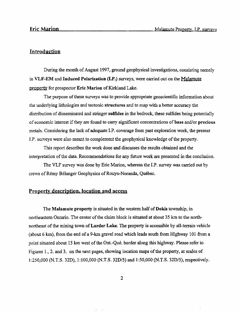
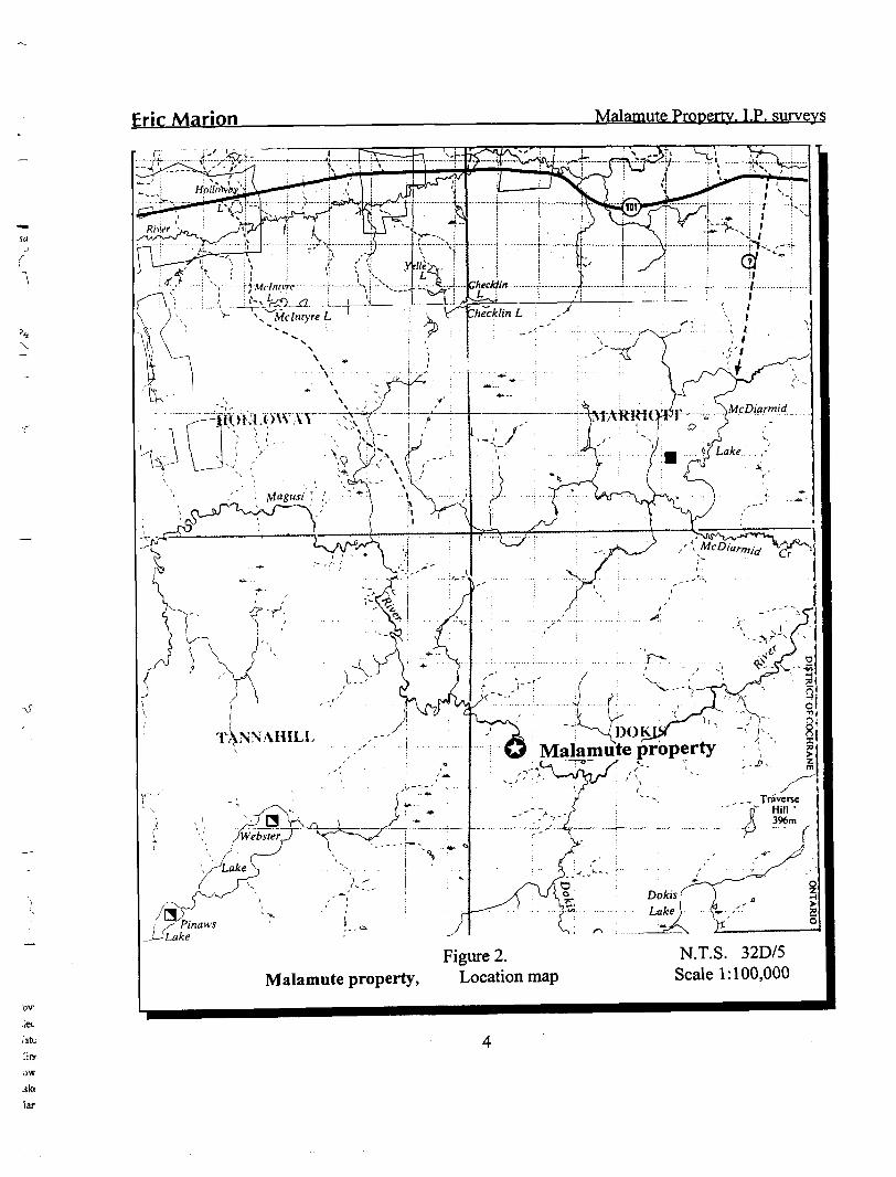
Property description, location and access
The Malamute property is situated in the western half of Dokis township, in
northeastern Ontario. The center of the claim block is situated at about 35 km to the north-
northeast of the mining town of Larder Lake. The property is accessible by all-terrain vehicle
(about 6 km), from the end of a 9-km gravel road which leads south from Highway 101 from a
point situated about 15 km west of the Ont.-Que. border along this highway. Please refer to
Figures l., 2. and 3. on the next pages, showing location maps of the property, at scales of
1:250,000 (N.T.S. 32D), 1:100,000 (N.T.S. 32D/5) and 1:50,000 (N.T.S. 32D/5), respectively.
Eric Marion Malamute Property. I.P. surveys
A, or __' RO
Malamute property
Figure 1. Malamute property, Location map
N.T.S. 32D Scale 1:250,000
Erie Marion Malamute Property. I.P. surveys
f
'ov
:iet .'alt lim ow ski lar
1)OK Maiamute property
N.T.S. 32D/5 Scale 1:100,000
Figure 2. Malamute property, Location map
Fric Marion Malamute Property. I.P. surveys
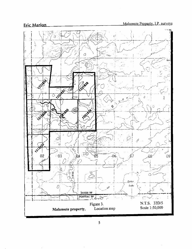
Figure 3. Malamute property, Location map
N.T.S. 32D/5 Scale 1:50,000
Eric Marion____________________________Malamute Property. I.P. surveys
The Malamute Property consists of five contiguous unpatented mining claims, situated
in the western half of Dokis Township. The map shown on Figure 4., next page, illustrates the
position of the survey area and some claim numbers. The VLF and I.P. compilation maps
appended to this report also show the claim boundaries, the claim lines and the claim numbers.
The geophysical surveys covered the following claims: 1221837 (6 units), 1221835 (16 units)
and 1213920 (16 units).
Description of the geophysical surveys
The geophysical surveys were carried out over a grid of fourteen (14) previously cut
picket lines oriented at 342 0 , spaced every 100m and chained/picketed every 25m between
6+OOS and 6+OON. The grid lines were turned off from base line 0+OOmN (Azimuth 0720 true).
The grid lines extend between L-10+OOmEand L-23+OOmE.
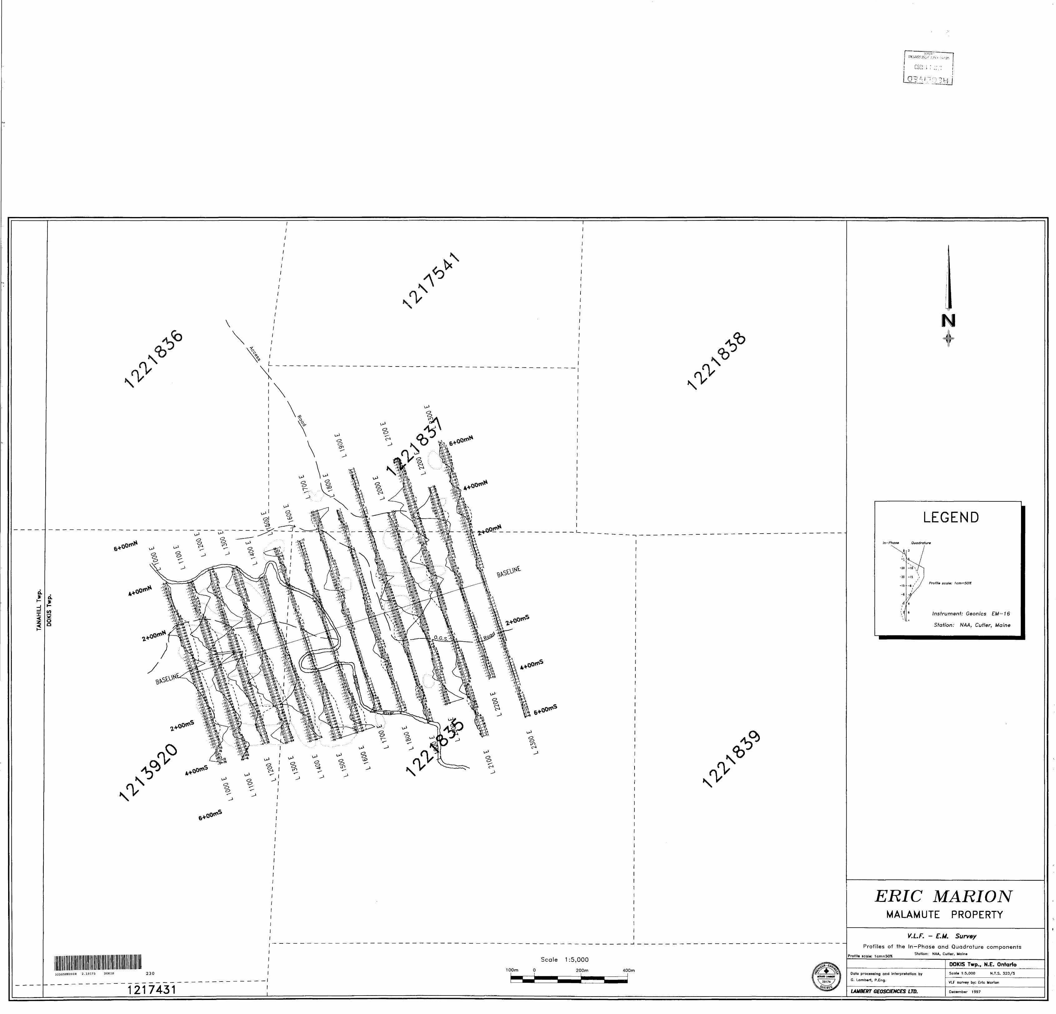
The VLF-EM survey was conducted along all the survey lines, using a Geonics EM-16
V.L.F. receiver, capable of reading the In-phase and Quadrature fields with a precision of ±1
percent. Readings of the secondary VLF field were taken every 12.5 meters. The field
measurements consisted in reading the tilt angle (in-phase) and quadrature components of the
VLF field from station NAA, Cutler, Maine, operating at 24.0 kHz. The operator was facing
toward the north during the measurements. No corrections were made to the field data.
The results of the VLF-EM survey are presented on the map appended to this report, at a
scale of l :5,000. Posted readings and In-Phase/Quadrature profiles are presented on this map.
A total of approximately 12.6 line-km of VLF-EM data was gathered by operator Eric
Marion, during the course of this survey.
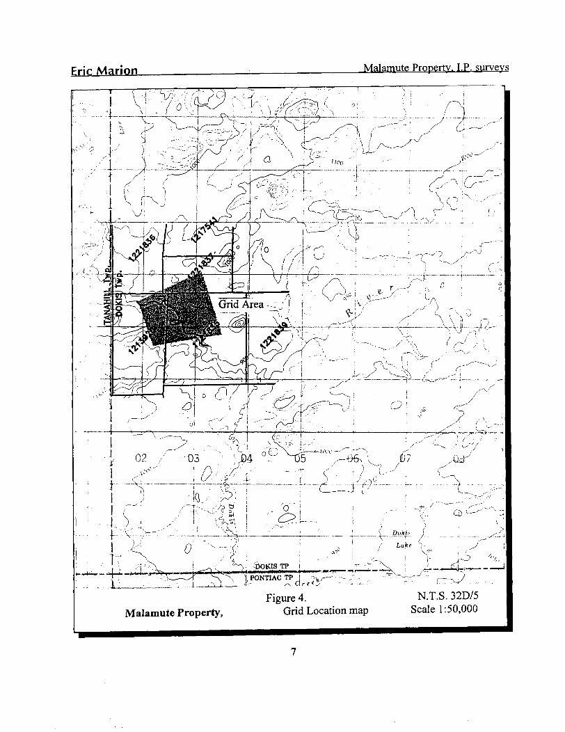
frlc Marion Malamute Property. I.P. surveys
Grid Area--: 'f r.A'
Malamute Property,Figure 4.
Grid Location mapN.T.S. 32D/5
Scale 1:50,000
Eric Marion____________________________Malamute Property. I.P. surveys
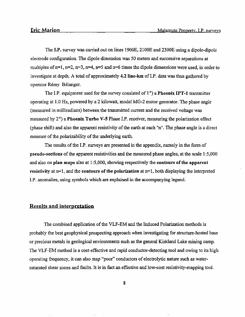
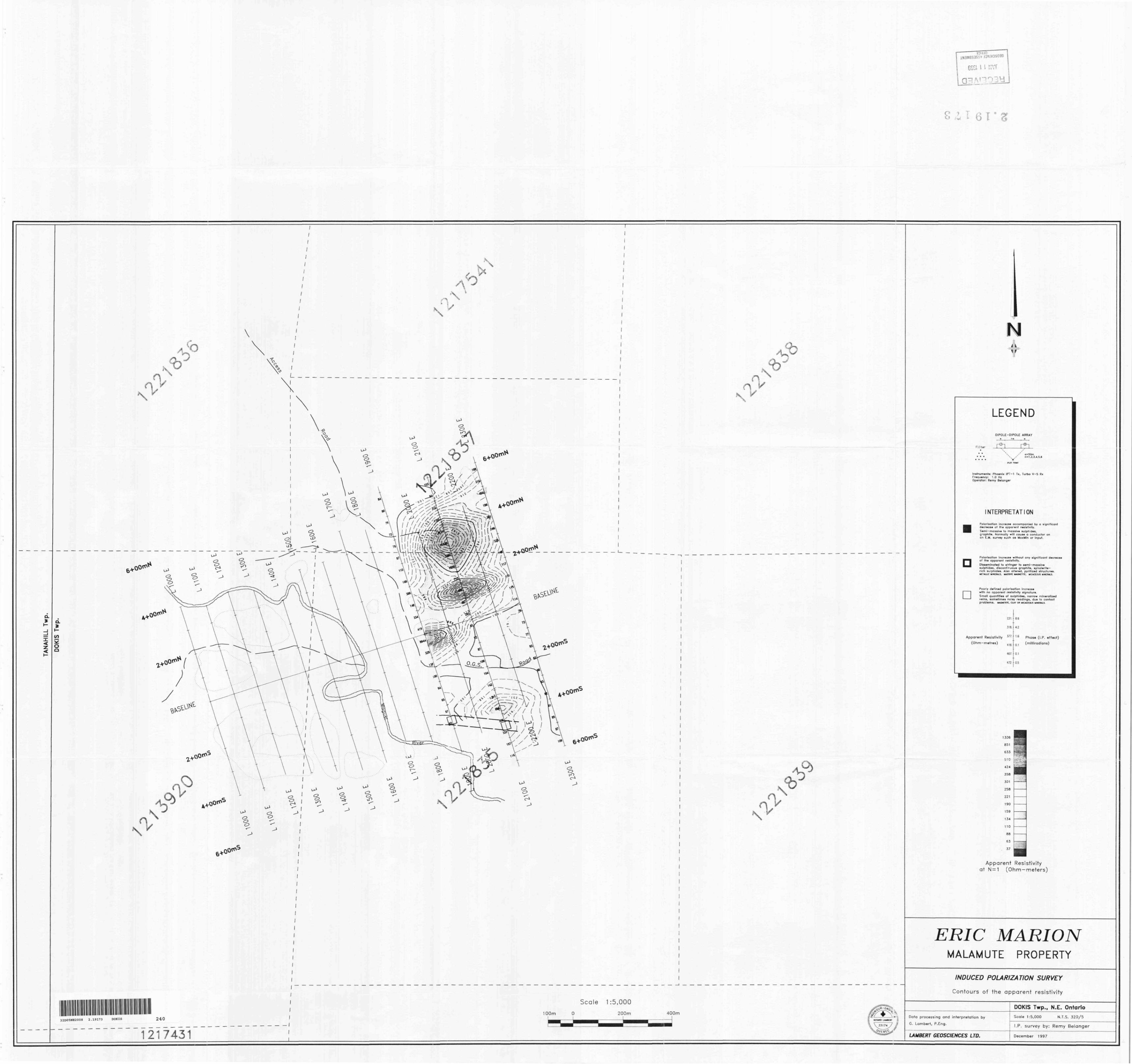
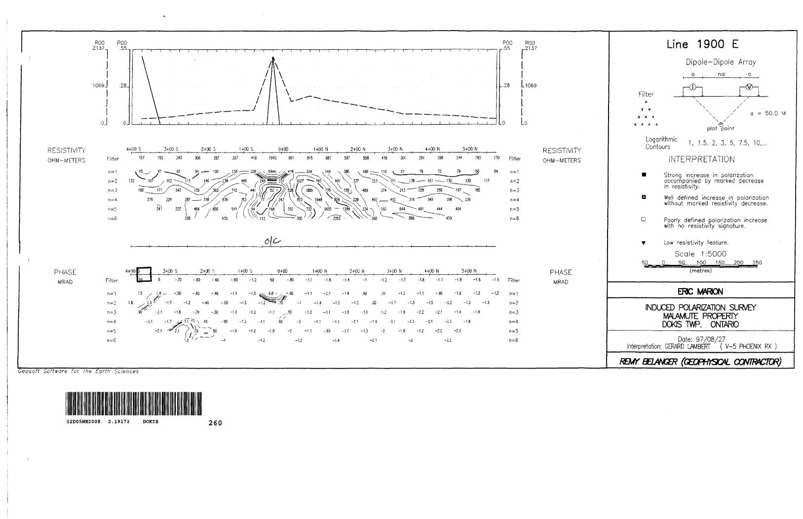
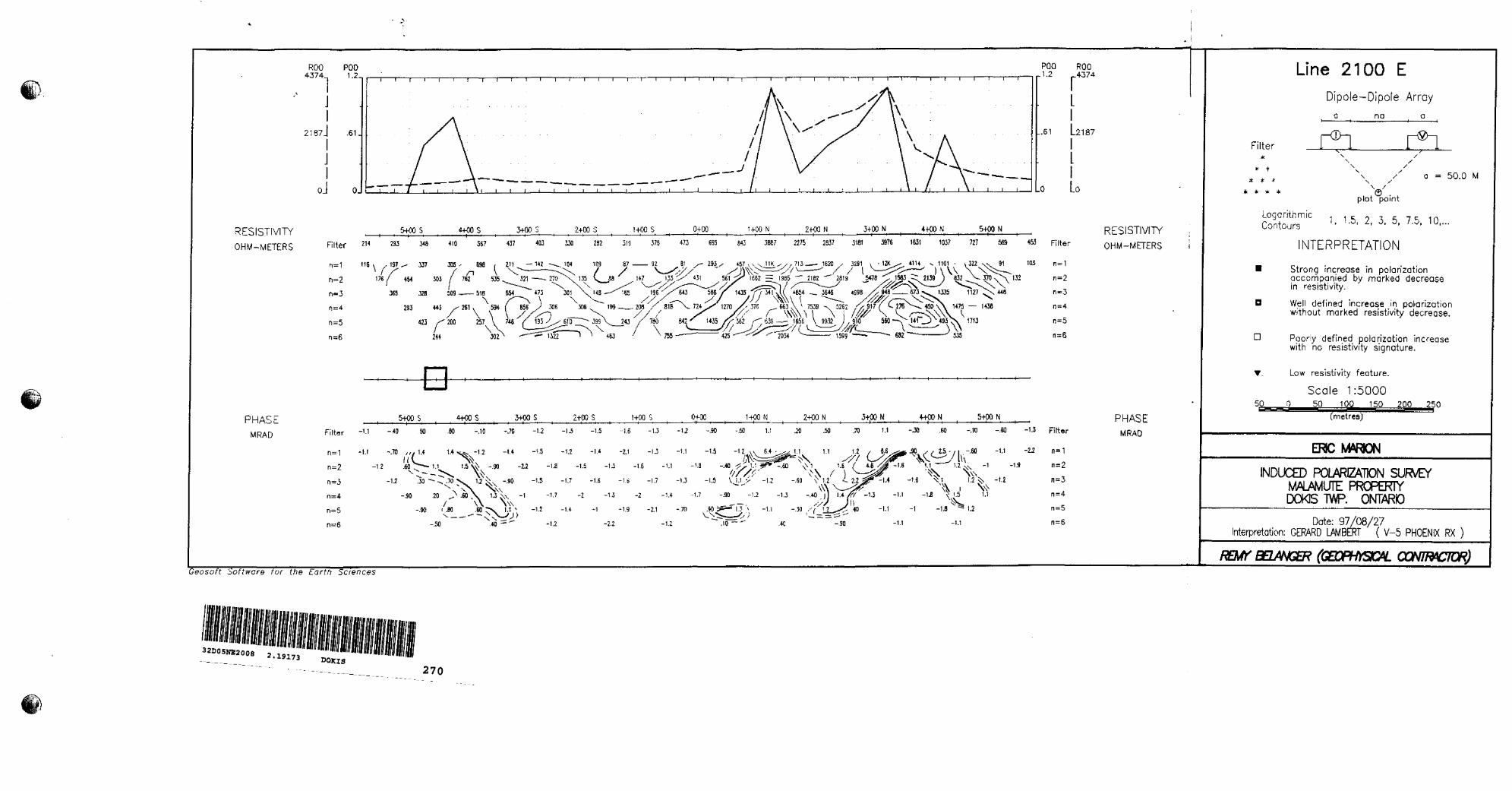
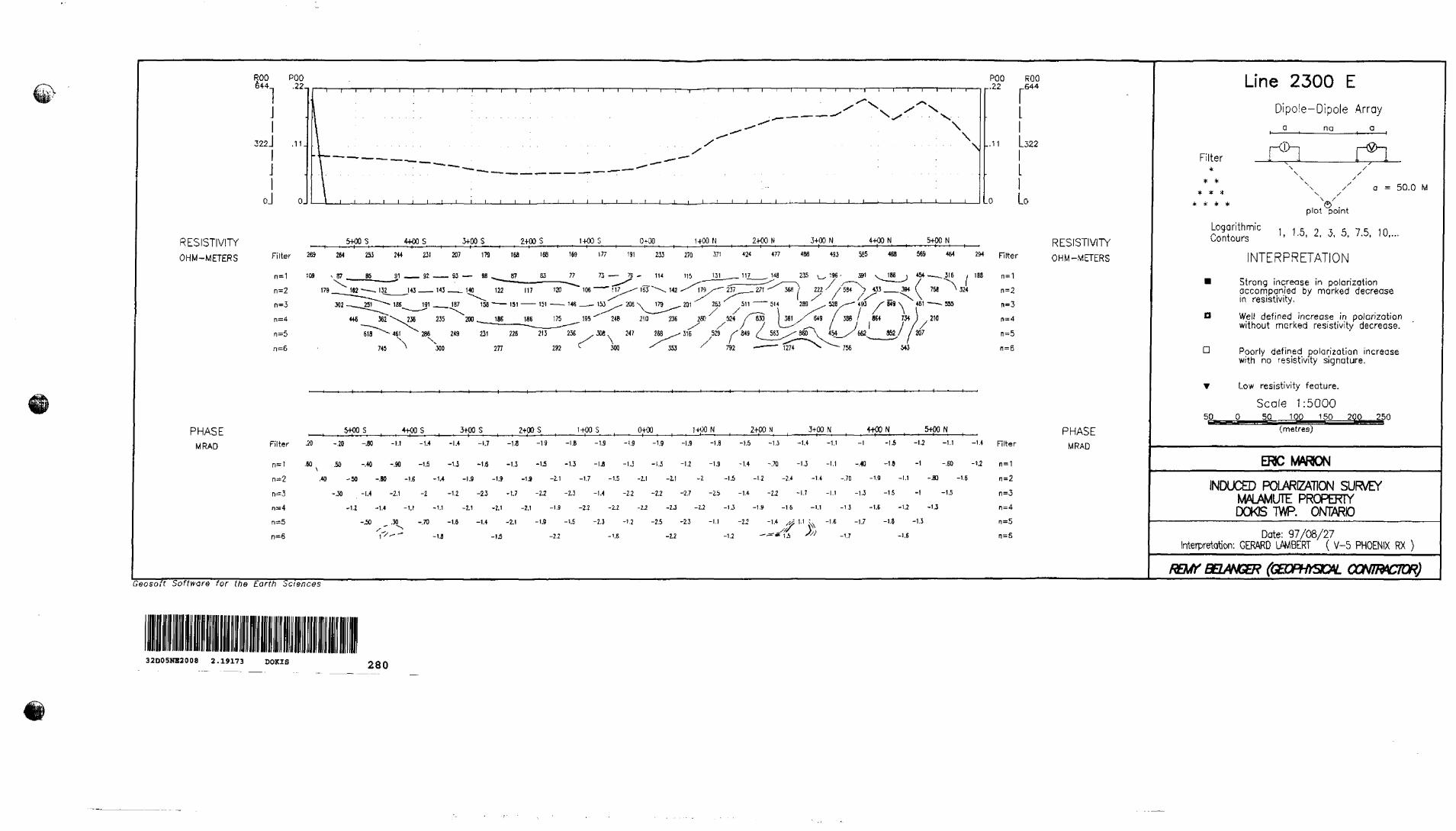
The I.P. survey was carried out on lines 1900E, 21 GOE and 2300E using a dipole-dipole
electrode configuration. The dipole dimension was 50 meters and successive separations at
multiples of 11=1, n=2, nz3, n^, n=5 and nz6 times the dipole dimensions were used, in order to
investigate at depth. A total of approximately 4.2 line-km of I.P. data was thus gathered by
operator Remy Belanger.
The I.P. equipment used for the survey consisted of l 0) a Phoenix IPT-1 transmitter
operating at 1.0 Hz, powered by a 2 kilowatt, model MG-2 motor generator. The phase angle
(measured in milliradians) between the transmitted current and the received voltage was
measured by 2 0) a Phoenix Turbo V-5 Phase I.P. receiver, measuring the polarization effect
(phase shift) and also the apparent resistivity of the earth at each "n". The phase angle is a direct
measure of the polarizability of the underlying earth.
The results of the I.P. surveys are presented in the appendix, namely in the form of
pseudo-sections of the apparent resistivities and the measured phase angles, at the scale l :5,000
and also on plan maps also at 1:5,000, showing respectively the contours of the apparent
resistivity at 11=1, and the contours of the polarization at ns l, both displaying the interpreted
I.P. anomalies, using symbols which are explained in the accompanying legend.
Results and interpretation
The combined application of the VLF-EM and the Induced Polarization methods is
probably the best geophysical prospecting approach when investigating for structure-hosted base
or precious metals in geological environments such as the general Kirkland Lake mining camp.
The VLF-EM method is a cost-effective and rapid conductor-detecting tool and owing to its high
operating frequency, it can also map "poor" conductors of electrolytic nature such as water-
saturated shear zones and faults. It is in fact an effective and low-cost resistivity-mapping tool.
8
Eric Marion___________________________Malamute Property. I.P. surveys
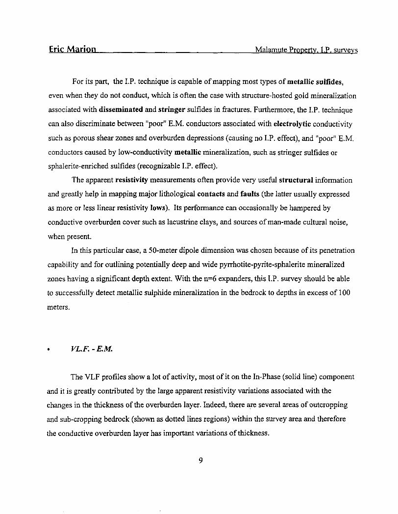
For its part, the I.P. technique is capable of mapping most types of metallic sulfides,
even when they do not conduct, which is often the case with structure-hosted gold mineralization
associated with disseminated and stringer sulfides in fractures. Furthermore, the I.P. technique
can also discriminate between "poor" E.M. conductors associated with electrolytic conductivity
such as porous shear zones and overburden depressions (causing no I.P. effect), and "poor" E.M.
conductors caused by low-conductivity metallic mineralization, such as stringer sulfides or sphalerite-enriched sulfides (recognizable I.P. effect).
The apparent resistivity measurements often provide very useful structural information
and greatly help in mapping major lithological contacts and faults (the latter usually expressed
as more or less linear resistivity lows). Its performance can occasionally be hampered by
conductive overburden cover such as lacustrine clays, and sources of man-made cultural noise,
when present.
In this particular case, a 50-meter dipole dimension was chosen because of its penetration
capability and for outlining potentially deep and wide pyrrhotite-pyrite-sphalerite mineralized
zones having a significant depth extent. With the n=6 expanders, this I.P. survey should be able
to successfully detect metallic sulphide mineralization in the bedrock to depths in excess of 100
meters.
VL.F.-E.M.
The VLF profiles show a lot of activity, most of it on the In-Phase (solid line) component
and it is greatly contributed by the large apparent resistivity variations associated with the
changes in the thickness of the overburden layer. Indeed, there are several areas of outcropping
and sub-cropping bedrock (shown as dotted lines regions) within the survey area and therefore
the conductive overburden layer has important variations of thickness.
Eric Marion__________________________Malamute Property. I.P. surveys
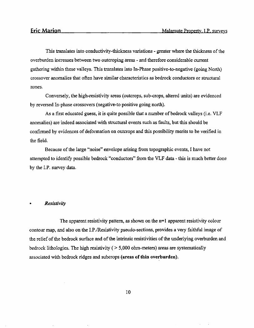
This translates into conductivity-thickness variations - greater where the thickness of the
overburden increases between two outcroping areas - and therefore considerable current
gathering within these valleys. This translates into In-Phase positive-to-negative (going North)
crossover anomalies that often have similar characteristics as bedrock conductors or structural
zones.
Conversely, the high-resistivity areas (outcrops, sub-crops, altered units) are evidenced by reversed In-phase crossovers (negative-to positive going north).
As a first educated guess, it is quite possible that a number of bedrock valleys (i.e. VLF
anomalies) are indeed associated with structural events such as faults, but this should be
confirmed by evidences of deformation on outcrops and this possibility merits to be verified in
the field.Because of the large "noise" envelope arising from topographic events, I have not
attempted to identify possible bedrock "conductors" from the VLF data - this is much better done
by the I.P. survey data.
* Resistivity
The apparent resistivity pattern, as shown on the n^ apparent resistivity colour contour map, and also on the I.P.7Resistivity pseudo-sections, provides a very faithful image of the relief of the bedrock surface and of the intrinsic resistivities of the underlying overburden and bedrock lithologies. The high resistivity (> 5,000 ohm-meters) areas are systematically associated with bedrock ridges and subcrops (areas of thin overburden).
10
Eric Marion—.^—.^———..———.—.^—.—.^——^——-Malamute Property. I.P. surveys
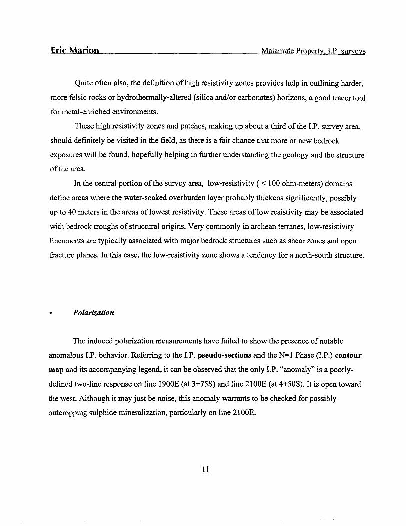
Quite often also, the definition of high resistivity zones provides help in outlining harder,
more felsic rocks or hydrothermally-altered (silica and/or carbonates) horizons, a good tracer tool
for metal-enriched environments.
These high resistivity zones and patches, making up about a third of the I.P. survey area,
should definitely be visited in the field, as there is a fair chance that more or new bedrock
exposures will be found, hopefully helping in further understanding the geology and the structure of the area.
In the central portion of the survey area, low-resistivity (< 100 ohm-meters) domains
define areas where the water-soaked overburden layer probably thickens significantly, possibly
up to 40 meters in the areas of lowest resistivity. These areas of low resistivity may be associated
with bedrock troughs of structural origins. Very commonly in archean terranes, low-resistivity
lineaments are typically associated with major bedrock structures such as shear zones and open
fracture planes. In this case, the low-resistivity zone shows a tendency for a north-south structure.
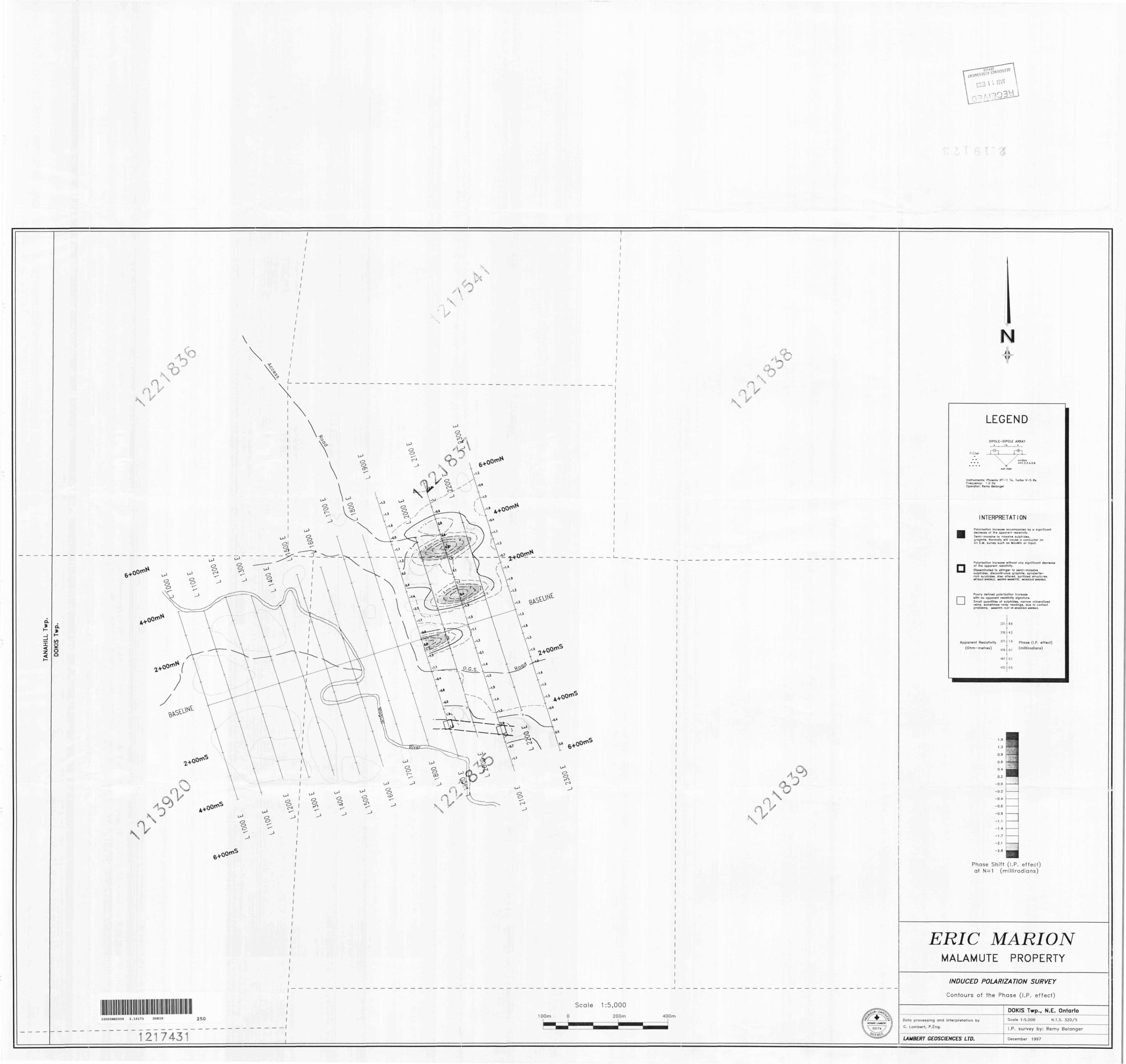
* Polarization
The induced polarization measurements have failed to show the presence of notable
anomalous I.P. behavior. Referring to the I.P. pseudo-sections and the N^ Phase (I.P.) contour
map and its accompanying legend, it can be observed that the only I.P. "anomaly" is a poorly-
defined two-line response on line 1900E (at 3+75S) and line 21 GOE (at 4+50S). It is open toward
the west. Although it may just be noise, this anomaly warrants to be checked for possibly
outcropping sulphide mineralization, particularly on line 21 GOE.
11
Eric Marion____________________________Malamute Property. I.P. surveys
Conductive, semi-massive and massive metallic mineralization (graphite and/or massive
sulfides) will typically cause a marked decrease in the measured apparent resistivity, in addition
to a strong I.P. anomaly. So will a mineralized shear corridor carrying disseminated or stringer
sulfides. No such responses were noted hi the I.P. data obtained.
Conclusion and recommendations
The V.L.F. - E.M. and Induced Polarization surveys which were recently completed on
the Malamute property for prospector Eric marion have defined several bedrock valleys of
possible structural origins, a large number of high-resistivity zones and only one trend
characterized by a slightly increased I.P. effect, hi the southeast of the grid.
It is difficult, from a geophysical point of view alone, to rate I.P. anomalies in terms of
their economic potential, especially if one is exploring the property for gold.
Recommending further work on this property, it is advisable to visit all the high
resistivity areas in search for potentially new bedrock exposures which will hopefully allow to
obtain some lithological samples and even possibly allow to explain the weak anomalous I.P.
response on line 21 GOE.
It is also strongly recommended to extend the I.P. survey coverage to the rest of the
property, as the I.P. method is a much more discriminating geophysical prospecting tool than the
VLF method.
Rouyn-Noranda, Quebec f Gerafd Lambert,
December 19, 1997 Consulting Geophysicist
12
a****.Declaration of Assessment Work Performed on Mining LandMining Act, Subsection 65(2) and 86(3), R.S.0. 1990
Transaction Number (office use)
W9S SO. 00033Assessment Files Research Imaging
f subsection 65(2) and 66(3) of the Mining Act. Under section 8 of the Mining Act, assesment work and correspond with the mining land holder. Questions about this
Northern Development and Mines, 3rd Floor, 933 Ramsey Lake Road, Sudbury,
32D05NE2008 2.19173 DOKIS 900
Instructions. - For work performed on Crown Lands before recording a claim, use form 0240. - Please type or print in ink.
1. Recorded holder(s) (Attach a list if necessary) 2.1 r/Name i
/^/9/C /?? rf/? 'S 'O *JAddress
pz\j iy*cName .
fjL.fl fsU C A-/Z/2& fi l4Address
// ^(^f^fAj s T , x^ .
Client N*tiber J^
Telephone Number7o^~~ ^~6 ?~1P7S~ fFax Number
Client Number
Telephone Number J O ^ " ^"~ C^D ~ c ^ C1 7"
Fax Number
2. Type of work performed: Check K) and report on only ONE of the following groups for this declaration.Geotechnical: prospecting, surveys,
X assays and work under section 18 (regs)Physical: drilling stripping, trenching and associated assays
Rehabilitation
Work Typeo/^/D ,
Oates Work From Performed Cs \
i"-^ x y/i /L /QfSA^/Q
Day | Month 0 j
Global Positioning System Data (if available)
r__________ L-
To | Year tf ~f- DayC/ | MonthCjJ Year (^ g
Township/Area K . J 1^^ ff fi fLi^ t ktfy^K
MorG-PlanNumber 7X0
Office UseCommodityTotal S Value of Work Claimed 1 8 795NTS Reference
Mining Division l^^ rc[^ l o.k^Resident Geologist . District 'KiV^'/CL^L^ Kj3-A4—.
Please remember to: - obtain a work permit from the Ministry of Natural Resources as required;- provide proper notice to surface rights holders before starting work;- complete and attach a Statement of Costs, form 0212;- provide a map showing contiguous mining lands that are linked for assigning work;- include two copies of your technical report.
3. Person or companies who prepared the technical report (Attach a list if necessary)Name
6 ae /w? ̂ LPrmfi&J* TAddress
/^f Cf~0^(f^ "S T. &6UVAJ , QLsf-AGCName '
rS/^ / d^ /TO /V2 ' c? A/Address
Name
Address
D CT /^ r" i \ y r"MbULI VI
JAN 1 1 -::3 •3~^(h i*GEOSCIENCFASSES3W
Telephone Number di 1 Ci — '3 f, Q ^- ? J C O
Fax Number^/*7 - 743
Telephone Number-\ 1 S 6 7 t?'
LPaxjNumber
Teleiphone Numberr i
l^ax Number
- S 3 4 f
?r/
Certification by Recorded Holder or Agentl. , do hereby certify that l have personal knowledge of the facts set forth in
(Print Name)
this Declaration of Assessment Work having caused the work to be performed or witnessed the same during or after its completion and, to the best of my knowledge, the annexed report is true.Signature of Recorded Hglder or Agent .
Agent's Addresssiutf. X^
Telephone Number ~?C^~ ^~(?'9~ ~3~?'*~ S
Date
Fax Number
0241 (03/97)
II
IU UUaccompany!
-- , do hereby certify (hat the above work credits are efigftfesubsection 7 (1) of DM Assessment Work Regulation 6/96 for assignment to contiguous cWms or for application to the da where lh* mnrfr un* ,*~—where Hw work was done.
Instruction for cutting tack credits that are not approved.
Some of the credits claimed in this declaration may be cut back. Please check (-0 in the boxes below lo show how you w! prioritize the deteUon of credits:
D 1. Credits are lo be cut back from Irm Bank first. Mowed by option 2 or 3 or 4 as indicated.Q 2. Credits are to be cut back starting with the claims fisted last, working backwards: orQ 3. Credits are lo be cut back equally over afl claims feted in this declaration; orQ 4. Credits are lo be cut back as prioritized on Hie attached appendix or as foHows (describe):
Note: If you have not indicated how your credits are to be deleted, credits wil be cut back Cram the Bank first, fotowed by option number 2 if necessary.
04110*171
RECEIVEDLARDER LAKE
MINING DIVISION
RECEIVES
GEOSCIENCE ASSESSMENT JFFjCE
** TOTflL
Received Stamp
0241 (03/97)
RECEIVED LARDER LAKE MNG DIVISION
-JAN 8 \
Deemed Approved Date
Date Approved
uate Noimcauon
Total Value of Credit Approved
Approved for Recording by Mining Recorder (Signature)
RECEIVED\l.!AN
GEOSCIEhiCF ''SSESSMENT______ QfUCE _______
Statement of Costs for Assessment Credit
Transaction Number (office use)
Personal Information collected on this form Is obtained under the authority of aubMctton 6 (1) of the Ataaaament Work RegtrlaUon 6/90. Under section S of the Mining Art. this Information la a pubHc record. Thto Information wH be used to review Hw assessment work and correspond wRh the mining land hokter. Questions about this collection should be directed to a Provincial Mining Recorder. Ministry of Northern Development and Mines. 3rd Floor. 933 Ramsey Lake Road, Sudbury. Ontario, P3E 6B5.
Work Type
L )i\i F CLlTTHJic
li Sis&ufcyitcnvicAi. ^fc^/^r
/3^x?ySLj-iF ^u#uK.y
vC/SSS^I*'* *a!iSSr ^'^^r- f f •***'l j -*y ifitf'tH
Jl t R (s. O ///^P*
Units of workDepending on the type of work, 1st the number of hours/day worked, metres of drilling, kilometres of grid line, number of samples, etc.
14 Krt\ ^^^iL'^tJrrwkjl.**~XtY\ \***1 A*.*"***}
i d^e^ft 4/^/J^r i
^ ~ 5" w-1 fl^ttfr LfUl
14- km3o P/?/^ \f^*A) Nj
3 o fafw ^/9V^Associated Costs (e.g. supplies, mobilization and demobilization).
O 1————— fc 9 JiTransportation Costs
2 S V /S6 /r - T? Se /c
Food and Lodging Costs
jtf O JLu/v f H fc^/t?
Cost Per Unit of work
lee cc/^m- —.. _ .cX6,ec)
/^.^//f/v?l5U.cc} /^/iy/so.ec/p/ty
9 1 7 -3 —
^?c.^)^
Total Value of Assessment Work
Total Cost
43CQ d G
3140.00
Jfj IL .fOf53.^C
/7SO -00
loco od
i/ 3 S 06
r ^g^ tfO
/B,7f^n
Calculations of Filing Discounts:
i Work filed within two years of performance is claimed at 100^0 of the above Total Value of Assessment Work. 1 If work is filed after two years and up to five years after performance, it can only be claimed at 50"Xo of Hie Tolal
Value of Assessment Work If this situation applies to your claims, use the calculation below:
IOTAL VALUE OF ASSESSMHNI WORK x 0.50 = Total S value of worked claimed
iote:Work older than 5 years is not eligible for credit.A recorded holder may be required to verify expenditures claimed in this statement of costs within 45 days of a request for
erification and/or correction/clnrificalion. If verification and/or correction/clarification is not made, the Minister may reject all T part of the assessment work submitted.
'ertificatlon verifying costs:
__, do hereby certify, that the amounts shown are as accuiate as may reasonably(please print full name)
determined and the costs were incurred white conducting assessment work on the lands indicated on the accompanying
)eclaration of Work form as f. ('6/0 fr/^fe /-I&."d holder, agent. 01 stale company position with signing authority)
l am authorized to make this certification
?12 (03(97)
RECEIVED LADDER LAKE
iN 8\V* JAN j i ;:ri
GEOSCIt'NCr ^;-SciiS OFFlCF
Ministry of^\ , t Minisiry 01C jntflriO Northern DevelopmentVXI IU4I t\S .-H iilnoeand Mines
Declaration of Assessment Work Performed on Mining LandMining Act, Subsection M(2) and M(3), R.8.0.1*90
Transaction Number (office use)
Assessment Files Imaging
Personal Information collected on this form Is obtained under the authority of subsections 65(2) and 66(3) of the Mining Act. Under section 8 of the Mining Act, the Information is a public record. This information will be used to review the assessment work and correspond with the mining land holder. Questions about this collection should be directed to the Chief Mining Recorder, Ministry of Northern Development and Mines, 6th Floor, 933 Ramsey Lake Road, Sudbury, Ontario, P3E 6B5.
Instructions: - For work performed on Crown Lands before recording a claim, use form 0240. - Please type or print in ink.
1. Recorded holder(s) (Attach a list if necessary) li r/Name Client Number
f l* (.14-Telephone NumberAddress
Fax Number
Name
Address
.—JLL
Client Number
Telephone
Fax Number
2. Type of work performed: Check ( s ) and report on only ONE of the following groups for this declaration.
D Geotechnical: prospecting, surveys, assays and work under section 18 (regs)
Physical: drilling, stripping, trenching and associated assays Rehabilitation
Work Type •St/^/P*/^'^ i- TT- T~G- f*7*~s (^ r/'/fJ b
Perf r̂k F™ 03L /b .77- To /U /O 97-Day Month | Year bay Month Year
Global Positioning System Data (if available) Township/Area
M or G-Plan Number
ffi- 343'
Office UseCommodity
Total $ Value of Work Claimed &I (t 0
NTS Reference
Mining Division ^ , L^k.
Resident Geologist District Kttkl^^ LL^C^
Please remember to: - obtain a work permit from the Ministry of Natural Resources as required;- provide proper notice to surface rights holders before starting work;- complete and attach a Statement of Costs, form 0212;- provide a map showing contiguous mining lands that are linked for assigning work;- include two copies of your technical report.
3. Person or companies who prepared the technical report (Attach a list if necessary)Name
f^ic, /tt/fee/otJAddress fr
i 2 Lo fouA)(ft*J A-ijF K IJ?tiA*jr^ L AkifName
Address
Name
Address
DCT/*** CI \ 'f" rNncv/ei v tU
JAN i i :::j/O&JQ/J
BhOSCIEhCE ASSESSMENT OfFlCF
Telephone Number
9tf-r-^~d9-^7r/Fax Number
Telephone Number
:ax Number
Telephone Number
Fax Number
4. Certification by Recorded Holder or Agent
i, f^/Q'C /n_______________ , do hereby certify that l have personal knowledge of the facts set(Print Name)
forth in this Declaration of Assessment Work having caused the work to be performed or witnessed the same during or after its completion and, to the best of my knowledge, the annexed report is true.
Signature of Recorded
Agent's Address
;2L P?"
Holder or Agent
-. **s~ ———— ̂
K. L,Telephone Number
Date ,
Fax Number
5. Work to be recorded and distributed.the mining land where work was performed, must accompany this form.
Work can only be assigned to claims that are contiguous (adjoining) to at the time work was performed. A map showing the contiguous-link
Mining Claim Number. Or if work was done on other eligible mining land, show in this column the location number indicated on the claim map.
eg
eg
eg
1
2
3
4
5
6
7
8
g
10
11
12
13
14
15
TB 7827
1234567
1234566
i^a/flS 9-
/aa/fcsS
Number of Claim Unite. For other mining land, list hectares.
16 ha
12
2
LIt
Column Totals
Value ol work performed on this claim or other mining land.
126, 825
0
$ 8, 892
^1 Ln.OO-*~~
r-V, - Q
rO o JL Z?
5 i (tC.OG
Value of work applied to this claim.
N/A
$24,000
S 4,000
a A oo at*5 7 40.40
.r, J- f f
1 i o
S/60.00
Value of work assigned to other mining claims.
S24,000
0
0
2-96tf.CO
2?4o0o
Bank. Value of work to be distributed at a future date.
12,825
0
14,892
——
__ —
, do hereby certify that the above work credits are eligible under(Print Full Name)
subsection 7 (1) of the Assessment Work Regulation 6/96 for assignment to contiguous claims or for application to the claim where the work was done.Signature of Recorded Holder orir Agent Authorized in Writing
X*XV-X-^- - — -.__.
Dale
6. Instructions for cutting back credits that are not approved.
Some of the credits claimed in this declaration may be cut back. Please check ( ^ ) in the boxes below to show how you wish to prioritize the deletion of credits:
D 1. Credits are to be cut back from the Bank first, followed by option 2 or 3 or 4 as indicated.D 2. Credits are to be cut back starting with the claims listed last, working backwards; orD 3. Credits are to be cut back eqi D 4. Credits are to be cut back as Hi
in this declaration; or appendix or as follows (describe):
JAI; ' \
GEOSCIENCf iSSOfFlCt
Note: If you have not indicated how your credits are to be deleted, credits will be cut back from the Bank first, followed by option number 2 if necessary.
For Office Use Only________________Received Stamp Deemed Approved Date
0241 (02/961
LARCEfi LAK ~ MINiNK DIViG'Oi-J
"JAN 8
11 - M CT r, x~.
Date Approved
Date Notification Sent
Total Value of Credit Approved
Approved for Recording by Mining Recorder (Signature)
J***** ^northern Developmentand Mines
Statement of Costs. . . . - J11for Assessment Cred t
Transaction Number (office use)
Personal Information collected on this form Is obtained under the authority of subsection 8(1) of the Assessment Work Regulation 6/96. Under section 8 of the MWng Act. this Information to a public record. Thto Information wW be used to review the MMSsmenl work ami correspond wtth the mlnlr^ lend holder. Questions about this collection should be directed to a Provincial Mining Recorder, Ministry of Northern Development and Mines, 3rd Floor, 933 Ramsey Lake Road. Sudbury, Ontario. P3E 6B5
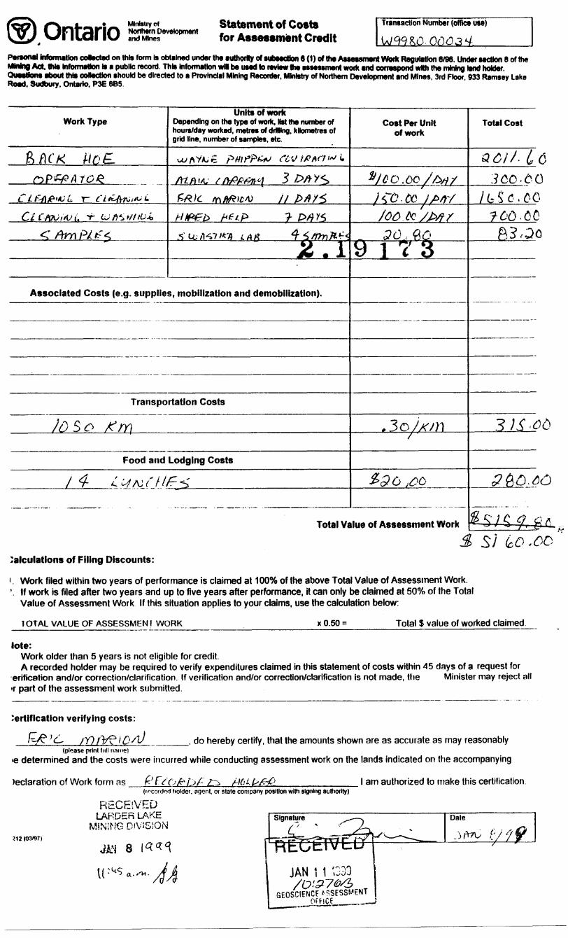
Work Type
fcftcx tioE-nPf&ATOQ
CLPAML r- CL*AK,*LCtC-MVt. -r Utei/ltU*
< /frn PA fcr^
Units of workDepending on the type of work. Hst the number of hours/day worked, metres of drilling, kilometres of grid line, number of samples, etc.
uyflV/Uo pHlPr't-^J fC'J ItffifTi*1 i
/TC/J-/L-' //WPA^/ 3 OAY^
fZ&it K\ftfZw\) II frfiY1̂
Hlf&b he*.F* J- ps)Y5fiu/K?'** LAK 4^mnK^2.1
'
Associated Costs (e.g. supplies, mobilization and demobilization).
Transportation Costs
Id B o fjr\
Food and Lodging Costs
l d- ' ' A ' i- IE- '
Cost Per Unit of work
fyco.dc//M//CO.cc iP/ty/0& te /P/}/30 . fiO
9173
.3oSx;n'
Q ''9 '6 iOC*
Total Value of Assessment Work
Total Cost
O x^ f J 1 ASO//- (f C
3CQ.6Q/G^'C.CC
7^0.00ft?,Qo
3)S'Qb
3&&.6O
^SK-4l-gAJ
Calculations of Filing Discounts:
i. Work filed within two years of performance is claimed at 1000Xo of the above Total Value of Assessment Work. '. If work is filed after two years and up to five years after performance, it can only be claimed at 50"Xo of the Total
Value of Assessment Work If this situation applies to your claims, use the calculation below:
1OTAL VALUE OF ASSESSMEN? WORK K 0.50 s Total S value of worked claimed.
lote:Work older than 5 years is not eligible for credit.A recorded holder may be required to verify expenditures claimed in this statement of costs within 45 days of a request for
erification and/or correction/clarification. If verification and/or correction/clarification is not made, the Minister may reject all T part of the assessment work submitted.
Certification verifying costs:
____, do hereby certify, that the amounts shown are as accurate as may reasonably(please print full name)
determined and the costs were incurred while conducting assessment work on the lands indicated on the accompanying
)eclaration of Work form as fc t t t-IU. l am authorized to make this certification.ted holder, agenl, or slate company position with signing authority)
m (03/97)
RECEIVEDLARDER LAKE
MiNiNG DIVSSSON
JAN 8 14^
JAN l 1 ',GEOSCIENCF ASSESSMENT
, —— f
Ministry ofNorthern Developmentand Mines
March 10, 1999
ERIC JOSEPH MARION 126 DUNCAN AVENUE KIRKLAND LAKE, ONTARIO P2N-1Y5
Ministers du Developpement du Nord et des Mines Ontario
Geoscience Assessment Office 933 Ramsey Lake Road 6th Floor Sudbury, Ontario P3E 6B5
Telephone: (888)415-9846 Fax: (877)670-1555
Visit our website at: www.gov.on.ca/MNDM/MINES/LANDS/mlsmnpge.htm
Dear Sir or Madam:
Subject: Transaction Number(s):
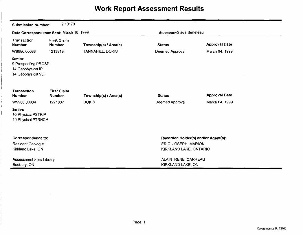
Submission Number: 2.19173
StatusW9980.00033 Deemed Approval W9980.00034 Deemed Approval
We have reviewed your Assessment Work submission with the above noted Transaction Number(s). The attached summary page(s) indicate the results of the review. WE RECOMMEND YOU READ THIS SUMMARY FOR THE DETAILS PERTAINING TO YOUR ASSESSMENT WORK.
If the status for a transaction is a 45 Day Notice, the summary will outline the reasons for the notice, and any steps you can take to remedy deficiencies. The 90-day deemed approval provision, subsection 6(7) of the Assessment Work Regulation, will no longer be in effect for assessment work which has received a 45 Day Notice. Allowable changes to your credit distribution can be made by contacting the Geoscience Assessment Office within this 45 Day period, otherwise assessment credit will be cut back and distributed as outlined in Section #6 of the Declaration of Assessment work form.
Please note any revisions must be submitted in DUPLICATE to the Geoscience Assessment Office, by the response date on the summary.
If you have any questions regarding this correspondence, please contact Steve Beneteau by e-mail at [email protected] or by telephone at (705) 670-5855.
Yours sincerely,
ORIGINAL SIGNED BYBlair KiteSupervisor, Geoscience Assessment OfficeMining Lands Section
Correspondence ID: 13465
Copy far: Assessment Library
Work Report Assessment Results
Submission Number: 2.19173
Date Correspondence Sent: March 10, 1999 Assessor: Steve Beneteau
Transaction NumberW9980.00033
Section:9 Prospecting PROSP 14 Geophysical IP 14 Geophysical VLF
First Claim Number1213918
Township(s) l Area(s) TANNAHILL, DOKIS
StatusDeemed Approval
Approval Date
March 04, 1999
Transaction NumberW9980.00034
Section:10 Physical PSTRIP 10 Physical PTRNCH
First Claim Number1221837
Township(s) l Area(s) DOKIS
StatusDeemed Approval
Approval Date
March 04, 1999
Correspondence to:Resident Geologist Kirkland Lake, ON
Assessment Files Library Sudbury, ON
Recorded Holder(s) and/or Agent(s):ERIC JOSEPH MARION KIRKLAND LAKE, ONTARIO
ALAIN RENE CARREAU KIRKLAND LAKE, ON
Page: 1Correspondence ID: 13465
REFERENCESAREAS WITHDRAWN FROM DISPOSITION
M.R.O. - MINING RIGHTS ONLY
S.R.O. - SURFACE RIGHTS ONLY
M.+ S. - MINING AND SURFACE RIGHTS
DMcription Order No. D*M Disposition Pile
NOTICE OF FORESTRY ACTIVITY THIS TOWNSHIP l AREA FALLS WITHIN THE ABITIBI MANAGEMENT UNIT AND MAY BE SUBJECT TO FORESTRY OPERATIONS THE MNR UNIT FORESTER FOR THIS AREA CAN BE CONTACTED AT;
P.O. BOX 129SWASTIKA, ONTARIOP OK IT O 705-642-3222
THE INFORMATION THAT APPEARS ON THIS MAP HAS BEEN COMPILED FROM VARIOUS SOURCES. AND ACCURACY IS NOT GUARANTEED THOSE WISHING TO STAKE MIN ING CLAIMS SHOULD CON- SULT WITH THE MINING RECORDER. MINISTRY OF NORTHERN DEVELOP MENT AND MINES. FOR AD DITIONAL INFORMATION ON THE STATUS OF THE LANDS SHOWN HEREON.
XCO
o I-
H O-l-JUJ
HOLLOWAY TOWNSHIP
I7M.
I6M.
1202594 5i , 1221822
h -———L.
1221701122182
1221829———T- —————————
221834i -
53Z5 l 9353291— ~n93^330. l —— ,
1221688 I222330
i ———4.—-rI2II9I9 1211523 213918i 1220246
"tosMCcii ~~ '"s l
-——' 1217429l 1213843u --.--— ,.
1213861213899
I2O256I
1221803
BEN NEVIS TOWNSHIP ARCHIVED JULY 28, 1995 ARCHIVED FEB. 10/97
l
LEGENDHIGHWAY AND ROUTE No. OTHER ROADS TRAILS SURVEYED LINES:
TOWNSHIPS. BASE LINES, ETC.LOTS. MINING CLAIMS, PARCELS, ETC
UNSURVEYED LINES:LOT LINESPARCEL BOUNDARYMINING CLAIMS fTC
R A! LWAY AND RIGHT OF WAY UTILITY LINES NON-PERENNIAL STREAM FLOODING OR FLOODING RIGHTS SUBDIVISION OR COMPOSITE PLAN RESERVATIONS ORIGINALSHOREDNE MARSH OR MUSKEG MINES TRAVERSE MONUMENT
DISPOSITION OF CROWN LANDS
TYPE OF DOCUMENT SYMBOLPATENT, SURFACE ft MINING RIGHTS ..^.............. *
.SURFACE RIGHTS ONLY........ ........ ...,^ 9
.MINING RIGHTS ONLY___........ ......._. OLEASE, SURFACE 8t MINING RIGHTS---,.^,........... B
" .SURFACE RIGHTS ONLY^.,.^ ...........^^. H" .MINING RIGHTS ONLY....,....................... y
LICENCE OF OCCUPATION .._....—................... TORDER-IN-COUNCIL ......-,—,^..—...............,... OCRESERVATION ___........— .........^........^..,... ©CANCELLED ___......._——.—.................. ®SAND 8. GRAVEL ._......._...........................
SCALE: 1 INCH - 40 CHAINS
FEET1000 20OO 4OOO 6OOO 8000
O 200 METRES
1000(l KM)
2OOO (2 KM)
TOWNSHIP
DATE OF ISSUE
APR O 11999PROVINCIAL RECORDING
OFFICE-SUDBURY
TANNAHILLM.N.R ADMINISTRATIVE DISTRICT
KIRKLAND LAKEMINING DIVISION
LARDER LAKELAND TITLES/ REGISTRY DIVISION
COCHRANE
Ministry ofNaturalResources
Ministry ofNorthern Developmentand Mines
Ontario
DateAPRIL 1990
UHCULATED FEBRUARY l, 1995
Number
G-3717
CD i
~D
CD i
OJ
32D05NE2008 2.19173 DOKIS 200
r
.1
k)Wft-u&aM
01
O)
Oo
MARRiOTT TWP. M 363
4 M
O
^ y 1 7 M
J22I700
1221701
GO (M 12^1838
1221837•t PTRNCH
CL.
h-
LjX
2*
i ,,
3V
2M
^^N^vA,̂ \
0
"^ ro
^*i
ro
j
r
1221835
.
IV
CO
32D05NE2008 2.19173 DOKIS 210
ICM nw
O -
J
v;;. v. ;vv:JATE RECEIVED JAN 24/39
n
•60W
- 59 v.
58M
LiJ CD Lkl
O
uC)tar v
orr.
THE INFORMATION THAT APPEARS ON THIS MAP H-AS BEEN COMPILED FROM VARIOUS SOURCES. AND ACCURACY IS NOT GUARANTEED THOSE WISHING TO STAKE MIN ING CLAIMS SHOULD CON SULT WITH THE MINING RECORDER. MINISTRY OF NORTHERN DEVELOP MENT AND MINES. FOR AD DtTIONAL INFORMATION ON THE STATUS OF THE LANDS SHOWN HEREON
79 : Ji'04"
COPY OF TUS MYLAR ARCHVEO SEPT 27, 1991ARCHIVED AUGUST 24, 1994
ARCHIVED JUNE 5/97
Di
400 SO .''a! : r,;., 1 '
DATE OF (SSUE
0 f 7999
NOTICE OF FORESTRY ACTIVITYTHIS TOWNSHIP ; AREA FALLS WIHIN THE __
AND MAY BE SUBJECT TO FORESTRY OPERATONS, THE MNR UNIT FORESTER FOR THIS AREA CAN BE CONTACTED AT :
i C f~* C ^ iL r. v.11- , , L
PAT? M t f 1 L"' (3;:'V*
r f
GF- . L or : •"J '. AN r
-"'J
-\: \
s. i f x /:JUNE 10, 1988
MINISTRY OF NORTHERN DEVELOPMENT
AND MINES @@
W
k)
o o
Y
I iN3iNSS3SSvlON310SQ3S
G661 l l NVf
T ,f~i ~r o^ 6 I
32D05HB2008 2.19173 DOKIS
Scale 1:5,000
100m O 200m 400m
1217431
AIr
or
2 b
4 C
— — — — Claire
ttt frail and
- A/euJy
Vx
MARIONMALAMUTE PROPERTY
Data processing and interpretation by G. Lambert, P,Eng.
LAMBERT GEOSCIENCES LTD.
DOKIS Twp.. N.E. OntarioScale 1:5,000 N.T.S. 32D/5
December 1997
^
32D05NE200S 2.19173 DOKIS 230
1217431
100m
Scale 1:5,000
O 200m 400m
LEGEND
Pro f Ho scale: Icm^SOZ
Instrument: Geontcs EM—16
Station: NAA, Cutler, Maine
MARIONMALAMUTE PROPERTY
Profile scale:
.Lf. - F.A/. SurveyProfiles of the In —Phase and Quadrature components
Station: NAA, Cutler, Maine
Data processing and interpretation by G. Lambed, P.Eng,
LAMBERT GEOSCIENCES LTD.
DOKIS Twp., N.E. OntarioScale 1:5.000 N.T.S. 32D/5
VLF survey by: Eric Morton
December 1997
iN3WSS3SS* JON3I3S039
665111 t;vr
S ,l T 6 T ' 3?
LEGEND
Instruments: Phoenix IPT-1 Tx, Turbo V-5 Rx Frequency: 1.0 Hz Oparator: Remy Belanger
lNTERPRETATl ON
Polarisation Increase accompanied by a significant decrease of the apparent resistivity.Semi—massive to massive sulphides, graphite. Normally will cause a conductor on on E.M. survey such as MaxMln or Input.
Polarisation increase without any significant decrease of th* apparent resistivity.Disseminated to cirtngtr to seml-masslva sulphides, discontinuous graphite, (pholerite— rich sulphides. Also altered, pyritizad structures.META1JJC NINEHAL5. MA5SIVC MACHETHE. yiCACEOUS MINERALS.
Poorly defined polarisation increasewith no apparent resistivity signature.Small quantities of sulphides, narrow mineralizedveins, sometimes noisy readings, due to contactproblems. MAGNETITE. CLAY on MICACEOUS UIMERALS.
16 Phase (I.R. effect) Q , (mflliradians)
Apparent Resistivity (Ohm-metres)
Apparent Resistivity at N^1 (Ohm-meters)
ERIC MARIONMALAMUTE PROPERTY
INDUCED POLARIZATION SURVEY
Contours of the apparent resistivity
Scale 1:5,000
O 200mDOKIS Twp.. N.E. Ontario
Data processing and interpretation by N.T.S. 32D/532D05NE2006 2.19173 DOKIS
G. Lambert, P.Eng.
LAMBERT GEOSCIENCES LTD.
.P. survey by: Remy Belanger
\
l/
^
l
LEGEND
DIPOLE-DIPOLE ARRAY
Filter
BPIDI roiifr
Instruments: PhoeniK IPT-1 Tx, Turbo V-5 Rx Frequency: 1.0 Hz Operator: Remy Belanger
lNTERPRETATl ON
Apparent Resistivity i77
(Ohm-metres) ,. HPhase (I.R. effect)
(mllliradlans)
Polarisation increase accompanied by a significant decrease of the apparent resistivity. Sami—massive to massive sulphides, graphite. Normally will causa a conductor on an E.M. survey such as MaxMln or Input.
Polarisation increase without any significant decrease of the apparent resistivity.Disseminated to slrlnger to semi-massive sulphides, discontinuous graphite, sphalerite- rich sulphides. Also altered, pyritized structure*.UETALLJC MINERALS. UASSIVt MAGNETITE. MICACEOUS MINERALS,
Poorly defined polarisation increasewith na apparent resistivity signature.Small quantities of sulphides, narrow mineralizedveins, sometimes noisy readings, due to contactproblems. MAGMFITTE, CLAY ait MICACEOUS MINERALS.
32D05NE2008 2.19173 DOKIS 250
Scale 1 :5,000
100m O 200m 400m
1.9
1.3
0.9
0.6
0.4
0.2
-0,0
-0.2
-0,4
-0.6
-0.9
-1.1
-1.4
-1.7
-2.1
-2.8
Phase Shift (l.P. effect) at N —1 (milliradians)
ERIC MARIONMALAMUTE PROPERTY
INDUCED POLARIZATION SURVEY
Contours of the Phase (I.R. effect)
Data processing and interpretation by
G. Lambert, P.Eng.
LAMBERT GEOSCIENCES LTD.
DOKIS Twp., N.E. OntarioScale 1:5,000 N.T.S. 32D/5
l.P. survey by: Remy Belanger
December 1997
ROO POO 2137 .55.
J
1069 J .28.
RESISTIVITY OHM-METERS
PHASE
M RAO
oJ OJ
______7
POO ROO ..55 2137
L..28 L1069
lL l
.o Lo
2+00 1+00 S o+oo 1+00 N4+00 S | | 3+00 S|
Filter '57 195 243 306 157 337 410 1943 661 815 687 597
2+00 N 3+00 N 4+00 N 5+00 N418 301 291 244 193 170 Filter
100 138-——329 ;v's 8944 s;, 419 __ 334 , 149 x 386 v 168 ~-_110 i 87V'
911341 222 \ 464 , 85S
/ / 93, (268
763//, 77 -y/W \ 873 ^ 1648 , 829 \l i//// l (l l \\X \ \ ^^' f i 94 /m 352 \ 732 \ 1655 — 1;(^(^^j;)/^:
79 73 79____SO 84 0=1
0=2
489 374 \ 213——" 229 258 ~"~~ 197 ^ 165 0 = 3
'829lS^229 \ 492 __ 452 "319^ 349 358 "\ 236 0=4
0=5
'2292'- v NXX "263 "~~~~ "^ 896""———— 479 0 = 6
1299 \\234 -i 560 644 ^-- 461 444 404
4+00
Filter
3+00 S 2+00 1+00 : 0+00 1+00 N 2+00 N 3+00 N 4-+00 N 5+00 N
-.70 -.60 -.40 -.95 -1.2 .60 -1,1 -1.6 -1.4 -1 -1.2 -1.7 -1.8 -1.7 -1.8 -1.6 -1.5 Filter
0=1 1.5 s 1.4 ,- -.50 -m -.40 -1.1 -1.5 ^6.8 '/f -.60 -1.1 -2.1 -1.4 .40 .20 -1.2 -1.1 -.90 -1.6 -1.3 -1.2 0=1
0 = 2 1.6 , 1.3 f -1.7 -1.2 -.40 -.90 -1.3 -1.2*^ .70 -1 -1.4 -1.2 -1.2 .30 -1.7 -1.3 -1.5 -2.2 -1.2 -1.3 0 = 2
0 = 3 .90^ -2.1 -1.6 -.70 -.50 -1.1 -1.2 -1.1 ^...50 -1.3 -1.1 -1.9 -1.1 -1.2 -1.9 -2.2 -2.1 -1.4 -1.9 0 = 3
0 = 4 -2.1 -1.7 ^rr^-j .10 -.90 -1.3 -1.1 .60 -2 -1.1 -1.1 -2.1 -1,9 -2.I -ZJ -2.1 -2.2 -1.9 0 = 4 j?"s~\\\^-^
0 = 5 -2.1 ^2.1 ,/ 70 ^ .50 -1.9 -1.2 -1.9 -2 -1.1 -.60 -1.7 -1.3 -2 -1.9 -1.2 -2.2 -2.1 0 = 5
0 = 6 1.2 l S~~ -l -1.2 -1.2 -1.4 -2.1 -2 -12 0 = 6
RESISTIVITY OHM-METERS
PHASE M RAO
Line 1900 EDipole-Dipole Array
na
Filter*
* * * * *
* * *
r±La = 50.0 M
plot point
Logarithmic Contours 1, 1.5, 2, 3, 5, 7.5, 10,...
INTERPRETATION
Strong increase in polarization accompanied by marked decrease in resistivity.
Well defined increase in polarization without marked resistivity decrease.
Poorly defined polarization increase with no resistivity signature.
Low resistivity feature.
Scale 1:500050 100 150
(metres)
ERIC WRON
INDUCED POLARIZATION SURVEY MALAMUTE PROPERTY DOKIS TWP. ONT/TO
Date: 97/08/27 Interpretation: GERARD LAMBERT ( V-5 PHOENIX RX
REMf BELANGER (GEDPHfS&L COWMC7VR)Geosoft Software for the Earth Sciences
32D05NE2008 2.19173 DOKIS 260
ROO POO4374 1.2,
J2187J .61.
RESISTIVITY OHM-METERS
PHASE MRAD
oJ OJ
i——rPOO ROO
r 1.2 4374
Ll
-61 1.2187 l l
.0 Lo
&+OQS 34-00 2+00 S 1+00 S 0+00 14-00 M 2+00 H 3+00 N 4+00 N 5+00 N
Filter 293 348 410 567 437 403 330 282 319 376 473 695 843 3BB7 2275 2837 J181 3976 1037 727 569
11 v- 293 x 4S7 , 713 —— 620 3291— 14Z ~^ 104 109 S
1662 = 19B5' -"762 535 . 321 —- 270 \ 135
341 vU 4654 ^ 3645 4998 1335 1127 J\ 446
, 9 O 560
1599
Filter
r^1
^=2
n-3
0 = 4
0=5
5+00 S 4+00 S 3+00 S 2+00 S 1+00 S 0+00 1+00 N 2+00 N 3+00 H 4+00 N 5+00 N
Filter
[1=1
[1=2
11=3
[1=4
11=5
[1=6
-1.1 -.40 50
-t.l -.70
-12-1.2
-.50
.80 -.10 -.70 -1.2 -1.3 -1.5 -1.5 -1.3 -1,2 -.90 -.60 1.
1.4 v^ -1.2 -1.4 -t.5 -1.2 -1.4 -2.1 -1.3 -1.1 -I.S
t.S \\^ -.90 -12 -I.B -1.5 -1.3 -1.6 -1.1 -'.B
-.90 -1.5 -1.7 -1.6 -1,6 -1.7 -1.3 -1.5 VJ.1 y -1.2 -.60 ^1,1 i 2.2 ^T -\A -'-t ^' 1-2.^ -t-2
-1.4 -1.7 -.90 -I.2 -1.3 -.40 ' i] I.4/T -1.3 -1.1 -1^ '^1.5 i.i
-1 -1.8 ^ 1.2
-1.2 .10 ~" .40 -.90 -1.1 -1.1
-.90 20 ^ .60 \ 1.3 XN, -1 -1.7 -l\\ \\\
-.90 ' .80 .50 rv 1.1 \ -1.2 -1.4
.20 .50 .TO 1.1 -JO .60 -.10 -.fi)
.40- -1.2 -2.2
-1.9 -2.1 -.70 .90 ^^ IJ ;\ -1.1 -.30 ^{J^-^
-1.J Filter
-12 11=1
^1=3
^=4
11=5
[1=6
RESISTIVITY OHM-METERS
PHASE
MRAD
Line 2100 EDipole-Dipole Array
no
Filter
s x\ x
plot point
o = 50.0 M
Logarithmic Contours l, 1.5, 2, 3. 5, 7.5, 10,...
INTERPRETATION
D
50___O
Strong increase in polarization accompanied by marked decrease in resistivity.
Well defined increase in polarization without marked resistivity decrease.
Poorly defined polarization increase with no resistivity signature.
Low resistivity feature.
Scale 1:500050 100 150 200 250
(metres)
ERIC
INDUCED POLAREMION SURVEY M/QUWUTE PROPERTY DOKIS TWP. ONTARD
Date: 97/08/27 Interpretation: GERARD LAMBERT ( V-5 PHOENIX RX )
REMf BELANGER (GE&W&C&Geosoft Software for the Earth Sciences
DOKIS270
RESISTIVITY OHM-METERS
PHASE M PAD
ROO POO 644 .22.
J
l
322j .11J
oJ oJ
\\
POO ROO ,-.22 644
L
-.11 [322 l L
.0 Lo
5+OOS 4+OOS 3+00 S 2+00 S 1+00 0+00 1400 N 2+00 N 3+00 N 4+00 N 5+OON
Filter 269 264 253 244 231 207 179 168
[1 = 1 tat . 37 K ^ 3.1 ——— 92 ——— 93 — 98 ^^ 67
[1=2 179 ^^JW--^. 132___J 43 —— 143 —— 140 122
[•1=3 302 -—^^S"^~*-- IBS 191 ___ 187 158 ~—— 151
0=4 446 362 ""-vJje 235 200 ^
0=5 618^ 461 286 249 231\ Tfln
53
169 177 191 233 270 371 424 477 4B6 493 585 468 569 464 294 niter
14! 235 i 196 - 391 v 18677 73 —— 78 - 1U
117 120 ^~106 ——— (17.^^1S3~~"-v. 142
^=6 745
——Sil —— 514 1B3
2IO 236 280 524
215 236 , 308, 247 268 ^-316 529 X 449 / 563
292 v MO " 353 ' 792 ———— 1274
54 ^ 662 852 l i 207 •
- ;
433 __ 384 758 \ 324
S 849 \ 461'
38e wt W 210 0=4
[1=5
5+00 S 4+OOS 3+00 S 2+00 S 1+00 S 0+00 1-K/O N 2+00 N 3+00 N t+OON 5+OON
Filter 3® -.20 -JK -M -1-+ -l--* -1.7 -19 -l .B -1.9 -1.9 -1.9 -1.9 -1.8 -t.5 -1.3 -1.4 -1.1 -1 -li -U -1.1 -1.4 Rlter
n=^ .80 .50 -.40 -.90 -1.5 -1.3 -1.6 -1.3 -1.5 -1.3 -I.B -1.J -1.3 -1.2 -1.9 -1.4 -.70 -1J -1.1 -.*) -1.9 -1 -.60 -U n = 1
n=3 n=4 n=5 0=6
.40 -.50 -.50 -1.6 -1.4 -1.9 -1.J -1.9 -2.1 -1.7 -1.5 -11 -11 -2 -1.5 -1.2 -2.4 -1.4 -.70 -1.9 -1.1 -X -1.6 0=2
-JO -1.4 -2.1 -2 -1.2 -2.3 -1.7 -U -13 -1.4 -2.2 -2.2 -2.7 -2.5 -1.4 -12 -1.7 -1.1 -1.3 -1.5 -t -1.5 0=3
-1.2 -1.4 -1.1 -1.1 -11 -2.1 -2.1 -1.9 -2.1 -2.1 -L2 -13 -12 -1J -1.9 -16 -1.1 -13 -1.5 -1.2 -1.3 0 = 4
-X ^ .30 -.70 -1.9 -1.4 -2.1 -1.S -1.5 -2.3 -1.2 -2.5 -2,3 -I.I -21 -1.4 M 1.1 ^ -1.6 -1.7 -1.8 -1.3 0=5
^f/'"* -1.8 -I.S -2.2 -1.6 -12 -l 2 --^'iJ ^l -1.7 -1.6 0 = 6
RESISTIVITY
OHM-METERS
PHASE MRAD
Line 2300 EDipoie-Dipole Array
na
Filter
* ** * *
x sV
plot point
50.0 M
Logarithmic Contours 1, 1.5, 2, 3, 5, 7.5, 10,...
INTERPRETATION
* Strong increase in polarizationaccompanied by marked decrease in resistivity.
O Well defined increase in polarization without marked resistivity decrease.
d Pporly defined polarization increase with no resistivity signature.
T Low resistivity feature.
Scale 1:500050 O 50 100 150 200 250
(metres)
ERIC MARION
INDUCED POLARIZATION SURVEY WLAMUTE PROPERTY DOKIS TWP. ONTARIO
Date: 97/08/27 Interpretation: GERARD LAMBERT ( V-5 PHOENIX RX )
FEW BELANGER (GEDPH&CH. COMMCIQR)Geosoft Software for the Earth Sciences
32D05NE2008 2.19173 DOKIS 280